#help-with-arduino
1 messages · Page 106 of 1
 leaden walrus
leaden walrus
leaden walrus
so it does end up being dedicated examples. the template just provides copy pasta.
 pallid grail
But started as a giant docstring with instructions and a nonexistant variable in the setup.
Yep!
Exactly
Limor said templates were supposed to be able to be board-specific, and I took that very seriously. There's no multiboard copypasta in the examples once they're submitted to Learn.
leaden walrus
ok. understanding the whole show a little better.
pallid grail
We're creating a board-specific experience for folks, vs the current CP Essentials guide which tries to show for every board... oof.
To the point of replacing the current CP Essentials pages in guide as the templates roll out.
leaden walrus
we can come up with non-working templates that contain the 99% same code
and then guide author must add board specific stuff
pallid grail
Yep
leaden walrus
which will just be like those few lines up top
pallid grail
Right!
leaden walrus
and even the extra stuff like power
leaden walrus
ok, let's make a new Arduino_Templates folder
and can work up a TFT something and add it there
pallid grail
Excellent
leaden walrus
or can just do it all in one PR i guess
pallid grail
I'm currently editing the sketch now
to have placeholders.
"currently" "now". Redundant.
It's a local copy of it, not the lib copy
leaden walrus
ok. cool. only question is if that's the best example? vs. something simpler?
pallid grail
Yeah checking in with Limor again
leaden walrus
like the button locating adds complexity
pallid grail
As long as the display is bigger than this one, it'll at least be on the screen.
leaden walrus
vs. just drawing lines from WIDTH to HEIGHT
pallid grail
Ah true
leaden walrus
and saying "HELLO" at (0,0)
pallid grail
Which it does earlier in the example.
pallid grail
OK, that's what I was wondering. Making it easier to find what to change because it's all at the beginning.
leaden walrus
i was over-thinking it - so it'd be much more auto-magic, with #defs in core
you want to keep punching at it?
leaden walrus
ok
leaden walrus
put them after the includes
leaden walrus
yep
pallid grail
Thanks!
pallid grail
@leaden walrus I think this covers all the possibilities. It will also be explained in the template.
wait need to make the #defines more vague. But that's the idea.
pallid grail
Hah! Yes
pallid grail
Good call
@leaden walrus So rotation is 0-3? Where I assume 0 is nothing, 1 is 90, 2 is 180, 3 is 270? https://github.com/adafruit/Adafruit-ST7735-Library/blob/1fe699aeaa6dce34074635842a7bf85d8c61251a/Adafruit_ST7789.cpp#L147 Very guessing here.
leaden walrus
probably. but 90 CW or CCW?
easy to just figure out by trial/error
it might be doc'd in the GFX stuff though
pallid grail
Good point.
@leaden walrus Found the most info in the GFX lib. x 0 thru 3 corresponding to 4 cardinal rotations That's it though. Nothing about which direction is which.
leaden walrus
at least now you know they aren't pigeon rotations
pallid grail
😄 Nice
pallid grail
@leaden walrus Any other suggestions? Spent the last however long trying to figure out how to submit it to Learn and have it not fail CI because it won't compile. Jeff suggested doing a .ino.txt file, which seems like the best option. I don't understand the arduino-ci build_platform.py file well enough to figure out how to add something that skips all builds. You can skip one, or you can test one only, those are your options. Neither of which works here.
leaden walrus
recently updated the README:
https://github.com/adafruit/ci-arduino#controlling-test-behavior
but should mention that also
pallid grail
Yeah definitely.
Thank you!!!
if platformname != "none" sneaky.
@leaden walrus But any other suggestions? Or does it look solid to you.
leaden walrus
oops. went off to make a pr. looking now.
pallid grail
No worries, thanks
Oh I missed changing TFT_POWER_PIN_NAME in the place it should be updated.
Fixed.
And changed it to TFT_POWER_PIN_NAME in the comment.
since it might not always have I2C involved.
leaden walrus
looks good
pallid grail
Ok thanks!
Needs to be in a directory with the same name for things to be happy, right? Not that it matters because it's template code but might as well follow convention.
leaden walrus
i don't think it matters for the ci
pallid grail
Ok. Thanks for all your help today!
 uncut kindle
Maybe someone here can help me. I had a setup with an Adafruit Feather M4 Express hooked up to a couple other components and everything was functioning as intended. I had a small program set up to take inputs from a RC receiver and translate them into the angle of a servo and the speed of a motor. I tried writing some code to integrate another device, an Adafruit 9-DOF Orientation IMU Fusion Breakout - BnO08x, and copied some code documented here https://learn.adafruit.com/adafruit-9-dof-orientation-imu-fusion-breakout-bno085/uart-rvc-for-arduino

Adafruit Learning System
What's your vector, Victoria? With the BNO085 you're HEADING in the right direction
Initially my Serial monitor was outfitted to 9600 baud, but for this example it's 115200, so I changed it for this example, removed all the code for my other examples, just had 1 Serial monitor and tried to print out the devices information without using the serial plotter
Immediately my IDE crashed, and now I can't consistently upload anything to the chip, even a blank file. It's always the same or a similar error:
Arduino: 1.8.16 (Windows 10), Board: "Adafruit Feather M4 Express (SAMD51), Enabled, 120 MHz (standard), Fast (-O2), 50 MHz (standard), Arduino, Off"

Sketch uses 14212 bytes (2%) of program storage space. Maximum is 507904 bytes.

Device       : ATSAMD51x19

Version      : v1.1 [Arduino:XYZ] Feb 21 2021 21:10:09

Address      : 0x0

Pages        : 1024

Page Size    : 512 bytes

Total Size   : 512KB

Planes       : 1

Lock Regions : 32

Locked       : none

Security     : false

BOD          : false

BOR          : true

Write 14468 bytes to flash (29 pages)

[==============================] 100% (29/29 pages)

Done in 0.222 seconds

Verify 14468 bytes of flash

[================              ] 55% (16/29 pages)An error occurred while uploading the sketch

[==============================] 100% (29/29 pages)

Verify failed

Page errors: 1

Byte errors: 1


This report would have more information with
"Show verbose output during compilation"
option enabled in File -> Preferences.
I can't find any documentation about this online and the only thing I can think to do is completely reinstall the IDE, which I really don't want to do
Any advice?
 main hill
HEY, got a question regarding arduino and adafruit IO. So currently using MKR1010 to pull data into AWS IOT core. This is my first look at adafruit IO and i am curious what device should i use to send data from MKR1010 directly to my adafruit IO dashboard? Or is the MKR1010 able to do this alone? Any help would be extremely helpful. Everything i have found online is specific to certain projects.
 livid osprey
main hill
HEY, got a question regarding arduino and adafruit IO. So currently using MKR101...
livid osprey
main hill
HEY, got a question regarding arduino and adafruit IO. So currently using MKR101...
Disclaimer: I have no personal experience with this myself, so if someone with more experience can provide a more detailed answer....
I'm no expert on the software side of things, but from a hardware perspective, the MKR1010 should be perfect for sending data directly to your Adafruit IO dashboard. I don't see a lot of projects for it online, but the u-blox WiFi module is basically an ESP32 inside, so it should work with the AdafruitIO library. If the MKR1010 board definition isn't there, though, you may have to manually define the pins for the Wifi as if you were using an external Airlift?
 stable forge
uncut kindle
Maybe someone here can help me. I had a setup with an Adafruit Feather M4 Expres...
stable forge
uncut kindle
Maybe someone here can help me. I had a setup with an Adafruit Feather M4 Expres...
Try uploading a simple Blink program or similar. Double-click to get the BOOT drive to show, and then choose the right port from the Port menu. You might also try disconnecting anything from the Feather to make sure something else is not affecting it.
I can think of several reasons for this: 1. The board you're uploading to is not a Feather M4. 2. You have multiple boards connected and you're uploading to the wrong one.
 lucid minnow
hello, has anybody here used the famous InkShield with a non-Arduino UNO size board? If I'm reading the documentation right, the AUX-IN port should allow me to connect it to any other microcontroller's digital pins (emphasis on digital, because I want to use a device that doesn't have analog pins).

GitHub
An Open Source Inkjet Shield for Arduino. Contribute to NicholasCLewis/InkShield development by creating an account on GitHub.
pallid grail
@leaden walrus We don't usually get into code explanations for Arduino examples. Should I stick with that? Or change it up and explain this graphics test example? Or something else..? This template page seems super short. I guess the others are pretty short too.
leaden walrus
could explain the setup lines maybe?
leaden walrus
"create an instance passing in pins"
Adafruit_ST7789 tft = Adafruit_ST7789(TFT_CS, TFT_DC, TFT_RST);
"turn on power and backlight"
  // turn on backlite
  pinMode(TFT_BACKLITE, OUTPUT);
  digitalWrite(TFT_BACKLITE, HIGH);

  // turn on the TFT / I2C power supply
  pinMode(TFT_I2C_POWER, OUTPUT);
  digitalWrite(TFT_I2C_POWER, HIGH);
  delay(10);
"init the display with width/height and optionally rotation, etc."
   tft.init(135, 240);
   tft.setRotation(3);
Ooh thank you.
I would have tried to be specific about everything, which would have meant template areas for the whole thing.
pallid grail
Uff. Going to have to include switching around the init in a few of these examples if they are eventually intended for this template because the setup isn't in the same order.
uncut kindle
stable forge
Try uploading a simple Blink program or similar. Double-click to get the BOOT dr...
It's the same issue with Blink. Sometimes it successfully uploads, sometimes it fails with a different number of page/byte errors every time, sometimes it's a SAM-BA error which also means nothing as far as the internet seems to know
Sometimes it even works
It seems like the longer the code is the more of a chance it has to fail verification
I tried uninstalling the adafruit 2.5.0.0 driver according to its instructions, looked up the drivers and they're already not there
Then I install it and the drivers they say to look up are still not there
I don't have multiple boards connected, I'm trying to upload in featherboot mode
uncut kindle
1 in like 50 tries it worked
Something is wrong with how my board and computer are communicating
stable forge
uncut kindle
Something is wrong with how my board and computer are communicating
If you have another USB cable, try that, and make sure the cables are seated well. Try another USB port, and if you are using a USB hub, try without it, or try another hub.
uncut kindle
Will do, thanks chief
 dense rain
Anyone know anything about Neopixel lightsabers? I'm trying to find a way to use Lighsaber styles with Neopixel Led strips using an Arduino or something and if that would even be possible. From what I could find from my meager results in attempting to research this. What I mean by this is that the proffieboard uses an Arduino foundation for its OS (from what I could find)
 north stream
There's some information here: https://learn.adafruit.com/lightsaber-featherwing

Adafruit Learning System
Use the force and Adafruit Feather to build a battle grade lightsaber!
dense rain
north stream
There's some information here: https://learn.adafruit.com/lightsaber-featherwin...
Appreciated! I saw that but couldn't find anything specific regarding neopixel styles and fonts 😢
north stream
I'm not sure what you mean by "fonts" in this context.
dense rain
north stream
I'm not sure what you mean by "fonts" in this context.
Oh that's like the sound effects for the blade that are reactive to certain events or can just be looped for example to Hummmm of the saber. The styles would just cover the the lighting effects of it like flickering or kind of pulsating.
 crystal frigate
When I'm wiring multiple components to my arduino via SPI, do I need to do it in a certain way? Can I hook up multiple at all?
for example... I'm running https://www.adafruit.com/product/4899 and https://www.adafruit.com/product/364 at the same time.

This breakout is for a fascinating chip - it looks like an SPI Flash storage chip (like the GD25Q16) but its really an SD card, in an SMT chip format. What that means is that you wire up ...

The PN532 is the most popular NFC chip, and is what is embedded in pretty much every phone or device that does NFC. It can pretty much do it all, such as read and write to tags and cards, ...
 cedar mountain
With SPI buses, the SCK, MISO, and MOSI lines can be shared, but each device will need a separate CS pin. That's how it determines which device is using the bus.
crystal frigate

I'm a bit lost, sorry. Here's my current schematic of the PN532 but im trying to add my XTSD board
where's the "CS" pin on the PN532?
cedar mountain
Sorry, NSS is another name for it. CS is "chip select" and SS is "slave select", with the N to indicate it's active-low.
crystal frigate
So that’s a pin that’s not being used. Do I have to set that up in my code differently?
cedar mountain
Yes, typically you'd provide the pin to the driver library when you initialize the device.
crystal frigate
Interesting. That’s not something I did
cedar mountain
class Adafruit_PN532 {
public:
  Adafruit_PN532(uint8_t clk, uint8_t miso, uint8_t mosi,
                 uint8_t ss);                 // Software SPI
  Adafruit_PN532(uint8_t irq, uint8_t reset); // Hardware I2C
Adafruit_PN532(uint8_t ss); // Hardware SPI```Maybe? I’ll have to check my code haha
However, I know what I need to change so I can properly implement my other parts. Thanks!
 haughty cosmos
He'll all I'm trying to make a power button for arduino the idea is I press the button it turn on the arduino and then the pin 4 holds a transistor open to keep it on then if the button is pressed for more then 3 seconds it arduin will turn off pin 7 checks the state of button. I got it working with leds but when I replaced the LEDS with diods it stopped working any help or advice would be great. Thank you

int keeper = 4;
const unsigned long longKeyPressCountMax = 3000;
unsigned long startedToPress = 0;
unsigned long PressDuration = 0;
bool power = HIGH;
bool powerButtonState = false;
const byte sensor = 7;
void setup() {
digitalWrite(keeper, HIGH);
pinMode(keeper, OUTPUT);
pinMode(LED_BUILTIN, OUTPUT);
pinMode(sensor, INPUT);
attachInterrupt(digitalPinToInterrupt(sensor), setPowerButtonState, CHANGE);
}
void setPowerButtonState(){
powerButtonState = digitalRead(sensor);
}
void loop() {
if(powerButtonState){
tryToTurnOff();
} else {
//just for testing
startedToPress = 0;
digitalWrite(LED_BUILTIN, LOW);
}
}
void tryToTurnOff(){
 if(startedToPress > 0){
     PressDuration = millis() - startedToPress;
     if(PressDuration >= longKeyPressCountMax){
         //just for testing
         digitalWrite(LED_BUILTIN, HIGH);
         power = LOW;
     }
 }else {
     startedToPress = millis();
 }
digitalWrite(keeper, power);
}
Pin 5 is actually pin 7 I forgot to update my drawing
livid osprey
haughty cosmos
He'll all I'm trying to make a power button for arduino the idea is I press the ...
If your switch worked with LEDs, your software should be fine. I would check for 1) the directionality of the diodes, and 2) the differences in specs like forward voltage between the LEDs and diodes.
Though if you can explain in more detail on what way it’s behaving now, maybe we can isolate the issue more effectively.
haughty cosmos
Okay I had the diodes the right way so I'll look Into the forward voltage.
I click the button and it works once but then the power light on the arduino gets real dim and the built in led starts flashing @livid osprey
 elder hare
i know i have asked this befor !!! but im still stuck
So i have 2 led strips connected now! if they both are running the same pattern they share "settings" but if i make 1 take "Solidcolor" and the other "TheaterChase" it works fine! what am i doing wrong? is it because im not making a "new class object" since they share or what is going on?
i want to be able to set same pattern on 2 strips and have them NOT share settings
my entire project : https://github.com/MythicalForce/MNC/
files **controller **- **Settings **- main.cpp (to look at)
So each Strip has it`s own set of settings :S so i dont see where the problem is...
std::vector<Settings> settings { {}, {}, {}, {}, {}, {}, {}, {}, {} };

#if NUM_CHANNELS >= 1
strand1.updatePatternSettings(*strand1_cled, settings[0]);
#endif

#if NUM_CHANNELS >= 2
strand2.updatePatternSettings(*strand2_cled, settings[1]);
#endif

#if NUM_CHANNELS >= 3
strand3.updatePatternSettings(*strand3_cled, settings[2]);
#endif

#if NUM_CHANNELS >= 4
strand4.updatePatternSettings(*strand4_cled, settings[3]);
#endif

#if NUM_CHANNELS >= 5
strand5.updatePatternSettings(*strand5_cled, settings[4]);
#endif

#if NUM_CHANNELS >= 6
strand6.updatePatternSettings(*strand6_cled, settings[5]);
#endif

#if NUM_CHANNELS >= 7
strand7.updatePatternSettings(*strand7_cled, settings[6]);
#endif

#if NUM_CHANNELS >= 8
strand8.updatePatternSettings(*strand8_cled, settings[7]);
#endif

GitHub
Contribute to MythicalForce/MNC development by creating an account on GitHub.
 velvet lion
I'm having trouble communicating with the Adafruit I2C Rotary Encoder and an Arduino Nano Connect RP2040
I'm trying to get the example code running but seem to be having trouble with hardware IDs within Adafruit_seesaw.cpp & Adafruit_I2CDevice.
I've tried to outline what I've learned so far here: https://forums.adafruit.com/viewtopic.php?f=19&t=188805
I'm hoping someone reading this might have crossed this problem or something similar in the past!
cedar mountain
elder hare
i know i have asked this befor !!! but im still stuck
So i have 2 led strips co...
Yeah, it looks like you've got a single global variable for each pattern, so every time you update a strip using that pattern, the pattern global will be changed:```c++
Pattern *currentPattern[] = { &solidcolor, &theaterchase, &juggle, &runninglights, &cylon, &mitosis, &twinkle, &colorstacking };
void LEDController::updatePatternSettings(CLEDController& c, const Settings& s)
{
currentPattern[s.PatternActive]->setSettings(s);
currentPattern[s.PatternActive]->draw(c);
currentPattern[s.PatternActive]->update(c);
currentPattern[s.PatternActive]->ChangePalette();
}```
Did you mean to have these variables as part of the controller class?
elder hare
cedar mountain
Did you mean to have these variables as part of the controller class?
huh?
cedar mountain
elder hare
huh?
It looks like you might have wanted currentPattern to be a private variable of the LEDController class instead of a global.
elder hare
oooooh
elder hare
cedar mountain
It looks like you might have wanted `currentPattern` to be a private variable of...
hmmm
class LEDController
{

public:
  void updatePatternSettings(CLEDController& c, const Settings& s);

private:
  Solidcolor solidcolor;
  TheaterChase theaterchase;
  Juggle juggle;
  RunningLights runninglights;
  Cylon cylon;
  Mitosis mitosis;
  Twinkle twinkle;
  ColorStacking colorstacking;

  Pattern *currentPattern[] = { &solidcolor, &theaterchase, &juggle, &runninglights, &cylon, &mitosis, &twinkle, &colorstacking };
};
why do i get
too many initializer values
I'm not sure. What line is the error flagged on?
elder hare
Pattern *currentPattern[] = { &solidcolor, &theaterchase, &juggle, &runninglights, &cylon, &mitosis, &twinkle, &colorstacking };
You might try giving it an explicit [8] array size, though that shouldn't be needed.
elder hare
cedar mountain
You might try giving it an explicit `[8]` array size, though that shouldn't be n...
hmm did i do something wrong here?
controller.h
class LEDController
{

public:
  LEDController();
  void updatePatternSettings(CLEDController& c, const Settings& s);

private:
  Pattern *currentPattern[8];

};
controller.cpp
#include "controller.h"

#include "pattern/solidcolor.h"
#include "pattern/theaterchase.h"
#include "pattern/runninglights.h"
#include "pattern/cylon.h"
#include "pattern/mitosis.h"
#include "pattern/juggle.h"
#include "pattern/twinkle.h"
#include "pattern/colorstacking.h"

LEDController::LEDController()
{
  Solidcolor solidcolor;
  TheaterChase theaterchase;
  Juggle juggle;
  RunningLights runninglights;
  Cylon cylon;
  Mitosis mitosis;
  Twinkle twinkle;
  ColorStacking colorstacking;

  currentPattern[0] = &solidcolor;
  currentPattern[1] = &theaterchase;
  currentPattern[2] = &juggle;
  currentPattern[3] = &runninglights;
  currentPattern[4] = &cylon;
  currentPattern[5] = &mitosis;
  currentPattern[6] = &twinkle;
  currentPattern[7] = &colorstacking;
}

void LEDController::updatePatternSettings(CLEDController& c, const Settings& s)
{
  currentPattern[s.PatternActive]->setSettings(s);
  currentPattern[s.PatternActive]->draw(c);
  currentPattern[s.PatternActive]->update(c);
  currentPattern[s.PatternActive]->ChangePalette();
}
now it crashes over and over
cedar mountain
The solidcolor variables are stack-local in the constructor function, so they disappear when it exits.
elder hare
this Solidcolor solidcolor; or this currentPattern[0] = &solidcolor;
cedar mountain
The Solidcolor solidcolor; declaration. That's not a class variable, just a function-local temp variable. So the pointer in the currentPattern array points to random memory after the function terminates.
elder hare
so all of them should be inside the class?
cedar mountain
Yes.
elder hare
i hate these errors
.pio\build\esp32dev\src\main.cpp.o: In function `ColorFraction(CRGB, float)':
C:\Users\Krist\Desktop\MNC 2022/src/draw.h:9: multiple definition of `ColorFraction(CRGB, float)'
.pio\build\esp32dev\src\controller.cpp.o:C:\Users\Krist\Desktop\MNC 2022/src/draw.h:9: first defined here
.pio\build\esp32dev\src\main.cpp.o: In function `DrawPixels(CLEDController&, float, float, CRGB)':
main.cpp:(.text._Z10DrawPixelsR14CLEDControllerff4CRGB+0x0): multiple definition of `DrawPixels(CLEDController&, float, float, CRGB)'
.pio\build\esp32dev\src\controller.cpp.o:controller.cpp:(.text._Z10DrawPixelsR14CLEDControllerff4CRGB+0x0): first defined here
i can never figure them out -.-
they all stem from the file #include "draw.h"
being included in all the patterns
cedar mountain
Yeah, you should probably move those functions to a draw.cpp file, and just have the declarations in the header.
elder hare
cedar mountain
Yeah, you should probably move those functions to a draw.cpp file, and just have...
so it is still crashing
controller.h
#pragma once

#include <FastLED.h>
#include "settings.h"
#include "pattern.h"
#include "enum.h"

#include "pattern/solidcolor.h"
#include "pattern/theaterchase.h"
#include "pattern/runninglights.h"
#include "pattern/cylon.h"
#include "pattern/mitosis.h"
#include "pattern/juggle.h"
#include "pattern/twinkle.h"
#include "pattern/colorstacking.h"

class LEDController
{

public:
  LEDController();
  void updatePatternSettings(CLEDController& c, const Settings& s);

  Solidcolor solidcolor;
  TheaterChase theaterchase;
  Juggle juggle;
  RunningLights runninglights;
  Cylon cylon;
  Mitosis mitosis;
  Twinkle twinkle;
  ColorStacking colorstacking;

private:
  Pattern *currentPattern[];

};
controller.cpp
#include "controller.h"

LEDController::LEDController()
{
  currentPattern[0] = &solidcolor;
  currentPattern[1] = &theaterchase;
  currentPattern[2] = &juggle;
  currentPattern[3] = &runninglights;
  currentPattern[4] = &cylon;
  currentPattern[5] = &mitosis;
  currentPattern[6] = &twinkle;
  currentPattern[7] = &colorstacking;
}

void LEDController::updatePatternSettings(CLEDController& c, const Settings& s)
{
  currentPattern[s.PatternActive]->setSettings(s);
  currentPattern[s.PatternActive]->draw(c);
  currentPattern[s.PatternActive]->update(c);
  currentPattern[s.PatternActive]->ChangePalette();
}
You added the [8] to the array declaration, I presume?
elder hare
ye 🙂
elder hare
@cedar mountain can you look at alittle problem i have?
so im taking pattern Cylon as an example! here the bar length of the cylon is 4
This is the DrawPixel function
void DrawPixels(CLEDController& controller, float fPos, float count, CRGB color)
{
    CRGB* leds = controller.leds();
    int size = controller.size();

    float availFirstPixel = 1.0f - (fPos - (long)(fPos));
    float amtFirstPixel = min(availFirstPixel, count);
    float remaining = min(count, size-fPos);
    int iPos = fPos;

    if (remaining > 0.0f)
    {
        CRGB c = ColorFraction(color, amtFirstPixel);
        CRGB& p = leds[iPos++];
        p.r = max(p.r, c.r);
        p.g = max(p.g, c.g);
        p.b = max(p.b, c.b);
        remaining -= amtFirstPixel;
    }

   // Now draw any full pixels in the middle

    while (remaining > 1.0f)
    {
        leds[iPos++] += color;
        remaining--;
    }

   // Draw tail pixel, up to a single full pixel

    if (remaining > 0.0f)
    {
        CRGB c = ColorFraction(color, remaining);
        CRGB& p = leds[iPos];
        p.r = max(p.r, c.r);
        p.g = max(p.g, c.g);
        p.b = max(p.b, c.b);
    }
}
and this is the cylon pattern
    virtual void draw(CLEDController& c)
    {
        CRGB* leds = c.leds();
        int size = c.size();

        for ( float i = 0; i < PatternBarLength; i++ )
        {
            float pi = PatternPosition + i;
            DrawPixels(c, pi, 1, PaletteMode( c, pi, PatternBrightness ) );
        }
        applyTailEffect(leds, size);
    }
so what is happening is the 3 pixels in the middle of the bar length of the cylon is flickering (looks like it draws multiple pixels ontop of each other) or something :S
cedar mountain
Hard to say offhand. I'd advise trying to slow down the pattern and see if you can spot what it's actually doing step-by-step. If that doesn't help, you might try printing out what it's setting each LED to, again to try to understand what it's actually doing.
elder hare
ok, so the first step by slowing it down i have done! and i can see that in the middle the pixels "pulses in brightness" :S for each step
 severe latch
Hello. I have an nRF52840 feather and I am putting in systemoff(uint32_t pin, uint8_t) mode for low power.
I have an RTC DS3231 feather wing connected on top of it and I am trying to set an alarm to blink the red LED and wake up the main feather every 10 sec in my case but it is never waking up once in sleep mode
Can anyone provide me with any suggestions or tips please ? been testing for several days now but couldn't fix it
/* Example implementation of an alarm using DS3231
   VCC and GND of RTC should be connected to some power source
   SDA, SCL of RTC should be connected to SDA, SCL of arduino
   SQW should be connected to CLOCK_INTERRUPT_PIN
   CLOCK_INTERRUPT_PIN needs to work with interrupts
*/
#include <RTClib.h>
#include <Wire.h>
#include <wiring.h>
RTC_DS3231 rtc;
// the pin that is connected to SQW
#define CLOCK_INTERRUPT_PIN 6
uint8_t wake = 0;
volatile byte state = LOW;
void onAlarm()
{
  state = !state;
  Serial.println("Alarm occured !");
}
void setup()
{
  pinMode(LED_BUILTIN, OUTPUT);
  Serial.begin(9600);
  // while(!Serial) delay(10);
  // initializing the rtc
  if (!rtc.begin())
  {
    Serial.println("Couldn't find RTC!");
    Serial.flush();
    while (1) delay(10);
  }
  if (rtc.lostPower())
  {
    rtc.adjust(DateTime(F(__DATE__), F(__TIME__)));
  }
  //we don't need the 32K Pin, so disable it
  rtc.disable32K();
  // Making it so, that the alarm will trigger an interrupt
  pinMode(CLOCK_INTERRUPT_PIN, INPUT_PULLUP);
  attachInterrupt(digitalPinToInterrupt(CLOCK_INTERRUPT_PIN), onAlarm, FALLING);

  // set alarm 1, 2 flag to false (so alarm 1, 2 didn't happen so far)
  // if not done, this easily leads to problems, as both register aren't reset on reboot/recompile
  rtc.clearAlarm(1);
  rtc.clearAlarm(2);

  //stop oscillating signals at SQW Pin  otherwise setAlarm1 will fail
  rtc.writeSqwPinMode(DS3231_OFF);

  // turn off alarm 2 (in case it isn't off already)
  // again, this isn't done at reboot, so a previously set alarm could easily go overlooked
  rtc.disableAlarm(2);

  // schedule an alarm 10 seconds in the future
  // DS3231_A1_Second --> tiggers the alarm when the seconds match. See Doxygen for other options
  if (!rtc.setAlarm1(rtc.now() + TimeSpan(0, 0, 0, 10),DS3231_A1_Second))
  {
    Serial.println("Error, alarm wasn't set!");
  } else
  {
    Serial.println("Alarm will happen in 10 seconds!");
  }
}
void loop()
{
  digitalWrite(LED_BUILTIN, state);
  // print current time
  char date[10] = "hh:mm:ss";
  rtc.now().toString(date);
  Serial.print(date);
  // the value at SQW-Pin (because of pullup 1 means no alarm)
  Serial.print(" SQW: ");
  Serial.print(digitalRead(CLOCK_INTERRUPT_PIN));
  // whether a alarm happened happened
  Serial.print(" Alarm1: ");
  Serial.print(rtc.alarmFired(1));

  // resetting SQW and alarm 1 flag
  // using setAlarm1, the next alarm could now be configurated
  if (rtc.alarmFired(1))
  {
    rtc.clearAlarm(1);
    Serial.println("Alarm cleared");
    rtc.disableAlarm(1);
    Serial.println("RECONFIGURING ALARM");
    rtc.setAlarm1(rtc.now() + TimeSpan(0, 0, 0, 10),DS3231_A1_Second);

  }

  systemOff(CLOCK_INTERRUPT_PIN, wake);

}
if I comment the systemOff function (last line in loop), the scheduled alarm will work as intended and power on the LED for 10 sec and then power it off for the other 10 sec
 formal onyx
So I have my wristwatch running, and programmed, and intend to run it off a battery whereas it's powered off an Arduino right now. Question is, the battery will be non-(easily)-removable by necessity, how can I safely program the ATTINY from a 5V arduino while the lipo is powering the ATTINY simultaneously? Is it safe to just connect a common ground, and only connect the arduino pins to the four GPIO required for programming (not VCC)? Or will the 5V signal backdrive the battery through the ATTINY and cause.. undesirable consequences?
I suppose I should've put a diode facing away from battery positive, or a diode facing in to attiny VCC, if that were the case would it make a difference? or would I need to do a more sophisticated approach like Arduino boards do to select between DC9V/USB with an op-amp?
to be clear I have a battery charging circuit in place for recharging the battery but were I to connect the 5V arduino to the VCC of the attiny, it would be connected directly to the battery terminal rather than through a battery charger IC.
formal onyx
Also, I'm trying to dim these LEDs but I can't seem to figure out how to do it- I didn't have a spare GPIO for the enable pin on the shift registers so I can't just analogWrite the enable to dim, but everything I'm trying just makes the LEDs flicker too bad. Am I just asking for too much dimming from these super bright LEDs or am I doing something wrong? Basically was trying to add a small delay after turning on each LED, but instead of dimming it just flickers (annoyingly at the same brightness). This is the very ugly code: https://codeshare.io/oQDk8X (And I know that I should be using an RTC- there's one on the board but I need to bodge a pullup on it before I can use it...)

 gaunt echo
Is this an acceptable method to sleep >8s using the built-in Watchdog timer? It doesn't have to be precise, I am more concerned about power consumption, whether those small 5s sleep cycles are worth while.
void loop() {
    delay(1000);
    // Do stuff...

    int sleepTime = 0;
    while(sleepTime < SLEEP_MS) {
        int sleep_ms = Watchdog.sleep(5000);
        sleepTime += sleep_ms;
    }
}```I use this to sleep for 1 minute. But I currently have no way to measure power, so I am wondering if this is a bad approach. My concern is about the power consumption when the sleep ends, then immediately goes back to sleep until the desired interval. Maybe it causes a big current spike when it wakes up, I am not sure, this is my question
livid osprey
formal onyx
Also, I'm trying to dim these LEDs but I can't seem to figure out how to do it- ...
Trying to pass PWM through a shift register is a tall task for an attiny. If you want to adjust brightness, perhaps try replacing your current resistors with a different value?
cedar mountain
gaunt echo
I use this to sleep for 1 minute. But I currently have no way to measure power, ...
It shouldn't cause a big surge, just back to normal run currents again for a few microseconds to evaluate the loop again.
gaunt echo
cedar mountain
It shouldn't cause a big surge, just back to normal run currents again for a few...
Alright great, I think it should be fine then. I guess the only way to know for sure is to test the battery life from full charge until battery cut-off voltage. I use this code to broadcast temp/humidity from a DHT sensor over radio every 1 minute
I'm just trying to get the code done, didn't want to worry about testing the battery life myself
I guess it will come to that at some point if the battery life is terrible
formal onyx
livid osprey
Trying to pass PWM through a shift register is a tall task for an attiny. If you...
Yeah I suppose it's the simplest route.
I really would like to reprogram this attiny which is running off a 3.7v lipo right now, would it be safe to do so if I do it through a level shifter, shifting to 3.3V from 5V?
or even possible to do something like that through a level shifter?
gaunt echo
formal onyx
or even possible to do something like that through a level shifter?
Pretty sure most level shifters just use transistors which can mostly switch at a pretty high frequency so it should be safe
But why not use a 3.3v regular to power the attiny in the first place? All logic should be 3.3v in that case, no need for a level shifter
I think that's how it works, I might be wrong though
besides the processor speed difference between 8/16Mhz
formal onyx
the attiny is powered off a 3.7v lipo, im really only concerned about backdriving and blowing up the battery while programming the attiny
gaunt echo
can't you just use a schottky diode?
formal onyx
in hindsight yes I should've
gaunt echo
I see, you're not trying to redesign and order more PCB's?
formal onyx
yeah pretty much. Really extremely happy with how the prototype has turned out, but the board is so dense that any modification is going to require a looot of reworking and too dense to bodge something on so I think this iteration might end up not being wearable unfortunately :/
it really needs to either be programmable while the battery is installed, or have some way of setting time after being programmed. but I'm out of GPIO. If I had a spare GPIO I could add a hall effect sensor to the back and set time with a magnet.
I could in theory reclaim the reset pin, but then I'd need to be confident in my program first try because it'd be unprogrammable after that
gaunt echo
I'm pretty sure a logic-level voltage shifter will work fine at PWM frequencies, but I think the problem was whether your shift-register would be able to cope with PWM? Am I understanding this correctly?
formal onyx
Eh, for dimming the LEDs I can just swap the resistors for higher values, im not very worried about that
My primary concern is whether it's safe to program using level shifters with the battery connected, without a diode in place
apparently you can use the reset pin without disabling it, as ADC above trigger voltage of 2.2V. so if I could rig a hall effect to drop between 3.7 and 2.2V, I wouldn't need to reprogram the chip to set the time.
gaunt echo
My un-educated thinking now is that if you think about it, some Samsung quick charging tech uses up to 9V, and programming only takes a few seconds max
formal onyx
which is preferable anyway. voltage divider to generate ~2.5v to the reset pin and hall effect pulls up to 3.7?
gaunt echo
A few seconds of 5v shouldn't cause any damage, I don't think. I can't say for certain though, which I know is what you're looking for
formal onyx
Samsung knows what they're doing, I certainly dont 😆
gaunt echo
True! 😆
formal onyx
I appreciate it though
I've been working on this thing since 6pm so I think I need to sleep on this (and in general)
gaunt echo
You'll probably (hopefully/hopefully not) dream about the solution
formal onyx
yeah and then jolt awake at 3am unable to fall asleep until I finish it.
gaunt echo
yup hahaha, that's how the cookie crumbles 😄
why not just solder in a through-hole schottky diode on the battery
in-line
formal onyx
I thought of that but then couldn't I not charge it by any means?
board has a battery charging circuit on the back, intend to be able to recharge the battery through 5V contacts, but through an IC
gaunt echo
Oh yeah that’s a big brain fart by me 😆
formal onyx
i imagine I'd have to put the shottky diode between the battery terminal and the VCC of the attiny, but not between the 5V charger terminal and the battery or else it cant (purposefully) backdrive the battery to charge
yeah np
gaunt echo
formal onyx
board has a battery charging circuit on the back, intend to be able to recharge ...
Cut the output trace and solder the diode from output to the original output trace?
formal onyx
gaunt echo
Cut the output trace and solder the diode from output to the original output tra...
I did NOT leave myself room to bodge 😭
 gaunt echo
Ohh man. Good stuff either way!
formal onyx
Wait maybe there's hope
 gaunt echo
Sleep on it. Something will come up, or someone with a better idea will chime in eventually
formal onyx
yeah definitely, luckily I don't have any on hand so I don't really have a choice but to sleep on it lol.
gaunt echo
Sorry if this the wrong channel for posting code (please correct me), but I am wondering if there is a more optimal method to send 3 floats over a radio packet:
typedef union
{
  struct {
    float vbat;
    float temp;
    float humid;
  } values;
  unsigned char bytes[12];
} RFMPACKET_t;

RFMPACKET_t _packet;

void loop() {
    _packet.values.vbat = getBatteryVoltage(); // returns float
    _packet.values.temp = t; // float
    _packet.values.humid = h; // float
    rf69.send((unsigned char *)_packet.bytes, sizeof(_packet.bytes));
}```You don't necessarily need to do the union with a byte array, since you can just directly cast a pointer to your struct itself if you want.
gaunt echo
cedar mountain
You don't necessarily need to do the union with a byte array, since you can just...
Like this?
typedef struct {
    float vbat;
    float temp;
    float humid;
} RFMPACKET_t;

RFMPACKET_t _packet;

rf69.send((uint8_t *)_packet.vbat, sizeof(RFMPACKET_t));```Sorry I'm not very good with C
cedar mountain
You can just do (uint8_t *)&_packet.
gaunt echo
cedar mountain
You can just do `(uint8_t *)&_packet`.
Great, it works. That's much better, now I don't have to change the byte array size when I add more properties. Thank you!
One last question, if I return; in the setup() method, what happens? Does setup run again? If not, how would I do that without recursion if possible
or with a loop
because I have this function
if (!rf69.init()) {
  while (1);
}``` and I think I want to ```c
// manual reset
digitalWrite(RFM69_RST, HIGH);
delay(10);
digitalWrite(RFM69_RST, LOW);
delay(10);```until ``rf69.init()`` returns trueBasically I don't want my program to block indefinitely, I want to keep retrying indefinitely until it succeeds
cedar mountain
You'd want to change the if to a while, like:c++ while (!rf69.init()) { ... reset stuff ... }
gaunt echo
cedar mountain
You'd want to change the `if` to a `while`, like:```c++
while (!rf69.init()) {
...
Ah okay yeah this makes sense, thanks again!
cedar mountain
Watch out for the high-low on the reset pin, since often those will hold the chip in reset on a low and let it run on a high instead of vice-versa.
You'll want to check that against the radio docs.
gaunt echo
so I should read the pin status beforehand/during the "reset stuff" to check for that? I am just going by the adafruit RadioHead fork library examples
cedar mountain
No, you don't need to read the status, just be sure at the end of the while loop you leave the chip in the running state instead of leaving it in reset mode.
Your code could be correct as is, I just wanted to warn you that it might not be since many chips have an active-low reset pin.
livid osprey
formal onyx
I did NOT leave myself room to bodge 😭
There’s always room to bodge. https://workmanship.nasa.gov/lib/insp/2 books/links/sections/303_deadbugs.html
severe latch
severe latch
Hello. I have an nRF52840 feather and I am putting in systemoff(uint32_t pin, ui...
Can anyone provide me with any suggestion to try please . I am out of ideas
 solar aspen
I'm trying to connect to an ATWINC1500 WiFi module with a Metro M4 Express using Arduino. Can't seem to get it to communicate with the module. I suspect I'm doing something wrong.
Has anyone tried this? Any suggestions?
I have verified that the WiFI module is working. I can talk to it with a different board.
livid osprey
solar aspen
I'm trying to connect to an ATWINC1500 WiFi module with a Metro M4 Express using...
Could you provide your wiring and code?
solar aspen
Eventually, yes. 🙂 I pulled it apart to try it with an Arduino Due, Mega, etc.
Just curious if there's anyone that has done it.
livid osprey
severe latch
Can anyone provide me with any suggestion to try please . I am out of ideas
Not familiar with the nrf52 architecture, but maybe this library could work? https://github.com/arduino-libraries/ArduinoLowPower/blob/master/examples/PrimoDeepSleep/PrimoDeepSleep.ino

GitHub
Powersave features for SAMD boards. Contribute to arduino-libraries/ArduinoLowPower development by creating an account on GitHub.
severe latch
livid osprey
Not familiar with the nrf52 architecture, but maybe this library could work? htt...
Thank you Hem, I was finally able to finally fix this . The RTC alarm interrupt signal was changing so fast from 1 to 0 and wasn’t being captured.
I added a 1 second delay before resetting the alarm (interrupt bit to 1) and that fixed the problem so my board can wake up now @ logic 0
I also noticed many issues on GitHub regarding power consumption for the nRF52 on arduino libraries. Ha Thach mentioned back in 2018 that they will be working on the software to lower the power consumption and posting some documentations for low power mode
any idea whether this was ever released or worked on ? or is it still under the "TODO" list ?
I couldn't find an answer for this on the web
livid osprey
Again, not familiar with the nrf52 stuff. Glad you found the solution!
 calm thicket
Hello
I have just got a 16*8 led display based on the AIP1640 controller ...
https://wiki.keyestudio.com/Ks0357_Keyestudio_8x16_LED_Matrix_Panel
The demo code runs fine & it appeares to be on I2C address 0x40?
But whenever i use an Arduino I2C scanner sketch it reports no device found!
Would someone be kind enough to explain to me ( Novice Arduino Coder ) why this might be please?
cedar mountain
calm thicket
Hello
I have just got a 16*8 led display based on the AIP1640 controller ...
h...
That's not actually an I2C device. It uses a somewhat similar clock-and-data serial protocol, but it doesn't follow the actual I2C spec by having an address byte or ACK bits, etc. So the scanner won't detect it, and it can't coexist on a bus with other I2C devices.
formal onyx
livid osprey
There’s always room to bodge. https://workmanship.nasa.gov/lib/insp/2%20books/li...
No reprogramming required if I superglue a hall effect sensor to the bottom of the PCB 😶

 pine bramble
I'm trying to build a USB device emulator. It's a proprietary USB IO device for a modern arcade machine. I've reversed what each button sends when pressed, I just need to figure out how to build a device around my findings. Any arduino libraries out there that can help me? Do I have to code the USB protocol from the bottom up? Is circuit python an option? Any input is appreciated!
cedar mountain
pine bramble
I'm trying to build a USB device emulator. It's a proprietary USB IO device for ...
Is it using the standard USB HID protocol? If so there are libraries for that.
pine bramble
It is not sadly
Its very proprietary
I reversed what bytes are sent and when
I basically just need to make a device that sends the bytes I documented at the right times
Would modifying an HID library be reasonable? I'm not entirely sure how HID works
cedar mountain
I'm not sure. At the least such a library would probably provide an example of how to use the lower-level USB API.
calm thicket
cedar mountain
That's not actually an I2C device. It uses a somewhat similar clock-and-data ser...
Thank you for taking the time to explain this...
Very kind of you ...
elder hare
in C++ you name things like
void setVar();
void getVar();
void onButtonClicked();
question is do you also name function that does something like
void doUpdateList();
?
cedar mountain
Styles differ, but I'd probably go for updateList() instead, since update is already a verb.
elder hare
yea i see can see that 🙂
 neon ginkgo
okay, using ESP32 and a seesaw rotary encoder. I'm using an if statement to read the button state to toggle a relay depending on the value set by turning the encoder. right now when I press the button every time the loop loops it switches the relay state causing it to oscillate at the speed of the loop. how can I trigger off each button press once?
gist with my code: https://gist.github.com/NathanJ4620/2b322affe6096bec6b32cce870d8e719

 sacred ivy
It sounds like you need some debouncing. Set up another loop within the button check loop that basically waits, then check to see if the button state changed. If it did, then go to the loop where you trigger your relay.
--or--
Have a "relay activated bit"
So
if Relay Activated = 0 then
if something do this (this is your main trigger loop)
Relay = 1
Relay Activated = 1
end main loop
else
Relay Activated=0
end Relay Activated loop
//note this assumes the relay is turned off elsewhere
This way, it ensures your loop fires once. Also invert bits depends on hardware config.
OR a third way, toggle the output. See here:
https://www.baldengineer.com/arduino-toggling-outputs.html
 dusky cairn
hmmmm
seems like the latest arduino 2.0 can not detect my CP2014
Oh there it is, just need to restart the software
sacred ivy
neon ginkgo
gist with my code: https://gist.github.com/NathanJ4620/2b322affe6096bec6b32cce87...
also I think this is your issue:
if (encoder_position != new_position){ //turn on relays
Dont have the relays turn on every encoder movement, because of jitter and bounce. Instead, use the encoder to "count" and then use a if statement to check if that count is what you need it to be.
 past haven
Hi, does anyone know of a cheap and reliable circular (watch-like) display that works with arduino/adafruit feather? Im trying to make a compass if that helps at all
north stream
past haven
Hi, does anyone know of a cheap and reliable circular (watch-like) display that ...
This sort of thing might be one possibility https://www.adafruit.com/product/2424
This stepper motor is a little different than the large NEMA-17 types you may be used to. These are often used in gauges for motorcycles and cars to replace the old-style fully-analog type. ...
past haven
north stream
This sort of thing might be one possibility https://www.adafruit.com/product/242...
Thank you for the suggestion! I qould definitely use that, but I want to make some cool effects on the display and have a couple other functions other than just the compass. Thank you so much again!
north stream
For a more bitmapped type of display, perhaps something like a pixxiLCD-13P2 could work. I'm not sure how "cheap" is "cheap", but they're about US$35 from Mouser
 surreal pawn
I'm trying to save power on samd21 feather m0 basic by shutting down peripherals and sometimes get into a state where my code stops running and the LED_BUILTIN led starts fading on and off. What am I hitting?
I've mostly run into this with my code that tries to shut down USB or OSC8M
 proven mauve
hey all, I'm making an arduino art piece. It uses random, and I'm having a hard time getting randomseed(analogread(0)) to work reliably, I end up with a lot of resets that produce the same seed, making the same display output. Anyone found a simple effective solution?
sacred ivy
past haven
Hi, does anyone know of a cheap and reliable circular (watch-like) display that ...
proven mauve
aha, I found a solution I like for the randomseed(). Started reading just the lsb of the analogread() and filling an unsigned long a bit at a time with that, and then using that for the seed number. Seems to be working fine
north stream
surreal pawn
I'm trying to save power on samd21 feather m0 basic by shutting down peripherals...
That sounds like it's going to the bootloader.
past haven
sacred ivy
https://www.makerfabs.com/gc9a01-1.28-inch-round-lcd-module.html
Thats exactly what im looking for :). Do you know if makerfabs is a reliable website?
sacred ivy
past haven
Thats exactly what im looking for :). Do you know if makerfabs is a reliable web...
TBH Im not sure. I had found a seller on Ali-express, so they cant be that much different. Their location lists them in China.
Otherwise there is amazon
https://www.amazon.com/1-28inch-Display-Resolution-Interface-Raspberry/dp/B08VGT2T42
$20 But maybe you can find one. I only searched for "round glcd arduino"

1.28inch Round LCD IPS Display Module 240×240 Resolution 65K RGB Colors GC9A01 Driver SPI Interface for Arduino/Raspberry Pi/Jetson Nano/STM32
past haven
sacred ivy
TBH Im not sure. I had found a seller on Ali-express, so they cant be that much ...
Yeah i found that one too
Has decent reviews ig
sacred ivy
I swear adafruit had a round glcd at some point though
sacred ivy
past haven
Yeah i found that one too
Looks like DF robot has sample code too btw
https://wiki.dfrobot.com/2.2_inches_TFT_LCD_Display_V1.0_(SPI_Interface)_SKU_DFR0529
wiki:The 2.2”TFT LCD Display V1.0 Module is used to display colorful patterns and characters as well as realize dynamic display effect.
https://www.dfrobot.com/product-1794.html
DFRobot is legit
The 2.2”TFT LCD Display V1.0 Module is used to display colorful patterns and characters as well as realize dynamic display effect.
past haven
sacred ivy
Looks like DF robot has sample code too btw
https://wiki.dfrobot.com/2.2_inches_...
awesome thank you!
past haven
sacred ivy
I swear adafruit had a round glcd at some point though
yeah most optimal would be adafruit since Ive bought from them a bunch and its always good
neon ginkgo
Anyone know if its possible to "invert" or "highlight" text on an oled. I'm building a menu and would prefer using this to indicate the selected option instead of a little arrow
cedar mountain
neon ginkgo
Anyone know if its possible to "invert" or "highlight" text on an oled. I'm buil...
You'll probably want to specify what graphics library you're using. It's obviously possible for the OLED to display pixels that do that, so it's just a question of what's the easiest way to do it in software.
neon ginkgo
cedar mountain
You'll probably want to specify what graphics library you're using. It's obvious...
The adafruit library is the one ive always defaulted to but if I remember correctly it doesn't have this ability. Would creating a font be a possibility?
north stream
That's one possibility, but it would eat up a lot of memory. Another possibility would be to swap the foreground and background colors when drawing the highlighted text.
neon ginkgo
north stream
That's one possibility, but it would eat up a lot of memory. Another possibilit...
ooh, I'll look into that
neon ginkgo
Okay, posting this before going to bed I'll look at replies in the AM: using the Adafruit_SH110X library is there a way to invert/highlight text? @north stream suggested swapping the text and background colors but I cannot seem to find a way to do this in this library.
is this even possible in this library or is there a better library to do this, or can someone walk me through modifying the existing library?
 wraith current
@neon ginkgo they way I do this for an SSD1306 with u8g2 library is draw a white box and then draw the text with black color (0)
m_u8g2->drawBox(0,0,127,31);
m_u8g2->setDrawColor(0);
 queen stump
hey guys can I ask for a simple code help here?
livid osprey
queen stump
hey guys can I ask for a simple code help here?
Ask away
queen stump
I found an ideal sketch for my "project"
this one on the link - but there's only one thing I can't figure out
the sketch uses sequential turning on and off of the leds
I would like to either have it just turn on instantly
or secondly, have it turn on sequentally and stay
livid osprey
queen stump
I would like to either have it just turn on instantly
Set delayval = 0; (line 53) or move lines 79 and 81 outside of the for loop.
livid osprey
queen stump
or secondly, have it turn on sequentally and stay
Comment out/remove lines 84-95?
queen stump
ok it's all good for now! thanks!
just one more q - the first array of leds is turned on now
but how would I delay turning on array 2 by x amount of time
pixels.setPixelColor(PXL2[i]
livid osprey
queen stump
but how would I delay turning on array 2 by x amount of time
pixels.setPixelCol...
Right now, the loops are designed to incrementally turn on LEDs by element in each array, not by each array. You would have to rearrange the for loops to resequence the array to the order of your liking.
queen stump
ok then
can I use this instead - pixels.setPixelColor(0, pixels.Color(255, 0, 0));
i tried "addressing" multiple pixels and it wont compile
pixels.setPixelColor(0,1 pixels.Color(255, 0, 0)); for example
livid osprey
queen stump
i tried "addressing" multiple pixels and it wont compile
You would have to address one pixel at a time. To change the color of multiple pixels, use a for loop or fill().
https://learn.adafruit.com/adafruit-neopixel-uberguide/arduino-library-use\ has some nice examples for reference.
queen stump
will look into that, for quick test I'll do it manually
pixels.setPixelColor(0, pixels.Color(5, 0, 0));
pixels.setPixelColor(1, pixels.Color(5, 0, 0)); etc
What’s the SDWN pin for? Can I hook this up to an Arduino?

Or did I buy the exact wrong part, lmao
cedar mountain
That's a "shutdown" pin. You can drive it low to turn the amplifier off, or leave it alone for normal operation.
stable forge
crystal frigate
So I'm guessing i mixed up "amp" and "preamp"
This amp is for driving speakers, e.g. https://learn.adafruit.com/stereo-3-7w-class-d-audio-amplifier. You can drive it from PWM pins on an arduino, though you might want to filter. Do you want it for input or output? Did you think it was a microphone preamp?
pallid grail
@leaden walrus Am I seeing right that this is a simple data example for the LC709203? https://github.com/adafruit/Adafruit_LC709203F/blob/master/examples/LC709203F_demo/LC709203F_demo.ino
GitHub
Arduino library for Adafruit LC709203F breakout. Contribute to adafruit/Adafruit_LC709203F development by creating an account on GitHub.
The thermistor isn't in the CP example, but otherwise I think it's basically the same?
Supposed to write a template for this.
leaden walrus
@pallid grail yep. appears to be.
pallid grail
Ok keen, thanks.
@leaden walrus So um... it's not working. It says it compiled and loaded onto the board, but there's nothing in the serial monitor. I reset a few times, still nothing. Thought maybe because it was missing a battery, so I plugged one in to try that, still nothing. I have no clue how to begin troubleshooting this.
This was not what I expected to be the hurdle for this template. 😕
leaden walrus
what board are you using?
pallid grail
TFT Feather.
leaden walrus
baud rate matches in ser mon?
leaden walrus
try adding a delay
pallid grail
Where?
leaden walrus
void setup() {
  Serial.begin(115200);
  while (!Serial);
  delay(10);
  Serial.println("\nAdafruit LC709203F demo");
the while (!Serial); line
leaden walrus
more a "wait for serial monito to open"
than a delay
close serial monitor before uploading
pallid grail
Hey! There it is.
leaden walrus
then open after upload
leaden walrus
different address maybe?
pallid grail
It's on the schematic. Connected to SCL/SDA.
Oof I don't mention it in Pinouts. That's a problem.
leaden walrus
run an i2c scan
pallid grail
Where's that again? Wait I think I saved it somewhere. Checking.
leaden walrus
pallid grail
I did
leaden walrus
but need to add i2c power enable
leaden walrus
maybe that's what's missing
pallid grail
That's the problem.
No devices found.
So I'm thinking yes.
The pin is never the same name either. Sigh.
How do I set it high?
I'm fuzzy on the basics I guess.
leaden walrus
  // turn on the TFT / I2C power supply
  pinMode(TFT_I2C_POWER, OUTPUT);
  digitalWrite(TFT_I2C_POWER, HIGH);
  delay(10);
yah managed to dig it up.
leaden walrus
toss that in setup()
pallid grail
oki
leaden walrus
pallid grail
It is working now.
uncut kindle
uncut kindle
Immediately my IDE crashed, and now I can't consistently upload anything to the ...
So follow up from this, I figured out how to get my computer to properly upload code again to my Feather M4, though it still takes a couple tries for a successful upload
That's not really the issue anymore though, as I still want to try to accomplish what I had been attempting before everything went wrong
Adafruit Learning System
What's your vector, Victoria? With the BNO085 you're HEADING in the right direction
I had been trying to use a BNO085 position sensor, and I was using an edited version of the example code on here to test it
As I mentioned before I tried to edit the baud rate of my chip so I could match their example and my IDE immediately crashed without giving me an error report, so I have no idea what went wrong
#include "Adafruit_BNO08x_RVC.h"

Adafruit_BNO08x_RVC rvc = Adafruit_BNO08x_RVC();

void setup() {
  // Wait for serial monitor to open
  Serial.begin(115200);
  pinMode(5, INPUT); //Channel 3 input signal from RC
  delay(1000);
}

void loop() {
  BNO08x_RVC_Data heading;
  ch3 = pulseIn(5, HIGH, 25000); // collects data from the RC channels. chnl 3 outputs value either 1000 or 2000. It initially starts with 1000 meaning "off"
  if (ch3 < 1900) {
    kill_switch();
  } else {
    if (!rvc.read(&heading)) {
      return;
    }

    Serial.println();
    Serial.println(F("---------------------------------------"));
    Serial.println(F("Principal Axes:"));
    Serial.println(F("---------------------------------------"));
    Serial.print(F("Yaw: "));
    Serial.print(heading.yaw);
    Serial.print(F("\tPitch: "));
    Serial.print(heading.pitch);
    Serial.print(F("\tRoll: "));
    Serial.println(heading.roll);
    Serial.println(F("---------------------------------------"));
    Serial.println(F("Acceleration"));
    Serial.println(F("---------------------------------------"));
    Serial.print(F("X: "));
    Serial.print(heading.x_accel);
    Serial.print(F("\tY: "));
    Serial.print(heading.y_accel);
    Serial.print(F("\tZ: "));
    Serial.println(heading.z_accel);
    Serial.println(F("---------------------------------------"));
    delay(200);
  }
}
This is more similar to what I'd written I think, though this was about a week ago so I may be misremembering
Can anyone help me debug this?
cedar mountain
uncut kindle
Can anyone help me debug this?
That code appears to be missing the setup lines to initialize the rvc object, so it probably won't even compile as is.
uncut kindle
cedar mountain
That code appears to be missing the setup lines to initialize the `rvc` object, ...
Sorry I should fix that I was just rewriting it from memory
The code did compile, mind you
Let me rewrite it a little better
So I uploaded the code to the chip, it ran successfully (at least I think), but once I actually hit the button on the RC to start running the example, the IDE crashed
crystal frigate
So I installed my new amp and it works fine but it’s not as loud as I’d like it to be. When I plug in the highest gain it only caps out. My speaker is 4W 3ohms

Should I be looking for a speaker with a higher wattage or ohms? To make it louder
north stream
That's a pretty low impedance speaker, you might get better performance with 8 ohms. A more efficient speaker might help too (wattage and efficiency are different things). You can also look at your power supply and signal source, which can affect amplifier performance as well.
severe latch
Hi all. Is it possible to write a block of bytes (structure) into the 2 MB flash of my NRF52840 (QSPI) ?
I am looking into the Adafruit SPI flash library
https://github.com/adafruit/Adafruit_SPIFlash
GitHub
Contribute to adafruit/Adafruit_SPIFlash development by creating an account on GitHub.
I found the myFile.print which probably stores Data in ASCII and myFile.write () but this one only writes a single Byte
north stream
severe latch
I found the myFile.print which probably stores Data in ASCII and myFile.write (...
Perhaps writeBlock()? bool Adafruit_SPIFlash::writeBlock(uint32_t block, const uint8_t *src) {
past haven
Hi everyone, Im hoping to make a Compass type device that basically has two devices point towards each other. I have two wifi feather Huzzahs with the GPS hat for them. I was wondering what I could use to continually send each devices GPS location to the other whenever they are connected to wifi?
Ive used blynk before with arduino, so I was wondering if I should use that for this, or something else?
the arrow will be showing up on a screen on the device
severe latch
Hi madbodger, thank you for your help.
Yes I saw this but for some reason the function is not popping up... not sure if it has something to do with the initializing of the object...
I am using almost the same example "SdFat_ReadWrite"
 north stream
past haven
Hi everyone, Im hoping to make a Compass type device that basically has two devi...
north stream
past haven
Hi everyone, Im hoping to make a Compass type device that basically has two devi...
I'm thinking of using a time based approach like ```arduino
#define SENDFREQUENCY 1000 // how many milliseconds between position updates
static unsigned long nextsend;
...
void loop() {
unsigned long now = millis();
if ((now > nextsend) && online()) {
// send GPS info
nextsend = now + SENDFREQUENCY;
}
There should be an alternate write() function signature that takes a whole buffer instead of just a byte:int16_t SdFile::write(const void* buf, uint16_t nbyte)
past haven
north stream
I'm thinking of using a time based approach like ```arduino
#define SENDFREQUENC...
But dont I need something like Blynk to send between the two specific devices?
Since the devices will be very very far apart
And the only connection theyll have is Wifi
livid osprey
past haven
But dont I need something like Blynk to send between the two specific devices?
That would fall into the //send GPS info section, I believe.
north stream
I was just addressing the scheduling, not the transport
past haven
north stream
I was just addressing the scheduling, not the transport
Oh I see, thank you that makes sense!
north stream
For device to device, I don't think Blank is needed
livid osprey
If they're not on the same wifi network, you might need to establish a common point of access for the two devices. Whether that's a fixed server handling the handshaking, or some other 3rd party cloud service, is up to you.
past haven
livid osprey
If they're not on the same wifi network, you might need to establish a common po...
I see, thank you!
crystal frigate
So I love my PN532 board but it’s far too big for my project. Can I somehow detach the antenna and layer it on the bottom?
 livid osprey
Not easily, no. The Adafruit PN532 is a great development board, but it's not ideal for a finished product of any kind. I would look for a separate PN532 breakout on Amazon or something if you need it to fit in a smaller space. (SparkFun and SeeedStudio are sold out, and the next closest thing on Adafruit is https://www.adafruit.com/product/5402)
Oh, @crystal frigate https://www.elechouse.com/elechouse/index.php?main_page=product_info&cPath=90_93&products_id=2276&zenid=j6nqrsdrq94jaq3ifp87gk9bm0 might be a good fit.
Elechouse PN532 NFC RFID module V4 [WIRELESS-NFC-PN532_V4] - Due to the rising price of NXP PN5321 IC, we have no choice but adjust the price of this board accordingly.To balance the price of this PN532 board, here comes a new version which is much cheaper: PN532 NFC RFID module -- Purple VersionOverview NFC is a popular technology in recent yea...
crystal frigate
Does this come with an external antenna or do I need to supply it myself?
livid osprey
crystal frigate
Does this come with an external antenna or do I need to supply it myself?
The antenna is included on this module; it goes around the perimeter as seen in the preview indicated by ATENNA.
crystal frigate
Oh, interesting. So in theory i wouldn't even need to port my code. It would use the same one right?
livid osprey
I did try to find an alternative with the same chip, yes.
The counterfeit PN532s should also work as drop-in replacements for half the price, but their actual performance might suffer in terms of range or reliability.
crystal frigate
gotcha. Yeah the RC522 is a cheap piece of garbage

Lee's Electronic Components
GROVE NFC MODULE. Near Field Communication (NFC) is a set of short-range wireless technologies. It's behind daily applications such as access control system and mobile payment system.
livid osprey
Yeah, I was going to suggest at first, but didn't see stock on SeeedStudio haha
It would certainly allow for more flexibility in mounting onto a final product, thanks to its external antenna.
crystal frigate
yeah this is a local place.
livid osprey
If your code currently uses I2C communication, that should work without any modifications.
Doesn't offer an SPI interface, it seems, but otherwise should be equivalent.
crystal frigate
I’d have to check.
Otherwise the change shouldn’t be too much just to switch from SPI to I2C
 quartz furnace
Hello have a ESP32 project that outputs composite video (just 8 bit color) I’m trying to change the color of a font that goes to the screen.. I have 0xFF as white , I can’t find a good Google result on a color table ..that uses shush a short hex code
cedar mountain
quartz furnace
Hello have a ESP32 project that outputs composite video (just 8 bit color) I’m ...
Often when people do 8-bit color, the bits are allocated as 3-3-2 RGB, though it could be in either order. It would just depend on how the project was implemented.
quartz furnace
cedar mountain
Often when people do 8-bit color, the bits are allocated as 3-3-2 RGB, though it...
That helps , so assuming it is 3-3-2 RGB, what would I use for a green? It would be the 2nd value .. my head is just not wrapping around something other than comma separation
Like 0,255,0
north stream
Basically, it's 3 bits of red, 3 bits of green, and 2 bits of blue. So for full green it would be 111 000 00. Rearranging that into 4-bit nybbles, it's 1110 0000, converting that into hex would be E0
cedar mountain
Or 0x1C if green is in the middle, or 0x07 if it's in the lower bits.
(Or possibly 0x38 for a 2-3-3 middle position.)
quartz furnace
So 0x07 made it a blue … 0x38 made it a light green? Had a tint of blue … I’d need to play around with small adjustments like 0x40? Thoughts on a darker green if it looks just slightly off ?
Hmm 0x40 must be invalid? Went to a color I can’t see well with a black background
0x36 made it a baby blue-ish
cedar mountain
I'd try single bits to figure out which is which... 01 02 04 08 10 20 40 80.
quartz furnace
Thanks .. I’m thinking it could be a lot of tests … tv could be slightly off in color adjustment, the output from an ESP32 is not “professional” and it is 8 bit so not a super long spectrum of colors (comparatively speaking)
north stream
I was kind of wondering when you said it was composite video, where color is determined by the phase and amplitude of the chroma subcarrier: not something an ESP32 can create directly.
crystal frigate
Hey all, I installed my GROVE NFC reader and it’s giving me an error that there is no pull up on my SDA or SCL pins.


Here’s my wiring, and here’s where I was supposed to cut my traces and enable I2C mode.
Can anyone see anything wrong?
cedar mountain
Well, I'm immediately suspicious that your SCL and SDA connections are the white and black wires. Isn't black GND on the Grove connector?
crystal frigate

Yes it is. But here’s the full photo, if you could make it out
i might have demolished actual grove port. But the pinouts on the thing dont work either
cedar mountain
The other thing that jumps out is that there are, in fact, no pullups on the I2C lines. Do you know whether either the Grove board or the MCU board has them built-in?
cedar mountain
I'd be checking the board schematics. Alternately, if you have a multimeter, you can measure the resistance between SCL and VCC with things powered off... if there are pullups somewhere, you'd expect to see about 2-10k resistance.
crystal frigate
luckily i do. what happens if they dont? do I need to add them myself?
cedar mountain
Yep. You'd just add one resistor each between SCL and VCC and between SDA and VCC. The value isn't critical, but something in the 2k-10k range is typical.
crystal frigate

Hackster.io
Use Particle Photon to read UID of a NFC Card and display on LCD, all with I2C. By An Tran.
so this fellow is using I2C and i see some resistors in there.
crystal frigate

So, added some resistors and now I’m getting a different error.
ValueError: No I2C device at address: 0x24
 safe shell
The resistors appear to be in-line in the SDA and SCL lines? They need to pull those lines to VCC.
crystal frigate
Ooooh
so, is it basically bridging the VCC line to SDA and SCL lines with a resistor?
or am i incorporating a resistor before it gets to the arduino
safe shell
what you said first, like this: https://learn.adafruit.com/scanning-i2c-addresses/i2c-basics
crystal frigate
Ooh, gotcha gotcha, okay.
Thanks! sorry, I'm awful at this and definatley never learned lmao
safe shell
it's not obvious or intuitive 🙂
 safe shell
A little hard to tell what all is going on there, compare to the diagram in the link... VCC to VCC, GND to GND, SCL to SCL, SDA to SDA, (the four typical connections for I2C), plus a resistor from SCL to VCC (presumably 3.3V), and a separate resistor from SDA to VCC. I assume this is because the sensor breakout does not include pullups.
crystal frigate
safe shell
A little hard to tell what all is going on there, compare to the diagram in the ...
This is correct
 desert barn
Using an Adafruit ItsyBitsy M0 Express with Arduino IDE. Anyone have luck recently with getting the onboard dot star to change color? Mine is stuck on pink and no matter what I try I can't get it to listen to the code I've uploaded. I think it comes down to a bootloader issue, but I haven't found any workarounds online.
 solemn cliff
desert barn
Using an Adafruit ItsyBitsy M0 Express with Arduino IDE. Anyone have luck recent...
solemn cliff
desert barn
Using an Adafruit ItsyBitsy M0 Express with Arduino IDE. Anyone have luck recent...
the Adafruit DotStar example works for me on the Itsybitsy M0 (ItsyBitsyM4OnBoard but with the right pins)
desert barn
Are you using pin 41 for data and 40 for clock?
solemn cliff
yes, DATAPIN 41, CLOCKPIN 40
desert barn
Yep that's exactly what i've tried on 2 brand new M0s and both just stay pink after uploading any sketch to them. The bootloader must be overwriting the dotstar library commands. Just out of curiosity how old is your board? I wonder if it's because my boards have a newer bootloader on them.
livid osprey
You've verified you're uploading to the correct device?
No other COM ports that might have received the program instead of the intended target board?
desert barn
Yes. Other code runs on it no problem. I'm controlling a 128x32 oled off of one right now.
livid osprey
Hmm, anything done by the bootloader SHOULD be overwritten by whatever you tell it to do after your main code starts running...
Have you tried the board in any other configurations, like loading a circuitpython uf2?
If you still suspect the bootloader is an issue, perhaps try updating it with the updater uf2 here: https://circuitpython.org/board/itsybitsy_m0_express/
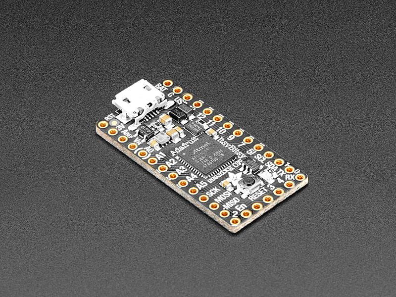
What’s smaller than a Feather but larger than a Trinket? It’s an Adafruit ItsyBitsy M0 Express! Small, powerful, with a rockin’ ATSAMD21 Cortex M0 processor running at 48 MHz - this microcontroller board is perfect when you want something very compact, but still with a bunch of pins.ItsyBitsy M0 ...
solemn cliff
I don't think the bootloader should impact your code. I was running UF2 Bootloader v3.13.0 SFHWRO and updated to latest, no issue with either. Here's test code that works for me:
desert barn
Haven't tried circuitpython yet, i've never used it. I've used the Arduino IDE for years, but I'll look into it and see I can run an example just as a test. I did run the update .UF2 through the mass storage upload already and I get the same result it's red and green when in bootloader as expected and then solid pink after any sketch starts to run or is powered on out of bootloader mode. I even ran the sketch to clear the SPI flash in case something there was causing this issue.
pine bramble
clock is 40 data is 41
https://github.com/adafruit/ArduinoCore-samd/blob/master/variants/itsybitsy_m0/variant.cpp#L98-L100
(matches schematic)
You may be able to add in massive delays to your program - APA102 isn't very time-sensitive, but sending too fast may be an issue.
Iv'e bit-banged them without trying hard at all to be accurate in any way at all. ;)
desert barn
I am now infinitely confused. I just updated 2 boards to v3.14.0 SFHWRO and ran your sketch Neradoc and BOTH are still solid pink. COM ports are 100% correct and sketches are uploading because I just popped it back in my breadboard and changed back to my oled sketch and it's running.
desert barn
Nope. Solid pink. Can't even use strip.clear(); or strip.show(); with no rgb value to turn it off. No matter what it's pink.
solemn cliff
your libraries are up to date ?
pine bramble
well I think they are set to pink (magenta) in firmware. So that sounds correct (the dotstar is functional).
solemn cliff
unless there is a revision with different dotstar pins, or it's not the right itsybitsy model, I'm stumped
pine bramble
a noisy PSU should affect initialization to magenta once in a while ;)
solemn cliff
it does go pink at startup - and is not reset if the code doesn't use it
north stream
You could try bitbanging the signals, I suppose.
desert barn
Yep, only used neopixels until now so dotstar was installed last night. Everything else is up to date. I thought about different pins too and tried every single pin on it. No luck. Doesn't matter how it's powered for me either. Both boards over usb and battery are always pink.
pine bramble
My standard DotStar call-up sequence I run on anything that has a DotStar. Always works. ;)
This is one of them; I may've simplified it elsewhere:
https://github.com/wa1tnr/ainsuForth-gen-exp-m4/blob/main/src/periph/dotstar.cpp
livid osprey
Just making sure, the board says "M0 Express" and not "M4 Express"?
Because the M4 is the same shape, but the DotStar pins are different.
solemn cliff
and while we're at it, it's not a feather, right ? you mentioned battery 😉
pine bramble
#include <Adafruit_DotStar.h>
#define NUMPIXELS   1
#define CLOCKPIN   40
#define DATAPIN    41
Adafruit_DotStar strip = Adafruit_DotStar(
  NUMPIXELS, DATAPIN, CLOCKPIN, DOTSTAR_BRG);
void setup_dotstar(void) {
  strip.begin(); // Initialize pins for output
  strip.show();  // Turn all LEDs off ASAP
}
void setup() {
    delay(900);
    setup_dotstar();
}
That should turn it off.
If that works, it's quite likely comms are correct (pins selected are correct, &c.)
desert barn
 And that's enough programing for me today! Nis I just cut down the code you linked to and uploaded it and it worked. But... only in hexidecimal not with rgb values and I needed to switch the color order to BGR. I then uploaded my code which is functionally the same to the same board AND IT WORKS WITH RGB VALUES. Then I opened a new M0 (yes they aren't M4s) and uploaded my code without Nis's first and it worked first time with RGB values. WHAT IS HAPPENING?!?!
pine bramble
bingo
pimoroni blinkt on Metro M0 Express (pins reconfigured for ItsyBitsy M0 Express):
https://termbin.com/v675
 edgy wind
Hi I am switching a relay directly with arduino and I have a problem where the period of switching intermittently becomes much shorter
It works on breadboard but not stripboard
north stream
It could be electrical interference: relay coils are an inductive load, so when they are switched off, they produce a voltage spike.
@edgy wind Does your relay get its power from the same supply that's powering your logic? Does it have a protection diode?
 willow compass
I have an Adafruit Ultimate GPS with an Arduino Mega (as well as many other pieces of hardware for a Rover), and I am having a strange issue with some functionality. We are using the GPS to find the current coordinates of the rover. I created this function from a modified version of the hardware parsing code. If I call this function from the main loop() it works as expected. However, I need to be able to call this function at a specific point in a different function to find the current position. So I need it working without the timer. However, If I remove the if statement for the timer (basically get rid of it). The function just doesn't work. In that it suddenly acts like it doesn't have a fix.
void gps(){
  char c = GPS.read();


  // if a sentence is received, we can check the checksum, parse it...
  if (GPS.newNMEAreceived()) {
    if (!GPS.parse(GPS.lastNMEA())) // this also sets the newNMEAreceived() flag to false
      return; // we can fail to parse a sentence in which case we should just wait for another
  }


  if (millis() - timer > 100) {
    timer = millis(); // reset the timer
    Serial.print("Fix: "); Serial.print((int)GPS.fix);
    Serial.print(" quality: "); Serial.println((int)GPS.fixquality);
    Serial.print(" flag: "); Serial.print(i);
    Serial.print("\n");

    if (GPS.fix) {
      Serial.print("Decimal Degrees: ");
      Serial.print(GPS.latitudeDegrees, 20); Serial.print(" "); Serial.print(GPS.lat);
      Serial.print(", ");
      Serial.print(GPS.longitudeDegrees, 20); Serial.print(" "); Serial.println(GPS.lon);
      Serial.print("*************************************\n\n\n");
    }
  }


}
My best idea so far is just set the timer insanely low time point, as I need the information on demand and the timer sometimes prevents that
cedar mountain
willow compass
I have an Adafruit Ultimate GPS with an Arduino Mega (as well as many other piec...
The timer shouldn't be necessary. However, the function will need to be called many times in a row before it gets a fix, since it's only receiving one character from the module at a time and needs to accumulate enough data to parse a whole message. So probably you should continue to call the parsing part from your loop, and have a separate function to get the last known position at the point in the code which needs it.
willow compass
cedar mountain
The timer shouldn't be necessary. However, the function will need to be called m...
the issue with this is, larger secondary functions exist that move the rover to certain positions. This is done in separate while loops. So the best I could do is get positional data before and after the rover has moved from one point to another
something similar to
loop(){

move_foward(2000 cm);
turn_left(90 degrees);
move_foward(2000 cm);
...
}

move_foward(distance_want_travel){

while(!distance_want_travel)
 mtr_move_foward();
 //Need to get GPS data here
 //Does not need to be called every loop, but enough
}
You'll unfortunately probably need to change the architecture for the movement commands so that they operate in smaller pieces, i.e. do something like set a target distance, and then each time through the loop(), check against that and move a small increment if needed. You don't want to have separate blocking while loops that interrupt the main program flow.
neon ginkgo
Okay, I have my code working but cannot figure out why my Oled will not display without the ESP32 having a serial connection. Here is my code: https://gist.github.com/NathanJ4620/2b322affe6096bec6b32cce870d8e719 I have commented out all calls to Serial but still am having this problem. any ideas
cedar mountain
neon ginkgo
Okay, I have my code working but cannot figure out why my Oled will not display ...
It might not be the real problem, but this looks suspicious:for (byte i = 0; i <= RELAY_COUNT; i++){ pinMode(relays[i], OUTPUT); digitalWrite(relays[i], 1); }Your iteration is reading off the end of your array, so you might be accidentally setting some random pin to output.
neon ginkgo
Is that what the "creates undefined behavior" warning is trying to tell me?
cedar mountain
Heh. In general, when your code isn't working, and the compiler is giving you a warning about something, that's probably a good thing to investigate. Not all warning are legitimate, but if you don't know why it's flagging a line, it's often a symptom of a genuine issue.
neon ginkgo
@cedar mountain Well that cleared up a compiler warning. but still not working. the thing that baffles me is if I upload the code it works perfectly even after pressing the EN button that resets the board but as soon as I Unplug and replug the USB the OLED fails to display but all other functionality works.
cedar mountain
neon ginkgo
<@!382380426628562955> Well that cleared up a compiler warning. but still not wo...
Weird. You might try adding a short delay to the beginning of setup(), just in case the display needs a few milliseconds after powerup to boot itself up... maybe the act of uploading code gave it the time in that scenario.
neon ginkgo
@cedar mountain ooh good thought
@cedar mountain I remember seeing somewhere, but it might have been a different oled library, a way to check for initialization. would display.avaliableForWrite() do that? throw it in the conditions of a while loop.
okay, with a 1000ms delay the oled failed to display until I opened the serial monitor.
pine bramble
desert barn
<:gus:342384086477701120> And that's enough programing for me today! Nis I just...
Documentation. ;)
One of the several uses of github is to capture wins, in a way that's quite difficult to misplace.
When you get stuck, you have to bring in management skills that are in place, basically, to manage human factors. ;)
There was an old ham radio cartoon (like a political cartoon) of the electric light bulb head guy, who'd torn the radio apart looking for the fault - only to discover he'd forgotten to plug the radio in.
When you build a radio from scratch, there are many (many) steps to take; and no guarantee when you turn it on for that first time, it'll do anything at all. ;)
But once you've built it and seen it working -- even for a moment -- never again is it the same for you. Because you saw it work, once, your own self.
The ability to just notice that moment - that it did, indeed, work, once -- if just for a moment - is important to progress that lasts. ;)
So, always stop to document the win - and take a victory lap after a big win. ;)
 vivid rock
Does anyone know how to show flash on RP2040 board as a storage device in arduino IDE (using earl philhower core and Adafruit_TinyUSB)?
I tried using msc_external_flash.ino example (https://github.com/adafruit/Adafruit_TinyUSB_Arduino/blob/master/examples/MassStorage/msc_external_flash/msc_external_flash.ino) but it fails with a bunch of errors.
As far as I can see part of the problem is that both earlphilhower core and SdFat_AdafruitFork library contain SdFat.h and SdFatConfig.h, and it is the wrong one that gets included.
 prime pawn
I have a Lora M0 board setup for aAduino and a M0 express board setup for circuitpython. I would like both of those boards to communicate back and forth via UART while allowing both of the boards to output debug info via USB.Do I have to change the way the Arduino board handles Serial in/out so I can still allow for USB debug data?
cedar mountain
prime pawn
I have a Lora M0 board setup for aAduino and a M0 express board setup for circui...
I believe you'd want to use Serial1 in Arduino to communicate to the other board on the RX/TX pins, leaving Serial for the normal debug info.
prime pawn
@cedar mountain I will give that a try
crystal frigate
Hey all. Bit of a newbie question here. I’m attempting to hook up a couple of mech switches to the AW9532 expansion board but a lot of the documentation doesn’t show it being hooked up via STEMMA


The black and white wires are hooked up to the two terminals on the switch. I’m just curious if the expander board offers the voltage I need or if I have to pull it externally.
I know I have to add a resistor… somewhere. For my button pull-ups
leaden walrus
the stemma is for connection back to the controller, it's for the I2C connection
crystal frigate
oh okay, so I have to pull my voltage from elsewhere?
leaden walrus
you're wondering about where the button's pull ups could potentially be connected?
crystal frigate
Yes
leaden walrus
you can use the VIN pin and/or rail
crystal frigate
Oh okay, great.
crystal frigate
thats it?
just GND > resistor > pin on switch and then into an input on the expander
?
leaden walrus
pretty much. the red wire from button is not used?
crystal frigate
no it's not
leaden walrus
and the button is a basic normally open type? on black/white wires?
leaden walrus
crystal frigate

Yeah I looked at that but im a bit confused because it's pulling voltage to the button
my switches only have 2 pins.
leaden walrus
 crystal frigate
Yep
leaden walrus

red is like your 1, green is your 2
the two pins in each rectangle are connected internally in the square button
that example is pulling UP
crystal frigate
Right

So it would be something like this yeah?
A1 being the input pin on the expander
leaden walrus
yep
crystal frigate
I gotcha okay
leaden walrus
test one to be sure though, before committing to all switches 🙂
crystal frigate
Yeah you bet.
and can I daisy chain the voltage and ground or no?
(wire it in series is what i mean)
leaden walrus
yes. but each button needs its own resistor.
crystal frigate
Sounds good. Thanks for all your help! this is why I dont engineer lmao. I'm an artist
leaden walrus
 crystal frigate
VIN
leaden walrus
the breadboard power rails are like that
crystal frigate
Oh sweet
Yeah I wired by stupid perf board incorrectly lmao
and I dont wanna take off the expander again
elder hare
what am i doing wrong here?
int PaletteNew[];

// from websocket.h
if ( inData.containsKey("paletteNew") )
{
  settings[selectedstrip].PaletteNew[] = { inData["paletteNew"] };
}
error
src\websocket.h:160:46: error: expected primary-expression before ']' token
I'm not sure what you're trying to do with .PaletteNew[] and I suspect the compiler doesn't either.
prime pawn
One feather is using circuitpython and the second feather is using arduino. The feather running circuitpython is sending "Hello World!" to the other feather running arduino; however, the arduino feather isn't responding back with the data that it should be receiving. I validated that circuitpython is indeed sending "Hello World!" by using a FTDI Serial TTL-232 USB Cable.
I checked the pin connections and they should be hooked up correctly. CP RX --> AR TX ... AR TX --> CP RX
I'm not sure what I should be doing differently. Am I not connecting the feathers together correctly or is it a code issue?
String inputString = "";         // a String to hold incoming data
bool stringComplete = false;  // whether the string is complete

void setup() {
  // initialize serial:
  Serial1.begin(9600);

  Serial.begin(115200);
  while (!Serial) {
    delay(1);
  }

  // reserve 200 bytes for the inputString:
  inputString.reserve(200);
}

void loop() {
  // print the string when a newline arrives:
  if (stringComplete) {
    Serial.println(inputString);
    // clear the string:
    inputString = "";
    stringComplete = false;
  }
}

/*
  SerialEvent occurs whenever a new data comes in the hardware serial RX. This
  routine is run between each time loop() runs, so using delay inside loop can
  delay response. Multiple bytes of data may be available.
*/
void serialEvent1() {
  while (Serial1.available()) {
    // get the new byte:
    char inChar = (char)Serial1.read();
    // add it to the inputString:
    inputString += inChar;
    // if the incoming character is a newline, set a flag so the main loop can
    // do something about it:
    if (inChar == '\n') {
      stringComplete = true;
    }
  }
}
I changed my arduino code to a basic serial example and it works. I think there is an issue with my serialEvent1() not fireing
firing*
cedar mountain
prime pawn
I changed my arduino code to a basic serial example and it works. I think there...
There's a note in the documentation that it doesn't work on SAMD-based boards. Is that what you have? https://www.arduino.cc/reference/en/language/functions/communication/serial/serialevent/
The Arduino programming language Reference, organized into Functions, Variable and Constant, and Structure keywords.
prime pawn
@cedar mountain I'm using the feather m0 lora board
cedar mountain
prime pawn
<@!382380426628562955> I'm using the feather m0 lora board
Yep, that's using a ATSAMD21G18 microcontroller, so the serial-event API may not work on it, I'm afraid.
prime pawn
That's ok. I can figure out another way to do this 🙂
neon ginkgo
@cedar mountain dude i found my issue! because I am using the oled feather wing with a doit esp32 board I did not have a signal to the reset on the oled. ran a wire between the EN pin on the doit esp32 to the rst pin on the wing and it works every time!!
cedar mountain
neon ginkgo
<@!382380426628562955> dude i found my issue! because I am using the oled feathe...
Excellent, nice troubleshooting!
neon ginkgo
it does seem to make the esp32 loop a few times at boot every once and a while but that I assuming because the display didn't initialize or something
north stream
prime pawn
That's ok. I can figure out another way to do this 🙂
You can just check Serial1.available() in your main loop
crystal frigate
    if button1_pin.value:
        audio.play(functionSounds[1])
        print("Button 1 pressed")
    while audio.playing:
        pass
So I wired up my button to my GPIO expander and plunked in this code. No errors, but Im not getting anything back.
button1_pin = aw.get_pin(1)  # Button on AW io 1
button1_pin.direction = digitalio.Direction.INPUT
here's how I'm initializing the input


And here’s my shoddy wiring job.
I have a weird feeling i'm pulling the resistor in the wrong place.
anyone have any ideas?
cedar mountain
crystal frigate
anyone have any ideas?
Honestly I can't tell how you have stuff wired up from the photos. Maybe you should describe how you intended the resistor to be placed?
crystal frigate
leaden walrus
supposed to be like this
cedar mountain
So that will read 0 when then button is pressed, and 1 normally.
crystal frigate
I'm using a mechanical keyswitch wired to a plug, that has 2 inputs
cedar mountain
Your code seems to be written to assume the opposite.
crystal frigate
can i reverse it in the code?
Also, it doesnt even give me the print. which makes me think it's a soldering issue
cedar mountain
crystal frigate
can i reverse it in the code?
Sure:if not button1_pin.value:
But as you say, if you're not getting anything right now, something else is wrong. It should have started to play immediately.
crystal frigate
Exactly. my speaker isnt yet hooked up but I should be getting some kind of feedback
in the form of the print
cedar mountain
If you have a multimeter, measuring the voltage at the pin while you push and release the button might eliminate some potential soldering problems.
crystal frigate
However

this is my current wiring, that appears to be different from the drawing i sent before.
heres where I think I might have the resistor in the wrong place.
cedar mountain
Yeah, that won't work... pin 1 will always read as high, regardless of the button.
cedar mountain
Ummm... you didn't follow the original diagram?
crystal frigate
No man it appears i have made a mistake haha
neon ginkgo
@crystal frigate your power needs to go through the switch. the switch is the same as touching two wires together.
crystal frigate
then where does the ground go
Sorry all. im very new to this and have only been using preassembled buttons from adafruit
neon ginkgo
the switch is not powered, it only interrupts the current path therefore it does not get a traditional ground.
crystal frigate
oh okay.
neon ginkgo
think of it as running a wire from V+ to your Digital In and then cutting it. the switch then "repairs" the cut wire when it is pressed.
crystal frigate
Okay that makes enough sense. I wish i knew this before
and then the resistor runs right before the switch, right? so the new "resisted" current goes into the GPIO
cedar mountain
Nathan, I think you might be confusing him. He was originally following a diagram which had a pullup resistor and the switch connected to ground. You're describing a different scenario with the switch to VCC and a pulldown resistor, I think.
crystal frigate

I've been following this to the best of my ability. though i cant seem to translate the button on the diagram to the switch im using.
cedar mountain
crystal frigate
I've been following this to the best of my ability. though i cant seem to transl...
The original diagram you linked to was correctly matching this description.
crystal frigate
Okay tell you what. Im gonna desolder the setup and try it again
I think my pin1 wire is in the wrong spot.
cedar mountain
Yes, changing the pin1 wire to connect on the other side of the resistor would be the minimal change.
crystal frigate
Gotcha.
it's been a cautionary tale. i shouldve REALLY tested this on a breadboard first.
neon ginkgo
also, what kind of iron are you using? does it have adjustable temperature?
neon ginkgo
are you "tinning" the tip of your iron before making a joint?
neon ginkgo
I don't know about if you're too hot but it does look like you need to apply your heat better across the pad on the perf board and the pin.
crystal frigate
Okay. Maybe keeping the iron flatter on the board?
neon ginkgo
set your iron on the pad you're going to solder in then press it into the pin then add solder to the joint, you'll probably get better results.
crystal frigate
Will keep that in mind. Thanks!
cedar mountain
neon ginkgo
UEYTRE4IRTER34 TIJGHHY
(Cat-like typing detected...)
neon ginkgo
@cedar mountain ah that'd be 4yr old daughter typing
crystal frigate
Classic 😂
pine bramble
I have a stupid question, I have an rgb strip, with 4 pinouts: 12v, R, G and B
the 12v, no problem I need to connect it to a 12v supply
But the pins named as R, G and B to what and why? Any pin is alright, do I need to use pwm, or what?
livid osprey
pine bramble
I have a stupid question, I have an rgb strip, with 4 pinouts: 12v, R, G and B
t...
12v is your common positive input, and the other three pins are the negative terminals for each color channel. Switch them to ground to turn the light on, or 12v to turn them off. Pwm is essentially your controller switching really fast to create a dimming effect based on the duty cycle, and is only needed if you need fine control of brightness/color.
No such thing as stupid questions in a help channel. 👍
As for connections, a transistor circuit is probably needed if you plan to use pwm control on an arduino, as the gpio pins are not capable of driving 12v to turn the lights off. If you just want on/off functionality, though, a switch or relay that connects rgb to ground should be enough to get the lights to turn on, as these strips usually already have current resistors included.
pine bramble
livid osprey
12v is your common positive input, and the other three pins are the negative ter...
So if I didn't want to control the brightness/colour, I can connect the rgb pins to the ground or to any pin?
Also can I connect the rgb pins to a single cable and then to a single pin? I only need them to be white so...
My board under the IIC (8 table) has a 12v pin, can't I use it to power up the led strip?
https://www.google.com/search?q=trigorilla+2560+pinout&client=ms-android-xiaomi-rvo3&prmd=ivsn&sxsrf=APq-WBsi80ZAXdelRGxfhT16qZrc8ODEDQ:1646574913170&source=lnms&tbm=isch&sa=X&ved=2ahUKEwiHpq7G0bH2AhWxSfEDHcd0C3AQ_AUoAXoECAIQAQ&biw=393&bih=768&dpr=2.75#imgrc=Wc1_u5k61O5qoM
livid osprey
pine bramble
So if I didn't want to control the brightness/colour, I can connect the rgb pins...
You can’t connect it to any pin, it has to be one capable of 12v or open circuit. You can certainly draw 12v from the 12v pin, but you should find a 12v-safe gpio to handle the other side. I know a lot of 3d printers like to borrow a spare fan/heater connection for this, as this is usually the pwm-capable higher voltage output. Whether or not your board outputs for specifically 12v fans/heaters is something you should look into before going ahead with this.
 gilded gazelle
can I get a pointer to translating Xiao sketches to QTPy ones? I am playing with the https://wiki.seeedstudio.com/Seeeduino-XIAO-Expansion-Board/
I realize it should not be hard but I need help getting started.
Seeed Product Document
basically is there a good place to learn what needs to be done in converting ANY sketch for non-ada device to ada ones
I always feel like I am starting over each time with no carryover
 ionic bridge
I'm looking at the Arduino Nano 33 BLE. It says it's based on the NINA-B306 which claims to have NFC support and "internal PCB antenna", but I can't figure out if it includes an internal NFC antenna or if I'd need to add an external one for it to work. Does anyone know this? The documentation isn't clear :p
north stream
ionic bridge
I'm looking at the Arduino Nano 33 BLE. It says it's based on the NINA-B306 whic...
Seems clear enough: the product page states: "NFC: There is the possibility of attaching an external NFC antenna between pins D7 and D8 to activate Bluetooth® pairing of the board over NFC."
ionic bridge
does that imply "it's not possible to use NFC without an external antenna" or "you can also connect an external one if you feel like it, but there's a built-in one too"
north stream
I'd guess the former: you'd need an antenna to use NFC. There isn't really room on that board for a built-in NFC antenna.
ionic bridge
Fair enough
do you know of any arduino boards with a built-in one, or with a connection port?
(or really just any boards at all, not necessarily just arduino)
north stream
Do you mean something like an add-on board or shield, or a CPU board that has onboard NFC support, or what? Usually I use add-on boards for things like that.
ionic bridge
Ideally something onboard. I'm attempting to put together a project that doesn't require obscure parts or complex soldering
But a relatively easily available addon board would be fine. I specifically need it to function as an NFC tag rather than reader/writer so PN532-based stuff won't work for me
north stream
You can use a board like this, which can connect with Stemma (so you don't need to solder) and acts as a tag for popular phones https://www.adafruit.com/product/4701
This RFID tag is really unique: it works with mobile phones just like other RFID tags, but you can reprogram it over I2C. The tag shows up as an ISO/IEC 15693 (13.56MHz) chip which is ...
ionic bridge
what is stemma?
north stream
It's a standardized connector system for I2C peripherals, designed so you can easily plug things in without soldering.
There's a nice description of STEMMA here: https://www.adafruit.com/category/1005
Adafruit Industries, Unique & fun DIY electronics and kits : STEMMA - Tools Gift Certificates Arduino Cables Sensors LEDs Books Breakout Boards Power EL Wire/Tape/Panel Components & Parts LCDs & Displays Wearables Prototyping Raspberry Pi Wireless Young Engineers 3D printing NeoPixels Kits & Projects Robotics & CNC Accessories Cosplay/Costuming ...
livid osprey
gilded gazelle
can I get a pointer to translating Xiao sketches to QTPy ones? I am playing with...
If the peripherals are analogous, it's usually just a matter of updating your pin definitions in code and board definition in Arduino IDE settings. If the chip is the same (eg. Xiao RP2040 to QtPy RP2040) you should have a pretty easy time. For switching core chipsets, you may have to manually debug some incompatibilities. I don't see any good references anywhere, but it shouldn't be too much more than changing your settings and some numbers most of the time.
gilded gazelle
I have been trying to get any sketch to run, none involving SED do anything
seeduino exp board
using qtpy2040
ionic bridge
north stream
It's a standardized connector system for I2C peripherals, designed so you can ea...
oh, that's good to know! Would the boards have a connector for the other end?
gilded gazelle
hello world(u8g2) does not display anything , I uncommented the line used on their site
north stream
ionic bridge
oh, that's good to know! Would the boards have a connector for the other end?
If you click on the "controllers" tab on that page, it will link to this category of all the controllers with that connector available: https://www.adafruit.com/category/621
Adafruit Industries, Unique & fun DIY electronics and kits : Controllers - Tools Gift Certificates Arduino Cables Sensors LEDs Books Breakout Boards Power EL Wire/Tape/Panel Components & Parts LCDs & Displays Wearables Prototyping Raspberry Pi Wireless Young Engineers 3D printing NeoPixels Kits & Projects Robotics & CNC Accessories Cosplay/Costu...
livid osprey
So there are some pinout differences between the two boards, so some modification may be necessary. Could you provide a link to the example you're trying to use?

 gilded gazelle
ok lemme make it
Pastebin
Pastebin.com is the number one paste tool since 2002. Pastebin is a website where you can store text online for a set period of time.
I get confused trying to match up the different naming schemes
livid osprey
What errors do you get in compilation?
gilded gazelle
on the pinout
none
no errors
occasionally I will see "done" in serial monitor
livid osprey
Try replacing U8X8_SSD1306_128X64_NONAME_SW_I2C u8x8(/* clock=*/ SCL, /* data=*/ SDA, /* reset=*/ U8X8_PIN_NONE);
with U8X8_SSD1306_128X64_NONAME_SW_I2C u8x8(/* clock=*/ GP25, /* data=*/ GP24, /* reset=*/ U8X8_PIN_NONE);
livid osprey
Try just 25 and 24
gilded gazelle
ok
gilded gazelle
24 and 25 ...no errors or output
trying 1 and 1
*1
SDA1 & SCL1 not defined
I am glad that the "simple swap" is not simple , I feel better 😉
my cats need tending, I will be back
livid osprey
Just to double check, you have header pins soldered to the qtpy and the pins are all properly seated?
 scarlet talon
Hello! Has anyone used the FastLED library with the arduino uno & the LPD8806 chipset ? I have everything almost working , expect the LED strip isn’t lighting with the expected colors. Any tips would be appreciated, thank you!
north stream
scarlet talon
Hello! Has anyone used the FastLED library with the arduino uno & the LPD8806 ch...
I haven't, but are you using the LPD8806 Controller in FastLED?
scarlet talon
As far as I am aware yeah, Im defining the strip as LPD8806 then passing in with addLeds() similarly to the documentation via github, with the code I'll paste in a moment , though it doesnt seem to cooperate with the coloring yet only
here it the sketch, and i have the light powered with a relay and external power source I can send a photo of if that helps ? I used this link to wire the relay to the strip, and it seems to power on/off okay https://www.circuitbasics.com/setting-up-a-5v-relay-on-the-arduino/
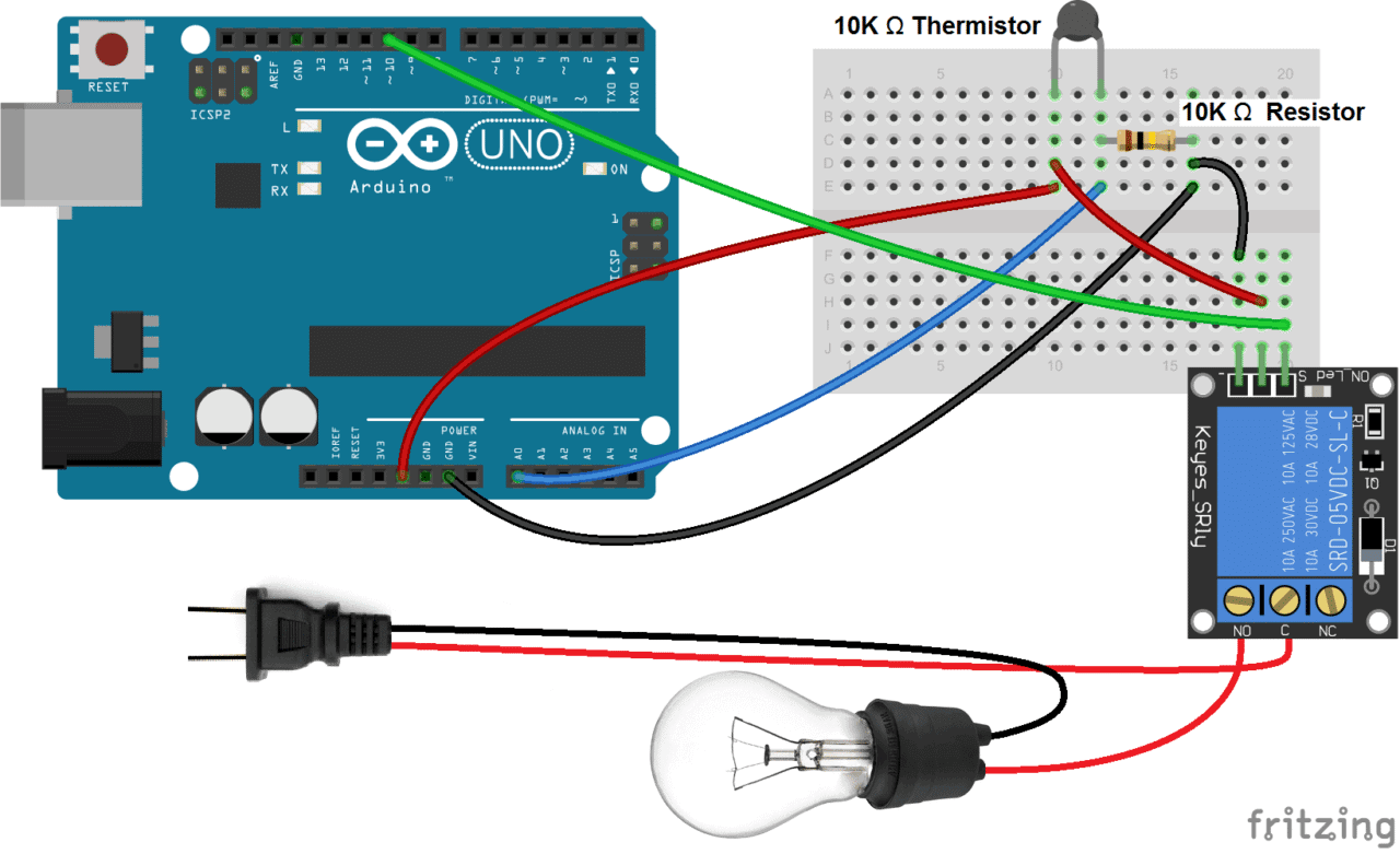
Learn how to set up a 5V relay on the Arduino use sensors to control 120-240V appliances.
here is the strip being turned on and off with the button , though the color is just regular, expect maybe the first 2 lights are pink , would you or anyone else have any idea of what that may be ? Thank you for the help as well !
north stream
When you say you wire the relay to the strip, what do you mean?
vivid rock
vivid rock
Does anyone know how to show flash on RP2040 board as a storage device in arduin...
bumping it... does anyone know the answer?
north stream
vivid rock
bumping it... does anyone know the answer?
I don't understand the question. When you say"in Arduino IDE", do you mean to the Arduino code running on the device, or having the code on the device present the flash as a mass storage device via USB, or what?
crystal frigate
So, I’m still not getting any input read from my button pin on my GPIO expander.
All the polarities check out.
crystal frigate
Lmao didnt have my resistor soldered in all good
 eternal river
any one know a usb-midi library that works with rp2040?
scarlet talon
north stream
When you say you wire the relay to the strip, what do you mean?
Sorry , I mean the led strip is externally powered , and I have that power running through a relay to turn the power on and off via button click
vivid rock
north stream
I don't understand the question. When you say"in Arduino IDE", do you mean to t...
I want to run an arduino sketch on the board so that when the board is connected to the computer it is seen as a mass storage device.
TinyUSB provides this functionality (see examples here: https://github.com/adafruit/Adafruit_TinyUSB_Arduino/tree/master/examples/MassStorage) but these examples fail to work on RP2040 boards.
 heavy onyx
so I got a pro trinket 5v and I put some code onto it, then realized some code was wrong, fixed it, and reuploaded it, will the original code mess with it, if so how would I fix that?
 native dagger
I don't know arduino super well, but I believe the original code was obliterated by your changes + reupload
heavy onyx
oh ok, awesome
 uncut aurora
Where did y’all learn how to code. I can’t find any good online classes or anything. I can’t learn on my own by just looking at other peoples code.
native dagger
I had some classes in college to get me started but they were assembly and python. Other than that I just learned by picking a project that seemed within my grasp and getting help from places like this.
Arduino is C++ so not the exact same, but you might be assisted by The C Programming Language
 rough vessel
uncut aurora
Where did y’all learn how to code. I can’t find any good online classes or anyth...
rough vessel
uncut aurora
Where did y’all learn how to code. I can’t find any good online classes or anyth...
It's been a lifelong process. I started on the family's TI-99/4A using the BASIC manual it came with to make simple games. I moved on to learn C/C++ a few years later from hand-me-down textbooks, and eventually Python and lots of other languages using online resources as something piqued my interest or was demanded by the needs of the project motivating me.
I'm lucky that I'm pretty good at following tutorials and picking up concepts as I go, but not everyone can do that.
If you're just getting started and there's something specific you want to accomplish, I'd recommend finding some tutorials or guides on similar projects and work your way up to your goal(s). There's always the path of taking formal classes, if that works better for you. There are plenty around these days, but you'll need to be more specific probably to get some good recommendations on what you're looking for.
Don't be afraid to start small and get a good foundation on the basics; it will serve you well no matter which direction you end up going.
rough vessel
uncut aurora
Where did y’all learn how to code. I can’t find any good online classes or anyth...
#books-and-tutorials might be a good channel to make inquiry in (at least I think so, I'm new here).
uncut aurora
rough vessel
It's been a lifelong process. I started on the family's TI-99/4A using the BASI...
Thank you so much! This really helps
elder hare
hmmm using FastLED i got a jsonarray with ints (palette data) that i want to set to my CRGBPalette256 PaletteCurrent;
socket.h
        if ( inData.containsKey("paletteNew") )
        {
          int arraySize =  inData["paletteNew"].size();
          settings[selectedstrip].PaletteNew[arraySize];

          for (int i = 0; i < arraySize; i++)
          {
            settings[selectedstrip].PaletteNew[i] = { inData["paletteNew"][i] };
          }
        }
main.cpp in loop
void Settings::ChangePalette()
{
    PaletteCurrent = PaletteNew;
}
settings.h
class Settings
{
public:
    uint8_t        StripNumLed;
    uint8_t        PatternBrightness;
    E_Patterns     PatternActive;
    E_Direction    PatternDirection;
    uint8_t        PatternDelay;
    E_Tail         PatternTail;
    uint8_t        PatternFadeAmount;
    E_WrapAround   PatternWrapAround;
    uint8_t        PatternBarLength;
    E_ColorUse     PatternColorUse;
    E_Animation    PatternAnimation;
    float          PatternPosition;
    unsigned long  PatternUpdate;

    CRGBPalette256 PaletteCurrent;  // <--------------------
    uint8_t        PaletteNew[];    // <--------------------

    Settings()
    {
        PatternBrightness = 64;
        PatternActive     = THEATHERCHASE;
        PatternDirection  = FORWARD;
        PatternDelay      = 70;
        PatternTail       = DUST;
        PatternFadeAmount = 128;
        PatternWrapAround = YES;
        PatternBarLength  = 4;
        PatternColorUse   = RANDOM;
        PatternAnimation  = PIXEL;
        PatternPosition   = 0.0f;
    }
    void ChangePalette();
};
but my leds are just flickering in white :S so my question is: what am i doing wrong here?
cedar mountain
It looks like you're not actually creating the new palette in memory anywhere. I'd expect to see that being malloc()ed once you know the size in the JSON parser. I'm also not sure you're using the palette correctly, since you have it defined as a uint8_t array of variable size, but it probably is a RGB array with 256 elements?
elder hare
cedar mountain
It looks like you're not actually creating the new palette in memory anywhere. I...
i looked at the CRGBPalette256 and they use uint8_t that is why i set mine to uint8_t aswell
cedar mountain
elder hare
i looked at the `CRGBPalette256` and they use `uint8_t` that is why i set mine t...
You probably want to take another look at that. It looks like it a 256-element array of CRGB structs, each of which is 3 uint8_t.
But really you ought to be using the actual class, if you're going to be using it for your palette.
elder hare
but can i copy the jsonarray directly to CRGBPalette256 PaletteCurrent; ?
cedar mountain
I don't see why not.
elder hare
cedar mountain
I don't see why not.
src\websocket.h:165:52: error: ambiguous overload for 'operator=' (operand types are 'CRGBPalette256' and '<brace-enclosed initializer list>')
             settings[selectedstrip].PaletteCurrent = inData["paletteNew"][i];
You'd want to assign to PaletteCurrent[i] to set a particular color, I believe.
elder hare
cedar mountain
You'd want to assign to `PaletteCurrent[i]` to set a particular color, I believe...
src\websocket.h:165:55: error: ambiguous overload for 'operator=' (operand types are 'CRGB' and 'ArduinoJson6192_F1::ElementProxy<ArduinoJson6192_F1::MemberProxy<ArduinoJson6192_F1::JsonDocument&, const char*> >')
             settings[selectedstrip].PaletteCurrent[i] = inData["paletteNew"][i];
still the same
        if ( inData.containsKey("paletteNew") )
        {
          int arraySize =  inData["paletteNew"].size();
          for (int i = 0; i < arraySize; i++)
          {
            settings[selectedstrip].PaletteCurrent[i] = inData["paletteNew"][i];
          }
        }
It looks like it's pulling a string out of the JSON structure instead of giving you an integer? I'm not familiar with how the JSON accessors work, but ideally you'd want to convert that to a CRGB color value first.
elder hare
hmm im still unsure how this would work
cedar mountain
The main thing to establish is what type is inData["paletteNew"][i] giving you? You might want to try assigning that to a temporary integer variable, printing it, etc. I don't know what your JSON looks like.
elder hare
cedar mountain
The main thing to establish is what type is `inData["paletteNew"][i]` giving you...
hmmm 2 problems
From Client side (Qt)
Palette Sent : QJsonArray([0,255,0,0,32,171,85,0,64,171,171,0,96,0,255,0,128,0,171,85,160,0,0,255,192,85,0,171,224,171,0,85,255,255,0,0])
From Server side (ESP32)
02550032171850641711710960255
Comparing
// Q 0,255,0,0,32,171,85,0,64,171,171,0,96,0,255,0,128,0,171,85,160,0,0,255,192,85,0,171,224,171,0,85,255,255,0,0
// E 0,255,0,0,32,171,85,0,64,171,171,0,96,0,255
- problem im missing half of the palette as you can see under
Comparing - why is the ESP32 only 1 long "string" of numbers and no
,comma between? :S
cedar mountain
How are you printing things on ESP32?
elder hare
        if ( inData.containsKey("paletteNew") )
        {
          int arraySize =  inData["paletteNew"].size();
          settings[selectedstrip].PaletteNew[arraySize];

          for (int i = 0; i < arraySize; i++)
          {
            settings[selectedstrip].PaletteNew[i] = { inData["paletteNew"][i] };
          }

          for (int i = 0; i < arraySize; i++)
          {
            Serial.print(settings[selectedstrip].PaletteNew[i]);
          }
        }
So the print() function will just print the number, with no commas.
And you're still dealing with uninitialized memory, so no telling what that's doing.
elder hare
so im not allowed to do
uint8_t PaletteNew[];
and then
        if ( inData.containsKey("paletteNew") )
        {
          int arraySize =  inData["paletteNew"].size();
          settings[selectedstrip].PaletteNew[arraySize];
        }
Nope. The linesettings[selectedstrip].PaletteNew[arraySize];is accessing the arraySize element of the uninitialized array, not creating it. You'd need to use new or malloc() to actually create the array. Although as previously mentioned, even that would be wrong because it's a uint8_t array instead of a palette object.
elder hare
i am realy confused now :S
how it would work normaly is
DEFINE_GRADIENT_PALETTE( Sunset_Real_gp )
{
    0, 120,  0,  0,
   22, 179, 22,  0,
   51, 255,104,  0,
   85, 167, 22, 18,
  135, 100,  0, 103,
  198,  16,  0, 130,
  255,   0,  0, 160
};
this is just an array of bytes
then i would simply do
PaletteCurrent = Sunset_Real_gp;
and it works
cedar mountain
What magic is that DEFINE macro doing?
elder hare
cedar mountain
What magic is that DEFINE macro doing?

GitHub
The FastLED library for colored LED animation on Arduino. Please direct questions/requests for help to the FastLED Reddit community: http://fastled.io/r We'd like to use github "...
i have no clue 😛
cedar mountain
Heh heh. Yeah, it looks like it's treating the number as a hue and converting it to a full RGB color under the hood. If you want yours to behave that same way you'll need to duplicate that logic. Probably the library has some sort of HueToRGB utility function you can use.
elder hare
cedar mountain
Heh heh. Yeah, it looks like it's treating the number as a hue and converting it...
this SHOULD work :S
        if ( inData.containsKey("paletteNew") )
        {
          int i = 0;
          memset(settings[selectedstrip].PaletteCurrent, 0, sizeof(settings[selectedstrip].PaletteCurrent));
          for(JsonVariant v : inData["paletteNew"].as<JsonArray>())
          {
              if (i >= 512) break;
                  auto x = v.as<byte>();
                  settings[selectedstrip].xyz[i++] = x;
          }

          settings[selectedstrip].PaletteCurrent = settings[selectedstrip].xyz;
        }
but does not :S
cedar mountain
elder hare
this SHOULD work :S
```c++
if ( inData.containsKey("paletteNew") )
...
You seem to be hung up on using uint8_t instead of the real RGB palette colors. You probably will need to use something like setHue(): https://fastled.io/docs/3.1/struct_c_r_g_b.html#aed04286b07335deede64d6de109a7312
 hallow seal
uncut aurora
Where did y’all learn how to code. I can’t find any good online classes or anyth...
hallow seal
uncut aurora
Where did y’all learn how to code. I can’t find any good online classes or anyth...
For a friendly introduction, a online resource is scratch.mit.edu It's designed to help bring programming into the classroom, but I followed a twitch caster build bot.land and incorporate scratch blocks as the game scripting UI.
prime pawn
code: https://pastebin.com/ZNkjirti
Error:
29 | rf95.send(data, sizeof(data));
| ^~~~
| |
| char* [32]
Points to line 29: '''rf95.send(data, sizeof(data));'''
I'm not sure what to do from here. Do I need to convert 'data' to something else?
Pastebin
Pastebin.com is the number one paste tool since 2002. Pastebin is a website where you can store text online for a set period of time.
north stream
prime pawn
code: https://pastebin.com/ZNkjirti
Error:
29 | rf95.send(data, sizeof(dat...
I suspect you want char data instead of char * data
Further, you can probably just call rf95.send(receivedChars, ndx); but you'll need to hoist ndx out of your recvWithEndMarker() routine so it persists (which you'll have to do anyway, otherwise, ndx will be 0 for every received character)
prime pawn
north stream
I suspect you want `char` data instead of `char *` data
Change the char * to char in: char* data[sizeof(receivedChars)] = { receivedChars };
?
north stream
Maybe, but you can probably just skip that and send the receivedChars buffer directly
prime pawn
Alright, I'm not exactly sure where to start
north stream
I'm not either, as I'm a little unclear on what the code is attempting to do. It looks like it's getting data from Serial1 and sending it via RF95 or sending the same buffer if there's no new data, or what?
prime pawn
I should of explained all that. Sorry.. there is data getting sent from one feather m0 running circuitpython to Serial1 on feather m0 lora running arduino. The serial data gets stored. I'm trying to send that stored data via RF95 once it's received.
data should be 100% received when a '\r' is detected
Also, python code that sends the data over: 'uart.write(bytes(hum_val, 'utf-8'))
north stream
Ah, I think several things will need to be tweaked to get that to work. Right now, it attempts to send even if newdata is false and it'll break if it gets a partial message.
prime pawn
I was thinking the same. I'm thinking I should probably move the send code into the if statement inside of the showNewData routine.
north stream
Good idea, that would address one problem.
The other one is more subtle and trickier: suppose recvWithEndMarker() gets called when it has only received the first few bytes. It'll copy those bytes into the receivedChars array, but then Serial1.available() will become false, and it will exit the while loop and the function. Those characters will effectively be lost unless it happens to get called when the \r has already been received.
What you'll need to do is preserve ndx between calls, so it can keep appending characters to the buffer until it gets the \r, terminates the string[1] and sets newData to True.
[1] You may not need to terminate the string, since ndx tells you how many characters are in the buffer, and you can use that as the count of bytes to send via RF95
Also note that the receiving routine should check for overflow, in case it gets more characters that can fit in the buffer
The good news is that your code looks good and nearly finished. The annoying news is the last bit is gonna be a little complicated.
I'm in a similar spot with some code I'm working on, and I'm not sure what to do
prime pawn
Well, you gave me good info to start with to help refactor my code. I will give this a whirl and see where it takes me. LOL. I'm still stuck on the char * issue
north stream
That one, at least, is fairly simple: char foo[] is an array of characters, char * bar[] is an array of pointers to characters
However, I don't think there's any need to copy the array before sending it, and I'm not sure the syntax you have there will copy it anyway.
prime pawn
That makes sense. I should probably move the reveivedChars into the send and not copy it
prime pawn
Ok, one more thing. What isn't making sense to me is after refactoring to rf95.send(receivedChars, ndx); I am receiving error:
   87 |         rf95.send(receivedChars, ndx);
      |                   ^~~~~~~~~~~~~
      |                   |
      |                   char*```

I'm not sure why I'm receiving that error when I have ```char receivedChars[numChars];``` at line 7.Presumably the .send() routine expects a pointer to uint8_t instead of a pointer to char. That's easy enough to fix by casting it (they're both 8-bit quantities, so it's a reasonable thing to do):
rf95.send((uint8_t *) receivedChars, ndx);
Alternatively, you could declare your receivedChars array as uint8_t instead of char.
prime pawn
I'm probably going to choose the cast route. I have a feeling if I declare the receiveChars array as an uint8_t instead of char I'm going to run into more errors 😆
Code compiled, but to be honest, I don't 100% understand what I wrote. I definitely have some homework to do 🙂
north stream
That's how we all learn
I'm trying to debug this code that's supposed to figure out that this set of points describes a circle/polygon of a particular radius around a particular center
 prime pawn
That is totally over my head. Good luck!
north stream
It may be over mine too, so I too have some homework to do!
crystal frigate
so I have an adafruit SPI sd card. (512 mb) hooked up to my arduino, and it used to recognize it before, and now it's not. Have i formatted something wrong?
My code is fine. No errors.
I haven’t looked at my wiring ,but if it was bad, it wouldn’t detect the sd card would it?
crystal frigate
i gave it
with open("/sd/test.txt", "w") as f:
    f.write("Hello world!\r\n")
no errors, but no test.txt on the board.
north stream
You may need to close the file to write it @crystal frigate
pine bramble
what's the go-to solution for restoring ItsyBitsy 32u4 5V 16 Mhz - application runs but flash won't accept a new upload; cannot erase flash using avrdude - but can dump flash contents using it.
(prefer home brew solution but open to requiring a 'proper' tool - hardware dongle)
J-Link EDU on-hand but something said it won't do 32u4.
pine bramble
Hi all, I am trying to use the QT PY RP2040 with arduino IDE, but unfortunately I have an error when loading the sketch, the port disappears. Could you tell me how to correct this error?
crystal frigate
north stream
You may need to close the file to write it <@!260842269051977731>
Any reason why the sdcard wouldn’t show up on file system though?
it's a feather RP2040
livid osprey
crystal frigate
Any reason why the sdcard wouldn’t show up on file system though?
It used to work, you said? Does the /sd/ folder show up in your CircuitPython drive? If not, you could consider reformatting the drive, assuming you don't need the files that were supposed to be on it...
crystal frigate
How would I do that? It’s an SPI connection
 sick tiger
I have a really basic problem: i cant find the connected port.
im using archlinux and an esp8266 nodemcu-v3
theres no /dev/ttyUSB*x* or /dev/ACM*x*
dmesg output is
[13148.556015] usb 1-4: new full-speed USB device number 11 using xhci_hcd
[13148.847637] usb 1-4: New USB device found, idVendor=1a86, idProduct=7523, bcdDevice= 2.64
[13148.847642] usb 1-4: New USB device strings: Mfr=0, Product=2, SerialNumber=0
[13148.847644] usb 1-4: Product: USB Serial
nothing that hints for me which port it is using
(arduino IDE is recommending /dev/ttyS0 which does exists but when i read it, nothing appears)
north stream
sick tiger
I have a really basic problem: i cant find the connected port.
im using archlinu...
Does lsusb show anything?
 buoyant hatch
pine bramble
(prefer home brew solution but open to requiring a 'proper' tool - hardware dong...
buoyant hatch
pine bramble
(prefer home brew solution but open to requiring a 'proper' tool - hardware dong...
The 32u4 has an AVR processor, so you program it using ISP.
Either a dedicated ISP adapter or another Arduino (using "Arduino as ISP") will do for burning the bootloader.
You can download the bootloader's HEX file from the ItsyBitsy 32u4 tutorial.
sick tiger
north stream
Does `lsusb` show anything?
Bus 001 Device 005: ID 1a86:7523 QinHeng Electronics CH340 serial converter```Ah, that's progress. Does anything show up in /dev/bus/usb?
buoyant hatch
north stream
Ah, that's progress. Does anything show up in `/dev/bus/usb`?
More specifically, /dev/bus/usb/001?
buoyant hatch
Yes. What are the permissions on it?
sick tiger
642(crw, rw, r) if i remember correctly, so it would need to adjust it to 666 for use
well pyserial dislikes the port, even with full access permission
Exception has occurred: SerialException
Could not configure port: (25, 'Inappropriate ioctl for device')```642 is rw, read-only, write-only. That's a bit strange...
buoyant hatch
I don't know if you need to install the driver (https://aur.archlinux.org/packages/ch34x-dkms-git) or if that's already built into the kernel.
buoyant hatch
The c stands for the file type (character special), like d for directory.
sick tiger
ah i see, sweet it works again.
thanks for the help y'all
pine bramble
@buoyant hatch 'or another Arduino' and the program used is pretty much what I'm wondering about.
specific to 32u4 target to receive the .hex-encapsulated image (which the Arduino IDE already has ("caterina" or similar).
Even more so: is the 32u4 specifically a candidate for this type of homebrew ISP, as its target MCU (the one getting new firmware to restore a bootloader, erase flash &c.)
sick tiger
buoyant hatch
642 is rw, read-only, write-only. That's a bit strange...
but that seems usual it was mentioned somewhere in the arch wiki, and it was proposed to create a (udev?) task or something to always apply it on frequent reconnecting
buoyant hatch
pine bramble
<@!380747082576691201> 'or another Arduino' and the program used is pretty much ...
Details on ArduinoISP are in https://www.arduino.cc/en/pmwiki.php?n=Tutorial/ArduinoISP, you have to adapt the procedure for a Leonardo target to the ItsyBitsy.

Arduino ISP turns your Arduino into an in-circuit programmer to re-program AtMega chips.
Any Arduino compatible board which takes the ArduinoISP sketch should work as a programmer.
I say should because I've only ever used an Uno for that though...
north stream
sick tiger
but that seems usual it was mentioned somewhere in the arch wiki, and it was pro...
I suspect the CH340 package implements a udev rule to create the ttyUSB port you're seeing
buoyant hatch
north stream
I suspect the CH340 package implements a udev rule to create the ttyUSB port you...
Take a look in /etc/udev/rules.d.
sick tiger
not regular text files i could look into so heres the name, could be one of them
 buoyant hatch
They should all be regular text files. Try cating one of them.
According to https://wiki.archlinux.org/title/Udev, another place for these rules is /usr/lib/udev/rules.d.
sick tiger
/usr/lib/udev/rules.d is holding most of the udev rules
but problem is solved so.
pine bramble
@buoyant hatch Thanks. The reason I ask: avrfreaks.net is rather insistent (from several years ago) in multiple posts that 32u4 is more 'proprietary' and requires a special tool called AVR Dragon or .. Atmel ICE and will not work with a homebrew job.
(avrdude supports AVR Dragon explicitly)
I've been unable to erase the ItsyBitsy 32u4 5V 16 MHz board using avrdude but the same command line works fine, on CircuitPlayground Classic 32u4.
This really is a 'does anyone (reading this) have hands-on experience' question, I think.
north stream
If it works on one 32U4 and not the other 32U4, that implies it's not a 32U4 problem specifically, but something hinging on a difference between a 32U4 Itsy and a 32U4 CPC
buoyant hatch
Since the main processor also handles USB communications on 32u4 boards, that might be a little more fragile.
You can try the fixes in https://learn.adafruit.com/adafruit-feather-32u4-basic-proto/feather-help if it's just a USB or watchdog timer issue (or if whatever the 'bitsy runs is crashing).
 pine bramble
north stream
If it works on one 32U4 and not the other 32U4, that implies it's not a 32U4 pro...
pine bramble
north stream
If it works on one 32U4 and not the other 32U4, that implies it's not a 32U4 pro...
The ItsyBitsy 32u4 ran fine for many dev cycles.
I *think* I uploaded it Uno firmware (in platformio).
Hasn't worked since, to erase the flash.
Can dump firmware using avrdude, on the trouble board, no problem.
Last code uploaded (which may be for the Uno!) run fine on cold reset; happens to be an interactive Forth interpreter.
Successfully echo's the commands sent to it in SerialMonitor, including interim (verbose) print statements.
good flash dump:
https://termbin.com/eyto
The application area has a strange report to give (when a dump flash 0x0 0x1000 is requested) but the Forth code (regular Arduino IDE based code) runs anyway.
strange here:
avrdude> dump flash 0x0 0x1000
>>> dump flash 0x0 0x1000
0000  11 64 11 64 11 64 11 64  11 64 11 64 11 64 11 64  |.d.d.d.d.d.d.d.d|
0010  11 64 11 64 11 64 11 64  11 64 11 64 11 64 11 64  |.d.d.d.d.d.d.d.d|
0020  11 64 11 64 11 64 11 64  11 64 11 64 11 64 11 64  |.d.d.d.d.d.d.d.d|
(truncated by termbin!)
tail end is here:
'erase' in interactive avrdude normally fills to 0xff 0xff 0xff.. in the application space.
On this one board (one instance, not 'any' itsy32u4 but my one and only) .. it has no effect at all.
Whereas it behaves as expected on my (also one and only) Circuit Playground Classic (32u4) board.
(when CircuitPlayground Classic gets erased, the bootloader LED pulses endlessly, instead of timing out after eight seconds or so).
pine bramble
One user reports a win - Leonardo (32u4) bootloader reflash, with a:
following a tutorial here:
 safe halo
Any reason why I cant use a saved variable to start a wIfI connection
  sys_Settings.network.WiFi_STA_SSID = "Castle"
  sys_Settings.network.WiFi_STA_Password = "password"
  Serial_2.println("Connecting to WiFi: ");
  Serial_2.println(sys_Settings.network.WiFi_STA_SSID);
  Serial_2.println(sys_Settings.network.WiFi_STA_Password);
  //Works
  WiFi.begin("Castle", "password");
  //doesnt Work
  WiFi.begin(sys_Settings.network.WiFi_STA_SSID, sys_Settings.network.WiFi_STA_Password);
when I load from the variable it comes back with a bunch of Yen Symbols

Prior to starting the WIFI with the variable I can print screen them and they are correct but afterwards they are all yen symbols
pallid grail
@leaden walrus I can't figure out how to make the STEMMA QT port work on the ESP32 Feather V2. I know there's a power pin, I tried pulling it high, also tried doing the INPUT polarity OUTPUT thing that the ESP32S2 Feather does, that didn't work either. I'm trying to run the i2c_scan_test. I pulled the #if defined(ADAFRUIT_FEATHER_ESP32_V2) out of another file that Limor updated for this recently, so that should at least be right...
leaden walrus
hmm...not sure. lemme check. i think i got one.
pallid grail
Also, the I2C scan is.... running really weird. I mean, it compiles and loads, but there's no power to the STEMMA QT port. But the scan is supposed to run every 3 seconds, and it's not doing that..... more like every 10 or something longer than that sometimes.
Limor assumed it would Just Work ™️ but that is not the case without adding something to handle the power pin at least.
leaden walrus
what board are you selecting?
leaden walrus
not sure. but looks like the v2 variant has been merged, but not released.
pallid grail
We're waiting on a release or something from Espressif, so it'll be a while apparently, before there is a "ESP32 V2" to pick.
leaden walrus
pallid grail
I'd say I could add the latest URL to the board manager options, but this is what Limor said to do for now.
But that's what's making it not work?
That we're not choosing the "right" board?
I can bring this up with Limor, but I wanted to make sure it wasn't a me-problem first.
leaden walrus
the URL would be the same. they (espressif) just needs to make a new release. latest release if from before V2 board def was merged in.
pallid grail
Oh. I thought there was a "stable" and "latest" URL available.
Limor said not to wait on Espressif. Implying they take a while to release.
I guess I'll ask her how this is suppose to work then.
She's stepped in a lot on this guide to keep me from being blocked on things, so I figure I shouldn't spend too much time trying to figure it out myself.
leaden walrus
@pallid grail this works:
// --------------------------------------
// i2c_scanner
//
// Modified from https://playground.arduino.cc/Main/I2cScanner/
// --------------------------------------

#include <Wire.h>

// Set I2C bus to use: Wire, Wire1, etc.
#define WIRE Wire

void setup() {
  // turn on power
  pinMode(2, OUTPUT);
  digitalWrite(2, HIGH);

  // set pins (SDA, SCL)
  WIRE.setPins(22, 20);

  // make rocket go
  WIRE.begin();

  Serial.begin(9600);
  while (!Serial)
     delay(10);
  Serial.println("\nI2C Scanner");
}


void loop() {
  byte error, address;
  int nDevices;

  Serial.println("Scanning...");

  nDevices = 0;
  for(address = 1; address < 127; address++ )
  {
    // The i2c_scanner uses the return value of
    // the Write.endTransmisstion to see if
    // a device did acknowledge to the address.
    WIRE.beginTransmission(address);
    error = WIRE.endTransmission();

    if (error == 0)
    {
      Serial.print("I2C device found at address 0x");
      if (address<16)
        Serial.print("0");
      Serial.print(address,HEX);
      Serial.println("  !");

      nDevices++;
    }
    else if (error==4)
    {
      Serial.print("Unknown error at address 0x");
      if (address<16)
        Serial.print("0");
      Serial.println(address,HEX);
    }
  }
  if (nDevices == 0)
    Serial.println("No I2C devices found\n");
  else
    Serial.println("done\n");

  delay(5000);           // wait 5 seconds for next scan
}
but not sure that's anything you'd want to put in a guide
since it's using specific pin numbers, and not #defs
leaden walrus
once the release is made, and the V2 board option shows up in the Arduino IDE, the sketch could then use NEOPIXEL_I2C_POWER
pallid grail
right.
leaden walrus
and probably won't need the setPins() call
pallid grail
I just said pretty much exactly that to Limor, heh.
Anyway, she's going to figure something out.
Thanks for the help, but you're off the hook now. 🙂
leaden walrus
sure. np. this is going to unfortunately be confusing probably.
can get things to work right now. but not really in the way one would in the long run.
severe latch
Hi. Is there any documentation available to find the exact stack and heap size for the nRF52840 ?
I went through several documentations for the nRF52840 on learn.adafruit.com but was only able to figure out that the total SRAM is 256 KB.
There is an SRAM layout presented for the nRF52832 but couldn't find one for the nRF52840
safe shell
severe latch
only the SRAM layout ** for nRF52832 is provided there I believe
stable forge
severe latch
Hi. Is there any documentation available to find the exact stack and heap size f...
looks like heap and stack are each 8192. That could certainly be increased.
severe latch
hmm okay. Interesting to note , thank you !
severe latch
Is there a way that I can verify that ? I am trying to allocate a static array >8 KB (to verify stack size) and see if an error will pop up but seems like the compiler is not showing errors anyways.
Just running this simple sketch
#include<Arduino.h>
#include <Adafruit_TinyUSB.h>

void setup()
{
  //allocate static array with 10 K size
  uint8_t buff [10240];
  memset(buff,0,sizeof(buff));
}

void loop()
{

}
 violet shell
Hi all, I am having some difficulty in running code for the Mikroe LSM6DSL with the feather M0 and not sure what to do
this is the following error I get when trying to run the example code through the Ardiuno IDE
 leaden walrus
looks like the example is expecting a different board
are you connected to the SCL/SDA pins on the Feather M0?
LSM6DSLSensor AccGyr(&Wire, LSM6DSL_ACC_GYRO_I2C_ADDRESS_LOW);
try that
and comment out the other stuff
violet shell
leaden walrus
are you connected to the SCL/SDA pins on the Feather M0?
yes i have
leaden walrus
ok. try the above.
just need to change code to accommodate using on a different board than what example was originally written for
violet shell
i have changed the code to as above bu i still get the erro but for #define INT1 PB11

the code i am using is from the example library for the board so shouldn't it work straight away, if I'm not mistaken
leaden walrus
comment out the other stuff
the #defs and dev_i2c setup
"board" = the feather m0, not the LSM6DSL
if you're following a guide that says that code will work on a Feather M0, please link to guide
violet shell
leaden walrus
if you're following a guide that says that code will work on a Feather M0, pleas...
I couldn't find one where i c
violet shell
leaden walrus
comment out the other stuff
I'm not too sure i understand do you men like this
 leaden walrus
yep
and also the line the creates dev_i2c
er. wait. no. just looks commented out.
where did you get that library?
violet shell
it is one that i downloaded within the IDE app
leaden walrus
arduino ide library manager?
violet shell
yes the LSM6DSL v2.0.0
leaden walrus
is the the LSM6DSL board you are using?
https://www.mikroe.com/lsm6dsl-click
violet shell
leaden walrus
is the the LSM6DSL board you are using?
<https://www.mikroe.com/lsm6dsl-click>
yes
I've connected the LSM6DSL board like so
 violet shell

 violet shell
leaden walrus
does that look like the library you installed?
violet shell
leaden walrus
does that look like the library you installed?
yep that's the one
leaden walrus
which example are you using?
https://github.com/stm32duino/LSM6DSL/tree/main/examples
violet shell
currently trying the tilt one
leaden walrus
example is specific to STMicrolectronics STM32 IOT Discovery Kit
which is why you need to deal with different pin definitions
for the feather
violet shell
leaden walrus
example is specific to `STMicrolectronics STM32 IOT Discovery Kit`
ohh okay that makes sense
so how would I need to change it so that it works with the Feather
leaden walrus
//#define SerialPort Serial
//#define I2C2_SCL    PB10
//#define I2C2_SDA    PB11
//#define INT1        PD11

// Components.
//TwoWire dev_i2c(I2C2_SDA, I2C2_SCL);
LSM6DSLSensor AccGyr(&Wire, LSM6DSL_ACC_GYRO_I2C_ADDRESS_LOW);
try that
// is how you comment out lines
and for the feather, can just use the Wire reference directly (first parameter)
violet shell
leaden walrus
```cpp
//#define SerialPort Serial
//#define I2C2_SCL PB10
//#define I2C2_SDA...
i have this already i think
violet shell
leaden walrus
and for the feather, can just use the `Wire` reference directly (first parameter...
what would i replace this with instead?
leaden walrus
oh. you used block comment.
that'll work too
but you need to comment out the dev_i2c line also
TwoWire dev_i2c(I2C2_SDA, I2C2_SCL);
that line
and change
LSM6DSLSensor AccGyr(&dev_i2c, LSM6DSL_ACC_GYRO_I2C_ADDRESS_LOW);
to
LSM6DSLSensor AccGyr(&Wire, LSM6DSL_ACC_GYRO_I2C_ADDRESS_LOW);
 leaden walrus
delete that line, with /*
violet shell
ok that runs the code further down to a point where now the SerialPort is not declared in the scope
 leaden walrus
ugh...yah. there's more that needs changing....other refs to dev_i2c...
and INT1 is needed
how did you end up using the STM library? just by searching in Library Manager?
violet shell
leaden walrus
how did you end up using the STM library? just by searching in Library Manager?
yes that is hat i did
int 1 is defined further up but has been commented out
leaden walrus
you'll need to wire the int pin to use that example
it's using one of the feature detections of the LSM and using the INT pin to report it back to the main board (feather in your case)
 violet shell
ahh ok so where would i connect that pin to onto the featherboard?
leaden walrus
which feather m0 do you have?
nvm. it's in the photo 🙂
All pins can be interrupt inputs
so you have plenty of options
looks like you're using 5 for something?
violet shell
leaden walrus
looks like you're using `5` for something?
yes 5 is for a piezo buzzer
leaden walrus
so 6, or any of 9, 10, 11, 12
leaving out 13 since it has an LED attached
#define SerialPort Serial
#define I2C2_SCL    SCL
#define I2C2_SDA    SDA
#define INT1        6
and then go ahead and use that #def block, but change it to that
change INT1 to whatever GPIO pin you end up using
and uncomment this as well
TwoWire dev_i2c(I2C2_SDA, I2C2_SCL);
ok wsa just about to ask about this
leaden walrus
basically put sketch back to original code