
#help-with-arduino
1 messages · Page 105 of 1
 pine bramble
basically what I want to do with this code is convert the acceleration to velocity using the equation of motion
V = Vo + at
V = Velocity
Vo = Velocity previous value
a = acceleration
t = time
btw this is for a car project I made a simple data logging pcb with a bmi088 and samd21 with a flash chip and sd card to log the acceleration and velocity data to give a rough overview of the speed the car travelled at. so that is why I've been asking question related to this software is not really my forte. just wanted to let u know for transperency
 livid osprey
Haha, that output is correct. If you add an extra Serial.println("--------"); to your loop(), you'll see what each variable is in each loop more clearly...
livid osprey
I only realized because I've made the same mistake before haha
pine bramble
😆
 lapis meteor
How am I supposed to connect this, those holes have no end? Should I be using pin header for it?
 pine bramble
That's probably a 16x2 LCD.
There's usually 14 pins for a monochrome and a few more for color iirc.
lapis meteor
Oh so will I be attaching those pins with pin header to connect it to breadboard?
And is soldering necessary?
livid osprey
lapis meteor
How am I supposed to connect this, those holes have no end? Should I be using pi...
Soldering is necessary to connect any header to the holes.
If you're using a breadboard, a pin header would be ideal.
lapis meteor
What if I do without soldering
lapis meteor
Hmmmm
pine bramble
The bottom tier (the perfboard) spacing is narrower to affect a wedge.
Just by one row. ;)
 livid osprey
I've taken thin wires and kinda looped them through and twisted them to secure in place. It does require you use some sort of insulation to prevent shorts, though, so doing that many pins is kind of a hassle
lapis meteor
So it means I can use lcd on breadboard without soldering?
pine bramble
I've pressed an RPi Pico RP2040 onto a breadboard directly using the same idea.
My guess is it would slip more since you can't fold any pins over like you can using perfboard.
lapis meteor
Slip?
pine bramble
Yeah the wedge wants to back out essentially.
lapis meteor
Oh
pine bramble
Once it's pressed in I fold at least one pin over on each side to prevent backslipping.
lapis meteor
k I will try
pine bramble
;)
The entire idea is dependent on the header pins making a press-fit contact with plated thru-holes of a PCB
lapis meteor
Is there a way other than header pins
pine bramble
There's not a lot of pressure available to ensure good contact with most methods people have tried.
lapis meteor
Oh
pine bramble
You can buy a pre-soldered module from vendors, sometimes.
lapis meteor
I see
 median mica
Has anyone used a trinket M0 as a keyboard and mouse using Arduino? I’m trying to make a two button device where one button acts a SPACE and the other button acts as a LEFT MOUSE CLICK.
I know I can do this in Circuitpython but I run out of space on the bare bones trinket M0 running CP.
 cold silo
I have not, but I suspect it would work well.
I have a question regarding the RP2040 (feather). Incidentally I am also building an HID (keyboard) but that's not too relevant. I tried with python because setup was so easy but Python feels weird to me and I really wanted to use C(++), and I'm wondering what people's thoughts are on using the unofficial Arduino support because I can't for the life of me get it to run C based on the official documentation, particularly on a Windows machine. Alternatively, has anyone gotten a good flow for using it with C sans Arduino like in the official docs except on a Windows machine?
median mica
Thanks @pine bramble I knew I read a guide on it somewhere.
 pallid grail
cold silo
I have a question regarding the RP2040 (feather). Incidentally I am also buildin...
pallid grail
cold silo
I have a question regarding the RP2040 (feather). Incidentally I am also buildin...
Answered in #help-with-linux-sbcs. 🙂
pine bramble
how do I tell if my arduino uno rev1 I think or mega 2560 is more suitable for a project?
so that I only use the minimum needed microcontroller so I don't overpay for my use
pallid grail
@leaden walrus I'm back for more. This time it's something other than pins though. Sort of. I'm updating the pins for a few boards in the Philhower core. Three boards that have NeoPixels do not have the NeoPixel pins defined. How do I test whether I did it right? I mean, I can compare it to the PrettyPins, which is where I got the info, but I would like to know it's accurate. I'm not sure how to test Arduino changes like that. I have a fork, and I have the updated code locally.
pallid grail
Right? It's not as easy as dumping it into a folder and uploading a sketch.
Ok, at least I'm not missing something obvious.
I'll double check my work against the diagrams, and call it good.
 leaden walrus
correct. since the BSP install does "stuff"
pallid grail
Right.
And doesn't pull directly from GitHub either. So I can't add my own fork to the IDE.
AFAICT.
Ooh. Can I push my work, and have you check it too?
leaden walrus
it's only going to be a few header files, right?
leaden walrus
this is a bit of hack, but easy since it's only a few files...
you're going to fork/clone the core repo, make changes there, etc. as normal
pallid grail
Done
leaden walrus
to test - manually replace the BSP files with ones from fork
pallid grail
Oh, I didn't realise they were local.
I thought it was always pulling from the link in the IDE prefs.
Ok, that makes sense.
leaden walrus
you're on mac?
pallid grail
Yeah just found it.
pallid grail
Yep
leaden walrus
ok, yah, just drill down in there and manually replace
pallid grail
Yep in progress. Thank you!
leaden walrus
and then recompile a test sketch
pallid grail
It compiles every time I try to load it, right?
leaden walrus
yes. or can use the check mark in the ide.
pallid grail
Got it.
leaden walrus
instead of arrow
pallid grail
Right
leaden walrus
to sanity check it's using the files, intentionally add a syntax error to one and make sure you get a compile time error
pallid grail
Oh to the .h file?
pallid grail
oki
leaden walrus
just to verify some cached version isn't being used, etc.
pallid grail
failed on hello.
leaden walrus
cool. so it's using the files. can remove and test the real changes.
leaden walrus
np
at some point, would like to figure out a non-hack way for this. just haven't done more than simple patches, so hack worked for now.
pallid grail
Yeah fair enough. Same in my situation. I wouldn't even know where to begin with more than simple fixes. Which, by the way, wouldn't have been able to do this without your help understanding the (#u) from yesterday. So thanks for that. Was ezpz.
3 for 3!
livid osprey
pine bramble
how do I tell if my arduino uno rev1 I think or mega 2560 is more suitable for a...
The main difference is the number of pins/ports. The MEGA2560 has 4 UART, 16 analog IO, and like 50+ GPIO?
Start with what you need to do and see if it fits on the pins of an UNO, that'll tell you right away.
 proud lion
Hi there. I'm having an issue getting my Adafruit Metro ESP32-S2 to recognize an SD card. I'm using the Adafruit Data Logger shield and using the SD_Test example for the board but the serial monitor says "Card Mount Failed". I know it's not a problem with the SD card or shield because it works on my Adafruit metro board. Any ideas about what I need to change in the code for it to work?
 safe shell
I haven't done the audio part, but SD card is straightforward, and SPIFFS is quite do-able. You can transfer files between them, or I believe you can load up SPIFFS at flash time.
 agile rampart
Thank you. I am currently using SPIFFS to store web pages. They are easy to work with. The bluetooth connection to the headset and the playing of the audio file across that connection is my real challenge.
lapis meteor
is it a good idea to use dc motors without the driver?
pine bramble
the only thing that shouldn't be done with motors afaik is connecting power directly to it without a resistor. Most small motors are gonna blow up if you put 2A or 9A on them...
lapis meteor
2A or 9A what?
pine bramble
do you mean what as in you don't know what I mean or as in it seem incorrect?
lapis meteor
i mean what do you mean by 2A/9A
pine bramble
do you know ohm law ?
lapis meteor
power?
pine bramble
2/9 amperes
pine bramble
Most electronics scale motors can't handle 2 or 9 amperes (ie:2A/9A) . The typical batteries are 1.8V or 2V for AA and 9V for the square one
no the opposite
lapis meteor
oh
pine bramble
if you don't use a resistor it will burn and smoke in a few seconds
lapis meteor
i will be giving it power directly from arduino no external battery
pine bramble
so most of them operate in the miliamps range
pine bramble
so you have to provide a resistance like 1000 ohm
lapis meteor
got it ty
pine bramble
so the current from the battery goes from 1.8/2/9A to 1.8 /2 / 9 miliampere
lapis meteor
oo
pine bramble
the datasheet of your motor will tell you the exact range it can handle
do you know what motor you have ?
as a general rule you can't assume an arduino or other board have built-in protection for leds or batteries
they both require a protection resistor
lapis meteor
pine bramble
do you know what motor you have ?
i dont have one, but i will be getting this one https://www.amazon.in/Sparklebox-Motor-100RPM-Soldered-Arduino/dp/B09JC96SXL/ref=sr_1_18_sspa?crid=3EVJ16AXBY3LB&keywords=dc+motor&qid=1643288394&sprefix=dc+m%2Caps%2C255&sr=8-18-spons&psc=1&spLa=ZW5jcnlwdGVkUXVhbGlmaWVyPUEzUjQ5UTIzMFJUNTRTJmVuY3J5cHRlZElkPUEwODE5ODY1MjRJT0pTWkNJS0xHRSZlbmNyeXB0ZWRBZElkPUEwMTIzMzA2M043Q0RYQkFCQkROWSZ3aWRnZXROYW1lPXNwX210ZiZhY3Rpb249Y2xpY2tSZWRpcmVjdCZkb05vdExvZ0NsaWNrPXRydWU=
pine bramble
do you understand so far or I lost you somewhere ?
lapis meteor
pine bramble
as a general rule you can't assume an arduino or other board have built-in prote...
i see
lapis meteor
pine bramble
do you understand so far or I lost you somewhere ?
yes i understood:)
pine bramble
do you have an arduino or something similar ?
lapis meteor
yes i do (arduino uno), ive also made couple of cool projects
pine bramble
may I suggest you experiment with a cheap motor on your arduino before you do something on such an expensive kit ?
lapis meteor
sure
btw i also have a stepper motor with me but i realized it won't be good for fast things
pine bramble
and possibly read a tutorial like this one https://learn.adafruit.com/adafruit-arduino-lesson-13-dc-motors/arduino-code so you learn more about the different types of motors, PWM, drivers, ESC etc
 lapis meteor
alright
pine bramble
your kit also come with resistors, but I couldn't find out if a manual came with it
lapis meteor
oh
pine bramble
stepper motor and dc motors are usually for different usage
lapis meteor
ik
pine bramble
I'm oversimplifying but stepper motor usually position whereas dc motor usually rolls
lapis meteor
oo anyways ty for helping i gtg now
pine bramble
no problem
livid osprey
@lapis meteor Running small toy motors for short durations might be manageable on an arduino, but you do risk damaging the arduino if you overdraw the current. Arduino is only designed to handle 40mA output from a single digital output, so you should definitely use at least 125 ohms to limit your output current to a safe range.
Keep in mind that those motors are 40-80mA without load, meaning you can expect them to draw more current when the motors aren't freely spinning. Stall current can easily burn out an Arduino if you're not careful, so I strongly recommend using a driver chip instead of direct GPIO pins.
lapis meteor
i understood, so i should get a driver chip
 severe latch
Hello. I am using the nRF52840 feather board powered with a battery and trying to measure the voltage using the sketch provided on Adafruit.

However, the measured voltage was always between 4.1 V and 4.2 V (even after leaving the battery and the board running for a while)
am I doing anything wrong ?
I appreciate any help/suggestions
livid osprey
severe latch
However, the measured voltage was always between 4.1 V and 4.2 V (even after lea...
How big a battery are you using, and how long is "a while?"
Are you actually running it on battery or is it plugged into USB?
severe latch
livid osprey
How big a battery are you using, and how long is "a while?"
like around 50 minutes
severe latch
livid osprey
Are you actually running it on battery or is it plugged into USB?
running it on battery and reading the values through bluetooth
livid osprey
It's unlikely there's an issue with it if it's reading in the range of 3.2-4.2V, but you could use an external measurement to validate it. Multimeter, voltmeter, etc.
severe latch
Okay. Thank you
one more question, even when I disconnected the battery and left the board connect via USB ... the voltage reading remained 4.2 V
should it go to 0V when the battery is disconnected ? or not as it is still powered by the USB
 gilded swift
severe latch
one more question, even when I disconnected the battery and left the board conn...
gilded swift
severe latch
one more question, even when I disconnected the battery and left the board conn...
The lipo charger pushes 4.2V to the battery traces
It does so regardless of if a battery is present
severe latch
okay makes sense . thank you
 west tapir
Hi. I'm using a QT-Py to run a temperature monitor for my outdoor fridge/freezer. I'm programming it via arduino, not CircuitPython. I have three DS18b20 one-wire sensors in parallel, and an SSD1306 screen. It compiles fine, and upload is hit-or-miss, mostly "hit" (occasional COM Port collisions that I'm not sure of, but since it usually works, I'm not yet worried about that.)
Anyhow, I build and upload the sketch and it runs fine, updating the screen and what-not. But if I hit reset, or unplug and plug it back in, it's as if the sketch was never uploaded.
I've read about the bootloader, but it seems just to be an "alternative" way to upload the sketch.
I'm sure it's simple, but what am I doing wrong? Is there a step I'm missing, to get the sketch into NVM?
 stable forge
west tapir
Hi. I'm using a QT-Py to run a temperature monitor for my outdoor fridge/freezer...
stable forge
west tapir
Hi. I'm using a QT-Py to run a temperature monitor for my outdoor fridge/freezer...
which QT Py?
west tapir
M0 (looking for deeper detail...)
stable forge
if the sketch runs when it's uploaded, then it's in flash. Could you upload your sketch? Use the + button on the left
west tapir
Here's the doohickey. The pixel at the bottom crawls left to right as proof-of-life.

BTW - Adafruit QT PY (SAMD21)
BRB - running to grab the 3D printed case. 🙂
Back.
stable forge
// start serial port
  Serial.begin(BAUD_RATE);
  while (!Serial);
ARRRRGH.
stable forge
This will wait forever if there is no serial connection. Is that what you want?
[re threads; it's ok to make one, it's ok not]
west tapir
Nope. Lemme see. (It was there because it eliminated a runtime issue. Get it running, get it running right, get it running well.) I'm still on step 1. 🙂
stable forge
is that why you said "ARRRRGH"?
west tapir
yes... 😦
stable forge
ok 🙂 You can put a delay there if you want, a second or two, or wait up to a certain amount of time for it to be ready, etc. But you may not need that.
this is a really common issue; I thought the chances were at leat 50/50 that was the problem
stable forge
np!
lapis meteor
Can I use uln2003 driver for DC motors?
 cedar mountain
It may be difficult to measure the data line with a multimeter, since the signals are so fast. It would likely idle at 0V, but when LEDs are being updated it would be some intermediate voltage, averaging out 0V and 3.3V data bits.
 lilac rain
cedar mountain
It may be difficult to measure the data line with a multimeter, since the signal...
lilac rain
cedar mountain
It may be difficult to measure the data line with a multimeter, since the signal...
thanks! ive ruled out a bad board and bad ring as ive gotten it to somehow light up accidentally lol
 north stream
lapis meteor
Can I use uln2003 driver for DC motors?
north stream
lapis meteor
Can I use uln2003 driver for DC motors?
Yes, it's suitable for small motors.
 silent void
Hello guy, I not speak English very well, but, i need help, I'm new here, and I don't know how to record my code in adafruit , could anyone help me? I have adafruit pro trinket.
Eu sou Brasileiro, se tiver alguém pra me ajudar, eu agradeço
stable forge
silent void
Hello guy, I not speak English very well, but, i need help, I'm new here, and I ...
Write what you want to do in Portugese, and we'll try Google Translate. "record my code" -- do you mean write a program? You would use the Arduino IDE.
This place may help: https://forum.arduino.cc/c/international/portugues/51
pine bramble
Hi Everyone, I would like to use the RFID component ST25DV16K with the QT Py RP2040 microcontroller in Arduino IDE. Do any of you know how to install this board in the Arduino IDE?
lilac rain
are these the correct PIN numbers to reference in the arduino IDE. i assumed D6 was pin 6, and wasnt getting anything.
 north stream
There are two sets of pin numbers, the purple ones and the grey ones. The diagram shows "Arduino" in purple, so I'm guessing the purple numbers are for the Arduino IDE.
lilac rain
north stream
There are two sets of pin numbers, the purple ones and the grey ones. The diagr...
thanks so if i defined something in the arduino IDE for pin 6... then nothing would happen since there is no pin 6 for the arduino IDE? I assumed d6 was in pin 6 and spent last night almost pulling my hair out LOL
north stream
Probably so, but I'm not sure what (if anything) Arduino pin 6 would map to. You'd have to pull open the board definition files to see what's going on (I've done this, once in a while, when I got curious)
lilac rain
thank you @north stream, appreciate your time
 rugged plinth
Is this the Sdfat library needed to use the adafruit spi flash library - https://github.com/adafruit/Adafruit_SPIFlash

GitHub
Contribute to adafruit/Adafruit_SPIFlash development by creating an account on GitHub.
pine bramble
Thank you Cater 🙂
 cold lagoon
i need an arduino with 6 pwm pins but i also need the mosi, miso, sck pins free.
 vivid rock
how about an Rp2040 based board? e.g. https://www.adafruit.com/product/4888
A new chip means a new ItsyBitsy, and the Raspberry Pi RP2040 is no exception. When we saw this chip we thought "this chip is going to be awesome when we give it the ItsyBitsy ...
 true spear
vivid rock
how about an Rp2040 based board? e.g. https://www.adafruit.com/product/4888
true spear
vivid rock
how about an Rp2040 based board? e.g. https://www.adafruit.com/product/4888
What board are you thinking of? We have Feathers, IB, QTPY.
north stream
cold lagoon
i need an arduino with 6 pwm pins but i also need the mosi, miso, sck pins free.
I'd just use a PWM shield https://www.adafruit.com/product/1411

You want to make a cool Arduino robot, maybe a hexapod walker, or maybe just a piece of art with a lot of moving parts. Or maybe you want to drive a lot of LEDs with precise PWM output. Then ...
rugged plinth
does anyone know why I'm getting this error when I run fatfs format example with the adafruit spi flash library
 cedar mountain
Any chance your flash chip has a write-protect on it?
pine bramble
Hi all, I happen to want to test the ST25DV16K RFID, for that I have a QT PY RP2040. I would like to ask you a few questions:
1.Is there any library for ST25DV16K RFID in Circuitpython.
2. If not, then should I work on Arduino?
3. I have a conflict with the COM ports, when I work on Arduino, because suddenly my board is connected to a USB, but it doesn't have COM port, which is fundamental in the Arduino IDE.
Can you help me?
 solemn cliff
you might need to put it in RPI-RP2 mode the first time you upload a program with the Arduino IDE, and then it installs the Arduino bootloader ?
rugged plinth
cedar mountain
Any chance your flash chip has a write-protect on it?
I don't think so
it worked with another library so I think the chip being write protected unlikely
pine bramble
Thanks Neradoc, i try uplod a program with Arduino IDE.
 elder hare
im using WebSocketsServer on my ESP32! how can i send a message from the server (esp32) to the client connected when they connect without it being a request from client?
livid osprey
rugged plinth
it worked with another library so I think the chip being write protected unlikel...
Is there any chance that working library is the one applying the write protect?
rugged plinth
hmm
I think thats unlikely
if it is write protected is there a way to reverse it?
pine bramble
Unfortunately I have not been successful with the COM port, there is a conflict, in the Device Manager it says "there is an unknown usb" It demands the Device description. Could someone help me to solve the problem?
 willow compass
I am currently using an Adafruit Ultimate GPS with an Arduino Mega, I was curious if there was a function already built into Arduino that was able to find distance between two longitude and latitude points that anyone was aware of. Didn't look like there was something like this in the GPS library, nor did I find anything from some google searches.
cedar mountain
Looks like the TinyGPS Arduino library has a distance_between() function, for example.
true spear
pine bramble
Unfortunately I have not been successful with the COM port, there is a conflict,...
What board are you using and does the computer see it when you plug it in or not? Also what computer OS do you have?
pine bramble
QT PY RP2040
I have tried it on Windows 10 and 11, when I do a boot and reset, then the board appears on the computer.
when I do a hard reset everything is erased, then I load the circuitpython, because there it recognizes the port, then I upload example for RP2040, then it works. But when I load my Sketch the COM disappears.
I have also loaded Nuke.uf2, so that it deletes everything that is not needed in the Flash.
 jaunty fox
if i soldered to the pads on the back of a feather board, would i be able to connect it as if it were using the usb plug? looking at the sections next to D+ and D- (ignore the red arrows)
 north stream
Probably, as long as the wires were short and reasonably low inductance (antireflection resistors might help too)
That's assuming you want to connect to D+ and D-. If you were thinking the pads next to the D+ and D- pads (not sure what "sections next to" means here), those are likely ground/shield pads.
jaunty fox
north stream
That's assuming you want to connect to D+ and D-. If you were thinking the pads...
thanks. i was hoping these would be 5v and gnd.
true spear
jaunty fox
if i soldered to the pads on the back of a feather board, would i be able to con...
It looks like you could but not to the copper vias but to the holes directly adjacent to the minus and plus sign in the legend.
rugged plinth
livid osprey
Is there any chance that working library is the one applying the write protect?
yeah I don't think so the wp pin is left floating and after doing some research the library (serialflash) doesn't apply write protect on flash chips
vivid rock
@jaunty foxto clarify what was said above: the two small round pads (without holes in them) next to D+ and D- are indeed connected to D+ and D-.
All other, larger pads with holes are just connected to ground.
If you need to connect to 5V contact of USB as well, use the hole labeled "USB"
rugged plinth
rugged plinth
yeah I don't think so the wp pin is left floating and after doing some research ...
the actual hardware is a Teensy 4.0 and S25FL064L, if this helps at all
pine bramble
for some reason this is the error i keep getting
i have my settings just right for burning but should i just try compiling with like platformIO?
Arduino: 1.8.19 (Mac OS X), Board: "Adafruit QT Py M0 (SAMD21), Small (-Os) (standard), TinyUSB, Off"

/Users/1045447/Library/Arduino15/packages/adafruit/tools/arm-none-eabi-gcc/9-2019q4/bin/../lib/gcc/arm-none-eabi/9.2.1/../../../../arm-none-eabi/bin/ld: sketch/my_first_sketch.ino.cpp.o: in function `setup':
/Users/1045447/Documents/Arduino/my_first_sketch/my_first_sketch.ino:3: undefined reference to `Adafruit_USBD_CDC::begin(unsigned long)'
/Users/1045447/Library/Arduino15/packages/adafruit/tools/arm-none-eabi-gcc/9-2019q4/bin/../lib/gcc/arm-none-eabi/9.2.1/../../../../arm-none-eabi/bin/ld: /Users/1045447/Documents/Arduino/my_first_sketch/my_first_sketch.ino:4: undefined reference to `Serial'
/Users/1045447/Library/Arduino15/packages/adafruit/tools/arm-none-eabi-gcc/9-2019q4/bin/../lib/gcc/arm-none-eabi/9.2.1/../../../../arm-none-eabi/bin/ld: sketch/my_first_sketch.ino.cpp.o: in function `loop':
/Users/1045447/Documents/Arduino/my_first_sketch/my_first_sketch.ino:7: undefined reference to `Serial'
collect2: error: ld returned 1 exit status
exit status 1
Error compiling for board Adafruit QT Py M0 (SAMD21).


This report would have more information with
"Show verbose output during compilation"
option enabled in File -> Preferences.
void setup(){
  pinMode(A0,INPUT);
  Serial.begin(9600);
}
void loop(){
  Serial.println(analogRead(A0));
}
nvm
 inland gorge
pine bramble
```
Arduino: 1.8.19 (Mac OS X), Board: "Adafruit QT Py M0 (SAMD21), Small (-Os) ...
inland gorge
pine bramble
```
Arduino: 1.8.19 (Mac OS X), Board: "Adafruit QT Py M0 (SAMD21), Small (-Os) ...
You have "Tools -> USB Stack" set to "TinyUSB" and when you have that, you need to put in your sketch:
#include <Adafruit_TinyUSB.h>
If you don't need TinyUSB, you can change "USB Stack" back to "Arduino"
pine bramble
ohhhh
thx
Arduino: 1.8.19 (Mac OS X), Board: "Adafruit QT Py M0 (SAMD21), Small (-Os) (standard), TinyUSB, Off"

Sketch uses 18464 bytes (7%) of program storage space. Maximum is 262144 bytes.
Device       : ATSAMD21x18
Version      : v1.1 [Arduino:XYZ] Sep 22 2020 19:41:18
Address      : 0x0
Pages        : 4096
Page Size    : 64 bytes
Total Size   : 256KB
Planes       : 1
Lock Regions : 16
Locked       : none
Security     : false
BOD          : true
BOR          : true
Write 18704 bytes to flash (293 pages)
[==============================] 100% (293/293 pages)
Done in 0.268 seconds
Verify 18704 bytes of flash
[======================        ] 74% (218/293 pages)An error occurred while uploading the sketch
[==============================] 100% (293/293 pages)
Verify failed
Page errors: 293
Byte errors: 17895


This report would have more information with
"Show verbose output during compilation"
option enabled in File -> Preferences.
i cant get it to upload
verbose
pine bramble
what did i do wrong?
#include <Arduino.h>
#include <Adafruit_NeoPixel.h>
#include <Adafruit_TinyUSB.h>
// create a pixel strand with 1 pixel on PIN_NEOPIXEL
Adafruit_NeoPixel pixels(1, PIN_NEOPIXEL);

void setup() {
    pixels.begin();  // initialize the pixel
}

void loop() {
    // set the first pixel #0 to red
    pixels.setPixelColor(0, pixels.Color(255, 0, 0));
    // and write the data
    pixels.show();

    delay(1000);

    // turn off the pixel
    pixels.clear();
    pixels.show();

    delay(1000);
}

i put the libs in their places so whats going on?
rugged plinth
rugged plinth
yeah I don't think so the wp pin is left floating and after doing some research ...
nevermind this hem, you were right. I tried the same thing on another flash chip and now it works!
 livid osprey
Was I? I’m not convinced myself, since I just tossed a shot at the dark out there. It could’ve been the flash getting stuck in a weird state in hardware?
Regardless, I’m glad it’s working for you now!
rugged plinth
livid osprey
Was I? I’m not convinced myself, since I just tossed a shot at the dark out ther...
not quite!
so the flash chip works and it's not write protected because of the previous library. I'm not too sure what happened but when I tried using a Teensy 3.2 with the same flash chip I got the chip working, but when I tried using a teensy 4.0 it didn't work. My uneducated guess is that there might be some incompatibility with the adafruit spi flash library and the Teensy 4.0.
 crystal frigate

I have accidentally broken the volume slider on this thing
Can I bridge the points together and just make it work at full volume?
crystal frigate
if I put my thumb over it... it works just fine.
leaden walrus
@crystal frigate that'll little volume pot is setup as a simple voltage divider for the input signal

you'll want to short pins 2 and 3


and make sure not to short to pin 1
which is GND
 marsh cloak
I need some help troubleshooting code. I've narrowed the problem down to this point:
int buttonState = 0;
...
void setup() {
...
}void loop() {
int buttonState = 1;
checkButton();
}void checkButton() {
if (buttonState == 1) {
Serial.println("Button pressed. Looking for new target UID.");
long start = millis();
bool triggerState = true;
// digitalWrite(LED_Pin, HIGH);
}
}
for whatever reason, "if (buttonState == 1) " never is true. Did I use my variables wrong?
leaden walrus
you're re-declaring it in the loop
void loop() {
  buttonState = 1;
  checkButton();
}
try that
marsh cloak
checkButton() then throws an error saying "buttonState was not declared"
scratch that, I had it filled wrong. Thankyou!
lilac rain
so im running a basicOTA code in arduino, which allows it to connect to my home network... however if i take my project elsewhere, it wont continue to the rest of the code until it gets a wifi connection to the home network.
Is there a way around this? I'm using a basic LED code and only have the OTA option enabled for future updates. its not mandatory to have a connection, but i would like to have the LED code execute regardless of connection or not. how can I tell the code to proceed if no connection is able to be made?
true spear
lilac rain
so im running a basicOTA code in arduino, which allows it to connect to my home ...
You could have the network code check for timeout and continue when it is reached.
 feral pivot
I'm trying to make a power meter with a esp32 and ads1115.When trying measuring current with a shunt and measuring a voltage with a voltage divider SEPARATELY everything works flawlessly. But when I combine 2 codes together values are flying around like a floating analog pin value and adc module draws 50mA 1.5v from constant current psu and heats up. 40ms delay between measuring analog values and also 40ms delay between changing input gain 16x to 1x while these are happening
cedar mountain
feral pivot
I'm trying to make a power meter with a esp32 and ads1115.When trying measuring ...
Something sounds potentially messed up in your wiring. The mention of powering the ADC from a constant-current supply is also concerning. Can you post a wiring diagram?
feral pivot
I powered it with a cc psu because every time I connected the adc power led on the arduino got a little bit darker than normal

 woeful knot
Hello to everybody! Im looking to create a seed counter for seeding machines for farming. I was looking for ir-breakbeam-sensors from https://learn.adafruit.com/ir-breakbeam-sensors

Adafruit Learning System
Get going quickly with these simple IR breakbeam sensors
but to put more in parallel like 10 pcs from both sides (5 in pair)
Question - how fast it can detect movement, and is it gonna be sufficient for counting the seeds in harsh environment full of dust and dirt?
I want to build something close to this: https://www.youtube.com/watch?v=DG85Cd9jpeg
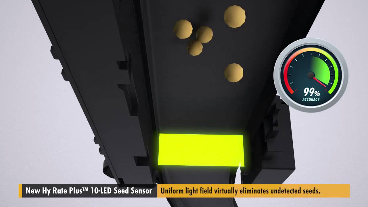
The Hy Rate Plus™ LED Seed Sensor is the sensor of choice for all seed types regardless of size, shape and seeding rate. From larger seeds such as corn to small seeds like canola, the Hy Rate Plus accurately counts seeding population during planting, providing confidence that your row units are working properly and seeds are being placed for opt...
cedar mountain
feral pivot
I powered it with a cc psu because every time I connected the adc power led on t...
Sounds like your ADC module might be fried, then.
livid osprey
woeful knot
Question - how fast it can detect movement, and is it gonna be sufficient for co...
These breakbeams have a response time of 2ms, so I can't say they'll be super reliable for counting a large volume of seeds. Dust smaller than the receiver LED certainly won't be an issue, but small clumps of dirt may trigger false positives.
feral pivot
cedar mountain
Sounds like your ADC module might be fried, then.
I tried another one but it did same thing as soon as I connected it
cedar mountain
Any chance you're connecting them to the wrong Arduino power rail, like it's a 3.3V ADC module but you're hooking it to 5V or the raw VIN supply?
 stoic island
Hi, apologies if this is the wrong channel, but here goes. I've got a gargoyle statue that holds 2 candles and is powered by 3 AAA batteries. I'd like to toggle the lights via wifi, and so I have some D1 Minis, but I'm pretty newb with hardware still. Do I just want to treat the statue as if it were an external led to blink? Or am I completely off base
feral pivot
cedar mountain
Any chance you're connecting them to the wrong Arduino power rail, like it's a 3...
Adc is compatible with 5v and 3.3v and arduino is powered from usb so theres no chance frying it by wrong voltage
cedar mountain
feral pivot
Adc is compatible with 5v and 3.3v and arduino is powered from usb so theres no ...
Accidentally reversed positive and negative voltage? I dunno, I'm grasping at straws, but a healthy module should not cause an Arduino brownout, as it's a pretty low-current device.
woeful knot
livid osprey
These breakbeams have a response time of 2ms, so I can't say they'll be super re...
do you have some other suggestion - maybe ky-008?
feral pivot
cedar mountain
Accidentally reversed positive and negative voltage? I dunno, I'm grasping at st...
Checked twice when it happened but everything is normal can something like this can happen because of mux inside the adc?
feral pivot
stoic island
Hi, apologies if this is the wrong channel, but here goes. I've got a gargoyle s...
You can treat it like led then when you are sure the system is good you can connect it the statue to the system with a transistor
cedar mountain
feral pivot
Checked twice when it happened but everything is normal can something like this ...
Are you aware of the voltage range of the analog input to the ADS1115? From your diagram it looks like the current shunt might be at a higher voltage.
 feral pivot
With 0.01 ohm at max 0.256v with 16x gain 0.256 volt/0.01 ohm=25.6A is max current with 0.256v voltage drop across the shunt
cedar mountain
feral pivot
With 0.01 ohm at max 0.256v with 16x gain 0.256 volt/0.01 ohm=25.6A is max curr...
Yes, but what's the absolute voltage?
feral pivot
cedar mountain
Yes, but what's the absolute voltage?
Do you mean voltage between gnd and in+
cedar mountain
feral pivot
Do you mean voltage between gnd and in+
Yes.
feral pivot
I was testing it with 3.3v across gnd and in+ and 1A current through the shunt while testing the code
cedar mountain
That should be fine, then.
I'm not sure what to tell you. It still sounds like the ADC module(s) are fried, but it's unclear what originally happened to them to cause that.
feral pivot
cedar mountain
I'm not sure what to tell you. It still sounds like the ADC module(s) are fried,...
Ok thanks for the help anyways I will take look at it a bit more sometime but sometimes electronics are annoying
 sacred ivy
feral pivot
I'm trying to make a power meter with a esp32 and ads1115.When trying measuring ...
sacred ivy
feral pivot
I'm trying to make a power meter with a esp32 and ads1115.When trying measuring ...
Im gonna make a suggestion. Add in a very small capacitor in parallel with your analog input (like 10nF or so). See if that helps. But you also shouldnt be drawing that much current either.
For testing purposes make the delay between readings 1 second and see if it still has the same issue.
(or something excessively large)
feral pivot
sacred ivy
Im gonna make a suggestion. Add in a very small capacitor in parallel with your ...
I will try it but I think delays wont work because adc makes the readings automatically and then we are reading the buffer of adc I think setting the sampling rate has a lot more chance
sacred ivy
feral pivot
I will try it but I think delays wont work because adc makes the readings automa...
That too. Certain sample rates only work for a small range of clock rates, maybe its out of wack. But it shouldnt have changed though if all you are doing is switching channels
feral pivot
Find out why my adc were frying. find a forum post about same question on texas instruments forum and he says problem was ads1115 wasnt designed to take a floating input. But I didnt understand how a connected input is a floating input?
north stream
I think it's referring to a voltage that has a component significantly different from the ground reference. You might have more luck with low side current sensing, if your application supports it.
median mica
I’d like to use Microchip/Atmel Studio to program chips. Can anyone recommend a programmer? From what I’ve read I should try to find a AVRISP mkII clone.
leaden walrus
what chips?
median mica
Oh yeah, that would make a difference. Attiny’s, Atmega’s, whatever I can get to experiment with. Maybe SAM.
I’ve used Arduino IDE to program those chips, but I’d like to move away from Arduino
 spark drum
How do I de solder a smd connector with a soldering iron?
I have my temp set to 260C
And am tryna de-solder a lipo connector off of a artemis
 livid osprey
spark drum
How do I de solder a smd connector with a soldering iron?
I have my temp set to ...
livid osprey
spark drum
How do I de solder a smd connector with a soldering iron?
I have my temp set to ...
Very carefully? If you aren’t trying to salvage the connector or the pads, you could just apply heat to the pins until it pops right off. Might melt some plastic, so don’t put your face too close.
Alternatively, you can try to get snips to clip the pins, then desolder them one by one.
Proper way would be to wick the solder or use chip quik, if you need to keep everything intact.
true spear
spark drum
How do I de solder a smd connector with a soldering iron?
I have my temp set to ...
Flux does a good job at helping the solder to flow and, if you have time, chip quik is an option.
 neon cobalt
i have 4 led's receiving power from 4 different pwm pins and they are sharing a grounded row in my bread board. Something weird is going on, when i set my analog write power to 127, only 2 led's light up, when i set the power to 128, all led's light up, whats going on?
cedar mountain
neon cobalt
i have 4 led's receiving power from 4 different pwm pins and they are sharing a ...
Can you clarify the difference in the two scenarios? You say both situations have 127. And is this on one of the four PWM pins, or all of them?
neon cobalt
oh oops
neon cobalt
cedar mountain
Can you clarify the difference in the two scenarios? You say both situations hav...
i ment that in 127, only 2 leds light up, and in 128, all 4 light up
oh i figured it out
i accidentally hooked 2 led's to a pin thats not a pwm pin
 zealous jetty
Hi all, I'm having some troubles detecting a blinking LED using a digital input... I'm using a transistor switch but it seems that it's not saturated enough to work... Am I missing something here?
 pine bramble
Current flows from ground against the arrow up to Vcc through the Base, in that transistor.
I would model it in a simulator.
pine bramble
$ 1 0.000005 10.20027730826997 50 5 50 5e-11
t 464 224 512 224 0 1 0.49122030547086204 0.5135427144553883 100 default
g 512 240 512 336 0 0
r 464 208 464 112 0 220000
w 464 112 384 112 0
R 288 112 240 112 0 0 40 4.5 0 0 0.5
r 384 112 384 208 0 470
162 384 208 384 288 2 default-led 1 0 0 0.01
g 384 288 384 336 0 0
w 464 224 464 208 0
s 288 112 384 112 0 0 false
r 592 208 592 112 0 500000
w 512 208 592 208 0
R 592 112 640 112 0 0 40 3.3 0 0 0.5
p 592 208 592 272 1 0 0
g 592 272 592 336 0 0
for:

@zealous jetty
(Open circuit on the input side)

The voltmeter represents a GPIO input.
https://tinyurl.com/yc7weg8d
Should load that circuit in the URL above.
zealous jetty
Wow thank you I was just trying to model it too. But then this doesn't seem to look too bad right? Pulling HIGH and LOW...
pine bramble
None of it looks exactly how I'd approach things but I was trying to restrict myself to what you came up with. ;)
I would be only worried about frying the GPIO pin by some assumption I've made.
zealous jetty
pine bramble
I would be only worried about frying the GPIO pin by some assumption I've made.
I think it can take 4.5V without dying but it's not recommended
zealous jetty
pine bramble
None of it looks exactly how I'd approach things but I was trying to restrict my...
Are there any other options I can use? I thought of using a comparator as well
pine bramble
I think in this role the transistor serves to permit the presence of a 4.5 VDC active circuit that won't harm a 3.3 V microcontroller's GPIO pin.
Honestly this was stretching my ability pretty far as-is. ;)
I would immediately think about level-shifting circuits.
But that NPN is probably enough, here, and they're inexpensive and usually found on-hand in your parts box.
zealous jetty
I already have this circuit soldered and wired-up but something seems to be going wrong. I'm now trying to fit in the specs of the transistors datasheet into the circuit model you provided!
pine bramble
Look at chapter 8 as well:
https://ww1.microchip.com/downloads/en/devicedoc/01146b.pdf
zealous jetty
pine bramble
I would immediately think about level-shifting circuits.
Indeed, this would be a nice option, logic convert from 4.5V to 3.V and using analog reading?
pine bramble
I selected the resistors on minimal current flow through that transistor (mainly to save on battery life).
When you mouse-over anything in that simulator (if your browser supports the sim at all) it gives typical readings your test equipment would expose.
It's based on thevenin's/kirchoff type ideas.
You must use at least 1 ohm as a resistor in any path where current would go to infinity or the sim won't even run.
That same sim has an arduino AVR variant where you can add code!
example here:
I embedded the circuit in the C/C++ source code there, and also gave the web address for the sim.
It basically reads a pb switch on Pin 8 and outputs its findings on Pin 9 (an LED monitor circuit).
Designed as push-on, push-off using a momentary contact pb switch.
zealous jetty
Wow that's pretty cool, thank you so much!
pine bramble
You're quite welcome.
zealous jetty
Will spend the rest of my day looking into this 😉
pine bramble
Yeah I was very resistant to any simulator until I found this one.
Now I'm all about it - really like it.
Use right-click on the mouse, Drag, then from the pick list, Drag All - makes things easier.
I think you press ESC to release the mouse pointer when it gets confusing.
My fingers know it but the rest of me is just guessing. ;)
 royal hare
Oh that's a nice simulator. Thanks.
pine bramble
;) isn't it. You're welcome.
The wokwi one is better for some limited use cases.
It's got a good 74HC595 shift register ready to go.
royal hare
Awesome. I'll play around with these. I haven't used simulators at all myself but I think I will now.
pine bramble
Yeah I was totally 'against them' then this thing shows up in a chat so I tried it against my better judgement.
Loved it. ;)
 lilac barn
is it possible to use audio source from pc, in order to create a music/sound reactive led strip?
cedar mountain
lilac barn
is it possible to use audio source from pc, in order to create a music/sound rea...
Sure, PCs generally have audio outputs for headphones, so you can use that signal.
lilac barn
Okay good to know, however i don't think i can write my own program for it so i'll have to find one.
Thanks
 fierce ridge
New to the NMEA standard and wanted to ask, if one is parsing the output of a GPS module, would you be able to calculate time to first fix for each satellite or only those that give lat/long coordinates?
pallid grail
@leaden walrus Hiya. You around?
leaden walrus
yep
pallid grail
Can you please review this for me? https://github.com/adafruit/Adafruit_Seesaw/pull/65 I think Limor's not around yet.

And I want to finish the guide.
pallid grail
fierce ridge
New to the NMEA standard and wanted to ask, if one is parsing the output of a GP...
Hello! Please try to avoid cross-posting in multiple channels. Post in one, and folks will see it and answer when they can. 🙂
@leaden walrus The original example was backwards from the silk. So instead of changing the silk, which she almost did, she realised we could change the software.
@leaden walrus Also, when an Arduino library gets bumped, how long before the update shows up in the IDE?
leaden walrus
not sure...maybe a daily thing
pallid grail
Ok
I mean it doesn't matter, I guess, the file already exists, I can finish the guide while it propagates
fierce ridge
.
leaden walrus
@pallid grail one cosmetic tweak
pallid grail
leaden walrus
<@!330227457296957440> one cosmetic tweak
Saw it and already fixed! Thanks!
@leaden walrus Thank you!
leaden walrus
np
spark drum
true spear
Flux does a good job at helping the solder to flow and, if you have time, chip q...
Yeah just bought a 858D Rework Station, some Flux, and Brushes to put flux onto the board and clean it and whatnot
What temp in c should I use to try and get the connectors off?
Not tryna re-use the connectors just tryna make them come off cleanly without damaging the board
true spear
spark drum
Not tryna re-use the connectors just tryna make them come off cleanly without da...
It depends on the type of solder and its age, also the flux. I have found that if it is difficult I can add a little fresh solder and get it to melt easier. As to the temp I can't tell you. Just make it hot enough to quickly melt the solder and not so hot it burns the board. It is a learning curve and I adjust the temp as needed.
spark drum
true spear
It depends on the type of solder and its age, also the flux. I have found that i...
Yeah I ended up botching it and a pin got stuck that ripped out the lining of the lipo pinhole 😂

At least it was dirt cheap this pcb
Im debating on whether or not I wanna get another of it or just make my own pcb
 grim basalt
Hello people would u mind letting me know any of the best discord server communities for the domain Computer Vision and Image Processing because I have many problems with that domain I need to solve and I need some help..
cold lagoon
Help. This is part of an PCB ive made, and the nrf24l01 doesn't work. i have no idea why (the black dots are solder pads they can be ignored)
 cedar mountain
cold lagoon
Help. This is part of an PCB ive made, and the nrf24l01 doesn't work. i have no ...
cedar mountain
cold lagoon
Help. This is part of an PCB ive made, and the nrf24l01 doesn't work. i have no ...
You'll probably need to expand on "doesn't work", since that could mean anything from "sparks and smoke came out when I powered it on" to "I'm getting a weird checksum error about every 5 megabytes of data transmitted to my home network".
cold lagoon
no sparks, no smoke, no signal from the nrf 🙂
cedar mountain
By "no signal" do you mean it doesn't respond over SPI, or you're not receiving data on the other side of the radio link?
cold lagoon
jup i cant send and i cant receive anything
cedar mountain
Sorry for being pedantic about this, but we're not mind-readers, and we don't have magic wands to make stuff work as soon as you tell us that it's broken. (And we're all volunteers, so under no obligation to help at all.) The only way through this problem is going to be a tedious troubleshooting process where you have to do most of the work and over-share information about your situation. "Here's the exact code I'm running, here's the exact error message I'm getting, here's what I expected to happen instead, here's a picture of my breadboard showing all the wire connections, here's the steps I've already taken to try to diagnose exactly where things are breaking", etc. etc. etc.
cold lagoon
ok. Both sender and receiver codes are 100% working, ive checked them with proper arduinos. The sender code just sends 444 and the receiver code displays everything, it gets. Problem is it displays nothing.
ive already retraced the traces twice and also measured if they're ok and they are.
 cold lagoon
one thing ive noticed just now, as soon as i disconnect the nrf module i get in the while (radio.available()) loop. but when its connected i don't get there anymore
 elfin gazelle
Just had read some tutorials about header files and in some they just used a header file with a class which is included in the ino file and in others they created a cpp file with the header file. Wondering what's the difference between these approaches...
cedar mountain
cold lagoon
ok. Both sender and receiver codes are 100% working, ive checked them with prope...
It's probably not your real issue, but one thing that will probably surprise you eventually is that you're using ints for your message data, but the read() and write() calls operate on bytes, so when you send a length of 1, you're actually only sending the lowest 8 bits of the 444 integer.
cold lagoon
nope thats not my problem. i get nothing not even the lowest 8 bits
elder hare
This pattern draws a bar of 4 pixels length ( PatternBarLength ) and sends it down to the end of the strip and then draws a new bar of 4 pixels and sends it down (each bar stacks ontop of each other and when the strip is full the "last bar of 4 pixels" sweeps over the entire strip and every pixels behind it gets set to "black" and it sets itself at the end of the strip and repeat! 🙂
my problem here is when i start the pattern it stops the first bar of 4 pixels 4 pixels befor the end so i have 4 black pixels at the end but once the pattern has gone a full cycle then it fills the entire strip...
hope this was clear enough, i dont see where the problem is
    virtual void draw(CLEDController& c)
    {
        CRGB* leds = c.leds();
        int size = c.size();

        const uint16_t TotalLength = size;

        static uint16_t end = TotalLength;
        static int block = 0;
        static CRGB color = 0;
        static int i = 0;

        // reset after each full sequence
        if ( block >= TotalLength / PatternBarLength )
        {
            block = 0;
            end = TotalLength;
            if ( PatternColorUse == RANDOM )
                color = CHSV( random( 0, 255 ), 255, 255 );
            i = 0;
        }

        if ( PatternColorUse == RANDOM )
            leds[ i ] = color;
        else
            leds[ i ] = PaletteMode( c, i, PatternBrightness );

        if ( i >= PatternBarLength )
        {
            leds[ i - PatternBarLength ].fadeToBlackBy( 255 );
        }

        if ( ++i >= end )
        {
            i = 0;
            end -= PatternBarLength;
            if ( PatternColorUse == RANDOM )
                color = CHSV( random( 0, 255 ), 255, 255 );
            block++;
        }
    }
It looks like you're trying to use i to count and block to address your LED block, but you're incrementing them separately. I think it would be simpler (and may solve your problem) to just have (and increment, and test) a single variable.
elder hare
so i removed block and only used i but now the pattern does not work :/
elder hare
@north stream fixed it
elfin gazelle
trying to mulitplex bounced buttons. And my code just works when I have that if statement checking if mux.read(0) is LOW and then Serial.print "Is LOW". And then it will also Serial print "Has changed" from the bounce if statement. When I remove the Serial.println from the mux if statement or the whole statement my bounce.changed() does not work anymore. ??? ```#include "Type4051Mux.h"
#include <Bounce2.h>
Bounce bounce = Bounce();
Type4051Mux mux(4, INPUT, DIGITAL, 5,6,7);
Type4051Mux mux2(3, INPUT, DIGITAL, 5,6,7);
void setup() {
// Initializes serial port.
Serial.begin(9600);
bounce.attach( mux.read(0), INPUT );
bounce.interval(5);
}
void loop() {
bounce.update();
if (bounce.changed()){
Serial.println("Has Changed");
}
if (mux.read(0) == LOW){
Serial.println("Is LOW");
}
}```
dont know if that is actually not working the way I want it to: bounce.attach( mux.read(0), INPUT );
and also this just works with the Serial.println("Is LOW"); in it. if (mux.read(0) == LOW){ if (bounce.changed()){ Serial.println("Has Changed"); } Serial.println("Is LOW"); }
elfin gazelle
So these libraries dont work together though?
leaden walrus
that'd be my guess
elfin gazelle
Okay, any hint how to multiplex bounced buttons?
leaden walrus
in general, your approach is ok, it's just the two libraries don't seem to work together
the bouncer library is reading the pin directly, not through a muxer
^^ that's what update() is relying on
elfin gazelle
So for example I will just use the mux libraray and do the bouncing without a library?
elfin gazelle
I could not try it out at the moment but would that approach just count +1 when the button is high and count +1 just the button goes Low and high again instead of doing +1 all the time the button is high?
  int buttonState;
  int bounceState = LOW;
  int count = 0;

void setup() {
  // put your setup code here, to run once:

}

void loop() {
  // put your main code here, to run repeatedly:

  if (buttonState == HIGH && bounceState != buttonState){
    count ++;
    bounceState = buttonState;
  } else if(buttonState = LOW){
    bounceState = LOW;
  }
}```hi, i couldn't get the "Adafruit 2.9" Grayscale eInk / ePaper Display FeatherWing - 4 Level Grayscale PID: 4777" to work with the RP2040. Screen just stay black
pine bramble
test file (Thinkink_gray4) is just black/white alternating in the test.
neon cobalt
whats the difference between a for loop and while loop?
 odd fjord
 forest cape
Hello guys I need a help I just begin to learn how to code. So I want to connect my dac which has i2c connection. I already set up the external pull up, do I still need to write pull up function in my code? Thank you!
north stream
forest cape
Hello guys I need a help I just begin to learn how to code. So I want to connect...
No, if you have resistors pulling up, you don't need to enable pull-ups on your I/O pins (however, it won't harm anything if you do)
 vale dew
Hey, I am using the Adafruit BNO055 with an Arduino Due. The Arduino Due has two I2C / TWI interfaces SDA1 and SCL1 are near to the AREF pin and the additional one is on pins 20 and 21. How do I tell it during the contructor that I want to use the SDA1 and SCL1 instead of pins 20 and 21. Adafruit_BNO055 bno = Adafruit_BNO055();
cedar mountain
vale dew
Hey, I am using the Adafruit BNO055 with an Arduino Due. The Arduino Due has two...
The constructor can accept an optional Wire reference for which I2C port to use, so you can pass in Wire1 for that parameter:c Adafruit_BNO055(int32_t sensorID = -1, uint8_t address = BNO055_ADDRESS_A, TwoWire *theWire = &Wire);
vale dew
cedar mountain
The constructor can accept an optional `Wire` reference for which I2C port to us...

oh wait nvm
its &Wire1
Thank you so much
pine bramble
Hi all, I happen to have the ST25DV16, I have used it with ESP8266 on Arduino, but it had errors. So now I have a Feather STM32F405, It's working fine for me, Now I need you to help me write some text on it. The library in Arduino writes a URL, but this way it doesn't work for me. I need to write a text, and I have difficulties. Could you please explain me how to write a simple text? I have looked around the library and it is not that easy, because there is no function to write text.
severe latch
Hello . I was wondering what would be the best way to create a log file on nRF52840 feather ?
I am using nRF52840 with RTC DS3231 .. so my goal is to create like a simple log file to store the time stamps and temperature for example every 10 minutes
stable forge
severe latch
I am using nRF52840 with RTC DS3231 .. so my goal is to create like a simple log...
Do you want to log to a file on CIRCUITPY, or on some external thing, like an SD card?
SD card example: https://learn.adafruit.com/data-logging-with-feather-and-circuitpython
how to write to CIRCUITPY (which is normally read-only): https://learn.adafruit.com/circuitpython-essentials/circuitpython-storage
stable forge
oh, sorry, I missed what channel we are in
severe latch
No that's totally fine ! I forgot to mention that as well
severe latch
Thank you . I saw that there is an API "InternalFileSystem" that uses LittleFS but was unable to find the right documentations for it.
https://gist.github.com/stonehippo/ffbed2f32e1813f4019ecedd22062636


Gist
Some example Arduino IDE code showing how to do various things with Adafruit nrF52 Feather BLE - Adafruit_nrf52_example.ino
stable forge
severe latch
Thank you . I saw that there is an API "InternalFileSystem" that uses LittleFS ...
what I am looking for is an example that uses the external SPI flash chip on the board and can present it as a USB drive
@severe latch This library lets you write to the SPI flash chip that is on the board: https://github.com/adafruit/Adafruit_SPIFlash
This example can expose that filesystem via USB: https://github.com/adafruit/Adafruit_TinyUSB_Arduino/blob/master/examples/MassStorage/msc_external_flash/msc_external_flash.ino
severe latch
Okay will look into this. Thank you !
 blazing crane
Looking at the sample sketches for a motor driver I bought. They use the PWM pins as output, but I'm not sure there's enough pins for my needs? Is there a reason I can't use the analog pins?
Wait, nvm. Did some Googling. I think I'm wrong 😦
livid osprey
blazing crane
Looking at the sample sketches for a motor driver I bought. They use the PWM pin...
The only issue I could potentially see is the lack of hardware PWM on those pins? If software PWM is within its means, it could work.
blazing crane
I basically need to run SPI and and the Servo library at once... It seems like there could be interference from what I've read
livid osprey
Uno?
blazing crane
I guess yeah
Using an Uno atm, then most likely switching to the smallest ATtiny I could get that suits my needs
For the final design
livid osprey
It's worth a try. I'm not sure what interference your google search came up with, but they should be fine if they have their own pins.
blazing crane
Which PWM pins work on which timer btw?
lilac rain
does anyone have some time to see why this following sketch is not lighting up my neopixel ring? the sketches are essentially two default examples merged together. https://pastebin.com/rtr0ARqb
Pastebin
Pastebin.com is the number one paste tool since 2002. Pastebin is a website where you can store text online for a set period of time.
cedar mountain
lilac rain
does anyone have some time to see why this following sketch is not lighting up m...
It looks like the testanimate() function called at the end of setup() contains an infinite loop to perform the animation forever, so it never returns and therefore loop() never gets called to do the Neopixel stuff.
lilac rain
cedar mountain
It looks like the `testanimate()` function called at the end of `setup()` contai...
wow that was fast, lol. how would I go about fixing this? i assume something with for(;;) { // Loop forever..., needs to be changed?
cedar mountain
Yeah, you would want to move the code that's performing the display animation into loop() so you end up doing one Neopixel step, then one display step, then another Neopixel step, etc.
lilac rain
cedar mountain
Yeah, you would want to move the code that's performing the display animation in...
thank you, I will mess around with it. Appreciate your quick input!
 fluid nebula
Looking for a little help with platformio programming an adafruit ItsyBitsy M0
In pio I can get it my program to compile/upload and everything looks fine, but the device stays "disconnected" (purple dotstar on the board) or in bootloader mode (green led) and does not enter the program. If i flash the same code from Arduino, it works as expected
Arduino is writing more bytes - which is strange (33736 in arduino vs 23344 in pio)
is there a setting/flag I might be missing in pio?
 wraith current
@fluid nebuladoes a manual reset after programming make it work ?
fluid nebula
nope - button presses either end up disconnected or in boot mode
wraith current
what's your .ini file look like ?
fluid nebula
[env:adafruit_itsybitsy_m0]
platform = atmelsam
board = adafruit_itsybitsy_m0
framework = arduino
build_flags = -D USE_TINYUSB
lib_deps =
  ; adafruit/Adafruit TinyUSB Library@^1.9.2
  fortyseveneffects/MIDI Library@^5.0.2
  adafruit/Adafruit BusIO@^1.11.0
  Wire
  adafruit/Adafruit FRAM I2C @ ^2.0.0
  adafruit/Adafruit Keypad @ ^1.3.0
  adafruit/Adafruit NeoPixel @ ^1.9.0
  adafruit/Adafruit SSD1306 @ ^2.4.6
  adafruit/Adafruit GFX Library @ ^1.10.12
  olikraus/U8g2_for_Adafruit_GFX @ ^1.8.0
  pfeerick/elapsedMillis@^1.0.6
  adafruit/Adafruit DotStar@^1.2.0
(was confused if i needed to have tinyusb in lib_deps, but it doesnt seem to matter either way)
wraith current
hmm, that's really weird that ardu puts 10k more data on there.
fluid nebula
10K that makes it work! LOL
wraith current
sorry, i have no idea. did you try doing pio clean ?
fluid nebula
yeh... trying to load an example (arduino-blink) right now and it is grabbing some toolchain thing
perhaps something is/was missing in my install
thanks tho!
fluid nebula
@wraith current I got it to work by adding lib_archive = no
don't understand why yet, but at least it works 🙂
severe latch
Hello. I was checking the LittleFS library and found another one "InternalFileSystem" which is dependent on Little FS. And from what i've read is that InternalFileSystem API is a higher-level abstraction and easier to work with (it is a wrapper around little FS)
However, is it possible to append while dealing with such files ? I wasn't able to find any function that would allow me to append data on an already created file. I only saw Read/write functions. Am I missing something ?
https://github.com/adafruit/Adafruit_nRF52_Arduino/tree/master/libraries/InternalFileSytem/examples

GitHub
Adafruit code for the Nordic nRF52 BLE SoC on Arduino - Adafruit_nRF52_Arduino/libraries/InternalFileSytem/examples at master · adafruit/Adafruit_nRF52_Arduino
cedar mountain
severe latch
However, is it possible to append while dealing with such files ? I wasn't able ...
With a quick glance at the code, it looks like opening an already-existing file in the writing mode will append to it by default.
severe latch
Oh okay great ! Thank you EdKeyes.
 deep steeple
I recently came into possession of a bag of random electronic bits and bobs one of which was a Giant Plus 2.5" LCD Screen (LM1322A02-1B) is there any place to find a control board/adapter board for that kind of thing or is it not really worth trying?
cedar mountain
If it's exactly what you need for a project and you can't find any other displays that would suit, you can probably find a driver board for it. However, for the same amount of money and less effort you can probably just buy a new display which is closer to what you actually want and comes with full documentation and tutorials. (You might be able to tell that I'm not a fan of dumpster-diving for electronics, heh heh.)
deep steeple
cedar mountain
If it's exactly what you need for a project and you can't find any other display...
That's fair, I usually tend to just loot more for stuff like buttons and lights etc. part of being on a college student budget. My 3 home servers (a mac pro and 2 dell workstations) for example were ones I got from my schools tech trash pile
 autumn timber
Hello, I´m doing a project where you use a fingerprint sensor to open a door using a solenoid lock and a fingerprint sensor and for a safety measure i´m also using a keypad 4x4 and I was wondering if by code you could block the fingerprint sensor and use the keypad
cedar mountain
autumn timber
Hello, I´m doing a project where you use a fingerprint sensor to open a door usi...
Sure, in general. The code is the thing reading the fingerprint sensor, so it can decide what to do with it. It could ignore the result, or just not read the sensor in the first place if it's blocked.
sacred ivy
I always come back to this out of curiosity but is there a 32 Bit processor that Arduino supports and is in a TQFP package? Preferably in a 32 pin package as well. Im not too familiar with the Arduino eco system.
livid osprey
sacred ivy
I always come back to this out of curiosity but is there a 32 Bit processor that...
ATSAMD21, perhaps?
sacred ivy
livid osprey
ATSAMD21, perhaps?
I'll look into this, thanks 🙂
livid osprey
leaden walrus
^^ digikey search for 32 bit / 32 pin TQFP / available
samd21 would be a good basic choice unless you have some specific requirements
here's the core FWIW, might help to look through variants, etc
https://github.com/arduino/ArduinoCore-samd
sacred ivy
Nah, more of a curiosity thing. I always like to compare things
livid osprey
STM32 has some options as well. https://www.mouser.com/ProductDetail/STMicroelectronics/STM32L010K4T6?qs=PqoDHHvF64%252BA8yN3WOJbRw%3D%3D
sacred ivy
So, I wonder if they will start supporting Microchips PIC32CM line (which uses Cortex M0+). I just got an email about it today, hence why I was curious about whats out there for 32 bit support. I always like integrating "naked" uC's in my designs due to size.
For the price of their "Curiosity Board" I was also wondering what boards were around the same price. I know with Arduino I'll easily get more community support but with PIC, Im kind of on my own 😅
livid osprey
I'm sure if this line takes off, someone will eventually write an Arduino core for it. Seems possible, but someone will have to invest the time to do so. Kinda nice to see a 5V 32-bit MCU, something that has been missing in the present-day MCU ecosystem...
Flash is pretty small, but the peripherals look pretty appealing...
sacred ivy
Yea I had a quick look and the one thing that sticks out to me is a built in Quadrature encoder
Microchip was always good with their peripherals
severe latch
cedar mountain
With a quick glance at the code, it looks like opening an already-existing file ...
It seems like it does not work his way. If I try to open an already existing file in write mode the new data will not get appended or overwritten.
cedar mountain
severe latch
It seems like it does not work his way. If I try to open an already existing fil...
Bummer, sorry for misleading you.
severe latch
Not at all ! I appreciate you for sharing your thoughts with me
Still need to figure out how to append to a file though haha
severe latch
Any suggestions how to log data on feather nRF52 without using external SD card ?
cedar mountain
severe latch
Any suggestions how to log data on feather nRF52 without using external SD card...
Depends on how much data. You could store some on the nRF52's flash, for instance.
stable forge
sacred ivy
So, I wonder if they will start supporting Microchips PIC32CM line (which uses C...
PIC32CM is rather thin on RAM and flash: 16KB max RAM, 128KB max flash
sacred ivy
stable forge
PIC32CM is rather thin on RAM and flash: 16KB max RAM, 128KB max flash
To me thats a lot, but Im used to working with 512 to 1024 bytes of ram and 5k Program memory 😅
stable forge
seems low compared to SAMD21 to me. I looked at these originally from a CircuitPython point of view, and that doesn't work at all.
maybe pricing is good
sacred ivy
stable forge
seems low compared to SAMD21 to me. I looked at these originally from a CircuitP...
How come? Not enough ram/flash to run it?
stable forge
SAMD21 is really minimal for circuitpython, and that's 32kB and 256kB
sacred ivy
Thats why I figure the arduino core would be good
stable forge
it will be intresting - should be a relatively easy port
sacred ivy
https://www.microchip.com/en-us/development-tool/EV10N93A
Its on sale for 15% off, so $16
A little higher priced for the board compared to most
I guess the main question is: What else is around that price point to make it worth it and is already supported? the IC is $3 each.
stable forge
yes, are they trying to switch people off of SAMD, or off of PIC32?
sacred ivy
Or break into the SAMD market more
My only grievance with microchip is that I wish their products were supported more with open source stuff. But thats not their fault. I do wish I had the time and knowledge to port the few PICs I use over to Arduino.
north stream
That's why I abandoned PIC for AVR.
 sly scarab
Hi everyone I just bought a 8 channel sunfounder relay board and it appears that setting the pin connected to one of the relays is what turns the relay on
Does anyone know why it’s low and not high to turn on the relay?
 rough torrent
Maybe the relay for some reason is pulled high by default? Or maybe you are connecting to the NC and COM terminals?
sly scarab
I’m not sure because I thought low would mean 0 a volt output and the other pins for the relays do not have a connection at all and they’re still off
 heady wharf
hey, what URL do i add in the board manager in the arduino IDE to get the latest ESP32 board? Version 2.0.2
wraith current
@heady wharfmaybe try the devlopment version https://raw.githubusercontent.com/espressif/arduino-esp32/gh-pages/package_esp32_dev_index.json
heady wharf
@wraith current yeah thanks, figured out i needed to delete my old 1.0.6 version otherwise it didnt work
north stream
sly scarab
Does anyone know why it’s low and not high to turn on the relay?
There are a few possible reasons. In the old days, TTL logic could pull low with more current than it could pull high. Also, open collector (and open drain) output gates can only pull low. It avoids issues with different supply voltages as well, and there are some situations where it's just more practical to pull to ground than to some other voltage.
 proper forum
The microchip page for the itsybitsy m0 chip seems to suggest there are up to 6 uarts available on the m0, how would I go about accessing these through the Arduino Environment?
Additionally if anyone has experience interfacing the tbs crossfire nano rx with an arduino any tips/resources would be appreciated
proper forum
Does it require changes to adafruit-samd-1.7.9 ▸ variants ▸ itsybitsy_m0 ▸variant.cpp?
true spear
@proper forum You might try the Adafruit forums to get an answer in more detail.
proper forum

Adafruit Learning System
Get more high speed serial commports without bitbanging
Just found this which might be useful
cold lagoon
Hi im just playing around with some NRF24L01 and i wonder why i only receive ReceivedMessage[0] and instead of ReceivedMessage[2] just 0?
And also what those numbers (marked in red) are for?
 livid osprey
cold lagoon
Hi im just playing around with some NRF24L01 and i wonder why i only receive `Re...
livid osprey
cold lagoon
Hi im just playing around with some NRF24L01 and i wonder why i only receive `Re...
The number indicates the number of bytes to be sent/read. If you only send and read one byte, you're only going to receive a single value of 0-255. If you want to send and receive 4 ints, you'll need to change that number to allow transmission of 8 bytes.
cold lagoon
ahh thank you
neon cobalt
int redPin=8;
int greenPin=9;
int bluePin=10;
String myColor;
String msg="What Color do You Want?";
void setup() {
  // put your setup code here, to run once:
  Serial.begin(9600);
  pinMode(redPin, OUTPUT);
  pinMode(greenPin, OUTPUT);
  pinMode(bluePin, OUTPUT);
}

void loop() {
  // put your main code here, to run repeatedly:
  Serial.println(msg);
  while (Serial.available()==0) {

  }
  myColor=Serial.readString();
  Serial.println("working pls");
  Serial.println(myColor);
  if (myColor=="red"){
    Serial.print("worked");
    digitalWrite(redPin,HIGH);
    digitalWrite(greenPin,LOW);
    digitalWrite(bluePin,LOW);
  }
  if (myColor=="green"){
    Serial.println("green chosen");
    digitalWrite(redPin,LOW);
    digitalWrite(greenPin,HIGH);
    digitalWrite(bluePin,LOW);
  }
  if (myColor=="blue"){
    Serial.println("blue chosen");
    digitalWrite(redPin,LOW);
    digitalWrite(greenPin,LOW);
    digitalWrite(bluePin,HIGH);
  }
  if (myColor=="off"){
    Serial.println("off chosen");
    digitalWrite(redPin,LOW);
    digitalWrite(greenPin,LOW);
    digitalWrite(bluePin,LOW);
  }
}
when i run it and type in my serial monitor, for example "red", it would say "working pls" and the word the person entered "red", but nothing happens, because nothing is printed inside the if statement. Why is this not working. No errors, and i made sure to type in all lower cases.
 stoic scroll
Hi all, I am trying to use a NeoPixel Led instead of blue led on the Feather nrf52840 to blink when scanning and stay blue on when connection is made. I am using Bluefruit.connected() to manually do this in a loop. I am wondering if the API provides a better way to do this using callback function.
cedar mountain
neon cobalt
```c++
int redPin=8;
int greenPin=9;
int bluePin=10;
String myColor;
String msg=...
An easy way to diagnose this would be to print out the value of myColor that you're getting. I suspect that readString() is returning just the first character without waiting for the full line to finish being typed. You might need readStringUntil('\n') or something like that instead.
proper forum
proper forum
Additionally if anyone has experience interfacing the tbs crossfire nano rx with...
I managed to get an additional serial port configured on my itsybitsy m0 and get it to reliably read crsf (TBS Crossfire) readings from my TBS Nano RX 😄 https://github.com/AaronLi/FPV-RC-Car/blob/main/arduino/crsf_test/crsf_test.ino

GitHub
Contribute to AaronLi/FPV-RC-Car development by creating an account on GitHub.
wraith current
@proper forum woah. Couldnt figure out if I was in adafruit, Arduino, or Bardwell discord for a sec.
 smoky sun
Hello yall, I'm working with this lilygo t2 esp board that has a built in 1331 display and sd card. I can't seem to get both working simultaneously. Appreciate any feedback.

My sample code
When I initialize the SD card with simple SD.begin it works but the display doesn't. If I try specifying the CS pin on SD.begin it stops working but the display starts working.
I see in the pinout diagram the display and sd share a few pins, it it possible to still use these at the same time?
cedar mountain
smoky sun
I see in the pinout diagram the display and sd share a few pins, it it possible ...
I'd see if you can find a board schematic to reference. The pin assignments in that graphic look somewhat weird, since IO15 is used for MOSI on one device but CS on the other, for example. So I suspect the pin numbers are a little scrambled versus how it's actually wired up in reality.
Yeah, the schematic seems to use a completely different set of pins for the SD Card.
 smoky sun
Interesting, I'll take a look at the schematic and try adjusting the pinouts. Thank you!
 lunar patio
Hello! I’m currently making my own MIDI controller out of old organ pedals using my own fork of Gustavo Silviera’s widely used code. It has 12 foot switches which are normally open, and there will be 3 additional buttons that are normally closed (NO stomp switches are rare and expensive). Would anyone be willing to show me how to set certain pins to have an inverted output in the code?

GitHub
Contribute to marcellocirelli/DIY-Midi-Controller-full development by creating an account on GitHub.
I’ve tried experimenting in the B_BUTTONS and Z_SETUP tabs to no avail. The pins in question would be A0, A1, and A2
wraith current
@smoky suncan you go back and forth between the display and the sd card ? eg. can you display something, then breakdown the display connection, then start the sd connection. does the image remain on the display when doing this ?
proper forum
My ItsyBitsy M0 is giving me weird behaviour. When I run it off battery (6v from ESC on BAT pin) it seems to hang, not reading rc inputs but still producing a valid PWM signal for the esc and steering servo. It's not until I plug it into my computer (while still on battery) and unplug it until it starts working as expected. Are there any ideas why this could be happening?
The code does use Serial and Serial.print/ln/f but I don't have any while(!Serial) in my code
would the behaviour be a result of an exception in the code?
cedar mountain
proper forum
The code does use `Serial` and `Serial.print/ln/f` but I don't have any `while(!...
It sounds like it's hitting one of your printf calls and blocking until the serial port is fully initialized. Just skipping the while-loop check won't necessarily make them work.
You might need to do something likec if (Serial) Serial.printf(...);
proper forum
cedar mountain
You might need to do something like```c
if (Serial)
Serial.printf(...);```
I tried removing all of the statements involving Serial
GitHub
Contribute to AaronLi/FPV-RC-Car development by creating an account on GitHub.
still the same behaviour
It's weird because it seems like it's kind of functioning but won't read the RC input
it's hard to debug since I want it to work ideally with no usb connected at all
could it be a power issue, or resource allocation issue?
On the itsybitsy I'm using 2 PWM outputs and a 420,000 baud UART on SERCOM 3
Update: Maybe changing from 400k baud to 420k did some magic? That or charging the main nimh battery a little more
pine bramble
The baud rate chosen may be too ambitious.
proper forum
I don't get to choose the baud rate, it's the rate my rc receiver outputs
elder hare
im using ESP32, is it better to use AsyncWebServer then WebSocketsServer ?
safe shell
depends on the use case, they use different prorocols
proper forum
elder hare
im using ESP32, is it better to use `AsyncWebServer` then `WebSocketsServer` ?
AsyncWebServer is for serving websites, WebSocketsServer gives you a continuous channel for sending data
elder hare
@proper forum thanks for that info
safe shell
you might want to look at MQTT also
elder hare
@safe shell ill do that
proper forum
proper forum
On the itsybitsy I'm using 2 PWM outputs and a 420,000 baud UART on SERCOM 3
Upd...
continuing this saga:
It seems like if I try to call too many draw commands on my frsky pixel osd (connected to Serial1 at 115200 baud) the pwm going to my servo and esc cuts off. At least that's my conclusion since I'm using pin 13 as one of my pwm outputs and the LED attached to it turns off and the ESC starts beeping
cedar mountain
proper forum
continuing this saga:
It seems like if I try to call too many draw commands on m...
Normally a PWM pin would be driven by a timer that would run indefinitely on its own, no matter what other software was doing. Any chance your code is crashing and resetting the whole CPU?
proper forum
it's possible
maybe the OSD doesn't like drawing more than 1 line at a time
will have to look into it
 quaint cloak
is it possible to send files using lora connected to arduino and sd card module?
proper forum
quaint cloak
is it possible to send files using lora connected to arduino and sd card module?
Yes, unless there’s already a protocol its up to you to figure out what messages to send tho
quaint cloak
Sorry how do I do that?
for the messages it looks like this
uint8_t data2[sendingData.length()];
sendingData.toCharArray(data2, sendingData.length());
rf95.send(data2, sizeof(data2));
rf95.waitPacketSent();
but how do I change it for a file
safe shell
small files I hope 😉
cedar mountain
LoRa packets have a maximum length, so for a file of any significant size, you're going to have to invent a protocol to split up the file, probably sending it with a header like "part 1 of 12" or something like that so the other side can correctly reassemble it.
safe shell
252 bytes I think
quaint cloak
safe shell
252 bytes I think
oh no i think it is from 300~500 bytes
quaint cloak
cedar mountain
LoRa packets have a maximum length, so for a file of any significant size, you'r...
btw how would I sent it? convert the file into char array?
cedar mountain
quaint cloak
btw how would I sent it? convert the file into char array?
Typically if you read the file into memory, it would already be a char/byte array.
quaint cloak
I'm reading from the sd card using the sd card library
cedar mountain
quaint cloak
I'm reading from the sd card using the sd card library
The read(buffer, length) function will read a section of the file into memory, for example.
quaint cloak
thank you very much!
quaint cloak
btw, if I'm using multiple spi devices, what would I need to change to enable for two of them to function at the same time?
cedar mountain
They would need separate chip-select (CS) pins, which you would specify in initializing the SPI device. They wouldn't technically function "at the same time" on the same bus, but you can access them both in your code.
quaint cloak
cedar mountain
The `read(buffer, length)` function will read a section of the file into memory,...
for the read function
I mean in the 256 bytes
cedar mountain
You can use the length parameter to only read pieces of it at a time.
cedar mountain
It keeps your position in the file, so the next read() call would continue from where it left off.
You can also use seek() to jump to a particular position if you need to.
quaint cloak
thanks!
 ashen drum
does anyone have experience with gyros and soundmodules like the DFPlayerMini? I want to buil the sound Module for a lightsaber, but i´ve never worked with anything like an arduino before. Now i have a Nano 3.0 and the other two parts. Any help would be great
severe latch
stable forge
what I am looking for is an example that uses the external SPI flash chip on the...
Sorry for bringing this up, I just have a question regarding the libraries provided to write on SPI/QSPI flash. So it seems like the libraries are using FAT system right ? but is it safe against data corruption and does it implement any wear leveling ?
stable forge
severe latch
Sorry for bringing this up, I just have a question regarding the libraries prov...
it is no safer than regular FAT on a USB drive, and it does no wear leveling
the advantage is that it is just a pass through from USB Mass Storage, since the host knows how to deal with FAT
pallid grail
@leaden walrus Ping me when you're around. I am confused about a thing. I'll ask Limor if she shows up, but she's not around yet, so I figure ask you if you show up before she does. I'm sure I'm missing something incredibly obvious, but I'm not going to waste any more time on looking for it.
leaden walrus
@pallid grail ping
pallid grail
leaden walrus
<@!330227457296957440> ping
ohai.
severe latch
stable forge
the advantage is that it is just a pass through from USB Mass Storage, since the...
So I think the little filesystem is better but that one is used only to write on the nRF52840 internal flash maybe ?
pallid grail
@leaden walrus Ok, this example uses setTrimOffsets and getTrimOffsets, and I can't figure out where the offset functionality is coming from. https://github.com/adafruit/Adafruit_ADXL375/blob/26a9374aa6e6081fcd831a8eff96e73935cbaaee/examples/offsets/offsets.ino#L40
Or is it simply doing math in the example?
pallid grail
OH SERIOUSLY?! I searched through that multiple times.
leaden walrus
pallid grail
Thank you. Sorry. Heh.
leaden walrus
^^ that's where the inheritance is set up
pallid grail
I knew it was using the other lib
But I searched in the other lib too and came up empty
leaden walrus
how'd you search?
pallid grail
find in page in the browser.
It's not filtered down to "whole words" or anything.
so I don't know why it didn't pop on offset.
stable forge
severe latch
So I think the little filesystem is better but that one is used only to write on...
littlefs is possible, but then it can't be exposed over USB. I don't know of any translation library that maps FAT operations to littlefs. It's very tricky because the FAT operations are at the block level, and are done by the host. You could consider using an SD card instead, which does wear leveling invisibly.
pallid grail
Been working for finding everything else I've been looking at, so who knows.
leaden walrus
yah. weird. you were searching 343 not 375?
stable forge
in practice I have not actually heard of anyone wearing out internal flash on our microcontroller boards. But often for logging large amounts of data they will use an SD card
pallid grail
Yeah... wait... I was searching something other than 375, but now I'm wondering if there's another 34x one, and I search that. 345 maybe.
Oops. That's probably it.
I was looking at 345 I bet.
Which also uses 343 I bet.
hmm maybe not.
But still, no offsets in that.
So yeah. I was in the wrong lib.
leaden walrus
oh well. explains it at least. yah, there are several 34x libs
pallid grail
The CP 34x library starts with 345, so I assumed that's what this was using.
Mah bad.
Thank you for getting me past my facepalm.
leaden walrus
np
severe latch
stable forge
in practice I have not actually heard of anyone wearing out internal flash on ou...
Okay I see. Thank you so much for all the information
 waxen hawk
Hey could I get advice in writing for spi protocol. I’ve read the data sheet on what registers to clear,set, and to retrieve and send data. I am not sure how to initiate communication with secondary or “slave” device (don’t know if it is still appropriate to use that term) because I cannot find sample code for initializing protocol.
livid osprey
waxen hawk
Hey could I get advice in writing for spi protocol. I’ve read the data sheet on ...
The examples from https://www.arduino.cc/en/reference/SPI should have some examples on how to communicate with an SPI device using low-level SPI commands.
Open-source electronic prototyping platform enabling users to create interactive electronic objects.
 white bloom
Hi everyone,
I'm attempting to put together a voice modulator roughly using this guide: https://learn.adafruit.com/wave-shield-voice-changer. I've also been using a couple of YouTube videos for reference/sanity checking: https://www.youtube.com/watch?v=YNH4lx5vKac https://www.youtube.com/watch?v=ivkczjoOXHc. The main differences to the guide being using headphones (for testing) and I'm powering the whole thing off of a 9v battery.
I've put it all together today, but can only hear a buzzing/interference sound. I'm pretty sure I've assembled the shield correctly as adjusting the volume pot adjusts the output volume, and adjusting the pitch pot does change the pitch of the output. I'm just not getting anything that sounds like the sounds in the room from the microphone. Touching the silver circular section of the microphone also changes the sound of the output too, so it's getting something from it at least. Below are some photos of both sides of the shield and a video with the sound - ignore the pop at once point, that is from the amplifier it's plugged into. Do let me know if you'd like to see close ups of any of the wiring! Oh, it's not really an issue for me either but for some reason neither of the LEDs are lighting up either. I didn't find any information about what voltage was recommended for those though so not really surprised, but would be nice to fix if possible!
https://i.imgur.com/auOfpDK.jpg
https://i.imgur.com/auOfpDK.jpg
https://i.imgur.com/pEFCyWq.mp4
Thanks for your time!
 waxen hawk
livid osprey
The examples from https://www.arduino.cc/en/reference/SPI should have some examp...
waxen hawk
livid osprey
The examples from https://www.arduino.cc/en/reference/SPI should have some examp...
Oh thanks. But I am going to do with pure C without using any libraries. it seem to be calling beginTransaction(). Perhaps I should look in the source code of that.
livid osprey
waxen hawk
Oh thanks. But I am going to do with pure C without using any libraries. it seem...
Oh, are you looking to build an SPI application in C? https://en.wikipedia.org/wiki/Serial_Peripheral_Interface#Operation has the typical sequence of data transfer over SPI. The general flow of things is the chip select for the target device is brought low, then the clock begins pulsing for bidirectional data transmission.
The Serial Peripheral Interface (SPI) is a synchronous serial communication interface specification used for short-distance communication, primarily in embedded systems. The interface was developed by Motorola in the mid-1980s and has become a de facto standard. Typical applications include Secure Digital cards and liquid crystal displays.
SPI d...
waxen hawk
livid osprey
Oh, are you looking to build an SPI application in C? https://en.wikipedia.org/w...
I see. I guess is how do I start send data from primary to secondary. Do I just need to write the data into a designated buffer?
I.e.
command to turn on led
config bit = 1
in/out bit = 1
....
how would i send this bit array to tell the secondary device to turn on led?
The wikipedia explains how the protocol works but not necessarily how to do it c-wise. I guess there's bit banging code but I don't want to do that.
livid osprey
white bloom
Hi everyone,
I'm attempting to put together a voice modulator roughly using thi...
Can you check the wiring of your mic amplifier? The image is a bit hard to follow, especially since it's wired in all red, but I believe your GND and OUT wires might be wired to the wrong pins...
livid osprey
waxen hawk
I see. I guess is how do I start send data from primary to secondary. Do I just ...
I'm no C expert, sorry. I would think you would use a buffer of some sort, but I don't know the details there to help much.
white bloom
livid osprey
Can you check the wiring of your mic amplifier? The image is a bit hard to follo...
Aha, just realised ground is to 0 and out is to ground - that's probably it! Thanks (VCC is to 3V which I think is correct)
Hopefully that won't have broken anything
waxen hawk
livid osprey
I'm no C expert, sorry. I would think you would use a buffer of some sort, but I...
Ah thats okay. The wikipedia link was super helpful! Had a link to another person blog. Thanks!
 sage wyvern
Hi
white bloom
Anyone know any good 3D printable arduino cases that have room for some extra shields and bits on top but are still enclosed?
vivid rock
are you talking about arduino uno formfactor?
vivid rock
I'd search thingiverse. This, in particular, looks promising: https://www.thingiverse.com/thing:64008
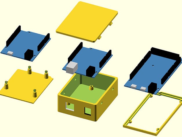
This is a library of OpenSCAD modules for mounting Arduino boards. It has modules for creating enclosures, bumpers, mounting holes, punch out holes for jacks like USB and power and board dimensions. If you are making a custom enclosure or are mounting an Arduino board to a larger project this should make it easier.
Included is an example scad fi...
vivid rock
yes, it is 😦
this might also work: https://www.thingiverse.com/thing:1673549

This two-part enclosure houses a battery pack and Arduino + motor shield board stack. Designed for student robot design projects, it gives you access to the motor screw terminals while keeping the rest of the electronics protected. The board stack screws to the lower half, which holds a 6 AA cell battery pack. The top cover snaps into place. ...
white bloom
That looks pretty good
Think I might make a custom lid for this that has the room I need actually

When you do your Arduino DIY projects, it is good to have a case for them.
This is easy to print case for Arduino UNO or Leonardo.
It is designed to print without support, there are no brigdes as well.
Editable OpenSCAD files:https://github.com/zygmuntw/3D-Printed-Case-for-Arduino
If you would like to edit this model or make something simi...
Should be able to use the stock base and then use the lid measurements to make my own version
 bronze crane
Hey everyone! I need some help to get AC current readings with ACS712, ADS1015 and ESP32 microcontroller. I am not getting expected current values.
My Connections:
ACS712:
Vcc: 3.3v
GND: GND of ESP32
OUT: A0 of ADS1015
ADS1015:
Vdd: 5v (ESP32's Vin Pin)
GND: GND of ESP32
SCL: GPIO22 of ESP32
SDA: GPIO21 of ESP32
ADDR: GND Pin of ADS1015
ALRT: No connection
A0: Output of ACS712
ESP32's GPIO35 is connected to OUT of ACS712.
Here's my Code: https://pastebin.com/N7RcFXR0
If I connect a 200W bulb I get current to be just 0.12A instead of about 0.8A
Outputs:
// Without any load
Current: 0.00
AIN0: 535  1.61V
ESP32_AIN0: 1866  0.00V

// With 200W load
Current: 0.13
AIN0: 516  1.55V
ESP32_AIN0: 1820  0.00V
Pastebin
Pastebin.com is the number one paste tool since 2002. Pastebin is a website where you can store text online for a set period of time.
If I connect both ADC & Current sensor boards to 5v I get 0.3A
elder hare
So i have 2 led strips connected now! if they both are running the same pattern they share "settings" but if i make 1 take "Solidcolor" and the other "TheaterChase" it works fine! what am i doing wrong? is it because im not making a "new class object" since they share or what is going on?
i want to be able to set same pattern on 2 strips and have them NOT share settings
my entire project : https://github.com/MythicalForce/MNC/
files controller settings and ofcourse main.cpp

GitHub
Contribute to MythicalForce/MNC development by creating an account on GitHub.
livid osprey
bronze crane
Hey everyone! I need some help to get AC current readings with ACS712, ADS1015 a...
200W bulb will only use 200W if you use it at its expected voltage. Non-LED lights are usually a resistive load, meaning resistance is (relatively) fixed, and current is proportional to voltage. What kind of a test setup are you measuring?
livid osprey
elder hare
So i have 2 led strips connected now! if they both are running the same pattern ...
From a cursory glance at the code, a lot of objects are referenced by pointers, so my suspicion would be an overlapping pointer definition reading the same part of memory?
I don't know if you have independent pointers for pattern and settings, but if you're putting your settings pointers in your patterns, you may end up with two patterns that overwrite each other's settings pointers.
elder hare
@livid osprey
std::vector<Settings> settings { {}, {}, {}, {}, {}, {}, {}, {}, {} };

    #if NUM_CHANNELS >= 1
    strand1.updatePatternSettings(*strand1_cled, settings[0]);
    #endif
    #if NUM_CHANNELS >= 2
    strand2.updatePatternSettings(*strand2_cled, settings[1]);
    #endif
    #if NUM_CHANNELS >= 3
    strand3.updatePatternSettings(*strand3_cled, settings[2]);
    #endif
    #if NUM_CHANNELS >= 4
    strand4.updatePatternSettings(*strand4_cled, settings[3]);
    #endif
    #if NUM_CHANNELS >= 5
    strand5.updatePatternSettings(*strand5_cled, settings[4]);
    #endif
    #if NUM_CHANNELS >= 6
    strand6.updatePatternSettings(*strand6_cled, settings[5]);
    #endif
    #if NUM_CHANNELS >= 7
    strand7.updatePatternSettings(*strand7_cled, settings[6]);
    #endif
    #if NUM_CHANNELS >= 8
    strand8.updatePatternSettings(*strand8_cled, settings[7]);
    #endif
 modern nexus
Would anyone know how to convert a sketch written for RGBW neopixels to RGB only? I've managed to get it working on the RGB pixels but it's very dim and I don't know what needs to be edited to change the brightness. https://github.com/LuckyResistor/CandleDecoration/blob/master/CandleV1.ino
GitHub
The firmware for a simple RTC based candle decoration light, using Trinket M0, DS3231M RTC and a Neopixel ring. - CandleDecoration/CandleV1.ino at master · LuckyResistor/CandleDecoration
livid osprey
modern nexus
Would anyone know how to convert a sketch written for RGBW neopixels to RGB only...
There are a lot of RGB-to-RGBW conversion functions and libraries out there, but the reverse isn't as common. The primary reason for this is the colorspace for RGBW is much larger than that of RGB, so your colors may change in the process of downgrading to RGB.
That being said, if you're not super selective with your colors, you can certainly mess around with a formula you like. The process of converting RGBW to RGB would likely look something along the lines of defining a function that takes your RGBW input and converts it to an RGB output. Then, whenever your code calls for an RGB color, you can call rgbw2rgb(color), or whatever you decide to name it.
The conversion function itself, on the other hand, is something you may have to experiment with a little. I'll throw a haphazard basis-less pseudocode function for you to look at, so you can design your own conversion function to look the way you want...
uint32_t rgbw2rgb(uint32_t rgbw)
{
  uint8_t rIN = (rgbw >> 24) & 0xFF;
  uint8_t gIN = (rgbw >> 16) & 0xFF;
  uint8_t bIN = (rgbw >> 8) & 0xFF;
  uint8_t wIN = rgbw & 0xFF;

  float whtRatio = 0.5;
  uint8_t rOUT = (rIN + (wIN * whtRatio))/(1+whtRatio);
  uint8_t gOUT = (gIN + (wIN * whtRatio))/(1+whtRatio);
  uint8_t bOUT = (bIN + (wIN * whtRatio))/(1+whtRatio);

  uint32_t rgb = (rOUT << 24) + (gOUT << 16) + (bOUT << 8);
  return rgb;
}
This is exactly what I needed, thank you! I'm just trying to make a candle like effect for the Magic candle from Encanto and certainly don't care about color accuracy. The rainbow version is already working great.
 rough torrent
CRC32 is 0xCB05543B
Took 2.90s to parse 757.55 kB (average 260.77 kB/sec)
CRC32 is 0x3EF7AE42
Took 0.70s to parse 173.47 kB (average 246.05 kB/sec)
anyone have any ideas on how to speed up reading? ESP32 reading off Adafruit breakout board connected to SD card at 10MHZ spi clock with SdFat (anything above doesn't work presumably cause of my breadboard spaghetti wiring)
it's reading byte by byte (although sd library should be buffering it with it's 512byte block buffer and i'm reading sequentially) and doing character comparisons to check for page boundaries for my "ebook" reader while also doing a CRC32 for it
cedar mountain
The first rule of performance optimization is to measure what's really going on. If possible you should try to profile pieces of the code to see what's taking up the majority of the time... could be the SD access, could be the per-byte read function overhead, or could be something in the page-boundary or CRC logic.
But as described you generally should be able to get pretty close to the underlying SPI speed minus a little file-system overhead, so maybe about 4x faster than you're seeing now.
 hollow flint
hey all, does anyone know of a library to enable differential ADC readily in arduino for the SAMD51, like does it well for the SAMD21 https://github.com/Molorius/ATSAMD21-ADC#void-analogreference2uint8_t-ref

GitHub
Functions for many of the ADC capabilities of the ATSAMD21 series. - GitHub - Molorius/ATSAMD21-ADC: Functions for many of the ADC capabilities of the ATSAMD21 series.
bronze crane
livid osprey
200W bulb will only use 200W if you use it at its expected voltage. Non-LED ligh...
Its an filament bulb. Basically Bulb connected to mains with the Current sensor in series. The same setup works with ESP32's ADC. I want to test it out with ADS1015 as the internal ADC of ESP32 is pretty bad.
 elfin thorn
Quick question about the Clue and the digital GPIO pins... I see a bunch of analogue pins listed in the diagram, does that mean all other pins are digital? I'm trying to connect the Clue to a AS7265X Spectrometer (I2C) in which the additional Interrupt pin normally goes to Pin 3 on an Arduino. Thanks!
solemn cliff
elfin thorn
Quick question about the Clue and the digital GPIO pins... I see a bunch of anal...
all the pins can do digital, only the analog pins can do analog
you can tie your interrupt to any pin
elfin thorn
Groovy... Thank you!
severe latch
Hello everyone. I am trying to put my nRF52840 in sleep mode and I saw that there is the waitForEvent() function. However after going through several github discussions I couldn't figure out whether I should use this or not as many ppl claimed that it wasn't working for them but that was a few years ago
Is there any available documentation or reference for this ?
waxen hawk
If I connect a pull resistor to a pin, would that mean the digital signal is pulled up to be high or 1?
if I am sending a digital signal that is already low?
livid osprey
waxen hawk
If I connect a pull resistor to a pin, would that mean the digital signal is pul...
A pull resistor ensures that the pin will, by default, go to the desired logic level when the signal is not being actively driven by software.
waxen hawk
I see so if I send a 0 through that pin, I would detect a high signal?
If i send a 1 through that pin, I would detect a low signal?
livid osprey
If 0 is logic high, yes?
waxen hawk
Yeah thats what I am asking. I guess that where I am getting confused
livid osprey
That is dependent on the translation of data to its bus architecture. For something like I2C, I believe that would be correct.
waxen hawk
I see in a lot of diagrams that they connect the pin to ground with a switch. Why is that? Is that necessary?
 solemn cliff
a pull only pulls the line when you don't drive it, if you set the pin to 1, it will be 1, it you set it to 0, it will be 0, if you let it float it will be the pull value
livid osprey
While the switch is open, the node at the input pin will be "pulled" up to VCC, so the MCU sees VCC and understands that the switch is open.
While the switch is closed, the node at the input pin is shorted to ground, so the MCU sees 0V and understands that the switch is closed.
You can switch VCC and GND in this circuitry and the MCU will still be able to detect the state of the switch, but the logic may have to be inverted in software.
solemn cliff
having an external pull up like this is often not necessary, depending on whether the MCU has pull ups or not, but it can't hurt, and it alleviates the need to set an internal pull up
 tardy zealot
Anyone do CANBUS stuff with Arduino? I'm having trouble understanding the example code given by Longan Labs (https://github.com/Longan-Labs/Longan_CAN_MCP2515). Is this highlighted part the part where I enter my CAN command?
 elder hare
So i have 2 led strips connected now! if they both are running the same pattern they share "settings" but if i make 1 take "Solidcolor" and the other "TheaterChase" it works fine! what am i doing wrong? is it because im not making a "new class object" since they share or what is going on?
i want to be able to set same pattern on 2 strips and have them NOT share settings
my entire project : https://github.com/MythicalForce/MNC/
files controller settings and ofcourse main.cpp
GitHub
Contribute to MythicalForce/MNC development by creating an account on GitHub.
cedar mountain
tardy zealot
Anyone do CANBUS stuff with Arduino? I'm having trouble understanding the exampl...
That code is constructing test messages by incrementing the bytes in stmp. If you want to just send a fixed message instead, you can get rid of most of that loop code and just call CAN.sendMsgBuf() directly with your message.
stable forge
elder hare
So i have 2 led strips connected now! if they both are running the same pattern ...
Yes, you need a separate object for each strip
elder hare
of each pattern class or?
elder hare
@stable forge
stable forge
elder hare
of each pattern class or?
I did not look at your whole program, which was long. YOu need a separate neopixel object for each strip. Not sure about the pattern class.
could you point to the animation code in that repo?
elder hare
stable forge
elder hare
<@!329766224093249548> https://github.com/MythicalForce/MNC/blob/main/src/patte...
OK, I assume you have separate CLEDController instances for each strip. Yes, if want to use, say TheaterChase on both strips, you need separate instances of TheaterChase for each.
elder hare
#if NUM_CHANNELS >= 1
  CRGB _leds0[Config[DEVICE].NUMLED[0]];
  CLEDController *strand1_cled;
  LEDController strand1;
#endif

#if NUM_CHANNELS >= 2
  CRGB _leds1[Config[DEVICE].NUMLED[1]];
  CLEDController *strand2_cled;
  LEDController strand2;
#endif
yes i have separate
@stable forge this is from controller.cpp
Solidcolor solidcolor;
TheaterChase theaterchase;
Juggle juggle;
RunningLights runninglights;
Cylon cylon;
Mitosis mitosis;
Twinkle twinkle;
ColorStacking colorstacking;

Pattern *currentPattern[] = { &solidcolor, &theaterchase, &juggle, &runninglights, &cylon, &mitosis, &twinkle, &colorstacking };

void LEDController::updatePatternSettings(CLEDController& c, const Settings& s)
{
  currentPattern[s.PatternActive]->setSettings(s);
  currentPattern[s.PatternActive]->draw(c);
  currentPattern[s.PatternActive]->update(c);
  currentPattern[s.PatternActive]->ChangePalette();
}
you will need theaterchase1 and 2 if you want them to run simultaneously
or for any case where two identical animations are running simultaneously. You might have a complete set of instances of each kind of animation for each strip, and store the set in a struct, say, and then make an array of those structs that is as long as the number of strips
that is the way to general this to n strips with any combination of animations
elder hare
@stable forge tell me if im wrong here...
take the Solidcolor pattern
class Solidcolor : public Pattern
{
public:
    virtual void draw(CLEDController& c)
    {
        CRGB* leds = c.leds();
        int size = c.size();

        fadeToBlackBy(leds, size, 255);

        for(float i = 0; i < size; i++)
        {
            DrawPixels(c, i, 1, PaletteMode(c, i, PatternBrightness));
        }
    }

    virtual void update(CLEDController& c)
    {

    }
};
here we set public Pattern that in turn has public Settings
should i not add Settings& s to the draw function? so that it takes the current strip selected settings like so
virtual void draw(CLEDController& c, Settings& s)
?
so that i would call s.PatternBrightness in
DrawPixels(c, i, 1, PaletteMode(c, i, PatternBrightness));
you could do that, have separate settings, but Pattern+Settings is a logical unit together. You set up a pattern with specific settings, give it a strip, and then tell it to animate
did you write all this code, or are you adapting it?
this is quite a complicated program to build from scratch
there are existing libraries in Arduino or CircuitPython that would make this easier
elder hare
i wrote it with some help @stable forge
or rather i rewrote my entire code with some help 🙂
stable forge
being constructively lazy is a programming virtue 🙂
rough torrent
cedar mountain
The first rule of performance optimization is to *measure* what's really going o...
I did some profiling by setting up bool and unsigned long arrays and whenever I entered a section of code, I would set a value in the bool array to true and false when I exit the block. An interrupt will periodically check the bool array and if any of them are true it increments the corresponding value in the unsigned long arrays. Then at the end I print some very pretty stats 😁
(mostly based on the ideas from https://www.dudley.nu/arduino_profiling/)
End profiling
Profiler period: 250 microseconds
Profile time: 4957 milliseconds
Total section hits: 19831
Section hit distribution:
 -1 UNPROFILED 6777 (1693.99 milliseconds - 34.17%)
  0 FILE_READ_NEXTBYTE 9730 (2432.13 milliseconds - 49.06%)
  1 CRC32_UPDATE 3311 (827.62 milliseconds - 16.70%)
  2 FILE_READ_SLASH_N 0 (0.00 milliseconds - 0.00%)
  3 SERIAL_PRINT 13 (3.25 milliseconds - 0.07%)
Last page is 898
CRC32 is 0xCB05543B
Took 5.29s to parse 757.55 kB (average 143.23 kB/sec)
(I definitely did not spend 30 minutes making the stat printing look good)
Pretty sure the UNPROFILED parts are from the profiler itself and we lost about 100kb/sec speed from profiling lol
So it is mostly the FILE_READ_NEXTBYTE then
Any ideas??? I looked at the SdFatConfig.h file and don't see anything I can do besides #define SPI_CLOCK SD_SCK_MHZ(10)
cedar mountain
Is there a different SD function call you can use to read like a block-sized buffer at a time, and then loop through it in your own code? That may be more efficient.
waxen hawk
Do anybody have suggestions of how to connect wires to gold fingers without soldering them?
cedar mountain
Tiny alligator clips, maybe?
stable forge
waxen hawk
Do anybody have suggestions of how to connect wires to gold fingers without sold...
fingers are sometimes meant to plug into a matching socket
 dense rain
Hey what is the most basic adruino I need for decent neopixel control and also some slight more advanced ?
pine bramble
@dense rain If you go AVR you get an 8-bit system and very low memory.
dense rain
AVR?
pine bramble
All 32-bit processors exceed AVR is pretty much all categories.
328p and 32u4 are both AVR
pine bramble
google is your friend?
 pine bramble
avrfreaks.net is a webbed forum
dense rain
So will any adruino board do its just the mircocontroller that matters?
pine bramble
The advantage of the Uno R3 (flagship Arduino AVR board) is that there are many projects for it.
You don't have to go with an Arduino branded board.
You're better off downloading the Arduino IDE first and then installing boards into it.
That'll give you an idea of the tremendous breadth of the boards that are supported.
dense rain
Ahhh okay yeah ahah thats why I was considering using one since they seemed pretty well supported
Alright thank you so much!
pine bramble
Basically if it's capable of being programmed by the Arduino IDE it's probably been formally ported into it.
You're welcome.
Try to get at least one Uno form factor with all those pins.
Metro M0 Express is fine.
If you really want AVR compatibility there's a Metro 328p I think.
The female pin headers on that style board are very easy to hook stuff up to.
dense rain
Awesome tysm for you help 😄
 gloomy sandal
Hey,
I need some help with NRF24L01. I have a module that I want to use as a base and with which two others should communicate. The base should only receive and the other two should only transmit. When one module sends to the base, the LED on pin D11 should light up and when the other module sends, the LED on pin D12 should light up. I have written some code for the base, which partly works. The LED at D12 can be controlled from other Arduinos, but both sending modules control the LED at D12, even though I have assigned one module to D11. for the code, I have used the code from https://howtomechatronics.com/tutorials/arduino/how-to-build-an-arduino-wireless-network-with-multiple-nrf24l01-modules/ as a guide. Can anyone help me? (and how do I send codes here without cluttering up the whole chat?)

How To Mechatronics
In this tutorial we will learn how to build an Arduino wireless network, composed of multiple NR24L01 transceiver modules.I made a network...
elfin thorn
Good morning all! I've been playing with the AS7265X spectrometer on my Clue and though I have much to learn, it's pretty cool. I'm getting data in both the Serial Monitor and the Serial Plotter, but no matter what I do, I can't get it to print on the Clue screen. I've tried using the Arcada Simplest sketch to integrate, I'm still such a noob at this, but can anyone help?
The code for the AS7265X is as such (removed beginning comments to save space):
cedar mountain
gloomy sandal
Hey,
I need some help with NRF24L01. I have a module that I want to use as a ba...
For longer code, you'd want to use a site like pastebin to post it and then link people here to it.
gloomy sandal
it is not that long, each code has about 30 lines
 lean jewel
Hello, I am going to use Arduino Uno Wifi Rev2 to program an external ATMEGA4809 microcontroller using Arduino IDE. However, I’ve used more than 13 digital and 6 analog pins used in Arduino. Thus, I need to define pins as ports specified at ATMEGA4809 datasheet (e.g. PA6, PC4 etc.). How can I achieve that? Thank you.
north stream
lean jewel
Hello, I am going to use Arduino Uno Wifi Rev2 to program an external ATMEGA4809...
There seems to be an Arduino package available for it: https://forum.arduino.cc/t/megacorex-arduino-support-for-atmega4809-3209-1609-809-and-4808-3208-1608-808/629534

Arduino Forum
Arduino support for ATmega4809, ATmega3209, ATmega1609, ATmega809 and ATmega4808, ATmega3208, ATmega1608 and ATmega808 GitHub - MCUdude/MegaCoreX: An Arduino hardware package for ATmega4809, ATmega4808, ATmega3209, ATmega3208, ATmega1609, ATmega1608, ATmega809 and ATmega808 The new megaAVR-0 series (used by the Uno Wifi Rev2 and the Nano Ever)...
pine bramble
I'm not sure if this question belongs here or in Projects -- sorry for the cross-post:
I'm building something that will live in a museum/gallery space that will use a Trinket-powered capacitive touch switch. My first build used an old-school 5v Trinket. It worked well, but I'm pretty sure it caught a static shock during testing that fried the Arduino. I've ported the code to Circuit Python and have rebuilt it with a Trinket M0 using the built-in capacitive touch system.
Does the M0 already include some sort of robust static discharge protection on the board? Or is the official advice to look into building something clever to catch surges (with reverse-flow through a diode to ground, for example)? Once shipped it will be EXTREMELY DIFFICULT to replace/repair these parts. Pls advise.
vivid rock
as far as I know, M0 trinket - as well as any other Adafruit boards - do not have any ESD protection. So I would advise you to add a TVS diode; they are cheap
severe latch
Hello everyone. I am checking the library Wiring.h and was wondering if anyone can explain to me briefly the parameters in the following function:
void systemOff(uint32_t pin, uint8_t wake_logic) https://github.com/adafruit/Adafruit_nRF52_Arduino/blob/master/cores/nRF5/wiring.h
systemOff will cause the CPU to hibernate and can only be woken up using a GPIO pin which I am guessing is the uint32_t pin
what about the wake_logic ?
cedar mountain
severe latch
what about the wake_logic ?
It looks like it's the logic level of the pin needed to wake it up... 1 to wake on high, 0 to wake on low.
ashen drum
I´ve just installed the MPU6050 on my arduino Nano (connections should all be right), but no matter which libray I use, im only getting zeros for all values (acceleration, angle, etc.). Does anyone here have experience with this module?
cedar mountain
ashen drum
I´ve just installed the MPU6050 on my arduino Nano (connections should all be ri...
Are you checking the return value of things like the begin() call to see if they're actually erroring out?
severe latch
cedar mountain
It looks like it's the logic level of the pin needed to wake it up... 1 to wake ...
oh okay. Thank you !!!
autumn timber
Can someone tell me how to solder leds to arduino?
livid osprey
autumn timber
Can someone tell me how to solder leds to arduino?
Not really. Arduino is more of a development environment than a single physical object, so that question will need a bit more context for a proper answer. Can you elaborate what you’re trying to make?
autumn timber
@livid osprey I'm making a project for school which is a vault and I'm trying to use Led's to turn on and off when I want to and I would like to use them without a breadboard. If you need anything else let me know.
north stream
You can often solder an LED to a current limiting resistor and just plug them into the receptacles on an Arduino
livid osprey
autumn timber
<@98211350907490304> I'm making a project for school which is a vault and I'm t...
Ah. Rarely would you ever solder anything directly to the arduino. The more common approach is to design a circuit on some other perfboard or similar circuit. What kind of arduino are you using for this project?
autumn timber
Im using a Mega. It is not to solder directly to arduino, it is to use a resistor and also a jumper wire.@livid osprey
livid osprey
@autumn timber this is a great guide for anyone who's new to soldering. Try starting with this, and see how far you can get.
north stream
autumn timber
Im using a Mega. It is not to solder directly to arduino, it is to use a resisto...
You can use jumper wires to plug LEDs and resistors into an Arduino without a breadboard. It's a little floppy and fiddly, but it does basically work.
pallid grail
@leaden walrus I am tagging you in for help on a new Arduino template, for using a built in TFT display with Arduino. Feather TFT is the obvious starter, but there's also FunHouse and CLUE. So Limor asked me to template it. But I will need some help with the code. And probably explaining it, if I get into that. I'm running the CP Weekly meeting in half an hour, so I won't start this until that's done. Will you be around later?
leaden walrus
@pallid grail yep
pallid grail
Excellent. I'll ping you after the meeting. Thanks!
pallid grail
@leaden walrus Hokay, meeting and post-meeting whatnot done. I'm not really sure where to start with this or the template page (I haven't done Arduino pages all that much in general). I guess I need the code first to know what libs to suggest installing and so on. I assume it's supposed to be a simple example using the TFT in Arduino. Nothing else because it's destined for other boards that don't have all the same extra features. I'm also guessing the pins are different for each board, so the code would get submitted to Learn with placeholders, and the template would say to update the pins to match the board guide the page is going into.
leaden walrus
@pallid grail there all 3 different TFTs. so code would be different. some can be boiler plated using the pin defines. but things like library include would be different.
pallid grail
Oof. Right.
pallid grail
Yeah I think?
Wait...
If they're all different, then the template would end up being pretty significantly different...
Ugh.
Like, it would have to be made up of mostly template areas at that point.
Shrug. Limor asked for it, so I guess that's how it's happening.
Not sure she thought through the different libs for each.
But maybe I'm wrong on that. I certainly didn't, but I'm not her.
leaden walrus
they're all ST7789...which might help
pallid grail
Fair enough.
leaden walrus
CLUE = ST7789 (https://www.adafruit.com/product/4520)
FunHouse = ST7789 (https://www.adafruit.com/product/4421)
Feather TFT = ST7789 (https://www.adafruit.com/product/4383)
Then how would the lib imports be different?
Since we aren't using other features with it....
includes whatever...
leaden walrus
they wouldn't in that case
leaden walrus
is the Feather one essentially done?
https://github.com/adafruit/Adafruit-ST7735-Library/blob/master/examples/graphicstest_feather_esp32s2_tft/graphicstest_feather_esp32s2_tft.ino
pallid grail
Oh. Um...
Oof. Long. Yeah apparently? I should ask if that's what she wants or if she meant something similar.
asking now
leaden walrus
so maybe just init is all that would need adjusting? to set size
and also maybe rotation, etc.
but then there's the details like the powering and backlight
pallid grail
Right...
I mean, there are multiple templates with "template" code where you have to update stuff and then resubmit it to Learn.
So it's not a new idea.
leaden walrus
is there an existing guide this is planned to be added to?
pallid grail
But most of them are something like "update BUTTON_PIN to the button pin, and LED_PIN to the LED pin" not "Update these 10 things to match your board" etc.
The board guide, yeah.
For each of them eventually. But starting with Feather TFT.
leaden walrus
yah. looking at the guides now....
they cover general setup...but idea is to add more specific for TFT usage
pallid grail
The TFT Feather is also getting a "Factory Demo" page for Arduino that has the Factory test code. And it needs the Arduino Setup template page too I think.
Yes.
leaden walrus
clue/funhouse/feather - any others?
pallid grail
Limor didn't mention any, but that doesn't mean something wasn't left out. I can't think of any others...
So a board without the TFT_I2C_POWER pin would fail to compile if that bit is in there. Do I understand that right?
leaden walrus
yah. it'd just be like "what this?"
pallid grail
Got it
Same for backlite if it's not named that. Ok.... That's not as much needing updating as I was picturing. 6 lines it looks like.
No answer yet on whether this is the example to use.
Why is it in the ST7735 lib?
Seems an odd place to put it if it isn't using that library really...
pallid grail
Ohhhhh
leaden walrus
and changing repo name breaks tie in to arduino lib index
pallid grail
Wait. What's #include <Adafruit_ST7789.h> then? Part of the ST7735 or a new one?
pallid grail
leaden walrus
and changing repo name breaks tie in to arduino lib index
Noted.
leaden walrus
same lib
pallid grail
ah ok.
leaden walrus
headers are here:
https://github.com/adafruit/Adafruit-ST7735-Library
pallid grail
Huh, ok
leaden walrus
which at least reflects both STs
pallid grail
Yeah.
leaden walrus
but repo name sort of frozen
leaden walrus
breaks the plumbing. i think i did that at one point.
pallid grail
Heh got it
leaden walrus
there are ways, with preproc logic, to potentially make a single example
pallid grail
Oh. Hmm.
leaden walrus
but it sort of become messy/unreadable code
pallid grail
Will it be gnarly? Or..
Yeah that.
I mean, this is kind of that already to me 😄
But folks who are going to use this, probably not so much
leaden walrus
since it's only 3 boards, i'm thinking just add dedicated example, like there already is for feather.
pallid grail
Oh, so have one for each board to begin with? But what happens when a new board comes out? Going to have to be updated at that point anyway.
So having the placeholder version might be ok. Since it'll end up dedicated to each board at that point anyway.
leaden walrus
the other option is commented out stuff, with messages like " uncomment this for board x" etc.
also sort of messy
pallid grail
Right, but with instructions to delete unneeded bits, it won't be as messy in situ.
Also I'm kind of the only one dealing with this stuff, so while I try to write template instructions clear enough for others, it's also mostly for me in the end.
Though Anne has been using the CP templates lately to add them to older board guides.
Apparently I wrote them clearly enough.
leaden walrus
can you link to a CP example. might help if i read an existing template.
pallid grail
Oh, where there's bits to be changed?
Yeah hold on
@leaden walrus https://github.com/adafruit/Adafruit_Learning_System_Guides/blob/main/CircuitPython_Templates/status_multi_dotstar_rgb/code.py

GitHub
Programs and scripts to display "inline" in Adafruit Learning System guides - Adafruit_Learning_System_Guides/code.py at main · adafruit/Adafruit_Learning_System_Guides
That's a simple example, but the idea is the same.
leaden walrus
is there an example template page in learn where that's used?
pallid grail
Live or the template editor?
Here it is live: https://learn.adafruit.com/adafruit-funhouse/built-in-dotstar-leds
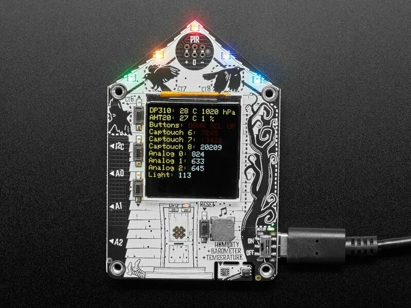
The code was submitted separately to Learn with the updated info.
I DM'd you the template editor link.
leaden walrus
cool. let me read those to get some context.
pallid grail
Sounds good
Here's another example with two things to update: https://github.com/adafruit/Adafruit_Learning_System_Guides/blob/main/CircuitPython_Templates/cap_touch_two_pad/code.py So you can see what it is like when it gets a little more complicated.
I ran that sketch, part of the last section is off the screen. I don't understand what's going on with the code well enough to figure out how to move it. Also the colors seem wrong... if I'm reading this correctly.
pallid grail
Ah
leaden walrus
here's an example for when things get really complicated:
https://github.com/adafruit/Adafruit_EPD/blob/master/examples/EPDTest/EPDTest.ino
pallid grail
uff.
Kind of figuring out how to tweak the position of the elements in the last part.
A lot of trial and error, and then waiting for compile and the whole program to run to get to the end 🙄
leaden walrus
and for that touch example - what if i have a hallowing?
pallid grail
um...
Yay! Fixed the button position.
Colors still seem wonky to me
Getting picture
leaden walrus
If using a HALLOWING M0, update TOUCH_PAD_PIN to TOUCH1, and TOUCH_PAD_PIN_TWO to TOUCH2.
pallid grail
Oh...
I thought you meant the .ino
I don't explain all possible options
I explain 2 as an example.
Same with all the others.
leaden walrus
just another example of how it gets tough to make a universal example, that is also easy to read

 leaden walrus
could be something else from copy pasta
pallid grail
How?
void mediabuttons() {
  // play
  tft.fillScreen(ST77XX_BLACK);
  tft.fillRoundRect(25, 5, 78, 60, 8, ST77XX_WHITE);
  tft.fillTriangle(42, 12, 42, 60, 90, 40, ST77XX_RED);
  delay(500);
  // pause
  tft.fillRoundRect(25, 70, 78, 60, 8, ST77XX_WHITE);
  tft.fillRoundRect(39, 78, 20, 45, 5, ST77XX_GREEN);
  tft.fillRoundRect(69, 78, 20, 45, 5, ST77XX_GREEN);
  delay(500);
  // play color
  tft.fillTriangle(42, 12, 42, 60, 90, 40, ST77XX_BLUE);
  delay(50);
  // pause color
  tft.fillRoundRect(39, 78, 20, 45, 5, ST77XX_RED);
  tft.fillRoundRect(69, 78, 20, 45, 5, ST77XX_RED);
  // play color
  tft.fillTriangle(42, 12, 42, 60, 90, 40, ST77XX_GREEN);
}```That seems pretty clear to me color-wise anyway....
And the red and green work in that first bit.
i.e. show up red and green.
Note in the image, my fancy now-entirely-on-the-display-buttons... 😄
leaden walrus
yah! pr it
pallid grail
Oh, heh. Yeah that would be an idea, wouldn't it.
leaden walrus
so i'm still thinking a separate example for each.
mainly due to the power feature on the feather
pallid grail
hmm.
leaden walrus
otherwise it would be much more template-able
import lib. create instance with pins. call init with size.
pallid grail
hmm ya.
leaden walrus
and we could add #defs for width/height for built in display boards
pallid grail
oh at the beginning that get pulled in later?
leaden walrus
then you could tft.init(TFT_WIDTH, TFT_HEIGHT);
pallid grail
ya ok
leaden walrus
same code line for all
pallid grail
I like it.
pallid grail
Right, but I don't plan to use this example directly in the lib. I intend to submit it to Learn.
owait
I don't follow.
OH
You mean actually define pins for the board in variants
I thought you meant in the example.
leaden walrus
yah. same as TFT_I2C_POWER etc
pallid grail
Ok ok, I follow now
leaden walrus
if in the example, it gets back to comment/uncomment mess
pallid grail
Right. I mean, fact is, we have a lot of that in CP examples too. And in this case, everything not needed would be deleted before submission to Learn.
I'll see how bad it is trying to template the code before committing to dedicated examples.
No idea how long it would take to get new #defs merged in the ESP32 Arduino core. I don't know how responsive they are to PRs, even if they're tiny.
leaden walrus
and there's also no standard naming for these. so yet another difference:
https://github.com/adafruit/Adafruit_nRF52_Arduino/blob/10ed826056f9c0b3079129a3ec37c3a90ecb0585/variants/clue_nrf52840/variant.h#L148
pallid grail
Thank you, I was looking for that just now
leaden walrus
different core, since nrf for clue
pallid grail
I figured that would be the case
Ya
I was looking for the core
Google was failing me so far.
leaden walrus
those CP example are being collected in learn repo
in CircuitPython_Temaples
thinking of setting up similar for arduino?
or OK to just link to examples living in library repos?
pallid grail
Yeah, I'm thinking Learn. I guess I hadn't thought it out fully, and probably was thinking it gets added to the CP_Templates folder 🙄
I mean... it's ok to do lib ones, but if I'm making them boilerplate with things to be updated, probably don't want it in a lib.
Because it will be, in theory, a non-functional example as-is.
Can you do #defines in an example? Like variables in Python?
Eh, probably no point.
Uff, TFT_BACKLITE vs TFT_BACKLIGHT. WHY... lol.
leaden walrus
you can - it works more like a text search/replace, before compile
pallid grail
Ah
leaden walrus
xkcd_new_standard.jpg
pallid grail
😄 Yeah
leaden walrus
so that dotstar example is sort of intentionally broken?
pallid grail
Yeah, it's designed to be updated.
leaden walrus
board.TOUCH_PAD_PIN_ONE
pallid grail
Not run as is.
pallid grail
Exactly.
Requires updating to work on anything.
It's a method I came up with for template code. Working out so far, at least for me and for Anne.
leaden walrus
how long have those been published?
pallid grail
To the Learn repo? umm... I'd have to check. I don't remember when we started templating.
leaden walrus
"working" as in people are finding that approach understandable?
pallid grail
Yeah. Only people creating templates end up utilising that code.
leaden walrus
or just copy/pasting non-working code directly and then wondering what's up?
pallid grail
10 months ago for the cap touch.
Unless someone is going through the Learn repo to find code, users never see that code.
Only template page creators.
leaden walrus
oh. yah. cause you change it.
pallid grail
11 months ago for Digital Input. So... somewhere around a year ago is when I started posting code like that.
Exactly.
It's linked in the template areas where it's meant to be embedded, but it gets changed and submitted to Learn in a "Adafruit_Board_Name" folder before getting embedded in a guide.