#help-with-arduino
1 messages · Page 102 of 1
 north stream
Yeah, ribbon cable with rectangular connectors, DIP headers, etc., as well as considering making custom PCBs
Yes, there's a matching shiftIn() for the other direction https://www.arduino.cc/reference/en/language/functions/advanced-io/shiftin/
The Arduino programming language Reference, organized into Functions, Variable and Constant, and Structure keywords.
 hollow imp
north stream
Yes, there's a matching `shiftIn()` for the other direction https://www.arduino....
hollow imp
north stream
Yes, there's a matching `shiftIn()` for the other direction https://www.arduino....
Thank you, I had found. So, I did my wiring and my first code, the LEDs light up but strangely :```
int latchPin = 9;
int clockPin = 11;
int dataPin = 5;
int rst = 7;
byte leds = 0;
void setup()
{
//Serial.begin(9600);
pinMode(latchPin, OUTPUT);
pinMode(dataPin, OUTPUT);
pinMode(clockPin, OUTPUT);
pinMode(rst, OUTPUT);
digitalWrite(rst, LOW);
}
void loop()
{
leds = 0;
updateShiftRegister();
delay(1000);
for (int i = 0; i < 8; i++)
{
bitSet(leds,0);
updateShiftRegister();
delay(100);
}
}
void updateShiftRegister()
{
digitalWrite(latchPin, LOW);
shiftOut(dataPin, clockPin, LSBFIRST, leds);
digitalWrite(latchPin, HIGH);
}```
north stream
What did you expect them to do? What did they actually do?
hollow imp
north stream
What did you expect them to do? What did they actually do?
I would like to light led by led, I have a photo of the PCB if you would like
 spiral flicker
If you’re just trying to turn on each LED one at a time, why not use bit shifting instead?
hollow imp
I tried in the other direction, to read the buttons, I manage to have data for the first 7 buttons
from 1 to 7 in order (252, 250,246, 238,222,190,126) and without support I have 254
hollow imp
spiral flicker
If you’re just trying to turn on each LED one at a time, why not use bit shiftin...
I do not know at all
spiral flicker
What is the purpose of this code? What is it supposed to do?
hollow imp
spiral flicker
What is the purpose of this code? What is it supposed to do?
I want to read the buttons and light the leds individually
spiral flicker
So for example when button one is pressed LED one turns on?
hollow imp
When I press a button I receive the information, and when I can turn on the led of my choice
I only have the connector sent previously and a photo of the PCB (There is not a lot of component on it)
 honest surge
could anyone help me get a pi pico to work with arduino ide on fedora
the tools > port option is greyed out
my user is part of dialout group
 waxen hawk
Hi, I am considering to buy arduino meg 2560 rev 3 as an upgrade from my uno. But i see two different types of products: elegoo and the original arduino amega. Has anybody tried elegoo products? Are they reliable compared to the original?
 native dagger
I've used elegoo before, I can't say that they are any worse than official fare, but I also can't see they are any better
native dagger
waxen hawk
Hi, I am considering to buy arduino meg 2560 rev 3 as an upgrade from my uno. Bu...
I think they are relatively reputable as far as I can tell.
waxen hawk
native dagger
I've used elegoo before, I can't say that they are any worse than official fare,...
Yeah elegoo products are super cheap and very enticing. yet I don't like the fact they copy the original's likenee hence some hesitancy. Have you come across any failures and are the specs exactly the same?
native dagger
I don't know about the specs, I suspect they are, but you can check. I haven't seen any failures but I've never used one to it's full capacity.
As for price, perhaps arduino charges more because they're the official supplier
waxen hawk
Thanks! Really appreciate hearing from a real user.
native dagger
Np!
honest surge
anyone?
waxen hawk
morning yall. Was wondering if anybody could help out where to find ac/dc powersupply? I am trying to power 16 channel relay module rack and each module gonna power a 5 v 0.25 a solenoid. Any recommendations?
north stream
This is one option. https://www.adafruit.com/product/658

This is a beefy switching supply, for when you need a lot of power! It can supply 5V DC up to 10 Amps, running from 110V or 220V power (the plug it comes with is for US/Canada/Japan but you ...
waxen hawk
north stream
This is one option. https://www.adafruit.com/product/658
Great, i'm a bitnew to relays but I was wondering if I would add more solenoids would i need more amperage?
north stream
Yeah, I figure 16 solenoids times 0.25A per solenoid works out to 4A, so you have some room to grow. I suggest using separate supplies for logic and solenoids.
waxen hawk
Nice, 10/0.25A = 40 solenoids! haha nice.
Can I cut the rubber of the powersupply to separate the wires?
 bleak socket
Hey guys, quick question
Does a CNC shield for Arduino NEED a jumper on the pin mode?
The M0 M1 or M2
 cedar mountain
bleak socket
Hey guys, quick question
Does a CNC shield for Arduino NEED a jumper on the pin...
cedar mountain
bleak socket
Hey guys, quick question
Does a CNC shield for Arduino NEED a jumper on the pin...
It's meaningful whether there are jumpers there or not, since the group of pins selects the motor-stepping option.
 elfin gazelle
What is wrong with this if code? Without the && x1 and y1 are working... if (x1.rose() && y1.rose())
 solemn cliff
can you give some context ? show more code ? is it polling too fast for them to be "risen" in the same loop ?
solemn cliff
elfin gazelle
What is wrong with this if code? Without the && x1 and y1 are working... if (x1....
but I can only speculate, it will depend on what you are trying to do and what else you are doing
elfin gazelle
Basically I want to have a matrix with Buttons on the X line and Button on the Y line. When I press x1 and y1 for example a LED should light up when both buttons are pressed. when those buttons are pressed again the LED should turn of. That wold be the full If thing:
if (x1.fell() && y1.fell()){
x1y1 = !x1y1;
Serial.println(x1y1);
}
but can it be that with the bounce library the buttons have to be pressed simultaneously?
solemn cliff
I'm not sure if fell() is only true once (the same loop where update() is called the first time after the button is pressed) or if it's sticky, but it's at least cleared after polling for fell() I believe
elfin gazelle
the problem with that way here is that it will update the statex1y1 all the time when both buttons are pressed.
int x1Value = x1.read();
int y1Value = y1.read();
if (x1Value == LOW && y1Value == LOW){
statex1y1 = 1
x1y1 = !x1y1;
Serial.println(x1y1);
}
I mean it udates x1y1 from 0 to 1 and back all the time
solemn cliff
yeah you would have to debounce the double state yourself
maybe you could try this, it would trigger when the second button is detected pressed while the first one is still pressed ?
if (x1.fell() && y1Value == LOW || x1Value == LOW && y1.fell() ){
  x1y1 = !x1y1;
  Serial.println(x1y1);
}
How can I write the code in that square here?
solemn cliff
ah here is a post with a guide:
#welcome message
elfin gazelle
`int x1Value = x1.read();
int y1Value = y1.read();
if (x1Value == LOW && y1Value == LOW){
statex1y1 = 1
x1y1 = !x1y1;
Serial.println(x1y1);
}`
this seems to work as well. but yours looks more elegant. will check it out
solemn cliff
```arduino works for arduino code
I think if you don't want to continuously trigger for the length of the buttons being down with your code, you would need to add some if(!statex1y1) and some if (x1Value == HIGH || y1Value == HIGH) statex1y1 = 0;, the whole state variable dance of edge detection
elfin gazelle
cool, another questions. I would like to achieve something like this. This function is obviously not working but is there a way t work with an input in a function like this? So that in this example, it prints the x according to the value I give it to the function? `void matrix(int xnum) {
int x1 = 1;
int x2 = 2;
int x3 = 3;
Serial.println(x+xnum)
}`
cedar mountain
elfin gazelle
cool, another questions. I would like to achieve something like this. This funct...
You're probably looking for array indexing:c void matrix(int xnum) { int x[] = {1, 2, 3}; Serial.println(x[xnum-1]); // start from 0 }Note that this is horribly unsafe if xnum is not in the correct range, so some if-then checks for that is recommended unless you really trust the code calling the function.
 pine bramble
Don't know if right channel, but how can I plug things in parallel on the -/+ row of a breadboard or it's not possible in the context of an arduino ? Would it even make sense to connect power in and ground in parallel ?
And how can I tell if it's the lines that are in series or the rows on a random breadboard I get without removing the sticker behind it ? Are there markings ? (If I ask it's because I,ve gotten some before not done in the normal way)
native dagger
Can you use fritzing to post what you're planning?
pine bramble
Just a theorical question, all breadboard have seen only have 1 column for + and 1 column for -
native dagger
interesting, I've had the opposite experience
pine bramble
I mean I know there is a left one and right one but they are a bit far
I meant like 2-3 columns on the left for each
native dagger
I have connected ground on one side to ground on another before. Same for power
 pine bramble
and accessories I guess
seems to come with probe points, jumper wires and tie-point blocks
 brazen falcon
One thing you have to keep an eye out on unknown breadboards is that the power and ground rails are sometimes split in half on full-length boards. USUALLY those ones have a split in the red/blue line to indicate that but not always.

I really dislike this type
 mortal seal
In trying to use the stemma connection on the pico feather with the seesaw rotary encoder but it doesn’t see the seesaw. It works with circuit python but not for me with arduino. (Just using the default example). Could it be the default Wire pins?
north stream
brazen falcon
I really dislike this type
You can sometimes modify them by soldering a wire across the gap (how to do this depends on the construction of your breadboard and how tolerant you are to melted plastic. Some of them, you can peel the backing away at the edges, remove the metal contacts, solder a wire to them, put them back, and stick the backing back in place)
brazen falcon
Or just bin it and get a proper one.
 zealous comet
can somebody help me out with this please?
Pastebin
Pastebin.com is the number one paste tool since 2002. Pastebin is a website where you can store text online for a set period of time.
getting a expected primary-expression before '}' error
zealous comet
#include <Adafruit_NeoPixel.h>
#ifdef AVR
#include <avr/power.h>
#endif
// Define display parameters
#define PIN 6
#define NUMPIXELS 7
#define DELAYVAL 500 // Time (in milliseconds) to pause between pixels
// Define uS module pins
#define TRIG_PIN 9
#define ECHO_PIN 10
Adafruit_NeoPixel display(NUMPIXELS, PIN, NEO_GRB + NEO_KHZ800);
void setup() {
display.begin();
pinMode(TRIG_PIN, OUTPUT); // Sets the trigPin as an Output
pinMode(ECHO_PIN, INPUT); // Sets the echoPin as an Input
Serial.begin(9600); // Starts the serial communication
}
void loop() {
// Clears the trigPin
digitalWrite(TRIG_PIN, LOW);
delayMicroseconds(2);
// Sets the trigPin on HIGH state for 10 micro seconds
digitalWrite(TRIG_PIN, HIGH);
delayMicroseconds(10);
digitalWrite(TRIG_PIN, LOW);
// Reads the echoPin, returns the sound wave travel time in microseconds
long duration = pulseIn(ECHO_PIN, HIGH);
// Calculating the distance
int distance = duration * 0.034 / 2;
// Prints the distance on the Serial Monitor
Serial.print("Distance: ");
Serial.println(distance);
display.clear();
display.setBrightness(10);
if (distance < 10) {
for (int i = 0; i < NUMPIXELS; i++) {
display.setPixelColor(i, display.Color(255, 0, 0));
}
} else if (distance < 20) {
for (int i = 0; i < NUMPIXELS; i++) {
display.setPixelColor(i, display.Color(0, 0, 255));
}
} else {
for (int i = 0; i < NUMPIXELS; i++) {
display.setPixelColor(i, display.Color(255, 255, 0));
}
}
display.show();
}
fixed my code so far, but I'm still only getting 2 colors instead of 3 for some reason
 cold lagoon
I've made an PCB with an NRF24l01 (and some other stuff). But the NRF24l01 doesn't really work. I've tested the code with an Arduino nano connecting to an Arduino UNO and that worked but Arduino Leonardo (Atmega32u4) to Arduino UNO doesn't work for some reason. here is the wiering:
 mortal seal
 leaden walrus
<@!770484464232693770> stemma on feather rp2040 is `Wire1`
leaden walrus
<@!770484464232693770> stemma on feather rp2040 is `Wire1`
Thank you. That makes sense. I tried initializing the seesaw with
ss(&Wire1) - still no luck. Is this the way to switch the SDA device?
 vivid rock
zealous comet
fixed my code so far, but I'm still only getting 2 colors instead of 3 for some ...
vivid rock
zealous comet
fixed my code so far, but I'm still only getting 2 colors instead of 3 for some ...
does it read distances correctly?
zealous comet
Yes, it does @vivid rock
Btw, I fixed my code
#include <Adafruit_NeoPixel.h>
#ifdef AVR
#include <avr/power.h>
#endif
// Define display parameters
#define PIN 6
#define NUMPIXELS 7
#define DELAYVAL 500 // Time (in milliseconds) to pause between pixels
// Define uS module pins
#define TRIG_PIN 9
#define ECHO_PIN 10
Adafruit_NeoPixel display(NUMPIXELS, PIN, NEO_GRB + NEO_KHZ800);
void setup() {
display.begin();
pinMode(TRIG_PIN, OUTPUT); // Sets the trigPin as an Output
pinMode(ECHO_PIN, INPUT); // Sets the echoPin as an Input
Serial.begin(9600); // Starts the serial communication
}
void loop() {
// Clears the trigPin
digitalWrite(TRIG_PIN, LOW);
delayMicroseconds(2);
// Sets the trigPin on HIGH state for 10 micro seconds
digitalWrite(TRIG_PIN, HIGH);
delayMicroseconds(10);
digitalWrite(TRIG_PIN, LOW);
// Reads the echoPin, returns the sound wave travel time in microseconds
long duration = pulseIn(ECHO_PIN, HIGH);
// Calculating the distance
int distance = duration * 0.034 / 2;
// Prints the distance on the Serial Monitor
// Serial.print("Distance: ");
// Serial.println(distance);
display.clear();
display.setBrightness(10);
if (distance < 10) {
Serial.println("Less than 10");
for (int i = 0; i < NUMPIXELS; i++) {
display.setPixelColor(i, display.Color(255, 0, 0));
}
} else if (distance < 20) {
Serial.println("More than 10, less than 20");
for (int i = 0; i < NUMPIXELS; i++) {
display.setPixelColor(i, display.Color(0, 0, 255));
}
} else {
Serial.println("More than 20");
for (int i = 0; i < NUMPIXELS; i++) {
display.setPixelColor(i, display.Color(255, 255, 0));
}
}
display.show();
delay(1000);
}
For some reason changing the print statements fixed it
 stuck coral
zealous comet
For some reason changing the print statements fixed it
stuck coral
zealous comet
For some reason changing the print statements fixed it
Going to guess it was the delay more than anything

Feel free to use the discord code formatting with three `s to make it easier for people reading
 stoic scroll
Anyone knows how to read and write to the flash memory using LittleFS? The example is not explaining how to write block device operations. https://github.com/adafruit/Adafruit_nRF52_Arduino/tree/master/libraries/Adafruit_LittleFS/src/littlefs
GitHub
Adafruit code for the Nordic nRF52 BLE SoC on Arduino - Adafruit_nRF52_Arduino/libraries/Adafruit_LittleFS/src/littlefs at master · adafruit/Adafruit_nRF52_Arduino
 rich coral
is Arduino IDE 2.0 usable at this point ?
 supple turret
Not tried it yet..
leaden walrus
mortal seal
Thank you. That makes sense. I tried initializing the seesaw with
ss(&Wire1) - ...
see if the address will show up in an i2c scan:
https://learn.adafruit.com/scanning-i2c-addresses/arduino
if not, then there is some basic connection or other issue. if address shows up, then it's something else, would need more info on how things are connected.
pine bramble
I’m really curious if someone can tell me, having played with python recently. Is it that advantageous with esp32-s2 chipsets to use arduino or python? I’m reasonably familiar with both I’d guess. For whatever that’s worth.
 livid osprey
pine bramble
I’m really curious if someone can tell me, having played with python recently. I...
livid osprey
pine bramble
I’m really curious if someone can tell me, having played with python recently. I...
Arduino has access to lower-level functions and methods, while Python has less time spent writing extra lines of code and waiting for it to compile. Both options have their own advantages, and it really comes down to application needs and developer preference.
pine bramble
livid osprey
Arduino has access to lower-level functions and methods, while Python has less t...
Sounds like a reasonable case to not spend quite as much time forgetting the syntax of arduino and keep with that. I really struggled during this last project with python purely from a standpoint of it feeling chaotic.
solemn cliff
with web APIs that require json or string manipulations, I feel more comfortable to work with python, but I tend to default to python in general unless I have specific needs that are better addressed in C
pine bramble
solemn cliff
with web APIs that require json or string manipulations, I feel more comfortable...
See now that’s a game changer as I want to work with webstuff. Maybe it’s good to understand both
I’m a wishy washy sorta fella
pine bramble
Is there really any point in completing basic tutorials if I had taken random chips/sensors before and wired them correctly (after a last revision from you guys), I feel like I just need the datasheet to know how to wire it/what code to write ?
Or I might miss some basic things having skipped tutorials ?
pine bramble
ok 😦
 tidal vale
Greetings! I'm trying to use the Adafruit seesawPreipheral in one of my projects, but the ATtiny8x7 are very out of stock, but I was able to get (and have a few) ATtiny1614 devices so I wanted to add support to the library for them. However, I'm having difficulty understanding what the ALL_GPIO, ALL_ADC, and ALL_PWM defines (which are chip specific) are trying to do. Referencing them to the data sheets isn't making sense to me. I wasn't sure if the best place to ask questions was here or in a GitHub issue, I'd be happy to add the appropriate defines for all the common chips available via drazzy's (maintainer of tinyAVR) as part of my PR for the library if that would be acceptable. What's the best way to proceed?
pine bramble
what confuse you exactly in https://github.com/adafruit/Adafruit_seesawPeripheral/blob/main/Adafruit_seesawPeripheral.h ?

GitHub
Arduino library for making seesaw peripherals using Arduino core! - Adafruit_seesawPeripheral/Adafruit_seesawPeripheral.h at main · adafruit/Adafruit_seesawPeripheral
the bit mask ?
tidal vale
Yeah, I can't figure out the relation between the bitmask and the ports/pins
pine bramble
0x1FFFFFUL // this is chip dependant, for 817 we have 21 GPIO avail (0~20 inc) just mean 21 bits unsigned long bitmask ie: 21x1
since the family of chips have at most 21 pins, need a bitmask with 21 1
tidal vale
That I get, but the PWM and ADC mask doesn't line up with what the datasheets report
I think it's trying to capture this information from the ATtiny417/814/816/817 datasheet but I don't understand how
 pine bramble
yeah I see the confusion 😦
tidal vale
The good news is that "cheating" and bringing those defines from the 817 over and compiling for a 1614 works, and will even fit on the device! Now I just need to figure out the right values so it has a chance of working...
livid osprey
tidal vale
Yeah, I can't figure out the relation between the bitmask and the ports/pins
https://learn.adafruit.com/assets/105461 The seesaw breakout schematic is very helpful in mapping the pins to their corresponding GPIO definitions.
pine bramble
yeah but the datasheet doesn't even match the code to start with
the 1617 have either 20 or 24 pins not 21, and at most 2-3 pins without analog....
tidal vale
Yes, the schematic does help for figuring out pin to port mapping, but not the pin to PWM/ADC mapping
pine bramble
the pdf isn't even searchable...
livid osprey
Each bit corresponds to the GPIO number aka the wire number in the schematic, starting with 0 on the far right (LSB)
For ADC, all the AIN-labeled pins in the schematic match up to a 1 bit, while the remaining pins are all 0.

TXD, RXD, SCL and SDA are also GPIO 8-11, and are included in the ALL_GPIO/ADC/PWM bits, but are noted in the INVALID_GPIO define as well, to filter them out of the VALID_GPIO bitmask later on.
tidal vale
Ah, OK - so it matches this pinout but not the function table

So the ADC bitmap makes sense now, just need to decode the PWM map
Thanks for the pointers @pine bramble and @livid osprey !
livid osprey
Looks like the PWM is whatever TCA and TCD are mapped to. The PWM functionality is probably dependent on the timers with the particular controls those two timers have.
pine bramble
tangent question @livid osprey seems you are experience, why so much pages for a datasheet?
livid osprey
An MCU has a lot more detail than its dev board lets on. Things like architecture, instruction sets, peripheral multiplexing, etc, are all critical development details that are handled for you by the circuitpython packages and arduino builds you can download off the internet haha
All those details, the hobbyist tinkerer doesn't need to know about to get things to work, but someone has to engineer the dev board and packages with those very details to get to that point.
pine bramble
Can I assume those are "correct" just like the datasheet "are" ?
ie: can't do anything with my current knowledge anyway if they aren't
I mean I don't see how different that is from using windows.h and directX library hoping that the video cards drivers and windows API methods are correct...
livid osprey
Yes? As long as you're working with manufactured boards and not raw chips/PCB design, you shouldn't really need to worry about the details in the datasheet.
 rose moss
has anyone ever ran Arduino in their car for lighting control?
pine bramble
anyone=yes, in here I don't know, know a guy at work who has some sensors on his car and can check from from at work. also if you interfere too much with the car the car could lose road legal classification
north stream
Heh, yeah
pine bramble
might want to start with a post like this: https://arduino.stackexchange.com/questions/4179/using-arduino-to-control-a-12v-car-light-system

Arduino Stack Exchange
I am new, but I am wondering what options I may have to control a 12v line that connects to a light with Arduino i/o.
Given the voltage limitations of an arduino, I am thinking using some kind of 5v

Instructables
Arduino RGB Interior Car Lighting (Bluetooth - Android App): In this Instructables guide I will show you how to make an RGB interior car lighting by using the Arduino uno board (or any other Arduino based board).I made my own circuit by using the ATmega328 micro controller but this is an optional step. In thi…
pine bramble
north stream
Heh, yeah
in my state using a carrousel led system made the car not street legal (too distractive to other drivers))
north stream
The rotating and flashing lights on top make that one a little distracting as well.
pine bramble
to control say headlights with it you'll need some tricks because arduino don't have enough voltage and these are grounded to the car battery usually
north stream
For heavy loads like that, I like big transistors, or relays like https://www.goldmine-elec-products.com/prodinfo.asp?number=G25771 (and driver circuitry to control the relays)

Standard plug-in auto relay operates on 12VDC and features SPDT contacts rated 30/40Amp. Has 5 terminals on bottom. Part# CDR851CUESN-24D. Size 1.1" x 1.2" x 0.97" tall (excluding terminals). New!
pine bramble
Just gotta be careful because some amps are involved specially from the lead battery
And you have to be careful especiall;y if you want to run an arduino from it as well with rectifiers/diodes etc
Just because something runs on 12V/5A doesn't mean you can't use 5V/30mA logic to tell it what to run and when 😄
north stream
Yes, vehicles are subject to an effect known as "load dump", which can throw a couple hundred volts on a nominally 12V supply (which often runs over 14V when the engine is running).
The sign scrollers pictured run from ordinary UBECs which have been in place for about three years now and still work fine.
pine bramble
north stream
Yes, vehicles are subject to an effect known as "load dump", which can throw a c...
even if something was 24V if it's digital can't I connect a 5V arduino on it and send it voltage above the 24V digital range for a value of 1 ?
Like says their range is above 3V is 1?
This is an example: https://www.carlingtech.com/controls-cltm12s-series let you install custom controls on a car/ship/rv dashboard etc, uses tons of volts and amperes in a range
The CLTM12-S is a compact load controller. This electronic control module offers a selectable baud rate and real-time fault monitoring for all 12 outputs.
BUT "The digital inputs (IND_1, IND_2, IND_3. IND_4_WKE) sense the presence of three voltage level states: “Active High”, “Open” and “Active Low” and are compatible with standard 5v logic devices"
So technically these devices seems you could control the controller with an arduino while it's connected to regular car healights, honk etc
north stream
Yes, many devices include interfaces or level converters to allow them to safely communicate with low voltage electronics.
vivid rock
north stream
Yes, vehicles are subject to an effect known as "load dump", which can throw a c...
couple hundred volts??
how do you protect from that? this would fry any electronics I can think of
north stream
Transient voltage suppressors, zener diodes, filter and decoupling networks, etc. There are even special protective chips made for just such environments.
pine bramble
you can also buy usb converter which is a relatively standard car part
north stream
Automotive electronics is some of the most robust stuff out there. Subjected to blistering heat, freezing cold, all kinds of humidity, vibration, no maintenance for decades, horrible power, etc.
pine bramble
that will provide 5V@3A off the battery for your arduino
And no need to check the 3A, that is a maximum, arduino will draw what it need up to its specs of 150mA
 uncut kindle
I'm coming back with the same problem I had before, but with a bit more insight
I'm having trouble uploading code to my Adafruit Feather M4 Express via the Arduino IDE
I have downloaded the proper board library and I'm trying to upload just a mostly blank file to make sure I can get it consistently
I have my board hooked up to my computer via USB to Micro USB and the board is connected to nothing else, although it has pins soldered on.
I double click the reset button to put the chip in bootloader mode, then I select the board port PORT4 in the Tools tab of the IDE

Then I'll just click Upload
Very occasionally this'll work, but most of the time my result is something like this:
Arduino: 1.8.16 (Windows 10), Board: "Adafruit Feather M4 Express (SAMD51), Enabled, 120 MHz (standard), Fast (-O2), 50 MHz (standard), Arduino, Off"

Sketch uses 12504 bytes (2%) of program storage space. Maximum is 507904 bytes.

Device       : ATSAMD51x19

Version      : v1.1 [Arduino:XYZ] May 17 2020 17:56:23

Address      : 0x0

Pages        : 1024

Page Size    : 512 bytes

Total Size   : 512KB

Planes       : 1

Lock Regions : 32

Locked       : none

Security     : false

BOD          : false

BOR          : true

Write 12760 bytes to flash (25 pages)

[==============================] 100% (25/25 pages)

Done in 0.203 seconds

Verify 12760 bytes of flash

[========                      ] 28% (7/25 pages)

SAM-BA operation failed

An error occurred while uploading the sketch


This report would have more information with
"Show verbose output during compilation"
option enabled in File -> Preferences.
SAM-BA operation failed
The same error occurs when the chip is unplugged during the file verification, so at a guess the chip is somehow disconnecting itself during the upload
I've done my research to find people with the same error but their answers are about as consistent as my results. I found one that said they just plugged a different mouse into their computer and the error fixed itself'
Anyone have any idea what I could do to fix this?
 compact pine
Dumb Arduino question, but in this code block:
/* Assign a unique ID to this sensor at the same time */
Adafruit_HMC5883_Unified mag1 = Adafruit_HMC5883_Unified(1);
Adafruit_HMC5883_Unified mag2 = Adafruit_HMC5883_Unified(2);
Why is it necessary to do a variable assignment after? Isn't it sufficient to write Adafruit_HMC5883_Unified mag1 for object instantiation to a unique variable name?
uncut kindle
Oh also idk if it's relevant but it always gets stuck at the same page when it does get stuck
uncut kindle

Adafruit Learning System
Get running faster than ever with the first Adafruit Express board
I just found this guide on transferring code via the bootloader mode of the Feather M4 but it says that I need to transfer the files in .uf2 format, and provides a Python script for converting a .bin file into .uf2. Would this work with the build from any .c or .cpp compiler?
 brave roost
I'm inputting 1.06 volts thru my bench power supply (non-transformer type), teensy reads it as 1.61 volts
did I break it?
I previously had a piezo crystal plugged into a different analog in, though it was never struck 'that hard', some tapping with the finger
north stream
compact pine
Dumb Arduino question, but in this code block:
```
/* Assign a unique ID to this...
Adafruit_HMC5883_Unified mag1 merely creates a variable of a particular type. Adafruit_HMC5883_Unified(1) creates an instance of an object. Then = assigns that object handle to that variable.
brave roost
is such deviation between input and what it reads normal maybe? I verified it with my multimeter, it is indeed 1.06 going in
livid osprey
Do you have separate grounds or a different reference voltage, perhaps?
brave roost
as in test with different ground pins? I tried from 2.5 to 0.4 volts
the relative range is on point, no dead spots or anything like that
but say when my psu reads 0.4 the serial monitor reads 1.0
livid osprey
Your teensy is probably interpreting your voltage input as a 0-5V signal, but you have a 3.3v reference instead of 5.
brave roost
Ah, yes
I did tell it to interpret it as 5
so the error was that the ceiling is 3.3
and thus it interprets it wrong
yes?
livid osprey
Yes
livid osprey
If you multiply your 1.06 by 5/3.3, you get 1.606v
livid osprey
No, no problem at all! Don’t worry about it, if only all the problems had simple solutions like this haha
brave roost
speaking of problems with less simple solutions,
that piezo I was reading thru analog in was giving me a hard time, if I tap it with the finger it reads things reasonably nicely, however if I tape it to my desk and tap the desk or even bang on the desk there's no output
I tried running it just gnd / A01 and that was how it behaved
and then I tried it with a LM258 (op-amp, maybe wrong type?) to get just about identical results
I've seen people on the net tape those to guitars n such and get good output, so I am puzzled as to what I am doing wrong
if you have any advice in which direction I should go or any article I could read to get a better understanding of this?
 slate pendant
hey guys I'm trying to use a pointer to point to the TCNT1 (I'm using TCNT1A and B) register and two variables to create a 32bit (unsigned long) counter through software but the compiler and IDE2.0 just gives me this.
I've also tried the pointer tutorial from reference which has the same effect.
Solution to create 32bits from 4 bytes found here:
https://forum.arduino.cc/t/how-to-combine-four-8-bit-int-numbers-to-create-a-32-bit-number/287382/2
Please @ me if you have literally any idea what wrong with my code :)

Arduino Forum
Suppose you have 4 bytes (= 8-bit numbers, or uint8_t), called b1…b4, b1 being they the LSB and b4 the MSB. To turn them into a long do this: uint32_t myLongNum = (b4 << 24) | (b3 << 16) | ( b2 << 8 ) | (b1); uint32_t is a native unsigned, 32-bit integer, it is an unsigned long. (Note: you can also try using “+” instead of “|” in the code abo...
 stable forge
@uncut kindle Try another USB cable that you are sure is working as a data cable. We see more trouble with USB cables than anything else. Also try another USB port, and if you are using a USB hub, try connecting directly. Reboot the host computer as well.
Your technique of double-clicking and then selecting the port is exactly what I would suggest.
You can also try the cleanup tool described here: https://learn.adafruit.com/welcome-to-circuitpython?view=all#device-errors-or-problems-on-windows-3094694-11
slate pendant
stable forge
<@!283408510492868608> Try another USB cable that you are sure is working as a d...
sry but are you answering the questions here in order?
stable forge
no, I am only answering ones I have immediate answers. I'm not being systematic. This is not an official support channel.
pine bramble
does it solve an actual problem or is that homework/theory ?
slate pendant
actual problem
stable forge
the pointer stuff is not right. Take away the & before the uint8_t's. Could you paste the code here instead of taking a picture?
it's hard to read
See the end of #welcome for how to paste code
slate pendant
volatile uint8_t TCNT1HL; // 24bit extension of Timer1
volatile uint8_t TCNT1HH; // 32bit extension of Timer1 TCNT1
volatile uint16_t *TCNT1F;
TCNT1F = ((TCNT1HH)<<8)|(TCNT1HL);
volatile uint32_t *TCNT1FF;
TCNT1FF = (TCNT1HH<<24)|(TCNT1HL<<16)|(TCNT1H<<8)|(
TCNT1L); // up to 268 seconds (4min)
why is TCNT1F a pointer?
solemn cliff
isn't the issue that your are doing assignments outside of a function or initialization ?
livid osprey
brave roost
that piezo I was reading thru analog in was giving me a hard time, if I tap it w...
Most likely not secured tightly enough for the vibrations to transfer properly. If it’s still in test, perhaps try putting some weight on it?
stable forge
I would just do:
volatile uint8_t TCNT1HL; // 24bit extension of Timer1
volatile uint8_t TCNT1HH; // 32bit extension of Timer1 TCNT1
volatile uint16_t TCNT1F;
TCNT1F = ((TCNT1HH)<<8)|(TCNT1HL);
volatile uint32_t TCNT1FF;
TCNT1FF = (TCNT1HH<<24)|(TCNT1HL<<16)|(TCNT1H<<8)|(
TCNT1L); // up to 268 seconds (4min)
are those hardware registers?
or just variables?
slate pendant
stable forge
why is TCNT1F a pointer?
TCNT1 is a 16 bit Counter/Timer hardware register, that I need to extend with regular variables to 32 bits.
This code is outside of any function because I need the pointers to be global and I cant afford wasting CPU cycles on constantly assigning the variables
stable forge
ok, looks like TCNT1 is a predefined variable somewhere
solemn cliff
solemn cliff
isn't the issue that your are doing assignments outside of a function or initial...
that's what the "TCNT1F does not name a type" error means, you are doing things outside of a function
slate pendant
stable forge
ok, looks like TCNT1 is a predefined variable somewhere
can find definition by going to definition of micros() function
stable forge
do not declare TCNT1, just assign to it:
TCNT1 = something
slate pendant
solemn cliff
that's what the "TCNT1F does not name a type" error means, you are doing things ...
how can I declare it globally inside a function tho
I thought defining a pointer was ok outside functions
solemn cliff
ok
int thing = 1;
not ok= error: 'thing' does not name a type
int thing;
thing = 1;
or you init it in setup()
slate pendant
solemn cliff
ok
```arduino
int thing = 1;
```
not ok= **error: 'thing' does not name a type**...
tried this already
stable forge
random code from a page:
void setup()
{
  pinMode(ledPin, OUTPUT);

  // initialize timer1
  noInterrupts();           // disable all interrupts
  TCCR1A = 0;
  TCCR1B = 0;

  TCNT1 = 34286;            // preload timer 65536-16MHz/256/2Hz
  TCCR1B |= (1 << CS12);    // 256 prescaler
  TIMSK1 |= (1 << TOIE1);   // enable timer overflow interrupt
  interrupts();             // enable all interrupts
}

ISR(TIMER1_OVF_vect)        // interrupt service routine that wraps a user defined function supplied by attachInterrupt
{
  TCNT1 = 34286;            // preload timer
if I init in setup can I use it in interrupts/other functions?
stable forge
TCNT1 is assigned to. It does not need to be declared: it is already declared implicitly by the Arduino magic
which adds includes, etc.
stable forge
I know, you don't need to. Why not just assign to it if you want to set its value
I'm not sure what you mean by "extensions"
slate pendant
TCNT1 is 16 bit
I need 32 bits of counter precision
so I take TCNT1L (lower part of TCNT1, predefined) and TCNT1H and more or less extends its memory space to 32 bits by assigning it to an unsigned long
stable forge
I'm trying to find the timer description in the datasheet
stable forge
ESP8266 will have completely different registers
slate pendant
yes I need the micro for debugging tho
stable forge
so ideally you would use a Timer library that is implemented on both
slate pendant
Timer libraries are not designed for <500ns operation also I need a counter library not Timer even tho hardware side its the same
 slate pendant
yes I need the micro for debugging tho
slate pendant
slate pendant
yes I need the micro for debugging tho
(my ESP8266 modules dont have enough pins for serial AND polling data pin)
stable forge
I don't see that the hardware provides 32 bits of timer precision anywhere
slate pendant
exactly thats why I need to implement it through software
stable forge
do you mean you are going to simulate it?
slate pendant
I can waste a couple singular cycles every 65535 cycles for incrementing another variable but I need to read out both at the same time as it were an unsigned long
stable forge
so you are going to simulate the upper 16 bits, and make the lower 16 bits be the actual TCNT1 register? The TCNT1 register is at a fixed place in the address space, so you can't store data adjacent to it.
slate pendant
stable forge
so you are going to simulate the upper 16 bits, and make the lower 16 bits be th...
YES
thats what I found through own research
it technically has 2 more bytes beneath it on the micro but thats not a good approach
stable forge
uint32_t TCNT1_32; // Fake TCNT1 register, extended to 32 bits
...
// Set the lower 16 bits of TCNT1_32 with the value from TCNT1
TCNT1_32 = (TCNT1_32 & 0xffff0000) | TCNT1;
you could use C unions or a struct also
slate pendant
stable forge
```c
uint32_t TCNT1_32; // Fake TCNT1 register, extended to 32 bits
...
// Set t...
this would require an assignment, which I'm trying to avoid in the interrupt
but it is what I'm trying to do with pointers
stable forge
I'm still confused by this. You could just store the upper 16 bits somewhere else and merge them when you want a full 32-bit value:
uint16_t FAKE_TCNT1_HIGH_16_BITS;
...
uint32_t FAKE_TCNT1_32;
FAKE_TCNT1_32 = (FAKE_TCNT1_HIGH_16_BITS << 16) | TCNT1;
ok hang on
pine bramble
pointer require an assignment of memory value to not point to null...
they are more costly than variables on the assignement cost
their point is access cost
stable forge
a pointer is an address. You have to dereference it
slate pendant
yes access cost is the problem
stable forge
what interrupt is the interrupt routine invoked on? TImer overflow?
slate pendant
I have the following two interrupts:
void IRQ() {
  #if defined(TCNT1FF)
      Time = TCNT1FF;
  #elif defined(TCNT1)
      Time = TCNT1;
    #warning TIMER 1 is only 16 bit
  #else
      #error TIMER 1 not defined
  #endif
  if ( digitalPinToPort(_PIN) ) {
    T0E, T1S = Time;
  } else {
    T1E, T0S = Time;

    // one full bit has been sent, now calculate if it was HIGh or low.

  }

}
an assignment is a cheap operation; i'm not sure why you're concerned about it
slate pendant
and
ISR(TIMER1_OVF_vect) { // triggers on Timer1 overflow
  *TCNT1F += 1; // increases upper 16 bits by 1 until overflow
}
so to fetch the entire 32-bit value, it's (TCNT1F << 16) | TCNT1
TCNT1F is your software-simulated top 16 bits, I think
slate pendant
stable forge
so to fetch the entire 32-bit value, it's `(TCNT1F << 16) | TCNT1`
is this possible in a pointer tho?
stable forge
a pointer to what?
why does TCNT1F need to be a pointer? Why can't it just be a static 16-bit variable?
slate pendant
stable forge
so to fetch the entire 32-bit value, it's `(TCNT1F << 16) | TCNT1`
wait I think I just noticed I can do THIS in a #define
slate pendant
stable forge
why does TCNT1F need to be a pointer? Why can't it just be a static 16-bit varia...
I wanted to have the 32 bits as its own variable name, consisting of The upper and the lower bits of software simulated and regular TCNT1
so I can access each on its own easily. but using a regular definition for this should work, let me try ( I just really didnt understand why my pointers didnt work )
stable forge
TCNT1 itself can't be in there, because it's not in RAM, it's a register. SO there is not RAM adjacent to it. So no matter what, you have to copy what's in TCNT1 to the lower part of your 32-bit value.
but you don't have to copy that until you need the value, somewhere outside of the irq routine(s)
slate pendant
it compiled
I'll see if it works - PS: I was the one ages ago who asked how to read Neopixel (i.e. WS2812B) data and transmit it over WiFi, guess what my problem was up until now :D
I've set TCNT1 up without a prescaler and now just need to properly call the interrupt from when it overflows but I think I already got it working if the documentation is right.
stable forge
you can use a union:
#include <stdint.h>
#include <stdio.h>

union {
    uint32_t full32;
        struct {
            uint16_t low16;
            uint16_t high16;
        };
} num;

int main() {
    num.low16 = 1;
    num.high16 = 2;
    printf("0x%x\n", num.full32);
}
prints 0x20001
slate pendant
I've really gotten deep into C/Arduino and even ASM coding to find out how to read a signal that alledgedly is wayy too quick for a 16MHz arduino because micro() only does 8micro second intervals but the controller can PRODUCE the signal anyway :D
slate pendant
stable forge
you can use a union:
```c
#include <stdint.h>
#include <stdio.h>
union {
ui...
thank you, I will look into that if I want to do it like I wanted again a couple minutes ago, now I've used the #define to insert (TCNT1F << 16) | TCNT1 everywhere I type TCNT1FF :D
you guys were a great help it is appreciated! if you have a coffe jar let me know I'll put some in when I finish my project!
brave roost
I'm trying to read my data with serial plotter, however after a few seconds of running my plotter stops updating
script looks as basic as it gets,
void setup(){
}
void loop() {
  test = analogRead(A1);
  Serial.println(test);
}
teensy 4.1, tested at 24mhz n 1ghz (yes its cooled)
stable forge
slate pendant
you guys were a great help it is appreciated! if you have a coffe jar let me kno...
glad you're on track. ... If you buy stuff from us, that's how we get money 🙂
slate pendant
is it also if I buy arduino boards from a closer retailer?
compact pine
north stream
`Adafruit_HMC5883_Unified mag1` merely creates a variable of a particular type. ...
Interesting. I'm a little confused as I've seen in other libraries SENSOR variablename work without needing the equals? Is that a subtle difference between just creating variable of a type versus a variable of a type that's a class instantiation?
north stream
Yes, it depends on how the library is implemented.
brave roost
livid osprey
Most likely not secured tightly enough for the vibrations to transfer properly. ...
tested with double sided tape on the table, nothing gets triggered when I smack my desk
north stream
brave roost
if you have any advice in which direction I should go or any article I could rea...
Those sensors mostly respond to bending/flexing. If they're taped to a solid item, they won't flex much and therefore won't produce a large signal. When used as microphones, a low output is sufficient, as microphones are plugged into amplification circuits. However, to get enough (unamplified) output to drive an Arduino input, you'll generally need more flexing/shear/compression.
leaden walrus
@brave roost serial plotter stopping - might be related to not calling Serial.begin() in setup()?
brave roost
north stream
Those sensors mostly respond to bending/flexing. If they're taped to a solid it...
I'm interested in capturing sound via arduino input through these, would you be able to point me to some kind of a valid amplification circuit I could use for this?
I tried an op-amp through someone else's recommendation, but I am not able to get it to do the things I want it seems
north stream
An op-amp is generally workable, but does require some circuit knowledge to get working properly. There are dedicated chips for it, like the one used in this breakout: https://www.adafruit.com/product/1063

Add an ear to your project with this well-designed electret microphone amplifier. This fully assembled and tested board comes with a 20-20KHz electret microphone soldered on. For the ...
brave roost
mine is a contact piezo crystal not an air suspended one
I was considering to grab one of those mic modules and swap out the crystal bit
though wasn't sure if that was the best way to go about it
north stream
I don't know if it's the best way either, but probably worth a try.
brave roost
I have enough knowledge to assemble a circuit, but rather not have to hunt down that one odd-ball piece for months
north stream
You're probably better off with an ordinary transistor or op-amp amplifier.
 loud light
I need a hand getting the Adafruit_ST7789 2" TFT working with the FeatherS2. Using the adafruit gfx lib, I can only seem to initialize the screen using the software SPI method. I'm having trouble getting the feather's hardware SPI to work. I suspect it's related to the board also using SPI internally for the SD card. Does anyone have experience getting the graphicstest.ino sample to work with a FeatherS2 & ST7789? I'm guessing there is an SPI config step I'm missing.
 leaden walrus
add code to explicitly set the other SPI devices CS to make sure they are inactive.
pinMode(FOO_CS, OUTPUT);
digitalWrite(FOO_CS, HIGH);
can put in setup()
uncut kindle
stable forge
<@!283408510492868608> Try another USB cable that you are sure is working as a d...
I've tried this with 2 cables thusfar, though one of them was heavily damaged and the other, while new, isn't exactly standard
 stable forge
Try to find a cable that you know works for data transfer, with, say, a phone or tablet.
uncut kindle
Would be a great idea if any of those I used Micro USB
I'll find one though and come back with more info
brave roost
north stream
You're probably better off with an ordinary transistor or op-amp amplifier.
So I took 3.3 & gnd from teensy and fed it into the op-amp, added +/- from my mic into 1st intput + & - (its a dual op-amp,LM258P) and then took the output1 and fed that into my A1.
Documentation says the supply range to be 3 to 32v, so it should be doing something.. However the results are identical to those where I had no op-amp.
The documentation also does not make feature anything about additional components needed
As for a diy amplifier circuit, I was only able to google up a schematic that is reliant on a 9v source and a transistor I can not locate anywhere locally, though given that my analog can't exceed 3.3v that approach doesn't really work
apologies if this is getting overly annoying
its fine tbh, I think I got something to work with already thanks to your help, I'll mess with it and hopefully get to a new roadblock sometime soon
loud light
leaden walrus
add code to explicitly set the other SPI devices CS to make sure they are inacti...
thanks for the advice! turns out it was a simple wiring issue. I misunderstood how the FeatherS2's SDO and SDI pins mapped to MOSI and MISO on the TFT and had them reversed. For anyone wondering: SDO -> MOSI and SDI -> MISO.
leaden walrus
cool. even easier then. no additional code needed. 🙂
 lone lantern
Anyone know if there's any Teensy 4/4.1 to feather adapters made by chance?
north stream
brave roost
So I took 3.3 & gnd from teensy and fed it into the op-amp, added +/- from my mi...
You may need to bias the inputs to get the op-amp into its linear range, and you may need some feedback resistors so it doesn't saturate.
 umbral wigeon
Hi may i ask a question, I read the nRF52 bootloader on the Github, why did you put SDK11 in there which ble stack on the bootloader, you actually can make a file as the third library to release the memory for the bootloader.
 zinc bridge
Adafruit BusIO 1.9.7 broke compiling for VSCode+PlatformIO and Arduino IDE. 😦
leaden walrus
@zinc bridge being tracked here: https://github.com/adafruit/Adafruit_BusIO/issues/69
zinc bridge
leaden walrus
<@!294437278682447872> being tracked here: <https://github.com/adafruit/Adafruit...
I know, I am one of the commenters. 😉
 faint raft
So, Adafruit_GFX on Adafruit_ILI9341. My screen is 320x240. Why does it take 1,200 milliseconds to call drawBitmap() with a background color specified? If I omit the background from the drawBitmap() call and instead use fillRect() directly on the display and then render the canvas on top, it only takes about 200-300 milliseconds.
slate pendant
hi, me again does anybody know where I can find documentation for an esp8266 module thats close to this documentation for an arduino micro?
http://ww1.microchip.com/downloads/en/DeviceDoc/Atmel-7766-8-bit-AVR-ATmega16U4-32U4_Datasheet.pdf
I cant find any information on register names or anything like that - does the ESP board manager even support port manipulation or registers or is it not defined at all?
pls @ me, I'm letting this message cook over night :P
livid osprey
slate pendant
hi, me again does anybody know where I can find documentation for an esp8266 mod...
That should be it?
slate pendant
this does not have any register names tho..
I think I've already had that one.
Thing is I have Interrupt and Register requiring code for my Arduino Micro and I want to port it over (using #ifdef etc)
 magic isle
Helloo


Slight issues
Measuring current with a shunt
And want transistors to turn the shunt on or off
Shunt = A1 and GND
PWM = D3
Any ideas about it
With a npn or pnp transistor
How would I go about that
north stream
It's a little tricky, as you'd normally want the shunt at the 0V end, which would act as an emitter resistor, causing possible degeneration. It may or may not be an issue, depending on current, shunt value, etc. If your positive load supply rail is the same as your logic supply rail, you could use high side switching (with a PNP transistor) and low side sensing.
 small pumice
Anyone experienced with transfering data FROM RPi to Arduino (Feather M0 WiFi)? I need to move a csv to a card in an AdaLogger. I have the usual WiFi101 web server running that allows file downloads to any client from the Arduino, but cannot figure out the way to RECEIVE a file and write it to the SD. I figure it probably revolves around using (strstr(clientline, "GET /") != 0) but with PUT or POST.
Alternatively, I could SCP from the Pi, but cannot find a way to receive THAT from the M0.
stuck coral
small pumice
Alternatively, I could SCP from the Pi, but cannot find a way to receive THAT fr...
SCP would require the feather run an SSH server, full file system, user permissions, basically an OS. You are correct that in the web server you want to make a handler to accept a post request from the pi, where the body of the request is the file you'd like to send.
You then need to take those contents and save them to your SD card or whatever
small pumice
@stuck coral Thanks. Looking into that now.
 quaint cloak
can i use the library of rfm95 for the rfm96 lora
gonna use it at arduino mega
and if there is anything i need to know
cedar mountain
Yes, you should be able to. They're the same radio chip, just set to different frequency ranges, I believe.
quaint cloak
btw on the adafruit page they've use the feather one
https://learn.adafruit.com/adafruit-rfm69hcw-and-rfm96-rfm95-rfm98-lora-packet-padio-breakouts?view=all
https://cdn-learn.adafruit.com/assets/assets/000/040/604/large1024/feather_basicrc.png?1491189503
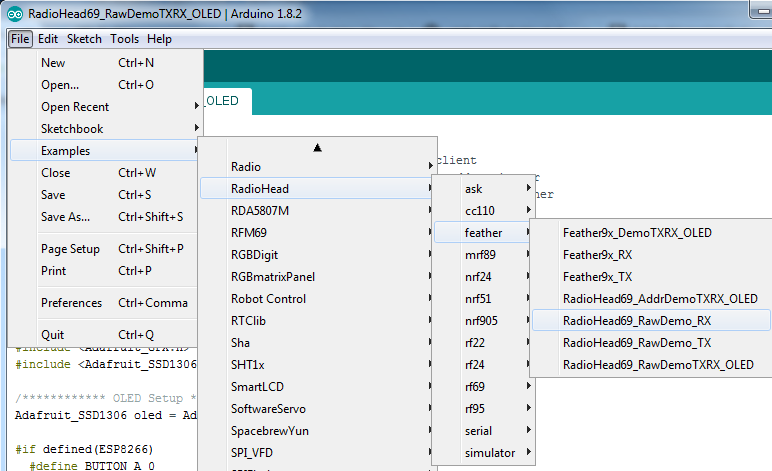
should i also use it at my arduino mega or should i just use the rf95?
stuck coral
quaint cloak
should i also use it at my arduino mega or should i just use the rf95?
The normal rf69 examples not under the feather folder should work just fine with the mega
 spice vapor
I am having a problem with my bluefruit feather sense board.
It's no longer responding to reseting with the button press. It's currently not showing up on USB.
I have checked the cable and it is a data cable. Is there a factory reset method I could try?
stable forge
spice vapor
I am having a problem with my bluefruit feather sense board.
It's no longer re...
if you double-click, do you get the BOOT drive?
spice vapor
stable forge
if you double-click, do you get the BOOT drive?
No, thats where I am currently stuck if I double click the reset button nothing on the board changes
stable forge
does the LED next to the USB jack (on the battery jack side) pulse slow or fast?
spice vapor
the one marked CHG pulses quickly.
stable forge
if the other one is not doing anything, then the bootloader is not coming up. DO you have any inkling that the reset button might be broken? You can simluate it by grounding the RST pin. That is what the rest button does.
leaden walrus
@stable forge my D13 doesn't appear to be driven by bootloader. neopix is though.
leaden walrus
yep. but i could have an older version.
UF2 Bootloader 0.2.9 lib/nrfx (v1.1.0-1-g096e770) lib/tinyusb (legacy-755-g55874813) s140 6.1.1
Model: Adafruit Feather nRF52840 Express
Board-ID: NRF52-Bluefruit-v0
Bootloader: s140 6.1.1
Date: Feb 22 2019
UF2 Bootloader 0.3.2-91-g2df81e6 lib/nrfx (v2.0.0) lib/tinyusb (0.6.0-272-g4e6aa0d8) lib/uf2 (heads/master)``````
leaden walrus
@spice vapor is the neopixel doing anything? larger square one
spice vapor
@leaden walrus nope no other lights, which is also a bit odd.
@stable forge I don't think it would be broken. Bit of a noob here 🙂 but to ground RST what do I need to do .
leaden walrus
"no longer responding" - so it used to work?
stable forge
@leaden walrus would like you to continue here?
spice vapor
Yes, about 30 minutes ago. was working via VScode + platformIO
leaden walrus
@stable forge sure. i can ping you if it seems back in something core land.
spice vapor
have chekced in arduio IDE as well and it's not showing up there either,
leaden walrus
@stable forge before you go - is bootloader protected on nrf?
spice vapor
I assume that it's a board problem as reset should just work ( in theory)
leaden walrus
@spice vapor what was the last thing you did before it stopped working?
stable forge
leaden walrus
<@!329766224093249548> before you go - is bootloader protected on nrf?
yes, though I don't know how platformIO loads things on nRF
leaden walrus
right. nor me.
spice vapor
uploaded a sketch whilst it was connected to a breadboard circuit ( ECG setup ) I then reset and it wouldn't
stable forge
had you used platformIO previously successfully?
spice vapor
Yup!
leaden walrus
is the feather still attached to the breadboard setup?
spice vapor
No, I have discconnected everything so just focusing on getting a blinky example to run again.
leaden walrus
do you have a multimeter?
spice vapor
yes 🙂
leaden walrus
try checking the voltage on the 3v pin
spice vapor
3.27
leaden walrus
in general, need to rule out it haven been zapped by something with the breadboard setup
hmm. ok. that value is good.
spice vapor
Is there a terminal command I can run to see if it can detect it? I remeber running something similar when setting up mu for circuit python
( for annother project )
leaden walrus
how did you verify the USB cable?
spice vapor
I tested it with another board.
I just used ls /dev/tty.* and the bluetooth-incoming-port is showing.
which also shows in the arduino IDE but I can't actually upload to it.
 elder remnant
Hey does anyone know if arduino can run audio files of a voice with just a cheap speaker and regular breadboard stuff? Thanks!
leaden walrus
does that port disappear / reappear as expected if you unplug/plug the USB cable?
spice vapor
oh I am trying the ls command with another board and it isn't showing the USB port either.
So there is definitely something fishy going on. I am going to dig out some more cables and try on another machine as well. But even if the computer isn't detecting the change shouldn't the board go into boot mode with the double tap? Could I test that by hooking it up to a battery pack and testing it?
leaden walrus
yah, it should still do the expected bootloader behavior. but also, fishy things do fishy things.
 pallid grail
@leaden walrus Hiiiiiiiiiii. (Question.)
leaden walrus
could also try forcing DFU:
https://learn.adafruit.com/introducing-the-adafruit-nrf52840-feather/pinouts#user-slash-dfu-switch-3014434-10
and see if you can get a usable port that way
@pallid grail sure
leaden walrus
i think they're touch
pallid grail
Um.... No, that doesn't jive
I ran a touch pin script earlier, and that doesn't match.
That's a physical attribute, right? Not a software attribute?
spice vapor
@leaden walrus thanks for your help I will sing out if anything works or dosn't 🙂
pallid grail
(Sorry for interrupting jen!)
leaden walrus
T1 isn't necessarily D1 etc. would need to check a pinout for ESP32.
pallid grail
hmm.
leaden walrus
to figure out which actual pin those are on
pallid grail
That's straight up a longer list than came out of my script though.
like.... it's too many pins.
I guess some of them could be not broken out pins, but why include them if they're not available?
I have 12 in my script results, and one of the ones listed isn't even available physically.
I guess the ones listed in this file could be entirely arbitrary?
So in the schematic
leaden walrus
got an esp32s2 datasheet?
pallid grail
IO1-IO14 are listed, but IO1 and IO2 aren't even connected to anything
UGH... yes... but it's so obtuse, I really struggled with getting any useful info out of it
Let me pull it up
leaden walrus
looks like they pretty much line up though, like T1 is on D1 etc
pallid grail
There is no D1.....
broken out
Did the Arduino setup for it implement all the ESP pins but not take into account what's actually available on the Feather?
leaden walrus
correct
pallid grail
Oh.
Explains my deep confusion.
Ok. So uh.... On the schematic, the Arduino pins are == to the IO pins?

The only other instance of this section of this template included the CP and Arduino names for the pins. I'm trying to be consistent with my earlier documentation.
leaden walrus
ha! was just grabbing same thing.
pallid grail
Seems like a lot of work, but if it's unclear to me, it'll be unclear to others.
So, better to make it clear.
pallid grail
Right. But A5 is IO8, so it's not all things equal.
pallid grail
Right.
Ok.
Thank you! As usual, I expected this to be a quicker answer than it was. 🙄
Appreciate you taking the time.
leaden walrus
D5 looks like the lowest touch pin available
1 and 2 not broken out. 3 and 4 used for i2c.
yah, and 7 is dedicated to i2c power
here's where the analog pins get mapped:
https://github.com/espressif/arduino-esp32/blob/399f4ecbb3a4cef21e2bffa37adb6190356dfb76/variants/adafruit_feather_esp32s2/pins_arduino.h#L37-L42
A0 would end up being ADC2_CH7, for example
 pallid grail
leaden walrus
1 and 2 not broken out. 3 and 4 used for i2c.
pallid grail
leaden walrus
1 and 2 not broken out. 3 and 4 used for i2c.
But the I2C pins can be used for touch, right?
leaden walrus
if nothing is attached to them
pallid grail
Right ok that's what I meant
leaden walrus
incl on board pull ups
leaden walrus
this is feather esp32s2?
pallid grail
leaden walrus
here's where the analog pins get mapped:
<https://github.com/espressif/arduino-e...
Yeah I saw the analog pins bit.
pallid grail
leaden walrus
this is feather esp32s2?
Yes.
pallid grail
leaden walrus
`A0` would end up being ADC2_CH7, for example
This is where I started struggling to use this datasheet and wished I was back to dealing with RP2040 which was so much clearer to me.
Ooh wait
pullups only on the STEMMA connector?
(I'm still not great at reading schematics)
leaden walrus
there's i2c stuff included on that feather. bme280, lipo monitor
pallid grail
Yeah, right
leaden walrus
so all that will mess up touch
pallid grail
Here is what I have now: A4 A5 D13 D12 D11 D10 D9 D6 D5
A4 initially got caught on the "tell-Markdown-what-kind-of-code-this-is" line.
@leaden walrus Adding an alert: There are other pins that are touch capable on the ESP32-S2 module itself, however, the layout and circuitry on the Feather render them unusable as touch pins. Wording seems weird, but...
leaden walrus
yah. that list looks ok. i think.
pallid grail
It's the touch pin script results minus the ones that don't work.
so it should be correct.
leaden walrus
it might be worth changing that header file in the BSP
then pretty pins would show what's actually available
pallid grail
What is a "header file in the BSP" ?
pallid grail
Ahh.
@leaden walrus Doesn't that involve a PR to espressif?
Oh looks like they're semi-responsive anyway.....
leaden walrus
yep. and worth asking about first. i'm mainly just thinking out loud.
pallid grail
Yeah fair enough.
stable forge
spice vapor
So there is definitely something fishy going on. I am going to dig out some mor...
a "power pack" often doesn't work with the boards because it expects things that draw more current, and shuts down when there's only a small draw. So a 5V AC adapter is usually a better test. Since there's no host connection, when you double-click, you should get a "fast pulse" on the boot LED, which indicates the bootloader is not see a host. Try this on another board to see it for sure.
pallid grail
leaden walrus
yep. and worth asking about first. i'm mainly just thinking out loud.
I'll make a note to ask tomorrow. Limor's been unresponsive this evening to other things on Slack, so I won't bother her.
I could also manually update the PP diagram. Did it earlier too, heh. Such is life.
Faster than regenerating it, tbh.
For something like this.
Anyway. Thanks again, cater.
 regal mural
I can't always get my sketch to upload to my Adafruit Qt py (ATSAMD21). Am I dong something wrong?
Using the arduino IDE
spice vapor
stable forge
a "power pack" often doesn't work with the boards because it expects things that...
@stable forge I tried another board, and it works fine with the cable.
one thing that is odd is if I plug in the problem board it shows :/dev/tty.Bluetooth-Incoming-Port
if I plug it out it still shows the same port after executing ls/dev/tty.*
stable forge
I don't understand macOS's rules for adding ports 🙂
north stream
I think the Bluetooth one sticks around, I'd expect another tty to show up when something is plugged in that provides a serial link.
 native elbow
Working with the ESP32-S2 Feather, I can't figure out from looking at Arduino documentation or googling: how do you implement I2C_POWER in Arduino code for this board. I saw how it was done in Circuit python but I can't find any examples with it in Arduino
livid osprey
native elbow
Working with the ESP32-S2 Feather, I can't figure out from looking at Arduino do...
Should be the same concept, just use I2C_POWER as a pin. The definition should be built-in if you have the correct board selected in the IDE.
For the BME280, configure I2C_POWER as an output and drive low.
If I2C_POWER doesn't work, you can also just use pin 7.
 green thunder
I don't think all the board definitions for the Feather ESP32-S2 are there or are all correct at the moment. I didn't see the power pin in there, and the UART pins aren't defined properly either
livid osprey
Well https://learn.adafruit.com/adafruit-esp32-s2-feather/pinouts is bound to be correct one day...
green thunder
The learn guide is correct!
livid osprey
It is a new board so things may not be perfect yet.
green thunder
Just the Arduino pin definitions for it arent yet lol
livid osprey
It is pin 7 so you can use that for the time being.
green thunder
Unfortunately the learn guide wasn't up yet a couple weeks ago when I was figuring all this out lol
livid osprey
No software change can possibly re-wire your board LOL
green thunder
Truth lol
pallid grail
@leaden walrus ping.
leaden walrus
@pallid grail pong.
pallid grail
leaden walrus
<@!330227457296957440> pong.
Hey. Question about adding to the arduino-esp32 BSP. Limor said "we have a fork, commit there". I see you did something recently with it. Am I supposed to PR to it? Or am I supposed to commit directly?
pallid grail
I feel like that's what Limor meant. But I wasn't sure.
leaden walrus
but in general, i'd prefer to have done a PR
leaden walrus
me too
pallid grail
I guess I'll PR it because it's habit and Limor can approve it.
leaden walrus
yah. PR. let's see what happens.
pallid grail
Thanks!
@leaden walrus It turns out every ESP32-S2 board has every touch pin enabled in the Arduino BSP. 😄
Limor said to update the Feather and "look at the other boards too if (I'm) up for it"
leaden walrus
it's not really "enabling" them, just defining them
pallid grail
Ah
Better wording.
Well, anyway, it's a thing.
Which I will try to update.
I mean, like.... MagTag. Not sure there should be any on that one.
Metro might have them all. We'll see.
leaden walrus
having them in there doesn't really break anything
pallid grail
Fair enough.
leaden walrus
it's more implicit - by having them in there, it implies they are available, which they may or may not be, depending on board
leaden walrus
and then it also affects prettypins
prettypins assumes the arduino board def is true to the specific board
pallid grail
@leaden walrus Any reason TX/RX wouldn't work as touch pins on a Feather ESP32-S2 with TFT? They don't appear to be used anywhere else on the schematic, like SCL/SDA for example. The TFT is SPI.

 rancid heath
The latest 1.3 in display SSD1306 now has a STEMMA connector. Since the QT-PY microprocessor also has a STEMMA connector is there any reason the QT-PY will not work with the SSD1306 using Arduino IDE?
 charred dust
hey guys, I'm using this guide(https://learn.adafruit.com/32x16-32x32-rgb-led-matrix/new-wiring) to wire up a rgb matrix up to my arduino uno. It's the 32x16 variant. The only thing tho is that the pinout on the website is mostly the same for my model, with the exception of the left side being empty and LAT on the pinout being STB on my matrix.

Adafruit Learning System
Hundreds of pixels of eye-blasting LED glory!
is STB and LAT the same?
north stream
STB is "strobe", and LAT is "latch", so basically yeah
native elbow
livid osprey
Should be the same concept, just use I2C_POWER as a pin. The definition should b...
I'm using this AHTXO example code: ```#include <Adafruit_AHTX0.h>
Adafruit_AHTX0 aht;
void setup() {
Serial.begin(115200);
Serial.println("Adafruit AHT10/AHT20 demo!");
if (! aht.begin()) {
Serial.println("Could not find AHT? Check wiring");
while (1) delay(10);
}
Serial.println("AHT10 or AHT20 found");
}
void loop() {
sensors_event_t humidity, temp;
aht.getEvent(&humidity, &temp);// populate temp and humidity objects with fresh data
Serial.print("Temperature: "); Serial.print(temp.temperature); Serial.println(" degrees C");
Serial.print("Humidity: "); Serial.print(humidity.relative_humidity); Serial.println("% rH");
delay(500);
}```
How do I use I2C_Power as a pin in this example? I apologize I'm super new to Arduino and given that I don't see any other code examples using Arduino for the ESP32-S2 Feather I'm at a loss
I realize Arduino is not the best use for this right now, just trying out some basic things while support for ESPHOME on ESP32-S2 is fully there
vivid rock
rancid heath
The latest 1.3 in display SSD1306 now has a STEMMA connector. Since the QT-PY mi...
I am sure QT Py will work with SSD 1306 under Arduino IDE - just use appropriate library
livid osprey
native elbow
I'm using this AHTXO example code: ```#include <Adafruit_AHTX0.h>
Adafruit_AHTX0...
You may have to initialize a TwoWire object manually and add it as an argument to the AHT.begin() function call. The ESP32-S2 feather is still very new so the board built in definitions may not be working perfectly yet…

Honestly, Adafruit typically gives circuitpython boards more attention with regards to circuitpython first, so if you’re looking to do a quick test, that might be the faster way to get the esp32 s2 off the ground.
I can’t explore the limits of the arduino side since I don’t actually have one of these boards. Everything I know is basically verbatim from the learn guides…
brazen falcon
pallid grail
<@!337989520962093057> Any reason TX/RX wouldn't work as touch pins on a Feather...
GPIO1-14 (only) are valid touch pins (Page 12 of the ESP32-S2 datasheet) so if they're not being used for anything else and they were routed someplace usable I don't see why not.
However I haven't stared at the schematic for that particular board so take that with a grain of salt.
pine bramble
Does anyone know how to send the row number inside HTTP request if I want to PUT or DELETE a certain line in google sheet
north stream
It looks like it's encoded in the URL you send the PUT request to, in A1 notation.

Google Developers
 gilded gazelle
@odd fjord, I think you were who helped me a couple days ago, here are pics of the "socket" I created


 odd fjord
gilded gazelle
<@!343570430042308609>, I think you were who helped me a couple days ago, here a...
odd fjord
gilded gazelle
<@!343570430042308609>, I think you were who helped me a couple days ago, here a...
That looks very nice, but I don't recall being involved.
gilded gazelle
this is just to play with flashing, hrrrmmm how do I search old posts
odd fjord
I think it was @livid osprey
in the top right there isa search window -- type in AL_hx2 and search for your posts
gilded gazelle
derp, I somehow missed the big search window, gonna go get my dunce hat
leaden walrus
there are filters too, like from: and mentions:
odd fjord
it has limited capabilities
leaden walrus
^^ and that
gilded gazelle
thanks guys!
odd fjord
It would be nice to be able to search content
gilded gazelle
@livid osprey , thanks
pine bramble
odd fjord
It would be nice to be able to search content
you can just dump years of history from a discord channel
that,s what I did when I joined a discord for a minecraft discord instead of asking bazillions questions I'd search in their archives that way
odd fjord
How do you dump history?
pine bramble
with something like https://github.com/Tyrrrz/DiscordChatExporter that uses your discord api key to do ikt
I don't know if server admins have control over how old the history is or if it's limited by discord staff or if it even still work (haven't had to do it for months)
but it's usually better than the discord search feature because you can grep and regrep in the huge text file
odd fjord
Sounds lie a good approach -- thanks!
 median mica
I know it’s an old product, but I have a 5V trinket(ATTiny85) that will not enter bootloader mode. I followed the guide. The red light is barely bright for as long as I tap the reset button, then it’s off. Did my trinket die?
Also, I followed the guide to repair the bootloader
livid osprey
Did the bootloader successfully repair?
median mica
Yes. That’s what the serial monitor told me. Just like the guide.
livid osprey
What are you connecting the device to?
I remember the device is old bit-bang style, so it's really picky about USB ports?
median mica
I tried both usb from the computer and also tried thru a usb hub
median mica
Let me try again, USB3 interesting
livid osprey
Yeah, you could also make sure that your hub isn't USB3. I know at the time of the guide's writing, USB3 hubs weren't really a thing, but a newer hub could be a problem for the Trinket.
median mica
That was it! Thanks. I found an old USB2 hub and it worked perfect.
gilded gazelle
RE: ESP8266-s3 how safe is it to pull pins hi/lo without a resistor? Only for flashing, not use. I cant find a chassis to yank one from.
 sour turtle
I'm very new to this so i'm not sure if i'm using the right terminology.
Let's say i have 12 RGBW neopixels in my project, according to their site they need a max of 60mA. If i just use the current provided by the usb connection, what will happen when i use all 12?
Am i at risk of damaging anything? Or will they just not light up as bright as they could be
native dagger
60 mA per led if that wasn't clear in the documentation
But that's at full brightness
sour turtle
Yes, 60mA per led
native dagger
What happens depends on your brightness. I wouldn't recommend it.
Either way
Like it might be ok, but a separate, higher rated power supply (with a 1000 uF cap across the power line) is best
gilded gazelle
best case, things wont work, worst case you melt your usb port
native dagger
Yeah its not worth the risk imo
sour turtle
I'm trying to reverse engineer a device that only uses usb, so i'm trying to understand what they did
gilded gazelle
if they have a limiter on the brightness
sour turtle
Usually i'd go the route of trying it out and seeing what happens but i don't like the idea of damaging components
From a computer
native dagger
Hmm they probably have brightness tightly controlled. How critical is it that your device works from a USB port on a computer?
gilded gazelle
I have a dead hub due to a short
sour turtle
It's a controller, if i need a seperate power source it wouldn't be worth making for me
native dagger
Hmm well you can do it, but I would recommend developing with a separate psu and then testing your current at the highest load.
gilded gazelle
did they use neopixels on what you are revEing? or different rgb(w)
native dagger
Before switching over to the computer power
gilded gazelle
use a powered hub thatway you dont hurt desktop
sour turtle
 native dagger
If you don't have a DC current capable multimeter this is a great excuse to upgrade
sour turtle
I think it's a RGBW neopixel but i can only see this one
sour turtle
gilded gazelle
use a powered hub thatway you dont hurt desktop
Thank you, that's fair. I suppose i can do that while figuring things out
You both suggested the same, so i'm thanking both
gilded gazelle
yw
livid osprey
sour turtle
Oh, they usually keep those keeb LEDs at a pretty low brightness. I don’t think they ever push any single channel past 15%…
Unfortunately that’s software controlled, so not a lot of good ways to confirm
sour turtle
I have the software, or a version of it
I'll look into it and come back if i'm not able to figure it out :)
gilded gazelle
will I melt the 8266 if I short pins hi/lo instead of using a resistor?
pine bramble
what's a 8266?
pine bramble
on the positive side if it happens you'll be one of the rare person to have seen iron hot enough to turn into gas
cedar mountain
gilded gazelle
will I melt the 8266 if I short pins hi/lo instead of using a resistor?
It depends on what the 8266 is doing with the pin. If it's an input, no problem. If it's driving the output with the opposite voltage, it could be an issue.
gilded gazelle
cedar mountain
It depends on what the 8266 is doing with the pin. If it's an input, no problem....
just trying to get it visible to flash I have the blue light blinking
not sure how to connect this module to the usb/ttl
everything is on the esp-1 , esp12F , nodemcu, but nothing on the esp8266-s3 other than datasheets
I tried any combo of hi/lo for en & io0
no RST on this module
using a cp2102
so yes I am setting input hi/lo
anyone have experience setting bootmode on this particulare 8266?
gilded gazelle
?
livid osprey
gilded gazelle
everything is on the esp-1 , esp12F , nodemcu, but nothing on the esp8266-s3 oth...
https://www.espressif.com/sites/default/files/documentation/0a-esp8266ex_datasheet_en.pdf can be used as crossreference, since this datasheet is the raw chip that goes into any ESP-8266 product.
Just compare the GPIOs on your module to the GPIOs on the ESP8266EX datasheet, and you can semi-reverse engineer a lot of lower-level functionality that way.
Actually, you can use https://www.espressif.com/sites/default/files/documentation/2a-esp8266-sdk_getting_started_guide_en.pdf and use the WROOM instructions given you can match your pins to the ones given for the WROOM module.
gilded gazelle
thank you @livid osprey
gilded gazelle
that gave me what I needed to find progress, it flashes now but hangs @ Leaving...
Hard resetting via RTS pin...
livid osprey
Oh, by that point flashing is done, and the RTS just isn't resetting the system. Just unplug/replug and you should be set.
gilded gazelle
ok
 wet cairn
can I run a FONA and a Feather off one lithium battery by connecting their BAT and GND pins?
will it explode?
wet cairn
<@&617066238840930324>
 north kelp
@wet cairn Which FONA?
north kelp
@wet cairn This breakout version?

Cellular + GPS tracking, all in one? Oh yes! Introducing Adafruit FONA 808 MiniGSM + GPS, an all-in-one cellular phone module with that lets you add location-tracking, voice, text, SMS and ...
If it’s that one, it has its own charge circuitry, as does the feather. I wouldn’t connect one battery to two charge circuits. There might be another solution, like somehow disabling one of the charge circuits.
It looks like the FONA absolutely needs its own battery, according to the FAQ in the product guide:
https://learn.adafruit.com/adafruit-fona-808-cellular-plus-gps-breakout/faqs#faq-2803390

Adafruit Learning System
A full-featured GSM/GPRS module with GPS as well!
 exotic mason
Hello, I am trying to create sound-reactive LEDs using QT PY board. Still learning the basics. Can someone explain why the code on the left does nothing, while the code on the right lights up the on board NeoPixel? On an Arduino site, I read "pinMode(4, INPUT_PULLUP)" must be used on M0 and M4 boards (like my QT PY board).
 vivid rock
exotic mason
Hello, I am trying to create sound-reactive LEDs using QT PY board. Still learni...
vivid rock
exotic mason
Hello, I am trying to create sound-reactive LEDs using QT PY board. Still learni...
I responded in another channel. In general, in this discord we ask that people do not post the same question in multiple channels, as most participants read many channels
exotic mason
Thanks, first time here. Trying to discern the best place for my question.
zinc bridge
When using the Arduino frameowrk with ESP32, how do I tell when configTime() has successfully updates the time?
cedar mountain
zinc bridge
When using the Arduino frameowrk with ESP32, how do I tell when configTime() has...
At a glance, it looks like configTime() is just a setup function to configure the NTP settings, but the actual time update happens in getLocalTime(), which will return a success/failure result.
 surreal pawn
What small adafruit boards are there that have bluetooth and an IMU? I'm thinking feather sized or smaller ideally.
leaden walrus
feather sense maybe?
https://www.adafruit.com/product/4516
surreal pawn
yep, precisely
leaden walrus
you'd need to do some additional work, software-wise, to create an IMU, but it at least has most (all?) of the basic sensors needed.
surreal pawn
that feather is pretty much a clone of the "arduino nano 33 iot sense" but it's in stock https://store-usa.arduino.cc/collections/boards/products/arduino-nano-33-ble-sense

Arduino Online Shop
The Nano 33 BLE Sense (without headers) is Arduino’s 3.3V AI enabled board in the smallest available form factor: 45x18mm! The Arduino Nano 33 BLE Sense is a completely new board on a well-known form factor. It comes with a series of embedded sensors: 9 axis inertial sensor: what makes this board ideal for wearable dev
(and has a lipo plug and neopixel and no microphone)
leaden walrus
also search the learn system for "AHRS" (Attitude and Heading Reference System)
surreal pawn
oh neat, thanks
leaden walrus
 edgy wasp
Hi, new user here. I have what may be a bricked Adafruit Mag Tag (esp32). Where is the best place to go to find any possible fixes for it?
 safe shell
@edgy wasp what happens to the LED/NeoPixels when you press RESET?
also, if you press-and-hold BOOT, then press RESET, (then release RESET, then RELEASE BOOT) does it enumerate in your list of USB devices?
edgy wasp
It was flashing the neopixels purple. We have gotten access to the file system now, so I may be good. But I spent 30 minutes trying to get there.
brazen falcon
surreal pawn
What small adafruit boards are there that have bluetooth and an IMU? I'm thinkin...
Its not an Adafruit product, but: https://www.seeedstudio.com/Seeed-XIAO-BLE-Sense-nRF52840-p-5253.html

Seeed XIAO BLE nRF52840 Sense is a tiny Bluetooth LE development board designed for IoT and AI applications. It features an onboard antenna, 6 Dof IMU, microphone, all of which make it an ideal board to run AI using TinyML and TensorFlow Lite.
Not gonna get much smaller than that.
surreal pawn
brazen falcon
Its not an Adafruit product, but: https://www.seeedstudio.com/Seeed-XIAO-BLE-Sen...
Neat!
 autumn karma
I've been working with an old digispark-tiny clone (ATTINY85) I had floating around. Apparently this sucker runs with a 16Mhz external clock. Is there a way to change this to reference the internal 1Mhz clock instead and validate it's working as expected?
I should also note I'm using VSCode with PlatformIO. I think there is a platformio.ini variable I might be able to adjust.
pine bramble
start.atmel.com might be helpful there.
attiny85 not listed there but a similar part number is.
and this from the manual pretty much seems to bar it: "The AVR CPU is driven by theCPU clock clkCPU, directly generated from the selected clock source for the chip. No internal clock division is used."
autumn karma
I'll take a look around those video guides. I think there is this 'board_build.f_cpu = 16500000L' parameter in the configuration file too.
pine bramble
I did some bare metal clock work using the start.atmel.com approach.
autumn karma
I'm sorry, I just want to make sure I understand what your saying here too. Is that a web link or a library or sorts?
pine bramble
a guy named Jake Read did a SAMD51 project and wrote some good code wrt some of this stuff.
start.atmel.com is a web site.
It's a GUI configuration tool that generates files you can download (maybe in the .ZIP archive format).
Once you have it downloaded you compile it on your own computer.
(complete source code example that you custom generate)
autumn karma
OK gotcha, I saw the site but wanted to confirm. It looks pretty neat actually. The main guide video on the site is similar to what I'd like to mess around with at the end. An ADC with an interrupt of sorts.
pine bramble
Once you set the main clock then you have to configure serial communications to work with that clock, on at least some chips (if not all of them).
Easier: bit-bang the output (send serial data but do not try to parse inbound keystrokes at all, for example).
That way you can probe the state of the program with a bit more nuance than blinking an LED.
(print typewritten messages you authored yourself)
That's really not too bad if you have an oscilloscope to prototype with.
was done on SAMD51:
https://github.com/wa1tnr/bitbanged-serial-a
autumn karma
yeah, an oscope is like a must here. I have one and I basically just toggle a pin to get the timing information.
Sadly, I can't really use a serial port as a method to debug. This chip has very little memory, and a custom library to bit bang through the USB port would be needed with a ton of other timing related issues that could occur.
Better to just toggle a pin and measure with an oscope.
pine bramble
well we had 768 bytes of RAM on C8051F330D from Silabs iirc and 8kb flashROM.
some fairly serious code ran on that platform. ;)
including a serial bootloader placed in flash using the C2 debug interface on an uninitialized MCU.
(serial bootloading to reflash many times, after)
autumn karma
if your creative enough, you can really push a chip to it's limits even if they are little to begin with. It looks like this ATTiny85 has 512 bytes of RAM and 6012 bytes of flash. Both of these chips seem pretty similar.
pine bramble
It'd be more appealing today if there were nothing better out there at a modest price.
The 8-bit factor I see as a plus, though. ;)
autumn karma
what makes 8-bit a plus in your mind? And yeah, I bought a few of these chips like 5 or 6 years ago. I have a small project I think I can use this for instead of getting another chip.
pine bramble
I have at least 19 of the 25 C8051F330D chips I bought during the brief window when they made and sold 'em. ;)
The only DIP packaged MCU Silabs had that I was aware of.
(DIP-20 iirc)
autumn karma
do you create your own PCBs then for each of your projects? Or do you have a general development board you just slap a chip on and call it a day?
pine bramble
Well a 32-bit machine uses 32 bits of RAM (contiguous) as a storage unit.
So the memory address space is divided by four.
I think.
64 kb works out to 16 k useful addresses.
But many programs do not allow you to go past the 64 kb boundary.
So the programs are 1/4 in size.
I think that's correct.
pine bramble
pine bramble
I think that's correct.
no not at all
otherwise 8 bits chips would be limited to 2^8 bytes of memory ie: not even 0.5kb
0000 0001 0002 0003 0004 0005 0006 0007
0008 0009 000a 000b 000c 000d 000e 000f << 16 bytes
0010 ...
The first storage unit stores data in 0003 0002 0001 and 0000.
Read right to left.
When you read a dump, you find the four-byte boundary and read right to left to get what's stored there.
You can pack it tighter but compiled programs don't work that way, overall.
autumn karma
this is all new to me, but is this the method of how a compiled program is stored in flash (8-bit compared to 32-bit)? wouldn't it make sense to have every byte of information jammed right next to each other?
pine bramble
They don't do it that way.
For an 8-bit MCU it's not an issue.
If I store 1, 2, 3 and 4 the ram dump looks like this:
00 00 00 01 00 00 00 02 00 00 00 03 00 00 00 04
ok, what would it look like for a 32-bit? wouldn't there just be extra null bytes?
pine bramble
If I store 0xc0ffee 4 times it looks like this:
00 ee ff c0 00 ee ff c0 00 ee ff c0 00 ee ff c0
Maybe the 00 is on the lsb side I've forgotten.
ee ff c0 00 ee ff c0 00 ee ff c0 00 ee ff c0 00
I don't have it memorized as I have memory dumps to intuit this.
autumn karma
hold on, I think I know what your trying to say here. So for a 32-bit system, to store a decimal 1, 2, 3, and 4 in memory (big endian) it would have to be something like:
00 00 00 01 00 00 00 02 00 00 00 03 00 00 00 04
but for a 8-bit system, it really should only need to be:
01 02 03 04
Yup.
Each hex digit is four bits wide.
Strings look like this (they use memory more efficiently):
https://github.com/wa1tnr/ainsuMtxd51-exp/blob/master/doc/sample_run_28_aug_a.txt#L7-L13
This: E0 03 00 20
is actually this: 0x200003E0
autumn karma
yeah. and I know even with an 8-bit system you COULD store 16-bit information and do mathematical work with it. The only issue is that it would need to do two step comparisons in 8-bit chunks, where as, 16-bit would do it in one
same applies for 16-bit system doing 32-bit mathematics with data.
autumn karma
pine bramble
This: `E0 03 00 20`
yeah, that's little endian format.
pine bramble
So that's correct. 0x200003E0 is stored as I show it.
Reading right to left. "It is swapped and is grouped in two hex digits"
(8 bits)
So this is how a full 32-bit address appears in your program.
The problem is, much of everything else does, as well. ;)
I'm not really sure on that; other than that's my overall impression from having done disassembly.
At the very least, your program is just peppered with 32-bit addresses.
I haven't yet hit the 64 kb boundary to see how bad the problem really is and what (if anything) can be done to treat for it.
Seems to me the upshot is: you get 16,384 storage 'units' for your lower 64 kb storage (below the 64 k boundary).
autumn karma
Hey, is there a register on this ATTiny85 I can read to see what the flash fuses are currently set to?
north stream
I'm pretty sure there is
 supple quest
alguien pudo conseguir controlar un foco inteligente con Arduino ESP8266 mediante WIFI
brazen falcon
autumn karma
Hey, is there a register on this ATTiny85 I can read to see what the flash fuses...
avrdude -c usbasp -p t85 -u hfuse:r
avrdude -c usbasp -p t85 -u lfuse:r
avrdude -c usbasp -p t85 -u efuse:r
adjust -c option to suit what programmer you're using
autumn karma
sweet, thank for the info!
autumn karma
ugh, so I'm having some issues trying to enable an interrupt for the ADC circuitry for this ATTiny85. This is the code I have so far:
void setup() {
  pinMode(DEBUG_PIN, OUTPUT);

  //ADC Multiplexer Selection Register
  ADMUX |= (1 << ADLAR); //Left adjust 10-bit result leaving 2 LSBs in ADCL register
  ADMUX |= (1 << MUX0);  //Internally connect PB2 (A1) input to ADC circuitry

  //ADC Control and Status Register
  ADCSRA |= (1 << ADEN);  //Enable ADC circuitry
  ADCSRA |= (1 << ADSC);  //Begin a single analog conversion
  ADCSRA |= (1 << ADATE); //Enable auto trigger for 'free running' continuous mode
  ADCSRA |= (1 << ADIE);  //Enable ADC interrupts to occur whenever a conversion completes
  ADCSRA |= (1 << ADPS2); //Sets prescaler division factor to 64, combined with next line
  ADCSRA |= (1 << ADPS1); //(8MHz / 64 = 125kHz, where ADC within 50-200kHz for best resolution)

  //AVR Status Register
  SREG |= (1 << SREG_I); //Enable global interrupt to allow interrupts to occur
}

ISR(ADC_vect) {
  PORTB &= (1 << DEBUG_PIN);
  PORTB |= ~(1 << DEBUG_PIN);
}
am I missing something or attaching the interrupt correctly? I just want to see if a pin can be toggled with an oscope attached to it.
pine bramble
Hello, i am using the NEO 6m GPS module with arduino and TinyGPS++ library, it's giving me the time output but the time is wrong, Only the hours are wrong the minutes the date is fine, So i wanted to know is there any method of configuring that time? How does that time work? Does it gets fetched from the nearest satellite? if it does then why the Time is still wrong even after i tested it in other country
 rough torrent
 gilded gazelle
OST orbit standard time
 willow viper
Um can anyone explain how exactly does adafruit unified sensor driver works ?
Though it's not related to arduino but could be useful to know how it works
I've gone through the guide
So far is it an oops concept for sensors?
odd fjord
OK -- I guess I misunderstood what information you are looking for
willow viper
Ah
I just want to know the concept behind the unified sensor driver
odd fjord
Isn't that covered in the guide? https://learn.adafruit.com/using-the-adafruit-unified-sensor-driver/introduction what are you looking for that is not there?
willow viper
It is
But I got confused on the practicality
Let me get this right
This driver is treating all sensors as same
If there are like two sensors in the same device a unique id is assigned to both to differentiate the sensors
the driver has two key functions, one that reads the data from the sensor and the other the general info of the sensor
Is that it ?
livid osprey
It's not that this driver is treating all sensors the same, but rather defining a standard framework or interface for making sensors interchangeable without too much extra code. It provides a structure for defining units in the driver so users don't have to manually write the code to convert analog voltages or serial data to a human-readable SI unit.
odd fjord
It also means that you can change to a different model (manufacturer) of the same type of sensor with minimal code change necessary.
livid osprey
In other words, the driver doesn't treat all sensors the same, but it allows the user's code to treat similar sensors the same way.
So each separate device still needs its own driver, but if implemented properly, you would only have one definition and one driver to replace*/add* if you ever needed to switch to a different sensor.
willow viper
ah so basically it cannot be applied to all sensors ?
livid osprey
It can be applied to any sensor that senses any of the supported sensor types. However, some less-common sensors may require you to write your own driver for it.
willow viper
what about sensors that follow a different protocol ?
I know most sensors are of I2C
im actually trying to implement this method in a RISCV FPGA side and taking this as inspiration
livid osprey
Since all the sensor readings and conversions are being handled in the driver, the protocol would not be an issue for this.
willow viper
its like driver gets the data
the unified driver converts that data to human language ?
north stream
More like it abstracts the details of the different sensors and lets you access them similarly.
willow viper
oh
so drivers are fixed
the output from that driver gets converted to that human language data ?
how does it know which driver is it using ?
like the BMP_U
 trail swallow
I'm getting confusing results from ```void setup() {
Serial.begin(9600);
pinMode(LED_BUILTIN, OUTPUT);
digitalWrite(LED_BUILTIN, HIGH);
while (!Serial) {
digitalWrite(LED_BUILTIN, LOW);
delay(100);
digitalWrite(LED_BUILTIN, HIGH);
delay(100);
}
Serial.println("Startup");
scale.begin(LOADCELL_DOUT_PIN, LOADCELL_SCK_PIN);
Serial.println("Started");
}``` - I'd expect to see "Startup" and "Started" or at least the first one, or the LED on this HUZZAH blinking, but I just see unprintable characters over serial. Has anyone seen this before?
 livid osprey
willow viper
like the BMP_U
livid osprey
willow viper
like the BMP_U
You would define the sensor when you initialize it.
livid osprey
trail swallow
I'm getting confusing results from ```void setup() {
Serial.begin(9600);
pi...
What type of hardware are you using?
trail swallow
livid osprey
What type of hardware are you using?
I’ve connected a Feather HUZZAH ESP8266 to an HX711 load cell.
I wouldn’t expect that to change serial behavior.
livid osprey
Serial could be a lot of things. First thing I would've suspected would be a baud rate issue, but the numbers look like they match. How is your Feather connected to your serial monitor?
trail swallow
A USB cable
trail swallow
I just uploaded code with it so I don’t think that’s it

Your cell phone charges off of USB, but can you really trust that charging station at the airport? Now you can control when to allow data in or out of your device with this little USB ...
livid osprey
Hmmm
Oh, ESP8266?
I remember something being wrong with clock divisors or something before
https://github.com/esp8266/Arduino/issues/4005
This may sound weird, but try setting the baud rate in your program to 74880, and your monitor to read in 115200...?
GitHub
Basic Info Amica NodeMCU ESP8266MOD to Arduino IDE gives garbage / gibberish serial monitor output. Note that the Blink examples function perfectly (both native Arduino and ESP8266 versions). The o...
trail swallow
Ooh, weird, I’ll try that, thanks.
trail swallow
Using 74880 in both places was what worked in my case.
9600 is working now, as well. As to why... I do not know.
livid osprey
74880 is just a weird magical number for Espressif. Why or how is anyone's best guess....
trail swallow
That's unsettling.
Do you know of something ESP8266-ish that's more robust?
The ESP8266 ecosystem with things like esphome and wled is hard to beat, but the low memory and high power consumption are pretty rough.
livid osprey
ESP32 would be the way to go. Much better memory, and added ULP and deep sleep functions for saving power.
Essentially the same ecosystem, but much better specs all around.
trail swallow
Oh wow! Very nice. I hadn't realized the ESP32 was a sequel. I had... actually assumed that more numbers meant more recent. :o
I see the ESP32-S2 also exists but is very early days.
livid osprey
I wouldn't say VERY early, it's pretty stable now and people are starting to develop for an ESP32-S3 eval board...
The ESP32-S2 does have the added benefit of being supported by Circuitpython, if you're interested in that.
trail swallow
I think I got it confused with something that didn't have Arduino support.
vivid rock
that would be esp32-s3
livid osprey
The non-S2 is actually more powerful than the S2, and packs bluetooth in there as well. No CP, but it's got a dual core proecssor with a 240MHz clock speed or something
ESP32-S3 isn't supported by Arduino yet, but is in the works. The ESP32-S2, on the other hand, is all over Adafruit's product lineup. Magtag, feather, etc...
trail swallow
Interesting. I get the sense I stand at a crossroads between continuing on WiFi and moving to zwave or zigbee for home automation.
trail swallow
livid osprey
The non-S2 is actually more powerful than the S2, and packs bluetooth in there a...
I did notice that, yeah. Dual core is definitely compelling.
 lavish glen
Hey quick question, got an HUZZAH32 ESP32 over here. Going through the docs atm and on one page it says that once WiFI has started ADC #2 can only READ analog inputs, but then in the FAQ it says it can't once Wifi started. So, which one is it?
solemn cliff
lavish glen
Hey quick question, got an HUZZAH32 ESP32 over here. Going through the docs atm ...
looks like the correct info on the ESP32 is that ADC2 is used for wifi and therefore unavailable when wifi is running, unless you do some low level lock gymnastics or something. You can use the feedback link on the guide to signal the error in the pinouts page.
https://community.blynk.cc/t/interesting-esp32-issue-cant-use-analogread-with-wifi-and-or-esp-wifimanager-library/49130
willow viper
Ok just to be clear
Is this how the unified sensor works ?
 safe shell
lavish glen
Hey quick question, got an HUZZAH32 ESP32 over here. Going through the docs atm ...
safe shell
lavish glen
Hey quick question, got an HUZZAH32 ESP32 over here. Going through the docs atm ...
if you don’t need wifi continually and adc doesn’t mind a break now and then, you should be able to turn wifi off and on at will and use ADC2 in the times when it’s off
vivid rock
As of now, there are (unless I am much mistaken) two arduino cores for RP2040:
an official one, based on MBed OS: https://github.com/arduino/ArduinoCore-mbed
and arduino-pico by Earl Philhower: https://github.com/earlephilhower/arduino-pico
Can anyone comment on advantages/disadvantages of each of them? Which one should I use for my project?
vivid rock
Thanks!
do you have some personal experience with either core?
livid osprey
I haven't used either extensively past some VERY basic sketches, so I don't have a direct comparison to make, I'm afraid.
pine bramble
@vivid rock Go with Earle initially.
If you know and like CMake you can use the pico-sdk natively.
vivid rock
well... I know little of it and what I know, I don't like :)
pine bramble
CMake was a hard learning curve for me.
vivid rock
I could do it this way if necessary, but I'd prefer simplicity of Arduino IDE setup
I will try Earl's core then
 clear fog
Would anyone be able to help me with understanding if loops on a esp32?
having trouble figuring out how to exit a loop
faint raft
clear fog
Would anyone be able to help me with understanding if loops on a esp32?
having t...
In C or in Python? I assume C?
clear fog
yes C
I'm trying to have the while loops run until a new character is sent via Bluetooth
but at the moment it does not go and recheck the inData string and just loops forever
faint raft
well, you can use break to exit out of the loop
break statement in C, The break statement in C programming has the following two usages −
clear fog
Pastebin
Pastebin.com is the number one paste tool since 2002. Pastebin is a website where you can store text online for a set period of time.
faint raft
So, what do you want this code to actually do?
Let's start there, and then let's address the loops and whiles and stuff.
clear fog
faint raft
well, you can use `break` to exit out of the loop
Thanks, will this allow me to have "b" loop until "a" is received via Bluetooth
faint raft
but, why are you looping here waiting for b or a?
clear fog
I have a bluetooth app on my phone that has a number of buttons that will send: a or b
faint raft
@clear fog take a look at these examples, they might help you... https://github.com/espressif/arduino-esp32/tree/master/libraries/BluetoothSerial/examples

GitHub
Arduino core for the ESP32. Contribute to espressif/arduino-esp32 development by creating an account on GitHub.
clear fog
will be toggling some relays/transistor switches
clear fog
faint raft
<@!668790998121578506> take a look at these examples, they might help you... htt...
That was the code I started with, it does not help me with the loop break on when "inData" changes
faint raft
hmm
so, loop() in itself already loops
so maybe try to remove the while loops and just do the reads that way?
clear fog
hmmm
 sacred ivy
willow viper
Ok just to be clear
Is this how the unified sensor works ?
sacred ivy
willow viper
Ok just to be clear
Is this how the unified sensor works ?
What program did you use to draw this?
pallid grail
@leaden walrus What would make my QT Py RP2040 not show up as a serial port to Arduino? I tried bootloader and not mode. By "not" mode, I mean it's running whatever sketch shipped with it. Neither mode shows up on serial. Reset, restarted Arduino....
This isn't a good board to start with anyway because it doesn't have a built-in LED. But still. Grabbing a Feather anyway.
No port here either. Also running shipped demo.
I vaguely remember having to put these boards into the bootloader the first time after running CP to get them to show up properly to Arduino, but that's not this case.
leaden walrus
@pallid grail i don't think you get a port in bootloader mode, you'd need to drag a UF2 at that point. so may have something to do with whatever is currently on the board.
pallid grail
They're both running tester code.
And I'm not getting a port.
QT Py is NeoPixel swirl, Feather is NP swirl with blinky red LED.
leaden walrus
also try just leaving port unselected
pallid grail
Oh.
leaden walrus
the upload process is a little wonky. it creates a UF2, puts board in boot mode, copies UF2 to RPI-RP2, then resets
pallid grail
Error. No drive to deploy.
pallid grail
That worked.
NeoPixel is still on because nothing told it to turn off 😄
But it's doing slow blink now.
I'm um.... not going to explain all of this in the template.
@leaden walrus Should I at least note the caveat that if it's the first time loading a sketch, you might need to bootloader? Because I think it's a thing when moving from CP to Arduino too....
"to bootloader"? what....? 😄
leaden walrus
probably worth it
pallid grail
Ok
leaden walrus
and can make it generic, like "if you get in weird state and can't upload, put in bootloader, make sure RPI-RP2 shows up, try again"
pallid grail
Oh good call
livid osprey
Isn't there a tool to convert an Arduino sketch to a UF2?
pallid grail
My idea was way more complicated than that.
leaden walrus
@livid osprey yes
livid osprey
Does that work for loading sketches to RP2040? Is it reliable?
pallid grail
I mean once you get past this, uploading normally is reliable.
This funky stuff is only on your "first" go, in my experience.
leaden walrus
@livid osprey it's the same general process used for circuitpython:
https://github.com/adafruit/circuitpython/blob/8eee16c7aad035388fcf895e3aebb098c2c53661/ports/atmel-samd/Makefile#L399
leaden walrus
@pallid grail it ends up using uf2conv.py to "upload the sketch" and that ends up looking for the RPI-RP2 folder
pallid grail
leaden walrus
<@!330227457296957440> it ends up using uf2conv.py to "upload the sketch" and th...
Fair enough.
Nothing is ever simple 😄
leaden walrus
python3 -I uf2conf.py --serial /dev/ttyACM0 --family RP2040 --deploy sketch.uf2
something like that is what is used to "upload the sketch"
livid osprey
It does say on the product page that arduino core wasn't supported at launch, so I assume it should've come preloaded with micropython?
pallid grail
No, we've never flashed MP onto anything to ship it.
I don't know if these were launch-time boards or not.
Arduino core for RP2040's been functional for a while now.
Unstable, but functional. It's stable now.
Might have been good enough for tester code at launch though.
I don't remember what we shipped them with.
Maybe CircuitPython, really. Though that's rare.
These definitely weren't running CP though.
pine bramble
hello, i would like to know if anyone can help me with the Grove-W600 module. I managed to configure it in APSTA mode. Now I wish I could communicate with him from my cell phone. How can I do this? I am new to programming on Arduino. Excuse me for my English, I am French. Thanks in advance.
pallid grail
@livid osprey You around? And how's you're Arduino skills? I have a question 😕
pallid grail
Ok
If I have a sketch, with a pin in it, that's a pin name, i.e. LED_BUILTIN, and the pins_arduino.h or whatever file it is in */variants/board_name/ that defines pins doesn't have that pin defined, will the sketch still load onto the board successfully? Or will it fail because the pin isn't found or some such?
Basically, that pin is 13, but the Blink sketch built into the IDE now has LED_BUILTIN as the pin.
But I checked the RP2040 boards, and Limor called it PIN_LED instead of LED_BUILTIN. And I'm wondering whether the code will still load, but just not work.
vivid rock
pallid grail
Ok
I expect it to throw an error
pallid grail
Although, I'm confused, because I guess I answered my own question - I loaded the basic blink sketch on this RP2040 and it's working.
Me too!
vivid rock
which core are you using?
pallid grail
Philhower core
// LEDs
#define PIN_LED (13u)``` from the variants/board_name/pins_arduino.h file for the Feather.Basically I'm trying to make these guide templates that use the Blink sketch
and I want to say "open it from the IDE menu:"
but I'm wondering whether it will fail for some folks.
vivid rock
indeed
pallid grail
But it didn't just fail for me, which I really feel like it should have....
I can include a basic Blink sketch embedded into the template as code, but if I can use the built-in one, it would be easier....
Arduino isn't smart enough to simply equate a pin name with its default pin, is it?
i.e. LED_BUILTIN is really 13, so if it doesn't find the pin name, default to using 13 instead behind the scenes.
vivid rock
😊
pallid grail
So we're still in the if-the-pin-isn't-defined-it-should-throw-an-error camp here overall.
vivid rock
yes
pallid grail
I'll check the ESP32-S2 boards and see if they all have LED_BUILTIN since that's what this template is for.
Thanks!
vivid rock
anytime
livid osprey
Actually, I don't think it'll necessarily throw an error. Pin 13 might be used across the board, as I believe that constant is built into the IDE.
I think it's only redefined for Arduinos that use a different pin for it.
livid osprey
If you try it with a Pico, for instance, I wonder if it'll show up on pin 13 instead of its actual LED (GP25)
pallid grail
(All the ESP32-S2 boards have LED_BUILTIN anyway.)
Pico pins file: #define PIN_LED (25u)
(I had the core pulled up already anyway)
livid osprey
I don't think there's any code inside the IDE to check for a PIN_LED definition and link that to LED_BUILTIN, but the Pico is definitely a board where that pin differs from Arduino default, so I'd use that to figure out what's actually happening.
I'd test it myself if I had Philhower Core installed, but I've been using Mbed OS for a while now, simply out of laziness...
pallid grail
No worries. The Pico would work because of that generic def in the Philhower core.