#help-with-arduino
1 messages · Page 101 of 1
 gilded swift
Vout = Vin * R2/(R1+R2)
Vout is 3.3V, Vin is 230V, R2 is 100ohm
That gives us
3.3V = 230V * 100/(R1+100)
Just solve for R1
 brazen falcon
What are you trying to accomplish?
gilded swift
But I’d just use a transformer
Like a 46:1 transformer with a full bridge rectifier and a 3.3V DC to DC converter to take the 5VDC out of the transformer to make 3.3V
If I was designing a power supply of course
 north stream
Many simple power supplies use a lashup known as a "capacitive dropper" to reduce mains voltage to something that can power things like LEDs. It's more efficient than a resistive dropper. However, both capacitive and resistive droppers are "non-isolated", which means that anything connected to them is also connected to mains voltage: this should only be done in apparatus that cannot be touched while it is energized. These techniques also only work well in situations where the load is known and doesn't vary much, as the amount of voltage they drop depends on the amount of power consumed: consume less power and the voltage goes up. A transformer is safer for you (it provides isolation, avoiding shocks and fires) and safer for your equipment (its voltage drop does not vary nearly as much with changes in load current).
 vivid rock
If you want to power 3.3v electronics from 230v AC, then no, resistors are not the way to do it. If you only need a relatively low current (say, just to power an arduino), an easy and cheap solution would be to get a USB charger (from 220-230V AC) which gives you 5V DC, and then add a 3.3v voltage regulator
 heavy star
Might also be able to find a 3.3v power adapter, although I haven’t seen many
gilded swift
heavy star
Might also be able to find a 3.3v power adapter, although I haven’t seen many
5V adapter with a 3.3V LDO is a great option
 pine bramble
230 VAC isn't hobby-level working environment.
Generally you buy things that plug into that, and, ideally, have been approved for safety.
(UL rated stuff is becoming harder to find!)
30 volts is considered the electrocution hazard threshold. (<30V not usually a problem)
gilded swift
i think the question comes down to should you, because you certainly can but you probably shouldn't
pine bramble
We moved when I was not yet six years old and I'd already been electrocuted by then - unplugged a fish tank at a neighbor's. ;)
After the first one I instantly recognized the feeling when I got the second one (quite a few years later).
Cement floor basement, outlet wired incorrectly (I did nothing wrong/unexpected).
gilded swift
whoops lol
pine bramble
Several times on outdoor stages I've seen musicians touch a metal microphone/stand and let out a light yelp. ;)
If I was the <gov't> I'd go into stores and pull goods off the shelf that are not UL rated, and let the industry respond to that pressure.
It's ridiculous that there's no enforcement anymore.
No UL mark on this one (I bought mine through DigiKey):
https://www.sra-solder.com/korad-kd3005d-precision-variable-adjustable-30v-5a-dc-linear-power-supply-digital-regulated-lab-grade
FWIW it's built well and would 'probably pass' a UL cert program, unmodified.
Does have a CE mark iirc. /thread
 livid osprey
While UL is federally approved to perform safety testing, it is not a government entity, so requiring UL certification on every product in distribution is probably not enforceable. I would certainly hope every product has some official safety testing done, but UL is a private for-profit organization that certainly does not have to be the exclusive mark of safety on consumer goods.
Main reason UL isn't as common as it used to be: They transitioned to a for-profit organization in 2012.
CE is probably more common for consumer products, since it is legally required for most consumer electronics to be distributed in Europe?
pine bramble
@livid osprey The rub I'm getting is that business practices were relied on in lieu of enforcement - it was always related to national fire codes.
pine bramble
Right the CE mark in Europe - but it doesn't guarantee a whole lot.
(see also #general-chat)
 midnight gulch
UL is usually required if the item has a mains voltage attached power supply, it is there to try to make sure you are not liable to get zap by mains voltage due to bad design. CE is for electronics to built to a country specifications, a FCC is US for the device transmits something and could potentially interfere. RoHS is so kids don't lick them for the lead since it's supposed to be built without lead and other more toxic materials.
We had to go through all the testing and such for some devices we wanted built here at where I work
We got real familiar with the process
 jagged haven
Hey, everyone. I'm trying to fit an M4 Express and Prop-Maker FeatherWing into a 1" pvc pipe. This small space prevents me from powering them via the M4's JST port with my 3.7v 2200mAh battery. I've considered soldering a micro-usb cable to the end of the battery's cables and using that port instead, popping the JST port off the board and soldering my own longer cables to the pins left behind, and directly soldering the battery to the board itself. All of those seem like I'm asking for trouble. Any suggestions?
Relevant power management docs page: https://learn.adafruit.com/adafruit-feather-m4-express-atsamd51/power-management#alternative-power-options-3016710-14
north stream
I think those are all reasonable approaches. I'd probably lean toward using the micro-USB, since a) it's already there, and b) you can unplug it easily, but tack soldering wires to the JST connector pads would make sense too.
jagged haven
If I went with the micro-usb approach, does it matter that the board would expect 5v and the battery would only output 3.7v? I’m guessing the board’s voltage regulator would sort it out but I want to make sure
north stream
Hmm, good point: it might work, but I'm not sure.
jagged haven
Ok, I’ll look for that answer and do the JST approach if not. Thanks for the help!
 vocal quarry
Hi all. Having some trouble getting this Adafruit SD card breakout working. I've tried it with the metro m4 in the attached picture and an old mega 2560. I tried two different SD cards formatted fat16 and 32. I've been using the Card info Arduino sketch. I set the chipselect pin to 10 I'm not sure what else could be keeping the card from being recognized.

 cedar mountain
vocal quarry
Hi all. Having some trouble getting this Adafruit SD card breakout working. I've...
cedar mountain
vocal quarry
Hi all. Having some trouble getting this Adafruit SD card breakout working. I've...
It's not immediately obvious to me that pins 11-13 are the correct hardware SPI choices on the Metro M4. You might need to use the ones on the six-pin header at the bottom of the board, or otherwise double-check what peripherals the GPIOs are getting assigned to.
vocal quarry
cedar mountain
It's not immediately obvious to me that pins 11-13 are the correct hardware SPI ...
Okay that's a good idea. I had done some looking around for a detailed pinout for the M4. I'm not sure if one exists yet, I couldn't find it in the learn documentation. I'll update once I try the six-pin header. Thanks for the quick response 😄
vocal quarry
cedar mountain
It's not immediately obvious to me that pins 11-13 are the correct hardware SPI ...
After some rewiring and trouble shooting the SD card is showing up! Thank you for your help the six-pin worked great 🙂
pine bramble
i am little bit scared... what is this...?

 native dagger
Incorrect baud rate usually
It's way less scary than it looks
Oh wait
Hmm, I'd check baud rate for sure but it could be something else
 safe crown
question for the arduino + compiler pros here : I have custom arduino core for the SAMD51 (M4F) for a board that would be similar to the itsybitsy M4 for some of it. I'm currently on gcc 2017 and previously migrated the toolchain from 2014, also upgraded CMSIS to the latest adafruit version
now using the 2019 gcc is attractive because I'm still saving 3% of flash but "nothing works". I have huge issues to boot the board, large incoherence in just accessing an array of uint32_t, returning crazy values. My SD card driver (custom) works and the board now boots after fixing a couple of SPI related issues but I'm wondering if the move to 2019 required other complicated things in the core, ld script (checked, no difference...) or code ?
 safe urchin
Does anyone else have issues with trying to connect to an arduino?
I got an adafruit metro and I am trying to just connect to it but no luck.
cedar mountain
safe urchin
I got an adafruit metro and I am trying to just connect to it but no luck.
One problem that comes up semi-often is people accidentally using a charger-only USB cable instead of one with the full data-connection wiring.
safe urchin
cedar mountain
One problem that comes up semi-often is people accidentally using a charger-only...
I use this cable to connect to my portable scanner and headset so I think it is a full data connection
cedar mountain
safe urchin
I use this cable to connect to my portable scanner and headset so I think it is ...
Cool. Does the board show up as a USB device in your OS device manager?
safe urchin
cedar mountain
Cool. Does the board show up as a USB device in your OS device manager?
When I plug it in it causes the device manager to refresh but it doesn't show it under ports
livid osprey
jagged haven
Hey, everyone. I'm trying to fit an M4 Express and Prop-Maker FeatherWing into...
The JST port is probably the better way to go; you can desolder the board connector and solder one of these in its place: https://www.adafruit.com/product/3814

For a really long time we assumed that the JST PH didn't have a free-hanging male header version. But then we found this JST-PH 2-pin Male Cable, and we were like, this is perfect! ...
Just make sure you triple check the polarity before you connect your battery haha
jagged haven
I actually just finished popping that port off and repurposing it into a connector like that. It all works but I’ll be ordering one of those soon
safe urchin
cedar mountain
Cool. Does the board show up as a USB device in your OS device manager?
Figured it out. Didn't have the drivers installed
safe urchin
@cedar mountain any idea what board I am suppose to use? A guide online said SAMD but I do not see the metro
cedar mountain
safe urchin
<@!382380426628562955> any idea what board I am suppose to use? A guide online s...
I'm not familiar with that config off the top of my head, I'm afraid. Possibly the guide is telling you to use a similar board using the same microcontroller chip, if the Metro isn't explicitly listed.
safe urchin
Yeah I wish I could just search it on the board manager but sadly that is not the case
sigh I needed to do the more board url thing
 fickle cave
Im trying to power a mosfet using my arduino uno r3(At high frequencies) I found a frequency library that works great, but it only outputs 2.4v when I need atleast 4 to toggle the mosfet gate
north stream
The Uno R3 should output nearly 5V.
You can, of course, build (or buy) a gate driver
fickle cave
it is 5v when im not using the frequency changer code, but when I do it changes to 2.5
vivid rock
if you output a 50% duty cycle pwm signal on a 5v pin, and measure the result using voltmeter, it will show about 2.5v
in reality voltage oscillates between 0 and 5v, but too fast for a voltmeter to react to it
fickle cave
Im oscillating at 60hz, use the voltmeter(ac) and it still measures 2.5, if I oscillate at 1hz and check it(with dc meter) it shows 2.5
I also know that its not actually going from 0-5v because I had the mosfet working without the frequency changer code, but when added it doesnt work
vivid rock
there is no way, as far as i know, of actually changing the voltage of output pins on Uno (assuming power supply provides enough current to feed it). All you can do in code - wharever library you use - is have the voltage switch between 0 and 5v
so i would suspect somethingis wrong with the wayyou measure it
fickle cave
fixed it lol
north stream
pinMode()?
 dull fjord
I need some general help right now, then more specifics later. Here is the long and short of what I would like to accomplish. I would like a raspberry pi to wirelessly control multiple Arduinos. These Arduinos will be controlling light strips. Basically, one Raspberry Pi master, multiple Arduino (or other microcontroller capable of doing this) slaves. I would then like to be able to create a GUI on the Raspberry Pi to control the lights (via the slaves), and maybe even control the lights from my phone?? Does this system I have described even sound possible?
gilded swift
Sure, set up ESP32 or ESP32-s2 microcontrollers with a web server on each with path based commands
Then have the raspberry pi navigate to each ESP32’s address/path combo to send those web commands
Also, for the sake of more inclusive terminology with your setup, try to use Main/Secondary or even primary and secondary. There is a push to move away from using master/slave in technical contexts
Anyway, let me see if I can find a good guide on the Adafruit learning site
dull fjord
Hmmm… I actually always did wonder how we were allowed to use master/slave anymore with today’s political movements. Okay, I will watch out for this in the future. That is just what I learned in college and am used to calling them, so forgive me if I forget and use it.
In response to what you said, I’m interpreting that is I would need to have the program contact each individual microcontroller separately and send the command? No general “mass command” that any secondaries on that “frequency” would pick up and apply, similar to an infared setup?
gilded swift
You could probably query the network in mass for 200 responses for <>.<>.<>.<>/path
dull fjord
Could you find me any guides or examples where a main/secondary wireless setup using these chips was done that I could reference?
gilded swift
Not yet. You might look at whippersnapper as an option
Let me find that learn guide
@dull fjord take a look at this: https://learn.adafruit.com/quickstart-adafruit-io-wippersnapper

Adafruit Learning System
New to Adafruit IO WipperSnapper? Start here.
It would remove the Raspberry Pi aspect and provide a nice interface
Plus no code 🙂
Or minimal at least
I’m not sure how you could do multiple on one instance but perhaps there is a way to control each instance with one dashboard
dull fjord
But wouldn’t this limit me in how much I could have the secondaries (I.e. lights) have custom interaction with a program I develop? For example, I have an alarm clock programmed on my raspberry Pi, and I want the lights to slowly turn on before the alarm goes off. Would I still be able to do this with this type of control?
gilded swift
Oh I see, perhaps there is a way to manage that. I’m not entirely sure though.
So you could connect your wireless devices to Adafruit IO and send commands to your connected Adafruit IO devices

Adafruit Learning System
Want to connect your project to the Internet? Start Here!
 lone lantern
what flash does the macropad have? trying to determine write cycles
 solemn cliff
it's in the 100 000
lone lantern
that's plenty for basic settings, thanks!
won't even bother wear leveling, praise be laziness
livid osprey
lone lantern
what flash does the macropad have? trying to determine write cycles
GD25x16? x being a wildcard.
https://learn.adafruit.com/assets/103270
solemn cliff
lone lantern
both are min 100k
solemn cliff
they might switch chips due to availability, but as far as I know they target 100k min
 sage raven
Anyone know of an alternative to this?
Looking for a header pin/DuPont power bus..

 leaden walrus
looks pretty simple. how important is that form factor?
sage raven
The smaller the better. I could always just cut out some strip board or something I guess
Might also make a design & get some printed - I could see myself using them in a few applications where I need to power different sensors
 lyric seal
Can someone help me with the arduino uno connecting to the Bluefruit? This is how I have it connected but I’m using the Bluefruit UART LE friends and everything online is with the SPI. I’m using the only library you can find and I think I have it wired wrong and the code won’t factory reset
leaden walrus
@sage raven if cutting up something existing is an option, checkout the various perma-proto boards:
https://www.adafruit.com/category/124
could cut out their power rails and the solder on headers
@lyric seal which bluefruit product are you working with?
is it this one?
https://www.adafruit.com/product/2479
 odd willow
Hello! Noob alert! I have made a setup with one arduino which controls a 5v fan and a digital ledstrip. I want the fan to go on/off with programmed intervals and at the same time I want the leds to fade on and off. I wrote a code but now they work one after the other (first the led fades in and out one time and after the the fan goes on and of one time and then the led again) instead at the same time. I can't figure out how to fix it. Here also the beginning of the script. Can someone give me a hint how to fix it?
 livid osprey
odd willow
Hello! Noob alert! I have made a setup with one arduino which controls a 5v fan ...
livid osprey
odd willow
Hello! Noob alert! I have made a setup with one arduino which controls a 5v fan ...
Currently, the way your code is structured to run the entirety of RGBLoop() before proceeding to ventilator(). If you wish to concurrently control your LEDs and fan, you'll have to restructure your code to update your LEDs (showStrip()) and whatever controls your fan once per loop() execution. If you use global variables, you can free your code from the for-loop and increment/decrement your LEDs as you adjust your fans.
int brightness = 20;
int ledState = 0;
bool direction = false;

void loop() {
  switch(ledState) {
    case 0:
      if(direction){
        brightness--;
        if (brightness <= 20){
          direction = false;
        }
      }
      else{
        brightness++;
        if (brightness >= 255){
          direction = true;
        }
      setAll(0,0,k)
      break;
  }
  showStrip();
  // insert fan code here?
  delay(10);
}```No idea what your fans are doing, I just randomly spun up some code based on your current LED function.
 livid osprey
odd willow
livid osprey
odd willow
I just provided a starting point for you to revise your code, because I was worried my phrasing of things would be more confusing than some sample code. I'm sure you can take a shot at rewriting the rest of your code based on what I showed you.
odd willow
yess thank you I gonna give it a try!
sage raven
thanks for your help @leaden walrus
ended up finding the same product in stock at amazon https://www.amazon.com/dp/B08G1D97YY/ref=cm_sw_r_cp_api_glt_fabc_M4JZ92XH335K4AB6TTC0

10pcs Dupont Terminal Block 25p Needle Male Splitter pin Header 2.54 DIY Electronic Building Blocks
awesome little porto boards from adafruit though! keeping those in mind for future projects
livid osprey
If you're just doing 3-dimensional impulse detection, directional resolution would be a function of both refresh rate and separation distance. With speed of sound at 343 m/s, and an arduino analog input having a refresh rate of around 9600Hz for a 328p (Uno), you're looking at a separation distance of at minimum 343/9600-36mm for a minimally functional directional detection.
If we were to go a step further and try to recognize the direction of a particular sound or multiple sounds, you're probably going to need to compare frequency spectrums, at which point you're going to be limited by your significantly lower FFT sampling rate. I don't even know if Arduino is capable of FFT processing, but it'll likely require hundreds of times more separation distance for a hobbyist system to perform directional audio filtering by parallax...
cedar mountain
Agreed, I'd aim for an Arduino-compatible Cortex M4 board with the DSP and floating-point processor rather than trying to do this with a low-end 8-bit Arduino.
The exact board probably won't matter a ton, as this is mostly an audio-circuitry and software problem, but the Feather M4 Express should be a good default choice: https://www.adafruit.com/product/3857

It's what you've been waiting for, the Feather M4 Express featuring ATSAMD51. This Feather is fast like a swift, smart like an owl, strong like a ox-bird (it's half ox, half ...
cedar mountain
Only vaguely. Almost any MCU should be able to run the ADC fast enough to keep up with an audio signal. The reason you need a fast CPU is for all the data-processing after that.
Correct. You'd also only have enough RAM to store a small fraction of a second of audio data at a time on an Uno.
You can choose other available boards. You would probably want to look for a Cortex M4 or M7 processor.
It's much better than an Uno, but the Due uses a Cortex M3, so it doesn't have floating-point or DSP instructions.
That's an excellent option, yeah.
Good luck!
 nimble finch
Hi! I am trying to adapt a pybadge(adafruit) sketch to a esp32 in ARDUINO IDE. The problem is the Arcada library. At some point it uses arcada.timerCallback(...). How can I use something else that works the same for esp32??
Thank you by the way...!
lyric seal
Does anyone know how I would be able to connect a Bluefruit LE UART friend and a MPU 6050 sensor so that the MPU 6050 sensor would send its data to the bluefruit and then to my phone? Everything is currently running just through the Arduino but I'm not sure if because how its wired right now is the reason that the bluefruit will not recognise the data. I have a breadboard available to wire the sensors through but I'm just not sure where to start?
 vivid rock
ble uart friend is supposed to connect to a microcontroller and communicate over serial; mpu6050 communicates with the mcu over i2c, acting as an i2c slave. I am afraid there is no way to avoid having an mcu between them
but you can replace ble friend and arduino by a single device, a ble-capable microcontroller such as itsybitsy nRF52840
lyric seal
Sorry super new to coding, what is an example of an mcu I could use?
vivid rock
as I said, ItsyBitsy nRF52840 would work well

What's smaller than a Feather but larger than a Trinket? It's an Adafruit ItsyBitsy nRF52840 Express featuring the Nordic nRF52840 Bluetooth LE processor! Teensy & powerful, ...
 feral forum
Hello all, can anyone confirm if the Adafruit 1.8" with joystick shields work with Arduino Due (V3.3) boards? I am reading that there are logic level converter on the Adafruit and see conflicting info about whether it should be compatible on the Adafruit site (incompatible libraries potentially). Any help is appreciated.
livid osprey
lyric seal
Does anyone know how I would be able to connect a Bluefruit LE UART friend and a...
I mean, there is an Arduino Uno already wired, so the issue here isn't an issue of a lack of MCU. I checked the datasheets and both devices are 5V-safe, so there shouldn't be any compatibility issues there. I don't see any power wiring, though, so you probably need to wire from the 5V + GND pins to your breadboard, and power Vcc pins that way.
GPIO pins aren't capable of much current, so you shouldn't use them for supplying power to more than an LED or two.
lyric seal
@livid osprey Both devices are connected to the Arduino and working as they should be. I'm just not sure at this point wether they are compatible with eachother? I'm also not totally sure what power wiring is?
lyric seal
vivid rock
https://www.adafruit.com/product/4481?gclid=Cj0KCQjwlOmLBhCHARIsAGiJg7nFzD5CRgKk...
Unfortnuately I have to use what is already given to me 😦
livid osprey
lyric seal
<@!98211350907490304> Both devices are connected to the Arduino and working as t...
Bluefruit, if I recall correctly, should just be sending data over UART, so there should be no issues with hardware. Power wiring is just the wires that connect Arduino 5V to device Vcc and Arduino GND to device GND.
lyric seal
livid osprey
Bluefruit, if I recall correctly, should just be sending data over UART, so ther...
I have the MPU 6050 connected to 3.3Volts because thats the volt number it has on the sensor, and same deal with the Bluefruit its connected to the 5V. would I still need to wire it to the breadboard?
livid osprey
lyric seal
I have the MPU 6050 connected to 3.3Volts because thats the volt number it has o...
Adafruit's MPU-6050 module? You need to connect 5V to the Vin pin, the 3Vo is a 3-volt output from the MPU module's voltage regulator. The reason you're not getting any data to your bluefruit is your Arduino isn't powering your MPU-6050 haha
I only recommended the breadboard because you have two 5V connections to the same pin. As long as they're connected, you can connect it however you feel comfortable.
lyric seal
livid osprey
Adafruit's MPU-6050 module? You need to connect 5V to the Vin pin, the 3Vo is a ...
ohh omg I'm so sorry I'm so code stupid. How would you connect the 5v to the breadboard?
livid osprey
Don't say that, everyone starts somewhere. Take a wire and connect the 5V pin on the arduino to the red (+) power rail down the side of your breadboard, then do the same with arduino GND and the black (-) rail. Then, any of the holes on the corresponding rails can be connected to your 5V and gnd pins for your other devices.
 fresh pendant
I am building code for a Feather M4 Express using arduino-cli. How do I make it use USB CDC for Serial.begin()?
I am guessing I have to add something to the arduino-cli compile command but I don't know what.
or maybe there's some other reason usb is not appearing
yeah there's some other problem. maybe USB and freertos are not compatible. hmph.
livid osprey
feral forum
Hello all, can anyone confirm if the Adafruit 1.8" with joystick shields work wi...
It looks like it should work. The only data being fed back to the Arduino Due is I2C from the seesaw chip, which is pulled up to IOREF for compatibility. There shouldn't be any major issues.
The V1 shield directional buttons is pulled to 3v3 on a single analog pin, so that should be fine too. It does look like the old board has a slightly different pin definition for the LCD though.
heavy star
lyric seal
ohh omg I'm so sorry I'm so code stupid. How would you connect the 5v to the bre...
You're not stupid, you're just new! Everybody starts out not knowing a thing about this stuff. But you can learn just as much as everyone here in time!
lyric seal
Aw thanks @heavy star and @livid osprey . I think at this point my code is just royally screwed up, any chance yall are able to comine?? two codes together?
livid osprey
Not gonna lie, first thing I thought of when I saw "any chance yall are able to comine??" was me and Doc combining into a Power Rangers-esque giant mecha....
heh
I mean, if you post your code, we or someone else might be able to see what's wrong.
You can either upload the file directly, or copy/paste your code in a codeblock inside```arduino and ```.
Backtick is the button to the left of 1
heavy star
3 backticks at the start and end of the code
 low verge
Hey what’s the difference between Atmega328 and 328PB ?
gilded swift
One is Peanut, the other is Peanut Butter
Lol jk
One has additional i2c and SPI lines I believe
The 328PB that is
@low verge you might find this helpful
low verge
Thanks.
The mains features for me are the 10 PWM channels and 2 additional 16bits Timers
north stream
Also an additional UART
 last sapphire
anyone here know how to use AVR C files/libraries in arduino
or use an arduino sketch in Atmel with some of your own AVR-C code in it
I have a project im working on that uses rotary encoders that I would rather program in C
but it isnt really feasible for me to use the encoders without the rotary encoders manufacturer's arduino code
north stream
Just put the C files in the same directory
north stream
You may need to include (or perhaps create) a header file that describes the entry points of the C code, and include that in your sketch.
north stream
That sounds right to me. Can you copy-paste the specific error you're getting?
 north stream
I'm Out now on my phone,
cedar mountain
last sapphire
Looks like you're probably missing an AVR include file. Do you have#include <avr/io.h>at the top of your file?
 green thunder
Has anyone had success driving > 1 NeoPixel strips on the QT Py RP2040? When I try to use 2, it seems that whichever one I call begin() on is the one that works, while the other one remains unlit. Simplest code to reproduce this:
#include <Adafruit_NeoPixel.h>

#define MAX_BRIGHTNESS 32

Adafruit_NeoPixel strip1(30, 24, NEO_GRB + NEO_KHZ800);
Adafruit_NeoPixel strip2(30, 25, NEO_GRB + NEO_KHZ800);

void setup() {
    Serial.begin(115200);

    strip1.begin();
    strip1.setBrightness(MAX_BRIGHTNESS);
    strip1.show();

    strip2.begin();
    strip2.setBrightness(MAX_BRIGHTNESS);
    strip2.show();
}

void loop() {
    strip1.fill(0xFFFFFF);
    strip1.show();

    strip2.fill(0xFFFFFF);
    strip2.show();

    delay(10);
}
It doesn't seem to matter which pins I choose
last sapphire
cedar mountain
Looks like you're probably missing an AVR include file. Do you have```#include <...
thanks for that tip[
but now im getting a new error
now I just keep getting uundefined reference for functions I definitly have


 green thunder
It doesn't seem to matter which pins I choose
green thunder
green thunder
It doesn't seem to matter which pins I choose
Interestingly, I can use the Adaruit_NeoPXL8 library to drive multiple strips on the QT Py RP2040, so for now that will work for me. It must be doing some magic that the vanilla Adafruit_NeoPixel library is not doing to enable multiple strips.
cedar mountain
last sapphire
now I just keep getting uundefined reference for functions I definitly have
It looks like those declarations are inside the #ifndef, so they might not be getting seen by the compiler.
cedar mountain
last sapphire
how would I fix this problem?
I'm not sure why you need the #ifndef at all. Normally that would be part of a library header, not your own user code. You might try just taking those macros out.
last sapphire
that is my h file
i have some functions I wrote in AVR that I want to use in the main ARduino code
@cedar mountain
cedar mountain
Is it possible that USART_LIB_H_ is already being used by a standard library header? You might try changing the name slightly to be sure it's unique.
cedar mountain
Is your header being included by your main source file?
last sapphire
yes
 cedar mountain
I'm not sure, then. Can you tell whether it's compiling your USART_lib source as part of the build?
last sapphire
honestly no
im seeing some stuff for using precompiled libraries in arduino
think im gouing to try that
 acoustic sand
I'm attempting to test an Adafruit NeoTrellis by connecting it to a Feather M4 Express on a breadboard, but I get no response of any kind from the NeoTrellis when the Feather is powered up. The Feather lights up, but the NeoTrellis does nothing.
I'm new to this. Is there something else I need to do first?
I'm wondering if there isn't adequate connection without solder between the Feather and the pins connecting to the breadboard.
 native dagger
At first blush I'd say you at least need to solder the pins to the feather
You're not getting a solid electrical connection so the behavior is generally undefined
And I'd consider housings for your jumper pins, exposed metal like that can lead to weird bugs if something is touching something it shouldn't.
acoustic sand
Thank you. I plan to solder it together, but I wanted to make sure I wasn't missing something first.
native dagger
Sure thing.
livid osprey
last sapphire
how would I fix this problem?
Your indentation looks funny, try taking out the indents in the lines following the define. If that doesn’t work, you can also indent the define and add an #endif after.
Oh the #endif is at the bottom… why do I always reply and then notice the important details…
 pallid grail
@leaden walrus I'm trying to test a sketch on PyPortal Titano, and it's not even compiling to begin with, and the errors it's throwing are beyond my capabilities. When you're around next, if you can help, that would be greatly appreciated. Please ping me.
leaden walrus
@pallid grail yo. pastey the errors?
pallid grail
Oi. Too many for Discord. Hold on, making a file.
Wait let me try one thing.
@leaden walrus Ok, I forgot to change the board to PyPortal Titano. Now there's only this: ```In file included from /Users/kattni/AdafruitDev/Arduino Sketches/libraries/WiFiNINA/src/WiFiStorage.h:23,
from /Users/kattni/AdafruitDev/Arduino Sketches/libraries/WiFiNINA/src/WiFi.h:38,
from /Users/kattni/AdafruitDev/Arduino Sketches/libraries/WiFiNINA/src/WiFiNINA.h:23,
from /Users/kattni/Downloads/PyPortal_ArduinoSelfTest/PyPortal_ArduinoSelfTest.ino:11:
/Users/kattni/AdafruitDev/Arduino Sketches/libraries/WiFiNINA/src/utility/wifi_drv.h:293:12: error: 'PinStatus' does not name a type
293 | static PinStatus digitalRead(uint8_t pin);
| ^~~~~~~~~
exit status 1
Error compiling for board Adafruit PyPortal M4 Titano (SAMD51).
Way better than it was, gah.
Still, not sure what to do with that.
leaden walrus
is PyPortal_ArduinoSelfTest.ino in a repo somewhere?
pallid grail
Yes, getting link
Well, Learn link anyway https://learn.adafruit.com/adafruit-pyportal-titano/arduino-test

Oh right, there's the GitHub link https://github.com/adafruit/Adafruit_Learning_System_Guides/blob/main/PyPortal_ArduinoSelfTest/PyPortal_ArduinoSelfTest.ino

GitHub
Programs and scripts to display "inline" in Adafruit Learning System guides - Adafruit_Learning_System_Guides/PyPortal_ArduinoSelfTest.ino at main · adafruit/Adafruit_Learning_System_Guides
The complaint, which may be the issue here.... is that it's written for PyPortal, not PyPortal Titano.
I'm not sure what that means or what to do to fix it either.
But one step at a time.
I was verifying I had all the libs and the compile failed.
This is the whole guide feedback "The code for the Arduino Test section is not compatible with the PyPortal Titano! It's the code for the regular PyPortal!" So.... nothing helpful to me there other than the obvious potential issue.
leaden walrus
hits same error for regular pyportal also
pallid grail
Ok, that's good at least
I guess, heh
I was about to say I guess I could swap boards and check. But you beat me to it.
leaden walrus
it's a compile error, so can just change board in IDE and click check mark to test other boards. that's all i'm doing at this point too.
pallid grail
Hmm right
So it's a fail in a library? It's not even referring to anything in the code that I can find....
pallid grail
It's up to 1.8.13 now
I was going to ask how early to go, but I guess that issue nails that down.
1.8.2 worked.
Ok testing on Titano
leaden walrus
still an open issue. so just need to wait till they fix.
solution for now is to just revert lib version.
pallid grail
HAve we told people to do that in guides before?
leaden walrus
not really. only if it persists for a really long time.
pallid grail
Code seems to work.
On Titano. It doesn't cover the whole screen.
Maybe that's the complaint.
I don't care about that. The code runs.
leaden walrus
could add a warning call out. but would need to remember to remove it later, etc.
pallid grail
Ugh.
That would fail.
No one has complained about that yet
so
Imma leave it.
At least we know if someone does complain?
leaden walrus
warning about nina lib version
pallid grail
Yeah, I'm saying I wouldn't remember to check to remove it.
pallid grail
Sounds like an excellent plan.
Ok I did find one "issue"
the "Sound" button on the display for the Titano, shows up within a space that is obviously the space it would be on PyPortal, BUT.... the place to tap it on the Titano is as if it was placed properly on the Titano.
leaden walrus
screen size thing could be done as repo issue maybe
leaden walrus
yah. ok. so maybe the code example does have issues on titano.
you're demonstrating that right now?
pallid grail
That's the only issue I can find.
Yep.
I mean there's no Temp sensor, so the value is wrong, but that's neither here nor there. It's not an issue, it's just a limitation of the hardware. The only thing about this example that doesn't "work" is the button placement vs touch activation point.
leaden walrus
seems worthy of an issue. the touch overlay stuff probably needs tweaking.
pallid grail
Yep, adding issue now
@leaden walrus Thanks for your help! Issue filed with an image for clarification.
leaden walrus
np
 lean prism
I would like to get Neokey working on my arduino as a keypad. Right now I dont even get the lights go up 😦 I dont know whats going wrong. Is there a Sketch for checking if all Neokeys are wired correctly? I wired 5 in a row. The SnapApart does not work
livid osprey
lean prism
I would like to get Neokey working on my arduino as a keypad. Right now I dont e...
If you just want to check the neopixels, you should be able to use the lights as a single neopixel strip. I don't know of a prebuilt sample, but you can take the snippets of code from https://learn.adafruit.com/adafruit-neopixel-uberguide/arduino-library-use and see if you get any lights?
Alternatively, if you want to post your code, I or someone else might be able to point out any obvious errors.
Are you using the 5x6 snapapart or the 1x4 I2C Neokey?
lean prism
Thank I do get lights show up if connecting out and ground but Never manage to get Thema in row light up. I tryed with pico and After much troubble i tryed with arduino but same
@livid osprey Thank you a lot for your help!
I have the5x6 and cut all of them because I Need 5x4 in special order

Maybe I did not wire correctly

It was a first try Never did this before.
livid osprey
Oh my. I don't know if I can follow that wiring...
lean prism
🤪🤣 sorry
livid osprey
What do you mean by "special order?" The circuit layout for an orthogonal keyboard shouldn't matter since any kind of sequencing or keyboard output should be controlled in software.
Did you make sure all of the in pins are wired to out pins?
livid osprey
Also, make sure every key has one in and one out pin wired, and not two of either.
 livid osprey
If I recall correctly, all of the in and out pins on the top and bottom are the same, but the ones on the left and right are different, depending on which row you took them from
Because it zig-zags, the keys from the 2nd and 4th row are actually the opposite of the other three rows.
lean prism
Yes I connected the Outside out to in into next row following the arrows
livid osprey
If all the arrows follow your neopixel strip, you should be able to use them as a neopixel strip using the code snippets in the neopixel uberguide.
lean prism
But don’t they have to be connected as a matrix?
livid osprey
Only for the keys. If you're just testing the lights, there's no matrix to worry about yet.
One step at a time haha
lean prism
oh ok so Let me clearify for understanding please.
I have to connect what to what in Order to get the lights on for now?
livid osprey
Arduino___NeoKeys
5V -----> VIN
7 ------> first IN
GND ----> GND
Oh, they do have arduino sample code here: https://learn.adafruit.com/adafruit-neokey-5x6-ortho-snap-apart/arduino
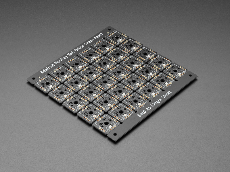
Adafruit Learning System
The easiest way to create custom ortholinear key matrices!
You'll have to modify the definitions to match your setup though
lean prism
Is there a Tessin for 7 as First in? Just asking. Will do its that way for Testing now
livid osprey
A what? Sorry, I'm not sure what you're asking
livid osprey
Oh, I took it from the sample code in the example above
You can change it to any pin you want
I don't even know which Arduino you're using anyways haha
lean prism
Its a micro
So loading the sample onto micro and connect as you posted above should light them up?
The example tells Define rows and columns and I just have one row for testing
But eather way. No lights at all on matter what I do
livid osprey
You'll have to modify the row/col pin parameters and definitions for it to compile properly. The code is written for a feather RP2040, so some of the pins used don't exist on the Arduino micro.
You have VIN and GND connected?
Oh, the sample code only lights up when you have the key pressed
lean prism
I only get light on if i connect ground and out
Also no funtcion if Pressing keys too
I am lost 😩
livid osprey
You can go to the setup() function and change the line lit[i] = false; in the for loop to lit[i] = true;
If you haven't connected the keyboard matrix, the keys won't do anything yet
Do you get any compile errors?
lean prism
So the sample needs to get modifed more then just write the correct Pins for it?
livid osprey
Well, only if you didn't already connect your matrix
If you did, and you updated the pins accordingly, you should get lights...?
Oh, actually, there might be one more correction...
the line keynum = row * COLS + (5 - col); should be keynum = row * COLS + (COLS - col); i think
lean prism
I connected my neokeys as shown in picture and made the Right pins. I did. not put keys an all of them for testing. And i did. not change anything with keys in that code. I only will use 20 keys and not 30
livid osprey
Yeah, you absolutely need to change the ROWS and COLS definitions, as well as the rowPins and colPins
Other than that, as long as the code compiles, you should be able to get SOMETHING...?
lean prism
No Problems with that but no lights
lean prism
All i would like to have for now is to check if they can just light up all at the Same time to check if wiring is correct
But the code could be the wrong for it or not?
The example code i mean
livid osprey
try File > Examples > Adafruit NeoPixel > simple for a simpler neopixel sample code
Just update the PIN and NUMPIXELS definitions.
 livid osprey
Are all of the RED wires connected to VIN? I thought VIN was the hole on the left on the top side.
lean prism
Well all of them are connected to another Pin on the Arduino Right now
livid osprey
I don't think the other pins drive enough current to power a neopixel.
lean prism
The right one is defined in the Code
livid osprey
Correction, they can, but they probably shouldn't be used that way.
lean prism
The other not
livid osprey
Did you connect the VIN pins? They're the only ones that matter for lights.
lean prism
Yeah think I should
livid osprey
Well, not the only one, I should rephrase.
If you don't connect VIN to the arduino's 5V pin, you won't get any light
lean prism
livid osprey
Did you connect the VIN pins? They're the only ones that matter for lights.
I could connect vin from other neokeys to vin from First Pin and all should light up
livid osprey
As long as they all tie back to the Arduino's 5V, you should get some light.
lean prism
And yes they do of corse but that is not the way it showed in the tutorial with the neokey 5x6 ortho
livid osprey
Yes, because they wired it assuming you didn't snap the board apart yet haha
If you snap it apart, you have to make the other connections.
lean prism
I thought that too but:
livid osprey
The VINs are connected internally in the board's snaps, but without them, you have to connect them all together yourself
lean prism
Yes i did. with the ones underneath in the rows
But the ones on top go into different pins in Arduino
Oh
livid osprey
There is no VIN pin on the sides.
livid osprey
You should connect the GND pins together, that is correct
lean prism
And Made row in and gnd
livid osprey
But you need to make sure you have all the pins you need haha
lean prism
Ok so they all had no power
🙈
And that little thing Made me kill 2 Picos and wasted hard time of my life haha
livid osprey
Alright, I gotta go prepare for a meeting
livid osprey
Hope the rest goes smoothly now haha
lean prism
Hope too thanks a lot
lean prism
Ok. I still dont get it to work. No matter what I do. Maybe I soldert to much by now and damaged some of the Neokeys. But I dont want to give up. Therefor I would need a little help of how to wire up this matrix. I made a little matrix and maybe someone has a little time to show me, what pins need to be connected in correct way. That would be very helpfull for me to find out my mistakes.

I only can get the first one light up. No other. No matter if I connect them or not. No matter if using a new one or connect other ways... I am really lost with that . just connecting the Vin to each other did not help eather
brazen falcon
Believe this should be correct.
 lean prism
I will Check that later. Thank you very much
livid osprey
brazen falcon
Believe this should be correct.
@lean prism Be careful of the direction of the arrows. For the keys with the arrows as pictured, the purple lines should actually look like this:
 livid osprey
Not all of the keys have the same direction, so if you're really not confident you can also just avoid using the let and right side data lines entirely.

Thankfully, the top and bottom connections are consistent throughout.
lean prism
Ok just go for in and out like another snake
The vin any Suggestion of get them nicely together too?
livid osprey
Both of the VIN connections on each key are on the same bus, so technically you could simply ensure that all the VINs are connected to one another.
However, in practice, 5V neopixel strips see voltage drops further down in longer strips, so you may want to use thicker-gauge wire if you plan to just daisy-chain them all together across a single path.
For 20 keys, you can probably get away with 22/24AWG wire and a VIN to Arduino connection on both ends.
I forget how many pixels the recommendation is to reinject a voltage source for strips...
lean prism
Oh ok 22/24 awg i Need to Google this
I ordered dupont wire Male to gemalt in Order to wire easier
Maybe now Not big enough
lean prism
They will just not light up that much right?
livid osprey
Some keys might be a bit dimmer than others, but they should all light up regardless
lean prism

ok
This picture just mirrored the 2 at the bottom so sure, the col and vin are other side
livid osprey
With only 20 keys, I don't think the voltage will drop enough to turn the lights off completely. If the last key is too dim, you can try connecting the last VIN back to the Arduino as well and see what happens then.
livid osprey
If you're using exclusively the top and bottom O and I connections, the arrows shouldn't matter to you anymore.
livid osprey
Cleaner wiring?
Not that the primary intent was to snap all the keys apart, but they included it for whomever's use case.
Though following the arrows can help shorten the wires a lot if you do zig-zag
lean prism
Ok i understand i really Love this System its very Smart and Perfect for my use
livid osprey
It removes the need for the long wires at the end of each column
 maiden pilot
Hey guys! I'm running arduino on an esp32, it uses a Adafruit BNO055 sensor to send position data wirelessly over UPD. I'm hoping to figure out how to put the esp in to sleep mode when the IMU doesn't detect motion for X seconds. I'm not even sure where to start with this. Is it possible for the ESP to be "listening" for updated values while in sleep mode?
livid osprey
maiden pilot
Hey guys! I'm running arduino on an esp32, it uses a Adafruit BNO055 sensor to s...
Not wirelessly, to my knowledge. Wake up sources from deep sleep are limited to a few options, including timer, touch, and external GPIO signals. The ULP coprocessor can also handle wake-up triggers, but all the wireless radios are disabled in sleep mode.
maiden pilot
Oh, no I'm not hoping to send a sleep signal to it wirelessly
the BNO055 is wired directly to the ESP32
I just need to figure out how to set the BNO055 to wake the ESP32 over GPIO
livid osprey
I referenced this guide while I was playing with it, you can scroll through it to learn more about deep sleep and Arduino. https://randomnerdtutorials.com/esp32-deep-sleep-arduino-ide-wake-up-sources/
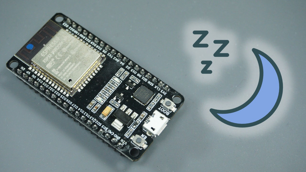
Complete guide for the ESP32 Deep Sleep mode with Arduino IDE and different wake up sources: timer wake up, touch wake up, and external wake up (with examples).
maiden pilot
great! thanks
 daring tide
I am trying to do a project with the nRF52840 Feather board, but I can't compile even a simple test program. I updated the bootloader, deleted all old files and fresh installed the arduino IDE, tried different versions of the board library, but they all gave me different errors compiling. Here is the error I get on the latest version 1.1.0
```c:/users/evelyn/appdata/local/arduino15/packages/adafruit/tools/arm-none-eabi-gcc/9-2019q4/bin/../lib/gcc/arm-none-eabi/9.2.1/../../../../arm-none-eabi/bin/ld.exe: sketch\sketch_nov01a.ino.cpp.o: in function setup': C:\Users\Evelyn\Documents\Arduino\sketch_nov01a/sketch_nov01a.ino:16: undefined reference to Adafruit_USBD_CDC::begin(unsigned long)'
c:/users/evelyn/appdata/local/arduino15/packages/adafruit/tools/arm-none-eabi-gcc/9-2019q4/bin/../lib/gcc/arm-none-eabi/9.2.1/../../../../arm-none-eabi/bin/ld.exe: C:\Users\Evelyn\Documents\Arduino\sketch_nov01a/sketch_nov01a.ino:17: undefined reference to Adafruit_USBD_CDC::operator bool()' c:/users/evelyn/appdata/local/arduino15/packages/adafruit/tools/arm-none-eabi-gcc/9-2019q4/bin/../lib/gcc/arm-none-eabi/9.2.1/../../../../arm-none-eabi/bin/ld.exe: C:\Users\Evelyn\Documents\Arduino\sketch_nov01a/sketch_nov01a.ino:29: undefined reference to Serial'
c:/users/evelyn/appdata/local/arduino15/packages/adafruit/tools/arm-none-eabi-gcc/9-2019q4/bin/../lib/gcc/arm-none-eabi/9.2.1/../../../../arm-none-eabi/bin/ld.exe: sketch\sketch_nov01a.ino.cpp.o: in function loop': C:\Users\Evelyn\Documents\Arduino\sketch_nov01a/sketch_nov01a.ino:78: undefined reference to Serial'
collect2.exe: error: ld returned 1 exit status
exit status 1
Error compiling for board Adafruit Feather nRF52840 Express.
What code are you trying to upload?
daring tide
not even uploading yet, just compiling. it's a simple keyboard matrix test program. heres setup()
void setup() {
    Serial.begin(115200);
    while ( !Serial ) delay(10);   // for nrf52840 with native usb

    for(int x=0; x<rowCount; x++) {
        Serial.print(rows[x]); Serial.println(" as input");
        pinMode(rows[x], INPUT);
    }

    for (int x=0; x<colCount; x++) {
        Serial.print(cols[x]); Serial.println(" as input-pullup");
        pinMode(cols[x], INPUT_PULLUP);
    }

}
oh. i didn't know i needed to #include <bluefruit.h>
livid osprey
Haha, was about to ask you for your #include lines
daring tide
yeah i didn't think i needed to include anything
livid osprey
Hopefully that fixes everything.
daring tide
yep it uploaded just fine
daring tide
it worked fine for a while, but now i can't upload.
when i try to upload after a normal boot (was working fine):
Failed to upgrade target. Error is: Serial port could not be opened on COM8. Reason: could not open port 'COM8': FileNotFoundError(2, 'The system cannot find the file specified.', None, 2)
Traceback (most recent call last):
  File "dfu\dfu_transport_serial.py", line 113, in open
  File "serial\serialwin32.py", line 33, in __init__
  File "serial\serialutil.py", line 244, in __init__
  File "serial\serialwin32.py", line 64, in open
serial.serialutil.SerialException: could not open port 'COM8': FileNotFoundError(2, 'The system cannot find the file specified.', None, 2)

During handling of the above exception, another exception occurred:

Traceback (most recent call last):
  File "__main__.py", line 296, in serial
  File "dfu\dfu.py", line 235, in dfu_send_images
  File "dfu\dfu.py", line 157, in _dfu_send_image
  File "dfu\dfu_transport_serial.py", line 115, in open
nordicsemi.exceptions.NordicSemiException: Serial port could not be opened on COM8. Reason: could not open port 'COM8': FileNotFoundError(2, 'The system cannot find the file specified.', None, 2)

Possible causes:
- Selected Bootloader version does not match the one on Bluefruit device.
    Please upgrade the Bootloader or select correct version in Tools->Bootloader.
- Baud rate must be 115200, Flow control must be off.
- Target is not in DFU mode. Ground DFU pin and RESET and release both to enter DFU mode.
when i try to upload in DFU mode:
    at cc.arduino.packages.uploaders.SerialUploader.uploadUsingPreferences(SerialUploader.java:152)
    at cc.arduino.UploaderUtils.upload(UploaderUtils.java:77)
    at processing.app.SketchController.upload(SketchController.java:732)
    at processing.app.SketchController.exportApplet(SketchController.java:703)
    at processing.app.Editor$UploadHandler.run(Editor.java:2061)
    at java.lang.Thread.run(Thread.java:748)
Caused by: processing.app.SerialException: Error touching serial port 'COM9'.
    at processing.app.Serial.touchForCDCReset(Serial.java:107)
    at cc.arduino.packages.uploaders.SerialUploader.uploadUsingPreferences(SerialUploader.java:136)
    ... 5 more
Caused by: jssc.SerialPortException: Port name - COM9; Method name - openPort(); Exception type - Port busy.
    at jssc.SerialPort.openPort(SerialPort.java:164)
    at processing.app.Serial.touchForCDCReset(Serial.java:101)
    ... 6 more
i had changed the baud rate in Serial.begin to 9600, would that have affected it? and if so, how can I fix this? can something so simple completely brick the board?
of course it randomly decides to work now
but i just keep getting that port busy message all the time
resetting sometimes fixes it
like i can't even open the serial monitor, it just says port busy
solemn cliff
could something be still running that is using it, or could the port have changed ?
daring tide
it was working okay 10 minutes ago. i would have to reset it once each time i uploaded to get the serial monitor up, but it was consistent with that. but now, it isn't working at all. i haven't opened any new programs since then, and i have had device manager open to check the port and it is correct
if its the wrong port it is a different error message than port busy anyway
the device boots up and runs the program, so it gets past the while ( !Serial ) delay(10); // for nrf52840 with native usb line
daring tide
i've never been more frustrated at a project honestly
its so inconsistent
for the price of this board i expect at least the basic functionality to work more than 10% of the time
north stream
It's not the board, but that your computer is allocating a different port every time the board enumerates.
daring tide
north stream
It's not the board, but that your computer is allocating a different port every ...
nope. its always com8 when turned on, switches to com9 when it reboots into dfu from normal boot (happens when uploading when not in dfu mode), and always com10 when i manually put it into dfu
the process is always the same and sometimes works fine. i keep an eye on the com ports while it happens
it seems like the process when uploading during a normal boot is this
on COM8, send command to reboot into DFU as COM9
switch to COM9, flash firmware
switch back to COM8 for normal serial communication
that process was working consistently for me until it wasn't
and again, i can manually enter DFU and switch to COM10 but most of the time it will say port busy when I do that and I have to manually enter DFU at least 2 or 3 more times before it works
huh, looks like having cura running at the same time might have been interfering
daring tide
yeah, i was 3d printing parts for this so i had it open
solemn cliff
you gotta disable the USB plugin in cura if you don't need it
it hogs the serial ports
daring tide
thanks, i'll do that now
solemn cliff
"Marketplace" -> "Installed" tab and uncheck "USB Printing".
daring tide
got it, i use octoprint anyway
solemn cliff
same, cura was spitting M105 (report temperature) all over my REPL
daring tide
oof. well that definitely fixed it, thanks!
lean prism
@livid osprey the in and out just follow the arrows Right?
The pictures yesterday are little confusing because I will connect just like it is on the Board

And i will connect everything First before snapping appart this time
And does vin needs to follow a special way too or is this ok? Missed one line on the bottom left
 brazen falcon
If they're snapped apart totally, I think either neopixel DO can be connected to either of the next one's DI. The arrows are just to show the path if its left intact.
lean prism
livid osprey
Not all of the keys have the same direction, so if you're really not confident y...
not sure because of the info from Hem given here
livid osprey
Yes, the arrows are there to help indicate which side is do and which side is di
Once they’re all snapped apart and mixed up, it’s be hard to tell otherwise
lean prism
ok. And what about the way of VIN?
livid osprey
Any way is fine.
lean prism
thanks. again 🙈
brazen falcon
the signals for the neopixels are routed through the snapapart sections only in the directions of the arrows if you leave them intact.
 stray forge
Can the MusicMaker be used with the PulseSensor?
 lean prism
I think I have wired everything to where it belongs to. Am I right that in Order to get the Ortho 5x6 Demo function correctly, I have to snap it apart now? @livid osprey
 lean prism
It looks like i am missing a connection 🤔 dont get it

I used the simple Test from your help.
solemn cliff
lean prism
It looks like i am missing a connection 🤔 dont get it
it looks like the GND on your rows are not connected to the common GND, they are just connected between the row keys ?
lean prism
Is there a way to tell a single Key a special color and the color has to change in another after push?
oh maybe the wrong chat? I will try in makecode
 autumn timber
Hello I'm using an Arduino Mega 2560 and a fingerprint sensor AS608 and I'm using the Adafruit Fingerprint Sensor Library, the sensor is recognized (the light turns on) but when I upload it it says "Did not find fingerprint sensor" I was wondering if somenone has any tips!
leaden walrus
the light is probably just coming on with power
which fingerprint sensor is it? link to product page?
livid osprey
lean prism
Is there a way to tell a single Key a special color and the color has to change ...
Yes, you can write whatever code you want to change the behaviors of the lights.
leaden walrus
Not all pins on the Mega and Mega 2560 support change interrupts, so only the following can be used for RX: 10, 11, 12, 13, 14, 15, 50, 51, 52, 53, A8 (62), A9 (63), A10 (64), A11 (65), A12 (66), A13 (67), A14 (68), A15 (69).
if using software serial, also need to check pins being used
autumn timber
leaden walrus
the light is probably just coming on with power

DollaTek Módulo de Sensor de Lector de Huella Digital óptico de luz Azul para Arduino Mega2560 UNO R3
leaden walrus
how are you connected to the mega? which wires to which pins?
autumn timber
Red Wire to 5V - GND to GND - White Wire (RX) to 10 and Yellow Wire (TX) to 42
lean prism
livid osprey
Yes, you can write whatever code you want to change the behaviors of the lights.
ok. Thats good. But where do I get this codes from and how do I know how to use them?
I just need it the way
explained above
leaden walrus
@autumn timber what does your SoftwareSerial mySerial(?, ?); line look like?
try:
RED (V+) to Mega 5V
YELLOW (TX) to Mega 10
WHITE (RX) to Mega 42
BLANK (GND) to Mega GND
with:
SoftwareSerial mySerial(10, 42);
Didn't work
livid osprey
lean prism
ok. Thats good. But where do I get this codes from and how do I know how to use ...
https://learn.adafruit.com/adafruit-neokey-5x6-ortho-snap-apart/arduino has basically all of the bits of code needed to get something like that working, but it will need some rearranging for it to match what you're looking for.
Adafruit Learning System
The easiest way to create custom ortholinear key matrices!
leaden walrus
@autumn timber try different baudrates?
also, maybe not a 5V device?

the adafruit library also may just not work with that model
lean prism
livid osprey
https://learn.adafruit.com/adafruit-neokey-5x6-ortho-snap-apart/arduino has basi...
thanks. The Example Code just dont get me to the Hint I maybe need in order to understand what I have to write the code correctly. Is there maybe a little hint I could use? The rearranging is way way more I do understand :/
autumn timber
@leaden walrus ok, I will try that
 crystal vapor
Adafruit SPI Flash library use with itsy nRF52840
Hi!
Is there any reason not to use the Adafruit SPI Flash and SdFat (Adafruit fork) libraries with the itsy express nrf52840 board?
The sd_FAT Format sketch compiles fine with itsybitsy nrf52840 express board selected.
The guide I am using is for a Feather m0 board: https://learn.adafruit.com/adafruit-feather-m0-express-designed-for-circuit-python-circuitpython/using-spi-flash

Adafruit Learning System
Get running faster than ever with the first Adafruit Express board
autumn timber
@leaden walrus what do you think I should change?
 leaden walrus
@autumn timber finger.begin(57600); <-- try different baudrates there
autumn timber
@leaden walrus nothing
leaden walrus
could be a different sensor than the library supports
lean prism
I tryed the Neokey Ortho Demo again and basicly changed the values you mentioned earlyer in here. But there is no function at all. Seems like the Keys not working? How do I activate them? The Neopixel Demos work just fine
 lean prism
it copy the sketch but this errors occure:
Arduino\libraries\Adafruit_Keypad/Adafruit_Keypad_Ringbuffer.h:57:5: note: type 'struct Adafruit_Keypad_Ringbuffer' should match type 'struct Adafruit_Keypad_Ringbuffer'
Adafruit_Keypad_Ringbuffer;
Arduino\libraries\Adafruit_Keypad\Adafruit_Keypad_Ringbuffer.h:57:5: note: the incompatible type is defined here
Adafruit_Keypad_Ringbuffer;

 crystal fossil
Hey folks, I am having some trouble controlling the nixie tube clock that I have been building. I have been working on a simple library for it, but whenever I open the serial monitor in this simple example, tons of lines which I do not understand are printed. They appear on the same baud frequency as the upload speed, rather than what was set in my code, which I do not get. I turned off autoscroll but with it on it is continually printing this. Has anyone seen this before? What may be causing this? I am using the Feather Huzzah32 (ESP32) board. I will post a screenshot of the code and paste the library code below.

Pastebin
Pastebin.com is the number one paste tool since 2002. Pastebin is a website where you can store text online for a set period of time.
Please note that I have just recently started with this and am doing this as a means of learning Arduino and coding in general. If I have made a stupid mistake or seem to not understand something, please help correct it. Thank you.
cedar mountain
crystal fossil
Hey folks, I am having some trouble controlling the nixie tube clock that I have...
Check the "core debug level" setting in the Tools menu. It's probably been set to a level which enables extra diagnostic messages like that. You probably want "none" instead.
crystal fossil
cedar mountain
Check the "core debug level" setting in the Tools menu. It's probably been set t...
Thank you. I will try this now.
I am now getting a new message:
 cedar mountain
crystal fossil
I am now getting a new message:
cedar mountain
crystal fossil
I am now getting a new message:
That seems to indicate a watchdog timer reset ("WDT"), which might happen if your code crashed or locked in an infinite loop.
crystal fossil
Ok. Thank you for your help. I will fiddle around with this some more later on and try to see what is causing it. Have a nice day
 formal onyx
I want to use a bluetooth module with my arduino nano, I've used it with an uno, and know that I shouldn't connect it to pins 0/1 because it interferes with uploading. On the uno, I believe I used alternately 11/12 or 12/13, I know some pins work but not all, which pins can I use for the arduino nano?
cedar mountain
formal onyx
I want to use a bluetooth module with my arduino nano, I've used it with an uno,...
Both the Nano and the Uno have only one hardware serial port, but if you use a software-serial library, you should be able to use almost any I/O pin.
lean prism
@leaden walrus hello. I have problems using the Sample Sketch Adafruit Keypad\Ortho 5x6Demo. I get this Error:
C:\Users\nosfe\Documents\Arduino\libraries\Adafruit_Keypad/Adafruit_Keypad_Ringbuffer.h:57:5: note: type 'struct Adafruit_Keypad_Ringbuffer' should match type 'struct Adafruit_Keypad_Ringbuffer'
Adafruit_Keypad_Ringbuffer;
^
C:\Users\nosfe\Documents\Arduino\libraries\Adafruit_Keypad\Adafruit_Keypad_Ringbuffer.h:57:5: note: the incompatible type is defined here
Adafruit_Keypad_Ringbuffer;
^
I write you because I found only related to something like this on Github: https://github.com/adafruit/Adafruit_Keypad/issues/6

GitHub
Hi. This is the error message on adafruit keypad library testing keypad_test arduino sketch. Arduino:1.8.9 (Windows Store 1.8.21.0) (Windows 10), Tarjeta:"Arduino Due (Programming Port)&am...
Any idea what I can do about this?
 cold lagoon
im trying to brogramm an Rotary encoder but it keeps giving me 0 and -1 if i rotate it
 charred sun
Has anybody been able to successfully set up / Upload code via the Arduino IDE on a macintosh for the LED glasses that came in the latest Adabox (20)? I get an obscure python error that I can't decipher and can't upload the demo code. Circuit Python stuff works fine.
 spark harness
i have the SSD1306 OLED Display, how can i make it so that it displays things (like a bitmap for example) in more than 1 color?
cedar mountain
spark harness
i have the SSD1306 OLED Display, how can i make it so that it displays things (l...
If it's a monochrome display, that won't be possible.
cedar mountain
Can you link to the product page for the one you have? The SSD1306 just specifies the driver chip, not the display panel.
spark harness
oh nvm its just white text
leaden walrus
@lean prism can open a new issue, be sure to specify what hardware platform you are building for
lean prism
I am on Windows 10 and use arduino micro. @leaden walrus
crystal vapor
crystal vapor
Adafruit SPI Flash library use with itsy nRF52840
Hi!
Is there any reason not t...
Answering my own questuon after simply giving it a go - works great with nRF52840 express 🙂
 paper mist
hi guys, i'm trying to use the fontconvert tool included with the adafruit gfx library however i'm running into an issue when building it that ft2build.h was not found. i have freetype2 package installed (i'm on arch linux) and the package does show under /usr/include so i'm not sure what is causing this error. maybe ft2build is an outdated name or something? any help is appreciated, thanks 🙂
never mind, i'm an idiot, was building manually with gcc instead of using the makefile 
pine bramble
;)
pico-sdk seems to leverage the OS quite a bit. I installed arm-none-eabi-gcc (whatever that sequence is) to satisfy a dependency and it works just fine.
So I mean it liked the Debian package for that version of gcc.
Usually, they fully support Linux in these kinds of things.
 fiery verge
Hi all, I was wondering if anyone can point me to the definition of Arduino pins to microcontroller ports for the SAMD51. For example, on https://learn.adafruit.com/adafruit-matrixportal-m4/pinouts, it notes the board.ESP_RESET is Arduino pin 30. Is there a way for us mortals to find that mapping? I have a few other pins on that design that I know the port number (e.g. PA12 and PA13) but I need the Arduino pins to use them in PlatformIO
north stream
fiery verge
Hi all, I was wondering if anyone can point me to the definition of Arduino pins...
Yes, you can look at the same files the Arduino IDE uses to describe that mapping. Where the files are varies somewhat with which environment you're using, but on MacOS, the file for the that board is in my home directory, in Library/Arduino15/packages/adafruit/hardware/samd/1.6.5/variants/matrixportal_m4
So boards in general go in the Library folder in Arduino15/packages, then there are subdirectories for the various vendors. Under that, the boards are under "hardware", then sorted by architecture (the M4 is a SAMD), then version.
vivid rock
on windows, it is in
C:\Users\<username>\AppData\Local\Arduino15\packages\adafruit\hardware\1.6.5\variants
Note that normally folder AppData is hidden from view, as most users do not need to know of its existence (or at least, so Microsoft thinks), so you need to turn on option View->Hidden items in the file browser
Or you can look it up in the github repo: https://github.com/adafruit/ArduinoCore-samd/tree/master/variants/matrixportal_m4

GitHub
Contribute to adafruit/ArduinoCore-samd development by creating an account on GitHub.
fiery verge
@north stream / @vivid rock thanks for the tip! That is exactly what I was looking for. I didnt realize all the pins I needed already had #defines in those files so Im all set!
 viscid snow
Hey everyone,
I am having problems controlling a stepper motor using my Arduino Nano. The code I'm trying to use is found here: https://atlantisq.wordpress.com/portfolio/obj-2601-barn-door-tracker-astra-v2-1/
I can't seem to make the stepper turn, however other sketches do make it turn. I don't fully understand the code provided so I don't know how to troubleshoot
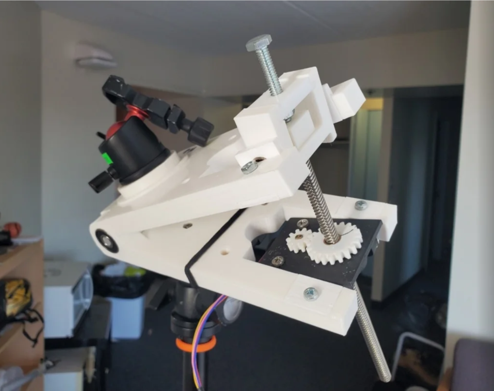
Astra is a barn door tracker for astrophotography. It uses a straight leadscrew drive and can be driven by a 5V USB power source. An Arduino is used to control the speed of the leadscrew in order t…
livid osprey
viscid snow
Hey everyone,
I am having problems controlling a stepper motor using my Arduino...
What other sketches are you using?
viscid snow
livid osprey
What other sketches are you using?
https://www.instructables.com/BYJ48-Stepper-Motor/ This sketch does make the stepper turn

Instructables
BYJ48 Stepper Motor: Stepper Motor is a motor controlled by a series of electromagnetic coils. The center shaft has a series of magnets mounted on it, and the coils surrounding the shaft are alternately given current or not, creating magnetic fields which repulse …
livid osprey
MIght be a problem with the stepper.h library, since the other example seems to have hard-coded its own stepper motion. Do you get any errors in your serial output?
viscid snow
are you referring to the example that is working when you're talking about the "other example"?
livid osprey
Yes
viscid snow
Yeah, It has the weird use of cases
I do not seem to get any errors, uploads work fine and the serial output is as expected, allthough it goes very fast
when I do turn off the comments, that is
A video showing the problem and my driver board
livid osprey
not sure why your step states are alternating like that, there's no way your stepper would turn if that's the sequence it's following.
viscid snow
That's what I was thinking, but I'm not sure what part of the code makes it behave like this
livid osprey
Try changing the steps in the while loop from 2 to 1?
viscid snow
so like this?
  stepper.step(1);
steps=steps+1;```Try that. If it doesn't work, you can also play with the speed setting.
livid osprey
Should at least turn now. My guess is the stepper library defaults to 4 steps per cycle instead of 8...
viscid snow
livid osprey
Try that. If it doesn't work, you can also play with the speed setting.
The speed is very important though, because it is supposedly programmed in such a way that the speed makes the contraption track with the rotation of earth
livid osprey
Yeah, you might have to do some adjustment somewhere else.
I can't speak for the motor math the original author did, but the difference between the motor turning and not makes me think that this is the original desired behavior the author wanted when he set the steps to move by two at a time.
viscid snow
right
livid osprey
I would just use it as is, while being aware that the math may or may not be off due to the change you had to make to get it to work in the first place.
viscid snow
the '2' would point to the amount of steps the original author would want it to take
livid osprey
Probably a difference in assumed default behavior.
Test it and see if the speed matches, I guess.
viscid snow
Which is confusing me, because i'm using the exact same hardware haha
Hm I'll try it some more
thanks anyways!
 nova comet
Hey everyone. I’ve been trying to create a program that essentially generates a PWM pulse on the rising edge of one of my IO. However, I have very tight time constraints so I found that using analogWrite for generating pwm was a little slow.
I resorted to polling the channels who’s rising edges i care about and basically just toggle the output high and low with the calculated period. The problem now is that the delay function isnt very accurate at low uS values and also seems to have some overhead. Yielding slightly off duty cycles.
I was hoping for help on this. Perhaps help writing a function that generates a PWM signal given a specific frequency and duty cycle.
I can send code if that helps
cedar mountain
Generally you'd probably want to make use of a timer peripheral on the microcontroller, but the details of that will depend on the chip you're running on.
nova comet
Im using a seeeduino xiao, samd21 mcu
I tried writing some stuff with timers but i dont have a ton of experience with it
cedar mountain
Cool, that's a nice modern chip which should have a pretty capable timer.
nova comet
Any resources that might help me get going?
I have three 120hz signals that come in one after the other, with a little dead time between. Ill have to change duty cycle and frequency at each rising edge
cedar mountain
Not off the top of my head, I'm afraid. I'd just be doing the same Google searches you would. 😉
nova comet
Fair enough
 green heath
#define rs 12
#define rw 11
#define en 10
#define d4 9
#define d5 8
#define d6 7
#define d7 6
#define contrast 0

#define left 13
#define right 12
#define pot


LiquidCrystal lcd(rs,rw, en, d4, d5, d6, d7);

void setup() {
  //analogWrite(5,contrast);
  // set up the LCD's number of columns and rows:
  lcd.begin(16, 2);
  // Print a message to the LCD.
  lcd.print("hello, world!");

  pinMode(left, INPUT_PULLUP);
  pinMode(right, INPUT_PULLUP);
  pinMode(5, OUTPUT);
  digitalWrite(5, LOW);

}

void loop()
{
  int state = 0;


  //lcd.print("hello");

  //while(true)
  {
    delay(1000);
    lcd.clear();

    if(digitalRead(left))
    {
      lcd.setCursor(0, 1);
      lcd.print("turning left");
      state = 0;
    }
    else if(digitalRead(right))
    {
      lcd.setCursor(0, 1);
      lcd.print("turning right");
      state = 1;
    }
    //else if(!digitalRead(right) && !digitalRead(left))  state = 2;
    else state = 99;
    switch(state)
    {
      case 0:


      //todo set stepper direction left
      //todo set speed
      break;

      case 1:


      //todo set stepper direction right
      //todo set speed
      break;

      case 2:
      //lcd.setCursor(0, 0);
      //lcd.print("following mode");

      //todo set stepper direction right
      //todo follow pot
      break;
      case 99:
      //lcd.setCursor(0, 0);
      //lcd.print("idle");
      break;
    }
  }
}
oops, oh well, my code is printing random characters on the LCD screen. any idea what this is causing?
the only thing I found was that I couldnt use pwm for the contrast and that would possibly be the cause. and that I should use a pot. but I dont have a pot and not much room on my perfboard for a voltage divider and hoped putting it on a pin would do the trick
leaden walrus
which LCD?
green heath
1602A
leaden walrus
does "hello, world!" show up?
green heath
the hello world example works fine
I am trying the set cursor example right now
it does show up on startup as well. then it adds random characters
leaden walrus
are left/right wired to buttons?
leaden walrus
so high/true will be not pressed
leaden walrus
    if(digitalRead(left))
    {
      lcd.setCursor(0, 1);
      lcd.print("turning left");
      state = 0;
    }
you want that to happen when the button is pressed?
green heath
yes
green heath
I think I found a different issue, I miscounted the ports. 12 is already used for the LCD, and overwritten for the one of the buttons
leaden walrus
cool!
green heath
another question, is the arduino IDE smart enough to decide what size of integer to assign. eg should i use int or should I use fixed width integers?
leaden walrus
int will be different sizes on different boards:
https://www.arduino.cc/reference/en/language/variables/data-types/int/
if you want known fixed size, use the stdint defs, like uint8_t
green heath
thank you!
another question, can the IDE compile C code? I have an AVR stepper library I would like to use
 fresh token


I have a CAP1188 that will not communicate at all- no lights will light up when I touch the respective capacitive inputs
Any ideas?
this is default code

nevermind, forgot I melted a hole in the breadboard there 🧠
north stream
green heath
another question, can the IDE compile C code? I have an AVR stepper library I wo...
Yes, Arduino uses Wiring, which is a dialect of C++, which is in turn a superset of C.
native dagger
I assume arduino is capable of taking advantage of the 2 cores in an RP2040?
 broken viper
Yes, I think so
 ocean sundial
Hi everyone! I have a little project I'm working on using a Nano plus an MPU6050, BMP280 and an HMC5883. I'd like to log the data from these sensors and be able to access it on my computer after each run. However, I'd like to do this with a flash memory. I was hoping you guys could help me with this as I've never worked with flash memory before using Arduino and the greatest challenge I've found is getting the data from flash.
The common solution here is an SD Module, however, the modules I've found so far are too big for the 4x6cm form factor I'm using and I want to (1) stay within that form factor and (2) use a module that is high-vibration tolerant - so an SD Module is probably a no-go (unless you know of any modules small enough). I have found two breakout boards that might work for my project. There's the W25Q64 64Mbit 8MByte Flash Storage Module and Adafruit's XTSD 512 MB breakout boards. I'm heavily inclined towards the XTSD given its greater memory storage despite being bigger than the W25Q64 module. What I don't know is how to get the logged data from either module (if that's even possible).
- Is it possible to 'dump' flash via the Nano's USB port onto the serial monitor? or
- Maybe add some male header pins to my project and connect an SD Module with an SD card and 'dump' flash onto that external module (after each run)?
- Do you think the 328 MCU on the Nano would struggle with this?
I haven't bought neither the XTSD nor the W25Q64 modules because I want to pick one first. Apologies for the newbie questions but I'd appreciate any info, resources or help with this. Thank you!
vivid rock
SdFat and TinyUSB libraries allow one to access filesystem on a flash memory chip and even make it accessible to the computer as if it were a removable USB memory stick
however, not all boards are supported - those based on m0/m4/esp32-s2(note s2!) work, many others don't
maybe instead of nano, use something like itsy bitsy m4?
 minor flax
Man I'm losing my mind with the caterina bootloader. What a total nightmare.
ocean sundial
vivid rock
SdFat and TinyUSB libraries allow one to access filesystem on a flash memory chi...
Thank you so much for your response! I'll check out those libraries and the suggestions you made. The bitsy m4 is definitely worth considering switching to. Thank you!
pine bramble
i have a Adafruit Bluefruit LE UART Friend, and i would like to change it's bluetooth name. is that possible?
pine bramble
looks like i should use : AT+GAPDEVNAME
but i don't know how to pull the existing name and do a string comparison...
 stable forge
pine bramble
looks like i should use : AT+GAPDEVNAME
pine bramble
stable forge
https://learn.adafruit.com/introducing-adafruit-ble-bluetooth-low-energy-friend?...
stable forge
pine bramble
looks like i should use : AT+GAPDEVNAME
pine bramble
stable forge
https://learn.adafruit.com/introducing-adafruit-ble-bluetooth-low-energy-friend?...
yes but it only gives me the command, not how to pull it as a string and then do a comparision.
stable forge
pine bramble
yes but it only gives me the command, not how to pull it as a string and then do...
If you send the command with no args, then you will get back the name on the UART connection and can read it.
pine bramble
yes. but how do the string comparision in arduino
leaden walrus
there are several ways:
https://www.arduino.cc/reference/en/language/variables/data-types/stringobject/
can just try == as a first pass. with some trim also
 willow compass
new to this whole Arduino and Adafruit stuff (thrown onto a school project). Currently have an Arduino Mega, and an Adafruit ultimate gps. I am simply trying to parse the gps data that is coming in, but having many problems. The only time I can get any data off of the GPS is if I have the gps plugged into RX and TX (pins 0 and 1), and a blank sketch uploaded into the Arduino. My issue is that I need to get the data to work with TX2 and RX2. I was trying literally any of he available testing code that is given in the library such as the Hardware Serial echo test. But nothing I have tired has worked. not even something as simple as the following code is giving me anything. Serial2.available() is always reading as 0.
void setup() {
  // put your setup code here, to run once:
  Serial.begin(115200);
  Serial2.begin(9600);
}

void loop() {
  // put your main code here, to run repeatedly:
  if(Serial2.available() > 0)
  {
    char c = Serial2.read();
    Serial.print(c);
  }

}
@willow compass GPS shield or breakout?
north stream
I'm not sure which pins are TX2 and RX2, but Serial 2 should be on GPIO pins 16 (TX) and 16 (RX)
cedar mountain
(16 and 17, that is.)
leaden walrus
this one?
https://www.adafruit.com/product/746
willow compass
Yes!
So my team has been working on it for two hours, I had to leave shortly, they have run through dozens of different tests and basic inputs and pins, the most they have been able to read out of it is a -1
Other wise the only time we get data is pins 0 and 1 with a blank sketch, but obviously this isn’t viable
leaden walrus
"shortly" = how long? got some time to work things now?
willow compass
I have time yes
leaden walrus
you're using a mega?
willow compass
Yes
leaden walrus
table here has good summary of serial pins:
https://www.arduino.cc/reference/en/language/functions/communication/serial/
one confusing point may be that there will be two serial instances to consider
one for the Serial Monitor
and one for the GPS
if they aren't already in use, can use the Serial1 pins and follow the hardware serial examples
19(RX) and 18(TX) on the mega
willow compass
Serial 1 is taken
we have Serial 2 and 3
and we have been changing any variables for Serial2 if it uses Serial1
i'm going to try Serial 1 real quick just to see
leaden walrus
if it's taken, then don't worry about it
the others should work just as well
just need to change code
i'm testing here with a mega and the GPS breakout
this works for me:
5V to VIN
GND to GND
16(TX2) to RX
17(RX2) to TX
what code?
leaden walrus
and then use this example:
https://github.com/adafruit/Adafruit_GPS/tree/master/examples/GPS_HardwareSerial_Parsing
and change only one line:
#define GPSSerial Serial2
 leaden walrus
 willow compass
 leaden walrus
hmmm...not getting any sentences
how's your soldering on the breakout? and your wiring connections in general?
willow compass
I would assume fine, but I am not the one who was involved with that, our project instructor has been creating our wires and such for us
leaden walrus
at this point, checking the hardware setup would be the best next step
if you can post a photo here, can take a look
or posting in the forums is another option
willow compass
 leaden walrus
thanks. and disconnect the wires. want to check the header pins on the breakout.

 leaden walrus
thanks. soldering looks fine.
are the red/black/white/blue wires going directly to the mega?
willow compass
Yes
leaden walrus
they're female/male jumpers, so going directly into mega headers?
willow compass

 willow compass
yes
willow compass
white is RX from GPS, and blue is TX from GPS
leaden walrus
16(TX2) to RX
17(RX2) to TX
 leaden walrus
cool. it's working now.
that's the general output you'll see until it gets a lock
then there will be more info
willow compass
alright, i'll have to do that later as the wheels are off of this thing
but thank you for the help
leaden walrus
np. looks like a common TX/RX connection confusion. happens all the time.
in general, you want:
TX <-> RX
RX <-> TX
bruh, instructor told us the opposite
leaden walrus
it's a confusing topic
there are other protocols where you do match pin-to-pin
like SPI or I2C
willow compass
makes, sense, we have that with other things and it works fine
leaden walrus
a lot of confusion comes from devices that will label their RX pin as TX and their TX pin as RX
just to allow TX<->TX and RX<->RX when making wiring connections
but for others used to the general connection scheme, they will try it the other way, get it wrong, be confused, etc.
willow compass
was about to say, even on the adafruit guide it says tx to tx and rx to rx
but that makes sense
leaden walrus
it's a "fun" issue that we just have to live with. there's no simple solution.
the GPS guide?
 leaden walrus
ugh. so...yet another layer of confusion.
yah, that's for a specific use case.
with the uno
ignore that section of the guide. it doesn't really apply for your use case.
just skip to this section:
https://learn.adafruit.com/adafruit-ultimate-gps/arduino-wiring
and since you have available hardware serial, use that info. ignore the "software serial" info.
GPS RX to Feather TX and GPS TX to Feather RX.
then it's more inline with expected normal wiring
willow compass
Alright
Thank you !
I apologize for added confusion of being confused in general. Was thrown in the deep end on this
leaden walrus
np. and nothing really to apologize for. as simple as serial should be, it can be amazingly confusing.
acoustic sand
Do I need to install something special to mount circuitpython on a Feather M4 Express under Ubuntu on a Raspberry Pi? It shows up under Windows 8.1, but not on a Raspberry Pi running either Ubuntu or Raspbian.
I do have a lot of disks showing up when I run sudo fdisk -l but I've no idea if one of them is my Feather. I'm new to Linux and Adafruit products.
Maybe this is the correct drive?
Units: sectors of 1 * 512 = 512 bytes
Sector size (logical/physical): 512 bytes / 512 bytes
I/O size (minimum/optimal): 512 bytes / 512 bytes
try checking dmesg after plugging it in
you may need to mount it
but if you're running the desktop version, i'd expect it to automount it similar to windows
also. maybe be better in #help-with-circuitpython or #help-with-linux-sbcs
acoustic sand
dmesg gave me pages and pages of text. I'm not sure what I'm looking at, but there are errors.
north stream
248 KiB is a pretty small drive.
leaden walrus
pi@raspberrypi:~ $ dmesg | tail -20
[  255.205776] input: Adafruit Industries LLC QT Py M0 Keyboard as /devices/platform/soc/3f980000.usb/usb1/1-1/1-1.3/1-1.3:1.3/0003:239A:80CC.0001/input/input3
[  255.272282] input: Adafruit Industries LLC QT Py M0 Mouse as /devices/platform/soc/3f980000.usb/usb1/1-1/1-1.3/1-1.3:1.3/0003:239A:80CC.0001/input/input4
[  255.273014] input: Adafruit Industries LLC QT Py M0 Consumer Control as /devices/platform/soc/3f980000.usb/usb1/1-1/1-1.3/1-1.3:1.3/0003:239A:80CC.0001/input/input5
[  255.273477] hid-generic 0003:239A:80CC.0001: input,hidraw0: USB HID v1.11 Keyboard [Adafruit Industries LLC QT Py M0] on usb-3f980000.usb-1.3/input3
[  255.369062] usbcore: registered new interface driver uas
[  255.392328] cdc_acm 1-1.3:1.0: ttyACM0: USB ACM device
[  255.395175] usbcore: registered new interface driver cdc_acm
[  255.395198] cdc_acm: USB Abstract Control Model driver for USB modems and ISDN adapters
[  255.464147] usbcore: registered new interface driver snd-usb-audio
[  256.234785] scsi host0: scsi scan: INQUIRY result too short (5), using 36
[  256.234821] scsi 0:0:0:0: Direct-Access     Adafruit QT Py M0         1.0  PQ: 0 ANSI: 2
[  256.239321] sd 0:0:0:0: [sda] 129 512-byte logical blocks: (66.0 kB/64.5 KiB)
[  256.251402] sd 0:0:0:0: [sda] Write Protect is off
[  256.251434] sd 0:0:0:0: [sda] Mode Sense: 03 00 00 00
[  256.254217] sd 0:0:0:0: [sda] No Caching mode page found
[  256.254247] sd 0:0:0:0: [sda] Assuming drive cache: write through
[  256.278764] sd 0:0:0:0: Attached scsi generic sg0 type 0
[  256.335073]  sda: sda1
[  256.361873] sd 0:0:0:0: [sda] Attached SCSI removable disk
[  256.942732] FAT-fs (sda1): Volume was not properly unmounted. Some data may be corrupt. Please run fsck.
pi@raspberrypi:~ $ ls /media/pi/
CIRCUITPY
that's running latest rasp pi os desktop
after plugging in a QTPY running CP 7
it did automount it under /media/pi
i'm ssh'd in, so not sure what the actual desktop UI does
acoustic sand
I ran mount and I see no /media/pi
leaden walrus
pi@raspberrypi:~ $ mount | grep CIRCUITPY
/dev/sda1 on /media/pi/CIRCUITPY type vfat (rw,nosuid,nodev,relatime,uid=1000,gid=1000,fmask=0022,dmask=0022,codepage=437,iocharset=ascii,shortname=mixed,showexec,utf8,flush,errors=remount-ro,uhelper=udisks2)
so it must be something with the OS version you're running
acoustic sand
Thank you. That at least narrows it down.
I should have mentioned that it mounts fine in boot mode.
I'm going to flash the board and try again. maybe I corrupted something.
leaden walrus
good idea. that can happen for various reasons.
and you'd see same behavior on another machine
even after installing new firmware, you may still get same behavior
neat! only took a minute to get VNC setup.


 faint junco
Hi guys. How loud should my buzzer be for the driver to hear it? I'm trying to make an alert system for a motorcycle, if it's over speeding, it will buzz. So, I'm still on papers so can't really test it
acoustic sand
For posterity's sake, erasing the Feather M4 Express and reinstalling circuitpython worked. It now mounts properly.
north stream
faint junco
Hi guys. How loud should my buzzer be for the driver to hear it? I'm trying to ...
The short answer is "pretty loud". The more accurate answer would depend on how loud the motorcycle is, how loud the surrounding traffic is, the type of helmet the driver is wearing, their hearing acuity, etc.
 fossil fossil
hi ...
this is my Arduino [ESP32 - MPU 6050] project ...
how can i make similar that on Visuino?
thanks a lot. 🙏
green thunder
Does anyone know (or know where I can find out) what the GPIO are for the on-board QSPI flash for the Feather RP2040 (or really any of the Adafruit RP2040 boards)? I'd like to use it in Arduino with the Philhower core but I've had a difficult time finding this information.
 green thunder
Are those the GPIO though? As far as I can tell from the rest of the schematic, those numbers don't necessarily correlate to GPIO 🤔
solemn cliff
I'm not sure what you want to do
green thunder
That's actually a good question lol. What I'd like to do is just use a filesystem of some sort with the built-in flash
I was trying to work backwards from how I usually do it which is to use the Adafruit fork of the SdFat library. However, that doesn't work in the Philhower core, so I thought I'd explore why and how/if I could fix it.
solemn cliff
on the RP2040 these are dedicated pins, due to having no internal flash, the code always runs off the external flash, unlike adafruit's "express" boards where it's separate and not used by arduino by default
green thunder
But, if there's already some other way that works, that will work too lol
solemn cliff
so I don't know how you access the flash as such, but I would assume it's already handled at some level and you don't need to worry about the pins
green thunder
solemn cliff
on the RP2040 these are dedicated pins, due to having no internal flash, the cod...
Right, that makes sense. If I look at the pinout diagram in the learn guide for the Feather M4 Express, it actually does list the GPIO for those though, even though they aren't broken out. Unfortunately, the RP2040 diagram does not do the same.
green thunder
solemn cliff
so I don't know how you access the flash as such, but I would assume it's alread...
I'm looking into this now. It seems like there must be some built-in way in the core to use a file system.
Thanks for trying to help y'all, I really appreciate it 
Got something! It looks like what I'm supposed to do here is use LittleFS instead of the Adafruit SDFat fork. In the Philhower core you can choose how much of the flash you'd like to dedicate to the firmware and how much to the filesystem. I chose the size I wanted to use, and successfully built and ran the SpeedTest example, which performs the basic filesystem operations.
stable forge
green thunder
Are those the GPIO though? As far as I can tell from the rest of the schematic, ...
The QSPI pins are dedicated pins; they are not GPIO pins
green thunder
stable forge
The QSPI pins are dedicated pins; they are not GPIO pins
Understood. Thank you!
stable forge
ah, I see Neradoc said that already
green thunder
I still appreciate it. I was banging my head against this for awhile, and I always appreciate offers to help 🙇
stable forge
I forget to scroll discord when I see a query and hit the reply button 🙂
north stream
Same. 🤦🏾
native dagger
trying to understand some C++ code for shutting down a pi on a button press:
</pre>
<pre>#include <wiringPi.h>
#include <stdio.h>
#include <unistd.h>
#include <linux/reboot.h>

int ioPin = 7; // GPIO04, physical pin 7

int main (void) {
    wiringPiSetup ();
    pinMode (ioPin, INPUT);
    printf("c-watch v0 is now running.\n");
    while(1) {
        pullUpDnControl(ioPin, PUD_DOWN);
        if (!digitalRead(ioPin)) {
            printf("LOW\n");
            break;
        }
        delay(1000);
    }
    printf("Got signal, starting shutdown.\n");
    // Would like to change to dbus at some point
    system("shutdown -P now");
    delay(500);
    return 0;
}</pre>
<pre>
What do the </pre> and <pre> commands do?
native dagger
ahhh ok
leaden walrus
it's commonly used to surround code elements, so that's why it's there in the first place
native dagger
It looked like HTML but I don't know much cpp so I had a confuse
what would be a reason to use C++ over python for this? Speed?
leaden walrus
that'd be a general reason for c++ vs python
native dagger
ok cool
leaden walrus
but in this case, it's not critical, so not really necessary
a python script would work just as well
native dagger
on a pi, where would printf in C++ or print in python go?
leaden walrus
do you mean what are the python equivalents for printf and print ?
native dagger
no sorry, where does the output go
like if I add a bunch of print statements to my code that's running on start on the pi, am I just shouting into the void?
leaden walrus
in both cases, C++ and Python, they'd go to standard out
native dagger
hmm let me google that
leaden walrus
you can end up shouting into the void, if for example you run things a service (sysemd)
native dagger
yeah I'm using systemd
Having an issue with it actually but that's in the other channel
leaden walrus
then you'd want to look into how handling standard out is dealt with
native dagger
ok cool. I don't need to monitor print statements, was just curious
leaden walrus
there's probably a more specific way to log message when using systemd, so it'll show up nice when running systemctl status etc.
but i actually don't know the specific details, i've only done very simple services with systemd
native dagger
No worries, I don't need to log anything. My script that runs on start plays music so it's easy to tell if it's running or not
leaden walrus
yep. and a basic "is it running or not" can be determined without any specific prints.
just the basic output from status will let you know
native dagger
while I have you, do you mind weighing in on my issue in #help-with-linux-sbcs ?
 gilded gazelle
trying to run the selftest on a pyportal-titano
https://github.com/adafruit/Adafruit_Learning_System_Guides/tree/main/PyPortal_Titano_ArduinoSelfTest
and compile fails with
https://pastebin.com/Ej3TtTeA

GitHub
Programs and scripts to display "inline" in Adafruit Learning System guides - Adafruit_Learning_System_Guides/PyPortal_Titano_ArduinoSelfTest at main · adafruit/Adafruit_Learning_...
Pastebin
Pastebin.com is the number one paste tool since 2002. Pastebin is a website where you can store text online for a set period of time.
gilded gazelle
downgraded to wifinina-1.8.0 works now
 quartz anvil
Hi
Could someone help me please?

here plzplzplz
nvm i understood as i drew it xd
 terse summit
Hey guys, I need help with the BNO055 IMU. I have two servos and the IMU on an arduino mega 2560 and I am unable to operate the two servos simultaneously while the IMU is working. The problem seems to be with the line in the main loop:
bno.getEvent(&event);
As soon as this line is uncommented, only one servo works. Any idea what the problem might be? Also, if one of the servo is plugged with the IMU working, it jitters. Using Adafruit_TiCoServo.h solved the jittering, but not the simultaneous servos problem.
I am done working on this for today and will get back at it tomorrow, in the meantime if you have any suggestions it would be greatly appreciated!
my main loop is set at 100Hz, maybe its too fast?
here is the code:
 verbal hill
This is probably a ridiculously simple question, but I'm confirming from the Python world into Arduino by following the guides...
q: is it possible to have a text or ini file or similar on the device that your sketch can read from? My guess is no, after you compile and upload, the board doesnt appear in windows like it did when it was Circuit Python
solemn cliff
verbal hill
This is probably a ridiculously simple question, but I'm confirming from the Pyt...
there's a trick for that, like this project: https://learn.adafruit.com/pyportal-animated-gif-display
it uses Circuitpython to format the external flash as a drive, then overwrites with Arduino code that uses tinyUSB to present the files as a flash drive to the PC
verbal hill
But if it overwrites the Arduino code, then you need to reflash to get your program going?
solemn cliff
first you flash with CP to create the drive, but you do it only once, then you replace with the arduino code, which then accesses the drive
subsequent updates to the arduino code will not erase the drive
verbal hill
hmmm interesting. Im reading through the sample. Im going to have to read it a few times to get this to sink in
I'm coming from the QTPY / NeoKey project (CP wont run this, so I'm here in Arduino) -- simply, my idea was having a text file with 4 lines, a "key" if you will for each line, thus an easy way to customize the macro you want. It sounds like, in theory I should be able to do this with the ardunio code using this hack
vivid rock
verbal hill
This is probably a ridiculously simple question, but I'm confirming from the Pyt...
yes - this is what SdFat library gives you.
You can format the flash as FAT filesystem either using the trick above or using the flash formatter sketch included as example in SdFat library.
In addition, TinyUSB library allows you to access the formatted flash filesystem from a computer as if it were a USB memory stick
verbal hill
Ok, thanks both - I'm making notes here; will giver it a try
 fair sequoia
When using the Adafruit PCA9685 16 channel PWM Servo Driver, how do you map servos to their channels on the board (when using the Ardunio IDE)? I have been looking through this tutorial https://learn.adafruit.com/16-channel-pwm-servo-driver?view=all#using-the-adafruit-library however as far as i can see it doesn't mention it. Any other example code i've looked through only does a sweep of all the channels on the board and never references a single channel. I've been looking all day so any help is greatly appreciated.
cedar mountain
fair sequoia
When using the Adafruit PCA9685 16 channel PWM Servo Driver, how do you map serv...
I'm not sure what you're asking. You specify the channel number that you want to control in the setPWM() function call.
fair sequoia
I get the error that 'setPWM' was not declared in this scope
livid osprey
fair sequoia
When using the Adafruit PCA9685 16 channel PWM Servo Driver, how do you map serv...
fair sequoia
livid osprey
https://adafruit.github.io/Adafruit-PWM-Servo-Driver-Library/html/class_adafruit...
Do I need to include unit8_t ? Also i assume i can leave the rest blank as i don't need it
livid osprey
No, that's just the type the argument expects.
fair sequoia
So all i need is setPWM(0) ?
livid osprey
No, you do need on time and off time as well.
getPWM() is single-argument, but setPWM() must have all three arguments.
cedar mountain
It would probably be fruitful to look at how the function is used in the example code.
fair sequoia
livid osprey
getPWM() is single-argument, but setPWM() must have all three arguments.
Would you say getPWM() is the equivilent of attaching a pin on the Arduino?
fair sequoia
cedar mountain
It would probably be fruitful to look at how the function is used in the example...
Sorry i don't mean to waste your time but i'm new so reading the examples doesn't always help (when i don't understand what it's defining). This link is useful though, thank you
livid osprey
No, getPWM would return the PWM reading of the pin. The equivalent of attachment is done when instantiating Adafruit_PWMServoDriver().
fair sequoia
Ah yes that makes sense. Do I still need to turn the PWM output On and Off if im listening for a variable through Serial though, and if so what would they be?
livid osprey
The on and off times would be the time your PWM turns on and off relative to its 4096-tick cycles. This timing controls your duty cycle, so you absolutely need to set these based on whatever variable you're listening for.
fair sequoia
Where can i learn about Duty Cycles then? I saw the tutorial mention something about it however it was for controlling LEDs so i didn't think it was applicable
livid osprey
PWM, or Pulse-Width-Modulation, is the process of rapidly switching a signal on and off to control the amount of power to a device. The duty cycle is how long the signal is on for, so it's essentially the proportion of current used to power a device. It's often used to create a pseudo-analog output on a digital pin. https://en.wikipedia.org/wiki/Pulse-width_modulation

Pulse-width modulation (PWM), or pulse-duration modulation (PDM), is a method of reducing the average power delivered by an electrical signal, by effectively chopping it up into discrete parts. The average value of voltage (and current) fed to the load is controlled by turning the switch between supply and load on and off at a fast rate. The lon...
 glad gull
Hi, i am thinking in make led tubes with ws2813 led strips
Like that:
(FOTO 5)
Every tube have an input and output
Connected like that photo:
(FOTO1)
The first problem is that the ws2813 led strips if two LEDs burns consecutive, the rest of the LED strip after the two consecutive burned LEDs stop working , i lost all the tubes if this happen.
(I cant Weld leds or change the tube, because its in the ceiling)
Leaving the whole setup like this:
(FOTO2)
I can do this?
(FOTO3)
In this photo what I do is that the data pin of the LEDs is directly connected to the Arduino and does not pass through the rest of the LED strips of the other tubes, so that if two consecutive LEDs are burned, only said tube turns off and the rest will continue to work, is it possible to do this? but every tube needs to work independent(with other colors)
 fair sequoia
livid osprey
PWM, or Pulse-Width-Modulation, is the process of rapidly switching a signal on ...
fair sequoia
livid osprey
PWM, or Pulse-Width-Modulation, is the process of rapidly switching a signal on ...
I forgot to thank you after i got caught up reading. You've helped a lot
livid osprey
glad gull
Hi, i am thinking in make led tubes with ws2813 led strips
Like that:
(FOTO 5)
E...
It is possible, but you will need shunt resistors across the jumped connections to prevent the data from desynchronizing. You can reference the schematic of the adafruit 5x6 snap apart keypad for a better idea of why I mean.
Not sure what an appropriate resistance would be, but I believe that snap apart keypad used something on the realm of 2.2kohms?
Also, in the occasion of the burned tube, the data will shift past the burned tube to the next pipe, if that offset would bean issue for your application.
 crisp folio
Foto 3 is also connecting the next strip in the wrong direction
glad gull
livid osprey
It is possible, but you will need shunt resistors across the jumped connections ...
I try it but the signal is repeated it the two tubes, i am using Jinx
glad gull
crisp folio
Foto 3 is also connecting the next strip in the wrong direction
ohh yes
green thunder
Has anyone tried using the TX/RX pins on the new Feather ESP32-S2? Not only can I not seem to use them for UART, they don't seem to work at all for me 🤔
 lost kraken
does the flora have analog in?
cedar mountain
lost kraken
does the flora have analog in?
Yes, the 4 main data pins are analog-capable: https://learn.adafruit.com/assets/2845
lost kraken
thanks
 uncut kindle
Hey I'm having some issues trying to upload code to an Adafruit Feather M4 Express from the Arduino IDE, and I can't find much about it online other than people mentioning that the issue seemingly solved itself

I have my Adafruit hooked up via USB to my device

Right now I'm just trying to upload a mostly empty file to the chip to get it working
Arduino: 1.8.16 (Windows 10), Board: "Adafruit Feather M4 Express (SAMD51), Enabled, 120 MHz (standard), Small (-Os) (standard), 50 MHz (standard), Arduino, Off"

Sketch uses 10876 bytes (2%) of program storage space. Maximum is 507904 bytes.

Device       : ATSAMD51x19

Version      : v1.1 [Arduino:XYZ] May 17 2020 17:56:23

Address      : 0x0

Pages        : 1024

Page Size    : 512 bytes

Total Size   : 512KB

Planes       : 1

Lock Regions : 32

Locked       : none

Security     : false

BOD          : false

BOR          : true

Write 11132 bytes to flash (22 pages)

[==============================] 100% (22/22 pages)

Done in 0.204 seconds

Verify 11132 bytes of flash

[========                      ] 27% (6/22 pages)

SAM-BA operation failed

An error occurred while uploading the sketch


This report would have more information with
"Show verbose output during compilation"
option enabled in File -> Preferences.
This is the error log I get
Then upon failing my device indicates that a device disconnects, and it suddenly the board appears on COM4 instead of COM5

Does anyone know what's up with this?
 rough torrent
- enable verbose output during compilation and upload and paste in the output here
- try unplugging the feather from the breadboard and upload again so that nothing is connected except usb
windows likes to change com ports so it's normal
uncut kindle
Over 2000 characters

This also happens seemingly at random

It also can't find the board anymore
rough torrent
are you pressing the reset button? if you double-press the reset button then it goes into uf2 bootloader mode which allows you to drag uf2 files to "upload" them (which actually just flashes them)
it fakes a disk drive so you can upload a special file to flash it
uncut kindle
I didn't this time, just unplugged the cable and plugged it back in the same port
rough torrent
can you double click the reset button to get into the bootloader mode?
(a drive should pop up, ignore it)
uncut kindle
It did yeah
rough torrent
then try to upload over the new serial port (which won't have a name like "Adafruit Feather M4 express" this time)
 rough torrent
close the port menu and open it back up to refresh it
like hover away
then hover back
it's weird
uncut kindle
Arduino itself?
rough torrent
the computer*
rough torrent
do you have antivirus other then windows defender
rough torrent
maybe, some of them do that
livid osprey
Some programs are known to cause issues with COM ports. Offhand, I know Ultimaker Cura does that...
uncut kindle
Restarted and it's still showing up under COM4
I'll try disabling security for a sec I guess?
I should also mention that the red LED marked #13 on the chip is now fading on and off
Am I missing some file that allows it to verify the uploaded files or something?
leaden walrus
red fading would indicate bootloader mode. neopixel should also be green?
and you should see FEATHERBOOT folder
green thunder
green thunder
Has anyone tried using the TX/RX pins on the new Feather ESP32-S2? Not only can ...
I finally figured this out. I'm assuming it's just because the Feather is so new, but it looks like the pins RX/TX pins aren't set up correctly in Arduino. I had to manually tell Serial1.begin which pins to use:
Serial1.begin(115200, SERIAL_8N1, 38, 39);
Actually thanks to the #circuitpython-dev channel, I was able to trace from a recent PR updating the neopixel power pin name to the file where all the pins are defined for CircuitPython and figure out what the correct pins were 😄
leaden walrus
@green thunder weird. was that the one with or without BME280? probably doesn't matter though.
green thunder
It's the one without
leaden walrus
thanks. gonna take a look...
green thunder
Thanks @leaden walrus 😄
leaden walrus
@green thunder yah, i'm seeing same thing. you're probably also correct about it being because of new board. i'll pass this on.

at least makes sense that it works when code matches hardware 🙂
green thunder
Thanks for verifying!
 late raptor
Hi just curious if anyone has any examples of midi in the seesaw library?
 stoic scroll
Hi all, I am hoping to emulate EEPROM behaviour on Feather nrf52840, any examples to read and write variables instead of entire file? Found this , but not enough information to get it working. I would appreciate any help. https://github.com/adafruit/Adafruit_nRF52_Arduino/tree/master/libraries/Adafruit_LittleFS/src/littlefs

GitHub
Adafruit code for the Nordic nRF52 BLE SoC on Arduino - Adafruit_nRF52_Arduino/libraries/Adafruit_LittleFS/src/littlefs at master · adafruit/Adafruit_nRF52_Arduino
low verge
Hi, I want to know. If we brutally shut down the Atmega board is it dangerous ?
livid osprey
Brutally? Are you shutting it down with a chainsaw?
low verge
I mean if a power outage occurred when it’s in function
livid osprey
Oh, only if it occurs while writing data.
And at the worst case, it's usually corrupted data that can be cleaned up later.
low verge
Ok Thanks
 hollow imp
Hello, I allow myself to come back to you because I would like to know if it is possible to communicate with this serial port by an arduino:
 north stream
hollow imp
Hello, I allow myself to come back to you because I would like to know if it is ...
north stream
hollow imp
Hello, I allow myself to come back to you because I would like to know if it is ...
It doesn't give the signal levels or encoding, but probably?
livid osprey
It's generally not a matter of "can" or "can't", it's usually more a question of "how easily..."
hollow imp
north stream
It doesn't give the signal levels or encoding, but probably?
Here is the type of component behind the connector:
hollow imp
livid osprey
It's generally not a matter of "can" or "can't", it's usually more a question of...
I am okay. Sorry for my wording
livid osprey
Nono, don't be sorry. I was just making a point most people don't realize.
The only limitation that Arduino struggles with in certain cases is speed. 16MHz is more than enough for most applications, but it's the only hard restriction in the case of a serial application. Other incompatibilities such as logic voltage differences can be worked around with supplementary external circuitry.
hollow imp
livid osprey
The only limitation that Arduino struggles with in certain cases is speed. 16MHz...
Compared to the datasheet, I think 16Mhz is sufficient unless I am mistaken
livid osprey
I would be surprised if it wasn't, haha.
No, the Arduino is certainly capable, it's more a question of what kind of signals you need to get the desired outputs.
Definitely doable.
hollow imp
it's a port serie 8bit cmos
livid osprey
Yep, and looks like it uses standard 5V logic, so it shouldn't require any external voltage shifting.
hollow imp
livid osprey
Yep, and looks like it uses standard 5V logic, so it shouldn't require any exter...
I am okay. But I'm stuck on the wiring and the program
Do you have a site or an example for me?
north stream
Since it seems to be a shift register, you can use the arduino shiftOut() function to send data to it. The details, of course, will depend entirely on what the device is expecting. https://www.arduino.cc/reference/en/language/functions/advanced-io/shiftout/
The Arduino programming language Reference, organized into Functions, Variable and Constant, and Structure keywords.
hollow imp
north stream
Since it seems to be a shift register, you can use the arduino `shiftOut()` func...
Thanks a lot, I'll give it a try, but it's the same for reading?
pine bramble
What do you do if you ever had a mess like this of wires on your arduino/breadboard ?
