#help-with-arduino
1 messages · Page 99 of 1
 short steppe
Hi all, anyone know how/if I can get serial output from this GPS module? It mentions a serial control pin, but I'm not sure where that is, nor what exactly it does.
I'm looking to read the serial data from the GPS module via Hardware serial port on a teensy 4.1

The Ultimate GPS module you know and love has a glow-up to let it be easily used with any computer, not just microcontrollers! With the built in USB-to-Serial converter, you can now ...
 north stream
That GPS module is a USB version that uses a CP2104 to convert the serial data to a USB peripheral. You would need a serial one to hook to the serial port on a Teensy.
short steppe
north stream
That GPS module is a USB version that uses a CP2104 to convert the serial data t...
Ah shame, I was hoping I could somehow get the original serial out. Time to order another one!
Think this one would work?
https://learn.adafruit.com/adafruit-ultimate-gps-featherwing

Adafruit Learning System
Where are your Feathers at? Now you know!
north stream
Yes, that one does provide serial data. https://learn.adafruit.com/adafruit-ultimate-gps-featherwing/pinouts
short steppe
Thanks!
 wise socket

Pulse Sensor Amped is a greatly improved version of the original Pulse Sensor, a plug-and-play heart-rate sensor for Arduino and Arduino compatibles. It can be used by students, artists, ...
wise socket
wise socket
https://www.adafruit.com/product/1093
I was trying to connect this pulse sensor to a adafruit feather stm32 and I am having some issues with it
The sensor turns on and in the library it asks for a G0 pin because the library is designed for an arduino board but I don't have one but I am still using arduino ide to upload and I went into the libraries' c++ file and changed that pin to A0 to match it on my board but it is just not working
north stream
When you say "just not working", what do you mean? Do you get an error? Do you get a weird reading? Does something else happen?
wise socket
north stream
When you say "just not working", what do you mean? Do you get an error? Do you...
No serial data shows up on the serial monitor even a basic print statement
north stream
Which code are you using? The starter project doesn't print anything.
north stream
Like this one? Do you have the data rate set properly? https://github.com/WorldFamousElectronics/PulseSensorPlayground/blob/master/examples/PulseSensor_BPM/PulseSensor_BPM.ino

GitHub
A PulseSensor library (for Arduino) that collects our most popular projects in one place. - PulseSensorPlayground/PulseSensor_BPM.ino at master · WorldFamousElectronics/PulseSensorPlayground
wise socket
GitHub
A PulseSensor library (for Arduino) that collects our most popular projects in one place. - PulseSensorPlayground/Getting_BPM_to_Monitor.ino at master · WorldFamousElectronics/PulseSensorPlayground
this one
Ok it does do basic print statements but there are no beats being registered
north stream
Presumably the library does sampling and processing to look for beats and isn't seeing what it expects? Is it hooked up correctly? You could try this one (which says it supports the STM) to possibly get more information https://github.com/WorldFamousElectronics/PulseSensorPlayground/blob/master/examples/PulseSensor_BPM_Alternative/PulseSensor_BPM_Alternative.ino
GitHub
A PulseSensor library (for Arduino) that collects our most popular projects in one place. - PulseSensorPlayground/PulseSensor_BPM_Alternative.ino at master · WorldFamousElectronics/PulseSensorPlay...
wise socket
I believe so I mean it is only 3 pins. One in 3.3v, one in ground, and one in the A0
I will give that sketch a shot
north stream
I'll normally make a quick sketch that just reads A0 and sends the value to the serial port as a check that I'm getting data, and what the range of values looks like. It looks like that library does a lot of internal processing and may be expecting something in particular, but I haven't looked into the details.
wise socket
north stream
I'll normally make a quick sketch that just reads A0 and sends the value to the ...
The sketch you sent me is working so far so thank you
wise socket
I am trying to use a feather stm32's built in sd card and the program is failing to intialize my sd card. I am using the read and write example from the stm32duino stm32SD library
 hazy moon
I'm running ESP32 2.0.0 from board manager and trying to upload Arduino code to Adafruit Funhouse, but I consistently fail with the error msg: File "serial\serialwin32.py", line 222, in _reconfigure_port
serial.serialutil.SerialException: Cannot configure port, something went wrong. Original message: OSError(22, 'A device which does not exist was specified.', None, 433)
[25636] Failed to execute script esptool
. I've read through all the Adafruit guides for ESP32-S2, but none of the material covers this. Any advice would be appreciated. The device does should up consistently as COM10 (Adafruit Funhouse)
 desert bough
Hello! I had a quick question. I am planning to use a 12V 5A power supply to power two TB6600 motor drivers in parallel for some NEMAS. I was also planning to power the microcontroller with this power supply as well. So my question is, what should I do to make sure I am supplying the correct amount of power to the MCU? I have a DC barrel jack soldered onto a protoboard with the 2 drivers connected to it in parallel btw, should I just use a fat resistor to step down the amperage for a connection to the MCU?
north stream
No need to "step down the amperage", the MCU will draw what it needs. However, the motors will tend to create electrical noise on the power supply line, so you may want some isolation.
desert bough
ah, so a small capacitor or smthn to smooth out the noise?
north stream
Note that you may want to step down the voltage, depending on the type of on-board regulator the MCU has.
Note: NEMA is not a type of motor, it's a series of frame sizes.
desert bough
the MCU is rated for 7-12v, so i think It should be able to take it without voltage reduction
desert bough
north stream
Note: NEMA is not a type of motor, it's a series of frame sizes.
its a NEMA 23 with a 50:1 gearbox, not sure of specifics
desert bough
desert bough
ah, so a small capacitor or smthn to smooth out the noise?
tying in with this, what would you recommend to mitigate electrical motor noise?
 vivid rock
desert bough
the MCU is rated for 7-12v, so i think It should be able to take it without volt...
vivid rock
desert bough
the MCU is rated for 7-12v, so i think It should be able to take it without volt...
I think that adding a voltage regulator between the power supply and the MCU to bring the voltage down from 12V to 7-8V woudl help not to overload the MCU (if it is designed for 7-12v, feeding it 12v is pushing it) and also help with electric noise
hazy moon
hazy moon
I'm running ESP32 2.0.0 from board manager and trying to upload Arduino code to ...
I can't connect to the selected COM port
hazy moon
hazy moon
I can't connect to the selected COM port
The Magtag docs have most of the solution. I found that by pressing the Reset first, then pressing and releasing Boot, then releasing Reset, the Funhouse will expose the correct COM port. Then reset again after programming per the MagTag instructions
desert bough
About how much current does a Feather M4 draw?
I want to get a voltage regulator for my project but I don't want it to melt lol, stepping 12V down to 5V with anything higher than like 250mA of draw will not end well
 gilded swift
desert bough
I want to get a voltage regulator for my project but I don't want it to melt lol...
gilded swift
desert bough
I want to get a voltage regulator for my project but I don't want it to melt lol...
Use a DC-DC converter if you don’t want to worry too much about thermals
There are plenty of great options on the adafruit shop

This little buck converter based on the MPM3610 is a marvel, taking up to 21V input and providing a 5V output with up to 1.2A current. It's great for supplying power to popular 5V ...
desert bough
Thanks :)
 stoic scroll
I am hoping to create a bluetooth mouse HID device using Nano RP2040 Connect. It doesn't seem there is any HID API built-in to ArduinoCore-mbed or any example on how to do it.
I was able to make it appear as a bluetooth device to my windows 10 computer using ArduinoBLE library but I can't figure out how make it appear as HID Mouse device and then pair. I can't seem to figure out the pairing process. Is there the functionality for Bluetooth HID Mouse using Nano RP2040 Connect? It's technically not an Adafruit product but I didn't get any answers through Arduino forum or github page. I would appreciate any help.
 static sapphire
Hello, I'm trying to make a Bluetooth mouse with Arduino. However, I had an issue with https://github.com/adafruit/Adafruit_nRF52_Arduino/tree/master/libraries/Bluefruit52Lib library. I have too much latency with mouse.move(). I have a board with nRF52840.
I use this website to measure mouse latency https://www.vsynctester.com/testing/mouse.html
I tried my USB, Wifi, and Bluetooth mice. All of them have around 60 mouse events / sec. But my Arduino mouse has only 30 per sec.
I copied this example: https://github.com/adafruit/Adafruit_nRF52_Arduino/blob/master/libraries/Bluefruit52Lib/examples/Peripheral/blehid_mouse/blehid_mouse.ino
The only difference is the loop function. I have just
void loop()
{
  blehid.mouseMove(10, 0);
  blehid.mouseMove(-10, 0);
}
How can I improve its performance? Ideally, I would like it to be as fast as my Bluetooth mice. Thank you!
 amber hawk
 amber hawk
no dice
amber hawk
no?
 calm schooner
I remember there was something weird about it not including files that weren't "part of the sketch" (which basically means loaded in via the menus as another file concurrent to the main file)
I think in the menu there's something along the lines of "add file to sketch"
Not at a computer at the moment to check
amber hawk
That seems to do the trick
calm schooner
Okie doke glad to help
 calm schooner
Hmm... I'm not sure on this one, but silly question, is it a board with default support or something you had to add support for? If the latter is there a chance you missed a step?
amber hawk
add support, I can check right quick
calm schooner
It almost sounds like some definitions or standard library stuff for the board is missing
Could even be an arduino IDE incompatibility with that version of the board's libs
I've had issues with that before, mostly on Teensy
(and 3D printer boards)
amber hawk
I'm following an Instructubles guide

Instructables
ESP8266 Weather Widget V2.0: Welcome to my new Weather Widget Project. Earlier I have posted an Instructables on the weather widget, that uses a 0.96" OLED display to display the weather parameters. The main problem in the earlier version is that the display is very small …
Using the same stuff as him.
I'll keep trying
amber hawk
Can anyone take a look at this, I dont know what the issue is after some googling.
 glad birch
amber hawk
I'll keep trying
glad birch
amber hawk
I'll keep trying
this is failing to compile for the board itself, the for this is recent enough though.
have you attempted to re install the arduino IDE?
or install the new pro IDE?
amber hawk
No, I havent
glad birch
I would give that a shot as it would be a fast way to double check
if it was a lib failure, it would comment on the libs, but its failing with the board... so 1) the libs you are using are not for that board, 2) the board you installed is not the right one, or 3) arduino IDE throwing a fit would be my first 3 suspects
amber hawk
It's only directing me to the microsoft store version
glad birch
while you can download that and use it, you can also just download the executable from the site
or


also if you scroll down there is the 2.0
 amber hawk
I found it, I'm checking now
Arduino: 1.8.16 (Windows 10), Board: "Arduino Uno"
esp8266-weather-station-color:31:10: fatal error: ESP8266WiFi.h: No such file or directory
#include <ESP8266WiFi.h>
^~~~~~~~~~~~~~~
compilation terminated.
exit status 1
ESP8266WiFi.h: No such file or directory
This report would have more information with
"Show verbose output during compilation"
option enabled in File -> Preferences.
Its always something new
amber hawk
glad birch
I would give that a shot as it would be a fast way to double check
Both versions are having the same issues.
glad birch
amber hawk
Both versions are having the same issues.
and this happens when you compile and not upload?
amber hawk
glad birch
and this happens when you compile and not upload?
Yeah
glad birch
amber hawk
Yeah
if that is the case this has to be a issue with the libs you installed or the libs being used.... I would double check the libs used because there are often times libs spelled very similarly but choosing the wrong one will lead to this sort of thing
amber hawk
I’ll do my best, i can always try a reinstall of everything.
I followed the instructibles instructions to the best of my ability and followed alone nearly identical.
glad birch
amber hawk
I’ll do my best, i can always try a reinstall of everything.
I followed the ins...
and you also selected the correct settings for the board itself? I see you have 80 MHz, Flash, Disabled in the top line there
amber hawk
I would have to check, I’m taking a break so I can work on homework. I’ll check soon.
amber hawk
I have tried on 2 different devices, neither have worked successfully.
glad birch
amber hawk
I have tried on 2 different devices, neither have worked successfully.
hmmm..... I would try to make sure you downloaded the correct board linked? or I would attempt to test out each lib compiling for that board. those libs usually come with example code samples, I would load them each and compile for the board to see if one of them ends the same way
but if you have homework do that first XD
 low verge
Hi there I’m pretty newbie. I want to know if I can secure my radio transmission between 2 Arduino boards using the end to end encryption ?
 cedar mountain
low verge
Hi there I’m pretty newbie. I want to know if I can secure my radio transmission...
cedar mountain
low verge
Hi there I’m pretty newbie. I want to know if I can secure my radio transmission...
Sure. You probably want to avoid public-key cryptography on a lightweight microcontroller, but there are plenty of symmetric-key ciphers that would be suitable.
low verge
cedar mountain
Sure. You probably want to avoid public-key cryptography on a lightweight microc...
Thanks can you provide me an exemple or link ?
north stream
The RadioHead library supports encryption, you could use that, or grab the encryption code from it to use elsewhere. https://www.airspayce.com/mikem/arduino/RadioHead/
 native kelp
im trying to use like a 868mhz remote control with an arduino, but im not sure what kind of an extension to the arduino board should i look for, to have it be able to receive signal at that frequency
the remote control itself also has a label of rt21, not sure what that means
would a RFM69HW be good enough for this sort of project
north stream
It depends somewhat on the modulation scheme, but yes, that should be able to receive it.
 bleak socket
Hey guys, i got a small issue and i cant figure out whats going on
I have a Ublock Neo GPS Module (GY-GP6MV2) and i am connecting it to a NodeMCU.
This is my pin layout
GPS -> NodeMCU
VCC -> 3V
TX -> D2
RX -> D1
GND -> G```

Now, yes, i also tried to connect the TX->RX and RX->TX that didnt work either. With this simple sketch
#include <SoftwareSerial.h>
#include <TinyGPS++.h>
SoftwareSerial gpsSerial(1,2);
TinyGPSPlus gps;
float latitude, longitude;
void setup(){
gpsSerial.begin(9600);
Serial.begin(9600);
}
void loop(){
while(gpsSerial.available()){
int data = gpsSerial.read();
if(gps.encode(data)){
latitude = (gps.location.lat());
longitude = (gps.location.lng());
Serial.print("Latitude: ");
Serial.println(latitude);
Serial.print("Longitude");
Serial.println(longitude);
}
}
}
Im getting nothing, only this once when i open the serial monitor: north stream
You may need to send it something to get it to power up and enable the output. Also, the characters in the serial monitor look to me like a rate mismatch. Many GPS units default to 4800bps. I'm unclear on whether gps.encode() is doing what you want here.
bleak socket
thing is this is from a tutorial haha and it has the same script, im so confused.
I also checked the website where i bought the GPS from, and they say its Default Baudrate is 9600
cedar mountain
Even if the GPS is screwing up, you should still see the "Latitude" strings in the serial monitor instead of garbage. So there seems to be something wrong with the NodeMCU-to-PC connection. Maybe a bad clock config somehow?
bleak socket
well what i do find weird
The NodeMCU got this blue power led
when i disconnect the GPS module, the LED goes back on, but when the GPS module is connected, the NodeMCU led turns off ?
also find it annoying that this GPS Module has no power LED lol
hmm weird, as soon as i touched the antenna it started to display the lat and longitude
its all 0.00 but i think thats cuz im inside lol
bleak socket
yeah when i touch the antenna it starts to display stuff in the loop
but when i release it, it doesnt do anything in the monitor lol
north stream
Sounds like a wiring/connection/power issue
bleak socket
ayyy maybe i left the soldering iron too long on the board :/
cedar mountain
north stream
Sounds like a wiring/connection/power issue
Yeah, sounds like maybe a disconnected ground or something like that.
bleak socket
🙃


 cedar mountain
low verge
Can I use one of this antennas for those GPS modules and have good signal ?
cedar mountain
low verge
Can I use one of this antennas for those GPS modules and have good signal ?
You'd want to use antennas labeled as specifically for GPS, since it uses a different frequency band than GSM cellular or WiFi.
low verge
I saw that this gsm module can operate at range 500-1900 MHz. GPS frequency is not included inside that range ?
cedar mountain
low verge
I saw that this gsm module can operate at range 500-1900 MHz. GPS frequency is n...
I mean, you can try it. You can also try a Pringles-can antenna. But if you want a good GPS signal, you're better off using a GPS antenna... 😉
low verge
Thanks
I want to make a DIY drone but I’m confused with two motors
1000kv/13T and 2200kv/6T brushless both outrunner motors I don’t know which to choose
north stream
It depends on your power supply voltage and type/size of propeller
 livid osprey
 sweet holly
does anyone know how i can code the seeeduino xiao with arduino ide
sweet holly
does anyone know how i can code the seeeduino xiao with arduino ide
https://wiki.seeedstudio.com/Seeeduino-XIAO/ if you go to this wiki page and scroll all the way down to the getting started section, you can find a step-by-step procedure to using a XIAO wit arduino.
Seeed Product Document
north stream
More specifically, you can find the JSON file to add the board definitions to Arduino here: https://wiki.seeedstudio.com/Seeed_Arduino_Boards/
Seeed Product Document

 north stream
Possibly because the workspace path points to somewhere that isn't there?
low verge
north stream
It depends on your power supply voltage and type/size of propeller
11.1v 3s 30C 2200mAh lipo battery pack
I will choose propellers after the motor. What I need is polyvalence but specifically stability for pictures
 eternal tulip
so this should work right? because for me it doesnt
 cedar mountain
What do you mean by "work"? None of the potentiometers have their central wiper terminals connected to anything, so they'd just be fixed resistors between power and ground.
eternal tulip
i just took the analog pin out to make it easier to see the diagram i am actually talking about
livid osprey
When you say "can't let that happen," what exactly is the problem that occurs?
north stream
It looks like the power rail is hooked to GPIO 6 instead of a power pin, and ground is hooked to ... a mounting screw?
 summer sage
Does anyone know if I can use Hardware Serial on an Atmega32u4 and USB serial at the same time for debugging? I’ve got a Pololu 3Pi+ I’m trying to add an iBus receiver for but I’m just getting nothing on the receive.
north stream
Yes, the 32U4 has both USB and UART serial. The usb should be Serial and the UART should be Serial1
summer sage
Thanks, that’s what I thought. Not sure what’s going on with the receive. I put power and ground in, then the signal out from the receiver to the RXD1 pin and I see no data. On my Arduino Mega with Serial2, I read it without issue.
 deep hazel
anyone successfully had a QT Py RP2040 working as-expected under Arduino using the earlephilhower/arduino-pico core?
like it technically works, but the pin mappings don't seem to, so like i can't just do pinMode(2, OUTPUT); and have it set pin 2 denoted by the board's silk to an output, i had to check on this picture to get what actual pin numbers are mapped to which broken out GPIOs https://cdn-learn.adafruit.com/assets/assets/000/101/678/original/adafruit_products_QTRP_sch.png?1618955879

so like to get what's labeled as pin A2/D2 to wiggle some bits, i have to use, for example, pinMode(27, OUTPUT);
and i'm almost positive it just works without any weirdness or inconsistency on my MacroPad RP2040 and my Feather RP2040
 solemn cliff
deep hazel
and i'm almost positive it just works without any weirdness or inconsistency on ...
solemn cliff
deep hazel
and i'm almost positive it just works without any weirdness or inconsistency on ...
the feather D pins don't always match with the GPIO numbers either, though some do (like D9-D13)
deep hazel
well i mean trying any of the defines like A2 or D2 doesn't get it either
 errant locust
i'm returning to a project i wrote back in January. Updated all libraries. Now I'm getting a few errors in libraries, such as this one:
C:\Users\rblin\OneDrive\Documents\Arduino\libraries\Adafruit_SPIFlash\src/esp32/Adafruit_FlashTransport_ESP32.h:34:3: error: 'esp_partition_t' does not name a type
esp_partition_t const *_partition;
solemn cliff
deep hazel
well i mean trying any of the defines like A2 or D2 doesn't get it either
yeah I don't know anything about board definitions in the earlephilhower arduino core, and these boards are missing a proper pinout card, but you can use the circuitpython pins.c as a reference that's likely easier to read/parse (than the schematic), it matches the silkscreen to the chip's GPIO pins
https://github.com/adafruit/circuitpython/blob/main/ports/raspberrypi/boards/adafruit_qtpy_rp2040/pins.c
https://github.com/adafruit/circuitpython/blob/main/ports/raspberrypi/boards/adafruit_feather_rp2040/pins.c
deep hazel
nevermind, checking out variants/generic/common.h i can see the problem
for that core, i mean
apparently i thought i tried and got the same result for A2 and D2 but i must not have
static const uint8_t D1 = (1u);
static const uint8_t D2 = (2u);
static const uint8_t D3 = (3u);```

```static const uint8_t A0 = (26u);
static const uint8_t A1 = (27u);
static const uint8_t A2 = (28u);
static const uint8_t A3 = (29u);```even though the silk and the docs on the QT Py RP2040 says that Ax and Dx pins are the same, in the definitions for it on that specific Arduino core, they're mapped to different GPIO on the chip
so i guess the fix is to just always use A0-A3 for those
errant locust
anyone knowledgeable about lvgl? i'm having trouble getting font references to build... for instance, if I have lv_font_montserrat_12, it tells me it's not declared, and suggests using lv_font_montserrat_14. changing lv_conf.h doesn't seem to do anything... both 12 and 14 are defined as 1. Even if I set 14 to 0, it still suggests it.
it used to work, 9 months ago.
but after updating libraries (and downgrading to lvgl 7.11) it doesn't work
 steady dune
Can you use the feathers with normal arduinos? I have an Adafruit motor featherwing, and im trying to control a stepper motor but my base is a normal arduino uno. what needs to be setup to use it?
solemn cliff
steady dune
Can you use the feathers with normal arduinos? I have an Adafruit motor featherw...
it's supported with the Arduino IDE, you should start there for the software https://learn.adafruit.com/adafruit-stepper-dc-motor-featherwing/arduino-usage
The wiring requires powering the board with the logic power pins and connecting to the I2C pins for communication, and it should work. The pinout in the guide shows the pairs, but doesn't seem to indicate which pin is power vs gnd or sda vs scl, but you can compare to a feather pinout https://learn.adafruit.com/assets/96531
oh, but it takes 3V logic, you might need a level shifter
steady dune
solemn cliff
it's supported with the Arduino IDE, you should start there for the software <ht...
the uno has 3.3v output
will that work?
im just trying to get the default code from the motor shield v2 library working rn
solemn cliff
actually the PCA9685 is indicated as being 5V compatible
steady dune
I have it plugged in via the 3.3v, as well as the SDA and SCL are plugged in
I have gotten it to work. I had it on the wrong motor. Thank you for the help.
eternal tulip
north stream
It looks like the power rail is hooked to GPIO 6 instead of a power pin, and gro...
that is just as like a placeholder image it would normally be an Esp32 and the red wires are the voltage/3.3v and the black wires are ground
sweet holly
exit status 1
invalid conversion from 'void ()()' to 'void ()(int)' [-fpermissive]
This report would have more information with
"Show verbose output during compilation"
option enabled in File -> Preferences.
whats this
 north stream
It looks as if the code is calling a routine that expects no argument, with an argument.
cedar mountain
Or in other words, the receiveEvent() function should take an integer parameter, but it seems to have been defined without one.
north stream
Thank you, that's more accurate
cedar mountain
It'd be defined like:c void receiveEvent(int numBytes) { // do something with the event }
Open-source electronic prototyping platform enabling users to create interactive electronic objects.
 waxen hawk
Which saves more space in arduino:
(a) define 4 variables or (b)define an array of 4.
also what data type is suitable for storing microseconds for micros()?
cedar mountain
waxen hawk
Which saves more space in arduino:
(a) define 4 variables or (b)define an array...
It'll depend a bit on the variable type, but generally the array will either be the same size or slightly smaller. However, it's generally not worth optimizing things to that extent to save a few bytes... prioritize code readability first, especially if the variables aren't really related to each other.
micros() returns an unsigned long.
The Arduino programming language Reference, organized into Functions, Variable and Constant, and Structure keywords.
waxen hawk
cedar mountain
It'll depend a bit on the variable type, but generally the array will either be ...
Thanks. I will be using unsigned long.
The reason I ask is because I have a large array that is too big to upload into arduino uno so Im experimenting different things for better space complexity.
cedar mountain
If it's constant data, you should also look into PROGMEM if you haven't already. https://www.arduino.cc/reference/en/language/variables/utilities/progmem/
The Arduino programming language Reference, organized into Functions, Variable and Constant, and Structure keywords.
sweet holly
cedar mountain
It'd be defined like:```c
void receiveEvent(int numBytes) {
// do something wi...
do i just copy paste it in but change the "// do something with the event"
?
i tried it and now it says this:

'requestEvent' was not declared in this scope
sweet holly
ping when responding
north stream
@sweet holly I thought it had been receiveEvent, why is it changed to requestEvent?
north stream
Apparently you'll have to define requestEvent?
sweet holly
north stream
Apparently you'll have to define requestEvent?
isn't it defined already?
 north stream
I don't know about ir but the error message says you're referring to requestEvent without defining it.
sweet holly
north stream
I don't know about `ir` but the error message says you're referring to `requestE...
i mean't "it" lol
no ir
isn't the code above the red marked spot the definition?
north stream
No, that's the reference: it's trying to use it there.
The compiler requires that you create something before using it.
The definition is what creates it.
 fresh pendant
Is it possible to "overclock" the circuit playground classic in arduino?
 tepid oxide
Hello everyone, I'm having issues with the LSM6DS33+LIS3MDL breakout on an Arduino Uno
I'm using the example code on the website, https://learn.adafruit.com/st-9-dof-combo/arduino
Here's the message I get in the serial plotter: Adafruit LSM6DS+LIS3MDL test! Failure to find LIS3MDL chip


Adafruit Learning System
Get moving with so many forms of 9-DoF motion sensing!
I made sure the correct breakouts in the code were uncommented, and all libraries and the Arduino IDE are all updated as well
 leaden walrus
can you post photo of actual setup?
tepid oxide
leaden walrus
can you post photo of actual setup?
Will do, as soon as I get home from work
amber hawk
What is my issue?
I've been fighting for days.
https://www.instructables.com/ESP8266-Weather-Widget-V20/
This is the project guide I'm following
Instructables
ESP8266 Weather Widget V2.0: Welcome to my new Weather Widget Project. Earlier I have posted an Instructables on the weather widget, that uses a 0.96" OLED display to display the weather parameters. The main problem in the earlier version is that the display is very small …
north stream
Looks like an undefined reference in WString.h
tepid oxide
leaden walrus
can you post photo of actual setup?
 tepid oxide
leaden walrus
can you post photo of actual setup?
tepid oxide
leaden walrus
can you post photo of actual setup?
Tried to get the best angle for this, let me know if there's anything else you need!
 trail swallow
I have one button wired to 14, another to 13, and both to the same ground pin. I'd expect this code to turn on the LED if either or both buttons are pressed, but it's only doing so if both buttons are pressed. ... Am I confused about how || works?
void setup() {
  pinMode(LED_BUILTIN, OUTPUT);
  pinMode(13, INPUT_PULLUP);
  pinMode(14, INPUT_PULLUP);
}

void loop() {
  delay(100);
  bool red = digitalRead(13) == HIGH;
  delay(100);
  bool blue = digitalRead(14) == HIGH;

  if (red || blue)
    digitalWrite(LED_BUILTIN, HIGH);
  else
    digitalWrite(LED_BUILTIN, LOW);
} ```If I disconnect one of the buttons, I can't get the LED to light anymore. I'm using a Huzzah, in case the GPIO pins have still more surprises. (I initially connected one of the buttons to pin 15, which doesn't have a pullup.)
Okay one thing is the button is pressed when low because pullup. Whoops.
The other is the Huzzah LED is inverted.
Here is the fixed code ```#include <Arduino.h>
void setup() {
pinMode(LED_BUILTIN, OUTPUT);
pinMode(13, INPUT_PULLUP);
pinMode(14, INPUT_PULLUP);
}
void loop() {
delay(10);
// INPUT_PULLUP buttons are LOW when pressed.
bool red = digitalRead(13) == LOW;
bool blue = digitalRead(14) == LOW;
// Huzzah LED is on when LOW.
if (red || blue)
digitalWrite(LED_BUILTIN, LOW);
else
digitalWrite(LED_BUILTIN, HIGH);
} ```
leaden walrus
@tepid oxide thanks for photo. that all looks ok. it's interesting that it's only failing on one of the sensors. try running this i2c scanner and see if it finds both addresses:
https://playground.arduino.cc/Main/I2cScanner/
 brave maple
revisiting a project that utilizes this idea; I want to follow this project's tutorial, but instead of one eye it'll be two and I'd like to do it with adafruit's mini matrices
https://www.adafruit.com/product/860
any idea of what parts to buy and what modifications should be made to the provided code?

You will squeak with delight when you hold this adorable miniature LED matrix. 0.8" square, it's got everything a big LED matrix has, but bite sized! 64 bright yellow LEDs are ...

Arduino Project Hub
Use an infrared sensor to sense eye movements and control an LED. By HomeMadeGarbage.
The parts I already own are an adafruit FLORA (https://www.adafruit.com/product/659), the reflectance sensors (https://www.pololu.com/product/2458), and some female headers

The QTR-1A reflectance sensor carries a single infrared LED and phototransistor pair in an inexpensive, tiny 0.5" x 0.3" module that can be mounted almost anywhere and is great for edge detection and line following. The reflectance measurement is output as an analog voltage. This sensor is sold in packs of two units.
I'm new to arduino but understand the main basics of coding, so I thought this would be somewhat doable to do as a beginner with some help along the way whenever I'm stumped
tepid oxide
leaden walrus
<@!585311445022146570> thanks for photo. that all looks ok. it's interesting tha...
All I'm getting is a continuous scroll of question marks
Never mind! I changed baud rate to 9600 and got the following: I2C device found at address 0x1E I2C device found at address 0x6A
leaden walrus
@tepid oxide you're getting 0x1E for the LIS3MDL for some reason. it's default is 0x1C
that's the alt address:
https://learn.adafruit.com/st-9-dof-combo/lsm6ds33-lis3mdl-pinouts#i2c-address-pins-3065024-4
did you solder the jumper on the back?
tepid oxide
leaden walrus
that's the alt address:
<https://learn.adafruit.com/st-9-dof-combo/lsm6ds33-lis3...
Nope, the only solder on the board is on the pins
leaden walrus
something else may be shorting it
tepid oxide
leaden walrus
something else may be shorting it
 leaden walrus
do you have a multimeter?
tepid oxide
I do
leaden walrus
with the breakout removed, like in above photo, do a continuity check between the ADM pin and the VCC pin

also check between ADM and 3Vo
 tepid oxide
500 between ADM & VIN; 330 ADM & 3VO
leaden walrus
ohms?
tepid oxide
yes
leaden walrus
that's close enough to shorted that it's changing the address
tepid oxide
in that case, should I just solder the jumper? And would I have to change anything in the .h file for the sensor?
leaden walrus
lis3mdl_success = lis3mdl.begin_I2C(0x1E);
^^ one simple change in the example sketch
try that before doing anything else. see if it works normally once you specify the other address.
post another photo like above, but flipped over. can take a look for anything obvious that might be causing the short.
tepid oxide
leaden walrus
post another photo like above, but flipped over. can take a look for anything ob...
 tepid oxide
leaden walrus
post another photo like above, but flipped over. can take a look for anything ob...
tepid oxide
leaden walrus
post another photo like above, but flipped over. can take a look for anything ob...

Top right soldering is laughable, but not bad enough to cause any problems like this 😅
leaden walrus
maybe?
 leaden walrus
your soldering looks fine in general
tepid oxide
gibberish was me going back to 115200 baud
 leaden walrus
do the i2c scan again
tepid oxide
leaden walrus
do the i2c scan again
 leaden walrus
ok, go back to example sketch but make the code change to set the other address
tepid oxide
LIS3MDL to 0x1E
LSM6DS33 to 0x6A?
 leaden walrus
can leave the LSM6DS33 as is
lsm6ds
just the one change:
lis3mdl_success = lis3mdl.begin_I2C(0x1E);
 leaden walrus
not sure why the alt address is being set. but at least you have a work around.
tepid oxide
leaden walrus
not sure why the alt address is being set. but at least you have a work around.
seems like a similar problem
leaden walrus
yah. it does.

maybe it wants a direct connection vs. through a resistor?
you could do something similar if you wanted, i.e. short that pin to GND to bypass the 10k resistor
that'd get you back to the 0x1C adddress
i just hooked one up to an UNO and i'm getting 0x1C
weird issue. the discussion in that thread seems good.
tepid oxide
leaden walrus
you could do something similar if you wanted, i.e. short that pin to GND to bypa...
sorry, which pin exactly?
leaden walrus
the ADM pin
it's connected to GND through a 10k resistor
apparently, based on discussion in that forum thread, that may not be working 100%. i.e. it needs to be a short, not via a 10k resistor.
so by adding your own short, you'd bypass the 10k
tepid oxide
leaden walrus
the ADM pin
Okay, yea I got it now. and hanks again, I really do appreciate it
*thanks
leaden walrus
np. glad it's working. weird issue. sry you ran into that.
waxen hawk
Hi, Can someone explain to me what exactly does a Switching convert Power adapter do ? (i.e. https://www.amazon.com/gp/product/B01E6RMASC/ref=ppx_yo_dt_b_search_asin_title?ie=UTF8&psc=1)
and What kind of led strips do I look for because Im doing a project to programatically change the color of lights?
Context: project involving visual/more interactive way to play midi files.

LEDMO Switching Converter, AC/DC Power Supply Adapter Transformer Driver for LED Strip Lights, AC 100V/240V to DC 12V 10A 120W LED Strip Light Power Supply Switching Mode Converter
north stream
A switching converter is just a kind of power supply
 pine bramble
@waxen hawk They just throw in extra words because they don't speak English.
There are AC to DC converters and DC to DC converters.
If it's not a linear power supply, it's a switching power supply. Linears weigh a lot more because they use transformers in them.
DC to DC converters are pretty much always switching types.
north stream
Sort of: most switchers also have transformers: however since the switching frequency is much higher than the mains frequency, the transformers can be smaller and lighter.
 rugged mirage
having a hard time trying to figure out what atmega chip is arduino compatible. should any ATmega328p be compatible? im looking at the schematic for the arduino nano and it says it uses a 328p-mur, but that part number seems to be a different package than the one thats actually on the board.
north stream
The original Arduinos had the DIP packaged chip, but some versions have a much smaller surface mount version.
The Nano would have one of the smaller packages
 minor flax
Anyone know how I would create a time_t variable from a string 2021-09-16T10:11:17.709845+00:00
rugged mirage
the question I guess I'm asking is, can the arduino IDE compile code that will work on any of the different packages as long as they are 328p's or do I need to hunt specifically for a -mur -au, or etc.
north stream
The code should work on any of the packages. There is a -B version that's slightly different (it has a second UART, among other things), but the other packages should all be interoperable (probably the same silicon inside).
rugged mirage
okay, thanks a bunch!
pine bramble
Can i use 5v sensor with 3.3v esp32?
i have this turbidity sensor that i want to use with the esp32, also if i use the voltage divider i don't know how will i be able able to calculate the values in NTU Which is the unit used for measuring turbidity, Can anyone please help?
https://www.dfrobot.com/product-1394.html
The turbidity sensor detects water quality by measuring level of turbidity. It is compatible with Arduino via Gravity interface.
livid osprey
pine bramble
Can i use 5v sensor with 3.3v esp32?
i have this turbidity sensor that i want t...
For a low-precision application, a simple resistor divider might suffice. If there was a schematic, I could say in better confidence if it would work or not, but it's likely you'll need an op-amp circuit to buffer the voltage prior to a divider for impedance concerns.
Sorry, did not see your concern with your voltage divider calculation. If you know your resistances, you can calculate a fixed ratio to multiply your result by.
Vin______/\/\/\________/\/\/\______GND
           R1      |     R2
                   |
                   | Vout
Given such a divider, you can multiply the Vout reading by (R1+R2)/R2 to obtain your original values.
Easiest way to manage this would be to use two resistors of equal resistance, and multiply your resulting voltage output by 2.
wise socket
I am trying to use a feather stm32's built in sd card and the program is failing to intialize my sd card. I am using the read and write example from the stm32duino stm32SD library

Adafruit Learning System
ST takes flight in this fantastic Feather board with STEMMA QT
This is the board I am using
cedar mountain
How was the card formatted?
wise socket
I formatted it using my phone. Unfortunately I lost my microsd card reader so I am using my phone till I get another
I don't know if it matters but I am using this card
 livid osprey
Might be too big of an SD card, 128G is usually formatted as exFAT, which doesn't always play nice with microcontrollers...
wise socket
Ok well I have some smaller ones that I can try
livid osprey
A smaller FAT16 or FAT32-formatted card might work better
Yeah, according to https://www.arduino.cc/en/Reference/SD, The library supports FAT16 and FAT32 file systems on standard SD cards and SDHC cards.
Open-source electronic prototyping platform enabling users to create interactive electronic objects.
wise socket
I am not using the default sd card library
livid osprey
It's probably safe to assume the STM32 library has a similar restriction.
 heavy star
Formatting the 128GB card with a smaller partition might work too, but you need an OS with a better formatting tool
livid osprey
Actually, upon closer inspection, the FATFS library the STM32 lib is built upon does have ExFAT support, but it may require additional configuration
wise socket
livid osprey
Actually, upon closer inspection, the FATFS library the STM32 lib is built upon ...
Well I found an 8 GB one that works like a charm. Thank you for your help !
 quartz furnace
Stumped … trying to do a FM Radio Ardunio sketch … keeps saying si4721.h no such file or directory
 twin wren
im tinkering with an esp8266 and i was wondering if it is safe to just unplug it from my pc to make changes to the breadboard wiring
since it has no console that i am aware off
brave maple
(reposting since it got lost in the channel)
revisiting a project that utilizes this idea; I want to follow this project's tutorial, but instead of one eye it'll be two and I'd like to do it with adafruit's mini matrices
https://www.adafruit.com/product/860
any idea of what parts to buy and what modifications should be made to the provided code?
The parts I already own are an adafruit FLORA (https://www.adafruit.com/product/659), the reflectance sensors (https://www.pololu.com/product/2458), and some female headers
I'm new to arduino but understand the main basics of coding, so I thought this would be somewhat doable to do as a beginner with some help along the way whenever I'm stumped
You will squeak with delight when you hold this adorable miniature LED matrix. 0.8" square, it's got everything a big LED matrix has, but bite sized! 64 bright yellow LEDs are ...
Arduino Project Hub
Use an infrared sensor to sense eye movements and control an LED. By HomeMadeGarbage.
The QTR-1A reflectance sensor carries a single infrared LED and phototransistor pair in an inexpensive, tiny 0.5" x 0.3" module that can be mounted almost anywhere and is great for edge detection and line following. The reflectance measurement is output as an analog voltage. This sensor is sold in packs of two units.
livid osprey
twin wren
im tinkering with an esp8266 and i was wondering if it is safe to just unplug it...
If you're not in the process of writing data, it should be fine.
twin wren
okay thanks
livid osprey
brave maple
(reposting since it got lost in the channel)
revisiting a project that utilizes...
Switching the display from addressable RGBs to a monochrome LED matrix means you basically have to rewrite all the graphics methods from scratch. The reflectance sensors are 5V devices so they're not super easy to work with using the FLORA, unless you have the right level shifters on hand. It's certainly far easier to use with an Arduino pro micro, but the SPI on Pro micro means you may be only able to drive one MAX7219 driver per.
pine bramble
livid osprey
Sorry, did not see your concern with your voltage divider calculation. If you kn...
Thanks, Thanks for this cool diagram as well
 formal onyx
So, doing a lab that involves building a resistor circuit, measuring voltages at certain nodes with a multimeter and with the analog pins on the arduino. The voltage from the arduino would be x/1023 * 5. Getting some confusing results though- sometimes, it matches the multimeter, but sometimes it is way off. I'm just running a wire from A0 to the node in the circuit and doing an analogRead- is this not the right way of doing it?
livid osprey
It is, assuming they share the same ground reference. If the multimeter and arduino have a common ground reference, there should not be any way-off instances.
If the analog signals are variable non-DC values, your DC multimeter can also sometimes give funky results.
formal onyx

Currently reading 855 on the arduino, for 4.18 volts, if I put my multimeter on the ground rail and the exposed bit of the yellow jumper wire, it reads 2.56 volts.
voltage source is the 5v pin on the arduino which should be smooth DC
Swapped the Arduino, same results
livid osprey
Can you measure the 5V pin on the arduino with the multimeter?
formal onyx
5.01
livid osprey
You wouldn't have an internal pullup enabled, would you?
formal onyx
livid osprey
You wouldn't have an internal pullup enabled, would you?
I don't think so, I did pinMode(A0, INPUT);
livid osprey
So some measurements are dead-on, while others are off by over a volt?
That IS weird...
leaden walrus
i think you can skip pinmode for analogreads
what's an example of a reading the does agree?
brave maple
livid osprey
Switching the display from addressable RGBs to a monochrome LED matrix means you...
Would it be better then to just get what's listed on the project's list and simply modify the code to account for 2 eyes instead of one? The LEDs will be attached to the inner section of a visor, sort of like these

(replica of one of the daft punk heads)

Maybe have the only thing replaced being the arduino because I do have an arduino uno

the reason i initially was considering small matrices is because I don't know how effective it would be to use LED strips instead for such a project and/or if it'd be more tedious for a beginner compared to using a matrix. The LEDs would be programmed to be like the first image's eyes; They'd be only half-circle eyes that move in sync with my real ones
I have my visor designed removable for if i ever need to repair something and/or just need to pop it off so i can easily eat/drink when wearing it and wandering around conventions
twin wren
hey folks, I am trying to set up an esp8266 to control my w2812b led strip but I'm getting peculiar results. I'm using an example script from the FastLED library and it's supposed to cycle between different effects. But instead, I am getting this blinding white flicker. Could it be a problem with my circuitry? I have an external 5V power supply injected and grounded into my led strip and im using its ground on my breadboard aswell, instead of utilizing the gpio ground pin (is this what 'common ground' means?)
I should also note that I have a jumper wire connecting my led to a 3.3V pin on the esp board. Is this bad? I couldn't find much information on how to hook everything up properly with my particular setup. I also don't want to experiment on my own anymore because I think I just killed one of spare led strips trying to figure this out :/
north stream
twin wren
hey folks, I am trying to set up an esp8266 to control my w2812b led strip but I...
You will want to connect your ESP ground to the strip/power supply ground (it is unclear to me what the breadboard ground is connected to, so you may have already done so). Additionally, you will want to configure the library to the same color space as your strip (for example, if you have an RGBW strip and the library is configured for RGB, you can get behavior like this).
 brazen falcon
twin wren
hey folks, I am trying to set up an esp8266 to control my w2812b led strip but I...
brazen falcon
twin wren
hey folks, I am trying to set up an esp8266 to control my w2812b led strip but I...
Are you level-shifting the data line?
twin wren
brazen falcon
Are you level-shifting the data line?
no, I had a resistor between the data pin and the led strip's data but then the lights would not turn on. Do you have a resource that goes in depth about this?
twin wren
north stream
You will want to connect your ESP ground to the strip/power supply ground (it is...
something like this? I wasn't sure if I should hook up the led's bare ground wire into the terminal connector and have the other plugged into the breadboard.
I should also mention that my esp is plugged into my computer via usb, I don't assume that would be the grounding issue?

oh it works!!
thanks guys 👍 though i would love to know if there's a way i can improve the circuit
brazen falcon
twin wren
no, I had a resistor between the data pin and the led strip's data but then the...
There’s a really captivating article on Tweaking4All illustrating the various effects (firelight, bouncing-balls, chasers, etc) that can be easily reproduced with the common WS2812, addressab…
north stream
twin wren
something like this? I wasn't sure if I should hook up the led's bare ground wir...
You may want to ground the ESP through the ground lead on the data connector instead of doubling up on the power connector.
twin wren
i appreciate the help. i have cleaned up the wiring for the most part :)
 livid holly
Anyone here use PlatformIO with their boards? Not sure the correct place to post this question. Using the Arduino framework and Adafruit M0 and M4 boards. Using the Arduino IDE sprintf worked. With PlatformIO, I get empty chars back. I am trying to put numbers on TFT’s and getting them into chars to write to the TFTs has been hella frustrating.
 fossil perch
Anyone got any exp with CheapDuinos? I'm trying to find out how to wipe them, anyone know?
I want to wipe it because I keep getting an upload error and I'm wondering if I just need to wipe it first?
 crisp folio
Essentially a USB upload always wipes it. If you're bootloader is funky you'll need a ISP to reprogram that (assuming it has ISP headers)
Oooh just looked it up. Neat little boards

 turbid iris
Morning all. This is to do with MQTT and the adafruit lib. I need to have retained messages for a little esp 8266 project. There is a pull request that is open to add support for retained messages. The current installed version in arduino does not have this change. What can I do to make this happen? 🙂
Added support for retain on publish #56
livid holly
@turbid iris I had this issue recently with a radio library that didn’t support the M4. Is there a branch that has the code you want? You can download that branch and put that version in your libraries folder instead.
livid holly
livid holly
Anyone here use PlatformIO with their boards? Not sure the correct place to post...
I figured it out. The PlatformIO folks have it disabled in the linking phase to reduce resources. You can enable it with “build_flags=-Wl,-u_printf_float” This is poorly documented.
turbid iris
@livid holly I've hacked my local copy for now. Works. Just jammed the flag in all the time. 🤫 Although it's reinventing the wheel, I fancy writing my own as an exercise. 🙂 Write it from the specs. See how close I get. I did simular for a JSON lib, it was a nice two weeks coding.
 stone stone
Hi all, bout to run my first uno r3 board test for LEDS
Is the code for uno different then an adafruit feather?
I'm trying to test code for a part of a ray gun project on what parts I have right now
I've been itching for practical applications!
vivid rock
code should be the same , except for a couple of chip-specific libraries like Neopixel DMA (only works on SAMD21, SAMD51 boards)
and of course, remember that UNO is 5V, whereas Feathers are 3.3V
so for driving neopixels, Uno is actually easier - no level shifters needed
gilded swift
vivid rock
so for driving neopixels, Uno is actually easier - no level shifters needed
Ya know… funny thing.. I drive Neopixel with 5V power and 3.3V data lines 😆
vivid rock
I know, it mostly works, but I had some problems with it before
gilded swift
Interesting, I’ve not encountered issues but maybe I’m lucky. I’m sure there is potential for problems
vivid rock
BTW: I was trying to find what is the acceptable voltage range for SK6812
datasheet says "5V" and that's it
do you know if one can reliably use them with 3.3v power?
or with higher voltage, like 6V?
@gilded swift ?
vivid rock
no issues with that?
gilded swift
They are running 1 neopixel so generally permissible
That data sheet should be mostly applicable to the 5050 variety
3.5-5.5V
The samd21 and rp2040 can technically handle 3.6V through their GPIO
Since that’s the max input range for their supply pins
vivid rock
I am confused.. I look at schematics for QT Py and it shows that neopixel Vcc is connected to one of the SAMD21 pins, not to 3.3V rail
gilded swift
Right
That’s what I was saying, they power the single neopixel on the samd21 pin
Same on the qt py rp2040
They do that so you can disable power to the neopixel
vivid rock
for power saving
gilded swift
Yeah
vivid rock
well, it depends on LDO current limit, but in any case, I am lookign to power just 2
gilded swift
Yeah, make sure the LDO has a max output up to 3.6V
vivid rock
even though datasheet says 3.5V?
gilded swift
Yeah, just to be safe
vivid rock
well, I was thinkign of using 3.3v ldo
I am not even sure 3.6v LDO exist
QT Py uses 3.3v LDO
vivid rock
Oh, I see
Thanks!
 ember acorn
More than likely, any answer to this question will be beyond the scope of my understanding. I’m trying to use a PIR sensor to detect motion and turn on a single neopixel to run Pacifica from the fastLED library for 10 minutes. I’ve tried “while”, “if/else”, and have started venturing into “millis” and “every_n_minutes”. I’m sure it’s simple, but my skill level isn’t there yet.
cedar mountain
Generally you're looking at a "state machine" sort of architecture, where your code is deciding when to change its state based on various inputs, including the time. For an untested example:c long turn_on_time = 0; int led_on = 0; void loop() { if (led_on) { // See whether it's time to turn it off yet if (millis() > turn_on_time + 10*60*1000) { // Turn off the NeoPixel led_on = 0; } } else { // See if there's any motion yet if (PIR_sensor_triggered()) { // Turn on the NeoPixel led_on = 1; turn_on_time = millis(); } } }
ember acorn
cedar mountain
Generally you're looking at a "state machine" sort of architecture, where your c...
Thank you! I'll try it out. I had read about state machines and it sounded like I was on the right path, but I was struggling to find a simple example combining it with using a sensor.
brazen falcon
gilded swift
Ya know… funny thing.. I drive Neopixel with 5V power and 3.3V data lines 😆
It works, except when it doesn't...
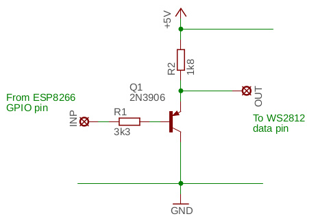
A PNP and a couple resistors never fails though
 neat shoal
Good evening innocent .
excuse me .. I'm trying to program ATMEGA328 with FTDI and TTL adapter but always have this error
 neat shoal
Good evening innocent .
excuse me .. I'm trying to program ATMEGA328 with FTDI ...
neat shoal
neat shoal
Good evening innocent .
excuse me .. I'm trying to program ATMEGA328 with FTDI ...
this is my ATmega328 circuit it use 16MHz crystal with 22pF capacitor

I'm using this ftdi and ttl

 neat shoal
Good evening innocent .
excuse me .. I'm trying to program ATMEGA328 with FTDI ...
neat shoal
neat shoal
Good evening innocent .
excuse me .. I'm trying to program ATMEGA328 with FTDI ...
so what I'm doing wrong .. and is there any other way to do it
north stream
Could be a voltage issue (3.3V vs 5V), speed issue, programmer type/bootloader issue, port issue, or hardware problem
gilded swift
I though you needed to put a bootloader on the atmega328p before you could program with UART?

circuito.io blog
The ATmega328p microcontroller is the beating heart of the Arduino Uno. Learn how to burn its bootloader in a few simple steps, so you can use it as a standalone unit.
neat shoal
north stream
Could be a voltage issue (3.3V vs 5V), speed issue, programmer type/bootloader i...
it's on 5V .. also I'm trying to do that on 3.3 because I'm gonna use circuit has ATmega328 working on 3.3V
neat shoal
gilded swift
I though you needed to put a bootloader on the atmega328p before you could progr...
it's already done and i can program it with Arduino uno but i want to program it by ftdi or ttl on 5V and 3.3V
gilded swift
Hmm.. once the bootloader is loaded, so long as your RX/TX lines are right it should work.
north stream
You'll need to set the programmer type to match your bootloader too
neat shoal
gilded swift
Hmm.. once the bootloader is loaded, so long as your RX/TX lines are right it sh...
i tried all ways of contacting rx and tx even the opposite way
neat shoal
north stream
You'll need to set the programmer type to match your bootloader too
i ll try to do that ..but sorry i have no idea how to match the bootloader to my programmer 😅
gilded swift
If you put the Uno bootloader onto the chip, you should program it as an Uno
 fathom mauve
I have a sony spresense / arduino comaptible board, I have hooked up a EVK-701 sensor chip with a KX126 accelerometer attached to it. https://github.com/RohmSemiconductor/Arduino/tree/master/KX126 I can get the x,y,z, data from it via serial out. I am curious though, what are all the calls possible for this chip? Is it defined in the keywords.txt file (see above link)?? Is there a way to define the sensor update interval frequency? Is it pre-defined somewhere? I see get_val and get_rawval, i see init, one would think I set the update HZ in init. I see no documentation anywhere on how to actually use this library. The examples work fine, but I wonder if there is more to its functionality than I am seeing. Any pointers would be helpful. Im still newish to arduino.

GitHub
Adruino libraries and samples for Rohm Sensors & Bluetooth LE - Arduino/KX126 at master · RohmSemiconductor/Arduino
neat shoal
gilded swift
https://www.circuito.io/blog/atmega328p-bootloader/
thank you so much .. i just burn new bootloader and it works even with 3.3
neat shoal
 neat shoal
gilded swift
Nice work! 🙂
neat shoal
gilded swift
Nice work! 🙂
🤍🤍🤍
gilded swift
It took me a month to have the light bulb moment on programming the first Arduino I designed myself. It’s awesome to be able to others get there faster 🙂
neat shoal
gilded swift
It took me a month to have the light bulb moment on programming the first Arduin...
really appreciate all that time you spent 😇
brazen falcon
gilded swift
If you put the Uno bootloader onto the chip, you should program it as an Uno
Chinese nano clones are like a box of chocolates, you never know what bootloader you're going to get.
gilded swift
Yup
 random light
i like chocolate
brave maple
I'm still trying to decide what parts to get; I think I want to do something a bit more basic with my LEDs, so currently I just have 2 8x8 NeoPixel matrices, and an arduino UNO. What would be a good power source to use if it's to be used in a portable project (the LEDs and arduino are for a costume)? Ideally I'd like something rechargeable to cut down on batteries and be able to power on the go when needed
heavy star
A PowerBoost board and a LiPo would be an easy way to go
The PowerBoost boards charge, give you 5V out, and can even have a USB port to power things from
An LC709203F fuel gauge can be used to monitor power if you want to get fancier
north stream
Alternatively, you could use a lower voltage board like a Feather and run the whole thing directly from a LiPo cell. The LEDs wouldn't be quite as bright, but you wouldn't need a PowerBoost.
fathom mauve
I'm still trying to deduce how the access that i get thru arduino ide using the provided library for the chip https://github.com/RohmSemiconductor/Arduino/tree/master/KX126 works. What calls can I make to get data from it? Can I set the g range (the chip docs say it has 3 modes)? Can I change the update frequency? How? Any pointers are much appreciated.
GitHub
Adruino libraries and samples for Rohm Sensors & Bluetooth LE - Arduino/KX126 at master · RohmSemiconductor/Arduino
fathom mauve
basically, im looking for someone to tell me if thats the only driver for this chip?
it seems really limited.
i feel like im missing something.
livid osprey
Technically, that's all the drivers needed to do whatever you want. Problem is, it's pretty low-level compared to something someone like Adafruit would provide, as it requires some understanding of the registers and what to write to and read from them. The example sketch provides you exactly what you need to get started, but to really do everything else, you'll need to pull up the datasheet and figure out which registers to read from and write to.
All of the other functions are kinda hidden in the write() and read() functions, which simply write or read data over I2C.
I pulled this datasheet from Mouser, but it's quite a handful to try to digest it all... https://www.mouser.com/datasheet/2/348/KX126-1063-Specifications-Rev-1.0-1154286.pdf
fathom mauve
does this stuff from the datasheet exist in this driver?
 fathom mauve
can i use the registers to set it to differnet modes in arduino ide?
leaden walrus
yes/no. you can access that register, and any register, and read/write whatever you want.
that driver has nothing special w.r.t to those register though
looks like get_rawval and get_val are the only methods that actually do anything besides basic register read/write
fathom mauve
okay thats what I thought, I wanted to be 1000% sure of that before proceeding.
so like... the arduino driver provided by rohm just doesnt take advantage of the other setting provided by the chip?
its api just lacks those calls?
again... is there any way to make my own driver to gain access to those calls if i wanted to (i dont, i may, i will just use a different arduino based IMU sensor with more functionality)
livid osprey
You could, if you figure out the proper register writes to do so.
The code definitely includes definitions for different sensitivity settings, it just lacks a dedicated configuration function
brave maple
@heavy star @north stream thank you! This helps a lot in deciding what to buy^^
also, i got the matrices soldered so I tried coding them again since they would now have a stronger connection (originally they were just held together to their cables by painter's tape), but i've run into an error suddenly?
Arduino: 1.8.13 (Windows 10), Board: "Arduino Uno"
Sketch uses 9364 bytes (29%) of program storage space. Maximum is 32256 bytes.
Global variables use 291 bytes (14%) of dynamic memory, leaving 1757 bytes for local variables. Maximum is 2048 bytes.
An error occurred while uploading the sketch
An error occurred while uploading the sketch
avrdude: stk500_recv(): programmer is not responding
avrdude: stk500_getsync() attempt 1 of 10: not in sync: resp=0xc2
avrdude: stk500_recv(): programmer is not responding
avrdude: stk500_getsync() attempt 2 of 10: not in sync: resp=0xc2
avrdude: stk500_recv(): programmer is not responding
avrdude: stk500_getsync() attempt 3 of 10: not in sync: resp=0xc2
avrdude: stk500_recv(): programmer is not responding
avrdude: stk500_getsync() attempt 4 of 10: not in sync: resp=0xc2
avrdude: stk500_recv(): programmer is not responding
avrdude: stk500_getsync() attempt 5 of 10: not in sync: resp=0xc2
avrdude: stk500_recv(): programmer is not responding
avrdude: stk500_getsync() attempt 6 of 10: not in sync: resp=0xc2
avrdude: stk500_recv(): programmer is not responding
avrdude: stk500_getsync() attempt 7 of 10: not in sync: resp=0xc2
avrdude: stk500_recv(): programmer is not responding
avrdude: stk500_getsync() attempt 8 of 10: not in sync: resp=0xc2
avrdude: stk500_recv(): programmer is not responding
avrdude: stk500_getsync() attempt 9 of 10: not in sync: resp=0xc2
avrdude: stk500_recv(): programmer is not responding
avrdude: stk500_getsync() attempt 10 of 10: not in sync: resp=0xc2
nevermind, it fixed itself when i closed out the program and unplugged then plugged in the arduino
i think it was because a cable moved or something
heavy star
Arduino weird
 reef dirge
Anyone have a couple of moments to help me tease out what's going on with my arduino ISP? I'm trying to re-program the ATtiny2313a that came with the generic USPTinyISP (I don't necessarily trust the folks who flashed it, so I wanted to roll my own). I'm trying to program the ATtiny on a breadboard, I have the 10uF decoupler cap on the ISP reset pin. No matter what I do tho, either there's something wonky about the ArduinoISP sketch, avrdude, or the ATtiny simply isn't responding for some reason (identifier 0x000000).
I know the ATtiny isn't bricked, because I just used it (against my better judgment) to read the flash from the arduino
The only thing I can think of is maybe the attiny has a fuse bit set for the 12MHz crystal oscillator, and the arduino isn't clocking it that fast?
 slate pendant
hey, I'm just learning about PortManipulation in arduino - there aren't many good tutorials or examples for it...
now to my problem: I want to have the PIN registers #defined at the top of my code and use them like this
(so PIN{_Port} would get replaced by PINF and P{_Port}{_PortBit} should become PF7 at compile time... I can't figure out the character to (de-)reference (?) the PIN part of this statement.. any help/tutorials/tricks for PortManipulation? kinda already got the basics and yes, I need its speed.
please @ me if you have an answer

 stable forge
you could use a c pre-processor macro and the ## concatenation operator. See https://stackoverflow.com/questions/5106280/string-concatenation-using-preprocessor# (not the accepted answer, which is not really helpful)
slate pendant
thanks! I think that's exactly what I was looking for!
 old dove
I have a QT Py connected via USB C to my PC. Uploads to it via File Explorer or Arduino IDE usually fail. I managed to get a basic NeoPixel sketch to run once, but not again despite no changes. Any writes to the QT Py cause the COM port to drop out. Tried 3 different cables and 2 QT Py boards (with and without an attached I2C device, the AHT20). Cables work fine to communicate with other devices, can't verify current rating for PC's USB C port.
Recommendations as to what to try next?
stable forge
old dove
I have a QT Py connected via USB C to my PC. Uploads to it via File Explorer or ...
qt py M0 or RP2040?
If QT Py RP2040, update philhower core to 1.9.5
old dove
M0, sorry for not specifying. Whoops
stable forge
old dove
M0, sorry for not specifying. Whoops
the symptoms are completely reminiscent of an RP2040 problem, which is why I asked. Just to double check, there is only one pushbutton on the top, and it doesn't say RP2040 on the bottom. Assuming M0, did you add a flash memory chip on the bottom, or not?
If you double-click the reset button, does the QTPY_BOOT drive show up?
old dove
@stable forge Definitely only one button. Haven’t soldered an SPI chip on it. They’re straight from the packaging.
@stable forge yes, it will always show up. It’s only when I go to write a file to it (or use Arduino IDE to upload a sketch) that it drops. The COM port completely disappears from Device Manager after a second or two. When I press reset, it comes right back
stable forge
the comport is expected to go away. Have you used other of our boards with Arduino and they've worked, on this computer?
old dove
@stable forge I’ve used them previously, but that was on my older PC. This is my first attempt with this one. It did work for a sketch the one time without issues. Then it went back to the above behavior. Connecting a Trinket doesn’t exhibit the same issues
stable forge
you are selecting the QT Py board in the Boards menu, right? What error is showing in the arduino log?
which kind of trinket?
Are the Arduino and Adafruit SAMD board packages both up to date?
old dove
QT Py connected

@stable forge I just installed Arduino on this PC yesterday. Retrieved all libraries then. Installed Arduino SAMD at that point. Now looking within the Library Manager I'm struggling to find it however to give you the version.
stable forge
not library, BSP, but if it's yesterday, they will be very new. I assume you must have installed both the Adafruit and Arduino board packages
old dove
@stable forge yes, I did. Was walking through the learn article on adafruit.
https://learn.adafruit.com/adafruit-qt-py/using-with-arduino-ide
 stable forge
so what kind of Trinket, and do you have any other Adafruit boards to try
old dove
Trinket M0. I also have a Circuit Playground express here, though I'll have to hunt down a mini USB data cable for it.
stable forge
so the trinket M0 is working fine, is that right? You can upload Blink or whatever to it with the current setup/
(I am setting up a Windows machine to try this)
old dove
let me try again to verify.
@stable forge Ok, it wrote to the Trinket M0 without issue. Popped up some windows errors afterwards, but the device is blinking its red LED as expected.
stable forge
what are the Windows errors?
old dove
@stable forge They went by quickly. It said something about the COM port. Then I believe the drive for it disappeared. Expected, correct?
stable forge
if it said TRINEKTBOOT disappeared without being ejected or something, yes
ok, I am trying a qt py ... one sec
old dove
@stable forge Here's what I see after running an upload to the QT Py
 stable forge
did you double-click the reset button, and then select the appropriate port, so it was checkmarked?
is the USB C cable plugged in to the same USB port that you tried with the trinket?
old dove
@stable forge No to both. Let me try that
stable forge
if you are using a USB hub, try not to use it if you can
old dove
@stable forge I'm plugging directly in. QT Py uses USB-C, so I was using my actual USB-C port. Trinket was plugged into a USB-A 2.0 port. Using an A to C cable that claims to be USB 3.0 in the same port gives the dreaded red LED of bad cableness 😐
slate pendant
stable forge
you could use a c pre-processor macro and the ## concatenation operator. See ht...
I kinda got it now but I cant get _Port to resolve as F and simultaneously being right next to DDR.
 old dove
@stable forge same for a micro to USB-C adapter. Have used both to sync with my iPad to this machine on a different USB port. Ugh.
USB-A 3.0 port gives green light.
Upload fails same as before. Then get this windows error.
 stable forge
Let's clean up all the ports. Download the DeviceCleanup Tool from this page (scroll down a bit to find it): https://www.uwe-sieber.de/misc_tools_e.html. Run the tool as Administrator. Unplug all the boards before running it. Delete basically all the devices you see. It won't hurt. They will come back if you plug them in again.
old dove
@stable forge Ok. Yeah, definitely in a mess now. Trinket M0 is giving failures now as well.
stable forge
quit arduino as well
slate pendant
I had a flashing error before aswell - I just cut power and plugged it back in during compile so the upload is right when it comes back on. Was an issue with the serial port being clogged up from the sketch
old dove
@stable forge Success! At least one round of getting Blink onto the QT Py. Used my USB-A 3.0 port with the direct A-> C cable after wiping all devices.
Now I'll see if it can do it again....
@dinh
@stable forge I changed the color of the blink... Now it fails:
No device found on COM4
An error occurred while uploading the sketch
double-click reset again and choose the port
old dove
I did.
stable forge
did the port say COMn (Qt Py...) or something like that?
old dove
@stable forge It did not. I had unplugged it since the first success. Came back on the same COM port, but no name next to it.

The COM port just disappeared without my attempting to upload. Didn't do anything but take that screenshot and type here.
stable forge
was it COM4 the first time?
if you double-click to get QP_PYBOOT, then a COM port shows up. I assume. Is it COM4?
old dove
@stable forge Yes. I just did another round of Device cleanup and it worked without issues. Showed as it should in the list.
 stable forge
is that with QT_PYBOOT showing?
old dove
I believe it was showing when I started the Upload, yes
Uploading again, when the upload is in the middle I get QT_PYBOOT popping up. Then it disappears and the QT Py starts the correct blinking.
stable forge
what is the model of Windows computer you are using? You mentioned it's new. Did it come with various utility programs installed, or did you install some? Are you running a third-party antivirus, or some backup or disk monitoring program?
Do you have another computer to try this on?
old dove
It's a custom PC (Software Dev here). AMD Ryzen 3700X. Windows 10 Pro. Lots of developer tools installed (though none for micro controllers other than what we've discussed). No anti-virus.
stable forge
The very first upload after wiping the devices, always double-click reset, set the port, and try an upload. Then unplug, double-click reset, set the port, and try uploading again
we haven't heard of specific issues like this with Ryzen
but who knows?
@slate pendant also specific issues with USB C?
slate pendant
no I had micro USB and type A
old dove
after unplug it showed up as COM5. Failure on upload.
stable forge
it showed up as COM5 after double-click? The COM port when QT_PYBOOT is showing should be consistent
old dove
yes, COM 5 after double-click. QT_PYBOOT drive comes up, but then disappears after ~30s (along with the COM5 port)
livid osprey
Did you re-plug the cable into the same USB port...?
old dove
@livid osprey Yes. I've been unplugging the QT Py from the end of the cable, haven't touched how the cable is plugged into the PC
stable forge
the disappearing is very odd. QT_PY should stay visible indefinitely
If you have another Windows machine to try, that would be a helpful test to narrow it down to your machine. I'd double-check the list of installed apps and drivers, including using the old "Programs and Features" window, not just the new "Apps" listing. The older one sometimes shows more.
old dove
Swapping to a USB 2.0 port leads to the red light of unhappiness. Both USB-A 3.0 ports exhibit the swap to COM5 + disappearing after a delay behavior.
USB C port acts the same as the 3.0 ports with it disappearing after a delay
stable forge
does your motherboard have some kind of USB power saving feature turned on or anything? I'm at a loss here.
slate pendant
also what motherboard? potentially Asus Strix x470-f?
old dove
I swapped to USB ports on the back and have been running through some scenarios.
- After wiping all devices and plugging in the first time it shows up as COM4. If I then double-click the reset button it swaps to COM5 and the QTPY_BOOT drive appears. If I just sit there at that point then it will disappear after a bit.
- After a wipe and plug in for the first time with it on COM4 the Arduino IDE shows it with the proper name and such.
Now that I've fiddled with it some the blink program is no longer running and I've been unable to upload to it again.
@slate pendant Gigabyte X570 Ultra Motherboard
@stable forge No power saving modes that I'm aware of, no. Weird issue!
slate pendant
slate pendant
I kinda got it now but I cant get _Port to resolve as F and simultaneously being...
we coming back to my issue?
hmm
stable forge
slate pendant
I kinda got it now but I cant get _Port to resolve as F and simultaneously being...
There's only one # in line 20 instead of ##
old dove
some of my messages keep disappearing now.
stable forge
old dove
I swapped to USB ports on the back and have been running through some scenarios....
it will show up as two different COM ports: one is when the Arduino program is running, and one is when the QT_PYBOOT drive is present.
old dove
I can't tell which messages are going through. I send them, they show for a second, then they're gone. Discord being weird too
livid osprey
old dove
some of my messages keep disappearing now.
Probably the bot saw something that triggered its antispam or language filter...
stable forge
I tried leaving a QT Py plugged in for a while and it did not disappear (I had not seen that before anyway). I think this is a USB driver issue or some utility program issue
livid osprey
If it wasn't going through, your message would show up on your screen in red
stable forge
your message hit the banned words filter
old dove
@stable forge Ok. I'll try this on my laptop later. Need to get some work done for a while anyway. Was trying to get this rolling while taking a break.
@livid osprey It didn't show in red. Just disappeared
stable forge
i asked another staff person with a lot of support experience, who also has not seen this problem
livid osprey
Yeah, that's a banned word AFAIK
old dove
What got removed:
 stable forge
i deleted that; you said something else beginning with h
old dove
@stable forge Very odd... the text above is what I copy/pasted in and it was deleted multiple times.
anyway, not important. Thanks for trying to figure this out. I'll dig more later.
stable forge
yes, I see it in the log. You put it in quotes above, that should not make a diff, but ...
slate pendant
stable forge
There's only one `#` in line 20 instead of `##`
yup but it doesnt depend on that - the _Port doesnt get resolved to a 7 when using ##
#define __DDRREG DDR ## _Port
resolves to DDR_Port
stable forge
is there #define DDR somewhere?
slate pendant
nope
stable forge
then you have two strings which it just concatenated "DDR" and "_Port"
is there a #define _Port somewhere?
Could you show a whole reduced example that does not work? I am seeing the snippets but not the whole context
This might be helpful: https://gcc.gnu.org/onlinedocs/gcc-4.8.5/cpp/Stringification.html
also would it help to use a macro with arguments (e.g. port number, etc.)?
slate pendant
//Setup
#define _Port F
#define _PortBit 7


//Script variables
#define __DDRREG DDR ## _Port
#define __PORTREG PORT ## _Port
#define __PINREG PIN ## _Port
#define __PIN P ## _Port ## _PortBit


void setup() {
  __DDRREG &= ~(1<<__PIN);
  Serial.begin(9600);
  delay(5000);
}
once I get that DDRREG working I can do it with the others and its nice code
__DDRREG should become DDRF
__PORTREG should become PORTF
__PINREG should become PINF
__PIN should become PF7
or is there a better way to adress ports?
that maybe looks the port up in the arduino ide internal portmapping table
stable forge
#define __DDR(port) DDR##port
#define __PORT(port) __PORT##port
#define __PINREG(port) PIN##port
#define __PIN(port, pin) P##port##pin
@slate pendant
I'm still not quite sure what you want to do here. There are a bunch of macros in the arduino pin header files that might do what you want: see variant.h , which has stuff liek:
extern "C" unsigned int PINCOUNT_fn();
#endif
#define PINS_COUNT           (PINCOUNT_fn())
#define NUM_DIGITAL_PINS     (19u)
#define NUM_ANALOG_INPUTS    (5u)
#define NUM_ANALOG_OUTPUTS   (1u)
#define analogInputToDigitalPin(p)  ((p < 6u) ? (p) + 24u : -1)

#define digitalPinToPort(P)        ( &(PORT->Group[g_APinDescription[P].ulPort]) )
#define digitalPinToBitMask(P)     ( 1 << g_APinDescription[P].ulPin )
//#define analogInPinToBit(P)        ( )
#define portOutputRegister(port)   ( &(port->OUT.reg) )
#define portInputRegister(port)    ( &(port->IN.reg) )
#define portModeRegister(port)     ( &(port->DIR.reg) )
#define digitalPinHasPWM(P)        ( g_APinDescription[P].ulPWMChannel != NOT_ON_PWM || g_APinDescription[P].ulTCChan
nel != NOT_ON_TIMER )
I think this would not allow for setting the PORT from the top of the script (configuration, deployability etc)
but your second message might be really useful
 copper echo
how would I go about making something with an Arduino so that when I push a button one servo rotates 90 degrees, and another rotates -90 degrees, and when I push another button, the servos go back?
leaden walrus
start by dealing with buttons and servos separately, to understand the basic of each
and then try merging the two together to achieve what you're after
 mossy locust
I have probably quite the beginner question - How do you figure out the pin numbering of the Adafruit boards for Arduino?
Like, is there some place, some documentation where they are defined for all boards? (Specifically Feather m0 and Gemma m0, but would be interested in all of them)
Thank you!
mossy locust
Are the purple numbers on each of the pins the one you would use in the Arduino IDE?
leaden walrus
yep
you can also use the silkscreen labels
the small white text on the board itself
digital pins will have a number like 13
analog pins will be prefixed with an A, for example A0
but a lot of times pins can have multiple functions, and the silkscreen can't document them all, just not enough room on the board
for example, on the feather m0 express, 9 is also A7
similarly, the analog pins can be digital pins, A0 is 14, etc.
mossy locust
First of all thank you. Can you point me to where exactly the pins are defined for the IDE to use? Is there some file that I could change to change the pin numbering or are the definitions buried in some binary files?
vivid rock
there are board definition files, variant. h and variant.cpp

GitHub
Contribute to adafruit/ArduinoCore-samd development by creating an account on GitHub.
mossy locust
Thank you so much! That's exactly what I was looking for
leaden walrus
i wouldn't mess with the BSP files though
vivid rock
but not every pin can be used for every function. e. g. not every pin can be used as PWM - you need to consult the datasheet
mossy locust
leaden walrus
i wouldn't mess with the BSP files though
Why?
leaden walrus
why do you want to change pin numbers?
 lime ridge
Would kubernetes clusters be overkill for an arduino driven network that consists of 1 sensor, maybe geotracking and an img from an onboard cam. Could be a bunch of devices. Data would only be a few bytes of random numbers unless the camera or gps is used. I kinda want people to have their own profiles and data based on the device analytics and user input. I've seen cloud services, caas platforms for machine learning, not sure what route to go to put it all together.
stone stone
https://puu.sh/IdU86/59b93b3995.png
are these the right settings for an Adafruit RP2040?
 leaden walrus
yes, if you are using a Feather RP2040, but Adafruit has more the one RP2040 based board. do you have a feather?
one of these?
https://www.adafruit.com/product/4884
note you also need to specify the Port (unspecified in your screen cap)
stone stone
leaden walrus
one of these?
<https://www.adafruit.com/product/4884>
yes!
im on COM4 so im ok there
having some issues now with LED controls, but im making a little headway
 arctic stump
I have some (hopefully basic) questions about multiple power sources in one circuit.
I want to control an MCP4725 I2C DAC with an Nvidia Jetson Nano which runs at 3.3V, and read the DAC output using an Arduino.
I'm about to hook up the three devices as pictured. The DAC has a common ground and the Arduino's VCC is not connected. I believe this should work without issue, can some please reassure me?!

Ultimately the plan is to control an e-bike controller with the DAC, which I have done successfully with just the Arduino. The e-bike controller's throttle uses a hall sensor on a 5V line which I'm trying to emulate with the DAC.
The DAC is going to output a voltage up to the VCC input voltage (3.3 in the above picture). Can I safely connect the Arduino 5V VCC to DAC?
I'm worried the 5V will flow into the Jetson Nano and damage it. Would a diode on the Jetson's 3.3V VCC protect it?
 arctic stump
I'm also unsure if connecting both 3.3 and 5V to the DAC VCC will cause problems with it understanding the I2C communication from the 3.3V Jetson Nano
 inland gorge
arctic stump
Ultimately the plan is to control an e-bike controller with the DAC, which I hav...
inland gorge
arctic stump
Ultimately the plan is to control an e-bike controller with the DAC, which I hav...
Do not connect a 5V Arduino to a 3.3V device like a Jetson Nano. You will damage the 3.3V device
Instead use a 3.3V Arduino (like a Feather M0 or Arduino Nano 33 or Nano RP2040.
arctic stump
As a general rule, can I connect two devices of the same voltage without worry, and connect two grounds from boards of different voltages without worry?
stone stone
hi guys, im finally running neopixels! but i really dont fully understand some code i copy pasted
Adafruit_NeoPixel pixels(NUMPIXELS, PIN, NEO_GRBW + NEO_KHZ800);
i added Neo_GRBW to the original Neo_GRBW since im running SK6812s
but i have no idea what the Neo-KHZ800 means, unless that is in reference to the type of pixels im running?
cedar mountain
arctic stump
As a general rule, can I connect two devices of the same voltage without worry, ...
Yes, that's a decent general rule.
 hexed parrot
Hi I am using the very cool Feather nRF52832 and would like to save some data to it’s EEPROM like you can do with many Arduinos using the:
#include <EEPROM.h>
EEPROM.write(address, data)
EEPROM.read()
EEPROM.update
I just get a:
“EEPROM.h: No such file or directory” which makes sense I guess since that is not made for the feather.
Wondering if the Feather nRF52832 has an EEPROM and how I can write/read from it?
Thanks for any help.
Well i did find some information that the 'NRF52" doesnt have an EEPROM. But somehow you can try using NFFS. But its all over my head. https://forums.adafruit.com/viewtopic.php?t=88272
I just would like to store one INT in non-volatile memory. Are there and easy/tricky ways to do this?
 wheat crag
attach an spi flash chip or sd card?
hexed parrot
I don't have any room. any way to do it in code?
wheat crag
unless you have non-volatile arduino accessible memory to write to, you can’t
hexed parrot
The link above talks about using NFFS but i dont know anything about that. Is that a way to store data?
wheat crag
it’s an NRF feature that’s basically a tiny file system that you can read and write to; trouble is all the links I could find to example code are dead (on my phone at least; there’s likely some examples on adafruit’s github)
hexed parrot
Thanks, I dont think I am going to mess this that unless I had a clear guide. Thank you for your help.
 jolly valve
stone stone
but i have no idea what the Neo-KHZ800 means, unless that is in reference to the...
jolly valve
stone stone
but i have no idea what the Neo-KHZ800 means, unless that is in reference to the...
The NEO_KHZ800 is an option for an 800kHz data rate. There is also an option for 400kHz. Generally the faster 800kHz should work.
stone stone
it is working nicely
have another question
#include <Adafruit_NeoPixel.h>
#ifdef __AVR__
#include <avr/power.h>
#endif
#define PIN        12
#define NUMPIXELS 6

Adafruit_NeoPixel pixels(NUMPIXELS, PIN, NEO_GRBW + NEO_KHZ800);
#define DELAYVAL 1000

void setup() {
#if defined(__AVR_ATtiny85__) && (F_CPU == 16000000)
  clock_prescale_set(clock_div_1);
#endif


  pixels.begin();
}

void loop() {
  pixels.clear();
 pixels.setPixelColor(6,pixels.Color(255,0,0,0));
 pixels.setPixelColor(6,pixels.Color(255,0,0,0));
   delay(DELAYVAL);
 for (int i = 0; i < NUMPIXELS-2; i++) {
    pixels.setPixelColor(i, pixels.Color(0, 100, 0, 50));
    pixels.show();
  }
  delay(DELAYVAL);

  }
it seems i cannot individually set the pixel values using the code i set here?
specifically the part about setting pixel colors
i can get the loop to work just fine, but the two i assign on their own arnt working proper
jolly valve
The pixels are 0 based indexing, so the last one would be 5, not 6. I think in the first two lines you should be using 4 and 5.
stone stone
oh then im borkin this up, ty
brazen falcon
jolly valve
The NEO_KHZ800 is an option for an 800kHz data rate. There is also an option for...
KHZ400 is for WS2811-based LEDs.
 plain kayak
Hi,
I wanna copy a logo for a TFT display using the adafruit library, depending on a switch case, to keep the displayin code clean, I tried to store the right logo into a pointer to later use it on the display.drawBitmap function.
Problem is that it fails at compile with this error:
error: incompatible types in assignment of 'const unsigned char*' to 'const unsigned char* [385]'
The code:
const unsigned char unknowLogo [] = {
0x00, 0x00, 0x00, 0x00, 0x00, 0x00, 0x00, 0x00, 0x00, 0x00, 0x00, 0x00, 0x00, 0x00, 0x00, 0x00,....
};

const unsigned char *logoToUse[385];
switch (fs)
  {
    case FS_UNKNOWN:
      logoToUse = (const unsigned char *) &unknowLogo;
      break;
      ...
It fails on the assignment line: logoTouse =...
Any ideas on how to fix this please ?
north stream
unknownLogo is a pointer to const unsigned char, where as logoToUse is an array of pointers to const unsigned char. Both allocate storage, and I'm guessing you don't want or need to do that. I'd just replace the logoToUse line with ```arduino
const unsigned char * logoToUse;
Thks, yes I tried that before without success, but at that time I didnt forced cast to (const unsigned char *) &unknowLogo
This works:
const unsigned char *logoToUse;
  switch (fs)
  {
    case FS_UNKNOWN:
      logoToUse = (const unsigned char *) &unknowLogo;
      break;
This doesnt:
const unsigned char *logoToUse;
  switch (fs)
  {
    case FS_UNKNOWN:
      logoToUse = &unknowLogo;
      break;```
```src\main.cpp:232:17: error: cannot convert 'const unsigned char (*)[384]' to 'const unsigned char*' in assignment
       logoToUse = &unknowLogo;
^```You also do not want the & character, which takes the address of what is already a pointer.
I don't think you need the cast either.
plain kayak
with this:
logoToUse = unknowLogo;
it will take the address of the variable directly ? 😕
north stream
Yes, unknowLogo is an array, and in C, arrays are referred to by address.
plain kayak
okay, indeed it works, thanks 🙂
slate pendant
old dove
I swapped to USB ports on the back and have been running through some scenarios....
https://youtu.be/AhvDJaFdmw8?t=309
Ryzen 3000 has USB issues (min 5:10)

Thanks to 3CX for sponsoring this video! Get 3CX free today at www.3cx.com/?src=ltt
In this episode, callers navigate a hilarious phone maze in hopes of getting personal IT tech support from Linus himself.
Discuss on the forum: https://linustechtips.com/topic/1376180-press-1-for-tech-tips-sponsored/
►GET MERCH: http://www.LTTStore.com/
►SUPP...
 next basin
Ok I have a question about working with Arduino BLE. I have a stepper motor that I want to control remotely. I have 3 modes for control that are each contained in there own Arduino programs. Is there a way that I can change programs remotely without uploading the new code?
Currently the solution I'm working on is containing each program in a giant while loop and then switching between while loops by sending a command to the arduino.
Are there any more elegant solutions that you guys/girls know of?
cedar mountain
That general approach of using higher-level program logic to switch between operating states is indeed what people typically do.
slate pendant
next basin
Currently the solution I'm working on is containing each program in a giant whil...
using functions and calling the functions via a command?
 native dagger
Is arduino suitable for very hi safety priority purposes or would straight C++ be better?
north stream
I wouldn't use either, perhaps Rust would be a better choice
native dagger
I have a smidgen of C++ experience, how hard is it to learn rust from scratch? My company wants me to build a human sized one of these that is spun by a motor while people stand on it. I have some concerns about safety, to put it mildly.
 north stream
I honestly don't know, as I haven't yet learned Rust myself. However, this looks like a fairly conceptually simple system, so other options include sticking with Arduino and doing rigorous analysis and testing, or adding hardware to enforce safety features.
native dagger
Yeah system wise it's pretty simple, just a single actuator and feedback sensor, but since people are gonna be on the thing, it needs to be safer than safe
I was thinking 2rpm max with a .1-.2rpm/s acceleration
north stream
I also prefer a belt-and-suspenders approach to safety
native dagger
What's that idiom?
north stream
It refers to keeping your pants up: some people wear a belt, some people use suspenders. However, the saying goes that if you want to be double sure your pants don't fall down, you could wear both.
It's an old idiom (not a lot of people wear suspenders these days), but seemed applicable
cedar mountain
I think the overall system design will be more critical to safety than the choice of programming language or framework. For example, if your feedback sensor dies and starts giving bogus constant data, does that cause the motor controller to accelerate to max speed, or to shut everything down? Etc.
north stream
Perhaps specifying a motor that cannot go faster than the desired max speed.
native dagger
Yeah I was hoping there were big slow motors for stuff like this. I'm going to call around drama departments at colleges nearby and see if anyone has a rotating stage I can look at
cedar mountain
You're unlikely to find a motor that inherently runs slowly, but you may be able to find one with integrated gearing.
native dagger
Would a pulley system be acceptable?
cedar mountain
A belt drive? Yep, that could certainly work, and would be quieter than metal gears, I expect.
native dagger
Quiet is preferable. And easy to service
 woeful drift
native dagger
I have a smidgen of C++ experience, how hard is it to learn rust from scratch? M...
woeful drift
native dagger
I have a smidgen of C++ experience, how hard is it to learn rust from scratch? M...
Ah, is this the project where you were asking how to solve for the torque your motor needed?
A giant "Weihnachtspyramide"?
 patent bolt
Not really arduino but is this posable it worked for a second

 broken viper
What's it connected to?
broken viper
patent bolt
Not really arduino but is this posable it worked for a second
It should from your picture, but I can't see very well
patent bolt
That's it
broken viper
patent bolt
That's it
What's the board? A Nano clone?
patent bolt

 broken viper
That's just a FTDI programmer, it looks like to me. Then no, it shouldn't work
broken viper
A Nano or an Uno would be good
patent bolt
I got uno
broken viper
OK, that'd do fine
broken viper
👍
 formal python
hi there, I created a void who spam a key, it's possible to creat a buffer for this void ?
north stream
I'm not sure what you mean by void here, perhaps a data type? Usually buffers contain a certain size of data, but void technically means nothing, some languages use a void pointer as a pointer to anything.
native dagger
woeful drift
Ah, is this the project where you were asking how to solve for the torque your m...
Oh I knew how to solve, I just wanted a sanity check that using CAD MOI would work
woeful drift
I misunderstood then, yeah CAD would work for that, the thing that gets me with finding MoI with CAD is sometimes I forget which axes I aligned my parts too
cedar mountain
north stream
I'm not sure what you mean by void here, perhaps a data type? Usually buffers c...
Sometimes people see void loop() and conclude that void means "function".
 rough torrent
If it is a function to spam a key, then what does the buffer do???
north stream
 rocky schooner
How do I tie an Analog In pin (like `A0`) high or low?
rocky schooner
How do I tie an Analog In pin (like `A0`) high or low?
I'm not sure what you're asking. Do you mean a pull-up resistor, or just connecting it to a fixed level or what?
rocky schooner
Kind of like a pull up resistor bit within the arduino
With the IO pins I can set the mode to OUTPUT and then they are pulled down internally
I was wondering if that's possible with the Analog input pins as well
@north stream

Ok. Different question: on this pinout diagram it says that pins A6 and A7 are Analog only. Do you hav a better idea how to get the digital value anyways besides writing a function that checks whether it's over some voltage?
livid osprey
rocky schooner
Ok. Different question: on this pinout diagram it says that pins A6 and A7 are A...
No, actually that's exactly how you would get a digital value from an analog input. Better ideas wouldn't be doing it differently, they would be doing it more efficiently?
rocky schooner
K
north stream
rocky schooner
I was wondering if that's possible with the Analog input pins as well
Yes, you can use the analog pins as digital pins that way.
rocky schooner
north stream
Yes, you can use the analog pins as digital pins that way.
No. I meant whether I could pull them down internally
livid osprey
No, I assume that's the reason they're "exclusively analog."
If you pull them externally, you might be able to get an artificial digital input, but you would still suffer from the same drawbacks an analog pin has due to the way it's hardwired to the ADC block.
rocky schooner
What's an ADC block?
I'm just gonna fire the next question: I use pins 0...7 on my board. Pins 0 and 1 are RX and TX (I kinda know what they do, I've used them before).
Now if I write C Serial.begin(9600); into setup I can see the stuff it sends (on the serial monitor) but also pins 0 and 1 are occupied. As far as I know RX and TX aren't used for USB communication (at least I used them for a different protocol). Can I keep the serial data transfer but without pins 0 and 1 being occupied?
north stream
I'm a little unclear on what you mean by RX and TX aren't used for USB, but the serial data for the Nano does use pins 0 and 1.
You can view the schematic here https://content.arduino.cc/assets/NanoV3.3_sch.pdf
livid osprey
rocky schooner
What's an ADC block?
It's just the part of the MCU that handles all the analog-to-digital conversions. Most pins are on a reassignable port, but these two are not.
livid osprey
rocky schooner
I'm just gonna fire the next question: I use pins 0...7 on my board. Pins 0 and ...
RX and TX are the pins that connect to the USB through the USB-UART bridge, there is no way to separate the two.
rocky schooner
Ok :( I'm really struggling with my pins now. I need 8 input and 8 outputs. Also a few trigger buttons for controll of the thing are necessary. But they are used up really fast. Maybe I'll put my output on a shift register so I can make 4 pins as if it were 8
livid osprey
8 inputs and 8 outputs?
livid osprey
rocky schooner
Ok :( I'm really struggling with my pins now. I need 8 input and 8 outputs. Also...
Mind if I ask what you're trying to accomplish? I might have some suggestions to conserve pins...
rocky schooner
I'm making a thing where you can programm a virtual ram with op codes and then it executes them step by step
 livid osprey
https://forum.arduino.cc/t/multiple-buttons-on-1-analog-pin/8622/9 This could cut down on the inputs needed for your DIP switch?

Arduino Forum
Don't mind the nominal precision. Just buy a charge of any equal resistors.... They will be equal... (I think this concept has been discussed three times during the last month :-) )
rocky schooner
Maybe. I'll look into it if it becomes a problem
But when I'm only using the analog in pins for input, the io pins are enough (I think)
Any tips on what to do when the cable length doesn't match the length I need (you see it on the picture with the red cables)
livid osprey
Get some wire strippers and a soldering iron, then strip and tin your own wires to whatever length you need, perhaps?
rocky schooner
I hereby declare the cables complete 🏁
rocky schooner
livid osprey
Get some wire strippers and a soldering iron, then strip and tin your own wires ...
Not a bad idea
 analog flower
it's been a while since I did audio with the arduino, what's the best way of playing wavs now that the waveshield is obsolete
 pallid grail
@leaden walrus You've been doing things with BusIO, right? I'm getting an error trying to upload a sketch, and the error isn't in my code.
leaden walrus
yah. what's error?
pallid grail
/.../Arduino/libraries/Adafruit_BusIO/Adafruit_SPIDevice.h:68:72: error: 'SPI' was not declared in this scope; did you mean 'PI'?
   68 |                      uint8_t dataMode = SPI_MODE0, SPIClass *theSPI = &SPI);
      |                                                                        ^~~
      |                                                                        PI
exit status 1```(The ... is my path, I removed it.)
leaden walrus
what board are you building for?
pallid grail
Proximity Trinkey
leaden walrus
it probably doesn't have a default spi
leaden walrus
or any spi...let me look...one sec...
pallid grail
Thanks
leaden walrus
ah. no guide. guessing you're writing?
pallid grail
Yes 😄
Trying to run the code it shipped with, to test it for the guide.
Because when I installed FreeTouch, it shows up as INCOMPATIBLE in the examples list....
So I wanted to see if it was even working. And got this instead.
Ugh. It's not showing up that way anymore.
I should have gotten a screenshot.
pallid grail
So...... How do I use the APDS lib with it then?
leaden walrus
i2c?
pallid grail
Well yeah...
But I just tried the proximity sensor sketch and get the same busio failure
Where is it calling SPI?
leaden walrus
leaden walrus
hmmm. not sure. let me fire up arduino and see if i can replicate...
rocky schooner
Hey, can you help me: I now have what I got what i want on the top. It outputs a 8 bit number in binary with the LEDs. But what I want is that it also gets output on the bottom using those seven segment display. I planned to just send the output from the main arduino to the second arduino which then does the conversion to hex(in red) or to decimal twos compliment (the one with +-). What's a good way of letting the 2 ardoinos talk to each other? It only needs to be one way (maybe SPI or Uart or I²C)
 pallid grail
rocky schooner
Hey, can you help me: I now have what I got what i want on the top. It outputs a...
pallid grail
rocky schooner
Hey, can you help me: I now have what I got what i want on the top. It outputs a...
This is outside my comfort zone, but I think UART is a common way for talking between micros in general. Someone else may have a better answer.
rocky schooner
Ok
I have used UART before so that's a plus.
On the other hand: on the top side of the arduino nano there are 6 pins used for SPI. That means that I don't use up more of the already limited pins
leaden walrus
@pallid grail i'm getting same thing. i think it's sort of an arduino thing. it's compiling the entire busio library, even though APDS only uses i2cdevice.
pallid grail
leaden walrus
<@!330227457296957440> i'm getting same thing. i think it's sort of an arduino t...
Ok. That's good you're getting the issue I guess. But bad because I have no idea how to proceed.
leaden walrus
guess this could be considered a bug. the busio lib needs to protect against boards without SPI or I2C.
guess this is first time such a board has been used
pallid grail
Wonder how Limor got it to work. Maybe the testers work differently?
They must, they don't compile, they simply flash, I assume.
So what should I do?
leaden walrus
i'd say open an issue. but also curious how limor didn't run into this? maybe ping us over in slack and ask this? not sure how any of the recent busio changes could cause this.
rocky schooner
rocky schooner
Hey, can you help me: I now have what I got what i want on the top. It outputs a...
Can someone else help?
livid osprey
rocky schooner
Can someone else help?
UART is the standard comms between two MCUs. Just make sure you connect TX to RX and vice versa.
rocky schooner
Isn't it also used for USB?
I'm sending debug data to USB.
Does that interfere?
livid osprey
Hardware pins may be occupied by USB serial, so you can either read the same data and share the same pins, or setup two pins for software serial.
livid osprey
rocky schooner
Does that interfere?
That depends on what kind of data you're looking to receive, and whether or not your 2nd MCU can filter out the debug info.
rocky schooner
livid osprey
Hardware pins may be occupied by USB serial, so you can either read the same dat...
If I were to send data from 1 arduino to the other one, would the USB monitor be able to see it?
rocky schooner
livid osprey
That depends on what kind of data you're looking to receive, and whether or not ...
Yea. I can make a filter
livid osprey
Open-source electronic prototyping platform enabling users to create interactive electronic objects.
livid osprey
rocky schooner
If I were to send data from 1 arduino to the other one, would the USB monitor be...
If you use the hardware pins, yes?
rocky schooner
The original plan was that the master would just send the 8 bit number and the slave would just display whatever it gets.
rocky schooner
livid osprey
If you use the hardware pins, yes?
I think I have 3 or 4 free pins.
So I might use software serial
livid osprey
rocky schooner
The original plan was that the master would just send the 8 bit number and the s...
If you set a certain string to scan for, you can encode your commands for the other controller to read only the number immediately following your set string
Plenty of options to choose from
rocky schooner
If I were to use SPI, is it more difficult? I thought there are libraries that could handle all the difficult stuff and I just connect 6 cables and I'm good to go
livid osprey
More wires, comparable complexity?
rocky schooner
rocky schooner
As you can see at the top, there are designated pins for that.
livid osprey
For your application, it's about the same.
Most inter-MCU communication is best done with UART just because it's asynchronous and super easy, but if it's one-way data, SPI is an option you can select.
It's only slightly more complex, and usually not worth it because you can easily repurpose the SPI RX and TX pins as UART most of the time.
But there do exist libraries for it.
rocky schooner
Don't RX and TX mean UART?
livid osprey
Not strictly, no. They're usually used as UART designators, but they're commonly seen in any similar protocol with two opposing unidirectional data lines.
It's just SPI has a bunch of different names for the same pins, especially so these days because the original names were based on a "master and slave" concept that people are frantically trying to rename recently.
analog flower
is it possible to change the playback rate of a file using the audio featherwing shield like it used to be on the wave shield?
north stream
I would guess so. It's probably worth seeing if they use the same chips.
rocky schooner
Hey. I need help with electronics (LEDs and resistors): i have this 7 Segment Display. I also have an arduino that has 5 V output voltage. When I used the display with 5 V it had 500 mA (way too much). Now I put a 100 Ohm resistor to the before the common ground of the display and it only has 25 mA and I don't see a great reduction in brightness.
Now, what if I want to make 2 segments light up at the same time they only have 1 resistor. I have learned by this sit that this is bad tho. Why? How can I fix it?
Here's a picture

The blue wire is ground and the yellow wire is +5V
This is what I think the current configuration looks like

Pls ping if you can help or tell me where I should ask instead
cedar mountain
rocky schooner
Hey. I need help with electronics (LEDs and resistors): i have this 7 Segment Di...
You'll want to have a separate resistor for each segment. The resistor limits the amount of current that flows, so when you have two segments using the same resistor, the current through each gets halved.
Depending on how the 7-segment display is wired, you might need to put the resistors on the 5V side instead of the ground side. Whichever has the individual connections for each segment.
rocky schooner
As I said there is 1 common ground (the blue wire) and I can turn on the rest by setting the other pins high
livid osprey
rocky schooner
As I said there is 1 common ground (the blue wire) and I can turn on the rest by...
Right, but you'll want separate resistors on the high side instead of on the ground side to limit current per segment, not overall.
rocky schooner
livid osprey
Right, but you'll want separate resistors on the high side instead of on the gro...
Ok
livid osprey
I assume it's a common anode display.
If you use your original circuit, your current will be split among all of the segments, resulting in a comparatively dimmer display when you're using multiple segments at once.
rocky schooner
I have a bit of a problem as most pins of the bread board are already occupied. Is it possible to somehow not use another pin? I just want to plug in the cables and lead them to my output
livid osprey
If it's solely for testing and you can accept the drawbacks of the single resistor solution, sure? However, if you want to do this properly for an actual finished display, my recommendation would be to get another breadboard for resistors or a resistor array.
livid osprey
rocky schooner
What's a resistor array?
It's basically a bunch of resistors packaged into a single chip. https://www.mouser.com/Passive-Components/Resistors/Resistor-Networks-Arrays/_/N-e89l?P=1yzimuzZ1yxu8a7Z1y8qgm3Z1yzu5l9Z1z0z7l5Z1yzu5ah
I don't actually know the difference between networks and arrays, probably something to do with the way they're interconnected?
They're particularly useful for applications requiring a lot of the same resistance, such as 7-seg displays, but I do believe most people simply opt for a 7-seg driver these days for simplicity.
rocky schooner
Yes, i would do that but i Plan in showing stuff like i and sometimes i need Hex, sometimes i need decimal (or 2s compliment with the +-)
I need 7 + 7 + 4 + 7 + 7 = 32 pins. I don't think the arduino can do that :(
livid osprey
rocky schooner
I need 7 + 7 + 4 + 7 + 7 = 32 pins. I don't think the arduino can do that :(
A Nano certainly can't. Have you considered a larger board like the Mega?
Arduinos come in all sorts of (well, maybe not shapes, they're mostly rectangular) and sizes.
rocky schooner
livid osprey
A Nano certainly can't. Have you considered a larger board like the Mega?
Nope. I have a adafruit Feather M0 and 3 arduino nanos
leaden walrus
@rocky schooner just fyi, there are chips that can make interfacing to that LED easier
otherwise you do need a resistor for each segment as well as a dedicated pin
it'll end up looking like in this old product photo:
https://cdn-shop.adafruit.com/1200x900/768-00.jpg
there's this as one option:
https://www.adafruit.com/product/1427
and if you want to stick with going the low level route (resistors and pins everywhere) and are running out of pins, then can use a GPIO expander
rocky schooner
Ok now only somewhat related question:
How can I wait for a button press ? I used an interrupt and a function but i don't know of that's the best way (it probably isn't. Previous code:
https://pastebin.com/Ya0te77i
Pastebin
Pastebin.com is the number one paste tool since 2002. Pastebin is a website where you can store text online for a set period of time.
#define interrupt 10 // Black wire
#define OK_BUTTON 10

volatile bool button_rising = false;
void await_button();
// -------------------------------------------- I/O stuff ------------------------------

//----------------------------------- BUTTON STUFF ----------------------------
void button_pressed() {
  Serial.println("button got pressed");
  button_rising = true;
}

void await_button() {
  delay(500); // button only gets recogniced max 2 times per second
  button_rising = false;
  while (not button_rising) {}
  button_rising = false;
}


bool askIfNewNumber() {
  write_to_shift_register_high_first(0b11011011, 0);
  while (not button_rising) {} // await button rising
  button_rising = false;
  return read_from_shift_register(0);
}


void setup() {
  pinMode(LOAD_INPUT_TRIGGER, INPUT);
  attachInterrupt(digitalPinToInterrupt(OK_BUTTON), button_pressed, RISING); //## here i set it up
  Serial.print("Starting\n");
}

//## The idea is that I wait for the user to set the switches and then they press the button and the code procedes to read what was on the switches
It says for LED matrix does it still work for my 7 segment display? Also, do I still need the resistors when I use this?
leaden walrus
no resistor are needed. you can look at the schematics for the various LED backpack boards as a ref:
https://learn.adafruit.com/adafruit-led-backpack/downloads
you can think of all these type displays as being matrices
some are obvious square N x M matrix things. for the segmented LEDs, each segment is like an element in the matrix.
you can see in the link above how many different style LEDs can all be driven by the same HT16K33
rocky schooner
leaden walrus
no resistor are needed. you can look at the schematics for the various LED backp...
I'm a little lost on this link. Aren't these all boards with LEDs? I already have the displays. I only need the logic component to connect them
leaden walrus
sure. it's just that the HT16K33 takes care of a lot of that.
you don't have to use it
you can use a bunch of resistors and a ton of GPIO pins
with the HT16K33, you'd only use I2C pins on the host controller
rocky schooner
leaden walrus
with the HT16K33, you'd only use I2C pins on the host controller
Nice
Do you know if Adafruit ships to Europe? I want to buy this https://www.adafruit.com/product/877

By popular request, you can now get our 7-segment LED backpacks without the LEDs! These backpacks feature an HT16K33 I2C LED driver, they're simple and easy to use - you can use our very ...
Also what's the difference to this product https://www.adafruit.com/product/1427

This is the magic sauce in our 7-segment and matrix backpacks, now available in breadboard-friendly breakout board format. The HT16K33 is a neat little chip that has the ability to drive a ...
leaden walrus
in general, yes. more info on shipping here:
https://www.adafruit.com/shipping
but can also check:
https://www.adafruit.com/distributors
PID 1427 is a general purpose breakout for the HT16K33
PID 877 uses the HT16K33, but has specific wiring for the 7 segment LEDs (like linked from that product page)
7 segment LEDs from other sources may have different pinouts, so don't think of PID 877 as "works with any 7 segmenet LED"
but you could use the schematic info in the guide to see if it would work for any given LED
solemn cliff
I buy from pimoroni if the product is available there
pallid grail
@leaden walrus I have this sketch that should work, and it compiles and uploads properly (now that I'm not trying to use the Feather RP2040), but nothing is happening. My wiring is hard to mess up, there's almost nothing to it. Not sure how to troubleshoot.
Wait nevermind... ugh. I started the serial monitor, and the code started working.
leaden walrus
ha! that's the arduino show() 🙂
pallid grail
Ok, part of it is working?
It's this rotary encoder.
The LEDs are lighting up from the buttons, but I'm not getting any info from the encoder rotation. Which it looks like I should be getting.
leaden walrus
comment out this line to change that behavior:
while (!Serial);
Ah fair enough.
leaden walrus
what board?
pallid grail
Feather M4.
Because it makes wiring really easy.
You simply plug in the rotary encoder breakout to the short side of the Feather.
7 GPIO needed, 7 available.
leaden walrus
what's the pid for the encoder?
pallid grail
hold on.
getting.
https://www.adafruit.com/product/5001 and the breakout is https://www.adafruit.com/product/5221

This funky user interface element is reminiscent of the original clicking scroll wheel interface on the first iPods. It's a fancy mechanical kit but has an intuitiveness that is ...
The ANO rotary encoder wheel is a funky user interface element is reminiscent of the original clicking scroll wheel interface on the first iPods. It's a nifty kit, but the pin-out ...
leaden walrus
ah neat. so connected like in that product photo?
pallid grail
Yep
Same demo
but the rotation isn't working
Green LED should be moving around the ring, it is not. And the serial output is not showing rotation. Except once.
LED shifted by 1, and the serial printed one detente
Not sure when that happened.
Ok now I know when it happened
Rotate the encoder, then press the center button, and it moved the LED by one, and says it rotated by 1.
That does not continue to work.
And is not how it should be working, afaik.
(I reset the board to see if that would help, and got the same behavior)
leaden walrus
was demo written for feather m4?
pallid grail
If not M4, then M0. But the board in the product vid is M4.
Code was written for Feather.
I did not update the pin defs.
leaden walrus
ENCA   13
ENCB   12
COMA   11
SW1    10
SW2     9
SW3     6
SW4     5
SW5     SCL
COMB    SDA
that's what i get for a feather m4, code is a little diff
leaden walrus
that probably doesn't matter, would just change direction
pallid grail
You're right though!
The pins were wrong.
Wonder how it ever worked for Limor.
Or maybe it wasn't written for that wiring setup in the first place.
I swapped to what you have and it works.
Thanks @leaden walrus!


 pallid grail
Yeah that's what I'm thinking.
Was the com pins being wrong were what was making it not work.
Or partially work anyway.
leaden walrus
it could have been written for a different feather
yah, getting the two COM pins correct is important
otherwise that entire bank of switches probably wouldn't work
swapping ENCA/ENCB would just be a sign change in the rotation, would still work though
and for all the SWx pins, would just be a mapping issue
pallid grail
Right, which I wouldn't have noticed because the LED ring is already oriented differently than the encoder.
So no baseline to use.
hexed parrot
Hi, I am using a Feather nRF52832, I am not using Bluetooth but would like to. Ideally I would like communication between the feather and a Mac running Processing. All I can find are examples using a smart phone. Could someone point me in the right direction?
Thanks
Ps: here is what I am working on…
 north stream
Oooo Vectrex!
heavy star
I wish I had a Vectrex
hexed parrot
Yeah they are fun. I made the wireless controller using the Feather nRF52832 and some nRF24l01+. Thought it would be fun to get my mac to talk to the controller using Bluetooth but I am not sure where to start with that. I do have it talking to my computer using USB.

Also if you look closely you will see that my Vectrex is running the 1979 arcade version of Asteroids. There is a new device called a PiTrex that uses a raspberry Pi Zero W and allows the Vectrex to play a whole new world of games.
rocky schooner
rocky schooner
```C
#define interrupt 10 // Black wire
#define OK_BUTTON 10
volatile bool butt...
Again: is this Ok or is there a bette solution?
brave maple
so I'm a bit closer to what I want from coding with NeoMatrices and Arduinos, but I can't find good tutorials for getting tiled NeoMatrices to display simple "eyes"/"eye shapes" on their LEDs. I am using a modified version of the adafruit "tiled" example for this code.
// 'Howdy' across three 10x8 NeoPixel grids that were created using
// NeoPixel 60 LEDs per meter flex strip.

#include <Adafruit_GFX.h>
#include <Adafruit_NeoMatrix.h>
#include <Adafruit_NeoPixel.h>
#ifndef PSTR
 #define PSTR // Make Arduino Due happy
#endif

#define PIN 6

// MATRIX DECLARATION:
// Parameter 1 = width of EACH NEOPIXEL MATRIX (not total display)
// Parameter 2 = height of each matrix
// Parameter 3 = number of matrices arranged horizontally
// Parameter 4 = number of matrices arranged vertically
// Parameter 5 = pin number (most are valid)
// Parameter 6 = matrix layout flags, add together as needed:
//   NEO_MATRIX_TOP, NEO_MATRIX_BOTTOM, NEO_MATRIX_LEFT, NEO_MATRIX_RIGHT:
//     Position of the FIRST LED in the FIRST MATRIX; pick two, e.g.
//     NEO_MATRIX_TOP + NEO_MATRIX_LEFT for the top-left corner.
//   NEO_MATRIX_ROWS, NEO_MATRIX_COLUMNS: LEDs WITHIN EACH MATRIX are
//     arranged in horizontal rows or in vertical columns, respectively;
//     pick one or the other.
//   NEO_MATRIX_PROGRESSIVE, NEO_MATRIX_ZIGZAG: all rows/columns WITHIN
//     EACH MATRIX proceed in the same order, or alternate lines reverse
//     direction; pick one.
//   NEO_TILE_TOP, NEO_TILE_BOTTOM, NEO_TILE_LEFT, NEO_TILE_RIGHT:
//     Position of the FIRST MATRIX (tile) in the OVERALL DISPLAY; pick
//     two, e.g. NEO_TILE_TOP + NEO_TILE_LEFT for the top-left corner.
//   NEO_TILE_ROWS, NEO_TILE_COLUMNS: the matrices in the OVERALL DISPLAY
//     are arranged in horizontal rows or in vertical columns, respectively;
//     pick one or the other.
//   NEO_TILE_PROGRESSIVE, NEO_TILE_ZIGZAG: the ROWS/COLUMS OF MATRICES
//     (tiles) in the OVERALL DISPLAY proceed in the same order for every
//     line, or alternate lines reverse direction; pick one.  When using
// zig-zag order, the orientation of the matrices in alternate rows```// See example below for these values in action.
// Parameter 7 = pixel type flags, add together as needed:
// NEO_RGB Pixels are wired for RGB bitstream (v1 pixels)
// NEO_GRB Pixels are wired for GRB bitstream (v2 pixels)
// NEO_KHZ400 400 KHz bitstream (e.g. FLORA v1 pixels)
// NEO_KHZ800 800 KHz bitstream (e.g. High Density LED strip)
// Example with three 10x8 matrices (created using NeoPixel flex strip --
// these grids are not a ready-made product). In this application we'd
// like to arrange the three matrices side-by-side in a wide display.
// The first matrix (tile) will be at the left, and the first pixel within
// that matrix is at the top left. The matrices use zig-zag line ordering.
// There's only one row here, so it doesn't matter if we declare it in row
// or column order. The matrices use 800 KHz (v2) pixels that expect GRB
// color data.
Adafruit_NeoMatrix matrix = Adafruit_NeoMatrix(16, 8, 3, 1, PIN,
NEO_TILE_RIGHT + NEO_TILE_LEFT + NEO_TILE_COLUMNS + NEO_TILE_PROGRESSIVE +
NEO_MATRIX_RIGHT + NEO_MATRIX_LEFT + NEO_MATRIX_COLUMNS,
NEO_GRB + NEO_KHZ800);
const uint16_t colors[] = {
matrix.Color(255, 50, 0), matrix.Color(0, 255, 0), matrix.Color(0, 0, 255) };
void setup() {
matrix.begin();
matrix.setTextWrap(false);
matrix.setBrightness(40);
matrix.setTextColor(colors[0]);
}
int x = matrix.width();
int pass = 0;
void loop() {
matrix.fillScreen(0);
matrix.setCursor(x, 0);
matrix.print(F("0"));
if(--x < -36) {
x = matrix.width();
if(++pass >= 3) pass = 0;
matrix.setTextColor(colors[pass]);
}
matrix.show();
delay(100);
}```What I want to display is the following:

I'd like Arduino to "draw" eyes onto the Matrices, so two simple circles, one per matrix, that will blink at random intervals
wise socket
I am using the feather stm32 board with the micro sd slot and the sd card writing seems to fail at random times. I am writing to it rather fast so I that might be a reason as to why it is failing. Is there a way that I can write to sd card super fast with this board without it stopping writing randomly?
I am using the STM32SD library to write
brazen falcon
Which core are you using?
wise socket
brazen falcon
Which core are you using?
I am using arduino
wise socket
brazen falcon
STM's or Roger's?
STM's I believe
brazen falcon
I seem to remember someone wrote an SD library against Roger's core, you might want to try that.
north stream
Are you using a genuine name brand SD card? Many of the knockoffs will go off into the weeds occasionally.
wise socket
north stream
Are you using a genuine name brand SD card? Many of the knockoffs will go off i...
I am using a sandisk sd car
wise socket
brazen falcon
I seem to remember someone wrote an SD library against Roger's core, you might w...
Do you happen to know where I can find that?
brazen falcon
Should be in the library manager if you have Roger's core installed.
north stream
Note that with most libraries, you have to do a status check to make sure the card is not busy before you write again. Note that there are a lot of fake Sandisk cards out there.
wise socket
brazen falcon
Should be in the library manager if you have Roger's core installed.
I have stm then casue it is not showing up
wise socket
north stream
Note that with most libraries, you have to do a status check to make sure the ca...
I am using if(dataFile) before each write. dataFIle being my instance of file
I am wondering if I am writing too fast cause I have a delay of 2 seconds between each entry but it needs to be that fast for the type of sensor I want to use
 paper mist
hi guys, sorry if this isn't the right place to put this, but how hard would it be to use the ssd1305 arduino library with c code? how much of it is written for arduino and how much will "just work"?
 timid fog
Hallowing m0
leaden walrus
@paper mist entirely written for arduino. for use elsewhere, can potentially be done, but would take some effort to fill in all the missing pieces the arduino core provides.
paper mist
understandable, thanks 🙂
wheat crag
I'm interested, what/what platform were you planning to port that library to?
paper mist
focuscalc, I'd love to have it written in c
I can do basically everything with not a ton of issues but the display libraries are holding me back
also the adafruit gfx lib now that I think about it
wheat crag
if you wanted to, you could write a custom library to gain the extra functionality you’d want
what’s the problem with the GFX lib currently? is it feature-wise or hardware-wise (efficiency, variables’ memory usage, etc.)?
paper mist
there's no issues with the current arduino code i have (at least, none that are caused by any libraries) though it is pretty heavy on both memory and flash (more than i'd expect, given how basic it is). i'm hoping rewriting it in c would free up some resources and maybe i'd learn something along the way
actually now that i think about it (and i just confirmed it), i'm not even using the gfx library as i'm only displaying text, however i'm still using around 800 bytes of ram and 20k of flash
not worrying numbers by any means but still lol
nevermind, i was being an idiot and even though i removed the includes from my code it was still being used to compile. if i fully remove the gfx library it fails
wheat crag
I’m not sure using C instead of arduino C/C++ would do much; it’s be about the same as perhaps figuring out what parts of the GFX library are used, paring it down to those essentials, and using that as a custom library
 proper forum
does anyone know where to find an itsybitsy32u4 footprint for kicad?
rough torrent
wheat crag
I’m not sure using C instead of arduino C/C++ would do much; it’s be about the s...
I'm pretty sure the Arduino compiler already removes unused functions and stuff
wheat crag
rough torrent
I'm pretty sure the Arduino compiler already removes unused functions and stuff
oh right! thank you for reminding me deadcode removal is a thing, I forgot about that sorry 😅
paper mist
wheat crag
I’m not sure using C instead of arduino C/C++ would do much; it’s be about the s...
fair enough, thanks 👍
paper mist
rough torrent
I'm pretty sure the Arduino compiler already removes unused functions and stuff
interesting, thanks 👍
 true spear
Can one access the web (with a M0) by name? I have a raspberry pi with mosquitto and node red that I want to communicate to but I would rather use raspberrypi.local instead of the (changing)ip address. Is it possible?
north stream
The M0 doesn't have a lot of resources, but you might be able to use either a DNS server or Zeroconf/Bonjour to do address resolution.
rocky schooner
rocky schooner
Hey, again about this pinout: What does AREF mean?
heavy star
Analogue REFerence
rocky schooner
So Ground?
livid osprey
Well usually, it's the voltage being compared to for your analog inputs. This would connect to a fixed voltage to define the voltage range your analog input values would correspond to. https://support.arduino.cc/hc/en-us/articles/360018922239-What-is-the-AREF-pin-for-

Arduino Help Center
AREF means Analog REFerence. It allows us to feed the Arduino a reference voltage from an external power supply in order to configure the reference voltage used for analog input (i.e. the value use...
rocky schooner
I need a relative point in time to compare against (either running time or global time) how could I get one of those on arduino
livid osprey
millis() or micros() are both counters that give you time elapsed since power-on.