#help-with-arduino
1 messages · Page 97 of 1
 south tinsel
 solar hound
Hey! I am trying to communicate with a FLORA GPS with a ESP32 Dev board. I know that you can remap the UART pins, so I've tried to do so as below, and it compiles - but the only output I get even with GPS fix is:
Adafruit GPS library basic parsing test!

Time: 00:00:00.000
Date: 0/0/200
Fix: 0 quality: 0
My RX and TX pins are correctly connected (soldered).
I don't think I'm passing Serial1 in correctly to the GPS constructor, nor am I setting the pins on Serial1 correctly, but I'm also not sure how to test this. Any help most appreciated!
Use case: Connect an ESP32 with Adafruit FONA and Flora GPS. Serial0 is taken by the ESP32, Serial2 is used for FONA, so I am trying to use Serial1 for the GPS.
My code!
I'm not sure how I can call GPS.begin() with Serial1 preconfigured with the pins I need
I am also using PlatformIO, but can also use Arduino. I have seen that you can alter HardwareSerial.cpp(?) in order to set the default pins for Serial1 but have been unsuccessful finding the file!
tl;dr - Why didn't I buy a FONA with GPS instead so I don't have to hook up a FONA with a Flora GPS?
 stable forge
solar hound
Hey! I am trying to communicate with a FLORA GPS with a ESP32 Dev board. I know ...
stable forge
solar hound
Hey! I am trying to communicate with a FLORA GPS with a ESP32 Dev board. I know ...
maybe this is helpful? https://forum.dronebotworkshop.com/esp32-esp8266/esp-32-serial1-or-serial2-map-to-different-pins-than-default/#post-17478 There's a lot of stuff to look for in google
make sure TX<->RX and RX<->TX
sorry, I mean this one: https://www.esp32.com/viewtopic.php?t=10300
solar hound
Thanks @stable forge ! I'm just not sure my calling of Serial1.begin() is even correct to begin with
stable forge
i have never tried it
solar hound
Not sure if it's supported
Ta for the links!
I suspect the way I'm setting up Serial is not correct, flummoxed
forget about Serial port (0), which leaves serial(1) and serial(2), not to be confused with Serial1 and Serial2. ooohh, I'll keep reading 🙂
stable forge
solar hound
` forget about Serial port (0), which leaves serial(1) and serial(2), not to be ...
solar hound
Thanks @stable forge , i guess my question is more how to enable custom pins for Serial1 and use it with the GPS library on ESP32
stable forge
solar hound
Thanks <@!329766224093249548> , i guess my question is more how to enable custom...
I don't think you need to use Serial1 specifically. You create a HardwareSerial that uses a specified UART
solar hound
OK, more research required I think, thanks again @stable forge .
Hopefully I can instantiate a HardwareSerial with UART1 and pass it to GPS() somehow
stable forge
HardwareSerial GPSSerial(1);

GPSSerial.begin(115200, SERIAL_8N1, tx_pin, rx_pin);
Something like that. I'm going on the example here: https://www.esp32.com/viewtopic.php?t=10300#p42514
 elder hare
what i want todo is : light 4 pixels at the start when that is done -> send them down the strip untill the end -> then light 4 new pixels in a random new color and send them to the bottom screen (stacking "ontop" of the already 4 at the bottom)! keep this going untill the entire strip is lit and then wait ( X ) and reset!
void LEDPattern::ColorStacking()
{
    static int totalLength = _NumLeds;
    static uint8_t barLength = 4;
    static uint8_t color = random(0, 127);

    // Spawn 4 pixels at the start
    for ( int i = 0; i < barLength; i++ )
    {
        _Leds.data()[ i ] = CHSV(color, 255, 255);
        totalLength - 1; // subtract from the Total Length (strip) so that we know where to stop at the end
    }
}
this spawn 4 pixels at the start but how do i move them? inside the same for loop or?
 exotic arch
hello, does anybody know any alternative for the HT16K33 RAM mapping LED driver? I can not get that chip anywhere but I need something similar that is very cheap to drive a 8x8 LED matrix. The MAX7219 is WAAAAAY too expensive and I may not use any cheap china copy.
 topaz compass
for ( int i = 0; i < 4; i++ )
{
        _Leds.data()[ i ] = CHSV(color, 255, 255);
}

int leadPos = 4;
int tailPos = 0;
while ( true )
{
    if ( not at end of strip ) {
        _Leds.data()[leadPos++] = CHSV(color, 255, 255);
        _Leds.data()[tailPos++] = ...
    } else {
        leadPos = 0;
        tailPos = ...
    }
}
// Spawn 4 pixels at the start
0 0 0 0 - - - - - - - - - - - - - - - -

// Shot them down the strip
- - - - - - - - - - - - - - - - 0 0 0 0

// Now spawn 4 new pixels at the start
1 1 1 1 - - - - - - - - - - - - 0 0 0 0

// Shot them down the strip and stack them beside the already 4 pixels at the bottom
- - - - - - - - - - - - 1 1 1 1 0 0 0 0

// Now spawn 4 new pixels at the start
2 2 2 2 - - - - - - - - 1 1 1 1 0 0 0 0

// Shot them down the strip
- - - - - - - - 2 2 2 2 1 1 1 1 0 0 0 0
 north stream
@exotic arch I ended up buying my HT16K33 chips directly from Holtek. Another possibility is IS31FL3731.
elder hare
hmmm
void LEDPattern::ColorStacking()
{
    int totalLength = _NumLeds;
    uint8_t color = random(0, 127);

    fadeToBlackBy(_Leds.data(), totalLength, 255);

    for ( int m = 0; m < totalLength; m++)
    {
        for ( int i = 0; i < _barLength; i++)
        {
            _Leds.data()[ i + m ] = CHSV(color, 255, 255);
        }
    }
    totalLength -= _barLength;
}
results
https://streamable.com/tf0zq8
 exotic arch
north stream
<@!423867975552991261> I ended up buying my HT16K33 chips directly from Holtek. ...
exotic arch
north stream
<@!423867975552991261> I ended up buying my HT16K33 chips directly from Holtek. ...
@north stream awesome, I will take a look. Thanks 🙂
north stream
I'm in the US and bought mine from http://holtekusa.com/
 jaunty fox
need some help with the arduino library for adafruit mlx90640. there is a begin function, but is there an "end" one? i want to start & stop it when it's not actively pulling data. is there a way to set the clock speed back to device default?
 delicate basin
Hey does anyone have any experience using multiple WiFiClient instances in a single sketch using the Feather Airlift WiFiNINA firmware?
 leaden walrus
@jaunty fox there is no end function. it only pulls data when you call one of the library methods. not sure what you mean by starting/stopping. are you asking about i2c clock speed?
https://www.arduino.cc/en/Reference/WireSetClock
 wise socket
Could you connect 3 sensors together to a qt py using stemma and read from them?
leaden walrus
yes. if they each have a unique i2c address.
wise socket
leaden walrus
yes. if they each have a unique i2c address.
Say they are all the same type of sensor like 3 distance sensors
 livid osprey
If they do have unique addresses, you're golden. If not, you'll need a multiplexer like the TCA9548 module.
wise socket
leaden walrus
what's the sensor?
The VL6180X (sometimes called the VL6180) is a Time of Flight distance sensor like no other you've used! The sensor contains a very tiny laser source, and a matching sensor. The VL6180X ...
 heavy star
Yeah, I don't see address selection pads
 vivid rock
wise socket
https://www.adafruit.com/product/3316
vivid rock
wise socket
https://www.adafruit.com/product/3316
I do not know about this one, but a very similar sensor -VL53L0X- does allow one to change the i2c address in software. You have to do it at each restart, though.
So if you have several such sensors, you do as follows:
- Shut down all but one of them
- change address of that one
- now, enable second sensor and change it's address
- repeat
wise socket
Ok thank you everyone
vivid rock

GitHub
Arduino library for Adafruit VL53L0X. Contribute to adafruit/Adafruit_VL53L0X development by creating an account on GitHub.
jaunty fox
leaden walrus
<@!360397243645296640> there is no `end` function. it only pulls data when you c...
i need to know the speed required for all the on-board sensors of the bluefruit sense board, so i can change it as needed at runtime. the mlx90640 seems to need 1mhz, but the temp, humidity, etc sensors get locked when i change clock speed and invoke begin() for the camera module
 proper wagon
What Bluetooth board or chip should I use for connecting 2 peco pis
 gilded gazelle
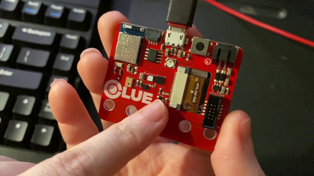
I am trying to get tensorflowlite running on Clue, I have seen lots of talk from 2019 onwards but little info. Is there a writeup?
I have wiped arduino and reinstalled to be sure old config gone
arduino compile errors galor
gilded gazelle
even trying different versions of arduino
gilded gazelle
<script src="https://pastebin.com/embed_js/1vwjvxFi?theme=dark"></script>
 lone ferry
That kind of looks like the TF example is broken.
livid osprey
proper wagon
What Bluetooth board or chip should I use for connecting 2 peco pis
Board or chip? If you fancy something capable of smt mounting, you can look for a non-s2 esp32 module or one of the nrf518/528 modules, like adafruit's 3320 or 4076. If you're thinking you might prefer a board, adafruit's bluefruit friends come in spi or uart flavors, or you can get another microcontroller board with Bluetooth enabled...
And if those options are all overkill for your application, other vendors should have more basic Bluetooth modules, as integrated Bluetooth chips and modules are getting more and more common
 pseudo mango
Hello. I connected the LC709203F LiPoly/Lion Fuel gauge https://www.adafruit.com/product/4712 with a feather 32u4 using Arduino code. I have a lipo 500mAh that measures 4.1x volts but the percentage shows 43% Am I missing something? Would the percentage be closer to 99%?

Low cost Lithium Polymer batteries have revolutionized electronics - they're thin, they're light, they can be regulated down to 3.3V and they're easy to charge. On your phone, ...
Oh, never mind. I had to reset the feather to correct itself
 deep steeple
So I'm trying to adjust the ESP32 BLE example code to work for a temp sensor server/client pair.
I have the client code here
client
and I have the reciever code here:
/*
    Based on Neil Kolban example for IDF: https://github.com/nkolban/esp32-snippets/blob/master/cpp_utils/tests/BLE%20Tests/SampleServer.cpp
    Ported to Arduino ESP32 by Evandro Copercini
    updates by chegewara
*/

#include <BLEDevice.h>
#include <BLEUtils.h>
#include <BLEServer.h>

// See the following for generating UUIDs:
// https://www.uuidgenerator.net/

#define SERVICE_UUID        "4fafc201-1fb5-459e-8fcc-c5c9c331914b"
#define CHARACTERISTIC_UUID "beb5483e-36e1-4688-b7f5-ea07361b26a8"

void setup() {
  Serial.begin(115200);
  Serial.println("Starting BLE work!");

  BLEDevice::init("Long name works now");
  BLEServer *pServer = BLEDevice::createServer();
  BLEService *pService = pServer->createService(SERVICE_UUID);
  BLECharacteristic *pCharacteristic = pService->createCharacteristic(
                                         CHARACTERISTIC_UUID,
                                         BLECharacteristic::PROPERTY_READ |
                                         BLECharacteristic::PROPERTY_WRITE
                                       );

  pCharacteristic->setValue("Hello World says Neil");
  pService->start();
  // BLEAdvertising *pAdvertising = pServer->getAdvertising();  // this still is working for backward compatibility
  BLEAdvertising *pAdvertising = BLEDevice::getAdvertising();
  pAdvertising->addServiceUUID(SERVICE_UUID);
  pAdvertising->setScanResponse(true);
  pAdvertising->setMinPreferred(0x06);  // functions that help with iPhone connections issue
  pAdvertising->setMinPreferred(0x12);
  BLEDevice::startAdvertising();
  Serial.println("Characteristic defined! Now you can read it in your phone!");
}

void loop() {
  pCharacteristic->getValue();
  delay(2000);
}
The issue I'm having is I'm not sure how to get the characteristic value that the client sets on the server side and google hasn't been much help.
 restive heath
Hey y'all, I havea Trinket M0 whcih just stopped ebing recognized by my Windows 7 machine,
I've unplugged, replugged the USB,
reset the Trinket M0 via the rest button, then unplugged & replugged the device via USB,
Did the same with the MicroUSB board portion,
Tried different USB ports,
Waited 30 seconds between plugs & replugs,
I've restarted my Windows machine,
I've restarted my IDE,
Disabled the Unknown Device, Reenabled the Unknown Device via Device Manager,
Uninstalled and then Reinstalled the adafruit_drivers_2.5.0.0 Trinket M0 drivers,
and the device is still an Unknown Device throwing a Code 43 error.
I let it run from 6am until 3:30pm,
and when I went to push new code, the Arduino IDE said nothing was on the COM12 port
And here we are.
Any other suggestions?


Hm.
Touching the RST pad seems to have resolved the issue.
This USB 'unresponsiveness' has happened a four times in the past 24 hours, and is getting progressively worse.
Am I doing something wrong?
stable forge
restive heath
Hm.
Touching the RST pad seems to have resolved the issue.
This USB 'unrespon...
if you are uploading with Arduino, the best thing to do is to double-click the reset button, so you get the pulsing red LED. Then make sure the Port menu has a checkmark on the correct port. Then compile and upload.
if just touching the pad is causing flakiness, do you have something wired to RST? Besides the sensor, is anything else wired to the board?
are your connections well-soldered, or are you using a breadboard?
restive heath
stable forge
if you are uploading with Arduino, the best thing to do is to double-click the r...
Touching the RST pad is what fixed the Code 43 error.
Touching the built-in Reset button ont he Trinket M0, just once, did not fix the issue.
Next time Code 43 pops up I will try the double-tap of the built-in Reset button.
There seems to be a line of code actually causing the issue, and that seems strange...
Serial.print("Time: " + micros());
After pushing code which has that line in the loop(), either:
the PC throws a Code 43 -- happened twice now,
or, right now, the COM port is busy - to be determined
commenting out the line, I just did 3 good code pushes, including printing Time + millis()
but Time + micros() seems to be FUBARing the hardware. Strange.
====
Just double-tapped the Reset button,
cleared up the busy COM port, reconnected to the PC just fine -- thanks 🙂
I also commented out the
Serial.print("Time: " + micros());
and successfully pushed code again.
restive heath
stable forge
if just touching the pad is causing flakiness, do you have something wired to RS...
Nothing wired tot he RST.
The Wearable channel has a photo of my wiring.
Nothing wired to the RST pad though; just touched it with some jumper to intentionally initiate a reset to troubleshoot that Code 43.
stable forge
if you just do Serial.print("Time: "); Serial.print(micros()); you will not end up concatenating string values.
restive heath
stable forge
are your connections well-soldered, or are you using a breadboard?
The only soldered connections are:
The 5050 LED to the breakaway PCB board, and

Male-to-Male Jumper wires soldered at the Velostat end; alligator clipped at the Ground && Pin 1~ connection
Pictures for reference:


alligator Velostat end, TO-BOARD

Trinket M0 wiring
 restive heath
stable forge
if you just do `Serial.print("Time: "); Serial.print(micros());` you will not en...
restive heath
stable forge
if you just do `Serial.print("Time: "); Serial.print(micros());` you will not en...
yeah, I'm new to Arduino/Electronics in general, but not new to programming, so some casting and similar built-in functions & syntax issues are cropping up from time to time. And that's ok. Just running into unexpected behavior as a result, but always learning. Reading the documentation as needed
  Serial.print("Time: ");
  Serial.println(millis());
  Serial.println("sensor = " );
  Serial.println(sensorValue);
edit: running code now pasted 🙂
is what I have now.
Millisecond intervals will also be easier to manage. I think at least
stable forge
I'd suggest soldering some headers onto the board. Alligator clips on small pads can be flaky. For prototyping, solder headers and then use a breadboard and the Dupont-style jumpers
restive heath
stable forge
I'd suggest soldering some headers onto the board. Alligator clips on small pads...
Solder these short-long headers, right?
Or something else -- (female headers soldered onto the board?)
 stable forge
yes, solder them as shown in the Trinket guide. But do you have a breadboard and/or M-F jumpers?
restive heath
I do have a breadboard, and M-F jumpers, yes
restive heath
np.
I'll re-home to the breadboard (is that what the recommendation is?)
stable forge
"home free" means there is no obstacle
I realized earlier you may be a native speaker of other than English
restive heath
Oh, haha, I'm English as a first language. Just trying to practice German where I can
restive heath
stable forge
anyway 🙂 <https://learn.adafruit.com/how-to-solder-headers/male-headers#solderi...
Oh man, putting the Trinket over the Center of the board, that's a good trick. Thanks Dan 🙂
stable forge
we have a Guide for every occasion
 hallow abyss
I need some help, I'm trying to use some Xbee radios in API mode and need to build a character string of hex values to send to the radio. As such, I need concatenate a bunch of these characters. I've been trying to use strcpy() and strcat() to do that, but reverted back to using a for() loop. I also need the length of the string (Not the entire array, that is already set), but strlen() won't work because I need to be able to include zeros in the string. I've figured out that the array has data that isn't reflected by strlen() because it stops at a null character (0). Is there some way around this? I can post my code.
 cedar mountain
Just to clarify, are you sending ASCII hex values like "8F", or raw bytes like 0x8F?
hallow abyss
0x8F
cedar mountain
In that case you'll need to keep a length count as you construct the string, since there's nothing in the string data itself which could tell you where it ends.
hallow abyss
so dynamic array length, i.e. the array = string + 1
cedar mountain
Why +1?
cedar mountain
If nulls are allowed to be embedded in the string, a null termination at the end doesn't make much sense.
hallow abyss
strlen() uses that null character]
I'm not sure how it works tbh
all I know is that if I have to use strcat() it needs that null character, which happens to be 0x00
cedar mountain
I'd assume the API would accept a pointer and a length as a parameter.
You don't want to use strcat(), for exactly that reason. It wouldn't be able to tell where the end of the string is. A direct for loop with array access is probably your best bet.
hallow abyss
I can increase the array size by 1 every loop, right?
cedar mountain
If you're copying in one byte at a time, yes.
Depending on where you're getting the data from, memcpy() may also be useful.
hallow abyss
 char init = 0x7E;
 char frmTyp = 0x10;
 char frmId = 0x01;
 char macAdd[] = {0x00, 0x13, 0xA2, 0x00, 0x41, 0xDE, 0xC6, 0x41};
 char add16[] = {0xFF, 0xFE};
 char brodRad = 0x00;
 char txOp = 0x00;
 char* data = input;
 char shortMessage[100];
 for (int i = 0; i<sizeof(macAdd); i++)
 {
  shortMessage[i]=macAdd[i];
 }
 Serial.println(strlen(shortMessage));
 //char chksum =
 //static char mssg[4] = {init};
 //return mssg;
}```that is the section of code I'm working with
cedar mountain
There's a number of things problematic about that. For one, shortMessage is actually an array of 100 Strings.
hallow abyss
shoot hang on
I changed it, sorry
I'm trying to stay away from the String() objects
cedar mountain
The other thing which will come up later is that you're probably going to be returning shortMessage to the caller, but it's a function-local variable which disappears when the function exits.
hallow abyss
so I need a string as a char array
no, actually, I need to find the length of shortMessage later to include bytes about the packet length.
cedar mountain
Ah, gotcha, never mind. Do you actually need to construct the string to know its length, or can you just do math from the length of the MAC address, etc.?
hallow abyss
except for init, I need to know the legth of everything up to shortMessage as a single array (Variable length because I will pass data into the function)
cedar mountain
Can the data being passed in include nulls?
hallow abyss
I assume so?
cedar mountain
In that case you'll need to pass in the length of the data too, since there's no way for the function to know from the data itself.
hallow abyss
yeah, that's the original problem. It's all char array data, so if I can figure out how to a: concat the arrays, and b: find their length, I can do it for all of them.
cedar mountain
That's an impossible task unless you want to make a lot of assumptions about the packet contents and structure. The lengths need to be tracked separately.
hallow abyss
maybe I could use the int data type to keep track of individual lengths
cedar mountain
Yes, you'd want to have an integer length variable which you pass around. Technically size_t might be more correct, but any int-like type is probably fine.
hallow abyss
could I pass ASCII (char string) as size_t data type?
cedar mountain
No, I meant the length variable itself. size_t is just an unsigned int of a range appropriate for array lengths on a given CPU architecture.
 cerulean knoll
skybird, wouldn't a more typical way to do this be to use a struct?
hallow abyss
cerulean knoll
skybird, wouldn't a more typical way to do this be to use a struct?
I'm not familiar with that
cerulean knoll
something like:
struct packet {
  uint8_t init;
  uint8_t frmTyp;
  uint8_t frmId;
  uint8_t[8] macAdd;
  uint8_t add16;
  uint8_t brodRad;
};
How would that solve the original problem?
cerulean knoll
sorry looking back in history here
hallow abyss
Your good. I would still have to reference each separate value I think.
cerulean knoll
well, first off, you can use memcpy instead of strcpy, if you want to copy a length of data rather than a null terminated string
(that's not related to the struct, just to solve your problem)
(maybe?)
hallow abyss
ok, is there a equivalent for concatenation?
Yeah, I think if I understand correctly, I would have to reference as such: packet.init, packet.frmType, etc.
cerulean knoll
uh, you would probably just change the start address for memcpy
cedar mountain
You can do pointer arithmetic for concatenation:memcpy(dest + destlen, source, length);
cerulean knoll
maybe ignore the struct for the moment
because the struct alignment may not be contiguous
saying you are using C strings instead of a String class or std::string is kinda setting off alarm bells though
cerulean knoll
a null terminated array
hallow abyss
staying away from String() because of efficiency
hallow abyss
hmm
cerulean knoll
but like, using fixed length buffers of char* is less offputting I think
hallow abyss
right now, I'm overallocating array length
cerulean knoll
(memcpy/memcmp, instead of strcpy/strcmp)
hallow abyss
cerulean knoll
(memcpy/memcmp, instead of strcpy/strcmp)
ok, now I'm still having trouble with strlen() returning a length of 0 if the first value in the array is 0
north stream
And that is the correct answer: a character array with the terminating null as the first character has a length of zero (null-terminated strings use one more byte than their length)
hallow abyss
north stream
And that is the correct answer: a character array with the terminating null as ...
the array length is 100, I preset it before I copied 0x00 into the first indice.
I know it isn't zero length because it still returns the correct data in indice 2
cerulean knoll
A "C string" (char*) is a chunk of memory that ends with 0
so all the "strXXX" functions deal with that
hallow abyss
char macAdd[] = {0x00, 0x13, 0xA2, 0x00, 0x41, 0xDE, 0xC6, 0x41};
cerulean knoll
the underlying array is (hopefully!) larger than the string length
but in that case, you need to store the length
hallow abyss
this needs to be a part of the array
cerulean knoll
you need to use memcpy then
I recommend you completely forget about the existence of any function starting with "str"
hallow abyss
...

char shortMessage[100];
memcpy(shortMessage,macAdd,8);
 Serial.println(strlen(shortMessage));//Returns 0
Serial.println(shortMessage[2]);// Returns decimal eq. of 0x13```the str functions are intended for textual data, and you have binary data
cerulean knoll
I don't know that there's any real problem using char as the data type, but think of it a "byte" instead of "char"
hallow abyss
But I'm not sure how to achieve what I need with byte arrays either
cerulean knoll
that's why I used uint8_t in my example
well we can figure that out!
what's the overall goal here?
you have a message you want to send over xbee?
hallow abyss
send a string (array) of hex (binary) data to the Xbee. I need to be able to concatenate and know lengths of arrays to do this. I need to also calculate a checksum using the array.
hallow abyss
yes, it is documented very well by Digi, I have the user guide
it is too much to fit here, but I can link the doc and reference the page
 cerulean knoll
it is difficult stuff to understand at first!
but when you get it, it will make a lot of sense
hallow abyss
I hope so lmao
cerulean knoll
so, what I'd do is create a struct:
struct TxReqHeader {
  uint8_t startDelim;
  uint8_t len[2];
  uint8_t frameType;
  uint8_t frameId;
  uint8_t dstAddr[8];
  uint8_t reserved[2];
  uint8_t bRadius;
  uint8_t txOptions;
} __attribute__((packed));
__attribute__((packed)) tells GCC (the compiler) not to pad the struct according to the typical rules
Then
uint8_t payload[MAX_PAYLOAD_LEN];
size_t payloadLen;
uint8_t checksum;
do I put that inside the struct
cerulean knoll
no
hallow abyss
also, the array brackets throw errors if they are before the declared name
cerulean knoll
doh
should be fixed
then fill out that struct with your data
then fill out the payload, and set the payload length
(actually, to see the length in the header you will need to know the length of the payload)
hallow abyss
cerulean knoll
(actually, to see the length in the header you will need to know the length of t...
exactly
cerulean knoll
that's not a problem though, is it?
I mean, you have to know the payload you're going to send
hallow abyss
yeah, but that got me into this whole mess in the beginning
that is what I have bee trying to do all day
the two length bytes account for everything between them and the checksum.
hallow abyss
yeah, 0x0E + payload length
gilded gazelle
lone ferry
That kind of looks like the TF example is broken.
could it need an older version of something? I already know not to use current TFLite
cerulean knoll
hallow abyss
yeah, 0x0E + payload length
I guess I'm not seeing the problem (apologies if I'm being dense here)
if you know the payload length, you know how to fill out the header
hallow abyss
cerulean knoll
I guess I'm not seeing the problem (apologies if I'm being dense here)
Your fine, I put the struct into a function that I now need to pass the data into.
hallow abyss
cerulean knoll
if you know the payload length, you know how to fill out the header
  uint8_t payload[strlen(data)] = data;
  size_t payloadLen = strlen(data);
  uint8_t checksum;
  struct txReqheader {
    uint8_t startdelim = 0x7E;
    uint8_t len[2] = 0x0E + payloadLen;
    uint8_t frameTyp = 0x10;
    uint8_t frameId = 0x01;
    uint8_t macAdd[8] = { 0x00, 0x13, 0xA2, 0x00, 0x41, 0xDE, 0xC6, 0x41 };
    uint8_t reserved[2] = { 0xFF, 0xFE };
    uint8_t brodRad = 0x00;
    uint8_t txOp = 0x00;
  } __attribute__((packed));
}```I hope this is on the right track
@cerulean knoll thanks for your help btw
cerulean knoll
np! does that compile?
hallow abyss
not quite
cerulean knoll
Usually you would define the struct outside the function
but set the value inside the function
I'll do an example a sec
hallow abyss
also, I rearanged the order so that it wouldn't throw an error for payloadLen not being declared
cerulean knoll
struct TxReqHeader {
  uint8_t startDelim;
  uint8_t len[2];
  uint8_t frameType;
  uint8_t frameId;
  uint8_t dstAddr[8];
  uint8_t reserved[2];
  uint8_t bRadius;
  uint8_t txOptions;
} __attribute__((packed));

byte xbeeString(char input[]) {
  uint8_t payload[strlen(data)] = data;
  size_t payloadLen = strlen(data);
  uint8_t checksum;
  TxReqHeader header;
  header.startdelim = 0x7E;
  header.len = 0x0E + payloadLen;
  header.frameTyp = 0x10;
  header.frameId = 0x01;
  header.macAdd = { 0x00, 0x13, 0xA2, 0x00, 0x41, 0xDE, 0xC6, 0x41 };
  header.reserved = { 0xFF, 0xFE };
  header.brodRad = 0x00;
  header.txOp = 0x00;
}
I didn't rename the fields to match each other
but hopefully the idea is clear
hallow abyss
oh oh oh
cerulean knoll
now you realize if the payload has any 0s in it, you're gonna have an issue?
hallow abyss
the actual payload will be the hex for ASCII characters, so I should be ok there
cerulean knoll
ok
hallow abyss
cerulean knoll
ok
error: assigning to an array from an initializer list
header.reserved = { 0xFF, 0xFE };
^
cerulean knoll
uh, I guess you can't do that. You could break it out into header.reserved[0] = 0xFF; and header.reserved[1] = 0xFE;
or you could make a separate array using the initializer list, and use memcpy to copy them
(this might be less tedious for the mac address)
also I can't remember the endianness
if it should be [0] = 0xFE [1] = 0xFF, or vice versa
hallow abyss
cerulean knoll
also I can't remember the endianness
big endian
for multi byte values
they should already be in the proper order
 hollow flint
hey everyone: I'm trying to use adafruit:samd in arduino-cli on a raspberry pi (using raspi-os 64 bit) and I run into this error when installing the core
Tool arduino:bossac@1.7.0-arduino3 already installed
Tool arduino:openocd@0.10.0-arduino7 already installed
Tool arduino:arduinoOTA@1.2.1 already installed
Downloading packages...
adafruit:arm-none-eabi-gcc@9-2019q4 already downloaded
Error during install: tool arduino:bossac@1.8.0-48-gb176eee not available for the current OS
this works without issue on mac os 11.3.1
hallow abyss
@cerulean knoll sorry to bother you again.
   header.len = 14 + payloadLen;
^~~~~~~~~~```I did some searching and couldn't figure out how to fix this
north stream
header.len = (uint8_t) (14 + payloadLen);
cerulean knoll
oh actually header.len is 2 uint8s
north stream
Ah, you'll have to either use a union or split it up explicitly
cerulean knoll
you might be able to make it a uint16, I haven't thought much about the endianness
north stream
You may be able to use sizeof(struct TxReqHeader) instead of 14
cerulean knoll
it's actually not the entire size of the TxReqHeader
there's probably a more elegant way to express it
north stream
Ah, can't use that dodge. In that case, I'd probably #define it to something to make it clearer
cerulean knoll
but there's a frame, and it's the size of the frame
cerulean knoll
spoiler alert: this all ends with you casting the struct to a char* and writing it out 8 bytes at a time for sizeof() the struct
(and then doing the payload and checksum)
hallow abyss
I abandoned this effort and am trying to get the old xbee library from andrew rapp to work. I'm surprised by the lack of modern help for series 3 xbee radios.
 junior basin
I'm trying to claw my way up the tool chain to do Arduino development on a new ATSAMD21E pcb design. I find myself needing to review the boot logs using openocd -- has anyone gotten the J-Link Mini to work with Mac? It seems like a driver is needed.
cerulean knoll
hallow abyss
I abandoned this effort and am trying to get the old xbee library from andrew ra...
his name is 2 letters off from mine, so let me know if this doesn't work
more seriously, I'd like to see your project work 🙂 and it seems like it should be doable
i am not really up to date on xbee, is "series 3" old hw?
lone ferry
gilded gazelle
could it need an older version of something? I already know not to use current T...
I don't know. It's been a while since I used TFLite on Arduino (and I didn't use the Clue).
hallow abyss
cerulean knoll
i am not really up to date on xbee, is "series 3" old hw?
No, it's the newest series. It seems this library is possibly out of date, however, it was what Digi had on their website.
gilded gazelle
lone ferry
I don't know. It's been a while since I used TFLite on Arduino (and I didn't use...
@daring marsh has a 60sec video of it working but I cant find any record of what she did
going through another uninstall and wipe of Arduino trying to get TF Lite to compile
 tired gazelle
Hey there, I have a pretty simple question, and its probably extremely easy and im just dumb but like
im doing this project where im reading temperature and humidity data
I want to make something where if I have 5 consistent readings every 30 seconds that output a temperature over or below a certain threshold, it prints something to serial about it. Is there a specific way I should do that?
do I do something as simple as an array?
 leaden ruin
You want a thermostat with hysteresis? Seems like a pair of counters would do it. Increment each time you read something too high.
Reset the counter when the reading is below the threshold.
 odd fjord
@tired gazelle Do you want to save the data or just raise an alarm? You can just set a counter that increments every time the threshold is exceeded and is cleared if it is not. If the counter reaches your maximum number -- raise your alarm.
tired gazelle
odd fjord
<@!195171623148584962> Do you want to save the data or just raise an alarm? You ...
raise an alarm. I made a counter, I got that working already. It sends a warning message when it reaches 5 and I have an if statement to increment if it goes above
However, now what Im trying to figure out is how to determine that its within the same time period
      {
        tempThreshCheck++;
      }
      if (tempThreshCheck==5)
      {
        Particle.publish("warning","Temperature has exceeded temperature threshold");
      }
```this is the very simple code I have
odd fjord
ah -- so you can save the time when tempThreshCheck==1 and then again when it hits 5 and compare the times.
tired gazelle
would I just save the millis()?
odd fjord
That should be fine
tired gazelle
ok
Ive never worked with arduino stuff before so im not too familiar with some of the basics lmao. Idk if certain things are supposed to act a certain way
odd fjord
It looks like you are off to a good start.
tired gazelle
actually though
millis counts the overall time the program is running right?
this one website says "If you waited 7 days, the value “returned” would be 604,800,000 (7 days x 24 hours x 60 min x 60 secs x 1000 ms)."
odd fjord
You aloo should clear your counter if it is not being incremented.
tired gazelle
yeah I planned to do that
tired gazelle
tired gazelle
this one website says "If you waited 7 days, the value “returned” would be 604,8...
so considering that, if this device was running 24/7 (because it would be) wouldnt it eventually return a bigger number than it might be able to handle?
odd fjord
      {
        tempThreshCheck++;
        if(tempThreshCheck == 1)
        {
           start_time = millis();
        }
      }
      else
      {
        tempThresCheck = 0;
      }
      if (tempThreshCheck==5)
      {
        if(millis() - start_time > 5000)
        {
            Particle.publish("warning","Temperature has exceeded temperature threshold");
        }
      }
``` something like thisactually though, its not being stored. so im dumb lol
or well, it is with start_time. but thats gets reinitialized every time its called
im just concerned that number would eventually be really big. I know it can take up to like 4 billion bytes or something but if its on for a very long time would that eventually be something harmful
odd fjord
see this discussion https://arduino.stackexchange.com/questions/12587/how-can-i-handle-the-millis-rollover it looks like millis() "rolls over" after about 49 days.
tired gazelle
oh nice. thats probably enough time
odd fjord
You can handle that in your code by checking if the end time is less than the start_time
odd fjord
You're welcome -- There are many ways to accomplish the same thing, so experiment. Good luck with your project.
tired gazelle
thanks, I appreciate it
lone ferry
gilded gazelle
<@340718517408104450> has a 60sec video of it working but I cant find any record...
I used it about 3 or 4 months ago on my Arduino Nano 33 BLE Sense, but that's also one of the officially supported boards for TFLite Micro.
gilded gazelle
lone ferry
I don't know. It's been a while since I used TFLite on Arduino (and I didn't use...
progress, hello_world_arcada example WORKED
however I get the following when trying micro_speech_arcada example
C:\Users\aalha\AppData\Local\Temp\arduino_modified_sketch_517247\arduino_audio_provider.cpp: In function 'void CaptureSamples()':
arduino_audio_provider.cpp:180:33: error: 'DEFAULT_BUFFER_SIZE' was not declared in this scope; did you mean 'SERIAL_BUFFER_SIZE'?
180 | const int number_of_samples = DEFAULT_BUFFER_SIZE;
lone ferry
Does the CLUE come with a digital microphone, @gilded gazelle ?
Because the DEFAULT_BUFFER_SIZE definition belongs to the microphone library (PDM).
gilded gazelle
lone ferry
I used it about 3 or 4 months ago on my Arduino Nano 33 BLE Sense, but that's al...
yes
gilded gazelle
lone ferry
Because the `DEFAULT_BUFFER_SIZE` definition belongs to the microphone library (...
has a mic
lone ferry
Yeah but is it the mic that the TFLite example expects?
gilded gazelle
I will look there, thank you for pointer
gilded gazelle
lone ferry
Yeah but is it the mic that the TFLite example expects?
yup PDM on different pins, where should I look for those assignments?
lone ferry
You'd need to see if the TFLite code or the example project is actually including the PDM library.
So on the Arduino that happens in this file: https://github.com/tensorflow/tflite-micro/blob/main/tensorflow/lite/micro/examples/micro_speech/arduino/audio_provider.cc
But for your device, it may be using a different audio_provider.cc
Hmm, it looks like you're using an older version of the code.
lone ferry
It's also amazing that my bug fixes for this example didn't actually make it into the new tflite-micro repo.
gilded gazelle
not micro_speech

Adafruit Learning System
Try TensorFlow Lite with Circuit Playground Bluefruit
Adafruit Industries - Makers, hackers, artists, designers and engineers!
Testing out the TensorFlow micro speech demo on Adafruit CLUE (video). Only took us a few minutes to compile our TF Lite micro demo from the Circuit Playground Bluefruit over onto the CLUE board. I…
@daring marsh did it....somehow
zeropdm is in an #IFDEF
but there isnt an #IFDEF for the clue and I have no idea what should be in one
for the different board
trying examples from PDM lib ....lets see
NOPE
'Adafruit_ZeroPDM' does not name a type; did you mean 'Adafruit_ZeroDMA'?
@lone ferry
lone ferry
I don't know what to use for the CLUE.
 safe halo
Hello I am trying to get the Adafruit MPU6050 library to read an MPU5060 however even with the examples I cannot get it to find the sensor. I have the following pins on my ESP32 mapped: SDA = 21, SCL = 22, RST = 16.
However
  if (!mpu.begin())
  {
    Serial.println("Failed to initialize sensor");
    while (1)
    {
      delay(10);
    }
  }
  else
  {
    Serial.println("MPU6050 Found!");
  }
Always fails to connect.
 gilded gazelle
I basically replaced audio_provider.cpp with the one from the non-ada example
I removed all the IFDEF and let PDMlib sort it out
leaden walrus
@safe halo try running this i2c scanner sketch and see if the MPU can even be seen. it should report back its address:
https://playground.arduino.cc/Main/I2cScanner/
safe halo
leaden walrus
<@!531135983048065034> try running this i2c scanner sketch and see if the MPU ca...
Found the device, now need to figure out why the Library wont find it...
leaden walrus
Adafruit MPU6050 library to read an MPU5060 just a typo in second part? you're using one of these?
https://www.adafruit.com/product/3886
safe halo
Similar but not the same.
https://amzn.to/3hP7cy7
MPU-6050 Module, 3-axis Gyroscope and 3-axis Accelerometer/Acceleration Sensor/Tilt Sensor, I2C, e.g. for Arduino, Genuino, Raspberry Pi: Amazon.co.uk: Business, Industry & Science
livid osprey
Well, it's definitely an MPU6050, and not a 5060.
leaden walrus
what address did it report back with the i2c scan?
safe halo
0x68
leaden walrus
ok. library uses that as default.
not sure. the begin() call checks device id:
https://github.com/adafruit/Adafruit_MPU6050/blob/86e65d01e5dc4529d4f8a362f491949c322fb1df/Adafruit_MPU6050.cpp#L70
could maybe add some serial.prints to the library code in begin() and print what it returns
safe halo
Im loading the mpu6050_unifiedsensors.ino from the library now and seeing what it comes back with.
Still failed.
leaden walrus
what did it come back with? what actual device id was returned? you'd need to edit the library code to get that. not just sketch code.
safe halo
 leaden walrus
right. but, what was the value?
https://github.com/adafruit/Adafruit_MPU6050/blob/86e65d01e5dc4529d4f8a362f491949c322fb1df/Adafruit_MPU6050.cpp#L86
safe halo
I added Serial.println( chip_id.read()); and it came back with 152
Changed it to
Serial.println( chip_id.read(), HEX);
and got back 98
leaden walrus
must be a different chip or something. the expected chip id is 0x68:
https://github.com/adafruit/Adafruit_MPU6050/blob/86e65d01e5dc4529d4f8a362f491949c322fb1df/Adafruit_MPU6050.h#L28
safe halo
Its weird because that is what is showing when I do the I2C Scan.

 brazen galleon
what is diff between 3 pin and 4 pin thermistor module?
leaden walrus
"module"? so it's not just a bare thermistor?
brazen galleon


they are same but one has extra pin A0 and its somewhat more expensive compared to other
leaden walrus
hmm. not sure. but something related to the interface to the microcontroller. like just two different options.
brazen galleon
lol ldr module has all same components and same board
ig bcuz both ntc thermistor and ldr works (change resistance)
leaden walrus
looks like maybe it's setup to be a digital switch? for theDO output.
set some level with the pot, then DO is either 0 or 1 depending on level
brazen galleon
the extra oin is named A0
leaden walrus
and maybe for the other one A0 gives you an actuall analog out?
brazen galleon
donno
im new to all this things
just adding parts in cart to get a full arduino kit..bcuz its way cheaper than readymade kits

leaden walrus
yah, i'm just guessing also. but a basic thermistor sensor is just a variable resistor. it's the little blob sticking off the other end with two wires.
brazen galleon
yes
 brazen galleon
aah yes
analog means itll be direct bypaas to thermistor right?
like direct thermistor attached
to arduino
leaden walrus
probably not direct, since you need something to turn variable resistance in to some kind of analog out
 worn palm
Hey all. I'm having a fun little problem with a Neopixel strip (1/4 60 Ring - 5050 RGBW) I'm controlling using a Feather M0. Everything works perfectly, including color changes, brightness changes, individual settings for each pixel, etc. But if I turn the brightness of the strip down to 0, it becomes unresponsive until I hit reset on the feather.
I'm initializing the strip as follows
#define NEOPIXEL        11
#define NUMPIXELS       15
Adafruit_NeoPixel pixels(NUMPIXELS, NEOPIXEL, NEO_GRBW + NEO_KHZ800);

void setup() {
  pixels.begin();
  pixels.setBrightness(128);
  for (int i = 0; i < NUMPIXELS; i ++) {
    pixels.setPixelColor(i, pixels.Color(255, 255, 255));
  }
  pixels.show();
}
If I were to then run
pixels.setBrightness(0);
pixels.show();
delay(20);
pixels.setBrightness(128);
pixels.show();
They won't come on again after that first setBrightness(0). Even stranger is that the strip test example that comes with the Neopixel library works perfectly, and includes bringing brightnesses down to zero and back up again. I'm missing something fundamental here, but I can't put my finger on it.
(Also, I'm new and this is my first time reaching out, so if this is the wrong channel or format for asking a question like this let me know!)
leaden walrus
can you post complete code of most simple case that shows issue
it may be context related - i.e, how and where you are calling pixels.setBrightness(0); in your specific sketch
worn palm
Sure thing
void setLedBrightness(char * brightnessString) {
  int brightness = atoi(brightnessString);
  brightness = map(brightness, 0, 100, 0, 255);
  int numSteps = 50;
  double increment = (brightness - currBrightness) / numSteps;

  for (int i = 0; i < numSteps; i ++) {
    pixels.setBrightness(currBrightness + (increment * i));
    pixels.show();
    delay(10);
  }

  //explicitly set pixels to the final brightness after animation, since the map() function above does some rounding
  pixels.setBrightness(currBrightness);
  pixels.show();
}
currBrightness is a global variable tracking the current brightness of the overall strip. I should probably be using getBrightness() there...
Oh also, a few more points about this code– it's taking a char * because it's meant to take user input through google assistant -> ifttt -> AdafruitIO. So passing '0' to this function will make the strip fade to off and never come on again until the feather is reset
leaden walrus
so that all works as expected until you pass in a brightnessString that tries to set 0?
worn palm
yes
But the previous sequence of setBrightness() and show() calls causes this issue as well
leaden walrus
so this doesn't work?
#define NEOPIXEL        11
#define NUMPIXELS       15
Adafruit_NeoPixel pixels(NUMPIXELS, NEOPIXEL, NEO_GRBW + NEO_KHZ800);

void setup() {
  pixels.begin();
  pixels.setBrightness(128);
  for (int i = 0; i < NUMPIXELS; i ++) {
    pixels.setPixelColor(i, pixels.Color(255, 255, 255));
  }
  pixels.show();
}

void loop() {
  pixels.setBrightness(0);
  pixels.show();
  delay(20);
  pixels.setBrightness(128);
  pixels.show();
}
Just ran that in a dedicated sketch and no dice 😔
I added a delay of 3 seconds at the end of the setup function to see that they initialized properly to begin with. They did, but then just shut off when the loop starts.
I hope I didn't bust the hardware somehow
leaden walrus
weird. which specific feather m0 is it?
worn palm
Adafruit Feather M0 WiFi - ATSAMD21 + ATWINC1500
Wait... I should check that I'm not using any pins needed by the wifi module. Could they be conflicting?
Nah they're all unique
leaden walrus

yep. spi pins are shared. but the few digital pins used are specific to the module.
is this with all latest libraries and board support pacakces? i can try and repeat issue here.
leaden walrus
doesn't look like i have that specific feather and neopixel hardware
but if it's a software issue, should happen with any m0
i can match that
worn palm
I have some packet radio feathers I can try to reproduce with out of curiosity, but I need the wifi module for this project
leaden walrus
that'd be a good sanity check though
heavy star
What is this "sanity" of which you speak?
worn palm
same issue??
leaden walrus
this works:
#include <Adafruit_NeoPixel.h>

#define NEOPIXEL        11
#define NUMPIXELS       15
Adafruit_NeoPixel pixels(NUMPIXELS, NEOPIXEL, NEO_GRBW + NEO_KHZ800);

void setup() {
  pixels.begin();
  pixels.setBrightness(128);
  for (int i = 0; i < NUMPIXELS; i ++) {
    pixels.setPixelColor(i, pixels.Color(255, 255, 255));
  }
  pixels.show();

  delay(1000);
}

void loop() {
  pixels.setBrightness(1);
  pixels.show();
  delay(500);
  pixels.setBrightness(128);
  pixels.show();
  delay(500);
}
one sec...gonna modify that slightly...
worn palm
worked properly?
I just ran the sketch you had send me on my radio feather and it also caused the lights to stop working
leaden walrus
ok. there. that works and runs as expected.
1 second of initial white. then it blinks forever.
change
pixels.setBrightness(1);
to
pixels.setBrightness(0);
and the loop no longer runs
worn palm
right! i have that exact same behavior. The loop is running, the LEDs just aren't responding. I'm still getting output from serial in the loop
worn palm
Interesting.... so maybe brightness should be adjusted using setPixelColor?
I understood that whole note except for the last sentence
leaden walrus
it looks like the library essentially 0's out the color info when you set brightness 0
so when you try to scale it back up, with brightness != 0, it can't recover the color info
worn palm
So I might be better off creating a 'color' string of "f000000" and using that as my 'off'
leaden walrus
for example, this works:
#include <Adafruit_NeoPixel.h>

#define NEOPIXEL        11
#define NUMPIXELS       15
Adafruit_NeoPixel pixels(NUMPIXELS, NEOPIXEL, NEO_GRBW + NEO_KHZ800);

void setup() {
  Serial.begin(9600);
  while (!Serial);

  pixels.begin();
  pixels.setBrightness(128);
  for (int i = 0; i < NUMPIXELS; i ++) {
    pixels.setPixelColor(i, pixels.Color(255, 255, 255));
  }
  pixels.show();

  delay(1000);
  Serial.println("Looping!");
}

void loop() {
  Serial.print(".");
  pixels.setBrightness(0);
  pixels.show();
  delay(500);
  pixels.setBrightness(128);
  for (int i = 0; i < NUMPIXELS; i ++) {
    pixels.setPixelColor(i, pixels.Color(255, 255, 255));
  }
  pixels.show();
  delay(500);
}
yah, try using fill()
worn palm
Check it out! This work:
#include <Adafruit_NeoPixel.h>

#define NEOPIXEL        11
#define NUMPIXELS       15
Adafruit_NeoPixel pixels(NUMPIXELS, NEOPIXEL, NEO_GRBW + NEO_KHZ800);

void setup() {
  pixels.begin();
  pixels.setBrightness(128);
  for (int i = 0; i < NUMPIXELS; i ++) {
    pixels.setPixelColor(i, pixels.Color(255, 255, 255));
  }
  pixels.show();

  delay(1000);
}

void loop() {
  pixels.fill(pixels.Color(0, 0, 0));
  pixels.show();
  delay(500);
  pixels.fill(pixels.Color(128, 128, 128));
  pixels.show();
  delay(500);

  Serial.println("Test");
}
^^ yep
worn palm
Ah you beat me to it
Ok. I actually built a function to 'fade' between colors. So I can just use it to fade to off. And problem is solved.
Thank you so much
leaden walrus
cool. np.
 blazing crane
I'm using a NEMA17 stepper motor to run a claw. The stepper motor runs well (when it works, that is), but is inconsistent. It occasionally gets jammed or isn't as responsive as I'd like, although I'd more so boil those down to hardware issues (but I could be wrong). The main problem I'm experiencing is that the motor is constantly vibrating and running, even if I've told it to sit still. The best way I'd describe it is it has a "goal position" that it's trying to get to, but overshoots by 1, then tries to go back and overshoots the other way; the end result being it twitching back and forth. I don't know that's what's actually occurring, but it's a good way to picture the issue.
The code is running on an Arduino Uno and an Adafruit Motor Sheild V1.
Any help is appreciated,
-Zman
#include <AFMotor.h>
#include <AccelStepper.h>

 AF_Stepper motor(200, 1);
 int msg;

 void forwardstep() {
   motor.onestep(FORWARD, SINGLE);
 }

 void backwardstep() {
   motor.onestep(BACKWARD, SINGLE);
 }

 AccelStepper stepper(forwardstep, backwardstep); // use functions to step

 void setupMotor() {
   stepper.setMaxSpeed(900);
   stepper.setAcceleration(900);
 }

 void setup(){
   Serial.begin(9600);
   setupMotor();
 }

 void loop(){
   if (Serial.available() > 0) {
     msg = Serial.read();
   }

   if (msg == 1) {
     stepper.setSpeed(900);
     //stepper.runSpeed();
   }

   else if (msg == 2) {
     stepper.setSpeed(-900);
     //stepper.runSpeed();
   }
   else {
     stepper.setSpeed(0);
   }

   stepper.runSpeed();
   //stepper.setCurrentPosition(0);
}```The issue seems consistent with that of improper wiring, but coil 1 is hooked up to M3+/-, and coil 2 is on M4+/-. Not sure where the wiring issue could be...
worn palm
@blazing crane forgive me if you've found this already, but this post/ thread seems to reference a similar problem, albeit with a different stepper motor. There isn't a super clear answer here, but there are some interesting diagnostic options to make sure the motor itself is in working order.
https://forum.arduino.cc/t/stepper-motor-moving-back-and-forth/309809/7

Arduino Forum
corrieuys: The problem I'm having is the motor moves a step in 1 direction, and then the next step in the opposite direction. Usually that means one of the windings isn't getting power. Power down, disconnect motor, test the resistance of each winding to make sure they are undamaged. Reconnect, double check all the connections with a mult...
blazing crane
@worn palm it appears the people in the thread solved the issue with a new motor. I've already tried multiple motors
safe halo
Anyone know how to add a board to platformIO that isn't listed?
 wraith current
@safe haloi don't but unexpected maker probably does. he has his own discord on which you can ask him.
 frank linden
@safe halo I have added some unlisted Sparkfun boards to PlatformIO, but they were SAMD51 based boards so it was just modifying some of the configuration files, as that core already has good support in PIO. If you are doing something like that I may be able to offer some advice, but if you are adding a completely or mostly custom board, I won't be too much help.
 pallid steppe
Any board which can record audio from aux?
livid osprey
A 3.5mm line out? Something like this? https://www.adafruit.com/product/1381

This breakout board is the ultimate companion for the VLSI VS1053B DSP codec chip. The VS1053 can decode a wide variety of audio formats such as MP3, AAC, Ogg Vorbis, WMA, MIDI, FLAC, WAV ...
 shrewd wyvern
Hi guys.. anyone know if I can control 2 different strips of neopixels using the adafruit library on a Arduino Nano Every
I know it is not supposed and it may have some glitches but the lights won't change often
north stream
I'm not sure, but I think so. The library only sends data when you call show()
shrewd wyvern
do you think I can instance 2 objectS?
I remember that there were some timings constrains
I'll give it a try and report back
vivid rock
FastLED supports several strips in parallel, but it seems it only does that on selected boards:
https://github.com/FastLED/FastLED/wiki/Parallel-Output
 formal onyx
Im using a line sensor with 8 LEDs on it. It seems to be working as expected, except that the leftmost LED (0 in the array) isn't changing- it's always 1. https://pastebin.com/jXCwvS0p I'm not the most experienced programmer, is there something obvious that I've done wrong?
Pastebin
Pastebin.com is the number one paste tool since 2002. Pastebin is a website where you can store text online for a set period of time.
Thinking the issue might be pin 1, I changed it to pin 9 and updated my code accordingly https://pastebin.com/sZTPUdaR
Pastebin
Pastebin.com is the number one paste tool since 2002. Pastebin is a website where you can store text online for a set period of time.
stable forge
formal onyx
Thinking the issue might be pin 1, I changed it to pin 9 and updated my code acc...
C arrays are indexed starting at 0, so
for (int i=1; i<9; i++){
@formal onyx for an array of 8 elements, index i ranges from 0 to 7
stable forge
should be for (int i=0; i<8; i++){
formal onyx
Okay thank you guys, with that they're all changing now.
 stoic vessel
Hello everyone, I'm seeking help with my adafruit trellis project with arduino, if anyone can help. I've been using the Untztrument and Arduino Trellis example code to test my work. Whenever I connect one trellis by itself, it works perfectly, but when I have two connected to each other, I get very strange behaviour (leds lighting up randomly and the buttons don't work.) if anyone could look at my code and I could send pictures of my trellis too, that would be amazing!
 pine bramble
@stoic vessel Trellis is a branding but I think the technology underlying it has changed over the years.
It's always a silicone keypad.
 old heart
Whats the easiest way to add extra power to a servo in an Arduino project? I'm powering my sensor with the arduinos 5v but everytime the servo moves, the lights on the sensor flicker messing up results.
I tried looking it up but I couldn't find anything I could really understand
Though right now I have it powered from a USB plugged into my computer, if I move to a 9v will that fix it?
vivid rock
most servos are only rated for voltage up to 7.2v, some only up to 6v. Feeding them 9v can damage them
old heart
I mean like powering the arduino with a 9v, then using the 5v from the arduino
vivid rock
no
5v output from arduino is very limited in current, and feeding it higher voltage will not change that
old heart
Okay, so how do I add external power to the servo then?
vivid rock
you need a separate 5v power supply capable of producing decent current - at least 2A
you only have one servo? what kind/size?
 vivid rock
microservo
old heart
yea that
vivid rock
then indeed you don't need much current, 1A should be more than enough
old heart
Okay, and how do i feed that to the servo without going through the adruino?
vivid rock
servo has 3-wire connector: gnd, 5v, signal
connect gnd to arduino ground and also to negative of power supply, 5v to positive of power supply, and signal, to an arduino pin
and then you can power arduino from same power supply,or from USB
old heart
Okay, thank you!
 molten kernel
Hello, I've got some code that works, But I'd like to know if there is a cleaner more sophisticated way of writing it..
I'm still very new to Arduino and Individually Addressable LED's
void loop() {
  // Set Pixel 0 + 1 to Red.
  for (int i=0; i < 2; i++) {
    pixels.setPixelColor(i, pixels.Color(255,0,0));
  }

  // Set Pixel 2 + 3 to Blue.
  for (int i=2; i < 4; i++) {
    pixels.setPixelColor(i, pixels.Color(0,0,255));
  }
  // Update Pixels to show new colors.
  pixels.show();
  // Use delayval to determine flash speed.
  delay(delayval);

  // Set Pixel 0 + 1 to Blue.
  for (int i=0; i < 2; i++) {
    pixels.setPixelColor(i, pixels.Color(0,0,255));
  }

  // Set Pixel 2 + 3 to Red.
  for (int i=2; i < 4; i++) {
    pixels.setPixelColor(i, pixels.Color(255,0,0));
  }

  // Update Pixels to show new colors.
  pixels.show();
  // Use delayval to determine flash speed.
  delay(delayval);
  }
sure, could do it differently, but would want to consider things like - do you want to allow for more than 4 pixels? allow for more than 2 colors? etc.
also, if you are just starting out, try not to worry too much about making code fancy. i think having fun and getting it to do what you want is more important.
void setup() {
  //
  // other setup stuff
  //

  uint32_t color1 = pixels.Color(0,0,255);
  uint32_t color2 = pixels.Color(255,0,0);
  uint32_t colorSwap;
}

void loop() {
  pixels.setPixelColor(0, color1);
  pixels.setPixelColor(1, color1);
  pixels.setPixelColor(2, color2);
  pixels.setPixelColor(3, color2);

  pixels.show();
  delay(delayval);

  colorSwap = color1;
  color1 = color2;
  color2 = colorSwap;
 }
A goofy (if weird, complicated, and confusing) approach: ```arduino
unsigned long next;
int phase;
void loop() {
int i;
int sel;
unsigned long now = millis();
if (now > next) {
next = now + delayval;
for (i = 0; i < 4; ++i) {
  sel = phase ^ !(i & 2);
  pixels.setPixelColor(i, pixels.Color(!sel * 255, 0, sel * 255));
}

phase = !phase;
pixels.show();
}
}
 paper oracle
https://i.imgur.com/UToAvMY.png
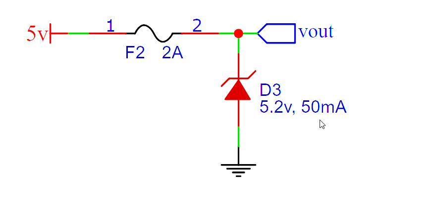
Not sure its quite the right place but... Want to provide some overvoltage protection after 24v -> 5v buck converter with ~1a load without going as far as adding a crowbar circuit. 50mA zener is obviously under rated for the 10's of amps the 24v can supply but, since as far as I know they fail short, will this be cheap and easy insurance?
 deep steeple
Is there a limit to the length of a Strip in the neopixel library? I have a length of 360 neopixels (split between 2 power supplies grounded properly etc.) but when I try to do over 275 in length they don't work. Is this just not possible?
Upon googling looks like there is no limit so would anyone have some ideas as to why it may stop working about that number? I can share the code if it would help
I am using the rainbow code is the issue possibly I'm going over the valid color values which may be breaking the code?
void rainbow2(uint8_t color) {
  uint16_t i;
    for(i=0; i<275; i++) {
      lamp.setPixelColor(i, Wheel((i*1+color) & 255));
    }
    lamp.show();
}
Each pixel will take up some memory, so if you have a relatively low-RAM board like an Uno, you might run into problems there. When you say it "doesn't work", what's the actual problem?
deep steeple
cedar mountain
Each pixel will take up some memory, so if you have a relatively low-RAM board l...
There is simply no light from the pixels and I'm running it on an arduino nano
The second strip I'm also running off another pin functions as normal and based on my math at least seems I should have enough sram
cedar mountain
The compiler should print out some stats on memory usage, so you can verify how much RAM it thinks you have available.
deep steeple
Sketch uses 8486 bytes (27%) of program storage space. Maximum is 30720 bytes.
Global variables use 590 bytes (28%) of dynamic memory, leaving 1458 bytes for local variables. Maximum is 2048 bytes.
and based on my math the two IO pins I'm running strips off of should use around 1.4 bytes so I guess that may be the issue
I'll try reuploading the code without the second pin lights
So I've not tried even using the strand test so no other lights are being used at all which got it to work so I guess it likely was a memory issue
these are just some decorative leds so I'll just shorten the amount I'm using
north stream
If they're just decorative, you could get more length by running two strands from the same pin: they'll just display the same thing
deep steeple
north stream
If they're just decorative, you could get more length by running two strands fro...
I already am doing that for a few strands it's more location wise will be semi annoying to run the extra wire. I probably will just split this part in half (this is my window section) and put half in each window which will get me under the 275 limit
north stream
Ah, that makes sense. Usually if I'm doing that trick, I put the controller in the middle and strands going two directions from it.
deep steeple
That would be a smart idea this is my setup for my dorm so limited my options location wise. Been working out so far until I decided to add the window lights
I'm probably at around 500+ individual pixels now between just lighting under desks and the lofted beds along with a clock (running on a seperate arduino) and a set of nanoleaf panels. Also linked all this via I2C for control with an ESP32 and blynk app
north stream
Sounds like a nice setup
deep steeple
It's definitely been a fun project and slowly keep growing it as I go on.
 ripe lion
is there a way to get SoftwareSerial.h to work on SAMD boards? Im trying to hook up a lidar sensor to a MKR1000 but the sensor library im using relies on SoftwareSerial.h, which isnt included by default so it keeps throwing error codes when trying to compile and I dont know how to include it like you would any other library.
north stream
I think the usual SoftwareSerial is AVR assembler which won't work on SAMD. However, the MKR1000 has a hardware serial port that would likely work, you'd just have to modify the library to use Serial1 instead of SoftwareSerial.
 cold lagoon
i have downloaded the encoder.h libary and implemented it in my script. but when i try to build it it says no such file or directory. when i tryed to import the zip libary again it said already installed
 gilded swift
cold lagoon
i have downloaded the encoder.h libary and implemented it in my script. but when...
gilded swift
cold lagoon
i have downloaded the encoder.h libary and implemented it in my script. but when...
What does your import statement look like?
Sometimes you have to do
#include “library.h”
Vs
#include <library.h>
 fallen relic
Arduino: 1.8.15 (Windows Store 1.8.49.0) (Windows 10), Board: "Arduino Nano, ATmega328P"

Sketch uses 924 bytes (3%) of program storage space. Maximum is 30720 bytes.

Global variables use 9 bytes (0%) of dynamic memory, leaving 2039 bytes for local variables. Maximum is 2048 bytes.

C:\Program Files\WindowsApps\ArduinoLLC.ArduinoIDE_1.8.49.0_x86__mdqgnx93n4wtt\hardware\tools\avr/bin/avrdude -CC:\Program Files\WindowsApps\ArduinoLLC.ArduinoIDE_1.8.49.0_x86__mdqgnx93n4wtt\hardware\tools\avr/etc/avrdude.conf -v -patmega328p -carduino -PCOM3 -b115200 -D -Uflash:w:C:\Users\silve\AppData\Local\Temp\arduino_build_180967/Blink.ino.hex:i

An error occurred while uploading the sketch


avrdude: Version 6.3-20190619

         Copyright (c) 2000-2005 Brian Dean, http://www.bdmicro.com/

         Copyright (c) 2007-2014 Joerg Wunsch


         System wide configuration file is "C:\Program Files\WindowsApps\ArduinoLLC.ArduinoIDE_1.8.49.0_x86__mdqgnx93n4wtt\hardware\tools\avr/etc/avrdude.conf"


         Using Port                    : COM3

         Using Programmer              : arduino

         Overriding Baud Rate          : 115200


This report would have more information with
"Show verbose output during compilation"
option enabled in File -> Preferences.
Can anyone help me with this one. I got an Arduino and tried uploading the Blink example. It worked the first time, but when I tried to change the delay of the blink (from 1000 to 100) and upload it again, I keep getting this error. Compilation works fine, it's the upload process that breaks.
Could I have corrupted the board (e.g. by reuploading some code while an ongoing upload is happening)?
I tried googling and all I've seen so far is to try different bootloaders and to turn on the verbose output mode (which I did)
Also since the first upload worked I would assume I chose the right bootloader the first time
lone ferry
This report would have more information with
"Show verbose output during compilation"
option enabled in File -> Preferences.
fallen relic
Sorry forgot to copy the new log
Same error as far as my beginner eyes could tell
Is there some ritual that must be performed whenever new code is uploaded (e.g. make sure to disconnect first, or press a button, or jump certain pins together to rest)?
lone ferry
Normally not. However, you can double-tap the reset button on the Nano and try uploading again.
fallen relic
Okay didn't work. Also tried disconnecting a few times and restarting the IDE.
What's the likelihood I corrupted/destroyed the thing? If I recall I did hit the upload button again even when the green progress bar on the upper right part of the console was still showing
stable forge
you cannot destroy it by uploading a program
fallen relic
Okay thanks good to know
stable forge
it can get in a bad loop and be difficult to upload to, because the program is crashing, but the double-click should force it into bootloader mode
fallen relic
Should double-clicking it stop the first uploaded program from running? Because I see the LED blinking after double clicking which I would assume is my program running

Okay so what I've noticed is that when restarting the IDE, I'm able to get this log, which I believe has no error
But that green progress bar doesn't disappear, nor does the blinking go faster
Upload button is also highlighted yellow
Clicking on it again would yield the error I posted above
fallen relic
I give up, even installed other versions of the IDE just doesn't work. I'll stick to my attiny and trinkets
 shadow zenith
Does anyone know if I can use an AM2315 sensor with a feather? All the data I can find says it operates at 5 volts and the feather is 3.3 volt logic. It uses I2C.
fallen relic

The AM2302 is a wired version of the DHT22, in a large plastic body. It is a basic, low-cost digital temperature and humidity sensor. It uses a capacitive humidity sensor and a thermistor to ...
It accepts 3 - 5v logic levels
So yes it should work
Worst case get a level shifter/converter.
shadow zenith
not what I need, I'm taking the temp of the inside of a air duct
fallen relic
Sorry wrong link
shadow zenith
adafruit's level shifter says it won't work with i2c
fallen relic
is it AM3215 or AM2315?
shadow zenith
am2315, sorry
fallen relic
What level shifter are you looking at? There should be bidirectional level converters that's i2c safe (I mean it's made for that)?
In fact I just bought one earlier today (not from adafruit tho)
shadow zenith
The only one I find is TXB0104 Bi-Directional Level Shifter which says it doesn't work with i2c.
fallen relic

Because the Arduino (and Basic Stamp) are 5V devices, and most modern sensors, displays, flash cards and modes are 3.3V-only, many makers find that they need to perform level ...
How about that?
shadow zenith
that might work, a search for level shifter didn't bring that up as it is a logic converter. And I have one!
Thanks
fallen relic
Okay this is the error I'm getting when programming the adafruit trinket mini
I've installed the drivers, installed and selected the board, and have set the programmer to use USBtinyISP
Can anyone help me parse the issue?
The bootloader also keeps restarting (bootloader led light keeps blinking non stop and the "USB device connected" sound on windows comes up every few seconds)
Also ran the IDE as an Administrator
fallen relic

Okay this explains the sound, so I just have to figure out how to get code uploaded
 crude perch
Hi so I am trying to use a hc-05 bluetooth module with arduino uno and im trying to access the AT commands is it possible to do so on the unos TX and Rx lines or do i need a different microcontroller
cedar mountain
crude perch
Hi so I am trying to use a hc-05 bluetooth module with arduino uno and im trying...
This looks to be a tutorial for how to do it on an Uno: https://www.instructables.com/AT-command-mode-of-HC-05-Bluetooth-module/
 crystal fossil
Hello, whenever I attempt to load any libraries via the Arduino IDE Library Manager, I get a whole bunch of NoSuchFileException errors concerning a file in the libraries folder called arduino_ and then 6 digits of arbitrary numbers which change every time I try to hit install on the library. This is a fresh install of Arduino 1.8.15, and I have tried turning Windows Defender real-time protection on and off. I have already had lots of trouble running Arduino since I downloaded it because it takes multiple minutes to compile simple sketches like “Blink”. I am running the IDE on a Windows 10 PC, which should be able to compile with ease.
crystal fossil
Just tried restarting Arduino and running it as Administrator, which did not help. The file name does not always have 6 digits afterwards though, as one attempt it only had 4
pine bramble
I would guess 4 gigabytes of RAM would be adequate.
I don't run Windows of any flavor. Run Linux here on a very old machine.
vivid rock
@crystal fossil fresh reinstall of Arduino doesn't touch your Arduino sketch folder.
Can you try renaming Arduino\libraries to Arduino\libraries_backup (which will mean that Arduino ide no longer finds previously installed libraries) and then reinstall all the libraries you need?
crystal fossil
vivid rock
<@690196776136736889> fresh reinstall of Arduino doesn't touch your Arduino ske...
Ok, thank you!
vivid rock
Did it work?
crystal fossil
vivid rock
Did it work?
I have been going at it for a while, and after doing what you said, rather than giving the NoSuchFileException on the arduino_###### folder (which was not created), it would happen on the libraries folder. I tried reinstalling arduino a few times, and then I tried changing the name of the Arduino folder (sketchbook), and the Arduino15 folder, which should force the installer to recreate those. The installer for some reason does not recreate them, and instead, the IDE just crashed before it opens, with no error messages. The debug program also just opens and closes without any output.
(I have to leave soon, so it will be a while before I can try anything further)
 stiff current
Hi guys I have a few questions and maybe you guys can help me out,
I have a fritzing sketch of something i want to make.
- I want to run the arduino of the 4 3.7v Li-Ion batteries is this possible?
- If so how much power goes to the motors?
 heavy star
4 LiIon batteries in parallel? You'd need a boost converter, the ~4.1V max of the batteries won't be enough for a 5V Arduino. The motors will draw the current they need, depends on the exact motors, motor controllers, and speed you're running them at
stiff current
the motos should be in series
*motors
i shouldve told that the motors are 12v each
so 4 12v motors
and an arduino
heavy star
Ahh, in that case, you'll need a buck converter to drop the voltage down to the right voltage for the Arduino. Current draw is the same situation
heavy star
If that's an output, then you could power the Arduino from there
stiff current
And one more question, if I were to use 4 Li-Ion batteries and I use the 2 12v motors, does the 5v output make that voltage less?
heavy star
It shouldn't, the 5V shouldn't drop unless input voltage is under 5V. Oh, and make sure the motor controllers can take more than 12V, you'll get between about 14.8V and 16.4V from 4 cells
stiff current
I mean, If i were to input 15V, and output 5V to the Arduino, does that make the 15V 10V??
stiff current
Alright thank you so much, both of you
fallen relic
Is my understanding correct that one doesn't have to specify a pin as Digital or Analog, you just read from (or write to) them using digitalRead/analogRead (digitalWrite/analogRead)?
As opposed to specfying a pin's mode as input/output using pinMode?

and follow up question, for addressing digital pins (e.g. D14), I only type the number (e.g. digitalRead(14)) andwhen addressing analog pins (e.g. A0), I prefix the pin number with A (e.g. analogRead(A0)). And if so, 14 and A0 are aliases of each other?
vivid rock
fallen relic
and follow up question, for addressing digital pins (e.g. D14), I only type the ...
Yes.
These are typically defined in the board definition file for your board. E.g.:
https://github.com/arduino/ArduinoCore-samd/blob/master/variants/nano_33_iot/variant.h

GitHub
Arduino Core for SAMD21 CPU. Contribute to arduino/ArduinoCore-samd development by creating an account on GitHub.
fallen relic
Also why does the AnalogIO example doesn't use pinMode for setting the mode of pins for reading/writing? Is there something implicit happening?
 fallen relic
vivid rock
Yes.
These are typically defined in the board definition file for your board. E....
fallen relic
vivid rock
Yes.
These are typically defined in the board definition file for your board. E....
Checking
vivid rock
scroll to line 87
vivid rock
yep
this is to make code portable: on any board with analog inputs, you have pin A0
which is mapped to different pin numbers on different boards
fallen relic
fallen relic
Thanks. Regarding this one, I found that pinMode() is used for digital use only. For analog, analogRead() reconfigures the pin for input automatically
Is this accurate?
 vivid rock
seems so.
analogRead does a bunch of setup before reading the pin:
https://github.com/arduino/ArduinoCore-samd/blob/master/cores/arduino/wiring_analog.c#L128
which makes it somewhat slower than it could be, but safer
I can't claim to understand all it does, though 😦
gilded swift
There’s some interrupt stuff going on underneath that samples the analog pin and averages it. Or that’s like… a super high level oversimplification of what it does anyway
fallen relic
Okay. If pins are to be used for SPI, is it correct that it's usually the library that does the setting of pin mods?
e.g. I have this example code for reading a sensor via SPI. I see the pins getting passed, but their pin modes are not being set in the setup.

I mean I'm trying to read the code but it flies over my head.
https://github.com/adafruit/Adafruit_MAX31856/blob/master/Adafruit_MAX31856.cpp
vivid rock
fallen relic
I mean I'm trying to read the code but it flies over my head.
https://github.co...
on line 57, this code calls spi_dev (which AFAIK is part of SPI library) and the pin setup is probably done there
but yes, normally you do not need to set up pin mode for I2C/SPI pins
fallen relic
Okay. I did try looking for the code of the SPI lib, but I'm not seeing anything I understand 😂
Just trying to be cautious not to blow up my sensor and mcu
vivid rock
this is a good indication that probably you don't need to 🙂
but usually the only way to blow your sensor is by messing up hardware connections - liek connect to wrong voltage
any software issues in worst case scenario will give you non-working code
it is possible in some rare situations to damage/brick a device in software, but it takes a real skill
fallen relic
Okay cool thanks
vivid rock
like the famous story of stuxnet virus
which killed large part of Iran's nuclear program
fallen relic
Yeah I won't be here if I'm anywhere capable of doing that 😂
On a different topic, is it possible to put the arduino IDE console to the right of the window? I have an ultrawide monitor
I don't see it in the preferences, my initial googling hasn't yielded anything useful
 digital elm
Hello Everyone,
I have this code (shown in screenshot), but somethings not working and I don't know what else to try.
I'm trying to switch between 7 different char images. So it starts at 1/or rather 0,1,2,3,4,5,6 and then is meant to go back to 0, but I can't get it to do that 😩. It's wired up correctly with a button and resistor (for pullup) and a screen. Could someone please help me? Thanks
 north stream
Note that C is zero-based, so you can start with frame 0 instead of frame one and save a little bit of memory.
That said, there are a couple of ways to do it. Right now you're using pointer math. You could use an index instead and after incrementing the index, see if it is too large and reset it to zero.
digital elm
Pastebin
Pastebin.com is the number one paste tool since 2002. Pastebin is a website where you can store text online for a set period of time.
north stream
If you're using pointer math, you can check for the end of frames in a couple of ways. You can have an "end of frames" value and reset it when you get to that, or have an end of frames pointer to check against.
I also noticed you have two variables named "frame", which probably isn't what you want.
digital elm
Hi @north stream I don't know how to implement those ideas, this code is based off of examples and information I could find online lol 🙂
north stream
Here's a sort of step by step list of the changes to make, perhaps not the easiest way, but the one requiring the fewest changes to your code.
- remove the
int frame, it's not doing anything useful
- renumber your frames from 0 to 6
- declare two new variables: ```arduino
static const unsigned char * framepointer = frame;
static const unsigned char * frameend = frame + 7;
- change your
drawBitmap()call to useframepointerinstead offrame
- replace
frame++with something like ```
++framepointer;
if (framepointer == frameend) {
framepointer = frame;
}
Note that this is all off the top of my head, I haven't tested it and I could well have missed something or got something wrong.
digital elm
Awesome trying it now!
I got this error: exit status 1
'frame' was not declared in this scope
Fixed that mistake lol, had to switch its place on the page.. trying again
'too many initializers for 'const unsigned char [0]'
north stream
I'm not very familiar with that particular scheme, it looked odd to me, but you had said it was working?
digital elm

It's a byte array of an image. I don't think I said it's working. I said it's not working but the physical wiring is solid
How do I correctly number the chars?
cerulean knoll
where is frame declared?
digital elm
In the char line I think?
cerulean knoll
the syntax here looks a bit off to me
digital elm
Yes it definitely is
cerulean knoll
const whatever frame[0] = { 0x00, 0x00} doesn't make much sense to me, isn't that declaring an array of size 0
then initializing it with mutliple elementes?
hence:
'too many initializers for 'const unsigned char [0]'
if you have a 2d array named frame, and you want to initialize the first row, it seems like you'd want:
frame[0] = { 0x00, 0x00}; since frame has presumably already been declared
I can't recall if you're allowed to use an initializer list in that situation though?
anyways, perhaps what you want is more like:
const whatever frame[][] = { {0x00, 000}, {0x00, 0x00} };
I think that will work?
and then frame[0] should be {0x00, 000}
and frame[1] should be the same
digital elm
 cerulean knoll
Yes because this is declaring an array named frame many times
digital elm
I took out the numbers because they weren't working. Getting this error now.
The code is botch I know, I just need a simple way of coding images switching 1 -7 easily
cerulean knoll
cerulean knoll
anyways, perhaps what you want is more like:
```
const whatever frame[][] = { {...
you presumably want one definition of a two dimensional array
also, if the intent is to have it zero-initialized, there's a better way:
#include <string.h>
const unsigned char PROGMEM frame[ROWS][COLUMNS];
memset(frame, 0, sizeof(frame));
should work I believe
(you will want the memset inside setup)
wraith current
i do something similar here :
static const uint8_t PROGMEM
  bmp_0[] = { B11100000,B10100000,B10100000,B10100000,B10100000,B10100000,B11100000},bmp_1[] = { B00100000,B00100000,B00100000,B00100000,B00100000,B00100000,B00100000},bmp_2[] = { B11100000,B00100000,B00100000,B11100000,B10000000,B10000000,B11100000},bmp_3[] = { B11100000,B00100000,B00100000,B11100000,B00100000,B00100000,B11100000},bmp_4[] = { B10100000,B10100000,B10100000,B11100000,B00100000,B00100000,B00100000},bmp_5[] = { B11100000,B10000000,B10000000,B11100000,B00100000,B00100000,B11100000},bmp_6[] = { B11100000,B10000000,B10000000,B11100000,B10100000,B10100000,B11100000},bmp_7[] = { B11100000,B00100000,B00100000,B00100000,B00100000,B00100000,B00100000},bmp_8[] = { B11100000,B10100000,B10100000,B11100000,B10100000,B10100000,B11100000},bmp_9[] = { B11100000,B10100000,B10100000,B11100000,B00100000,B00100000,B00100000}, bmp_10[] = { B00000000,B00000000,B00000000,B00000000,B00000000,B00000000,B00000000};

static const uint8_t* bmp_array[] = { bmp_0, bmp_1,bmp_2,bmp_3,bmp_4,bmp_5,bmp_6,bmp_7,bmp_8,bmp_9,bmp_10 };
Still trying things out guys thanks....
I'll post the code here when I do to help anyone else 🙂
digital elm
I think I'm getting closer. But i'm lost again
 north stream
Try removing unsigned: uint8_t is already unsigned.
digital elm
Okay did that, now there's this
 north stream
You'll probably have to dereference the pointer somehow to get the data types to line up
You may have to cast it too: it looks like your data is 8 bits, but your function is expecting 16 bit data.
crystal fossil
vivid rock
Did it work?
I went ahead and named all of my files back correctly, and after some more fiddling around with security settings on my computer, I realized that it works when I turn off Controlled Folder Access in Windows Defender. Thanks for your help!
wraith current
@digital elmi think you should go back to your const unsigned char types you had before. the ones from my code are not meant to work with u8g2
digital elm
Okay, it might work after this error is corrected! do you know why it is?

I've learnt a lot from spending all morning trying to work this out! I will try and do some courses and apps to get better at the essentials and syntax terms. I will celebrate the day I can say I can write a program myself like you guys can 🥲 😎 !
?
cedar mountain
The drawBitmap function likely only wants to be given one frame rather than an array of 3 frames, so you probably want to pass in frame_array[0] for example instead.
digital elm
Okay got the rest working and I switched to the Adafruit SSD1327 Library. Now there just this error. I just want it to go to the next bitmap in the array?
 cedar mountain
Here frame_array is declared const, so you're not allowed to change it. Probably you will want to have a frame counter variable instead, and use like frame_array[counter].
digital elm
If I'm trying to draw a bitmap (like above) will that not work on a greyscale 4BPP OLED display? Because it's drawing all glitched out?
Do I need to load it from a SD crad? is that the only way
 gaunt marlin
Hello, how many subscriptions are allowed to be used within adruino code. I have the IO+ account. It seems that any more than 5 subscriptions do not work.
 quartz furnace
gaunt marlin
Hello, how many subscriptions are allowed to be used within adruino code. I have...
quartz furnace
gaunt marlin
Hello, how many subscriptions are allowed to be used within adruino code. I have...
5 on the free version
 muted sluice
Hello, I am completely new to Arduino so apologies if it's a stupid question, but I cannot connect my board to the Arduino IDE. I have Adafruit Metro M4 AirLift Lite (WiFi) (BETA if that matters), and I followed all the steps in setting it up, but the port just doesn't show up when I plug it in

The LED on the board is alternating between solid green, flashing yellow and flashing blue when I plug it in
muted sluice
Ok I think my cables might be charge-only and that's the source of the problem
 rough torrent
Burn mark the charge-only cables so you know not to use them next time lol
Also you have to close the tools menu by clicking away and click back into it in order to refresh which is kinda annoying
muted sluice
Yea but I guess I have the cable issue because I tried to enter bootloader mode and it was just stuck on a red LED
 trail swallow
I solved my own problem, but I'll include my question in case anyone else searches for this: I'm using arduino-cli, and having trouble with SD card libraries. #include <SPI.h> has no problems, but #include <SD.h> gives fatal error: SD.h: No such file or directory when I compile.
Turns out the answer is that while SPI.h is pre-installed, SD is not, so I had to arduino-cli lib install SD.
formal onyx
Hello, looking for a quick sanity check: If I have an if statement inside a while loop, and I put a break; inside the if statement, will it leave the while loop, or just the if statement?

The intended behavior is for the servo to be lifted for one second, and if the corresponding button is triggered during that time, increment the score. If the button is pressed or the time elapses, to lower the servo.
livid osprey
According to Arduino's official reference, break is used to exit from a for, while or do…while loop, bypassing the normal loop condition. It is also used to exit from a switch case statement.
Their example immediately following then uses an if statement to break out of a for loop similarly to your application.
The Arduino programming language Reference, organized into Functions, Variable and Constant, and Structure keywords.
formal onyx
Okay, great, thanks!!
 wicked sundial
Hello, My first time here. I watched an ADAFRUIT Video recently ,https://www.youtube.com/watch?v=0bWba0PU4-g, that discussed finally the ARDUINO can be setup to work like a USB flashdrive. I am a newbie to ARDUINO, I have a UNO, MEGA, and didn't understand exactly how to make this work. Is it only a new library file that has been made that I would use? or does it require a special board? Wondering if anyone has made one yet that can provide a little help?

here's something you've never seen before - an arduino board that shows up as a disk drive, so you can drag and drop files that are stored on SD or SPI Flash over the USB connection. Makes transferring assets like audio files, fonts, images, gifs, datalogs, etc as well as configuration scripts SUPER EASY! Install our Adafruit SAMD 1.5.0 board su...
north stream
It won't work with a Uno
The AVR chips don't have the USB support. It looks like currently nRF32, SAMD, and RP2040 are supported.
livid osprey
Strictly speaking, this is an Arduino library, but is not compatible with all Arduino boards. UNO and MEGA are not capable of USB support, due to their low clock rate and bit count.
north stream
I could imagine it might be possible with a 32U4 but I wouldn't hold my breath
vivid rock
At the moment tinyusb library only supports nrf52, samd, and rp2040:https://github.com/adafruit/Adafruit_TinyUSB_Arduino
GitHub
Arduino support for TinyUSB stack. Contribute to adafruit/Adafruit_TinyUSB_Arduino development by creating an account on GitHub.
muted sluice
muted sluice
Hello, I am completely new to Arduino so apologies if it's a stupid question, bu...
Update: The problem was, indeed, a charge-only cable 😁
heavy star
Oop. I've done that
cold lagoon
could anyone help me, why this doesnt work? it should cycle between 6 modes when i press a button. but it only says mode:2 if i press the button
 livid osprey
cold lagoon
could anyone help me, why this doesnt work? it should cycle between 6 modes when...
livid osprey
cold lagoon
could anyone help me, why this doesnt work? it should cycle between 6 modes when...
Your cycling logic looks fine, but I suspect your variable declaration is somewhere in your loop function, causing it to reset Mode to 1 after every loop.
An easy fix to this is to declare Mode outside of your setup and loop functions, so it becomes a global variable that is only instantiated once.
cold lagoon
livid osprey
Your cycling logic looks fine, but I suspect your variable declaration is somewh...
the only other time (for now) i use the Mode variable is, when i want do do something in if for example mode is 1 but its just if (Mode = 1) { ...
livid osprey
Can you show me where in the code you declare Mode for the first time?
cold lagoon
idk if thats right but only at the beginning: int Mode = 1;
livid osprey
Is that inside or outside your void loop()?
livid osprey
cold lagoon
the only other time (for now) i use the Mode variable is, when i want do do some...
Oh, found it. You want if(Mode == 1){... since single = is an assignment operator, not a comparison.
cold lagoon
that would have been the next problem but it doesnt even change the mode
But thx anyways :)
cerulean knoll
pastebin it?
if(mode=1) sets mode to 1, and then you add 1 to mode
so mode will always be 2
vivid rock
@cold lagoon the other obvious problem with your code (which doesn't explain current issue) is that if Mode is equal to 5, it will never be changed: one conditional apllies if Mode>5, the other if Mode<5
common (and much easier) way to cycle through values 1--5 is
Mode +=1;
if (Mode==6) Mode=1;
Another common wrapping idiom:
Mode++;
Mode = Mode % 5
for 5 modes, numbered 0 - 4
 small pumice
Trouble reading temp from LSM9DS1. I am getting good readings on the 9 motion channels, but the temperature is either -41 or 571. Neither of these is likely on my desk. Pretty straigtforward code
  // Get a new sensor event
  sensors_event_t a, m, g, temp;

  lsm.getEvent(&a, &m, &g, &temp);
String accelSdDataString = "";
    accelSdDataString += String(a.acceleration.x); accelSdDataString +=(',');
    accelSdDataString += String(a.acceleration.y); accelSdDataString +=(',');
    accelSdDataString += String(a.acceleration.z); accelSdDataString +=(',');
    accelSdDataString += String(m.acceleration.x); accelSdDataString +=(',');
    accelSdDataString += String(m.acceleration.y); accelSdDataString +=(',');
    accelSdDataString += String(m.acceleration.z); accelSdDataString +=(',');
    accelSdDataString += String(g.acceleration.x); accelSdDataString +=(',');
    accelSdDataString += String(g.acceleration.y); accelSdDataString +=(',');
    accelSdDataString += String(g.acceleration.z); accelSdDataString +=(',');
    accelSdDataString += String(temp.temperature); accelSdDataString +=(',');
//Serial.print ("Temp: "); Serial.println(temp.temperature);```Seems like the magic is happening in getEvent(), and the sensors_event_t definition might matter too.
Are you using some off-the-shelf library or your own code?
small pumice
Adafruit library and example code. Only difference is the example does not include the temperature
As mentioned, all the other data points are coming through and look reasonable.
Doh! Forgot to dig into the docs on Git. I will start with those. Thanks!
cedar mountain
I don't see an immediate problem, but the library does seem to have some weaknesses around the temperature:// This is just a guess since the staring point (21C here) isn't documented :( event->temperature = 21.0 + (float)temperature / 8;That seems wrong from the datasheet, though it wouldn't explain the values you're getting.
small pumice
From the arduino code page of the learn package... ```The temperature event data is in temp.temperature, but we don't guarantee that the temperature data is in degrees C
I will keep at it until my real temp sensor arrives.
fallen relic
I was able to upload code using my PC twice on my Adafruit Trinket Mini 5v just an hour ago, which leads me to believe I have the right drivers and USB ports/cables. I had to restart arduino/disconnect the device though to make this work (no longer works, the reset button also doesn't work).
I'm also able to upload code on another laptop, so I doubt the MCU is broken. Can anyone enlighten me what's happening here?
Uploading on my laptop (which works), then uploading again on my PC seems to make it work. But reuploading on my PC (after the first one that worked) spits that error
north stream
@small pumice Is the temp variable the right time? Maybe it's an integer and the temperature is a float or somesuch?
@fallen relic Those old original Trinkets used a bit-bang USB implementation that had fairly loose timing. It worked okay with older computers, but modern computers have a pickier USB implementation, and have trouble with it.
fallen relic
Got it, that seems to explain the unreliable behavior (i.e. works sometimes, but most of the time it doesn't)?
my laptop is from 2015, but my pc was built 2019/2020
small pumice
@north stream I wondered about that myself, so cast it as a string, but it didn't seem to make any difference.
north stream
Casting it to a string after the fact may not help. When you pass an address like &temp, the subroutine will fill in the memory it points to with a bunch of bits formatted in a particular way. If the receiving program interprets temp in some other way, you'll get garbage results.
cerulean knoll
this looks like the line that's setting the temperature member: https://github.com/adafruit/Adafruit_LSM9DS1/blob/master/Adafruit_LSM9DS1.cpp#L508
the lsm9ds1 member is an int16_t: https://github.com/adafruit/Adafruit_LSM9DS1/blob/master/Adafruit_LSM9DS1.h#L156
north stream
Looks like the temp (and other arguments) to getEvent() are pointers to sensors_event_t
That in turn appears to be not a single value, but this struct: https://github.com/adafruit/Adafruit_Sensor/blob/6cea0d9c554930e3914d6629235ff0a044f452ab/Adafruit_Sensor.h#L116
cerulean knoll
I didn't see anything obviously wrong with the usage being described
north stream
Reviewing it, I agree
cerulean knoll
perhaps there's something wrong with the initialization of the module, causing there to be garbage in the sensor registers
wicked sundial
north stream
I could imagine it might be possible with a 32U4 but I wouldn't hold my breath
So looking at different boards, will the Adafruit Trinket M0 board be compatible? It has the ATSAMD21E18 chip.
vivid rock
should be
wicked sundial
vivid rock
At the moment tinyusb library only supports nrf52, samd, and rp2040:https://gith...
Thanks Ill give it a try then
 normal ginkgo
Has anyone here had any luck with the asynchronous fifo “ft245” mode of the ft232h?
I’m trying to use it with a metro m0 express, and I’m getting 1/3 garbage bytes. When I look at the data lines with my 24MHz logic analyzer, everything looks fine.
 hazy kraken
Hi everyone, so I'm currently in the process of using an Arduino Nano to emulate a CD changer for my car. Reverse engineering for it was done in 2006. I'm in need of help on how to incorporate it. It's mainly communication through serial but I don't have the greatest deal of experience with it. The original stuff hasn't got the best documentation so it's kinda confusing for me. Is there anyone who could help?
cedar mountain
Generally you'll get best results by posting specific questions or things you're stuck on as you work through the project. It's unusual to find a volunteer to hand-hold you through the whole thing.
hazy kraken
Nevermind then.
digital elm
Hey guys,
Update: I wrote this myself and the logic is almost working.
Could someone please tell me what is not quite right with this code? I don't think it's anything major, but at the moment it is not going to the next image (of 3) in the array. Cheers, thank you so much!

@north stream
 lucid stump
try buttonState += 1;
instead of (buttonState + 1);
and then add a buttonState = buttonState % 3; to prevent index out of bounds errors so it loops back round to 0
@digital elm
digital elm
Hey @lucid stump I tried what you said thank you, but it's still not going to next image. It's just staying on the same image it boots up with.
 north stream
I'm not sure what your button code is trying to do, but I don't think it's going to work.
cedar mountain
digital elm
Hey <@!345760540473425924> I tried what you said thank you, but it's still not g...
One issue is that you're not reading the button state within loop(), only once when you first create the button variable. The digitalRead() function returns the current state of the pin, it doesn't create a permanent connection between a variable and a pin. So the button variable never changes from what it started from.
lucid stump
@digital elm as EdKeyes says, you'll want to put in a button = digitalRead(pin); after void loop(void) { and then if your button sets your pin high, it should be if(button == HIGH) (or perhaps you have a pullup resistor with a button that makes it low?? how is your button wired up?)
 bitter wadi
i require asistance
 north stream
I'm guessing A3 is an alias for a pin that also has other functions, one of which is in use
 sonic juniper
Hey everyone, I am working on a robot and I am trying to connect a Xbox 360 controller to a Arduino nano. I am using a host shield but when I try to upload my code, I does not recognize the COMM Port. Does attaching a host shield onto a nano render the USB Port useless?
 fast comet
Hello, Does anyone know the code line in Arduino to turn off the onboard dotstar/neopixel on a Trinket M0? I tried looking for this answer on adafruits site but I can't seem to find it. Trying to save battery life 🙂 thxs
leaden walrus
is it on even though you aren't using it in your sketch?
can just add code to explicitly turn it off
same general code as here:
https://github.com/adafruit/Adafruit_DotStar/blob/master/examples/strandtest/strandtest.ino
just length=1
fill(0) is a quick way to turn it off
fast comet
leaden walrus
is it on even though you aren't using it in your sketch?
Correct, I am using 3 outboard Neopixels. I am using fastLED
heres the code:
// modeled after https://github.com/todbot/qtpy-tricks#fire-simulation-on-external-neopixel-strip
// must use latest FastLED checkout from https://github.com/FastLED/FastLED
// as FastLED 3.3.3 doesn't have QT Py support
#include "FastLED.h"
#define LED_PIN 0
#define NUM_LEDS 3
CRGB leds[NUM_LEDS];
void setup() {
FastLED.addLeds<WS2812, LED_PIN,GRB>(leds, NUM_LEDS);
FastLED.setBrightness( 255 ); // out of 255
}
void loop() {
// dim all LEDs by (30,30,30)
for(int i=0; i<NUM_LEDS; i++) {
leds[i] -= CRGB(30,30,30);
}
// shift LEDs down by one
for(int i=NUM_LEDS-1; i>0; i--) {
leds[i] = leds[i-1];
}
// set first LED to random fire color
leds[0] = CRGB( random(0,25), random(165,255), 0);
FastLED.show();
delay(100);
}
leaden walrus
but you're asking about controlling the onboard dotstar?
fast comet
Yes, I dont need it, so trying to turn it off
leaden walrus
use dotstar library example
fast comet
Ok I will hunt it
trail swallow
I'm putting an Adalogger with an Si7021 temperature/humidity sensor and a LiPoly battery in the fridge to measure fridge temperatures, but I'm running into trouble with it only storing logs for around 18 minutes. When I take it back out, before it seems to be hanging during sensor polling, if it's still running my code at all, because the red LED is solid on. Any suggestions where to go from here in troubleshooting? My code is https://github.com/Thynix/temp_logger/blob/main/temp_logger.ino

GitHub
Contribute to Thynix/temp_logger development by creating an account on GitHub.
It doesn't respond to the button interrupt either, at that point.
cold lagoon
is there a way to change only one collor in a neopixel? for example i want the red and green pixels to stay at its values and only change the value of blue
 green thunder
You could separate the color components into their own variables, and then just update them separately. For example:
uint8_t red = 32;
uint8_t green = 64;
uint8_t blue = 0;

void setup() {
    leds.begin();
    leds.fill(leds.Color(red, green, blue));
    leds.show();
}

void loop() {
    blue += 1;
    leds.fill(leds.Color(red, green, blue));
    leds.show();

    delay(10);
}
I don’t think it’s related to being cold - it just did it again on my desk. I suspect it’s something to do with the second time it flushes the log when the buffer is full. Maybe it’s a problem if the interrupt fires again while it’s doing that? But then I’d expect the green LED by the MicroSD card to be on too…
cold lagoon
green thunder
You could separate the color components into their own variables, and then just ...
thx i thought there was an easyer way
 pseudo abyss
hi, which additional drivers do i get? i googled it and nothing happened
lone ferry
ch340 usually @pseudo abyss
trail swallow
Maybe it's that I was accessing non-volatile variables from within the timer library callback, which it turns out runs in an interrupt handler.
 patent brook
good evening folks, i'm in need of some help as i'm crap at coding. i'm running an LED strip with FastLED and i'm trying to figure out out how to transition the color from one custom color to another custom color, all the videos i've found only do Ex: (255, 0, 0) to (0, 255, 0)
north stream
It's not really a coding problem as much as a linear algebra problem. Basically you figure out the difference between the starting and ending values, divide that by the number of fade steps you want, and then increment the values by that much per step.
patent brook
north stream
It's not really a coding problem as much as a linear algebra problem. Basically...
got it thank you, unfortunately now i'm running into errors with switches. the code i found is spitting out errors on me
keep getting else with no previous if on the following code
if (buttonState == HIGH)
  {
  if (buttonState2 == HIGH)
  // animation 1

  else
  // animation 2
  }

else

  {
  if (buttonState2 == HIGH)
  // animation 3

  else
  // animation 4
It's good practice to have braces on every if statement, even if it's only a one-line clause. That way it's harder to mess up matching which goes with which.
patent brook
cedar mountain
It's good practice to have braces on every `if` statement, even if it's only a o...
man, this coding this is hard lol sorry im a complete noobie at this, all i wanna do is set up 2 switches to change my RGB light strip animations lmao
north stream
You're getting there, we all start out as beginners
vivid rock
it may be easier to follow for you if you do it as four separate cases:
if ((buttonState==HIGH)&&(buttonState2 == HIGH)) {
    animation1;
} else if ((buttonState==HIGH) && (buttonState2==LOW)) {
    animation2;
} else if ...
&& is "logical AND"
quartz furnace
For troubleshooting , you can also serial print what each button state is .. rule out hardware possibilities
green thunder
Has anyone had any luck using the tone() function and updating Neopixels at the same time in Arduino on the RP2040 (specifically the MacroPad)? I tried and the device hangs when I try to do both at the same time. I know other chips get around issues like this with DMA; I had just kind of assumed that it wouldn't be an issue on the RP2040 because of PIO, but that assumption appears to be false 😩
 restive plaza
Hi everyone. I combined an adafruit clue and a kitronik zip halo 24 LEDs (not HD). Everything is programmed on arduino IDE, but I have a problem .:
- the color screen is busy in a loop making continuous animations.
- I would like to do another halo loop in rainbow mode simultaneously.
The program acts sequentially, and I can't start a second loop without the first one finished. There would not exist instruction which would make it possible to make interrupts or to call upon routines or subroutines which would make it possible to make 2 simultaneous loops?
At this moment, I run an LCD display loop with polygon graphics and animations, followed by a loop with increment to launch the halo zip of 24 LEDs in rainbow mode, and we loop everything back.
So if you know how to bypass for the 2 loops running at the same time, I'm interested.
Thanks in advance.
north stream
Usually you do both things in the same loop, either alternating for full speed, or checking elapsed time for a known speed.
frank linden
Does anyone know if the Sparkfun SAMD21 bootloader differs significantly from the Adafruit one? I have a short (~6 executable lines) but complex piece of code that works on Adafruit M0 boards but hard faults Sparkfun M0 boards and if I found a bug in the bootloader I want to submit an issue to help improve it in the future.
patent brook
vivid rock
it may be easier to follow for you if you do it as four separate cases:
Thanks! I'll give this a try right now!
patent brook
vivid rock
```c++
if ((buttonState==HIGH)&&(buttonState2 == HIGH)) {
animation1;
} else...
that did the trick, unfortunately i think some of my soldering is bad as it blinks randomly to the default color
fallen relic
Is my understanding correct that the 3.3v port on the arduino nano is just for output? i.e. I can't power the board on 3.3v?
 lone ferry
That's why there is an arrow on the +3V3 pin in the above image. 🙂
fallen relic
Okay thanks. For context I came from another article that I think was more ambiguous

So if I have a 12v source connected to a motor driver circuit with a 3.3v pin output, would it be better to power the arduino from the 12v source using a buck converter or from the 3.3v with a boost converter?
lone ferry
I think you can just apply the 12V to the Arduino's Vin.
fallen relic
I've read somewhere that 12v could make the internal voltage regulator hot. I plan to enclose this in a container since I'll be using it on a motorcycle
Seems like this addresses my concern
 vivid rock
fallen relic
Is my understanding correct that the 3.3v port on the arduino nano is just for o...
vivid rock
fallen relic
Is my understanding correct that the 3.3v port on the arduino nano is just for o...
Actually you can power the board by providing 3.3v directly to 3.3v pin.
lone ferry
It's not a 3.3v board though.
gilded swift
You can use 2.7-5.5V with the 328p
You can apply 3.3V to the 5V pin and power it just fine
The regulator is 1-1 up to 5V
lone ferry
Heh cool
north stream
For minimum heating, I'd suggest a buck converter from the 12V supply. This one is compact and rugged: https://www.adafruit.com/product/1385

Your power supply problems just got SOLVED! This little circuit board may look tiny but inside is a high efficiency DC/DC step-down converter which can output up to 3 Amp at 5V without the ...
jaunty fox
bluefruit sense board - does anyone know if i have to do something special for arduino to let me use pin D2 as an input?
cedar mountain
jaunty fox
bluefruit sense board - does anyone know if i have to do something special for a...
I don't think so. Are you running into problems?
restive heath
Hey y'all, I am working with tactile switches for the first time, have found some success, but when replicating the process.
My issue:
Input Pin 2 && 0
are constantly throwing a "1" state ------ instead of an expected "0" state
My input-Pin 4 reads "0" in the serial output, until I press its respective tactile switch -- then pin 4 read "1" ---- which is the expected behavior.
input Pin 2 and input Pin 0, are read "1", even when no jumpers are connected to them.
I'm hoping:
some folks here can help me troubleshoot why Pin 2 and Pin 0 are reading "1" in the serial monitor, and maybe even get them to behave like pin 4 -- readDigital is 0 by default.
I'm using the:
Arduino IDE
My hardware is a:
Trinket M0
I'm just Breadboarding at the moment, with simple 5mm(?) tactile switches
I have 3 input pins:
#define RED_PIN 4
#define GREEN_PIN 2
#define BLUE_PIN 0
and 1 output pin:
#define LED_PIN 3
My pinModes are:
pinMode(LED_PIN, OUTPUT);
pinMode(RED_PIN, INPUT);
pinMode(GREEN_PIN, INPUT);
pinMode(BLUE_PIN, INPUT);
and I'll upload my code too.
It's not perfect, but it should be good enough for my tactile switch/button presses one at a time?
Just that Pin 2 and Pin 0 are constantly reading 1
 cedar mountain
restive heath
Hey y'all, I am working with tactile switches for the first time, have found som...
cedar mountain
restive heath
Hey y'all, I am working with tactile switches for the first time, have found som...
Can you describe how you have things wired up, in terms of whether the buttons are connected to ground or +3.3V, and if you have pullups / pulldowns?
restive heath
yep yep, I'll get some photos in a min
I'm completely new to tactile switches, but I have a couple things working,
and you can tell me what I have, if my diescription is inaccurate or I can't confirm what I have to don't have - pullup / pulldown, 5V/3V, etc.
couple min
still uploading --


The Blue data wire is on Pin 0,
The Greent data wire is on Pin 2,
The Yellow data wire is on Pin 4


I can't say what's a pullup or pulldown
My intent is, that when press the red switch, or green, or blue,
that their respective state is set from 0 to 1
while the switch/button is pressed/held
Looks like the power from the board is 3.3V
brb edit: back


The RED tactile switch works as expected; pin 4.
The pin 4 readDigital is a 0, until I press the switch; then pin 4 readDigital is 1.
And Red is also the first piece of my IF block, so, when I press the Red button, it switches the RGB LED to Red also; pin 3 output.
Are the Green and Blue switches/pins not wired the same way as the Red? Or is there something else missing?
jaunty fox
cedar mountain
I don't think so. Are you running into problems?
i can't get a button to trigger on that pin. same hardware on almost any other pin works fine - seems that D2 is the only one that never responds. wondering if it had strange behavior since it's also one of the NFC pins
fallen relic
north stream
For minimum heating, I'd suggest a buck converter from the 12V supply. This one...
hah, I actually had one of those yesterday until I exorcised the magic smoke out of it after carelessly connecting the polarity in reverse.
north stream
Ouch.
jaunty fox
restive heath
it looks like your script defines your neopixel strip as only having one light
restive heath
restive heath
The RED tactile switch works as expected; pin 4.
The pin 4 readDigital is a 0, ...
Got it.
Apparently the red switch should never have worked in the first place without a resistor?
Added 1.0K ohm 5%
CF Axial Resistors
To each Data jumper row, resistor-to-ground
Now pins are behaving as expected.
Wish I understood resistors better. I just added it because I saw it in a diagram and on tutorials...
Hope this can help, and thanks for chiming here EdKeyes and Lambtor

 grave valley
does anyone know how to change an Arduino's USB name as it appears on a computer for SAMD21?
nevermind i think i just need to build the bootloader and edit board_config.h
 vale anchor
Hello! I might have found a bug in the ATmega32u4 booloader that the Feather 32u4 FONA comes with. Does anyone know if there is a git repo for that bootloader?
It seems like the bootloader leaves some interrupts active when it hands over control to the main program. If the program does not define any ISRs, then the program resets (default behavior of __bad_interrupt) when interrupts are activated. Minimal reproducing examle: https://gist.github.com/raek/d12e76fed8020f7b9f4d4613dbe0a120
This program leaves the LED off when running the first time after power on. After the reset button is pressed and the bootloader has been run, it blinks in 1 Hz all subsequent resets.
@grave valley : Interesting coincidence that you also had a bootloader questions... Do you know where the repo(s) are?
hmm, maybe this is the one? https://github.com/adafruit/Caterina-Bootloader
grave valley
vale anchor
<@!344907125396471810> : Interesting coincidence that you also had a bootloader ...
I found it in adafruit/sam-x1, but as the name suggests, that repo is only for SAM boards sorry :(
vale anchor
grave valley
I found it in adafruit/sam-x1, but as the name suggests, that repo is only for S...
Thanks! Yeah, that's probably not the one for me.
aha, Avrdude output this, so Caterina is probably the right one: Found programmer: Id = "CATERIN"; type = S
Found the problem! This code reset the timer interrupts properly, but does not do the corresponding thing for the two USB ISRs set up by LUFA: https://github.com/adafruit/Caterina-Bootloader/blob/master/Caterina.c#L87
vale anchor
Wrote a ticket. Will attempt to solve it and test it: https://github.com/adafruit/Caterina-Bootloader/issues/2
 waxen blaze
For some reason i cannot upload to my arduino uno even after countless reboots and reinstalls on my msi laptop. everything works fine on my old laptop

error message after 1 minute

 vale anchor
what kind of arduino are you using? this could be the result of choosing the wrong serial port ("COM" port).
one thing you can try is to check that the arduino shows up in the Device Manager in Windows. it should probably show up as a COM port with some number
depending on which kind of Arduino board you are using, you might need to install drivers. anyway, you should be able to tell from Device Manager if Windows recognized the Arduino board or not
vale anchor
and the Arduino type is set correctly too?
vale anchor
I'm curious, which kind of arduino board are you using?
waxen blaze
an arduino uno genuino
stable forge
waxen blaze
an arduino uno genuino
see https://forum.arduino.cc/t/upload-error-avrdude-ser_open-cant-set-com-state-for-com17/54847/19 for the same issue. But first, try the USB Device Cleanup program from here: https://www.uwe-sieber.de/misc_tools_e.html (Scroll down). Unplug the board, delete all the devices (you need to run the cleanup program as Administrator), and then plug the board back in
the Arduino Forum thread there basically talks about re-running the driver installer. It's possible some other driver is taking over the board COM port
waxen blaze
seems legit gonna try that and will see what happens
stable forge
if you search for the error message you'll find many posts in the Arduino forum and the Arduino StackExchange.
sonic juniper
Hey Everyone, I am working with a arduino nano and I am having issues with connecting the USB host shield to it. When I run the code the Xbox 360 controller comes on for a second then turns off. I opened the serial monitor and it said that the "OSC Didnt Start." Does anyone know what this means?
livid osprey
sonic juniper
Hey Everyone, I am working with a arduino nano and I am having issues with conne...
It means your Host shield software library isn't connecting to your Host shield hardware. Perhaps compare your shield to this? https://esp8266-notes.blogspot.com/2017/08/defective-arduino-usb-host-shield-boards.html

UPDATE: The red wire is not needed. There are solder pads to the right of the reset button. Bridge the 5V pads to select 5V for VBUS PW...


 leaden walrus
if you have COM6 selected, double check that you've set the correct target board as well
waxen blaze
i have
leaden walrus
what board is it?
waxen blaze
An UNO
leaden walrus
weird. those are pretty solid. is this a new behavior?
leaden walrus
so youve been able to program that uno previously?
elder hare
hi all 🙂 im looking for some RGBCW Strips like (WS2812B) (only with Cool White) cheapest possible! is SK6812 the way to go?
i found these -> https://www.ebay.com/itm/223176525102?hash=item33f65b852e:g:62AAAOSwCjpcI0JL do you even find it cheaper than this?
also a question about SK6812, i see they also only have 5v - Data - GND like the WS2812B ! so you turn on or off the white light with code then? 🙂

eBay
IC type :SK6812. Color: RGBW (WW 2700-3000K ; CW 6000-6500K). LED type :SMD5050. IP30,IP65 ,There is a 3 M self-adhesive tape at the back side. You can install easily.
waxen blaze
leaden walrus
so youve been able to program that uno previously?
ye on my old laptop
vivid rock
@elder hare BF Lighting is a well known brand, and the price seems quite reasonable - I do not think you can find it much cheaper
elder hare
vivid rock
<@!214906127354298368> BF Lighting is a well known brand, and the price seems qu...
i only seem to find Btf lighting from china :/ is this correct?
vivid rock
yes, i meant BTF lighting
elder hare
$82.73 total 😐
leaden walrus
@waxen blaze do you still have access to old laptop? to see if what used to work still works?
waxen blaze
it also has stopped working on my old onw
leaden walrus
what was the last successful sketch you were able to upload?
north stream
If you have the programmer type set wrong, it can cause errors like that
waxen blaze
it is completely correct
leaden walrus
is there a chance the board is damaged? was it just sitting there doing nothing but running blink? nothing was attached to any pins, etc? it just suddenly stopped uploading?
 oak magnet
Hey all! I'm looking for an Arduino compatible 32u4 board that either has pads for or breaks out the USB pins. I'm working on prototyping a project that needs 32u4 for HID over USB but the board will be internally connected to a separate USB C breakout board.
livid osprey
oak magnet
Hey all! I'm looking for an Arduino compatible 32u4 board that either has pads f...
I've never heard of a hobbyist board that breaks USB data directly to pins. You might have to consider soldering a twisted pair of wires to the USB D+/D- resistors to jump out the data lines...
 solemn cliff
I've seen USB test pads on Raspberry Pi Zero and Pico, and maybe some rare Arduinos have it (looking up it seems like the Uno does ? Nano and other small boards don't seem to)
livid osprey
Does it need to be a 32U4? A pico might be a good option...
 tired geode
Hello, I am using the INA219 and an Arduino Micro to sample current. Can anyone help me figure out the maximum sampling rate I can achieve with this set up? I am using the latest Adafruit library for the sensor.
quartz furnace
tired geode
Hello, I am using the INA219 and an Arduino Micro to sample current. Can anyone ...
Looks like it can sample pretty fast .. under 100 μs A microsecond is an SI unit of time equal to one millionth (0.000001 or 10−6 or 1⁄1,000,000) of a second. Its symbol is μs,
tired geode
quartz furnace
Looks like it can sample pretty fast .. under 100 μs A microsecond is ...
Ah, thanks. I see that is in the case of a 9-bit resolution, right?
tired geode
If so, would I have to rewrite the driver in order to use it in this mode with Arduino?
 exotic sphinx
Simply put, I want pin 7 to output a voltage if it notices that pin 8 is receiving a voltage. However this doesn't seem to be working. It may be because I'm running this through TInkercad's simulator rather than on an Arduino board, but just to be safe, does this code look like it's missing something?
 tough snow
Do you have a pull-up/pull-down on Pin 8?
Also, I'd put the second if statement into an else statement so it will only ever do one of them.
solemn cliff
aren't you doing the same comparison twice ? because of the ! ?
exotic sphinx
Yes, I forgot to correct that
tough snow
Ah, yeah, the !! I missed that, good catch @solemn cliff
 lime ridge
I want to be able to log weight data via esp32. What's the most efficient way to do this on a large scale or with no bandwidth / traffic restrictions. Mqtt or broker ? or can the arduino be remote connected to a react app via bluetooth and log directly to the react / web. It would be occasionally a couple bytes of 4-5 digit values either constant recording or per request. Any help appreciated.
wraith current
@lime ridgeI think mqtt is more robust than bluetooth.
rough torrent
You could do adafruit io as well too, although I have no experience with it
small pumice
Highest speed sampling question. I need to read an LSM board on SPI from and M0 or M4 express at 5khz. Is this possible, and if so, where did you find the information? I searched and found that SPI is capable "depending on processor" but nothing about this particular combo.
 limber blaze
I'm using the LSM6DS gyro/accel/temp chip (https://www.adafruit.com/product/4480), and I'm trying to figure out what seems like a bug to me. The library requires the Adafruit_Sensor library. The Sensor library has example code (attached), which I'm trying to use with the LSM6DS chip, but can't figure it out. My code looks something like:
Adafruit_LSM6DS33 lsm6ds33;
void setupLSM6DS33(){
  lsm6ds33.begin_I2C()
  sensor_t sensor;
  lsm6ds33.getSensor(&sensor);
  [...]
And it's throwing an error:
In function 'void setupLSM6DS33()':
sketch_jul23b:47:12: error: 'class Adafruit_LSM6DS33' has no member named 'getSensor'; did you mean 'getGyroSensor'?
   47 |   lsm6ds33.getSensor(&sensor);
      |            ^~~~~~~~~
      |            getGyroSensor
exit status 1
'class Adafruit_LSM6DS33' has no member named 'getSensor'; did you mean 'getGyroSensor'?

I also tried the getGyroSensor(&sensor) as the error suggested, but it then throws a different error:
sensortest:16:9: error: 'class Adafruit_ADXL343' has no member named 'getGyroSensor'; did you mean 'getSensor'?
   16 |   accel.getGyroSensor(&sensor);
      |         ^~~~~~~~~~~~~
      |         getSensor
exit status 1
'class Adafruit_ADXL343' has no member named 'getGyroSensor'; did you mean 'getSensor'?
can you link to the example in the sensor library?
oh. it's the screen cap above? looks like this?
https://github.com/adafruit/Adafruit_Sensor/blob/master/examples/sensortest/sensortest.ino
that may be specific to the ADXL343. try this:
https://github.com/adafruit/Adafruit_LSM6DS/blob/master/examples/adafruit_lsm6ds33_test/adafruit_lsm6ds33_test.ino
 ripe flint
Hi, Im using an Adafruit Airlift Breakout (https://www.adafruit.com/product/4201) with an adruino mega and a micro SD card reader. I keep running into issues whenever I connect the Sd card reader to power and to the SPI pins, the wifi module will stop working even though they have different CS pins
leaden walrus
are you managing both CS pins in your code?
livid osprey
small pumice
Highest speed sampling question. I need to read an LSM board on SPI from and M0...
Do you mean 5kHz sampling rate, or 5kHz clock rate? I looked at the LSM6DS33 datasheet and it mentions a max ODR (output data rate) of 1.6kHz...
ripe flint
leaden walrus
are you managing both CS pins in your code?
I'm not manually managing them. I was hoping their libraries would do that. Do I need to change their states with every call?
leaden walrus
something needs to
ripe flint
okay, i will try that
ripe flint
So, i am still having issues with the SPI devices, but I have started narrowing it down. My current guess is that the SD card reader is generating noise on the MISO pin when it is not selected. I think this is happening because when I have the SD card's CS set to HIGH, the WiFi board cannot be detected, but when I physically disconnect the SD cards MISO pin, the WiFi module works.
Suggestions to get these two SPI devices to play nice?
livid osprey
Tri-state buffer?
muted sluice
Hello, I have a strange issue.. I'm using Adafruit E-paper display and somehow my colors are all messed up. Using Adafruit_EPD library, anything with EPD_BLACK displays red, and using EPD_RED displays nothing (as if i was using white). Anyone got any idea what could be the problem?
north stream
The problem with the SD card reader could be a level shifter that's not tri-stating when not selected, I suppose.
ripe flint
north stream
The problem with the SD card reader could be a level shifter that's not tri-stat...
how would i go about fixing or testing this?
north stream
Do you have the schematic for the SD card reader?
ripe flint
will this work?
 north stream
Sure enough, the level shifters are not controlled by the CS lead, so it drives the MISO signal all the time, even if it isn't selected. That could cause such a problem.
I would normally expect the /OE signal for the MISO signal to be connected to the /CS line, so it's only enabled when that device is selected, not grounded so it's enabled all the time.
ripe flint
Well, thats unfortunate. So i would need a new SD card reader for a multiple SPI device setup?
north stream
You could modify the one you have, put the SD card reader on an SPI bus by itself, or get a different reader.
In one of my projects, I chose an MPU with 4 SPI buses for a somewhat similar sort of reason.
ripe flint
Out of curiosity, which one did you use? I dont think i have seen any with multiple SPI buses
north stream
I went with the MSP430FR5969
ripe flint
Cool. ill have to look into that for some later projects. but for now, will either or both of these Adafruit uSD readers work?
https://www.adafruit.com/product/4682
https://www.adafruit.com/product/254
north stream
I think either of those will work, if you're using a 3.3V processor.
If you're using a 5V processor, you'll need the 254, which includes a level shifter
ripe flint
I will get the 254 then. thank you for your help
 sudden herald
Hi. I need to program a samd51 microcontroller remotely; Does anyone have any idea how to do it?
north stream
Remotely? Like via dialup?
sudden herald
via WiFi. I am using the esp8266 module with my adafruit metro 4 board
north stream
I suppose you could set up a serial data link and program it that way
sudden herald
I have tried to do it, I found an example that works perfectly in arduino uno, but I have not been able to adapt it to metro 4

Una de mis viejas aspiraciones cuando construyo robots es poder programarlos sin tener que recogerlos, enchufarles un cable usb o un programador ICSP y volv
trail swallow
Is it expected that the 128x32 OLED feather not display things written to X coordinate 0? https://cdn.discordapp.com/attachments/748175068894461972/873656313723379762/IMG_7349.jpg


I'm having to treat 0,2 as the upper left corner
pine bramble
Might be auto-shifting over. Paint correctly, then shift.
first line 21 chars
pretty sure there's no 22nd char slot
turn up the contrast - on LCD's the char box is visible.
graphic LCDs .. I don't remember.
If there is another font metric it might use the next column over, to the left, if you're seeing two unused columns of pixels.
Charboxes may be right-justified in that font set.
trail swallow
Hm, I hadn’t thought about the coordinate being on the right edge. It’s an OLED if that matters: https://www.adafruit.com/product/2900
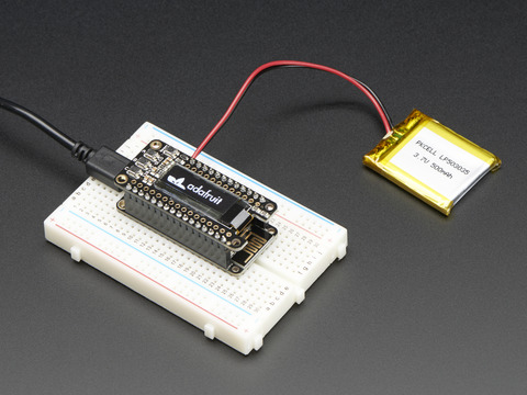
A Feather board without ambition is a Feather board without FeatherWings! This is the FeatherWing OLED: it adds a 128x32 monochrome OLED plus 3 user buttons to any Feather main board. Using ...
wraith current
@trail swallowif you are using a different font or custom font then sometimes the origin of the letter changes.

 trail swallow
Hm, I’m not intending to use a custom font. It happened with the Arduino code demo text too - https://learn.adafruit.com/adafruit-oled-featherwing/usage#run-example-code-2290050-10

And all my code does it set the font size to 1 like the demo does. IIRC it also happens with other font sizes but I’ve spent less time with that.
 mystic gate
hi people, i'm new in electronic, and for now I been making electronic to automate my room, since I got incapacitated, I wanted to have automatic lights, and I been doing tests using development boards, but now I'm trying to make a smaller ones because my house is made of cement and I don't have much space to make a normal circuit, i'm find this squematic on the internet, and it works, but for some reason my led lights remain powered (like those chinese ones), but only glows a little bit, but I don't think that is going to be good at night, it's going to be bad for my sleep, so someone can help me? here is the squematic, one more thing, i had to flip A1 and A2 from the triac so I could fit everything in a small space, could that be the problem?


 north stream
I suspect the dim LED lighting is due to capacitive leakage
mystic gate
yeah, but where it could be the problem? or the most common place to that to happend?
north stream
I'm guessing you have a long wire between your controller and the LED
mystic gate
the bulb terminal?