#help-with-arduino
1 messages · Page 96 of 1
 wispy crater
 limber mauve
anyone around who really knows samd51 DMA?
 thorn spear
limber mauve
anyone around who really knows samd51 DMA?
thorn spear
limber mauve
anyone around who really knows samd51 DMA?
I could direct you somewhere where there are devs that have used the SAMD series and I believe they may be able to help you
limber mauve
I'm digging my way through the adafruit zero DMA source. I understand basically what's going on, but just have a few questions. Where do you have in mind?
thorn spear
limber mauve
I'm digging my way through the adafruit zero DMA source. I understand basically ...
I'll direct you to them, sending a DM
limber mauve
Thanks!
thorn spear
I've asked the guys there on the topic and the one guy who knows about it isn't very friendly or nice, might be a good idea to scrap that idea, I'll keep looking for anyone who can help you
Mind telling me which SAMD51 MCU you're using?
limber mauve
What I'm looking to implement (and currently sketching) is a ping pong DMA'ed buffer receiving off an SPI sercom. I understand the whole
Setting up descriptors and all, but I've had trouble with Arduino dropping interrupts (probably due to USB?)
So I don't want to be dependent on an ISR.
thorn spear
Have you checked the MCU datasheet?
limber mauve
I've been digging in that.
I'm only really starting to dig into the guts of Arduino, even though I've had a pretty good read through the pertinent parts of the MCU data sheet.
I've gotten SPI to work, and I've been doing this with an ISR, but I would love to have it be DMA and keep the processor out of the actual receive.
My goal is to have a single start command that tells the DMA to pull data off the SPI, and then automatically rotate between two buffers (which seems it would be best as two descriptors)
The data sheet seems to suggest that I can do a circular buffer by setting cross-coupled descriptors, but it also implies that I would have to light the DMA transfer back off every time I filled a buffer
I would like to have this just automatically done, and the main loop handle processing of the data after the buffer is full or I've issued some sort of flush command.
I'd like to just set an interrupt flag when DMA switches between buffers, and not actually have to involve the CPU in actually switching.
Essentially, an infinite block transfer
Or initiating a new block transfer as soon as the old one is done without CPU intervention
There's not a ton of data, but it is extremely critical to get all of it, and it pops in every 30 us or so.
Hence the interrupt loss issue, which is normally not a problem.
And then I can use the CPU main loop to check if I flipped a buffer, and then read out that buffer.
Also, I'll readily entertain the idea that I'm just doing it wrong :-)
 north stream
I suspect you'll be stuck involving the CPU
limber mauve
I've also tried downgrading USB interrupts, but what I think is happening is it enters the USB interrupt and locks out nesting, so I lose the RXC interrupt.
I'm also looking at trying tinyUSB instead of the Arduino standard
north stream
There are a few ways to deal with that. One is a "belt and suspenders" approach where the loop checks the buffer full flag as well as an ISR, so it'll get to a missed interrupt, just less fast. If your buffers are big enough (and your event loop efficient enough), that should be fine.
I'd also suggest finding out why the interrupts are being lost
limber mauve
Yeah, I'm extremely curious to where that's happening. I would assume that the likelihood of losing an interrupt would be similar for SPI-RXC and DMA-done, but you'd have orders of magnitude fewer DMA-dones.
The thing is, as I understand tinyUSB from some brief digging, it seems like you can run it even without USB interrupts? I'm using USB as CDC, and timeliness is not a concern wrt USB.
north stream
I doubt USB is your problem, and I'd worry that tinyUSB will eat into your CPU bandwidth.
north stream
Yes, but I still don't think it's your problem
limber mauve
Informationally, I'm getting packets right at the 1 ms rate. It does still feel weird that it would be USB.
north stream
I hate to say it, because it's frustrating and difficult to debug, but it smells to me like a race condition.
limber mauve
But who would be racing who? Also, I'm dropping ~ 1-in-10000 RXC's.
north stream
I'm thinking the ISR needs to re-enable interrupts each pass through, and you have (effectively) two sources of interrupts with your two buffers.
limber mauve
And it has been frustrating and difficult, to be sure
Actually, lack of clarity on my part. I'm losing the occasional interrupt just with having RXC fire an ISR and read the data, no DMA.
And I'm looking to go to a DMA version to avoid that issue.
And also to give some flexibility in the future for faster data flows
I'm only firing one interrupt/ISR
Except for USB
north stream
DMA will dilute the problem (as you described) but it may not cure it. It does have lots of advantages, but I would (reluctantly, but I'd do it) fix the RXC interrupt problem first, as it's going to be less rare and therefore quicker to nail down.
limber mauve
Which is why my nose is taking me that way
I've started digging into the Arduino core code on the hunt for interrupts being fired, but I'm a circuit designer by trade and this is getting bloody. :-)
I kind of know what I'm doing, but I don't claim to be more than an educated dilettante.
north stream
I've been there. I think you're going in the right direction looking at interrupt priority, and testing with just reads, but I'd suggest going further: catching the RXC interrupts and skipping the read, and seeing if it loses any.
I have no EE degree, but many years of experience debugging bizarre problems.
limber mauve
I've been doing something very similar... Just dumping it into a circular buffer on receive. With SERCOM, you do have to read the data register or manually clear the interrupt.
north stream
So I to am a dilettante, but not an educated one (in the traditional sense, anyway)
limber mauve
Is there such a thing as an experienced dilettante?
There are plenty of educated idiots.
north stream
If there is, I'd like to apply for the position! 😃
I'd try that: skip the read and just manually clear the interrupt and see what happens. More data points = more chances for a clue.
limber mauve
Good point.
Anyway, it is 11:30 on the East Coast, and I need to be a good engineer tomorrow. I appreciate the advice, and the chat!
(also, the handle: 'what do you do for a living?' 'I make electrons go round and round.')
north stream
My current job is supporting IBM's "Watson" artificial intelligence products. My last job was freelancing building custom hardware. I'm on the east coast too and should also be getting some sleep.
If it's not cloudy I may be getting up early to hopefully see the eclipse
 wintry wadi
I just finished my embedded system's class and I was wondering if you guys had any good material to learn microcontrollers? I understand the basics of i2c, spi, and what not. Any thing you guys would recommend? Preferably one with a lot of hands on examples. Thanks!
north stream
The "Learn Arduino" guides on AdaFruit are handy. The first few may cover stuff you already know, but there are others that get into more details on interrupts, timers, etc. It rather depends on which aspects you're interested in.
wispy crater
this is the code
when i try to fetch it with JS from my website, it shows the following error
dashboard:1 Access to fetch at 'http://192.168.29.231/pumpoff' from origin 'http://smartgardenuserdashboard.herokuapp.com' has been blocked by CORS policy: The request client is not a secure context and the resource is in more-private address space `private`. dashboard:128 GET http://192.168.29.231/pumpoff net::ERR_FAILED (anonymous) @ dashboard:128 dashboard:1 Uncaught (in promise) TypeError: Failed to fetch
what is the problem and what do i need to add
Pastebin
Pastebin.com is the number one paste tool since 2002. Pastebin is a website where you can store text online for a set period of time.
PLS HELP
north stream
That's a CORS (cross-origin resource sharing) security violation. You'd have to do whatever the site requires to meet their security posture.
 livid osprey
wispy crater
https://pastebin.com/jthTfE11
this is the code
when i try to fetch it with JS f...
livid osprey
wispy crater
https://pastebin.com/jthTfE11
this is the code
when i try to fetch it with JS f...
Building off of what @north stream mentioned, I noticed your errors are using http URLs, and anything mentioning "secure" probably prefers https. Perhaps look into implementing WifiClientSecure?
 terse smelt
Is there a GoPro wifi remote library for Arduino that supports adjusting the EV? (Exposure value) I found this one but I’m not sure if and how it works with adjusting EV https://github.com/aster94/GoProControl

GitHub
Arduino library to interface with GoPro cameras. Contribute to aster94/GoProControl development by creating an account on GitHub.
 crisp folio
terse smelt
Is there a GoPro wifi remote library for Arduino that supports adjusting the EV?...
crisp folio
terse smelt
Is there a GoPro wifi remote library for Arduino that supports adjusting the EV?...
Looks like it's documented here so shouldn't be too hard to add https://github.com/KonradIT/goprowifihack/blob/master/HERO4/WifiCommands.md

GitHub
Unofficial GoPro WiFi API Documentation - HTTP GET requests for commands, status, livestreaming and media query. - KonradIT/goprowifihack
limber mauve
Stupid question: is there an in-depth explanation somewhere of how Arduino USB uses interrupts? It'd be a pretty advanced topic, and Google doesn't really show much. Not terribly afraid of UTSL, but if somebody's already done it, why not?
 pine bramble
@limber mauve You can visit start.atmel.com
Put together a working board support package for your MCU and try it out yourself.
Then inspect the code used to do it.
That would build some knowledge - not Arduino specific knowledge, though.
 elder hare
// This wont turn off when brightness is 0
_Leds.data()[i] = ColorFromPalette(_ledsettings._palette_current, _ledsettings._palette_picker, Brightness, _ledsettings._palette_blend);

// But this will
_Leds.data()[i] = CHSV(96, 255, _ledsettings._pattern_brightness);
why? 😐
north stream
Is brightness an int or a float? Is FASTLED_SCALE8_FIXED set?
Also Brightness != _ledsettings._pattern_brightness
elder hare
@north stream it's an int 🙂 FASTLED_SCALE8_FIXED is not set (did not know about that one) but never mind when i think about it! why would i need to turn them off in the first place 😅 if you have it on it is for displaying colors not to have them off 😅
but i have another question tho
is this just a "mind trick" or what? im confused!
from pixel(0) to end of strip is "forward"
and from end of strip to pixel(0) is "backward"
all of my other patterns behave this way but this TheaterChase pattern moves opposite
void LEDPattern::TheaterChase()
{
    fadeToBlackBy(_Leds.data(), _NumLeds, 255);

    for (int i = _pattern_position % 3; i < _NumLeds; i += 3)
    {
        _Leds.data()[i] = PaletteMode(i);
    }
}
if i set the number "3" here forward becomes backward and vice versa! but if i set the number 5 it becomes correct
north stream
Which 3? The modulo or the increment?
elder hare
both i guess
i've not tried to set only the one
but i have a guess that it is the modulo
north stream
I'm guessing it has to do with yet another modulo: the index modulo vs the length of the strip. If you add 1 LED to the strip, it may reverse or freeze. If you add 2 LEDs, it would change again (that is, if I'm even barking up the right tree here)
elder hare
oh lol ok uhm... so i just went to adafruit site and looked at how they did their Theater Chase pattern and it just worked
changed it to this
    for (int i = 0; i < _NumLeds; i++)
    {
        if ( ( i + _pattern_position ) % 3 == 0 )
        {
            _Leds.data()[i] = PaletteMode(i);
        }
    }
So I have a fairly complex system that uses adafruit's ft6206 library for its touch interface, and one of the other controller boards has its own i2c comms as well, which I'm having trouble getting data from at the moment. How often does the ft6206 get polled, and can I reduce that by configuring a touch interrupt?
limber mauve
pine bramble
<@!728095654932381699> You can visit `start.atmel.com`
Looks useful for understanding the microcontroller side, though.
pine bramble
@limber mauve I used it a lot the first summer I visited start.atmel.com.
Helped me to contextualize what is going on. ;)
DotStar for ATSAMD21G18A (no idea of what the state of this code is in, been a while):
Init is here, including what I'd labeled USB_0:
https://github.com/wa1tnr/atst_aa_rev03a/blob/master/driver_init.c#L119
PA24/DM & PA25/DP there.
This might be the interface to read in keystrokes (a different program):
https://github.com/wa1tnr/ainsu-CamelForth-d51-usb/blob/master/boards/trellis_m4_usb/src/cf/atsamdx1/atsamdx1_getkey_usb.inc#L5
In atmel start not Arduino (at all):
unsigned int getKey(void) {     // hardware-independent wrapper
    while (strlen(usbd_cdc_in_buffer) == 0) {
        cdcdf_acm_read((uint8_t *) usbd_cdc_in_buffer,
                       sizeof(usbd_cdc_in_buffer));
    }
    uint8_t ch_read = (uint32_t) usbd_cdc_in_buffer[0];
    usbd_cdc_in_buffer[0] = '\0';
    usbd_cdc_in_buffer[1] = '\0';
    return ch_read;
}
atmel start USB stuff uses callbacks which I don't really understand at all; still I was able to fake it fairly well (terrible buffering though).
I tried to borrow from how CircuitPython does it but didn't get too far.
(at the time, their USB stuff seemed to be based in atmel start paradigms)
(They are now TinyUSB oriented, I think - whole other ball game)
Really didn't figure out too much about how Arduino IDE handles USB connections.
limber mauve
I'm going to experiment with start.atmel--I do like the idea of having some programmatic help with the register setups.
That all being said, I'm also thinking about experimenting with MPLABX.
 unique moss
hi, so im learning python right now and when im done and after i do a few projects i want to get into hardware programming using circuit python, but i need to learn how the boards and the ports work first, can anyone recommend any courses to help me learn the hardware aspect of the arduino boards or just any microcontroller board in general
pine bramble
@unique moss People ask that question a lot.
It's probably worth the conversation to explore what is and isn't of interest to you.
The simplest microcontroller can blink an LED.
That realizes in the physical world what was once just a typewriter-based conversation with a 'computer'.
Blinking an LED produces light, which any person can see - and they don't need 'language' to do it.
So that's hardware.
Coding is more like, I type something in, and the computer types something back. Language skills are used for that.
I would get whatever 'arduino' or compatible board strikes your interest, and a 'parts pal' (or similar) kit of electronics parts.
Very little of that parts box will be used, initially.
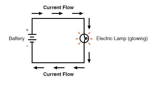
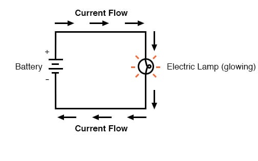
Introductory electronics starts with the flashlight idea (a bulb and a battery and a switch) and builds up knowledge from there.
A test meter to read in Ohms, Volts and Milliamperes is essential for self-study.
pine bramble
An assortment of resistors above 500 Ohms, up to 100,000 ohms and a few LED's and a couple of AA batteries in a holder, a pushbutton switch, some header pins to press into a breadboard (for easy to hookup test points) and a spool of hookup wire, wire strippers, and a breadboard.
I'm sure they got kits with most of that (except for a meter) aren't very expensive.
You only need the spool of wire and wire strippers if you don't buy pre-cut breadboard jumper wires in various short lengths (also as a kit).
A flashlight with a series resistor to limit current flowing through the bulb is most of it - that's a complete 'circuit' and is the basis of all others, in introductory electronics.
unique moss
pine bramble
A flashlight with a series resistor to limit current flowing through the bulb is...
alrighty
thanks alot man
i appreciate your help
pine bramble
When you get through 'Ohms Law' you're in good shape in this textbook:
https://www.allaboutcircuits.com/textbook/
 errant geode
Hello, is there any library to use rfid reader with attiny? I am asking because it probably uses spi, but attiny doesn't work with standard spi library.
crisp folio
Would depend a lot on the specific reader
 median salmon
I'm sure there is a bit banging SPI library somewhere.
 leaden ruin
Which attiny?
median salmon
A bit of google showed me that there is an SPI implementation for the ATtiny using the USI... https://github.com/tessel/avr-usi-spi/blob/master/spi_via_usi_driver.c

GitHub
A USI Library implementing the SPI protocol specifically for AVR chips (tested on Attiny44/84) - tessel/avr-usi-spi
 pallid sage
pine bramble
When you get through 'Ohms Law' you're in good shape in this textbook:
*<https:/...
pallid sage
pine bramble
When you get through 'Ohms Law' you're in good shape in this textbook:
*<https:/...
I have to say that while Ohm's law is great, Kirchhoff's laws are something I wish I was exposed to, like 20 years earlier than I actually was
https://en.wikipedia.org/wiki/Kirchhoff's_circuit_laws
elder hare
hmm looking into hooking up my ESP32 to the Twitch API via WebSocket so that i can listen to the twitch chat of my stream for certain commands beginning with ! but what im struggeling to find out is can my ESP32 (when connected to the twitch API) check if the person/client_id that sent that command has enough channel points and then subtract the amount? 🤔
livid osprey
elder hare
hmm looking into hooking up my ESP32 to the `Twitch API` via WebSocket so that i...
If I remember correctly, you can't directly manage Twitch's channel points through their API, but you can use the API to listen in for custom rewards redemptions. The main drawback to this method is the lack of parameter definitions for custom point quantity redemptions.
That's why most bots still have their own point system despite Twitch creating their own point integration.
This may have changed, as my knowledge probably dates back a couple of years, though...
elder hare
@livid osprey hmmm well that sucks
pine bramble
pallid sage
I have to say that while Ohm's law is great, Kirchhoff's laws are something I wi...
No doubt - they do cover Kirchoff as well as Thévenin (at least to name them and spend ten minutes on each of them) in a semester course in high school (hopefully ;)
 feral pivot
Does anyone knows how to use a library in another library
I made a library but I want to use a display library in it
north stream
I think just #include the header file, and make either a static instance or member instance if need be.
 sudden surge
I am trying to use analog inputs on an Arduino Nano, and I am having some confusing issues. I have the Arduino connected to a breadboard, and if I let the value float on its own, it settles around 200-300. If I try to tie the pin to the ground pin using the breadboard, it continues to float around that 200-300 range, and if I try to connect it to 3v3 it goes up to around 600. Only if I connect them directly to the Arduino and skip the breadboard does it work correctly, going to 0 when tied to ground and going to 1023 when connected to 3v3. I have tried multiple different breadboards and connectors, but that did not help. Does anyone know why this behavior would happen?
north stream
Sounds like a funky breadboard
 soft dust
Does anyone know a good tutorial to control servos with the adafruit servo shield and arduino uno?
north stream
There's a learn page that covers the basics: https://learn.adafruit.com/adafruit-16-channel-pwm-slash-servo-shield
 soft dust
Thanks for the link. However, it is not clear to me how to use this command to convert degrees to pulse lengths with SERVOMIN and SERVOMAX.
 north stream
The map() function is just a numeric range converter: it converts a range of 0 to 180 to a range of SERVOMIN to SERVOMAX.
elder hare
has anyone used any of these and what would you recommend? 🙂
 elder hare
im trying out the ESP_WifiManager_lite
it is booting up and displaying all sorts of info but i cant connect to it via the IP or host name displayed in the serial monitor :S
from the github it is stated
While in AP mode, connect to it using its SSID (ESP_ABCDEF) / Password ("MyESP_ABCDEF"), then open a browser to the Portal AP IP, default 192.168.4.1
this is what i get in the serial monitor when it boots
Starting ESP_WiFi using LittleFS on Espressif ESP32 Dev Module
ESP_WiFiManager_Lite v1.5.0
ESP_MultiResetDetector v1.1.1
LittleFS Flag read = 0xFFFE0001
multiResetDetectorFlag = 0xFFFE0001
lowerBytes = 0x0001, upperBytes = 0x0001
No multiResetDetected, number of times = 1
LittleFS Flag read = 0xFFFE0001
Saving config file...
Saving config file OK
[WML] WiFi networks found:
[WML] 1: Altibox625721, -66dB
[WML] 3: Altibox276123, -81dB
[WML] 4: ASUS_2.4G, -81dB
[WML] 5: Turbo, -85dB
[WML] 6: Omni_7DAFD8, -88dB
[WML]
stConf:SSID=ESP_7BE6E2E0,PW=MyESP_7BE6E2E0
[WML] IP=192.168.4.1,ch=9
F
Your stored Credentials :
Blynk Server1 = account.duckdns.org
Token1 = token1
Blynk Server2 = account.ddns.net
Token2 = token2
Port = 8080
MQTT Server = mqtt.duckdns.org
Stop multiResetDetecting
Saving config file...
Saving config file OK
 wraith current
@elder harelooks like its using the multi reset detector method. reset multiple times in a row and it should boot up into config AP mode.
 viral drum
Hey team, I'm trying to make a simple game on an ESP8266 feather using the OLED Featherwing for display and input. I'm also using Adafruit's GFX library to draw bitmaps. It's getting to the point to where my code is quite large, so I'd like to separate out some of the various functions to dedicated header files in Arduino IDE. For example, my game has multiple various "backgrounds," each of which is drawn to the display object via its own function. The issue I'm running into, however, is that if I move one of these draw functions to a separate header file, it can no longer write to the display object since it's out of scope. I'm fairly new to programming, so I'm not certain how best to approach this. Can anyone offer some advice/recommendations?
north stream
There are a few approaches, you can use inheritance or shared variables. I'll normally make a project-wide header file and declare the display/GFX object in it, then include that file in any module that needs access to it.
Naturally the module that instantiates the object will include the header file too.
 rough torrent
I think you can pass in the OLED object to the function as well, but you will still have to #include the headers files anyways.
But I'm not sure how to do that :/
viral drum
@north stream Right now I'm creating the display object in setup() - are you saying I could create a header file and create it there instead? And that would make it a global object that all header files could access?
north stream
No, keep the place where you create/instantiate it where it is, but make sure it's not local to a function (or declared static) and then in the header file have an additional extern declaration for it.
You're not moving it, just giving more modules access to it.
viral drum
That worked! Very cool, thanks so much 👍 😁
terse smelt
Does anyone have example code or a tutorial for using an ESP32 as a BLE client to connect to a device with a matching UUID and MAC address? Even better if i can send a command to the device. So far the examples i've used just scan all nearby devices and output their information to serial instead of finding a matching device and connecting.
 elder garnet
I'm trying to write a rust library for interfacing with the Adafruit AirLift, which is an esp32-wroom-32f with the WiFiNINA firmware. I can't find any documentation for how to talk to it over SPI, and if possible I would like to avoid reverse engineering the wifinina arduino library.
elder hare
im using this -> https://github.com/khoih-prog/ESP_WiFiManager_Lite and love it! but im having some difficulty trying to get my LED to
- blink slowly when trying to
connect to WiFi - blink fast when in
configuration_mode
i've tried to controll the LED in my header file myWifi.h with delay() but this seems to crash/hault the configuration_mode (i see in the serial monitor that the "multiresetdetection" script spams the serial monitor when i use delay() to blink the LED :S
i've also tried using millis() but with no luck :/

GitHub
Light-Weight MultiWiFi/Credentials Manager for ESP32 (including ESP32-S2 and ESP32-C3) and ESP8266 boards boards. Powerful-yet-simple-to-use feature to enable adding dynamic custom parameters. para...
pallid sage
if delay() kills it, a busyloop looking at the time may also fail?
elder hare
@pallid sage this never triggers :S
        ESP_WiFiManager->begin( "testboard" );

        while ( WiFi.status() != WL_CONNECTED )
        {
            Serial.println("------------------------------------------- WIFI CONNECTING!");
            delay( 500 );
            digitalWrite( WIFI_LED, HIGH );
            delay ( 500 );
            digitalWrite( WIFI_LED, LOW );
        }
Do you see the serial println at all...?
elder hare
@livid osprey no :/
all i get is this
Starting ESP_WiFi using LittleFS on Espressif ESP32 Dev Module
ESP_WiFiManager_Lite v1.5.0
ESP_MultiResetDetector v1.1.1
[WML] Hdr=ESP_WM_LITE,SSID=,PW=
[WML] SSID1=,PW1=
[WML] BName=NewBoard1234
[WML] Hdr=ESP_WM_LITE,SSID=,PW=
[WML] SSID1=,PW1=
[WML] BName=NewBoard1234
LittleFS Flag read = 0xFFFE0001
multiResetDetectorFlag = 0xFFFE0001
lowerBytes = 0x0001, upperBytes = 0x0001
No multiResetDetected, number of times = 1
LittleFS Flag read = 0xFFFE0001
Saving config file...
Saving config file OK
[WML] Hdr=ESP_WM_LITE,SSID=,PW=
[WML] SSID1=,PW1=
[WML] BName=NewBoard1234
[WML] Hdr=ESP_WM_LITE,SSID=,PW=
[WML] SSID1=,PW1=
[WML] BName=NewBoard1234
[WML] bg: Ignore invalid WiFi PWD : index=1, PWD=
[E][WiFiMulti.cpp:187] run(): [WIFI] Connecting Failed (6).
[WML] WiFi connected after time: 1
[WML] SSID=Altibox625721,RSSI=-69
[WML] Channel=2,IP=192.168.10.141
[WS-Server] Websocket Version: 2.3.6
[WS-Server] Server Started.
Stop multiResetDetecting
Saving config file...
Saving config file OK
H
H = connected to wifi
livid osprey
Maybe try adding serial.println(WiFi.status) before the while loop to observe the status prior to the while loop?
elder hare
@livid osprey trying now!
@livid osprey did this
        ESP_WiFiManager->begin( tempBoardName.c_str() );

        Serial.println(" ");
        Serial.printf("Wifi Status : %d \n", WiFi.status());
        Serial.println(" ");

        while ( WiFi.status() != WL_CONNECTED )
        {
            Serial.println("------------------------------------------- WIFI CONNECTING!");
            delay( 500 );
            digitalWrite( WIFI_LED, HIGH );
            delay ( 500 );
            digitalWrite( WIFI_LED, LOW );
        }
output is this
Starting ESP_WiFi using LittleFS on Espressif ESP32 Dev Module
ESP_WiFiManager_Lite v1.5.0
ESP_MultiResetDetector v1.1.1
[WML] Hdr=ESP_WM_LITE,SSID=,PW=
[WML] SSID1=,PW1=
[WML] BName=NewBoard1234
[WML] Hdr=ESP_WM_LITE,SSID=,PW=
[WML] SSID1=,PW1=
[WML] BName=NewBoard1234
LittleFS Flag read = 0xFFFE0001
multiResetDetectorFlag = 0xFFFE0001
lowerBytes = 0x0001, upperBytes = 0x0001
No multiResetDetected, number of times = 1
LittleFS Flag read = 0xFFFE0001
Saving config file...
Saving config file OK
[WML] Hdr=ESP_WM_LITE,SSID=,PW=
[WML] SSID1=,PW1=
[WML] BName=NewBoard1234
[WML] Hdr=ESP_WM_LITE,SSID=,PW=
[WML] SSID1=,PW1=
[WML] BName=NewBoard1234
[WML] bg: Ignore invalid WiFi PWD : index=1, PWD=
[WML] WiFi connected after time: 1
[WML] SSID=Altibox625721,RSSI=-65
[WML] Channel=2,IP=192.168.10.141

Wifi Status : 3

[WS-Server] Websocket Version: 2.3.6
[WS-Server] Server Started.
Stop multiResetDetecting
Saving config file...
Saving config file OK
HHH
Yeah 3 means wl_connected
Your wifi is already connected by the time you reach your awaiting-connection while loop
ESP_wifimanager->begin() is either connecting to your network extremely quickly, or it holds the thread and only releases it after a successful connection.
livid osprey
elder hare
output is this
```
Starting ESP_WiFi using LittleFS on Espressif ESP32 Dev Modul...
I'm not experienced enough to tell you how to get the lights to blink while waiting for connection if you're already connected LOL
elder hare
does this not have an "on board LED" like a normal ESP32? 🤔
Order today, ships today. ESP32-DEVKITC-32UE – ESP32-WROOM-32UE - Transceiver; 802.11 b/g/n (Wi-Fi, WiFi, WLAN), Bluetooth® Smart Ready 4.x Dual Mode Evaluation Board from Espressif Systems. Pricing and Availability on millions of electronic components from Digi-Key Electronics.
 odd fjord
@elder hare Looking at the Schematic https://dl.espressif.com/dl/schematics/esp32_devkitc_v4-sch.pdf the only LED appears to be the 5V power indicator.
elder hare
hmm well that "kinda" sucks 😛 i have a LED on my pcb tho but again would be nice to have the onboard backup but...
odd fjord
What do you mean by "normal" ESP32. There are many ESP32 boards.
elder hare
i know 😛 but i've been using the "DOIT ESP32 DEVKIT V1" and it has a blue LED onboard for "blink sketch" and stuff 😛
but 1 week ago i switched to ESP32-DEVKITC-32UE
wraith current
@elder haremaybe try looking into running a blinking thread on the second core ? I've never done it but I know esp32 has more than one core.
elder hare
anyone who can help me getting some LED magic on this lib -> https://github.com/khoih-prog/ESP_WiFiManager_Lite ? it has LED but only ON or OFF states... what i want is
**LED Off ** (nothing is going on / not connected to Wifi)
LED Slow Blinking (Trying to connect to wifi)
LED Fast Blinking (In configuration_mode)
LED On (connected to wifi)
i tried to using delay/millis and while loops in my myWifi.h header file but this seems to break the lib :S
GitHub
Light-Weight MultiWiFi/Credentials Manager for ESP32 (including ESP32-S2 and ESP32-C3) and ESP8266 boards boards. Powerful-yet-simple-to-use feature to enable adding dynamic custom parameters. para...
 raw flame
Hello, lets say I wanna transfer a lot of data and really often to a microcontroller (ESP32, ESP32-S2, STM32 bluepill, etc.), what would be the best way to communicate from the Host (PC) to the MCU ?
Serial ?
Usb CDC ?
Something else ?
 cedar mountain
raw flame
Hello, lets say I wanna transfer a lot of data and really often to a microcontro...
cedar mountain
raw flame
Hello, lets say I wanna transfer a lot of data and really often to a microcontro...
Generally serial would be the typical go-to default until you know you need something more complex. It should be good up to a few megabits/sec of transfer, so it depends a little on what "a lot of data" means. USB or Ethernet would be the main higher-speed but more complex alternatives, but they're not supported on every MCU.
raw flame
cedar mountain
Generally serial would be the typical go-to default until you know you need some...
Is there alot of commercial products that use Serial communication ?
in term of data it would be 3200bits few times per second
cedar mountain
Commercial products would probably favor USB since it's easier from the user perspective even if more complex on the board side.
raw flame
Okay, I need to find docs/tutorials for Usb communication in Arduino then
most things i found were for usbhost and usb hid
cedar mountain
Note that commercial products generally wouldn't use Arduino, though.
raw flame
u mean software wise (ESP-IDF, etc) or hardware ?
cedar mountain
Both.
raw flame
what type of hardware then ?
cedar mountain
Depends on the product, but for microcontrollers it would be a custom board, and typically pretty cost-optimized.
I guess my main point is that if you're making a commercial product, there are a lot of considerations for the design. And if you're not making a commercial product, then copying what they do for a hobbyist project is not necessarily the right move, since they're following different rules.
raw flame
Its for hobby but wanna do like a real product, if you understand
cedar mountain
You certainly can, just bear in mind that it'll be more complicated that way.
raw flame
thanks for your answers
 next vine
Hi, I built adafruit's sous vide Arduino, which uses adafruit's awesome RGB lcd shield, but I found it impossible to tune the PID parameters... I had to give up. Then I found this other code which doesn't use PID for temperature regulation, but it uses an 8 digit led display and I don't have one of those. Could someone make the code compatible with adafruit's lcd shield? The LED display would take months to arrive, I can't get it locally. Here's the code https://github.com/egiust/SousVideAdaptativeArduino would appreciate help a lot

GitHub
Adaptative regulation sous-vide cooker algorithm (for arduino) - egiust/SousVideAdaptativeArduino
Don't really know if what I'm asking is very complicated or time consuming to do, I started learning python recently but this is a bit too much for me
north stream
Basically, you'd have to narrow down where the code sends data to the display, remove the display specific bits, and replace them with code to write to the LCD.
next vine
I wish I could do that but unfortunately my coding knowledge is very limited, maybe if someone over here could do that for me I could maybe send a free adafruit's RGB lcd shield PCB in exchange
livid osprey
next vine
I wish I could do that but unfortunately my coding knowledge is very limited, ma...
If you have someone refactor the code to support the LCD, why wouldn't you just keep the LCD haha
In my opinion, these DIY projects are meant to be a labor of love. If you really just wanted something working without taking the time to understand how it works, I would recommend spending the money on a consumer sous-vide instead. The amount of money it would cost to pay someone to reengineer the custom code may or may not be a lot depending on the individual, but for a price fair enough for someone to take the time to do it for you, you could probably afford a new sous-vide...
If you have questions regarding how to do it or where to start, feel free to ask. This discussion forum is here to help you fill in the gaps in your knowledge and support you in your DIY journey. Whether it's a question regarding libraries, hardware, or PID tuning, if someone knows the answer or at least something relevant that might help, they'll offer it.
next vine
livid osprey
If you have someone refactor the code to support the LCD, why wouldn't you just ...
I have several pcb's , wasn't saying to send my own soldered pcb haha
thanks anyways I understand now
I try to understand how it works but I enjoy gathering the components and soldering so I can't help but build stuff myself and then struggle with the code haha I'm learning to prevent this
livid osprey
I'm wondering what you mean by being unable to tune the pod, actually. If you have the sous video built, code loaded, and pot filled with water, the auto tuning should get you pretty close?
 brave meadow
I have a Metro Express and I had circuit python on it. However I wanted to go back to Arduino but I can't seem to find the bootloader for Arduino, or maybe I am confused on what I am doing wrong because I can't seem to get things to upload ( I do not just have charing cable as the METROBOOT is available to upload a new UF2 file. The read light is fading in and out at all time no matter if I power cycle or not.
Not sure what to do at this point.
The board is showing up as Com12, I have the IDE setup with the SAMD board management and Arduino M0 selected
I got my bootloader from here: https://learn.adafruit.com/adafruit-metro-m0-express-designed-for-circuitpython/uf2-bootloader-details

Adafruit Learning System
CircuitPython, Arduino IDE or even MakeCode with this Metro M0
And upload it to the bootload storage device and the device restarted when uploaded.
However it is still flashing/fading red in and out
brave meadow
I was able to upload the CircuitPython bootloader and that worked just fine. However I still can't seem to get Arduino to work
next vine
livid osprey
I'm wondering what you mean by being unable to tune the pod, actually. If you ha...
It should, but my rice cooker can't mantain a stable temperature because it loses heat from everywhere, I can't properly seal it and thus I can't find a stable temperature and do the autotuning
brave meadow
wrong board selected... ugh
limber mauve
Is there a port of the SDFat lib that uses DMA on the samd51?
Does the Adafruit port support DMA?
Nevermind. Apparently it does :-)
 median mica
I’m trying to use a servo to mechanically flip a light switch with a d1 mini and Alexa. I’m using a micro servo and with an uno I’m able to flip the switch, but I’d like to use just a d1 mini(esp8266). I’ve tried using external power(5v) for the servo but it doesn’t seem to have enough power to switch the switch. Any suggestions?
 proud meadow
Hello :)..
Can I somehow get rid of the Python-part of the bootloader on my Feather M0 Express and only have an Arduino-bootloader? I don't use the Python part and would like to reduce the startup-time and get rid of the annoying USB-drive that always reconnects when uploading a sketch what throws an error-message on MacOS every time..
north stream
I wonder if there's an Optiboot port for the M0.
elder hare
would this be possible on an ESP32? -> https://www.youtube.com/watch?v=7yY9odZnoJI&ab_channel=QuantitativeBytesQuantitativeBytes

Creating turtle graphics in C++ with the SDL library. Turtle graphics have been around for a long time, since the days that the programming language 'Logo' was taught in schools. The technique can be used to create some rather interesting graphics and also forms the basis of a range of fractal curves that I want to go on to explore in future epi...
cedar mountain
I'm not going to watch a 36-minute video to find out all the possible details, but the short answer is probably yes. The ESP32 is a pretty powerful microcontroller, and Logo used to run on an Apple ][ at a fraction of the capabilities.
wraith current
@median mica what voltage was the servo getting while on the arduino?
 ionic pewter
how do I properly read analog input? my feather m0 spits out this

actually there's also straight text in there, what's the baud rate for the feather m0? I have mine set to 9600
ionic pewter
my sketch
 north stream
That does look like a speed mismatch, which is odd if you have the serial monitor set to 9600 as well
ionic pewter
do you have a really simple "Hello world" i can use to sanity check? this is my specific board: https://learn.adafruit.com/adafruit-feather-m0-radio-with-lora-radio-module/

Adafruit Learning System
Send your message really really far and wide
the blinking led sketch on the docs works just fine i should add
#if defined(ARDUINO_SAMD_ZERO) && defined(SERIAL_PORT_USBVIRTUAL)
  // Required for Serial on Zero based boards
  #define Serial SERIAL_PORT_USBVIRTUAL
#endif

// the setup function runs once when you press reset or power the board
void setup() {
  // initialize digital pin 13 as an output.
  Serial.begin(9600);
}

// the loop function runs over and over again forever
void loop() {
  int red = analogRead(A0);
  Serial.print("Red: " + red);
  delay(1000);
}```
update to my codeI tested without reading the analog, it works and I can read "Red: " in the console, but as soon as I try to throw in the analog value in there it spits out garbage
specifically ????
north stream
Try ```arduino
Serial.print("Red: ");
Serial.println(red);
It works, thank you
median mica
@wraith current I had the servo attached to the 5v pin, ground and pin 9. Based on the basic servo example.
@elder hare they have turtle in Circuit Python, and Circuit Python runs on an ESP32. https://learn.adafruit.com/circuitpython-turtle-graphics?view=all

Adafruit Learning System
No shell scripts here... program turtle graphics in CircuitPython!
 crisp bridge
Hello. I am working with ProTrinketKeyboard lib and have a trouble. KEYCODE_LEFT_SHIFT does not take effect at all in
TrinketKeyboard.pressKey(KEYCODE_MOD_LEFT_CONTROL, KEYCODE_LEFT_SHIFT, KEYCODE_TAB)
It just does Ctrl+Tab. Any idea?
north stream
When you say "does not take effect at all", do you mean within the library, over the wire, or the result on the system that receives it?
crisp bridge
With and without KEYCODE_LEFT_SHIFT does the same.
As a result on the system, both does Ctrl + Tab.
cedar mountain
ionic pewter
I tested without reading the analog, it works and I can read "Red: " in the cons...
Just to explain what was going on there, the "+" operator wasn't doing what you expected in your print statement. Instead of concatenating "Red:" with the string form of the integer red, it was actually taking the pointer address of the constant string "Red:", adding the integer value of red to it, and outputting whatever bytes were at that memory location. Yay for C-style strings...
ionic pewter
cedar mountain
Just to explain what was going on there, the "+" operator wasn't doing what you ...
thanks for the clarification, im personally used to Java and C#
 dusky jay
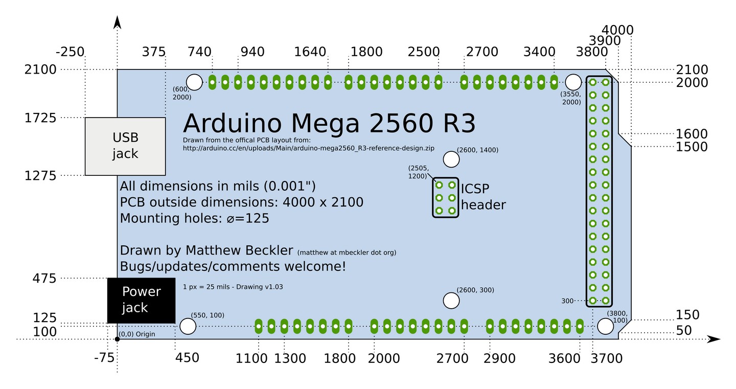
https://cdn-shop.adafruit.com/datasheets/arduino_hole_dimensions.pdf
Not sure if im missing something, but what is the horizontal distance from the top right hole to the bottom right hole on the MEGA?
cedar mountain
dusky jay
https://cdn-shop.adafruit.com/datasheets/arduino_hole_dimensions.pdf
Not sure if...
I agree it looks ambiguous. I don't see anything that specifies the horizontal position of the bottom right hole in this diagram.
dusky jay
Thats somewhat of a relief, lol. I'll prob just print it out since its 1:1 and measure it myself
cedar mountain
Another reference suggests the bottom-right hole is 0.2" from the right edge, or 0.25" from the top right hole.

 novel halo
Hi, I have just got a blackpill and I try to use a lcd st7789 display with adafruit_gfx (which is working properly with my arduino nano). But the blackpill is not able to use the display with the same code. May I know that adafruit_gfx is not compatible with stm32duino that people need to modify the library to make it work on stm32duino? Thanks a lot!
 surreal pawn
@novel halo that library is probably trying to use the faster SPI mode that the samd boards have. You'll might have to poke around inside the library to see where it's going wrong
novel halo
surreal pawn
<@!420208546425077760> that library is probably trying to use the faster SPI mod...
I see, thanks for reply. I just found a st7789 stm32duino repo, which seems to be modified from adafruit gfx, I will try it first thanks!
elder hare
https://github.com/mrfaptastic/ESP32-HUB75-MatrixPanel-I2S-DMA/tree/master/examples/AnimatedGIFPanel
is this only via SD-card or what? it is using SPIFFS...

GitHub
An Adafruit GFX Compatible Library for the ESP32 to drive 64x32px or 64x64px HUB75 LED matrix modules using the ESP32 DMA Engine for faster refresh rates. Supports panel chaining. - mrfaptastic/ESP...
 pseudo abyss


hi i tried burning a bootloader onto my new atmega328p
the device signature says 0x000000
and it says yIKES! and it doesn't work
is my chip dead
 exotic pilot
Hi, anyone got a ESP32 (esp32-uno) connected to MQTT with a weather shield (DEV-13956)?
north stream
It could be a dead chip, or an incorrect connection. That crystal oscillator connection looks a little dodgy, you want those wires to be very short.
One thing you can try is using an external oscillator.
pseudo abyss
hm, gotcha
leaden ruin
That arduinoISP sketch was always a bit of a disappointment.
surreal pawn
I'm using feather m0 and I'd like to go into deep sleep until a pin gets over a threshold voltage. How should I go about doing that?
limber mauve
Are you thinking a precise threshold, or merely a digital input change?
surreal pawn
ASF has two samples that would do what I need. One uses the ADC and the other uses the threshold compare
surreal pawn
ugh, microchip studio shouldn't be failing to work just because I have python 3.8 installed
limber mauve
facepalm
 indigo elm
I'm not sure where to ask this but what are the wiring and pin defines for connecting the eInk Breakout Friend and a ESP32 Huzzah Feather?
surreal pawn
indigo elm
I'm not sure where to ask this but what are the wiring and pin defines for conne...
https://learn.adafruit.com/adafruit-feather-huzzah-esp8266/pinouts
https://learn.adafruit.com/adafruit-eink-display-breakouts/pinouts
Good luck

Adafruit Learning System
WiFi with built-in battery charging for IoT on-the-go!

Adafruit Learning System
Easy E-Paper With Built In Memory
wraith current
@indigo elmthe pins to connect are different for the esp8266 and esp32 so make sure you figure that out.
elder hare
Trying to read a file on the SD-Card (a gif image) and then using animationGIF lib to display it but it crashes what am i doing wrong?
Code : https://hastebin.com/tuqasadama.cpp
Crash: https://hastebin.com/ibecusiroy.apache
 pallid grail
@leaden walrus Does Arduino expect a newline at the end of a file like Python does, or does Arduino not care?
 leaden walrus
for code or serial prints?
pallid grail
Code. As in a whole sketch.
pallid grail
With Python, Pylint will complain if there is not a blank line at the end of a Python program. In this Arduino case, the last thing in this Arduino file is a function, so the last character is }.
Is that all I need then?
No blank line?
leaden walrus
not sure for ci/linting. doubt the compiler cares. but linters are....linty. let me look at some recent stuff.
pallid grail
Wait no.
I haven't sent this Arduino code through a linter yet.
I'm asking preemptively.
Oh I misread what you said. You're verifying.
Ignore me, heh.
Compiler definitely doesn't care, because there's no blank line in this and it works.
leaden walrus
np. actually i bet if you just run clang it'll take care of whatever.
pallid grail
I've never done that
leaden walrus
it does what black does for cp
pallid grail
Ah ok
leaden walrus
pallid grail
Fair enough. Thanks.
leaden walrus
after you install, the key thing is the -i parameter
leaden walrus
without it, it just checks but doesn't actually do anything. -i makes it go ahead and edit in place, which is more like how black behaves
pallid grail
Ah ok
leaden walrus
i don't think it's very chatty. command runs. nothing reported. but does actually change.
you could do something like make a commit, then run clang, then see what the git diff shows. or run clang without the -i to see what it wants to gripe about.
pallid grail
I looked at the file and it doesn't look any different, so I'm guessing I was ok. But 🤷♀️
Ah fair enough
leaden walrus
yah. i just run it blindly as like a last step. some of it's formatting can be a bit 🤷 . but just have to accept it to pass.
pallid grail
Thanks @leaden walrus! Appreciate the help as always.
leaden walrus
np
indigo elm
surreal pawn
https://learn.adafruit.com/adafruit-feather-huzzah-esp8266/pinouts
https://lear...
I followed that originally but it was a bit unclear WRT the esp32. I have another wrinkle that I'll post in a follow on question...
indigo elm
wraith current
<@!627710819412607016>the pins to connect are different for the esp8266 and esp3...
I figured as much, I think the write up on the AF website is older and there is very little about how to connect it to the ESP32. I had to resort to the picture, and guess.
Still not sure if this is the place to ask this but there is another BIG wrinkle to what I'm trying to do (WRT connecting an ESP32 to the eInk Breakout Friend). I'm hacking a solution. I'm trying to drive a Pimoroni eInk What (4.2" RBW) by connecting the EPD ribbon cable to the eInk BreakoutFriend. I'm not sure what the manufacturer is for the EPD so, it's basically a crap shoot. Thoughts? Should I move this question?
pine bramble
HELLO i am trying to hook up a LSM6DS33 gyro sensor and i cant seem to figure out pinouts. Im using it to home a rotating arm. thank you!
 vivid rock
Have you checked this guide?
https://learn.adafruit.com/lsm6ds33-6-dof-imu=accelerometer-gyro

Adafruit Learning System
Take a measure of your orientation on six axes
 civic umbra
I know its not legal to use, but just for pentests, has anyone made a wifi deauther?
pine bramble
so im running multiple steppers off of multiple adafruit stepper motor controlboards. and i want to use this sensor. But i cant seem to get it to work with the sheilds
can anyone help me?
vivid rock
@pine bramble what exactly are you trying to do? how do you want to use this sensor?
and - if you forget about the shields, can you get data such as x-, y-, z- gyro reading from this sensor?
pine bramble
yes i can get that data
i using it for a rotating arm
its to wrap candies. It as a claw that has another stepper motor and a it will have a large slip ring so it can spin freely
i need to use the sensor for homing
i need it pretty level
Here is a video
vivid rock
the obvious and most straightforward algorithm would be:
- compute the angle between the sensor and horizontal , say by using a.x^2+a.y^2 to measure deviation from horizontal -- if board is horizontal, then a.x, a.y are zero or very close to it. Note that I am using accelerometer, not gyro values
- rotate the stepper until the board is horizontal
pine bramble
yes i know hahahahaha
vivid rock
Slightly more advanced version would slow done the rotation once the board is close to horizontal; this would make it easier
pine bramble
well i was just gonna do the math
but that might be better cause then i dont have to think about the math
vivid rock
you do not need math
pine bramble
you know what i mean
i was going to home it then have it go a certain amount of steps
vivid rock
well, let us first make sure we can home it, then talk about next steps
pine bramble
the arms arent just going to go back and forth
they gonna twist and then realease the clamp
but i cant home it without knowing how to use the sensor with the motor control boards
vivid rock
you use an arduino or similar board to control everything, right?
vivid rock
so then here is the algorithm:
- connect the motor control boards and sensor to arduino
- start rotating the stepper
- repeatedly get the sensor reading
- stop rotating then a.x^2+a.y^2 is close enough to zero
sorry, busy day today, will have to go in 2 minutes
vivid rock
what do you mean?
pine bramble
about what part
vivid rock
adding back
pine bramble
on discord?
vivid rock
sorry, I do not follow you. Sure we are on discord
vivid rock
oh. Sorry, I do not use this feature. You can reach me here when I am available without being my friend
got to run now, will see you later
pseudo abyss
north stream
It could be a dead chip, or an incorrect connection. That crystal oscillator co...
wait so what does device signature 0x000000 meann

okay it doesn't look like the chip is dead
because i put VCC and GND in, and i used the other vcc and gnd pins from the chip to power the led
and that seems to be working
so it seems like i just screwed up with the connections
 hybrid plank
that doesn't really mean anything. those might be just directly connected inside the chip
hybrid plank
may be dead, may have been connected wrong, may have the incorrect fuse settings
north stream
Normally 0x000000 (all zeros) or 0xffffff (all ones) mean a connection problem that keeps the data from being read properly.
pseudo abyss
oh gotcha
elder hare
i realy realy REALY need some help here! i've asked befor but have been unsuccessful at fixing this! my problem is; im trying to load a gif image from the SD-Card but the ESP32 Wemos crashes everytime it hits this line FSGifFile = SD.open(fname);
code;
https://hastebin.com/robohokino.cpp
Serial Monitor crash;
https://hastebin.com/otugatuxuz.yaml
cedar mountain
My next step would be to decouple the SD stuff from the GIF library by just doing a manual open and read of a small text file on the card or something. I'm suspecting there's some problem with the SPI setup of the SD Card library, which isn't getting exposed until it actually tries to read something.
elder hare
@cedar mountain i've done that and it worked super!
SD Card Type: SDHC
SD Card Size: 30436MB
Listing directory: /
  DIR : /System Volume Information
  FILE: /test.txt  SIZE: 1048576
  FILE: /foo.txt  SIZE: 13
  FILE: /34.GIF  SIZE: 2297211
  FILE: /Mandala2.gif  SIZE: 881482
Creating Dir: /mydir
Dir created
Listing directory: /
  DIR : /System Volume Information
  FILE: /test.txt  SIZE: 1048576
  FILE: /foo.txt  SIZE: 13
  DIR : /mydir
  FILE: /34.GIF  SIZE: 2297211
  FILE: /Mandala2.gif  SIZE: 881482
Removing Dir: /mydir
Dir removed
Listing directory: /
  DIR : /System Volume Information
Listing directory: /System Volume Information
  FILE: /System Volume Information/WPSettings.dat  SIZE: 12
  FILE: /System Volume Information/IndexerVolumeGuid  SIZE: 76
  FILE: /test.txt  SIZE: 1048576
  FILE: /foo.txt  SIZE: 13
  FILE: /34.GIF  SIZE: 2297211
  FILE: /Mandala2.gif  SIZE: 881482
Writing file: /hello.txt
File written
Appending to file: /hello.txt
Message appended
Reading file: /hello.txt
Read from file: Hello World!
Deleting file: /foo.txt
File deleted
Renaming file /hello.txt to /foo.txt
File renamed
Reading file: /foo.txt
Read from file: Hello World!
1048576 bytes read for 1153 ms
1048576 bytes written for 2482 ms
Total space: 30419MB
Used space: 4MB
Oh, this might be it. Your SPIClass object is a local variable of the setup() function, so it might not persist when the GIF library actually tries to access the card later in loop(). I'd change that to a global and see if it makes a difference.
elder hare
testing now! 👍
 scarlet cipher
hello i have a question, can somebody help me?
cedar mountain
scarlet cipher
hello i have a question, can somebody help me?
The rule of thumb is just to ask your question, rather than waiting for a volunteer who doesn't even know whether they will have the answer.
scarlet cipher
ah cheers
i'm having a problem with the feather m0 adalogger, when i connect it to my computer i get an error balloon from windows saying, "USB device not recognized // The last USB device you connected to this computer malfunctioned, and Windows does not recognize it." I've tried many things including switching out the cables, USB ports, double-clicking the reset button during upload, switching a different board of the same model and turning on/off my computer. I've read on the forums that suggest updating the driver, but i can't do that since i operate the arduino IDE straight out of the extracted zip file it downloaded in (i've done this for years and i've never had an issue with it)
has anyone had an issue like this?
leaden walrus
what version of windows?
scarlet cipher
windows 10
scarlet cipher
yes, i've tried the one i'm working on and blink. unfortunately neither have worked
leaden walrus
blink is good for testing
you've gone through the arduino ide setup? to install SAMD board support?
scarlet cipher
i have done that also
hybrid plank
what do you mean by "operate the arduino IDE straight out of the extracted zip file it downloaded in" -- are you double-clicking the zip file and running the IDE out of there? or did you extract it first?
scarlet cipher
i extracted it first
leaden walrus
that should be fine also. it's pretty self contained.
what board are selecting in Tools->Board?
scarlet cipher
"Adafruit Feather M0"
scarlet cipher
COM8 is showing up, which is new
it used to return nothing
but even that does not help the upload
leaden walrus
windows can be weird with the COM port number
tends to bounce between two numbers between uploads
what error message do you get when you try to upload blink?
scarlet cipher
update: COM8 just disappeared. i was able to get it to show up by double-clicking the reset button during the blink upload. Regardless of whether i have a COM port to select, the error is the following: "Couldn't find a Board on the selected port. Check that you have the correct port selected. If it is correct, try pressing the board's reset button after initiating the upload."
leaden walrus
scarlet cipher
are you referring to the 3rd item down in the list?
leaden walrus
yep. the "ack i did something" one.
scarlet cipher
right okay, i have tried that one. that's what i mean when i say "double-click during upload"
leaden walrus
did it successfully upload when you tried that?
scarlet cipher
it did not
i still get the same, "Couldn't find a Board on the selected port. Check that you have the correct port selected. If it is correct, try pressing the board's reset button after initiating the upload."
leaden walrus
you got the error message above?
scarlet cipher
correct
leaden walrus
hmmm. what arduino ide version are you using?
scarlet cipher
1.8.15
leaden walrus
should be fine. what about the versions for the SAMD BSPs? both Arduino and Adafruit?
scarlet cipher
i have both, i'm not sure what the version number is but i updated them last friday
arduino samd v1.8.10, adafruit v1.6.7
 scarlet cipher
doing that now crossing all my appendages
still has an issue finding a port, for reference when i try to select it manually the option is unselectable
leaden walrus
seems like something might be interfering
scarlet cipher
aw man
elder hare
have i done something wrong here? (trying to run the websocket on Core 0) i noticed when trying to connect to the ESP32 with all the libs running that it just hanged around for 5-7min befor connecting) so i thought it would be a good idea to have the socket on Core 0..
#include <Arduino.h>

#include "mythWifi.h"
#include "GIFDisplay.h"
#include "mythSocket.h"

TaskHandle_t Task1;

void Task1code( void * parameter)
{
  for(;;)
  {
    mythSocket::loop();
  }
}

void setup()
{
  Serial.begin(115200);

  mythSocket::begin();

xTaskCreatePinnedToCore(
      Task1code, /* Function to implement the task */
      "Task1", /* Name of the task */
      10000,  /* Stack size in words */
      NULL,  /* Task input parameter */
      0,  /* Priority of the task */
      &Task1,  /* Task handle. */
      0); /* Core where the task should run */
}

void loop()
{

}
but it keeps crashing :S
hmm apparently i NEED to have a vTaskDelay(10); inside the Task....
scarlet cipher
is there a way to fry a feather m0 from uploading?
north stream
The worst thing I can think of would require it to be reloaded with SWD or somesuch.
 rich coral
is it possible to make sharp memory display auto scroll with println ?
 young dust
I've created a web server on my arduino which receives post requests and displays a message on the screen, but punctuation seems to be converted to some sort of %__ format
For instance "Hi there!" becomes message_content=Hi+there%21
Is anyone familiar with that format?
north stream
Yes, that's "URL encoding". Spaces are converted to + and several other special characters are converted to % and their hex representation
livid osprey
They become spaces now? Wow, long ago were the days of the dreaded %20s....
north stream
%20 is also valid for spaces, but + is offered as a more compact option.
 heavy star
 waxen hawk
Hey guys, im a beginnerish to arduino. I was wondering if i am using the arduino ide, could it also compile .cpp and .h files in the same folder?
 lone ferry
Yep, just add them in the same folder @waxen hawk
waxen hawk
lone ferry
Yep, just add them in the same folder <@!238851726789181440>
Thanks for replying. I haven't experimented but can .ino files (acting as main) include helper c files and utilize their functions as wells?
lone ferry
Yes. In a number of my own projects I have a main .ino file and the rest are .h and .cpp files.
waxen hawk
Nice! glad to have that flexibility.
lone ferry
The .ino file is treated a bit special by the compiler though. So if you need to use Arduino stuff in your .cpp files you need to #include <Arduino.h> at the top.
 grim basalt
Hello guys could anyone tell me what is trending and the latest mini project ideas based on Arduino
 coarse breach
Hi, I'm trying to work on FreeRTOS using Arduino, I've run into a few issues, can someone help me out?
I wanted to know the significance of an infinite loop inside a task, can that while(1) be replaced with say, an external hardware signal check statement so that the task executes only when I trigger it with a signal?
leaden walrus
in general, when working with an RTOS, you create a bunch of "tasks", each of which is an infinite loop. it's the job of the RTOS to manage switching between each task. there are also various interprocess communication (IPC) mechanisms which are provided for doing additional coordination between tasks. so you'd want to retain the while(1) loop and find some other way to communicate the hardware signal to the task.
coarse breach
Alright thank you! Appreciated
Just researched about vTaskSuspend() and vTaskResume(), looks like they might do the trick
cedar mountain
A typical RTOS task will be waiting on some event most of the time, like a signal from an interrupt that would come through one of the OS notification mechanisms. I'd tend to shy away from explicitly suspending and resuming tasks.
coarse breach
From the resources i've seen online, most of the tasks have a delay statement at the end, which lets the processor move to the other tasks. Will I be better off using a hardware interrupt if I want my code to be solely controlled by an external signal?
cedar mountain
Generally, yes, since you'll get notified right away when the event happens, and don't need to have your task periodically polling for the status.
A standard pattern, for instance, is to have a semaphore that your task blocks on, which the ISR toggles when the hardware interrupt occurs.
coarse breach
Oh wow, that sounds elegant, basically try making use of a binary sephamore that is toggled by a hardware interrupt in my task
Will give it a shot, thanks
elder hare
can some explain to my why this crashes?
    uint8_t        _xyz[256] = { 0, 255, 0, 0 }; // { 0, 255, 0, 0, 255, 0, 255, 0 }
    CRGBPalette256 _myPal = _xyz;
Rebooting...
CORRUPT HEAP: multi_heap.c:432 detected at 0x3ffdfff8
abort() was called at PC 0x4008ce67 on core 0

ELF file SHA256: 0000000000000000

Backtrace: 0x40088b20:0x3ffdf900 0x40088d9d:0x3ffdf920 0x4008ce67:0x3ffdf940 0x4008d42c:0x3ffdf960 0x40081e5d:0x3ffdf980 0x40081e8e:0x3ffdf9a0 0x40086bb9:0x3ffdf9c0 0x4000beaf:0x3ffdf9e0 0x401676ff:0x3ffdfa00 0x400d7a6a:0x3ffdfa20 0x400d7ca5:0x3ffe3b90 0x4015c6c3:0x3ffe3bb0 0x4008495d:0x3ffe3bd0 0x40084b8c:0x3ffe3c20 0x40079247:0x3ffe3c40 0x400792ad:0x3ffe3c70 0x400792b8:0x3ffe3ca0 0x40079465:0x3ffe3cc0 0x400806da:0x3ffe3df0 0x40007c15:0x3ffe3eb0 0x4000073d:0x3ffe3f20
CORRUPT HEAP means memory gets overwritten that shouldn't be
north stream
There's a possibly-useful writeup about such issues here: https://docs.espressif.com/projects/esp-idf/en/latest/esp32/api-reference/system/heap_debug.html#finding-heap-corruption
 river osprey
I booted up Arduino IDE (windows 10) today and it forgot my boards, so I went to board manager, and reinstalled, but now when i go to compile, I get "recipe.preproc.macros pattern is missing" I'm trying to compile/upload for an Itsy Bitsy m4 express, but I think this is an arduino IDE issue - i tried re-installing all the drivers and boards, but it didn't work. Any thoughts?
leaden walrus
there's one directory you need to manually delete for a true clean reinstall
C:\Users(username)\AppData\Local\Arduino15
 mystic gate
Hi guys, maybe someone knows what happends here? in this video you can see my ESP8266 with a Hlk-pm03 power supply and a solid state relay, i connect 2 10k resistor from 3.3v from ps, to 0 and 2 pin (using 0 as relay, and 2 as push button), a cable from 3.3v to EN pin in the ESP8266, when using it outside with a extension cord (from the wall to the power supply with a cord), works fine, then at the time of putting it the wall cables, works fine for a couple of minutes, but then it starts to do this thing in the video, blue led starts to blink very fast and the SSR too, (i think because the number 2 pin is used by the blue led), and it just does not work, do you know what could be the problem? here the video and the code.
demo
 exotic rain
Hello
I have a project that has to be done tonight. I really need help controlling a stepper motor. I have an image of it attached. I have zero arduino experience. All of the tutorials use a kind of stepper that I dont have and dont have time to order. I need to be able to control it with the picture of the attached potentiometer.
mystic gate
do you have an stepper driver?
exotic rain
yes
I have all of the components from this kit:https://www.amazon.com/gp/product/B01EWNUUUA/ref=ppx_yo_dt_b_asin_title_o03_s00?ie=UTF8&psc=1
Amazon.com: ELEGOO Mega 2560 R3 Project Starter Kit Compatible with Arduino IDE MEGA 2560 - Including 16 Tutorials CD: Computers & Accessories
mystic gate

Learn how to use stepper motors with the Arduino.
Full Article with Code at https://dbot.ws/stepper
More articles and tutorials: https://dronebotworkshop.com
Join the conversation on the forum: https://forum.dronebotworkshop.com
Subscribe to the newsletter and stay in touch: https://dbot.ws/dbnews
Today we will be working with stepper motors, ...
exotic rain
Does it show me how to control it with the 10K potentiometer?
mystic gate
you need a digital potentiometer
and it's supper easy with the digital one
i don't know if you can do it with a 10k tho
mystic gate
here
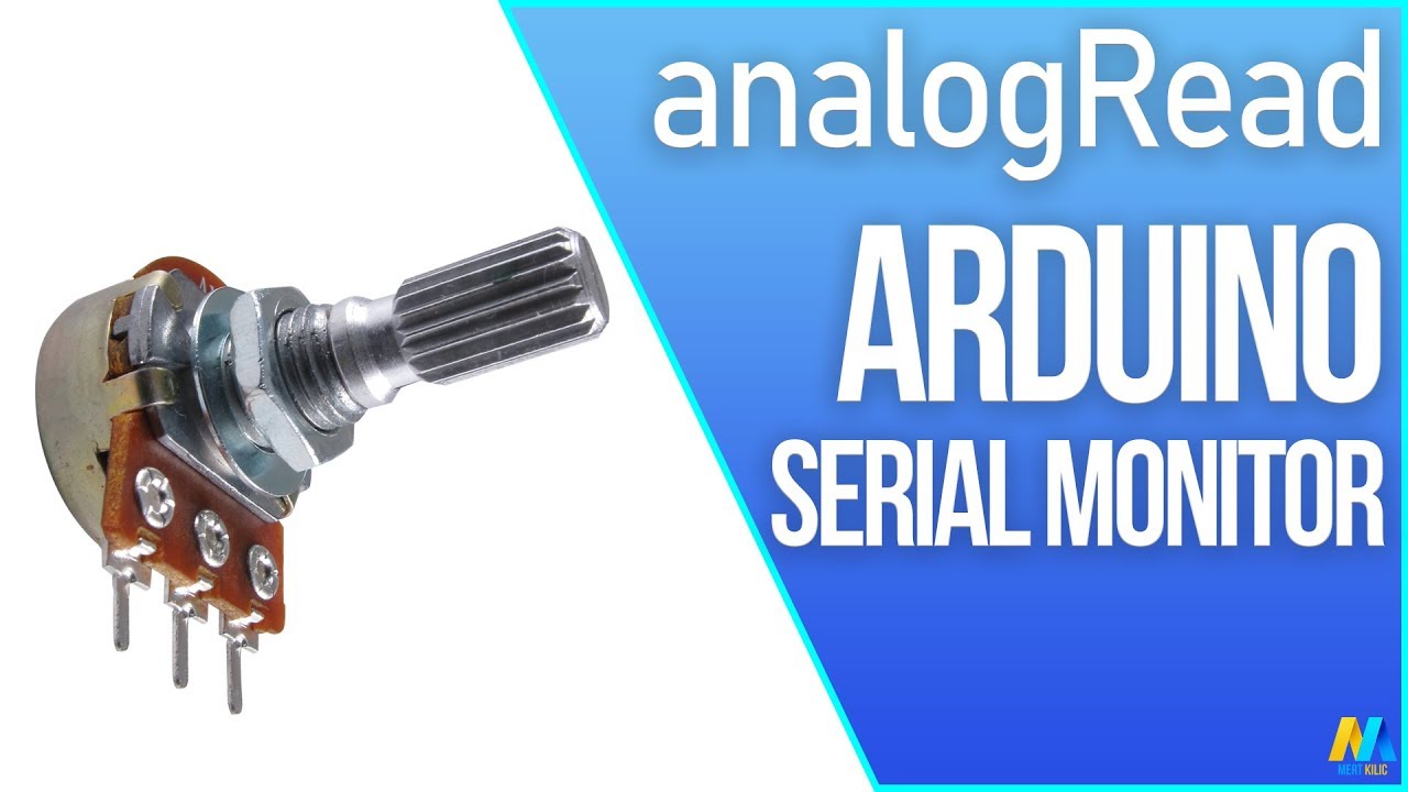
Arduino basic tutorial "analogRead" Serial Monitor with Potentiometer. Reads an analog input on pin A0, prints the result to the serial monitor.
Connections
Attach the center pin of a potentiometer to A0, and the outside pins to +5V and ground
Arduino UNO: https://amzn.to/2LZr6t4
Breadboard : https://amzn.to/3qxL
Jumper Wire: https://amzn.to/...
very easy to read the potentiometer value
int sensorValue = analogRead(AO);
AO is the analog pin from the arduino
A0 i meant
now look at the values the potentiometer gives, and look at the values the stepper needs
then you can normalize the potentiometer values or something, and at the end use the first video to pass the values to the stepper
here is your code, from the first video
// Include the AccelStepper Library
#include <AccelStepper.h>
// Define Constants
// Define step constants
#define FULLSTEP 4
#define HALFSTEP 8
// Define Motor Pins (2 Motors used)
#define motorPin1 8 // Blue - 28BYJ48 pin 1
#define motorPin2 9 // Pink - 28BYJ48 pin 2
#define motorPin3 10 // Yellow - 28BYJ48 pin 3
#define motorPin4 11 // Orange - 28BYJ48 pin 4
#define motorPin5 4 // Blue - 28BYJ48 pin 1
#define motorPin6 5 // Pink - 28BYJ48 pin 2
#define motorPin7 6 // Yellow - 28BYJ48 pin 3
#define motorPin8 7 // Orange - 28BYJ48 pin 4
// Define two motor objects
// The sequence 1-3-2-4 is required for proper sequencing of 28BYJ48
AccelStepper stepper1(HALFSTEP, motorPin1, motorPin3, motorPin2, motorPin4);
AccelStepper stepper2(FULLSTEP, motorPin5, motorPin7, motorPin6, motorPin8);
void setup()
{
// 1 revolution Motor 1 CW
stepper1.setMaxSpeed(1000.0);
stepper1.setAcceleration(50.0);
stepper1.setSpeed(200);
stepper1.moveTo(2048);
// 1 revolution Motor 2 CCW
stepper2.setMaxSpeed(1000.0);
stepper2.setAcceleration(50.0);
stepper2.setSpeed(200);
stepper2.moveTo(-2048);
}
void loop()
{
//Change direction at the limits
if (stepper1.distanceToGo() == 0)
stepper1.moveTo(-stepper1.currentPosition());
if (stepper2.distanceToGo() == 0)
stepper2.moveTo(-stepper2.currentPosition());
stepper1.run();
stepper2.run();
}
just remove the second stepper values and just do like this stepper1.moveTo(potentiometer_values);
@exotic rain I hope it helps you.
now, can someone help me please? I don't know what it happends and it's driving me crazy!
mystic gate
mystic gate
Hi guys, maybe someone knows what happends here? in this video you can see my ES...
this comment please
pseudo abyss
north stream
Normally `0x000000` (all zeros) or `0xffffff` (all ones) mean a connection probl...
okay i have spent 2 hours just inspecting this thing, i can't find any reason for it to not work other than it's dead. i'm attaching 2 images of this from 2 different angles, and i think i fixed the crystal connection


this is the original thing i'm basing it off of, i even printed out the pinout of the chip and it all seems to make sense
north stream
The truth is that "it's dead" is indeed one of the possibilities, and, alas, an increasingly likely one as the others become less probable.
 torpid reef
So honestly, I'd get the crystal right up against the chip and take the ceramic caps straight to the ground rail, no jumpers That's a lot of long jumper wires there that I'd be worried the crystal isn't getting started.
I see you were having trouble getting the thing to read via programmer before, however, so not sure.
terse smelt
Does anyone familiar with ESP32 and BLE know how to pair after connecting to a device? It doesn’t have a PIN or passcode.
leaden ruin

Instructables
How to Use Arduino Mega 2560 As Arduino Isp: When i build my Atmega328p-pu on a circuit board for my moped i needed to bootload it.
Because i have none external programming equipment i needed to use my Arduino Mega 2560 as ArduinoISP ( http://arduino.cc/en/Tutorial/ArduinoISP &n…
Looks like you're not on the hardware SPI pins, @pseudo abyss .
 light shale
pseudo abyss
okay i have spent 2 hours just inspecting this thing, i can't find any reason fo...
light shale
pseudo abyss
okay i have spent 2 hours just inspecting this thing, i can't find any reason fo...
The Mega has the SPI pins on different Digital Pins then the UNO. If you look at @leaden ruin link it shows. It gets confusing because the ISP example code give you the pins for the UNO and some of the online examples assume your using a UNO as well
elder hare
is it true that if there is no client connect to my ESP32 in a while it will lose the DNS/hostname?
livid osprey
mystic gate
Hi guys, maybe someone knows what happends here? in this video you can see my ES...
If you have a voltmeter, check the voltage drop across the resistor to 2? It might be a floating voltage.
mystic gate
livid osprey
If you have a voltmeter, check the voltage drop across the resistor to 2? It mig...
ok let me check
 opaque roost
Anyone know a faster way to update a tft screen instead of using fillScreen();
waxen hawk
Hi, do anybody know how to determine a sensor is analog or signal. I have largely using sensors using digital inputs (temperature, pressure) but I wanted to experiment with programming using analog pins (arduino uno). Is there a way to confirm whether a sensor is purely analog or capable of both digital and analog?
livid osprey
waxen hawk
Hi, do anybody know how to determine a sensor is analog or signal. I have largel...
Google its datasheet, if you have the sensor's part number.
waxen hawk
livid osprey
Google its datasheet, if you have the sensor's part number.
is there a way just be looking at the sensor (i.e. number of pins?)
livid osprey
waxen hawk
is there a way just be looking at the sensor (i.e. number of pins?)
Not one that applies universally to every type of sensor in existence. What are you looking at?
waxen hawk
livid osprey
Not one that applies universally to every type of sensor in existence. What are ...
Just confirming if HC-SR04 Ultrasonic sensor also output analog signals.
waxen hawk
livid osprey
Not one that applies universally to every type of sensor in existence. What are ...
believes this is the only datasheet: https://cdn.sparkfun.com/datasheets/Sensors/Proximity/HCSR04.pdf
livid osprey
As far as I know, hc-sr04 uses the time difference between a trigger pulse output and its reflection to measure distance.
Not sure if there's any such thing as an hc sr04 with an analog output.
waxen hawk
I see. Perhaps i try a different sensor, I've looked this up and it said that it was analog but wanna confirm is LM35 temp sensor and photoresistor do output analog signals?
livid osprey
Lm35 looks to output an analog signal, yes. Photo resistors change their resistance based on the luminosity at its receiving surface, and will return an analog signal with the proper circuitry.
waxen hawk
livid osprey
Lm35 looks to output an analog signal, yes. Photo resistors change their resista...
Great. Thank you. I appreciate having a confirmation.
livid osprey
opaque roost
Anyone know a faster way to update a tft screen instead of using fillScreen();
Not that I know of, assuming you're restricted to the adafruit_gfx library and spi interface.
opaque roost
livid osprey
Not that I know of, assuming you're restricted to the adafruit_gfx library and s...
thanks, i just found its easier to update the shape seperately instead of using fillScreen();
waxen hawk
Hi just asking around cuz StackO resources but have anybody use DHT11 temperature sensors. I've been largely getting nan values and using tillbart's library. (i can confirm the sensor works and connections are tight using a multimeter).
livid osprey
Not sure which library that is. Have you tried other libraries? Adafruit has its own here: https://learn.adafruit.com/dht

 solar plover
waxen hawk
Hi just asking around cuz StackO resources but have anybody use DHT11 temperatur...
solar plover
waxen hawk
Hi just asking around cuz StackO resources but have anybody use DHT11 temperatur...
I used DHT11 couple of days ago and all I needed was Adafruit_Python_DHT library
https://github.com/adafruit/Adafruit_Python_DHT

GitHub
Python library to read the DHT series of humidity and temperature sensors on a Raspberry Pi or Beaglebone Black. - adafruit/Adafruit_Python_DHT
 pure stag
yo Im trying to hook up a 8x8 led matrix to my arduino
online some people use resistors while some not
should I use it or
eg.

 pseudo abyss
i think you should use resistors
just in case
also if you have details on your specific led matrix, find out how much resistance you need
(am i doing well, helpers? are those good tips)
livid osprey
When in doubt, use a resistor. An ideal diode will have zero resistance, but having zero resistance mean you basically have a short circuit with infinite current. While that isn't ever the case in real life, a series resistor is always recommended to protect your arduino from drawing too much current from a single pin.
If the brightness is too low, you can try a smaller resistance value, but I strongly recommend having a series resistance if you don't know it's internal resistance.
pure stag
okay thank you guys
 tired gazelle
Hey yall, Its particle so its not the same thing, but im having an issue where my Particle Argon is not reading Air quality correctly in this script
When I run the script that just checks for air quality alone, theres no problem, but im trying to make a script that combines reading data from a PM2.5 PMS5003 sensor, and a DHT22 for temperature humidity and airquality


this is the script
and this is the output I get

and this is the output I get just running the script with the air quality sensor
 pure stag
Hi
I'm using this code to multiplex a 8x8 led matrix
void pushFrame() {
    for (int row = 0; row < 8; row++) {
        setROW(row+1, HIGH);
        for (int col = 0; col < 8; col++) {
            if (frame_buffer[row][col] == true) {
                Serial.print(col);
                setCOL(col+1, HIGH);
            }
            delayMicroseconds(20);
            setCOL(col+1, LOW);
        }
        setROW(row+1, LOW);
    }
}
where frame_buffer is an 8x8 bool array
but for some reason when I for example turn on light (1,1) the entire row behind it lights up too
like this:

anyone see why?
north stream
I don't know what setROW or setCOL do, but I'd move that delay() outside the col loop
pure stag
it just turns on/off the corresponding row/col indexed from 1 to 8
north stream
Actually have two col loops, one turns on the LEDs, then the delay, then one turns them back off. While that's not really your problem, it's more usual multiplexing practice.
pure stag
void pushFrame() {
    for (int row = 0; row < 8; row++) {
        setROW(row+1, HIGH);
        for (int col = 0; col < 8; col++) {
            if (frame_buffer[row][col] == true) {
                Serial.print(col);
                setCOL(col+1, HIGH);
            }
        }
        delayMicroseconds(20);
        for (int col = 0; col < 8; col++) {
            setCOL(col+1, LOW);
        }
        setROW(row+1, LOW);
    }
}
Like this I suppose u mean
pseudo abyss
#include <util/delay.h>

int main(void){

  DDRB = 0b00000011; // Sets PB0 and PB1 to outputs

  while(1){

    PORTB = 0b00000001; // Turns on only PB0
    _delay_ms(2000); // Delays 2000ms (2s)

    PORTB = 0b00000010; // Turns on only PB1
    _delay_ms(2000); // Delays 2000ms (2s)

     PORTB = 0b00000001; // Turns on only PB0
    _delay_ms(1000); // Delays 1000ms (1s)

    PORTB = 0b00000010; // Turns on only PB1
    _delay_ms(1000); // Delays 1000ms (1s)

     PORTB = 0b00000001; // Turns on only PB0
    _delay_ms(500); // Delays 500ms (0.5s)

    PORTB = 0b00000010; // Turns on only PB1
    _delay_ms(500); // Delays 500ms (0.5s)

  }
  return(0);
}```

```Arduino: 1.8.15 (Windows Store 1.8.49.0) (Windows 10), Board: "ATmega328, Yes (UART0), EEPROM retained, 328P / 328PA, BOD 2.7V, LTO disabled, External 16 MHz"

Warning: Board breadboard:avr:atmega328bb doesn't define a 'build.board' preference. Auto-set to: AVR_ATMEGA328BB

Sketch uses 142 bytes (0%) of program storage space. Maximum is 32256 bytes.

Global variables use 0 bytes (0%) of dynamic memory, leaving 2048 bytes for local variables. Maximum is 2048 bytes.

avrdude: stk500_recv(): programmer is not responding

avrdude: stk500_getsync() attempt 1 of 10: not in sync: resp=0x9d

avrdude: stk500_recv(): programmer is not responding

avrdude: stk500_getsync() attempt 2 of 10: not in sync: resp=0x9d

avrdude: stk500_getsync() attempt 3 of 10: not in sync: resp=0xe0

avrdude: stk500_getsync() attempt 4 of 10: not in sync: resp=0xe0

avrdude: stk500_getsync() attempt 5 of 10: not in sync: resp=0xe0

avrdude: stk500_getsync() attempt 6 of 10: not in sync: resp=0x00

avrdude: stk500_getsync() attempt 7 of 10: not in sync: resp=0xe0

avrdude: stk500_getsync() attempt 8 of 10: not in sync: resp=0xe0

avrdude: stk500_getsync() attempt 9 of 10: not in sync: resp=0xe0

avrdude: stk500_getsync() attempt 10 of 10: not in sync: resp=0x00

Problem uploading to board.
i uploaded the sketch and got this error
i'm using an atmega328p that i MANAGED TO BURN THE BOOTLOADER ON
THANK YOU @north stream @light shale @leaden ruin
but yeah i tried uploading a sketch, it did not work
north stream
Hmm, is your port, board, and programmer set right? Is the cable working?
pseudo abyss
i mean, i'm using the same setup as the bootloader thing
i didn't change anything except for wiring PB0 and PB1 to LEDs
and just to make sure, i burned the bootloader a second time
that works fine
pseudo abyss
north stream
Hmm, is your port, board, and programmer set right? Is the cable working?
the port is fine, the board sHOULD be fine, the programmer miiight not be fine
lone ferry
Is this an official Arduino? If not, you will need to install additional drivers.
leaden ruin
How do I write an Arduino sketch to a FunHouse board that is currently running CircuitPython? It resets and goes back into CP and the Arduino upload times out.
 brittle merlin
Could anyone help me convert this micropython to Arduino, I've tried but I cant figure it out
    R = 6372.8 # For Earth radius in kilometers use 6372.8 km
    dLat = radians(lat2 - lat1)
    dLon = radians(lon2 - lon1)
    lat1 = radians(lat1)
    lat2 = radians(lat2)
    a = sin(dLat/2)**2 + cos(lat1)*cos(lat2)*sin(dLon/2)**2
    c = 2*asin(sqrt(a))
    calcDist = R * c * 1000
    calcDist = '{0:.2f}'.format(calcDist) # to 6 decimal places
return calcDist```Most of the code should be pretty similar, though you'll probably have to #include <math.h> to get the trig functions.
brittle merlin
I got this far:
float distanceBetween(float lat1, float lon1, float lat2, float lon2){
    float R = 6372.8; // For Earth radius in kilometers use 6372.8 km
    float dLat = radians(lat2 - lat1);
    float dLon = radians(lon2 - lon1);
    lat1 = radians(lat1);
    lat2 = radians(lat2);
    float a = sin(dLat/2)**2 + cos(lat1)*cos(lat2)*sin(dLon/2)**2;
    float c = 2*asin(sqrt(a));
    float calcDist = R * c * 1000;
    calcDist = '{0:.2f}'.format(calcDist); // to 6 decimal places
    return calcDist;
}
but it throws up errors for two of the lines and its way over my head, errors:
sketch_jul01a:19: error: invalid type argument of unary '*' (have 'int')
float a = sin(dLat/2)**2 + cos(lat1)*cos(lat2)sin(dLon/2)**2;
sketch_jul01a:19: error: invalid type argument of unary '' (have 'int')
float a = sin(dLat/2)**2 + cos(lat1)*cos(lat2)*sin(dLon/2)**2;
sketch_jul01a:22: error: request for member 'format' in '775054973', which is of non-class type 'int'
calcDist = '{0:.2f}'.format(calcDist); // to 6 decimal places
Apologies if ive converted anything wrong.
leaden ruin
leaden ruin
How do I write an Arduino sketch to a FunHouse board that is currently running C...
I held the BOOT button during Reset. After Reset the board was on a different COM port. I was then able to upload my sketch. Required a manual reboot, then it was on a third COM port. But it is now running! 🎉
cedar mountain
brittle merlin
I got this far:
```
float distanceBetween(float lat1, float lon1, float lat2, fl...
Ah, C++ doesn't have the power operation, so you'll want to use the exp() function instead, or else just convert the square to a multiplication.
And for the format(), there are other ways to do the string formatting, for instanceString distance = String(calcDist, 2);
pseudo abyss
@lone ferry how do i find out which drivers i need?
brittle merlin
brittle merlin
I got this far:
```
float distanceBetween(float lat1, float lon1, float lat2, fl...
Not sure if this is the best way to do it but someone else made this up to do what I wanted
constexpr auto pi = 3.14159265358979323846;

double distanceBetween(double lat1, const double lon1, double lat2, const double lon2)
{
    const double d_lat = (lat2 - lat1) * pi / 180.0;
    const double d_lon = (lon2 - lon1) * pi / 180.0;
    lat1 = lat1 * pi / 180.0;
    lat2 = lat2 * pi / 180.0;

    const double a = pow(sin(d_lat / 2), 2) + pow(sin(d_lon / 2), 2) * cos(lat1) * cos(lat2);
    const double rad = 6372.8;
    const double c = 2 * asin(sqrt(a));
    return 1000 * (rad * c);
}
Thank you to @cedar mountain who tried to help me even though im such a noob and was still confused lol
north stream
C uses a different idiom for exponentiation, but since it's simple squaring, you can just multiply it by itself.
 severe thistle
Hey guys, so I have a couple of ESP32 boards which I am trying to use with the arduino ide
So none of the esp32 boards that I have are detected by the ide. I have installed the drivers for the CP2102 chip but even that doesnt help. The port isn't detected at all and when it is detected it doesnt work, and some error shows up like esptool not installed (which i did install) or board not connected but the red light on the board is always on.
I tried using VSCode and platformio but that seems to have its own set of problems with the libraries
I have tried all the suggestions I could find on the internet. I have restarted my laptop connected the esp to a different port
I am kind of lost here. Would appreciate if someone could help
north stream
Does the port even enumerate?
waxen hawk
Not sure if this is the best place to post my question, but do anybody have any suggestions in how to solder very small pins that are close together?
cedar mountain
You'll want a small-tipped soldering iron, small-diameter solder, and optical magnification of some sort. That last is surprisingly useful, since working under magnification actually improves your hand-eye coordination: the brain gets better feedback about what your fingers are doing.
north stream
And flux. Flux makes everything easier
pine bramble
Dudes
I have an esp32 and a stepper motor and a stepper motor driver (ULN2003A)
Ik that the driver is needed because the esp alone would get fried if it drove the stepper motor since motors do need a lot of current
But i simply dont know how i arrange the connections
Do they only need to share a common ground ?
Is it even possible to connect both to the same power supply ?
I find many different scheme which all show something different


 north stream
Yes, a common zero volt reference is required, otherwise it should work. You can use a shared supply in this case, since the ESP32 has its own regulator which will isolate it from the electrical noise of the stepper.
pine bramble
Ok how do i have to connect it when i want to power the driver from a 12V max 2A power supply, and the ESP32 from a 5V max 200mA power supply
I want to power the ESP32 from my laptop, but the high current that passes through the motor shouldnt pass through my laptop because it cant handle that much
north stream
That makes sense.
So you'd plug the ESP32 into 5V, so it has power. You'd hook the stepper driver to the 12V supply so it too has power, then you'd connect the ESP32 0V reference to the stepper driver 0V reference.
north stream
Yes, almost the same.
pine bramble
It works
But it also works when there is no common ground
Is it possible that the power line acts as a common ground ?
north stream
Possibly: some laptops supplies connect to earth ground. I don't know what you're using as a 12V supply. But as long as the MCU and the stepper driver can agree on what 0V is, you're good.
 quasi crest
Hi guys, I'm currently working on connecting an adafruit QT Py to a flow sensor. The manufacturer provides arduino code to connect the sensor to an arduino uno. What would I need to add to this code to have it connect to the qt py instead? I've been having trouble with this and any help is appreciated, thanks.

GitHub
Arduino Code Snippets for Raw Sensor Communication with Sensirion Liquid Flow Sensors - Sensirion/arduino-liquid-flow-snippets
rough torrent
it looks like it should be wire-i2c device and upload to qt py - what trouble are you having?
quasi crest
When I connect it and upload, it continuously sends the print on line 68 with an error
Although, I'm not entirely sure what it translates to. Is the qt py unable to make a connection to the computer or the sensor itself?
north stream
Seems like an I2C problem, I'd probably run an I2C scan and see what the results are
 fleet edge
Hi, currently running an Arduino mega fitted with a LSM303 IMU and a servo. My code reads compass headings and moves servo in order to follow a given heading ie 0deg , North. Code works perfectly. I've also got it connected to a Raspberry pi and can read the heading ad servo position on a Terminal via serial. ATM to change the desired heading I need to open the IDE ad change the script. How can I do this via serial.
leaden walrus
you want to be able to enter Target at run time?
fleet edge
@leaden walrus That's correct. Its a boat that I'm trying to run semi auto. So ideally SSH into Pi and change Target when required.
leaden walrus
the mega is attached to the pi?
fleet edge
Correct via usb at present.
leaden walrus
one idea would be to ditch the mega and control everything directly from the pi. you'd switch to python in that case.
north stream
I figured the question was "how to accept serial data in the sketch and use it to populate a variable"
leaden walrus
otherwise, you can try sending to the mega over the serial port - i.e. serial monitor
north stream
Something like ```arduino
#define BUFSIZE 32
static char buffer[BUFSIZE];
static char * bp = buffer;
static char * bend = buffer + BUFSIZE;
void loop()
{
int ch;
if (Serial.available()) {
// read serial byte into ch
if (ch == '\n') {
*bp++ = '\0';
Target = atoi(buffer);
bp = buffer;
} else {
if (bp < bend) {
*bp++ = ch;
}
}
}
@north stream would you mind explaining the script I'm rather a noob.
north stream
Yes, that's what the comment is for: I couldn't remember the "get a byte" routine and was just banging that off from memory.
In short, it collects a character at a time until it finds a newline, then it terminates the string and hands the result off to the atoi() routine to convert it into an integer.
cedar mountain
(I think you may have a chance of buffer overflow when doing the null termination case.)
north stream
Yes, I skimmed over a lot of details
This is not finished, ready to run code, just an illustration of how one (of many possible) approaches might work
exotic rain
Hello
I need some help understanding this schematic
I do not know much about arduino yet
north stream
Note: it's easier for people to post a picture instead of something they have to download and then open in a separate app
north stream
The schematic is pretty straightforward, it's a bunch of switches wired to inputs, and some shift registers to control some LEDs
exotic rain
Do you know how to make it in fritzing?
I am using these switches https://www.amazon.com/gp/product/B00004WLK8/ref=ppx_yo_dt_b_asin_title_o01_s00?ie=UTF8&psc=1
Buy Gardner Bender GSW-125 Electrical Toggle Switch, SPST, ON-OFF, 6 A/125V AC, 6 inch Wire Terminal: Toggle Switches - Amazon.com ✓ FREE DELIVERY possible on eligible purchases
north stream
An actual picture like this is easier
 exotic rain
What do you mean?
north stream
I mean that it's easier for people to view actual pictures (which show up directly in Discord) than files like PDF and FZZ that they have to download and then view in a separate application.
exotic rain
Oh ok i am sorry
north stream
No worries, just something for future reference
pine bramble
Dudes ok now i have a 12v max 2.5A power supply which is connected to one device that needs 12v but now i want to add another device to that same power supply but this device needs only 5v
What can i do to regulate the 12v down to 5v only for that one device
A voltage divider doesnt work because the supplied voltage depends on the current consumed by the device
 stable forge

This little buck converter based on the MPM3610 is a marvel, taking up to 21V input and providing a 5V output with up to 1.2A current. It's great for supplying power to popular 5V ...

Your power supply problems just got SOLVED! This little circuit board may look tiny but inside is a high efficiency DC/DC step-down converter which can output up to 3 Amp at 5V without the ...
@pine bramble ^^
pine bramble
Is there no simple circuit that i can build myself
stable forge
you need a regulator IC. and some extra components,
it's a linear regulator, so it will waste power. Needs a few caps
the buck converter is cheap enough and is more efficient
https://www.adafruit.com/product/2236 if you don't need that much current

Need a nice little 5V regulator? We rather like the very-low-dropout L4931 from ST! This little guy will help you get your 5.5-20V battery or wall adapter down to a nice clean 5V with 2% ...
there are thousands of regulators available as parts
@pine bramble if it's not a lot of current, you can use a zener diode also: http://www.calculatoredge.com/electronics/zener.htm
waxen hawk
cedar mountain
You'll want a small-tipped soldering iron, small-diameter solder, and optical ma...
👍
waxen hawk
north stream
And flux. Flux makes everything easier
Thanks, flux definitely help. Also helps deoxidize stuff.
I was able to solder my stepper motor (to impart some wisdom to other soldering beginners, make sure to use a wick cuz i made a lot of mistakes). Do anybody have suggestion of how to make stepper motor produce a frequency? (using it produce a scale i.e. 440 HZ = A4 note) I'm using #include <Adafruit_MotorShield.h> library with the adafruit motor shield.
north stream
You could work backwards from the frequency to figure out what the commanded motor speed should be to step at that frequency, or work around it so you could drive the step input with a PWM output you control.
waxen hawk
north stream
You could work backwards from the frequency to figure out what the commanded mot...
Do you know if there is a formula relating motor speed relate to sound frequency?
north stream
It would something like (steps per revolution * phases per step) / (RPM * 60) or somesuch
er, not sure either.
waxen hawk
Yeap, i think the correlation between sound frequency and speed is still unclear (speed does relate to frequency but not sure how much and adafruit forums don't have concrete answers).
I am investigating a bit for now but for everyone's information (or if you guys are interested): there is a very awesome guide of someone's project: https://github.com/jzkmath/Arduino-MIDI-Stepper-Motor-Instrument. However, I am using the provided motorshield v2.3 to drive instead of the A4988 Stepper Driver so i don't know if i can control PWM from motor shield.
north stream
I suppose you could look at the source code for the library to find the calculation it uses from RPM to pulse rate and just invert that (since pulse rate is what you want)
waxen hawk
Thats a good suggestion! I will try looking at that too.
 wise socket
GitHub
Arduino Code Snippets for Raw Sensor Communication with Sensirion Liquid Flow Sensors - Sensirion/arduino-liquid-flow-snippets
wise socket
wise socket
https://github.com/Sensirion/arduino-liquid-flow-snippets/blob/master/SF06/examp...
I am trying to use this code to connect a sensirion sensor to a qt py and I have double checked the pins and it shows up on an I2C scan
However it does not get past the initial do while loop that checks if the sensor is being found
cedar mountain
It might help if you print out the return code from endTransmission(), since it'll specify when the NACK happened.
wise socket
cedar mountain
It might help if you print out the return code from `endTransmission()`, since i...
I am away from my computer at the moment but I will revisit this with you later if you don't mind
cedar mountain
wise socket
I am away from my computer at the moment but I will revisit this with you later ...
Sure. Just continue to post info and questions to the channel, and if I'm not around, someone else will likely pop in to help... there's a lot of experience with I2C issues here.
surreal pawn
What version of ASF does https://github.com/adafruit/Adafruit_ASFcore use? I'm guessing 3.29 which isn't listed for download on https://www.microchip.com/mplab/avr-support/avr-and-sam-downloads-archive

GitHub
ASF core files for Zero. Contribute to adafruit/Adafruit_ASFcore development by creating an account on GitHub.
I'm essentially trying to combine the ASF AC deep sleep example with an arduino sketch on feather m0 and I'm hoping it's easier to add the parts of ASF I need to the library than to drop arduino and somehow get everything running on ASF, or port sample code away from ASF
also the 3.9.1 download doesn't work
actually, the downloads archive list isn't sorted correctly and 3.29 is there
 alpine girder
Hey im a complete newbie and im trying to figure out what all i need to get neopixels connected to my arduino, when i look at the guides they recommend to use a capacitor, but when i watch videos on the subject almost nobody uses one, what all do i need to buy to get neopixels up and running on my arduino?
 pale drift
hi @alpine girder , I hadn't used caps in-line w/neopixels in the past, but I have had enough problems with them in costumes etc. that I do now. They'll work fine without that extra 1000uf capacitor until they get a power spike of some sort caused by some other short down the line etc.
adafruit's own guide is the best: https://learn.adafruit.com/adafruit-neopixel-uberguide/powering-neopixels

Adafruit Learning System
Everything you always wanted to know about Adafruit NeoPixels but were afraid to ask
 modest python
All -i don't seem to get any power when i plug in an external power supply to the boards jack..is this a thing? i thought it would draw power automatically
modest python
modest python
All -i don't seem to get any power when i plug in an external power supply to th...
Arduino Uno
north stream
Some have a power switch you need to set for them to come on. You can also check the external supply to see if it's the proper voltage/polarity/type.
modest python
north stream
Some have a power switch you need to set for them to come on. You can also chec...
5v power supply - checked it works with another device (guitar effects pedal) and i can't see anything on the arduino uno to switch the power on to it once plugged in-google seems to say it should choose power source automatically
exotic rain
Does anybody have an idea on how to use these switches with an uno?

 woeful drift
Do you need to carry all that current that they're rated for or are you using them more for the look of the switch?
I guess I mean to ask are they for controlling a larger load or simply just for input to the Arduino?
north stream
In general, hook the switch between a GPIO pin and ground, and configure the pin as INPUT_PULLUP. Then when the switch is open, it will read high (due to the pullup), and when the switch is closed, it will read low (due to the switch pulling the pin to ground).
limber mauve
That is a ...lot of switch for an Arduino project.
 crimson radish
How could I specify the i2c pins for a BMP280 using the Adafruit BMP280 library
cedar mountain
crimson radish
How could I specify the i2c pins for a BMP280 using the Adafruit BMP280 library
It looks like you can pass in a TwoWire object in the constructor, if you're using a nonstandard I2C bus.
mystic gate
livid osprey
If you have a voltmeter, check the voltage drop across the resistor to 2? It mig...
sorry for not answering, had a rough week, and how can I fix the issue if is a floating voltage?
livid osprey
mystic gate
sorry for not answering, had a rough week, and how can I fix the issue if is a f...
You can try a smaller resistor, or take it out altogether? I don't remember what the circuit was.
mystic gate
Ok
mystic gate
mystic gate
Hi guys, maybe someone knows what happends here? in this video you can see my ES...
this one
well I don't know if is a floating voltage because the other day I remove the 10k resistor and still did the same.
livid osprey
How did you wire up the button?
crimson radish
cedar mountain
It looks like you can pass in a `TwoWire` object in the constructor, if you're u...
..what exactly would that look like? Sorry, I'm new to coding 😬.
I tried this but it didnt work (probably an ovbious error, but oh well
 cedar mountain
crimson radish
..what exactly would that look like? Sorry, I'm new to coding 😬.
cedar mountain
crimson radish
..what exactly would that look like? Sorry, I'm new to coding 😬.
It would be likeAdafruit_BMP280 bmp(&Wire1);for example if you wanted to use the second I2C bus on a board. Not every pin is allowed to use I2C, so there are specific buses that are set up for it, called Wire, Wire1, etc.
pine bramble
Hello experts
I'm using an Arduino Pro Mini and have leds attached to pins 10 and 11.
I want to use analogWrite to adjust their brightness.
Each led circuit has a low side mosfet controlled by the Arduino with a CCR and the LED in series.
However, when I use the lines:
analogWrite(10,50);
analogWrite(11,50);
.. The leds don't turn on.
It should be noted that these lines are added to an existing program which otherwise works.
- Is it a problem that I want to analogwrite them both?
- Does analogWrite need a library to work?
- Does analogWrite require exclusive accesss to any timers or similar?
north stream
You should be able to write analog values to two pins at once. No separate library is required, analogWrite() is built into the basic Arduino framework. It does, however, use PWM, which in turn depends on timers.
exotic rain
woeful drift
I guess I mean to ask are they for controlling a larger load or simply just for ...
I am mainly using them for looks. what i am doing is using it turn an led from red to blue. Then, repeat that 5 times. On the 6th time, it will turn a servo. Then i will have a seventh switch to reset evrything.
And by reset i mean turn the servo opposite direction and set all lights back to red.
woeful drift
Ah I get it now. I suppose in that case since you're only using them to send a signal to the Arduino then just do what madbodger mentioned earlier:
madbodger — 07/03/2021
In general, hook the switch between a GPIO pin and ground, and configure the pin as INPUT_PULLUP. Then when the switch is open, it will read high (due to the pullup), and when the switch is closed, it will read low (due to the switch pulling the pin to ground).
You can just solder some smaller wire too to the switch's leads since you wouldn't need to carry the full rated current of the switch
I think (but somebody correct me if i'm wrong) that the wire that fits into breadboards and Arduino pins is 22 AWG
cedar mountain
Yep, there's some range, but 22 is perfectly normal for hookup wire.
exotic rain
Ok! Thanks guys!
 rocky schooner
I want to have a screen like this. What do I have to google to get a LC display like this?

I want to use it with the arduino and with the adafruit Feather M0. Pls ping me
 deep steeple
This may be a dumb question but could I wire 2 ir sensors to one port on an arduino or would it better to just code it in for multiple ports?
I have an area that would get better coverage with 2 sensors but not sure best way to handle multiple
cedar mountain
rocky schooner
I want to use it with the arduino and with the adafruit Feather M0. Pls ping me
That would generally be described as a monochrome graphic LCD.
cedar mountain
deep steeple
This may be a dumb question but could I wire 2 ir sensors to one port on an ardu...
What kind of sensor is it? If it's I2C or SPI, they can generally share a bus. If it's more of a direct connection, they usually wouldn't easily do so.
crisp folio
rocky schooner
I want to have a screen like this. What do I have to google to get a LC display ...
If you're looking to design your own EEVblog has this video and a series around LCDs https://www.youtube.com/watch?v=ZYvxgl-9tNM
How to design a custom multiplexed LCD display.
Dave takes you through what is required to design your own custom LCD display and what consideration you need for manufacturing and choosing an LCD display driver.
Part 3 in the LCD Tutorial series.
Forum: http://www.eevblog.com/forum/blog/eevblog-1055-how-to-design-a-custom-lcd/
EEVblog Main We...
deep steeple
cedar mountain
What kind of sensor is it? If it's I2C or SPI, they can generally share a bus. I...
It’s the direct to a data pin I figured that I’d just have to use two data pints so not a huge deal or changes in code at least
I’m planning on using one arduino nano as my slave to get ir signals then use the i2c bus to send data to a second one to control neopixel patterns and brightness since it doesn’t play nice trying to run on the same arduino
deep steeple
ok maybe dumb question but why will this lower my brightness but not raise it?
  case 70:
          if(strip.getBrightness() <= 255){
             strip.setBrightness(strip.getBrightness() + 5);
             strip.show();
          }else
            Serial.println("MAX BRIGHT");
      case 21:
          if(strip.getBrightness() > 0){
            strip.setBrightness(strip.getBrightness() - 5);
            strip.show();
          }
it seems to always run the if brightness < than 255 but doesn't adjust the brightness
dimming is working perfectly as expected
odd fjord
Are you sure case 70 is getting triggered?
deep steeple
yes I added some serial prints to check and it is printing the brightness it just doesn't change
case 70:
          if(strip.getBrightness() <= 255){
             Serial.println(strip.getBrightness());
             int new_bright = strip.getBrightness() + 5;
             strip.setBrightness(new_bright);
             strip.show();
          }else
            Serial.println("MAX BRIGHT");
      case 21:
          if(strip.getBrightness() > 0){
            strip.setBrightness(strip.getBrightness() - 5);
            strip.show();
          }
this was with some extra prints and tweaks
odd fjord
ah -- you need a break at the end of the case -- it is running from case 70 in to case 21 and undoing the increase.
deep steeple
ah ok thank you always those dumb little things I forget
deep steeple
thanks appreciate it. I finally got a second arduino nano so using 2 as a slave/master setup to do some controlling of my neopixels with an IR remote
odd fjord
Sounds like fun! Good luck with it.
deep steeple
thanks I had a hacky version working before with both on one but this is much smoother and running nice so far with just one test strip
pine bramble
I'm having trouble with getting my String to print. I'm using this library: https://github.com/adafruit/Adafruit_LED_Backpack
Heres my code: https://clbin.com/Mez0N
It just cuts off (uploading vid):
 solemn cliff
pine bramble
It just cuts off (uploading vid):
solemn cliff
pine bramble
It just cuts off (uploading vid):
you loop with a int8_t
ueoa will be something like - (747 + 3) * 7, which an int8 would never reach, but if there's an implicit conversion in x >= ueoa, you would expect the scroll to end within 128 pixels, which is 18 characters (with a 7 width), which takes us to the beginning of the first the
or something like that I suspect
pine bramble
solemn cliff
you loop with a `int8_t`
this was it! thank you!
What's the usual reason you would want to use int8_t ?
north stream
Normally smaller variables like that are used to save space or increase speed (the original Arduino AVR is an 8-bit chip, so works well with 8-bit variables)
 mortal ridge
So I am using the Adafruit stepper shield V2. I have a stepper motor connected to it.
So has anyone used the adafruit V2. I have been trying to get my code to work. I have run the example code from the library, and it worked perfect. I built my code off of that, and I am wondering why it isnt working. The program runs and everything in the serial monitor works, but in the places where the motor should run....nothing happens.
Pastebin
Pastebin.com is the number one paste tool since 2002. Pastebin is a website where you can store text online for a set period of time.
compare this to the StepperMotor example code
I have and have no idea why my code doesnt move the motor
north stream
It looks like it blocks waiting for a digit, then parses the digit as a motor RPM, which would be a very slow RPM
pine bramble
Error:
error: too many initializers for 'const char* [1]'
Code:
const char* wifis[][1] = {{"SSID","PASS"},{"SSID","PASS"}};
How do I make this char* 2D array? I've been trying for like 30 min xD
cedar mountain
At the risk of stating the obvious, you've got a 1-element array specified, but the data has dimensions of 2.
pine bramble
cedar mountain
At the risk of stating the obvious, you've got a 1-element array specified, but ...
LMAO that was it! XD Thank you!!!
 tight badge
Hello All,
I am trying to get the aw9523 to work with an rgb led using the stemma off of a qt py with a light sensor also stemma. I have the code below. I had the light sensor working with an RGB led on the py itself but cant get the aw9523 to work.
#include <Arduino.h>
#include <hp_BH1750.h> // include the library
#include <Adafruit_AW9523.h>
hp_BH1750 BH1750; // create the sensor
Adafruit_AW9523 aw;
const int Red = 1;
const int Green = 3;
const int Blue = 2;
uint8_t Red1 = 0; // 0 thru 15
void setup() {
// put your setup code here, to run once:
Serial.begin(9600);
bool avail = BH1750.begin(BH1750_TO_GROUND);// init the sensor with address pin connetcted to ground
// result (bool) wil be be "false" if no sensor found
Serial1.begin(115200);
while (!Serial1) delay(1); // wait for serial port to open
Serial1.println("Adafruit AW9523 GPIO Expander test!");
if (! aw.begin(0x58)) {
Serial1.println("AW9523 not found? Check wiring!");
while (1) delay(10); // halt forever
}
Serial1.println("AW9523 found!");
aw.pinMode (Red1, OUTPUT);
pinMode (Red, OUTPUT);
pinMode (Green, OUTPUT);
pinMode (Blue, OUTPUT);
}
void loop() {
// put your main code here, to run repeatedly:
BH1750.start(); //starts a measurement
float lux=BH1750.getLux(); // waits until a conversion finished
Serial.println(lux);
if (lux > 20) analogWrite (Green, 256);
if (lux > 20) analogWrite (Red, 256);
if (lux > 20) analogWrite (Blue, 256);
if (lux > 20) aw.analogWrite (Red1, 256);
if (lux < 20) {
analogWrite (Red,0);
aw.analogWrite (Red1,0);
}
}
cedar mountain
tight badge
I am trying to get the aw9523 to work with an rgb led using the stemma off of a ...
Can you clarify what it's doing or not doing? Is it not even detected, or is it apparently working but just not lighting up the LED, or...?
tight badge
I get nothing from it
cedar mountain
It looks like the aw.analogWrite() call takes a uint8_t parameter, so the value needs to be 0-255.
cedar mountain
What do you mean by "I get nothing from it"?
tight badge
No reaponce, is there a way to tell if the board is reaponfing?
cedar mountain
It looks like you're using both Serial and Serial1. Perhaps you're only looking at the outpuf of one of them?
tight badge
Yeah i did that thinking it might help
cedar mountain
Address 0x58 would be with both AD pins left at the default.
cedar mountain
I'd advise simplifying the scenario and just trying to get the AW9523 detected at all first.
tight badge
Will do, and i will change the address as well. Thanks
 fluid nebula
Wondering if this FRAM library by @split forge will likley work with other sizes of Fujitsu FRAM chips (like the MB85RC128APNF 128Kb) https://github.com/adafruit/Adafruit_FRAM_I2C

GitHub
Driver for Adafruit's I2C-Based FRAM Breakouts. Contribute to adafruit/Adafruit_FRAM_I2C development by creating an account on GitHub.
north stream
It seems likely, especially with the same vendors, but a data sheet check would be wise.
tight badge
@cedar mountain do you know what the appropriate new address would be with them both jumped?
 exotic arch
Hey guys, is there any good case around for the arduino mega that is sturdy but thin enough to provide access to all pins / HAT Support?
tight badge
I am trying the code below with just the AW9523 attached to the py. #include <Arduino.h>
#include <Adafruit_AW9523.h>
Adafruit_AW9523 aw;
uint8_t Red1 = 10; // 0 thru 15
void setup() {
// put your setup code here, to run once:
Serial.begin(115200);
while (!Serial) delay(1); // wait for serial port to open
Serial.println("Adafruit AW9523 GPIO Expander test!");
if (! aw.begin(0x5B)) {
Serial.println("AW9523 not found? Check wiring!");
while (1) delay(10); // halt forever
}
Serial.println("AW9523 found!");
aw.pinMode(Red1, OUTPUT);
}
void loop() {
// put your main code here, to run repeatedly:
aw.analogWrite (Red1,0);
delay (1000) ;
aw.analogWrite (Red1, 255);
}
Still no response from the LED. The power light is on so I know the jst connection is good.
cedar mountain
tight badge
<@382380426628562955> do you know what the appropriate new address would be with...
From the guide: "A0 and A1 jumpers - These can be used to change the default I2C address from 0x58 to 0x59 (A0 shorted), 0x5A (A1 shorted) or 0x5B (both shorted!)"
north stream
I usually try an I2C scanner first to see if things are hooked up properly and at which addresses they're responding.
waxen hawk
Do anybody know the impact of using stl::vectors from c++ in arduino. I'm currently collecting multiple measurements and puting them into a vector. I'm using vectors cuz it can adjust for variable sizes but I'm not too sure about performance tho on arduino
rough torrent
Hey I'm having a problem with calculating the length of a WAV file. I've copied adapted some code from Stack Overflow for Arduino (Adafruit PyGamer) and come up with this:
unsigned long getWavDuration(File f) {
  // https://stackoverflow.com/a/7842081/10291933
  return getWavDuration(getByteRate(f), f.size());
}

unsigned long getWavDuration(unsigned long byte_rate, unsigned long file_size) {
  Serial.print("Byte rate is "); Serial.print(byte_rate); Serial.println(" bytes/sec");
  Serial.print("File size is "); Serial.print(file_size); Serial.println(" bytes");
  return (unsigned long)((unsigned long)(file_size - 44) * 1000L) / byte_rate;
}

unsigned long getByteRate(File f) {
  unsigned long before_pos = f.position();
  unsigned long byte_rate = 0;
  byte buffer[4];
  f.seek(28);
  f.read(buffer, 4);
  f.seek(before_pos);
  byte_rate = (long)buffer[3] << 24;
  byte_rate += (long)buffer[2] << 16;
  byte_rate += (long)buffer[1] << 8;
  byte_rate += (long)buffer[0];
  return byte_rate;
}
unsigned long wav_duration = getWavDuration(file);
Serial.print("WAV is "); Serial.print(wav_duration); Serial.println(" ms long");
And the serial monitor shows:
18:36:16.460 -> Byte rate is 88200 bytes/sec
18:36:16.460 -> File size is 172103824 bytes
18:36:16.460 -> WAV is 3459 ms long
But my WAV file is ~32 minutes long which doesn't seem right. Calculating the result in Python shows the correct answer:
>>> file_size = 172103824
>>> byte_rate = 88200
>>> ((file_size - 44) * 1000) / byte_rate
1951290.022675737
>>> ms = ((file_size - 44) * 1000) / byte_rate
>>> ms / 1000 / 60
32.52150037792895
>>>
Any ideas?
Never mind figured it out: The equation to calculate the duration from the file size and byte rate returns a float so I just had to change everything to a float for it to work :D
 cerulean knoll
waxen hawk
Do anybody know the impact of using stl::vectors from c++ in arduino. I'm curren...
cerulean knoll
waxen hawk
Do anybody know the impact of using stl::vectors from c++ in arduino. I'm curren...
I wouldn't worry about it too much
I use stl constructs all the time for little sketches
If you're doing something realtime, it's probably not a great practice. The vector resize might happen and throw off timing. Likewise the possibility of an OOM, heap fragmentation, etc, leads to the received wisdom of avoiding them for "serious" stuff
but Arduino already has plenty of built in stuff that can throw off real time, so there's a long list of other concerns if you start worrying a lot about stl containers
If you start running out of ROM/RAM though, you may need to dial it back a bit
 wanton lance
I'm trying to get the Adafruit 16-Channel PWM/Servo HAT & Bonnet for Raspberry Pi to work with arduino since i can't get the Adafruit PCA9685 in my country. I'm wondering if anyone can take a look at my circuit. The servos won't respond to the inputs

I’ve just ordered a few third party PAC9685, wonder if that will solve the problem
building someones design, also using their code. So I assume it's something wrong with my circuit since many people build it already
north stream
Does the device show up on an I2C scan? Does the driver attach?
elder hare
is it at all possible to change "numleds" using WS2812B LED and fastLED on the fly (while the program is running)? :S
north stream
I would guess it's possible but could be awkward/difficult/problematic, and you can only go down, not up.
There doesn't seem to be a lot of reasons to do so, other than maybe increasing update speed.
wanton lance
north stream
Does the device show up on an I2C scan? Does the driver attach?
No, not showing up
north stream
That may well point to a wiring problem
wanton lance
I'm not sure where I'll plug them then ;(
elder hare
@north stream i want to be able to just connect a strip and then connect to the ESP32 via socket where in the software i can input how many LED's it has and then send that over to the ESP32 (and then maybe restart ESP32? if needed!)
currently what i do is this
// i spesify 300 LED's on each port
LEDController<15, 300, Config[DEVICE].NUMLED[0]> Strip1{ledsettings[0]};

// then i tell fastled show() how many there is
Strip1.controller->show(Strip1._Leds.data(), Strip1._NumLeds, 255);
but numleds are const here and the Config is static constexpr
north stream
The I2C pins to use for various Arduinos are listed here: https://www.arduino.cc/en/reference/wire
Open-source electronic prototyping platform enabling users to create interactive electronic objects.
wanton lance
Yeah, I used A4 and A5 when scanning I2C
seems like its the problem with the servo hat
other I2C seem to work
north stream
Ah, that's useful info. I wonder if the servo hat has multiple power supplies (one for the logic and one for the servos) or something like that.
wanton lance
yeah. one for servo and vcc for the chip
north stream
Makes sense. If the chip supply (which presumably also powers the I2C pull-up resistors) is connected, it should answer up if it's working.
wanton lance
I thought its powering the chip via the pins i've plugged in on the right
let me try powering it from the GPIO pins
north stream
Normally you'd power it from the 5V pin, I'd be leery of using GPIO pins as power
wanton lance
Ah, i mean by the 5v pin matching on the pi gpio pins
aah yeah
found the problem
let me solder some header pins on it
wait nvm its from my last scan
didbn't solve the problem
north stream
I wonder if it's looking for 3.3V if it's a Pi peripheral
wanton lance
I thknk it might be it!
thanks! address is showing up now
why does Pi peripheral looks for 3.3v? is this always the case?
north stream
All the Pi GPIOs are 3.3V, so the Pi peripherals expect to run at the same voltage.
wanton lance
I see and the 5v one is just to power things that requires 5v?
pine bramble
I use the two corner 5V pins on the Pi to power external boards (small MCU targets).
You can also backfeed this pin with 5V to power the Pi, but you bypass the PTC (like a fuse) if you do so.
It is recommended to only power the Pi via its USB socket labeled for power (not the regular USB-A jacks).
It's also a good practice to add an inline shottky diode to the 5V pin in the corner of the Pi, if powering external circuits that may (at times) have their own 5V supply. That way you don't accidentally backfeed the Pi's 5V pin with your other board.
(Might overtax the USB port that (alternately) powers the other board (say, when updating its firmware).
One time I switched off the Pi and it didn't go off .. the alternate route maintained power to it. Oops.
 brave maple
currently I'm a bit stumped as to how to get two adafruit 8x8 neomatrixes to work with the arduino uno; I have them set up properly, but lack the know how to change the example code (adafruit's neomatrix test) to recognize the second panel
``// Adafruit_NeoMatrix example for single NeoPixel Shield.
// Scrolls 'Howdy' across the matrix in a portrait (vertical) orientation.
#include <Adafruit_GFX.h>
#include <Adafruit_NeoMatrix.h>
#include <Adafruit_NeoPixel.h>
#ifndef PSTR
#define PSTR // Make Arduino Due happy
#endif
#define PIN 6
// MATRIX DECLARATION:
// Parameter 1 = width of NeoPixel matrix
// Parameter 2 = height of matrix
// Parameter 3 = pin number (most are valid)
// Parameter 4 = matrix layout flags, add together as needed:
// NEO_MATRIX_TOP, NEO_MATRIX_BOTTOM, NEO_MATRIX_LEFT, NEO_MATRIX_RIGHT:
// Position of the FIRST LED in the matrix; pick two, e.g.
// NEO_MATRIX_TOP + NEO_MATRIX_LEFT for the top-left corner.
// NEO_MATRIX_ROWS, NEO_MATRIX_COLUMNS: LEDs are arranged in horizontal
// rows or in vertical columns, respectively; pick one or the other.
// NEO_MATRIX_PROGRESSIVE, NEO_MATRIX_ZIGZAG: all rows/columns proceed
// in the same order, or alternate lines reverse direction; pick one.
// See example below for these values in action.
// Parameter 5 = pixel type flags, add together as needed:
// NEO_KHZ800 800 KHz bitstream (most NeoPixel products w/WS2812 LEDs)
// NEO_KHZ400 400 KHz (classic 'v1' (not v2) FLORA pixels, WS2811 drivers)
// NEO_GRB Pixels are wired for GRB bitstream (most NeoPixel products)
// NEO_GRBW Pixels are wired for GRBW bitstream (RGB+W NeoPixel products)
// NEO_RGB Pixels are wired for RGB bitstream (v1 FLORA pixels, not v2)
``
``
// Example for NeoPixel Shield. In this application we'd like to use it
// as a 5x8 tall matrix, with the USB port positioned at the top of the
// Arduino. When held that way, the first pixel is at the top right, and
// lines are arranged in columns, progressive order. The shield uses
// 800 KHz (v2) pixels that expect GRB color data.
Adafruit_NeoMatrix matrix = Adafruit_NeoMatrix(8, 8, PIN,
NEO_MATRIX_TOP + NEO_MATRIX_RIGHT +
NEO_MATRIX_COLUMNS + NEO_MATRIX_PROGRESSIVE,
NEO_GRB + NEO_KHZ800);
const uint16_t colors[] = {
matrix.Color(150, 50, 15), matrix.Color(25, 150, 25), matrix.Color(15, 50, 50) };
void setup() {
matrix.begin();
matrix.setTextWrap(false);
matrix.setBrightness(20);
matrix.setTextColor(colors[0]);
}
int x = matrix.width();
int pass = 0;
void loop() {
matrix.fillScreen(0);
matrix.setCursor(x, 0);
matrix.print(F("Oh_Lawd_He_Comin"));
if(--x < -86) {
x = matrix.width();
if(++pass >= 3) pass = 0;
matrix.setTextColor(colors[pass]);
}
matrix.show();
delay(150);
}``
I know it has to be this area
Adafruit_NeoMatrix matrix = Adafruit_NeoMatrix(8, 8, PIN, NEO_MATRIX_TOP + NEO_MATRIX_RIGHT + NEO_MATRIX_COLUMNS + NEO_MATRIX_PROGRESSIVE, NEO_GRB + NEO_KHZ800);
but I haven't had much luck finding visual tutorials that explain it
 topaz compass
Adafruit_NeoMatrix matrix = Adafruit_NeoMatrix(8, 8, 7,
NEO_MATRIX_TOP + NEO_MATRIX_RIGHT +
NEO_MATRIX_COLUMNS + NEO_MATRIX_PROGRESSIVE,
NEO_GRB + NEO_KHZ800);
Adafruit_NeoMatrix matrix2 = Adafruit_NeoMatrix(8, 8, 8,
NEO_MATRIX_TOP + NEO_MATRIX_RIGHT +
NEO_MATRIX_COLUMNS + NEO_MATRIX_PROGRESSIVE,
NEO_GRB + NEO_KHZ800);
Update the pin numbers and setup appropriately... Should be sufficient
This section of the learn guide may be helpful: https://learn.adafruit.com/adafruit-neopixel-uberguide/neomatrix-library#tiled-matrices-2894566-16
Adafruit Learning System
Everything you always wanted to know about Adafruit NeoPixels but were afraid to ask
brave maple
topaz compass
This section of the learn guide may be helpful: https://learn.adafruit.com/adafr...
It's a bit helpful, although it doesn't elaborate if this section of code should be written "as is" or if it needs to be modified since there's not an example of it being used:
Adafruit_NeoMatrix matrix = Adafruit_NeoMatrix( matrixWidth, matrixHeight, tilesX, tilesY, pin, matrixType, ledType);
currently, I have the example code set up like so, which still runs the first matrix but not the second which is connected to the first:
``// Adafruit_NeoMatrix example for single NeoPixel Shield.
// Scrolls 'Howdy' across the matrix in a portrait (vertical) orientation.
#include <Adafruit_GFX.h>
#include <Adafruit_NeoMatrix.h>
#include <Adafruit_NeoPixel.h>
#ifndef PSTR
#define PSTR // Make Arduino Due happy
#endif
#define PIN 7
// MATRIX DECLARATION:
// Parameter 1 = width of NeoPixel matrix
// Parameter 2 = height of matrix
// Parameter 3 = pin number (most are valid)
// Parameter 4 = matrix layout flags, add together as needed:
// NEO_MATRIX_TOP, NEO_MATRIX_BOTTOM, NEO_MATRIX_LEFT, NEO_MATRIX_RIGHT:
// Position of the FIRST LED in the matrix; pick two, e.g.
// NEO_MATRIX_TOP + NEO_MATRIX_LEFT for the top-left corner.
// NEO_MATRIX_ROWS, NEO_MATRIX_COLUMNS: LEDs are arranged in horizontal
// rows or in vertical columns, respectively; pick one or the other.
// NEO_MATRIX_PROGRESSIVE, NEO_MATRIX_ZIGZAG: all rows/columns proceed
// in the same order, or alternate lines reverse direction; pick one.
// See example below for these values in action.
// Parameter 5 = pixel type flags, add together as needed:
// NEO_KHZ800 800 KHz bitstream (most NeoPixel products w/WS2812 LEDs)
// NEO_KHZ400 400 KHz (classic 'v1' (not v2) FLORA pixels, WS2811 drivers)
// NEO_GRB Pixels are wired for GRB bitstream (most NeoPixel products)
// NEO_GRBW Pixels are wired for GRBW bitstream (RGB+W NeoPixel products)
// NEO_RGB Pixels are wired for RGB bitstream (v1 FLORA pixels, not v2)``
``// Example for NeoPixel Shield. In this application we'd like to use it
// as a 5x8 tall matrix, with the USB port positioned at the top of the
// Arduino. When held that way, the first pixel is at the top right, and
// lines are arranged in columns, progressive order. The shield uses
// 800 KHz (v2) pixels that expect GRB color data.
Adafruit_NeoMatrix matrix = Adafruit_NeoMatrix(8, 8, 7,
NEO_MATRIX_TOP + NEO_MATRIX_LEFT +
NEO_MATRIX_COLUMNS + NEO_MATRIX_PROGRESSIVE,
NEO_GRB + NEO_KHZ800);
Adafruit_NeoMatrix matrix2 = Adafruit_NeoMatrix(8, 8, PIN,
NEO_MATRIX_TOP + NEO_MATRIX_RIGHT +
NEO_MATRIX_COLUMNS + NEO_MATRIX_PROGRESSIVE,
NEO_GRB + NEO_KHZ800);
const uint16_t colors[] = {
matrix.Color(150, 50, 15), matrix.Color(25, 100, 25), matrix.Color(15, 50, 50) };
void setup() {
matrix.begin();
matrix.setTextWrap(false);
matrix.setBrightness(20);
matrix.setTextColor(colors[0]);
}
int x = matrix.width();
int pass = 0;
void loop() {
matrix.fillScreen(0);
matrix.setCursor(x, 0);
matrix.print(F("HONK HONK"));
if(--x < -56) {
x = matrix.width();
if(++pass >= 3) pass = 0;
matrix.setTextColor(colors[pass]);
}
matrix.show();
delay(50);
}``
I changed the second to say Adafruit_NeoMatrix matrix2 = Adafruit_NeoMatrix(8, 8, PIN, after (8,8,8) failed to do the trick
topaz compass
Yeah, after reading the tutorial, my example is not right. You don't need the matrix2 declaration at all. You just have to get the original declaration right.
brave maple
topaz compass
Yeah, after reading the tutorial, my example is not right. You don't need the ma...
aah okay, that makes sense 👍
I was wondering why it wasn't working at first, and then I began tinkering with the argument: Adafruit_NeoMatrix matrix = Adafruit_NeoMatrix( matrixWidth, matrixHeight, tilesX, tilesY, pin, matrixType, ledType); and with constant verification it seems like it may begin to work but I don't know what to fill "tilesX, tilesY, matrixType, and ledType" with
topaz compass
And the tutorial is unfortunately not of much help with that, as far as I can see...
brave maple
topaz compass
And the tutorial is unfortunately not of much help with that, as far as I can se...
sadly yeah 😔 however I was able to do some deductive reasoning/educated guessing and found out this worked:
Adafruit_NeoMatrix matrix = Adafruit_NeoMatrix( 8, 8, NEO_MATRIX_TOP, NEO_MATRIX_LEFT, 7, NEO_MATRIX_PROGRESSIVE, NEO_GRB);
The board now recognizes both but won't print "HONK HONK", board currently looks like this:

(sorry folks for the blinding lights)
least it now lights up a single LED on the second matrix
welp, now im trying to get it to print and animate "HONK HONK" again 🤔
brave maple
does anyone know if this section needs adjustments to get it to work with the above code?
  matrix.begin();
  matrix.setTextWrap(false);
  matrix.setBrightness(20);
  matrix.setTextColor(colors[0]);
}

int x    = matrix.width();
int pass = 0;

void loop() {
  matrix.fillScreen(0);
  matrix.setCursor(x, 0);
  matrix.print(F("HONK HONK"));
  if(--x < -56) {
    x = matrix.width();
    if(++pass >= 3) pass = 0;
    matrix.setTextColor(colors[pass]);
  }
  matrix.show();
  delay(50);
}``

or is this section written incorrectly for 2 8x8 NeoMatrix matrices?

``Adafruit_NeoMatrix matrix = Adafruit_NeoMatrix(
8, 8, NEO_MATRIX_TOP, NEO_MATRIX_LEFT, 6, NEO_MATRIX_PROGRESSIVE, NEO_GRB + NEO_KHZ800);```something feels off with the latter code but can't place my thumb on what could be incorrect, but it definitely seems like the former code requires some adjustments possibly to support 2 matrices?
cerulean knoll
I think you need a third backtick for those to show up as code blocks
brave maple
cerulean knoll
I think you need a third backtick for those to show up as code blocks
possibly 🤔 I'll be revisiting it after I buy some pin headers because it looks like part of the issue is a hardware problem
brave maple
OH
cerulean knoll
Not ``
brave maple
okay i'll go fix that!
fixed!
but anyhow, after adjusting the actual matrices themselves with just slight movement, it could just be a hardware problem because the moment I just barely moved them it began trying its best to run the code
the matrices are connected to the wires via painter's tape so I need to get what I think are called pin headers?
cerulean knoll
hm yeah I'm trying to read back a bit and figure out exactly what's going on here, but painter's tape doesn't sound like a reliable solution
you can solder wires on, or you can solder pin headers on and stick wires into those
if you use pin headers, you can use jumper cables which might be nice
Okay so you have 2 neomatrixes (neomatrices??) and just want to run the test code on both of them at the same time?
at least to start?
I see that you're declaring a second matrix, but it looks like your setup and loop functions are only ever doing anything to the first matrix
@brave maple Here's a very simple copy/paste job as an example
void setup() {
  matrix.begin();
  matrix.setTextWrap(false);
  matrix.setBrightness(20);
  matrix.setTextColor(colors[0]);
  matrix2.begin();
  matrix2.setTextWrap(false);
  matrix2.setBrightness(20);
  matrix2.setTextColor(colors[0]);
}

int x    = matrix.width();
int pass = 0;

void loop() {
  matrix.fillScreen(0);
  matrix.setCursor(x, 0);
  matrix.print(F("HONK HONK"));

  matrix2.fillScreen(0);
  matrix2.setCursor(x, 0);
  matrix2.print(F("HONK HONK"));

  if(--x < -56) {
    x = matrix.width();
    if(++pass >= 3) pass = 0;
    matrix.setTextColor(colors[pass]);
matrix2.setTextColor(colors[pass]);
  }
  matrix.show();
  matrix2.show();
  delay(50);
}
A much, much better way to do it would be to separate bits out into functions that operate on a Adafruit_NeoMatrix*
This example will also only work if you're printing the same thing (or at least, something the same size) to both displays
cerulean knoll
#define NUM_COLORS 3

void initMatrix(Adafruit_NeoMatrix &m) {
  m.begin()
  m.setTextWrap(false)
  m.setTextColor(colors[0]);
}

struct PrintState {
  std::string msg;
  int mark;
  int minMark;
  int passes;
  PrintState(
      std::string msg_, int mark_, int minMark_) :
          msg(msg_),
          mark(mark_),
          minMark(minMark_),
          passes(0)
  {}
};
PrintState ps1("HONK HONK", matrix1.width(), -56);
PrintState ps2("BLEEP BLEEP", matrix2.width(), -56);

void fancyPrintMatrix(Adafruit_NeoMatrix &m, PrintState& ps) {
  m.fillScreen(0);
  m.setCursor(ps.mark, 0);
  m.print(ps.msg);
  ps.mark = ps.mark - 1;
  if(ps.mark < ps.minMark) {
    ps.mark = m.width();
    ps.passes = ps.passes + 1;
  }
  m.setTextColor(colors[ps.passes % NUM_COLORS]);
  m.show()
}

void setup() {
  initMatrix(matrix1);
  initMatrix(matrix2);
}

void loop() {
  fancyPrintMatrix(matrix1, ps1);
  fancyPrintMatrix(matrix2, ps2);
  delay(50);
}
That probably won't compile on the first try tbh
I don't have the arduino IDE on hand to test it out myself
brave maple
@cerulean knoll that's fine and this information definitely helps! And yeah, painter's tape isn't that great for connecting matrices, but I didn't have anything else to keep them in place so hoping to fix that soon 👍
cerulean knoll
been there 🙂
pine bramble
Dudes
I have a controller which has an USB cable which has a Data+ and a Data- line
I think that the controller sends data over the non-return-to-zero encoding and i have an ESP32
How can i decode the Data sent by the controller over the Data lines using the ESP?
I have absolutely no clue where to start
rough torrent
ben eater posted several videos on how USB works - it's actually really complicated 😦
not maker friendly

The USB 2.0 spec: https://eater.net/downloads/usb_20.pdf
Support these videos on Patreon: https://www.patreon.com/beneater or https://eater.net/support for other ways to support.
0:00 Intro
0:50 USB electrical interface
4:43 How USB encodes bits and packets
23:41 USB packet contents
29:26 USB vs. PS/2
Social media:
Webs...

What happens when you first plug a USB device in? There's a whole bunch of negotiation where the computer discovers what a USB device is capable of. In this video I capture the conversation and walk through what's going on.
Support these videos on Patreon: https://www.patreon.com/beneater or https://eater.net/support for other ways to support.
...
pine bramble
Yes i have seen them but the controller is really primitive, it doesnt use the USB protocol i think
I just have to know how i can make the ESP32 read the zeroes and ones
Can i just plug the data lines into one pin of the ESP and let the ESP then analoge-read the pin?
But how do i know when to read and when one bit ends and when another one starts? NRTZ is not self-clocking
cedar mountain
It would be very unusual for a USB device to not use the full protocol and just do some custom transmission over the same pins, but if that's the case you'd need to reverse-engineer what it's doing.
pine bramble
Yes thats what im trying to do, but to be able to do that i have to know how to read the data that the controller sends
cedar mountain
An oscilloscope would be the first step, to figure out what the signals look like and what the voltage levels are, etc. However, to be honest this sounds like a waste of time, since it's probably standard USB.
pine bramble
If it follows the standard usb protocol, shouldnt my compurer detect a new device when i plug the controller in?
The controller is specifically made for a portable dvd player
cedar mountain
The computer should detect something, but it might not have a driver for the specific device. But yes, it should show up somewhere. I'd generally expect it to be a HID device, knowing nothing else about it.
pine bramble
I never found any sign of the computer detecting anything
Shouldnt the computer detect that something has been plugged in even if it doesnt have the correct driver? Because it didnt detect anything at all
The controller is from something like this https://youtu.be/p3JzkQzl6qc
cedar mountain
Yes, I'd expect something to be detected if it conforms to the USB standard.
If it's something else, then yeah, oscilloscope time. Ideally you'd tap into the cable and probe it while it's being used by the DVD player.
pine bramble
Can an ESP32 read data fast enough in order to be able to act as an oscilloscope when examining USBs?
 slender idol
Hi, I am using a micro sd card reader with an UNO but i want to change it for a Seeeduino Xiao that is a board with only 10 digital and analog pins instead of 13. the problem is that the code uses the 10, 11, 12, 13 pins in the UNO and in the code it doesnt specify the pins so that i can change them. What can i do? Here is the code: #include <SD.h>//https://www.arduino.cc/en/reference/SD
#include <SPI.h>//https://www.arduino.cc/en/Reference/SPI
#define SD_ChipSelectPin 4
File root;
void setup() {
//Init Serial USB
Serial.begin(9600);
Serial.println(F("Initialize System"));
//Init sd shield
if (!SD.begin(SD_ChipSelectPin)) {
Serial.println(F("SD fail"));
return;
}
printFilenames();
}
void loop() {
}
void printFilenames(void ) { /* function printFilenames */
root = SD.open("Text.txt");
while (true) {
File entry = root.openNextFile();
if (! entry) {
break;// no more files
}
Serial.println(entry.name());
entry.close();
}
}
Open-source electronic prototyping platform enabling users to create interactive electronic objects.
Open-source electronic prototyping platform enabling users to create interactive electronic objects.
leaden walrus
it'll use whatever the hardware spi pins are on the xiao
then you just need to specify an available gpio pin (other than the hardware spi pins) to use for chip select
so should only need to change this line:
#define SD_ChipSelectPin 4
or just use 4 for CS if available
slender idol
Thanks!
north stream
@slender idol There's a diagram showing how to connect a micro SD reader to the Xiao on this page (scroll down about halfway): https://wiki.seeedstudio.com/Seeeduino-XIAO-by-Nanase/
Seeed Product Document
slender idol
hi, i need some help. in my code i wrote this line #define CS_PIN D8 . it says D8 was not declared in this scope. What should i do?
wraith current
@slender idolfind the pinout for your board and use the pin number instead of D8. it might be just 8 or it might be something else.
deep steeple
is there any way to connect an esp32 to a network that requires both a username and password? My universities network has both to connect and wondering if it's possible or if my probject just won't work
wraith current
@deep steepleyou mean it has a captive portal and requires you to login on a webpage ?
deep steeple
wraith current
<@!480055359462178826>you mean it has a captive portal and requires you to login...
It's slightly different from the portal it just asks for a username and password rather than just a password
Just uses the built in ui both on phone and a windows computer
 wraith current
i've never seen anything like that before. What's it look like when connecting on a computer ?
@deep steeple i think this is what you're looking for: https://github.com/JeroenBeemster/ESP32-WPA2-enterprise/blob/master/ESP32_WPA2enterprise.ino

GitHub
ESP32 WPA2 Enterprise example simplified for Arduino - JeroenBeemster/ESP32-WPA2-enterprise
deep steeple
wraith current
i've never seen anything like that before. What's it look like when connecting ...
Same thing on windows it just also asks for a username too where it asked for a password
I’ll check that out though thanks
deep steeple
wraith current
<@!480055359462178826> i think this is what you're looking for: https://github.c...
awesome that ended up working thanks! now I just need to look into a way to use that network connection with the blynk library
or I may go the route of a web GUI instead
coarse breach
Hey, my USB to UART dongle is damaged and i'm trying to substitute it with an Arduino nano, will connecting my tx and Rx pins to the respective ports on the Arduino Nano be sufficient or will I have to set something up in the arduino?
wraith current
can't seem to figure out this mqtt callback command. the only difference between this and the example is that I'm inside of a custom class called Data_mqtt
void Data_mqtt::setup(WiFiClient *wclient) {
    spl("in mqtt setup");
    int port = m_config->api_server_port();
    String server = m_config->api_server();
    if (port <= 0 ) port = 1883; // user the default if we get 0 or negative back
    Serial.printf("mqtt server set to %s on port %d\n",server.c_str(), port);
    String clientId = m_config->m_device_name;
    spl2("mqtt client id : ",clientId);
    m_client = new Adafruit_MQTT_Client(&m_wifi,server.c_str(), port, m_config->gets("api_username").c_str(), m_config->gets("api_password").c_str());
    m_data_sub = new Adafruit_MQTT_Subscribe(m_client, m_config->api_data_path().c_str());
    m_command_sub = new Adafruit_MQTT_Subscribe(m_client, m_config->api_data_path().c_str());

    m_data_sub->setCallback(data_callback);            //Data_mqtt::command_callback);

    m_command_sub->setCallback(command_callback);

    // Setup MQTT subscription for onoff & slider feed.
    m_client->subscribe(m_data_sub);
      m_client->subscribe(m_command_sub);
 lone ferry
Your data_callback does not have the signature void (char *, uint16_t)
That's what the error says.
wraith current
void Data_mqtt::command_callback(char* payload, uint16_t length) {
That indeed does not have that signature. You may wonder why, but the trick is that you're using a method that is inside a class, which adds a hidden argument that points to the class instance.
wraith current
ohhhhh. how to workaround ?
lone ferry
I don't know in this case. Traditionally such callback functions allow you to pass in a "userData" object, which would be the pointer to your class. But this one does not seem to have that. I'm also not sure it can handle a closure (or even if Arduino C++ can handle closures at all).
wraith current
darn it. I'm sure there is a way to put a combination of void and * that will make it work 😉
lone ferry
Yes, move the function out of your class.
wraith current
ugh. that won't work. I guess I'll just have to not use callbacks for this. thanks for looking.
cerulean knoll
there are some solutions to this
oh wait, I think the ones I'm thinking of may require the callback to accept a std::function
@lone ferry I am fairly confident I've used closures in arduino c++ before, but I think the STL support in general can vary a bit between boards
exotic arch
Hey guys, I have three questions on how much current the Arduino Uno board can deliver:
(1) What is the maximum current of the 3V3 line?
(2) What is the maximum current of the 5V line?
(3) Are they two lines independent or do they have a combined current limit?
livid osprey
exotic arch
Hey guys, I have three questions on how much current the Arduino Uno board can d...
(1) The 3V3 line has a limit of 150mA.
(2) The 5V line is limited by its source; USB would be 500mA, while the barrel jack can go upwards of 1A. However, the barrel jack feeds DC voltage into a voltage regulator with a thermal shutdown, so your actual limit would depend on the DC voltage input.
(3) The 3V3 power comes from a voltage regulator powered by the 5V, so your total 3V3 output would contribute to the 5V power limit. The two do not combine additively, but the 5V load from 3V3 can be calculated by its power draw at the regulator.
exotic arch
awesome, thanks 😄
 lucid minnow
Hello, I am using the Adafruit LSM6DSOX board with the Adafruit LSM6DSOX library on a Teensy 3.2 over I2C. To ensure that I have a fixed sampling rate, I am storing readings from the sensor [as well as 2 other analog pins] into a buffer in a timer based interrupt service routine. I've set the data rate of the accelerometer to 6.6kHz [I've also tried 1.66k, 3.33k], but I am unable to get an actual data rate over ~380Hz [timer interrupts at 2700us] . The problem is arising out of the "getEvent(&accel, &gyro, &temp)" function in the library. When that function is commented out, the analog pins at least can be sampled at whatever rate I set [I only want 1kHz, nothing fancy].
slender idol
Hi, I am using an seeeduino XIAO to save data from a bmp280 to a microsd card module. I dont know why but the result in the txt file is this:
iempo(ms)=37870, sensor1=28.69, sensor2=101013.59, sensor3=25.96
Tiempo(ms)=38002, sensor1=28.68, sensor2=101013.19, sensor3=25.99
Tiempo(ms)=38136, sensor1=28.68, sensor2=101013.19, sensor3=25.99
Tiempo(ms)=38270, sensor1=28.68, sensor2=10013/ñ9ÿüsÿîÿò?ý3ÿ.?¹
ŠTiempüó)=38407, sensor1=28.68, sensor2=101013.19, sensor3=25.99
Tiempo(ms)=38740, sensor1=28.67, sensor2=101013.06, sensor3=26.00
TTiempo(ms)=39?1?ÿ ÿïÿÿÿÿÿÿÿÿÿÿÿÿÿÿÿÿÿÿÿÿÿÿÿÿÿÿÿÿÿÿÿÿÿÿÿÿÿÿÿÿÿÿÿÿÿÿ
it starts good but then it has all those strange ys everywhere... What should i do?
crisp folio
Think somethings messing up your writes ÿ is 0x00FF so seems like some bits are stuck
 brazen falcon
That looks like an intermittent connection or a bad card.
 storm matrix
Hey guys i need help connecting the Arduino Nano RP2040 Connect to AWS via MQTT - can someone help?
The issue is that WiFININA connects just fine, but as soon as I want to connect to AWS IoT via MQTT it doesn't connect
deep steeple
When I run my arduino nano off the USB port it works great but when I run this code off a 9 volt battery it doesn't register the switch changes
#include <Adafruit_NeoPixel.h>
Adafruit_NeoPixel strip = Adafruit_NeoPixel(5, 6, NEO_GRB + NEO_KHZ800);
bool pre_color = true;

void setup() {
    strip.begin();
    strip.setBrightness(120);
    strip.show();
    pinMode(8, INPUT);
    Serial.begin(9600);
    Serial.println("Serial Begin");
}
  void loop() {
    if(digitalRead(8)!= pre_color){
      if (digitalRead(8) == LOW) {
          Serial.println("Left");
          strip.fill(strip.Color(253,50,0),0,5);
          pre_color = false;
      }else if (digitalRead(8) == HIGH) {
          Serial.println("Right");
          strip.fill(strip.Color(0,120,255),0,5);
          pre_color = true;
      }
      strip.show();
    }
}
I presume the battery just isn't enough for what I'm doing then and I'll need to upgrade to something with more power
north stream
It could be that it's getting stuck because the serial port isn't connected
deep steeple
north stream
It could be that it's getting stuck because the serial port isn't connected
Hmm that’s true maybe but it was working intermittently sometimes switching when I first plug in the battery
north stream
As a test, you could try powering the NeoPixels separately
deep steeple
I can try that but will be tricky it was working at first with the battery so I finished assembling the project and easy access was only usb and power port
north stream
It may be more trouble than it's worth, it was just a thought to try to narrow down what is happening
deep steeple
Yeah no it makes sense to try it seems logical
I’ve had some projects with serial print that ran fine when n out connected but maybe this one is an exception (I guess I could also try reuploading without it as a step)
north stream
That sounds like a quicker thing to test
 old heart
Is this not the right syntax for looping through an array?
  for(byte i = 0; i < sizeof(colorPercentages)/sizeof(colorPercentages[0]); i++) {
    Serial.println(colorPercentages[i]);
  }
It skips the last element of colorPercentages
If i change it to (adding a + 1 to the end)
for(byte i = 0; i < sizeof(colorPercentages)/sizeof(colorPercentages[0]) + 1; i++)
it works but then I get the warning: iteration 4 invokes undefined behavior [-Waggressive-loop-optimizations]
cedar mountain
old heart
If i change it to (adding a `+ 1` to the end)
```arduino
for(byte i = 0; i < siz...
The code looks reasonable. Are you sure that colorPercentages is declared with the correct number of elements?
old heart
cedar mountain
The code looks reasonable. Are you sure that `colorPercentages` is declared with...
Ah, you are correct. It's been awhile since I've used C/Arduino. Thank you!
 quartz furnace
Question for the show: The TCA4307 Hot-Swap I2C Buffer js it possible with Ardunio code to Query if the TCA4307 is in fact attached in the I2C wiring ? Reason would be to code to “check wiring” before use error message
Oops wrong place
tight badge
I have made my code as simple as I think it can be. I get the message in the serial monitor that tells me "AW9523 found!" I have a 10mm RGB common anode connected with the red lead to pin 10. I get no response from the LED. Does anyone have any suggestions?
#include <Adafruit_AW9523.h>

Adafruit_AW9523 aw;

uint8_t Red1 = 10;  // 0 thru 15

void setup() {
  // put your setup code here, to run once:
    Serial.begin(115200);
  while (!Serial) delay(1);  // wait for serial port to open

  Serial.println("Adafruit AW9523 GPIO Expander test!");

  if (! aw.begin(0x5B)) {
    Serial.println("AW9523 not found? Check wiring!");
    while (1) delay(10);  // halt forever
  }

  Serial.println("AW9523 found!");
  aw.pinMode(Red1, OUTPUT);
}


void loop() {
  // put your main code here, to run repeatedly:

 aw.analogWrite ( Red1,0);
 delay (1000);
 aw.analogWrite ( Red1,255);
 delay (1000);
}```Is the common anode connected to a voltage supply or gnd?
tight badge
vin, which is the voltage rail on the AW9523 I believe
livid osprey
Do you have a resistor between the cathode and your gpio?
tight badge
I don't think it's necessary with the aw9523 as it is setup for LED projects
livid osprey
Ah. Did you try AW9523_LED_MODE instead of OUTPUT?
tight badge
That worked!!! Thank you!!
lucid minnow
lucid minnow
Hello, I am using the Adafruit LSM6DSOX board with the Adafruit LSM6DSOX library...
Bumping this question, because I'm still having the same problem
north stream
I'm guessing either you're trying to do too much in the interrupt routine (I usually just set a flag in the interrupt routine and then test the flag in loop()), or something isn't keeping up.
lucid minnow
*facepalm yes! Thank you thank you thank you!!!!!
lucid minnow
Turns out the getEvent function takes roughly 2700us to complete. So, now I don't understand that if the sensor is rated for 6.66kHz and there's the option of setting that in the library, why does the library not support reading from the sensor at 6.66kHz.
If I put the getEvent function in main loop, and take the readings at the timer interrupt, I get squarish readings, something like zero order hold i.e. until the new reading comes along, my buffer will keep storing the old value
So how do I get the sensor to work at the mentioned rate while using this library https://github.com/adafruit/Adafruit_LSM6DS

GitHub
Contribute to adafruit/Adafruit_LSM6DS development by creating an account on GitHub.
lucid minnow
Welp. The effective rate of the LSM6DSOX is limited to about 380Hz using the Adafruit library because of the Adafruit Sensor library's getEvent function taking approx. 2560us to complete, whether it be one address or three addresses or six. Some consolation can be found in ST's own Arduino library(https://github.com/stm32duino/LSM6DSOX/blob/master/examples/LSM6DSOX_FIFO_Polling/LSM6DSOX_FIFO_Polling.ino), but using that the straightforward datarate is limited to 1667Hz using their Get_X_Axes() function, because it takes about 512us to complete. However, the full 6667Hz rate can be obtained using their FIFO buffer method. Not that I need it, but throwing this out there in case someone else came searching for this.
north stream
After you mentioned it, I was wondering about it too, thanks for elaborating!
lucid minnow
Thanks for nudging me in the right direction. I'm not proficient at embedded progamming, and not very inclined to get down and dirty with registers when all I need is to slap a sensor onto something and get those readings. I really appreciate the libraries that developers put out there!
north stream
They're sure handy, but sometimes we come up with use cases they didn't provide for.
lucid minnow
Can't complain when it's free 😆
north stream
Truth
vivid rock
lucid minnow
Welp. The effective rate of the LSM6DSOX is limited to about 380Hz using the Ada...
That is useful.
But to be honest, I can hardly imagine why one would need rate of more than 1kHz. For any scenario I can imagine -including sensor fusion - 500Hz is plenty....
pine bramble
i have a question about the adafruit motor shield. I was wondering if the 9 and 10 pins are in use only while there is a servo motor. so like can i use the pins if i dont use them for a stepper.

Adafruit Learning System
Stackable, high current DC and Stepper motor shield
north stream
Yes, GPIO pins 9 and 10 are simply routed to the signal pins on the servo connectors. If you're not using those connectors, you are free to use those GPIOs for other purposes.
 south tinsel
What does the capacitor do in this circuit? Is it debounce or something else? https://z4ziggy.wordpress.com/2014/06/13/arduino-keypad-with-1-analog-pin/
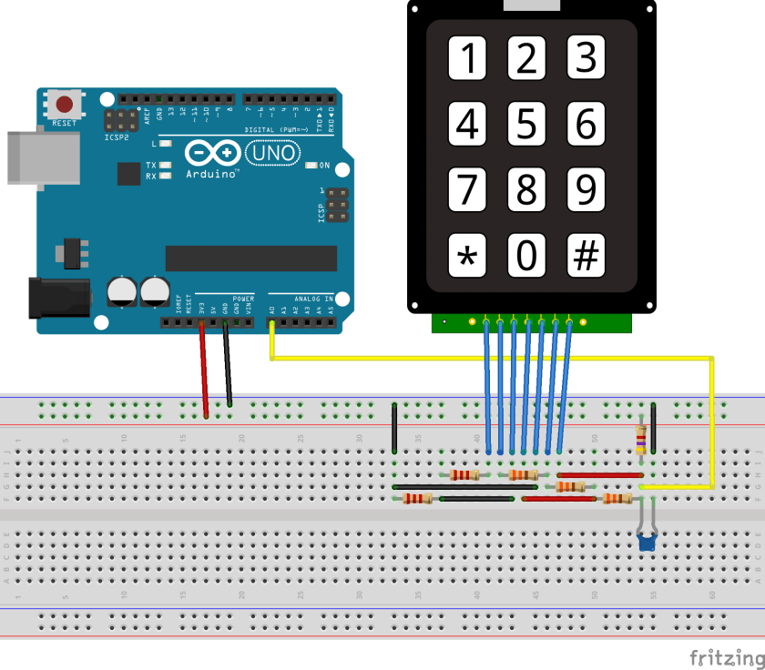
Here is my circuit design for Arduino keypad, using only 1 analog pin (instead of 7 serial pins), 6 resistors (can be reduced to 5) and 1 capacitor: And now for the full story: I decided it’s time …
north stream
It looks like the capacitor just serves as a filter to smooth out the voltage to provide less noise.
south tinsel
north stream
It looks like the capacitor just serves as a filter to smooth out the voltage to...
Okay, thank you! Would I be okay using a much smaller capacitor then? (don't have that exact one)
north stream
The specified one is 0.01µF which is fairly small, not sure what you have on hand.
Realistically however, it's not critical at all and the circuit should basically work even with no capacitor at all, it just might have some noise pickup and occasionally read the wrong key.
livid osprey
north stream
Realistically however, it's not critical at all and the circuit should basically...
If you are okay with a slightly slower response, you could even handle the filtering on the software side...