#help-with-arduino
1 messages · Page 93 of 1
 sweet hedge
Are there any like samples like online ? So i could use it as a reference
 cedar mountain
Not sure offhand... I'd just being doing the same web searches you are. The simplest way to do it might be to just get a cheap Android tablet as the reader.
 young flint
just for a simple switch! thanks for answering 🙂
 finite elk
Does anyone have any suggestions for breadboard wires with the "dupont" connector that are made from silicone?
finite elk
@pine bramble definitely. I got this from Amazon for the grabber leads (which are absolutely terrible) but they come with pretty nice silicone DuPont wires. Goupchn Mini Grabber SMD IC Test Hook Clips 12PCS with Silicone Jumper Wires Test Leads Kit for Electrical Testing 6 Colors https://www.amazon.com/dp/B08S7CPY62/ref=cm_sw_r_cp_api_glt_fabc_RDHAD98KTRJ4FV3Y7KFJ?psc=1
 north stream
@finite elk https://www.adafruit.com/product/4447

These premium female-female jumper wires are handy for making wire harnesses or jumpering between headers on PCBs. They're 200mm (~7.8") long and come loose as a pack of ...
finite elk
@north stream no way! I literally must’ve looked right past those. Gonna make an order, thanks so much! 😀😀😀
north stream
If you want the pin ones, they're here https://www.adafruit.com/product/4482

These premium male-male jumper wires are handy for making wire harnesses or jumpering between headers on PCBs. They're 200mm (~7.8") long and come loose as a pack of ...
And of course https://www.adafruit.com/product/4635

These premium extension jumper wires are handy for making wire harnesses or jumpering between headers on PCBs. They're 200mm (~7.8") long and come loose as a pack of ...
And if you want grabbers, plug 'em into these https://www.adafruit.com/product/401

When alligator clips and even scope probes are too large, IC hooks come to the rescue! These fine clips are very nice, and come in a set of 9 colors (black, brown, red, orange, yellow, ...
finite elk
Looks like the grabbers are discontinued, any other suggestions?
north stream
Oh, that's annoying. There are other grabbers but they don't mate with the jumper wires
The Cal Test "MiniFlex" line are excellent, but not cheap
I think the AdaFruit ones may have been Warwick XK hooks
The E-Z-Hook XKM is also similar https://e-z-hook.com/test-hooks/micro-hook/xkm-micro-test-hook-double-gripper-with-0-025-in-square-pins/
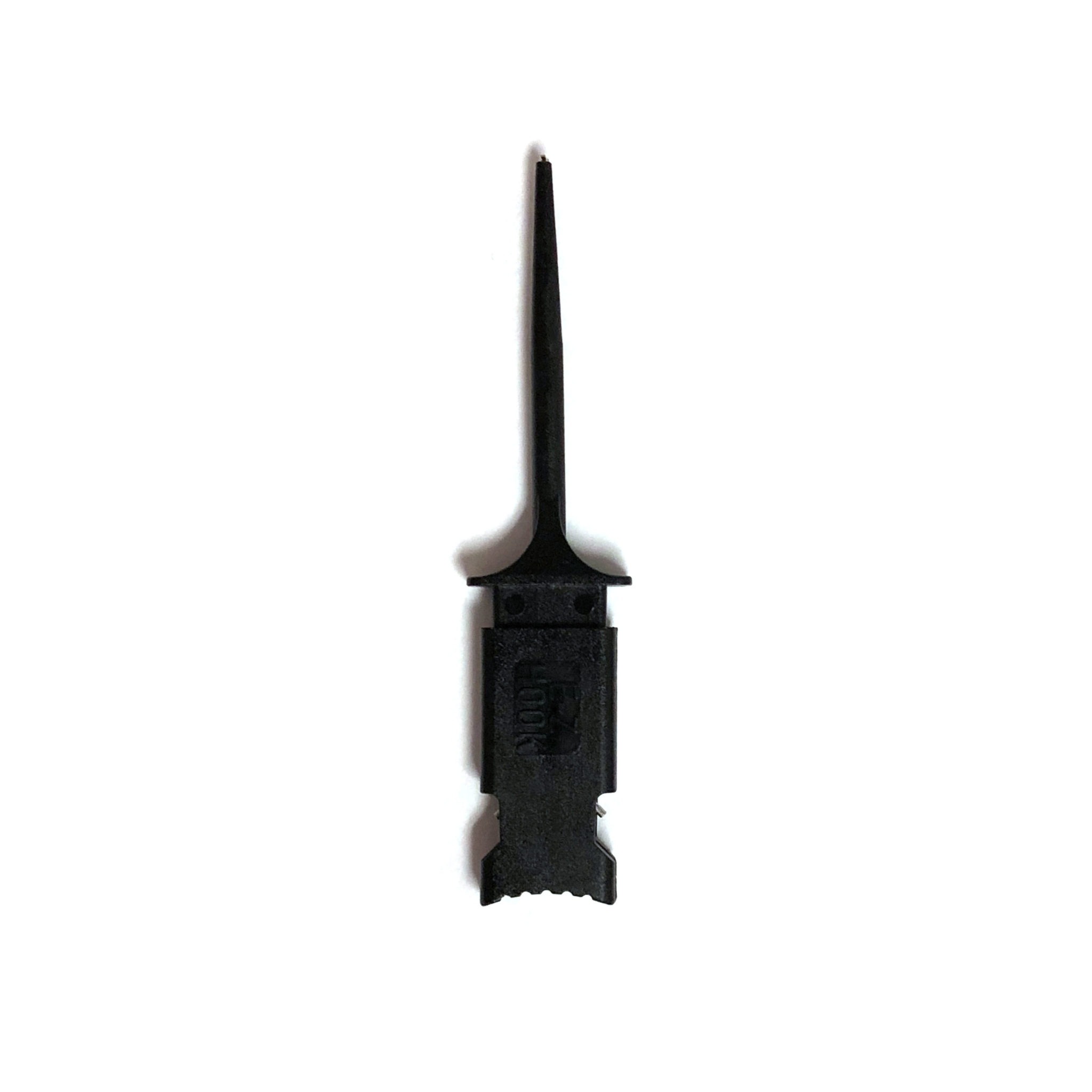
E-Z-Hook, A Division of Tektest, Inc.
The XKM double gripper test hook with 0.025" square pins fits with (2) 0.025" square sockets & the hook fits over components up to a max diameter of 0.050".
finite elk
Those looks great, thanks for the recommendations.
 hollow condor
Has anyone had issues where the device just stops working and you'll need to re-upload the code for the device to work again? Anyway to fix that?
 alpine oasis
Can I connect my powerbunk to my nodemcu(esp8266) using this 5V cable https://aliexpress.ru/item/33049912790.html / male to male usb and hw131 https://aliexpress.ru/item/32637399463.html ? Just when I directly connect nodemcu to powerbunk, powerbunk turning off after some time. Seems it thiks nothing is connected.
Also I have those D-SUN ( https://aliexpress.ru/item/32261885063.html ) things and 3 batteries holder. Maybe I can power nodemcu using them, with some batteries? Also I have XL4015E1.
I need some temporary solution.
north stream
Yeah, the power banks are generally load sensing and turn off the boost circuit it they don't think it's being used. There are power banks that don't do this, or you can just use a dedicated power converter.
Since the nodemcu runs on 3.3V, boosting to 5V and then regulating back down to 3.3V seems unnecessarily complicated and wasteful, you might be better off directly converting your power source to 3.3V.
north stream
Your best bet is to ask your actual question
 wise latch
ahah mb
okay so I'm trying to create a product that's practically is a plant pot that measures water and temp just like any other typical arduino water plant project, I wanted to output the water and temp onto a display and output emotions depending on the plant's health or the use of sound stimulations to possible act as a indicator as well as the display say for example the person using it has a visual problem and coudln't use display properly so they had to rely on sound to check the plant's health
and on top of that i wanted it to use solar panel to charge
is this possible ?
ahah
north stream
Yes, it's possible. For solar power, and since the parameters are unlikely to change quickly, a slow low-power display like eInk might be a good choice. I built something like that once that used a sort of cartoon "face" with some rubber tubing as the mouth, and I used a servo to bend the tubing from "smile" to "frown".
wise latch
ahh sorry in the second seteence whats an 'elnk' aahah sorry, ahh i see could u explain how u used the servo thing? how did that work
did u use a display to display the 'cartoon' 'face'?
im sort of confused on the servo thing? bend a tube? what did u use that for?
north stream
eInk is "electronic ink" or "electronic paper" displays like https://www.adafruit.com/product/4446
Easy e-paper finally comes to your Feather with this Adafruit EInk Feather Friend that's designed to make it a breeze to add an eInk display. Chances are you've seen one of ...
Basically I had the tubing free to move in the middle and anchored at one end with the servo at the other. If I pointed the servo arm down, it would bend the tubing down and back up for a "smile" and if I pointed the servo up, it would bend the other way for a "frown".
No display, just a piece of cardboard with eyes drawn on it and the tubing in front for the movable mouth to change expression.
wise latch
ahh i see!
that's still pretty cool!
hmm
is there anyway i could find smth like this on amazon?
as my rpoject is due in a week i mean i would get it from adafruit but i feel like the delivery might be a couple days ahah
whereas i feel amazon would take about a day or two
north stream
I don't do business with amazon, but you can get AdaFruit products from Digikey with fast shipping
north stream
 cedar mountain
I'm impressed that you refrained from using a "LMGTFY" link there. 😁
 elder hare
i've never used them befor but how can i use beatsin8 or beatsin16 in this code to move the pattern
void StripSettings::Cylon()
{
    for (int i = 0; i < _NumLeds; i++)
    {
        if (((_NumLeds - 1) - i + GeneralSettings.Position) % _NumLeds == 0)
        {
            _Leds.data()[i] = CHSV(Color.Hue, Color.Saturation, GeneralSettings.Brightness);
        }
    }

    fadeToBlackBy(_Leds.data(), _NumLeds, GeneralSettings.Spacing * 5);
}
 pine bramble
;)
@hollow condor No that sounds like a misdiagnosis of the issue. ;)
They don't just stop working, and a reflash of the same firmware restores them to original function.
That'd be awful.
Most project reset properly by cycling power.
The ones that 'remember things' can get stuck, of course.
pine bramble
The code, the part number of the main chip, are what we use to figure things out here. ;)
 past agate
Hi all! How do I estimate the operating time of a device given a battery power capacity if it has 2 operating modes? A low power consumption mode (deep sleep) and a high power consumption mode (active mode)?
I was looking at the adafruit video tutorial on this, but it looks like it was only for one operating mode (probably an active mode) https://www.youtube.com/watch?v=U_Q3djsktQs

Becky Stern gives you tips for choosing the perfect battery solution for your wearable electronics projects: https://learn.adafruit.com/battery-powering-wearable-electronics
Visit the Adafruit shop online - http://www.adafruit.com
Subscribe to Adafruit on YouTube: http://adafru.it/subscribe
Join our we...
north stream
Basically you come up with a guess as to the duty cycle of the two modes and compute an average.
past agate
Oh okay I just average it. Duh lol. Could I use a time unit instead of a duty cycle Thanks! So something like to help me calculate the average current draw:
(I_active * Time_active + I_deepsleep * Time_deepsleep) / (Time_active + Time_deepsleep)
Would that be it?
north stream
Looks right to me
 neat temple
Hi, can someone help me with this?
im trying to use this code to use a webserver...
neat temple
neat temple
Hi, can someone help me with this?
im trying to use this code to use a webserver...
can someone help me? i think it's something very simple but im scratching my head with the javascript and html part
cedar mountain
I suspect people didn't reply because you didn't describe what was going wrong. It's very difficult to just scan a piece of code for any and all possible mistakes, but if you know what it's doing versus what you want it to do, you can more easily zero in on the problem.
neat temple
function updateSliderPWM(element) {
  var sliderValue = document.getElementById("pwmSlider").value;
  document.getElementById("textSliderValue").innerHTML = sliderValue;
  console.log(sliderValue);
  var xhr = new XMLHttpRequest();
  xhr.open("GET", "/slider?value="+sliderValue, true);
  xhr.send();
}
this is a Javascript part to a webserver on a nodemcu, and im just wondering how can i use a html value to return to the javascript part of the script
should i use a class id?
or how i can insert a part to the xhr.open("GET", "/slider?value="+sliderValue, true): to be the specific led channel i want to change
this is the slider in the html part ``` <p><span id="textSliderValue">%WSLIDERVALUE%</span></p>
<p><input type="range" onchange="updateSliderPWM(this)" id="pwmSlider" min="0" max="1023" value="%WHITESLIDERVALUE%" step="1" class="slider"></p>
sorry if im being redundant i hope someone can help
thanks
 glass hound
I'm looking to make my own@pine bramble
 pliant totem
So guys, im planning to datalog 2 power consumption using only 1 arduino nano. Im using this breakout board as the power sensor.
https://www.adafruit.com/product/904

This breakout board will solve all your power-monitoring problems. Instead of struggling with two multimeters, you can just use the handy INA219B chip on this breakout to both measure both ...
Is it possible to read from 2 separate INA219s at the same time?
how do we switch from 1 sensor to the other?
pliant totem
ah yes, thank you
pliant totem
@cedar mountain is there any way to specify which input is which?
how do you initialize the different INA219 boards with the specific addresses
cedar mountain
You physically modify the boards with little solder blobs to set the addresses.
pliant totem
no i mean how do you communicate to it in the program?
cedar mountain
Oh, sorry, typically there's an extra optional address parameter when you initialize the INA219 library.
This shows an example.
pliant totem
alright, thank you
 hallow moss
Hi! I'm trying to send extended advertisements from an adafruit sense using the bluefruit library. l've tried switching the flag in the adv_advanced example and it stopped advertising at all. I've seen that in the softdevice the flag is added, so the feature must be available somehow. Does anyone know how to get it working or if it's even possible to do extended advertising with the library?
elder hare
has anyone in here worked with the HUB75 matrix board and the library ESP32-HUB75-MatrixPanel-I2S-DMA ?
 arctic oracle
Hello guys, I am going to start a new project. I am a mechanical engineer but truely terrible at coding. (copy pasta). I am looking for some (paid) assistance down the road. Anyone interested in earning a couple bucks and helping me out?
hollow condor
Hey guys noticed this issue after I plugged into a Mac and came back home to my windows pc. It worked fine before i plugged into the Mac, worked fine on the Mac but now on my windows pc I received this. Any ideas? The right port, board, programmer has been selected.

 stable forge
arctic oracle
Hello guys, I am going to start a new project. I am a mechanical engineer but tr...
stable forge
arctic oracle
Hello guys, I am going to start a new project. I am a mechanical engineer but tr...
You can post a job at https://jobs.adafruit.com/
Find maker jobs in 3D and CAD, Art, Design, Education, Embedded Development, Engineering, Fabrication, Marketing and Communications, and Web Development
 bitter wyvern
Hey where can i get a documentation for functions in Neopixel library
bitter wyvern
Thanks @stable forge @leaden walrus but i hoped there is something more in depth.
 leaden walrus
in depth how? or, do you have a specific question?
pine bramble
@hollow condor Can't read the text.
bitter wyvern
Problem im having @leaden walrus is that i have rgbw leds and need too turn on/off 9 led at the time at for example firtst 9 then from number 18 etc.
north stream
That's more of a math problem than an LED problem. You could do it with counters or division.
bitter wyvern
Problem is that i can't figure out how to turn on multiple led at once, math easy i figured that one out already.
 candid frigate
Hey guys, I have a simple problem that requires a simple solution, but Im not well versed with hardware. Im trying to create a button for my camera rig that will mimic the shutter on my camera. Basically a half press with trigger auto focus, and a full press will trigger the shutter. I know how to wire it all up, but I dont know what type of button can accomplish this that is also small enough and tactile that it can fit on the side mounts of the rig
 leaden walrus
just realized i linked to the CP lib. here's the Arduino lib:
http://adafruit.github.io/Adafruit_NeoPixel/html/class_adafruit___neo_pixel.html
@bitter wyvern there's really only setPixelColor() for setting one pixel at a time. so you'll want to write a helper function that has a loop.
bitter wyvern
Yeah i hoped that there is some easier way but thanks for the help.
cedar mountain
candid frigate
Hey guys, I have a simple problem that requires a simple solution, but Im not we...
The term you want is a "double action tactile switch".
candid frigate
cedar mountain
The term you want is a "double action tactile switch".
Thanks! Someone had linked me to this, would it do what Im looking for? https://www.digikey.ca/en/products/detail/e-switch/PB300DTQ/6126492?s=N4IgTCBcDaIAoCEDMAGFARAKgRRAXQF8g
cedar mountain
I think, so, yeah.
candid frigate
Im basing the wiring off this

Super simple, but I dont know how that button actually works, though it does have 3 terminals so I hope it works in the same fashion
cedar mountain
One of my managers had the slogan "Hope is not a strategy." 😁 You have the datasheet, so you should probably figure out how it's supposed to be wired.
candid frigate
I am entering uncharted territory here with this stuff haha
I just cant find something to purchase that does what I want
hollow condor
pine bramble
<@!146364543189123075> Can't read the text.
processing.app.debug.RunnerException
at cc.arduino.packages.uploaders.SerialUploader.uploadUsingPreferences(SerialUploader.java:152)
at cc.arduino.UploaderUtils.upload(UploaderUtils.java:77)
at processing.app.SketchController.upload(SketchController.java:732)
at processing.app.SketchController.exportApplet(SketchController.java:703)
at processing.app.Editor$UploadHandler.run(Editor.java:2055)
at java.lang.Thread.run(Thread.java:748)
Caused by: processing.app.SerialException: Error touching serial port 'COM3'.
at processing.app.Serial.touchForCDCReset(Serial.java:107)
at cc.arduino.packages.uploaders.SerialUploader.uploadUsingPreferences(SerialUploader.java:136)
... 5 more
Caused by: jssc.SerialPortException: Port name - COM3; Method name - openPort(); Exception type - Port busy.
at jssc.SerialPort.openPort(SerialPort.java:164)
at processing.app.Serial.touchForCDCReset(Serial.java:101)
... 6 more
This is what it says
Any ideas? The right port, board, programmer has been selected.
 pallid sage
cedar mountain
One of my managers had the slogan "Hope is not a strategy." 😁 You have the da...
pallid sage
cedar mountain
One of my managers had the slogan "Hope is not a strategy." 😁 You have the da...
and hope rx/tx aren't reversed :-)
elder hare
trying to use this spotify icon on this website https://javl.github.io/image2cpp/ to create arduino code for display on matrix but i can't get it to work, i dont know what settings to put in for correct output


i mean if you know it's the Spotify logo you can see it but
north stream
@hollow condor It's right there in the error: "port busy". It seems like something else has that port open.
hollow condor
north stream
<@!146364543189123075> It's right there in the error: "port busy". It seems li...
Any port that I assign the board to has that issue!
It just worked fine on the laptop
But my desktop has this issue
north stream
Make sure you aren't running something like two copies of the program, or software that grabs ports or something.
hollow condor
north stream
Make sure you aren't running something like two copies of the program, or softwa...
Will check
I'll also re-install java
 rough torrent
Is the serial monitor open? In older versions of the IDE it would interfere with uploading - newer versions will just disable the serial monitor while uploading.
Also it might be worth reinstalling a new version of Arduino
 trim pier
Hi,
I need help with the itsy Bitsy nrf52840 express.
Out of the bag, it is detected as a BLE keyboard and prints the alphabet.
I can't upload anything to it though cause on the Arduino IDE it goes timed out with the not-in-dfu error.
I tried pressing the reset button a number of times and no blinky led.
It is recognized as a COM7 on windows 10, Arduino IDE 1.8.10
Any suggestions?
 carmine sun
Hello, I need help with a piece of code for the Adafruit Grand Central M4.
#include <SPI.h>
#include <Tic.h>

TicI2C tic;

void setup() {
  Serial.begin(115200);
  Wire.begin();
  Serial.println("Serial and I2C on");
  delay(500);
  tic.haltAndSetPosition(0);
  tic.exitSafeStart();
  Serial.println("Motor Startup complete");
  delay(500);
  movePulses(200);
}

void loop() {
  resetCommandTimeout();
  delay(10);
}

void movePulses(int pulses) {
  Serial.println("begin movePulses subcommand");
  int runSpeed = 2000000;
  float runTime = runSpeed / 1000 / pulses;
  Serial.print("runTime in ms: ");
  Serial.println(runTime);
  Serial.println("Run");
  tic.setTargetVelocity(runSpeed);
  delayWhileResettingCommandTimeout(runTime);
  Serial.println("Stop");
  tic.setTargetVelocity(0);
  delayWhileResettingCommandTimeout(runTime);
  Serial.println("Turn off");
  tic.deenergize();
}

void resetCommandTimeout()
{
  tic.resetCommandTimeout();
}

void delayWhileResettingCommandTimeout(uint32_t ms)
{
  uint32_t start = millis();
  do
  {
    resetCommandTimeout();
  } while ((uint32_t)(millis() - start) <= ms);
}

void waitForPosition(int32_t targetPosition)
{
  do
  {
    resetCommandTimeout();
  } while (tic.getCurrentPosition() != targetPosition);
}
This code does nothing, not even sends reports back to the serial port. Is it something with my libraries? I don't understand
 jagged void
Quick question! Is this a buffer or a bilateral switch? I know it’s one of them any help please!
 cedar mountain
The chip marking and package is consistent with a TI SN74AHC1G125DB buffer, anyway.
 summer wave
Hey! I'm new to Adafruit and Arduino, and I need to do a project. How would I compare the GPS location from a Adafruit Ultimate GPS Breakout - 66 channel w/10 Hz updates [ADA746] to the GPS location on my phone. How would I go about doing this?
cedar mountain
summer wave
Hey! I'm new to Adafruit and Arduino, and I need to do a project. How would I co...
It's not quite clear what you're asking... are you looking for a formula to calculate the distance between two sets of GPS coordinates, or looking for help in printing out the coordinates from either the breakout board or your phone?
summer wave
I would like to access both sets of coordinates on my phone, and calculate the distance between them
cedar mountain
Gotcha. The breakout board is intended to talk to things like microcontrollers instead of to phones, so there would be a bit of virtual glue necessary there. For instance, you could use one of the BLE Feather boards to read the coordinates from the GPS breakout and send them to the phone via Bluetooth, which would let you physically separate the two by a short distance as well.
 vivid rock
was experimenting with TinyUSB library to make my board appear as external USB drive on the computer, and at some moment my computer gave me this message
Please insert a disk in USB drive D
leaving me speechless 🙂
I got it working, of course
 stark mist
hello, what is the easiest way to copy a file from my pc across to an nrf52 feather sense running an arduino sketch?
I must be missing something because I'm sure this must be trivial for things like graphics in projects but I must be missing something easy
vivid rock
It is actually not that trivial. TinyUSB library is your best bet for Arduino sketches; for Circuit Python it is easier
stark mist
yeah circuit python I get the drive and I just copy the file across, done
I'll check out tinyUsb
thank @vivid rock
you
@vivid rock awesome well that was easier than I thought when I read your reply thanks that is exactly what I needed, got the usb mass storage device showing up with the location for the files and I can even see my sensor calibration file that I saved out from a different sketch so I know its the right location / flash ect thanks
I wonder if I can make that a user option to boot into mass storage mode, so the user flips a switch, plugs the device into the usb on pc and they get the mass storage - else its going to run my regular sketch code which needs to read a file from the flash and so some pixel stuff, so this would be an easy way for the user to be able to plug it in and upload a new file
vivid rock
Yes, you can. I did that in one of my projects - the sketch checked if zome pin waz pulled high or low at startup, and depending on it either went into mass storage mode using tinyusb, or dan the default sketch
If you want i can share the code
stark mist
all good I think I'm there
just about to compile
just gonna use the built in user button on the board for testing right now
 random crown
I'm not sure if this is the correct place to put this question, but I'm trying to document one of my arduino projects (arcade button push to talk button i presented at show and tell a few weeks ago) using fritzing, and the led microswitch isn't available in the adafruit fritzing items.
This is the part that contains the LED microswitch i'm refering to: https://www.adafruit.com/product/1185
It doesn't seem like it's the same thing as a microswitch + LED, since i use all 4 spade connectors to have the button normally open, but have the light go off when the button is pressed.
Anyone know of a proxy part I might be able to use?

OMG WATCH OUT! This 100mm diameter arcade button with a 10mm deep plastic base is so massive and inviting it may collapse upon itself and form a black hole from which not even light can ...
 real abyss
anybody done any work on making music with stepper motors?
I've got some steppers and a motor shield but in a way I wonder if the motor shield has abstracted the work for me too much
 shy bluff
anybody done any work using stepper motors pushing a plate against a switch?

like this?
north stream
The motor shield has a separate PWM chip running the stepper drivers, which could make it harder to make stepper music (if you plan to send each pulse explicitly, you'd have to do so via I2C), or easier (if you can harness the PWM generator to make the musical tones for you automatically)
real abyss
^ interesting
 unborn frost
hey, I am working with the keyboard library with a pro micro and I am trying to store key values in an array for example: KEY_LEFT_CTRL but I need to know what datatype they are to store them in the array and I cant find that info anywhere. So does anyone know the type?
Nevermind, int works
 heavy basin
I am new to electrical engineering, I am already proficient at C++ and I would like to increase my understanding of hardware.
I currently only know the basics (what current/resistance/potential difference is), and I have made a small list of parts to buy to get started with Arduino
Here is the list of parts, I did a bit of research and ended up with these, but I'm not sure about how many ohms the resistors, etc should be, and what battery I should use.
Arduino Uno R3
ESP8266
Breadboard
Jumper Wires
USB Cable
Resistors (do more research)
Diodes (do more research)
Transistors NPN (do more research)
LEDs (with resistors)
RGB LEDs common cathode
LCD
Speaker
Piezo Buzzer
Motor
Servo
Variety of buttons and switches
Potentiometer (do more research)
Force sensor
Tilt sensor
Photoresistor
Analog Temp Sensor
Ping/Distance/Range sensor
Passive Infrared (Motion) Sensor
I'm not sure if I'm missing something, or if I have added something that won't work, and the amount of units the diodes, resistors and transistors should have, I hope someone can help me with this.
It would also be nice if I could have some resources to help me understand electrical engineering better
real abyss
Seems like I could just set the frequency on the motor, then call the steps x how long the note should be
Then reset the frequency
I'm trying to decipher how this driver works, heh
pallid sage
heavy basin
I am new to electrical engineering, I am already proficient at C++ and I would l...
a couple PNP transistors are probably good to look at too, useful resistor values vary, I'm not very experienced, but in many cases it depends on what a formula says in a situation, also forgot capacitors
there are some starter kits on your favorite warehouse labor violation sales site, though I had trouble settling on what specifically to recommend last time it came up
if you want to come from a software angle theres also the circuit playground that adafruit sells
heavy basin
Yeah I am looking at starter kits but unfortunately there doesn't seem to be anything that's decent here, and I am unable to order anything from China, I'll do more research about PNP transistors
pallid sage
kinda the inverse of npn, turn it on to stop the flow, also ?stuff flows from the emitter to the collector?
north stream
@heavy basin Popular resistor values are 10k (for voltage dividers, pullups, pulldowns, etc.) and a lower value (330Ω - 1k) for current limiting for driving bipolar transistors, LEDs, and similar items. PNP transistors do the same sorts of things as NPN transistors, but with opposite polarity. Often NPN transistors are used to pull current to ground, and NPN transistors are used to source current from a power supply. You might also look at MOSFET transistors. One excellent resource is "Learning the Art of Electronics", which is basically the book from a one-month course on learning electronics. It's based on "The Art of Electronics", a much more thorough and in depth book.
 raven sandal
north stream
<@629349827649601558> Popular resistor values are 10k (for voltage dividers, pul...
raven sandal
north stream
<@629349827649601558> Popular resistor values are 10k (for voltage dividers, pul...
"Often NPN transistors are used to pull current to ground, and NPN transistors are used to source current from a power supply."
Did you mean PNP for one of those?
north stream
Yes, I meant PNP for the second one, I goofed.
elder hare
anyone here worked with ESP32-HUB75-MatrixPanel-I2S-DMA ? 🙂
candid frigate
How difficult would it be to wire up 8 lights that turn on in a sequence with a dial, with the previous light turn off when the next light turns on?
elder hare
im using ESP32-HUB75-MatrixPanel-I2S-DMA library that also uses Adafruit GFX and i was wondering is there any way to rotate a shape (a square or triangle that is drawn on the HUB75 Matrix)?
north stream
@candid frigate There are a few ways to approach stuff like that. It's not too hard, and the amount of effort varies with what kind of lights and how you're controlling them.
candid frigate
I suppose since each light is in a sequence, pushing a button could trigger the next light
north stream
The easiest way might be to use an 8-position rotary switch and hook a light to each position. But that may or may not be what you want. Another way is to use a potentiometer, microcontroller, and addressable lights. Then the wiring is trivial and the switching logic becomes software.
candid frigate
Yeah I was looking at the 8 position rotary switch, would probably be the easiest, but the shipping time I found on a piece was too long
north stream
I suspect DigiKey carries them, they have quick shipping
hollow condor
Hey guys, I'd like to know if I can use the Arduino without a laptop? Like once I've uploaded a sketch, is there a way to just make it work by adding a power supply?
Or will I have to use a raspberry pie? I noticed my uno has a power supply port next to the usb, is there a way that I just plug into that power supply and it acts on its code?
cedar mountain
Sure, that's very possible. Arduinos have on-board flash memory in the microcontroller, so they can boot from that instead of loading a program over USB.
hollow condor
cedar mountain
Sure, that's very possible. Arduinos have on-board flash memory in the microcont...
I figured! How do I go about doing this? Do I just upload a sketch, remove the usb and add a power supply?
cedar mountain
Pretty much, yep. It may be easiest to use something like a USB charger or battery pack, but there's also a separate VIN power supply you can use, which takes 7-12V on the Uno.
hollow condor
cedar mountain
Pretty much, yep. It may be easiest to use something like a USB charger or batte...
Awesome thank you so much!! How about for the pro micro?
Also I'll involve a little more details, these are supposed to be as part of an art installation, and they'll need to be powered everyday for 8 hours, for a whole month, can I run into random issues?
cedar mountain
I think the Pro Micro will have a VIN pin rather than a connector, and it may take 7-9V there instead, so again a USB charger might be easiest.
hollow condor
cedar mountain
I think the Pro Micro will have a VIN pin rather than a connector, and it may ta...
Thanks will check it out
cedar mountain
Powering them for long periods should be fine. The only slight thing to watch out for is that eventually the millisecond timer will overflow (after something like 45 days, I think), which sometimes code doesn't always elegantly handle.
hollow condor
cedar mountain
Powering them for long periods should be fine. The only slight thing to watch ou...
That should be fine, what about sudden power outages?
Would that do anything to the memory once the power is back?
cedar mountain
That's no problem. They don't have to be safely shut down like a PC or anything. They'll just boot right back up when they get power back.
hollow condor
Awesome m8 thank you so much you've helped a ton, and also if it's alright, can I dm you in case this space is crowded when I have another issue?
cedar mountain
Sure, although generally "the channel" will be more active and informed collectively than I will be individually. 😁
hollow condor
Sure hahaha both @north stream and you have helped a ton :D
cedar mountain
Indeed, we have a number of great folks like him around. 👍
north stream
I had an issue with my water heater and wanted to figure out whether it was one of the switches or a heating element or what, so I wrote a simple Arduino sketch to monitor the temperature and which elements were powered and write the results to an SD card. Naturally, once I had instrumented the heater, it refused to show the issue for a few weeks. So I had that Arduino code running continuously for about a month with no problems.
elder hare
im still blank xD
hollow condor
north stream
I had an issue with my water heater and wanted to figure out whether it was one ...
Awesome thanks
hollow condor
north stream
I had an issue with my water heater and wanted to figure out whether it was one ...
Also, do you use a clone or genuine?
north stream
I've used both, I don't really remember which I used for that project.
I dug up a picture of it, and it's one of the small breadboardable ones, so probably a clone of some sort

 green heath
Oh the wires
I still havent found a solution to the wire spider that seems to always pop up
north stream
Yeah, that's kind of a slapdash build for a one-off use. It sat there like that for a few weeks and worked fine
Made this graph from the resulting log
 elder hare
Reposting as it got deleted hihi
so im working with a 16x32 HUB75 matrix display using ESP32-HUB75-MatrixPanel-I2S-DMA Lib (that also uses Adafruit GFX Lib)!
im totally stupid when it comes to math seriously but how can i rotate this basic red line that i draw on the screen
dma_display->writeFastHLine(x, y, 5, dma_display->color444(15,0,0));
If you want a 5-pixel line starting at (x, y), the other end of the line would be at (x + 5 * sin(angle), y - 5 * cos(angle)), with the angle measured clockwise from vertical.
elder hare
that would only rotate once right? or am i totally wrong?
i want to rotatet the line over and over again make it spin 360 around
cedar mountain
Then you'd need to make an animation loop to draw the line, erase it, draw it in a new position, etc.
elder hare
  int angle = beatsin8(30, 0, 180, 0, 0);
  int oldX = 8;
  int oldY = 8;
  int newX;
  int newY;

  newX = oldX * cos(angle) - oldY * sin(angle);
  newY = oldX * sin(angle) + oldY * cos(angle);

  dma_display->fillScreen(0);
  dma_display->writeFastHLine(newX, newY, 5, dma_display->color444(15,0,0));
this is not right but fun to watch xD the line is "dancing" in a circular fashion xD
what am i doing wrong?
cedar mountain
The writeFastHLine() function only draws a horizontal line. You'd want a different function which can take (x, y) coordinates for both ends of the line.
Also, it's not quite clear why you're mixing sines and cosines together like that.
elder hare
maybe this one void Adafruit_GFX::writeLine(int16_t x0, int16_t y0, int16_t x1, int16_t y1, uint16_t color) ?
north stream
Yes, the GFX library already contains functions to draw lines from point to point
elder hare
it's funny tho drawFastHLine basicaly just uses writeLine
void Adafruit_GFX::drawFastHLine(int16_t x, int16_t y, int16_t w,
                                 uint16_t color) {
  startWrite();
  writeLine(x, y, x + w - 1, y, color);
  endWrite();
}
ok so using dma_display->writeLine(); what else am i doing wrong?
vivid rock
I have a problem...
I am writing an Arduino library which uses FastLED library internally. E.g., I have a class with constructor which looks like
POVstaff::POVstaff(uint16_t n)
    :numPixels(n){
        FastLED.addLeds<LED_TYPE, COLOR_ORDER>(leds, n).setCorrection( TypicalSMD5050 );
    }
here is a problem. I would like to be able to use different LED types and color orders. However, I can not pass it to my constructor as parameters: FastLED requires these to be constants - if I do
POVstaff::POVstaff(chipset LED_TYPE, uint16_t n)
    :numPixels(n){
        FastLED.addLeds<LED_TYPE, COLOR_ORDER>(leds, n).setCorrection( TypicalSMD5050 );
    }
it complains
The only thing I can do is use #define macros to define LED_TYPE, COLOR_ORDER
but then, I need to define it inside my library, not inside a sketch that uses my library.
Is there a good solution to this problem?
elder hare
@cedar mountain @north stream i got it to work
  int angle = beatsin8(5, 0, 360, 0, 0);
  int oldX = 8;
  int oldY = 8;
  int newX;
  int newY;

  newX = (oldX + 5 * sin(angle));
  newY = (oldY - 5 * cos(angle));

  dma_display->fillScreen(0);
  dma_display->writeLine(oldX, oldY, newX, newY, dma_display->color444(15,0,0));
but only by using a beatsin8 on the angle tho :S
now the question becomes how to rotate a square
elder hare
  int angle = beatsin8(5, 0, 90, 0, 0);
  int oldX = 5;
  int oldY = 5;
  int newX;
  int newY;

  int xCenter = (oldX + newX) / 2;
  int yCenter = (oldY + newY) / 2;

  newX = (oldX + 5 * sin(angle));
  newY = (oldY - 5 * cos(angle));

  dma_display->fillScreen(0);
  dma_display->drawRect(xCenter, yCenter, dma_display->width() / 2, dma_display->height() / 2, dma_display->color444(15,0,0));
well, it's moving in a circle but not "inplace" like i want to :/ what am i doing wrong?
 opaque matrix
elder hare
```c++
int angle = beatsin8(5, 0, 90, 0, 0);
int oldX = 5;
int oldY = 5;
...
opaque matrix
elder hare
```c++
int angle = beatsin8(5, 0, 90, 0, 0);
int oldX = 5;
int oldY = 5;
...
I had to deal with a similar issue to this a couple of years ago when I was trying to rotate some functions around their turning point. The way I got it working is using some linear algebra with matrix transformations that would first rotate the shape around (0,0) then move it to the correct position meaning it will look like it rotates around itself. If you want I could try writing some code to do it if you don’t understand how the maths would work for it.
elder hare
im totally stupid when it comes to math 😐 so yea! please feel free todo so! and i'll try with my crap xD
@opaque matrix
opaque matrix
Once I get my computer on I will give it a go
elder hare
do you have a matrix display also? 🙂
opaque matrix
No but I will write all the maths part of it and do some testing by printing out the points and putting them into a graphing calculator
 north stream
I did some code recently that supports rotation and translation https://youtu.be/-WXi1IAnEqw
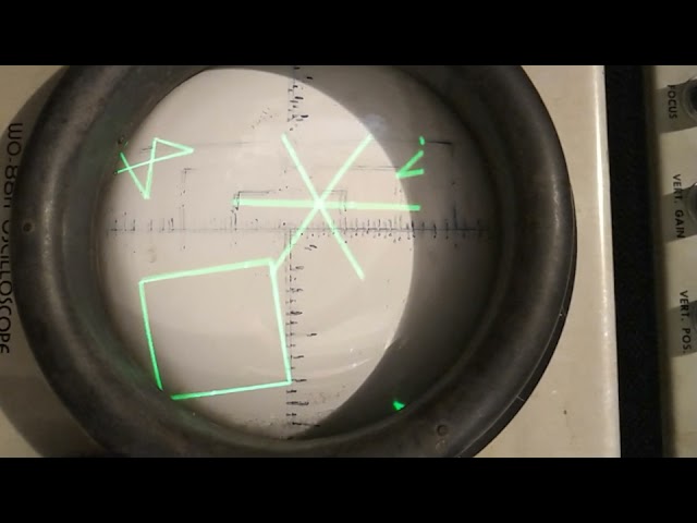
After restoring an old oscilloscope, I programmed a microcontroller to generate graphics for it to display
elder hare
@north stream cool
 gusty mortar
I just wanted to drop this here and say thanks to those that helped me here. Let me know what you think 🙂
https://github.com/D34G/SamdAudioSD

GitHub
Audio library for Atmel SAMD series Arduino Family of microcontrollers. Tested on the Nano 33 IoT. - D34G/SamdAudioSD
unborn frost
hey, so i recently learned how to use structs but I have a question. is there some way to use a string to access and attribute of a struct and not have to predefine it in code? for example a struct with 2 int attributes "k1" and "k2". could I use a string to change the value of k2 without in code typing structname.k2 = "newvalue"?
I would do something like changeattr(structname, "k2", "newvalue"). is there a capability to do that?
cedar mountain
The general term for this is "introspection" of data structures. It's supported in Python, for instance, but I'm not aware of a good way to do it in C/C++ structs, since the compiler basically drops the actual attribute names and just goes by the byte offset of the variables instead.
You would need to have a more explicitly string-indexed data structure like a key-value map.
unborn frost
alright, I really miss python lol. thanks
 reef pollen
Does anyone know if there's a way to force the Tx pin low?
Pro Micro, hardware serial Serial1, pins 0&1. Tx is usually high to indicate ready, which is fine, but I'm working with a MCP2003 LIN Bus transceiver. Tx high = Transmit mode, Tx low = Transmitter off mode. (and I want to use transmitter off mode)
I'm afraid if I just do digitalWrite(TX_PIN, LOW); that it will be overwritten by Serial1, or it won't work.
ahh. I think I found my answer: apparently, digitalWrite(TX_PIN, LOW); works and overrides Serial, but you have to remember to set it back to HIGH before you transmit again. This is helpful when putting the arduino to sleep/standby, so the Tx pin doesn't stay high and draw extra current!
 shadow marlin
unborn frost
hey, so i recently learned how to use structs but I have a question. is there so...
shadow marlin
unborn frost
hey, so i recently learned how to use structs but I have a question. is there so...
Normally you would use a different data type for this, either a "dictionary" (advanced) or an "association list" (less advanced?).
You could make a lookup table {"k1", "k2","k3"} and use that to make a function String -> int index where the string is found in the array. If all of your values are the same type you could then store them in an array and use this number to figure out which one to change. there's plenty of potential for improving but this method is simple and works.
 craggy gale
Hello everyone. I am trying to use the ESP32-S2 feather with the Adafruit Bluefruit LE UART Friend using Arduino. I had no trouble using a Feather M0 adalogger with this bluetooth module, but now the begin function (of the Adafruit_BluefruitLE_UART class) always returns false during the initialization of the module. Is this due to a difference in cores, SAMD vs ESP32, or something completely different? Is the bluetooth module compatible with the esp32-s2, or is it a lost cause? Thank you for time.
pine bramble
Hi! Do you know what happened to ESP-S2 Arduino support package? It's not available on GitHub
 potent mauve
hi i got a new esp 32 from amazon
it is not getting code uploaded to it
have tried changing the upload speed to 115200 and holding the boot button while uploading
https://www.amazon.in/Easy-Electronics-Development-Bluetooth-Consumption/dp/B07TYCFX5C/ref=sr_1_3?dchild=1&keywords=esp32&qid=1617554078&sr=8-3
i have currently selected ESP32 Dev Module
how can i fix this?
pine bramble
potent mauve
hi i got a new esp 32 from amazon
it is not getting code uploaded to it
have tri...
does the Arduino IDE say code uploaded?
craggy gale
Espressif suddenly pulled all arduino support for the ESP32-S2 from github I think a few days ago, but I think some guy made an achieve of all the stuff on github somewhere.
pine bramble
craggy gale
Espressif suddenly pulled all arduino support for the ESP32-S2 from github I thi...
Its call idf master now
https://github.com/espressif/arduino-esp32/tree/idf-master

GitHub
Arduino core for the ESP32. Contribute to espressif/arduino-esp32 development by creating an account on GitHub.
pine bramble
craggy gale
Espressif suddenly pulled all arduino support for the ESP32-S2 from github I thi...
Follow this steps for installing the idf master
https://www.mischianti.org/2020/12/01/esp32-s2-pinout-specs-and-arduino-ide-configuration-1/
pine bramble
craggy gale
Espressif suddenly pulled all arduino support for the ESP32-S2 from github I thi...
S2 is still unstable for Arduino IDE but it works
vivid rock
they made a new release containing support for esp32s2 literally in the last hour
and killed idf-master branch
pine bramble
vivid rock
they made a new release containing support for esp32s2 literally in the last hou...
O you gotta be kidding me
vivid rock
🙂
actually, I mis-spoke. No new release yet - but they done a massive update, saying it is for version v2.0.0 which now officially supports esp32s2:
https://github.com/espressif/arduino-esp32/commit/5502879a5b25e5fff84a7058f448be481c0a1f73
craggy gale
vivid rock
they made a new release containing support for esp32s2 literally in the last hou...
Espressif releasing update hours after I bought a bunch of new microcontrollers from adafruit to replace ESP32-S2. Well, I guess more business for adafruit is good😁
 jovial dagger
Hi folks, probably a classic newbie question but couldn't find the answer in the forum. Topic is: Metro Mini not showing up as a port. Status:
- bought 6 Metro Mini's from Digikey, all power up and show run the LED flash sequence
- checked that I have a real USB mini cable (all pins visibel at mini side)
- Am running Mac OS 11 - Big Sur
- Arduino Uno's show up fine
- Installed the SiLabs driver, installer says success
- tried the troubleshooting guide, created an info.txt status but can't tell what it means.
- when I plug in the Metro mini, it powers up but nothing in /dev/cu*
Any ideas?
craggy gale
It could be because of faulty USB ports, because USB ports after a while get loose and lose proper connection, even though it would still power the board. But I doubt it is the case here since u have 6 and they are probably pretty new.
jovial dagger
same ports work fine plug-n-play with Uno's..
 wraith current
@unborn frost try arduino map library
 modern seal


Need a little help with my DMX shield that I just got in the mail... wondering what I am doing here wrong... I think I have the pins correctly selected.
Dmx out Jack on the shield to the dmx in on my fixture.


The fixture is set to channel 1, and I am using the DMXSimple library to send 1c255w and 5c255w.... but it is not working... it's got to be something underneath my nose... anybody have any suggestions?
 cinder sonnet
Beginner question. Is the Weller 70w a good soldering iron kit to start out with? I'll be getting my first arduino in the next few days, but having trouble understanding what makes a good iron "good". Any advice is appreciated.
cedar mountain
The WE1010NA? Yep, that's perfectly respectable. The main dividing line for a beginner iron is to actually have temperature control as opposed to just something which plugs in and heats up to whatever.
stark mist
I keep hitting a problem with my nrf52 feather sense using arduino, specifically when I'm using the 'Adafruit_USBD_MSC' to expose the flash memory as a mass storage device, its happened three times now where I'm doing some file operation in windows that looks like it completed successfully, like copying a file or removing a file, then the next time I reset the board using the enable pin - windows immediately flags the MSD as un-formatted and then when I try to use the FatFS to inspect the flash I've lost the files that I added there.
I even tried the windows safetly eject hardware option and it did the same thing. I'm not sure what is going on but the only way to get this back that I've found is to drop the circuit python uf2 onto it,
I tried using the format flash sketch example and it didn't help
stark mist
Okay I managed to get it back
but the files are toast
used the 'SdFat_Format' sketch to format it and then the 'msc_external_flash' sketch to mount it
any idea what might be causing the issue where I some how corrupt the flash?
hollow condor
@cedar mountain hey buddy, this is regarding our last conversation about powering an Arduino with a usb adaptor. I wanted to know it's ideal specifications, I have a 5V 1A adaptor would that do? I'm using the Arduino to control stepper motors, and the driver has a seperate 12v input.
north stream
Should be fine.
cinder sonnet
cedar mountain
The WE1010NA? Yep, that's perfectly respectable. The main dividing line for a be...
Okay awesome. Thank so much Ed. Ya that's the model I was looking at. All I need to pull the trigger. I do realize this is 101 and I am researching plenty, but is there a general temperature range to operate for most electronics jobs?
hollow condor
north stream
Should be fine.
Thnks
cedar mountain
cinder sonnet
Okay awesome. Thank so much Ed. Ya that's the model I was looking at. All I need...
Roughly 350C is a good starting point. Adjust a little lower for leaded solder and maybe a little higher for lead-free, since the melting points are slightly different.
cinder sonnet
cedar mountain
Roughly 350C is a good starting point. Adjust a little lower for leaded solder a...
Amazing. And you think .031 is a good diameter to start? I'm researching right now, but haven't sorted what is good for general DIY electronics.
Or recommended brands to favor?
cedar mountain
Yep, that's fine for general-purpose use. If you're mostly doing large through-hole parts, you can go thicker, and if you're mostly doing fine-pitch surface-mount, you can go thinner. Kester is a well-known brand, for instance, but I generally haven't seen much difference with generics either. You definitely want rosin-core instead of solid-core, though, since that includes flux in the solder, which cleans away the oxidation layer from the metal to let things bond to the real material surface.
Another good item to pick up is some solder braid, which is flat woven copper strands to wick up excess solder if you get a short between pins.
cinder sonnet
cedar mountain
Yep, that's fine for general-purpose use. If you're mostly doing large through-h...
This is so helpful. Thank you. I did land on rosin-core. And I'll get solder braid on your rec. I'll take a look at the generic spools. I guess I won't know what size solder I need until I get into it. So thinking .031 is a good start point. If I were to start using my Arduino Uno w/ these touch switches, think I'd benefit from thinner? https://www.amazon.com/gp/product/B08GBYCG52
cedar mountain
Nah, 0.031 is fine for that. You're in good shape. 👍
The thickness of solder doesn't matter a ton, since it's just a matter of what length of it you need to feed in to produce the same solder blob size that you want.
cinder sonnet
Ah okay cool. I appreciate the help @cedar mountain. Have everything i need to get going!
 proven mauve
Hey there. Anyone messed with the debugging in IDE 2.0? I'm wondering if I can do it. I have an Atmega 32U4 on a breakout board with all the pins available, and an st-link v2. I understand the principles of the debugging (hook up st-link to chip, have break points in code, read variables etc using the IDE) but some of the specifics are not very quick to find. Like which pins I need to be hooking up to...
hmm, looks like it's TDI, TDO, TMS, and TCK
proven mauve
but... I think the st-link has only 3 of those...
pine bramble
i'm getting these kind of error whenever i try to run any code, Blink sketch works fine but other than that, nope
im using esp32

//-------Config
const char* ssid = "Net_Apna_Apna";
const char* password = "ThisThis!77";

void setupWifi(){
  delay(100);
  Serial.println("Connecting to ");
  Serial.print(ssid);
  WiFi.begin(ssid, password);
  while(WiFi.status() != WL_CONNECTED){
    Serial.print(".");
    delay(100);
  }
}

void setup()
{
Serial.begin(115200);
setupWifi();
}

void loop()
{
Serial.print("looping");
}```any help would be very appreciated
proven mauve
So... it looks like these little st-link v2 thumb dongles only support SWIM, and that the atmel chips don't. It looks like I have to buy a JTAG interface. But the information is really spotty. Judging by the datasheet tho, it's JTAG only for IDE 2.0 to the 32U4 for debug, and not these other SWIM pins I have here....
 wet crystal
So I unsoldered that from the 433mhz relay box my switches came, but it seems like it doesn't output data to the arduino could it be due to me powering the chip with 3.3v as it can't take 5v or do I maybe need to unsolder the other IC

Such a nice blurry photo :lul:
jovial dagger
modern seal
The fixture is set to channel 1, and I am using the DMXSimple library to send 1c...
maybe rent a cheap dmx controller and play with the lights so you know they are working as you expect?
stark mist
Questions regarding Arduino C++ - is it better to allocate on the heap or on the stack? how can I find out what my allocation limits are?
What would an allocation failure look like?
Also I often end up in situations where I can no longer upload sketches to the board: it tells me the com port cant be opened its busy or the device isn't in dfu mode?
cedar mountain
stark mist
Questions regarding Arduino C++ - is it better to allocate on the heap or on the...
Typically the heap (or optionally global / static memory) would be used for long-lived variables that persist for the lifetime of the program. Stack variables would be used for things that are only used within a single function, so the memory can be reused when other functions are called.
stark mist
cedar mountain
Typically the heap (or optionally global / static memory) would be used for long...
is there a way to debug how much I've allocated and how much space I have available at any given point?
I hit an error that printed out when I enabled the level 1 debugging that seemed to suggest that malloc failed during the loop
stark mist
cedar mountain
Typically the heap (or optionally global / static memory) would be used for long...
are there any trade off's with global static versus the heap apart from the pointer checking and other general coding things, or are these essentially the same considerations I would use in regular c++ for any other application?
I guess I'm just wondering if there is anything arduino specific about dynamic memory allocation that I need to be aware off. As well as better ways to debug my memory usage.
cedar mountain
The main difference is that on a desktop, there's a virtual memory system, so there's some flexibility about how the heap is managed. On an embedded system, it's direct access to RAM, so the heap can end up fragmented over long periods if stuff is malloced and freed in different orders. For that reason a number of embedded projects just use the heap for allocation during initialization, but try not to fiddle with it during the main application loop.
I'm afraid I'm not too familiar with the Arduino framework, so I'm not sure whether it exposes things like free-space query APIs.
cedar mountain
Heh
stark mist
<code>
Upgrading target on COM16 with DFU package C:\Users\JOHNMI~1.QUI\AppData\Local\Temp\arduino_build_388051\Zero.ino.zip. Flow control is disabled, Single bank, Touch disabled
Failed to upgrade target. Error is: Serial port could not be opened on COM16. Reason: Cannot configure port, something went wrong. Original message: OSError(22, 'The semaphore timeout period has expired.', None, 121)
Traceback (most recent call last):
File "nordicsemi\dfu\dfu_transport_serial.py", line 113, in open
File "site-packages\serial\serialwin32.py", line 31, in init
File "site-packages\serial\serialutil.py", line 240, in init
File "site-packages\serial\serialwin32.py", line 78, in open
File "site-packages\serial\serialwin32.py", line 222, in _reconfigure_port
serial.serialutil.SerialException: Cannot configure port, something went wrong. Original message: OSError(22, 'The semaphore timeout period has expired.', None, 121)
During handling of the above exception, another exception occurred:
Traceback (most recent call last):
File "nordicsemi_main_.py", line 294, in serial
File "nordicsemi\dfu\dfu.py", line 235, in dfu_send_images
File "nordicsemi\dfu\dfu.py", line 157, in _dfu_send_image
File "nordicsemi\dfu\dfu_transport_serial.py", line 115, in open
nordicsemi.exceptions.NordicSemiException: Serial port could not be opened on COM16. Reason: Cannot configure port, something went wrong. Original message: OSError(22, 'The semaphore timeout period has expired.', None, 121)
Possible causes:
- Selected Bootloader version does not match the one on Bluefruit device.
Please upgrade the Bootloader or select correct version in Tools->Bootloader. - Baud rate must be 115200, Flow control must be off.
- Target is not in DFU mode. Ground DFU pin and RESET and release both to enter DFU mode.
last question lol
how do I resolve this?
I probably get about 3 or 4 uploads to the board before I end up hitting this issue and I generally have to restart my pc
stark mist
okay I found the help page and double reset puts it in dfu mode
yay
back up and running
shadow marlin
code blocks: use triple backticks at the start and end. or https://pastebin.com is convenient
 crystal fossil
I am not entirely sure if this is the best channel to ask this in, but I have been trying to figure out the best way to send data from my HUZZAH32 Feather to a remote webpage, not hosted on my network. All I need it to do is sent a variable to the webpage, which will be displayed on the page. Can anyone provide recommendations or ideas? Feel free to @ me. (If it is useful, my website is hosted on repl.it)
proven mauve
@crystal fossil probably something like this: https://randomnerdtutorials.com/esp32-http-get-post-arduino/
crystal fossil
proven mauve
<@!690196776136736889> probably something like this: https://randomnerdtutorials...
Ok, thank you! I will look into that.
 wet siren
how can i control the speed of a dc motor connected to an hbridge chip controlled by my arduino uno
 lilac spade
Hello! For my school project I would like to build an Arduino weather station which would display just basic sensor values on the lcd display. I have the bmp280 sensor and the same display as is shown in this tutorial I think. https://simple-circuit.com/arduino-bmp280-sensor-lcd/ But I am unable to get it to work as my display just stays blank when trying to upload the code to the arduino. My arduino is the nano version with the old bootloader. Any help would be greatly appreciated!

How to connect BMP280 barometric pressure and temperature sensor with Arduino. Values are sent to serial monitor and displayed on 1602 LCD. Arduino BMP280.
leaden walrus
@wet siren this guide might help:
https://learn.adafruit.com/adafruit-arduino-lesson-15-dc-motor-reversing
wet siren
ok thanks
leaden walrus
@lilac spade i'd suggest first verifying the display hardware. figure out exactly what it is and see if you can get a basic example to work. ignore the bmp280 for now.
lilac spade
1602 it says
north stream
That's just the display size (16 columns and 2 rows). The display itself is likely an ordinary HD44780 type display: there's a nice LCD library that works with them.
 rustic dagger
lilac spade
Hello! For my school project I would like to build an Arduino weather station wh...
rustic dagger
lilac spade
Hello! For my school project I would like to build an Arduino weather station wh...
You can start with an example for 1602 LCD to make sure that LCD works and connected properly.
you can try this: https://www.arduino.cc/en/Tutorial/LibraryExamples/HelloWorld
then you need to check the BMP280 sensor by using an example from Adafruit BMP280 Library

Open-source electronic prototyping platform enabling users to create interactive electronic objects.
 worn dagger
Hi! I'm trying to control some neopixels with a Circuit Playground Bluefruit, but I find that it crashes whenever I try to FastLED.show with more than about 250 leds declared. I can load the same sketch on my Circuit Playground Express and it works just fine up to at least 432 leds. Does anyone know why this is? It happens even with a barebones FastLED example sketch, so I don't think it's memory limitations.
If you're curious, I'm making a bluetooth-controlled version of my TV head featured here: https://blog.adafruit.com/2020/12/23/vivians-tv-head-costume-circuitplaygroundexpress-wearables/

Adafruit Industries - Makers, hackers, artists, designers and engineers!
Vivian got an old broken CRT monitor from a college’s recycling cage and turned it into a helmet with a working RGB LED display. If you want to make a TV head without the electronics, this me…
worn dagger
Hmm, I guess I could try splitting the matrix in half and updating each half on a separate pin? Or alternatively I could connect the Bluefruit and Express to each other and have the Bluefruit send the bluetooth instructions to the Express while the Express controls the leds. But both of those are silly workarounds.
worn dagger
Hmm, apparently the Bluefruit has more memory than the Express, so it can't be a memory issue.
north stream
The nRF52840 on the Bluefruit only has 2kB of RAM, whereas the SAMD21G18 on the CPX has 32kB of RAM
worn dagger
oh....
Wait, I read that:
the Adafruit Circuit Playground Express (CPX) has 32KB and the Adafruit Circuit Playground Bluefruit (CPB) has 256KB
north stream
Hmmm.
 weary cedar
i'm trying to figure out a circuit that takes a 18V input, and pulls a 3.3V ESP8266 high
Usecase: I got a intercom system, I'm trying to intercept the ringer to send me notifications via the ESP8266, and then open the door when I choose to
they got a pinout for a seperate ringer, and a switchable part for a extra door opener push button
Ringer pulls up to 18V when it rings, and you have to pull up the opener to 18V i think
weary cedar
 north stream
You could either use a resistor + zener, or a transistor or somesuch. The main thing is to avoid sending too much voltage to the input pin.
weary cedar
Yeah that's what I'm mostly worried about
Like, the 18V should switch the 3.3V right?
I'm trying to use SimulIDE to emulate the circuit
 molten maple
Or use relay(s)?
north stream
I think I'd just go with a series resistor and zener
Unless there are ground reference issues, in which case I'd use an optoisolator
weary cedar
Ground will probably be shared
But I have +3.3 and +18 available, where 3.3v will supply the ESP, and the 18v is coming from that +/SA stuff
Ugh I'm such a noob at this
north stream
We all start as beginners
weary cedar
So it's not possible to use a mosfet or transistor to switch pull the digital pin high with the 18V input?
north stream
It is, but it's a little tricky
It's actually easier to pull a digital pin low instead, which you could probably adapt to in software
north stream
Use an NPN transistor, ground the emitter, have a series current limiting resistor from the 18V signal to the base, connect the collector to the input pin, and set up a (software or hardware) pull-up resistor on the input pin to set a default "high" state when the transistor is off.
Then when the 18V signal is applied, it dumps current into the base, which turns on the transistor, and pulls the I/O pin low.
You could also use a MOSFET, but the driving circuit is slightly different
 north stream
Yeah, that looks right to me
weary cedar
Figured out the simulator can emulate an arduino
Now just have to figure out how to do that door opener part
Apply +3.3V to the transistor and then close that 18+/GND circuit
 delicate tartan
Does anyone know what the pin numbers are for the neopixels and the two traces used for capacitance touch on the Neo Trinkey?
delicate tartan
delicate tartan
Does anyone know what the pin numbers are for the neopixels and the two traces u...
(I'm sure there's some way I could figure that out from the circuit python code but I don't have any experience with circuit python so I'm not sure how to go about doing that!)
 solemn cliff
delicate tartan
solemn cliff
delicate tartan
Perfect! Thanks so much!
modern seal
jovial dagger
maybe rent a cheap dmx controller and play with the lights so you know they are ...
Thank you. I have since then found the issue and the enable pin on the shield needed to be set high. Derp. Works great now! The next step is to get some nrf24l01s to create multiple DMX universes in case I use all 512 channels.
 warped wadi
hi everyone! i’m very new to the server, so if there’s somewhere else i should go with this question just let me know. i have two identical feather m0s with the LoRa radio module, and i grabbed some code from the adafruit website just to test the connection. here’s the page i’m getting the example transmitter and receiver code from- https://learn.adafruit.com/adafruit-feather-m0-radio-with-lora-radio-module/using-the-rfm-9x-radio
and then i have two of this feather, not sure if that's helpful but here's the adafruit page for it- https://www.adafruit.com/product/3179
basically both the receiver code and transmitter code upload fine to one of the feathers (and do what they’re supposed to), but every time i try to upload either sketch to the other feather the arduino IDE says ‘an error occurred while uploading the sketch’. however, i can upload a basic blink sketch to the problematic feather just fine, so i don’t think it’s a computer-feather connection issue. do you guys have any idea what the problem is or how to solve it?
(someone did mention there might be a bug and to try re-burning the bootloader, but the feather came with a bootloader already on it and i’m not sure how to burn the specific one i want). any help would be greatly appreciated!

Adafruit Learning System
Send your message really really far and wide

This is the Adafruit Feather M0 RFM96 LoRa Radio (433 MHz). We call these RadioFruits, our take on an microcontroller with a "Long Range (LoRa)" packet radio transceiver with built ...
elder hare
why can't i access std::variant in platformIO? :S
 raven perch
warped wadi
hi everyone! i’m very new to the server, so if there’s somewhere else i should g...
raven perch
warped wadi
hi everyone! i’m very new to the server, so if there’s somewhere else i should g...
Could you paste the entire error message?
warped wadi
raven perch
Could you paste the entire error message?
sure! it’s quite long, is that okay?
solemn cliff
(note: you can put ```C on a line to open a block of code and close with ``` it looks better) (and edit your message with that)
hollow condor
solemn cliff
(note: you can put ` ```C` on a line to open a block of code and close with ` ``...
Will do
hollow condor
solemn cliff
(note: you can put ` ```C` on a line to open a block of code and close with ` ``...
It isn't working for me
solemn cliff
it must be alone on a line without spaces - it's not that important don't worry about it
leaden walrus
solemn cliff
hmmmm that actually doesn't mention adding the language (and not putting anything else on the first line)
 turbid iris
I've just grabbed an Huzzah feather I've had laying about and uploaded a basic wifi sketch to connect to my wifi. In doing so it's created a soft access point called MicroPython. I'm looking at the documentation now to try to turn this off. But is a little concerning that it seems out of the box it's broadcasting an access point. 🤔
turbid iris
WiFi.softAPdisconnect(true); does the trick
hollow condor
Hey, I managed to brick my Arduino uno by uploading many sketches continuously, is there a certain time I should wait before I upload another sketch? What is the eitquette when It comes to uploading sketches?
raven perch
warped wadi
sure! it’s quite long, is that okay?
Maybe use pastebin: https://pastebin.com
Pastebin
Pastebin.com is the number one paste tool since 2002. Pastebin is a website where you can store text online for a set period of time.
turbid iris
@hollow condor Don't know. Not seen that before. But I just ran into errors trying to upload to my ESP8266. Thought I had bricked it then realised on another screen had minicom running and it's had decided to now connect to the ESP8266 too. So check you're not go more than one thing trying to chat to it.
elder hare
soo i did this
class ShapeMaker
{
public:
    virtual void draw(float x, float y);
};
then on each class
class Rectangle : public ShapeMaker
then
std::vector<ShapeMaker> _Shapes;
my problem now is the way i insert each object with this function
    void appendObj(std::vector<ShapeMaker> shapes)
    {
        for( auto const & item : shapes)
        {
            _Shapes.push_back(item);
        }
    }
then in main.cpp
Rectangle r1(16, 16, 0, 0, RED, 0.25, true, CLOCKWISE);
Rectangle r2(16, 16, 0, 0, GREEN, 0.0, false, CLOCKWISE);
Rectangle r3(16, 16, 0, 0, BLUE, 0.25, true, COUNTERCLOCKWISE);
Rectangle r4(16, 16, 0, 0, PURPLE, 0.0, false, COUNTERCLOCKWISE);
Rectangle r5(16, 16, 0, 0, RED, 0.25, true, COUNTERCLOCKWISE);
setup() i do
planet.appendObj( { r1, r2, r3, r4, r5 } );
i get this error
Rectangle r1
conversion to inaccessible base class "ShapeMaker" is not allowed"
 lone ferry
What if you do void appendObj(std::vector<ShapeMaker &> shapes)
With the & to make it a reference?
elder hare
@lone ferry no matching function for call to 'begin(std::vector<ShapeMaker&>&)'
lone ferry
You don't need the & after auto const then, I guess.
I have no idea if this is what's causing your issue, but it sounds like your code is trying to call the constructor for ShapeMaker, which is not public.
elder hare
i have no clue either :/
warped wadi
raven perch
Maybe use pastebin: https://pastebin.com
sorry for the delay, i’ve never used pastebin. does this work? https://pastebin.com/YvPDr3rr
Pastebin
Pastebin.com is the number one paste tool since 2002. Pastebin is a website where you can store text online for a set period of time.
elder hare
@lone ferry
got a new error now (i was a dumb dumb and ShapeMaker was private and not public)
.pio\build\wemos_d1_mini32\src\main.cpp.o:(.literal._ZNSt6vectorI10ShapeMakerSaIS0_EE19_M_emplace_back_auxIJRKS0_EEEvDpOT_[void std::vector<ShapeMaker, std::allocator<ShapeMaker> >::_M_emplace_back_aux<ShapeMaker const&>(ShapeMaker const&)]+0x4): undefined reference to `vtable for ShapeMaker'
.pio\build\wemos_d1_mini32\src\main.cpp.o:(.rodata._ZTV8Triangle[vtable for Triangle]+0x8): undefined reference to `ShapeMaker::draw(float, float)'
You can fix that by giving ShapeMaker a body for the draw function.
elder hare
well look at that 😄
raven perch
warped wadi
sorry for the delay, i’ve never used pastebin. does this work? https://pastebin....
Not sure about the problem. No real info about the error in that. Could be anything, sorry I couldn't help :/
elder hare
@lone ferry well it compiles fine and uploads but nothing is displaying hmmm
@lone ferry so by making the draw function in ShapeMaker virtual the subclass will override it right?
fixed it @lone ferry
warped wadi
raven perch
Not sure about the problem. No real info about the error in that. Could be anyth...
no worries, thanks for looking
 dense sigil
I have a feather (Adalogger M0) running of a LiPo battery. What I want is for the feather to only act as a charger when powered over USB. My first idea was to connect the base of a NPN transistor to the USB pin and let the EN pin connect to GND through the Collector and Emitter. After a bit of tinkering I realized that it wouldn't work since the USB pin just forwards the BAT pin when not charging.
So my question is if anybody knows a way to automatically put the EN pin to GND when powering the feather over USB?
north stream
My understanding is that it does only act as a charger when powered over USB, so I must be missing something. The EN pin doesn't enable the charger, it enables the 3.3V regulator.
dense sigil
Yeah sorry, I guess I worded that a bit weirdly, what I meant is that when USB is plugged in I want it to only act as a charger aka disable the 3.3V regulator so that it doesn't run my code while charging.
north stream
Ah, now I understand! I think you could use a transistor (with a current limiting resistor) to pull down the EN pin when USB is connected.
dense sigil
My friend suggested something similar (unless your refering to something more specific). Based upon the 3.3V regulator's spec it needed to go below 0.4V to disable and above 2V to enable. The circuit my friend suggested looked something like this:

(the dotted part being inside the feather and the Uusb refering to the voltage on the USB pin which is either 5V or >4.2V)
I tried to calculate the resistor values but ended up needing different ones for when USB power was supplied vs when LiPo power was supplied
 merry sierra
can i do that with arduino: Send 15,000 external pulses with a frequency of 50KHZ ?
i wanna control servo motor driver
 exotic crag
Hello there,
ı want to do a project with amg8833, ı have 1pcs amg8833 , 1pcs 1.44 128x128 rgb_tft ( the code ST7735S), buzzer and led.
I planed to when amg8833 measured 36 celcius, buzzer gives sound and leds be actice.
however ı have some problems,
how ı do wired up and how ı write the arduino code
can you help me
pine bramble
@dense sigil I would alter the Arduino sketch to disable itself when it senses the change.
If your goal was longer runtimes you might use a latching relay for that.
(Pulse the relay input pin for something like 10 milliseconds to change its state, then remove all power from it or just ignore it)
Latching relays maintain the current switching state with no power applied to the coil(s).
https://www.adafruit.com/product/2923 for example.
north stream
@dense sigil I don't think R2 is required in this instance. R1 would just limit the base current. Anything from 1k to 10k should be suitable with most common bipolar transistors.
 midnight sluice
exotic crag
Hello there,
ı want to do a project with amg8833, ı have 1pcs amg8833 , 1pcs 1.4...
midnight sluice
exotic crag
Hello there,
ı want to do a project with amg8833, ı have 1pcs amg8833 , 1pcs 1.4...
Hi, I found a website, which may be helpful for you:
https://learn.adafruit.com/adafruit-amg8833-8x8-thermal-camera-sensor/arduino-wiring-test
Try this out!

Adafruit Learning System
Build your own mini thermal camera
Good evening,
I could need some help. I am doing a Pong game on my adafruit 16x16 neopixel and I succesfully finished the paddles.
But the ball is a much harder part. I have no idea, how to realize the balls movement with delays, without affecting the speed of my main loop. I have sent you the code.
I would be really glad if somebody helps me out. Thank you!
north stream
The trick is to not use delays, and use timers or interrupts to decide when to perform actions.

Adafruit Learning System
Make your Arduino walk and chew gum at the same time.
midnight sluice
Aha, never have known that. Im gonna try it out.
I realize, that this may be helpful for my other project
dense sigil
pine bramble
<@!190366359924899840> I would alter the Arduino sketch to disable itself when i...
Yeah, I've thought of that as a backup plan. Might do that if I am unable to do it with hardware
pine bramble
dense sigil
north stream
<@!190366359924899840> I don't think R2 is required in this instance. R1 would ...
To be fair I haven't tried it out IRL but using this circuit simulator I am unable to get i working (You can use the sliders to the right to adjust R1 and incoming voltage) https://falstad.com/circuit/circuitjs.html?ctz=CQAgjCAMB0l3BWK0wHYwA4MDYCcAmBDfDXAZhOxASqQBYzqBTAWjDACgAlEFi8MPl78MkKOLpikYmdAQcALiFEh8+OgKFqNYiDASpJkInEKoyYBNLnkyqBHTr3Jg1BnAIxAEyYAzAIYArgA2ChwATspi2uBUMbrwkBHgqFTsQmhpqeJgiUkA7sIZJEWq6lAchXxa5WBx5QWlgu7VmhVV-OkpaYLt3f2ZqpDujV3qur34qEJJAOZtUxmTWOJJAA79+MObK3p9Y9uDWyMcW6ib28dD7kgAogByHGQjEtBCSABqAPah-rNMT3cM3A8BBoK4TAAzgBLSEKfwAOwAxgCgA
north stream
Looks right to me. 19.37mV is a valid "low" signal and would disable the voltage regulator
dense sigil
Yes, but when 4.2V is connected (aka the maximum voltage from a LiPo) then EN needs to go up to at least 2V
north stream
Why would you connect a LiPo to the USB input?
dense sigil
pine bramble
*<https://en.wikipedia.org/wiki/Multivibrator>*
Hmm interesting, I'll read into that
north stream
Oh, I see the problem. Vbat goes to Vbus via a diode.
 dense sigil
north stream
Why would you connect a LiPo to the USB input?
dense sigil
north stream
Why would you connect a LiPo to the USB input?
Yeah, I was just about to attach that same screenshot 😄
north stream
You would need a second diode in the Vbus line for that to work
Some boards come with diodes (or MOSFETs wired as low-drop diodes) in both leads, but that board doesn't.
dense sigil
Which is too bad would've been quite easy if it did.
I'm not actually connecting the battery through a JST connector but rather through the BAT pin. Would it be possible to use the direction of the current between the battery and the feather to active a transistor or something? 🤔
north stream
Possible but somewhat tricky. It's probably easier to just add a diode. Alternatively, use a zener or comparator circuit to actuate at 5V but not 4.2V
dense sigil
Oh, I like the zener diode route
 lone heart
Question about the Nano 33 BLE vs the Uno. I'm using the Serial Monitor to get a Serial Port Reading out of an analog port. On the Uno, I was getting variant values within an expected range. However, when i used the same code on the Nano directly connected to laptop (no BLE yet), my SRP/SM was giving me an erroneous constant low number
midnight sluice
Hello, its me again.
I did the timer and it is functioning well. But there is one problem the last "else if" doesnt start.
Heres the code:
#include <Adafruit_NeoPixel.h>
#ifdef AVR
#include <avr/power.h>
#endif
#define PIN 6
#define NUMPIXELS 256
Adafruit_NeoPixel pixels(NUMPIXELS, PIN, NEO_GRB + NEO_KHZ800);
int ballPos = 40;
unsigned long previousMillis = 0;
long onTime = 120;
long offTime = 120;
int turns = 0;
void setup() {
#if defined(AVR_ATtiny85) && (F_CPU == 16000000)
clock_prescale_set(clock_div_1);
#endif
pixels.begin();
Serial.begin(9600);
}
void loop() {
int neoPixState = pixels.getPixelColor(ballPos);
if(turns >= 3){
turns = 0;
}
unsigned long currentMillis = millis();
if ((neoPixState == 0) && (currentMillis - previousMillis >= offTime) && turns == 0) {
previousMillis = currentMillis; // Remember the time
pixels.setPixelColor(ballPos, pixels.Color( 20 , 20 , 50 )); // turn it on
Serial.println(turns);
turns++;
} else if((neoPixState != 0) && (currentMillis - previousMillis >= onTime) && turns == 1) {
previousMillis = currentMillis; // Remember the time
pixels.setPixelColor(ballPos, pixels.Color( 0 , 0 , 0 )); // Turn it off
Serial.println(turns);
turns++;
} else if ((neoPixState == 0) && (currentMillis - previousMillis >= offTime) && turns == 2) {
previousMillis = currentMillis; // Remember the time
ballPos += 15;
pixels.setPixelColor(ballPos, pixels.Color( 20 , 20 , 50 )); // turn it on
Serial.println(turns);
turns++;
} else if((neoPixState != 0) && (currentMillis - previousMillis >= onTime) && turns == 3) { // This else if won't start, although the other do
previousMillis = currentMillis; // Remember the time
pixels.setPixelColor(ballPos, pixels.Color( 0 , 0 , 0 )); // Turn it off
ballPos += 17;
Serial.println(turns);
turns++;
}
pixels.show();
}
 lilac mountain
it looks like you're setting turns = 0 at the top of loop() as soon as it's greater than equal to 3?
so the last else if is unreachable
elder hare
after i added Socket to my sketch the ESP32 crashes
rst:0xc (SW_CPU_RESET),boot:0x13 (SPI_FAST_FLASH_BOOT)
configsip: 0, SPIWP:0xee
clk_drv:0x00,q_drv:0x00,d_drv:0x00,cs0_drv:0x00,hd_drv:0x00,wp_drv:0x00
mode:DIO, clock div:2
load:0x3fff0018,len:4
load:0x3fff001c,len:1044
load:0x40078000,len:10124
load:0x40080400,len:5828
entry 0x400806a8
abort() was called at PC 0x40082198 on core 0

ELF file SHA256: 0000000000000000

Backtrace: 0x40085160:0x3ffe3b90 0x400853dd:0x3ffe3bb0 0x40082198:0x3ffe3bd0 0x40082324:0x3ffe3c20 0x40079247:0x3ffe3c40 0x400792ad:0x3ffe3c70 0x400792b8:0x3ffe3ca0 0x40079465:0x3ffe3cc0 0x400806da:0x3ffe3df0 0x40007c31:0x3ffe3eb0 0x4000073d:0x3ffe3f20
  #0  0x40085160:0x3ffe3b90 in invoke_abort at /home/runner/work/esp32-arduino-lib-builder/esp32-arduino-lib-builder/esp-idf/components/esp32/panic.c:715
  #1  0x400853dd:0x3ffe3bb0 in abort at /home/runner/work/esp32-arduino-lib-builder/esp32-arduino-lib-builder/esp-idf/components/esp32/panic.c:715
  #2  0x40082198:0x3ffe3bd0 in start_cpu0_default at /home/runner/work/esp32-arduino-lib-builder/esp32-arduino-lib-builder/esp-idf/components/esp32/cpu_start.c:461
  #3  0x40082324:0x3ffe3c20 in call_start_cpu0 at /home/runner/work/esp32-arduino-lib-builder/esp32-arduino-lib-builder/esp-idf/components/esp32/cpu_start.c:262
  #4  0x40079247:0x3ffe3c40 in ?? ??:0
  #5  0x400792ad:0x3ffe3c70 in ?? ??:0
  #6  0x400792b8:0x3ffe3ca0 in ?? ??:0
  #7  0x40079465:0x3ffe3cc0 in ?? ??:0
  #8  0x400806da:0x3ffe3df0 in ?? ??:0
  #9  0x40007c31:0x3ffe3eb0 in ?? ??:0
  #10 0x4000073d:0x3ffe3f20 in ?? ??:0

Rebooting...
ets Jun  8 2016 00:22:57
Looks like cpu_start.c called panic()
 worldly berry
can some one suggest a good project for dsp with arduino
north stream
The ordinary Arduino AVR architecture isn't really cut out for DSP, but some of the other variants (like Teensy and M4) are good at it. The PJRC audio libraries use some DSP.
 vale iris
I'm having a problem with my arduino nano 33 ble. Basically it won't turn on. I can get it to run the last code I put on it if I power the reset pin but I can't upload any new code. Is it broken?
pine bramble
@brisk arch <#help-with-wippersnapper-and-adafruitio message>
Sounds like an issue with downloading a library.
https://learn.adafruit.com/bluefruit-nrf52-feather-learning-guide?view=all
The guide was written by Kevin Townsend - indicating it's not recent.
Arduino/hardware/Adafruit_nRF52_Arduino-master/libraries/Adafruit_nRFCrypto: no headers files
Adafruit_nRF52_Arduino-master is likely the name of the repository, plus the -master appended to it.
Which puts you to here on github:
https://github.com/adafruit/Adafruit_nRF52_Arduino

It should just load through the IDE like everything else.
 karmic shell
I got myself a ws2812b-rgb-strip and i'm trying to control it using https://github.com/adafruit/Adafruit_NeoPixel
Setup:
- Arduino Uno
- WS2812B-RGB-Strip (Pin 6)
Code:
#include <Adafruit_NeoPixel.h>

#define PIN        6
#define NUMPIXELS 300
#define DELAYVAL 50

Adafruit_NeoPixel pixels(NUMPIXELS, PIN, NEO_GRB + NEO_KHZ800);

uint16_t start = 0;
uint8_t r = 255;
uint8_t g = 0;
uint8_t b = 0;

void setup() {
  pixels.begin();
  Serial.begin(9600);

}

void loop() {

  if (r > 0 && b == 0) {
    r--;
    g++;
  }
  if (g > 0 && r == 0) {
    g--;
    b++;
  }
  if (b > 0 && g == 0) {
    r++;
    b--;
  }

  Serial.print("R: ");
  Serial.print(r);
  Serial.print(" G: ");
  Serial.print(g);
  Serial.print(" B: ");
  Serial.println(b);


  Serial.print("Start: ");
  Serial.println(start);

  pixels.setPixelColor(++start % NUMPIXELS, pixels.Color(r, g, b));

  pixels.show();
  delay(DELAYVAL);

}
If i connect Pin6 the program stops at ~Start130 and all previously lit leds turn red.
If Pin6 is not connected the program runs (I see variaables changing as expected in the SerialMonitor)

GitHub
Arduino library for controlling single-wire LED pixels (NeoPixel, WS2812, etc.) - adafruit/Adafruit_NeoPixel
Last few lines of output
R: 141 G: 114 B: 0
Start: 113
R: 140 G: 115 B: 0
Start: 114
R: 139 G: 116 B: 0
Start: 115
R: 138 G: 117 B: 0
Start: 116
R: 137 G: 118 B: 0
Start: 117
R: 136 G: 119 B: 0
Start: 118
R: 135 G: 120 B: 0
Start: 119
R: 134 G: 121 B: 0
Start: 120
R: 133 G: 122 B: 0
Start: 121
R: 132 G: 123 B: 0
Start: 122
R: 131 G: 124 B: 0
Start: 123
R: 130 G: 125 B: 0
Start: 124
R: 129 G: 126 B: 0
Start: 125
R:
If i just go
pixels.setPicelColor(299, pixels.Color(r, g, b));
The last LED changes color as expected
I'm quite confused as it always stops around Start=130, but always at a slightly differnent value
If the program crashed this way, i can't Upload new software to the board unless i unplug the data pin.
If i leave the pin plugged in i get the following error;
Sketch uses 3982 bytes (12%) of program storage space. Maximum is 32256 bytes.
Global variables use 246 bytes (12%) of dynamic memory, leaving 1802 bytes for local variables. Maximum is 2048 bytes.
avrdude: ser_open(): can't open device "/dev/ttyUSB0": No such file or directory
Problem uploading to board.  See http://www.arduino.cc/en/Guide/Troubleshooting#upload for suggestions.
I'm quite confused by this lol
I'm sorry if this is the wrong place to seek help or if this is a very obvious mistake, i just got this arduino and the LED-Strip today, i'm just a beginner 😄
leaden walrus
it may be power related? as you light more pixels, you need more and more power. when you get to 125, you've hit that limit.
karmic shell
I can light up all pixels at the same time, without any issues
In fact, if i Upload the program with Pin6 not connected, wait a few seconds and then connect pin6, the entire RGB-Strip is colored correctly and dies again after ~130 steps
The same issue occured when i used the FastLED Library instead of NeoPixel 🤔
 green crypt

Run Arduino projects in your browser, no installation required!
i just simulated your code here on the arduino simulator
I see that, the code runs beyond 130 and doesn't get stuck.
north stream
Might be running out of memory
green crypt
but i think either my settings of RGB is wrong, in any case, it looks like the patterns doesn't actually change as expected. here is a GIF for a duration for minutes data

do you have any test code to run? other than this sketch?
karmic shell
What other code would you like me to run?
Other code seemed to work
I am shopping rn, I’ll be back in a few minutes 😄
green crypt
you can choose https://wokwi.com/arduino/libraries/Adafruit_NeoPixel/ or https://wokwi.com/arduino/libraries/FastLED/ColorPalette

Run Arduino library code examples in your browser, using advanced simulation technology.
Run Arduino library code examples in your browser, using advanced simulation technology.
brightness reduction might help (if you are being limited by power/heat)
karmic shell
I‘ve had somewhat the same issue when using FastLED
I can’t tell for sure anymore, I didn’t backup anything as I was just playing around a bit
Was assuming that sth with the library was off
green crypt
there is a discord channel for wokwi where there are lots of FastLED stuff going on. People can have a look there too

Discord
Check out the Wokwi community on Discord - hang out with 146 other members and enjoy free voice and text chat.
i hope you will find an answer
I can check with you tomorrow. it is late here
💤
 haughty talon
karmic shell
What other code would you like me to run?
Other code seemed to work
haughty talon
karmic shell
What other code would you like me to run?
Other code seemed to work
I agree with @north stream that this sounds like an out of memory issue, or something you're doing is stepping on memory it shouldn't.
Maybe one quick thing to try is actually commenting out Serial print statements; these do all kinds of conversion and serialization
I looked at the math, and things look legal and fine for avoiding overflows or stuffing the wrong value somewhere
karmic shell
I included Serial print to try to figure out what’s wrong, the issue occurred before as well
haughty talon
Ah, OK. I did note that there was a pixel number limit in the library; the call doesn't do anything if the pixel index is over the max
Sometimes, there are issues with things on buses, if you address something that doesn't exist--the bus software waits forever to hear back
I hope this helps...
green crypt
what if you reduce the number of LEDs to 30?
vivid rock
can you try replacing
pixels.setPixelColor(++start % NUMPIXELS, pixels.Color(r, g, b));
by
start++;
int i=start%NUMPIXELS;
pixels.setPixelColor(i, pixels.Color(r, g, b));
Of course, it shoudl be the same, but still ...
karmic shell
Ok i'm back from shopping and determined to fix this 😄
I set NUMPIXELS to 100, issue is still there
karmic shell
vivid rock
can you try replacing
` pixels.setPixelColor(++start % NUMPIXELS, pixels.Color...
I've tried sth similar to this already, but your exact code is not working as well
Is there a better way to kill the controller other than just Unplugging the strip? This is kinda inconvenient
#include <Adafruit_NeoPixel.h>

#define PIN        6
#define NUMPIXELS 100
#define DELAYVAL 50

Adafruit_NeoPixel pixels(NUMPIXELS, PIN, NEO_GRB + NEO_KHZ800);

uint16_t start = 0;
uint8_t r = 255;
uint8_t g = 0;
uint8_t b = 0;

void setup() {
  pixels.begin();
  Serial.begin(9600);
}

void loop() {


  Serial.print("R: ");
  Serial.print(r);
  Serial.print(" G: ");
  Serial.print(g);
  Serial.print(" B: ");
  Serial.println(b);


  Serial.print("Start: ");
  Serial.println(start);

  start++;
  int i=start%NUMPIXELS;
  pixels.setPixelColor(i, pixels.Color(r, g, b));

  pixels.show();
  delay(DELAYVAL);

}
Even when i remove the logic the issue persists
#include <Adafruit_NeoPixel.h>

#define PIN        6
#define NUMPIXELS 100
#define DELAYVAL 50

Adafruit_NeoPixel pixels(NUMPIXELS, PIN, NEO_GRB + NEO_KHZ800);

uint16_t start = 0;


void setup() {
  pixels.begin();
  Serial.begin(9600);
}

void loop() {


  Serial.print("Start: ");
  Serial.println(start);

  start++;
  int i=start%NUMPIXELS;
  pixels.setPixelColor(i, pixels.Color(255, 0, 0));

  pixels.show();
  delay(DELAYVAL);

}
Can anyone confirm that this breaks?
It breaks for me
Still breaking even if serial is removed
haughty talon
Your int i should be a uint16_t i
see setPixelColor at: https://github.com/adafruit/Adafruit_NeoPixel/blob/master/Adafruit_NeoPixel.h
GitHub
Arduino library for controlling single-wire LED pixels (NeoPixel, WS2812, etc.) - adafruit/Adafruit_NeoPixel
What start number are you seeing break?
karmic shell
karmic shell
I got myself a ws2812b-rgb-strip and i'm trying to control it using https://gith...
Was an uint16_t at first, only changed to int during debugging
Always ~130
#include <Adafruit_NeoPixel.h>

#define PIN        6
#define NUMPIXELS 100
#define DELAYVAL 50

Adafruit_NeoPixel pixels(NUMPIXELS, PIN, NEO_GRB + NEO_KHZ800);

uint16_t start = 0;


void setup() {
  pixels.begin();
}

void loop() {

  pixels.setPixelColor(start, pixels.Color(255, 0, 0));

  pixels.show();
  delay(DELAYVAL);

}
This is NOT breaking, so we'll go from here i guess
#include <Adafruit_NeoPixel.h>

#define PIN        6
#define NUMPIXELS 100
#define DELAYVAL 50

Adafruit_NeoPixel pixels(NUMPIXELS, PIN, NEO_GRB + NEO_KHZ800);

uint16_t start = 0;


void setup() {
  pixels.begin();
}

void loop() {

  pixels.setPixelColor(++start, pixels.Color(255, 0, 0));

  pixels.show();
  delay(DELAYVAL);

}
This does break, again at ~130
void loop() {

  start = start + 1;

  pixels.setPixelColor(start, pixels.Color(255, 0, 0));

  pixels.show();
  delay(DELAYVAL);

}
Breaks as well at 130
THIS DOES NOT BREAK
#include <Adafruit_NeoPixel.h>

#define PIN        6
#define NUMPIXELS 300
#define DELAYVAL 50

Adafruit_NeoPixel pixels(NUMPIXELS, PIN, NEO_GRB + NEO_KHZ800);

uint16_t start = 1;


void setup() {
  pixels.begin();
}

void loop() {

  start = (start * 2) % 300;

  pixels.setPixelColor(start, pixels.Color(255, 0, 0));

  pixels.show();
  delay(DELAYVAL);

}
THIS DOES BREAK: at 130
#include <Adafruit_NeoPixel.h>

#define PIN        6
#define NUMPIXELS 300
#define DELAYVAL 50

Adafruit_NeoPixel pixels(NUMPIXELS, PIN, NEO_GRB + NEO_KHZ800);

uint16_t start = 1;


void setup() {
  pixels.begin();
}

void loop() {

  start = (start + 2) % 300;

  pixels.setPixelColor(start, pixels.Color(255, 0, 0));

  pixels.show();
  delay(DELAYVAL);

}
Working:
#include <Adafruit_NeoPixel.h>

#define PIN        6
#define NUMPIXELS 300
#define DELAYVAL 50

Adafruit_NeoPixel pixels(NUMPIXELS, PIN, NEO_GRB + NEO_KHZ800);

uint16_t start = 1;

uint8_t r = 255;
uint8_t g = 0;
uint8_t b = 0;

void setup() {
  pixels.begin();
}

void loop() {

  if (r > 0 && b == 0) {
    r--;
    g++;
  }
  if (g > 0 && r == 0) {
    g--;
    b++;
  }
  if (b > 0 && g == 0) {
    r++;
    b--;
  }

  start = start * 2;

  pixels.setPixelColor(start, pixels.Color(r, g, b));

  pixels.show();
  delay(DELAYVAL);

}
If i just change start = start + 2; it breaks again, but now at Start = 130
haughty talon
How many LEDs are on your strip??
karmic shell
start = max(1, (start * random(1, 300))) % 300;
This breaks as well after some time, this time at start=16
I have 300 LEDs on the strip
Issue seemed to occur even if i set NUMPIXELS to e.g 50
karmic shell
karmic shell
```
start = max(1, (start * random(1, 300))) % 300;
```
This breaks as well afte...
Which means that my start * 2 approach was just lucky
I just tried it with 150 NUMPIXELS and it still broke
Doesnt't seem to break with 20 pixels
haughty talon
I would do two things:
- loop over setting the color of a pixel while incrementing start, but use a fixed number for pixel index in setPixelColor
- have a different program for writing to a particular pixel index, and see if it breaks if you use a number around 130--like hunt around a little
The first will keep the program logic and memory consumption the same, outside of the pixel index
The second will let you find out if writing to a specific pixel breaks things
karmic shell
I doubt that as it breaks at random positions
haughty talon
This sounds really frustrating and odd
karmic shell
So u'd do sth like for led in setleds led.set(getledcolor(led))
This is really bad pseudocode lol
haughty talon
For #2, I'd have something like this, and change the index to see if one breaks
void loop() {

  pixels.setPixelColor(0, pixels.Color(255, 0, 0));

  pixels.show();
  delay(DELAYVAL);

}
For #1, I'd have something like this:
  // program as normal
  start = (start + 1) % 300;

  pixels.setPixelColor(0, pixels.Color(255, 0, 0));
 junior forge
what is your wiring setup?
karmic shell
Power to 5V of UNO
GND to GND of UNO
Data to Pin 6 of UNO
And uno connected via usb to my pc
junior forge
And the problem doesn't happen when the data is unplugged?
karmic shell
Yes, if i unplug the datapin everything works as expected
junior forge
Hmm, well you should always be using the modulo operator
I'd start super small. Just 10 LEDs. Be sure to use % to never go above set # of LEDs
  start = start + 1;
  pixels.setPixelColor(start % NUMPIXELS, pixels.Color(r, g, b));
this is my typical setup for this
karmic shell
junior forge
```
start = start + 1;
pixels.setPixelColor(start % NUMPIXELS, pixels.Color(...
This is what we started with
junior forge
That shouldn’t be a problem
karmic shell
I have to go now, i've overengineered a python script that may help:
s = """
#include <Adafruit_NeoPixel.h>

#define PIN        6
#define NUMPIXELS 100
#define DELAYVAL 3

Adafruit_NeoPixel pixels(NUMPIXELS, PIN, NEO_GRB + NEO_KHZ800);

uint16_t start = 1;

uint8_t r = 255;
uint8_t g = 0;
uint8_t b = 0;

void setup() {
    pixels.begin();
}

void loop() {
"""

s += ''.join([(str("test" + str(i) + "();\n")) for i in range(0, 300)]) + "}"

s += ''.join([str("void test" + str(i) + "() { pixels.setPixelColor(" + str(i) + ", pixels.Color(255, 255, 255)); pixels.show();}\n") for i in range(0, 300)])

print(s)
Running the generated code breaks againat ~130
I don't have time to check if always at the same pixel though, gotta really go xD
Generated code
Oops forgot to set NUMPIXELS, can’t check if it works if NUMPIXELS is set to 300 now
karmic shell
Still breaks if NUMPIXELS is set to 300, again at ~130. I may continue fixing this tomorrow, thy for everyone who tried to fix this
Is this something I should write an issue for?
And in which repo should I create it?
haughty talon
I think probing for a specific pixel might be a good idea; if they all work except that one, then it may actually be a hardware issue
The setPixelColor for a specific index will work to poke around.
In the loop version, you can also continue over setting that specific index--if everything else is fine, it may be that one pixel is bust and it's hanging the bus
pine bramble
Hello, is it possible to establish a bluetooth communication between esp32 and hc05 connected to an arduino?
karmic shell
I think i resolved the issue. When i use my 3.3V insted of 5V it does not crash. So it is in fact a power issue
Can anyone reccomend me a nice way to give the strip 5V?
 reef ravine
@karmic shell Neopixels can draw up to 60mA each at full white. (In practice you may need less but this figure provides margin if you do want all on at full white.) So 300 * 60mA = 18 Amps. A 20A@5V supply will run cool even under high load. There are many available, something like https://www.amazon.com/ALITOVE-Transformer-Adapter-Converter-Charger/dp/B06XK2DDW4.
dense sigil
I am currently using Adalogger M0 and it works great running on a battery and is fully capable of switching from USB to battery, but it seems to continue to run on the battery once USB is connected. I expected it to switch to the USB power and start charging the battery, have I just misunderstood its behavior?
rough torrent
..but it seems to continue to run on the battery once USB is connected...
how are you determining that the battery is still being used? and are you sure the USB is connected?
haughty talon
https://www.adafruit.com/product/2796
Built in 100mA lipoly charger with charging status indicator LED
You don't need a battery, it will run just fine straight from the micro USB connector. But, if you do have a battery, you can take it on the go, then plug in the USB to recharge. The Feather will automatically switch over to USB power when its available. We also tied the battery thru a divider to an analog pin, so you can measure and monitor the battery voltage to detect when you need a recharge

Feather is the new development board from Adafruit, and like its namesake it is thin, light, and lets you fly! We designed Feather to be a new standard for portable microcontroller ...
dense sigil
Never mind my fault, turns out my USB-C dongle refused to provide the Adalogger with power if reconnected when the Adalogger was running off of battery. Everything works fine if I just connect the micro-USB directly
elder hare
im screwed 😦 trying to give ArduinoJson lib DynamicJsonDocument json(16384) but i always come up "out of memory"
on a ESP32
 fickle smelt
I posted an Arduino Feather M0 + BMP390 + BNO08x project question over in help-projects, unclear if it belonged there or here.
glass hound
can i get some help making an electromagnet that is maybe 6mm in diameter and that can hold 2 lbs of weight??
or as close to 2 lbs a s it can
north stream
6mm and diameter and supporting a kilogram? I'm thinking a pot core 100mm long or so and a couple thousand turns of wire.
unborn frost
I have an esp32 and I want to connect an rc522 rfid reader and an 128x64 oled display. both use the i2c protocal which I am not really familiar with. Is it true that I can connect both devices to the same pins and they will work independently? is there some configuration I have to do to get it to work?
leaden walrus
if they have different i2c addresses, then yes
if they both have good libraries, then shouldn't need much in the way of configuration
unborn frost
where would I find their addresses?
leaden walrus
various places. the datasheets would have it. but might be in other documentation, like guides. source code would have it also.
you can also run an i2c scanner to see what all is found
unborn frost
great thanks
ill look into this now
what if they both have the same address? it seems that they both may use 0X3C
leaden walrus
see if one of them has an alternate address that can be set
if you can't find a way to change addresses to have them be unique, then you'd want to use an i2c muxer
unborn frost
hmm, ok. ill see if I can change the address, thanks
lone ferry
It may require some soldering on the PCB of the OLED or RFID reader to change their address.
 proud mountain
I am fairly new to electronics. Not fresh off the boat but my language skills are a bit shaky? 😄
So I'm looking at a CNC shield, very common, for the Uno. There is a 10K resistor that pulls the EN signal to HIGH. The thing is, my device is at 3.3 volts, and I'm seeing here that that might be a problem. The desired effect was to disable the device when it's not controlled by the MCU. You can jumper it to ground and enable the device if you want to.
So they say, cut /desolder the (pull up?) resistor and then the pin will be LOW. But it seems then the board will be enabled all the time?
Could I change the resistor value and have it be safe for 3.3V?
cedar mountain
Can you link to the specific shield you mean?
 charred salmon
If I want to program something like an AT Tiny 85 using an existing Arduino board an an ISP, do I actually need to burn the bootloader onto the AT Tiny if I'm always going to program it via ISP?
proud mountain
cedar mountain
Can you link to the specific shield you mean?
Yes, I'm sorry. here is the link referring to the removal of the resistor:
https://onstep.groups.io/g/main/wiki/19670
cedar mountain
Gotcha. I think what you'd want to do is change it so the resistor is pulled up to 3.3V instead. Or, if you don't have a good way to do that because there's no 3.3V rail on the shield, you could do a resistor divider, like 5k:10k, on the 5V rail so the midpoint of it is about 3.3V.
charred salmon
Ok, looks like I've finally found the answer to my question.
Do I need the bootloader if I'm using ISP programming through another Arduino? Yes and no. If it's a new microcontroller like I just bought a bunch off Digikey, yes in order to burn the fuses. Otherwise, no.
proud mountain
cedar mountain
Gotcha. I think what you'd want to do is change it so the resistor is pulled up ...
Thanks, Ed 🙂 I think it's only 5v on the board because it was made for the Arduino Uno. I think the other way you mentioned is a bit over my head. I guess what I can do is just jumper the pin with GND -- there is a setup for that on the board. I have the jumper on there now.
I'm a bit nervous about removing a resistor. I can do it but I just wonder if I'll screw something up somehow. I do have a bunch of spare 10K resistors.
Anyway, thanks 🙂
haughty talon
proud mountain
Thanks, Ed 🙂 I think it's only 5v on the board because it was made for the Ard...
I'm noting some issues in their documentation. They say, about halfway down the page:
This resistor serves to pull the stepper driver EN pins high (to 5V in this case) which disables all stepper drivers when the MCU isn't in control.
and
Simply removing the device and having the stepper driver default (active low and pulled low by default in most cases) is acceptable for our application.
They're saying "EN" is active low, which means that when you're writing "LOW" into the digital pin, then it's turned on. When you write "HIGH" or don't have anything connected, then it's turned off.
The resistor makes sure that it's turned off by pulling the signal high, when the pin isn't set up or nothing is plugged in. This is good for CNC safety.
But, an active low signal is noted with a "bar" on the top. There's no formatting here, so let's call it "EN_bar." When "EN_bar" is low or false, then "EN" is high or true--this really means "Enabled."
They do say that 3.3V into the Enable signal will disable it; this is the key question, because most digital lines have a threshold where they switch.
Knowing where that threshold is, is important.
The solution EdKeyes wrote will work, because it will lower the voltage being sent into your 3v3 digital line.
If you're not worried about your arduino blowing up or being removed, then you can remove the resistor entirely; it really depends on whether you can rely on the arduino to switch the Enabled line.
 vernal knot
Hey I just have a quick question about Arduino bootloader. I've found numerous tutorials about burning a bootloader onto an ATMega328 using an Arduino uno, although if you have a standalone ATMega chip you have to program it with a serial FTDI converter. My plan has been to burn the bootloader to the ATMega chip, and then insert it back into the Arduino Uno to upload sketches to it since my Arduino Uno R3 has a DIP socket. My only hesitation is that the stock microcontroller that I got with the board is an ATMega328P, and the microcontrollers I bought are just standard ATMega328. Will there be any issue with burning a bootloader using Arduino as ISP and then programming it with the DIP socket even though they are slightly different chip models? Thank you in advance!
 stuck coral
vernal knot
Hey I just have a quick question about Arduino bootloader. I've found numerous t...
stuck coral
vernal knot
Hey I just have a quick question about Arduino bootloader. I've found numerous t...
The p means it uses a smaller silicon node, otherwise a few small details they are the same, they use the same ISA, have the same memory layout, and the code is interchangeable. Note the signature will differ but that shouldnt effect you
 small pumice
Is this the correct forum for a question regarding a specific feather board? I am trying to add a serial line to an nRF52840. Details in my forum post at https://forums.adafruit.com/viewtopic.php?f=62&t=177907
vernal knot
stuck coral
The p means it uses a smaller silicon node, otherwise a few small details they a...
Sweet, thank you much!
stuck coral
small pumice
Is this the correct forum for a question regarding a specific feather board? I ...
The post says M4 and you use the term SERCOM, but those are completely unrelated to the nRF52 so Im a little confused
small pumice
d'OH. I flipped over the wrong board when I was typing the message. M4 express.
stuck coral
small pumice
d'OH. I flipped over the wrong board when I was typing the message. M4 express...
Got it, if you are following the guide you mention don't worry about IOSET, if I remember right Arduino will take care of this for you in either the constructor or begin I forget which https://learn.adafruit.com/using-atsamd21-sercom-to-add-more-spi-i2c-serial-ports/creating-a-new-serial
small pumice
I did follow the guide. I tried to create sercom4, but it errors
stuck coral
What is the error?
small pumice
'''#include <Arduino.h> // required before wiring_private.h
#include "wiring_private.h" // pinPeripheral() function
// Need to assign pb08,09 to those pins
// Does is need to be sercom4?
Uart Serial2 (&sercom4, A2, A3, SERCOM_RX_PAD_0, UART_TX_PAD_2);
void SERCOM4_Handler()
{
Serial2.IrqHandler();
}
char message[35];
unsigned long lastSignal = 0;
bool transmission = false;
byte state = 1;
int pos;
void setup() {
Serial.begin(9600);
Serial2.begin(9600);
// Assign pins A2 & A3 SERCOM functionality
pinPeripheral(A2, PIO_SERCOM_ALT);
pinPeripheral(A3, PIO_SERCOM_ALT);
...
stuck coral
Formatting is with `
stuck coral
Just making sure, you do have a SAMD51 chip selected and not nrf52 right? 😆 Before I dig in a little more
small pumice
Yup. Bought the chip for GlitterPOS and trying to add stuff. Ended up dropping back into Arduino IDE trying to add this port. Confirmed Feather M4 Express.
The feather rather than chip... but same same.
stuck coral
Interesting because Im finding a definition for sercom4, I need to resetup some stuff for a min
small pumice
Thanks! Gotta dash to grab my kids, but will check this again as soon as I can get back.
stuck coral
small pumice
Thanks! Gotta dash to grab my kids, but will check this again as soon as I can ...
I cannot seem to reproduce your compiler error
I copied and pasted your code, and it can find the sercom4 definition just fine, maybe try reinstalling board support?
small pumice
Shazam... compiled and loaded. Thank you!
Gotta go add that to my forum post and close it out!
Once I get it reading the data, I will go back to the CircuitPython and see if it works there.
 waxen hawk
Hi, is there anyone who could help with a particular sensor for acceleroemter in i2c communciation?
reef ravine
which sensor? (the data sheet is your friend)
waxen hawk
@reef ravine Thanks for the response. It's 9-DOF Accelerometer/Magnetometer/Gyroscope (LSM9DSO). Ive been trying to interface it with the beaglebone. (I've read the data sheet and the i2c device addr is 0x28 and the x accel reg is at 0x28) So i've been trying to just use just c without the arduino library. However, Ive been having difficulty to read from that address. Any suggestions/directions?
cedar mountain
So the first thing to check is whether you can communicate with it over I2C at all. Does it show up at the correct address on a bus scan?
(Using a tool like i2cdetect)
waxen hawk
yep ive been largely following derek molloy's example and it i2cdetect -r 2 does show
reef ravine
then you are reading reg 28h & 29h to get the 16 bit value?
waxen hawk
yeah i tried to read it for 28h
brb i will check again
I am only reading for the 16 bit value stored i nthe 28h reg.
cedar mountain
Another super-common mistake is confusion between 7-bit and 8-bit I2C addresses, so double-check which one your I2C API is expecting.
reef ravine
there are 8 bits in reg 28h
waxen hawk
yep
im assuming if i am grabbing 16 bits from 0x28 (register address) that I will be grabbing the values from the OUT_X_L_A and OUT_X_H_A registers
so the 28h and 29h
but im mostly interested in the 28h.
reef ravine
try grabbing 2 bytes, the result once shifted is 2's complement
cedar mountain
What is going wrong when you try to read the register? Do you get an error?
waxen hawk
let me grab the base code that I am basing my program on (it is almost exactly the same) I will explain which line the error occurs
#include <string.h>
#include <stdio.h>
#include <stdlib.h>
#include <unistd.h>
#include <linux/i2c-dev.h>
#include <sys/ioctl.h>
#include <sys/types.h>
#include <sys/stat.h>
#include <fcntl.h>
int file;
char *filename = "/dev/i2c-1";
if ((file = open(filename, O_RDWR)) < 0) {
    /* ERROR HANDLING: you can check errno to see what went wrong */
    perror("Failed to open the i2c bus");
    exit(1);
}

int addr = 0x6b;     // The I2C address of the device
if (ioctl(file, I2C_SLAVE, addr) < 0) {
    printf("Failed to acquire bus access and/or talk to slave.\n");
    /* ERROR HANDLING; you can check errno to see what went wrong */
    exit(1);
}

unsigned char buf[10] = {0};

for (int i = 0; i<4; i++) {
    // Using I2C Read
    if (read(file,buf,2) != 2) {
        /* ERROR HANDLING: i2c transaction failed */
        printf("Failed to read from the i2c bus: %s.\n", strerror(errno));
            printf("\n\n");
    } else {
        /* Device specific stuff here */
    }
}```So the error would occur in the read, when it fails to read 2 bytes
i aplogize for the incovenience, but how to paste a code snipper.
yep fixed. hope this is more readable for yall lol
So open, ioctl functions do work because printf do not print and they provide values > 0. The error does occur in read(file,buf,2) != 2
reef ravine
int addr = 0x6b; ?
waxen hawk
thats the i2c address of the device
reef ravine
not 0x28 (or 0x29)?
 reef ravine
yes very handy 🙂
waxen hawk
0x2b is the address of the device
cedar mountain
So typically a register read is actually a combined transaction, where you write the register address on I2C to tell the chip what you're going to read, and then read back the data. You might need to use a different API call to do that instead of just read(). It's possible the chip is NACKing the request if a register address hasn't been set first.
waxen hawk
hmmm.
ok, is there example code i can recommend that works for any i2c devices?
so far, most have been handled by arduino library but not in c
cedar mountain
I don't know offhand, so I'd just be searching for examples online too.
waxen hawk
yeah unfortunately, there is not alot of examples online specifically for LSM... accelerometer.
reef ravine
but the principle of reading x bytes should be the same
waxen hawk
yeah thats what I figured.... i figured that i can just grab the bytes from that exact address.
Just to be sure, do most accelerometers have a fixed address for their registers to store values?
or is it randomized in different devices?
cedar mountain
Different from vendor to vendor, but often semi-standardized across a product line.
Note that reading the data is a small amount of the register access you have to do... there's typically a chunk of setup for ranges, sample rates, sleep modes, interrupt triggers, etc. etc. So people are pretty used to needing to read the datasheet to understand how to use a sensor.
waxen hawk
ok i see. this data sheet will suffice? https://cdn-shop.adafruit.com/datasheets/LSM9DS0.pdf
or are there other sources?
cedar mountain
Yep, it should. That lays out all of the registers.
waxen hawk
ok. I will head back to reading it again. Also, is there a good post or website to learn more about i2c devices?
specifically programatically?
 elfin sapphire
Could anyone help me with stepper motor / wiring problems I’m having?
waxen hawk
@cedar mountain @reef ravine Thank you so much for helping out. I will get back to debugging grind lol.
cedar mountain
Good luck!
proud mountain
haughty talon
The solution EdKeyes wrote will work, because it will lower the voltage being se...
Thanks for your reply 🙂 Thanks to @cedar mountain too.
I actually got this shield because I want to control three 1-inch vinyl blinds with 3 small 28byj-48 stepper motors and 3 drv8825 drivers. I thought about using a small perf board and wiring the whole thing together, but then I came across this board and it seemed like a simple solution. I have a Wemos D1 R32 here in a box.
At this point, I have the motors running. Two sound good, and the other just needs a slight voltage / current adjustment. The code should be a fairly simple nested loop. If I get ambitious, I'll recycle some MQTT code I have and write it all myself, but I think I'll try Tasmota's built-in blinds code to see if that works first.
So the whole thing isn't mission-critical, unless the blinds don't go down when I want to watch a film. That could be a major problem. 😛 But no errant drill bits or lasers running amok.
 pale rampart
Hello again, not massively sure this is the right chat but I’m working a project using a ardiuno uno and a BNO055 accelerometer along with processing 3 to create visuals for what my device is doing. I’m trying to create a bicycle model in solid works and then convert into obj file and materials file which I can do successfully but when I run the processing and it brings up the viewer the model doesn’t rotate around its centre and I’m not too sure how to fix that 😦
proud mountain
haughty talon
I'm noting some issues in their documentation. They say, about halfway down the ...
@haughty talon @cedar mountain About that CNC shield again: I keep looking at it and it looks like there may have been a revision to the board since the page that I linked was written. I have board Ver. 3.00. The board silkscreen says: http://info.protoneer.com/1
Anyway, from a fairly close visual inspection, it seems that the trace for the pull up resistor comes from 3V3, a header on the board. Actually, it looks like the trace would have to cross over the 3V3 to get to the adjacent 5V pin, which to me seems unlikely.
I guess I'll go with it and see what happens. That link I posted is the only one I can find that mentions the removal of that 10K resistor -- perhaps it referred to an earlier revision of the board.
One thing. I do not have that much experience with Arduino failures -- I try to be very careful. If there was damage to the board through that pin, what sort of symptoms would I experience?
cedar mountain
If you have a multimeter, you can just measure the voltage on the resistor to check.
proud mountain
That I have. I know it must be obvious 🙂 Do you think I could do that without the Arduino attached? I suppose I could leave the Enable / GND pin attached when I am doing so, but that might affect the reading of the meter?
I'll try it without the arduino attached first
cedar mountain
Several options. With everything powered off, you can measure continuity between the end of the resistor and the 5V or the 3.3V pins to see which it is wired to.
proud mountain
Right! sure um... i feel a bit dumb
cedar mountain
No worries. Troubleshooting and debugging is sometimes a different mindset to get into. It's all about gathering information with whatever tools you have at your disposal, and sometimes creating experiments to expose specific behaviors.
proud mountain
ok so it is connected to 5V
so i have a 5v male header pin here. a 3v pin as well.
might it be possible to just connect it to that pin somehow (hopefully neatly)?
maybe replace the resistor and make some kind of heat shrink link to the pin?
cedar mountain
You may be able to snip off the 5V end of the resistor from the board, bend it up, and run a wire from that end to the 3V pin.
proud mountain
i think i could do that
could put it on a dupont maybe
in the strange case i'ld need that header
thanks a lot ed 🙂
gotta run, i'm meeting an old friend from out of town
cedar mountain
Sure thing, have fun!
haughty talon
proud mountain
One thing. I do not have that much experience with Arduino failures -- I try to...
Hi--Sounds like you're on the right track. The schematic for the board in the new link agrees with the 5V connection: https://blog.protoneer.co.nz/wp-content/uploads/2013/07/Arduino-CNC-Shield-Scematics-V3.XX_.jpg
To your question about what would happen if you fed 5V into a 3v3 pin: it might destroy the pin, so you can't use it any more. It might destroy the entire device.

 mystic gate
Hi people, I have a problem with my circuit, I just want to use one of my Wemos D1 as input, so it can detect button presses, the board has pull-up resistor but seems to be not working fine (still detects noice as input) so I bridge the 3.3v to one of the normal pins with a 10k resistor and then the pull-up worked fine using an external power supply, but when I use the integrated power supply I added to the project, it start to get noice signals again, so a SSL relay I have there is opening and closing nonstop until I press the button and fall down in one state, this doesn't happens when using an external power supply (like a phone charger), can someone help this noob to fix this problem? Now a little photo of my circuit, it's very simple really.
 cedar mountain
It's not really apparent from the photo how you have things hooked up. Maybe sketch out a quick circuit diagram to show people?


 cedar mountain
Do you happen to have a multimeter to test out some of these voltages? That all looks reasonable from the schematic, so I'd tend to be suspicious as to whether the actual soldering might be at fault.
mystic gate
after i finish to solder, I test all continuity, all was connected correctly
let me see if the bridge between the 3.3v pin and d6 pin has voltage
3.26v
it seems to be fine
cedar mountain
And it drops to 0 when the button is pressed?
cedar mountain
Is it easy to measure the voltage when it's in the bad state of oscillating the relay?
mystic gate
I think, i need to upload the code for that because I commented it because of the oscillation, i'm using it right now for the lights, but that SSR has an optocoupler so that doesn't worry me so mucho
when it did that, the circuit doesn't had back EMF problems
I know because I switched to this kind of relays because of that.
and, as I already say, the problem only appear when conecting the integrated power supply, when using a phone charger all works fine.
what do you think @cedar mountain ?
cedar mountain
I'd be suspicious of grounding issues, for instance, though you said you checked the continuity of everything. Maybe measure the power rail in AC mode on your multimeter to see if there's an excess of noise on the integrated power supply?
mystic gate
ok
i'm not an expert in that, but I would try
and how i would know if there is noise on my integrated power supply?
cedar mountain
There'd be a substantial RMS reading on the meter in AC mode, since it would be picking up the noise as a nonzero voltage.
mystic gate
I don't really know from where to take the reading, do you have a video? a source?
i'm thinking to get the reading of the input of the power supply with my multimeter in AC mode.
Ok I did take the reading in my 5v rail and ground, it reads 10.2v using this multimeter config, am I right?

if I use the red cable in the 10ADC 10A max, it reads 0
cedar mountain
The setting is correct, but the reading is concerning. That implies that the voltage is jumping around a great deal. What kind of power supply is this?
mystic gate
5v 700mah
cedar mountain
Do you have a datasheet or anything? Is it a linear regulator, a buck, or what?
mystic gate
Is almost the same with the ones I'm using, this photo is the one I'm using

I don't know if there is a datasheet
ok, I think i found it
Ac-dc 5v 700ma 3.5w Precision Buck Converter Ac 220v To 5v Dc Step Down Transformer Power Supply Module - Buy Ac-dc 5v 700ma 3.5w,Precision Buck Converter,Ac 220v To 5v Dc Step Down Transformer Product on Alibaba.com
cedar mountain
It seems to be leaking some of the AC voltage variation through to the DC side, so it may need some additional power-supply filtering to use. If you have another supply that works, I'd just switch to that.
mystic gate
I do not, maybe i need to change it for a phone charger for now until I get a better one.
or a maybe a circuit to filter better the power supply
but, for the moment i don't know how to do that, I'm just stating to learn electronics, the all the experiments I have are assembled from already created parts.
proud mountain
@cedar mountain @haughty talon I rewired that resistor we spoke of:
 cedar mountain
proud mountain
<@!382380426628562955> <@!830097495039672342> I rewired that resistor we spoke o...
cedar mountain
proud mountain
<@!382380426628562955> <@!830097495039672342> I rewired that resistor we spoke o...
Nice work!
proud mountain
cedar mountain
Nice work!
Thanks! It's a good thing I don't bill myself by the hour, haha! I am so slow it's silly.
And so, I went farther into the rabbit hole. It turns out this shield's enable pin is GPIO8 on the Uno, which goes to GPIO12 on this Wemos D1 R32, judging by the markings / pinouts. So I put:
const int EN = 12;
pinMode (EN, OUTPUT);
in the loop, I put digitalWrite(EN, LOW); and digitalWrite(EN, HIGH); on either end of the stanzas.
I fell into a boot loop. I thought maybe I had messed up a board -- I have a spare of the board and the shield so I tried a few things, then removed the EN bits and it went back to normal.
So I'm unsure how to proceed. Do I have to set a delay after I set the enable pin HIGH / LOW? I take it in this case LOW is enabled since the board is pulling the pin HIGH to prevent operation of the stepper motors.
Oh, forgot to mention: I had to set a jumper on the board to set EN to ground in order to get it working. The jumper was not present when I added the EN bits to the code.
cedar mountain
That sounds like the motor may be drawing more transient current than the power supply can deal with, and so it's browning out the rail and rebooting the board when you turn it on.
 paper mist
hi guys, i'm working on little calculator with a pro micro driving a 128x32 ssd1305-based oled over i2c. i've got it calculating well enough for basic testing, but i can only get it outputting to the serial monitor. when the program is started, the default adafruit splash screen is shown, but when i press any key, the display clears and nothing will show up. no numbers, no operators, nothing. the serial monitor does show keypresses and the calculations do appear to be working. anyone see anything obvious? the only thing i've tried is changing the cursor position (line 117) but that did nothing https://gist.github.com/kelvinhall05/c95f0d3e9e85d2ec50369661b78978de

i suspect something with this is wrong, but i'm not sure what c++ void showDisplay() { display.clearDisplay(); display.setCursor(0,0); display.println(Operator); if (showFirst) { Serial.println(first); display.println(first); } else { Serial.println(""); display.println(""); } if (second>0) { Serial.println(second); display.println(second); } else { Serial.println(""); display.println(""); } if (equalPressed) { Serial.println(total); display.println(total); equalPressed=false; } display.display(); }
and it's not a hardware problem:

sorry for spam by the way, just wanted to get all my info out there 😅
cedar mountain
The only thing which looks weird offhand is that you're potentially displaying Operator before the variable is set to anything, so I'm not quite sure what the display library will do if you ask it to print a null character. I wouldn't necessarily expect a problem there, but it's not impossible.
You might try just displaying some fixed test string to ensure that it's able to print text at all.
paper mist
i would assume it's capable of displaying text as it can do the text in the example program included with the 1305 library just fine
cedar mountain
True, though it's good to try that inside your program too. Debugging is all about gathering evidence and seeing exactly where the boundary is between what works and what doesn't.
haughty talon
proud mountain
And so, I went farther into the rabbit hole. It turns out this shield's enable ...
@cedar mountain
Hmmm the current draw could be something, especially if you're toggling the ENable rapidly.
Another thing to focus on is what happens when you toggle the Enable; remember, this can basically be like shutting the circuit down.
Your suggestion about the delay after a LOW write is a good idea; sometimes there is a boot delay, and proceeding before waiting can stall the program--especially if the boot-ee is over a bus. I'd give it a little bit.
Also, why shut it down on the other side of the loop? I think of disabling as something you do when you want to go into some idle mode.
Maybe try:
--setting up the EN pin, and writing it LOW in the setup() function.
--wait half a sec.
--see how the loop test does
--don't write the Enable pin HIGH ever
It could also be that the board designers have no idea what "active low" means, and EN is actually active high... You might peak into the datasheet for one of those motor drivers. This would actually also fit into the scenario you described--if it's active high, then the pull-up is enabling it, and you could be disabling it with the low write before trying to talk to it
proud mountain
cedar mountain
That sounds like the motor may be drawing more transient current than the power ...
Just looks like I had a bad connection or something. I got a small test working in MicroPython after what must have been 50 tiny revisions to my code. I just have to expand it a bit.
I thought at first I'd use Tasmota as a framework, but to tell you the truth, I think I'll be better off just recycling some of my MQTT code I've used elsewhere.
 blissful meadow
My "in a box" Arduino is not conecting to Arduino IDE even though I followed all the steps
and my nomal Arduino work fine

GitHub
ThinSat Program materials. Contribute to VCSFA-MARS/ThinSat-Program development by creating an account on GitHub.
pine bramble
Hi! I am reading the PPM signal from a RC controller an i have a problem whatever i do the channels bounces a little bit on the serial monitor... Have someone a ide how to stabilize the readings?
cedar mountain
pine bramble
Hi! I am reading the PPM signal from a RC controller an i have a problem whateve...
How much is the variation, and how stable is the source expected to be?
 vocal edge
Has anyone got working code for a PIR sensor on an Adafruit Music shield. The songs play intermittently on my code. It used to work, but then started acting strange. Need help.
 flint smelt
Can anyone tell me where TC_GetStatus is defined for SAMD51? The compiler keeps telling me that it's undefined, but I see it being used by people all over the internet without any special includes. Just Arduino.h
pine bramble
cedar mountain
How much is the variation, and how stable is the source expected to be?
+-5 if i use wifi on esp32 then it gets over +-10... Source is stable, no movement of the oscilloscope
pine bramble
@flint smelt
 $   ag TC_GetStatus | cat -n | wc -l
0
 $   ag USART | cat -n | wc -l
2068
 $   pwd
/some/path/to/.arduino15/packages/adafruit/hardware/samd
I'm including sam.h
pine bramble
 $   cd arduino-1.8.13/
 $   ag TC_GetStatus | cat -n | wc -l
0
 $   pwd
/some/path/to/arduino-1.8.13
 $
same with /some/path/to/Arduino/libraries
Could try it with recursive egrep as well.
 $   egrep -R USART | cat -n | wc -l
2082
All the top google hits I just saw mentioned the Arduino DUE.
If you download and install its BSP it probably has that function.
SAMD isn't the same as SAM3X I think.
 $   egrep -R TC_GetStatus | cat -n | wc -l
4
 $   pwd
/some/path/to/ArduinoCore-sam
 $ egrep -R TC_GetStatus | cat -n
     1  system/libsam/source/tc.c:uint32_t TC_GetStatus(Tc *p_tc, uint32_t ul_channel)
     2  system/libsam/include/tc.h:extern uint32_t TC_GetStatus(Tc *p_tc, uint32_t ul_channel);
So my wild guess is 'this applies only to the DUE and no other target ('that I am aware of')'.
You would have to reverse-engineer why that function was called, and, if appropriate, use it for a SAMD51 based program (and target board).
(all wild guessin')
pine bramble
Can definitely build Arduino IDE applications for RP2040 including the Adafruit Feather RP2040.
I mention it in some detail in #help-with-rp2040-pio
 quartz tinsel
hello all! I was wondering if I could get some help on my school project. I am currently doing a plant project on an Arduino Uno board, using the Adafruit STEMMA Soil Sensor - I2C Capacitive Moisture Sensor. For some reason, when I run the example code (from this website: https://learn.adafruit.com/adafruit-stemma-soil-sensor-i2c-capacitive-moisture-sensor/arduino-test) nothing happens. I have attached some images to show my connections. If anyone knows how to fix this, please help! Much appreciated!


thank you in advance!! 🥺
cedar mountain
quartz tinsel
hello all! I was wondering if I could get some help on my school project. I am ...
It looks like you may have the SCL and SDA lines reversed.
reef ravine
Please dbl check Vcc and ground as well, it looks like ground is the outside pin https://learn.adafruit.com/adafruit-stemma-soil-sensor-i2c-capacitive-moisture-sensor/pinouts
 wintry heart
I’m fairly new to Arduino and as one of my first more complex projects I want to create a small plant watering system where the soil moisture is measured by a sensor and it displays the moisture level on a 0.96 inch oled screen. But I also want to have a servo motor triggered when the moisture is below a certian threshold to water the plant. Do you think that I would need a relay to power some components?
(Btw the oled is an i2c type and the sensor is one of those generic 2 pronged ones)
quartz tinsel
cedar mountain
It looks like you may have the SCL and SDA lines reversed.
I've tried swapping the wires already, but nothing seems to work :/
cedar mountain
quartz tinsel
I've tried swapping the wires already, but nothing seems to work :/
Yeah, Anon's comment about having power and ground reversed also looks correct. Unfortunately you may have destroyed the sensor by doing that, so even if you fix all the wires now, it may not work. 
summer wave
I've found a great tutorial for a project I'm working on, but I need to make a few changes. I want to use a different camera than the built-in one, and In the UI, there is a face detection setting, but I would like a human detection setting https://www.youtube.com/watch?v=MKiITEsOwRA. How should I go about this?
This camera uses ESP32 camera module, it can be programmed via Arduino IDE just like Arduino. You can even connect other devices to it, like sensors, displays, relays and much more (you'll need some Arduino coding skills for that).
Although it can work without any programming, I recommend to flash it with my modified code (or use code from Ardui...
 median lintel
summer wave
I've found a great tutorial for a project I'm working on, but I need to make a f...
median lintel
summer wave
I've found a great tutorial for a project I'm working on, but I need to make a f...
you could stream to your computer and use a python program to detect hoomans
 wispy crater
is it possible to send data to a mongodb cluster with esp8266?
unborn frost
does the hc-sr04 need 5v or can I run it with 3.3?
stuck coral
wispy crater
is it possible to send data to a mongodb cluster with esp8266?
It is recommended to have a program in front of your database for any device connections
stuck coral
unborn frost
does the hc-sr04 need 5v or can I run it with 3.3?
If I remember right it depends on the specific model
Most do need 5V
I think the others are not actually hc-sr04 but are sold under that part number and can operate at 3.3V
elder hare
Question, in the uber guide it states to have a cap on the + & - of power going into the LED, say i have 1 barrel jack and it is connected to 8 x32 strips, would i put a cap on each strip or just 1 for all of them?
wispy crater
stuck coral
It is recommended to have a program in front of your database for any device con...
what do you mean sir?
stuck coral
elder hare
Question, in the uber guide it states to have a cap on the + & - of power going ...
It depends, the thing about most strips is they do have a per LED cap, so if you have one really big cap it's probably okay to do that, but if you have 4-8 smaller caps that total the big cap or maybe have a little more would be preferred. This does have a more technical answer, you would have to know what your max current is, know how much total capacitance you'd need to prevent Vpp from passing an acceptable value, then place the number of caps required to cover the frequency response, etc
stuck coral
wispy crater
what do you mean sir?
Well normally you don't want your device to just post data directly to the database, you want there to be authentication, you want to prevent connections from mutating your data in harmful manor, and you may want to organize your data a certain way, or use a certain format, or do more with the data other than store it. So people use some sort of application before the database the device submits to, then that application or an application further down the backend can post to a database.
One easy example is telegraf, though most are custom, telegraf has various input and output plugins so that you can say take HTTP requests in a specific format, and dump into a database. Sadly there is no mongodb output plugin for telegraf (The telegraf devs run their own competing DB) but you can use something similar or make your own. I really like using golang for this, but python would work too and both would be rather quick if you're already familiar.
stuck coral
elder hare
what i have on hand is 6.3V 1000uF
1000uF is a lot, I would do one or two, two only if I saw a voltage dip
wispy crater
stuck coral
Well normally you don't want your device to just post data directly to the datab...
so you want to say that i need a backend server?
which will post data on the base
stuck coral
Yes
Well, its technically possible to make a TCP connection and insert right into mongo, but there is probably no easy libs for the ESPs, and is really not recommended
wispy crater
oh
elder hare
but does it hurt to put a 6.3v 1000uf cap on each 8 strips or is it just redundant?
stuck coral
elder hare
but does it hurt to put a 6.3v 1000uf cap on each 8 strips or is it just redunda...
It will not do any harm for sure, if you have long wires going to each is probably recommended.
wispy crater
how to do that or any documentation which can help me to do that 😅 ?
elder hare
then i'll do it! cause different length of wires will be tested and the same with the amount of LED's per strip soo
stuck coral
I mean, googling around might bring up some guides, but are you familiar with either python or golang?
Or another popular language
wispy crater
stuck coral
I mean, googling around might bring up some guides, but are you familiar with ei...
ye i know python intermediate
what i have to search for this?
stuck coral
Cool, so I would look for two separate guides, one on pymongo, and another for making a simple HTTP service
Then just combine the two, take your output structure from http, and use it as your input for pymongo
stuck coral
It's been a long time since I used python, I dont think thats right
This class serves files from the current directory and below, directly mapping the directory structure to HTTP requests.
Yeah no
Im thinking more like this
https://www.freecodecamp.org/news/build-a-simple-json-api-in-python/

freeCodeCamp.org
The JSON API specification is a powerful way for enabling communication between client and server. It specifies the structure of the requests and responses sent between the two, using the JSON format. As a data format, JSON has the advantages of being lightweight and readable. This makes it very easy
Ugh not that specific article maybe
wispy crater
okay!
also
do you remember i asked you for the HTTP request thing last time?
for ESP8266
actually my drive corrupted today
and i lost those files
wispy crater
so can you please tell me again how to do that!!
wispy crater
stuck coral
rip, I remember you had a ESP related thing, I forget the specifics
yes
i asked "How to send an HTTP request with ESP8266"
stuck coral
Didn't I help with just the formatting?
wispy crater
i don't remember actually 😅
stuck coral
If you asked about making a HTTP request with a ESP8266 I probably linked to a guide then helped with with the remaining issues
Can skip the json section https://randomnerdtutorials.com/esp8266-nodemcu-http-get-post-arduino/
Unless you plan to use JSON
wispy crater
oke
i think i can't explain things
just a min
when i open this link on my browser
stuck coral
Ah yes, you used the php script to submit to a SQL database, I remember now
wispy crater
a value adds in my mysql database
wispy crater
stuck coral
Ah yes, you used the php script to submit to a SQL database, I remember now
ye
stuck coral
I helped mainly with the formatting of the URI params
wispy crater
wispy crater
a value adds in my mysql database
so i want to do the same but with ESP8266
stuck coral
I thought you also said using mongodb
wispy crater
i will do that later coz it is not that much important atm
i have only 13 hours for fixing this
so yeah
stuck coral
Got it, its pretty much the same as the ESP32, follow the guide for the actual HTTP request, then I can help you with the URI formatting again
wispy crater
stuck coral
Can skip the json section https://randomnerdtutorials.com/esp8266-nodemcu-http-g...
this?
stuck coral
No, see in the last request you had a ?data=value&data2=value2?
Do you want that or JSON?
I can work with both
wispy crater
i want that
stuck coral
GET URI params? ?latitude=10&longitude=11
wispy crater
?
stuck coral
Im just ensuring when you said "that" you mean the GET URI params not JSON, which in your last project looked like ?latitude=10&longitude=11
wispy crater
yes
stuck coral
Cool, so step one is to just send the HTTP request to your backend service
wispy crater
hmm
stuck coral
If you can confirm it works right, then we can add the data
stuck coral
So you have your ESP8266 making a HTTP request to something?
stuck coral
So what is done?
stuck coral
I meant you needed to follow the guide I sent you and make a GET request with the ESP8266, there should also be examples in your Arduino IDE for making a HTTP GET request to google or something
WiFiClient is what the Arduino example is called
stuck coral
Are you using TLS?
wispy crater
i donno what is that thing
stuck coral
When you submit data to your database with your PHP script, do you use http:// or https://?
wispy crater
http
wispy crater
wispy crater
got this
WiFi connected
IP address:
my ip
connecting to api.github.com
Using fingerprint '5F F1 60 31 09 04 3E F2 90 D2 B0 8A 50 38 04 E8 37 9F BC 76'
connection failed```
i got this when i ran this codeTry this example instead
#include <ESP8266WiFi.h>
#include <ESP8266HTTPClient.h>

const char* ssid = "yourNetworkName";
const char* password = "yourNetworkPassword";

void setup () {

  Serial.begin(115200);

  WiFi.begin(ssid, password);

  while (WiFi.status() != WL_CONNECTED) {

    delay(1000);
    Serial.print("Connecting..");

  }

}

void loop() {

  if (WiFi.status() == WL_CONNECTED) {

    HTTPClient http;

    http.begin("http://mydomain.com");
    int httpCode = http.GET();

    if (httpCode > 0) { //Check the returning code
      if (httpCode == 200){
        Serial.println("OK!");
      }
      String payload = http.getString();
      Serial.println(payload);

    }

    http.end();   //Close connection

  }

  delay(30000);    //Send a request every 30 seconds
}
oke
stuck coral
You'll need to change the domain its using, are you posting the same values as last time?
wispy crater
ye
wispy crater
stuck coral
Try this example instead
```
#include <ESP8266WiFi.h>
#include <ESP8266HTTPClie...
this code, after changing the domain and adding my wifi credentials, returned this
Connecting..Connecting..Connecting..Connecting..
small pumice
Anyone experienced with serial on an M4 Express or similar? I can read the info on an uno or mega, but not through the M4. I am using the BSS138 (right way?) and three 1k resistors (5v sig, res, rx pin, res, res, gnd) but no luck. If I put it onto serail plotter I can see voltage changes on an analog input with both methods.
wispy crater
and it is not doing anythin
stuck coral
wispy crater
and it is not doing anythin
Are you sure to be connecting to a 2.4Ghz wifi ap? And are you sure the ssid and password are correct?
wispy crater
yes
stuck coral
small pumice
Anyone experienced with serial on an M4 Express or similar? I can read the info...
BSS138 level shifting circuit normally has two resisters per BSS138
stuck coral
wispy crater
yes
Something is wrong with the AP or your credentials
wispy crater
i donno about the '2.4Ghz' thing but i am confirm that the details are correct
stuck coral
I remember we had this same conversation before and it was something silly with your setup
wispy crater
umm
small pumice
@stuck coral Sorry, wasn't clear. I have the 138 4 channel shifter, but I also tried just a voltage divider with the three resistors.
stuck coral
Well if I have the level shifter, I certainly wouldnt use the voltage divider
What are you connecting to the level shifter? Are you expecting an analog value? Level shifters dont work with analog voltages
Was not a lot of info up front
small pumice
Sorry, serial RF tag reader. Basic hex tag data on serial. I can read the data on the Uno or the Mega, but not with the M4 express.
stuck coral
Which serial port are you using?
small pumice
I bought the level shifter to move it to the 3.3v
At first I tried to add a new one, then moved it to just the RX pin.
stuck coral
@wispy crater i think I might be misremembering looking at our history
Also
Our history had your file
wispy crater
let me see
small pumice
Code snippet if (Serial1.available()) { Serial.print("from 1: "); Serial.println(Serial1.read(), HEX); }
stuck coral
wispy crater
let me see
Use the discord search from: SG.py
wispy crater
yes i am doing that
stuck coral
small pumice
Code snippet ```if (Serial1.available()) {
Serial.print("from 1: ");
Se...
So you are using the RX and TX pins? Not the analog pins?
Or have you made another Serial1 instance?
small pumice
@stuck coral I started with the analog pins making my own on A2, could not see any data. Then I changed A2 back to a normal analog in, and could see the signal go by on the plotter. Finally I moved the signal to RX and tried to read it with SERIAL1
stuck coral
Sweet wifi password
stuck coral
small pumice
<@!461746819345416203> I started with the analog pins making my own on A2, coul...
Making your own what on A2? Were you trying to use a SERCOM?
small pumice
Yup, you actually helped me resolve that!
stuck coral
Can I see your entire codebase please instead of the last snippet? And got it, lol
small pumice
stuck coral
Can I see your entire codebase please instead of the last snippet? And got it, l...
#include "wiring_private.h" // pinPeripheral() function

Uart Serial6( &sercom4, A2, A3, SERCOM_RX_PAD_0, UART_TX_PAD_2);
void SERCOM4_Handler()
{
  Serial6.IrqHandler();
}

char message[35];
unsigned long lastSignal = 0;
bool transmission = false;
byte state = 1;
int pos;

void setup() {
  Serial.begin(9600);
  Serial1.begin(9600);
  Serial6.begin(9600);

  // Assign pins A2 & A3 SERCOM functionality
  pinPeripheral(A2, PIO_SERCOM); // SERCOM_ALT?
  pinPeripheral(A3, PIO_SERCOM);
}

uint8_t i=0;
void loop() {
  //Serial.print(i);
  //Serial6.write(i++);
  if (Serial6.available()) {
    Serial.print("from 6: ");
    Serial.println(Serial6.read(), HEX);
  }
  if (Serial.available()) {
    Serial.print("from x: ");
    Serial.println(Serial.read(), HEX);
  }
  if (Serial1.available()) {
    Serial.print("from 1: ");
    Serial.println(Serial1.read(), HEX);
  }
  //Serial.println();

  delay(10);
}```I was hoping to see the whole or most of the sketch
Ah there we go
So I am remembering a note on the bottom of the SERCOM guide saying if you defined one IRQ handler, you had to define them all when using the M4
wispy crater
@stuck coral i think my defender is causing trouble
coz this code isn't working either
let me turn it off
stuck coral
wispy crater
<@!461746819345416203> i think my defender is causing trouble
If its an issue connecting to WiFi no
small pumice
@stuck coral I will try it again without the sercom port. I believe I already did it, but just to make sure.
wispy crater
and even sent a request but failed
stuck coral
small pumice
<@!461746819345416203> I will try it again without the sercom port. I believe I...
Rereading the note I seem to misremember
stuck coral
wispy crater
and even sent a request but failed
What is the error?
stuck coral
If it made a successful connection, it is not the firewall
stuck coral
Im not sure, what else changed from then and now script side? Is the path in the sketch correct?
wispy crater
oh it worked
i turned the firewall off and everything just worked
yay!
you saved me again 😅
oke now i have more than 12 hours left
i am going to make the python server thing
stuck coral
Cool, can also just add it to your PHP script, its doing the same thing
wispy crater
as i can send requests
wispy crater
stuck coral
Cool, can also just add it to your PHP script, its doing the same thing
really?
how?
stuck coral
Yeah, I think there is a PHP mongoDB library
wispy crater
let me check
small pumice
@stuck coral I see data!!! Now need to move it to the other pin, but I can work on that. Unless you have some obvious suggestion? ```//#include <Arduino.h> // required before wiring_private.h
//#include "wiring_private.h" // pinPeripheral() function
//Uart Serial6( &sercom4, A2, A3, SERCOM_RX_PAD_0, UART_TX_PAD_2);
//void SERCOM4_Handler()
//{
// Serial6.IrqHandler();
//}
char message[35];
unsigned long lastSignal = 0;
bool transmission = false;
byte state = 1;
int pos;
void setup() {
Serial.begin(9600);
Serial1.begin(9600);
//Serial6.begin(9600);
// Assign pins A2 & A3 SERCOM functionality
//pinPeripheral(A2, PIO_SERCOM); // SERCOM_ALT?
//pinPeripheral(A3, PIO_SERCOM);
}
uint8_t i=0;
void loop() {
//Serial.print(i);
//Serial6.write(i++);
//if (Serial6.available()) {
//Serial.print("from 6: ");
//Serial.println(Serial6.read(), HEX);
//}
if (Serial.available()) {
Serial.print("from x: ");
Serial.println(Serial.read(), HEX);
}
if (Serial1.available()) {
Serial.print("from 1: ");
Serial.println(Serial1.read(), HEX);
}
//Serial.println();
delay(10);
}
Interesting, are you able to add back in the sercom code, and does the other serial port then stop?
small pumice
@stuck coral Most unusual... now it works on RX. But still not on A2.
With all the code for the Sercom back in there.
stuck coral
Hm, I checked your PINMUX and your TX is incorrect, but the RX should still work
If you connect Serial6 to Serial1 RX-TX TX-RX, can you send something every few seconds from one and receive it from the other?
Heres the fix for the tx line Uart Serial6( &sercom4, A2, A3, SERCOM_RX_PAD_0, UART_TX_PAD_1);
Oh are the TX and RX swapped around?
Thats the issue
small pumice
Arduino: 1.8.13 (Windows 10), Board: "Adafruit Feather M4 Express (SAMD51), Enabled, 120 MHz (standard), Small (-Os) (standard), 50 MHz (standard), Arduino, Off"

addSerialPortA2A3:4:50: error: 'UART_TX_PAD_1' was not declared in this scope; did you mean 'UART_TX_PAD_2'?

    4 | Uart Serial6( &sercom4, A2, A3, SERCOM_RX_PAD_0, UART_TX_PAD_1);

      |                                                  ^~~~~~~~~~~~~

      |                                                  UART_TX_PAD_2

exit status 1

'UART_TX_PAD_1' was not declared in this scope; did you mean 'UART_TX_PAD_2'?


This report would have more information with
"Show verbose output during compilation"
option enabled in File -> Preferences.
Yes, because you cannot have a TX on that pad
Change to this Uart Serial6( &sercom4, A3, A2, SERCOM_RX_PAD_1, UART_TX_PAD_0);
Needed to swap A2 and A3
So does this make sense or should I explain it?
wispy crater
hey @stuck coral ,
i want to do something like when i type https://localhost:8080/?lat=10&lon=10, my python server should take the lat and lon value in a variable
is that possible?
stuck coral
Hey
small pumice
stuck coral
Yes, because you cannot have a TX on that pad
I made a list from the datasheet for the M4, so will go back and check it. But not working yet.
stuck coral
No? did you replace with my line then change your wiring?
Should also now compile correctly
stuck coral
wispy crater
hey <@!461746819345416203> ,
i want to do something like when i type https://loc...
Yes, the request.args.get() function will do that, so lat = request.args.get("latitude")
https://www.kite.com/python/answers/how-to-get-parameters-from-a-url-using-flask-in-python
Are you forgoing adding mongodb to the php script?
wispy crater
no
small pumice
stuck coral
No? did you replace with my line then change your wiring?
Yes, replaced. Yes compiled. As for the editPad Pin Ser Ser PA05 A1 SERCO M0/ PAD[1] PB08 A2 SERCO M4/ PAD[0] PB09 A3 SERCO M4/ PAD[1]
wispy crater
i actually suck at php
stuck coral
Thats cool, Im not a big fan either.
wispy crater
also i want to show off my python skills to the judges so yeah
wispy crater
stuck coral
Thats cool, Im not a big fan either.
😁
stuck coral
If you wanted to, you can also bring what your PHP script does into python
wispy crater
hmmmm
stuck coral
small pumice
Yes, replaced. Yes compiled. As for the edit```Pad Pin Ser Ser
PA05 ...
And yes you changed your wiring?
small pumice
stuck coral
And yes you changed your wiring?
Actually keep moving the pin back and forth between A2 and A3. Just in case 🙄
stuck coral
Got it, are you still using your serial device, or did you follow my recommendation and wire the serial ports together? A3 will be your Serial1 RX and should receive from a TX pin
small pumice
Doing that program now.