#help-with-arduino
1 messages · Page 84 of 1
 stuck coral
 shy jetty
Alright, interesting. Guess ill go with that, then. I'm curious though, what if i kept the data+ and data- connected at all times, would that work?
stuck coral
No, devices cannot share + and - lines, one device will just not work period, and the other will operate at a uselessly slow speed
Hence the hub
Or at lease, you cannot have two downstream devices, or two upstream devices
Only one upstream, and one downstream, any other config does not work as expected
 obtuse spruce
Also - you must make sure that the toggle switch you bought is "break-before-make" -- that is there is never a time during the toggling that both sides are connected to center. switches like this come in both styles "make-before-break" and "break-before-make"
stuck coral
USB switches are a thing, but more in like KVM setups. (And its an active circuit to prevent what mzero points out)
obtuse spruce
And yes, you need to switch all four lines in the cable with your switch.
Lastly - you're computers will see switching as complete unplug-replug of the devices... for keyboard and mouse this is fine - though some OSes aren't super quick about it... and some complain when you do.... so this solution doesn't work if you are flipping back and forth quickly as you work.
 chrome star
There are single chip hubs. If it really needs to be build-your-own. GL850G et al, but they're all surface mount, so not super easy.
stuck coral
Lol, yeah, the windows USB driver is more sensitive than a floating GPIO.
obtuse spruce
For that there are USB KVMs that are active and simulate the "missing" keyboard and mouse for the "other" side so that switching can be quick.
chrome star
Right!? I'm just putting off on hot air till I have more space, but you can do pretty small with a decent iron.
obtuse spruce
(Lastly - there are software only solutions - like Synergy - that let you keep the mouse and keyboard connected to one computer - but you can move them over to another by moving the mouse to the edge of the display!)
stuck coral
I think we can give a better answer knowing the application rather than the circuit
shy jetty
Yeah, thought it would be just a nice project since i had few components laying around, guess ill just connect one device, the keyboard then.
No, devices cannot share + and - lines, one device will just not work period, and the other will operate at a uselessly slow speed
@stuck coral I was more talking about always sending the + and - to both of the hubs, but then switching the 5v and gnd, like this.
stuck coral
But what are you trying to do? What does this plug into?
shy jetty
the 2 usb's on the left go into the input. so, my own computer
the above 2 usb's go into my home server
the 2 at the bottom go into my personal computer
since I'm tired of having to switch the usb's around every time
obtuse spruce
Wait - what? three computers?
don't you mean the ones on the left go to the keyboard and mouse?
obtuse spruce
So - the short answer is: You must never connect any USB host port to anything but one and only one device port. This applies to D+, D-, and 5V signals. GND you can probably get away with sharing (But I bet the spec says no!) When you are using a HUB, it has one device port that connects to the computer, and multiple host ports that connect to the devices.... there is no direct signal or power sharing going on
So a single 4PDT toggle switch can switch one device between two host ports (assuming it is "break before make") -- because you'll need to switch all four wires.
shy jetty
Alright, learned a lot today! Thank you so much for the help IoTPanic, toxicpsion and mzero. Guess i'll order another one and switch them seperately :)
obtuse spruce
meanwhile - you should look into the software Synergy - or the free Barrier (for linux) ---- they will do this job without HW easily
shy jetty
Don't think the software will run on my ubuntu server, but then again, I don't really need to connect my mouse to my server as well, but I wanted to connect the mouse as well to make the box future proof
But thanks! :)
stuck coral
@shy jetty you would be surprised, you are not the first with this issue
But if its a server, why not just SSH into it?
shy jetty
Because something with my isp is causing ssh to malfunction when assigning a static IP. I've called numerous times but they don't offer support to people that mess with their open ports, and because I opened https on another server I had, I'm appearantly put on a blacklist, long story short, ssh only works every minute, and then i get thrown off
So this is easier :P
stuck coral
If you are close enough to use a USB cable, why not a local network?
You could even just P2P it
Depending on the NIC you might need a crossover cable
shy jetty
Yeah, I've tried some other projects before, thought this would be a quick hardware fix, might look into that then
stuck coral
Connecting your computers together with ethernet would be much easier, and quicker since it works
stuck coral
@shy jetty also, if you are having static IP woes, check out ngrok 😉
 wooden wagon
what happens if you have a 5v PSU connected in addition to a USB to your arduino?
stuck coral
Should be okay, it is in a realm of possibilities that a crappy 5V supply can damage a computers USB port
wooden wagon
is it generally recommended to not have both plugged in at once?
stuck coral
Most dont recommend, but Ive been getting away with it for a while
obtuse spruce
It depends on the board. Some have diodes to protect the USB power.
stuck coral
Or a mosfet, but my projects have USB and a +5V supply and thus far have not blown anything expensive
stuck coral
Do as I say, not as I do, I +1 what mzero is saying XD
wooden wagon
hey guys i made my first code on my own (aka not following a guide or lesson) was wondering if someone could take a peek and let me know if theres any ways i can optimize or anything ive done especially inefficiently
 cedar mountain
If you don't mind sharing it broadly, it'd be best to just post it in the channel as a pastebin link, so anyone interested can have a look. Different people will see different things.
wooden wagon
ive got this problem. i have a button where if pressed, it will increase the brightness of a blue LED. i also have an if statement inside where if the blue led brightness is less than 255, it should blink a red LED everytime you press the button. this doesnt work:
{
  if (digitalRead(buttonUp) == LOW)
  {
    delay(50);
    blueValue += 1;
    analogWrite(blueLed, blueValue);
    delay(150);

    if (blueValue < 255)
    {
      digitalWrite(redLed, HIGH);
      delay(10);
      digitalWrite(redLed, LOW);
    }
}```it will blink when you press the button, which i like, but red led continues to blink after the blue led is max brightness
 pine bramble
@pine bramble ... What function is producing this
payload? I'm thinking it is not a plain string like you think... (a clue: that we had to cast it)
@obtuse spruce have you ever worked with Mqtt ? PubSubClient? this is the example sketch which is already provided by the pubsubClient, im just trying to change the char comparison to turn on and off an led to a string comparison to turn on or off an led
cedar mountain
@wooden wagon Are you sure you are getting to maximum brightness? It would take almost a minute of holding the button down.
wooden wagon
i think im a bit confused. what happens if you write an analog value to a pin which is over 255?
does it come back around to 0?
cedar mountain
I'm not sure. It might depend on the integer variable size for your particular chip. An 8-bit value would wrap around, but a 16-bit value would likely keep increasing and perhaps be clipped to the maximum by the function.
wooden wagon
i set my variable increase line from +1 to +25 and the LED gets much brighter than ive seen in my other version of the code. im going one click at a time from 0 - 255 in increments of 1... very slow
when it goes over 255 the blue led goes dim again, so i assume its resetting to zero
obtuse spruce
@pine bramble - I suggest you try printing msg to the Serial console so you can see what is being transferred over the wire
pine bramble
ok
obtuse spruce
what are you using to publish to the MQTT queue?
pine bramble
a raspberry pi terminal
obtuse spruce
okay - one imagines that should just publish a null terminated string (rather than JSON formatting it, or some other encapsulation)
 patent canopy
Hello, am i missing something on why this data pin is not controlling the LED? Is there something wrong with my wiring that I am not understanding?
 obtuse spruce
@pine bramble Aha! So, payload is not a C string at all! It is not bull^Wnull terminated, but instead, the number of bytes is passed in the length parameter.
 vivid rock
i like that. bull-terminated string 🙂
obtuse spruce
So, we cannot just treat it like one via casting.
I'll type some cover in the next half hour when I'm off mobile
obtuse spruce
@pine bramble The easiest thing to do is to make use of C++'s std::string . This is a string object that can be initialized in many ways, and will hold a copy of the characters. It will also make comparison look more natural. Here are the bits you need:
#include <string>

const std::string msg(reinterpret_cast<char*>(payload), length);

if (msg == "livingroomOn") ...
The #include goes at the top of the file with the other includes (if any). It make the declarations of std::string available.
The msg declaration replaces the one we had before, creating a std::string object from the payload - and using the length to say how many characters to take from it.
The comparisons now are much more "natural", since std::string defines useful operators for comparison and other operations.
(Note: Arduino's String object, defined in WString.h doesn't have the functionality to do what you need.)
vivid rock
why do you choose to declare msg as const? doesn't it need to be modified later?
obtuse spruce
Oh, sorry, missed this, @vivid rock --- I don't think so: In @pine bramble 's code, all they do is compare the msg to various fixed strings.
My general rule is: declare everything const that you don't think you'll need to change. There's no downside: The compiler will catch you if your assumption is wrong - and the code might actually get smaller.
One of the big lessons from "functional programming" (I spent years coding in Haskell) - is that mutation of values is a huge source of bugs. Most code becomes more clear and less error prone when you code without modifying variables. (Indeed, in Haskell, all values are immutable!)
 north stream
I declare a bunch of things as static as well, for similar reasons.
 steep brook
Hi I'm new to Discord. I'm having trouble with a HUZZAH ESP8266 and a MPRLS ported pressure sensor. Is this the place to talk about that kind of stuff?
north stream
This should be a good channel for that.
 mortal ferry
Does anyone know how to replace a Arduino IDE installed BSP (like the ESP32 BSP) with a github repo?
 odd fjord
@mortal ferry I think you can just uninstall the IDE manager installed one then put the github one in Arduino/hardware --- just a sec -- looking for an example
What BSP are you replacing -- here is an example from the nrf52832 guide https://learn.adafruit.com/bluefruit-nrf52-feather-learning-guide/arduino-bsp-setup?view=all#advanced-option-manually-install-the-bsp-via-git-2860601-23
 odd fjord
yup -- that worked for me
I could only get blinky to run after disabling PSRAM
actually - that was on a MagTag ...
mortal ferry
Apparently all ESP32-S2 boards have PSRAM hardfaults right now on Arduino
wooden wagon
is my pot broken, or is there something wrong with my code?
int potValue = 0;

void setup()
  {
  Serial.begin(9600);
  pinMode(potPin, OUTPUT);
  }

void loop()
  {
  potValue = analogRead(potPin);
  Serial.println(potValue);
}```for the first few degrees of the pot it sits at 0, but when i get higher up it caps at about 960
990 ish
yea, this is working all kinds of weird. I think i broke it
the other pot is doing something equally weird
NVM, i had it on output instead of input. sorry
obtuse spruce
BTW - pots usually have "dead zones" at either end where a few degrees of motion will yield no change in value.
wooden wagon
im encountering some very bizzare issues where the analog input only updates like once a second at high values, and very quickly at low values
not sure whats going on
 vestal imp
Hello, My wife has this notion of embedding a Circuit Playground (Bluefruit or Express) in the base of some snowglobes for the 3.5YO Grandtwins. I'm looking for the source code (probably written in Arduino, although CP would be fine) for the factory-installed demo that runs on the Circuit Playground (Bluefruit or Express). The demo simply turns each neopixel on, pauses, then goes to the next one. With each pixel illuminated in a different color (preset, no doubt) after all ten are lit, it repeats the sequence. I want to alter the colors, and patterns to be more Christmasy. It was suggested to look in the Arduino DEMOs library, but I don't know where that is, and after an hour or more searching github I'm asking for help. TIA, Jim
stuck coral
@vestal imp Im not a CP user, there is a #help-with-circuitpython and those guys know their stuff, I dont know where to find the written code but if you reflashed CP I would think that python sketch would be back on the device
 safe shell
@vestal imp Not sure if these are as-shipped, but... CircuitPython example https://learn.adafruit.com/circuitpython-made-easy-on-circuit-playground-express/neopixels MakeCode UF2 https://learn.adafruit.com/adafruit-circuit-playground-express/downloads Arduino example https://github.com/adafruit/Adafruit_CircuitPlayground/blob/master/examples/Hello_CircuitPlayground/Hello_NeoPixels/Hello_NeoPixels.ino
vestal imp
Thanks, But this particular Bluefruit has been through the mill, and there is no chance that there's anything usefull left on it from before. This AM I installed the latest CP (.uf2) version 6.0.0, libs, and some other code. I also wiped anything that I didn't recognize. It's now running the Bluefruit pick a color code (using my phone as the Bluetooth controller.)
thanks, I'll give that a try... only looking for close code to hack :^)
wooden wagon
is there a way to write to an analog input cosntantly, even while something else is running? i have a potentiometer which increases a delay timer for blink intervals on an LED. but as the delay increases, so does the time it takes to loop, and thusly the time to update the analog signal from the pot.
or maybe i can put the line which updates the pot variable inside the delay itself?
 burnt island
you need to ditch the delay() and instead keep checking millis() every loop to see if it's time to update the LED.
if (millis() > (last_blink + delay)) { change LED state; last_blink = millis();}
then you can update your delay every loop too.
delay = analogRead(DELAY_POT);
wooden wagon
sorry i should have been more clear. this is actually a project im working on to make a LED display. im using a matrix to briefly flash every LED where required. I wanted to make a potentiometer knob which slows down the blink so you can see the progressive blinking happen slowed down... but i now realize those loops will get quitttteee long
256 LEDs each with a blink interval of 1000ms is going to take a while. i need to update it on every blink
 elder hare
say i want to put my class (that is getting big) into a separate file! i wouldn't need to make a .cpp and .h file for that? i would just make a .h? that .cpp and .h combo is just for people who make libs right?
north stream
@wooden wagon You can do that with millis() too, it just needs some more code to handle where it is for each LED. I have a 24-channel light dimmer that works that way.
@elder hare The .h file is basically shared between the class and the files that use that class: it lets the other files know what's available in the class. The .cpp file is the implementation of the class itself.
elder hare
@north stream BUT in an arduino or in my case (ESP32 coding in platformIO in VS) i dont need the .cpp and .h combo right? i mean i just need the main.cpp and then all the rest can be .h files that i include where i need them right?
north stream
I don't know.
Normally the .h files are used when there is more that one source file.
elder hare
so i have made a simple debug logging script but i am having problem with the data type as to what is best to use in this case
// this is how i call it ------------------ const char*
debug.LevelSuccess("[SCRIPT]", "[STATUS]", /* MESSAGE */);

// How to get this inside the /* MESSAGE */ part above when the data type is const char*
//Serial.printf("[%u] Connected from %d.%d.%d.%d url: %s\n", num, ip[0], ip[1], ip[2], ip[3], payload);
"[%u] Connected from %d.%d.%d.%d url: %s\n", num, ip[0], ip[1], ip[2], ip[3], payload;
what datatype should i use for for the datatype for MESSAGE ?
the function itself
void Debug::LevelSuccess(const char* from, const char* type, const char* message)
{
    if(m_LogLevel >= Enum::Debug::Level::SUCCESS)
        snprintf(s, sizeof(Debug::s), "%s[INFO]%s : %s", from, type, message);
        Serial.println(s);
}
@elder hare - If you want to pass a message string that has been built from a formatting operation, one common way is to use snprintf to build up the formatted message in a local buffer, and then pass that buffer.
The other way is use std::string (or perhaps Arduino's String) to build up the message text, and then pass the .c_str() buffer.
elder hare
in everything i read people say STAY AWAY FROM STRING 😐
obtuse spruce
Yes String is really anemic
and std::string will involve heap allocation --- so you would probably avoid it in the main code for a smaller MCU
but for debugging code, it is fine.
HOWEVER
snprintf which does a printf operation but into a local buffer is easiest here.
elder hare
so i would need todo this for every debug message i do!
obtuse spruce
Well.... are most of your messages of the form [%u] ---ip address--- message ?
If so, add a helper message to Debug
(aside: I'm very curious about Enum::Debug::Level::SUCCESS -- that seems unusually awkward. I'd have expected to see simply SUCCESS here.)
elder hare
some are just plain text and some of my prints are text with ints and different other types
obtuse spruce
If it is all over the map... then the simple answer is, yes, you need a separate local buffer and formatting option each time....
HOWEVER
elder hare
@obtuse spruce i do it that way for myself 😛 so that i know JUST by looking at it that oh ok it's an Enum it belongs to debugging and i set the debug level to SUCCESS 🙂 it's just for myself i do it that way
obtuse spruce
There is another option - you can make use of var args and build your own "printf" like function
elder hare
i've seen that thing var args in other codes befor but never used it myself actualy
obtuse spruce
void Debug::LevelSuccessF(const char* from, const char* type, const char* format, ...) {
  va_list args;
  va_start(args, format);
  char buffer[250];
  vsnprintf(buffer, sizeof(buffer), format, args);
  va_end(args);
  LevelSuccess(from, type, buffer);
}
Note: the ... in this case is actual C/C++ syntax!!
elder hare
but... im confused where is the Serial.print?
obtuse spruce
(Note: I bet the buffer s used in your function above could/should be a local buffer like buffer here)
Notice the last line of my function - it calls your other one
this way you don't code the same thing twice (the magic formatting)
My function is called LevelSuccessF with an F to indicat formatting -- this is a convention (If you are using an Adafruit core, you have Serial.print(...) and Serial.printf(...) for example....
You don't technically need both functions - but it makes things clear, and avoids some accidental mistakes
make sense now?
elder hare
talking to myself (loud) now 😛 give me a sec xD
vsnprintf is that a typo or is it realy a function? 😛 noticed the v at the beginning
obtuse spruce
it is really a function! The v versions of the sprintf family means that it takes a va_list to supply the arguments.... this is how you can have one variable argument function call another
[ There is no function overloading in C - and these functions hail from back then - so every function variant needed its own name. The printf family needed many variants, so they have this "code" in the front: "[v]ararg-[s]tring-[n]chars-print-[f]ormatted"
elder hare
oh neat!
obtuse spruce
also - did you sort out the .h and .cpp concerns from earlier?
elder hare
not realy got alot of differente answers that confused me as to; do i realy need the .cpp and .h combo in the arduino world of C++ or can i just put my entire class inside a .h file and call it where i need it
obtuse spruce
Okay... let me give you some clear guidance (based on, oh, say 30+ years of C & C++...)
First - you don't "call" a .h file: When you reference it with #include it is literally, as text, copied into that place in the compiler's view of the file it is compiling. If you included it twice... the compiler would see two copies of it (hence why we have include guards... but that's another topic...)
obtuse spruce
Now - if you have exactly one .cpp file (or .ino file) --- then you place all your code in whatever files you like - call 'em .h call 'em .hpp call 'em .bob whatever!) -- as long as you include them exactly once in that .cpp (or .ino) file, you're good.
But the moment your project has two .cpp files (or a .ino and a .cpp) - this falls apart, and you can't do it this way. You need to be more disciplined.
(#pragma once isn't standard C/C++ --- but is widely supported --- it counts as a form of include guard)
Even with the include guard - if multiple .cpp files need to use some common class (Debug for example) --- then you can't, in general, put the whole class definition in debug.h and include it twice. The reason is that for many things in C++, there can be multiple declarations, but only one definition.
for example, say your debug module were alot simpler:
// --- debug.h ---
#pragma once
enum DebugLevel { DLverbose, DLwarning, DLerror };
extern DebugLevel loggingLevel;
extern int loggingCount;
void DebugLog(DebugLevel dl, const char* msg);
// -- debug.cpp ---
#include "debug.h"
DebugLevel loggingLevel = DLwarning;
int loggingCount = 0;
void DebugLog(DebugLevel dl, const char* msg) {
  if (dl >= loggingLevel) {
    loggingCount += 1;
    ....
  }
}
you can't put any of the definitions in debug.cpp into debug.h because when debug.h is included in two or more compilations (.cpp files) --- the compiler will have seen the definition in each... This will compile... but later at link time there will be two loggingCount values, and two functions for DebugLog... and the linker will complain that there is more than exactly one of each.
elder hare
but say i only have main.cpp and then a bunch of .h files! can i link between the .h without problems?
obtuse spruce
Well, let's be clear: There is no "linking between" going on --- because there is only one compilation!
elder hare
main.cpp has #include "myClass.h"
myClass.h has #include "myOtherClass.h"
myOtherClass.h has #include "Enums.h
this would be fine or?
obtuse spruce
It will work - so long as the definitions allow it.... But you'll find that structure very poor for anyting over small projects. For example, the moment you have a second class that also wants Enums.h -- things are going to get messy... and the order of who includes what will start to matter in non-obvious ways.
Also - you will have one compilation unit -- for an Arduino project, not a big deal.... but it will slow down compilation and could take significant memory of your development machine, the larger your project gets.
The other very very big benefit of splitting into .h and .cpp files is that you make the interface to your module, and the implementation of your module distinct. This really helps you from creating speghetti code. Keep your .h files should short, and minimal - and the code will stay clean.
It is a really good habit to get into - even for small projects (which never, ever stay small for long!)
elder hare
so just keep the .cpp and .h
vestal imp
Hi ADA-folk Anybody seen this? I was doing some Arduino stuff for the first time in a long while and McAfee tripped over a virus in your stuff: VIRUS NAME: Real Protect-EC!C99594A6D03B WHERE FOUND: C:\Users\Jim\Documents\ArduinoData\packages\adafruit\hardware\nrf52\0.20.5\tools\adafruit-nrfutil\win32\adafruit-nrfutil.exe Any comments?
obtuse spruce
That is "best practice" - though it does mean some more typing.... but you get rewarded that it is easier to focus on a module's implementaion when you are working on it - as it is by itself in it's own .cpp and .h ifiles.
 zenith orchid
Okay so I've put in my code.....and I've got the right script call to my esp8266 web server....yet I don't know how to include this .js file
wooden wagon
im struggling with how to call a function
i have a function in setup
void func();
 -do some things
then in my loop i have
func();
i get an error 'func was not declared in this scope'
wooden wagon
oh?
vivid rock
it should be like this
void func(){
...
}
void setup(){
...
}
void loop(){
...
func();
}
thank you!
vivid rock
no problem
wooden wagon
i fiddled around with it and put it between setup and loop before you posted that. i guess as far as the compiler is concerned, thats the same thing AKA not inside setup or loop?
vivid rock
yes
wooden wagon
whats 'convention'? probably makes sense to declare your functions before you post them
vivid rock
I am not sure what the common convention is
many people first put setup(), then loop(), then any custom functions
if you have many custom functions, best move them to a separate file - makes main code much more readable
wooden wagon
oh, thats perfect. i am going to have many functions. i didnt know you could use more than one file. how does that work?
vivid rock
common way is:
you put declarations of you functions in .h file, e.g. myfunctions.h
you put definitions (i.e. actual code of the function body) in a matching .cpp file, e.g. myfunctions.cpp
and then in the main code, you put the line
#include "myfunctions.h"
 ...
oh, is this literally how libraries are done?
vivid rock
so the file myfunctions.h would look like
#ifndef MY_FUNCTIONS_H
#define MY_FUNCTIONS_H
void func();
#endif
and myfunctions.cpp would be
#include "myfunctions.h"
void func(){
...
}
Note: you can only define functions after the code that calls them in .ino files because the Arduino ide does trickery... It isn't standard c/c++
wooden wagon
thanks guys
vivid rock
and, indeed, this is how libraries are always made, with .h and .cpp files
wooden wagon
the project im working on is making a LED display totally from scratch
right now its just a 2x3 matrix
but every single LED needs to have a few lines of code
gonna be a lotttt of functions
vivid rock
don't you want to make a single function but which takes LED position as argument?
wooden wagon
ive been thinking of that, but im not totally sure how to flesh it out. i started arduino only a few days ago, still very very noob
here is a sample of the code i have for ONE led:
{
  digitalWrite(ROW1, HIGH);
  digitalWrite(COL1, LOW);
  delay(analogRead(pinPot));
  digitalWrite(ROW1, LOW);
  digitalWrite(COL1, HIGH);
  delay(analogRead(pinPot));
  if (potValue > 1000)
  {
    digitalWrite(ROW1, LOW);
    digitalWrite(ROW2, LOW);
    digitalWrite(COL1, HIGH);
    digitalWrite(COL2, HIGH);
  }
}```basically what im doing is using a potentimeter to set the blink speed and the speed between advancing to the next LED. when the pot reads zero, you see a solid image. when it doesnt read zero, you see the 'progressive scan'
and then when pot reads > 1000, i want everything turned off
vivid rock
sorry - have to go; will commnet later
wooden wagon
sure thing, ty for help so far
 pulsar junco
what does the name a_1_1 represent?
pulsar junco
yeah it seems like this could be extended to a generic function. More experienced Arduino folks will have more to say than me though, but I really doubt you'll have to write N functions
wooden wagon
hehe yea, even an 16x16 matrix is looking at what 250+ functions. oof.
pulsar junco
yeah I would bet you a cheap takeout dinner that you won't have to do that
wooden wagon
you're probably right
pulsar junco
might be worth looking into the millis() function method of doing delays too
stuck coral
@wooden wagon is this a 2x2 matrix or?
 formal python
hello here, I need help, I have make a VOID for repeat an action very very fast, but I wanna make a loop for limite the action by 1 times every 10 secondes , it's possible ?
stuck coral
Oh I see, let me read your issue more, I think there are two concepts you can use
So what you are trying to do is light a single LED and move it across a 16x16 matrix? With the pot changing the speed?
wooden wagon
well, basically what im trying to do is make a demonstration for a math class that simply lighting up a row and grounding a column does not let you display an image. if certian colums or rows overlap, you run into this issue where you have LED's lighting up that you didnt intend for
so the solution is to light them up one at a time, but very quickly
im using a potentiometer to change the speed that happens, so you can see the effect in 'slow motion'
stuck coral
Okay, so does a function like this look like what you need? void drawPixel(int x, int y){}; Then the pot just changes how frequently you call that function
wooden wagon
yes, i do believe that would work
stuck coral
How are you driving the LEDs?
wooden wagon
except it would be (int x, int y) then a delay then (int x+1, int y) etc
wooden wagon
im doing it very basic
i have all the LED's in a given row wired up to an output pin, and all the columns wired up to a pin as well. if i want an LED lit up, i send 5v to the row, and ground the column
stuck coral
Which board are you using? 32 pins is quite a few
wooden wagon
mega2560
stuck coral
Alright, let me order pizza real quick then I can help you write that, do you plan on porting this to another arduino or are you just sticking with this?
Well I guess that doesnt make sense, nevermind, not many other boards with 32 usable gpio
wooden wagon
i messed something up and im not sure what which broke everything... my pot is reading only 0's, but its functioning (mostly) correctly.
gonna need to figure this out real fast
nvm sorry i fixed it, ignore that lol
stuck coral
Ah alright, but its the display drawing you need help with correct?
And you do not have enything else on this device? Looking at the schematic it would be nice to just use the pins on the 2*18 header
wooden wagon
yea, nothing else
stuck coral
Great, could we use those pins? Will just make the code cleaner
wooden wagon
i want to get to a point where i can take a bitmap and just tell the arduino what pins i want lit up
stuck coral
That will 100% be doable
(Reading datasheet, been a while since Ive used this chip)
So, do you see the header I mentioned? The 2x18?
Is it possible to connect rows to pins 3-18, and columns to 19-34? Or vice versa
wooden wagon
yea, that works and makes sense
formal python
@stuck coral can you help me please ?
stuck coral
@formal python sure, do you want to just wait 10 seconds blocking, or do you want your micro to be able to do other stuff and every ten seconds call a function?
formal python
it's more I have a lot of void in my program , and they are 1 void I want make it do 1 times every 10 secondes but let the other void normal
stuck coral
Okay, I think Im getting what you mean, @wooden wagon Im working on your sketch sorry for the wait
wooden wagon
im talking to some other friends i know who have career in CS they look at my code and suggest using an array and for loops
stuck coral
Ive got this, it will be very few lines of code
@formal python is this what you are looking for?
#define WAIT 1000
// ...
unsigned long next = 0;
void loop() {
  if (millis()>next) {
    next = millis() + WAIT;
    yourFunction();
  }
}
I put that before my void?
stuck coral
@wooden wagon what direction are your leds going?
formal python
void pomo(){
button=gcc.a||gcc.b||gcc.x||gcc.y||gcc.z||gcc.l||gcc.r||ls.l>74||ls.r>74;
if(abs(ax)>80&&!button&&abs(cx)>23){buf.pf1 = 2;
if(buf.pf1=2){buf.pf2--; if(buf.pf2<buf.pf1){ gcc.xAxis = 128+ax*(-1); gcc.cxAxis = 129;};}}
else {buf.pf1 = 0;buf.pf2 = 3;}
}
it's my void
stuck coral
@formal python no this goes into your loop, just copy the if statement I wrote for you, and put the variables at the top of the file
wooden wagon
@stuck coral i think it makes the most sense if i start with row1, hit all the columns, then drop to row 2, hit all the columns, etc
obtuse spruce
(BTW: @formal python - void is the way of saying that your function has no return value. The thing you are defining is a "function", not a "void")
stuck coral
@wooden wagon are the anodes on the row side, or the column side?
wooden wagon
annodes are row
stuck coral
Great, one sec pizza is here
wooden wagon
np
obtuse spruce
Something is horribly wrong with that second line, @formal python -- also, I suggest using spaces and putting one statement per line:
void pomo() {
  button = gcc.agcc.bgcc.xgcc.ygcc.zgcc.lgcc.rls.l>74ls.r>74;
    // this line seems broken?

  if (abs(ax) > 80 && !button && abs(cx) > 23) {
    buf.pf1 = 2;
    if (buf.pf1=2) {  // this line is a bug
      buf.pf2--;
      if (buf.pf2<buf.pf1) {
        gcc.xAxis = 128 + ax * (-1);
        gcc.cxAxis = 129;
      }
      ;  // this semicolon is useless
    }
  }
  else {
    buf.pf1 = 0;
    buf.pf2 = 3;
  }
}
thx thx, but this "void" when I do , it does it very quickly in a loop, but I still don't understand how to make that every 10 secondes
obtuse spruce
This "function" (not "void") does something -- and you want to call it once every 10 seconds?
formal python
yes, because actually it's to fast when I hold the buttons
obtuse spruce
Well then - look at @stuck coral 's code example above. You'll need to change it to suit how fast you want it - and to call your function.
stuck coral
@wooden wagon this is the new setup function I wrote for you, go ahead and add anything else like the pinMode(pot, INPUT) that I didnt include, does what is happening here make sense?
void setup() {
  Serial.begin(9600);
  Serial.println("LED Matrix Display");

  // Setup Rows

  // Set all the port A pins to outputs
  DDRA = 0xFF;
  // Set all pins on port A to LOW
  PORTA = 0x00;
  // Set all the port C pins to outputs
  DDRC = 0xFF;
  // Set all pins on port C to LOW
  PORTC = 0x00;

  // Setup Columns

  // Set PD7 as a output
  DDRD = 1 << 7;
  // Set D7 HIGH
  PORTD = 1 << 7;
  // Set PG0-PG2 as outputs
  DDRG = 0x7;
  // Set PG0-PG2 HIGH
  PORTG = 0x7;
  // Set all the port L pins to outputs
  DDRL = 0xFF;
  // Set all pins on port L to HIGH
  PORTL = 0xFF;
  // Set PB0-PB3 as outputs
  DDRB = 0x0F;
  // Set PG0-PG2 HIGH
  PORTB = 0x0F;
}
(I know I dont need to set pins low, sue me)
Could have done this in a for loop, but this takes a lot less time
obtuse spruce
Also, @formal python , I don't know what you want pomo() to do - but it almost certainly doesn't do what you want.
wooden wagon
pretty much nothing you wrote makes sense. can we work this using an array and a for loops? can i PM you?
stuck coral
You can PM, yes
formal python
obtuse spruce
Something is horribly wrong with that second line, <@!229754610749931520> -- al...
#define WAIT 1000
// ...
unsigned long next = 0;
void loop() {
  if (millis()>next) {
    next = millis() + WAIT;
    yourFunction();
  }
}void pomo() {
button = gcc.agcc.bgcc.xgcc.ygcc.zgcc.lgcc.rls.l>74ls.r>74;
// this line seems broken?
if (abs(ax) > 80 && !button && abs(cx) > 23) {
buf.pf1 = 2;
if (buf.pf1=2) { // this line is a bug
buf.pf2--;
if (buf.pf2<buf.pf1) {
gcc.xAxis = 128 + ax * (-1);
gcc.cxAxis = 129;
}
; // this semicolon is useless
}
}
else {
buf.pf1 = 0;
buf.pf2 = 3;
}
}
somethings like that ?
obtuse spruce
something like that - but do you see what that won't compile? what do you want loop to do?
formal python
just make this function every 10 secondes
obtuse spruce
and what function is it calling in the code you wrote?
obtuse spruce
No. Let's look at the first part:
void loop() {
if (millis()>next) {
next = millis() + WAIT;
yourFunction();
}
}
This is a function called loop. It will be called again and again and again by the runtime system of your board - as fast as possible.
formal python
so this part , I want he block this my function "who do AB AB AB very fast" for make AB every 10 secondes
obtuse spruce
This function says "Call millis() to get the current time in milliseconds. If that is greater than the variable next, then: 1) set next to the current time plus WAIT milliseconds... and 2) call a function called yourFunction with no arguments. That all."
You are jumping ahead too quickly.... Just look at the code fragment that I copied --- and the description for a moment.. and see if that makes sense.
formal python
yes I understand
obtuse spruce
then you see the line that must be changed?
obtuse spruce
er... no - the calls to millis() are how you get time information in Arduino. The two changes needed are: you want the value to be 10 seconds, not 1 second as @stuck coral coded it, and you don't have a function called yourFunction.
stuck coral
I was told one second 😆 Just change WAIT to the number of milliseconds you'd like to wait
 dreamy minnow
Hey, I need to find a way to detect if 4 leds from an external circuit are flashing in a series (led1-led2-led3-led4-led1 etc) the interval between the flashes is 1 second.
Anyone got any idea on how to approach this?
Help or hints on either the program or the circuit side of things are very welcome and helpful!
obtuse spruce
@dreamy minnow - Think about the definition of the problem. Does the interval matter? What if the leds flash in the proper order very quickly? slowly? At what point the detection succeed? after 8 flashes in order? after 5? after 1? Is the detection a once time thing? or continuous?
Once you have the hardware down - so that your program can see the state of the LEDs... the way to approach this is a) make a very concrete, formal definition of what does "detected" mean. b) explain that definition to a rubber duck: pretend the rubber duck is a very very very literal robot that takes what you say exactly and does just that, no more no less.... see if you can describe the method to the duck.
dreamy minnow
Hello, thank you for the prompt response. I do usually follow the duck aproach, although I didn't know this was a thing. Saying it so clearly does add more sense to it.
I tried to draw a line in paint representing the time(millis()) and then drew vertical lines of different colours to signify the LEDs blinking.
The only thing I got so far is that the length of the cycle is not known, but in order to detect it simply just measure an interval, if that interval is way longer than the others, than that means there was no other blink after it.
The time between flashes is constant, so that is one less thing to worry aboutm
The part where I can't find my words to my yellow rubbery friends is when I try to tell him that after a happens, b should happen after 1 second, then after another second c should happen, then d. Afterwards it should be a again
As I wrote this last part, I realised I answered my own question. Thanks for teaching me how to fish instead of giving me the fish.
obtuse spruce
🙂
dreamy minnow
Is saying a= millis and then saying if (b=millis+1000 || c=millis+2000 || d=3000) return true. A good definition of a cycle?
Oops, what did it to that text
I tried writing | | there
dreamy minnow
Mixed my operands, I meant &&
stuck coral
Instead of b=millis+1000 do you mean b==millis()+1000?
obtuse spruce
@dreamy minnow - So - a thought.... if you are reading flashes off another system - the timing is _never_going to be perfect. You need to ask your duck, first "Do the flashes need to be a second apart... or is it okay if they are in sequence, but faster? slower?" --- and even if the answer is "they must be a second apart" - you're going to have to ask "to what accuracy... 'cause I'm not that good with a stopwatch, and even if I was, I'm not sure my stopwatch runs at exactly the same speed as the flashing system's stopwatch... Like if they are a millisecond off, is that okay? how about 5? 50?"
dreamy minnow
Yep, was just using that as the idea
@obtuse spruce oh right, right!
Thanks for the heads up
obtuse spruce
A good exercise is to invent some trial cases and see what you think the answer should be....
Here's a notation for them: "A - 982 - B - 752 - D ?" means " after seeing A flash, then 982 ms, then B flash, then 752ms,, then D flash -- is it 'detected'?
A - 1000 - B - 1000 - C - 1000 - D ?
A - 1000 - B - 1000 - A - 1000 - B ?
A - 1000 - A - 1000 - B - 1000 - C - 1000 - D ?
B - 100 - A - 100 - B - 300 - C - 400 - D ?
AB - 1000 - BC - 1000 - CD - 1000 - D ?
A - 10 - B - 10 - B - 10 - B - 10 - C - 1000 - D ?
etc...
going through specific scenarios helps you clarify what the definition is - and is way easier than debugging code later on!
Also - yikes - what does "flashes" mean in this context? Remember that it is likely that any thing you have is going to be able to just read "light on" or "light off" --- any notion of temporal "it went on and off again quickly" -- is going to be up to your rubber duck robot to follow your instructions in determining.
dreamy minnow
I am trying to take all that in as I feel this is some solid advice, not just a quick fix. Thanks for taking time to write all that up!
pine bramble
Hello. I'm trying to make an octave based upon which pushbuttons are being pressed. This is my current code:
Is there any way to post it here? It's over the 2000 word cap.
cedar mountain
Usually people just link to a pastebin of longer code, for instance.
pine bramble
Pastebin
Pastebin.com is the number one paste tool since 2002. Pastebin is a website where you can store text online for a set period of time.
Does that work?
obtuse spruce
yup
pine bramble
Currently, only the A3 Pin is working when clicking on it, why is that the case? I'm not sure if it has to do with the digitalRead, since that was established outside of void loop.
A3, my bad*
cedar mountain
It's because A3 is the last in the logic chain, so either it will set noTone, overriding what the other buttons might have wanted, or will output its own note.
pine bramble
What do you mean by "logic chain"?
cedar mountain
Just the order of if-else statements. The if statement involving A3 is the last one, so whatever it does will be the state of things when you hit the delay() call.
pine bramble
Order as in?
cedar mountain
First, second, third. The code executes in the order of the lines.
pine bramble
Sorry I'm quite new to this, as I told you before haha
isn't it that order already?
from pin1-pin4?
cedar mountain
It is. But that's why only pin 4 does anything. Because it's the last one, so its results are what you see.
pine bramble
or do you mean inside of the noTone lines?
Oh sorry I misread what you put before. How do I order the if-else statements? In what way do you mean?
@obtuse spruce Hi, Just wanted to let you know i tried what you said but none of them worked out but it gave me an idea of what issue was and after spending half an hour into google searching i was able to got it working using strncmp() function which also takes length as a parameter, Thank You so much for taking your time to help me out.
obtuse spruce
@pine bramble - here's a cleaned up version of your code: https://pastebin.com/1LRYtVBU -- it should be easier to see what @cedar mountain is talking about
pine bramble
@obtuse spruce Thank you, this is much clearer.
I'm still confused on how to fix the order,
cedar mountain
Probably what you want to do is to have the logic select a note according to the button press, but only do noTone() at the end if nothing else has matched, instead of having the noTone case on each button.
obtuse spruce
@pine bramble - you must first answer the question: What should play if both pin1 and pin2 are HIGH?
pine bramble
Middle C along with D, in terms of the octave?
That's if the togglePin is LOW, I believe
EdKeyes, are you referring to the placement of noTone()? Instead of doing LOW first, do HIGH?
and put LOW for else if?
obtuse spruce
@pine bramble - I don't think you have the ability to play two notes at once, do you?
pine bramble
Currently, I'm using tinkercad for this code. I'm not sure how to test that.
cedar mountain
I mean something like this:c if (pin1State==HIGH) { tone(buzzerPin, notes[0]); } else if (pin2State==HIGH) { tone(buzzerPin, notes[1]); } else if (pin3State==HIGH) { tone(buzzerPin, notes[2]); } else if (pin4State==HIGH) { tone(buzzerPin, notes[3]); } else { noTone(buzzerPin); }
cedar mountain
This way it only gets to the noTone() call if none of the pins are HIGH, which I think is what you want.
pine bramble
Yeah, would that replace the sections of the HIGH and LOW pins for the togglePin?
cedar mountain
Yes, you'd have two of these sorts of blocks inside your togglePin high-level cases, one for notes 0-3, and the other for notes 4-7.
pine bramble
const int buzzerPin = 8;
int rate = 500;
int frequency = 1000000/rate*2;
int pin1 = A0;
int pin2 = A1;
int pin3 = A2;
int pin4 = A3;
int togglePin = A4;
int notes[]={262, 294, 330, 349, 392, 440, 294, 523}; // List of notes from Middle C to High C
int pin1State = digitalRead(pin1);
int pin2State = digitalRead(pin2);
int pin3State = digitalRead(pin3);
int pin4State = digitalRead(pin4);
int togglePinState = digitalRead(togglePin);
void setup(){
//No pinmode needed for A0-A5, as analog already sets these values as inputs.
pinMode(buzzerPin, OUTPUT);
pinMode(togglePin, INPUT);
Serial.begin(9600);
Serial.print(frequency);
pinMode(buzzerPin, OUTPUT);
}
void loop() {
togglePinState = digitalRead(togglePin);
if (togglePinState==LOW){
if (pin1State==HIGH) { tone(buzzerPin, notes[0]); }
else if (pin2State==HIGH) { tone(buzzerPin, notes[1]); }
else if (pin3State==HIGH) { tone(buzzerPin, notes[2]); }
else if (pin4State==HIGH) { tone(buzzerPin, notes[3]); }
else { noTone(buzzerPin); }
}
else if (togglePinState == HIGH) {
if (pin1State==HIGH) { tone(buzzerPin, notes[4]); }
else if (pin2State==HIGH) { tone(buzzerPin, notes[5]); }
else if (pin3State==HIGH) { tone(buzzerPin, notes[6]); }
else if (pin4State==HIGH) { tone(buzzerPin, notes[7]); }
else { noTone(buzzerPin); }
}
delay(100);
}
obtuse spruce
or... you can notice that your pins select a note index (0 ~ 3), and the toggle adds 4 to the index
pine bramble
As in that?
obtuse spruce
And this way you don't need to duplicate all that code in two blocks
pine bramble
Oh
obtuse spruce
At the risk of coding this for you.....
void loop() {
  int pitch = -1;
  if (digitalRead(pin1))        pitch = 0;
  else if (digitalRead(pin2))   pitch = 1;
  else if (digitalRead(pin3))   pitch = 2;
  else if (digitalRead(pin4))   pitch = 3;

  if (pitch >= 0) {
    if (digitalRead(togglePin)) pitch += 4;   // shift it up
    tone(buzzerPin, notes[pitch]);
  }
  else
    noTone(buzzerPin);

  delay(100);
}
Slight correction, you'd want to start with -5 or below, so the +4 wouldn't throw it off. (fixed in editing)
obtuse spruce
smaller, simpler, and should be much easier to understand.... once you get the idea of having a variable pitch that you set up to choose the note.
fixed
no point in checking the toggle if nothing is pressed!
pine bramble
I'm not sure if I understand this, haha....
obtuse spruce
@pine bramble -- any time you are duplicating blocks of code... or making the same call in essentially the same way multiple times... you are probably coding too much - think about using a variable or a loop
pine bramble
I understand most of it, I'm confused on the -1, and the -5 Ed talked about earlier
obtuse spruce
Ah - we are using a negative value in pitch -- which couldn't ever be an index into notes -- as the indicator that nothing was ever selected.
So - the code starts by setting pitch to -1... and if nothing ever sets it to a positive value... then we know that no pitch is selected, and we call noTone.
pine bramble
I see
obtuse spruce
BUT - if a pin is HIGH - then pitch will be set to a value of 0 or more... and we test that --- and if so, first we check the toggle (to bump it up) -- and then call tone
notice that I use if (digitalRead(pin1)) as a shorthand for if (digitalRead(pin1) == HIGH) ... this is because HIGH is 1 and LOW is 0 --- and so HIGH is treated as true and LOW is treated as false.
notice that I don't bother with variables like pin1state -- the code doesn't need to know the state of the pin past the point at which it reads and tests it... so defining a variable and keeping the value around is just cluttering your code. Small, nicely formatted code is code that is easier to understand.
note that I structured the code so that it was clear from loooking at it that either tone or noTone is called - never both, and exactly one or the other is always called. You will either have a tone on the pin or no tone.
pine bramble
I see,
But if we may, can we continue to work on the previous code? I want to work on what I feel comfortable with haha
Also, I've been meaning to ask, how do you put the code in a separate environment from the regular chat?
obtuse spruce
Your last posted version should do what you want.... you should spend the time it will take to see why the code I posted and the code you have do the same thing.... it will be time well spent.
at the start of a line type three backticks and C++ then when you hit return you can paste your code, and end with a line with three backticks
pine bramble
?
obtuse spruce
` ` ` c + + but take the spaces out
How do you enter?
So regarding the last code, that would represent ```c++
void loop() {

  togglePinState = digitalRead(togglePin);

  if (togglePinState==LOW){

 if (pin1State==HIGH) { tone(buzzerPin, notes[0]); }
else if (pin2State==HIGH) { tone(buzzerPin, notes[1]); }
else if (pin3State==HIGH) { tone(buzzerPin, notes[2]); }
else if (pin4State==HIGH) { tone(buzzerPin, notes[3]); }
else { noTone(buzzerPin); }

  }
  else if (togglePinState == HIGH) {

if (pin1State==HIGH) { tone(buzzerPin, notes[4]); }
else if (pin2State==HIGH) { tone(buzzerPin, notes[5]); }
else if (pin3State==HIGH) { tone(buzzerPin, notes[6]); }
else if (pin4State==HIGH) { tone(buzzerPin, notes[7]); }
else { noTone(buzzerPin); }

  }

  delay(100);
}
obtuse spruce
formatting cheat sheet: https://gist.github.com/matthewzring/9f7bbfd102003963f9be7dbcf7d40e51 --- scroll down the page to the "syntax hilighting" section
pine bramble
void loop() {
togglePinState = digitalRead(togglePin);
if (togglePinState==LOW){
if (pin1State==HIGH) { tone(buzzerPin, notes[0]); }
else if (pin2State==HIGH) { tone(buzzerPin, notes[1]); }
else if (pin3State==HIGH) { tone(buzzerPin, notes[2]); }
else if (pin4State==HIGH) { tone(buzzerPin, notes[3]); }
else { noTone(buzzerPin); }
}
else if (togglePinState == HIGH) {
if (pin1State==HIGH) { tone(buzzerPin, notes[4]); }
else if (pin2State==HIGH) { tone(buzzerPin, notes[5]); }
else if (pin3State==HIGH) { tone(buzzerPin, notes[6]); }
else if (pin4State==HIGH) { tone(buzzerPin, notes[7]); }
else { noTone(buzzerPin); }
}
delay(100);
}
Oh, thank you.
That would be the code in longer terms, correct?
obtuse spruce
sure (but you should correct the indenting so the structure is clear to you)
pine bramble
?
obtuse spruce
void loop() {
  pin1State = digitalRead(pin1);
  pin2State = digitalRead(pin2);
  pin3State = digitalRead(pin3);
  pin4State = digitalRead(pin4);
  togglePinState = digitalRead(togglePin);
  if (togglePinState==LOW){
    if (pin1State==HIGH)      { tone(buzzerPin, notes[0]); }
    else if (pin2State==HIGH) { tone(buzzerPin, notes[1]); }
    else if (pin3State==HIGH) { tone(buzzerPin, notes[2]); }
    else if (pin4State==HIGH) { tone(buzzerPin, notes[3]); }
    else { noTone(buzzerPin); }
  }
  else if (togglePinState == HIGH) {
    if (pin1State==HIGH)      { tone(buzzerPin, notes[4]); }
    else if (pin2State==HIGH) { tone(buzzerPin, notes[5]); }
    else if (pin3State==HIGH) { tone(buzzerPin, notes[6]); }
    else if (pin4State==HIGH) { tone(buzzerPin, notes[7]); }
    else { noTone(buzzerPin); }
  }
  delay(100);
}
Also, do I have to add the pinstates inside of each of the if statements, or is it already established?
Oh nevermind haha
obtuse spruce
it was not - but I just added it
see how much easier it is to see the structure when you indent blocks ?
remember - the code isn't just for the computer - it is for you too! Think of code as expressing the idea of what you want to yourself... two weeks in the future when you forgot everthing you did: You want the code to tell you a story that you'll understand.
pine bramble
Yes, I need to get in the habit of doing that haha Along with other tricks to help me through the coding experience.
If I may ask, how long have you been coding?
obtuse spruce
45 years
obtuse spruce
40 of those profefssionally
I have been programming for more than half time time profession has even existed!
pine bramble
You aren't wrong haha, what gained your interest?
obtuse spruce
I originally wanted to learn electronics -- but a neighbor gave me a book about programming... and I was instantly hooked... wrote my first program a week later.... Waited almost 40 years after before I got around to learning any electronics!
pine bramble
At least you weren't too far off from the topic at hand. Anyways, thank you for your time and help! I really appreciate it, coding is quite the journey haha @cedar mountain Thank you as well
obtuse spruce
welcome ... and good night (at least in my time zone!)
 honest obsidian
Do you guys know what this bit of code and its references to specific a Arduino boards/architectures are called? I essentially only want my code to run on an Arduino Due and fail to compile otherwise.
I may have just found it.
stuck coral
@honest obsidian are you looking for what we call the #if/#elif/#else? If so those are standard c preprocessors
Oh nevermind I see you answered your own question 😆
honest obsidian
Yes. I understand the pre-processors, I was mostly just wondering what the definition would be for an Arduino Due (SAM3X8E).
stuck coral
@honest obsidian in a lib I contribute to they use this line #elif defined(__arm__) && defined(ARDUINO_SAM_DUE)
honest obsidian
Gotcha. I'll try both then.
stuck coral
As one line, correct?
dreamy minnow
hello! if there only 10 lines of code can i paste them directly?
i was trying to write a code that after i press a button, it will print on with a delay of 800-1200 miliseconds
north stream
Yes, short code samples like that are fine, just quote them with ``` so they'll be formatted readably
dreamy minnow
“` if (digitalRead(1) == HIGH)
{
a = millis();
}
if (millis() > (a + 800) && millis() < (a + 1200))
Serial.println("on");
else
{
Serial.println("off");
}`“
basically read an input, and with a delay of 800 ms, do something for 400 ms
north stream
I might try precomputing the desired value: ```arduino
static unsigned long next = 0;
void loop() {
unsigned long curtime = millis();
if (digitalRead(1) == HIGH) {
next = curtime + 800;
}
if ((next != 0) && (curtime > next)) {
Serial.println("on");
next = 0;
}
}
sorry, i got kinda lost on the last if
if you don't mind putting it in human language for a second, that would help me greatly
north stream
Or for on/off: ```arduino
static unsigned long ontime = 0;
static unsigned long offtime = 0;
void loop() {
unsigned long curtime = millis();
if (digitalRead(1) == HIGH) {
ontime = curtime + 800;
offtime = curtime + 1200;
}
if ((ontime != 0) && (curtime > ontime)) {
Serial.println("on");
ontime = 0;
}
if ((offtime != 0) && (curtime > offtime)) {
Serial.print("off");
offtime = 0;
}
}
Basically, when it sees the button pressed, it remembers "turn on 800ms from now" and "turn off 1200ms from now"
It also checks if the current time is greater than the time to turn on: if so, it turns on (and clears the ontime variable), and similarly for the time to turn off.
dreamy minnow
thanks!
honest obsidian
stuck coral
As one line, correct?
What do you mean exactly? I meant I was going to try both the ARDUINO_SAM_DUE and SAM3X8E separately and see which one compiles.
stuck coral
Ah, got it @honest obsidian, both seem to compile
So SAM3X8E will mean any board with a SAM3X8E, while ARDUINO_SAM_DUE is only the due board
However, there are not many other hobbyist boards with a SAM3X8E, that thing is pretty ancient
For a ARM Cortex-M3 processor, it is ancient anyways
honest obsidian
Gotcha. Lol. I didn't realize the SAM3X8E board was so old these days. The specs still seem fairly competitive. I've been meaning to upgrade, but haven't gotten around to it as yet. I usually default to the SAMD21 for projects, but have been eyeing the SAMD51 as of late.
stuck coral
The SAMD51 is way better and newer, and uses very similar peripherals to the SAMD21. The SAM3X8E was a Atmel part when they were a thing, and even then I dont think it was exactly new and top of the line
And SAMD51 is a cortex M4, which is just a M3 with SIMD
And it can go up to 120Mhz vs 83Mhz with the SAM3, though if you want it to be lower pwer than the SAM3 you can also just lower the clock to 83Mhz and it is more efficient
Though note, while not new, it also isnt useless
But the SAMD51 also has way better software support
honest obsidian
Cool! Definitely looking forward to giving it a go.
 glacial bobcat
Can someone help me convert my code from sending a string over bluetooth (hc-05) to sending integer values.
I'm using a DHT22 and basically the slave sends a string containing temp & humidity and the master displays it to an LCD.
I'd like to have the slave send an integer value for temp and a separate integer value for humidity instead of it just printing out the string to the lcd
//slave
void temperatureSensor (){
  unsigned long currentTime = millis();
  if(currentTime-time2 >= tempSensor){
 float humidity = dht.readHumidity();
 float temperatureFarenheit = dht.readTemperature(true);
  if(isnan(humidity) || isnan(temperatureFarenheit)){
  Serial.println(F("Failed to read from DHT sensor!"));
  return;}
    Serial.print (humidity);
    Serial.print(F("%  "));
   delay(2000);
    Serial.println("   ");
    Serial.print(temperatureFarenheit);
    Serial.print(F("F"));
   time2 = currentTime;
   delay(2000);
  }
//master
void checkForBluetoothData(){

while (Serial.available()){
  char inChar = (char)Serial.read();
  inputString +=inChar;
  if (inChar =='\n'){
    stringComplete = true;
    }
}
  if (stringComplete){
   //Serial.println(inputString);
    tft.println(inputString);
  inputString =" ";
     stringComplete = false;
  }
}
I can elaborate if you need but I am trying to keep it somewhat condensed as to not flood the chat
 somber burrow
is it me or is there just no blue here, and if there is blue its reaaallllyyy dim

Google Photos
 green hare
anyone have an example for button input in C on arduino ESP32 NodeMCU?
north stream
Not too much to it: connect the button from a GPIO pin to ground, set the pin mode to INPUT_PULLUP, then you can read the button state with digitalRead(). HIGH means not pressed, LOW means pressed.
green hare
thank you
 green heath
@green hare in C? There is macro definition "is_bit_set(sfr, pin)". Similiar for is_bit_clear. Pullups can be enabled by writing the port high while in input mode.
dreamy minnow
quick question, any way to reset a for loop if it reaches the end without a if in it?
just wondering if there is an elegant solution
vivid rock
in this case, you areprobably better off using a while loop instead of 'for'
cedar mountain
The loop variable in a for loop can be manually assigned inside the loop as well, so you could reset it back to a previous value if you wanted.
dreamy minnow
i'm on a nodemcu so while would kick the wtd in
but i got it solved for that part
mostly
i wrote the program for arduino, and it basically says in every loop to do a digital read, and change the pin for the next loop
that for loop wasn't needed anymore
basically digitalread pin, the pin is set in the setup as pin 7
then pin --
but now on the nodemcu i haven't yet figured how to do the same
as it has either d0, d1 etc, or the gpios numbers, but they are scrabmled all over
obtuse spruce
Put them in an array in the order you want. And use the for loop variable to index that array to get the actual pin number.
dreamy minnow
i was affraid this was the answer, as i haven't yet touched arrays. Also mzero, today i tested the code for checking if 4 leds blink in a cycle, at a certain time interval, and also added a "tolerance" for the 1 second interval between blinks, and it works on a arduino perfectly! thank you so much for the help!
also madblogger helped me too with how to think about it with his example
obtuse spruce
Aw, @dreamy minnow - it isn't that hard:
const int ledPins[] = { 6, 2, 1, 5, 8 }; // or however you have them hooked up
const int numLEDs = 5;  // see me after class about this line....

void setup() {
  for (int i = 0; i < numLEDs; ++i)
    pinMode(ledPins[i], OUTPUT);
}

void loop() {
  for (int i = 0; i < numLEDs; ++i) {
    digitalWrite(ledPins[i], HIGH);
    delay(350);
    digitalWrite(ledPins[i], LOW);
  }
}
i was just about to ask about a for i wrote as to why isn't working. thanks for the example
`int pinuri[4];
#define led1 1
#define led2 2
#define led3 3
#define led4 4
void setup()
{
Serial.begin(9600);
}
void loop()
{
pinuri[0]=led1;
pinuri[1]=led2;
pinuri[2]=led3;
pinuri[3]=led4;
for (int i = 0; i <= 4; i++)
{
Serial.println(pinuri[i]);
delay(300);
}
}`
this was my atetempt, thanks for giving me that example, i'll use it to learn what went wrong
also sorry for bothering you guys with basic stuff
obtuse spruce
notice how I initialize the array, and that I make it const this is a good habit to get into.
no worries at all - I really enjoy helping people in their first forays into coding.
dreamy minnow
well i hope your kindness won't go without it being repaid
vivid rock
@dreamy minnow the problem with your code is here:
for (int i = 0; i <= 4; i++)
it would run a loop once for each value of i from 0 to 4.
instead of "from 0 to 3"
vivid rock
if you repalced it by
for (int i = 0; i < 4; i++)
it would be fine
dreamy minnow
and to clear <= up for me, i<=3 would be the same?
vivid rock
yes, of course
but it is more common to iterate over array of length N using for (i=0; i<N; i++) - this way, the limit you use (N) is same as array length, so you do not have to subtract 1
dreamy minnow
yeah of coure, i just wanted to clear that up. i always mix it up even in human language i mix up"up to" vs "up to and including"
obtuse spruce
After class extra credit section:
The common C way to handle the length of an array of constants is:
const int ledPins[] = { 6, 2, 1, 5, 8 };
const int numLEDs = sizeof(ledPins) / sizeof(ledPins[0]);
This is ugly, but ensures that numLEDs is always the right value.
The modern C++ way is to use std::array:
#include <array>   // at the top of your file
const std::array<int, 5> ledPins = { 6, 2, 1, 5, 8 };
Then you can write your for loops like:
for (auto pin : ledPins)  // if you just need the values in turn
  pinMode(pin, OUTPUT);

for (int i = 0; i < ledPins.size(); ++i) {  // if you need the index
  Serial.print("LED number ");
  Serial.print(i);
  Serial.print(" is on pin ");
  Serial.println(ledPins[i]);
}
Alas, here you must type the size of the array up front, but at least if you get it wrong, the compiler will tell you.
dreamy minnow
great! thanks! i am a student in industrial engineering, so i don't have a teacher nor do i have friends which i could observe in order to "steal" the art of programming, so the in-depth explanations help me greatly!
dreamy minnow
i've been playing a bit around, when using the array, can't you do: x=0; Serial.println(ledPins[x]);?
oh, you totally can, if you are able to properly wrtie ledPins[x] instead of ledPins[x_}_
obtuse spruce
gosh... am I the only one coding on a Saturday night?
pulsar junco
possibly in arduino but not the only one coding
obtuse spruce
actually... at the moment I'm coding in some crazy hybrid: I have a project that compiles and runs both on Arduino - and on Raspberry Pi - I built a shim layer just big enough for me to get away with this... driving SSD3306 based OLED displays on both from Adafruit_GFX
 fallen ember
How can I make it so my code only runs when a switch is turned on?
cedar mountain
Typically you would have a loop in your code waiting on the switch input, and then the rest of the code would proceed only when it's in the right position to get past the loop.
fallen ember
if(digitalRead(0) == LOW) { //Read if the switch is on.
digitalWrite(11, HIGH);
digitalWrite(12, HIGH);
digitalWrite(13, HIGH);
else {```What would I put in the else portion of the loop?
To skip ahead to the remainder of the code
Pins 11, 12 and 13 are LED lights
cedar mountain
I'm not sure what you mean by "skip ahead". What are you trying to skip over?
fallen ember
Apologies, not 'skip ahead'. I mean make the code run
cedar mountain
If you don't want to do anything when pin 0 is HIGH, you can just omit the else clause completely. You just need to close the brace for the if part.
fallen ember
Okay. Thanks for the help!
🙂
Is there any way I can make it such that if the switch is turned to LOW, the code stops running?
cedar mountain
The easiest way to stop code is to just put it into an infinite loop:c if (digitalRead(0) == LOW) { while (1) {} }The while (1) condition always evaluates to true, and the empty loop {} does nothing forever.
fallen ember
Thank you so much!
 real vine
Hi people! I am having a very nooby question - Can I upload code which runs on an ESP8266 on the Arduino MKR WiFi 1010. I'm a bit new to these MKR boards so I thought of asking the question here.
 quaint spire
I've been trying to get the Moon Phase clock to run on the MatrixPortal M4 and 64x32 RGB LED Matrix from the adabox, but it's bigger than the free space on the M4 and I have no idea why. The drive is listed as 2.1 MB, there's a 91 byte boot_out.txt no hidden files or anything ls -Alh would show and the available space is 539.6kB. Is there a way to start fresh? I've got mu and Arduino on the system, I'm sure I did something in my troubleshooting leading up to this, but I am out of ideas for solving it
 hoary canopy
I was trying to visualize the data flow through an I2C and hooked a LED between serial data & ground. The LED turned solid, which is kinda expected, wasn't sure if an LED would blink fast enough to see this
The interesting thing is that after this, I the arduino did not receive data anymore. Removing the LED allowed for the data to pass without issues again. Why is that?
north stream
I2C uses pull-up resistors to provide a logic level. Hooking an LED to ground would simply pull the signal down to the LED's forward voltage.
pulsar junco
@hoary canopy I think that I2C bus speed is too fast to see? It's 100kHz, 400 kHz, or 1 MHz usually
hoary canopy
Yeah that's what I thought
 leaden walrus
yep. you really need a scope of some sort to see the traffic.
hoary canopy
Oh well
somber burrow
Sketch uses 1254 bytes (3%) of program storage space. Maximum is 32256 bytes.

Global variables use 9 bytes (0%) of dynamic memory, leaving 2039 bytes for local variables. Maximum is 2048 bytes.

avrdude: ser_open(): can't open device "\\.\COM3": Access is denied.


Problem uploading to board.  See http://www.arduino.cc/en/Guide/Troubleshooting#upload for suggestions.


This report would have more information with
"Show verbose output during compilation"
option enabled in File -> Preferences.
got this error when uploarding to the arduino uno
anybody know what to do?
 reef ravine
does the UNO show up in Device Manager?
reef ravine
ok, that's good. it comes and goes as you plug / unplug the board right?
somber burrow
ya
reef ravine
try unplugging it then attempt an upload, then plug it back in
somber burrow
ok
reef ravine
same error now?
somber burrow
yup
reef ravine
try saving your work, shutting down the IDE and re-launch, avrdude doesn't have permission to use COM 3 for some reason
somber burrow
same error
reef ravine
this UNO worked at some point?
somber burrow
yup
reef ravine
when all else fails - reboot 🙂
somber burrow
my comp?
reef ravine
yes
reef ravine
cool
somber burrow
thnx
 short mica
Having issues with my code. I have a distance sensor set up to turn on an LED. This works, but it's very delayed. I also have a photovoltaic sensor set up, which under certain conditions should rotate a servo 180 degrees, then back. Whenever the arduino is powered, the servo just tries to rotate in one direction. Does anyone have any advice?
reef ravine
post your code to gist or pastebin
short mica
Pastebin
Pastebin.com is the number one paste tool since 2002. Pastebin is a website where you can store text online for a set period of time.
reef ravine
looks ok, try adding Serial.print statements to see what values you are actually getting
also pos++ or pos-- will increment / decrement as well
short mica
Yea I did for the distance sensor and they delay themselves, so it's an issue with the distance sensor rather than the LED I believe
reef ravine
you could take flash() out, it sits there for 5 seconds...
short mica
I need the LED
reef ravine
ok, but there are different techniques, nothing happens while delay(5000); executes
short mica
Ahh so what should I do instead?
reef ravine
look up tuts on the "blink without delay" sketch, if you use millis() you can do something when the time comes but do other stuff until then
glacial bobcat
Hello, I have a question I can not seem to find the answer to in my research.
I am utilizing 3 HC-05 Bluetooth modules. Two of the modules are successfully paired and assigned a master/slave role, respectively. The third HC-05 will be used to pair to the phone. Now, the (first) slave BT module sends a string, 40 chars long, to the (second) master BT module. The slave belongs to one Arduino Nano and the master belongs to an Arduino Mega. The third Bluetooth, used to pair to a mobile phone app, is also belonging to the said Arduino Mega.
My issue is, on the Mega, I am using Serial.print to read the data on and display it to an LCD and then using Serial1.print to read the same data on the mobile phone app, which it does perfectly fine. However, the mobile phone app is also intended to turn a motor on or off and turn an LED on or off, which I can not seem to successfully do.
My question is: Can I read the sensor data on the mobile app using Serial1.print, while simultaneously utilizing commands such as
while Serial1.available() > 0) {
      variable = Serial1.read();
}
Or will that not be a possibility?
north stream
I'm not entirely clear on what you're asking. It seems like you're asking if you can run Arduino code on your phone. But you could just be asking if you can use a serial link to do unrelated tasks on transmit and receive (which you can).
 shrewd wyvern
In C language if you have a function which should fill a "string" (char array terminated with \0) and give it back to you
do you prefer passing a pointer to that array/buffer/string and have it filled
so the caller will be responsible to ensure there is enough space for the string
or have the function create that array allocate the space it needs a return a pointer to that array
=
obtuse spruce
niether
shrewd wyvern
how would you do it?
obtuse spruce
If you were coding on a larger machine, then the right thing is to use C++'s string and return std::string.
BUT, on small platforms like Arduino, you want to avoid heap allocation. In this case having the caller pass a buffer and the buffer's length is the right approach. It is the function's responsibility to ensure that it does not over flow the buffer... and that the buffer is always null terminated.
shrewd wyvern
yep I did not add the buffers length for simplicity that is what I am doing
I feel a bit sketchy about it
obtuse spruce
You should feel sketchy. Add it - and check it in the filling function.
shrewd wyvern
giving other context.. big ARM machine loads of RAM infinite resources but C language there is no std::string
obtuse spruce
That 10min. worth of coding now will save you 2 hours of debugging at 2am later.
Remember - even on Arduino you have heap and you have std::string
(Arduino is C++, not C)
shrewd wyvern
I know (wrong discord channel) but bare with me 😉
obtuse spruce
heh - okay! 😁
shrewd wyvern
I usually do the way you said it
however the caller needs to know the amount of data it is going to receive
and for me it seems that the caller should not need to know that
example: int get_versions(char *buf, int bufLen) or char * get_versions();
like the last looks better
however the first is safer
obtuse spruce
The only time I think you can consider ignorning the length is in patterns like this:
int n = getSizeForFooData();
char* buf = alloca(n);
fillFooData(buf);

// or
char buf[MAX_FOO_SIZE];
fillFooData(buf);
...
void fillFooData(char[MAX_FOO_SIZE]*dest) { ... }
you can do the later char * get_versions() if the call returns a pointer to a global or static.
Then you just have to be sure the caller understands how long the function makes the data available for (usually before another call to the same function)
shrewd wyvern
yep I don't like to have those globals either 😦
I will keep doing the same way
passing the pointer and size of the array
obtuse spruce
then, int get_versions(char* buf, int bufLen) is the clean, safe thing to do
shrewd wyvern
It is difficult to make C projects grow with different modules that are safe and well encapsulated
obtuse spruce
Yes --- what platform are you on that you don't have C++?
shrewd wyvern
it likes a lot of code just for testing inputs and stuff like that
I do have C++ but we are dealing with a lot of serial ports and the base code was already in C
so it takes to long to change everything to C
C++
obtuse spruce
Ah - sigh.. engineering in the real world!!!
shrewd wyvern
ahah I am actually more comfortable with C... and my background is firmware and not software engineering ..
however I have started to admire the elegance of some high level languages
even old C++ solves a lot of these issues
obtuse spruce
When I worked on the very first cell phone web browser (back in the 90s) - C++ compilers and run-time weren't good enough to work on the tiny processors we were working with. We had to do it all C and assembly. There was also prejudice against C++ then: It was seen as big and expensive in CPU and RAM.... It wasn't until a decade (or two) later that people got comfortable with using C++ for its code organization properties, and that it needn't be any more memory that plain C.
shrewd wyvern
this is for a ARMv7 I have a lot of power... however if you are using a lot of system calls C seems the right way to do it (maybe it is not.. but it seems like it)
obtuse spruce
? system calls? you have an OS and an ARMv7? There is no reason you can't be using C++ --- the cost to make a system call is identical to C, and if you have no heap allocation and no virtual functions - the memory size is the same.... You don't need to use C++ std libraries --- for example iostreams is quite expensive in memory and time - but there is plenty in there to make even firmware projects much nicer for long term development.
Also - you can intermix legacy C subsystems with C++ pretty easily.
shrewd wyvern
I do have a full OS
I do have a lot of ioctl calls
I would prefer to separate things like calls the OS could be still be made using C.... mainly serial port configurations and raw sockets... and the logic would be on C++...
So in the future we could change everything to C++...
The lack of knowledge of C++ also scares me a bit :p
I can do Arduino C++ or even openframeworks C++... but I have been reading about the new releases of C++ and I am not to comfortable using that.. (I mean it is a matter of practice but I still need to have things working)
obtuse spruce
remember - bringing C++ to a project doesn't have to be an all-or-nothing thing. You can introduce C++ gradually for new bits. There is full interoperability between them. And, while C++ may be new to you... it is building on the C you already know - it will be far easier to step into than a whole new language.
From a product stand point, on most platforms you can rely on C++14 as a base. Or C++11 if you need to. For production projects I wouldn't use C++17 or C++20 yet.
BUT C++11/C++14 are really nice, cohesive sets of features. And are very well supported accross many systems.
shrewd wyvern
Need to convince the rest of the team ahah
Well thanks for chat.. need to go code again
obtuse spruce
same here!
glacial bobcat
Essentially I am asking if one HC-05 Bluetooth module is capable of sending data to an app while also receiving commands from the app to do simple tasks like turn on an LED.
I'm wondering if the BT can send and receive simultaneously using Serial.print and Serial.read, but it seems like when I try that, I run into big issues just reading the same data I'm already sending.
Sorry for the confusion
cedar mountain
Yes, it should be able to. Bluetooth is a bidirectional connection. Any chance your TX and RX wires are shorted?
glacial bobcat
No, I dont think so. On the Tx side, jt's communicating a string of sensor data to the app. I can read that data just fine.
On the Rx side , when I go to send a command to turn on an LED, I'm checking the serial to see if there's data coming in, then I read that data and assign it to a variable.
However I'm just assigning that variable the string of data thats being sent out
Its hard for me to try and explain it as simply as possible, I apologize if it gets confusing
cedar mountain
I meant whether the HC-05 TX and RX pins might be physically connected in your circuit. It would still be able to transmit normally, but the RX line would also read the same data that the TX line just sent.
glacial bobcat
I think I can rule out them being shorted. I'm almost certain its the way I'm approaching the code. That was a good place to start though. The tx and rx are definitely not touching
cedar mountain
Yep, the code would be my next guess, especially if you're reusing the same variable name for both code paths. If you post it as a pastebin or something, I or someone else can have a look.
glacial bobcat
I haven't included the entire code, as it could certainly be overwhelming to sift through
But here is the pastebin of the 2 relevant functions that are being called.
I'm pretty certain it's just a matter of writing the data to serial and then re-reading that same data when I'm looking to turn on an LED
https://pastebin.com/Ch9AH9yN
Pastebin
Pastebin.com is the number one paste tool since 2002. Pastebin is a website where you can store text online for a set period of time.
vestal imp
Hello all, I'm trying to write an Arduino sketch for a Circuit Playground Classic, and can't find the documentation on the " circuit playground arduino library". Hopefully this is a simple request and I'll have the answer soon. TIA, Jim
north stream
I'm not sure what level of detail you're looking for. Does this help? https://learn.adafruit.com/introducing-circuit-playground/circuit-playground-library

Adafruit Learning System
Your playground for exploring the world of electronics
vestal imp
Oh, thank you kind sir... Actually, I found that one on my own, and updated the IDE. What I really need is something that shows what's in the library (specific calls, and their parameters/options), what I'd call basic library documentation. I'm familiar with the Circuit Python docs, and I was looking for similar for the Arduino libraries. - Jim
leaden walrus
maybe this?
http://adafruit.github.io/Adafruit_CircuitPlayground/html/class_adafruit___circuit_playground.html
(arduino libs use doxygen)
vestal imp
wow!!! exactly what I was looking for. Thanks - Jim
hoary canopy
I see a lot of sources online talking about the Arduino Pro Micro, but could not find a store page for it. Only thing that exists on arduino.cc is Arduino Micro. Could someone shed some light on this?
pulsar junco
Here's a sparkfun offering called the same https://www.sparkfun.com/products/12640

Here at SparkFun, we refuse to leave 'good enough' alone. That's why we're adding to our line-up of Arduino-compatible microcontrollers once more! The Pro
hoary canopy
Oh so it's not Arduino then
Actual Arduino Micro are impossible to find here it seems
 sturdy bobcat
Yeah, I think that generally the "Arduino Pro Micro" is some member of the family of rando ATMega32u4 devices that are generally some variant on the Sparkfun Pro Micro or Adruino Micro but a lot of folks just buy from aliexpress stores.
hoary canopy
Yeah, I'm looking for an Atmega32u4. Not sure about AliExpress since I don't want it in 5 months ;)
vestal imp
aliexpress shows at least one of them for under $5.00+shipping and the often deliver in a month or less.
hoary canopy
Don't think I ever actually got anything from there within the timeframe
north stream
There is, of course, the AdaFruit ItsyBitsy 32U4 (in both 5V and 3.3V varieties)
hoary canopy
How do people typically mount those boards that don't have holes for screws?
vivid rock
using headers: plug into female header on a larger perfboard, ideally one that has matching holes for mounting inside enclosure
hoary canopy
Are headers friction fit really enough for it not to fall?
vivid rock
yes
hoary canopy
@north stream that board looks perfect for my needs
And that 3.3v would save a lot of trouble
I'm not sure if the 8mhz is something I should worry about
vivid rock
if you need more, get itsybitsy M0
pretty cheap, yet powerful enough for most purposes
or arduino nano 33 every
hoary canopy
I don't know if I need more truthfully
I'm not sure how I would check how much I need either
north stream
@hoary canopy Another approach is these posts that support a board by its edges https://www.adafruit.com/product/1116

Having difficulty attaching a PCB? This kit is especially useful when there are no mounting holes - as with the original Raspberry Pi. Instead of gluing, taping, epoxying, etc. use these ...
 fading abyss
I've started a fun challenge to see what cool Arduino programs can fit in a single tweet (280 chars):
https://twitter.com/skullctf/status/1329474477185445890
You can assume any kind of common hardware (buttons, LEDs, NeoPixels, SSD1306, Buzzer, 7-Segment, Serial terminal, etc.)
Please share what you come up with, it'll make me happy 🙂

 pine bramble
how do you convert serial received strings from ascii to english ?
cedar mountain
Can you give an example of what you mean? ASCII is normally already text format.
pine bramble
if (Serial.available()>0){
userinput = Serial.read();
Serial.println(userinput);```Ah, you want Serial.write() instead.
pine bramble
oh ok
cedar mountain
The explanation is that userinput is just a byte, so print() gives you the human-readable number for that byte, whereas write() just sends the byte itself.
pine bramble
but wait, what if i need to compare that received string to another string later on? likeif(userinput == "livingRoom1"){ digitalWrite(8, HIGH); } else if(userinput == "livingRoom0"){ digitalWrite(8, LOW); }
cedar mountain
That would need some more code to collect a full input string, since right now userinput would just be one character at a time.
pine bramble
Umm can you please type me that code or may be send a link to a tutorial on that
cedar mountain
Possibly you'd want https://www.arduino.cc/reference/en/language/functions/communication/serial/readstring/
The Arduino programming language Reference, organized into Functions, Variable and Constant, and Structure keywords.
The Arduino programming language Reference, organized into Functions, Variable and Constant, and Structure keywords.
pine bramble
cedar mountain
Or https://www.arduino.cc/reference/en/language/functions/communication/serial/r...
Thanks
shrewd wyvern
I am trying to connect my PC running touch designer to an arduino that control a bunch of LEDs ws2812 or something like that
not going to use firmata because it will probably mess with the timings for LED control
I start thinking on use serial communication with some protocol built by me
the ideia is to map some object on touch designer to an LED
After I thought I may use an USB to DMX controller and add a DMX shield to the arduino
I guess DMX was created for that... what do you guys think?
north stream
There are some existing serial light control protocols, I borrowed one of them for my 24-channel light dimmer.
shrewd wyvern
I dont know a lot about DMX only that is RS485.. those protocols run on top of that?
north stream
The protocol and transport can be (largely) separate.
shrewd wyvern
that what I was trying to understand is DMX only transport.. or it also provides something for the app layer
?
north stream
I suspect DMX is overkill, but it depends somewhat on the distance you're going, how much interference is present, how many devices you're using, the cabling available, etc.
shrewd wyvern
My idea was that 1 already had the usb to dmx converter, the dmx shield is pretty cheap.. and after people from the VJ and lighting industry may be using and will probably be more comfortable seeing DMX
for example can I put inside a DMX message the LED number and the R, G, B values?
stuck coral
@shrewd wyvern you can, just DMX is a little annoying about it, Ive had a lighting protocol on my back burner for months thats a lot better for sending a lot of LED data over any transport you choose
shrewd wyvern
oh ok
do you know the name of one of those protocols so I can just look at it..
I am reading a bit about DMX (wikipedia level) I do see that there are some codes already defined which may require me to go around DMX protocol to have what I want
north stream
The one I borrowed is "Renard" protocol
shrewd wyvern
thanks going to look at it
Found this video https://www.youtube.com/watch?v=ShYYcr30vJw
Additional Files - https://goo.gl/yWu4fx
The projection and pixel mapping workshop is meant for users that are already familiar with the TouchDesigner interface and its operators. Participants will learn how to map video content onto unconventional projection surfaces or addressable LED pixels.
This workshop was recorded at TouchDesigner Summi...
and I have found the Renard protocol so thank you gus
actually he has hardware as well
shrewd wyvern
been looking at DMX and the first issue is that I need to use each channel for a color
so 10 LEDs RGB -> 30 channels
If I have 300 LEDs I need to break it into 2 devices
:\
 frank linden
I had a quick, likely very simple, question that I haven't been able to find a concrete answer for searching online relating to destructors. If I am using the default destructor that would be called when an instance of a class goes out of scope, and I am not using the 'new' keyword, would all of the following variables, pointers, etc. be freed automagically in the example below?
  Example(){};
  std::function<void()> function_pointer;
  bool example_state = false;
  std::vector<uint8_t> example_values;
  AnotherClass* pointer_to_another_class_instance = nullptr; // This is my main concern
};```@frank linden - constructors and descrutors are always called when the object goes out of scope:
void foo() {
  Example x;    // x constructor called here
  ...
}               // x destructor called no matter how foo() exits
Like all classes, the members will be constructed & destructed as the object is. So, all the memory used by the std::vector<uint8_t> for example will be freed.
However, your the destructor of pointer_to_another_class_instance will not free the memory pointed to. The type of that member is AnotherClass* - and the destructor of a pointer doesn't delete the thing pointed to.
If you want your Example class to "own" the pointer to AnotherClass, then you need to use std::unique_ptr<AnotherClass> .
If you need multiple things to point at something, and the last one left frees the thing, then you need std::shared_ptr<AnotherClass>
frank linden
Thank you @obtuse spruce, that clears things up more! I really appreciate the depth of your answer. I was trying to use a std::unique_ptr for the pointer, however the pointer_to_another_class_instance points to a friend class that is defined later. This caused me to run into the issue of the unique_ptr not knowing the full definition of the friend class and limiting me in that regard.
obtuse spruce
Hmmm... I wouldn't think that std::unique_ptr would require that... BUT - sometimes it is easiest to just write your own destructor in this case (for Example) that frees the thing.
frank linden
Here is what the code looks like combining the source files, also I will touch on the unique_ptr thing once I can find the link, I may just be not experienced enough to fully grasp the specifics.
class Example {
  friend class AnotherClass;
  AnotherClass* pointer_to_another_class_instance = nullptr;
};

class AnotherClass {
  friend class Example;
  std::vector<std::reference_wrapper<Example>> example_vector;
};```https://stackoverflow.com/questions/6012157/is-stdunique-ptrt-required-to-know-the-full-definition-of-t This is what I was looking at, but this was my first encounter with smart pointers so I may be misunderstanding it

Stack Overflow
I have some code in a header that looks like this:
#include <memory>
class Thing;
class MyClass
{
std::unique_ptr< Thing > my_thing;
};
If I include this header in a cpp that do...
obtuse spruce
@frank linden - That realllllly doesn't look right.... having to use std::reference_wrapper is usually indication of something very very convoluted - and probably unnecessary. And the circular relationship is suspect. What are you trying to achieve?
frank linden
I am writing a task scheduler to avoid the dreaded delay() function. For the scheduler I used a std::reference_wrapper to manage task object references in order to prevent pass by value and keep a small vector size (while also allowing task methods to affect the task itself, without copying it into the vector. I am using it as a replacement for a vector of task pointers. If this is bad practice, please let me know as I am always up for learning a more proper way!
The task and scheduler classes are also extremely closely tied, which is why I used friend class (but feel free to let me know if this is bad practice).
obtuse spruce
It's kind of beating the hard way to do it - Usually one uses a reference rather than a pointer because you are making the assertion in the API that "it can't be nullptr" --- But internal to the implementation - there isn't a reason to beat yourself up about it.
So - I'd really use std::vector<Task*> and be fine about it.....
Mind you - depending on what a Task comprises, it might really be easier to just use a copyable item and not worry about it... how offten do things get added and removed from this vector?
Lastly, it is very suspect to have the Task object point back at the scheduler. Esp. in the context of Arduino where there really isn't likely to be more than one schedular.
Unless you are trying to do a "hierarchy" of Tasks somehow... but without specific motivation, I'd question if that isn't overkill.
frank linden
The reason I actually started writing one from the ground up was I wanted one that could have tasks added, but still have their values modified eg. number of times the task is called, callback time, etc. I plan on task being added and removed every couple minutes, as this is for a project that runs for days on end.
Also you hit the nail on the head, their is a priority based system 😆
And you are correct, it would likely be overkill for most Arduino systems, but I would like to have a robust enough system that even if this moved out of the Arduino realm (where multiple schedulers of various priority would be useful), this could be used without too much hassle. It is also in part a learning exercise to hopefully making me a better programmer.
frank linden
obtuse spruce
Lastly, it is _very_ suspect to have the `Task` object point back at the schedul...
Also if it was not clear, the pointer back to a scheduler is to indicate what scheduler the task is assigned to such that other scheduler's cannot delete tasks that do not belong to them. I really appreciate the feedback.
obtuse spruce
I wouldn't have a back pointer - you are representing the structure of the system in two different ways - and that is a recipe for them to get out of sync... no need, really, to have that extra pointer.
As a learning experience, fine - but know that it is very unlikely that a task scheduler suitable for small devices, running slowly, for days on end -- is unlikely to meet the needs of a task scheduler in a larger machine context. Further, the choice for "days on end" would say to me: don't do things with dynamic allocation - memory heaps aren't that great at running for days on end without fragmentation and poor utilization. In your 8GB RAM computer - no problem - but on a small device with 32k or even 192k RAM, that would be a likely poor choice.
frank linden
You have very good points. I see what you mean about how there is no need for the pointer. Would something like a list, where it does not have to be reallocated when increasing in size, fit better? Or would it just be better to just have a suitably large array to avoid any fragmentation issues?
obtuse spruce
It would really depend on the parameters of the system you were trying to create. Without any knowledge of your problem domain.... for small MCU devices and systems - it would be common for there to be a fixed number of tasks - that is each subsystem knows what tasks it needs - and they are rarely dynamically generated - only dynamically enabled/disabled and scheduled. As such, I'd lean to having a Task structure that each creator of a task simply statically allocate - and pass to the scheduler. It is fine if it it contains a utility pointer that the scheduler uses to link them:
using TaskFunction = std::function<void(void)>;
class Task {
  public:
    Task(const TaskFunction&);
  private:
    TaskFunction func;
    Task* nextTask;
}
// in a module
void readSensors() { ... }
Task sensorTask(readSensors);
void setupSensors() {
  scheduler::addPeriodicTask(sensorTask, 500);
}
Task can have plenty of private things, and make TaskScheduler a friend.... and so, even thought client modules "own" the Task objects (or like here, statically allocate them) - only the scheduler can mess with them.
frank linden
That's a really nice, memory safe implementation. Thank you for the code example as well, that made it easy to understand. Is Task* nextTask creating something similar to a std::forward_list or am I misunderstanding?
obtuse spruce
sure - just doing it directly. There is nothing wrong with this - std::forward_list doesn't get you all that much if you aren't doing all the other STL things with it. In this case you are probably just managing this list yourself anyway...
frank linden
That makes sense. I will be sure to take all this into consideration now and in the future. As I said before, I appreciate the help and guidance, I learned a lot more than I had expected.
obtuse spruce
Anytime!
 devout mist
hello! I'm relatively new to arduino and dealing with circuits. I'm trying out a new project and was trying to inspect this circuit diagram and how everything comes together. I put circles and question marks around certain places. I was wondering how to connect two different wires in these areas and what those little gray rectangles are where wires connect/pass through are. Any assistance is greatly appreciated.
obtuse spruce
okay - some of that makes sense, some not....
First - in a schematic diagram, when wires "T" like they do for the leftmost "?" marked junction - all it means is that these are all the same "net" or signal. When you wire them you can do it anyway you like so long as they are all connected. How you do so depends on how you are building it: breadboard? soldered wires? perfboard? wires wrapped around screws? (joke)
devout mist
im gonna be using a breadboard like this
obtuse spruce
Okay - so see the blue/red "rails" at the top and bottom? Each of those "strips of holes" accross is connected...
in otherwords, andthing wired to the top left pin - is connected to all the top pins. Same for the 2nd row, and the last two
So, it would be common to jumper the ground pin of a part to, say, the 2nd row - and if you do this for all the GNDs, they'll be connected
Does that make sense?
typically you'd use the red + for the +5V rail here, and the blue - for the GND.
(careful, the top + and the bottom + lines aren't connected --- unless you jumper them together yourself. --- same for the two - lines)
devout mist
ohh ok so the capacitor for example, one pin would connect to the top left pin and the other pin would ground itself
in the row directly below it?
obtuse spruce
right -
Now - the lower right ? --- that is a 4 pin connector --- that then goes to the motor
The switch is suppose to be to turn it on and off --- the + from the power jack goes to the middle of the switch, and one side of the switch goes to the + power rail on the breadboard... this way you can "interrupt" the +V and turn it off.
devout mist
ohh okay that makes more sense
how would you connect the optical endstop switch to the DRV8825 and ardunio for ex
obtuse spruce
Now - the TOP right ? -- I have no idea what that is supposed to be -- normally the - of the power jack goes to GND, and the + side goes to the Vin (which on the nano can take 12V) - what that line to D2 is or how it is intended to be connected I cannot say
the optical swtich presumably has to be somewhere away from the breadboard --- so solder three wires to it... long enough to get to your bread board - and just plug 'em in. You'll want to use solid core wire for this --- or take some long jumpers with nice pins on them, and cut one pin off each so you can solder that end to the board.... then plug the pin end into the bread board.
The nano - if it has pins soldered on to it - just plugs into the board, straddling the middle channel. so you get a row of holes on each side for each pin.
If you have a long enough breadboard (or two!) you do the same with the motor driver.
If you've never done this before: take a moment and read through this: https://learn.adafruit.com/breadboards-for-beginners

Adafruit Learning System
Diagrams, tips and tricks to take you from beginner to brilliant
devout mist
thank you for the help, I'll make sure to read through that
im currently a mech eng major so we aren't doing much with circuits but I'm eager to learn more about them
 frozen aurora
Hey I need some help really quick, I am trying to connect and Arduino to Ableton Live 10. Unfortunately I do not have Max For Live so I can't use the connection kit. Right now I am trying to use a single midi channel in Ableton, with 16 notes, to control 16 digital outputs on an Arduino Mega. The applications I have are Hairless MIDI and loopMIDI, which I can see an output debug from Ableton when notes are played, but I do not know how to code it.
Most of the tutorials I have found are how to take an analog button press from an Arduino breadboard and convert it into MIDI to control Ableton, does anyone know if you can make MIDI notes in Ableton convert into a high/low signal that can be used as a digital output. Any help would be appreciated!!!!
north stream
@long rampart The Arduino IDE can do that for you when you click the "upload sketch" icon. You do have to set the board and port properly so it knows how to set it up and where to send it.
Hmm, you have one problem where you set pin 4 as output but then send data to pin 2.
The upload problem is a separate issue. Have you set your port correctly?
 long rampart
changed to 4, no change
i think so. it was 3 before now i set to 4 after moving the usb cable
theres only 1 option as i have no other usb cables plugged in
the red light on the nano is on and the green light is blinking. windows made the usb connection ding when it plugged in.
resetting the IDE worked
now how do i actually upload my code?
i want to control an IMU and BTLE module. i have no idea which file to use.
north stream
Once the port and board are set correctly, it should upload properly
If not, you may need to turn on verbose debugging to get more information than "an error occurred", which doesn't give much information
long rampart
how can i check that my code is running without using external components? can i control the onboard light?
i see RX TX and POW and L lights
TX is blinking which i understand to be transmission, but im not sure what its transmitting or on which pin
sorry i only just used arduino the first time today
1 important question: when i upload code to the nano will all previous code be deleted, and is code stored in volatile or non volatile memory?
pulsar junco
try this:
void setup() {
  pinMode(LED_BUILTIN, OUTPUT);
}


void loop() {
  digitalWrite(LED_BUILTIN, HIGH);
  delay(1500);
  digitalWrite(LED_BUILTIN, LOW);
  delay(1500);
}
aka D13 on the nano
long rampart
its still flashing every 0.5s for 0.1s not every 1.5s for 1.5s. the TX light. i dont see any light labeled built in
north stream
Yes, code uploaded replaces whatever was there, it's stored in non-volatile flash memory so it will start running whenever it gets power
long rampart
well at least i dont have to include a serial i/o on my finished device then : )
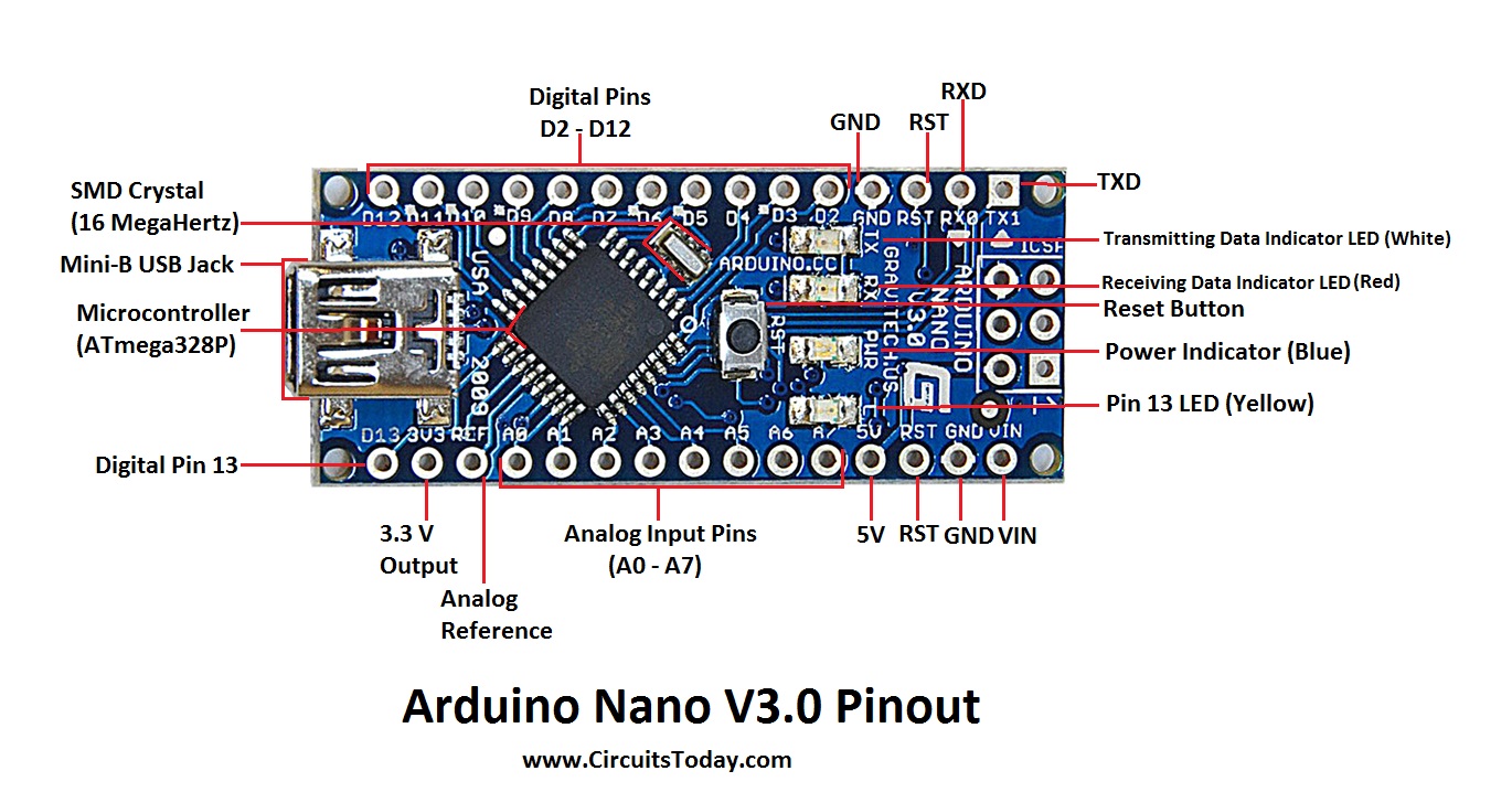 long rampart
should i change pin 4 to pin 13?
 crisp crag
i have a question, ive made a lamp with a 400w battery for portable use but i want to make sure and verify it charges with my feather, does it automatically charge while in use when the battery is connected or is there a part of the code i would need to define in order to have it charge via usb as well as be on ?
north stream
I'm not clear what you're asking. Are you trying to charge a battery with a feather?
crisp crag
i went back to look and found my answer
i was verifying if it indicates if its charging when a battery is connected but its more hot swappable
long rampart
how do i add libraries to my code? i opened the code in the ide and sent it to the arduino but it says the library is missing.
i have it but it's just in a different folder
obtuse spruce
Usually you use the IDE's library manager to install the library - and it puts in the right spot.... If you can find that spot, you can just move your library folder there. OR there is some text preference file that tells the IDE where to look for libraries. If I recall, you need to restart the IDE after editing that file.
long rampart
can you tell me how to define in the ide where to look for libries? or the windows default folder path to that locaiton?
Docs>arduino>libraries?
what is the file extension for a library anyway?
im trying to find the i2c library
i2c_t3.h: No such file or directory
long rampart
is digital 10 on pro mini and nano actually RX? what do MOSI MISO and SS mean? (D12/D11/D10)
vivid rock
@long rampart normally libraries are inside libraries subfolder in your Arduino sketch folder.
Each library is itself a folder, typically containing one or more .h and .cpp files, plus README and library.properties file
as for i2c, normally Arduino uses built-in Wire library for i2c interface: https://www.arduino.cc/en/reference/wire
MOSI, MISO, and SS are common names for signals used by SPI interface, but you can use these pins as regular I/O pins, too
for more info about library structure and manual install, check this guide from adafruit: https://learn.adafruit.com/adafruit-all-about-arduino-libraries-install-use
 vestal sparrow
Hello all, I am using a Circuit Playground Express, and the corresponding library in the IDE. I am curious to understand the difference between the speaker.playSound() vs speaker.say() functions. I am looking here for reference and I am not getting more info there. http://adafruit.github.io/Adafruit_CircuitPlayground/html/class_adafruit___c_play___speaker.html specifically, in the speech examples that come with that library, there are hex PROGMEM arrays and I was wondering if I can do the same for some of the sounds I want to play, and I was not sure how I should generate the sounds. I am looking to use python on my PC to generate this, but I need to know sample rate for that. Can someone point me to how the hex arrays can generated so that i can use speaker.say function? Or is speaker.playSound the recommended way?
elder hare
i hate math 😦 i failed it in school even.... and that was X years ago... xD
i have two ints
Spacing = 2 - 255 (coming from my software)
NumLed = 2 - 72 (on the ESP32 microcontroller)
i need to translate 2 - 255 to 2 - 72 (using floor?)buuuuut... i math know not 😛
 woven mica
elder hare
i hate math 😦 i failed it in school even.... and that was X years ago... xD
i ...
woven mica
elder hare
i hate math 😦 i failed it in school even.... and that was X years ago... xD
i ...
NumLed = map(Spacing, 2, 255, 2, 72);
elder hare
the blue LED on my ESP32 are blinking crazy fast... am i using a pin that i shouldn't use?
cedar mountain
Need more info. The ESP32 itself is just a chip, so it doesn't have a blue LED. It would depend on what board you have and what software you're running.
pine bramble
hey
I have 16 leds wired in my breadboard, I have to multiplex with a shiftregister and make patterns with the leds
im failing
can anyone help
all of the leds goes on
@fresh pendant is there a chance someone can help or is it an inactive server if I may ask
green heath
hello, I am not sure if I am allowed to ask this because its a homework exercise. but I have 4 segment display attached to 2 shift registers. but I cant for the life of me figure out how to read the datasheet and what pins are connected to what.
I have 3 possible ways to read it. the pins on the arduino board, the pins on the microprocessor. and switching those two around in vice versa. my fellow students arent being helpfull
I only need to know SDI, sftclck, and lchclk
and to make matters worse, its sometimes turning on. probably because one of the pins is shorting on the arduino USB port.
 lone ferry
Note that the order of the pins in the schematic isn't necessary the order of the pins on the chip.
green heath
yah I found the part where the teacher said the pinout. (thank god for recorded online lessons). but it just aint working. my code for writing the bits works fine in console :/
elder hare
anyone here using PlatformIO in Visual Studio?... got a question, when i set monitor_flags = --raw inside the platformio.ini and start the monitor and try to upload to my ESP32 VS stops responding and ask if i wanna reopen or close VS....
 finite prairie
Hello,
I'm trying to identify an unknow IC
Anybody to help me pls ?
cedar mountain
That's an SOIC-8 package, I think, but there are gazillions of chips out there with the same form factor. I can't make out any markings in the photo, so unless you have more info, you're probably out of luck, I'm afraid.
finite prairie
@cedar mountain How can I get info?
cedar mountain
Research the board it's used on, for instance. Contact the manufacturer. If you have one in hand, see if the chip markings are visible at a different lighting angle. Measure voltages and signals on the pins while it's running. Examine the surrounding traces to see what kind of circuit it's likely a part of.
Basically figure out how much you need to find this out, or if it's just idle curiosity, heh heh.
finite prairie
@cedar mountain I have board and the only reference on it are NULL on google
Nothink marked on it
cedar mountain
Sounds like a reverse-engineering task, then, I'm afraid.
finite prairie
@cedar mountain any docs to go through ?
stuck coral
I would take some educated guesses first, what does it have, what is it not? What could it be doing?
 stuck coral
You can see a decoupling cap, so once you narrow down the search by pinout
finite prairie
 stuck coral
Is there any other chip on the board?
finite prairie
only resistor and 2 2TY
stuck coral
Nothing on the other side but LEDs correct? And does it do anything over USB or is it only power?
Im going to guess only power

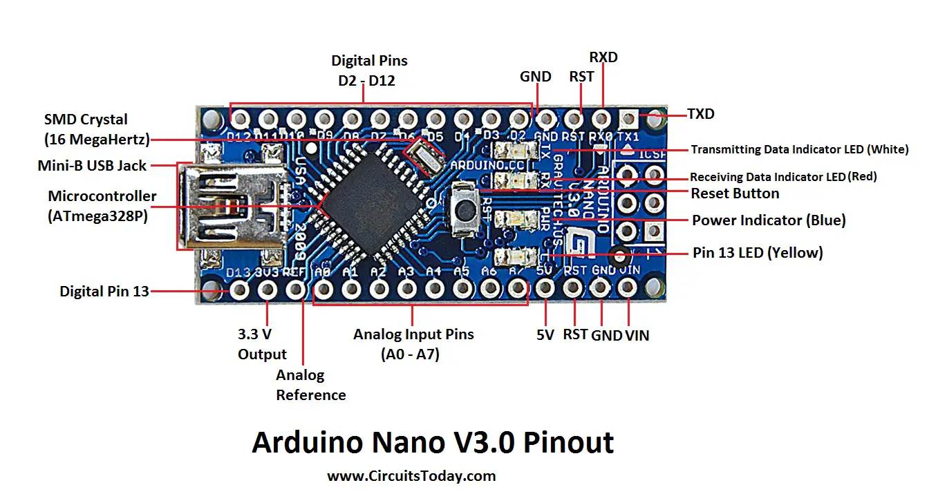


 stuck coral
Looks like one of those no brand cheap as chips micro. An example is the padauk brand, these are hard to ID because they many times have no markings, use non standard programmers/interfaces, and usually a custom CPU
And you can only program one once, you are better off just redesigning a board to do what you want
They cost like $0.03-$0.10 each, and youll find them in everything like kids toys
Usually they dont even have a real c compiler
More on the topic https://www.youtube.com/watch?v=VYhAGnsnO7w

Taking a look at a sub 3 cent microcontroller, and other obscure Chinese manufactures, how to find them, and were to get them in stock.
http://www.padauk.com.tw
https://lcsc.com
Forum: http://www.eevblog.com/forum/blog/eevblog-1132-the-3-cent-microcontroller!/
EEVblog Main Web Site: http://www.eevblog.com
The 2nd EEVblog Channel: http://www.y...
finite prairie
thx for info
pulsar junco
So they have no EEPROM?
stuck coral
Nope, only a PROM
stuck coral
No, they are just cheap
pulsar junco
So do you just burn thru a chip every time you want to test code?
stuck coral
Sometimes there is an emulator, and yep, but i mean, you can go through 33 before you hit $1
And its not like youre controlling a robot or have a network stack
pulsar junco
very cool
stuck coral
They are great for blinkies, how many revs of a blinky can you really have?
pulsar junco
I'm ashamed to answer that question
stuck coral
Lol, less than $10 worth of $0.03 micros?
pulsar junco
probably a sandwich in 2003 prices worth
pulsar junco
whats 3 between friends
stuck coral
Dang it
long rampart
i tried to connect HC-05 to arduino nano but the IDE wont send commands. i opened serial monitor on same COM as the arduino thats hooked to the HC-05 but i get no response to any command i know of
the BTLE module is blinking but i cant connect this or any other way
wiring:
(arduino>HC-05)
GND>GND 5V > 5V
3V3>EN TX1>RX RX0>TX
 alpine oasis
Hi. I'm looking for a way to measure air quality in the working room. MQ 135 seems too inaccurate and ineffective. MH-Z19 seems maybe too expensive. But what about CJMCU-811 CCS811? I can't find comparisons. Can somebody help me with it?
 fresh hemlock
I want to power 2 sg90 servos, can I do this with a 4 pack of AA batteries?
vivid rock
possibly, but in general alkaline batteries are rather poor choice : they cant provide high current, and even a micro servo can require over 1A when stalled
LiPo batteries are much preferred, but would require voltage converter to go from 2-cell lipo (7.4v nominal) to 6v for the servo
fresh hemlock
so as temporary solution for running 2 sg90 servos would it damage them or my boared if i use the 4 x AA recharble battery?
vivid rock
no, it won't damage anything
worst thing that happens is that when servos try to draw too much current, voltage drops and your board will reboot
rechargable are actually much better than alkaline
fresh hemlock
ok thanks Ill give it a go
 twilit hare
hey all, quick question: I'm playing around with an ESP32, than uses a number of buttons to wake-up the device. In order to wake multiple buttons from deep sleep, you have to set the interrupts to HIGH. This works for all of the buttons; however, I also want to use an RTC to wake the device... but the RTC Interrupt causes a LOW signal. Any tricks to adding a second device to "flip" a low to HIGH? I'm using an MCP23017 right now... which seems like overkill. I'm also considering a TPL5111 (in one shot mode), or (ugh) a 555. Any thoughts/tips would be greatly appreciated!
twilit hare
@candid topaz Yeah - I was just reading about those... that's the simplest way to go.. I didn't know exactly to term to look for
 candid topaz
or maybe... pnp transisor? but i am not sure
stuck coral
@twilit hare why dont you set the inturrupt as FALLING?
Then you just trigger the IRQ when the line goes low
Apologies, for the ESP32 you need to use esp_sleep_enable_ext0_wakeup to setup the IRQ for deep sleep, but you can still set the IRQ to trigger on a low signal
twilit hare
@stuck coral Exactly - except that I'm using multiple pins for wake up (the RTC or a button press) - so I have to use EXT1 - which is wake when ALL PINS are LOW or when ANY PIN is HIGH. So, I have to flip the RTC IRQ
stuck coral
I thought you could use EXT0 and EXT1 at the same time, then you just need a IRQ handler that will handle this condidtion
twilit hare
and I can't use EXT0 and EXT1 and the same time
stuck coral
Why not?
twilit hare
well... it's a little more complicated - I'm waking with multiple sources, including the touch pads - and (based on my research and testing), EXT0 conflicts with TouchPad wakeup
stuck coral
Not according to what Im reading
twilit hare
but, maybe that's not the case... I'll try to enable EXT1, EXT0, and touch... and if that doesn't work, then I'll grab an inverter
stuck coral
void print_wakeup_reason(){
  esp_sleep_wakeup_cause_t wakeup_reason;

  wakeup_reason = esp_sleep_get_wakeup_cause();

  switch(wakeup_reason)
  {
    case ESP_SLEEP_WAKEUP_EXT0 : Serial.println("Wakeup caused by external signal using RTC_IO"); break;
    case ESP_SLEEP_WAKEUP_EXT1 : Serial.println("Wakeup caused by external signal using RTC_CNTL"); break;
    case ESP_SLEEP_WAKEUP_TIMER : Serial.println("Wakeup caused by timer"); break;
    case ESP_SLEEP_WAKEUP_TOUCHPAD : Serial.println("Wakeup caused by touchpad"); break;
    case ESP_SLEEP_WAKEUP_ULP : Serial.println("Wakeup caused by ULP program"); break;
    default : Serial.printf("Wakeup was not caused by deep sleep: %d\n",wakeup_reason); break;
  }
}
This is an example IRQ handler ^
twilit hare
yes, that what I was trying.....
but I think there is a conflict. I found one in my initial testing, and was confirmed in this write up:
Note that using internal pullups/pulldowns also requires RTC peripherals to be turned on: this makes “esp_sleep_enable_touchpad_wakeup()” to NOT work! (docs.espressif.com/projects/esp-idf/en/latest/api-reference/system/sleep_modes.html#_CPPv332esp_sleep_enable_touchpad_wakeupv), throwing an exception: “E (151) sleep: Conflicting wake-up trigger: ext0”
stuck coral
@twilit hare Im not reading that it wont work, just that it wont work with pullups/downs, and the guy is also wrong in other points, so not sure how credible that info source is
Im not seeing the note he quotes anywhere on the interwebs
Also, if it conflicts, how so?
Even on the page he links... not seeing it
I would like a technical explaination
twilit hare
@stuck coral fair enough. I'll try EXT0, 1, and Touchpad again, and will let you know what I find. I'll also try w/o pullups
stuck coral
Sounds good, I went through the touch sensor application note, programming manual, and general documentation and cannot see a note about it
Here is a further note! Finally, so you might be right, and in their IRQ example they dont include a EXT0, you might try a NOT gate or a PNP transistor with a 1K and 10K resistor as mindaugas pointed out
Revisions 0 and 1 of the ESP32 only support this wakeup mode when RTC peripherals are not forced to be powered on (i.e. ESP_PD_DOMAIN_RTC_PERIPH should be set to ESP_PD_OPTION_AUTO).
Still might be able to get around it via turning off pullups/downs, from what Im reading it forces the peripheral to be powered on
pine bramble
Can I chain Stemma QT devices with the first device being hardwired? Specifically: I have a feather M0 board, hardwired I2C data and power, etc to a TofF Sensor that has a QT plug. Can I plug a QT wire from the ToF Sensor to another device (io expander, temprature sensor, etc) and the M0 feather will be able to address both devices as needed?
stuck coral
Yes
pine bramble
AWESOME. I thought so, since the plugs just seems to be the normal 4 wires handy without soldering. Thank you!
twilit hare
@stuck coral To follow-up on the EXT0 and EXT1 wake-up sources (with touchpad) - I wasn't able to get all 3 working at the same time [even when I removed software pullups/pulldowns]. I ended up creating an inverter with a transistor and 2 resistors. Thanks for all your help!
stuck coral
@twilit hare hm, you're welcome, it appears to me there are different revisions of the ESP32 silicon, and the EXT0 is slightly different in some
twilit hare
I'm ultimately going to move to the ESP32s2. I don't need BLE, and I ultimately want to build a product that can be "hacked" with arduino or CircuitPython. So, I'm not going to get too bent out of shape about it right now.
stuck coral
Nice, I agree the ESP32S2 looks pretty good, I like the fact I can ditch the USB-UART IC
 deep salmon
I need to split the power between 3 components. I'm soldering a bunch of wires together atm to make it work, but I want to clean it up. Is there a module/device I can buy? I can't google it for the life of me, know idea what it'd be called.
north stream
For lower power: https://www.adafruit.com/product/874

These are like the fancy electronics equivalent of the wire nuts electricians use to bind wires together. They are a lot easier to use as well! Each block connector has a metal block inside ...
For higher power: https://www.adafruit.com/product/737

Imagine terminal blocks that are cut out of one solid piece of brass, designed to distribute power. Well, that's what we have here! These machined bus bars are for when you want to ...
deep salmon
ty, sir!
 young flint
(using a circuit playground bluefruit)
for some reason, while reading capacitive touch values using the example code (https://learn.adafruit.com/circuit-playground-fruit-drums/hello-capacitive-touch) or in other projects not using bluetooth i get readings between 0-10000~, but using it in projects that use bluefruit only gives me "65534" as an output? i tried integrating it the adv_advanced and the hid_mouse examples and achieved the same results. are bluefruit and reading cap values not compatible?
obtuse spruce
I'd like to start using Visual Code Studio for my Arduino development. Any opinions on using Platform IO vs. Microsoft's Arduino extension?
elder hare
im so used to coding for ESP32 but am trying to make the code also work on ESP8266 but am i missing something here? i see the DNS printout but can't connect to the ESP8266.. i can with the locaIP but not the DNS...
    WiFi.begin("SSID", "PASSWORD");
    while (WiFi.status() != WL_CONNECTED) {
      delay(500);
      debug.LevelInfo("[WIFI]", "[STATUS]", "Connecting to WiFi..");
    }
    debug.LevelSuccess("[WIFI]", "[STATUS]", "Connected");

    Serial.print("IP address: ");   // Quick an dirty serial print
    Serial.println(WiFi.localIP()); // Quick an dirty serial print

    if(!MDNS.begin("testMachine")) {
      debug.LevelWarn("[DNS]", "[SETUP]", "Error starting mDNS");
      return;
    }
    debug.LevelSuccess("[DNS]", "[NAME]", "testMachine");
  }
 haughty mural
obtuse spruce
I'd like to start using Visual Code Studio for my Arduino development. Any opini...
haughty mural
obtuse spruce
I'd like to start using Visual Code Studio for my Arduino development. Any opini...
I had problems with the arduino extension that required me to install older vscode release. Platformio has been rock solid. Not that the two require different directory structures.
pine bramble
Heya! 🙂
pine bramble
Could anyone help me figure out why this wouldn't be seeing pin changes on digital pins 5-8 on a sparkfun pro micro 5v 16mhz using an attachInterrupt call?
#include <ArduinoJson.h>
const int RXLED = 17;
const int LOOP_SLEEP = 500;
const int digitalPins[4] = {5, 6, 7, 8};
volatile bool sendData;
volatile int lastSendData;
volatile int previousState[4];
volatile int currentState[4];
volatile unsigned long previousStateTime[4] = {0,0,0,0};
volatile unsigned long currentStateTime[4] = {0,0,0,0};


void isrDigitalPinChange() {
  unsigned long changeTime = millis();
  sendData = true;
  char[30] portdump;

  sprintf(&portdump, "A: %#lx\n", PORTA);
  Serial.println(portdump);
  Serial1.println(portdump);

  sprintf(&portdump, "B: %#lx\n", PORTB);
  Serial.println(portdump);
  Serial1.println(portdump);

  sprintf(&portdump, "C: %#lx\n", PORTC);
  Serial.println(portdump);
  Serial1.println(portdump);

  sprintf(&portdump, "D: %#lx\n", PORTD);
  Serial.println(portdump);
  Serial1.println(portdump);

  for (int i=0; i<4; i++) {
    int newState = digitalRead(digitalPins[i]);
    if (newState != currentState[i]) {
      previousState[i] = currentState[i];
      previousStateTime[i] = currentStateTime[i];
      currentStateTime[i] = changeTime;
      currentState[i] = newState;
    }
  }
}


void setup() {
  Serial.begin(9600);
  Serial1.begin(115200);
  sendData = true;
  for (int i=0; i<4; i++) {
    pinMode(digitalPins[i], INPUT);
    attachInterrupt(digitalPins[i], isrDigitalPinChange, CHANGE);
  }
}

void loop() {
  if (sendData) {
    const int CAPACITY = JSON_OBJECT_SIZE(4);
    StaticJsonDocument<CAPACITY> doc;
    for (int i=0; i<4; i++) {
      JsonObject obj = doc.createNestedObject();
      obj["v"] = currentState[i] ? 1 : 0;
      obj["t"] = currentStateTime[i];
    }
    if (Serial.availableForWrite() > 0) serializeJson(doc, Serial);
    if (Serial1.availableForWrite() > 0) serializeJson(doc, Serial1);
    sendData = false;
  }
}
Code is easier to read if it is bracketed with markup, at the beginning and end of the code.
To do so, three backticks are used, and the name of the language after them (but only at the top):
```cpp
my_function();
```
back quiet
cedar mountain
@pine bramble The portdump code looks a little weird to me. Normally I'd expect to see char portdump[30] instead of char[30] portdump, and you'd pass portdump to sprintf() instead of &portdump. It might be crashing the first time the interrupt is called.
 stable forge
@young flint is this with CircuitPython? If so, ask again in #help-with-circuitpython, and could you give the minimal example that shows the issue?
obtuse spruce
@pine bramble - I think your portdump is fine if uncommon style... but I don't think it is okay to write to Serial ports from an ISR. Also PORTA etc... don't seem to be defined anywhere.
volatile on your global variables probably isn't doing what you think it's doing.... you don't really need it.
shrewd wyvern
obtuse spruce
<@456226577798135808> - I think your `portdump` is fine if uncommon style... but...
I am using Plataform IO... but can't really compare to the Microsoft extension I never tried it
obtuse spruce
Does platformIO get the latest core from Adafruit? someone once said that the cores lagged.... not sure why they would
shrewd wyvern
hm what library is that?
I have used the Adafruit Unified Sensor lubrary... at Platform IO they have version 1.1.4
obtuse spruce
the core is the board library - like Adafruit SAMD stuff - including the Arduino core libraries for that board
stuck coral
There does tend to be a little lag with PlatformIO, its just the Arduino IDE is lacking in so many ide features, even vim can do better, I prefer the slightly older packages for autocomplete and the ability to Ctrl-Click functions 😆
 blazing crane
I have a limit switch here wired like this
And my code looks like this
In theory, it should print "change" each time I press or release the switch
Instead, it prints "change" like 4-8 times when I push it, and once when I release it
obtuse spruce
welcome to debouncing!
When a switch makes contact, there is physical jitter - and it quickly makes and breaks contact a few times as it depresses.
It does the same on release.
though perhaps, not as much in your case.
blazing crane
So, I followed this here https://youtu.be/6wuInF9Yw08, and I noticed they wired it to the open position, and checked if it read low. I only care when something hits the button, not when it is released. If I wired to the closed position, and checked for high, would it have the jittering effect on the release and not affect the pressing?

Wiring Limit Switches Arduino Tutorial
The limit switches are used to detect the physical limits of the working area and to position
More detail for GRBL CNC user
https://github.com/gnea/grbl/wiki/Wiring-Limit-Switches ::::::::::: SUPPORT CHANNEL ::::::::::::::::::::::::::::::::::::::::::::::::::::::::::::::::::::::
Please Donate To Help Me Af...
obtuse spruce
the wiring doesn't affect the jitter - the mechanics of the switch inside, and the force of activating it do ---
It is best to just debounce:
int lastState = HIGH;
int nextState = HIGH;
unsigned long nextValidAt = 0;

void loop() {
    unsigned long now = millis();
    int currState = digitalRead(7);
    if (currState == nextState) {
        if (nextValidAt && now > nextValidAt) {
            Serial.println("Changed!");
            lastState = nextState;
            nextValidAt = 0;
        }
    } else {
        nextState = currState;
        nextValidAt = now + 20;  // wait 20 ms.
    }
}
Now that detatchInturrupt is fixed, that is also an option for debounce that works really well
shrewd wyvern
obtuse spruce
the core is the board library - like Adafruit SAMD stuff - including the Arduino...
Hm for what I could find Atmel SAM core is on 5.0.1 version...
obtuse spruce
right .. but I compile against the Adafruit SAM core... which is like 1.6.2 (clearly different version streams)
stuck coral
shrewd wyvern
Hm for what I could find Atmel SAM core is on 5.0.1 version...
Check when they update the core how long it takes to get to your platformio instance, its also an issue with libraries
Though that is more of an organizational issue
blazing crane
So, should I use detachInterupt or mzero's code?
obtuse spruce
I don't understand how you'd use detachInterrupt to debounce.... but that's me...
blazing crane
I mean, I've done a lot before w/ the coding side of things, just not the hardware side (which is why I came here asking about wiring). Feel free to "confuse me" lol
stuck coral
obtuse spruce
I don't understand how you'd use detachInterrupt to debounce.... but that's me.....
Well you use an ISR to handle the initial trigger, then in that you detatch the IRQ, and in the loop you have a timeout that re attatches it. You couldnt do that before
obtuse spruce
Note: that implements debounce of "n ms. after first transition" -- whereas my code implements "n ms. of stable" -- slight difference... I think unless you need the interrupt for some other reason... I'd stick without it.
stuck coral
Well you can implement it that way too @obtuse spruce
Just using an IRQ vs not, you couldnt do it before, now you can and its pretty neat
blazing crane
So, in the code you sent, the variable lastState does nothing. What's it there for?
obtuse spruce
Ah - I assumed your code was "stripped down" and that you'd need the state of the switch later on...
so - yeah - it's doing nothing
blazing crane
I do plan on adding to the code, this was a first test w/ just the switch
To be fair though, this project is gonna have many nanos in it, and this is one of the least useful of them. There's a little more that needs to be added, but not a ton
obtuse spruce
if you - or anyone - plans on having more than one swtich - you can use this simple DebouncedSwitch class I wrote: https://gist.github.com/mzero/c5165429aa14413271dfe667ead0a6e6
pine bramble
Thanks for the ideas to check out
i think you're right about the declaration of the portdump thing. I was throwing that together quickly last night to try to debug
normally would look like this:
#include <ArduinoJson.h>
const int RXLED = 17;
const int LOOP_SLEEP = 500;
const int digitalPins[4] = {5, 6, 7, 8};
volatile bool sendData;
volatile int lastSendData;
volatile int previousState[4];
volatile int currentState[4];
volatile unsigned long previousStateTime[4] = {0,0,0,0};
volatile unsigned long currentStateTime[4] = {0,0,0,0};

void isrDigitalPinChange() {
  unsigned long changeTime = millis();
  sendData = true;
    for (int i=0; i<4; i++) {
    int newState = digitalRead(digitalPins[i]);
    if (newState != currentState[i]) {
      previousState[i] = currentState[i];
      previousStateTime[i] = currentStateTime[i];
      currentStateTime[i] = changeTime;
      currentState[i] = newState;
    }
  }
}

void setup() {
  Serial.begin(9600);
  Serial1.begin(115200);
  sendData = true;
  for (int i=0; i<4; i++) {
    pinMode(digitalPins[i], INPUT);
    attachInterrupt(digitalPins[i], isrDigitalPinChange, CHANGE);
  }
}

void loop() {
  if (sendData) {
    const int CAPACITY = JSON_OBJECT_SIZE(4);
    StaticJsonDocument<CAPACITY> doc;
    for (int i=0; i<4; i++) {
      JsonObject obj = doc.createNestedObject();
      obj["v"] = currentState[i] ? 1 : 0;
      obj["t"] = currentStateTime[i];
    }
    if (Serial.availableForWrite() > 0) serializeJson(doc, Serial);
    if (Serial1.availableForWrite() > 0) serializeJson(doc, Serial1);
    sendData = false;
  }
}
despite visibly seeing the inputs (inline LEDs) to those pins change, I get nothing back. At one point or another this code was on a different pin number and I know the ISRs do fire in some cases. is there more setup I need to do on the IO pins?
actually thats an old photo for the sense of it.. but in this particular case the lights on the left were indeed lit and the micro was actually powered up 🙂
^ MegaMute @pine bramble on Twitter 😉
obtuse spruce
I don't see why that wouldn't fire at all... unless those pins can't be used to interrupt on your board. I do see there is a race condition, and you could miss some transitions.
pine bramble
I'm not super concerned as long as the most current state gets out. The rest is just nicety. Also, in this particular setup, normally you'll only be able to hit a then b then c. and most people are doing this slowly. Most people being me. 🙂
basically its a hardware mute button. once the key, the remote relay and the final blue switch there are closed, the power gets through to the jack relays.
the rest is a micro to inspect the power at the various points.
this photo was while I was cutting the IO lines for those sense points.
it should be really unlikely for the ISR to fire redundantly, but all I really care is that the most current state is emitted out via the bluetooth/serial
it will also send an update pulse every 500ms soon here..
but i think something is funky with the json code.
I was thinking there was a register that indicated which pin triggered the ISR
then i could just check the changed pin
obtuse spruce
Two thoughts: 1) Certainly drop JSON to debug this. Just simple Serial.print. 2) If this is all this sketch is going to do... then perhaps interrupts are just making your problem harder. You can just poll the inputs in loop() - it'll be plenty fast enough for what you describe.
pine bramble
how about energy efficiency?
obtuse spruce
ah - possible better with interrupts - but you might need to do other things to get it into the lower power state?
pine bramble
Hey guys i was wondering if i provided a proper 100mV reference (to arduino uno aka atmega328p) would i be able to measure signal 0 to 20mV with ok accuracy?
north stream
I suspect it wouldn't work well, but it might be worth an experiment
pine bramble
Yeah the datasheet says the reference must be 0.6V minimum
pine bramble
I am looking at maybe running this code instead?
const int RXLED = 17;
const int LOOP_SLEEP = 500;
const int digitalPins[4] = {5, 6, 7, 8};
volatile bool sendData;
volatile int lastSendData;
volatile int previousState[4];
volatile int currentState[4];
volatile unsigned long previousStateTime[4] = {0,0,0,0};
volatile unsigned long currentStateTime[4] = {0,0,0,0};

void isrDigitalPinChange() {
  unsigned long changeTime = millis();
  sendData = true;
    for (int i=0; i<4; i++) {
    int newState = digitalRead(digitalPins[i]);
    if (newState != currentState[i]) {
      previousState[i] = currentState[i];
      previousStateTime[i] = currentStateTime[i];
      currentStateTime[i] = changeTime;
      currentState[i] = newState;
    }
  }
}

void setup() {
  Serial.begin(9600);
  Serial1.begin(115200);
  sendData = true;
  for (int i=0; i<4; i++) {
    pinMode(digitalPins[i], INPUT);
    attachInterrupt(digitalPins[i], isrDigitalPinChange, CHANGE);
  }
}

void loop() {
  if (sendData) {
    char stateString[255];
    int strLen = 0;
    stateString[strLen++] = '[';
    for (int i=0; i<4; i++) {
      strLen += sprintf(stateString + strLen, "{\"v\"=%d,\"t\"=%ul}", (currentState[i] ? 1 : 0), currentStateTime[i]);
      if (i<3) stateString[strLen++] = ',';
    }
    stateString[strLen++] = ']';
    stateString[strLen++] = '\0';
    if (Serial.availableForWrite() > 0) Serial.println(stateString);
    if (Serial1.availableForWrite() > 0) Serial1.println(stateString);
    sendData = false;
  }
}
I should just put this on github. it's open source 🙂
For the next presidential debate 🤣
pulsar junco
need a button to tell the other to hush up
pine bramble

GitHub
Contribute to MegaMute/arduinoProMicro5V development by creating an account on GitHub.
it's just an inspection / SCADA style monitoring only of a relay latch lock-out key/remote/master and XLR jacks that are connected/disconnected physically.
Basically an over-engineered mute button 🙂
dreamy minnow
hello guys! i have a bit of a longer question so bear with me please. i have 4 leds from which i digital read off, but i would like to make this scalable to a theoretical infite number. so, whenever a digitaRead on any of these leds happen, i start a timer, and then check if in that time interval, all the other leds have also fired off. i got everything down except figuring out how to check which led turned on first, and then checking all the others, except him
i hope this makes sense
i tried to figure that part by making it stupid, as in, writing a scenario for every single pin. if digitalread pin 1 == high, then start timer, and check for pin 2,3,4. then the same again, if digitalread pin 2 == high, then start timer, and check for pin 1,3,4 etc
in hopes of figuring how to write a function where i change the variables, but i am very bad at math, and also a novice in coding
if anyone has any ideea, please do ping me as i will most likely be asleep (5 am)
oh i just realised. for other aplications it would be handy to also know when the last led fired, not speciffically for leds, but just in general
 wraith current
@dreamy minnow so the leds are getting turned on/off and you are doing a digital read to see when they are turned on and off ?
dreamy minnow
yes
they will fire mostly simultaneously, but not in perfect sync, and i want to account for that by giving them some ms for tolerance
basically i want to see if they all fire at the "same time". and give some tolerance for that "same time"
but, if i do this "smartly". i can increase the number of leds, and that tolerance, to whatever i want, for future projects, and adding the last thing i mentioned, where i can also check when the last led fired, would also greatly increase the "handyness" of this program
i do have a vague ideea on how to this, but i have to learn about matrixes first, i think?, and i will do that tommorow
but, as it has been proven on multiple ocasions, the people here have opened my eyes quite a lot about how to think about a problem, so i thought i should also seek some advice on different solutions
obtuse spruce
@dreamy minnow Let me see if I can restate the problem: You have several pins that you'd like to digitalRead() from. (That they are driven by LEDs that something else is turning on and off is not relevant, right? - These are just digital inputs.) And you want to monitor them, and do something if all of them turn on within some interval.
Now - we need to define "all on" - From your description, I gather that they don't all need to be on at the same time, but only that they have "flashed" on within some time interval.
This is an easy problem, but not approached as you have with a timer. Instead, the key is understanding the condition to be checked, and maintaining the data necessary to test it. Let me code up a quick sketch....
dreamy minnow
Hi! thanks for responding, i left my phone on in case someone replied again, so i could clarify things. I did fall asleep and i am a bit woozy, so i'm sorry in advance if i won't be as clear as i should. i will of course check every message again tommorow with a clear head.
obtuse spruce
Okay
#include <Arduino.h>


const int numInputs = 6;
const int inputPins[numInputs] = { 5, 4, 3, 9, 11, 2 };
  // whatever input pins you need to check

const unsigned long onWindowWidth = 100; // in milliseconds
bool seenOn[numInputs];
unsigned long onTimes[numInputs];

void clearInputs() {
  for (int i = 0; i < numInputs; ++i)
    seenOn[i] = false;
}

void updateInputs(unsigned long now) {
  for (int i = 0; i < numInputs; ++i) {
    if (digitalRead(inputPins[i] == HIGH)) {
      seenOn[i] = true;
      onTimes[i] = now;
    }
  }
}

bool allInputsOn(unsigned long now) {
  unsigned long windowStart = now - onWindowWidth;

  for (int i = 0; i < numInputs; ++i)
    if (!seenOn[i] ||  onTimes[i] <= windowStart)
      return false;

  return true;
}

void setup()
{
  for (int i = 0; i < numInputs; ++i)
    pinMode(inputPins[i], INPUT);

  clearInputs();
}

void loop()
{
  unsigned long now = millis();

  updateInputs(now);
  if (allInputsOn(now)) {
    clearInputs();

    // do what you want when all were seen on
  }
}
A little long, but I broke up things into small functions so each part would be clear and stand on it's own. The idea is to NOT set timers, instead, we ask at any given moment, how do we know if "all the leds went on?" The answer is "if, in the last n milliseconds, we saw each light go on... then we can say that they were all on together, close enough." That is exactly the function allInputsOn -- see if that function makes sense first
The the rest is just making sure that that function has all the knowledge it needs at any given moment. clearInputs is used to forget that we've seen any lights on. updateInputs simply says - "if the light is on, then we've seen it, and most recently we've seen it on now".
dreamy minnow
in allInputsOn, as long as it still checking everything, it returns false?