#help-with-arduino
1 messages · Page 81 of 1
 mortal ferry
Gotcha, makes sense
 vivid rock
but if you do decide to hand edit these files, make a backup first!
mortal ferry
No, this was never for me, just trying to figure out what options I could give users of this library. Turns out, not so many
They'll have to manually go in and edit these files if they want to change how the RMT behaves. But if you're actually advanced enough with your project to worry about RMT channels like that, maybe it's not a big deal.
 thin grove
Really new to arduino and ive been getting started with familarizing myself with c
so today i make my first efforts but it has trouble compiling
 north atlas
Can someone please help me? I am a noob and am setting up this laser but for whatever reasons its not working
Im using the exact config from https://create.arduino.cc/projecthub/infoelectorials/project-007-arduino-ky-008-laser-module-project-a62c94
I have gotten a few things to work like turning on a motor and the blink sketch. I have tried different wires and lasers as well

Arduino Project Hub
The perfect project for any beginner featuring a simple-to-program but powerful laser module, an Arduino board and basic coding functions. By Electorials Electronics.
vivid rock
what exact lasers have you tried? can you upload photos of the laser modules (ideally with a link to their primary website or documentation if available).?
north atlas
they are all ky-008 I just tried different ones from the pack. I got them on amazon here: https://www.amazon.com/gp/product/B01CG52K1S/ref=ppx_yo_dt_b_asin_title_o05_s01?ie=UTF8&psc=1
 pine bramble
@mortal ferry I think your project can have its own private 'libraries' folder, where you copy the canonical lib into, then modify it there.
#include <Arduino.h>
Put that at the top of every .cpp file and make the .ino file empty (or just comments, no code).
A single directory named src if found will be traversed, for each project.
(For that particular project, I did populate the .ino file because it was the modifcation of someone else's work)
 formal python
hello, how do i ask the arduino to repeat a command several times?
 north stream
I'll normally use a for loop: ```arduino
int count;
for (count = 0; count < 6; ++count) {
// do something
}
my original line is :
void ret(){
if (gcc.dup) {gcc.a =1; gcc.b=1; gcc.l=1; gcc.r=1;}
}
int count;
for (count = 0; count < 6; ++count) {
// if (gcc.dup) {gcc.a =1; gcc.b=1; gcc.l=1; gcc.r=1;}
}
right ?
vivid rock
@north atlas first thing I would check: does the laser work if you just connect pin 1 (labeled "S") to 5v and pin 3 to GND?
formal python
@north stream
pine bramble
@mortal ferry I tested it .. only the 'sketchbook' directory is honored. I was under the mistaken impression that 'libraries' could exist as a directory in an individual sketch. Nope. ;)
This is what happened when I made a copy of a well-known library, stripped it of excess stuff, and renamed it (also removing the original, and making an exact copy of the stripped version):
Multiple libraries were found for "FastLED.h"
 Used: /some/path/to/Arduino/libraries/FastLED-Kuvale
 Not used: /some/path/to/Arduino/libraries/FastLED-stripped
Using library FastLED-Kuvale at version 3.3.3 in folder: /some/path/to/Arduino/libraries/FastLED-Kuvale
So it simply uses one of them (don't know why it chose the one it did) and ignores the second one entirely, other than to report its existence.
/some/path/to/Arduino is my "Sketchbook" location.
(The default in Linux is /home/mylogin/Arduino).
north stream
@formal python I'm not sure what gcc.dup is so do you mean check that several times, or if the check passes, do the other assignments several times, or what? Note that // means a comment, so that code won't do anything.
thin grove
int LEDs[] = {2, 3, 4, 5};

void setup(){
  for (int i=0; i<4; i++)
  {
    pinMode(LEDs[i], OUTPUT);
  }
}

void loop(){
  delay(300);
  for (int a = 0; a < 16; a++){
  for (int i = 0; i < 4; i++) {
    int bitVal = bitRead(a, i);
      if (bitVal == 1) {
        digitalWrite(LEDs[i], HIGH);
        delay(300);}
      else{
        digitalWrite(LEDs[i], LOW);
        delay(300);}
    }
  }
}
This code (my first actually!) is intended to count from 0 to 15 and display the binary value through digital pins 2-5.
The issue is that it doesn't count correctly. The value it output generally decreases, but it's obviously not working as intended. Some outputs appear for longer, some turn on and off very quickly. I'm sure its an issue with my code.
Here's the entire binary output it displays before repeating, converted to decimal:
1 2 3 1 2 3 4 5 4 6 7 6 4 8 9 10 11 10 8 12 13 14 15 14 12 8
 reef ravine
the bits are being read in the wrong order, try for (int i = 3; i >= 0; i--) { to reverse to MSB > LSB
(you also need to expressly set all the LEDs LOW after each loop of 'a')
Tip: use ctrl+t to autoformat your code (in Arduino IDE)
 round chasm
hello, i have problems running 2 FORs at the same time, it runs 1 and when its done, other FOR then starts
if (ct == cr){
for(int i = 1; i <= r; i++){ // for red light dimming, r means max brightness
  analogWrite(9,i); // mosfet module controlling
  delay(sr);
}
for(int i = 1; i <= gbw; i++){ // for green, blue, white lights dimming, gbw means max brightness
  analogWrite(6,i); // mosfet module controlling
  delay(sgbw);
  }
they should start and end at the same time, but that doesnt happen, how could i fix it?
vivid rock
@round chasm , "computers are stupid: they never do what you want them to do, only what you tell them to do"
your code has two loops, one after the other; the computer does exactly that, runs one loop, and after that, the other
if you want both running at the same time, you need to put both analogWrite commands in the same loop. It would be easy if delays sr, sgbw are the same, or at least multiples of the same common time
or if the number of brightness levels r and gbw are equal
round chasm
The problem is that they are different, for example i want max r to be 150 and gbw 255. Each of them have for example 30mins
So sr would be = 30* 60/r*1000 and that is 12 seconds i think, the sgbw is different
vivid rock
30 minutes? this is a lot.
ok, give me a sec, i will write something
made a typo there, of course rgbw_pin should be different from red_pin
round chasm
Looks like it might work, also what is uint32_t?
vivid rock
unsigned long integer type
cleaned up a little bit
as you can see, it will be updating the values every second
round chasm
having hard time understanding, but i will try to run it now
vivid rock
the loop has delay(1000); so each iteration of the loop takes one second; counter i, therefore, is the number of seconds since the start
so i/period shows what fraction of the period we have completed; it ranges from 0 to 1.
so max_red*i/period will range from 0 to max_red, exactly as you wanted
round chasm
Thank you, looks like it works, but I measured the voltage of my arduino pins and they are different! Even if i set both analogWrite(pin 6 or 9, 150) one shows 0.09 volts and other 2.89volts
Does it mean that my arduino is broken?
Okay, i found out that voltage doesn't matter because the pins are constantly switching on and off
 steep robin
PROBLEM SOLVED, DON'T HURT YOURSELF TRYING TO SOLVE!
Hey everyone, I'm trying to get an ATTINY84 talking to DS1307 using the tinyrtclib. Does anyone have experience with this? I am able to get my Uno to set the time and get the time out of the RTC when I jumper it into the circuit, but I can't seem to get the tiny84 to interface correctly.
Pastebin
Pastebin.com is the number one paste tool since 2002. Pastebin is a website where you can store text online for a set period of time.
Here is my code. I want to pull the time from the RTC and then shift it out to a 4 digit seven segment via two shift registers. If I take out the RTC calls (lines 57 - 60) then the seven segments will display 1234, so I know that the number processing and shift out is working fine.
Also, lines 62 - 67 are useless right now and will be fleshed out later, so please ignore that section.
When the code is flashed to the micro as written in the pastebin, the seven segments will display 000, which is what I would expect when the RTC is initialized with rtc.adjust(DateTime(2020, 10, 29, 0, 0, 0));, but it never advances beyond that.
I'm using PA4 for SCL and PA6 for SDA on the tiny84
I don't have a schematic drawn up, but I am pretty confident that it is wired correctly. I can make a schematic in KiCad if needed.
Also I have noticed that if I use this to initialize the RTC: rtc.adjust(DateTime(2020, 10, 29, 12, 34, 0)); the seven segments will display 2200 and not advance beyond that. I don't know if that's helpful information
And like I said, if I pull the wires that connect the RTC to the tiny84 and patch my Uno up to the RTC, I can use the RTClib to write to and read from the DS1307 on the same circuit the tiny84 is in.
So I2C pullups are good, XTAL is good, etc. I really think I'm missing something having to do with TinyWireM or tinyRTClib
steep robin
Ok well, I may have figured it out. The ISP pins are shared with the I2C pins and when the programmer is plugged into them it must cause some interference because I just tried the circuit without the programmer plugged in and it seems to work!
 mint palm
Hi, I've received my adabox016 last week but I think I need some help 🙂 Which board should I use on platformio.ini ? (adafruit_feather_m4 seems to match the matrix portal specifications). And other question, to use the wifi, which arduino lib can I use ? I would like to not use circuit python if it's possible, and all projects I've seen in https://learn.adafruit.com/adabox016 seem to use circuitpython instead of arduino.
pine bramble
@mint palm Check the MCU chip and the schematic pinouts.
There won't be direct support for platformio, I'd think.
For regular Arduino IDE the pinmuxing/mapping is basically encoded into the variant.cpp file for the board.
grep boards.txt to find out which boards use which MCU's. Adafruit doesn't use a lot of variants in a given chip part.
ATSAMD21G18A ATSAMD21E18A were the first two SAMD21's they used.
They use a different MCU for the Grand Central (it's got loads of pins).
mint palm
ok thanks @pine bramble I've just find https://learn.adafruit.com/adafruit-matrixportal-m4/arduino-libraries which seems to be what I was lookink for.
pine bramble
ATSAMD51J19A Metro M4/airlift, Feather M4, pybadge M4, pygamer M4, hallowing M4, MatrixPortal M4
ATSAMD51J20A PyPortal M4, PyPortal M4 Titano, PyGamer Advance M4, PyBadge Airlift M4
ATSAMD51P20A GrandCentral M4
ATSAMD51G19A ItsyBitsyM4, Trellis M4, Monster M4sk
That's all out of boards.txt
Feather M4 example:
https://github.com/adafruit/ArduinoCore-samd/blob/master/boards.txt#L781
@mint palm Last time I used PlatformIO (quite a while ago) nobody at Adafruit was keeping them updated; so it was done outside (independently).
They were 3-5 months behind the new stuff, more or less, if I remember at all correctly. ;)
If you're on the same chip the clock will be the same.
But as you can see, the same chip was used on several boards and the pinouts won't match exactly.
 noble obsidian
Following the directions in https://learn.adafruit.com/adafruit-hallowing-m4/building-eyes-from-source-code now - but stuck just getting the Blink example
I get as far as
Sketch uses 10388 bytes (3%) of program storage space. Maximum is 262144 bytes.
PORTS {COM4, COM7, } / {COM4, COM7, } => {}
(Device manager does report I have a COM4, and I tried this both from after double reset ( to boot loader ), and single reset )
(The board used to have a working M0 eyes demo in it)

Adafruit Learning System
MORE of everything that makes this the spoooookiest dev board!
pine bramble
@noble obsidian The Blink sketch toggles GPIO pin D13, once it is set to OUTPUT mode (Push-Pull).
noble obsidian
f
@noble obsidian The Blink sketch toggles GPIO pin D13, once it is set to OUTPUT mode (Push-Pull).
@pine bramble - I think I'm hung up on the sending firmware to the device phase
noble obsidian
maybe there's some magic sequence I missed - any clues on getting the first arduino app installed in a device that had circuit python and other firmware loaded before hand - ( I see on this latest attempt that the eyes app is still blinking - maybe that's a clue )
pine bramble
Well the bootloader is permanent.
So if you double click on the reset button on that module, what blink pattern does it show?

 noble obsidian
double clicked - now I see COM9 in device manager ( the ide reports errors trying to talk to COM7, and a green LED need the 4 sensor pins is solid )
pine bramble
I can't parse that into English. ;) lol
But you kind of painted like a Picasso, a general imagery of what's going on. ;)
They should really have a help with bootloader channel as there's so much traffic on that one question. ;)
noble obsidian
I disconnected the external battery ( getting the flickering yellow led - that they warn about - ignoring it )
red LED pulsing
green LED solid
pine bramble
The red heartbeat is probably bootloader mode.
Sounds like it's not broken.
It means it'll accept an uploaded sketch.
(a 'sketch' is arduino-speak for compiled firmware - an 'application')
noble obsidian
I'm not sure why the error messages ( verbose set ) - is reporting both COM7 and COM9 - while device manager only reports COM9 - (( I'm assuming that COM9 is the Hallowing M0 in boot mode ))
pine bramble
I think the COM number is fungible and is assigned on the fly.
I'm not a Windows user at all. I run Linux here.
noble obsidian
I did one arduino sketch on another computer a few years ago - different hardware - didn't see this problem -
This is the first arduino this Windows 10 computer has seen "ever"
( I'm not sure I should deviate too much to try WSL - thought I do have cygwin available )
Just trying to follow the build the eye 'sketch' for the M0, very glad they have the blinky sketch to run first.
Their blinky sketch does include digital pin 13 as output ( in response to your earlier message @pine bramble )
pine bramble
You'll get it. Everyone does. Nothing's broken.
thin grove
@reef ravine Ok, nearly there, but now it only illuminates one LED at a time. How do I make it so it doesnt exit the loop before all the LEDs are set HIGH?
noble obsidian
thanks @pine bramble - reading forums too - starting here: https://forums.adafruit.com/viewtopic.php?f=25&t=101855
pine bramble
Blinky sketch validates your setup. It ensures things like: you have a good USB cable, rather than a junky one missing wires in it.
I would try to Upload, and when it starts showing repeat COM messages (in white) only THEN do you double reset and get the red heartbeat
The upload messages itsefl are in red, I think, in the lower half of the Arduino IDE window (which you can resize).
noble obsidian
I see the FAQ https://learn.adafruit.com/adafruit-feather-32u4-basic-proto/feather-help#faq-2
-- will read that after your suggestion @pine bramble
 pine bramble
Sometimes you have to manually select the Port in the IDE.
The 32u4 is old school and isn't M0 or M4 related.
Hollowing is gonna be SAMD 51
noble obsidian
I would try to Upload, and when it starts showing repeat COM messages (in white) only THEN do you double reset and get the red heartbeat
@pine bramble this helped - now my read LED is blinking like the sketch says 1 second on/ on second off!!
thank you!!!
( Now I'll check that FAQ 🙂 )
pine bramble
;)
Told ya. ;)
I don't even know my name anymore but I can write it down if asked.
;)
What probably happened is this:
The Arduino IDE 'captured' on the correct COM port.
It'll probably work, again and again, now.
The next time this happens, it'll feel different, because you've seen the fix and how it works.
Part of you will remember that and won't believe it when it stops working. ;)
The USB jack on that board can do three things, which is why all this is annoying.
It can act like a thumb drive, and you can store stuff on it.
It can also act as a serial port, and you can type stuff into it, or it can type stuff at you, in your text terminal.
The third thing it can do is act like a mouse, or a keyboard.
noble obsidian
@pine bramble - tried again - seem like I will need to do the double click while in the upload phase 🙂
pine bramble
You probably need to WRITE DOWN what port worked.
It may in fact switch over to another port number, from COM5 to COM7 let's say.
noble obsidian
I'll research further if there is a place in the IDE to enter COM9
pine bramble
There is.
Do it ten times in a row. On the tenth time I'm pretty sure you'll be able to teach a class on it. ;)
The main thing is the flashy pattern you see during the upload.
That's the feedback part that your mind will recognize as a 'good upload'.
noble obsidian
in the IDE Tools menu seems to display options for selecting com10 and com7 ( guessing this means that these are the com ports when the app is running )
( after resetting to the boot loader I see that I can select com9 )
Now I can type control-U ( for upload ) and reliably download the blink app - thanks again @pine bramble
( I may be back with questions - or to report success )
pine bramble
Yup.
That's it. It makes the correct port visible only if the board is plugged in.
Then you can select it and it'll stick even if the board is no longer present.
I think under some circumstances it can switch to another port on its own, so you would have to iterate all that again to get it back to where it belongs.
If it's enumerated that board on one port, but hadn't let go of it after unplugging it, it'll probably enumerate it a second time on a higher port number.
Eventually (with disuse) it lets go of the higher enumerated port number, reverting back to the lowest available one.
Pretty much the same scheme as a DHCP server, assigning the lowest numbers it can choose from.
I'm describing (above, and only roughly) what happens in Linux.
It's the same hardware, so something vaguely similar should happen in Windows.
In Linux:
/dev/ttyACM0 is the standard enumeration for the first CDC/ACM device (for me that's usually a SAMD21 or SAMD51 board, M0 and M4, respectively).
If I'm connected to that board in the terminal (as in putty) then putty more or less owns /dev/ttyACM0.
I can still upload to the target and update its firmware.
But when I go to talk to the serial port, to converse with it, it's not available.
So I tell putty to talk to /dev/ttyACM1 instead (the next number up, where it is now enumerated).
Sooner or later I have to use /dev/ttyACM0 again, as ACM1 was dropped ('naturally' rather than suddenly).
In Linux, tab-completion in the shell exposes which one is currently active; I type:
 $ ls /dev/ttyACM[TAB]
```_which becomes_:
```bash
 $ ls /dev/ttyACM0
When I hit the [TAB] key, it'll auto-complete what I should have typed.
And that exposed the correct, current enumeration of the device (the SAMD51 board).
reef ravine
@thin grove i'd put a delay at the end of the "i loop" only, that way it'll write all 4 bits, pause, then move to the next value of a
pine bramble
My intuition was that the OP failed to clear the LED's, and parsing existing output would reveal that. ;)
(some LED's stayed on, so the binary was additive by position)
reef ravine
i thought so too but looking at the OP code each bit is being written to the LEDs for each value, i think the delays everywhere are the main confusion 🙂
pine bramble
Well I didn't want to rewrite it the way I think about it, since that's not answering the question.
I would SLOW IT WAY DOWN with delays and watch it carefully and take notes.
May as well learn what the code already does, as written. ;)
reef ravine
since i was too lazy to dig up some LEDs i used serial 😉
pine bramble
haha I like that.
Plus you get a transcript of what you 'saw'. Not as ephemeral.
I found the Control P keybinding in MS-DOS in .. 1983 or so.
I had use of my Dad's computer (and his printer!) for the week-end.
He had to buy a new brick of fanfold paper, on Monday morning, since I'd 'learned' MS-DOS over the week-end, by printing .. everything. ;)
thin grove
Removing the delays makes the lights turn on and off as fast as the code executes. The lights still don't stay on.
I actually already wrote down exactly what the code does, below is the sequence it outputs. Or, just watch the video I recorded.
1 2 3 1 2 3 4 5 4 6 7 6 4 8 9 10 11 10 8 12 13 14 15 14 12 8
reef ravine
if you add a long-ish delay at the end of the "i for" you'll see what each value of "a" is producing
another good practice is to add Serial.print statements so you can see values as the sketch executes
pine bramble
I would scrap the entire code and rewrite it from scratch, 'also'. ;)
reef ravine
also, do you have resistors in series with the LEDs?
pine bramble
Even if you just retype it by hand, from memory, something will pop out at you that you'd overlooked the first time around.
Factor the code. Break it down as simple as possible in any given step.
C programmers tend to get as compressed as they can manage, which is a fundamental mistake (and a flaw of the language's culture).
It's much better to spell out everything explicitly.
reef ravine
i tend to use myVeryLongVariableName but it looks so noobish 🙂
pine bramble
Yeah my boss was very big on proper names for things; I never did pick up that skill.
 steady moss
Hey guys, I’m having a problem with my music maker
It just keeps saying that I don’t have the right connections when trying to run the example sketch
Anyone else has had this problem?
 odd fjord
@pine bramble I kind of liked early Basic where you got 2 characters...
pine bramble
@odd fjord One of the Forth guys did a Forth where he packs three chars into a 32-bit storage unit, plus an integer that specifies how many 'extra' characters are in the 'real' name of the word.
So it actually decides based on the first three chars, plus the length: JERemy and JERomy can't be distinguished in this system. ;)
But JERry and JERemy are distinct as their lengths aren't identical.
odd fjord
Sounds like something that would seem normal in Forth 😉
pine bramble
I'm still working on getting used to it; I think the hidden lesson was: he didn't expect a large vocabulary to be built with it, so 'stop doing that' (building massive vocabularies with the system) because 'that isn't what this is for' dotcom. ;)
odd fjord
😄
 obtuse spruce
@steady moss - Tell us a little more about what you're working with. Which music maker board are you using? And can you cut-n-paste the error message you are getting?
steady moss
"Couldn't find VS1053, do you have the right pins defined?"
This is the only thing serial has to say...
Did everything according the steps but it just doesn't seem to wanna work
obtuse spruce
hrmmm... is the the Adafruit board version? and you're using the Adafruit library? If you can - place your sketch ina pastebin so we can see
I notice you are talking over just data lines, rather than over serial - which I thought was the normal way to talk to that system
which tutorial are you following - as the Adafruit one I know doesn't have you connect via the data pins.
obtuse spruce
Or - are you using the Sparkfun shield, and just stacking it on the Adruino?
 small prairie
In the TFT example sketch (graphictest) how do I can change the pin assignment for SD CS there is no pin 7 on the feather. I’m using the 2.0” tft
obtuse spruce
there is a "graphictest_featherwing" version of that example, BTW
small prairie
Where is that located?
obtuse spruce
do you have the library loaded in the Arduino IDE?
small prairie
I have the ones the guide told me to upload
obtuse spruce
you should be able to find it in the File > Examples menus - or if not, it is just in the directory next to the graphictest
Which feather are you using?
obtuse spruce
The graphictest_featherwing should just work out of the box
it has appropriate defines for TFT_CS and the other pins for each of the common feather boards
small prairie
I can’t find that sketch
obtuse spruce
can you find the source of the graphictest sketch on your disk? Go up one directory from that, then you should see the other examples
on github you can see them: https://github.com/adafruit/Adafruit_ILI9341/tree/master/examples
obtuse spruce
hrm.... are we talking about the library called Adafruit_ILI9341?
steady moss
Using the normal one
Not featherwing
And I’m using the tutorial on the sparkfun site
obtuse spruce
okay, so this board? https://www.sparkfun.com/products/12660

The SparkFun MP3 Player Shield is an awesome MP3 decoder with the capabilities of storing music files onto a run-of-the-mill microSD card, thus giving you
(sorry, that chip is popular, there are a number of different shields for it)
and you've just soldered on the pin headers and stacked them, right?
small prairie
I’m using a feather proto 32u4 and the 2.0” tft display and wires
Can I write into the sketch #define SD_CS ?
obtuse spruce
@steady moss - Your schematic doesn't have connections for D11 through D13 - because you are not using the SD card reader?
@small prairie - you should see a #define for SD_CS at the top of the sketch - you can just change it
small prairie
The sketch doesn’t have SD_CS
obtuse spruce
Sorry, In that sketch it is TFT_CS
This is the sketch you're looking at, right? https://github.com/adafruit/Adafruit_ILI9341/blob/master/examples/graphicstest/graphicstest.ino
small prairie
That’s not the sketch I have I’m using the graphictest that was inside Adafruit ST7735 and ST7789 library
https://learn.adafruit.com/2-0-inch-320-x-240-color-ips-tft-display?view=all i'm using this guide

Adafruit Learning System
This gorgeous IPS display breakout is the best way to add a small, colorful and bright display to any project!
In my sketch there is a tft_CS
The display has both a CS pin and SD_CS pin
obtuse spruce
The SD_CS pin is for selecting the SD card slot for reading SD cards.
You use the CS pin for selecting the Display
small prairie
I want to display a image from a SD card
obtuse spruce
Then you'll need them both connected, each to different pins on the feather
which is fine
But - first get graphictest to work, which doesn't need the SD card
on lines 51 thorugh 53, you'll see:
  // For the breakout board, you can use any 2 or 3 pins.
  // These pins will also work for the 1.8" TFT shield.
  #define TFT_CS        10
  #define TFT_RST        9 // Or set to -1 and connect to Arduino RESET pin
  #define TFT_DC         8
Set those according to which pins you've connected to the corresponding lines on the TFT
Notice that you don't need to connect the RST pin ot a data pin -you can just connect it to the RST line on the feather, in which case you set it to -1 here
small prairie
I’m trying to get the sketch to work without a SD card and I’m getting the error no directory found for afafruit_SPITFT
Arduino: 1.6.11 (Windows 10), Board: "Adafruit Feather 32u4"
In file included from C:\Users\name\Documents\Arduino\libraries\Adafruit_ST7735_and_ST7789_Library/Adafruit_ST7735.h:4:0,
from C:\Users\name\AppData\Local\Temp\arduino_modified_sketch_179942\graphicstest.ino:34:
C:\Users\name\Documents\Arduino\libraries\Adafruit_ST7735_and_ST7789_Library/Adafruit_ST77xx.h:31:29: fatal error: Adafruit_SPITFT.h: No such file or directory
#include <Adafruit_SPITFT.h>
^
compilation terminated.
 twilit hare
hey, has anyone in this channel used the Sharp Memory Display with Hardware display refresh (setting the EMD pin to High, and sending a Square Wave of 1-60Hz to the EIN pin)? I thought it was working on an older version of the library (but it could have been my imagination). It's definitely not working now. Wondering if I'm just doing something wrong... or if there's something in the library that explicitly assumes that it's using a software display refresh. Thanks!
noble obsidian
Just went through https://learn.adafruit.com/synchronized-eyes-with-two-hallowings - but couldn't find link to source code - (.zip or github repo ) many thanks to @heady sparrow for creating these projects ?
I will click through the synchronized learning guide again - maybe I missed it...
( the reason I think I need to compile from source - is that I have two Hallowings - one M0, one M4 )
Also looking through https://learn.adafruit.com/animated-electronic-eyes/overview


Adafruit Learning System
Ride the express bus to the Uncanny Valley
obtuse spruce
@small prairie - you need to install the library from the Arduino IDE library manager
 heady sparrow
@noble obsidian https://learn.adafruit.com/animated-electronic-eyes/software Big green button downloads source. But…I don’t believe it’s possible to mix-and-match M0 & M4 Hallowings…we took a very different approach with the M4 that’s based on altogether different software.
Adafruit Learning System
Ride the express bus to the Uncanny Valley
noble obsidian
@noble obsidian https://learn.adafruit.com/animated-electronic-eyes/software Big green button downloads source. But…I don’t believe it’s possible to mix-and-match M0 & M4 Hallowing
@heady sparrow - I found the M4 eyes code - and compiled it but thought I needed to see the ‘sync’ logic - will keep looking - maybe I will have 2 independent cyclops this year - happy Halloween!
Adafruit Learning System
Ride the express bus to the Uncanny Valley
noble obsidian
@heady sparrow - looking at the code in https://github.com/adafruit/Uncanny_Eyes.git it appears that it is not target for even two M0 or M4 Hallowings would talk to each other as SYNCPIN and SYNCADDR are not defined for the ADAFRUIT_HALLOWING ( though this was based on simple grep of the sources, not actual testing
in config.h:
#if defined(ADAFRUIT_HALLOWING)
...
72: //#define SYNCPIN A2 // I2C sync if set, GND this pin on receiver
73: //#define SYNCADDR 0x08 // I2C address of receiver

GitHub
Contribute to adafruit/Uncanny_Eyes development by creating an account on GitHub.
noble obsidian
On the other hand M4_Eyes for the M4 Hallowing just assumes 1 eye - e.g. - no sync. https://github.com/adafruit/Adafruit_Learning_System_Guides/tree/master/M4_Eyes ( from https://learn.adafruit.com/adafruit-monster-m4sk-eyes/m-eyes-firmware )
https://learn.adafruit.com/synchronized-eyes-with-two-hallowings show how to wire two HallowWing boards together and provides .UF2 files - multiple reads of https://learn.adafruit.com/animated-electronic-eyes/overview ( but no source code )
GitHub
Programs and scripts to display "inline" in Adafruit Learning System guides - adafruit/Adafruit_Learning_System_Guides

Adafruit Learning System
Ride the express bus to the Uncanny Valley
 tall knoll
I am having problems with my IR remote control decoder. Everything I push the same button it give me a different code.
 cedar mountain
I guess it's not out of the question for a remote to use a rolling code that changes every time. Do you have some info about the remote to know what codes you expect to see?
tall knoll
I don't know it's some windows 7 remote control
 hollow imp
Hello, in 38400 baud, how long does it take to get 1 bit?
9600 baud => 104 microseconds to transmit a bit, but 38400? it's 26 microseconds?
hollow imp
@pine bramble Thank you very much, that confirms my calculation. therefore 26usec.
pine bramble
I don't know (truly) as an oscilloscope would be definitive.
However:
I wrote a simple bit-banging program that output on serial, and it worked fine.
The program could be used as the basis of a functional analysis of what's really going on.
Real telephone line modems use a complex method to transfer data.
But TTL serial seems to use a simple signalling method.
For whatever reasons they chose to use the same constants for both, but what happens electrically isn't the same, as over the phone you're modulating using audio, to transfer the data.
pine bramble
I'll try to find that program. I did see an oscilloscope screenshot the other day; maybe I can find it by that date.
Been meaning to add this to my github as a specific example. ;)
(The hard part would have been to read serial inbound .. I just did outbound reporting in the project ;)
hollow imp
I don't have an oscilloscope I'm interested, please let me know
pine bramble
I found a method to use the real USART and abandoned further dev on that project. ;)
@hollow imp If I get to it soon I'll just @ you here but if I don't a reminder would help.
hollow imp
Okay. Thank you.
pine bramble
;) It was written for Atmel Start for SAMD21 or SAMD51 (don't remember).
So it'll be written in C.
hollow imp
I do not know, ok
I allow myself to ask a question, I have to process serial port data, I made a program with NodeJS to spy. I am receiving data like this:```
<Buffer 00>
<Buffer 30>
<Buffer 00 30>
<Buffer 03 21 c0 05 03 21 c0 06 02 00 00 02 00 01 02 00 0f 03 20 10 09 03 20 11 0d 03 20 11 20 03 10 1b 0d 03 0a 1b 0d 03 0c 1b 0d 03 20 10 19 03 20 11 38 02 ... 5 more bytes>
I'm guessing not to be fast enough in the recovery, would with an arduino I would be able to recover this kind of data:```
<Buffer 00 30>
<Buffer 00 30>
<Buffer 03 21 c0 05>
<Buffer 03 21 c0 06>
<Buffer 02 00 00>
<Buffer 02 00 01>
<Buffer 02 00 0f>
<Buffer 03 20 10 09>
<Buffer 03 20 11 0d>
<Buffer 03 20 11 20>
<Buffer 03 10 1b 0d>
<Buffer 03 0a 1b 0d>
<Buffer 03 0c 1b 0d>
....
I had a discussion on a similar flow of bytes not very long ago, probably here.
Did find a 'shoe horn' into my serial bit banger; looking for the best example of it (or any good one) at the moment.
hollow imp
Maybe it's with me for the discussion. I've been sure about the project for a little while now
pine bramble
Well, I did remember you are French, and something about a 3:8 decoder. ;)
hollow imp
Ah yes, this is the project before. I am on another project
pine bramble
That code is a mess and never did get published.
It shows the structure of simple TTL serial output, to send ASCII characters over bit-banged GPIO.
For example, to send a W:
https://github.com/wa1tnr/bitbanged-serial-a/blob/main/00-bitbang.d/serial_bitbang_example-a.c#L501
formal python
is there a difference between arduino nano and elegoo nano ?
 lone ferry
Probably, although they should be compatible.
formal python
I see
north stream
That data stream looks like it has a count byte, followed by that many data bytes. To receive that, I'd probably implement a state machine. However, if it gets out of synch, it can be tricky to resynchronize.
tall knoll
Every Remote I try has the same problems
steady moss
Anyone got experience with the adafruit music maker?
small prairie
in order to draw bmp from a TFT SD card do i have to call it with bmpdraw(filename, x, y) ?
i'm following this guide https://learn.adafruit.com/2-0-inch-320-x-240-color-ips-tft-display?view=all
Adafruit Learning System
This gorgeous IPS display breakout is the best way to add a small, colorful and bright display to any project!
small prairie
i have graphic test working and display text lines and stuff
so would drawBMP("/purple.bmp", tft, 0, 0);
be valid?
i tried it and it gave the error drawBMP not declared
same error for bmpDraw("/purple.bmp", 0, 0);
one of the example sketchs with the adafruit library throws the error sketch too big when i try to upload to my feather 32u4 any idea to fix this? sketch is BreakoutST7789-320x240 in the adafruit SD image reader library
 leaden walrus
looks like the build is too big for the 32u4:
Sketch uses 31004 bytes (108%) of program storage space. Maximum is 28672 bytes
is the feather 32u4 your only board?
small prairie
my project needs the form factor of the feather
there is no way to make it smaller?
I just need to show the BMP
leaden walrus
no easy way to make the sketch smaller
is there a reason you need the 32u4?
vs. something like a Feather M4?
small prairie
is there any programming difference between the two?
can i still use arduino and C++ to program a M4?
vivid rock
yes, all feather boards can be programmed using arduino ide
and most sketches work without any changes on any of these boards
leaden walrus
^^ yep
hollow imp
A quick question to understand, how many bits is this buffer?```
<Buffer 03 21 c0 05>
32?
 grand basin
Does debouncing work on potentiometers? Or to put that differently, is there a way to avoid potentiometer parameters from 'skipping around' other than giving an abs() command?
my potentiometers are set to 0-127 with a threshold of 2, but the program I'm using it for subtracts double the threshold from my value, so I'm forced to work within a range of 2-125. I figure finding a way around the threshold constraint would solve the problem.
(threshold meaning 'the change won't register until changed by a value of 2, or whatever number I assign)
leaden walrus
thresholding a delta change is a good approach
could also average the pot reading to reduce sample noise
a cap would essentially do that via hardware
grand basin
Thanks for the suggestions. I've heard of adding a capacitor. Would have to buy a whole pack, but it's worth it if it does the trick.
 pulsar junco
They are pretty useful to keep around tbh
grand basin
Definitely. This is my first electronics/coding project ever and I've amassed so many components in the past few months but I'm missing a lot of the basics still 😆
pulsar junco
I've had my eyes on this series of products for a while for all my nonsense https://www.adafruit.com/product/432

For storing small parts (especially SMT/SMD components), these little modular boxes are ideal. They have individual clear pop-open covers so you can keep only the ones you want open - less ...
north stream
I just bought some to keep my surface mount components (somewhat) organized
heady sparrow
@noble obsidian
pulsar junco
@north stream So you're why they are sold out >.<
north stream
I hope not!
noble obsidian
I downloaded uncanny eyes ( both zip and git ) - the I2C code seems to be ifdefed out for hallowing - am I reading it wrong?
heady sparrow
@noble obsidian It's commented out by default (in config.h) since most folks are using the sketch in a single-eye configuration. Enable lines 72 & 73 and it should be OK.
vivid rock
@pulsar junco I use them a lot for my SMDs, too
and some fishing tackle boxes for larger items such as connectors
noble obsidian
@noble obsidian It's commented out by default (in config.h) since most folks are using the sketch in a single-eye configuration. Enable lines 72 & 73 and it should be OK.
@heady sparrow - I’ll give it a try - thanks !!!
vivid rock
@pulsar junco check these: https://www.amazon.com/gp/product/B000LF3E8O
pulsar junco
I have a similar one, but it must be cheaply made because the separators don't fit well :/
vivid rock
yeah, there are plenty of similar ones - these are quite well made and inexpensive ($3.64 on amazon right now)
pulsar junco
After enough battles that one evolves into
vivid rock
plano is a well-respected brand
but i prefer two separate boxes instead of a two-sided one
vivid rock
so that they spill all your components ont he floor?
pulsar junco
They'd leave a note though
vivid rock
which you can then solder to your board in place of the components....
tall knoll
The Remote still has the problems but I got it to work VB.Net But I can't use it as a mouse
formal python
hello, how do i ask the arduino to repeat a command several times?
This is my void :
void ret(){
if (gcc.dup) {gcc.a =1; gcc.b=1; gcc.l=1; gcc.r=1;}
}
tall knoll
Thank you
formal python
@tall knoll you can help me
tall knoll
Ok
formal python
I would like it to repeat this command 100 times in one second
tall knoll
I'm still learning too
I don't know how to repeat the code
I can't get the mouse to world that all
pine bramble
void me_want_Repeating(void) {
    Serial.print("Here I am");
}
void repeat_me(void) {
    for (int i=100; i>0; i--) {
        me_want_Repeating();
    }
    Serial.println("I got repeated 100 times.");
}
Thank you nis
pine bramble
a counted loop
while repeats forever.
To escape a while loop, you satisfy the while ;)
formal python
thanks you nis, I put that after my void ?
pine bramble
You have to program stuff and try it. ;)
pulsar junco
that will finish much faster than 1 second right?
pine bramble
I'm on the side.
formal python
yes but I don't know where put my original void :
"void ret(){
if (gcc.dup) {gcc.a =1; gcc.b=1; gcc.l=1; gcc.r=1;}
}"
void me_want_Repeating(void) {
    Serial.print("Here I am");
}
void repeat_me(void) {
    for (int i=100; i>0; i--) {
        me_want_Repeating();
    }
    Serial.println("I got repeated 100 times.");
}
@pine bramble
obtuse spruce
@formal python - your code is just a function definition. it can set anywhere in the file, before this code. The functionme_want_Repeating just just an exmaple - do you see that? In the loop (for (...) { ... }) you'll want to replace the call to the example function, with a call to yours.
Does that make sense?
 amber sleet
hey is anyone available to help me with something?
Im using an arduino Pro Micro for something super stupid. I just need it to print strings from an array. super easy the code is fine. the issue im running into is that there isnt enough onboard storage to hold the array of strings. Is there some kind of work around for this, maybe reading line by line from a text file on my computer or something?
ik I could probs just use a python script or even java for this but I wanted to see if it was possible with just the arduino
obtuse spruce
are the strings static? as in they dont' change?
can you put your code in a pastebin for us to look at?
how many strings are we talking about, @amber sleet
amber sleet
the strings are static. As for the code, sure but its pretty simple
Like I said, the main issue is just not enough storage haha
obtuse spruce
I'm happy to look at the code and see which avenues might help you
noble obsidian
@noble obsidian It's commented out by default (in config.h) since most folks are using the sketch in a single-eye configuration. Enable lines 72 & 73 and it should be OK.
@heady sparrow thanks again for the encouragement - just sitting down to dig further in https://github.com/adafruit/Uncanny_Eyes.git
Looked at some of the forked projects - this one https://github.com/sielenk/Uncanny_Eyes gave me some insight - using LEFT_EYE and RIGHT_EYE instead of the jumper to determine which was left and right. I'm guessing I would need 2 binaries anyway - (one M0 vs. one M4)
I'm learning more in the process, and am sure it would be faster to get a pair of matching HALLOWINGs (and M0 might be easier )
I'm also learning how things changed between the M0 and M4 - the display 120x120 to 240x240 - and other things too - I do hope to come back to this later...
GitHub
Contribute to adafruit/Uncanny_Eyes development by creating an account on GitHub.

GitHub
Contribute to sielenk/Uncanny_Eyes development by creating an account on GitHub.
amber sleet
Pastebin
Pastebin.com is the number one paste tool since 2002. Pastebin is a website where you can store text online for a set period of time.
@obtuse spruce
obtuse spruce
cool - give me a second
amber sleet
dont judge me for the strings lol
obtuse spruce
Okay
you can make this fit
but you're making a few mistakes.
These strings are fixed - static - won't change.
But you're storing them in volatile storage
NO
you need to change the type
amber sleet
so not an array
sorry been a while since ive done arduino haha
assembly melted my brain
obtuse spruce
we need a) the array to be constant, and b) the things they point to be const
amber sleet
okay so for a) it would just be adding const infront of my array delcaration right?
obtuse spruce
hold on - lemee get you a code example
amber sleet
okay, thanks for being so patient with me haha
obtuse spruce
also - you don't want to use String here - that is a class, and will need to be initialized at run time ... and... welll can't be as "const" as we want it (we want all this to end up in the flash, not RAM)
amber sleet
okay
obtuse spruce
const char * const array[] = { ... };
This should put everything into flash - as it is immutable, both the array itself, and the strings themselves.
except - don't call it array - that's a C++ type... call it critters
later, in your loop
don't assign it to a String - again more copying for no good reason, and more ram and dynamic allocaiton
Instead
const char *name = critters[i];
Keyboard.print(s);
or really, just
Keyboard.print(critters[i]);
no need for the variable at all!
NOW - depending on your compiler... you may need to sprinkly PROGMEM into that initial declaration.... but I, er, don't think modern compilers need that any more?!?!?
amber sleet
after all that im still at 376% of dynamic memory
obtuse spruce
okay, then we haven't gotten it into falsh
you should have almost no dymanic memory here
try
const char * const critters[] PROGMEM = { ... }
amber sleet
306% now
obtuse spruce
okay... we are not getting the strings into FLASH
we need to do that....
const char PROGMEM * const cirtters[] PROGMEM = { ... }
which may not work....
in which case we need to do the awful thing:
obtuse spruce
const char PROGMEM n0[] = "Bulbasaur";
const char PROGMEM n1[] = "Ivysaur";
...
const char * const critters[] PROGMEM = { n0, n1, ... };
oh no
obtuse spruce
Well - if you are using an editor with multi-select (like Sublime or Atom ) - this won't be too hard, just ugly
obtuse spruce
hold on - I'll just do it
amber sleet
you are my savior
obtuse spruce
you can just paste that at the top of the file...
or put it in a file, critters.hpp and #include "critters.hpp" at the top of your sketch in lieu of the declaration
amber sleet
variable 'critters' must be const in order to be put into read-only section by means of 'attribute((progmem))'
im getting this error for the declaration of critters
amber sleet
when it outputs it just spams a bunch of periods
any idea why?
probably gunna have to change how I iterate through array?
obtuse spruce
no, your array iteration is fine
What is Keyboard --- is that "emulate a USB keyboard" thing?
amber sleet
yeah
obtuse spruce
just for tests - comment out the Keyboard lines and add:
Serial.println(critters[i]);
see if they come out on the serial console
then you'll know you've got that part correct
amber sleet
amber sleet
thats what getting output lol
obtuse spruce
okay
right - reading the chars out of PROGMEM... sorry, I'm much more used to SAMD based devices
okay
hold on a sec
are you printing with the one liner I gave you, or printing with a char * variable?
obtuse spruce
no - okay hold on
amber sleet
ahh got it to work
obtuse spruce
did I miss a PROGMEM somewhere?
amber sleet
Pastebin
Pastebin.com is the number one paste tool since 2002. Pastebin is a website where you can store text online for a set period of time.
added a buffer
obtuse spruce
hmmm...
amber sleet
seems to work
obtuse spruce
actually --- in this case .... now that I think about it....
Serial.println(String(critters[i]))
might have worked, too
obtuse spruce
welcome!
amber sleet
I really appreciate it
 crisp crag
Would anybody know where i can do research on how to get the LED on a Momentary switch to show? the code im using for my project is all sorted how ever the LED on the button itself wont turn on
cedar mountain
There shouldn't be any huge trick to it versus a normal LED. Can you point us to the switch datasheet and describe how you have things wired up?
crisp crag
the product i have

These chrome-plated metal buttons are rugged and look real good while doing it! Simply drill a 16mm hole into any material up to 1/2" thick and you can fit these in place, ...
NO1 -> on Pin 13
C1 -> connected to GND
obtuse spruce
The LED is on the + & - inputs
crisp crag
oh?
obtuse spruce
datasheet says it has an internal resistor
crisp crag
so im using a feather if i wanted to connect these up what would i need to do ?
obtuse spruce
Do you want it to light just when the button is pressed, or do you want to control it separately from the MCU?
crisp crag
id just want the light on when theres power going to it
obtuse spruce
You could connect - to GND, and + to a data pin on the FEATHER. And set the pin to HIGH to light the LED... LOW to turn it off. that should work
at 3.3V it will be (acording to the adafruit page) "light up nicely" -- if you want it super bright - that'd take more electronics
Oh - just on all the time?
Then - to GND, + to 5V or 3.3V on the Feather - or whateever you're using as a power supply
What are you using as a power supply?
obtuse spruce
so, yeah, the 3.3V pin from the Feather will do
crisp crag
oke 1 sec im going to send a picture too to make sure 😄
late night crafting
based on the schematics above this would be plus and negative
i do have C1 and NO1 connected so ill need an additional 2 wires to go from - to GND ASWELL and + to the 3.3V on my feather correct?
also i appreciate the late night help @obtuse spruce : ')
obtuse spruce
I think so
and by + I think you are labeling the furthest pin on that side
right?
crisp crag
yeah
crisp crag
furthest pins on the outer most sides
cool
and this will keep it on all the time as long as theres power right?
i dont need to add anything to my code?
crisp crag
oh perfect
ill do this now then
waiting for the iron to heat up and will comment in like a few mins :>
obtuse spruce
you might try testing it with aligator clips first
crisp crag
i unfortunatly dont have any...
crisp crag
@obtuse spruce we have power!!
 charred sun
With apologies for what might seem like a really basic question. We are playing around with the Matrix Portal that we got in adabox 16 and I can't seem to find any documentation that describes how to read the "up" and "down" buttons in the Arduino IDE. Can anybody give me some advice?
 brave meadow
I am new to CircuitPlayground/Arduino/Etc with that said I am trying to upload a sketch ( Basic Blink ) and although everything appears to be connected when I go to upload it seems to disconnect at the last minute. That could be normal but I always end up with errors:
That is the Verbo Compile/Upload error that I was getting. I assume it is on the upload that there is problems but I can't seem to figure out what.
Pastebin
Pastebin.com is the number one paste tool since 2002. Pastebin is a website where you can store text online for a set period of time.
I did install the board ( SAMD ), and have it selected. I also installed the adafruit libraries. So I assume that isn't the problem.
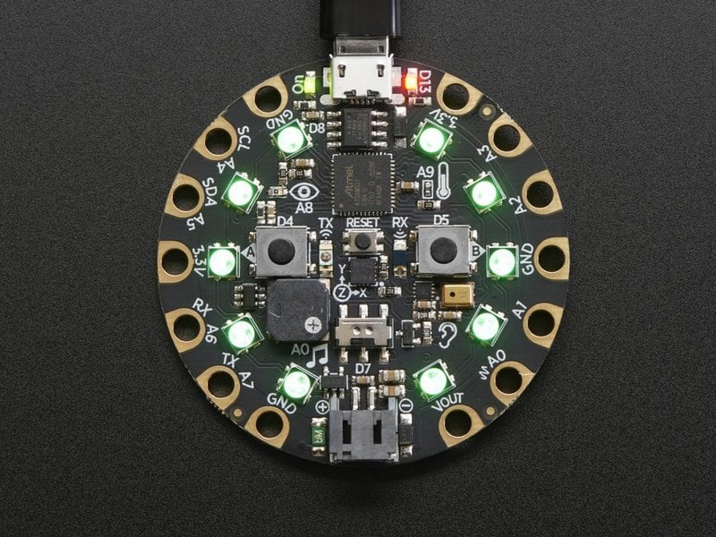
When I plug the board into the PC the NeoPixels light up in a circle, with different colors, when I upload to the board they all turn solid green, however the buttons do not do anything ( which I assume this basic blink is supposed to do )
Adafruit Learning System
Make faster and easier than ever with MakeCode, code.org CSD, CircuitPython or Arduino!
This is how the CircuitPlayground Express shows up in my device Manager. However when I was looking online I have seen other peoples Device Manager show up as Circuit Playground
noble obsidian
I am new to CircuitPlayground/Arduino/Etc with that said I am trying to upload a sketch ( Basic Blink ) and although everything appears to be connected when I go to upload it seems to disconnect at the last minute. That could be normal but I always end up with errors:
...I assume it is on the upload that there is problems but I can't seem to figure out what.
@brave meadow - the pastebin link expired or was deleted - did you get an answer?
brave meadow
Yes I did. I figured it I was trying to load the wrong UF2 files.
I have it working now with Circuit Python
THe problem was I was loading the express and not bluefruit. Didn't think it would cause that kind of problem.
Do you know by chance if the bluefruit can determine gravity direction/down?

Adafruit Learning System
Circuit Playground Bluefruit: Everything amazing about Circuit Playground, now with the power of Bluetooth!
But I can't find it in CircuitPython just acceleration
noble obsidian
wouldn't gravity up down just be a plus/minus sign on the appropriate axis of the accelerometer -
my guess seems to be confirmed on mention of gravity in https://learn.adafruit.com/adafruit-lis3dh-triple-axis-accelerometer-breakout?view=all

Adafruit Learning System
Triple Axis, Tap & Double Tap, & 3 ADCs!
brave meadow
Ya I am playing around with it at the moment printing x,y,z and seeing how it comes out as I turn it etc
 jaunty maple
Hi I'm just starting with electronics and I'm having some minor issues with a 4s 18650 bms board that seems to be shutting off the circuit because its detecting a bypass capacitor as a short circuit. Does anyone have a sec to jump on vc and help me fix it? Thanks in advance for anyone willing to help me out.
For context right now I have it plugged into a buck converter set to 5v with no load. it has worked in this arrangement before but now that they are soldered together they do not. I have checked continuety and there is no continuety between +ve and - ve and my soldered connections are fine.
jaunty maple

eBay
Working current: 15A (Natural cooling 10A, add heat sink 15A, the maximum instantaneous current 30A). Module: 3S Li-ion Lithium Battery Protection Board. Short circuit protection. Size: 50 22 4mm (L W H).
this is the bms
 raven wing
Hey all. Preface: I'm incredibly new to this.
I have a QT PY and a single-cell LiPo. Can I just connect the LiPo to a USB C male and use that as power?
What a cutie pie! Or is it... a QT Py? This diminutive dev board comes with our favorite lil chip, the SAMD21 (as made famous in our GEMMA M0 and Trinket M0 boards).For a limited time: only ...
 gilded swift
Uhhh
Not quite
You can technically put a LiPo on the 5V pin of the Qt Py but it isn’t really a great idea long term
gilded swift
No, the voltage will be regulated but you can’t have the battery plugged in while usb power is plugged in
Oak Dev Tech
We love the Adafruit Qt Py. It really is a cutie! And we love it so much we wanted to help you take the board and your projects on the go!
This little backpack not only brings LiPo Battery power to your Qt Py, but also battery charging so you can easily recharge your project.
I’m making one, but it’s still at least a week out before it will be ready to ship
raven wing
That thing is perfect!
pulsar junco
kismet!
gilded swift
I’m hoping to have it ready to ship by November 15th at the latest
raven wing
Something else I was worried about. Is there a way I can protect the LiPo from overdischarge?
gilded swift
The next variant of the LiPo power pack will have a voltage divider on one of the ADC pins for the qt py which you can monitor battery voltage that way. I will probably add an under voltage IC to it after I sell out of the current version
Which might be fast honestly
gilded swift
Well, put it this way, a 500mA battery ran the qt py for over a day running a counter program. Probably could get a few days out of bigger batteries
raven wing
So, I've also got this Trinket m0 and it's almost as small as the QT PY (size is very important here). I'm wondering if it makes more sense to just throw a LiPo in its Bat pin.
gilded swift
You could
raven wing
This project involves running an IR photoresistor and a small DC motor
And only a few lines of code
So many dang options for boards, sensors, and power options.
gilded swift
It’s tough for sure
raven wing
How would I go about using a 9v with the QT PY?
raven wing
So even though Adafruit only mentioned going in through the 5v, I can use 3v as well assuming I buck down?
gilded swift
Sorry meant 5V 😅
raven wing
Gotcha
gilded swift
Now, the LiPo power pack applied 3.3V regulated to the 3V pin of the qt py
Mostly because you charge off the 5V pin.
raven wing
I'm sorry, but I'm confused as to what you're trying to teach me
raven wing
kk
 lilac meadow
Could someone help me... I have a remote for an old broken remote control helicopter. It's nothing fancy, just something you would get from Walmart or something. Anyway, I would like to use the remote to control an arduino robot. Here are pics of the remote and circuit board of the heli... How does the remote send signals to the board and which module of the circuit board does it use and how can I read that with the arduino? Sorry, too many questions 🙂 ...
gilded swift
If you want other options for battery power, consider large cell LiPo, maybe a beefy boost converter for the motor
raven wing
You're saying something like a 7v LiPo?
lilac meadow
Is this the wrong place to ask my question?
raven wing
I jsut plugged a 9v into a Pro Micro I have which is connected to the aforementioned phototransistor and small DC motor. When I powered the circuit on the motor seemed weak and inconsistent. Fiddling with the wires didn't seem to help. When the motor was physically blocked from rotating the arduino let out a constant electrical squeal.
I then unplugged the battery and plugged it back in and now it's working fine. I would like to determine what caused the issue originally.
 stuck coral
"constant electrical squeal" - f
raven wing
Very high pitched
stuck coral
Im going to guess if you try uploading the blink sketch its not going to work
raven wing
Think I blew an led?
stuck coral
There is nothin on the board that is either a coil or a speaker, that sound was probably gasses escaping the IC from the section you just vaporized
Like a teapot
gilded swift
Yup
stuck coral
Yes, are you sure the arduino was making the noise?
If not, throw that battery outside
stuck coral
Hm, okay, there is some component on the board that bit the dust if you heard a sound, lucky it wasnt the micro CPU
From previous similar situations, Im going to guess either a bank of GPIO dont work, or another board component failed
stuck coral
Okay
raven wing
Sorry
Does it make sense that lower-than-expected voltage causes the physically stopped motor to squeal, where an otherwise powered motor doesn't?
Specifically, 9v in and it doesn't squeal. 3.7v in and it does
stuck coral
What is the motors voltage rating?
stuck coral
Yep 😆
raven wing
I can boost a 3.7v to 5v somehow
gilded swift
Boost converter
stuck coral
Yeah, then you just need a regulator
Which the micro prolly already has, but it will be a linear regulator
stuck coral
Well 4.2V+4.2V = 8.4V
gilded swift
3.7V is nominal voltage
stuck coral
Which are at 4.2 fully charged
raven wing
Oh
Cool. Thanks for the info
Should have picked up on that
The board can take this 9v, so 2 4.2V LiPos should be fine, right?
Only downside over a 9v would be discharge protection issus
stuck coral
You mean over 9V on the input that can only have 9V max on it?
raven wing
I said that in a confusing way.
"The only downside dual LiPos would have, when compared to a 9v battery is that they don't have discharge protection?"
 gaunt glacier
Hey guys, i been at it for over 2 hours, and cant get it to work. I could use some help. Im trying to get the stepper one revolution example in arduino to work on an esp8266 with a 28BYJ-48. I tried many settings with no luck. I last tried https://forum.arduino.cc/index.php?topic=621544.0. and i hear the motor making a noise as if its turning, but there is no motion. Ive tried several different motors, several different shields, and two esp8266
NodeMCU with 28BYJ-Stepper gets out of control after few seconds
gilded swift
Huh interesting
raven wing
When I want to write code with circuitpython, do I need to import libraries in my code? When I compile for Arduino using IDE normally, I don't need any lines for importing libraries.
stuck coral
#help-with-circuitpython but wdym with arduino you dont? Have you used an external library before?
raven wing
This is current sample/test code uploaded
And this is the sketch I upload to my other arduino
gaunt glacier
can anyone recommend a better place to ask my question?
stuck coral
Well there are imports that you dont see in Arduino, but if you want to use an external library for SPI, I2C, motor drivers, etc you need to use #define SPI.h
raven wing
I thought I could just throw that second sketch into circuitpython and throw it on my Trinket m0, but it doesn't seem to work.
stuck coral
Sorry @gaunt glacier hold on
gaunt glacier
ty!
raven wing
So I'm wondering if I need to import stuff for the code to work
Not sure if I sound dumb asking this. Probably something obvious I'm missing or haven't researched enough.
stuck coral
Which the arduino or CP? Arduino is a compiled language so it will not let you compile and upload if you are using a unimported library. CP will show a LED at runtime for the same issue but will still run until it hits the line you use it
pulsar junco
repl repl repl!
raven wing
I think I just need to do more research on importing libraries since I think it's something done manually in CP
stuck coral
@gaunt glacier what are you using for a driver?
I think lews directed that at you @raven wing
raven wing
I dont understand what was being directed at me... :/
pulsar junco
I was saying to use the REPL, read evaluate print loop. What are you editing CircuitPython in?
raven wing
Oh. I had no idea what REPL was. Im in MU
pulsar junco
OK! I think it's pretty well built into MU, I don't have a ton of MU experience, I use PuTTY for my repl
check out https://learn.adafruit.com/welcome-to-circuitpython/the-repl for more info.

Adafruit Learning System
New to CircuitPython? This is the place to start.
raven wing
That's what I'm using now
I think I'm asking too many questions before doing enough research
pulsar junco
Hey, the community is here to help! sometimes you have an X vs Y problem and don't know it and the only way to know is to ask
stuck coral
@gaunt glacier what are your motors rated for vs your power supply?
pulsar junco
what IoTPanic was referring to with the LED is: The LED on CPy boards blinks a message to you based on what's going on with your code. IF there's an error, it blinks a specific pattern that you can use to find the error type and the line. I mentioned the REPL because it will just give you that info in plain text and it shows your print statements
stuck coral
I mentioned #help-with-circuitpython because I dont know the basics of CP 😆 Not a python fan
pulsar junco
that's a good spot for this convo to be
gaunt glacier
@stuck coral not too sure, but im running with a PS set at 5v, that can go up to 10amp
stuck coral
I would check what your motors are rated for, Im going to take a guess that they are 12V
Or 9V
gaunt glacier
finally got it working
i switched libraries to accelstepper
and motor is rated for 5
5v
stuck coral
Ah there you go, well glad you figured it out, last library probably just needed a timing adjustment
Or conflicted with another timer
gaunt glacier
hmmm ya dunno, spent 2 hours on it no luck, got this one working in 1 minute 😄
stuck coral
Embedded is turtles all the way down, we would have gone through each component used in the system until we found the one not working the way we expected 😜
🐢
🐢
🐢
pulsar junco
you can't skip the four elephants that ride on the turtle
pulsar junco
idk if I should be offended as a python stan
stuck coral
I dont think it was really an insult just a humorous statement 😆
pulsar junco
I figured I'm just teasing too
cedar mountain
I think that's just the DIP package variant.
stuck coral
If you read the datasheet, there will be a "Ordering Information" section that will describe all variants
pine bramble
thanks
ATmega328P-PU
28-lead, 0.300” Wide, Skinny Plastic Dual Inline Package (SPDIP)
exactly what i needed
ty
cedar mountain
Your maximum recommended clock speed will likely decrease.
pine bramble
going to run this project off of 2 AAA batteries without a voltage regulator to save power
actually that should definitely work
operating voltage is 1.8v to 5.5v
thank you wikipedia for this useful chart
cedar mountain
pine bramble
this is going to run at 1mhz
off the internal RC oscillator
(not using an external one because i want to be able to add a 32.768khz crystal to run the async clock)
so at 10%, it'll be at about 1.96v under load
just enough to safely save data to EEPROM, flash a warning on the lcd, and then go into indefinite power-down mode
cedar mountain
Are you sure it goes down to 1.8V? The datasheet I'm looking at says 2.7V.
pine bramble
page 2
unless im looking at the wrong model
it says "ATmega48A/PA/88A/PA/168A/PA/328/P" however
wait nvm, the 328p-specific sheet says 2.7V to 5.5V
cedar mountain
Weird. The one I was looking at is an older sheet, so they might have later characterized the chip to a wider range.
cedar mountain
Ah, yeah. That's the automotive-rated part, so that's probably why the difference.
The perils of just clicking on the first Google result, heh heh...
So you should be good at 1.8V with the regular industrial chips, sorry for the false alarm.
pine bramble
just in case, i'll spend a few extra bucks on some more 328Ps
and get both the 2x and 3x AAA holder
so incase anything fries, i'll have extra chips and more powerful batteries to continue the project
 tulip storm
Hi, so im using an itsybitsy m0 to control a BLHELI 35a esc (https://www.amazon.com/Crazepony-BLHeli_32-Battery-Quadcopter-Multicopter/dp/B07CXSGP4X/ref=sr_1_24?dchild=1&keywords=pwm+esc&qid=1604382229&s=toys-and-games&sr=1-24) and im having this problem where my motor spins at maximum speed until the pwm signal reaches a low point where the motor stops entirely, any help to get me on the right track would be greatly appreciated! My current code is here: https://gist.github.com/BenCaunt8300/1d001f827cf0e972d292d5cc5cba29f5
 cedar mountain
So, the way the code is written, it is probably ramping down the PWM signal differently than you expect, because it's repeatedly doing the map from 0-1023 to 0-180 on the previous value each loop, instead of just subtracting 1. So the value provided to the ESC would be like 0, 0, 0, 0, 180, 180, 180, 180, 32, 5, 0, 0, 0, shutting off in about 0.2 seconds.
 wraith current
@tulip storm when using pwm on an ESC you usually need to calibrate the ESC with high and low values. have you done that ?
pine bramble
Heyo does anyone have a code to do a rainbow wave pls ?
bcs the one in the exemples doesn't really work..
north stream
The "color wheel" one here might be useful: https://learn.adafruit.com/multi-tasking-the-arduino-part-3/utility-functions
pine bramble
how do i use this function ?
uint16_t Adafruit_NeoPixel::numPixels ( void ) const
i mean
where do i need to say that i have 300 leds
north stream
I think that function returns the number of pixels the object was configured with originally. You would supply that number when you instantiate the object.
 dreamy knot
Hey, it looks like arduino.cc is down...does anyone have a mirror for the arduino software download? (win10 x64)
vivid rock

softpedia
Download Arduino - A rich and powerful Integrated Development Editor that allows you to write code and upload it to an Arduino board for testing purposes
indeed, I wonder what happened to arduino.cc
pine bramble
idk why but when i m in the rainbow mode (the last one), i can't chose another mode
if someone have an idea ... thx
raven wing
If I'm using these IR sensors, which apparently require a 10k output pullup, do I need to add on a resistor if I'm using an Arduino Pro Micro? I'm still learning about resistors and what "pullup" means.

This Reflective IR Sensor is a simple plastic casing with two elements - an IR LED and an IR phototransistor. You can control the IR LED and turn it on to bounce IR off objects to determine ...
north stream
I think you'd still want the resistors, but you could try a software pullup and see if it produces useful results.
raven wing
Why do you think I'd still want them? More control?
dreamy knot
https://www.softpedia.com/get/Programming/Other-Programming-Files/Arduino.shtml
@vivid rock
Thanks, I didn't see that link on the googles..I shoulda looked harder lol.
softpedia
Download Arduino - A rich and powerful Integrated Development Editor that allows you to write code and upload it to an Arduino board for testing purposes
 hoary canopy
There's a pressure sensor I'd like to use in a project, but I'd need about 10-12 of them (LPS35HW). They support I2C and SPI, but they only have 2 I2C addresses configurable. What are my options for such a project?
I've read a little about multiplexers, and software/hardware I2C, but I am new to communication protocols
pulsar junco
looks like you could use 2 https://learn.adafruit.com/adafruit-tca9548a-1-to-8-i2c-multiplexer-breakout?view=all

Adafruit Learning System
I2C addresses collisions? No prob!
hoary canopy
are there even bigger multiplexers? Like 1-10 channels?
north stream
8 channels and 2 addresses apiece should be sufficient
hoary canopy
Oh yeah you're right!
pulsar junco
plus you'd get adafruit support
hoary canopy
How do you mean?
pulsar junco
like there are libs and guides
hoary canopy
Ah yes
I've been testing using the chip's Adafruit breakout & libs
Eventually I'll have to move away from it, but there's a lot of circuitry on the breakout board that I don't know what it does
north stream
We can walk you through it.
hoary canopy
That would be awesome!
Just a quick question first. Since multiplexers connect using only a single I2C channel in the eyes of the board, I assume there are downsides in terms of performance
How does that translate if I need high refresh rate of the values from the sensors?
cedar mountain
Usually they work by sending an I2C command to change channels, and then another command to the sensor which is passed through. So back of the envelope, if you could ordinarily do X transactions per second with a single sensor directly hooked up, and you multiplex N of them, figure you could do X / 2N transactions per second on each sensor through a mux. That's very rough, so it'll just depend on what you mean by "high" refresh rate.
pine bramble
#help-with-arduino message same question as yesterday ... does anybody can help me ?
odd fjord
@pine bramble In line 53 it calls RainbowCycle again-- it will never end.
I think you want to remove line 53
odd fjord
Yes -- that is what is supposed to do ...
If you want it to go continuously, you will have to have a way to detect a new code within it.
hoary canopy
@cedar mountain I see, thank you. Ideally I was hoping for a minimum of 20hz, which is fine with the sensor on his own, unsure about having more of them
How would I measure the current refresh rate when running without delay?
north stream
Probably pulse an I/O pin every time through the read loop, and monitor that pin's frequency
 dull bison
Anyone know how i can define a color without the strip part. If i have 5 strips i feel like it is kinda usless to declare the color white 5 tmes for every strip.
uint32_t white = strip.Color(255, 255, 255);
north stream
You can specify the color value directly like 0xffffff
dull bison
I cant get it working 😒 what datatype should i make it? still uint32_t?
 gritty cove
Does it have to be an unsigned long?
unsigned long color = 0xffffff;
strip.setPixelColor(i, color);
leaden walrus
probably the same /equivalent
but the function is setup for uint32_t:
https://github.com/adafruit/Adafruit_NeoPixel/blob/ea13414fb3f74805abd64190b503e98b5ad5f079/Adafruit_NeoPixel.h#L215
cedar mountain
@hoary canopy I'd be fairly confident you can hit 20Hz. The I2C bus typically runs at 100kHz bit rates, you you'd have something like 50 bytes of data transfer per sensor, which ought to be more than enough even with the multiplexer overhead.
hoary canopy
oh great!
let's say that for fun I'd like to design a PCB to mount many of these sensors, how are you expected to actually solder them? They are absolutely tiny https://www.st.com/en/mems-and-sensors/lps35hw.html

STMicroelectronics
LPS35HW - MEMS pressure sensor : 260-1260 hPa absolute digital output barometer with water-resistant package, LPS35HWTR, STMicroelectronics
Is it pretty much exclusively machines?
leaden walrus
it can be done with home setups, but it's not beginner level soldering
hoary canopy
I have some beginner level experience in soldering, wires, pins, etc but nothing quite this small
leaden walrus
you'd want something like a reflow oven, hot plate, hot air, etc.
stuck coral
I use a cheap walmart electric skillet
leaden walrus
it's amazing what some people can do with a soldering iron, but in general, that's not the right tool for that kind of solering
hoary canopy
really? 😂
leaden walrus
"reflow oven" = cheap walmart toaster oven
stuck coral
Yep, I even do BGA work, Ive pumped out hundreds of boards from mine
Lol ^ Glad there is a theme, but the ovens sometimes you need to add a extra controller
hoary canopy
the "proper" equipment looks very expensive, that's way out of my budget for this project hehe
leaden walrus
search around and see what people have done
lots of good info and tips/tricks on using cheap toaster/hot plates / etc
hoary canopy
I've looked at JLCPCB, who offer some components as SMT assembly but the ones I want aren't available
stuck coral
That will cost more than a walmart skillet
Not only is there additional cost, but PnP overhead
hoary canopy
When you say skillet you mean an actual frying pan?
hoary canopy
Ah ok
When soldering stuff like this, I'm reading there are solder masks? Is that something you use?
 strange torrent
Can anyone help me out with a problem I'm having passing data between arduinos via i2c?
stuck coral
@hoary canopy if you make a PCB, the software will figure out the soldermask, if you look at a PCB its what covers the copper and gives it its color. For instance green is typical
@strange torrent go ahead and just post the issue not need to ask to ask
strange torrent
Okay, thanks.
I am trying to send a 64-byte payload from one Arduino to another over i2c. I have tried a couple different ways, and I am running into an issue where I am limited to 32 bytes per....frame? packet? and I'm trying to work around it.
hollow imp
Hello,
I allow myself to come to you, I cannot retrieve the serial information from a serial port on the arduino monitor, here is the card to buy : https://www.hwhardsoft.de/deutsch/projekte/rs485-arduino/, I do not upload when I am on RX0 and TX1, so I have put RX2 and TX3. But I get nothing, on arduino Uno and mega2650
strange torrent
I have tried updating the limit in wire.h but I couldn't get it to work and was hoping to not have to update this parameter for the sake of portability
stuck coral
You should be able to send many bytes @strange torrent, you will need to split up your 64 byte payload but it should all be in the same transaction
hollow imp
Sorry, I am french.
stuck coral
Could you give me a pastebin of your code @strange torrent? Both sides
strange torrent
sure, standby, let me clean it up
hollow imp
Here is my code:```
#include <SoftwareSerial.h>
SoftwareSerial mySerial(2, 3); // RX, TX
String inputString = "";
int serOutIndx;
void setup()
{
Serial.begin(38400);
//inputString.reserve(10);
while (!Serial) {
; // wait for serial port to connect. Needed for Native USB only
}
Serial.println("Démarrage...");
mySerial.begin(38400);
}
void loop() // run over and over
{
printSerialString();
}
void serialEvent() {
while(mySerial.available()) {
byte indatas = mySerial.read();
inputString += indatas;
}
}
void printSerialString() {
if (inputString.length() > 0) {
for (serOutIndx = 0; serOutIndx < inputString.length(); serOutIndx++) {
//commands(serOutIndx);
Serial.println(inputString[serOutIndx]);
}
}
}
(Ignore last message)
north stream
@hollow imp I don't think software serial works well at that speed, however the Mega does offer additional hardware serial ports that might work for you.
stuck coral
I dont see serialEvent() being called....
hollow imp
Yes, but the RX is on digital pin 2 and TX on digital pin 3. I cannot put the card otherwise on the arduino
stuck coral
I dont know what you mean by that. If you are not calling serialEvent() then the arduino cannot read serial and print it back out for you
hollow imp
I dont see serialEvent() being called....
@stuck coral It doesn't change, I get no results
north stream
It does say "TX-Pin kann aus den Pins 0-5 frei via Jumper gewählt werden", but there's not a second hardware serial port available on those. You can either use different jumper wires to access additional pins, or try setting your software serial to 9600bps.
hoary canopy
@hoary canopy if you make a PCB, the software will figure out the soldermask, if you look at a PCB its what covers the copper and gives it its color. For instance green is typical
@stuck coral Oh, I thought it was some kind of stencil to help apply the paste in the right place
stuck coral
@hoary canopy that is called a stencil, the mask is a layer on the PCB
hoary canopy
Gotcha
north stream
You can also try a simple echo test just to see if data is being received: ```arduino
void loop() {
while (Serial.available()) {
mySerial.write(Serial.read());
}
}
@north stream So I can't read the data from the serial port and display it on the software serial monitor?
I just want to read data from serial port
north stream
Oops, I had that backwards, I apologize: ```arduino
void loop() {
while (mySerial.available()) {
Serial.write(mySerial.read());
}
}
Could you give me a pastebin of your code @strange torrent? Both sides
@stuck coral https://pastebin.com/uZgZ5KAu
Pastebin
Pastebin.com is the number one paste tool since 2002. Pastebin is a website where you can store text online for a set period of time.
This is my output:0 0
1 1
2 2
3 3
4 4
5 5
6 6
7 7
8 8
9 9
10 10
11 11
12 12
13 13
14 14
15 15
16 16
17 17
18 18
19 19
20 20
21 21
22 22
23 23
24 24
25 25
26 26
27 27
28 28
29 29
30 30
31 31
Received blob:
2001234567891011121314151617181920212223242526272829303131000000000000000000000000000000
hollow imp
Here is the shield :
Oops, I had that backwards, I apologize: ```arduino
void loop() {
while (mySerial.available()) {
Serial.write(mySerial.read());
}
}
@north stream It doesn't change, I get no results
stuck coral
@strange torrent hm you might be right, this might be a function of the arduino i2c transmission buffer length but can you try this-
Wire.write(test, sizeof test) and print the int it returns? I will keep looking into the buffer constraints
I think it will return 32 and make no difference
strange torrent
I have tried sending just one byte at a time but it starts to drop data:
0 0
1 1
2 2
3 3
4 4
5 5
6 6
7 7
8 8
9 10
10 11
11 12
12 13
13 14
14 15
15 16
16 17
17 18
18 19
19 20
20 21
21 22
22 23
23 27
24 31
25 32
26 33
27 35
28 36
29 37
30 38
31 39
32 40
33 41
34 42
35 43
36 44
37 47
38 48
39 53
40 57
41 58
42 59
43 60
44 61
45 62
stuck coral
Yeah dont try that, I found the answer
In wire.h there is a BUFFER_LENGTH variable that you can update from 32 to 64, note that you will need to close and reopen arduino unless you are using PlatformIO
strange torrent
okay, I have been down this road a bit, but I will try again this afternoon, I have to step away for a bit. Thanks for your help
hollow imp
Is the RX0 TX1 used for the usb?
north stream
Yes.
north stream
Software Serial can do so, at limited speed
hollow imp
Okay, but how do I read my serial data now? Is there another way? According to one can easily read data in 38400 bauds
north stream
Perhaps. Since the simple loopback test showed nothing, I suspect you have a hardware problem.
hollow imp
Oh really why?
I just received my shield today. and the rx led lights up
I connected RX + to A, RX- to B TX + to Y and TX- to Z
north stream
You could test the software by looping a stream into pin 2 and seeing if you get output
hollow imp
Yes, I can do a test, I have an RS422 to USB converter
Can you tell me how to do it? Please
strange torrent
In wire.h there is a
BUFFER_LENGTHvariable that you can update from 32 to 64, note that you will need to close and reopen arduino unless you are using PlatformIO
@stuck coral I tried adding a copy of the Wire library to the lib directory in platformio
stuck coral
Hm, not sure how well that will work
stuck coral
Im just not sure that platformIO will use your version over the built in, but if you can compile a new version with a updated buffer size you'll be good to go
strange torrent
any ideas on how to do that?
stuck coral
I think if you do #include "Wire.h" not #include <Wire.h> it might compile right, but I would just update the default Wire.h
strange torrent
huh, okay, let me try that
stuck coral
Note if using platformIO between builds press the clean button when updating the internal files
strange torrent
okay it works as expected with #define BUFFER_LENGTH 32 but not #define BUFFER_LENGTH 64
stuck coral
Could you rephrase?
strange torrent
So I copied the Wire library directory into the lib directory in platformio
and changed the code to #include "Wire.h"
when I change the copy of Wire.h in the local lib directory to #define BUFFER_LENGTH 64 the code stops working
but when it's set to 32 it works as it did before (as in it stops after 32 bytes)
strange torrent
yes, both sides
the sender sends everything (or it looks like it does) but the receiver doesn't receive anything
so the sender might not actually be sending anything
stuck coral
When you call write() with the i2c bus and place bytes in the buffer, it will return how many bytes it wrote, I would check that value on the sender
strange torrent
okay, let me try that
stuck coral
Also, are you sure the Wire.h you copied is the Wire.h used with your platform?
This is the thing I hate about arduino
And embedded development in general
You can either fiddle a bunch with these, or make multiple writes
strange torrent
I am assuming it is because it the behavior breaks when you update the wire.h file
stuck coral
Yeah, this should be an easy fix but it sounds like it might be easier to make three writes instead of one just due to arduino limitations
(Im activly working on a project to fix this issue and maybe Ill have an Arduino port at some point)
strange torrent
I was trying to figure out how to split it up and then cat them all together but my C is too weak
stuck coral
Pretty simple, first figure out a chunck size, make a buffer that chunck size + two bytes, then in a for loop send each chunk, note ths is pseudo-code and untested/uncompiled. Should also add a checksum
for(unsigned i = 0; i<chunks; i++){
  int length = total_length - (CHUNK_LEN*i);
  if(length > CHUNK_LEN) length = CHUNK_LEN;
  buffer[0] = frame;
  buffer[1] = i;
  memcpy(&buffer[2], &data[CHUNK_LEN * i], length);
}
okay, I will take a look at that. Thanks for all your help!
hoary canopy
Tell me if this is a terrible solution to mounting SMD components with pads on the bottom. What if I put plated through holes directly under where each component goes, and solder it upside down, making the solder flow into the hole?
north stream
That's known as "via in pad" mounting, and can cause various issues, but is sometimes necessary (like with high density BGA parts). There's some discussion on it in #help-with-hw-design
hoary canopy
Right, I might be in the wrong channel thanks : )
hoary canopy
Could someone help me break down what's happening here? https://cdn-learn.adafruit.com/assets/assets/000/075/860/original/sensors_lps35hw_schematic.png?1558534906

I understand a little how the module operates, but the nitty gritty details are out of my reach. It appears that there is a power shifting to make sure that the Vin is 3v. But why all the resistors? What are the capacitors doing? Why is there a diode in the I2C pullup section?
 reef ravine
@hoary canopy There is level shifting so you can use the 3.3v sensor with 5v devices, the resistors are "pullups" which are needed to hold the I2C pins high when not being driven. The caps are for noise filtering, common on almost any digital circuit. I didn't dig into the datasheet but it looks like pin CS wants 3v, the diode drops 3.3v to 3v.
hoary canopy
Interesting thank you! I'm digging into the datasheet of the chip, yet I cannot find any indication that the CS pin wants 3v https://ferdz.needs-to-s.top/7Est1tA.png

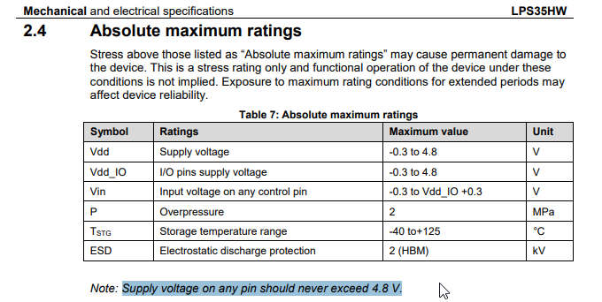
I'll have to look into what the resistor pullup stuff is, not sure I understand
stuck coral
(1.7-3.6) + 0.1 is the operation range, and if you give it a 3.3V VDD the IO voltage will also be 3.3V which is why its annotated that way
If you put 1.7V on VDD, then the IO will operate with 1.7V
hoary canopy
Ah so one thing I didn't know is that even though I provide 3.3v power, the arduino uno uses 5v on the digital ouput lines
(If I got that right)
stuck coral
Yep, remember my anti-UNO post? exhibit Z^
hoary canopy
That explains why the data lines go through the 5->3.3 circuit, correct?
stuck coral
Correct, thats right you are not getting the breakout from adafruit
Which has a level shifter, yep
hoary canopy
So out of curiosity, how does the arduino manage reading the pins back? Since the data signal will be in 3.3v
stuck coral
There was a good post online I shared before that explained this... cant find it now.
I see anon has got it and I got food so gonna let him explain
hoary canopy
Thanks for all the help by the way
reef ravine
the level shifter is bi-directional and on the sensor side the pins are pulled up to 3.3v, on the other they are pulled up to the voltage of the controller (i.e. 5v)
reef ravine
the pullups on uno side go to 5v, on the sensor side to 3.3
there is a level shifter on the sensor
pulsar junco
any idea why they don't use an IC built for I2C level shifting?
reef ravine
why not just generic? SPI, I2C...
hoary canopy
That chip supports both SPI and 12C
hoary canopy
So about the pullup resistors. I understand they're there so that the line reads as "High" even though nothing is connected. But... why?
reef ravine
most devices use inputs which draw almost 0 current (high input impedance), a pullup holds a pin high until it's pulled low. if left "floating" behavior can become undefined
there are also pulldowns
hoary canopy
Ah I think I understand
So basically the sensor isn't able to provide enough current to make it seem like a high circuit when it is high?
reef ravine
on a logic circuit you want HIGH or LOW only, not "a noisy voltage in between"
it's not that it can't provide enough current, you barely need any
it's just that the output is "open drain", the device can positively pull the output LOW, only through the pullup does it go HIGH
this allows the output to be used with a range of voltages
stuck coral
CMOS vs open drain - https://cdn.eeweb.com/articles/articles/image5-1350338401.PNG

 reef ravine
Complementary metal oxide semiconductors use N channel and P channel devices to actively pull the output high or low
hoary canopy
Electrical engineers really love abbreviations huh 😛
reef ravine
love those TLAs 🙂
stuck coral
Funny, not the first person to comment that but yeah otherwise we'd be here all day
Spacetime is 4D, the 4th dimension is not time its money
reef ravine
lol
hoary canopy
So are these pullup resistors a kind of backup system in case there is a problem? I understand why it's a bad thing to have a voltage "in between", but I'm not sure in what case it would happen
reef ravine
no, they are necessary for proper operation
stuck coral
So if you look at the open drain example, there is a transistor to bring the signal to ground, so when that transistor is not pulling to ground, the pull up pulls it high
hoary canopy
The way I see it, the sensor inside would toggle the wire the same way I would using a button or something, just really fast. So either there is current, or there isn't 🤔
stuck coral
Then the input is either at ground, or the HIGH voltage
reef ravine
a floating input can act as an antenna, just moving your hand too close might affect an input
hoary canopy
Open drain is the right one in the image?
stuck coral
Correct
hoary canopy
Sorry I'm not sure I understand why the floating position happens. Reading here https://learn.sparkfun.com/tutorials/pull-up-resistors/all it says
If there is nothing connected to the pin and your program reads the state of the pin, will it be high (pulled to VCC) or low (pulled to ground)?
I understand the problem in their case, but in this case the sensor pin and the arduino pins are always connected
stuck coral
But if you look at the picture I sent on the right, if the sensor disconnects the ground to send a 1, and the arduino is an input, then nothing is connected but the input
Then you have an antenna
But when it sends a 0 and connects to ground, then the input is connected to ground
hoary canopy
So we're talking about the time while the sensor is shifting from low to high?
stuck coral
Right, when its high, there is no way for it to put a voltage on the pin, only pull it to ground with the single transistor as shown
Which with I2C is nice
Then you can use pull ups to set the IO voltage
hoary canopy
there is no way for it to put a voltage on the pin
"It" being the sensor?
stuck coral
Correct
hoary canopy
Why isn't it able to?
stuck coral
Well look at the transistor config in the photo, there isnt a transistor between the HIGH voltgae and the ouput
Vs the CMOS that does
hoary canopy
I think I'm very confused 🙃 sorry for bugging you so much
reef ravine
another way to look at it, when the transistor is turned ON, the Out is definitely connected to ground
when OFF what is Out connected to?
(answer, nothing, it's "floating")
hoary canopy
I'm not certain that I can read that diagram properly, will have to read on how the transistor symbol works there
reef ravine
now, if you connect Out to a voltage through a resistor the output is pulled up to that voltage when off
stuck coral
Here its working like a switch
reef ravine
think of the transistor as a switch, voltage on the gate (the input on the left) closes the switch, if no voltage the switch is open
in this way a small signal can control a larger load like a motor, relay or lamp
hoary canopy
AH
So the connection between OUT and Gnd would be only there when the transistor is receiving voltage
reef ravine
by George I think he's got it 🙂
hoary canopy
And my next question would be, why not just connect the VCC to OUT
But I assume that's a nono because it'll short when the transistor is On
reef ravine
correct, it would be a "short" and do no useful work (other than perhaps releasing the magic blue smoke 🙂 ). Now connect a resistor from Vcc to the transistor out
when ON the out is connected to ground, when OFF the Out is pulled up to Vcc
hence "pullup"
hoary canopy
"transistor out" you mean the pin labelled output?
reef ravine
yes, connect a resistor between OUT and <your positive voltage> (it could be 5v, 12v, whatever volts in general)
hoary canopy
Wouldn't that still short, same as before?
reef ravine
no because the resistor resists the flow of current. of course you would pick a value which is high enough to limit the current to a safe amount for your device
hoary canopy
By doing this, aren't we wasting a good deal of energy? There will be a constant current going through that resistor?