#help-with-arduino
1 messages · Page 77 of 1
 stuck coral
You know how many chinese hoverboards there are?
 zenith orchid
well yeah...but if you find out which chip it's using
then you can move forward with that and figure out how it's been programmed
stuck coral
Then you need to reverse engineer how everything else on the board works, and write all the firmware from scratch
The how its been programmed is the first sub step
zenith orchid
But I just don't get it...
I'm connected right now to the board and my computer can see it
yet I legit can't do anything
zenith orchid
Well yes...but I connected the UART ports on the motherboard to the Arduino and now the beeper that's on the motherboard is just beeping...
so that tells me it's connected, and my computer is identifying it as plugged in
zenith orchid
Under device manager.......COM4
stuck coral
Which is the arduino USB UART IC
If you disconnect the hoverboard you will still see that if you leave the arduino connected
zenith orchid
ugh
okay
well then...shoot
I'm just back to where I started...
How would I even be able to plug this debugger in though....the only way to plug in is through UART
stuck coral
There should be a programming header somewhere that isnt the uart. It can just be bare metal pads
Best bet is to find the pins on the chip and follow traces
zenith orchid
yeah there is one...but it looks just like the UART ports...and it's not marked
So their are three places to plug in
not two sorry
without markings though
how do I know where the wires plug in
stuck coral
Yep, programming ports are usually not marked. And you would need to figure it out with a multi meter
And the data sheet
zenith orchid
okay I can do that..I have the meter....but the data sheet...I have no idea
stuck coral
I sent you the datasheet
stuck coral
It will tell you which pins are for programming
On the IC
Then you can use the multimeter to see which pad connects to that pin
zenith orchid
what do you mean pad?
stuck coral
So their are three places to plug in
zenith orchid
Yes each has four pin holes
five sorry
See how their are two that are horizontal and one is vertical
I think that vertical one could be the programming one
stuck coral
Find the programming pins on the datasheet on the chip itself, then either follow the traces or use a multimeter
zenith orchid
There's like five chips though on this one datasheet
stuck coral
How many pins are on one side of the IC?
stuck coral
I am working while Im helping you, could you give me a count please?
zenith orchid
25 on the right side
25 on the bottom
I sent that so I could view it on here 😛
25 on the left
25 on top
So each side has 25 pins
zenith orchid
So what would the label be for the programming pins
 woven mica
The programming pins are a pair PGECx and PGEDx
stuck coral
Pin 26 is a programming pin, they are labelled PGECx and ....^
Ouch I see pin 26 goes to a test pad, lol
zenith orchid
Yeah those pins don't lead to any of the UART ports......I'm seeing the top left corner pins 95 and 94?
those do connect to the UART
zenith orchid
but those pins actually do connect to the UART...I messed up
Looks like that one UART port that was vertical is our winner
stuck coral
Do all the programming pins go to it or only one?
zenith orchid
Well in the photo you can see 27 goes into a resistor
and 26...I can't tell where that goes
stuck coral
Looks like a capacitor to me
But anyways, even if you found it, you dont have a firmware file
woven mica
Pins 69 and 70 go to the connector
stuck coral
Or an external programmer
zenith orchid
69 or 70..I don't have access to those...they bridge off into a bunch of ics
Well I can get one...I just don't know what I need or how to hook it up
stuck coral
But do you have a firmware file, or the time and knowhow?
zenith orchid
I have the time...know how...not really....firmware file...no because it came from china
stuck coral
Remember that this isnt an arduino, PICs have very minimal boilerplate and you will not only need to learn how to just use C without a framework, but also you'll need to reverse engineer the entire board
zenith orchid
So then what am I suppose to do......I have six three phase dc brushless motors that also have Hall sensors I believe...and I'd like to get them all working together so I can move forward and back
stuck coral
Well I dont have the time to invest to work on the project with you
zenith orchid
That makes sense 🙂
woven mica
Its probably easier to use three ESC controllers
zenith orchid
Yeah that's what I'm thinking...but I'm not sure which ESCS can handle two 350w dc brushless motors
Plus I have three 32v volt batteries
woven mica
something like this maybe https://www.ebay.com/itm/100A-960A-14-32V-Brushed-ESC-Speed-Controller-fr-775-795-Brush-Motor-RC-Car-Boat/153742462137

eBay
This ESC is widely apply to RC tank, RC car, RC crawler, RC truck, RC Boat. - Support Motor: brush motor 540/550/775/795/D848 etc. - Motor Connector: xt60 female. - Power Connector: xt60 male. It maybe delay for hot sales season,Strike,bad weather,and so on.
zenith orchid
Those are for Brushed motors

Reverse engineering of Hoverboard YIYUN TECH YK99
Gyro board:
black = ground
green = UART TX (send from gyro board to motor board)
blue = UART RX (send from motor borad do gyro board)
red = +12V
Speed: 31500 bit/s
Level: 5V
bits: 9
party: no
stop bit: 1
Frames (from Gyro bo...
see this guy did it
with an Arduino
woven mica
ok, but there shold be that current for brushless too
zenith orchid
Or something like this

WARNING: Adding a heat sink will short the circuit. The body of the transistor is positive voltage, and the heat sink will be grounded through the mounting screws.
Powerful wheel and controller you can use in a robot project.
350 watts for about $40!!!!
Amazon and eBay an...
but then I'd need six controllers
and six Arduinos???
woven mica
one arduino can control them all
zenith orchid
So then I need six of those controllers
woven mica
If you cant control those PIC boards, yes
zenith orchid
Yeah I think I'm just going to drop the PIC board idea
seems way to complicated for my knowledge base
it would be freaking cool
woven mica
wait, for each motor you need just one
zenith orchid
but It wouldn't make sense I don't think
Right but their are six motors
Three sets of two

eBay
Maximum power: 350W. This driver board can be fit for DC brush less without hall sensor three-phase motors. MA MC: phase line output connection motor. Maximum current: 16A. Over current protection: yes.
would this work?
Why did you say I'd only need one?
Are you still here?
@woven mica
I think I found the ones I'm going to buy
But they are for 500w Motors
that shouldn't be an issue though right
since these are 350w
woven mica
You can use one arduino to drive them all. More watts is better, they will heat up less.
zenith orchid
Alright cool
just bought six of them
Delivery is going to take foreverrrr though
woven mica
Its standard to have about month shipping from china
zenith orchid
Ugh that just suckssssssssss
Now I gotta wait
well atleast now when they get here though, I'll be able to wire the thing up and get her moving
woven mica
Ok I go to bed, good luck
zenith orchid
Thank you 🙂
Pretty exciting
ngl
Would it be an issue if the board didn't have hall sensors
zenith orchid
Just picked up six of these
Which wires will I have to splice in order to get all six of these running on one UNO
 north stream
@zenith orchid I'd recommend https://www.adafruit.com/product/3567 for running high power DC motors

RageBridge 2 from Equals Zero Designs is a no-frills and robust dual-channel DC motor controller for robotic and vehicular drivetrain applications. It can supply 40 amps per side ...
north stream
Correct.
zenith orchid
That's crazy.....why is it so much
I just bought six for under a hundred
Why are you suggesting these
north stream
They're nice solid reliable controllers. Didn't know you had already chosen something else.
zenith orchid
Yeah I went with these

aliexpress.com
Smarter Shopping, Better Living! Aliexpress.com
north stream
Those are for brushless motors, I thought you wanted DC motors.
north stream
Ah, they are brushless. I misunderstood.
zenith orchid
All good, kinda scared me though
 candid wren
anybody work with the twitch api before? I want to make something that reacts to new/returning subs.
 wanton scarab
hey all, a moderator suggested i try in here, so here it goes, would somebody be willing to look over my code and give me pointers where i could improve it? its relatively simple. it just turns on a neopixel strip, changes colors, and sends a keyboard stroke. would love some feedback for learning purposes.
 gilded swift
@wanton scarab upload your code to pastebin or similar and share the code with the channel
 young flint
does anyone have any good resources for transmitting data wirelessly to a computer using arduino? i've never done anything like this and i guess i'm mostly wondering if i should use bluetooth/wifi/something else?, and if i have multiple devices transmitting data do they all need to have an arduino?
young flint
i'm making two gloves, one will be transmitting readings from 3-4 flex sensors and a gyroscope, and the other will be transmitting a pressure sensor output and a gyroscope output
stuck coral
I think you would want bluetooth low energy, using a GATT service and use notifications to push data to a client
young flint
awesome thanks! i'm googling those things and i found some good resources on the adafruit website, i'll probably be back if/when i have more questions loll
stuck coral
You're welcome, could you fit one of these? Then all you would need is this and a battery for fully functional system - https://www.adafruit.com/product/4516

The Adafruit Feather Bluefruit Sense takes our popular Feather nRF52840 Express and adds a smorgasbord of sensors to make a great wireless sensor platform. This Feather microcontroller comes ...
Digikey has them stocked, since adafruit is out
young flint
i was just looking at that! i was thinking a flora or lilypad as those were meant for wearables but this might be better as it has bluetooth built in
i'm looking at the circuit playground bluefruit too i just need to count to make sure it has enough pinouts for what i need
stuck coral
Whoops I replied to the wrong channel but glad that works for you XD
But yeah you want to look into BLE gatt which will inform you how the BLE communication works and when you setup the device you will use a c++ library to setup gatt
wanton scarab
@gilded swift will do. Had to step out to grab food real quick
wanton scarab
https://pastebin.com/pcq7RR41 alright here is the pastebin
Pastebin
Pastebin.com is the number one paste tool since 2002. Pastebin is a website where you can store text online for a set period of time.
everything works as intended. the 2 issues i'm having are 1. the white light should stay white. right now when i release the button it switches back to color. id like that button to switch between color and white. 2. when i switch to white and back to color it resets the color. i'd like it to save the last color so you can quickly switch to white and back. so for example if i set the color to green, then press white and go back to color, currently it resets it to red which is the first color. id like to be able to switch from green, to white, back to green quickly. those are the last 2 things i need to sort out. as far as the code, it be great to get some pointers where i could optimize it or just improve.
gilded swift
     {digitalWrite(13, LOW);                      // turn onboard LED on/off for debugging button
     }
  else
     {digitalWrite(13, HIGH);                     // turn onboard LED on/off for debugging button
     colorState = colorState + 1;                 // get the current color state and add 1 to go to the next state
     LastcolorState = colorState;
     delay(200);
}```In that section there is causing the color change on white
need some additional logic to check if the LED color is white or not
 pine bramble
not sure if anyone knows the answer to this, but how would i change the mode on my metro m0 from supervisor to user?
i'm assuming i need to use inline assembly or modify some registers
(is this even possible on the metro m4?)
stuck coral
Cortex M4 is basically a M3 with DSP-
From page 2-3 of Cortex-M3 revision 2 TRM:
"Thread mode is privileged out of reset, but you can change it to user or unprivileged by
setting the CONTROL[0] bit using the MSR instruction."
stuck coral
And this link talks about it more http://www.vlsiip.com/socsec/socsec_0004.html
 halcyon bramble
is there a way to control how much voltage v outputs?
digitalWrite(2, HIGH);
rather than just using "HIGH", can I set the output voltage?
 vivid rock
not on a digital pin
halcyon bramble
what would be the alternative then?
vivid rock
you can use pwm - on a pwm-capable pin
but if you really need to set voltage, you need a digital-to-analog converter
known as DAC
some boards have that, but this is rare
wanton scarab
https://pastebin.com/1VbRwsJx @gilded swift i solved it with the help of a buddy. we spent the past hour or two sorting through this but it works now 🙂
Pastebin
Pastebin.com is the number one paste tool since 2002. Pastebin is a website where you can store text online for a set period of time.
if anybody could do a final look over it and see if i can clean it up anywhere i would appreciate it. first time programming but its working
gilded swift
glad to see you got it working 👍
zenith orchid
How many different bldc motors can you control if you spliced the wiring...off an ardunio uno
Cause I need 24 inputs but I only have 16 on the mega....and I'm wondering...am I just fooling myself....do I even need to do that? I bought these very generic 500w motor controllers...and each one needs to plug in four times. So I'm thinking...what if I spliced all of those input wires....
Then I could have the mega running all of the motor controllers....cause theirs no real current through those....right?
north stream
@zenith orchid You can just tie the enable inputs high. The speedometer pin is an output (not an input) and you may not need it.
That just leaves forward/reverse and speed control. Note that speed control is an analog signal, something an Arduino can't provide anyway.
halcyon bramble
On this line of code in the Arduino Example library, why do they divide by 1023 then multiply?
float voltage = sensorValue * (5.0 / 1023.0);
 cedar mountain
The analog to digital converter for that chip gives a 10-bit value, which has a range of 0-1023. So if it spans a 5V scale, that's how you'd convert the numerical count to a physical voltage.
halcyon bramble
oh
so could I also convert it to a RGB value by using
sensorValue * ( 255.0 / 1023);
Yep.
 plucky tundra
Hi, does anyone have experience using DS3231 RTC?
been trying to communicate with it
writing to register works via wire library BUT reading the second and minute register doesn't seem to work and always return -1
  Wire.write(0x00);
  Wire.endTransmission(false);
  Wire.requestFrom(RTC+1,2,true);
  secTemp = Wire.read();
minTemp = Wire.read(); ```am I doing something wrong?
north stream
You may need to read before calling endTransmission
plucky tundra
nope, not solving the issue :/
okay found the issue
turns out the datasheet was wrong and if i want to read i should write RTC i2c address, not RTC i2c address + 1
jesus
north stream
Good job figuring it out!
north stream
I know that feel!
 reef ravine
@wanton scarab Take a look at this, a different way to tackle your code from last night, be back on later if you care to discuss. https://pastebin.com/9qpTgPKC
Pastebin
Pastebin.com is the number one paste tool since 2002. Pastebin is a website where you can store text online for a set period of time.
pine bramble
Looking foe a way to have 30 buttons on a project, and need to be able to sense when more than one is pressed. So that means no matrix or resistor chains. Not finding any IO expanders that will do more than 16, and I'm using the pins those use anyway. Is there any hope for me?
cedar mountain
I mean, the obvious answer would be to use multiple I/O expander chips. You can put multiple ones on an I2C bus, even with other devices too, so I'm not sure what you mean by "using those pins anyway".
wanton scarab
@reef ravine i will take a look, thank you and by all means, if you want to message me when you are free i'd love to discuss 🙂
pine bramble
I'm already using SCL and SDA for a time of flight sensor. So you're saying I can use those for multiple devices?
vivid rock
i2c is a bus - you can put many devices on it, and it will work fine as long as
- they all have different i2c addresses
and 2. you are only talking to one device at a time
pine bramble
Awesome, I'll dig in on that topic. Thanks folks!
north stream
@pine bramble You can use switch matrices and still detect multiple keys pressed at one time, but it would need diode isolation if you also needed to avoid "ghost keys". The HT16K33 chip, while designed as an LED driver, also supports up to 39 keys in a 3x13 matrix.
pine bramble
It looks like I'm going with two Sparkfun IO expanders. Which is great, as it makes everything a bit more straightforward, and it has just the right number of ports for each 15 button part of the project.
north stream
That's a nice clean solution.
pine bramble
I would have purchased it at adafruit, but they don't offer one for arduino. Just a chip. 🙂 /hinttoadafruit
north stream
Not sure which I/O expander you're using, or what "for Arduino" means here (maybe a shield?)
 boreal sentinel
Hello guys! I am thinking about building an LED controler over Internet (using a board with ESP8266 wifi cheap) and I want to be able to controle it via a mobile phone. What should I be using for an instant response? A web server, UDP/TCP packet parser? What do you suggest? (I don't really want the easy way, I want a way that's the most efficent)
pine bramble
How instant is instant.
boreal sentinel
10-20ms
not to wait too much I mean if I want to switch from all rgb lights using an app
this should be able to recieve and switch as fast as it recieved
pine bramble
what's 10-20 ms in a repetitive cycle? (in kHz or mHz).
10 ms is 0.1 kHz.
(100 Hz)
50 Hz is 20 ms
So, near CRT refresh or commercial power line frequency.
Those are low signalling rates.
In Linux you can 'ping' to get an estimate of latency.
I have no idea what the typical magnitude of internet communications latency would be.
north stream
There's a lot of back and forth for HTTP, but UDP is pretty fast, especially if you don't need guaranteed packet delivery.
 obtuse spruce
The choice of UDP or TCP has a lot to do with the characteristics of the application - the latency will be pretty much the same for a local network path.
HTTP is much more chatty... but 10ms is pretty long in network time.....
So, it would be important to know what is driving the 10~20ms response time - and how often you expect the mobile phone to update it.
Also - how mobile? Same WiFi network? Or is the phone, say, in another country?
Also - for this application, where is latency measured from? User tap on the screen to led change? Command from app sent to sensor on phone seeing light change? Etc....
pine bramble
Hello, these days i was trying to put my arduino uno R3 in dfu mode, but it won't go in dfu mode could someone help me? the microcontroller is atmega16u2 1640
i already try this tutorial
and doesn't works
I think flying drones by remote involves local 'intelligence' to keep the aircraft from doing something wrong while AFI (awaiting further instruction).
north stream
Do you have a link to the tutorial? What are you using as a DFU programmer?
pine bramble
Open-source electronic prototyping platform enabling users to create interactive electronic objects.
i try with atmel flip and dfu-programmer at kali linux and return to me "dfu-programmer: no device present."
north stream
Ah, it's supposed to program directly over USB.
Does the serial port still show up?
pine bramble
yes
north stream
Then it's probably not in DFU mode
pine bramble
when i remove the jumper arduino won't go to dfu mode and shows you as if you were connected normally
dfu-util iirc
Adafruit's tech info on their STM32F405 Express talks about DFU.
That's Mac and Linux oriented help with dfu-util (I'm supposing it's not made available in Windows).
The pointer in that link isn't functioning with my browser. ;)
Use this then scroll down a little:
https://learn.adafruit.com/adafruit-stm32f405-feather-express?view=all#step-3045691
Nope.
Stuff Disappears when you use either of those links I provided.
boreal sentinel
Can someone help me to wire up an arduino esp8266 for a 10 meter LED SMD5050? I am in a bit of struggle
north stream
Are these addressable LEDs or what?
boreal sentinel
no
non adressable @north stream
give rgb
and all have the same output
but still can t manage to link them
north stream
The usual hookup for those is to use transistors to control the LEDs and the ESP to control the transistors.
gilded swift
It's possible that the transistors are not driving hard enough. What's the rating of the supply you're using?
also, maybe unroll your LEDs, it isn't a terribly great idea to operate them rolled up like that
north stream
Could be a flaky connection too, pushing TO-220 leads into solderless breadboards can flex the contacts enough that nearby ones don't get a good connection.
north stream
I'd try swapping signals to see if the problem moves with the I/O pin, the transistor, or the LED strip
boreal sentinel
I tried to switch them all
Nothing it s working
Even tried to switch the board and still nothing
Led strip 100% works because when connected without transistors RGB are all at HIGH
north stream
You say "nothing is working" but in the picture, you had a cyan color, which implies that the blue and green channels are working.
boreal sentinel
Yes but only one is at 100% power
Others are always at 10%
Or dim light
And it s always the same pin
gilded swift
I’d be willing to say you do t have enough current from the LED source to drive all three colors
One hogs while the others are starved
boreal sentinel
I have the 12V soruce that powes the same 10M led band
But on the old circuit
So the powersource it s no issue
There are 3 mosfets so they are no issue to
And the rezistence is 1k oh@
Ohm
(The test band is 3m long)
gilded swift
Instead of tying your base resistors to ground, just connect one end to the base and one to the esp GPIO
I get what you’re doing with sending it to ground, but it’s may not be necessary in this case.
Alternatively, add a second 1K resistor between GPIO and base and keep the existing 1K between base and ground
boreal sentinel
I will try to do that. Btw a circuit without resistors may or may not work? I saw a schema without them
gilded swift
Mosfets don’t necessarily need resistors driving the base since they are inherently voltage driven devices
BJTs on the other hand need current limiting resistors on the base at a minimum
Whether or not you have one on the collector/emitter is depending on the load.
But @north stream could probably explain this much better than me (they are super helpful)
north stream
Perhaps the I/O pins are different, or configured differently.
For example, if a pin is set as an input pin, but a logic high is written to it, this can be interpreted as enabling the pull-up resistor, which will only turn on the transistor weakly.
 safe geyser
Have a question about losing Serial when using Arduino with the STMF405 Feather ... Is there something I'm supposed to be doing after I load my sketch?
reef ravine
@safe geyser check these settings https://learn.adafruit.com/adafruit-stm32f405-feather-express/arduino-ide-setup
 wraith current
@safe geyser most of the feathers use the usb serial chip for programming so the Arudino IDE terminates your serial monitor connection in order to program. Then when it's done you can re-establish. I usually wait until programming is totally complete, then click on the serial monitor window to bring it back to the front. It usually reconnects automatically at that point.
boreal sentinel
Is it there a way to amplify this to make it brighter?
 elder hare
im in a blank here
void drawXbm565(int x, int y, int width, int height, unsigned long *xbm, uint16_t color = 0xffff)
{
  if (width % 8 != 0) {
      width =  ((width / 8) + 1) * 8;
  }
    for (int i = 0; i < width * height / 8; i++ ) {
      unsigned long *charColumn = xbm + i;
      for (int j = 0; j < 8; j++) {
        int targetX = (i * 8 + j) % width + x;
        int targetY = (8 * i / (width)) + y;
        if (charColumn, j) {
          matrix.drawPixel(targetX, targetY, color);
        }
      }
    }
}
    if (doc["pixArt"])
    {
      JsonArray src = doc["pixArt"].as<JsonArray>();
      int i = 0;
      for (JsonVariant p : src) {
        if (i >= 1024) break;
        MyMatrix::pixelArt[i++] = p.as<unsigned long>();
        Serial.println(p.as<unsigned long>());
      }
    }
Error
assignment of read-only location 'MyMatrix::pixelArt[(i ++)]'
why?
pine bramble
It's not often two colons are seen in code outside of a library.
It's a C++ ism and isn't straight C.
elder hare
@pine bramble what that to me?
pine bramble
Yes.
Adafruit writes a lot of example programs; I've seen many of them.
They seem to restrict the use of an :: code utterance to libraries.
I don't know enough C++ to say it more plainly.
My guess is that it doesn't belong in the .ino file nor your own .cpp file.
elder hare
MyMatrix is a namespace tho !
 lone ferry
How is pixelArt defined?
elder hare
@lone ferry
unsigned long pixelArt[1024] = { }; // Matrix pixelArt Array
;)
The error message is probably in the compiler output's scrollback.
Only the first error is reliably accurately reported.
Depending on the nature of the errors, it's often efficent enough to work on the last error reported.
Sometimes the last error is just not reflective of the reality of it.
lone ferry
Also, it would be good to see the definition in the header file.
pine bramble
Or more simply: post all the code, for any question asked, ever. Ever. Ever. ;)
I like to post up to five lines of code here in the channel, and also link to the exact context, on a functional github repository.
After jumping through all those hoops .. by the time you've documented your question properly, you may very well notice its solution. Possibly, prior to asking about it, publicly.
If I have time (or make the time) I'll often turn on all compiler warnings, and systematically remove them (by editing my code).
That way an important warning will be easily noticed, as it'll be the only exception.
Arduino IDE prints them in orange. After a major upgrade of the IDE, those orange text reports usually increase. ;)
obtuse spruce
@elder hare the code you posted does not match the code in the error message.
north stream
@boreal sentinel yes.
pine bramble
My arduino just doesn't go into dfu mode.
When I disconnect the jumper it recognizes that it is not in dfu mode. Any solution?
north stream
It looks like it goes into DFU mode, but only briefly?
pine bramble
i think it isn't goin into dfu bc when i try to use dfu-programmer it returns to me "dfu-programmer: no device present"
safe geyser
@safe geyser most of the feathers use the usb serial chip for programming so the Arudino IDE terminates your serial monitor connection in order to program. Then when it's done you can re-establish. I usually wait until programming is totally complete, then click on the serial monitor window to bring it back to the front. It usually reconnects automatically at that point.
@wraith current Thx. I tried that but it doesn't seem to re-connect. I get a "Board at COM15 is not available" message. Is there something else that I need to do?
pine bramble
In Linux you can run a separate telecomm program (like HyperTerm in Windows, I think it's called).
Different comm programs assert the right to use the port differently from others.
So I would try all the popular ones to see which one behaves most compatibly.
Some have command line options regarding this.
picocom will quit without touching the port.
So it's reentrant, iirc.
Standard behavior is to initialize the port, and possibly dump some Hayes AT commands onto it.
(the dominant application for such terminals, until kind-of recently, was modem use, to talk to the Hayes command set/interpreter built into the modem)
I'd say our use case is now dominant, for that, but it's a guess.
 trail wing
Anyone here with a somewhat deep understanding of the u8glib? thought this the best place to ask despite being a mix of arduino and PIC micro.
I'm trying to get it to work on a PIC18 micro. However, with the new architecture, user has minimal control over start/stop conditions. Its all done in hardware based on a "bytes to transmit" counter.
Any quick way to get the library to pass number of bytes to u8g_i2c_start, not just slave address?
pine bramble
https://github.com/olikraus/u8glib
Note: There will be no more development for U8glib. Please use u8g2.
stuck coral
And @trail wing there should be another function that you use after sending an address that lets you write to or read from a register with any byte data which in this case would be your number but I am not familiar with this lib
With I2C, you select a device address, then you send that device data
trail wing
@stuck coral I know, that's how you did it pre K42. The K42 Quite literary wants the following, everything else is done in hardware:
void writeI2C(unsigned char slave, unsigned char dataBlock[], unsigned char dataLength){
    unsigned char totalByteLength = dataLength + 1 /* addressLength */;
    // Write operation (W/R bit = 0)
    I2C1ADB1 = (slave << 1) | 0;
    I2C1CNT = totalByteLength;
    for(i = 0; i < totalByteLength; i++){    // Write to TXB starts communication
        I2C1TXB = *dataBlock;
        dataBlock++;    // Wait until TXB is empty
        while(!I2C1STAT1bits.TXBE);
    }
}
I dont know what you mean by pre k42, i2c is a specification and its doing the same thing
trail wing
I know. But this abstraction layer requires a total byte count.
stuck coral
Doesnt matter in hardware vs software, the register selection is not required in i2c. I dont get your point on the last message
trail wing
The problem is I cant generate a stop condition. Cause start and stop bits is determined by the I2CxCNT register's value upon the 9th clock edge transition.
Might be possible to disable auto-decrement of CNT and set it to 1 at start and manually force it to 0 on "stop"
stuck coral
Is there a function to put data into And with i2c libraries commonly there is a stop transaction function or similardataBlock?
(Idk if you have done this yet, but as nis suggests you should move to the new library if you can before you figure out the ins and outs of this one)
trail wing
As I said, there is Nothing more to the whole transmission than the code above. The issue is splitting the above posted (microchip provided) method into a start/send/stop set of methods.
And no, I'm not using any I2C library because its totally unnecessary for master operation.
Or, to make g8u library pass a byte-count to start 🙂
stuck coral
I think I am misunderstood the issue, and I need to go, but I bet someone here will give a great answer, it requires more digging into exactly what you are doing.
pine bramble
why does Adafruit-PCD8544-Nokia-5110-LCD-library allocate a 504 byte lcd buffer?
the controller chip already has a 504 byte buffer, so this seems kind of like a waste of memory
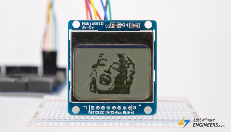
Learn about Nokia 5110 Graphic LCD Display module along with its Pinout, Wiring, Library & Arduino Code for Displating Text, Drawings & Bitmaps
The PCD8544 LCD driver has a built-in 504 bytes Graphic Display Data RAM (GDDRAM) for the screen which holds the bit pattern to be displayed.
boreal sentinel
@boreal sentinel yes.
@north stream How? I mean I tried adding some resistors and it s better now but it s not the maximum ammount
north stream
I don't know enough about your setup to offer specific advice
north stream
Not necessarily, I'd still need to know about your power supply, code, etc. as well
To put it another way, there are lots of possible causes for dim LEDs
They can be fixed, but it can take a while to figure out what's happening, and the proper changes to make.
pine bramble
nvm, figured out the reason
the controller chip only allows the entire display to be updated at once
so this buffer is required
north stream
Ah, I was curious too after you posted that. Thanks for researching it and sharing what you found!
 grand basin
Hi everyone. I have a very ugly code that I would like adapted so that it only transmits serial midi, omitting any usbMIDI aspects of it, as the device I'm transmitting to gets confused receiving usbMIDI information, if that makes sense
It was too long to post and you'll see why. I'm not confident in creating an array for the pots (if that's the correct terminology, not even sure)
if I wanted to do that, would I just change all of the "usbMIDI" commands to "MIDI" and add the <MIDI.h> library, create midi instance, and Serial.begin(31250)?
Teensy 4.1 by the way
trail wing
@stuck coral Just for an update, I got a reply at the Microchip forum, and they said to either update the library to support the K42 abstraction, or bit bang, or figure out another work-around
The K42 architecture abstracts the I2C too far to be directly compatible
stuck coral
Yeah that sounds like a reasonable response
 fervent roost
hey -- I have a data types question. I'm using the esp32 ble library to receive data from notifications from a server. I know what a sample set of data looks like and know how to decode it in javascript https://stackoverflow.com/a/64004591/2332633 but I'm having some issues translating the uint8 pointer that my callback receives into C, would anyone be able to help me convert the js code into C that I can use with my esp32?

Stack Overflow
I'm trying to use the Fitness Machine Service + the Indoor Bike Data characteristic to get the cadence data. By using the nRF Connect Android App I can see that the data is there, sample data:
inst.
stuck coral
Are you trying to send/recv object type data @fervent roost?
wraith current
@safe geyser I took a look at the product page for the STMF405 Feather and I think your problem probably steps from the use of the USB DFU bootloader it uses. Also this :
stuck coral
@fervent roost ah I read the link you posted, you need to choose a encoding for transport. Commonly JSON, protobuffers, or XML is used
I like protobuffers but they are a bit of work to setup, however I argue its worth it and for microcontrollers it is very low overhead and fast
In theory you could make it work with the encoding used in that stack overflow question, but it seems a tad memory intensive for a micro. I think even JSON would take less memory and its super easy to encode object in javascript in JSON
Better be
Hence JavaScript Object Notation
fervent roost
do you have an example of what you are referring to? This is essentially the callback that I have to create https://github.com/nkolban/ESP32_BLE_Arduino/blob/master/examples/BLE_client/BLE_client.ino#L22-L33

GitHub
The library source for the ESP32 BLE support for Arduino. - nkolban/ESP32_BLE_Arduino
stuck coral
For BLE, if you are trying to send an object in a characteristic callback, I find protobuffers to be a great tool
My current project at work has BLE and there is nothing better than protobuffers once you figure everything out
fervent roost
I don't think that I need to send data to the characteristic since the device itself is the one sending data, I would just have to react to the data it sends
stuck coral
You are trying to encode an object correct? And you are trying to send it through BLE on either a read or a write to a characteristic correct? No matter the direction
The only other option with lower overhead both in the amount of data you send through BLE, and memory consumed on the arduino (Which, BLE stack makes memory a bit of a luxury) is making your own byte protocol by hand. And the fact you make a schema document then protoc auto generates the code for you for both the C and javascript side is awesome. It makes it very easy, and you can be sure that the object you send will be received the way you want it to
But, notice the focus on objects
north stream
That's not the only option, there are things like Firmata
stuck coral
True, does it auto generate all the javascript you need?
Google have perfected it and it is magic
Also auto generates golang, PHP, C for embedded, C for big boy computers, define one file and you have everything you need for every language you would be using.
Also, Firmata is not the same thing at all, that looks like a control protocol
fervent roost
might be clearer if I give more context. I have my indoor bike which can transmit data through BLE, data like cadence, speed, etc. The characteristic that sends the data allows me to subscribe to changes in data that it sends. My idea is that I can display said information in a small oled screen. TLDR: BLE compatible device sends data and I want to display it with a esp32
stuck coral
I was placing a lot of focus on objects because if you just have a few values like cadence and speed, you can just make those two seperate characteristics and just send the raw value, then the client device can choose what to read or what to listen to for notifications or indications. You could use protoc and it still applies here, but with just a few values you can do what I recommend above or make your own super simple byte protocol.
I am making high polling measurement devices, and I write all the objects we would encode or decode when communicating to the mobile app, so that is on git as a schema file and whenever I build the C code always generates the most up to date version and the mobile developer can pull it and auto generate the code for his app to encode and decode all the objects we will exchange
And like I said before, very low overhead. But your situation you may not need or want this
halcyon bramble
I'm currently trying to print RGB values into the serial monitor. However, I can't find the formatting for multiple numbers on the internet.
Serial.println(round(red),round(green),round(blue));
When I use this line, I get a error. Can somebody help?
red, green and blue are all float red = redValue * (255.0 / 1023.0);, etc.
stuck coral
The sprintf function will help, are those floats or integers?
halcyon bramble
sprintf?
obtuse spruce
First - are you using an Adafruit core or some other?
halcyon bramble
arduino uno
stuck coral
Lol
Hold on I am making you an example, but you show round() being used, so you want to get an int back not a float?
(And I will need to check the new print functions, news to me)
halcyon bramble
does round() not work on float variables?
obtuse spruce
So - first, if you want to Serial print a float (or double), you must use this:
float thing;
...

Serial.print(thing, 3);   // 2nd argument is number of digits
so I don't use printIn
stuck coral
My code
char buf[128];
if(sprintf(buf, "%d, %d, %d", round(red), round(green), round(blue)) < 1){
  Serial.println("Failure sir!");
  return;
}
Serial.println(buf);
or, mzeros code
Serial.print(round(red));
Serial.print(",");
Serial.print(round(green));
Serial.print(",");
Serial.println(round(blue));
However, I think you should use mzeros example (Though its on the stack so unless you are already memory limited shrug)
halcyon bramble
oh
so I can't just combine multiple into one
i have to write a line of code for every time variable
stuck coral
The Arduino programming language Reference, organized into Functions, Variable and Constant, and Structure keywords.
I think that link covers it pretty well
Serial.println(val, format) has one value, not three, you are giving three arguments but the second is the format and the first is what you want to print and it can be many different data types
 frosty thistle
I always do mzeros method.
fervent roost
@obtuse spruce do you have a link to this Adafruit Print class?
frosty thistle
can squeeze a couple in on one line for tidyness sake
obtuse spruce
Oh - there's a println version as well....
stuck coral
Thats true, your wish of one line could be real Serial.print(round(red)); Serial.print(","); Serial.print(round(green)); Serial.print(","); Serial.println(round(blue)); 😆
halcyon bramble
frosty thistle
heh
frosty thistle
Does anyone have any experience with mcp23017 being really slow?
stuck coral
What I2C speed are you using? (Or SPI)
frosty thistle
I2C, and using the Adafruit_MCP23017 lib. I did not see any place to specify a speed anywhere.
stuck coral
I think after you call begin() you can just change the I2C speed as per usual, and also how are you reading the data?
Are you reading many pins at a time or just one?
frosty thistle
Its all outputs, and doing a m.digitalWrite(x, x);
One at a time, in fast succession
frosty thistle
Apparently I enjoy suffering as I am trying to use two of them to drive two 4 digit 7seg displays. haha
stuck coral
/**
 * Writes all the pins in one go. This method is very useful if you are
 * implementing a multiplexed matrix and want to get a decent refresh rate.
 */
void Adafruit_MCP23017::writeGPIOAB(uint16_t ba)
Just takes a 16 bit value, set the bit at the index of the pin number -1 and you can write to all the outputs in one I2C write instead of doing one output at a time and making many I2C writes per refresh
frosty thistle
Looks promising, but please excuse me for being a bit slow on this, been banging my head against this for an inordinate amount of time. haha
stuck coral
Sure
frosty thistle
This is just beyond me, I get using a 16 bit value but am not sure how to actually implement that.
stuck coral
Well luckily for you we acutally solved this in this channel before, are you just displaying numbers?
frosty thistle
yep
stuck coral
Okay, one second while I recreate the example because it was a while ago
Also, do you have a wiring diagram of the displays?
halcyon bramble
If I'm powering multiple LEDs with an arduino and I don't have enough power, do I just send voltage into the Vin pin?
frosty thistle
Awesome, thanks @stuck coral . I did search for mcp23017 in the channel before I asked, but a ton came up and didnt think there would be something that specific.
halcyon bramble
or is that not how it works
stuck coral
Do you have an LED driver or are you just driving LEDs with a pin?
halcyon bramble
with a pin
frosty thistle
I have some stuff that I wrote down. I know the digit pins and segment pins.
stuck coral
not how it works
@halcyon bramble this option
frosty thistle
idea was to drive the whole thing from the mcp. So just pins, no driver
also Its common cathode
stuck coral
If I remember right the mcp is just fine with a 7-segment display
frosty thistle
I know the wiring is correct, I can (slowly) set one number at a time and all the segments are correct.
stuck coral
Do you have multiple MCPs? Im trying to understand how you are driving 8 total digits of 7 segment display? common cathode
frosty thistle
sorry, ill clarify.
MCU is nano 33 IOT, 2 mcp23017's connected via I2C. Two 4 digit 7 seg displays, one for each mcp.
Thats the plan, I only have one connected so far since I was having issues.
stuck coral
But if they are common cathode, then that would be 28 anodes and you only have 16 pins
frosty thistle
Ah, I see what you are saying. Its a matrix. 4 digit pins, 7 segment pins
stuck coral
So I assume each digit has its own cathode? Which is common across said digit?
frosty thistle
(not to drag you into this too much, but here is the DS) http://www.farnell.com/datasheets/2049462.pdf
the digit pins are the common cathode
stuck coral
Yep okay, one sec while I make you a code example
frosty thistle
Right on, thanks. I feel like I have it mostly figured out. Its just reeeeal slow on the refresh
 narrow jackal
What is wrong with stepper.currentPosition() in the AccelStepper library? Somehow I can't send the result in serial or set it as the amount of steps to move
wraith current
@halcyon bramble you need a transistor to drive more current from arduino
@narrow jackal are you trying to do Serial.print(stepper.currentPosition()); ??
narrow jackal
Something like that, yeah
But I also can't do something like this:
void homePosition(AccelStepper myMotor, int SPEED){
 int current_position=myMotor.currentPosition();
 while (myMotor.currentPosition() != 0){
        if (-current_position < 0){
          myMotor.setSpeed(-1*SPEED);
          } else {
          myMotor.setSpeed(SPEED);
          }

        myMotor.runSpeed();
      }
}```If I set current_position to anything other than stepper.currentPosition() it runs perfectly
Something about it breaks everything
And it's harder to debug because for some odd reason doing something like
Serial.println("Current position: " + String(myMotor.currentPosition()));
the pi will not read and send that unless I remove the concatenated bit
wraith current
Doing string concats with function calls causes problems a lot, so try not to do that if it's acting weird.
if you Serial.print(current_position); does it give a sane value ?
A lot of times I'll just do a hacky workdaround like so :
and why is there a minus sign in front of this variable ? -current_position
stuck coral
@frosty thistle so you will need to make multiple writes per refresh of all four digits, but not one every segment of the display so this will speed the whole thing up 7x. I think I got the pin order a little funky but i dont feel like re-writing everything-
const uint8_t digits[10] = {
// A B C D E F G
  0b1111110, // 0
  0b0110000, // 1
  0b1101100, // 2
  0b1111001, // 3
  0b0110011, // 4
  0b1011011, // 5
  0b1011111, // 6
  0b1110000, // 7
  0b1111111, // 8
  0b1111011, // 9
};

uint8_t encodeDigit(int i){
  if(i > 9){
    return 0x0;
  }
  return digits[i];
}

void setDigit(int value, int digit){
  mcpClass.writeGPIOAB(encodeDigit(value)<<9 | 0b1111 & ~(0x1 << 3 - digit));
}
Oh hold on, need to fix a detail
wraith current
so current_position is 0 ?
narrow jackal
It is most certainly not zero
As you can see in the example I moved motor C 500 steps
And AccelStepper does track that
frosty thistle
@stuck coral Right on man, that looks like I can wedge it in to what I already have. Thank you! Might not finish tonight, but Ill let you know when I do!
You got a tip jar? haha
narrow jackal
okay it appears that for some unknown reason myMotor.currentPosition() returns zero
stuck coral
@frosty thistle been thinking of making a Ko-Fi 😆 You're welcome, if you need help with the pinout come back.
wraith current
@narrow jackal this might be a shot in the dark, but currentPosition returns a long int and you are assigning it a normal int, try doing
long current_position = stepper.currentPosition()
narrow jackal
okay
wraith current
but also note, that after a restart of the Arduino it loses track of where the steppermotor is. Is that was RESET means or are you just using that term to mean something else ?
wraith current
ah ok. well i gotta go fly drones. wish I could have solved it for you.
narrow jackal
Thank you for everything
pine bramble
Hey, I just got my Ardunio Uno R3 about 30 minutes ago and im doig a simple blinking LED thing. When trying to uplaod my sketch I get these errors.
An error occurred while uploading the sketch
avrdude: stk500_recv(): programmer is not responding
avrdude: stk500_getsync() attempt 1 of 10: not in sync: resp=0xd9
avrdude: stk500_recv(): programmer is not responding
avrdude: stk500_getsync() attempt 2 of 10: not in sync: resp=0xd9
avrdude: stk500_recv(): programmer is not responding
avrdude: stk500_getsync() attempt 3 of 10: not in sync: resp=0xd9
avrdude: stk500_recv(): programmer is not responding
avrdude: stk500_getsync() attempt 4 of 10: not in sync: resp=0xd9
avrdude: stk500_recv(): programmer is not responding
avrdude: stk500_getsync() attempt 5 of 10: not in sync: resp=0xd9
avrdude: stk500_recv(): programmer is not responding
avrdude: stk500_getsync() attempt 6 of 10: not in sync: resp=0xd9
avrdude: stk500_recv(): programmer is not responding
avrdude: stk500_getsync() attempt 7 of 10: not in sync: resp=0xd9
avrdude: stk500_recv(): programmer is not responding
avrdude: stk500_getsync() attempt 8 of 10: not in sync: resp=0xd9
avrdude: stk500_recv(): programmer is not responding
avrdude: stk500_getsync() attempt 9 of 10: not in sync: resp=0xd9
avrdude: stk500_recv(): programmer is not responding
avrdude: stk500_getsync() attempt 10 of 10: not in sync: resp=0xd9
Try hitting the reset button
Sounds odd, but I dealt with issues uploading to Arduino boards where I had to hit the reset button a few times during programming
pine bramble
is it the red button @gilded swift ?
gilded swift
Should be next to the USB port
 nova ibex
hi, I'm trying to connect a 16x2 lcd screen to the arduino. Most instruction i found is to connect to an external breadboard and wires them together. Can this be completed with wiring directly from the arduino to the lcd screen?
north stream
Yes, it takes several wires, and you might have to get creative for the contrast adjustment (depending on the parts and wires you have available), but it can be done.
nova ibex
Aight thanks I'l try searching for the layout
nova ibex
I tried connecting the arduino with the i2c lcd, it light up only the top row and is not outputing anything: https://www.arduino.cc/en/Tutorial/LibraryExamples/HelloWorld
the issue seems to like this one: https://forum.arduino.cc/index.php?topic=261249.0though though I use a i2c connector: https://www.makerguides.com/character-i2c-lcd-arduino-tutorial/
Open-source electronic prototyping platform enabling users to create interactive electronic objects.
[Solved] new LCD display not properly showing text

In this tutorial you will learn how to control a 16x2 or 20x4 I2C character LCD with Arduino. Wiring diagram and many example codes included!
north stream
Huh, @paper mist was having the same problem with an I2C LCD just a few days ago.
wanton scarab
random question, is it possible to pull existing code off of an arduino? say i put some code on mine to run a neopixel strip. i give that to somebody else. is he able to pull my code off of the device, edit it, and reupload it?
stuck coral
So if you have an external programmer/debugger, since protection bits shouldnt be set you should be able to read the contents of flash yes, and while it is technically possible to disassemble a binary, edit it, and compile it back that is a process that takes more time then it would be just to rewrite the code and is commonly a cyber forensics/reverse engineering task. It requires a deep understanding on how the processor works, and a lot of advanced
applications.
Depending on the platform, there may be a way to protect against even that
wanton scarab
ok so its not something just anybody could do then
wanton scarab
im wanting to give my end result to other people, i just dont want them tinkering with the code and accidentaly damaging the neopixel strip or their usb ports
that helps a lot, thank you
 shell crown
I never set "Fire" equal to 92 so why is it printing that statement? Its like it's completely nullifying the if statement.
shell crown
figured it out nm
 pulsar cedar
Hello i have a noob question about OLED x arduino 128x128
void loop(void) { u8g2.clearBuffer(); u8g2.setFont(u8g2_font_courB24_tf); u8g2.drawStr(0,20, "Hello World!"); u8g2.sendBuffer(); delay(1000); }
output splits in half horizontally 😦
pine bramble
The memory is organized into 'pages' or the like.
The organization isn't simply linear. They're usually (or often) found interleaved, a bit counter-intuitive.
I'm assuming a lot but I'm probably correct.
reef ravine
You may need to rotate the display in the constructor, see https://github.com/olikraus/u8g2/wiki/u8g2setupcpp#rotation
 undone crystal
Need someone skilled with adafruit_neopixel.h and fastLED.h.
I've used up all my brain juice and hit a wall.
I'm trying to rebuild fire2012 to use adafruit_neopixel libraries instead of fastLED, so I can easily set brightness of multiple LED strips, independently running on different pins.
I think I'm close, but fire2012 uses fastLED function: CRGB heatcolor(byte)
With fastLED, you point the strip to a CRGB array, assign CRGB values into that array, then do fastLED.show()
With adafruit_neopixel, I think the array is contained inside the strip object, so you do strip.setPixelColor(pixel, color) then strip.show()
I'm stuck somewhere, can't get anything to light up with my converted code.
I think it MIGHT be that setPixelColor wants a hex value, or three independent RGB values;
it doesn't like the CRGB value returned by the heatColor function.
that was a little bit of a ramble, sorry.
- Can I pass a CRGB color into strip.setPixelColor from adafruit_neopixel.h?
- If not, is there a clean and fast way to convert CRGB to the hex or independent r,g,b values that setPixelColor wants
pine bramble
Separated by whitespace, so it was legible. ;)
IIRC the adafruit neopixel lib wants a tuple for r g b and possibly the position on the strand.
pseudo-forth (written in C, neither done elegantly):
https://github.com/wa1tnr/ainsuForth-gen-exp-m4/blob/master/src/periph/neo_pixel.cpp#L240
void foo(void) {
    int a, b, c, d = 0;
    // statements
    pixels.setPixelColor(a, pixels.Color(b, c, d));
    // statements
}
So the 'a' there is going to be the position on the strand, when there's several NeoPixels on a strand.
The
The 'b, c, d' tuple is passed to pixels.Color(b, c, d); so it only wants the RGB values.
 regal monolith
is there a way i can collapse all of these variables and pin definitions so they don't take as much space
this is in VSCode
gilded swift
You could build a header file and import the header
undone crystal
IIRC the adafruit neopixel lib wants a tuple for r g b and possibly the position on the strand.
@pine bramble Yes - you can also pass a hex value, which is what I've been doing on all the other strands that DON'T use fastLED
I think passing in the CRGB value instead of the discrete r,g,b tuple is what's breaking it.
north stream
@regal monolith You could also use arrays and/or structs to organize things like ```c
int ledpins[] = { 15, 16, 17 };
The '
b, c, d' tuple is passed topixels.Color(b, c, d);so it only wants the RGB values.
@pine bramble
Looks like I might be able to use setPixelColor(pixelNum, CRGB.r, CRGB.g, CRGB.b)
if CRGB can innately just return the r,g,b values that easily, I'm gonna be so happy
pine bramble
;) I never tried the fast lib.
undone crystal
AHHHHH IT WOrKS
I've been fighting this single line of code for days
pine bramble
ahoy. arrh!
pine bramble
https://shitpost.to/i/c0xhw6p1nf79zily.png?key=meoFslggcfr1bvnRFHVlQ8Tbz9Pm4KOG

What is the reasoning for plugging the breadboard wires in like that? We doesn't he hook them up on the same row
 north stream
I'll often stagger the wires so they're easier to work with.
north stream
Electrically, it doesn't matter, so yes, it's just to make things easier.
 heavy slate
Hi i have a TFT ILI9341 LCD buy at china =)), so when o use EXample of Adafruit_ILI9341 my Screen only white , not happen =((, pls help me -_- , my final project come closer TT
woven mica
Youc code, connection?
heavy slate
code: Example of adafruid Lib ILI9341, connection OK
im connect arduino directly tft pin
vivid rock
can you provide more details? which exact pin of arduino do you connect to which pin of the TFT display? what power source you use?
frosty thistle
@stuck coral Hopefully final question. Your example makes sense now, and seemed to work a bit (the segments that show up are not flashing, and seems pretty fast) but the pins might be off. I did some outputting of the encoded values and get the following for the number 2, digit 0: 1101100000001000. My question is this: Does that represent pins 0-15 or 15-0 left to right?
My pins on the MCP are digits [1-4] are 0-3, and [A-G] are 4-10. Trying to figure out which way this goes. heh
stuck coral
I think my code had digits 1-4 on pins 0-3 and A-G on 7-15 @frosty thistle (busy rn could verify later) should be easy to change for your setup
frosty thistle
right on, ok. Ill try that first!
frosty thistle
@stuck coral I figured it out. Have some ghosting on some pins, but that might be resistor values or something. Thanks for the assist!
frosty thistle
After looking at reasons why this ghosting is happening, I think it may still not be fast enough. Futzing with resistor values did not do anything. I tried writing all pins off just before setting them, but of course that slows it down. If I set all 1's it works fine, but If I set the first digit to say and 8, and the other three to 1's, it ghosts a, d, e, f, g from the 8 in the first position on the next two digits. Weird
stuck coral
Could you take a video of the effect for me?
frosty thistle
Numbers are not chaning just yet. Will a picture work?
stuck coral
If you can get the ghosting effect
frosty thistle
That should be 8111
Hard to capture, phone wants to compensate the exposure
Another example:
4111
stuck coral
Yeah, it seems to me like its diaplaying 8811 just fine, but there is some issue with current delivery to certain segments of that second digit
Are all the resistors the exact same?
And how many do you have? I see more than 4
frosty thistle
Here is 1811
north stream
Could be an order of updates problem, like "turn off cathodes, switch anodes, turn on cathodes"
frosty thistle
yes, all resistors are the same. I had 220ohm in there (what I normally use for LED's since I had thousands of them at one point) also tried a 330 with no change.
north stream
I doubt it's a resistor problem, looks like a timing problem to me.
frosty thistle
its common cathode, so there are 7 resistors on all the anodes
north stream
Ah, so it should be "turn off all anodes, turn off current cathode, turn on next cathode, turn on anodes"
stuck coral
@north stream but then why would B and C be fine?
north stream
I don't see how B and C are fine?
stuck coral
All segments of a digit are on at the same time, and look at segments b and c of digit two in the above pictures (8811 && 4411)
frosty thistle
just for clarification: the 8811, and 4411 should be 8111 and 4111
north stream
They're supposed to be lit. They are lit. They're fine.
frosty thistle
I adjusted exposure to as close as what it looks like in person.
stuck coral
Look at digit 3 of 1881
north stream
Erf, I misspoke. Yes, they're fine, because they're the segments that didn't change. It's the segments that change that have issues (lit when they're not supposed to be).
stuck coral
I thought the segments were static in these photos
north stream
The digits are unchanging, but the segments aren't, since they appear to be multiplexed.
north stream
Realistically you can't multiplex one without the other.
If you have "light the anodes for 8, turn on the cathode for digit 1, turn off the anodes, turn off the cathode for digit A, turn on the cathode for digit B, light the anodes for "1", it should work.
stuck coral
Oh I see what you mean
It is a timing issue
You are right
⭐
So should there be a short blanking interval between each digit or what is the solution?
Because the driving GPIO expander is changing all the lines at the same time
north stream
Yes, changing the digit selector and segments at the same time won't work, so you have to do it in pieces.
stuck coral
I would think a blanking interval would be better than in pieces no?
north stream
It's even worse with VFDs due to the slow speed of electron propagation: for those, you do need dead time between digits. For LEDs, however, I think just doing things in the right order (only switch digits when all the segments are off) would be sufficient.
stuck coral
But if we are driving this over the SPI bus and have another display to drive, just thinking a blanking period would be better as far as bus time
frosty thistle
(I am still here, and have to say you guys are awesome. Really appriciate the assist on this. I remember back in the day being banned from #perl IRC for asking a question that was apparently an RTFM.)
@stuck coral I tried a blanking before the write. I used the writeGPIOAB() with all zeros (because I dont quite understand how to do the correct bitshifting). Not sure if that was valid or not...
stuck coral
Nope, if your digits are on 0..3 then you want to write 0x0F
stuck coral
Yay! Make sure to write to your second display during your delay between digits on the first display and vice versa 😉
Both on and off
frosty thistle
Apparently, I need to learn about bitshifting, 16bit stuff
stuck coral
Well bitshifting is the same no matter the bitlength
frosty thistle
right... I was thinking in context
stuck coral
Got it
frosty thistle
Again, thank you.
Ill send you a link to the fnished thing when its done/released.
stuck coral
Ill be excited to see it
 safe seal
Hello, im fairly new to the arduino platform. What i have is a two pin toggle switch that i am trying to detect if its flipped on or not so what i did was


and i am setting pin 13 to output high. what i did works but i am wondering if its the correct way to do it
stuck coral
Well first of all pin 13 has an LED on it, so it is best to try to use another pin, and the pin you connect the switch to you want to set to INPUT_PULLUP
safe seal
so set it to input pullup but then set it to high?
stuck coral
No, just input pullup
It used to be to setup a input pullup you would set it as an input with pinMode then set it high but that has changed
Now just use pinMode(pin, INPUT_PULLUP);
safe seal
okay nice so that works
also i tried to look it up on google all the other people are using a 10k resistor whats that for?
stuck coral
Same thing, just we enabled a resistor inside of the arduino chip
safe seal
so if i do use a 10k resistor it wouldnt hurt right?
stuck coral
If you use a 10K it wont hurt, though you can then change INPUT_PULLUP to INPUT
safe seal
ah i see
okay now i need to connect a relay board to it and when i flip the switch i want it to trigger how do i go about doing that
stuck coral
Connect the inputs to the relays to some digital pins and you then use pinMode(pin, OUTPUT); and you can set pins high or low, read the swtich and if its low turn on the relays
safe seal
nice okay well this was easier than doing it on a pi
Thanks for your help
okay so quick question so if i change the INPUT_PULLUP to INPUT and i add a 10k resistor there are a ton of false positive triggers for some reason
stuck coral
10K resistor from where to where?
stuck coral
Lol, that isnt a pullup 😜 Just adding a resistor inline with a switch, you want one end of resistor on pin 4, and the other on 5V
And the switch it also connected to pin 4, when closed going to ground
So then when the switch is open, the voltage on pin 4 is 5V through the resistor
stuck coral
Yes
safe seal
lol that makes more sense
okay that work now Thanks
also just to make sure
it should be inverted right meaning when the switch it off the voltage across it is 5v and when its on its 0
stuck coral
Correct
safe seal
okay i ran into a different problem
so with the relay i need it to trigger on and off quickly
maybe like twice per second or sometimes less. is that even possible
stuck coral
Certainly, but how does that tie into the switch? When switch is flipped turn on and off twice per second @safe seal?
safe seal
so if i flip the switch to on, then the relay turns on and off very quickly and keeps doing it while the switch is on
stuck coral
Okay, does your code need to do anything else at the same time or just that?
stuck coral
So you have a main loop, so your code in that would look something like this-
#define DELAY_MS 250

// ... setup and other code

void loop(){
  if(digitalRead(switchPin)==LOW){
    digitalWrite(relayPin, HIGH);
    delay(DELAY_MS);
    digitalWrite(relayPin, LOW);
    delay(DELAY_MS);
  }
}
This will turn on and off twice a second
safe seal
hm so i cant do that in the loop function?
stuck coral
Well main is inside a loop, you just dont see it, there is a loop there if you want you can put it inside another loop
Then it would be-
void loop(){
  while(digitalRead(switchPin)==LOW){
    digitalWrite(relayPin, HIGH);
    delay(DELAY_MS);
    digitalWrite(relayPin, LOW);
    delay(DELAY_MS);
  }
}
wait wat doesnt main need to be an int
or if you want it to be a void then its "int main(void)" no?
stuck coral
If you open a new project in the IDE it starts as a void main() which means void main(void) this is not like main on a C computer application, it does not return with a status code
The main you see here is not the actual C main
safe seal
stuck coral
Im sorry, I was swapping main for loop
The main loop of the arduino application, not main()
Derrp
stuck coral
I dont think over time they really burn out, they certainly have a lifetime but thats from mechanical wear not a function of the heat/current
But, a while
What are you controlling?
Your relay should be rated for a certain number of activations if I remember right
safe seal
so basically i am making a fuel injector cleaner
stuck coral
What sort of voltage and current are we looking at?
safe seal
12v maybe 2amps
i havent checked the current but usually they trigger at lower voltage than they are rated at
stuck coral
DC?
safe seal
yeah
stuck coral
Note that MOSFETs should also work here, and are solid state and wont make noise/wear out
safe seal
true but i had a relay laying around so
stuck coral
Fair enough
safe seal
and also noise is not an issue either since the injectors themselves make noise too so
its basically this if you are curious https://youtu.be/yHIlnlozjhc?t=29
stuck coral
Neat
safe seal
Thanks again for your help
 quartz furnace
RFM69 Radio and a OLED (ssd1306) that both use Reset on pin #4 Seems to be a collision.. any suggestions?
The OLED just has pins for I2c and power and ground
stuck coral
Change which pin the reset line is going to
stuck coral
Whichever is easiest
quartz furnace
Ahhh cool.. got it working .. it was that and some other code errors
pine bramble
i think l298n hate me
in other project it works verrrrry weeeeel
in my project
it works like sleepy person
if somebody know how to use this !@#$!% thing
give me a DM pls
vivid rock
send me a DM with description of your project, with schematics, and I might be able to say something
 robust lotus
Mswxi804
 nimble cobalt
is there a way I can get the board to not reset com ports everytime I try to use Arduino for uploading code?
on an M0 Express
north stream
Do you mean reset com ports like "toggle DTR/RTS" or like "re-enumerate" or something else?
 green goblet
Does anyone know if I can buy these from RS Component and what they might call them?
cedar mountain
That'd be called a barrel jack to screw terminal adapter.
north stream
You can also use Powerpole connectors, barrier strips, snap connectors, or power distribution blocks.
 bleak saddle
@green goblet i bought it on allegro (polish kind of ebay), and i was called "CCTV LED DC 5,5/2,1"
 green heath
Hello, i have quite a technical problem and i am not sure if this the right place to ask
I want to flash software right to the microcontroller using an arduino as isp with the following diagram
Using both the arduino IDE and avrdude in console gives me a communication error
I am wondering if i am using the right programmer for this
My setup looks like this
That probably doesnt say much but underneath the intense led lighting is an atmega328p u bootloaded with uno. Which is connnected to the arduino uno which has a atmega328p
If anyone can help me, that be awesome and thanks in advance
north stream
I think you want "arduinoisp" instead of "avrisp"
green heath
I dont have those programmer options in avr dude
Oh progress
I was missing the middleman code
New error
Acces denied
Ide gives me an error
But avrdude has the following to say
north stream
You may need to either configure access to the serial port or run it in privileged mode
green heath
I am back to square one tho
I realized i had the wrong part selected
Its 328p not a 168
north stream
Yeah, the 168 is an older part (the original Arduinos used it)
green heath
I am not sure which one my board has now but i am quite sure i got the newer chip that i want to flash
north stream
avrdude will check the device signature to see if it matches
Someone had an issue recently because they had the -B version of the 328 (a nice part, but needs a slightly different setup)
green heath
Yeah IDE tells me i got the wrong signature now
This is atleast promising as it means its talking to the microcontroller on the breadboard :D
the chip reads ATMEGA328P U on the cover
I passed mega328P to avrdude. Is this enough?
Might need to check the wiring. Thanks for your time. Sometines rambling errors outloud fixes more issues than google😅
Device signature is now invalid
gilded swift
Whats the device signature?
green heath
0x0000000
stuck coral
Is it powered?
green heath
Uumh. An Arduino forum post tells me i have to attach the crystal if it came bootloaded
stuck coral
Crystals are pretty important
green heath
I have the kristal, but i havent wired it up
I wanted to use it without the uno bootloader it came with. I will wire it up tommorow then.
Pin 7 and 8 are wired to 5v and ground respectively
And also to green led with a minimum resistor of 150 ohms
Might that be an issue?
north stream
Here's a page with some instructions and wiring diagrams (the one you posted appears to be incomplete)
Open-source electronic prototyping platform enabling users to create interactive electronic objects.
green heath
Alright i am pretty much only missing the crystal and reset button then.
north stream
I think the Arduino can reset the chip to be programmed but I'm not sure.
green heath
Ive got 10kohms laying around. 150 is for the led
Oh i redid the uploading steps and now the device signature is wrong again
No longer invalid
Oh well
stuck coral
Well what is it now?
elder hare
so this is how i got it with the pxMatrix library
unsigned long pixelArt[1024];

void drawImage(int x, int y)
{
    int imageHeight = 32;
    int imageWidth = 32;
    int counter = 0;
    for (int yy = 0; yy < imageHeight; yy++ ) {
        for (int xx = 0; xx < imageWidth; xx++) {
            matrix.drawPixel(xx, yy, pixelArt[counter]);
            counter++;
        }
    }
but found a new and better library ESP32-RGB64x32MatrixPanel-I2S-DMA library (actual name)! They are doing it like this
const char wifi_image1bit[] PROGMEM = { 0x00,0x00,0x00,0xf8,0x1f,0x00,0x00,0x00,0x00,0x00,0x80,0xff,0xff,0x01,0x00 };

void drawXbm565(int x, int y, int width, int height, const char *xbm, uint16_t color = 0xffff)
{
  if (width % 8 != 0) {
      width =  ((width / 8) + 1) * 8;
  }
    for (int i = 0; i < width * height / 8; i++ ) {
      unsigned char charColumn = pgm_read_byte(xbm + i);
      for (int j = 0; j < 8; j++) {
        int targetX = (i * 8 + j) % width + x;
        int targetY = (8 * i / (width)) + y;
        if (bitRead(charColumn, j)) {
          matrix.drawPixel(targetX, targetY, color);
        }
      }
    }
}
how can i make my code work with the new one since they are using const char and not unsigned long
north stream
Depends on what they're doing. You may be able to break your values into bytes and send those.
Or maybe just cast them if the byte order is correct.
You may have to change unsigned long to const unsigned long, however.
elder hare
but i would also need to remove the "PROGMEM" right?
that would also mean pgm_read_byte ?
elder hare
oh btw @north stream! it can't be const because im sending that pixelArt array data!
elder hare
@cedar mountain whatcha think?
 dim tapir
Question about the Crickit Feather M0 board, how to do I test the Neopixel on the board by itself? I referenced it many times, but Im obviously missing something.
I've referenced the doc on the adafruit website but I don't have a playground board. I have a feather M0 connected. The document seems way more focused on the playground board and playground Crickit.
I can get the yellow led to flash using the test script, but not the Neopixel on board.
I've also been trying to use make code and I just don't feel like I'm actually uploading the code or it's looking for the playground board and not the Crickit board addon I chose.
I'm assuming that I connect to the Seesaw part and not the feather when connected as I'm trying to do neopixel stuff
But I'm using a set of non Neopixel lights but should be compatible
I can get none of the fancy rgb LEDs to work with any of the example scripts
north stream
@elder hare I don't remember the details of pixelart, but sure, give it a try.
 blazing sierra
Hi everyone, I'm kind of new to the physical side of building robots so I need some help knowing how to go about doing this
I want to build a trading card game mat that will know what cards are being placed on it. I'm thinking about putting a sensor in each spot that can read something that's on the inside of each card sleeve. What sensor should I use and what should be the thing in the sleeve to make this work? thanks
pine bramble
hey so im making an umbrella that moves with the sun, how i plan to detect the sun is have a sensor on the top, but idk if such a sesor exists to detect radiation or anything from the sun
the best i found was BH1750FVI
even then idk if it would do the job, if u think it would lmk, but i need help finding a part
half of the umbrella would move on a servo and it would move 360 degrees on a plate with a rotation motor at the bottom
 rugged mirage
Simple light sensors will do the trick.
pine bramble
can u give me a example of one?
and if u know, does the intensity of the sun output a dif value compared to a regular bulb
cedar mountain
@blazing sierra Sounds like an RFID tag would be perfect for that.
rugged mirage
I saw William Osman do it in a video https://youtu.be/-n9IFtTCI4Y
Basically you use two photoresistors and mount them on opposite sides of what you want to face the sun and just compare the values. When one value is higher than the other you drive a motor in that direction

In this episode William drastically overestimates his abilities.
Go watch Bobby's invention of Giant Wooden Hat that also is a Salad Bowl: https://youtu.be/Y27Jtbx6tKE
Support us on Patreon: https://www.patreon.com/williamosman
Website: http://www.williamosman.com/
InstaHam: ...
blazing sierra
That's what I just found after a bit of research. Is it possible to have 6 running off one UNO/
@cedar mountain thanks for the help btw
cedar mountain
Depends on the interface the reader uses... I2C, UART, SPI, USB, etc.
blazing sierra
which would you recommend?
cedar mountain
You may not have a choice depending on the reader hardware you pick. I2C or UART would probably be easiest and most common.
blazing sierra
can you link me to a sensor you are talking about just to make sure I'm not doing this wrong
cedar mountain
I haven't extensively searched for one, I'm afraid, so I don't know what is actually available in the hobbyist space or what is a good one to recommend.
Adafruit has this one, for instance, which has several options for interfaces: https://www.adafruit.com/product/364

The PN532 is the most popular NFC chip, and is what is embedded in pretty much every phone or device that does NFC. It can pretty much do it all, such as read and write to tags and cards, ...
blazing sierra
Could you hook up 6 of these to one arduino?

eBay
1 x RFID 13.56MHz RC522 Antenna RF Module. Data transfer rate: maximum 10Mbit/s. Relative humidity: relative humidity 5% -95%. Product physical characteristics: size: 40mm×60mm. Peak current: <30mA. Sleep current: <80uA.
cedar mountain
Yes, you should be able to. That module runs at 3.3V, so you'll need some level-shifters to interface them to a 5V Arduino, though.
blazing sierra
sorry I'm new to the hardware side of things. How is that different from what resistor does?
cedar mountain
Well, a resistor can't increase voltage from 3.3V to 5V, for instance, whereas an active level-shifter can.
blazing sierra
Ah that makes sense
would this work?

eBay
Each logic level converter has the capability of converting 6 pins on the high side to 6 pins on the low side with two inputs and two outputs provided for each side. 5 x Logic Level Converter. 5V connects to HV pin;.
I would only need one of these right? since each has 6 pins?
cedar mountain
The description there is a bit confusing, since it looks like each board has 4 channels, and they may have fixed directions. You'll need a total of (at least) 9 pins for the 6 modules using the SPI interface: 3 shared bus lines (SCK, MISO, MOSI), and one CS pin for each module.
If you're not wedded to the Uno for legacy or familiarity reasons, I tend to steer people towards some of the newer ARM-based Arduino-compatible boards these days, like the Feather series. Those are all natively 3.3V.
green heath
@north stream @stuck coral I attached the crystal this morning and ran avrdude and it instantantly told me everything was okay and the device was ready to go. Thanks alot for your help!
green heath
It now works with the internal crystal as well 😁 👍 👍
green heath
now I have another question. I have a 12volt 1 ampere DC adapter. can I hook that up safely to the ATmega with a bunch of extra resistors to move down the voltage to 5 volt?
lone ferry
You probably need some kind of voltage regulator, so might as well pick one that can handle 12V -> 5V.
green heath
I have a buckdown converter somewhere
north stream
Yes, that or a linear regulator should work.
green goblet
I have two questions about this diagram, firstly is that capacitor going to ground? Secondly why is SRCLR connected by a 10K to the 5V? If it wants to be low, why not connect to ground?
oh for question 2 it's a pull up resistor
 north stream
hello, trying to adjust my elegoo smart car but its not working anyone knows how to do that? https://gist.github.com/carmonkeylab/f5e0d4d8ece7700a3da5f7ed810dd511 (here's my code)

can anyone help?
rugged mirage
I need to design a custom clock pulse and I need it to be as accurate as possible. My target frequency is some multiple of ten of 115.740740740740740740 hz
I haven’t had much luck designing a 555 circuit to generate anything like that and was wondering if anybody had any tips
north stream
A 555 isn't a particularly accurate oscillator. For more accuracy, you probably want a crystal oscillator. For even more accuracy, there are more exotic techniques.
@north stream How is it not working?
stuck coral
A micro is more accurate than a 555
north stream
@north stream what do you mean>
*?
You said "its not working", but that's not a lot to go on. Is it receiving the IR commands? Is it decoding them?
yes but i dont know how to adjust the speed
sorry I\ wasn't specific
- sorry i wasnt specific
can you help me with that?
I think you can use a PWM pin and analogWrite() to adjust the speed.
u mean analogWrite(ENA, 200)?
or any other values?
?
rugged mirage
I figured the 555 wasn’t a great application for what I’m trying to do
I think I might’ve figured it out
north stream
I'm thinking you'd have a speed variable, and add to it when one button was pressed, and subtract from it for another button, then use analogWrite to write it.
rugged mirage
Can I use a higher clock that’s easier to get my hand on like a 125hz and just account for the difference in speed?
Something about greatest common factor, say after so many cycles I can calculate how far ahead the faster clock is
north stream
@north stream i just want to make it to move slower when i press the up button on the remote
rugged mirage
Does that sound like it might work
north stream
Yeah, you'll get a little phase jitter, but that may or may not be critical to your application.
rugged mirage
I’m trying to keep time what exactly does phase jitter do to the signal
north stream
Phase jitter makes it speed up and slow down a little: for an integrating function like timekeeping, that shouldn't matter.
@north stream when i did this code https://hatebin.com/yszlrwfamq it started doing things weird for example when i hit ok i started going to the right
(ok is supposed to stop it)
I'm a little unclear on your use case, but since you said you just want to make it slower when you press the up button, you may not need a speed variable, just duplicate your Forward() routine and name the new version Slow() and replace the the digitalWrite() to ENA and ENB with analogWrites
do u mean add a void slow and make ENA and ENB set to 200?
?
  analogRead(ENA, 200);
  analogRead(ENB, 200);
} ``` do u mean like this? analogRead(ENA, LOW);
analogRead(ENB, LOW);
} ``` or like this?
I will try the first one void Slow(){ analogRead(ENA, 200); analogRead(ENB, 200); }
@north stream when i uploaded it, it gave me this error ``` Arduino: 1.8.13 (Windows 10), Board: "Arduino Uno"
C:\Users***** *****\Documents\Arduino\Controling_car\Controling_car.ino: In function 'void Slow()':
Controling_car:68:22: error: too many arguments to function 'int analogRead(uint8_t)'
analogRead(ENA, 200);
^
In file included from sketch\Controling_car.ino.cpp:1:0:
C:\Program Files (x86)\Arduino\hardware\arduino\avr\cores\arduino/Arduino.h:137:5: note: declared here
int analogRead(uint8_t pin);
^~~~~~~~~~
Controling_car:69:22: error: too many arguments to function 'int analogRead(uint8_t)'
analogRead(ENB, 200);
^
In file included from sketch\Controling_car.ino.cpp:1:0:
C:\Program Files (x86)\Arduino\hardware\arduino\avr\cores\arduino/Arduino.h:137:5: note: declared here
int analogRead(uint8_t pin);
^~~~~~~~~~
exit status 1
too many arguments to function 'int analogRead(uint8_t)'
This report would have more information with
"Show verbose output during compilation"
option enabled in File -> Preferences.
 river osprey
I am having an issue with the CircuitPlayground Bluefruit + gizmo TFT. When plugged into USB, it works perfectly (i have a bluetooth connection that uses the bluefruit app to just do the image transfer.) But, when i connect it to the battery (3.7v lipo, 400mAH) it doesn't broadcast the bluetooth and can't connect. is this a voltage issue?
there is a tutorial https://learn.adafruit.com/wireless-image-transfer-with-circuit-playground-bluetooth-and-tft-gizmo/bluefruit-le-connect but it shows the USB plugged in, although I thought it was meant to work with the battery...

Adafruit Learning System
Now you can beam images THROUGH THIN AIR from your mobile device to your Circuit Playground Bluefruit!
OR - is it possible that when it boots off battery it's using a different boot loader and loading the default UTF loader?
My code is in arduino, and is basically the above code, but with some modifications
rugged mirage
thanks so much for your help 🙂
north stream
#help-with-arduino message can anyone help?
reef ravine
@north stream you want analogWrite not analogRead
stuck coral
analogWrite is to output a PWM signal (or use a DAC if available), analogRead is to read a voltage from a analog pin
stuck coral
If you want to output a signal instead of read an input, yes
stuck coral
He did tell you that
@north stream you want
analogWritenotanalogRead
river osprey
I have a bluefruit CPX + TFT Gizmo that is turning on, but not broadcasting signal or seeming to fully boot on battery, but works fine on USB. Could it be that my battery just needs to charge more, or should I not expect bluetooth + TFT gizmo to work on 3.7v? Also - i'm using the charging backpack, and for power/ground i'm connecting directly into the 3.7 battery in, and for 5v charge, i'm connecting into the vOUT. Is that correct? it seems to be working (lights are on) but just want to confirm
stuck coral
Whichever pin you are using with analogWrite()
north stream
lemme check
one sec
lemme send u a vid
ok
its uploading
one sec
Here
ok it uploaded
here
6, 11, 9, 8, 7, 5
(sorry it's not clear)
north stream
  digitalWrite(ENA, LOW);
  digitalWrite(ENB, LOW);
} ``` those?Ah, enable lines?
north stream
should i erase them?
stuck coral
No, you need those, in fact, is there a Start function that brings them high?
stuck coral
Well, when are they brought high?
north stream
there isnt a start function
stuck coral
Is it in the driving logic?
north stream
um..................
stuck coral
Is there a digitalWrite(ENA, HIGH); anywhere in the code? Feel free to use find
north stream
i got this from the elegoo code that was with it
here
in all of them except void stop and void slow
stuck coral
Okay, great. If this code is from elegoo why was it using analogRead() not analogWrite()?
Could you make me a pastebin of your code?
north stream
ok
Pastebin
Pastebin.com is the number one paste tool since 2002. Pastebin is a website where you can store text online for a set period of time.
here
stuck coral
Lol, you should probably understand how your hardware works before trying to just modify the code 😜
analogWrite(ENA, 200);
analogWrite(ENB, 200);
modified from the very basic example here https://gist.github.com/carmonkeylab/f5e0d4d8ece7700a3da5f7ed810dd511
reef ravine
the example just runs flat out
stuck coral
I think the goal is a slow function
north stream
@reef ravine i posted that erlier
reef ravine
yes
north stream
that was my post
reef ravine
i know
stuck coral
So you are using what are called H bridges, and the ENA and ENB lines are to enable sides of the H bridge, and IN1, IN2, IN3, IN4, are telling the H bridge how to drive the motors, so PWMing enable pins is not how you are supposed to use them
north stream
ok
stuck coral
You can put a PWM signal on one of the IN pins, and that will drive a PWM signal on the motor
north stream
then how am i supposed to slow it?
stuck coral
ANd the pin the enable lines cannot use analogWrite(). And you change the PWM duty cycle from 0% to 100%
north stream
can you post a code that slows it just for the forward please?
stuck coral
Sure, In fact I will do you one better
stuck coral
I have a question on the motor driver, do you know which pins drive which motor or is it okay that my example might have the right and left mixed up??
north stream
// The direction of the car's movement
// ENA ENB IN1 IN2 IN3 IN4 Description
// HIGH HIGH HIGH LOW LOW HIGH Car is runing forward
// HIGH HIGH LOW HIGH HIGH LOW Car is runing back
// HIGH HIGH LOW HIGH LOW HIGH Car is turning left
// HIGH HIGH HIGH LOW HIGH LOW Car is turning right
// HIGH HIGH LOW LOW LOW LOW Car is stoped
// HIGH HIGH HIGH HIGH HIGH HIGH Car is stoped
// LOW LOW N/A N/A N/A N/A Car is stoped
stuck coral
Well i see that in the pastebin, both motors turn when its turning in this example and Im trying to make you a much better example
So that is unhelpful
north stream
(and its okay if there mixed up)
stuck coral
Alright, brb
reef ravine
@stuck coral most of the examples I'm finding do PWM the enable pins...
like this one https://dronebotworkshop.com/elegoo-smart-robot-car-part-2/