#help-with-arduino
1 messages · Page 75 of 1
 deep salmon
 stuck coral
Like an AC or a DC device? Relays are popular with AC, with DC you can use a mosfet or load switch
 gilded swift
handy dandy mosfets
 ivory crow
Sketch uses 3372 bytes (10%) of program storage space. Maximum is 30720 bytes.
Global variables use 547 bytes (26%) of dynamic memory, leaving 1501 bytes for local variables. Maximum is 2048 bytes.
what do i do about this error
I have been trying to fix for a long time
 north stream
Is the port set correctly?
 tawdry osprey
@north stream Reinstall fixed the issue
Its just that he doesn't know how to connect his led strip properly now
north stream
Connect ground to ground, power to +5V, and LED_PIN (pin 6 in your code) to the data-in pin on the strip.
 obtuse spruce
Is there an official list of public header files for Wiring? The Adafruit SAMD cores have things like wiring_digital.h and delay.h -- but I'm not sure if those are intended to be public or if you're expected to get those through Arduino.h
In C/C++ land, every function description tells you which header file to include to get it - which is defined to work on all systems, even if the function is actually in some deeper include file.
Like if one of my code files needs only millis() & delay() --- then I'd prefer to include delay.h because it is more minimal, and I won't accidentally muck with, say, gpio pins in that code. BUT - I don't know if delay.h is garunteed to be the home of those functions in all cores.
Only matters now because I'm beginning to put out my stuff in libraries and sketchs that should work on multiple systems.
 lone ferry
You can always add only the function prototype to your .cpp file.
obtuse spruce
Works for some things... but not great coding practice. The shared header file is the safe way to go.
lone ferry
In AVR, Arduino.h doesn't include delay.h, though.
obtuse spruce
really! okay - well there goes my theory that it was the capital letter includes.
lone ferry
It looks like they did this for SAMD to have an inline version of delayMicroseconds.
Looking at the assembly for delay makes me think back to the C64 where I used a FOR loop to introduce delays. The loop didn't do anything but interpreting it took time. Same thing here.
ivory crow
I went through all of my code and the ground is good and the powere is coming I am using vin instead of 5v because it is a 12v led strip of lights
and i tried to use a blinking light on the board and it worked
So the one thing Idont know is if the Data pin conection is working
 pine bramble
Hi, So im getting this error while trying to upload the code onto atmega32A microcontroller via atmel studio 7.0 using FTDI (Ft232r)
avrdude.exe: error: no pthread support. Please compile again with pthread installed. See http://sourceware.org/pthreads-win32/.
north stream
@ivory crow I'm not sure your code is correct. I see where you populate the leds array, but I don't see anywhere the array is associated with the LED strip itself. You may have a step missing.
@pine bramble It appears that your version of Atmel Studio comes with a version of avrdude that's not compatible with your version of windows.
north stream
The power supply depends somewhat on the length of your LED strip. For short strips, you can just hook it to 5V.
 robust lotus
@deep salmon if you want to turn power on and off to some other device like a fan, fridge, light you want a relay

A Feather board without ambition is a Feather board without FeatherWings! This is the Power Relay FeatherWing. It gives you power to control, and control over power. Put simply, you can now ...
I am building a project with this one https://www.amazon.com/gp/product/B00KTELP3I/ref=ppx_yo_dt_b_search_asin_image?ie=UTF8&psc=1
north stream
Or a Power Tail https://www.adafruit.com/product/2935

Say goodbye to hazardous high voltage wiring and create the Internet of Things with safe, reliable power control. The IoT Power Relay from Digital Loggers is custom designed ...
 vivid rock
I seem to have a really stupid issue.
I am using Arduino Nano 33 IoT board.
It shows on my computer as port either 19 or 20, switching between them without any apparent logic (all the time being plugged into the same physical USB port). Moreover, many times it happens that it shows in the list of ports as, say, port 19; I select it and hit "upload sketch" and get this
Uploading using selected port: COM19
C:\Users\Shurik\AppData\Local\Arduino15\packages\arduino\tools\bossac\1.7.0-arduino3/bossac.exe -i -d --port=COM19 -U true -i -e -w -v C:\Users\Shurik\AppData\Local\Temp\arduino_build_774620/AnalogReadSerial.ino.bin -R
No device found on COM19
An error occurred while uploading the sketch
and looking at Tools->Port I now see it listed as port 20
It can't be the code issue - same happens when I use "Blink" example!!
Any suggestions?
north stream
It could be that it's re-enumerating for some reason, causing it to get assigned a different port.
vivid rock
yeah, but why? didn't happen before. Maybe my comp just decided I am having it too easy
let me restart the comp - universal remedy of all Windows problems
deep salmon
is this possible? A power splitter? Where I can screw in +/- wires. I cant figure out what it's called/where to buy one. I could make one custom I guess?
obtuse spruce
you just want 12V to each of the three things?
deep salmon
Yep, I'll use a buck converter after that point if needed
obtuse spruce
so - just a screw-terminal block - or several of them...
two strips mounted side by side. Use the inner rows of screws to make the split connections - use the outer rows of screws to connect to the battery on one strip, the devices from the other strip
You've drawn it like a car battery - so I'm assuming big here. If it were smaller - like just a 12v 1A wall converter.... you could just solder it up on a bit of perf board.
 terse jasper
Hey! I have some very noobish questions relating to a Nano clone and some WS2812B's -- anyone have some guidance?
((My first real problem is that I can't seem to get the LED's to do anything)) - continuity and power appear appropriate, though I've never used addressable LED's before.
Without input from the control line, do they have a default behavior? Is that behavior remaining off even when powered?
stuck coral
They stay off until you send them data as to what to display
Look for a neopixels library
terse jasper
not fastLED?
stuck coral
FastLED is a neopixels library
terse jasper
XD Roger - I have FastLED 3.3.3
terse jasper
Getting a myriad of "stk500_getsync() attempt 1 of 10: not in sync: resp=0xe9" errors (last 2 characters change occasionally)
stuck coral
That is an upload error
terse jasper
Thank you for checking back in -- I managed to get that part sorted... now I get to troubleshoot unexpected responses from the pixels themself! 🙂
*If anyone runs into something similar, I had the incorrect processor selected. Whoops!
 nimble cobalt
I am having a rough time with rotary encoders, they seem to work well right off the bat, displaying the CCW/CW rotations, then all of a sudden all 3 of them that i have hooked up start to just not be responsive, displaying a CW/CCW message once every full rotation or so.. it seems sort of random, but sloooow.
my 3 encoders have a push button as well, however the buttons are wired into an MCP23017, but the clock and data are wired directly into the Uno GPIOS
Curious if that causes an issue
or could
 molten maple
Are the grounds connected together?
nimble cobalt
yea they are, there is a ground pin for the whole rotary encoder
molten maple
Possibly some interrupt coding issue
nimble cobalt
I am not using any interrupts currently
molten maple
Maybe if other code is executing then you could be missing the rotation?
stuck coral
I was going to ask if he was using any after fletch's first question. Rotary encoders are not great to just poll
stuck coral
The more encoders you add, the more you will reply on inturrupts
And th more other code that is spending execution time as fletch mentions the worse it will be
Its slow, registering whenever the software gets a chance to get arount to reading it
nimble cobalt
Yea, correct me if I am wrong, but interrupts operation on a 'when changed' based event, rather than the 'polling loop'
stuck coral
Correct, a function will be called when a inturrupt is triggered
You can say, base this off a pin changing state
You can also do it based off a timer, or a peripheral
Not in this example, but inturrupts in general
nimble cobalt
yea i saw those flags, RISING/CHANGED/FALLING
can i set up interrupts on any number of arduino pins?
or are there pins only dedicated for that
stuck coral
With modern ones yes, on older AVRs no
nimble cobalt
I guess mine is modern?
stuck coral
Which arduino do you have?
nimble cobalt
Uno R3
stuck coral
Nope, thats the oldest one with the least IRQs
nimble cobalt
Of course it is! 😄
stuck coral
I was talking to someone at one point, expressing my confusion why the UNO is still even sold
nimble cobalt
Which would you recommend?
I guess I should state what my goal is
I am looking to create an avionics panel with switches, encoders, and an OLED
stuck coral
Well, at least at its popularity, and you have many good choices, you can get SAM21 or SAM51 boards in the same form factor of the UNO, just with 3.3V logic not 5V. And if you have a bunch of inputs, you want a lot of IRQs for everything to be responsive
stuck coral
Thats what you get from resellers, thats not true
That a line copied from the datasheet at -40-125 degrees C
Will this be in boiling water?
nimble cobalt
haha i saw that too
stuck coral
It works from 1.8V to 5.5V
nimble cobalt
ok cool
stuck coral
Well check this out https://www.adafruit.com/product/4084

Are you ready? Really ready? Cause here comes the Adafruit Grand Central featuring the Microchip ATSAMD51. This dev board is so big, it's not named after a Metro train, it's a whole ...
Its not a mega, its a SAM51 in a mega form factor
Every pin has in IRQ if I remember right
And its a lot faster, kinda overkill but it will serve you well
nimble cobalt
do i just solder my own headers into there?
stuck coral
Yeah, or you can get one with headers, I thought you might have a lot of wires in that project
16 external interrupts, they can be on any pin though
stuck coral
The UNO only has two and its specific pins
nimble cobalt
2 and 3 right?
stuck coral
Sounds right
nimble cobalt
Well, thank you very much, I just ordered one and lucky to get same day shipping on it
stuck coral
Did you want one with pins though? 😁 Didnt hear back on that one
stuck coral
Alright, wow, $8 thats a lot for headers https://www.adafruit.com/product/4064.
And the 21 is very good too, it will probably also be what you need, that other board just has more pins since you wanted more, its faster and has more memory and all of that but the SAMD21 is way ahead of that UNO you're using now
stuck coral
Yes, it works well with Arduino, in fact I would argue it is better, they are pretty hard to brick, get something wrong you can double tap the reset button and it shows up like a USB drive and you can upload a new bootloader with a UF2 file.
It also has built in USB, if you want more than a serial you done have a USB-Serial IC between you and the chip
nimble cobalt
oh thats nice to know
ok you have sold me
i think I am just going to buy the non header one so i can get it same day
need a project this weekend anyways
stuck coral
Okay, dang one day shipping... lucky duck
north stream
Arduino avionics, you say? 🙂
pine bramble
🛩️
 paper mist
hi everyone, i'm trying to change some pins on for keyboard converter firmware (https://deskthority.net/viewtopic.php?f=7&t=19136&start=30#p420895, just change pin 11 to pin 16 so i can use a pro micro instead of a teensy) but both my code and his won't compile. any ideas?
i get an error that "ypconst does not name a type"
Pastebin
Pastebin.com is the number one paste tool since 2002. Pastebin is a website where you can store text online for a set period of time.
here is a pastebin with the full error/output log
 topaz compass
probably should just be const ?
paper mist
i will try changing that. i know absolutely nothing about programming, much less arduino stuff in specific, i'm more of a hardware guy lol
oof, more errors https://pastebin.com/R01MR9zN
Pastebin
Pastebin.com is the number one paste tool since 2002. Pastebin is a website where you can store text online for a set period of time.
topaz compass
where's the original source? (I'm assuming this is copied from somewhere...)
paper mist
it's the deskthority thread linked above
this should take you to the comment with the original code
topaz compass
Probably missing an include such as #include <Keyboard.h>
paper mist
i added that as line 1 in my version
that is the only change except for changing pin 11 to 16
topaz compass
And? #include <Keypad.h>
paper mist
nope, let me try that
where can i find a keypad.h library? can't find it in library manager
never mind, found it
still not working :( same errors
#include <Keyboard.h>``` are supposed to be the first two lines, right?Yup. Here's the keypad tutorial: https://playground.arduino.cc/Main/KeypadTutorial/
topaz compass
Or the code you've copied is based on an entirely different library.
paper mist
that is possible, but he says "i am using the arduino keyboard library" so i dunno
lone ferry
Where does this ypconst thing come from?
Oh that was fixed already.
Where does KEYPAD_0 come from then?
paper mist
what do you mean "where does it come from"?
i believe it's part of the keyboard library
in the code/on the converter it's part of the keymap
lone ferry
Where did you see you could use that?
paper mist
i just copied all the code from one deskthority thread
i can't flash directly because i have to change one pin that a teensy has but pro micro doesn't
topaz compass
The problem is the deskthrity code example doesn't show any includes
lone ferry
Well, KEYPAD_0 is not defined anywhere in the source code for the keypad library.
topaz compass
But again, it appears neither of the includes we've discussed contains those definitions.
paper mist
what do you mean definitions? i'm so confused...sorry
i know working with me on coding must be like pulling teeth
lone ferry

GitHub
Contribute to arduino-libraries/Keyboard development by creating an account on GitHub.
That's the library they used.
It has all those definitions.
lone ferry
But it looks like that's not the version you're using.
lone ferry
Oh wait, I misread. It probably is what you're using but the defines are different.
It has KEY_stuff instead of KEYPAD_stuff
But the Keypad.h doesn't have KEYPAD_stuff either.
topaz compass
This forum post has some keypad defines you could try: https://forum.arduino.cc/index.php?topic=297878.0
Keyboard key codes
paper mist
so should i try replacing keypad with key?
lone ferry
No, that won't work.
The problem is that you need to find the right KEY_ and KEYPAD_ defines somewhere, but they don't appear to be in Keyboard.h or Keypad.h.
You could also figure out for yourself what the correct codes are for these things, but that's a lot of work. 😄
paper mist
yeah i just tried replacing KEYPAD_[numpad key] with KEY_KEYPAD_[numpad key]
didn't work
i feel like i am probably missing something super obvious here but having no experience i am not sure what it is
lone ferry
Well, the super obvious thing is that using code from random forum threads is not guaranteed to work 😛
paper mist
heh
lone ferry
#define KEY_A       4
#define KEY_B       5
#define KEY_C       6
#define KEY_D       7
#define KEY_E       8
#define KEY_F       9
#define KEY_G       10
#define KEY_H       11
#define KEY_I       12
#define KEY_J       13
#define KEY_K       14
#define KEY_L       15
#define KEY_M       16
#define KEY_N       17
#define KEY_O       18
#define KEY_P       19
#define KEY_Q       20
#define KEY_R       21
#define KEY_S       22
#define KEY_T       23
#define KEY_U       24
#define KEY_V       25
#define KEY_W       26
#define KEY_X       27
#define KEY_Y       28
#define KEY_Z       29
#define KEY_1       30
#define KEY_2       31
#define KEY_3       32
#define KEY_4       33
#define KEY_5       34
#define KEY_6       35
#define KEY_7       36
#define KEY_8       37
#define KEY_9       38
#define KEY_0       39

#define KEY_ENTER   40
#define KEY_ESCAPE  41
#define KEY_DELETE  42
#define KEY_TAB     43
#define KEY_SPACE   44

#define KEY_COMMA   54
#define KEY_DOT     55

#define KEY_F1      58
#define KEY_F2      59
#define KEY_F3      60
#define KEY_F4      61
#define KEY_F5      62
#define KEY_F6      63
#define KEY_F7      64
#define KEY_F8      65
#define KEY_F9      66
#define KEY_F10     67
#define KEY_F11     68
#define KEY_F12     69

#define ARROW_RIGHT 79
#define ARROW_LEFT  80
#define ARROW_DOWN  81
#define ARROW_UP    82

#define KEYPAD_1    89
#define KEYPAD_2    90
#define KEYPAD_3    91
#define KEYPAD_4    92
#define KEYPAD_5    93
#define KEYPAD_6    94
#define KEYPAD_7    95
#define KEYPAD_8    96
#define KEYPAD_9    97
#define KEYPAD_0    98

#define KEY_F13     104
#define KEY_F14     105
#define KEY_F15     106
#define KEY_F16     107
#define KEY_F17     108
#define KEY_F18     109
#define KEY_F19     110
#define KEY_F20     111
#define KEY_F21     112
#define KEY_F22     113
#define KEY_F23     114
#define KEY_F24     115
Try pasting that near the top of your code, @paper mist
Not 100% sure these are the correct values but at least your code should compile now.
paper mist
for some reason my messages keep being deleted here instantly as i type them...some weird bot, maybe?
lone ferry
Does it include three x's in a row
paper mist
i don't think so
ok so a lot of keys worked fine and it got further into compilation, but only number keys on the keypad work
lone ferry
There are some terms that are considered spam, so the bot deletes it.
paper mist
ah alright
it got stuck on asterix, will likely get stuck on numpad plus, minus, enter, etc
but this worked, so maybe i just need to find more of these #define KEY_[key] somewhere lol
lone ferry
They are the keyboard scancodes. If you're reading from USB, I think they are slightly different?
paper mist
if it's just normal scancodes i can probably add them in myself
lone ferry
I think it is but I've never used this library myself, so who knows.
 supple summit
Howdy there, so my brother used Arduino and now I've started learning. He told me to reset the code because it already has the old code loaded. So I downloaded the IDE, compiled the default code and clicked on upload, but it says the following error message, any idea why?
avrdude: stk500_getsync() attempt 1 of 10: not in sync: resp=0xfc
avrdude: stk500_recv(): programmer is not responding
avrdude: stk500_getsync() attempt 2 of 10: not in sync: resp=0xfc
avrdude: stk500_recv(): programmer is not responding
avrdude: stk500_getsync() attempt 3 of 10: not in sync: resp=0xfc
avrdude: stk500_recv(): programmer is not responding
.
.
.
Also the default code is
void setup() {
  // put your setup code here, to run once:

}

void loop() {
  // put your main code here, to run repeatedly:

}```Okay so on my brother computer it works, the port he's using is COM3, but I only have COM1 any idea how to add COM3?
stuck coral
If you see COM1 showing up, unless you have a USB-Serial that is probably the right one
pine bramble
0x3f8 0x2f8 0x3e8 0x2e8 was the old COM1 through COM4.
Those were 9-pin or 25-bin serial.
Today you may be able to reassign using BIOS setup.
from
https://forum.arduino.cc/index.php?topic=416739.0
there's
With the Arduino board unplugged from the USB, open Tools > Port and note the listed ports.
Close the Tools > Port menu.
Plug in the USB cable on the Arduino board
Wait a bit for the Arduino board to connect
Open Tools > Port, the new port on the list is your Arduino board. In some cases it will have the name of the board next to the port name but this doesn't happen with all boards.
If no ports show up on the menu after you plug in the Arduino then you might need to install the driver.
supple summit
Do you know what driver they are talking about?
pine bramble
No.
supple summit
Welp okay, thanks anyway 🙂
pine bramble
I run only Linux and no AVR targets (I use SAMD and STM32 targets).
supple summit
I have no idea what it means 😂, I'm too new...
pine bramble
AVR is the 8-bit MCU family found on many Arduino boards, including the original ones.
supple summit
Oh gotcha
pine bramble
The Uno is an AVR target. ;)
It has some kind of an extra chip that talks to the host PC.
So the driver probably supports the way that extra chip talks to the PC.
supple summit
I'll try to read the troubleshooting again, hope I find out something that I missed before. Thanks again 🙂
pine bramble
Old: CH340 I think. Adafruit uses CP2104 in at least one Arduino compatible target board design, in the same role.
north stream
The Arduino USB-serial chip varies by vendor and year. The original ones were FTDI FT232L, later ones were WCH CH340, Prolific PL2303, Silicon Labs CP2012, modern ones are often a second AVR chip with built-in USB support like ATmega16U2.
pine bramble
Wow.
 main olive
so i need serialData to be converted into a char for digitalWrite. But when i upload the code, it says void value not ignored as it ought to be, but i cant do that. parseData needs to be an int for digital write. Help
void SerialEvent(){
  serialData = Serial.readString();
  digitalWrite(port, parseData(serialData));
}
int parseData(String data){
  char charBuf[50]
  return data.toCharArray(charBuf, 50)
}
I haven't looked it up, but I'm guessing toCharArray() returns void, so you'd need something more like c data.toCharArray(charBuf, 50); return charBuf; but there are other problems there, as charBuf is a local variable and disappears when parseData() exits.
The fix to that would be to move the charBuf declaration outside that subroutine.
pine bramble
Hi! This is my first message in the server so let me know if it is misplaced. My question: I built an 8 buttons midi controller with a Teensy 2.0 ++ and managed to send midi signals with notes C2 to G2 (just because that is where default ableton's drum racks have the main samples). I had no trouble using it in Ableton. However, the problem I encountered is that I cannot map properly my controller to this app I use to practice finger drumming, melodics (https://melodics.com/). It has an option to map any controller but it gets only 2 or 3 buttons working in random positions. Any idea why this could be? I guess it is a rather particular question but I thought it would not hurt asking haha.
Melodics is an app that adapts to your abilities and musical tastes to help you get better at playing keyboards, pad controllers, and drums
north stream
Sounds like an issue with the app, but I don't really know enough about it to say.
pine bramble
This is arduino code I fed the Teensy.
Sounds like an issue with the app, but I don't really know enough about it to say.
@north stream Yeah I guessed it was a long shot. I'll try to write to the melodics team.
north stream
If the drum racks are reacting as expected, I would take that as evidence that the Teensy code is doing as intended.
main olive
Does anyone here know about serial ports and stuff? if so, then would this code work:```cpp
int port = 9;
char charBuf[50];
String serialData;
void setup() {
// put your setup code here, to run once:
Serial.begin(9600);
Serial.setTimeout(10);
pinMode(port, OUTPUT);
}
void loop() {
// bruh
serialData = Serial.readString();
if(serialData == "HIGH")
{
digitalWrite(port, HIGH);
}
}
It receives strings from the serial port, and if it is equal to "HIGH", then it does digitalWrite(port, HIGH);
nimble cobalt
@stuck coral my SAMD21 came in today, been spending time learning CircuitPy. Been a fun ride so far. Just wanted to say thanks again for the suggestion.
 magic field
How many software serials can i have?
 winged cliff
Looking for help with hopefully a super easy task. DISCLAIMER I am very very very new.
I am trying to get my single LED to blink X number of times. A short delay, blink Y number of times, a short delay, blink Z number of times.
I can get it to blink the X amount of times and stop blinking but I am doing something wrong so it won't pick up the next set of blinks I want
I googled it, found old forum posts, but they never quite answered what I was trying to do, and I tried to adapt what they used in theirs to make it work for mine but had no success other than stopping the blink (instead of it just going on forever)
 woven mica
@winged cliff send your code
winged cliff
Ok one moment
int FBS = 500; // Fast Blink Speed
int DBS = 2000; // Delay Blink Speed
int n = 9; // First number of blinks
int count = 0;

void setup()
{
  pinMode(LED, OUTPUT);
}

void loop()
{
 if (count < n) {
  digitalWrite(LED, HIGH);
  delay(FBS);
  digitalWrite(LED, LOW);
  delay(FBS);
  count++;
 }
 else {delay(DBS);}
}

int n2 = 6;
int count2 = 0;

void blinkLEDday()
{
  if (count2 < n2) {
    digitalWrite(LED, HIGH);
    delay(FBS);
    digitalWrite(LED, LOW);
    delay(FBS);
    count2++;
  }
}```oops that didn't format right
The else statement and beyond was just me testing stuff, none of it worked
without the else and below. It will blink the 9 times I want and then stop blinking completely
woven mica
remove the else an leave the delay
winged cliff
I tried that before and what it did was just blink once and stopped completely I believe. Ill try it again to be sure
Ok so after making that change, it now ignores the fast blink speed that I want for the initial 9 blinks. The delay blink after the loop is supposed to be a delay before the 2nd set of blinks would begin
woven mica
you then need to call the function, so put blinkLEDday(); below the delay
winged cliff
Isn't it going to have an issue since its not declared ?
woven mica
you have it below the loop
winged cliff
woops, I followed your typo and I think thats what might be issue
Now its doing something strange
instead of just doing 9 fast blinks. It does 2 fast blinks. then a slow delay then 2 fast blinks. and it repeated that 9 times. And didn't continue with the blinkLEDday if statement below
winged cliff
Just to make sure my end goal is understood: (I suck at explaining stuff)
- 9 fast blinks
- A 2000ms delay
- 6 fast blinks
- A 2000ms delay
- X (undecided) fast blinks
- End blinks entirely
woven mica
then youbwant to put the blinking into void setup
winged cliff
uh, not sure what you mean entirely by that. I've got very little programming knowledge and its a bit hazy
so all of it should be there?
woven mica
yes
winged cliff
So within the void setup, would I still have void loops and void blinkLEDday exactly as they are?
woven mica
no, wait, i will show what i mean
like this https://pastebin.com/hLw9VbQC
Pastebin
Pastebin.com is the number one paste tool since 2002. Pastebin is a website where you can store text online for a set period of time.
winged cliff
I see, I will try this and see what happens then
So, doing exactly what you had, caused it to blink 2 times only and with the long delay between the 2 blinks then stop completely
should I include an else statement again before delay(DBS); blinkLEDday();
woven mica
i see the problem now
Pastebin
Pastebin.com is the number one paste tool since 2002. Pastebin is a website where you can store text online for a set period of time.
winged cliff
I will tyr this out
woven mica
the if in blinkLEDday has to be replaced by while too
winged cliff
ok
perfect! that worked. So if I want to add a 3rd set of blinks. does the next delay(DBS); blinkLEDpart2();
go after the count2++; }
like the first one did for count++}
woven mica
it can go there
winged cliff
out of curiosity, does the void loop() { } need to stay in if its not being used?
I've seen some others code before and it seemed to also keep void loop() in, but I don't know why
woven mica
yes it has to stay
winged cliff
thought so
I could also use help or suggestions on the 3rd set of blinks. Right now I am blinking Month > Day > Year with year being 3rd set. But I need to get creative on how to represent the year in blinks without having it actually blink say .. 2013 times
The exact year I need to find a way to represent with blinks is 1990, which I considered doing a 1 > 9 > 9 > 0 with a shorter delay but still longer than the fast delay but I don't know how the 0 would be represented without it just looking like the blinking was done.
winged cliff
int FBS = 500; // Fast Blink Speed
int DBS = 3500; // Delay Blink Speed
int YBS = 1000; // Delay between individual numbers of year

void setup()
{
int n = 9; // First number of blinks
int count = 0;
  pinMode(LED, OUTPUT);
 while (count < n) {
  digitalWrite(LED, HIGH);
  delay(FBS);
  digitalWrite(LED, LOW);
  delay(FBS);
  count++;
 }
 delay(DBS);
 blinkLEDday();
}

void loop()
{

}


void blinkLEDday()
{
 int n2 = 6;
 int count2 = 0;
  while (count2 < n2) {
    digitalWrite(LED, HIGH);
    delay(FBS);
    digitalWrite(LED, LOW);
    delay(FBS);
    count2++;
  }
  delay(DBS);
  blinkLEDyear();
}
void blinkLEDyear()
{
  int n3 = 1;
  int count3 = 0;
   while (count3 < n3) {
    digitalWrite(LED, HIGH);
    delay(FBS);
    digitalWrite(LED, LOW);
    delay(FBS);
    count3++;
   }
   delay(YBS);
   blinkLEDyear2();
}
void blinkLEDyear2()
{
  int n4 = 9;
  int count4 = 0;
   while (count4 < n4) {
    digitalWrite(LED, HIGH);
    delay(FBS);
    digitalWrite(LED, LOW);
    delay(FBS);
    count4++;
   }
   delay(YBS);
   blinkLEDyear3();
}
void blinkLEDyear3()
{
  int n5 = 9;
  int count5 = 0;
   while (count5 < n5) {
    digitalWrite(LED, HIGH);
    delay(FBS);
    digitalWrite(LED, LOW);
    delay(FBS);
    count5++;
   }
}```Went with this. It ain't pretty, but it works.
thanks again for the help
magic field
How many software serials can i make?
north stream
It depends.
 rugged steppe
Hi all! I have a air quality meter I made using an adafruit feather HUZZAH ESP 8266 (If I recall correcly, but I'm pretty sure this is it), though I'm having a problem with servo jitter. Is there a specific way to prevent servo jitter when using the arduino "Servo" library? (I don't have the code on me at the moment, but I think I can get it later today)
north stream
Looks like you have a version of Atmel Studio installed that includes a version of avrdude that's incompatible with your version of windows.
pine bramble
No atmel studio didn't installed the avrdude, i installed it manually and this version of avrdude is from feb 17th 2016( the latest one on the website) and my windows is also updated, can You please suggest me few things i can try? Reinstalling the avrdude or atmel studio?
magic field
On?
pine bramble
laptop
north stream
I'd suggest installing a more recent version of avrdude. One easy way to do so is to install the Arduino IDE, which comes with avrdude.
pine bramble
Okay so i reinstalled arduino ide and also installed winavr (winavr did the job) it's working Now but Now i can't find ftdi as a programmer here
north stream
FTDI is just the USB-serial interface, the programmer you want is likely one of the JTAG variants, unless you're using a bootloader of some sort.
pine bramble
i'm not using any sort of bootloader im not even sure if my chip is bootloaded or not, So what You suggest which one should i buy which can programme Avr chips as well as Bootload them (Suggest me The cheapest one)
north stream
Hmm, that implies that Atmel Studio wasn't configured for the board you had. What board are you using? How are you connecting to it?
pine bramble
im using atmega32a with ftdi adaptor
like this configuration See at 31:37
https://www.youtube.com/watch?v=Sww1mek5rHU
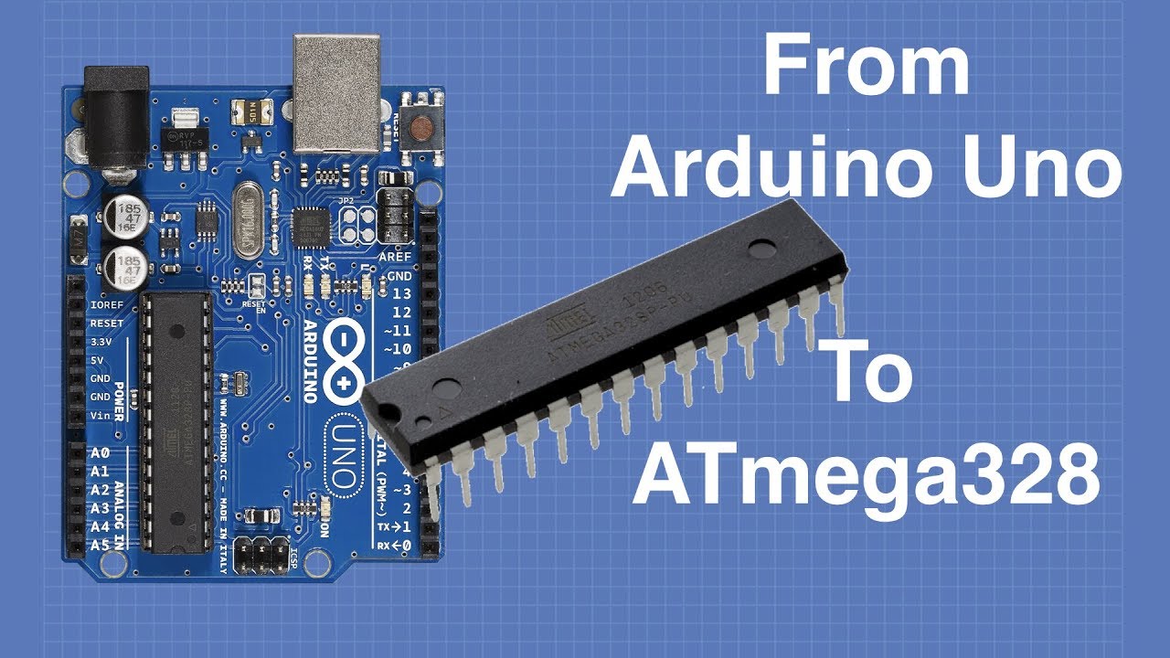
Full article at https://dbot.ws/atmega328
More projects and tutorials at https://dronebotworkshop.com
Help me to help you! Sign up for my newsletter at https://dbot.ws/dbnews
Star Wars music sketch on GitHub - https://gist.github.com/nicksort/4736535
In this final episode of ...
And i added ftdi as an external tool like this
north stream
I think that approach does use a bootloader
pine bramble
@main olive
Looked to me like it might do what you expected:
void loop() {
  serialData = Serial.readString();
  if(serialData == "HIGH")
  {
    digitalWrite(port, HIGH);
  }
}
Haven't worked much with String type at all, so just a guess.
Somebody types "HIGH" at their terminal, the Arduino reads this input, and sets a GPIO pin logic level, accordingly.
I usually create a bit more of a parser than that, but the idea is similar.
Shattuck's Forth-Like Interpreter is my usual go-to, for a command and control loop (REPL):
https://github.com/wa1tnr/Metro-M4-Express-interpreter/blob/master/interpret_m4/interpret_m4.ino
Upstream:
Feather M0 Interpreter:
https://github.com/CharleyShattuck/Feather-M0-interpreter
It differentiates integer input from any other string, and acts accordingly (ints are placed on the stack; 'words' are interpreted to launch code snippets).
(Stack is just a global array of integers, arranged as a power of two number of array elements)
This is (exactly) where the code gets executed:
https://github.com/CharleyShattuck/Feather-M0-interpreter/blob/master/Interpreter.ino#L370
 sick estuary
I'm new to the m0, do I need external pullup/pulldown if I am adding buttons, or is all of that internal now
pine bramble
@sick estuary
    int a = 13;
    pinMode(a, INPUT_PULLUP);
gotcha, so switch to ground, low is active
north stream
The M0 even offers internal pull-downs as well. https://learn.adafruit.com/adafruit-trinket-m0-circuitpython-arduino
sick estuary
Oh wow an M0 trinket
that's adorable
Yeah I realized I had an itsybitsy m0 lying around that had enough gpio to eliminate an i2c io extender I was using, should be fun
eliminating a whole IC like that is great
pine bramble
;)
sick estuary
it looks like this micro requires pretty minimal passives and comes in a hand solderable package too, wow, whats not to like
pine bramble
Those Winbond SPI flashROMs come in PDIP so that's got me thinking.
 grand basin
can anybody recommend a tutorial for programming midi on arduino for the absolute beginner?
obtuse spruce
I don't know a tutorial... But I'd be happy to point you in the right direction. What do you want to do, and what board do you have?
grand basin
Thank you! I have a teensy 4.1. I have 16 10k pots which will connect directly to the analog inputs (no multiplexing for now), and an adafruit Trellis which are intended to send single note messages (instead off latching)
If it helps, I'm hardwiring it to an axoloti DSP board. I have most of the hardware covered, but the software is entirely alien to me.
obtuse spruce
ok - how are you going from the teensy to the axoloti? Serial?
grand basin
Yes, with UART
grand basin
yup! got that one down
obtuse spruce
okay then - so what do you need next?
grand basin
So I'm opening a new sketch and making sure that it's set to midi
#include <midi.h>
and now I need to define the pots?
for reference, I understand how midi works from the perspective of a musician, so it's not a complete mystery, I just am very new to programming
obtuse spruce
Okay - let's do one pot to one CC:
const int thePot = A2; // or what ever pin you have it connected to
uint32_t lastPotValue = 0;


void setup() {
  pinMode(thePot, INPUT);
  Serial.begin(115200);
}

void loop() {
  uint32_t potValue = analogRead(thePot):
  if (potValue != lastPotValue) {
    uint8_t ccValue = potValue / 8;  // scale it to CC range
    MIDI.sendControlChange(1, ccValue, 0);  // CC#, CC value, channel
    lastPotValue = potValue;
    delay(100): // wait a 1/10th of a second
  }
}
read through that and ask questions until you're sure what every line does.
grand basin
Amazing! Okay, just a moment while I look this over
Need help understanding:
- uint32_t... //if I had 3 pots, would lastpotvalue = 2?
- serial.begin... Is this the midi bit rate (that's the wrong word, I'm sure)
obtuse spruce
No - lastPotvalue is the last value we read from the pot -- you only want to send a CC if the value changes.
grand basin
understood
obtuse spruce
Serial.begin() is the rate of the serial port to your debugging console - usually over USB... bit still has a "baud"... generally matches your debug window in the IDE.
(Note: This code just came off my finger tips, and I don't have a teensy with a pot here in front of me.... so I'll probably tweak it a zillion times as we go along...)
don't try to generalize this code right now - get it working - in your head, then on the board, for one pot first.
grand basin
okay, thank you. My one last question at this point is, I've seen a lotof people lay out the pot like this:
Pot PO1(A9, 0, 20, 1)
but don't see it in your code. Are these just two different ways of doing it?
obtuse spruce
Well - that is using some Pot object from a library that provides it. I don't know what library that is....
So, I'm just showing you the "down and direct" was of doing it - which might be better for learning.
If I had to guess from the code Pot PO1(A9, 0, 20, 1) I'd imagine that the library is creating an object that manages reading on pin A9, and scales the readings from the hardware (0 to 1023) to the range 0 to 20, with granularity of 1.... but I'm guessing... and really, we're just doing something similar in the code above explicitly (save the granularity bit)
grand basin
oh I'm sorry, it's pin, control message, cc, and channel number
didn't realize different library = reads a lot differently 😄
obtuse spruce
OH _ well then, they are using one of those librarys that implement most of a control surface, and all you do is define the positions of the inputs.
That is a perfectly fine way to go... though it amounts to mostly "configuration in code" - It will do alot, and perhaps just what you want, but you won't get into the grit of coding your own controller.
Do you know which library that code example comes from?
grand basin
I believe it's the fortyseveneffects midi library
I've seen it referenced all over the place with respects to arduino and midi.
So the code that you made is more direct. I'm okay with that
obtuse spruce
That's just the library you're using when you write MIDI.sendControlChange -- it deals in MIDI messages, not devices like pots.
And - to be clear, the code I gave is using that library!
grand basin
Okay. Wow my total beginnerness is showing
so I put your code in and got this message
obtuse spruce
statements end in semicolons in C++ --- I mistyped!
grand basin
no problem 🙂
obtuse spruce
I probably mistyped alot! I type fast and sloppy in Discord! 😄
grand basin
I've seen this error on other codes that didn't work when uploading
is this because I did the #include <midi.h> at the top?
obtuse spruce
oops, My bad... we need to create a MIDI object..... which the MIDI library does with a somewhat odd, unusual line of code:
After the #include line, add:
MIDI_CREATE_INSTANCE(HardwareSerial, Serial1, MIDI);
That doesn't look like the declaration of a global object named MIDI - but it is... because the midi.h library you #included defines MIDI_CREATE_INSTANCE to be a macro - meaning a thing that expands out at compile time to some actually legal C++ code that does do the declaration.
grand basin
Oh I got it. So the library is set up but you have to make the declaration too
Serial1 is not declared in this scope
obtuse spruce
All the include file does is add the declarations of types, classes, functions, constants, and sometimes global variables, to your program. Every thing you reference in a C++ program must be declared somewhere - when you say analogRead(....) something has to tell the compiler what is this analogRead you speak of? Those delcarations are in header files, which are included via #include. There is one massive include called #include <Arduino.h> which brings in the declarations of 100s of useful things. You should include that line before your include of MIDI.h... you only don't have to because MIDI.h did it as well (it needed those things declared, too!)
If you find and look at the actual file, MIDI.h (and I suggest you do) - you'll see that it declares a class called MidiInterface with many functions you can call on it, like sendControlChange, sendNoteOn and others. The funny line I had you include declares a global object, named MIDI that is of the type MidiInterface - and so you can call any of those functions on it... like the code does with MIDI.sendControlChange(1, ccValue, 0);
(hope this is helping.... or if you already know this much....)
grand basin
Okay great that illuminates a lot. I need to understand reading libraries better. I've tried to poke around the midi library but I can't make heads or tails of it yet. With this knowledge it makes more sense.
Not sure why "serial1" was not declared
obtuse spruce
It doesn't help that the MIDI library is written in a somewhat complex pattern in order to efficiently support MIDI over serial lines, MIDI over USB, and MIDI over bluetooth ... all of which are somewhat different their needs.
grand basin
and MacMIDI
obtuse spruce
Serial1 was declared! In Arduino.h
grand basin
obtuse spruce
Ah - well, 1) try adding #include <Arduino.h> to the top of the file... .but more importantly, have you choosen your board in the IDE?
Different boards have different numbers of serial ports - and the IDE arranges (magically) to have the Arduino.h header (and headers it includes) declare just exactly the serial objects that the chosen board has.
grand basin
d'oh!
Hey it worked! I need to see if the pot is working now
well, I've encountered a plethora of problems, only some of which involve the teensy
obtuse spruce
Whee... I'd suggest running the MIDI into your computer first, and using a MIDI monitor program to see what it does
grand basin
Strange. Neither the computer nor ableton can locate the device
obtuse spruce
ah - wait, you don't have DIN MIDI from the teensy to the computer, do you?
You're expecting USB MIDI to work here?
grand basin
Currently usb midi
I was previously trying to run DIN into the axoloti via the UART pins, but things went a little haywire so I decided to do USB midi instead
obtuse spruce
Then we need to change the declaration of MIDI to get USB
grand basin
MIDI_CREATE_INSTANCE(HardwareSerial, Serial1, USBMIDI); ?
obtuse spruce
Nope - the last word there just becomes the name of what you are declaring.
We need something different for the first two....
BUT - it seems Teensy doesn't play by the normal rules here.
grand basin
I've gotten the USB midi to work before using a specific sketch for a controller I don't have the hardware for. I can check there.
obtuse spruce
- comment out the line:
// MIDI_CREATE_INSTANCE(HardwareSerial, Serial1, USBMIDI);
- change this line that sends the CC to:
usbMIDI.sendControlChange(1, ccValue, 0); // CC#, CC value, channel
- in the IDE menus: Tools > USB Type > MIDI
grand basin
that's the step I was missing!
obtuse spruce
that will change the USB port to, on start up, announce a MIDI interface to the computer --- and it will arrange to declare usbMIDI in the Arduino.h include
grand basin
Got ableton to recognize the device, but the pot doesn't work. I'm going to try one or two more things then probably take a break because this project has my head buzzing!
I changed to the correct pin on the Teensy
pine bramble
don't forget to drink lots of water
obtuse spruce
You can insert debugging over Serial: Serial.print("read pot at "); Serial.println(potValue);
grand basin
thank you haha
pine bramble
;)
grand basin
where in the code is that placed, and where would I see the results of that?
obtuse spruce
well - I'd put it right after the line where the pot was read.... do you see it?
on a line before the if....
grand basin
Yup, put it in, it worked. What should I look for after uploading that?
obtuse spruce
well... you should see the values being printed on your debugging console in the IDE
lots of them!
grand basin
if it's at the bottom where the error are, I'm getting nothing so I'm guessing there's a hardware issue
obtuse spruce
no - it is a separate window you need to open
grand basin
oops
obtuse spruce
Tools > Serial Monitor
grand basin
Board at usb:14410000 is not available
obtuse spruce
hrm.... I wonder if Teensy cannot be both a USB MIDI and a USB Serial device at the same time?
This I don't know....
grand basin
looks like I'll have to turn to the teensy forum for this one.
well hey, I want to thank you so much. This project has been a series of 'bashing my head against problems until I break through', so I will succeed 😄
I didn't know what UART, i2c, or really what a capacitor was a month ago, so onward and upward
obtuse spruce
most welcome - hope we'll do more and get you further another day
 rotund loom
Hello guys, I just started playing with my new Feather M4 last night and for some reason everytime I plug it it it show as USB not recognizable. I tryed everything I could find on the adafruit website and github page. The bootloader works fine and I can load some arduino code on it and it works, but when I reset it or unplug and replug it, it just wont recognized it as a USB device. any idea whats going on ?
I had circuit python installed at first and I tryed some arduino scripts and since then its like that
and also the CHG led is flashing rapidly, which was not the case before all this started to happen
obtuse spruce
If you want it back as Circuit Python, you'll need to reload it. Loading an Arduino sketch overwrites CP
If you just want it to mount as a UF2 device... You need to click reset twice quickly
magic field
how many software serials are possible ?
obtuse spruce
I bet there's not fixed answer to that. It probably depends not only which dev board you are using, but also on how much you are using those serial connections.
pine bramble
I have never seen a Serial2.begin(9600); anywhere. ;)
I don't remember what a software serial is, exactly.
magic field
it's a not-hardware UART
pine bramble
magic field
those suck; they only do 1 rx at a time
pine bramble
I think the thing to notice is that it uses interrupts.
Beginners aren't going to get it right, anyway.
Once a person realizes how hard it is to do certain things, they stop wanting to get them done (if they're both unmotivated and rational ;)
Others drink a stimulating beverage, roll up their sleeves, and maybe take the phone off the hook.
vivid rock
What about this library?
https://www.pjrc.com/teensy/td_libs_AltSoftSerial.html
magic field
it doesn't mention running more than 1
pine bramble
In eForth (on STM32F407 Discovery) I just wrote to the registers to setup a second USART .. and it just works for writing to the Lumex 96x8 display (which uses a USART at 115200 bps).
Based on that I would say listening is a lot harder to implement. ;)
vivid rock
@magic field yeah, looks like it... so maybe the easiest choice would be just getting a board with several hardware serial peripherals. SAMD21 can support 4, IIRC
magic field
4 pfft! i want like 20
vivid rock
get 5 boards 🙂
magic field
:p
pine bramble
vivid rock
seriously, it is hard to imagine doing 20 UARTs in software at any decent speed
pine bramble
Looks like I wrote to the data register and then checked the status register to see that the byte got sent out the USART port pin.
So it's not very robust but it works because eForth does everything sequentially.
Yeah this is motivating me to get an SPI handler done in eForth.
I think i2c would be harder.
Could probably do something nice with shift registers along the same lines.
Set 'em high-Z to multiplex.
vivid rock
Take a look at this: https://atlas-scientific.com/ezo-accessories/81-serial-port-expander/

Atlas Scientific
Expand a single UART (RX/TX) serial port into 8 additional serial ports with Atlas Scientific’s 8:1 Serial Port Expander
pine bramble
Looks nice. ;)
Then you probably just add some addressing info, maybe in ASCII, to your data stream. ;)
vivid rock
never used myself - got to it after series of links... but sounds like a nice idea
there are plenty of i2c multiplexers, so why nto uart, too?
pine bramble
What's the pricing on those, and is it aging tech or are they active?
pine bramble
You get to love it and then find out you bought the last one and they're not restocking .. ever. ;)
I managed to write a master transmitter i2c handler for C8051F330D (a Silabs MCU) like 18 years ago .. in Forth .. from an Appnote written in C (by Silabs).
I don't think I could do it again. ;)
vivid rock
wow
pine bramble
Well their datasheet was truly a work of art.
I wanted to do the other three cases while I had all those facts in my head. Slave transmitter, Master receiver, Slave receiver.
Either the code is lost (today) or I found it (again) and lost it (again). ;)
I should find it because I'll probably never do one again, if I don't find it.
I used it to talk to PCF8574 (i2c port expander) and the test case was to talk to HD44780 I cant remember the character display chip number through the PCF8574.
vivid rock
18 years ago I didn't know what i2c is 🙂
pine bramble
About three years before that, neither did I.
Even after writing the interrupt-handling driver, I still don't really know that much about it.
vivid rock
I only discovered electronics as a hobby for myself 8 years ago or so
pine bramble
That's a decent amount of time. You're asking few or no really ______ questions.
vivid rock
🙂
I have some experience with robotics - FTC competition for HS students; since it is high school, there are very few people around who knew what it was 8 years ago - students from that time have graduated and moved on
so whenever I mention one of those old competitions, I sometimes get the reaction "that's ancient history, from the time of myths and dinosaurs"
pine bramble
I have a friend who's pathologically dismissive. He'll just 'off the shelf' anything you said you built, to dismiss it.
That's just a personality trait, habit, character defect.
Factor it out the same way you comment out redundant code, as there is no information contained in it, whatsoever. ;)
Information .. is a measure of surprise. --James Gleick
pine bramble
ciao
 silent oriole
Has anyone done i2c with the adafruit circuit playground express?
pine bramble
@silent oriole I must have. ;)
Yeah, probably for FRAM. That's the only i2c device I remember using, at the moment.
silent oriole
nice! I am fairly new to this but, am I sapost to use Wire.h or is there a different library I can use along side the Adafruit_CircuitPlayground.h library?
pine bramble
I don't remember. ;) Easiest way is to go ahead and use it, then comment out the include and see what happens.
I do not think I used the Adafruit_CircuitPlayground.h lib ever.
silent oriole
alright, you think I can adapt some sketches meant for the r6 boards?
pine bramble
What's an R6
silent oriole
sorry I ment r3
pine bramble
Are you thinking of the Uno, R3?
silent oriole
yup
pine bramble
Generally, the CPX is an upgrade from the Uno.
It can do more things.
Altho Uno probably has more GPIO pins.
I've never run an Uno (I started way after they hit the market).
Every lib has an examples directory.
silent oriole
found one, I am going to try it out
pine bramble
https://learn.adafruit.com/adafruit-i2c-fram-breakout/wiring-and-test
That's the 'learn' page for my Fram i2c breakout.
This is the corresponding lib repository:
It includes both Wire.h as well as the lib's header.
silent oriole
I am going to check that out then, thanks
pine bramble
So that's why I don't have to remember specifics.
I just look up the code on github, find the examples directory, and take a quick look at the top 50 lines of code in the .ino file there.
That same pattern will work for many i2c devices. Same strategy.
There will be other libs used for specific peripherals.
pine bramble
Sort-of. The CPX wouldn't be a master anymore. It'd be a slave.
I really don't know how well developed the four roles are (master transmitter, master receiver, slave transmitter, slave receiver).
master means it controls the conversation. It leads the conversation.
silent oriole
yup
pine bramble
Transmitter means it provides information. Receiver means it listens for information provided by someone else.
If it's been developed there is probably a sample project already published.
silent oriole
I see, that helps me with my search then
pine bramble
Hard to know in advance how they'll talk about it. ;)
"Circuit Playground Express slave" or "CPX slave" might get hits.
It's a SAMD21 and that might get a hit.
ATSAMD21G18A I think.
pine bramble
;)
The 'AT' part is kind of showing off; not many places utilize it.
iirc, the Trinket M0 and Gemma M0 are SAMD21E18A and all the other SAMD21 targets are SAMD21G18A (as far as Adafruit boards go).
also 'blm badge' and 'pirkey' use E18A.
silent oriole
So far I have only found this CP github issue about using adafruit boards as i2c slave (https://github.com/adafruit/circuitpython/issues/437)
pine bramble
If they implemented it that long ago, it's probably in the Arduino stuff by now. ;) Maybe it always was.
You'd have to experiment; I'm just reading code and that's not always going to give the 'right' answer.
pine bramble
Yeah I know where a lot of stuff is, even if I don't quite know how to use it. ;)
Gotta catch some Zzz's. Nice to meet ya.
silent oriole
Same nis, have a good night
pine bramble
::: up up and away! :::
pine bramble
I stepped on an IC socket that had made it to the floor. A memorable experience.
woven mica
Probably worse than stepping on Lego 🙃
pine bramble
Thumb used to take more than its share of non-fun, too.
Till I hit my late teens, the soldering iron wasn't respected enough, either. ;)
I still have a scar from an x-acto knife that wasn't stored correctly. ;)
 quartz furnace
Ouch!
pine bramble
Im using a Uno and some older Neopixels, I use the example code for testing, I change the amount of pixels according to how many iu had on the strip, upload. plug in my 3 pixels and then pop All 3 pixels dead, so i replace them change the code to 2 (I removed 1 and replaced 2) and pop again
 viral shuttle
Hi, has anyone here built and arduino drone or would know how to go about making one?
 cedar mountain
@pine bramble No type of code could do that, so you probably have a wiring error.
 reef ravine
@viral shuttle http://www.brokking.net/ymfc-al_main.html
Project YMFC-AL - The Arduino auto-level quadcopter - Home.
pine bramble
NeoPixels can handle either 3.3 Volts or 5.0 Volts, and should match the MCU's logic level voltage.
If the Uno is 5 volts throughout, then use 5 volts for the NeoPixel's power leads.
I think the Uno can be reconfigured as 3.3 or 5.0 volts GPIO. I don't remember.
(but don't mix the two)
Put in a 500 ohm resistor (470 is fine) inline with the singleton data pin of a NeoPixel (between the GPIO pin and the NeoPixel).
 shrewd wyvern
Hi guys
Anyone knows how to check for memory leaks in Arduino code
Ok different question, maybe easier
RAM: [======== ] 84.7% (used 1734 bytes from 2048 bytes)
Flash: [========= ] 87.4% (used 28178 bytes from 32256 bytes)
Do you guys think that I am running to close to the memory limits?
My issue is that I am running arduinoJson library, if I use DynamicJsonDocument it works for like 2 or 3 iterations of the function loop() if I use StaticJsonDocument it hangs in the setup() probably trying to init the ethernet shield
Maybe I am asking to much from the microcontroller
north stream
I think both ArduinoJson and ethernet use a lot of memory, so that could be an issue
shrewd wyvern
I guess the ethernet use some dynamic allocations?
(on top of that I have an LCD and I am publishing mqtt messages)
going full IOT
:p
north stream
I suspect you're right on all of those
There are plenty of more capable CPUs available that you can program with the Arduino framework.
shrewd wyvern
and all of them work alone.. like I have tested mqtt, LCD also a DHT sensor ...
all that now I decided to add the json library and struggling
yep but I had some constrains... and the project started by just reading an analogue value and control two relays to provide system state if the system is in normal, warning or alarm mode
like a simple hysteresis
I got carried away :x
just to take a bit more of your time do you know if the pubsubclient library have dynamic allocations?
I am afraid if I am able to solve this for now when I put the system in the wild I will get to the limits of the memory
after like 1 week or so
north stream
I don't really know offhand. But for all the parts you describe, the easy way forward is a CPU with more resources. However, you're wise to look out for memory leak type issues, which can show up after something has been running for a while. I built a water heater temperature profiler that logged data to an SD card and left it running for several weeks. Happily, it ran just fine and didn't run out of memory and fail.
shrewd wyvern
I don't think my code have issues I am afraid the libraries I am using start allocating more memory
example when you try to publish and broker is not available... some libraries will keep that message until it becomes available (mostly if you use QOS=1) not sure if it is the same with this library
north stream
I've been known to modify libraries to get them to just use a fixed block of memory.
shrewd wyvern
Hm ok I was able to make it work (while I was writing here)
So I changed to static allocation
but to the bare minimum I need for the json message
I have quit using an RTC and encoder to navigate on a menu..
I will try to bring that one by one to see when it breaks
and probably a good idea is to stop using floats and just multiply the scaling factor in the server
About the DHT11 sensor.. I feel that it gives 2 degree celsius more than it should do you have the same experience?
north stream
I haven't used that sensor, but I think I've seen other people describing similar issues
vivid rock
@shrewd wyvern 2K RAM and 32K flash is really quite low by today's standards - SAMD21 has 32K RAM and 256K flash; STM32, SAMD51 or nrf52840 have much more - and all are very reasonably priced
shrewd wyvern
yep I agree
and I am now used to develop for ARM with 1 gb RAM and all the storage I want .. :X
I was going all crazy with add-ons 😄
I think I am going to keep this first iteration simple
read 2 analog channels, control 2 relays, read DHT11 and MQTT publish results in JSON format to a remote broker.
I think if I can have the ATMEGA doing all that it is alright
{"a":4.511241,"b":4.667644,"t":30,"h":35,"s":"ALARM"} -> MSG number 552
vivid rock
looks like typical json
shrewd wyvern
{"a":4.051808,"b":4.061584,"t":null,"h":null,"s":"ALARM"} -> MSG number 2503
😦
I wish I could use something like valgrind to check the memory usage of my code
I almost bet if I wait 1 more hour or something other field will go null
I don't know if it is the ArduinoJson library or any other
I am using all this
#include <SPI.h>
#include <Ethernet.h>
#include <PubSubClient.h>
#include <ArduinoJson.h>
#include <LiquidCrystal_I2C.h>
#include "DHT.h"
#include <Adafruit_Sensor.h>
 stuck basin
Hi - I'm new.
I am tasked with building a multi wire cable tester, initially with 12 pairs of pins and a inline resistor to measure.
I want to check for continuity, opens/shorts etc.
I also want to expand this tester to suit other cables (as yet unspecified).
I'm going to learn to use an Arduino for this. I want an LCD and buttons too, output LED's to indicate fail/pass.
Can you please advise which Arduino to go for and what else Ill need to connect to it?
I think it's the Mega - but am unsure given the plethora of different types.
Please tag me in a reply - thank you.
 wraith current
@shrewd wyvern I've seen this too. When setting values in the json it has do a string copy and it take more memory to do that.
The thing to remember is that a StaticJson object is allocated on the stack and DynamicJson is allocated on the heap. The stack is usually much smaller than the heap and so can be overflowed quite easily. It's best to have json object created and deleted at every iteration so there is no possiblity of a memory leak.
There are also smaller/more efficient json libraries you can use; they just have less features available.
north stream
@stuck basin A stock Arduino comes close, with 19 I/O pins to play with, not quite enough for 24 wires, especially with some taken up running the UI. You could just take a step up with a Mega, or use I/O expanders, depending on whether you prefer a bigger board or an extra chip or two.
 magic needle
just typed out a whole rant asking for help, turns out the battery was low (just following a tutorial). Yeah, I know I can use the wall wart, didn't think to until just now. I didn't think the 9V was that depleted. Le GRRRRRR! I should have known better.
 icy matrix
hello friends, noob here, i need to push a grbl update to an atmega 328p via the arduino ide. If I choose "Atmel Atmega 328p" as a card the upload fails with error code "not in sync: resp=0xda", if I choose Arduino Nano as a card the upload fails because the sketch is too big
can I do anything about that? thanks 🙂
north stream
Hmm, I don't know if the software is designed to occupy the whole chip, or run with a bootloader. I also don't know how you're hooking your computer to the ATmega.
icy matrix
via micro usb
north stream
I'm missing something: ATmega chips don't have USB ports. Are you loading it onto an Arduino board?
icy matrix
it worked successfully half an hour ago, then i edited config.h to edit a couple of parameters and now it doesn't anymore
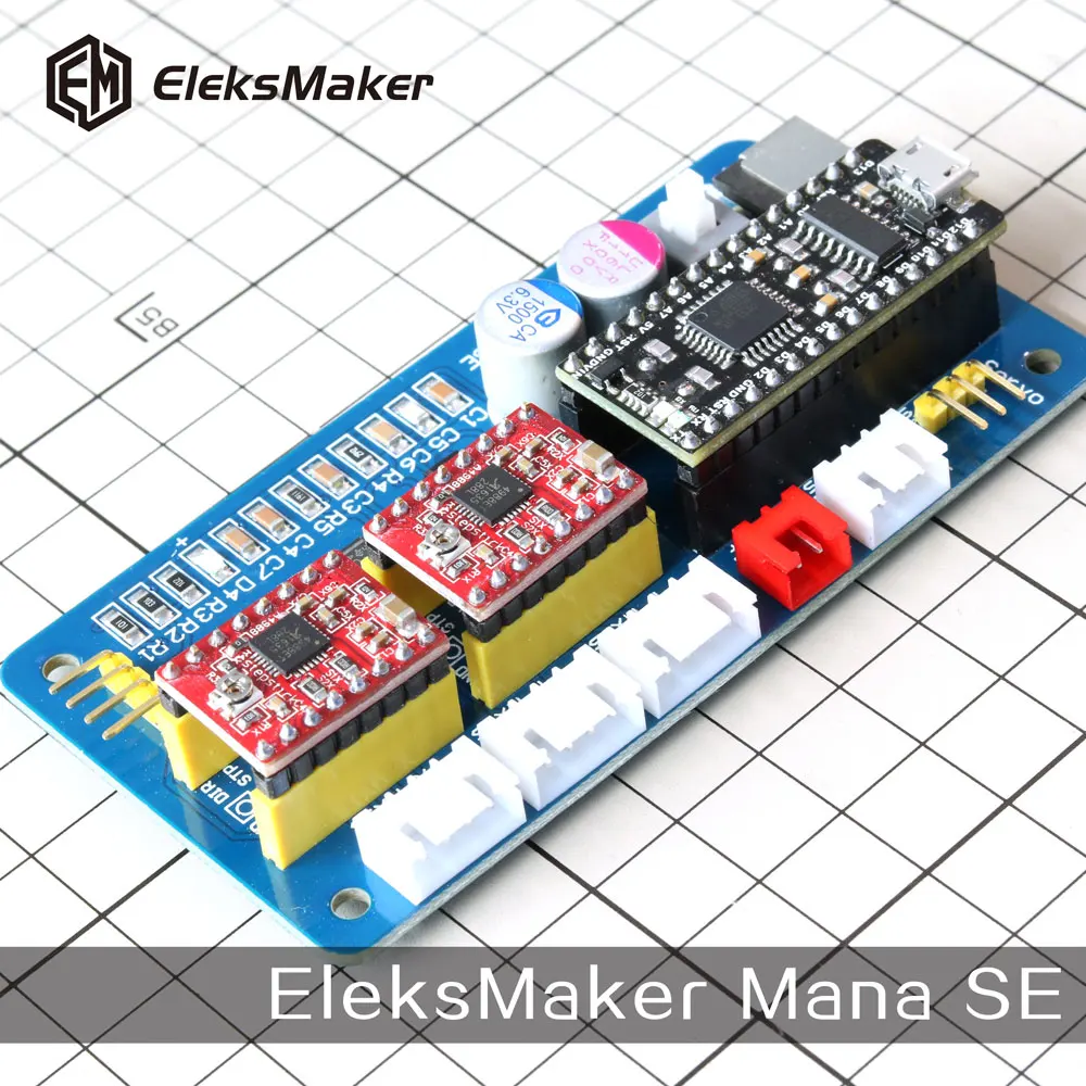
ok the board itself is a eleksmaker mana se
this one here
 north stream
That does look like a Nano. I wonder if your config changes made the software become too large to fit.
icy matrix
i just uncommented two parameters and commented two other parameters
i could remove a bunch of comments from the files
and see how it goes
north stream
Worth a try. What I'd do is put it back, build the software, and write down the sizes the IDE displays, then try making the various changes and seeing what effects they have on the size.
icy matrix
removed every single non essential comment in the whole package
still too big
i'm puzzled it even worked 45 minutes ago
north stream
That is odd. Do you have a backup of the original?
north stream
Oh, that's frustrating.
icy matrix
welp, i knew what i was getting into with a chinese clone of a clone
ok, the micro responds again
but i can't upload anything useful onto it
and it doesn't connect via com to anything but the ide
north stream
It ought to show up as a serial port.
north stream
What happens when you try to upload?
icy matrix
avrdude: stk500_recv(): programmer is not responding
avrdude: stk500_getsync() attempt 10 of 10: not in sync: resp=0x7f
i think i just uploaded garbage onto it while tinkering before
north stream
It could be you unintentionally overwrote the bootloader.
north stream
Either that or an ISP programmer.
icy matrix
would the "arduino as isp" option work from the ide?
north stream
Yes, if you have another Arduino.
However, that may not be your problem here. The messages refer to "stk500", which may not be right for your board, you may need to set the programmer type to something else.
icy matrix
well, avr isp worked fine one hour ago
time for some roulette programming
what's the harm
even though i think the bootloader is involved because the factory reset utility from eleks can't even communicate with the board
 uneven rivet
i guess I'll start here. I have an Arduino project I'm working on and I'm also pretty new to Arduino. I'm trying to make a LED simulated Plinko board (for those who may not know what a plinko board is https://www.youtube.com/watch?v=PSN-CYrtyFo). The idea is to basically, as I said, simulate a Plinko board but using only leds and 1 momentary push button. I have all the ideas of what I want it to do and how, but I'm getting stuck. The way it should work, is when the arduino is powered, an LED sequence would start and go back and forth between 5 LED's. Then, when you press the button, I want the LED sequence to stop and keep whichever LED that was last lit, on for a second or two and then continue onto the actual "Plinko" function. I can get the LED sequence to work but thei ssues start when I try to implement the button to stop the sequence and keep the last LED lit. any help would be very appreciated. Also if you guys need more info let me know. Thanks!

I bought this game on the Target app a few days ago and I was wanting to make a video about me playing this game, and here it is!
north stream
If your LED sequence is being run with delay() statements for timing, you'll likely need to re-write it so that it can check the button while waiting for the LEDs. If that's your issue, there is a useful writeup here: https://learn.adafruit.com/multi-tasking-the-arduino-part-1
If your issue is something else (like how to stop a sequence in the middle), describe where you are and where you're getting stuck, and we can try to help out.
uneven rivet
I have bneen trying to learn and understand millis() but it's a lot more confusing for newbies like myself haha
Here's a video I made of an attempt at that https://www.youtube.com/watch?v=9LAVO2CpOsM&feature=youtu.be****
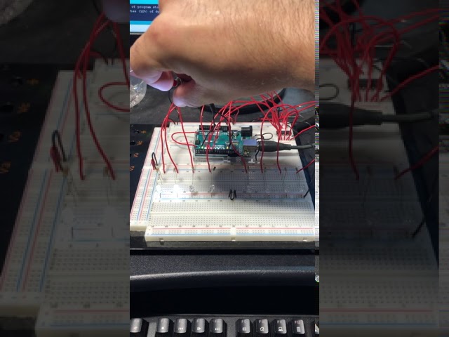
Problem with my Arduino program. The intended result is for the led sequence to stop completely when button is pushed. Instead I get a strange result.
Here's the links to the posts:
https://forum.arduino.cc/index.php?topic=699869.0
https://www.reddit.com/r/arduino/comments/i...
north stream
It is confusing, but the basic notion is each pass though the loop, ask "is it time to do the next thing?", if so, do the thing and calculate when the following thing will happen. After all that, do any button processing. Unfortunately I cannot watch videos because I am at work.
uneven rivet
So... How might that look in code? for instance if I wanted to blink an led attached to pin 2 on and off? Using millis() Instead of using delay?
north stream
The example code at https://learn.adafruit.com/multi-tasking-the-arduino-part-1/using-millis-for-timing does just that
uneven rivet
@north stream oh awesome thank you! I'll take a look at this rn
icy matrix
ok so, now that the situation with my board has escalated to almost bricked status
how do i completely reset the atmega 328 in my eleksmana se considering that i have no access to the pins?
north stream
Presumably you'd unplug the Nano from the main board to get access to the pins
 tacit plaza
I need some help or ideas for some sketch code:
What I need is to be able to send a serial value preceded with a "+" or "-" character, and the code in an Arduino R3 to use that value to go through steps in either "+" (forward direction), or "-" (reverse direction).
The steps would be a series of high and low values of four digital IO pins, using the values indicated here:
step 1 = H, L, L, L
step 2 = L, L, H, L
step 3 = L, H, L, L
step 4 = L, L, L, H
When a negative value is entered via serial, it should go through the same steps in reverse order. In both instances, whether forward or reverse, the truth table above would continuously loop, for example, if given an input of "-14", then the values should go through step 4, 3, 2, 1, then repeat two more times, and then do two more steps continuing in reversed order (14 total steps).
Code examples, better ideas, or suggestions of "best practice" to accomplish this would be greatly appreciated.
I suppose that prerequisite to this, I should probably ask if sketch code is able to take a serial string and apply the first character to the value of one variable, and anything after applied to another: "+" or "-" being the direction, and anything else being stepCount .
obtuse spruce
first thing to do is break down your problem into two independent things:
- Write a code that sets up and executes the IO. Something like a pair of functions:
void setSequence(bool backward, int count):
void runSequence();
- Write code that handles input from Serial, and converts that input into a call to
setSequence
I can dive deeper in more detail if you want.
tacit plaza
I was thinking the same, setting up the sequence as a user defined function, I'm just new to sketch code, and wondering about what some best practices would be to approach this. There is no rush.
obtuse spruce
I would ignore the Serial input first - just get the sequencer to work.
enum Direction {
  forward,
  backward
};

constexpr NUMPINS = 4;
constexpr NUMSTEPS = 4;
const int steps[NUMSTEPS][NUMPINS] =
  { { HIGH, LOW, LOW, LOW },
    { LOW, LOW, HIGH, LOW },
    ... // etc...
  };

void setSequence(Direction dir, int count) {
  ... // set up global state variables here
}

void runSequence() {
  ... // see if enough millis() have elapsed and do the next step
}

void setup() {
   ... // set up pins here
   setSequence(false, 14);
}

void loop() {
  runSequence();
}
There is a skeleton. Get that to work first
tacit plaza
👍
Just guessing, but in that example, the sketch would treat "steps" as an array?
obtuse spruce
steps is an array of arrays!
The first index is the step number (0 to 3), the second is the pin position (0 to 3)
I'd probably also have:
const int pins[NUMPINS] = { D4, D2, D6, D12 };
(or whatever pins you have) -- so that you can decouple the choice of pins from the code that is doing the step sequencing. Think of it this way: The seqeuncer only cares about "I want to set the four outputs to this .... now" - it doesn't really need to be concierned with the particulars of the pin number
tacit plaza
OR it could be treated as a 4 bit binary, but with only 4 valid values... 1000, 0010, 0100, and 0001. IF that might simplify, but then would need to parse and translate back to L or H for each pin again, in order to use.
obtuse spruce
No - that would make your code harder, more complex, more chance for coding error --- and for no reason other than to be clever.
This way is direct, and very very clear.
You should only go to encodings if you had, say 10k steps you needed to encode.
tacit plaza
Wasn't sure which would be more efficient, translated to binary, or array within array. In a more familiar (to me) language such as PHP, a simple 1 line function to grep() 1st, 2nd, 3rd, and 4th character would be simpler.
obtuse spruce
😁 Please forget most of the tricks you learned with PHP!
tacit plaza
No kidding. Biggest hinderance to learning a language, is the habits from previous languages.
obtuse spruce
Remember, you have a massively powerful compiler here - and in most sketches (like this) there is very little computation going on, relative to the power of the device you are running it on. As a rule, go for the clearest, simplest code you can -- far more important to make the coding now (and in 4 months when you look at it again) likely to "just work" -- optomize only after you know you are using too much memory or time.
So we make the code express your problem --- and your problem has nothing to do with figuring out how to tightly pack bits!
tacit plaza
Right. Sometimes I just also think of it as being "mentally efficient" if an array can be simplified. Easier to remember the elements, without thinking about them in two steps.
obtuse spruce
I look at it this way: There are two dimensions to this problem: The dimensino of step - and the dimension of output number.
Try writing this function (which you'll need):
void outputStep(int step) {
  ...
}
You'll see that the double array makes this function almost trivial.
as it should be!
tacit plaza
I think that for me, it's just difficult to visualize how it would take a (sometimes) relatively large number of steps and interpret that into the cycle of individual, defined steps, for example, moving a stepper motor 300+ steps for a CNC axis. I know there are libraries to handle that, but they would not be basic enough for me to demonstrate to young students in a way that should be reasonably easy for them to understand.
obtuse spruce
I guess I'm not following here... Assuming that these four steps are what moves that motor - then the skeleton above could easily do this - there are still just 4 rows in the array -
should I flesh out setSequence and runSequence some more?
tacit plaza
May not be necessary at this time... but may I ask for some clarification (via comments) on what each part should do/accomplish, to make sure I'm on the same page?
obtuse spruce
sure
Here's how I'd break this part down
void setupPins() {
  // set up the pin hardware using pinMode()
}
void outputStep(int step) {
  // set the output of each pin based on the selected step
}
void setupSeqeunce(Direction dir, int count) {
  // prepare global variables for playing count steps in the given direction
}
void runSequence() {
  // if count steps completed, just return
  // if enough time has elapsed since the last time this was called
  //    go to the next step (respecting direction, and cycling around the NUMSTEPS
  //    output the steps
}
you will need some global variables that setupSequence and runSequence use to reset and keep track of where the system is in the output seqeunce..
does that make it more clear?
tacit plaza
Yes. Thanks.
obtuse spruce
One last thought: See if you can make the C++ code so simple and clear, that the comments are redundant and can be removed.
tacit plaza
I mainly just need them for place holders at the moment, because my time is so split up by my schedule and available time.
Once I get it figured out and working, I'll likely expand on it to feedback human readable "currentXpos", "currentYpos", and then also incorporate a Feed Rate (important to actual linear motion control and CNC.
This is all sort of a middle project I am trying to develop for students. Instead of using a hat/shield and libraries, something that better serves to show how stepper motors and robotics work in better detail... And this follows a bi-weekly "Scavenger Hunt" that we do as a class, where we take a bunch of donated, broken or obsolete electronics and scrap computers, and they go through to see what components or parts can be salvaged, tested, identified, etc, for points, and then at times put parts to use. Last week we had a bunch of common 4 pin stepper motors from old CD-Rom drives and DVD players. So now the kids want to learn how they work and what they can use them for.
 rich lodge
How could I read the "1" that im sending in the serial monitor and make it do something like in this pic?
That bottom if statement wont return anything
north stream
What's the other end of the serial link connected to? Is it sending anything?
rich lodge
Yeah its sending, I have unity picking it up to move a cube. I cant seem to get read to work in the actual IDE itself though
I just have this in unity
   {
      transform.Translate(Vector3.right * Time.deltaTime * 15);
   }
   if (sp.ReadByte() == 2)
   {
      transform.Translate(Vector3.left * Time.deltaTime * 15);
}```Since you've got something else occupying the serial link, printf debugging is tricky, but you could do blink debugging.
obtuse spruce
@rich lodge - is your question "how do I get Unity on my computer to read the serial communication that is normally displayed in my IDE serial console window?"
rich lodge
No, unity really is not related to my question (as far as I know). What im asking is, how do I get an if statement to trigger in the arduino IDE when the serial monitor reads 1?
@obtuse spruce
obtuse spruce
OH - you want to know in the Arduino when the other side has completed the read?
vivid rock
serial communication is between two units
usually, one unit is the arduino, the other, your computer
arduino sends something, computer reads it
or the other way around
obtuse spruce
Perhaps it would help if you describe what the system is supposed to do --
But - the very very short answer is: You can't know in the sending side (the Arduino) when the receiving side (the serial monitor, or unity, or what ever) - has actually read the value. With the standard classes, you can't even tell if the UART (or USB) has finished sending the value.
The normal way to design a system where the sender needs to know that the reader has in fact read it... is to have the reader send some confirmation data back to the sender.
rich lodge
So when I press a button on my bread board, I have it write "1" to the serial monitor, then I want an if statement to return true if it reads "1". I have this working between the arduino IDE and Unity, but I want it to write and read inside the IDE. I just dont know how I would do that or if its even possible
Arduino IDE:if (digitalRead(butPin1) == LOW){ Serial.write(1); delay(2.5); } Unity:
   {
      transform.Translate(Vector3.right * Time.deltaTime * 15);
}```Oh - so in Unity - you have it writing 1 back after it has read the value?
And you're asking how to do that from the IDE's serial monitor?
rich lodge
Yeah, so instead of doing that in Unity i want to that in the IDE
obtuse spruce
There is a type in field at the top of the serial monitor window in the Arduino IDE - where you can type something and click "SEND" -which will send it back!
vivid rock
why do you need serial monitor at all?
it seems that all you are looking for is sending data form one part of arduino script to another
this is much easier done by setting a value to a global variable and reading it, or using interrupts
rich lodge
Yeah of course, but this more of a test to see how all the writing reading stuff works
obtuse spruce
BUT - you can't send a numeric 1 (that is, a byte of value 1) - because it is a text field - you'll be sending a '1' character, ( value 0x31, or 49) -
So - just make your code accept either - and you can the debug in the IDE Serial monitor --- which is what I gather you are trying to do
rich lodge
Okay, ill see what I can do. Thanks guys
obtuse spruce
int b = Serial.read();
if (b == 1 || b == '1') {
  ...
}
 silver acorn
Anyone know if any powerful IR sensors to use with Arduino that can sense 2-5 inches above a surface?
silver acorn
What was that number VLC?
cedar mountain
The VL6180X (sometimes called the VL6180) is a Time of Flight distance sensor like no other you've used! The sensor contains a very tiny laser source, and a matching sensor. The VL6180X ...
Or the simpler https://www.adafruit.com/product/466

The VCNL4010 sensor is a nice way to add a small-distance proximity sensor to your microcontroller project. For longer distances (in the range of cm, you can use a SHARP IR distance sensor, ...
tacit plaza
What function(s) and syntax would be needed to break a text string from serial into two parts, using the first character as a string value, and the remainder (of undetermined length) changed to an integer for another variable's value?
For example, if "+138" is sent, have the Arduino sketch use it as:
direction = "+" ;
steps = 138 ;
Would it be something like (just guessing)...
direction = mySerial.substring(0, 1) ;
steps = toint(mySerial.substring(1)) ;
Or am I completely off base?
magic field
Base 10 sucks. But.. id just do it byte by byte.. every digit arriving , multiple your result by 10 and add the current digit value.
obtuse spruce
well, first off -- do you have a char * or a String?
tacit plaza
No idea. If I type "+138" into the serial monitor and send, then which would it be on the Rx end?
(without the quotes)
obtuse spruce
It depends on which function you use to read it in the Arduino side
Let's say you use Serial.readString()
Then you have a String object. String is a class which is part of the standard Arduino Wiring core library. It is pretty easy to use.
tacit plaza
Right. And it would need to be a string in order to use string functions.
obtuse spruce
String userInput = Serial.readString();
char dirChar = userInput[0];
int stepCount = userInput.substring(1).toInt();
Those are String member functions. There is a whole other set of "string" functions, based on char * named things like strlen, strcpy, etc....
I think, if you are a) developing for students, and b) are not processing tons of text every millisecond.... stick with String - it is much easier to use, and much safer.
"... are not processing ..."
tacit plaza
...and more familiar.
obtuse spruce
The defintion of the String class is in WString.h if you want to see what it has to offer.
nimble cobalt
When using an M0 Express with Arduino, how do I identify the SCL/SDA pins as a digital input?
pine bramble
So, just wondering what this extra memory usage is. This a Flora with an atmega32u4
if i switch it to arduino uno, suddenly the same sketch uses way less memory
what is this memory being used by? because to my knowledge, the 328p and the 32u4 are very similar
(oh and compiling for the feather 328p gives the exact same memory usage as the arduino uno)
so this narrows it down to 32u4-specific code
cedar mountain
I don't know for sure, but possibly it's because the 32u4 uses native USB for its serial connection, whereas the Uno has an external chip for it and just has an easier UART connection. So maybe its that driver.
pine bramble
and I'm assuming that there's no way to get a smaller version of the driver (or possibly remove it)
cedar mountain
Couldn't say, as I'm just guessing to start with.
pine bramble
alright, thanks for the help
obtuse spruce
@nimble cobalt - I believe the Adafruilt pinout diagram for M0 Express is wrong... it says those pins can be used as digital pins 21 and 20... but that won't work. Reading through the core files.... you can just use:
pinMode(PIN_WIRE_SDA, INPUT);
pinMode(PIN_WIRE_SCL, INPUT);
    // or INPUT_PULLUP or INPUT_PULLDOWN as needed
...
int sda = digitalRead(PIN_WIRE_SDA);
int scl = digitalRead(PIN_WIRE_SCL);
 deep hazel
anyone here have experience with the Adafruit SI4713 fm transmitter library? i'm trying to adjust the line level input limit, the default in the header file says it's set to 636mV but i'm trying to get it so it plays nicer with an output that uses 2v line out
setting SI4713_PROP_TX_LINE_LEVEL_INPUT_LEVEL to 2000 doesn't seem to set it to 2000mV, that or it just doesn't work how i'm assuming it does
north stream
@deep hazel It's a little more intricate than that. If you look at the chip programming guide http://www.adafruit.com/datasheets/SiLabs Programming guide AN332.pdf, under "Property 0x2104. TX_LINE_INPUT_LEVEL" on page 38, you'll see that the register isn't just a number of millivolts, it's a bitfield that sets both an attenuator resistance and a maximum deviation level. It looks like 636mV is the maximum supported level (the bitfield is only 10 bits, so it can only accommodate numbers up to 1023). However, you can use series resistors along with the built-in attenuator to divide your 2000mV input signal down to 636mV.
icy matrix
for those interested, here's the followup to the plottergeist chronicles and the hexed 328p that didn't want to update to grbl1.11 and is now lowkey bricked
I've been trying to burn the bootloader onto the board and here's what comes out
avrdude: Version 6.3-20190619
Copyright (c) 2000-2005 Brian Dean, http://www.bdmicro.com/
Copyright (c) 2007-2014 Joerg Wunsch
     System wide configuration file is "C:\Users\web\AppData\Local\Arduino15\packages\MiniCore\hardware\avr\2.0.6/avrdude.conf"

     Using Port                    : COM5
     Using Programmer              : stk500v1
     Overriding Baud Rate          : 19200
avrdude: stk500_recv(): programmer is not responding
avrdude: stk500_getsync() attempt 1 of 10: not in sync: resp=0x03
avrdude: stk500_recv(): programmer is not responding
avrdude: stk500_getsync() attempt 2 of 10: not in sync: resp=0x03
avrdude: stk500_recv(): programmer is not responding
avrdude: stk500_getsync() attempt 3 of 10: not in sync: resp=0x03
avrdude: stk500_recv(): programmer is not responding
avrdude: stk500_getsync() attempt 4 of 10: not in sync: resp=0x03
avrdude: stk500_recv(): programmer is not responding
avrdude: stk500_getsync() attempt 5 of 10: not in sync: resp=0x03
avrdude: stk500_recv(): programmer is not responding
avrdude: stk500_getsync() attempt 6 of 10: not in sync: resp=0x03
avrdude: stk500_recv(): programmer is not responding
avrdude: stk500_getsync() attempt 7 of 10: not in sync: resp=0x03
avrdude: stk500_recv(): programmer is not responding
avrdude: stk500_getsync() attempt 8 of 10: not in sync: resp=0x03
avrdude: stk500_recv(): programmer is not responding
avrdude: stk500_getsync() attempt 9 of 10: not in sync: resp=0x03
avrdude: stk500_recv(): programmer is not responding
avrdude: stk500_getsync() attempt 10 of 10: not in sync: resp=0x03
avrdude done. Thank you.
north stream
Looks like it's trying to use the STK500 programmer protocol, and I'm guessing you don't have an STK500. What are you using to flash the bootloader? Another Arduino?
gilded swift
If you’re programming with another Arduino, you need Arduino as ISP
Or a board like the DIP UNOs that can be selected as ArduinoISP
gilded swift
So ArduinoISP only works for specific Arduino.. do you mean Arduino as ISP?
And you’ve got a 10uF capacitor between reset and ground on the programmer Arduino
 hallow torrent
guys if i wanted to pass data to an Android device through an OTG cable, how would i code the outputs. basically im trying to make a joy-con like setup and buttons should be outputting keystrokes like on pc (wasd)
woven mica
@hallow torrent you can use any board that supports USB HID and use the Keyboard library
woven mica
Neither of them support it. You can use Micro or Leonardo
woven mica
no
hallow torrent
oof. i was thinking of making a controller out of material i have. well that sucked.
icy matrix
@gilded swift yes, i meant arduino as isp
gilded swift
Gotcha, just making sure I’m understanding correctly
gilded swift
It's okay, the bootloading process could be better explained
It hit me like... a month after attempting to bootload my first arduino
I actually think that's going to be a great article for me to write on my company blog one of these days
deep hazel
@north stream thanks a ton for spotting that info, somehow in my 2am brain haze, it didn't even occur to me to actually check the datasheet for more info on that lol, i just read the comment on it that's in the header file and went all "hurr durr default is 636, must get 2000"
 somber burrow
so uh, i might have gotten an led strip off of amazon that is 12V dc to turn on and off, but i wanted to use an arduino to control the colors, is there any way to get 12 v out of an arduino
vivid rock
You would need to use some transistors or a dedicated LED driver. Check this tutorial: https://learn.adafruit.com/rgb-led-strips
 somber burrow
thnx
vivid rock
if you do not want to build your own circuit. you can buy a ready LED driver module such as this one (disclaimer: I haven't tried it): https://www.amazon.com/Acxico-Driver-Module-Shield-Arduino/dp/B0821B971L/
rich lodge
Hello, I have a question. This line :
Serial.write('1');
Will not trigger this if statement :
  if (b == 1 || b == '1')```
But going into the serial monitor and typing "1" at the top and sending will trigger the if statement. Why is this?Did you connect the TX to the RX? If not, then writing something on the serial port will not arrive at its receiving end.
rich lodge
What is the TX and RX?
uneven rivet
Ok i really need some help with my code cuz i cant for the life of me figure this out and i’m starting to get slightly aggravated... it’s probably a very easy and small thing but I’m stumped. I’m trying to use millis() instead of delay(). But specifically what i’m trying to do is when my millis var reaches 1000 i want it to go back down to zero and basically start over counting up to 1000 on repeat. And apparently it’s not as easy as writing if(“millis var” >= 1000){“millis var” = 0}
rich lodge
int x = 1000;

delay(x);

x = 1000;
could that work?
just use a world variable and use that to delay
uneven rivet
No because i’m trying to avoid delay because of the issues it causes with my overall project
rich lodge
Oh
vivid rock
you can't reset millis()
obtuse spruce
Okay, so, here's the general pattern when you want to do timing with millis()
const unsigned long thingRate = 1000;   // in ms
unsigned long thingNextTime = 0;

void updateThing() {
    unsigned long now = millis();
    if (now < thingNextTime) return;  // not yet, young padawan
    thingNextTime = now + thingRate;

    // do the thing here
}
...
void loop() {
  ...
  updateThing();
  ...
}
whoops - small fix applied
uneven rivet
I’m still pretty new to arduino plus i’m trying my hardest to teach myself for work. But I don’t understand that
....
obtuse spruce
which don't you understand? the actual three dots? That just means wheverever else code you have.... I didn't mean for you to type ... in your code.
pine bramble
@rich lodge Put a 10k ohm resistor between the Arduino TX pin and the RX pin (this is a Serial loopback in hardware; the Arduino's RX pin has no 'idea' that you're looping back, so it treats the inbound data similarly to if you were connected to a remote device).
Most people won't bother with the 10k resistor, fwiw, and just use a wire.
obtuse spruce
@uneven rivet read through what wrote and be sure you understand how it works before you go on. Ask me if there are parts of it you don't see.
rich lodge
Okay thanks, I'll look into it
uneven rivet
I’m trying
pine bramble
@obtuse spruce For Feather or Metro M0 Express, D26 and D27 should work for SDA and SCL.
uneven rivet
Idk how to specify what I don’t understand. Idk how to put it into words
pine bramble
I do like the symbols you used, and that hadn't occured to me. ;)
obtuse spruce
@pine bramble - I don't see D26 or D27 defined anywhere in the core for Feather M0 Express. Indeed it is pin 26 adn 27, but variant.h for it has only:
#define PIN_WIRE_SDA         (26u)
#define PIN_WIRE_SCL         (27u)
variant.cpp Feather M0 Express
https://github.com/adafruit/ArduinoCore-samd/blob/master/variants/feather_m0_express/variant.cpp#L70
boards.txt disambiguation, metro_m0
https://github.com/adafruit/ArduinoCore-samd/blob/master/boards.txt#L150
variant.cpp Metro M0 Express
https://github.com/adafruit/ArduinoCore-samd/blob/master/variants/metro_m0/variant.cpp#L70
https://github.com/adafruit/ArduinoCore-samd/blob/master/variants/feather_m0_express/variant.cpp#L25
enumerates them in D0, D1, D2 .. Dn order.
uneven rivet
Idk... my brain is fried and i’m getting very discouraged with trying to learn and understand this stuff. I just can’t grasp anything.
obtuse spruce
And for the record - the Feather M0 Express pins image on the Adafruit page for it has the numbers wrong.
pine bramble
Yeah it does. ;)
I use the schematic and variant.cpp as most authorative. When in doubt, I check the CircuitPython source as well.
obtuse spruce
Right - I always go back to variant.cpp for "truth"... but it doesn't define the symbols D1... etc... So you can use 26 ... but I thought the symbols PIN_WIRE_SDA etc.. would be more clear in the code
@uneven rivet -- well, if you're up for it, we'll happily help through this one line at a time
pine bramble
;) it is and is more portable.
I'm not sure exactly how we get to D1, D2 .. and friends.
But so far variant.cpp enumeration has been very useful in providing the missing ones I can't find by other means.
For example, when I hacked Cricket CPX I started with an ItsyBitsy variant.cpp as there was less collision. I typed every D1, D2 in sequence to figure it out.
uneven rivet
I think i’m just gonna give myself a break for today
obtuse spruce
okay - but don't give up - the first few code hurdles are big... but they get you far, and you'll be sailing soon.. Come back tomorrow and we'll help.
 stark bridge
I find that when people are having a hard time grasping the code for a project it's because they're getting ahead of their knowledge. They want to start on their big interesting project right away. No one wants to start with boring stuff like blinking an LED but that's where everyone needs to start. Otherwise they end up with major knowledge gaps that might never be filled.
rich lodge
Sorry lol
What would I do to make this work?
'180'
It seems like putting numbers in single quotes only works for single digit numbers.
north stream
In C (and Wiring), single quotes like '1' denote a character variable, double quotes like "123" denote a string.
stark bridge
What are you trying to do with this '180'? It depends on what you're trying to do.
rich lodge
I have an if statement like this:
int a = Serial.read();
  if (a == '180') {
    Myservo.write(180);
    Serial.println("180");
    a = 0;
  }
but that if statement only works if the number is in ' '
obtuse spruce
Actually, it doesn't work with either quotes!
something in single quotes '1' is a char, a character, which has numeric value, (in this case 49). Something in double quotes "1" is a string, the value of whic is a pointer to the memory holding those characters (or in this case, one character followed by a zero byte). Something without quotes 1 is a number, which depending on what you are doing with it can be integral or floating point, and of various sizes.
It is important in C/C++ to be aware of the "type" of each value, expression, and variable. If you are new to the concept of "type", think "what shape box does this thing fit into?"
rich lodge
I've been working with C# for a couple years now and I understand types and such, but for some reason I just dont know why this doesnt work at all. I've tried single quotes, double quotes, no quotes, and nothing works. I just dont get what "a" i recieving from the SerialPort
obtuse spruce
Serial.read() reads a single byte from the serial stream, and returns it, as an integer: If you typed the letter A into the serial console, this is encoded as the byte value 65. If you typed the digit 1... that character (the digit one) is encoded as 49....
EDIT: To be clear, that "encoding" is done in the serial console of the IDE, taking characters you type and sending the ASCII (or UTF-8) encoding of them onto the serial port
So - what is writing that serial port from the other side? The serial console in the IDE? some other electronics?
rich lodge
Im writing it from unity
        if (Input.GetKey("a"))
        {
            sp.WriteLine("2");
        }
Its in the work right now lol, I changed it to "2" just a sec ago for testing
But writing 180 doesnt work either
obtuse spruce
Well then - let's look at what is being written: That line in unit is going to write the string "2", followed by a newline. So, in bytes on the wire, that is going to be a 50 (the digit 2) and a 11 (the new line character) -- two bytes.
If you read that with Serial.read() -- it'll only read the first byte, the 50.... leaving the newline in the buffer....
You could compare that character like so: if (a == 50) ... or if (a == '2') ... those are the same exact thing
BUT - since what you are doing from Unity is writing a string, terminated by a newline.... then what you want is to be reading from that serial line with the same expectation: "Please read bytes from the serial line until a new line byte... then treat those bytes as the characters in a string, and return it to me as such"
Or, in code:
String fromUnity = Serial.readStringUntil(`\n`);
Now you have a string, as sent by Unity.... and the next question is what to do with that? Well, you can interpret the string as a decimal number:
int numberFromUnity = fromUnit.asInt();
though, you'll get 0 if the string isn't digits.
So in unity you can sp.WriteLine("42"); .... which puts three bytes on the serial line ... which you can read as a string with Serial.readStringUntil('\n');
Contrast this to writing the byte value 42 on the wire. In this case, you'd be sending just one byte across the serial line, and you'd want to read that byte, and treat it as an integer directly --- it isn't a textual encoding --- it is an 8-bit value.
In that case, you'd use byte buffer[1] = { 42 }; sp.Write(buffer, 0, 1); to write just one byte.... and use Serial.read() to read it...
 lone heart
Hi, how can I slow down the speed at which a DC motor turns for 5s without using a potentiometer?
I'm using the L293D H-bridge in my Uno
wraith current
@lone heart send a pwm signal with the analogWrite function to the h-bridge
lone heart
this is what it looks like rn
i tried
analogWrite(enableBridge1,150)
but that didnt work
hmm nvm, maybe it is slower.
wraith current
this explains it all : https://lastminuteengineers.com/l293d-dc-motor-arduino-tutorial/#pwm-for-controlling-speed
Learn about L293D DC Motor Driver IC along with PWM, H-bridge Working, Pinout, Wiring, Arduino Code for controlling speed & direction of two DC motors.
grand basin
Hello, I am trying to adapt my Adafruit Trellis (original) to send a simple midi note on/off per-button. I have some code that needs to be looked at. Am I in the right place for that?
reef ravine
@grand basin either here or #help-with-projects , can you post your code to pastebin or gist?
 ripe flint
So I have this display (https://www.adafruit.com/product/1601) and i know its made for the Pi, but can it also be used on an Arduino Mega?
 glossy onyx
hello all, i am trying to make a RGB LED rainbow design on some project. and i am super new at micro controller and all. i watch youtube and did some adafuirt learning but still have issue when trying to upload a code to my micro controller. i am using a Gemma MO and a Trink MO, i copy and edit the code to "work" with the controller i have but i am getting an error. could someone help? below is the code;
#include "FastLED.h"
#define Pin A1
#define NUM_LEDS 50
CRGBArray<NUM_LEDS> leds;
uint8_t hue[NUM_LEDS];
Void setup() {
FastLED.addLeds<NEOPIXEL, PIN>(leds, NUM_LEDS);
for (int I = 0; I <NUM_LEDS; I++) {
hue[I] = 255 / NUM_LEDS * I;
}
}
Void loop() {
for (int I = 0; I < NUM_LEDS; I++) {
leds[i] = CHSV(hue[I]++, 255, 255;
}
FastLED.show();
delay(15);
}
obtuse spruce
@glossy onyx - it would help to know what error you're getting.
glossy onyx
got that issue fix 1st error now its user error on trying to get my Gemma MO to talk to Arduino so i can push the code... now i get this issue.
obtuse spruce
is there any more to that error message? perhaps hit "Copy error messasges" and paste it here (in between three backticks: ``` on one line, then ``` after)
The error there is with compilation, not flashing it ... it looks to me
glossy onyx
here is the error i copy:
obtuse spruce
"Invalid pin specified" is the error. On a Gemma M0, you can't use A1 for the LEDs
Try A2
(and of course, adjust your build)
glossy onyx
check again error says invalid pin again
static_assert(validpin(), "Invalid pin specified");
thanks for some help. im going to rest for tonight and come back at this tomorrow.
obtuse spruce
okay - night
hallow torrent
Guys would you recommend using V-USB or a similar library with Hoodloader2 on a Mega to emulate a keyboard?
silver acorn
Anyone know of a dependable current sensor that is more reliable than the ACS712 modules? I need something that can sense trace amounts of current? Thanks!
Milliamps
woven mica
maybe INA219
woven mica
no, only DC
north stream
A current transformer might be worth looking at.
 wide merlin
Hi all, I have a question about the Huzzah32 Feather. I have placed a switch between GND and EN to power the unit on and off with a 3.7v 500mAh battery. My question is, will this actually turn the unit off or is the unit actually consuming mAs of power until you turn it back "on"?
 safe shell
@wide merlin grounding EN turns off the 3.3v regulator, which would appear to turn off the ESP32 and the USB-to-UART, but leave the LiPo charger running https://learn.adafruit.com/assets/41630 (if there is 5V present on VBUS)
obtuse spruce
The 3.3v regulator will use 0.01µA standby current when disabled. That's the "typical" value - the datasheet max is 1µA... but that seems like a large range to me, I imagine you can count on it being small.
None the less - it's going to be 57 years at worst case to depelet the battery.... Are you putting the circuit in a time vault? 😄
pine bramble
Hi im trying to send RF ID serial from arduino - database then GET the same data or any data from the database and DISPLAY. But i could not even connect my arduino to my pc. Can anyone help me? Do i need to try other application? Or do i need to buy anything?
I currently use:
Arduino Uno
UTP Cable
Ethernet shield
LCD I2C
I use php language and xampp for my database
north stream
If you can't connect to your Arduino, you may need a driver for its USB-serial chip.
 bleak steppe
Hi all, I'm looking for a tutorial to play with forth implementation for arduino but I found only very old documentation, any one having a goog link to propose ?
I am also interested on using that on esp32 ; this is more documented
north stream
@pine bramble You may be able help with this one
pine bramble
@bleak steppe There's YAFFA and YAFFA-ARM.
There's some repurposing of hardware; I run eForth on a board from Adafruit (STM32F405 Express).
Leo Brodie's Starting Forth is always recommended but will work with most Forth implementations, including a desktop PC and gforth.
This was my more advanced port of YAFFA-ARM to SAMD51:
https://github.com/wa1tnr/ainsuForth-gen-exp-m4
It's stale and may not function correctly.
Shattuck's Forth-like interpreter:
https://github.com/wa1tnr/Metro-M4-Express-interpreter/blob/master/interpret_m4/interpret_m4.ino
Brad Rodriguez' Camel Forth:
https://github.com/wa1tnr/ainsuForth-CF-samd51-forth/tree/master/src/cf/0-Distrib.d
CamelForth built in Atmel Start, for five Adafruit targets:
https://github.com/wa1tnr/CamelForth-SAMD51-SAMD21/tree/master/boards
This is Arduino IDE based and is a very good model of what Forth is all about:
https://github.com/wa1tnr/Cortex-Forth/blob/master/Cortex-Forth/Cortex-Forth.ino
(The upstream versions, where they exist, won't have my unfinished edits in them. ;)
🛩️
That last one (Shattuck's Cortex Forth) was my favorite, until I found Dr. C.H. Ting's eForth for STM32F407 Discovery, which is what I am currently using (with that board as well as with Adafruit STM32F405 Express).
Ting's eForth was written in assembler. ;)
eForth can re-image itself to (internal, MCU chip) flash, to turnkey the application, without help (just a dumb serial terminal, no dev environment, to do so).
how long will a 6600mAh battery run a Feather M0 RFM96 LoRa?
vivid rock
where did you get a 6600 mAh battery?or is it two 3300 batteries connected in parallel?
pine bramble

Need a massive battery for your project? This lithium ion pack is made of 3 balanced 2200mAh cells for a total of 6600mA capacity! The cells are connected in parallel and spot-welded to a ...
this is a thing
 shadow wharf
Hello I have a quick question regarding the Arduino IDE if anyone can help. I'm trying to edit an included library (Wire.h) but the changes aren't reflected in the actual build. Even if I break the file with misspellings the IDE compiles just fine. Does anyone know how to force compile the libraries to recompile when you upload a sketch?
pine bramble
the feather is going to act as a relay, sending messages in response to received data
@shadow wharf try editing your main sketch
maybe it only recompiles when it detects changes with your main sketch
shadow wharf
no it doesn't help
I think I've noticed that if I'm including my own written libraries I have to reboot the entire IDE for the changes to take place which is sort of annoying. Otherwise I would just write a main function that's the only thing running in .ino and use my normal C-tools for everything else
But I can't for the life of me figure out how to recompile the source code files.
pine bramble
@shadow wharf You might be able to add an #ifdef test to Wire.h, then copy it to your project directory.
If that worked correctly, it'd prefer the one in your project directory.
Arduino IDE copies your files to a temporary build directory, and builds it there.
shadow wharf
I'm still getting the same error
compiles perfectly fine
the line on the bottom is the Wire.h file copied into the sketch folder and then edited like this to make the function undefined
north stream
That's just a forward declaration and would not cause a compilation error by itself.
shadow wharf
it would if there is no endd(); function defined anywhere though?
Or does the function need to be used for that to be true
this also compiles with no errors 🙂
north stream
Yes, that shouldn't compile
stuck coral
Known issue with arduino IDE, you should try platformIO
"issue"
Its not a bug its a feature
PlatformIO has a nice "clean" button where you can just clean out the build environment. You can write your libs with platformIO and they'll work with Arduino IDE, will also compile a lot faster
shadow wharf
heh, yea the compile times are not great I agree. I'll see if I can figure platformIO out, I just wish I could worry more about the code than the IDE
thank you!
shadow wharf
I'm getting the same error 😅 @stuck coral
it gives those errors, but then it still compiles successfully, and if the file is valid, the change doesn't happen
north stream
That's not an error, it's a warning.
stuck coral
If its showing the warning, then its compiling that code, are you sure its successful? I dont see the success message
north stream
The easiest way to force an error is with the #error C preprocessor directive
stuck coral
^
north stream
Yes, a compile will complete even if it has warnings
shadow wharf
I've never experienced that while programming in C before, it will give an error and fail the build. Here it's saying it finished compilation and uploading successfully
north stream
Correct, because there are no errors, just warnings.
shadow wharf
I also tried putting in the #error but not only does the build succeed, it doesn't mention the error at all (it did mention the uncommented comments)
How does the compiler compile straight text without any sort of syntax?
hmm okay nevermind I guess, I did get a failed build when I put the #error as the first line of the .h file