#help-with-arduino
1 messages · Page 66 of 1
 placid aurora
 stuck coral
I don’t have any pattern of it
@placid aurora could you rephrase? And what Arduino do you have currently?
 limber rivet
You mean transistors right? I'm bit confused
Sorry but what do you mean strips
stuck coral
Also can I controll a 12v rgb strip with arduino
Idk what's possible
@limber rivet what LED strip are you trying to control?
stuck coral
It's alright, so you have transistors or MOSFETs that came in some sort of kit or do you just have some?
placid aurora
@stuck coral I have Uno
stuck coral
@placid aurora well the UNO does not have a native USB port, it has a seperate chip for USB-Serial communication, but it can only communicate over USB with serial
It cannot act as a keyboard like many other boards
placid aurora
@stuck coral do you think it is not good choice ?
stuck coral
@placid aurora if you want it to act like a keyboard than no, unless the software you want to connect it to can use a serial connection which I am not aware of
placid aurora
@stuck coral 👍 thank you for your advice
stuck coral
No problem
limber rivet
I got a kit I got some bc 547 bc546 bc557b if I'm right quite common
 north stream
Yes, those are common and popular, especially in Europe and Australia (different ones are popular in the United States, but they're largely similar parts, just with different part numbers)
However, those are bipolar transistors, not MOSFETs.
limber rivet
Oh
north stream
You can use bipolar transistors to operate RGB LED strips, but you have to stay within their ratings.
For example, the BC547 is good for up to 100mA of collector current. LEDs generally run at about 20mA apiece, so that transistor can only control about 5 such LEDs.
limber rivet
I have 6 leds in the strip they are in series right
north stream
Normally they're arranged in some sort of series/parallel arrangement.
You can control more LEDs if they're in series.
limber rivet
Could I drive the already existing rgb controller with Audrino
north stream
I didn't know you had an existing controller. It depends on how it's controlled.
limber rivet
Well it's just 3 buttons and a potentiometer and it's powered by 12v
I said it's a Ikea rgb thing
The buttons are on/off slow color change and fast color change then the pot is specific color
Is this possible to controll
 proven mauve
Can someone give me a sanity check with this? There are multiple 328P hats riding a 32U4 mainboard. The idea is that if either of the 328P hats send out a high signal to the transistor, then the 32U4 will get grounded and engage a sort of standby mode in the program. Then if all the 328P's go low, the 32U4 can come out of the standby mode ....
the "If (!digitalRead13)” is more like a "while (!digitalRead(13))"
 safe halo
So I am having a memory leak and I cannot for the life of me figure out what is causing it.
These are my steps that induce the error.
upon bootup of my ESP32 I load my settings from a JSON and start a second thread to read a sensor.
An embedded webpage retrieves the settings and then loads them with JavaScript.
I edit the settings in the webpage and then send them back down to my ESP32.
Save the settings to a JSON again.
Now up to this point everything has debugged fine to include the JSON file.
However once I take another reading and save my settings again, which happens after every reading, certain items of the JSON are all wrong such as the Wifi Password and SSID.
This only happens after I send updated settings back to my ESP32.
@proven mauve The While loop will make it blocking and nothing will run until the DigitalRead is true.
proven mauve
I realized my drawn setup will still have the problem I think I need to avoid... if one 328p is outputting high and one is outputting low I can see issues arising.... Would diodes fix this? And if diodes would work, could I have all 3 device pins hooked directly together without the transistor and pulled low? Then if one of the 328p's went high and one is still low, only the high signal would get to the 32U4... right?
@safe halo yeah, that's the point, everything shares an i2c bus with eeprom memory. I want to put the 32u4 in a blocked loop so it doesn't try to access the eeprom while the hats are doing it
then when a 328p is done with the eeprom, it goes low and let's the 32u4 run as normal
@safe halo do you have an array getting looped beyond it's capacity, and corrupting memory down the line?
safe halo
No I do not loop thru any arrays on the ESP during my read loop
it onl is messing up char* variables
 pine bramble
@safe halo can you show a bit of code where you save the strings? This sounds a bit like you are treating an array as pointer.
safe halo
This is the WebSocket Event Code that gets the updated data and then parses the JSON
      DynamicJsonDocument jsonUpdate(capacity2);

      DeserializationError err = deserializeJson(jsonUpdate, (char *)payload);
      if (err)
      {
        Serial_Debug.println("Error Deserializing JSON");
        Serial_Debug.println(err.c_str());
        Serial_Debug.println();
        Serial_Debug.println((char *)payload);
        return;
      }
      Sensor_M_F = jsonUpdate["Sensor_M_F"];
      Sensor_Location = jsonUpdate["Sensor_Location"];
      Sensor_TimeZone = jsonUpdate["Sensor_TimeZone"];
      Sensor_Type = jsonUpdate["Sensor_Type"];
      Sensor_Offset = jsonUpdate["Sensor_Offset"];
      Sensor_AveragingReadTime = jsonUpdate["Sensor_AveragingReadTime"];
      Sensor_MeasurementInterval = jsonUpdate["Sensor_MeasurementInterval"];
      WiFi_SSID = jsonUpdate["WiFi_SSID"];
      WiFi_Password = jsonUpdate["WiFi_Password"];
      Radio_OperationMode = jsonUpdate["Radio_OperationMode"];
      SaveSettings();
This is the SaveSettings Method.
void SaveSettings()
{
  File file = SPIFFS.open("/config.json", FILE_WRITE);
  if (!file)
  {
    Serial_Debug.println("Failed to load settings.");
    return;
  }
  DynamicJsonDocument jsonDoc(capacity);
  jsonDoc["CurrentTideValue"] = CurrentTideValue;
  jsonDoc["CurrentTideTime"] = CurrentTideTime;
  jsonDoc["CurrentTideString"] = CurrentTideString;
  jsonDoc["LastReadTime"] = LastReadTime;
  jsonDoc["Sensor_M_F"] = Sensor_M_F;
  jsonDoc["Sensor_Location"] = Sensor_Location;
  jsonDoc["Sensor_TimeZone"] = Sensor_TimeZone;
  jsonDoc["Sensor_Type"] = Sensor_Type;
  jsonDoc["Sensor_Offset"] = Sensor_Offset;
  jsonDoc["Sensor_AveragingReadTime"] = Sensor_AveragingReadTime;
  jsonDoc["Sensor_MeasurementInterval"] = Sensor_MeasurementInterval;
  jsonDoc["WiFi_SSID"] = WiFi_SSID;
  jsonDoc["WiFi_Password"] = WiFi_Password;
  jsonDoc["Radio_OperationMode"] = Radio_OperationMode;
  jsonDoc["NumberOfTideReadings"] = NumberOfTideReadings;
  serializeJsonPretty(jsonDoc, file);
  file.close();
}
This is where I put the new Tide String into the Const Char*
char cts[35];
  snprintf(cts,
           sizeof(cts),
           "#%lu,%02i/%02i/%02i,%02i:%02i,%0.3f",
           NumberOfTideReadings,
           (timeinfo.tm_mday),
           (timeinfo.tm_mon + 1),
           (timeinfo.tm_year - 100),
           (timeinfo.tm_hour),
           (timeinfo.tm_min),
           CurrentTideValue);
  CurrentTideString = cts;
Here are the declarations.
const char *CurrentTideTime;
const char *CurrentTideString;
char cts[35]; will be gone once it's method has finished
if you make it static, it will stay there (but if you change it in another thread, it might get wrong)
safe halo
CTS is a global I just placed it there for reference
pine bramble
and you are not using it for anything else but CurrentTideString?
safe halo
also I have placed it in the methos but that does not work as the string does not copy correct
and you are not using it for anything else but CurrentTideString?
@pine bramble correct
pine bramble
my ArduinoJson is a bit rusty TBH
can you show an example of what you are getting?
does the string look shorter, longer or is it random?
safe halo
it is another local variable that is in another method
these are the settings after the web publishes the new value
Old Values
==========================
6.35
20/07/20,16:57:06
#2,20/07/20,16:57,6.350
1595260626
0
Red Lodge
18
2
2.50
10
60
Castle Sheedy
KylaBailey2017
0

==========================
New Values
6.35
20/07/20,16:57:06
#2,20/07/20,16:57,6.350
1595260626
0
Red Lodge
18
2
2.50
10
60
Castle Sheedy
KylaBailey2017
0
New Updated Settings. Saving Settings
those are OK I presume 🙂
safe halo
Yes and after the next read I get
==========================
6.35
20/07/20,16:58:08
#3,20/07/20,16:58,6.350
1595260688
0
@Ы�?␁␁y
18
2
2.50
10
60

���␂
0

==========================
New Values
6.35
20/07/20,16:58:08
#3,20/07/20,16:58,6.350
1595260688
0
@Ы�?␁␁y
18
2
2.50
10
60

ʃ�␂
0
New Updated Settings. Saving Settings```And the next reading looks like this```
Old Values
6.35
20/07/20,17:00:14
#5,20/07/20,17:00,6.350
1595260814
0
#2,20/07/20,16:57,6.350
#3,20/07/20,16:58,6.350
#4,20/07/20,16:59,6.350
#5,20/07/20,17:00,6.350
18
2
2.50
10
60
?�
/07/20,16:56,6.350
#2,20/07/20,16:57,6.350
#3,20/07/20,16:58,6.350
#4,20/07/20,16:59,6.350
#5,20/07/20,17:00,6.350
xV��
0
==========================
New Values
6.35
20/07/20,17:00:14
#5,20/07/20,17:00,6.350
1595260814
0
#2,20/07/20,16:57,6.350
#3,20/07/20,16:58,6.350
#4,20/07/20,16:59,6.350
#5,20/07/20,17:00,6.350
18
2
2.50
10
60
?�
/07/20,16:56,6.350
#2,20/07/20,16:57,6.350
#3,20/07/20,16:58,6.350
#4,20/07/20,16:59,6.350
#5,20/07/20,17:00,6.350
xV��
0
New Updated Settings. Saving Settings```
pine bramble
New Updated Settings. Saving Settings << after this somewhere the strings are handled wrongly and either wrong pointer is given or a pointer is given where memcpy/snprintf should have been used
you showed the code for CurrentTideString
and as you see it is fine
where is the code for the others?
ahh nvm I think I get it
jsonUpdate["WiFi_Password"]; << what is this returning? is it const char?
safe halo
for some reason anytime I write a char[] it writes the history variable but only a portion of it...
Settings|{
"CurrentTideValue": 6.35,
"CurrentTideTime": "20/07/20,17:05:22",
"CurrentTideString": "#10,20/07/20,17:05,6.350",
"LastReadTime": 1595261122,
"Sensor_M_F": 0,
"Sensor_Location": "",
"Sensor_TimeZone": 18,
"Sensor_Type": 2,
"Sensor_Offset": 2.5,
"Sensor_AveragingReadTime": 10,
"Sensor_MeasurementInterval": 60,
"WiFi_SSID": "7,20/07/20,17:02,6.350\r\n#8,20/07/20,17:03,6.350\r\n#9,20/07/20,17:04,6.350\r\n#10,20/07/20,17:05,6.350\r\n",
"WiFi_Password": "0/07/20,17:03,6.350\r\n#9,20/07/20,17:04,6.350\r\n#10,20/07/20,17:05,6.350\r\n",
"Radio_OperationMode": 0,
"NumberOfTideReadings": 10
}``` north stream
Hello, anyone knows a good video and a simple one for a touch screen?
safe halo
the tide variable is read here
void SendTides(uint8_t num, char message[20])
{
  File file = SPIFFS.open(TIDE_FILE, FILE_READ);
  if (!file)
  {
    Serial_Debug.println("Failed to load history.");
    return;
  }
  String DataToSend = message + file.readString();
  Serial_Debug.println("Tides Sent");
  ws.sendTXT(num, DataToSend);
}
would the file not being closed leave it in memory??
pine bramble
it will close when the fnction exits
to recap:
all of the following variables are global:
      Sensor_M_F = jsonUpdate["Sensor_M_F"];
      Sensor_Location = jsonUpdate["Sensor_Location"];
      Sensor_TimeZone = jsonUpdate["Sensor_TimeZone"];
      Sensor_Type = jsonUpdate["Sensor_Type"];
      Sensor_Offset = jsonUpdate["Sensor_Offset"];
      Sensor_AveragingReadTime = jsonUpdate["Sensor_AveragingReadTime"];
      Sensor_MeasurementInterval = jsonUpdate["Sensor_MeasurementInterval"];
      WiFi_SSID = jsonUpdate["WiFi_SSID"];
      WiFi_Password = jsonUpdate["WiFi_Password"];
      Radio_OperationMode = jsonUpdate["Radio_OperationMode"];
yes
pine bramble
All that can fit in a single int (ints, floats, such) come up fine
but all strings (arrays) do not
safe halo
yes
pine bramble
what comes out if you print SSID and PASS before you save them here:
  jsonDoc["WiFi_SSID"] = WiFi_SSID;
  jsonDoc["WiFi_Password"] = WiFi_Password;
these are the Global Declarations
const char *CurrentTideTime;
const char *CurrentTideString;
float CurrentTideValue;
const char *Sensor_Location;
int Sensor_M_F;
int Sensor_TimeZone;
int Sensor_Type;
float Sensor_Offset;
int Sensor_AveragingReadTime;   // Number of readings taken
int Sensor_MeasurementInterval; // Time between Readings
const char *WiFi_SSID;
const char *WiFi_Password;
int Radio_OperationMode;
float Radio_Destination;
is it possible that jsonDoc["WiFi_Password"] does not copy the string and keeps a pointer to something that is later gone?
safe halo
they come out with the correct strings
{
    "CurrentTideValue": 2.493,
    "CurrentTideTime": "05/06/20,21:29:35",
    "CurrentTideString": "1,05/06/20,21:29:35,2.493",
    "LastReadTime": 1591388975,
    "NumberOfTideReadings": 0,
    "Sensor_M_F": 0,
    "Sensor_Location": "Red Lodge",
    "Sensor_TimeZone": 18,
    "Sensor_Type": 2,
    "Sensor_Offset": 2.5,
    "Sensor_AveragingReadTime": 10,
    "Sensor_MeasurementInterval": 60,
    "WiFi_SSID": "Castle Sheedy",
    "WiFi_Password": "KylaBailey2017",
    "Radio_OperationMode": 0
}```This is my default JSON file
safe halo
They break after I send the data back from the webpage to update the settings
saving the settings from the internal SaveSettings() call works just fine
I send the data from the webpage and the first save works fine. It is the next save after that that is broken
 lone ferry
You need to strncpy() the stuff into WiFi_SSID and so on.
north stream
pine bramble
@lone ferry I thought the same, but he is calling the save function from within the read function, so pointers at that point are still valid. I just do not know AJ enough.
it's more or less jsonDoc["WiFi_SSID"] = jsonUpdate["WiFi_SSID"];
lone ferry
Oh I thought this was C code (because of the const char * stuff).
pine bramble
@safe halo what @lone ferry will definitely work. Instead of const char *WiFi_SSID use char WiFi_SSID[32] and just copy to it. Same for the rest
lone ferry
char WiFi_SSID[33] because you need the null character at the end too.
safe halo
@safe halo what @lone ferry will definitely work. Instead of
const char *WiFi_SSIDusechar WiFi_SSID[32]and just copy to it. Same for the rest
@pine bramble I tried changing it to a char[] but the Arduino JSON is only accepting const char*....
pine bramble
one way is to
static char WiFi_SSID[33];
snprintf(WiFi_SSID, 33, "%s", jsonUpdate["WiFi_SSID"]);
jsonDoc["WiFi_SSID"] = (const char *)WiFi_SSID;
the other:
static const char * WiFi_SSID = NULL;
if(WiFi_SSID){
  free(WiFi_SSID);//prevent leak
}
WiFi_SSID = strdup(jsonUpdate["WiFi_SSID"]);
jsonDoc["WiFi_SSID"] = WiFi_SSID;
I’ll try those.
safe halo
did not work as c++ jsonUpdate["WiFi_SSID"]
cant be passed as a parameter it can only be assigned to a variable.
lone ferry
What is the actual error message you're getting @safe halo ?
Anyway, you probably need to write WiFi_SSID = strdup(jsonUpdate["WiFi_SSID"].as<const char*>());
 cyan jasper
Hey, I was messing with pin change interrupts and write this program to measure timer ticks between pin state changes close to a frequency measurement not very accurate didn't really taken overflows into account.
I tried using my ir sensor (the ones that filters carrier frequency). When I hold the buttons on remote it gives reasonable looking values, but when i press and release i get lots of 20 timer tick readings (0 when used with millis() instead of timer value). IDK what might be causing that but they looked too short to be real to me is that expected behavior? I am using Toshiba remote
With generic NEC remote i get 9s and from time to time as low as 2s is that an expected behavior or am i missing something.
boolean state = false;
int old_timer1 = 0;
int new_timer1 = 0;
void setup() {
  Serial.begin(9600);
  cli();  //disable interrupts

  DDRD &= ~_BV(DDD4);       //Port D4 (digital 4 on Arduino) input
  PCMSK2 |= _BV(PCINT20);   //PD4 connected to pin change interrupt
  PCICR |= _BV(PCIE2);      //Enable pin change interrupt

  sei();  //enable interrupts
}

void loop() {
}

ISR(PCINT2_vect) {
  old_timer1 = new_timer1;
  new_timer1 = TCNT1;     //get the timer1 value
  Serial.println(new_timer1-old_timer1);
}
I know its not conventional type of thing people do here but needed a little deeper thing for the project
lone ferry
Not an expert on Arduino interrupts, but not sure you should be printing from an ISR.
cyan jasper
well its short enough to not trigger watchdog
so its fine for now
even long variables worked (with millis)
safe halo
Anyway, you probably need to write
WiFi_SSID = strdup(jsonUpdate["WiFi_SSID"].as<const char*>());
@lone ferry That worked as the message that came back from the webpage did not cast directly.
      Sensor_Location = strdup(jsonUpdate["Sensor_Location"].as<const char *>());
      WiFi_Password = strdup(jsonUpdate["WiFi_Password"].as<const char *>());
      WiFi_SSID = strdup(jsonUpdate["WiFi_SSID"].as<const char *>());
That's because JSON is untyped, so jsonUpdate["something"] could be a number, a string, an array, a dictionary, etc. So you need to help the compiler a bit by telling it what sort of data to expect.
 potent abyss
Noob question. How can i loop my func 2 seconds ? Thanks
 placid light
I'm attempting to use the Adafruit ADS1X15 library with an ADS1115. My adc values are showing the correct voltage, however a delta of 16 (ie my adc value is skipping between 29296 and 29312, but no values in between). Also, a 16-bit has 16 times the resolution as a 12-bit. This happens all the way through the range and I am starting to think there is a switch in the library I need to uncomment or something.
 obtuse spruce
@potent abyss - meaning you have a function, and you want to keep calling it over and over again for 2 seconds, then stop?
auto runUntil = millis() + 2000; // 2 seconds in the future
while (millis() < runUntil) {
  myFunc();
  yield();
}
you may or may not need the yield() call, depending on what else your system is doing at the time.
potent abyss
Ah yes, thank you. What does yield() do?
obtuse spruce
It lets some libraries run code that needs to run periodically, but isn't interrupt driven.
I think both serial and USB libraries often do some service in this way.
north stream
obtuse spruce
Calls to delay() implicitly call yield() (as long as the delay is not zero).
placid light
@north stream I really like the Nextion displays
north stream
@placid light i already got my touch screen.
obtuse spruce
@placid light - looking at the library source, the bit shift is determined by the class you use. I'm guessing you have Adafruit_ADS1115 myadc(0x49); in your code.
Now, if you happen to have a ADS1015 unit, but used Adafruit_ADS1115 in your code, you'd see exactly the behavior you're seeing: Reads would be scaled for full 16 bits, but always jump in units of 16.
obtuse spruce
Now, here is an oddity with the library - the default i2c address for the ADS1015 is 0x48, and for the ADS1115 is ???? .... but strangely the library has Adafruit_ADS1115 default to 0x48 for the i2c address.... but in the sample code they give, you see them explicitly pass 0x49 to the constructor.
So - I'm confused as to what they expect the i2c address of an 1115 to be by default
placid light
The SPS notes are way off too, but have the correct addresses
obtuse spruce
then no clue - there really is nothing in the library code that otherwise shifts or masks, other than for the bit shift set by the constructor (which for ADS1115 is 0) -- so, er, I'm stumped
 gray thunder
I'm not sure if this is the right place to ask but I have a question about the Adafruit RTCLib for arduino. specifically, when setting a new datetime with the adjust function, what does it do with impossible data? Like if you try to set the date to February 30th, does it just reject it or will it know to swap up to March 1 (or 2nd, depending on leapyear)
placid light
@obtuse spruce Strange. The integer being provided then multiplied by the mV per bit show the correct voltage. It's just the jumping by 16 units.
pine bramble
Hello, I'm having trouble with getting FastLED working. I get this error:
case 3: _D2(0) LO1 _D3(0) HI1 _D1(1) QLO2(b0,0) FL_FALLTHROUGH```@gray thunder - a quick look at the library reveals that a DateTime will hold what ever bizarre date you give it, without checking bounds. When converting to days or timestamps, then yes, it'll treat October 32 as November 1.
placid light
@obtuse spruce I've triple checked that is in fact a ADS1115
gray thunder
@obtuse spruce ty for checking that out. So if i've got an interface where a user can click a button to advance the day of the month for example, and i don't check to limit the max for months below 31 days, it'll screw up the month. I had some logic in there to avoid this but it kept not working and i wasn't sure how to troubleshoot. gonna have to dig in again i guess.
potent abyss
Another question i have a blinking RGB led function and wanna control it through bluetooth app. This is my simple code:
        if (action == 'x') {
            led_on();
        }
        if (action == 'y') {
            led_off();
        }
This just runs the led func one time. However, if i use while (action =='x') {} , i cant turn off the led and escape from the loop
How can i solve that?
 mighty vigil
potent abyss
mighty vigil
potent abyss
        while (action == 'x') {
            led_on();
            action = mybluetooth.read();
            if (action == 'y') {
              led_off();
            }
That's what i have so far
north stream
stuck coral
@north stream well idk if youd find good content on a specific panel you want, what display were you thinking of using? Adafruits displays at the very least have in depth articles on how to setup and get started with them.
obtuse spruce
@gray thunder - the way I'd do that is:
DateTime enteredDate(... values from UI ...);
DateTime normalizedDate(enteredDate.unixtime());
... move values from normalizedDate back to UI ....
Just let the code do the work! And do that on each button click
 marsh rock
could always do everything in unix time
and convert it for display when you wanna display it or whatever
pine bramble
avrdude: stk500_recv(): programmer is not responding
avrdude: stk500_getsync() attempt 9 of 10: not in sync: resp=0x00
avrdude: stk500_recv(): programmer is not responding
avrdude: stk500_getsync() attempt 10 of 10: not in sync: resp=0x00
Problem uploading to board.  See http://www.arduino.cc/en/Guide/Troubleshooting#upload for suggestions.
I keep getting this and I don't know why
marsh rock
are you trying to program an attiny with things hooked up to it?
pine bramble
oh, ill try to without it plugged in (its an led strip; i put VCC into 5v and IN into pin 7, is this wrong?)
<@&327289013561982976>
Spammer?
new account
they sent that 5 or 6 times
o thanks
 fresh pendant
Deleted, thanks
pine bramble
are you trying to program an attiny with things hooked up to it?
@marsh rock
ok it still happens when nothing is in it
marsh rock
did you have to use libusb to install the drivers for your programmer
 arctic pivot
@pine bramble Thanks!
pine bramble
im not sure, what is libusb?
marsh rock
just a windows app to install non signed drivers or something
but sometimes you need to use the same usb port you installed the drivers on
pine bramble
oh, ill try that; im using arch linux btw
marsh rock
but that error is kinda generic, just means avrdude can't talk to the programmer
could be many reasons why
marsh rock
either that or it needed to be reseated after you unplugged the LED strip
pine bramble
ok, so im using some cheap led strips (on a pcb) i found on amazon and nothing is lighting up with this test script i used:```#include <Arduino.h>
#include <FastLED.h>
#define LEDPIN 7
#define NUMOFLEDS 8
CRGB leds[NUMOFLEDS];
void setup() {
FastLED.addLeds<WS2812B, LEDPIN, RGB>(leds, NUMOFLEDS); // GRB ordering is typical
leds[0] = CRGB(255,0,0);
FastLED.show();
}
void loop() {
}```
Could it be how i wired it?
VCC = 5V
GND = GND
In = pin 7 (with a resistor between the boards
marsh rock
never used led strips before, so not sure
though i took a quick look at examples for fastled and they always have the .show() in the loop() and not in setup
interesting how it only uses 1 data pin and no clock or anything.. are they on a fixed sample rate or something?
ohhh its all timing based. neat
stuck coral
Yes, the addressable LEDs are cool, they do also sell what Adafruit calls DotStars which have a clock line and can go a bit faster
pine bramble
oo ok that might be it then
lmao i had a cable in wrong
i was using a bundle of 4 cables (from ethernet) and i was using a green white cable rather than green
 red cobalt
hey, can anyone help me with an issue im having?
stuck coral
Feel free to just ask the question, no need to ask about asking.
gray thunder
@obtuse spruce this is for a clock. When setting time, one button changes the element you're focused on. Month, day, hour, etc. And the other button increments it. So if current day of month = max days in month it needs to roll back to 1 without changing the month. I could do a couple select cases I suppose.
 proper forum
@obtuse spruce this is for a clock. When setting time, one button changes the element you're focused on. Month, day, hour, etc. And the other button increments it. So if current day of month = max days in month it needs to roll back to 1 without changing the month. I could do a couple select cases I suppose.
@gray thunder are you trying to increment a number and have it wrap around at the end of a month?
gray thunder
@proper forum yeah so if you're increment ING the day of month only, hitting 28/30/31 in a month should wrap back to 1 without also incrementing the month. So Jan 31 is shown, increment button, Jan 1 comes next.
 elder hare
how many mA does a ESP32 draw in idling state (with wifi on)?
stuck coral
At which clock speed? 240Mhz?
With Wi-Fi in rx mode it can pull around 80-90mA at full speed.
elder hare
@stuck coral the reason im asking is cause im setting up a Volt & Amp meter! and there are two trimpots on it! and i've adjusted the Volt cause it showed 6V on an actualy 5V adapter! i currently have connected a LED Strip
30 LED on the strip
+
All is white that is 60mA
30 x 60 = 1.8A
and the Meter is showing 0.89 that is wrong right?
stuck coral
Can your PSU supply the 1.8A you require? And if your meter isn't calibrated and the trim pots have been played with I'm not sure.
Might take a resistor of a known value and measure the current flowing through it to see how close the meter is
elder hare
yes it can provide that easy 🙂 it can handle up to 10A :)
i have not tested these meters first time using them!
stuck coral
Do you have a lower resistance resistor like between 10-470 ohm?
And just FYI the ESP with WiFi can consume 80-120mA depending on whats going on with the network
north stream
The current draw with all LEDs white measures 0.89A?
placid light
 odd fjord
@placid light what is this link in regards to?
placid light
That was a question I had yesterday that I was hoping a fresh set of eyes could look at
odd fjord
OK - no problem -- but please include some context with links like that.
placid light
my apologies.
I'm attempting to use the Adafruit ADS1X15 library with an ADS1115. My adc values are showing the correct voltage, however a delta of 16 (ie my adc value is skipping between 29296 and 29312, but no values in between). Also, a 16-bit has 16 times the resolution as a 12-bit. This happens all the way through the range and I am starting to think there is a switch in the library I need to uncomment or something.
odd fjord
@placid light We have had a lot of trouble with spam links and are a bit sensitive 😉
placid light
Understood
I've checked wires, used another IC, used another MCU. Same result of a delta of 16
odd fjord
@placid light the 12 bit value is "shifted" up to 16 bits for consitency
so the lower 4 bits are always 0
placid light
its a 16 bit ADC tho? ADS1015 = 12bit ADS1115 = 16bit
odd fjord
oops - sorry -- my mistake
placid light
no worries
odd fjord
just to be sure, you did uncomment this https://github.com/adafruit/Adafruit_ADS1X15/blob/master/examples/singleended/singleended.ino#L4
placid light
yes
odd fjord
was hoping for simple fix ...
placid light
I've double checked the stamping and it reads "BOGI" as a ads1115 should (Just to make sure the wrong chip didn't make it on the PCB).
You and me both
odd fjord
Looks like I was totally confused about the way it handles the 12 vs 16 bit anyway -- sorry for any confusion -- Hopefully someone more familiar with this board can help.
placid light
Thanks for trying
 safe shell
@placid light What's generating the measured signals? Also, does "This happens all the way through the range " mean that the results with different gain settings all jumped by 16?
It looks like this is a signed-15-bit ADC, so I'd expect jump by 2 in single-ended if I read the docs right
placid light
@safe shell A 4-20mA current loop generator is generating a voltage drop across a resistor. All gain settings have the 16x jump.
if I multiply the adc value by the indicated mV scale it is giving the correct voltage as seen on my fluke. Its just the 16 jump
safe shell
It's a mystery to me too. Just tried ads1115 with a pot and several gains and I'm getting ±1 changes in the values, but this is on CircuitPython (not set up for Arduino rn, in the middle of moving office)
placid light
dang. thanks
 ripe flint
I having been looking at some stuff on adafruit that call for a 3-5V Vin, does that mean it can use either 3.3 or 5V for power?
stuck coral
If its a single pin, yes
ripe flint
cool. Thank you
 tidal peak
so I'm trying to read from an address on the Teensy 4.0 using the arduino IDE. However, I find that the code just seems to get stuck there. The LED nvr goes back on, and it doesn't print the data either.
#define pin 4

uint64_t * const Address1 = (uint64_t *) 0x401FC000;
uint64_t * const Address2 = (uint64_t *) 0x401FC024;
int number;

void setup() {
  Serial.begin(128000); //set up serial communication
  while(!Serial.availableForWrite());
  pinMode(pin, OUTPUT); //set up pin outputs
  pinMode(13, OUTPUT);
  delay(1000);
  Serial.println("Starting"); //Print Code is starting
  Serial.flush();

  digitalWriteFast(13, HIGH); //turn on LED for one second
  delay(1000);
  digitalWriteFast(13, LOW);
  delay(1000);
  number = *Address1; //code seems to stop here???
  digitalWriteFast(13, HIGH); // turn back LED after read
  Serial.println(number);
  while(1){
  }
}
If you comment out the line you assign number does it work OK? And as a side note, can you use const like that? Ive never seen it after a type declaration before but ig if it compile should be fine.
tidal peak
yes, it does work when I comment it out
stuck coral
Are ints normally 64 bits long with the teensy? is it a 64 bit micro?
Well that shouldnt matter...
Huh.]
tidal peak
also, it's just something I saw online, originally I just had it something like this
uint64_t* Address1 = 0x401FC000;
Normally is const uint64_t* Address1 = 0x401FC000
tidal peak
it's a 32 bit micro, but the adress is 64, although, idk exactly
hhmmmm
I wonder if the 64 might be the problem
stuck coral
Well it should be copying the varibale from the size of the dest variable, in theory that shouldnt totally work though since you have a pointer to a 64 bit value
But it shouldnt stop execution...
tidal peak
I mean, I'm grasping for anything
obtuse spruce
No - addresses are 32 bit - not 64.
tidal peak
changing it doesn't help though
stuck coral
Its a pointer to a 64 bit value
obtuse spruce
gotcha
stuck coral
But it copies based off the dest bitsize right? So idk why that shouldnt work
obtuse spruce
so - it should be fine that the pointer is (as it should be) 32 bit, pointing to a 64 bit thing....
stuck coral
Yeah, if the compiler thought number was 64 bit this would happen but it shouldnt be
obtuse spruce
BUT - those are IO registers, right? Sometimes they have odd pre-requisites... like you have to power on the unit it is reading from, or check a status bit before reading
stuck coral
I was about to ask if that was a IO reg
obtuse spruce
also - as IO registers, you'll want to declare them volatile - since successive reads might result in different values
(though in this case, with just one read, that isn't relevant)
tidal peak
what are IO registers? when you say IO I thing input output
which I don't think is what you're talking about
stuck coral
For a pheripheral, IO might be the wrong term for it but unless you're in SRAM everything is IO to the CPU
obtuse spruce
it is - what are those "magic" pointers pointing to?
why those addresses? I'm guessing they are for some on-chip feature? That is generally Input/Output - though could be RTC or other things - in any case, from the point of view of the CPU itself, those things are "I/O" as they are external to the core.
obtuse spruce
AHA exactly
the timer is considered I/O --- I'd have to look at the data sheet for the teensy's 4.0 chip - but you probably need to power on the timer (by hitting another magic address) - before you can talk to the timer. There is also standard Arduino library calls to do that... but it depends on how they are mapped to this "core"....
tidal peak
I have to hit another address to talk to it?
stuck coral
To enable it yes, boy someone buy @obtuse spruce dinner
tidal peak
idek what to look for in the data sheet for that, there is like something about an IO section, idk if that's where I should look
stuck coral
The section on timers should have a map of registers and a description below them
tidal peak
it does, but I don't see anything about accessing the register there
stuck coral
So where did you get your addresses for your sketch?
tidal peak
hmm, I found this
The GPT has 10 user-accessible 32-bit registers, which are used to configure, operate,
and monitor the state of the GPT.
An IP bus write access to the GPT Control Register (GPT_CR) and the GPT Output
Compare Register1 (GPT_OCR1) results in one cycle of wait state, while other valid IP
bus accesses incur 0 wait states.
Irrespective of the Response Select signal value, a Write access to the GPT Status
Registers (Read-only registers GPT_ICR1, GPT_ICR2, GPT_CNT) will generate a bus
exception.
stuck coral
Link? I cant seem to find the full sheet
stuck coral
Lol, thanks, nXP has it hid behind a login
tidal peak
weird
stuck coral
Yeah it needs to be enabled, trying to find that register for you
 solid dawn
Hey guys, I have a float from an interger, im converting it to a string by doing
String TemperatureS = String(sensors.getTempCByIndex(0));
Serial.println(TemperatureS);
this works fine, but when, say in another function or in my main void loop - if i want to call the string, it calls a totally different MUCH larger number?
tidal peak
like, I see an enable bit for the timer, but I doubt that's what you're talking about cause I can't write to it, ssoooo
stuck coral
You cant wrtie to it, otherwise why would you have it?
solid dawn
this, results in this
which is right,
but then if i try and do this,
in my main void loop.
i get this
tidal peak
well, I mean, with my current issue I'm having, I am unable to write or read from that particular control register
stuck coral
Have you tried writing to the enable bit? Or are you just assuming?
stuck coral
@solid dawn do you have a global also named temperatureS?
solid dawn
si senor
stuck coral
Yeah, remove the String in front of the TemperatureS in your temp_meter() function
Still reading not ignoring @tidal peak
tidal peak
ah, thx, I'm gonna go eat, so if you find anything give me a ping
stuck coral
Will do
I think the CCM for the timer is disabled which is a power management feature, not a clock input for the comparator if Im reading this correctly
So there is a bit to enable a clock to the timer you want to use, this should allow you to read the timer and write to the enable bit if Im correct but boy its obfuscated
stuck coral
Whoops, forgot to ping you @tidal peak
stuck coral
You're welcome, glad to help
solid dawn
is there any way to use both WiFiSSLClient client; and WiFiClient client; in one patch?
stuck coral
Yes
solid dawn
im trying to utilize both temboo and thingspeak
stuck coral
Well, you can only have one at a time running
stuck coral
You might be able to put like WolfSSL atop the none secured WiFiClient, but I think it will be very slow and take up a lot of space
solid dawn
would it be possible to work it so that, say one function runs using WiFiClient client; running maybe every twenty minutes and WiFiSSLClient client; running say once a day?
tidal peak
@stuck coral I already selected a clock that is on by default
however, the issue is I can't even seem to access the register at all
not that the timer is not necessarily working
stuck coral
If the clock to the pheripheral isnt working, how is it supposed to communicate over the bus to the CPU?
And it is disabled by default
tidal peak
another friend of mine has mentioned something about it having a priviledged mode on some registers
stuck coral
Not unless you lowered your permission mode
@solid dawn I think I forgot to push to my git a few months ago... at work I did this but Im not seeing the line... I think globally I made a pointer WiFiSSLClient *securedClient; and WiFiClient *client
You can than at the start use new to place the object on heap, and when you want to switch free it.
But idk if that works in a sort of hot swap
@tidal peak the chip will always boot in the highest permission mode possible to configure clocks and such, unless the bootloader is doing something REALLY weird and wrong I dont see that as a possibility
Then you can execute an application with a lowered permission mode to protect the important bits
stuck coral
Np
tidal peak
idk if the libraries in the ide for the teensy might configure in the highest permission mode, but perhaps lower it so that other users can't mess with it
stuck coral
That wouldnt make sense to me, and would be considered wrong
Youre not a end consumer
tidal peak
cause I'm using it in arduino, and usually ppl just use the simple functions
so to prevent ppl who don't know any better
stuck coral
That is true.... but why limit the arduino users?
tidal peak
🤷♂️
stuck coral
Then there would be no way to use many of the chips features you paid for... did you try what I recommended?
tidal peak
it's freezing in the code whenever I do this
but get a load of this
if I try reading from a register that allows you to turn and turn off privledges, (so it shouldn't have any on itself right?) I can read from that
stuck coral
Can you write to it?
stuck coral
Id need to check the DS im really not familiar with this ic
stuck coral
Yeah, thats typical
stuck coral
Probably decrypt the secure non-volatile storage if its an encrypted memory.
Or its just a OTP key if that is not the case
stuck coral
One time programmable, so if you were making a IoT device or something you just give it a root key in the factory for use in a security solution.
You can probably pass it to any crypto hardware on board without putting it in non-secure SRAM or having the processor intervene if 'tis the case
tidal peak
it's so weird I can't even read that other register
stuck coral
The timer?
Luckily for us @tidal peak we mortals cannot get to the CSU information... at least not in that datasheet so we cant see the permission level to rule it out but it shouldnt hang but rather call a inturrupt
There is a way to see if its enabled for a given pheripheral though according to the ds
obtuse spruce
@tidal peak - I'm back from dinner.... So, I do a lot of timer programming in my project, but it is on an SAMD21G - a slightly different processor than is in the Teensy 4.0. But I suspect the principles are the same. My code is here: https://github.com/mzero/pulsar-buddy/blob/master/pb/timer_hw.cpp#L399 -- In particular, you can see that I have to enable the timer in the power unit, then enable a clock, and then finally the timers themselves.
stuck coral
I read that he couldnt write to the CCM which would be "enable timer in the power unit" unless you mean the actual clock to the CCM and not the clock from the CCM
CCM is used for power management so I assume that is the same as "power unit"
obtuse spruce
Er.... this is your code, @tidal peak ?
uint64_t * const Address1 = (uint64_t *) 0x401FC000
that seems (in the data sheet I'm reading) to be the Keypad Control Register (KPP_KPCR)
I think what you want is 0x401EC000
Your second address as the same typo (F for E)
Doesn't the core for this processor have some header file where all these registers are laid out with nice names, etc? the SAMD processors do.
 fallen canyon
anyone have a good wiring diagram for a toggle switch for arduino uno? been looking but i cant find a good diagram just not very well done pictures
north stream
Not much to it, unless you're trying to do something fancy. The usual hook-up is to enable a weak pull-up in software and use the switch to connect the pin to ground when actuated
fallen canyon
so from the 5v to the switch and from there to the ground and pin i want to use?
thats kinda what im getting from these diagrams im seeing but i want to be sure before i do that and fry my board
ohh and also a resistor
i am gonna go with what ya suggested before and do one switch for on/off and one for directional rotation with a potentiometer as the speed controll
north stream
You don't need to hook it to 5V, just ground. The Arduino can supply the resistor electronically.
 flint smelt
Does the nRF52840 have RTC functionality?
fallen canyon
ok so for both switches go to ground and program what each pin does when connected to the ground?
stuck coral
@flint smelt as in memory that survives deep sleep or as in real time clock?
 cedar mountain
@flint smelt Somewhat. It has three 24-bit counters which can be clocked from a 32kHz source. But it doesn't look like it has the usual sort of date-time RTC.
flint smelt
@cedar mountain yeah, that's what I thought that meant
fallen canyon
can anyone tell me if thats lookin right?
one toggle is for a directional switch one is for on and off
i guess one of the switches could go into that red 5v supply to power off the driver
obtuse spruce
if the switches are just there for inputs to the code --- then what is that resister doing there pulling up Digital 2 to 5V?
 twin ginkgo
? whats wrong
fallen canyon
not sure.. im no engineer it was there on the diagrams ive been looking at. so i wassnt sure if it was needed or not since this is a nice hacked together diagram brought to you by MS paint and several sources of photos
obtuse spruce
I suppose I would have expected DIR- and PUL- on the motor driver to be connected to GND - and DIR+ and PUL+ to Digital 7 & 6
look at this: https://www.makerguides.com/tb6600-stepper-motor-driver-arduino-tutorial/ --- down aways is a Wiring connection
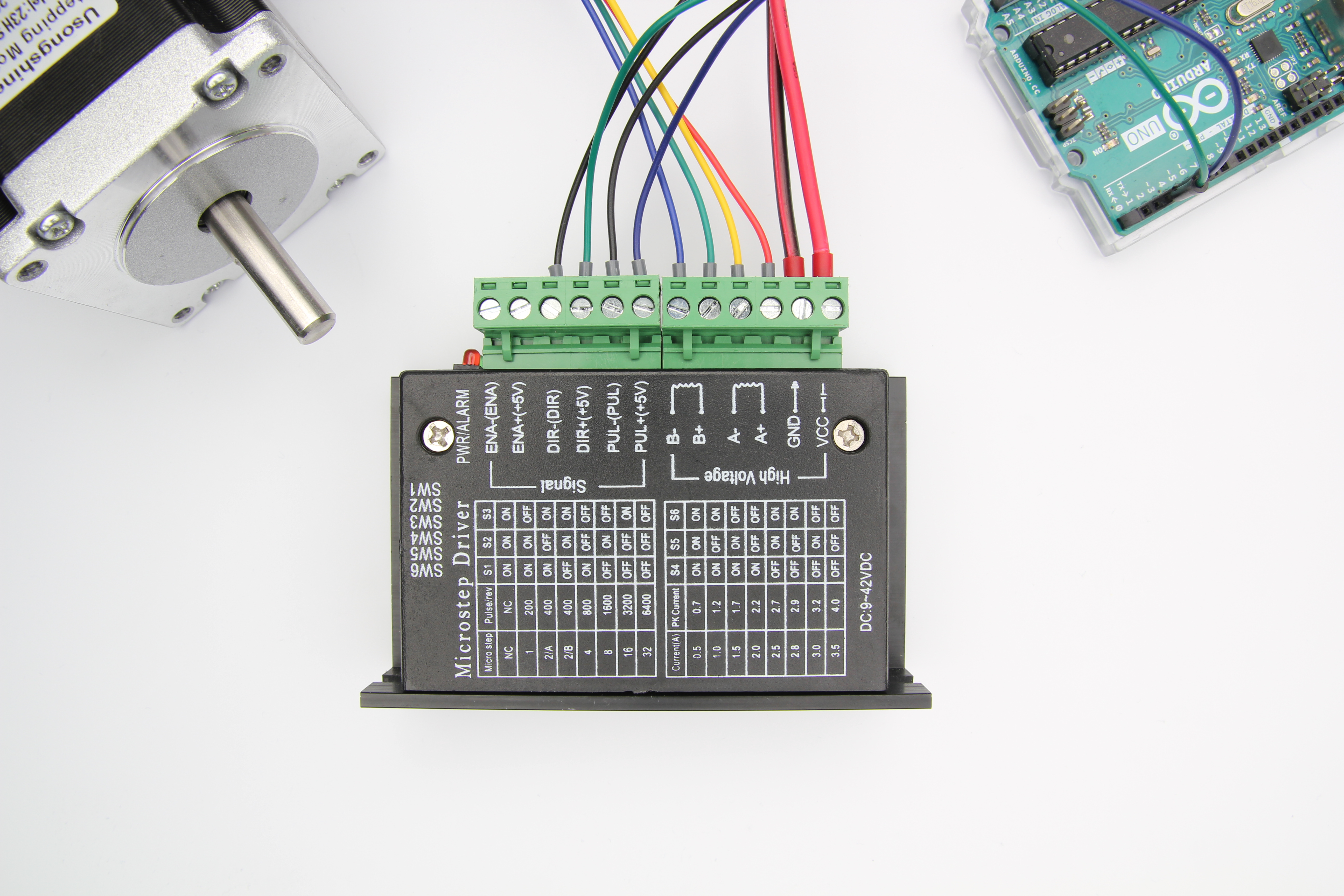
In this tutorial you will learn how to control a stepper motor with TB6600, AccelStepper and Arduino. Wiring diagram and many example codes included!
flint smelt
@twin ginkgo Spelling, copy the suggested spelling and replace the class name of the last 3 instances
obtuse spruce
Mind you, I've not use these, but that diagram makes more sense to me.... If the inputs are differential pairs (+/- inputs), then you just ground the -, and drive the + via an output pin - and you're good.
fallen canyon
ok ill have a look thanks for the info there. all of this is rather new to me so im following any info i can find. big thing is with this type of thing is there are several ways to come to the same conclusion to my understanding
twin ginkgo
i tried but does not work
flint smelt
@twin ginkgo you typed 32 instead of 23
flint smelt
No problem
fallen canyon
lol the single most common issue i find in all my code is typos
tidal peak
@obtuse spruce thx, I figured that out, lol. I had that originally, but at some point I accidentally changed it. There was another issue I was trying to solve b4, then it started acting all goofy. Now I'm back to my original issue 😅
ok, new issue 😅 , so I'm trying to make a pulse with this timer, however it doesn't seem to make a difference in the pulse unless I change the difference in count that it checks for by atleast 4. This doesn't make sense to me because it's running at 600MHz, this should be more than enough to check the count before the count even changes.
#define pin 4
#define WIDTH 14

volatile uint32_t *GPT1_CTRL = (uint32_t*)0x401EC000;
volatile uint32_t *GPT1_COUNT = (uint32_t*)0x401EC024;
volatile uint32_t *ROOT_DIV = (uint32_t*)0x400FC014;

uint32_t time1 = 0;
uint32_t state = 1;

void setUpTimer(void) {
  *GPT1_CTRL |= ((0b1001 << 6) | 0b1);
}

void setup() {
  Serial.begin(9600);
  while (!Serial.availableForWrite());
  pinMode(pin, OUTPUT);
  delay(1000);
  Serial.println("Starting");
  Serial.flush();
  setUpTimer();

  while (1) {
    if (*GPT1_COUNT >= time1 + WIDTH) {
      digitalWriteFast(4, state);
      state ^= 1;
      time1 = *GPT1_COUNT;
    }
  }
}

void loop() {
}
I can never see my own typos! Long wild goose chases 'cause I can't see I've swapped x for y....
So, you are trying to produce a 50% duty cycle square wave with a period of 2*WIDTH, right?
tidal peak
yes
right now I get this
however, if I change the Width to 13
I get that, no difference
obtuse spruce
welll.. there are some nits in that code
tidal peak
but if I keep changing it, it just like jumps
nits?
at WIDTH = 12 it becomes this
it just jumps down by like 150ns
when b4 it didn't change at all
obtuse spruce
uint32_t nextEdgeTime = 0;

...

  while (true) {
    auto counterNow = *GPT1_COUNT;
    if (counterNow >= nextEdgeTime) {
      digitalWriteFast(4, state);
      state ^= 1;
      nextEdgeTime = counterNow + WIDTH;
    }
  }
try that
tidal peak
what is auto?
obtuse spruce
though, even that has a nit.... but the first two things to fix are: 1) only read from the timer once! two reads may well produce two different results! 2) do the add just once (not really serious thing... but good form)
auto means "make this type the same type as the expression being assigned to it"
you can use uint32_t there if you prefer
tidal peak
ah, didn't know that, neat
well, it did change something, without changing any values I get this
hmm, issue is still there
WIDTH being 13-16 gives me the same pulse
obtuse spruce
is that right? I don't know what the timer clock frequency is or what WIDTH is now (13?)
beyond 16, does each +1 of WIDTH give the correct slow down in this square wave?
obtuse spruce
what is the counter clock speed?
tidal peak
tbh, I'm not exactly sure. I set the source to the ipg clock which I know has a 1/4 divider from the arm clock
the clocks in this micro are very confusing to me
I do know that approximately 20million counts is 1 second
not exactly, but close
obtuse spruce
so... er... you may be hitting the speed of the code here.... ? Seems unlikely but...
try this version:
uint32_t nextEdgeTime = 0;

...

  nextEdgeTime = *GPT1_COUNT + WIDTH;

  while (true) {
    auto counterNow = *GPT1_COUNT;
    if (counterNow >= nextEdgeTime) {
      digitalWriteFast(4, state);
      state ^= 1;
      nextEdgeTime += WIDTH;
    }
  }
the micro speed should be going 30X faster than the timer, and it shouldn't take that many cycles to set and check everything, let alone 4*30X
obtuse spruce
The difference here is that the trigger times, as you can see are based on an absolute time base - so the speed of the code is less relevant
whereas before, if for some reason the code took longer, you'd see what you see....
(one wonders if the core libs. for this chip have the Serial library using some interrupt to do stuff in the background.....)
tidal peak
wow, that's jittery
obtuse spruce
well... that tells me that your code can't keep up with your timer
tidal peak
could interrupts be going on
obtuse spruce
I think - perhaps - that the clock in use for the timer is faster than you think
obtuse spruce
(mind you - aside from this - you realize that that timer can produce that pulse width on an output pin with no code help at all, right?)
obtuse spruce
you could try turning off interrupts around the whole thing - but really, if you need to do that, then your approach is not really going to work in your project - you shouldn't ever need to turn off interrupts like that
obtuse spruce
try the low reference clock -- 0b1100 << 6 in your set up code
that's a 32kHz clock, and so widths down to 1 should be quite stable in your scope
tidal peak
I changed the width and it's jittering again, what
oh, for my project I need to creat 1us - 4us pulses
so it needs to be fast
and more specifically 1us LOW 3us HIGH or 3us LOW 1us HIGH
and they will vary as it will be sending 1s and 0s as those depending on the data I want
fallen canyon
@obtuse spruce thanks for that link got the stepper turning at least. now i just have to figure out how to wire my switches and potentiometer and make the code to handle that
tidal peak
so a PWM pulse is impractical for this
obtuse spruce
personally - I'd never attempt that in code - I'd have the HW do it. -- wait, why? that seems exactly like what the PWM output controls can do
tidal peak
cause I'd need to switch between the two variants very fast and it'd be a few bytes at a time. This personally seems easier I guess to me atleast, well if it was working as expected
I did it on a arduino board b4 using a similar method, however I'm trying to use this faster one to get more precision
obtuse spruce
but you could change from 25% duty to 75% with one write to a compare register
tidal peak
I also have to detect if incoming bytes are ones or zeros and the easiest way I found was to detect high or low around the 2us mark
which I would need a timer for
obtuse spruce
well... I don't know this chip well enough.... I'm doing very similar kinds of things (though at much slower speeds) in my project on an SAMD21 - and doing it all in hardware: pulse generation, variable width under software control, sampling input signal against a clock...
tidal peak
idk, it's just weird to me that it's acting this way at all
and it's generating an inconsitent pulse
obtuse spruce
sleep states? though no idea why it would be sleep....
tidal peak
I uped the count and it's consistent again
it's like b4 it was sometimes detecting it on time and sometimes late
I wonder if something is causing an extra delay in the loop. Maybe in the internal libraries? idk, ugh, well, thx for helping anyways
obtuse spruce
no - I doubt it - digitalWriteFast should be quick - but there might well be a bus sync delay in reading the timer's counter.
(there is in SAMD21)
anyhow - night time for me
good luck
safe halo
Any Idea what this means?
xtensa-esp32-elf-ar: .pio\build\heltec_wifi_lora_32_V2\libc1c\libESPmDNS.a: Error reading .pio\build\heltec_wifi_lora_32_V2\libc1c\ESPmDNS\ESPmDNS.cpp.o: No such file or directory
*** [.pio\build\heltec_wifi_lora_32_V2\libc1c\libESPmDNS.a] Error 1
seems like a file is missing
safe halo
Any Idea what would be causing this??
 lilac mountain
not sure
try restarting your computer? i've never seen that error but it might be worth a shot
safe halo
I had to do a disk scan to fix it.
obtuse spruce
Morning
 glad reef
Hi all, I'm working with the USBHost library and I'm attempting to work out how to register modifier keypresses without having to push a non-modifier key. Unless I'm mistaken, it seems that the .getModifers() function can only be called in the keyPressed() or keyReleased() callback. Neither of which are triggered when something like the Ctrl key is pressed down.
 fresh field
Hello, I bought a ItsyBitsy nRF52840. I downloaded the latest Version of circuitpython and put it into the itsyBitsy driver. Then I copy a Code from Adafruit, for controlling LEDs. And I pastet it into the code.py file. But the next time I put in the controller, I had by mistake deleted the code.py file. Then I downloaded the file of circuit python new and new and new, but the code.py file was not in there. So I made a new code.py file with the code, but it didn´t worked. Pls help me. What can I do?
odd fjord
@fresh field You should only have to reload the code.py file -- not everything else... Are you seeing any error messages? Is LED on the ItysBity blinking a color pattern?
fresh field
How can I reload the code.py file? No there aren´t Error Messages. Yes, the LED on the ItsyBitsy is blinking
twin ginkgo
im working with an rtc im trying to make led's light up for pacific days and months and i have this it worked for the time but its not working for the months and days``` if (now.month() == 1)
mcp3.digitalWrite(0, HIGH);
if (now.month() == 2) {
mcp3.digitalWrite(0, HIGH);
mcp3.digitalWrite(1, HIGH);
}
if (now.month() == 3) {
mcp3.digitalWrite(0, HIGH);
mcp3.digitalWrite(1, HIGH);
mcp3.digitalWrite(2, HIGH);
}
if (now.month() == 4) {
mcp3.digitalWrite(0, HIGH);
mcp3.digitalWrite(1, HIGH);
mcp3.digitalWrite(2, HIGH);
mcp3.digitalWrite(3, HIGH);
}
and i connected everything the same in wires too exept the designation on the mcp chips
odd fjord
And can you post it here.
actually - it would be best to post follow-up questions to #help-with-circuitpython -- this channel is for arduino help
The blinking LED is telling you there is error in the code.
 delicate coral
@twin ginkgo To start with, when do you set the LEDs low? If you don't turn some of them off, once they're on they'll stay on forever.
obtuse spruce
@twin ginkgo - so ideas how to code that block more clearly:
1)
  if (now.month() >= 1)   mcp3.digitalWrite(0, HIGH);
  if (now.month() >= 2)   mcp3.digitalWrite(1, HIGH);
  if (now.month() >= 3)   mcp3.digitalWrite(2, HIGH);
  if (now.month() >= 4)   mcp3.digitalWrite(3, HIGH);
  switch (now.month()) {
    case 4: mcp3.digitalWrite(3, HIGH); // fall through
    case 3: mcp3.digitalWrite(2, HIGH); // fall through
    case 2: mcp3.digitalWrite(1, HIGH); // fall through
    case 1: mcp3.digitalWrite(0, HIGH); // fall through
    default: ; // nothing
  }
  mcp3.digitalWrite(0, now.month() >= 1 ? HIGH : LOW);
  mcp3.digitalWrite(1, now.month() >= 2 ? HIGH : LOW);
  mcp3.digitalWrite(2, now.month() >= 3 ? HIGH : LOW);
  mcp3.digitalWrite(3, now.month() >= 4 ? HIGH : LOW);
The last example might be hitting what is the issue - what brings those lines low? - as @delicate coral pointed out as well.
twin ginkgo
oh i have the led low at the end
so if (now.month() == 1){ mcp4.digitalWrite(1, HIGH); mcp4.digitalWrite(2, HIGH); mcp4.digitalWrite(3, HIGH); mcp4.digitalWrite(4, HIGH); mcp3.digitalWrite(5, HIGH); mcp3.digitalWrite(6, HIGH); mcp3.digitalWrite(7, HIGH); mcp3.digitalWrite(8, HIGH); mcp3.digitalWrite(9, HIGH); mcp3.digitalWrite(10, HIGH); mcp3.digitalWrite(11, HIGH); }
i can try the first one see what happens
 vivid rock
instead of having 11 similar commands in a row, I'd write a loop:
for (i=0; i<now.month(); i++) {
    mcp3.digitalWrite(i, HIGH);
}```i noticed it was high
vivid rock
sorry, I seem to get the logic wrong - what is the rule you are trying to implement? what is the relation between month number and LEDs which need to be on?
twin ginkgo
so as the months goes buy each led will turn on one led per month and when the new year starts it will turn all off but not the first led
vivid rock
so for month 1, you need only first LED on?
twin ginkgo
yeah
vivid rock
then my code is correct (assuming your LEDs are indexed 0...11)
delicate coral
@twin ginkgo Good naming makes your code easier to read
Instead of
Adafruit_MCP23017 mcp1;
Adafruit_MCP23017 mcp2;
Adafruit_MCP23017 mcp3;
Adafruit_MCP23017 mcp4;
you might try
Adafruit_MCP23017 minuteLeds;
Adafruit_MCP23017 hourLeds;
Adafruit_MCP23017 monthLeds;
Adafruit_MCP23017 dayLeds;
i woudl really suggest using loops - makes it much easier to read than having 12 "if"s
twin ginkgo
i tried some loops with the clock but i just have issues
 candid topaz
o_O
twin ginkgo
and i find that this works with no issues till i implemented the days and months
delicate coral
@twin ginkgo what happens when you implement days and months?
twin ginkgo
the clock works but not the days and months lights dont want to light up
delicate coral
and if you comment out the rest of the clock do the days and months work?
vivid rock
can it be hardware issue? did you set up MCP23017 addresses correctly?
twin ginkgo
idk i can try
delicate coral
because you may have a problem with your setup with the MCP23017 I/O
if the days and months never work, solve that problem first
twin ginkgo
i thought it might of been that but i looked it over and they are
i thought it might of been power issues but that is not either
ill try to take out the clock
delicate coral
yeah, test each bank individually to make sure it works.
twin ginkgo
could that be i thought it would still work as an address
candid topaz
light up all leds in all banks
in 2 loops
in setup and comment everything in loop
and look for i2c address till it works ;-))
or use i2c scanner
to check how many chips it founds
maybe it could be wirering problem
twin ginkgo
ill test out the led to turn on high first
candid topaz
lib is little weird that you cant set address manualy
@twin ginkgo so use in mcp1.begin(1) not 010
just from 1 to 7
twin ginkgo
hmmm ok ill look at them why does mcp 1 and 2 work then?
delicate coral
@twin ginkgo What addresses did you wire the address lines of the chips to?
twin ginkgo
hmm ok
candid topaz
so simply set number from 0 to 7
delicate coral
you want a leading B on your numbers\
if you're going to use binary
I see a writeup on the address lines:
A0, A1, and A2 are the address pins. You only need be concerned about these pins if you are using multiple MCP23017 chips. These pins are externally biased, meaning you provide voltages to them to create different addresses. Since there are 3 pins, you can create a total of 8 different addresses (23=8). This is only necessary if you are connecting multiple ICs, so that we can distinguish between them. For example, if I grounded A2 and A1 and held A0 HIGH, this would create the address 001. Being that we are grounding all 3 pins, the address will for the address pins will be 000. But if you are connecting up to 8 MCP23017s, you will need to configure these pins so that each has a unique address: 000, 001, 010, 011, 100, 101, 110, 111. This way, you will be able to uniquely address each of them.
B000, B001, B010, B011, B100, B101, B110, B111. = 0, 1, 2, 3, 4, 5, 6, 7
twin ginkgo
ok sorry was distracted let me read really quick
ok so i would need a B to make it correct?
candid topaz
yeah
twin ginkgo
so i throw one chip B000 all ground saved it but nothing
delicate coral
So in the minute leds you ground A2, A1, A0
for the hour leds you ground A2, A1, and connect A0 to voltage.
for the month leds you ground A2, A0 and connect A1 to voltage
for the day leds you ground A1, A0 and connect A2 to voltage
for the mcp5 (year?) you ground A2 and connect A1, A0 to voltage
twin ginkgo
the year i havent touched yet due to still learning that
twin ginkgo
i have a 7 segment 4 digit for the year
 nova comet
The contact on this bluetooth module just came off, anything i can do or do i need a new one
stuck coral
@nova comet looking at the PCB, can you see the track going to a SMD part?
If so, you can solder a wire to that lead if you'd like, not great but it'll work
delicate coral
@twin ginkgo don't worry about the year, did you ground/pull high all the address pins as I describe above for the others?
delicate coral
to be clear, I'm talking about did you wire those MCP23017 chips that way - this is trying to make sure your code "addresses" match the wiring you did.
stuck coral
Oh its a ground, that makes it easy @nova comet
stuck coral
So look at the ceramic cap next to the LED, one side should connect to the ground plane @nova comet
twin ginkgo
on low
candid topaz
anh, thats wiring problem i think
nova comet
@stuck coral
delicate coral
@twin ginkgo but did you do something different for the month and day chips?
twin ginkgo
stuck coral
Solder to the cap above that LED @nova comet
twin ginkgo
stuck coral
Make sure to conenct to the side connected to the ground plane and not the other side
Looks like left pin
twin ginkgo
the side in side the board is the .
nova comet
@stuck coral ?
twin ginkgo
yeah its the resistors on the left side
stuck coral
@nova comet that cap correct, but I think its the left side pad not right. Make sure either visually or with a multimeter. The other side probably connects to the LED and/or the power pin which you do not want to connect to
twin ginkgo
hmm thats what poeple told me to use and i have it on the clock and it still works
delicate coral
that's for address 0.
twin ginkgo
ill throw them directly
delicate coral
"And we connect the address pins, pins A0, A1, and A2, to ground. This makes the address of these 3 pins 000. Later on in our code, this will be important for addressing this MCP23017 chip."
twin ginkgo
in the code i have it like this for now```#include "RTClib.h"
#include <Adafruit_MCP23017.h>
#define NUM_ONES_LEDS 4
RTC_DS3231 rtc;
Adafruit_MCP23017 mcp1;
Adafruit_MCP23017 mcp2;
Adafruit_MCP23017 mcp3;
Adafruit_MCP23017 mcp4;
Adafruit_MCP23017 mcp5;
void setup() {
// put your setup code here, to run once:
//mcp
mcp3.begin(B000);
mcp3.pinMode(0, OUTPUT);//JAN
mcp3.pinMode(1, OUTPUT);//FEB
mcp3.pinMode(2, OUTPUT);//MAR
mcp3.pinMode(3, OUTPUT);//APR
mcp3.pinMode(4, OUTPUT);//MAY
mcp3.pinMode(5, OUTPUT);//JUN
mcp3.pinMode(6, OUTPUT);//JUL
mcp3.pinMode(7, OUTPUT);//AUG
mcp3.pinMode(8, OUTPUT);//SEP
mcp3.pinMode(9, OUTPUT);//OCT
mcp3.pinMode(10, OUTPUT);//NOV
mcp3.pinMode(11, OUTPUT);//DEC
mcp3.pinMode(12, OUTPUT);//
mcp3.pinMode(13, OUTPUT);//
mcp3.pinMode(14, OUTPUT);//
mcp3.pinMode(15, OUTPUT);//
}
void loop() {
mcp3.digitalWrite(0, HIGH);
mcp3.digitalWrite(1, HIGH);
mcp3.digitalWrite(2, HIGH);
mcp3.digitalWrite(3, HIGH);
mcp3.digitalWrite(4, HIGH);
mcp3.digitalWrite(5, HIGH);
mcp3.digitalWrite(6, HIGH);
mcp3.digitalWrite(7, HIGH);
mcp3.digitalWrite(8, HIGH);
mcp3.digitalWrite(9, HIGH);
mcp3.digitalWrite(10, HIGH);
mcp3.digitalWrite(11, HIGH);
just to work with one chip to see if i can get them to light up if not its wiring
delicate coral
but MCP3 isn't at B0000
twin ginkgo
i have B000
nova comet
@stuck coral how can i check visually my multimeter is broken
delicate coral
can you take a close up picture of the month led MCP23017?
so I can see where the resistors are wired to?
twin ginkgo
yeah
stuck coral
@nova comet left side should not have a trace, you should only see a ground plane, while on the right there will be a trace that goes to the LED and/or power pin
twin ginkgo
nova comet
I think its the left side? Can you see anything @stuck coral
stuck coral
Im 99.99999% certain, just not being able to take a good close look makes me nervous
nova comet
Honestly your guess is good as mine
So just to confirm this circled part is what i solder to?
delicate coral
@twin ginkgo it looks like all three address lines are wired to ground, right?
twin ginkgo
yes
stuck coral
@nova comet correct
delicate coral

Electrical Engineering Stack Exchange
I'm a total newbie fooling around with a project of mine.
I want to use an MCP23017 I2C port extender (Data sheet) for my Arduino project.
The chip has three hardware pins that must be externally
so you don't need resistors on the address lines.
delicate coral
for the month leds you ground A2, A0 and connect A1 to voltage. so move A1. Then change your code to
mcp3.begin(B010);
and try it again.
if it doesn't work, you need to check your wiring of the SDA/SDL lines, and make sure you've daisy chained them from the other chips right
twin ginkgo
ok i got leds to work i think it was the sda and sdl might of been switched
let me reconnect all the chips and go with the other script
and check all the chips
led did turn on
nova comet
Lets pray @stuck coral
stuck coral
Yeah, that will probably break off easily, looks like you didnt totally melt the origonal solder
stuck coral
Thats good, it it breaks off than just put your iron on the side of the cap, and put a bit of extra solder on it, then while its still melted put the wire back on and melt the bit of solder still left on it with the melted solder on the cap. Best way I can describe it.
stuck coral
Nice, try to keep the pads on, they are a tad important 😉
nova comet
Yup
twin ginkgo
so i got the daisy chain working where all chips work led from each chip lights up
ok i figured it out what was wrong the connection between the rtc chip and the other chips was wrong
twin ginkgo
ok im trying to rewire the led's to correct order and i did 10 high but different leds turn on as well
#include "RTClib.h"
#include <Adafruit_MCP23017.h>
#define NUM_ONES_LEDS 4
Adafruit_MCP23017 mcp3;
void setup() {
// put your setup code here, to run once:
//mcp
mcp3.begin(B010);
mcp3.pinMode(0, OUTPUT);//JAN
mcp3.pinMode(1, OUTPUT);//FEB
mcp3.pinMode(2, OUTPUT);//MAR
mcp3.pinMode(3, OUTPUT);//APR
mcp3.pinMode(4, OUTPUT);//MAY
mcp3.pinMode(5, OUTPUT);//JUN
mcp3.pinMode(6, OUTPUT);//JUL
mcp3.pinMode(7, OUTPUT);//AUG
mcp3.pinMode(8, OUTPUT);//SEP
mcp3.pinMode(9, OUTPUT);//OCT
mcp3.pinMode(10, OUTPUT);//NOV
mcp3.pinMode(11, OUTPUT);//DEC
mcp3.pinMode(12, OUTPUT);//
mcp3.pinMode(13, OUTPUT);//
mcp3.pinMode(14, OUTPUT);//
mcp3.pinMode(15, OUTPUT);//
}
void loop() {
mcp3.digitalWrite(10, HIGH);
}
but other pins turn on as well
i can do 1-9 and the pins turn on the correctly but when i do 10 it turns on random pins
or should i do binary for pins?
nova comet
@stuck coral so the bluetooth boi is flashing and my arduino wont let me upload code
 wanton mirage
lo folks, I have a quicky question. What is the smallest value of potentiometer that is safe to use with an AVR based arduino?
fallen canyon
here is my code ->https://pastebin.com/bYvDL8xk here is the error its spitting out -> https://pastebin.com/ry0xPBGy im not sure why the if statement isnt working. i am used to another format of coding than this one but if i can be pointed in the right direction that would be greatly appriciated
 delicate coral
@fallen canyon I think this statement needs to be inside the setup() function:
if (ReversePin HIGH) {
    // Set the spinning direction CW/CCW:
    digitalWrite(dirPin, HIGH);
} else {
    // Set the spinning direction CW/CCW:
    digitalWrite(dirPin, LOW);
}
or inside the loop
fallen canyon
ok the original code didnt have it inside of a loop...
but it also didnt have the if statement as it was a single direction setup
delicate coral
I mean:
void loop() {

if (ReversePin HIGH) {
    // Set the spinning direction CW/CCW:
    digitalWrite(dirPin, HIGH);
} else {
    // Set the spinning direction CW/CCW:
    digitalWrite(dirPin, LOW);
}
  // These four lines result in 1 step:
  digitalWrite(stepPin, HIGH);
  delayMicroseconds(200);
  digitalWrite(stepPin, LOW);
  delayMicroseconds(200);
}
``no - loop() and setup() define functions. your "do something" code needs to be inside those functions.
so put it in setup() if it's only supposed to be done once.
put it in loop() if it's supposed to be done repeatedly
stuck coral
@nova comet Lol, sorry, thats what I was nervous about
And also sorry for not getting back quick, was making dinner
delicate coral
what exactly is it yelling
fallen canyon
`Arduino: 1.8.13 (Windows Store 1.8.39.0) (Windows 10), Board: "Arduino Uno"
In file included from sketch\always_on_stepper.ino.cpp:1:0:
C:\Users\calic\Documents\Arduino\always_on_stepper\always_on_stepper.ino: In function 'void loop()':
C:\Program Files\WindowsApps\ArduinoLLC.ArduinoIDE_1.8.39.0_x86__mdqgnx93n4wtt\hardware\arduino\avr\cores\arduino/Arduino.h:40:14: error: expected ')' before numeric constant
#define HIGH 0x1
^
C:\Users\calic\Documents\Arduino\always_on_stepper\always_on_stepper.ino:15:18: note: in expansion of macro 'HIGH'
if (ReversePin HIGH) {
^~~~
exit status 1
Error compiling for board Arduino Uno.
This report would have more information with
"Show verbose output during compilation"
option enabled in File -> Preferences.
`
bleh... il pastebin that next time
stuck coral
ReversePin == HIGH is what you want if I had to guess
fallen canyon
ok so its a = operator
stuck coral
==
fallen canyon
yeah
stuck coral
= sets a variable, == is a comparison
fallen canyon
yeah alright cool
its a ton like the other language ive been dealing with for years
but there are a few minor differences
stuck coral
Well, when you leave the safty net of the Arduino framework Im sure you wont feel that quite as much but ig.
fallen canyon
well the lang ive been using for years gives a good baseline structure to coding logic
delicate coral
what lang?
fallen canyon
everything else is syntax and structure for the most part
its called denizen
its a minecraft scripting lang
thanks guys that compiled without errors
time to test
twin ginkgo
ok so i have an issue i have leds in there own row connected to ground and one wire to one pin ill post a pic in a seconded i have one pin turn high one pin turn low i disconnected power to reset the chip when i put the power back a few leds light up i take one wire from a powered led touch it to a non powered led it does not turn on but if i touch the same led that it was pluged into it turns on
like the rails are connected underneath
nova comet
@stuck coral it should be possible to connect to the bluetooth module within a custom app correct? Say, if i wrote my own iphone app
stuck coral
Well if it supports GATT then yes, if its only serial than in a sort of cludgy way
nova comet
You mean if the bluetooth module is?
stuck coral
Depends on what your module supports
fallen canyon
hmm so i have the code changed around but the if statement doesnt seem to be working. when i ground pin 5 it doesnt change direction here is the code https://pastebin.com/8cC2Rk4h
nova comet
Say i used this @stuck coral
Basically what i want to do is send the state of the chess board to my iphone and ill write an app that does whatever with that data
Would I be able to pair from within the app? Or at least from ios settings?
Or do i need to use a third party app to pair
stuck coral
So, it will be a serial interface
Which is a quite cludgy solution
You can use it, but serial over BT when you want to use it in an app tends to not be great.
stuck coral
Do you also need a new micro?
nova comet
Micro?
stuck coral
The microcontroller, did you mention earlier you needed to replace it?
nova comet
Oh no im replacing the ble chip
stuck coral
Oh okay. Well Im not sure what external chipset I would suggest, let me look to see what Arduino would support
Just saying, the nRF52840 itsy bitsy is $6 more than the BT module you were talking about, and it would act as the micro aswell, and its really good with bluetooth. Will look for another solution though
nova comet
What about wifi
stuck coral
Well I wasnt aware of wifi, what are you using now for that?
nova comet
I have no chipset for wireless connection thats what im shopping for
stuck coral
Do you want to use them at the same time (Normally this is a no, since BT apps have internet connections aswell)
nova comet
I mean i could use wifi instead of Bluetooth if Bluetooth wouldn’t be good
stuck coral
So no? If no, than I'd look at a ESP32 since it has both WiFi and bluetooth, and you can get them for $20 on Adafruit which is less than a seperate wifi and BT breakout
And is a fast processor to boot
Would all be nice and compact, and cheaper
You just cant run the BT and WiFi at the same time
And the ESP32 feather has a battery charger if you were going that route
fallen canyon
yeah im not sure why my code wont reverse the motor... any idea IoT?
seems to be blowing right past the first if statment and not running whats in the braced area
goin straight for the else there
stuck coral
Let me take a look, Im playing a video game and cooking so might take me a sec
stuck coral
I dont know what youre trying to do with that if statement
fallen canyon
so when i drop pin 5 to low i want the motor to reverse
stuck coral
If you had read a digital value before that line it would be valid, but you have it as a output
fallen canyon
so i need that portion to be a read?
rather than output
if i could find a solid guide to walk me through the variables i would probably do fine but i currently havent found one explaining more than like 2 things at a time lol
nova comet
@stuck coral i think you’re misunderstanding me. I dont need wifi and Bluetooth. Its one or the other. I need my arduino to communicate with a phone app, sending data back and forth. Which do you think is the better solution?
stuck coral
Oh okay, well if you want wifi I would still go with ESP32 @nova comet , if you want blutooth go with a nRF52 board, it wont be much more than just buying a module and if you get a feather you have the battery charger and have no wirey module mess
@fallen canyon What are you trying to do with ReversePin?
fallen canyon
reverse the motor
when the switch is on go clockwise and off counterclockwise
basically what im understanding is i need whatever read is in place of output
stuck coral
Ah, so first you need to change pinMode(ReversePin, OUTPUT); to pinMode(ReversePin, INPUT); and before your if statement you need to use the digitalRead(ReversePin) function;
fallen canyon
ok so let me make the changes and repost the code to verify i am folowing correctly
ohh and also have ya got a good recomendation for a guide i can follow
something that covers a larger scope than just basic code functions
stuck coral
You can get a lot out of the builtin examples and the Arduino.cc documentation, having a understanding of C is also important
fallen canyon
i kinda follow c
i just dont understand all of the input output and read stuff yet
stuck coral
new_var = digitalRead(ReversePin);
Oh wait
Lol, youre also using a constant as a variable
Also define a variable to store the state of the value you are reading
ReversePin just defines what pin it is
https://www.arduino.cc/en/tutorial/switch Here is a example thatll help you
Open-source electronic prototyping platform enabling users to create interactive electronic objects.
fallen canyon
cool
ill have a look
so for switches have to make them a var
that way it doesnt set it in a constant state?
stuck coral
Well first you werent setting it at all, and next is constants stay well... constant. You cannot change their value
if (ReversePin == HIGH) { this will need to be an if statement using said new variable
Not the constant, because right now youre asking it is ReversePin which is set to 5 equal to HIGH which is 1
Resulting in false
fallen canyon
so int is the variable
stuck coral
It is a type of variable
 glossy sierra
Anyone know a good place to start designing with a microcontroller and learning the design of them without the help of the arduino? I really want to start designing without a using a "prebuilt" platform.
stuck coral
Well do you mean Arduino boards or microcontrollers that work in the Arduino framework in general?
I would always recommend using a "prebuilt" platform, is there a design constraint working against you?
glossy sierra
I mean learning to design a raw micrcontroller board. It is easier with an arduino because all of the pins are set up but I want to learn to build a pcb with a microcontroller from scratch.
I juts dont know where to start
stuck coral
Oh I see, well if it's your first time I'd recommend basing it off an existing Adafruit design since all the boards are open source, you than change anything you want, and know the origonal design you're starting with works for sure. You would learn about the crystal, power supply, etc
glossy sierra
Okay thanks! Any good sources you know off of the top of your head, to learn the pins meanings and uses, that you can think of? Or is reading the manuals good enough? I am looking at some adafruit open source schematics and some of the pins I am confused on all of their uses. For example pin 13 says PA08/I2C/AIN8/SERCOM0.0+2.1/I2SMCK.
stuck coral
The datasheets for the chip you want to use will tell you what it all means
glossy sierra
I dont know what half of those are and if they are to any importance for low level pcb design
OKay
Thanks
stuck coral
Np, have fun, if you have more questions about the chip or making the board we're all total nerds for that stuff and you know where to find us
glossy sierra
Thanks again!
stuck coral
Also, as a side note for learning what those pins mean, reading a datasheet is almost a skill in itself, and the information is scattered all over the place so dont be afraid to ask a question and the search tool in your PDF viewer or browser will be a big savior
glossy sierra
👍🏽
fallen canyon
`int switch_pin = 5;
int dirPin = 2;
#define stepPin 3
byte leds = 0;
void setup() {
pinMode(switch_pin, INPUT);
pinMode(dirPin, OUTPUT);
pinMode(stepPin, OUTPUT);
}
void loop() {
if(digitalRead(switch_pin) == HIGH){
digitalWrite(dirPin, LOW);
}
else {
digitalWrite(dirPin, HIGH);
}
// These four lines result in 1 step:
digitalWrite(stepPin, HIGH);
delayMicroseconds(200);
digitalWrite(stepPin, LOW);
delayMicroseconds(200);
}`
anyone here that can tell me why my stepper motor just jitters when i pull the 5v off pin 5?
trying to make it rotate the other direction when it doesnt have voltage without having to ground it
 inland moat
how to write a code if user type a odd number red led light if even green led light up.then servo motor will rotate 180 degree when user complete order with the help of coding using python
for the servo part i havent learn so idk
safe halo
Anyone know what this is being caused by? My Dev board just continually reboots...
rst:0x3 (SW_RESET),boot:0x17 (SPI_FAST_FLASH_BOOT)
configsip: 0, SPIWP:0xee
clk_drv:0x00,q_drv:0x00,d_drv:0x00,cs0_drv:0x00,hd_drv:0x00,wp_drv:0x00
mode:DIO, clock div:2
load:0x3fff0018,len:4
load:0x3fff001c,len:1044
load:0x40078000,len:8896
load:0x40080400,len:5828
entry 0x400806ac
ets Jun  8 2016 00:22:57
@fallen canyon if you disconnect a pin from 5v without grounding it (this is usually called "floating pin") , the voltage reading on this pin becomes unpredictable; it can be HIGH or LOW at random
the usual way to deal with it is declaring the pin using pinMode(pin, INPUT_PULLUP) and connect/disconnect it to ground only
some microcontrollers (e.g. those using M0 chips) also have INPUT_PULLDOWN mode
north stream
@inland moat There are servo libraries available with example code that make it a lot easier.
@safe halo That looks like the "I am booting" messages, but what caused the device to boot does not appear to be shown.
north stream
There's a useful writeup here https://learn.adafruit.com/adafruit-arduino-lesson-14-servo-motors/overview

 clear valve
I'm using an ESP32 airlift with a samd21 based board. Whenever I pass in a bad password to the access point I get the "WL_DISCONNECTED" status instead of the "WL_CONNECT_FAILED" status. I'd like to handle these events differently; anyone know why the statuses are returning like that?
 waxen sleet
twin ginkgo
waxen sleet
twin ginkgo
so im working with mcp23017 i turned off one pin but its still on and other pins if i turn on it turns on other leds why is that
inland moat
@north stream okay thank u
now i have an error where i make the led in the circuit light up and make it sleep
but then the led still lights up permanently so how can i rectify that?
fallen canyon
@vivid rock thanks for the reply. I found that to work with the pullup resistor quite well now the only thing i notice is its fairly noisy in one direction with the stepper but doesnt seem to have any issues turning
clear valve
I'm using an ESP32 airlift with a samd21 based board. Whenever I pass in a bad password to the access point I get the "WL_DISCONNECTED" status instead of the "WL_CONNECT_FAILED" status. I'd like to handle these events differently; anyone know why the statuses are returning like that?
Looking into this a bit more, it looks like the ESP32 is getting a "4WAY_HANDSHAKE_TIMEOUT" disconnect status when the password is incorrect. I would expect this to instead return "AUTH_FAIL", is this normal?
cyan jasper
I want to create programmable supply for one of my projects. I put a bit of thought and I come up with this. Would this work? I also thought about putting npn on bottom but then id have offset voltage, im not sure of that matters or not but transistor gonna be running in saturation mode, there will be 0.2-0.3 V between collector and emitter.
north stream
@inland moat I'm not very familiar with GPIO behavior during sleep. I'd guess turn the LED off and then sleep, but I could be misunderstanding.
solid dawn
weird question. anyone know the unit that would be used to describe the value that photocells/resistors creates?
stuck coral
A voltage divider? Or a multimeter?
cedar mountain
Are you looking for "lux"? https://learn.adafruit.com/photocells/measuring-light
 stuck coral
Oh unit lol, I need to read better.
odd fjord
They measure lux but the output is in ohms. It’s a variable resistor.
solid dawn
thanks chaps
north stream
Hello, anyone knows how i can change this code to work with Elegoo tft display. please give me the full code that can work with the Elegoo display, thank you! https://hatebin.com/vnirnalemy please ping me, thank you!
cyan jasper
@north stream sorry to jump in without reading rest of the thing but if its arduino uno (atmega328 [probably all other 8 bit AVRs]) GPIO runs asynchronous mode so they keep their state when sleeping. they are latched at the start of the sleep
north stream
No worries, I don't know much about this, so I'm happy to have people jump in. That does confirm my guesswork, at least.
inland moat
how can i add a servo motor code into my python codings when i already have another import function
For example
i already have this. import pyfirmata from time import sleep port1='COM3' board = pyfirmata.Arduino(port1) ledred = board.get_pin('d:11:o') ledgreen = board.get_pin('d:10:o')
But i want to add this below code too but have error.```
from pyfirmata import Arduino, SERVO
from time import sleep
port='COM3'
board1=Arduino(port)
sleep(1)
pin=13
board1.digital[pin].mode = SERVO
def setServoAngle(pin, angle):
board.digital[pin].write(angle)
sleep(0.015)
if 'mem'=="Y" or "N":
for i in range(0, 180):
setServoAngle(pin, i)
else:
board.exit()```
cyan jasper
No worries, I don't know much about this, so I'm happy to have people jump in. That does confirm my guesswork, at least.
I didn't wanna say something unrelated like if this was a samd (arm core) thing
north stream
@inland moat You didn't specify what error, but I noticed python if 'mem'=="Y" or "N": which has a few issues: you probably don't want quotes around 'mem', mem isn't declared anywhere, and you need full clauses for or. And I'm not sure why the if is there if the code will do the same thing for both "Y" and "N" (unless there are other possibilities)
 stable forge
if you want to check whether mem is "Y" or "N", use:
if mem in ("Y", "N"):
or, more obviously:
if mem == "Y" or mem == "N"
 minor brook
hi there, i'm having a strange problem, and i'm not sure where else to post. i bought a metro 328 and tried to plug it into my debian box to start playing with it, but while it blinks away happily i can't see it from the OS. dmesg, lsusb, and ls /dev/ all come up empty. i've tried swapping ports, cables, and even tried an ubuntu box, and nothing seems to work. other boards seem to have the same issue suddenly, and i can't explain it. other usb peripherals work fine. any ideas?
oh, and my user is in the dialout group, which i've heard matters sometimes
vivid rock
I expect you have read and followed the official instructions here: https://learn.adafruit.com/experimenters-guide-for-metro/linux-setup
right?

Adafruit Learning System
Harness the power of the Adafruit Metro by making 18 Circuits!
minor brook
@vivid rock i can't say i've followed them exactly, no, but they look quite similar to what i've already done. just for good measure i'll give them a run through and see if anything changes
thanks 👍
i went through the guide, but i get an error when i try to run ls /dev/ttyUSB*. there aren't any devices that match that completion, so it blows up, even though the metro is on and blinking its little blinker
this seems to match what i was seeing before
🤦♂️ okay, i figured it out
it was the cable after all. i got unlucky and the two that i chose to test with both appear to be power-only cables. i chose a third one that i know is good for data and it works fine
that's annoying... but at least now i can play with my new stuff. thanks for the help 🖖
 versed crystal
Been having a lot of fun working on my nrf5280 express. I know the bluetooth stuff is somewhat under construction, but I'm hoping someone can help me out -
I'm trying to turn bluetooth on and off based on a switch, to save power. I can get everything turned on successfully, but now I need to shut them back down again. A lot of the services have begin methods, but no end methods... is there something I'm missing?
vivid rock
@minor brook yeah, that can be really annoying when you try to debug a problem and it turns out something stupid like this 🙂 Happened to all of us
versed crystal
Hmm I think I've been thinking of it wrong... if I want to go into a "low power" mode, does that mean I need to work with the Nordic nRF52840 chip directly, and shut down until an interrupt, rather try to use the Adafruit libraries?
 clear fog
afternoon
Does anyone know how to get a Arduino to generate a 190khz square wave with a 50% duty cycle?
trying to do this with a v5 Trinket
delays seem to only get me to about 60khz
after that I have reached the limit of min delay
there must be a way to do this
stuck coral
There is a delay microseconds if you dont want to use a timer
Instead of milliseconds
Have you only tried delay()
north stream
Probably already using that if it's managed 60kHz.
stuck coral
Ah, then a timer will need to be used do you agree @north stream?
north stream
A tight loop could manage it, but either it would be bursty or the CPU couldn't do anything else, so yeah, a timer is probably the way to go, but I'm unsure how to configure one for that frequency.
clear fog
I'm trying to remove a NE555 from the circuit I'm building
north stream
Care to replace it with a DDS chip? I'm guessing not 🙂
clear fog
not really, it's no better then a 555 for a basic squarewave like this
I only need the Arduino to do this, and toggle it on and off, so taking up all the cpu cycles is not a problem
north stream
This page gives some info for fast frequencies using the CPU: https://michaelthessel.com/arduino-uno-high-frequency-pwm/
vivid rock
Which trinket do you use?
north stream
This one has some code that manages to eke 250kHz out of a timer https://arduino.stackexchange.com/questions/9408/generating-a-pwm-frequency-greater-than-125-khz-using-arduino-uno
clear fog
Trinket 5v logic
vivid rock
On uno? Wow, this is impressive
clear fog
@north stream thanks, I'll give it a read
otherwise I guess I'll just control a 555 with the tinket
vivid rock
5 v trinket is based on attiny85
clear fog
yes
clear fog
that is a nice little board
vivid rock
I had done some direct manipulation of timers on m0, but i am no expert - mostly copied and pasted other peoples code
north stream
Then again, if taking up all the CPU cycles is not a problem, you could theoretically replace the Arduino with the 555.
clear fog
the 555 is limited to 50%-100% duty cycle right?
my goal is to pulse the 190khz wave for 200ms every 30 seconds
stuck coral

GitHub
Fast-PWM library for SAMD21-based Arduinos (so far: the Nano 33 IoT (tested), the Zero (untested), and the MKR series (untested)) - ocrdu/Arduino_SAMD21_turbo_PWM
Not sure that will work out perfectly for you, but someone made a easy to use PWM lib using timers
In theory should be able to go up to 48Mhz if I remember right
Well, would be 24Mhz ig due to two slopes
Note: Still under development, and untested for the Arduino Zero and the Arduino MKR series.
Would take this note, but looks like a nice lib
 reef ravine
@clear fog there is a simple hack here to achieve <50% duty cycle on a 555
https://www.electronics-tutorials.ws/waveforms/555_oscillator.html
clear fog
Thanks guys , I'll check it out :-)
obtuse spruce
off hand - directly programming the TCC or TC units on a SAMD21 isn't all that hard to get PWM output at very high speeds with careful control of duty cycle. Hit me up if you need a tour of the basic code to code those registers.
 charred salmon
Trinket M0 has inputs that supposedly can be used as capacitive touch sensors with no additional input.
The tutorial pages have no information on how to do this in Arduino, only CircuitPython.
So... Help?
charred salmon
Nevermind. Eventually found it. It's the not entirely helpfully named "Adafruit FreeTouch Library"
"Arduino library for QTouch on samd21 microcontroller"
safe halo
I am looking to do a for loop to check a received string recieved over LoRa to see if it contains good data.
I want to check if the char is 0-9 or a , or / or : or . or # or 'RSSI'
The string should look like 1999138596,#79,24/07/20,10:16,5.300: RSSI-33 but sometimes it comes in as
\�~�����P��␃␃~�&���ն�␂�LR��[N8����P�l1␔␃␏o>!��7���␘�␚�L�F��#���pVJ����h: RSSI-113A0ֻ�W  �␄?�␗�␐���
 �␛�;iLX2��␙w���|��u�����s#�OdΩ���'␁�Y�␎␑M␑=�A���è]^qG���y,q����.$d␏a?Z<I*�8��)2s��d"})C^␎�����v␞��r    Q���4��s��_␕X␃~]␄���h���j␎�*`s���o8]�␁�(h���i�~0?�S�C�7␐-I��|\Y���-��D��␕Qc+�T?�Xf'?�S���Ɉ6͑��␖���T�␟��7T>␐m�х}X��j~�)
�x�ƌ53(0/2����␁ͼ�c�5���GT␛ms����� ␖+#v␏wP�Y�`�3␑R␕��"␖�5Ga␑␐␔��uGѥ=�:�+?␄䜿��Ĥ�␛I�}�أ�Γ����+��␙&�9      �.�h�: RSSI-113
This could be because what was sent was already garbage, or the transmission got garbled, or there is a bug in your reading code.
safe halo
I have it doing a standard ```c++
while (LoRa.available())
{
incoming += ((char)LoRa.read());
}
also the data that is being sent is output on the terminal and is fine. while (LoRa.available())
{
char c = (char)LoRa.read();
Serial.println(c);
incoming += c;
}
When do you this, does it also print the right thing?
safe halo
I am waiting for the error to recreate itself, usually after about 100 readings. I have changed my read code to the following to see f that helps.
    String incoming = LoRa.readString();
    incoming += ",";
    incoming += LoRa.packetRssi();
    Serial_Debug.print("--");
    Serial_Debug.println(incoming);
    incoming.toCharArray(recievedData, sizeof(recievedData));
    Serial_Debug.println(recievedData);
I am using the Heltec ESP32 Wi-Fi Lora V2 board and when I call ESP.getEfuseMac(); on 2 different boards I get the same number... Any Idea why?? I am using this as a way to create a unique serial Number for each device.
safe halo
So the receiving data matches when there is an error..
--W��x�␐�.      i�30��Ǫ�␝��C_�o�z␎�␞��)���'�)��,��5��gۗ,-111
W��x�␐�.        i�30��Ǫ�␝��C_�o�z␎�␞��)���'�)��,��5��g
Must be an issue with the transmission then....
candid topaz
wrong baud rate?
safe halo
No because it comes in fine prior to the error.
--1999138596,#188,24/07/20,10:55,5.300,-28
1999138596,#188,24/07/20,10:55,5.300,-28
--W��x�␐�.      i�30��Ǫ�␝��C_�o�z␎�␞��)���'�)��,��5��gۗ,-111
W��x�␐�. i�30��Ǫ�␝��C_�o�z␎�␞��)���'�)��,��5��g```It sounds like this is fairly reproducible, though? That's a good thing. 🙂
safe halo
happens quite regularly. But I cant induce the error
lone ferry
It might be that LoRa.readString() gives back garbage when there is no data available?
I haven't used this library before.
safe halo
The LoRa.ReadString() is only called when there is available data
  if (LoRa.available())
  {
    int packetSize = LoRa.parsePacket();
    if (packetSize)
    {
lora class implements Stream class, so i guess you can do lora.readStringUntil('\n') and send string with \n in the end
 robust flint
hi, i have a question...how will an "if-else" statement be executed in void setup() section in arduino?
stuck coral
As normally, do you have any sort of context for your question?
robust flint
well yes...lets say "if sensor reads "1" go forward else turn" in void setup...will it wait till the else part is executed and then start the void loop() ?
stuck coral
Yes, C is a low level language, there is not much black magic happening in the background and your processor can only do one thing at a time. In Arduino, your setup() is called once by some C that Arduino made for you, and once is completed it will call loop() in a while loop, so anything done in setup always happens before loop()
 quaint dune
How do I start learning IoT from basic and in which language
nova comet
Anyone have experience with bluetooth modules
Ive just connected mine and currently via the dsd tech app im receiving this and i want to know if its normal
nova comet
@stuck coral sorry to bother, any idea?
stuck coral
Not sure, Im not too familiar with serial over bluetooth modules does it just suddenly fill the screen with blank messages? @ me im working
 cunning reef
Hello, I recently started learning to program in Arduino, and I have a Mega2560 board that came in a starter kit. I connected a red LED in series with a 330 ohm resistor to pin 22 and the ground pin in the digital I/O section. Here is my code:
int redPin=8;
int bright=10;
void setup() {
pinMode(redPin,OUTPUT);
}
void loop() {
analogWrite(redPin,bright);
} My LED flashed momentarily and then turned off. It appears to have been burnt out. I have no experience with these pins, and did this to see if they would perform the same as pin 1-13 in the ANALOG IN section. Can somebody tell me what happened?
 woven mica
Try to increase the value of bright to something like 200. The value of 10 is low, you might not see the led light up
cunning reef
No, I then used a different test program that uses a digitalWrite command on pin 8 in the Analog in section. it still doesn't work. the LED also appears to be noticably blackened where it produces light.
woven mica
There must have been a short circuit then. Does different led work?
cunning reef
on the same pin?
woven mica
can be
cunning reef
well, my dad cleaned the board with isopropyl alcohol before he gave it to me, and there is some residue on it. Could that short it out?
woven mica
Isopropyl alcohol should evaporate quickly and the residuum is probably flux. I dont think flux can be conductive enough to cause short.
cedar mountain
Not sure how experienced you are. Any chance the resistor was in parallel instead of series?
Possibly the LED polarity was backwards?
cunning reef
Well, I'm 13 and I started a week or so ago. I have a lot of experience in general electronics, but not much in Arduino. The LED polarity is correct and the circuit layout goes like this: pin8 -> 330 ohm resistor -> LED (positive long leg) -> Ground
cedar mountain
Weird. That all sounds correct.
cunning reef
Yeah. I'm completely confused. I would try a different LED, but I only have a few more and I don't want to ask my dad to buy me more
Maybe the board is faulty?
I'm reading a Quora article that says a USB 3.0 port has a power limit of 900 mA. Could that do anything?
cedar mountain
The Arduino shouldn't be consuming nearly that much current, so the limit shouldn't affect it.
stuck coral
@nova comet Im not sure, would have to look at the code, but the fact you are getting the serial data in any capacity is a good sign
nova comet
:)
pine bramble
hello friends, I need some help with Arduino. I am following the lesson/tutorial on learn.adafruit and I'm having an issue getting the output for the CheckWifi101FirmwareVersion sketch.
It should look like this according to the lesson:
but im getting this in Adruino console:
stuck coral
Yes, open the serial monitor with the button on the upper right of the IDE
pine bramble
ah there it is lol
thank you so much!
Im new to Arduino IDE, im used to the console being down there in other IDEs
stuck coral
Understood
pine bramble
how do u write a makefile so that i can edit and compile with vs?
stuck coral
You just make a makefile for your project then use a plugin such as this https://marketplace.visualstudio.com/items?itemName=technosophos.vscode-make

Extension for Visual Studio Code - Run Make easily
pine bramble
thats for vsc right not vc?
stuck coral
Then no idea
pine bramble
okay tx anyways
 honest obsidian
Hello, folks. What's the point of the "Verify code after upload" option in the Arduino preferences? Isn't the code verified before upload so the compiler can check for compilation errors? Why verify after the code has been uploaded (and presumably) successfully? Thanks.
vivid rock
AFAIK, it verifies that the upload process was successful, by reading from arduino the uploaded file and comparing it with the file you were uploading.
 tardy hill
Hi guys, i need help with my Arduino mega 2560 and its timers. I want use PWM on 25KHz. But i bed know how it set. How trigger use for it
north stream
There's a lot of information out there, this has a good overview https://www.arduino.cc/en/Tutorial/SecretsOfArduinoPWM
 livid lance
Hi, how can I use a servo with Pygamer?
 opal mirage
was trying to use lcd with ultrasonic sensor but couldnt figure out this wiring,on my lcd it doesnt say any of the 4 things the video connected to on the lcd(the lcd in the video says vcc,gnd,sda,scl)
vivid rock
what lcd do you have? do you have a link to product page/description/datasheet?@opal mirage
vivid rock
does it look like this?
http://wiki.sunfounder.cc/index.php?title=LCD1602_Module
honest obsidian
AFAIK, it verifies that the upload process was successful, by reading from arduino the uploaded file and comparing it with the file you were uploading.
@vivid rock thanks
twin ginkgo
idk why i turn off pin 04 and turn on pin 1 the 4 other leds turn on ```#include "RTClib.h"
#include <Adafruit_MCP23017.h>
#define NUM_ONES_LEDS 4
Adafruit_MCP23017 mcp3;
void setup() {
// put your setup code here, to run once:
//mcp
mcp3.begin(B010);
mcp3.pinMode(0, OUTPUT);//JAN
mcp3.pinMode(1, OUTPUT);//FEB
mcp3.pinMode(2, OUTPUT);//MAR
mcp3.pinMode(3, OUTPUT);//APR
mcp3.pinMode(4, OUTPUT);//MAY
mcp3.pinMode(5, OUTPUT);//JUN
mcp3.pinMode(6, OUTPUT);//JUL
mcp3.pinMode(7, OUTPUT);//AUG
mcp3.pinMode(8, OUTPUT);//SEP
mcp3.pinMode(9, OUTPUT);//OCT
mcp3.pinMode(10, OUTPUT);//NOV
mcp3.pinMode(11, OUTPUT);//DEC
mcp3.pinMode(12, OUTPUT);//
mcp3.pinMode(13, OUTPUT);//
mcp3.pinMode(14, OUTPUT);//
mcp3.pinMode(15, OUTPUT);//
}
void loop() {
mcp3.digitalWrite(1, HIGH);
mcp3.digitalWrite(4, LOW);
}```
vivid rock
did you try setting all pins to LOW in setup:
for (int i=0; i<16; i++) {
  mcp3.digitalWrite(i, LOW);
}
i can try
how does that turn off all the pins and let them turn on?
but it did work
reef ravine
it loops from 0 to 15 and sets them all LOW
twin ginkgo
what does ++ mean (just so i can learn more of scripting)
reef ravine
i++ means increment i by 1 , after i is used
twin ginkgo
oh
reef ravine
++i means increment i, then use it
vivid rock
@twin ginkgo this is standard way to construct loops in C and many other languages
The Arduino programming language Reference, organized into Functions, Variable and Constant, and Structure keywords.
twin ginkgo
ok thanks and i=0 starts at 0 and i<16 is the max
vivid rock
the loop runs while (i<16) holds; thus, last used value of i will be 15
twin ginkgo
so it does work but why does the leds turn on if i did not tell it turn on
reef ravine
it looks like you are only telling it to turn 1 on, mcp3.digitalWrite(1, HIGH);
vivid rock
if your sketch doesn't explicitly set an output pin to HIGH or LOW, it is unpredictable what it will be set to - depends on previous state of microcontroller. SO it is a good practice to always set all the output pins explicitly in the beginning of the sketch
twin ginkgo
oh so the chips hold a small portion of the previous state
vivid rock
something like this