#help-with-arduino
1 messages · Page 64 of 1
 north stream
sorry but i think you would need to call so i can show you cause my mom is using the tablet
sorry
but thats the only way
 reef ravine
sorry, my wife is watching TV so I can't use audio
reef ravine
ok
north stream
thanks
 upper rune
im trying to control a brushless motor with an ESC from an arduino, i have managed to get it to work with some fine tuning and the servo library, however for some reason i am unsure how to change the min max limits on the ESC so i am stuck with "15 degrees" so only 15 intervals between min and max speed. I have tried converting to using writeMiliseconds() instead, however that does not work (ESC wont respond). The ESC i am using is the "emax blheli 12a esc". does anyone know why writeMiliseconds() would be different to write() if i converted the angles correctly?
 cedar mountain
What values are you sending in writeMicroseconds()?
upper rune
between 1670 and 2000
cedar mountain
So that'd be the equivalent of 120-180 degrees in the write()?
cedar mountain
0-180 maps to 1000-2000, so 165 would be about 1917, I think.
upper rune
oh yea, oops
ill try that
still didnt work?, im going to try using softwareServo library instead to see if that makes any difference
cedar mountain
Actually, it looks like the Servo library defaults to a wider range of 544-2400 for angles 0-180, so the corresponding microsecond values would be higher than expected.
cedar mountain
Excellent! 👍
 raw forum
Anyone have a clue how you could put an integer in a string? Like for example String x = "the machine is now running for ... minutes" and then on ... there needs to come an integer so actually String x = "the machine is now running for <int time> minutes"
I need to send AT commands and those are strings but I need to add value's in it as well and I have no clue how I should do that
 lone ferry
char x[100]; sprintf(x, "the machine is now running for %d minutes", 60); @raw forum
raw forum
@lone ferry thank you for helping, could you explain me what your doing exactly? So I can easily implement it in my project
lone ferry
char x[100]; reserves space for 99 characters and a special 0-character at the end of the string.
sprintf(x, ...) will write characters into x depending on the format string, the machine is now running for %d minutes
The %d in the format string tells sprintf to fill that in with an integer, in this case the constant 60.
Note that if your string will be longer than 99 characters, you should change char x[...] to a larger number.
raw forum
What I now have actually is String gsATcommands [7]= {"AT+QFUPL=""cacert.pem"", XXXX , 100", "AT+QFUPL=client.cer,XXXX , 100",....
and on the place XXXX
their needs to come the length of an other string , so a value
lone ferry
You can't write it like that.
(Why does discord keep eating my reply as I type it?)
xxxx
Ah, it removes comments that have 3 x's in them.
raw forum
I was just going to say, their is something wrong , cause I see you replying in a split second
lone ferry
Anyway, String x[] = { ... } defines an array of constants.
But your XXXX strings are not constants.
raw forum
Ahhh okay , then I will need to count the length and put it in there as a constant
lone ferry
If it's always the same that's definitely the most optimal solution, especially on Arduino.
 wispy crater
can any one pls help me to make a variable in arduin code? I do not know how to do that
pls help me to make this program working....... this is causing so much trouble
lone ferry
@wispy crater Please explain what the error is and what you're trying to achieve.
 odd fjord
map requires 5 input values -- you are missing the lower value fpr the output range - try valPot1 = map (valPot1, 0, 1023, 0, 180);
also look carefully at you r code -- you are not using the correct values for each servo -- the (1,2,3,4) settings don't match
  valPot2 = analogRead(pot2);
  valPot2 = map (valPot2, 0, 1023, 180);
  servo1.write(valPot1);
  delay(15);``` shouldn't this be ```
  valPot2 = analogRead(pot2);
  valPot2 = map (valPot2, 0, 1023, 180);
  servo2.write(valPot2);
delay(15);```and valPot3 = analogRead(pot3); valPot3 = map (valPot3, 0, 1023, 180); servo1.write(valPot3); delay(15); I think should be valPot3 = analogRead(pot3); valPot3 = map (valPot3, 0, 1023, 180); servo3.write(valPot3); delay(15);
unless I misunderstand your intent
you need to fix all 4 of the lines using map
lone ferry
Agreed
wispy crater
thank you
 elder hare
this is the picture 16x16

what's wrong? xD
this is python side
    def convertImage(self):
        try:
            img = Image.open(self.imagePath).convert("RGB")
            img_array = img.tobytes().hex()
            list = [f"0x{''.join(b)}" for b in batches(img_array, 6)]
            self.final = ",".join(list)

            print(self.final)
        except Exception as e:
            print(e)
this is the arduino side
      if (doc["pixArt"]) {
        int i;
        char *data = (char*) malloc(strlen(doc["pixArt"]));
        strcpy(data, doc["pixArt"]);
        char * pch = strtok (data, ",");
        while (pch != NULL) {
          //Serial.println(pch);
          leds[i] = strtoul(pch, 0, 16);
          i++;
          pch = strtok (NULL, ",");
        }
        FastLED.show();
      }
 north stream
What's wrong with it?
elder hare
you dont see it? 😛
 candid topaz
black color means led off?
north stream
Ah, colors are right, but they're arranged funny. Doesn't look like an X/Y problem. Perhaps your matrix is wired zigzag, with alternating rows going right to left and left to right.
north stream
The egg is pretty symmetrical, so wouldn't show the problem much. If my guess is right, your test image would show something like checkerboard stripes on the LED
elder hare
 north stream
Yup, that matches my guess.
candid topaz
it could be solved with code, but...
elder hare
Left Right
Blue Green
green Blue
north stream
That's exactly what I said above: "Ah, colors are right, but they're arranged funny. "
elder hare
flipped the image
and now it's correct 😛
so @candid topaz you say it's possible to correct this in code?
candid topaz
because of strip wiring, you need on even rows draw line backwards
your matrix wired like a snake 😄
elder hare
true true but still xD
candid topaz
i think we need to count rows
int i, ci; int row = 1;
if (i%16==0) { row++ }
if(row%2) { ci = 16-(i%16) } else { ci = i%16 }
and set led[ci] = ...
something like that
north stream
You could do that on the Python or Arduino side, whichever makes more sense to you.
elder hare
@candid topaz i see the data coming in but nothing comes up on my matrix
candid topaz
that was pseudo code 🙂
elder hare
hmmm think im gonna do it python side as i want the "magic" over there 🙂 i just want the ESP32 to read and display 🙂
 wintry berry
Any idea why the arduino idea didn't open? it give me the "splash screen" for a moment and then just gone.
north stream
Could be a missing library or somesuch. I'll often debug things like that by trying to open it on the command line and seeing if there are any error messages.
wintry berry
SOLVED - I had to re-download it, and now it is working ok again
 safe halo
Anyone ever see this error
[E][WiFiClient.cpp:392] write(): fail on fd 55, errno: 11, "No more processes"
I only have a dual core and 1 process running on the second core as a continuous loop.
Anytime I try and get data from a web socket it throws the error
upper rune
So i am trying to controll a brushless motor/ESC with an arduino, i have got it to work however when controlling it with an arduino instead of a controller and reciever i only get 10% of the thrust and cannot modify the min max values of the ESC, would anyone know what is going on or how i could debug this? i have been controlling PWM with the servo library and i used writeMicroseconds(between arround 2000-2400) however when i use pulseIn() to see what the reciever is giving out i get values of 2000-4000, which only makes the motor beep becuase it is out of range when i use arduino, but using the controller makes the ESC change its min max values, could someone explain what is going on here or provide some documentation of how rc recievers work( i have a fs-ia6b)?
north stream
@safe halo I've seen errors like that when I forget to terminate a process or close a file descriptor in a loop: eventually the system runs out of process slots, file descriptors, or some other finite resource.
@upper rune This page gives a good explanation https://www.pololu.com/blog/17/servo-control-interface-in-detail
 solid stag
im trying to test if the first letter of a string is eaither x or y
lone ferry
if (string[0] == 'x' || string[0] == 'y')
solid stag
k thanks
 undone harbor
I'm having a problem compiling a sketch in IDE and can't seem to find a solution so looking for any suggestions... when I run this code I get the error "conflicting declaration"... ```#if defined(TFTDisplay_3_5)
Adafruit_HX8357 tft = Adafruit_HX8357(TFT_CS, TFT_DC);
#endif
#if defined(TFTDisplay_2_4)
Adafruit_ILI9341 tft = Adafruit_ILI9341(TFT_CS, TFT_DC);
#endif
That might happen if both those symbols are defined
Or if the library instantiates it for you
undone harbor
Oh duh... one is defined as True and the other as False... great catch
north stream
There is a way to have the preprocessor do things based on the value
undone harbor
Oh please tell me more as I like that idea... do you have an example?
north stream
like #if TFTDisplay_3_5 == True I think
undone harbor
Ok, thanks... I'll give that a try
north stream
Some useful examples here https://en.cppreference.com/w/cpp/preprocessor/conditional
wintry berry
Is there a way to power wemos d1 from a battery, but to get an indication if the battery level?
undone harbor
@north stream great link, thanks
north stream
I don't remember if the Wemos has an analog input, but if it does, you can probably monitor the battery voltage with a voltage divider to scale it to an appropriate (and safe) level: this is the usual approach.
north stream
I vaguely remember some of those boards won't let you use WiFi and ADC at the same time.
wintry berry
any alternative?
@north stream can I read the analog input, save it in to a variable, and then use the wifi?
north stream
I don't know much about it, just giving you a heads-up that there may be an issue
 safe shell
ESP32 ADC2 can't be used when wi-fi is in use, and it doesn't look like any of the ADC1 pins are exposed. See: https://docs.espressif.com/projects/esp-idf/en/latest/esp32/api-reference/peripherals/adc.html
 wanton mirage
Wondering if anyone has implemented the neotrellis on a teensy?
Specifically wondering if the wire library is needed in addition to the adafruit see-saw libs
safe shell
@wintry berry I'm not sure exactly how to do it in Arduino, but in theory you could de-init the wifi each time you want to read the analog input, then set it back up. Or an outboard I2C or SPI ADC (but using more power). Keep in mind the battery voltage is fairly flat over most of its life, see the graph at: https://learn.adafruit.com/li-ion-and-lipoly-batteries/voltages. Could probably rig up an external circuit to trigger a digital input when the battery falls below a certain voltage.
 red vale
Hey,
Is anyone here willing to collaborate on a project
north stream
You'll need to supply more information than that before anyone can decide.
 reef shuttle


 crisp halo
hey anyone know the output current of arduino digital pins?
 clear valve
@crisp halo Which kind of arduino?
crisp halo
uno
clear valve
I believe its 40mA, though I think there's also a limit for current through all pins if you're using several pins
crisp halo
ohh means using more output pins there's more decrease in the output current?
lone ferry
The output current depends on what you attach to the pin. 40 mA is the maximum each individual pin can pull, but in total I think you can only be pulling 200 mA at a time.
clear valve
That lines up with the datasheet
crisp halo
thanks much😄 @lone ferry & @clear valve for helping
 sweet bloom
hey y'all, trying to connect an arduino with an hm-19 to my windows 10 computer...i can connect it to my phone using a testing app no problem but when i connect it to my computer it pairs, i get "Connected" for a very short period and then it goes backed to "Paired" and the red light on the bluetooth module turns off
is this because i don't have an app make use of it upon connection or something?
i've started to look into writing a script to make use of it, which lead me to find that it doesn't seem to support bluetooth/serial communication like an hc-06, but that i need to use gatt because hm-19, like hm-10 and hm-11 is BLE
so, i'm trying to figure out those api's and what to do there...but i'm still concerned about the whole disconnecting and red light turning off thing
if i get a script running that makes use of gatt, will i theoretically be in the clear?
sweet bloom
hmm, perhaps there's a bit more to it...tried using this: https://loginov.rocks/Web-Bluetooth-Terminal/ and i get the following:
Requesting bluetooth device...
"DSD TECH" bluetooth device selected
Connecting to GATT server...
GATT server connected
Getting service...
Service found
Getting characteristic...
Characteristic found
Starting notifications...
NotSupportedError: GATT Error Unknown.
"DSD TECH" bluetooth device disconnected, trying to reconnect...
 golden plover
hi
#include <Wire.h>
#include <LiquidCrystal_I2C.h>
LiquidCrystal_I2C lcd(0x27, 16, 2);
int zmienna;
int pozycja;
int faza;
int buttonPushCounter = 0;
int buttonState = 0;
int lastButtonState = 0;
void setup() {
pinMode(8, INPUT_PULLUP);
lcd.begin(16,2);
Serial.begin(9600);
lcd.init();
lcd.backlight();
faza = 0;
}

void loop() {
buttonState = digitalRead(8);
int odczyt = analogRead(0);
odczyt = 1024 - odczyt;
zmienna = map(odczyt, 0, 1024, 0, 100);
int potencjometr = analogRead(3);
pozycja = map(potencjometr, 0, 1024, 0, 3);


if(pozycja == 0){
lcd.setCursor(2,0);
lcd.print("    DANE       ");
lcd.setCursor(0,1);
lcd.print("W:");
lcd.print(zmienna);
lcd.setCursor(4,1);
lcd.print("%           ");
//Serial.print(zmienna);
//Serial.println(" %");
delay(50);
}
if(pozycja == 1){
lcd.setCursor(2,0);
lcd.print("KONT. RECZNA");
lcd.setCursor(0,1);
lcd.print("Podlej Manualnie");
delay(50);
}
if(pozycja == 2){
  if (buttonState != lastButtonState) {
    if (buttonState == LOW) {
      buttonPushCounter++;
      Serial.println("on");
      Serial.print("number of button pushes: ");
      Serial.println(buttonPushCounter);
    } else {
      Serial.println("off");
    }
    delay(500);
  }
  // save the current state as the last state, for next time through the loop
  lastButtonState = buttonState;
if (buttonPushCounter % 4 == 0) {
faza = 0;
  } else {
faza = 1;
  }

lcd.setCursor(2,0);
lcd.print("    FAZY       ");
lcd.setCursor(0,1);

if(faza == 0){
lcd.print(" Faza wzrostu 1 ");
}
if(faza == 1){
lcd.print(" Faza wzrostu 2 ");
}
delay(50);
}
}```i want to change faza by pressing a button
it changes faza to 1, but it can't change it to 0 later
north stream
The code looks okay to me, it should toggle faza every 4 detected presses of the button (if the potencjometr is in range 2)
golden plover
but it changes faza once then nothing is happening when i click it
 south pulsar
havent programmed C# in a few months, whats the difference between static void and void?
north stream
Don't know about C# but in C/C++, static means local to a module.
golden plover
uhm
 delicate coral
@south pulsar it means there's just one - it's not per instance.
golden plover
i will just mount toogle switch and hook it up to digital pin
it will be easier lol
delicate coral
@golden plover why did you do the if (buttonPushCounter % 4 == 0)
golden plover
it's from arduino website
south pulsar
the code im looking at i found online using it to define a special neopixel animation function, and im not sure what the point of static void is for
delicate coral
because the way you've coded it, it turns on with one button click, then takes another 4 clicks to turn off.
golden plover
as they tried to help me on their server
uhm
so how to make it turning off by one click?
delicate coral
if (pozycja == 2)
{
if (buttonState != lastButtonState)
{
if (buttonState == LOW)
{
buttonPushCounter++;
Serial.println("on");
Serial.print("number of button pushes: ");
Serial.println(buttonPushCounter);
if (faza == 1)
{
faza = 0;
}
else
{
faza = 1;
}
}
else
{
Serial.println("off");
}
delay(500);
}
// save the current state as the last state, for next time through the loop
lastButtonState = buttonState;
    lcd.setCursor(2, 0);
    lcd.print("    FAZY       ");
    lcd.setCursor(0, 1);

    if (faza == 0)
    {
        lcd.print(" Faza wzrostu 1 ");
    }
    if (faza == 1)
    {
        lcd.print(" Faza wzrostu 2 ");
    }
    delay(50);
}
deal with it in the "if (buttonState == LOW)" block
delicate coral
I'd cut out the buttonPushCounter stuff if you don't need it.
golden plover
i was playing with this stupid thing for 4 hours ;-;
until it works, i won't cut anything XD
one more question @delicate coral
delicate coral
@golden plover is Faza only supposed to have 2 modes? Or are you going to add more?
If you only have 2, it's cleaner as a bool:
bool faza;

//...

            if (buttonState == LOW)
            {
                buttonPushCounter++;
                Serial.println("on");
                Serial.print("number of button pushes: ");
                Serial.println(buttonPushCounter);
                // flip faza on button change
                faza = ! faza;
            }

//...
        if (!faza)
        {
            lcd.print(" Faza wzrostu 1 ");
        }
        else
        {
            lcd.print(" Faza wzrostu 2 ");
        }
is it possible to underline text on lcd?
only two
because i am making smart pot
roots have two phases of growing
and i want to have some control over it
anyway
is it possible to underline text on lcd?
or make it look different than text around it
 woven mica
You can blink a cursor under one character
golden plover
hmm
i can't find word to describe it
if you look into code
there is line that displays "Faza wzrostu 1"
i want to make "1" look different
or entire line
sorey, my english language is poor
sorry*
north stream
Your English is fine, it's better than my Hungarian? Polish?
woven mica
Then you can blink the cursor at the number
golden plover
uhm
north stream
I don't think the LCD offers a lot of options, but you might be able to use a custom character to make it look different somehow.
golden plover
is it poasible to make cursor stay lit?
yup, i was thinking about making custom char that inverts colora
colors*
north stream
There's a .noBlink() method available to turn off cursor blinking
golden plover
oh
maybe i will try this
ok, whank you very much
i need to go sleep
bye
if i will meet any problems, i will write here
but tommorow
north stream
We're happy to help
golden plover
k
wanton mirage
still messing with my neotellis, looksing for someone familiar with the adafruit seesaw and i2c
I'm trying to run examples on a teensy 3.6 and I don't see how to specify which i2c connection it is on
north stream
I think you can use Wire, Wire1, Wire2, or Wire3 to specify the different interfaces
wanton mirage
yes, but the adafruit_neotrellis library doesn't seem to use wire
north stream
Hmm, I don't know if you'd need to modify it. I did for a vaguely-similar project once.
wanton mirage
I guess it was all intended for arduino hardware with only one bus
north stream
The libraries do occasionally get updated, so the default behavior is the same, but there's an optional parameter you can use to specify a different interface. But not all of the libraries have this.
wanton mirage
Do you know if I must use a 3.3v on Vin if I'm communicating with a teensy? I also have 5v available and they seem to say that it's prefered
wanton mirage
from adafruit_seesaw.cpp:
Adafruit_seesaw::Adafruit_seesaw(TwoWire *i2c_bus) {
if (i2c_bus == NULL) {
_i2cbus = &Wire;
} else {
_i2cbus = i2c_bus;
}
}
I need to tell it to communicate on bus 1
so the question is: Is there a line of code I can add to adafruit_neotrellis sketches to tell it I'm using i2c bus 1?
or do I have to fork the libraries
Adafruit_seesaw(TwoWire Wire1) maybe
nope
cedar mountain
I'd expect something like Adafruit_seesaw(&Wire1).
wanton mirage
error: conflicting declaration 'Adafruit_seesaw& Wire1'
cedar mountain
That's odd. To clarify, this wouldn't be an edit of the library, but just how you'd instantiate the Seesaw object in your own code.
wanton mirage
yup, I just don't see how the adafruit_neotrellis does it
cedar mountain
Couldn't say offhand.
wanton mirage
from the seesaw documentation:
Adafruit_seesaw (TwoWire *Wi=NULL)
I don't know enough about syntax to know how to use that
it seems to say that it is a "protected attribute"
cedar mountain
You'd want to find where the Neotrellis code initializes the Seesaw library.
wanton mirage
so I guess Iwould be editing the library
wanton mirage
fired off an email to support
 atomic goblet
Hello, i got a (hopefully) simple problem. I tried installing an RTC ds3231 modul and it works fine with the sketch. I tried implementing it into my code and while it imports hours and minutes truthfully it is kind of stuck on the seconds
cedar mountain
So it appears you are setting now once at the start of the function, but then looping 200 times with the same value, instead of updating it as the time advances.
atomic goblet
The upper number counts from 1 to 200 and the lower number should show seconds but its just stuck on varying numbers between 1-59
So. i just put my now in the loop?
cedar mountain
Yup
Or else just use loop() as your loop instead of having a separate inner loop.
atomic goblet
So just move the clock loop out of the dimmer loop?
cedar mountain
The easiest modification would be to put the now() call inside. I'm not sure what the overall structure of your code needs to do.
atomic goblet
Im trying to build a small dimming modul for a huge tank light. I wanted to have a clock shown on the display as well as the state of brightness and maybe temprature later
But its a first time for me and i only had same java lectures at uni, so im like 99% confused all the time.. 🙃
What happens when the loop has different delays built into it?
cedar mountain
The delays will happen whenever they execute. The best practice would be to call now() just before you want to display the time, so that it will provide the time "right now" as opposed to getting the time, then delaying, and then displaying a time which is now a little old.
cedar mountain
So that code now displays the time, and then starts your 200-second dimmer loop, without updating the time until those 200 seconds have elapsed.
cedar mountain
What you had the first time was almost right. You just needed to move the now() call inside the for loop so that it would always display the current time instead of the time when the program started.
atomic goblet
Yes, i tried that version. But im not sure it will work out at the end.
Because there will be no for function in the final version. There will just be a function that adjust the brightness acording to the time given by the rtc.
But it should work as soon as i kick out the for loop`
?
cedar mountain
I'm sorry, I didn't understand that.
atomic goblet
is there a switch function in c+?
cedar mountain
Possibly instead of using delay(), you want to periodically check the Arduino's timer with millis() and choose actions to take based on overlapping time intervals? That's a common application structure when you need to have multiple loops happening "at the same time".
Yes, there's indeed a switch / case statement.
atomic goblet
When turning of the loop it works.. 🥳
Possibly instead of using
delay(), you want to periodically check the Arduino's timer withmillis()and choose actions to take based on overlapping time intervals? That's a common application structure when you need to have multiple loops happening "at the same time".
@cedar mountain i dont exactly understand the millis things. It will give back different times while the loop goes on?
oh. so it just gives back a time instad of delaying the whole board?
 stuck coral
I think @cedar mountain is recommending to use multitask using statments such as if(millis()-lastTaskOne>=INTERVAL) { lastTaskOne = millis(); YOUR CODE HERE } within your main loop. Then you can have multiple of these if statments and run tasks say once every second, or 200 ms
atomic goblet
Mh. 😶 i dont understand
but i understand the problem. Bc this does not refresh the time any more ..
 rotund dirge
hey i have a problem, I am working on an rc tank and basically i am using the add fruit motor driver: DRV8833. I am using 2 dc motors and I have one of them working going both directions and the other only spins one way even if it outputs negative, what can i do
atomic goblet
stuck coral
I dont really understand @atomic goblet, if you were to name functions for all your tasks you want to run what would you call them? Im trying to write you a simple example
@rotund dirge I dont know what you mean by
the other only spins one way even if it outputs negative
atomic goblet
So i did this. Which works fine. (onhour 1-3 + offhour are defined above)
rotund dirge
@stuck coral I am trying to have the motors spin two ways, One spins both ways and the others spins only one way
atomic goblet
🙂
rotund dirge
when i check the speed definition it says that both are negative
stuck coral
@atomic goblet are you trying to have it update the display once per hour?
@rotund dirge do you have a multimeter?
rotund dirge
Yeah
atomic goblet
This it what it looks like finished. Ticking clock , percentage of led usage and temperature
@atomic goblet are you trying to have it update the display once per hour?
@stuck coral At the moment it does update the % once every loop i think?
stuck coral
@rotund dirge so if you remove the motor not doing what you want, and you drive the H bridge both directions, can you see the voltage going from +VDD to -VDD?
@atomic goblet are you trying to do something by a time of day, or have it change on an interval?
atomic goblet
time of day
stuck coral
Ah, are trying to multitask?
atomic goblet
Yes thats the problem - i would love to add a sunset and a sundown but it might interfere with my clock again
reef ravine
so we are all on the same page, you would like to display the time, temperature, and LED level always and vary the light level based on time of day?
atomic goblet
Yes. nice summary. i might need some sleep..
reef ravine
i would get the clock working perfectly, add temp, add light level, then it'll be easy to vary the light level based on accurate time
atomic goblet
Yes. that sounds perfect. Now lets look at the implementation.. ah wait. Im going to bed. Thanks for helping, i might ask some questions tomorrow again. Nighty !
reef ravine
lol, pls do!
rotund dirge
@stuck coral I figured how to get both to turn in the right direction but now one just stutters
@stuck coral
reef ravine
@rotund dirge both motors are wired identically?
rotund dirge
@reef ravine no one acts normal the other is all jittery
reef ravine
if you swap the motor connectors, does the same motor act up or does the other one?
rotund dirge
Yes if I swap then it still acts weird
reef ravine
the same motor?
stuck coral
Well if you swap them and that motor still does not work, and you didnt swap it in the code, it seems to me a motor issue
 small violet
make sure there is no unintended resistance for the shaft
also check for faulty wires, they mess with pwm
atomic goblet
So finally a question that is really fitting this discord. I am using Adafruit_SSD1306 and it cant display the °-Symbol. Any workarounds?
It just displays missing no
candid topaz
you need to render bitmap i gues because you can display only "ASCII" symbols
atomic goblet
I tried importing a font. But its huge.
Acording to here https://learn.adafruit.com/adafruit-gfx-graphics-library/using-fonts

Open-source electronic prototyping platform enabling users to create interactive electronic objects.
Theres no way to fine tune the text size?
you need to render bitmap i gues because you can display only "ASCII" symbols
@candid topaz Or i could just let it draw a circle.. 😂 which is a cheap solution but it would work
stuck coral
@reef shuttle I would not call either PICs or AVRs "powerful", they are both very low cost and low power with minimal resources. ARM would be a choice for "power"
golden plover
hi
Pastebin.pl is a website where you can store code/text online for a set period of time and share to anybody on earth
i want to do podlewanie(); every two hours when zmienna is below 80 or 55 (depends on faza)
@delicate coral
idk how to implement it
it needs to run in background
but only when pozycja is 0
stuck coral
I would recommend something similar to the following-
unsigned long podlewanieLastExec = 0;
void loop(){
  if(millis()-podlewanieLastExec>=7200000){
    podlewanieLastExec = millis();
    podlewanie();
  }
}
For your other two evaluations, do you want to evaluate your zmienna and/or pozycja every two hours, or constantly after two hours after the last time podlewanie() was called? If the first option, then you can add another if statement inside the one I provided, or for the second option extend the if statement to be similar to - if(millis()-podlewanieLastExec>=7200000 && zmienna<80 && pozycja==0){}
Then it will "run in the background" so you can do other tasks
stuck coral
Maybe do unsigned long long podlewanieLastExec = 0; when you define it to allow it to run longer. And I show you how to above^
7200000 is two hours in milliseconds
golden plover
so your code excutes podlewanie(); every two hours in background?
stuck coral
So if 2 hours have passed since the last time podlewanieLastExec was set by millis(), then the if statement will be true
golden plover
so your code excutes podlewanie(); every two hours in background?
stuck coral
Yes
golden plover
k, lemme test it
uhm
it;s freezing entire code
  buttonState = digitalRead(8);
  int odczyt = analogRead(0);
  odczyt = 1024 - odczyt;
  zmienna = map(odczyt, 0, 1024, 0, 100);
  int potencjometr = analogRead(3);
  pozycja = map(potencjometr, 0, 1024, 0, 3);
if(millis()-podlewanieLastExec>=1000){
    podlewanieLastExec = millis();
    podlewanie();
  }
  if (pozycja == 0)
  {
    lcd.setCursor(2, 0);
    lcd.print("    DANE       ");
    lcd.setCursor(0, 1);
    lcd.print("W:");
    lcd.print(zmienna);
    lcd.setCursor(5, 1);
    lcd.print("%           ");
    delay(50);
}```i added this like that
i set 1000 at the moment to test it
candid topaz
it runs every second
stuck coral
Make sure not to block in podlewanie() and ^
golden plover
podlewanie is 5 second long function
stuck coral
I think protothreads are a bit much for this
candid topaz
no, its only switch case to delay 😄
golden plover
it turns on pump for 5 seconds to water the plants
candid topaz
10 lines of code
stuck coral
Ah, you need to rewrite your podlewanie() to be non-blocking, and create another if statment to turn off the pump every seconds, after podlewanie() was executed
And @candid topaz but thats another unneeded dependancy for ten lines of code anyways
candid topaz
yeah, it could be solved in millis way
stuck coral
I can give you an example, one moment
golden plover
k
i found one thing
it's not doing it in background
it freezes for 5 seconds while the pump is on
stuck coral
Yes, because you are blocking
stuck coral
Your processor can only do one thing at a time, you need to learn how to multitask and I am writing you a example for your use case
bool pumpRunning = false;
unsigned long lastExec = 0;

void pumpOn(){
  pumpRunning = true;
  // Start the pump
}

void pumpOff(){
  pumpRunning = false;
  // Stop the pump
}

void loop(){
  if(millis()-lastExec>=7200000){
    lastExec = millis();
    pumpOn();
  } else if (millis()-lastExec>=5000 && pumpRunning){
    pumpOff();
  }
}
This should do it, your microcontroller does not have a RTOS on it, there is no conecpt of multithreading like on your computer you're using now
Does this make sense? Then you can do other stuff in loop, make sure not to block in other functions so your pump doesnt stay on for longer then you want
stuck coral
Okay, add in your evaluations as needed. Do you want to evaluate the variables once every two hours, or constantly after every two hours?
golden plover
can you describe it more simple?
my english isn't the best so i can't understand you properly
stuck coral
Sure, so every two hours, do you want it to check the faza and zmienna variables and if not true, wait two more hours, or after two hous wait until faza and zmienna are true?
 grand needle
Hey guys, this is killing me. I've been a mobile dev for over 10 years but I just don't think I "get" multiple classes inside of Arduino. Can anyone point me to a good resource to learn?
golden plover
yes
stuck coral
@grand needle you mean with the Arduino framework itself?
golden plover
i want to check it every two hours and if they are under some value, excute pumpOn
grand needle
I would like to build a single class "Bender" who creates instances of classes that make up a bender, "Antenna", "Eyes", "clock" etc
stuck coral
You will need to be more specific about which option I talked about @golden plover they could both be describes like that
golden plover
okay
stuck coral
@grand needle I would look at C++ resources such as this http://www.cplusplus.com/doc/tutorial/classes/ this website has further articles on inheritance and everything youll need
It is more a C++ question, not really an Arduino question
golden plover
after two hours after one pumping i want to turn on the pump if zmienna is below 80 and faza is 0 or when the faza is 1 and zmienna is below 55. Otherwise wait next two hours
stuck coral
Okay, then I would update my example to reflect this-
void loop(){
  if(millis()-lastExec>=7200000){
    lastExec = millis();
    if(zmienna<80 && faza==0){ // If not true, will wait two more hours to check if we need to turn on the pump
      pumpOn();
    }
  } else if (millis()-lastExec>=5000 && pumpRunning){
    pumpOff();
  }
}
every 2 hours check if we need to run pump? 🙂
golden plover
  if(millis()-lastExec>=7200000){
    lastExec = millis();
    if(zmienna<80 && faza==0){ // If not true, will wait two more hours to check if we need to turn on the pump
      pumpOn();
    }
  } else if (millis()-lastExec>=5000 && pumpRunning){
    pumpOff();
  }
 if(zmienna<55 && faza==1){ // If not true, will wait two more hours to check if we need to turn on the pump
      pumpOn();
    }
  } else if (millis()-lastExec>=5000 && pumpRunning){
    pumpOff();
}```like that?
i made it for two cases
stuck coral
No, that will not work unless Im not seeing it right
golden plover
what you mean?
stuck coral
if(zmienna<55 && faza==1){ } this will be constantly evaluated
golden plover
evaluated?
can you just write it properly?
  if(millis()-lastExec>=7200000){
    lastExec = millis();
    if(zmienna<80 && faza==0){ // If not true, will wait two more hours to check if we need to turn on the pump
      pumpOn();
    }
  } else if (millis()-lastExec>=5000 && pumpRunning){
 if(zmienna<55 && faza==1){ // If not true, will wait two more hours to check if we need to turn on the pump
      pumpOn();
    }
  } else if (millis()-lastExec>=5000 && pumpRunning){
    pumpOff();
  }
}```like that?
stuck coral
Are you trying to keep the pump on if zmienna is more than 55 and faza is 1 after you checked that zmienna is less then 80 and faza is 0? That is what that will do
golden plover
no
Pastebin.pl is a website where you can store code/text online for a set period of time and share to anybody on earth
at the moment it looks like that but not working
candid topaz
pumpOn and off should have digitalWrite, or serial print for debuging
golden plover
i saw it now
wait
i think that it works
@stuck coral thank you, it is working half way
now add one more if statement for case with faza = 1 and zmienna <55
and it will be everything
stuck coral
Np, Im sure you'll get it fully working, keep at it. Do you want to evaluate that with the other evaluation?
stuck coral
if((zmienna<80 && faza==0) || (faza == 1 && zmienna < 55)){} is this what you're looking for? And to check if a statement is true or false
golden plover
that's it
i forgot that || thing is present
i will check it fast
yay
it's working
is it possible to turn on pump for 5 seconds when it waits 2 hours?
it was one feature that i added before, but it is no more working
just excute pumpOn and after 5 seconds excute pumpOff?
stuck coral
You mean like constanly every two hours as a sort of different mode? I would just add a boolean to the if statement if((zmienna<80 && faza==0) || (faza == 1 && zmienna < 55) || constMode){}
Then set constMode as true elsewhere in your code where you would enable that
golden plover
  {
    lcd.setCursor(2, 0);
    lcd.print("KONT. RECZNA");
    lcd.setCursor(0, 1);
    lcd.print("Podlej Manualnie");
    if (buttonState == 0)
    {
      pumpOn();
      delay(5000);
      pumpOff();
    }
    delay(50);
}```just made it that way and it works
it freezes fot 5 seconds, but only 5 seconds
north stream
Yeah, that delay(5000) does nothing but delay: you'd have to use the same "multitasking" sort of code to implement the delay without freezing.
stuck coral
void loop(){
  if(millis()-lastExec>=7200000 || buttonPressed){
    lastExec = millis();
    if((zmienna<80 && faza==0) || (faza == 1 && zmienna < 55 || buttonPressed)){ // If not true, will wait two more hours to check if we need to turn on the pump
      pumpOn();
      buttonPressed = false;
    }
  } else if (millis()-lastExec>=5000 && pumpRunning){
    pumpOff();
  }
}
I think this may be a clever way to add to the previous code. I need to start working, other people here are also very helpful
north stream
I prefer to precalculate the time compare value ```arduino
static unsigned long now;
static unsigned long next;
[...]
void loop() {
now = millis();
if (now > next) {
// do stuff
next = now + 5000;
}
}
Ohhh does that help with rollover @north stream? Thats very clever
north stream
It makes rollover ... different, but I think there's still a corner case.
golden plover
ok, i will just add temperature monitoring and light level displaying
then make case for it and 3d print it
thank you very much for help!
❤️
wintry berry
what I'm doing wrong with the "String()" command?
request->send_P(200, "text/plain", String(digitalRead(1)));
this is the error
exit status 1 no matching function for call to 'AsyncWebServerRequest::send_P(int, const char [11], String)'
north stream
I'm guessing here, but perhaps send_P is expecting a character pointer instead of a String object?
wintry berry
all I did is to change "test" with String(digitalRead(1))
the "test" work fine
this is the original code that work fine:
request->send_P(200, "text/plain", "test");
north stream
That won't work: "test" is a character pointer, String() returns a string object.
wintry berry
how do I change integer to be character pointer?
north stream
Let's take a step back: what are you actually trying to do?
wintry berry
read a switch status with wemos. and send the data to other wemos.
north stream
When you say "send the data", what do you want to send? "1" or "0", maybe? Or perhaps "True" or "False"? Or "open" or "closed"? Or something else?
wintry berry
an integer will be the best
I got the code from here https://randomnerdtutorials.com/esp8266-nodemcu-client-server-wi-fi/
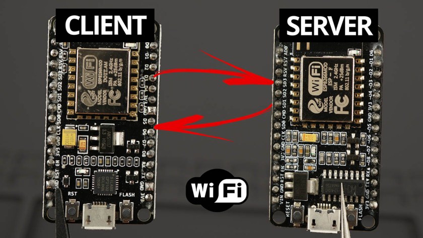
Create an HTTP communication between two ESP8266 NodeMCU boards to exchange data via Wi-Fi without an internet connection. Program your ESP8266 with Arduino IDE.
north stream
I'm not sure send_P() supports sending integers
wintry berry
and I commented out everything related to the temperature sensor
north stream
That example converts numbers to C++ Strings and then converts those to C strings, so you could do it that way: ```arduino
request->send_P(200, "text/plain", String(digitalRead(1)).c_str());
I think that will either send "0" and "1" strings or perhaps "True" or "False" (depending on how String() converts boolean values)
wintry berry
I'm trying to flash it..
north stream
You could also skip all those conversions by using a ternary operator: arduino request->send_P(200, "text/plain", digitalRead(1) ? "1" : "0");
wintry berry
and then I can replace the "1" : "0" with other text like "ON" : "OFF" ?
north stream
Yes, that's an advantage of doing it that way
You can send whatever pair of strings you like
wintry berry
I was able to flash the fist line, but the receiver didn't show anything, now I'm trying to flash the other line.
I got this error
error: espcomm_upload_mem failed
I try to reconnect it to the usb and flash again, and it seam to flash it, but the receiver don't seams to like it 😩
north stream
Time for debugging. The example you posted seemed to try to stand up a server that would respond to specific requests, but what you're describing is different, more like a data link.
I'd probably use print debugging and have the receiver print out whenever it receives anything, then print out how many bytes it got, and then print out what those bytes are
wintry berry
mmm let me see
 wanton bramble
hello. Im an arduino novice and learning how to use i2c right now. Im unsure how I should store bytes I receive from Wire.read(). the read() documenation page says in returns a byte but the example code stores it as a char. other examples i've seen stores it as an int or in an array. this has made me a little confused. shouldnt i just stoore it as a byte?
cedar mountain
It's up to you. If the data are printable characters that you're going to output over a serial port, then char might make the best sense. If it's a number you're going to calculate with, then perhaps an int. If it's binary data, then maybe byte is best. From the computer's perspective they're all just types of numbers, so it doesn't make much difference in many cases.
wanton bramble
thanks for responding. if i choose to store it as an int, will that binary number be converted to a base 10 number than? i'm confused as to how int would handle receiving a byte
cedar mountain
For the most part, all numbers are binary in a computer. They just get converted to and from decimal when they get typed or printed. A byte is just a number that can hold a 0-255 value, whereas an int can handle negative and somewhat larger numbers too.
wanton bramble
@cedar mountain ah okay I see. So if I were to print a byte I would also see a base 10 number like I would with an int? And from what I've gathered a byte is just a 8 bit number and int is a 16 bit number that includes negatives?
north stream
It depends on how you print it: the Serial.print() routines take an optional argument for the base in which to print.
wanton bramble
oh wow i didnt know that, ty
north stream
There are a bunch of nifty features that are ... non-obvious
 twilit hare
So... I'm thinking of doing something either really creative, or absolutely stupid. I want to add software serial to my PyPortal (arduino) so that I can add a second TFT. There are only two exposed pins on the PyPortal.... but there are pads for SWDIO and SWCLK. I took a peek at the variant.cpp file... add it looks like there's commented out code to add those pins as GPIO. Anyone ever try this? Is it even possible, or advisable? I posted a question in the adafruit forum to track the question and answer. https://forums.adafruit.com/viewtopic.php?f=62&t=166968
north stream
I think those signals are used to load the initial software onto the board, or reload it if it gets bricked. They can also be used by debuggers. But perhaps if you don't need any of that, you might be able to use them as GPIO.
twilit hare
Thanks @north stream. I don't need them for day-to-day function. I'm a little afraid that incorrectly changing the cpp will irreversibly brick the device. That being said, sometimes trying and failing is better than not trying at all...
north stream
It is a bit of a nervewracking thing to do: I hacked up the memory map and pin description of one device and I was really worried I was going to ruin something. It worked fine, but it took me a bit to get ready to hit the "enter" key to load the code built with the hacked-up system.
The first time I did that (turning off the fuses for the master reset pin), I was nervous, but less so, because that chip had a "high voltage" programming mode where you could get its attention and reload it anyway. I suspect there's a way to put the Pyportal CPU back into an initial load mode too.
twilit hare
Maybe I'll try it with an ItsyBitsyM4 first.... it's not exactly the same, but it's similar (and a lot cheaper if I break it)
north stream
Good idea.
 pearl fog
Anyone able to spare me a moment? I have a project I'm trying to work on and I need to get the DC motor to work, but it's not working at the moment.
I need a bit of help with adjusting the code first to support a servo motor and maybe with checking the circuitry if that's okay.
(is this the wrong place to send this)
cedar mountain
To clarify, do you have a DC motor (brushed, just runs forward or backward when given power) or do you have a servo motor (takes a pulse-width signal to control position or velocity)?
pearl fog
Sorry, I was tired, it's a DC motor
cedar mountain
Okay, so how are you using the PWM output? Do you have an external H-bridge or FET or something that's driving the motor?
pearl fog
Sorry, I'm slightly confused, I'm pretty new to Arduino coding so I'm unsure what you mean 😅
cedar mountain
The code you shows appears to read an analog voltage from a potentiometer and use that to output a variable-duty-cycle PWM signal on pin 5. I'm trying to understand how that might translate into controlling a motor.
Perhaps you can ask what help you actually need?
pearl fog
I'm not exactly sure how to explain it? I'm setting it up based off of a book I have for learning the basics of Arduino. First it made me make a circuit and coding for a dimmer light, then it said that after adjusting the circuit I could use the same code to make a DC motor work. (if that makes sense)
cedar mountain
Gotcha. Let me explain what I think is going on, and see if that helps...
The analogWrite() call creates what's called a pulse-width-modulated (PWM) signal. It toggles the pin on and off really fast with a given proportion of on and off. So if you feed it to a LED, it averages out to be brighter or dimmer.
A DC motor will run at a given speed if you give it power (voltage). In a similar way, if you turn the motor off and on really fast with a set proportion of on and off, it'll run at faster or slower speeds, essentially averaging out the voltage.
However, while a LED is a low-power device, which the Arduino can light up just from one of its pins, a motor is generally higher power. So to do this, you need some extra circuitry to take the on-off signal and act as a high-power switch to control the voltage to the motor. This would be something like a transistor, or a circuit like the H-bridge that I mentioned.
pearl fog
I see..
cedar mountain
There are Arduino shields and boards designed to do this sort of thing, for instance.
pearl fog
Since I don't understand that, and have never heard of Arduino shields (yet), I'll just state that I use an Arduino Uno for my circuitry.
cedar mountain
A "shield" is a board which plugs on top of the Uno and provides additional capabilities. For instance: https://store.arduino.cc/usa/arduino-motor-shield-rev3
The shield is based on the L298, which is a dual full-bridge driver designed to drive inductive loads such as relays, solenoids, DC and stepping motors.
pearl fog
So that's what they're called... I don't have access to one at the current moment.
cedar mountain
Gotcha. Well, there are potentially lots of options depending on what you have available and what you want to get working.
pearl fog
Should I send a list of what I think I should be using? (or not..?)
cedar mountain
Sure. Perhaps this is more appropriate for #help-with-projects , if you're looking for overall design advice rather than Arduino coding specifics.
pearl fog
Alright then, thanks!
 pine bramble
hii, could someone help me about the esp01
i bought one from aliexpress and i dont know if it needs any configuration before working
pine bramble
hi i am going to make a project which is when i press one of my buttons my led will turn up but when i press another button its going to close my led what ohm resistors should i use
 forest hawk
if you dont mind burning some leds over time, you can connect them straight into arduino, no problem
leds just need resistors when making big projects that are going to be turned on for a long time
candid topaz
Use this LED resistor calculator to find out the suitable resistance for your LED circuit consisting one or more LEDs.
forest hawk
nice
 cobalt mirage
Does anyone know a place where they sell cheap Arduino parts?
I don't like amazon, they are quite expensive
cedar mountain
AliExpress?
 weak walrus
My TFT screen went white after weeks of using it 😦
Any ideas on what it could be? I tried swapping out the wires...
I don't think its a soldering issue but I dont have a multimeter
north stream
anyone knows why my RGB isn't working? https://hatebin.com/zipundleat
For cheap Arduino parts, I look to Seeedstudio and Electronics Goldmine
Maybe try digitalWrite() instead of analogWrite()?
Maybe try digitalWrite() instead of analogWrite()?
@north stream me?
Yes.
okay
@north stream it didn't work
weak walrus
(mine was a software issue :p)
north stream
and i have another qustion
can you tell if this RGB is common cathode or anode?
No, you'd need to test it to find out.
okay
and i changed it to digitalWrite and it didnt work
@north stream do you think I should try digitalRead?
No, digitalWrite() is correct.
Okay
What should I do then?
Perhaps your LED is miswired? Does it work when hooked up by itself with current limiting resistors?
What do you mean
Have you tried just hooking the LED to power with current limiting resistors to see if it lights up?
i dont get what you mean
I see you have an LED. Have you tested it?
I’m using an Rgb
I don't understand.
im not using an led
im using an rgb
I'm guessing you mean an RGB LED. There are a few kinds of RGB LEDs.
yes
im using rgb led
Call? What call?
It looks like you posted a picture of it above.
yes
this is my rgb
That is likely one of 4 kinds of LEDs. The most likely are 1) discrete common cathode or 2) discrete common anode. However other possibilities are addressible LEDs, 3) NeoPixel style asynchronous, or 4) DotStar style synchronous. I cannot tell by looking at a picture, the best way to find out is by looking at the data sheet (if you have a data sheet for it), or testing it (if you do not have a data sheet for it).
i think its a common anode
or common cathode
i dont think its any of the others
and most likely its anode
They way to find out is to measure it (if you have a meter with a diode test function) or test it with a current limiting resistor and your Arduino as a power supply (if you don't have a meter)
yep its anode
In that case, you would hook the (common) anode to the power supply (such as the 5V pin on your Arduino), then hook each cathode to an I/O pin with a current limiting resistor, and use digitalWrite() with a LOW argument to turn on that color.
i though HIGH is on and LOW is off
With a common cathode LED, you pull the (individual) anodes positive to light them. With a common anode LED (such as yours), you pull the (individual) cathodes negative to light them.
i dont understand what you mean
Different kinds of LEDs are controlled in different ways. For your LED, a low signal lights it by providing a voltage difference between the anode (which is at a positive voltage) and cathode.
yah
when i tested them on the 5 volts it worked
but not with gnd
Some LEDs are brighter than others: the brightness is controlled by the current (and duty cycle, but we're not going into that right now), and the current is controlled by the current limiting resistor.
its bright i just needed to fix the way of one of the resistors
actually my dad's going to help me
and thanks for trying
 river osprey
I'm trying to use adafruit_imagereader to display images using a bluefruit + tft gizmo. Problem is, I want to display some animations, and I need to do it frame-by-frame and a 240x240 pixel 24-bit color BMP is pretty sizable, so i don't have enough memory to store all the images. Is there a better library for displaying images that supports 4 or 8 bit bmp?
sadly I attempted to use arcada, but it conflicts with the TFT loading that i'm using (I am also piggy-backing off of the bluefruit example of streaming a picture from your phone via bluetooth)
also arcada isn't supported by the bluefruit CPX
river osprey
I have imagereader 2.3.6 which seems to be the latest, but it won't load 8 or 16 color BMPs... Or at least, the ones I created from a source (24bit which loaded fine) didn't work. I used imagemagic and just set -colors 16 etc
magick convert swirl1240.bmp -colors 16 BMP3:swirl240_16.bmp
river osprey
it really seems to be the format of the BMP. there is some setting that isn't letting it work. What confuses me the most is that the blinka BMP which is 2 bit color, works fine, but when I attempt to convert and rework the color space using -colors or -depth the images will not load 😦
 topaz compass
If it's a format issue, have you tried BMP2 or 4?
red vale
Hello is anyone willing to collaborate on an arduino project message me if you are intersted
river osprey
@topaz compass thanks for the suggestion, i'll give it a try, although all the example BMPs are BMP3... it's worth a shot though
 plucky oracle
hello please i need a software simulator for arduino with crack
help me please guys
can someone send me the software please
 tidal sonnet
Anyeone know how MA845X is different from MA8451?
topaz compass
@plucky oracle You should not show the world you are a thief.
plucky oracle
@topaz compass so buy me the professional version
 stray basin
Hello, having difficulty blinking an external led.
Trying to blink the external led simultaneously with the built-in on an ESP2866 (d1 mini) and can't figure out how to wire it so
I am also trying with an Arduino nano but also can't get the external led blinking. At least on the arduino The led comes and stays on. On the d1 mini I can't even get it to light uo
lone ferry
@stray basin Can you share the code?
stray basin
tried like this https://www.arduino.cc/en/uploads/Tutorial/ExampleCircuit_bb.png
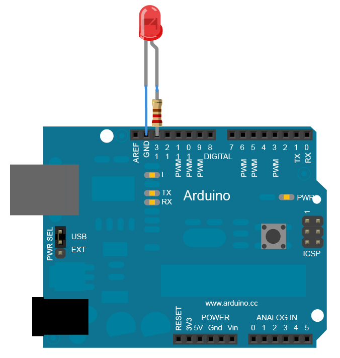
@lone ferry it is the blink sample code: https://www.arduino.cc/en/tutorial/blink
Open-source electronic prototyping platform enabling users to create interactive electronic objects.
lone ferry
Did you use the exact same code?
lone ferry
Are you sure you hooked it up to pin 13?
stray basin
Oops I was off by one pin it was going to 3v instead. Thanks!
Now I can't figure out why the same doesn't work for the ESP d1 mini.
Should be similar wiring?
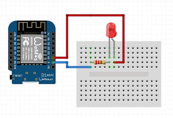
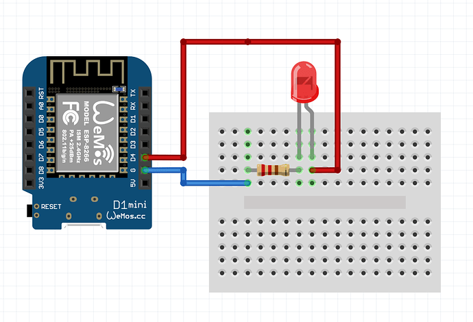 lone ferry
You may have the LED the wrong way around there?
If you're using the same breadboard, notice that in the ESP schematic the resistor is after the LED and in the Arduino schematic it's before.
This doesn't really matter, but it may be causing you to have the wires switched.
stray basin
Thanks again, I had a closer look and my header pins were not soldered completely on the d1 mini. The only thing is on the d1 mini the external led is opposite it turns on when the built in one turns off.
stray basin
Working now, wired the cathode to d4 and the anode to 3v
north stream
\
You may need pull-up resistors.
@north stream how do i put it?
from where to where
Hook a 4.7kΩ resistor from SCL to +5V and another 4.7kΩ resistor from SDA to +5V.
do i use a wire to connect the resistor?
I don't know anything about your setup, so I can't say. A wire isn't strictly required, but you may need one depending on how you've connected things.
then isn't soldering it the best way?
or what do you think is the best way?
Hook a 4.7kΩ resistor from SCL to +5V and another 4.7kΩ resistor from SDA to +5V.
@north stream and isn't VCC for +5V?
The best way depends on what you have (like if you have a breadboard between the Arduino and display or not, etc.)
And Vcc is generally 5V for an Arduino, yes. I think the pin is marked "5V", which is why I used that term, but boards vary and my memory isn't perfect.
i dont understand what you mean
You said "and isn't VCC for +5V?", I was just replying to that.
I'm using Arduino Uno
Hello, I'm trying to use my I2C LCD. I connected it from the following link https://www.makerguides.com/character-i2c-lcd-arduino-tutorial/ I then ran the address scanner code from the same link. I fortunately I keep getting:
Scanning...
No I2C devices found. Any suggestions?

In this tutorial you will learn how to control a 16x2 or 20x4 I2C character LCD with Arduino. Wiring diagram and many example codes included!
north stream
can someone please help me?
odd fjord
@north stream how did you make the connections -- can you post a picture showing the wiriing?
north stream
@north stream how did you make the connections -- can you post a picture showing the wiriing?
@odd fjord can you call cause thats my only way to use camera?
odd fjord
sorry -- I'm not interested in calling -- be happy to help via chat.
north stream
were is that @odd fjord
odd fjord
this channel, I meant
north stream
and how am i supposed to show you the wiring?
odd fjord
Sorry -- that is not my problem 😉 how did you make the connections?
odd fjord
does the LCD board have header pins? did you use jumper cables?
north stream
what do you mean?
odd fjord
what did you use to connect them?
north stream
wires
odd fjord
so you stripped insulation from the wires and put them in the headers on the UNO? How are they connected to the LCD?
north stream
so you stripped insulation from the wires and put them in the headers on the UNO? How are they connected to the LCD?
@odd fjord you can see the photos
odd fjord
yes -- looking at them
north stream
okay
odd fjord
I don't see anything wrong
north stream
Those pins at the far end of the daughterboard look like they might be touching each other (they probably shouldn't), and there's something sticking out from under the LCD board (meaning it might be physically damaged)
idk whats the problem
It's also possible that the daughterboard doesn't include I2C pull-up resistors.
okay
so whats the solution?
First, try bending those pins so they don't touch each other.
Okay
is this the thing you mean is sticking out @north stream?
First, try bending those pins so they don't touch each other.
@north stream which pins?
the yellow wires?
 proper tree
the 2 on the black board, furthest from the connectors?
north stream
the 2 on the black board, furthest from the connectors?
@proper tree me?
i have no 2 black wires
proper tree
the black board
north stream
what board?
proper tree
north stream
okay
 trail garden
i started getting this kind of error
../Documents/Arduino/libraries/Adafruit_Keypad/Adafruit_Keypad_Ringbuffer.h:57:5: note: type 'struct Adafruit_Keypad_Ringbuffer' should match type 'struct Adafruit_Keypad_Ringbuffer'
     Adafruit_Keypad_Ringbuffer;
     ^
Sketch uses 7150 bytes (24%) of program storage space. Maximum is 28672 bytes.
Global variables use 338 bytes (13%) of dynamic memory, leaving 2222 bytes for local variables. Maximum is 2560 bytes.
am i missing something, using Adafruit_Keypad.h and Keyboard.h - at started having this error, does not even work with example keypad_test file
 sonic plank
Anyone know about a tutorial for making 10k potentiometer reading into custums values?
Onto a lcd, also need help to do a /if 2 values are equal make a light turn on in a if command type
north stream
There's a nice tutorial here https://learn.adafruit.com/adafruit-arduino-lesson-8-analog-inputs/variable-resistors-pots
 north stream
anyone knows why my buzzer isnt working?
code
Try having a single loop that alternates the pin between 1 and 0: the current code sets it to 1 a thousand times then sets it to 0 a thousand times. What you want to do is go back and forth.
yes
like this
Try having a single loop that alternates the pin between 1 and 0: the current code sets it to 1 a thousand times then sets it to 0 a thousand times. What you want to do is go back and forth.
@north stream what do you mean?
?
Anyone knows why my buzzer isn’t working?
Code
sonic plank
Have you testet if the buzzer works?
north stream
sorry
sonic plank
What?
 fringe stag
Hello I have an Adafruit Trinket M0 that I'd like to use as a keyboard, does anyone know which keyboard library works for this? Is the Adafruit Pro Trinket library the one? Thank you!
north stream
@north stream something like ```arduino
void loop() {
digitalWrite(buzzerpin, HIGH);
delay(1);
digitalWrite(buzzerpin, LOW);
delay(1);
}
@north stream okau
and anyway it worked
but still, thanks
undone harbor
By chance does anyone know if there exist a HAT or board which pairs the pins from the Feather to an Arduino HAT pins?
 opal ivy
If a new sensor/module comes in for arduino/raspberry pi how does one knows how to write code for it?
odd fjord
@opal ivy There is usually an accompanying library with examples and a guide.
opal ivy
@odd fjord where can I usually find that?
odd fjord
for Adafruit products it would be in the Learning guides. https://learn.adafruit.com -- what sensor are looking for?
otherwise in Arduino, you can use the library manager to see if you can find a library for the sensor then after installing it, see if it has examples....
opal ivy
Thank you @odd fjord
north stream
@undone harbor yes https://hackaday.io/project/169154-feather-r3-adapter
undone harbor
@undone harbor yes https://hackaday.io/project/169154-feather-r3-adapter
@north stream That is exactly what I am in search of, Much Thanks... so am I correct that I can download the 2 PCB files and have them made on my own or do I have to pay for the files?
north stream
I think you can just download them and get them fabricated. Or check the usual PCB vendors and see if someone already offers it as a project you can buy.
undone harbor
ok thanks again
 thorn relic
why is it people always use const int to define static things like pins instead of just using #define
ah I see, because define has global scope
lone ferry
And const int is less error-prone, plus it makes things easier for the compiler to reason about.
thorn relic
how is it less error prone?
lone ferry
You can write wrong things in a #define . For example #define min(a, b) a < b ? a : b. This looks correct but it can break.
And this creates subtle errors in your code that can be hard to find.
Or something like #define X 123;
 sturdy bobcat
The #define dates back to the first version of C. const int happened much much later, when compilers didn't need to fit into 64k of RAM.
 open wave
hi guys. i have some problems with my relay. i am using the sample LED code just in case but the relay does not work here are some pics of my connections
if you need more pics pls just tell me
when i try and short those wires
my fan turns on
the fan that is connected to the relay
when i put an LED on pin 13 it turns on
i tried on another relay but still did not work
cedar mountain
Relays generally require a decent amount of current to energize their coils, possibly more than the Arduino can supply with a GPIO pin. Do you have a spec for the relay you're using?
cedar mountain
That specifies a coil power of 0.36/0.45W, which at 5V would be 72/90mA. An Arduino pin is usually 40mA max, so it couldn't directly drive the relay. It looks like there may be some extra circuitry on the relay board, possibly some helper transistors or something, though, so I'm not sure whether it's designed for logic-level inputs.
open wave
so wut should i do
connect an external power source for the 5v pin??
from a year i think i used my other relay
tried connecting that today but still did not work
lemme see specs for other relay
cedar mountain
Personally my next step would be to consult the documentation for the relay board you have to see what it expects as input. But that's my sort of approach... you may be more of a "try something and see" person, heh heh.
open wave
yeah lol
i do not know how to find it lol
the documentation
and the relay is from a year
so
yeah
lol
 rancid zinc
I have a 3.3v compatible arduino, and i need to shift the digital outputs to 5 volt, but also shift the inputs down to 3.3v, im gonna use it for controlling synthesizers so there could be long cables, would this schematic work?
north stream
The diodes will have a lot of drop, and won't let the 5V signal drive the inputs low, nor let the 3.3V signals drive the 5V signals low.
rancid zinc
Ok, thx, any suggestions how to do it?
north stream
I think you only need one converter, but you'll have to figure out when you're sending and when you're receiving, and use that to control the DIR pin.
pine bramble
anyone avail to help me make a circuit to switch 7 diffrent steppers frmo one button push. ?(so i can use one stepper chip to chose which motor to run ?
anyone on here good with circut design ? i need a circut that when you press a button for a period of time that it selects one of 7 sets of plugs ( 4 wires only 2 need switched as a pair on the plug.. one input 7 possible outputs. for each 1 second button pressed it selects each plug ( first one is one second second one is 2 seconds etc ( adjustable would be nice for speed later) button is just a momentary swittch like an endstop
and an led on each position to show which is being selected and also one to light while button is pressed.. .... whats teh easiest way to make this. .? i knwo how to make a rotary switch to do this but i want a little pcb board to do this in the end..... its for a 3d printing project for a printer mod
 strange grove
I have a 3V UART signal from my Oxygen sensor.
I tried hooking up to an available UART pin (Serial 1/2/3) on the Adafruit Grand Central Beta board but I am not getting the right message on my serial monitor (Serial 0).
What’s interesting is that, it worked when I used the same code for Arduino MEGA2560 but level shifting the 3V output of the Oxygen sensor to 5V before connecting to the MEGA.
What’s wrong with Adafruit Grand Central not reading the serial data?
 robust flint
um...i am new to coding
can i ask a question about my Arduino code here?
just would like some help fixing it
stuck coral
Just post the question, no need to ask
robust flint
can i post images of the code?
sorry i just joined the server and am not aware of the rules
is why
stuck coral
Post either a pastebin or format it correctly in discord
As an example... use three `s
hi, the main idea of my code is to get the time duration taken for the robot to move from point A and get to an obstacle placed in point B( sensor input would prompt obstacle avoidance) and then to turn to another row of grass and move that same distance...the idea here is to make the time duration flexible so that it can be used on a variety of fields, i saw some code online where they used the "millis" command to do something slightly similar but i am not a coding expert(this is the first code i have ever written at all). i definitely did something wrong because i am getting error "duration was not declared in this scope" . i think i coded it so that the millis at the start in point A the millis at the end of when it reaches point B would be minused so that the time taken to make the journey would be recorded but i am getting errors so i would like for someone who knows how to code to help me out.
stuck coral
Please either format it correctly, or create a pastebin https://paste.ubuntu.com/
I would delete that
robust flint
sorry
stuck coral
Its alright
robust flint
so i should send a link right?
stuck coral
Yes
stuck coral
Yes, so your duration issue is because you are trying to use duration, but it is not in the scope. If you declare it within setup(), then no function outside of setup() can use it
So you should make it a global variable in this case
That way loop() can access it
stuck coral
You did it with in1, in2, in3, and in4
robust flint
thats the problem..i did that too but then it will ask for "timeend" and "timebegin" to be declared too i think
and if i do that will they have the millis values i want them to have?
stuck coral
Those will also need to be global if you organize your code that way, and if you set a global value in one function, it will be that value from any other function
robust flint
do you understand what i am trying to do though? with the duration and the millis thing
i wanted to ask if you know a better way to do it
stuck coral
I think so, looks like you could learn some code organization
And I see you're not using timebegin and timeend in loop(), you dont need to make those global, and to save you a byte of memory or two you dont need to delcare timeend you can - unsigned long duration = millis() - timebegin;
robust flint
forgive me if i am a bit slow to understand
ok but....if i change line 36 to your suggestion and remove line 35 and make duration a global variable ....is this "unsigned long duration = millis() - timebegin" what i should declare it to be?
stuck coral
You would declare duration around your in variables outside of all the functions, then change 36 to be duration = millis() - timebegin;
robust flint
ok please tell me exactly how you would declare duration globally...i mean what you would type
i just now reasoned that since there are no instructions before line 23 i could just make duration= millis() but i want the time value to be exactly at the end of line 33, with that being said i dont know if declaring duration to be millis() globally would alter this value
cedar mountain
The value of the time will be captured at the point the line is reached and the millis() function is called.
stuck coral
just unsigned long duration;, you can then set it anywhere in code.
Maybe give it a default value unsigned long duration = 0;
robust flint
The value of the time will be captured at the point the line is reached and the
millis()function is called.
@cedar mountain just to clarify...this means i am safe to declare duration = millis() globally right?
sorry for the tag
stuck coral
No
robust flint
@stuck coral thank you....sorry for the tag
cedar mountain
If you do that, its value will be whatever millis() returns at the start of the program.
stuck coral
Even then, wont the timer not be initalized yet @cedar mountain?
I thought you cant use millis() before the function before setup is called
cedar mountain
That's a good point, thank you. Yeah, it's a bad idea for several reasons.
robust flint
.....
stuck coral
Just declare duration next to your in variables, and on line 36 set it to millis like how you are now just to get rid of the compiler error
stuck coral
Sure, then you know its value from the start
 obtuse spruce
Long shot - but anyone here ever try to do what CircuitPython does, and present the onboard SPI flash as a USB drive, while at the same time reading files off of it?
stuck coral
Well CP is interpreted @obtuse spruce , running a compiled applciation from flash would require overwriting progmem unless the issue with QSPI code execution was fixed
CP interpres the file from the flash, with the actual executable in progmem along with the UF2 bootloader.
Oh I misread that
I think
Do you mean to run code, or just file storage?
obtuse spruce
I'm not being clear: I'm coding in C++ - and I'm trying to have my device do the same technique that CircuitPython does w.r.t. to files.
I want to allow the user to plug the Feather M0 Express into a computer and just drag files over to it. Then my app on the device will read those files and do something with them (so, for example, use those as input to a music generation program)
But I'm only asking about the interesting arrangement of using both the MSC support from TinyUSB and the SDFat support -- both at the same time using the Express' on-board SPI flash chip.
CircuitPython achieves this... and I have it somewhat working... but there are problems in my version.
stuck coral
Ah, I have not seen that, I imagine the issue is the seperation of your code reading from storage to say make music vs the USB FS.
obtuse spruce
Well, the issue is that if I write a file larger than 64k, then the file as stored in the on-board flash is corrupted.
stuck coral
Well it should never be written to program memory, only a RAM buffer before being written to the QSPI flash
obtuse spruce
I can't tell if this is a problem with SDFat's FAT12 support, or a race condition between MSC and SDFat...
yes - program memory isn't involved here at all
stuck coral
I have had many issues with SDFat FAT12, but I couldnt really tell you without digging in and Im going to sleep soon
obtuse spruce
on-board = on the Feather board, no the on-microncontroller
obtuse spruce
I think 256...
But, Adafruit_SPIFlash has support for SDFat - and handles the mis-match in page size
stuck coral
I was thinking about the write operations, because 64K is ringing a bell in my head with those flash ICs
obtuse spruce
Hmmmm... okay... good to know
stuck coral
Blocks are 64K
obtuse spruce
well, I'm heading to bed too - so if something pops into your brain... I'm generally logged in here.
stuck coral
I gotta go to sleep, but I would read the datasheet for the IC concenring blocks, they are 64K long and when I was making a OTAU bootloader I remember something about not being able to write to two blocks at the same time in an operation, or they need to be erased before hand, something like that
I would find it quite a conquendense it picks 64K as a number for a race condition or memory issue
 umbral wasp
hi, I'm trying to display a logo (8px * 10px) as well as a centered text (30px) except that the text is only displayed on a plate (I have 5 plates of 8 * 8)
or sometime text no appear
north stream
Seems like an addressing or timing problem, but we'd need to know more about your setup to offer specific advice.
 sterile niche
hey, do you think I buy a kit from the website?
open wave
can i run a LED strip that has 60 leds with a 5v 4amp power brick
cedar mountain
The typical NeoPixel is 60mA at full brightness, so 60 of them would be 3.6A maximum. You should be good if it's that kind of strip.
open wave
ok
it is
thanks
obtuse spruce
Well - this has been a very interesting few hours of debugging......
SO - I'm getting spurious data errors reading the flash chip on a Feather M0 Express
as in out of about 200k of data read, I see between 0 and 10 or so read errors - that is, the wrong data is read back.
I think it is always a 1 read back as a 0
resetting my program and reading the blocks a second time results in errors in different blocks - so I'm pretty sure that the data is written to the flash correctly - just not being read right all the time
stuck coral
Are you using SDFat to do this read test or are you reading directly?
obtuse spruce
reading directly using Adafruit_SPIFlash::readBuffer -- for this test I've cut out the SDFat code and the MSC code
and reading just 512 byte blocks
(which is what MSC would do - hence that size)
stuck coral
Hm, sounds like you're about to find something quite interesting.
obtuse spruce
Perhaps.... 😫
stuck coral
I feel you're pain. So you're writing 200K of a specific byte then reading it back?
cedar mountain
Any chance the SPI clock phase is wrong? You might be getting bits on the edge of a transition.
obtuse spruce
well... this is just the SPI flash chip that is part of the Feather M0 Express board.... and using the standard Adafruit SPIFlash library.... so, er... assuming that SPI clock phase and other particulars is correct....
I'm writing 512 blocks with a fixed "magic" header and a pseudo random sequence - so that I can test that the data came back the same - and have a good "random" distribution of bits, and word patterns.....
The magic header just identifies these blocks from any other data on the flash chip
 snow pier
Someone made experiences with the at-09 ble module?
obtuse spruce
I'm about to write a small self contained sketch to demonstrate the issue... and I'm off in search of some other M0 Expresses I might have lying around to see if it just this board (which I is like brand spanking new...)
stuck coral
Yep, if you can recreate on another board, it is a library issue, and I have been having data corruption issues eevry once in a while with a M0 board + SPI flash w/ SDFat so Im interested if you figure it out.
Does changing the SPI clock phase do anything as ed recommended?
obtuse spruce
Well - SPI clock phase is something deep in the library, no? I wasn't planning on diving in that far ... yet ....
stuck coral
Okay, well in src/spi/Adafruit_FlashTransport_SPI.cpp you can set SPISettings in the top functions just to save you a tiny bit of digging
Line 46 you can set a phase
obtuse spruce
okay - I'll do that after I have my "minimal" tester sketch written.... currently I have stuff splatted all over my main project's code with tons of things #if 0'd out
open wave
i know i am stupid
i plugged in a 19v 6.3a power brick into my arduino uno and i saw a tiny flame somewhere and the arduino is dead
is that supposed to happen
thorn relic
Its probably just the LDO regulator. It will probably still power off USB or 5V directly
Ive also done this 😁
thorn relic
makes a nice repair project if you grab some replacement AMS1117v5 which is probably whats got a nice hole in it
south pulsar
when i plug my computer into my arduino nano (via usb) then COM3 (the port im using) only shows up in the device manager for a half second, and then disappears right after
open wave
wut programmer for arduino uno
north stream
Normally the Arduino Uno has its own bootloader to program it, so you don't usually need a separate programmer. Or are you asking about the development environment?
obtuse spruce
Okay - current status: Seems that this whole flash issue is just this one Feather M0 Express board... The other one I have verifies data perfectly every time.
north stream
Normally the Arduino comes with a bootloader, so you don't need to burn one. If you do need to burn a bootloader, I think you'd need an "ISP" programmer, but there is a way to use a second Arduino to do that.
stuck coral
Well ig thats good @obtuse spruce, do you still run into the first issue you were having?
open wave
@north stream so wut do i do now
obtuse spruce
No - everything is explained by this: reading from this flash chip gives a very low, but consistent set of bit errors - always a 1 read as a 0
obtuse spruce
@stuck coral --- you mean this line: _setting = SPISettings(clock_hz, MSBFIRST, SPI_MODE0);
I don't see a phase parameter there
stuck coral
SPI_MODE0 sets a clock phase and another setting
obtuse spruce
oh - I see MODE0, 1, 2, 3 (amusingly, set to values 2, 0, 3, and 1!!!)
but SPI.h gives no clue about phase
stuck coral
The Serial Peripheral Interface (SPI) is a synchronous serial communication interface specification used for short-distance communication, primarily in embedded systems. The interface was developed by Motorola in the mid-1980s and has become a de facto standard. Typical applic...
Too bad they dont explain in comments
obtuse spruce
okay -but given that the library from Adafruit uses Mode0 - and that works on another board - and it mostly works on this board ---- is there a reason to expect that changing the phase will improve things?
I'd assume that if the phase was wrong - everything would be broken
stuck coral
Not always, sometimes if you see a few rando bitflips then it can be. I had this issue with a high speed ADC last week.
But it seems to be a board issue in your case ig
proper tree
Super Goku!!!!! The Smoke and Fire are what make electronics run!!!!! You cant just let them out!!!!
 cedar flume
I want to controll an LED Strip with Arduino.
I have seen 5V and 12V Strips.
Are the 12V have brighter light or what is the difference?
north stream
Basically the 12V ones have more voltage headroom (so you don't need to work as hard to power long ones) but they're less efficient.
 halcyon cloud
how to use tiny go with arduino on mac and tutorials
stuck coral
If you are using tinygo you should look at their website https://tinygo.org/usage/basic/ although note this channel is more centered around the arduino framework which is not used with tinygo, however it obviosuly supports some arduino boards
Everything you need should be there, inclduing setup on a mac https://tinygo.org/getting-started/macos/
sterile niche
hey, do you think I buy a kit from the website?
snow pier
Ive got a problem with the AT-09 BLE module. (Its a HM-10 fake)
I dont get response when i send AT-commands over the serial monitor.
When i write the commands into the code, it works, more or less.
I can change the name and the role but i cant set a password.
Any suggestions?
obtuse spruce
@stuck coral - thought you'd want to know - reducing the SPI clock rate by a factor of 4 (from 48MHz to 12MHz) - results in zero errors. And this was reading data written to the flash at the original high rate.
stuck coral
Hm, does changing the phase do anything at all at the origonal speed to help? Becuase that would be another sign of a potential phase issue, as there is more time for rising and settling.
But very interesting, thank you
obtuse spruce
I'd have to go modify the guts of the library to test that.... perhaps later I'll try that... but for now..... Onward!
And now that my "multi-flash" flash station project works - I think I'll try to show that on show-n-tell tonight.... seems like a useful thing people might want.
stuck coral
Awesome! Lol, kinda fell asleep there 😬
 slim cloak
Trying to download Arcadia library for the Clue and it says there are dependencies missing. I'm lost. Seems like its missing basic libraries. Have the lastest IDE. Is there anything that goes before this? Working off the guide. The clue itself is working and download the blink program successfully.
stuck coral
What is your compiler error?
slim cloak
No error just setting up the libraries as the guide say. Arcadia will not install.
stuck coral
Well without an error message of any kind its hard for me to help
slim cloak
Just the setup. it's a new laptop. Downloaded the IDE and loaded some drivers. It gave me list of dependencies that were not installed. It seems like a basic list of functional libraries.
stuck coral
When it gives you the list, what does it say? Could you give me that output? I assume you need Adafruit_GFX, Adafruit_SPITFT, and Adafruit_NeoPixel
slim cloak
Yes thats the list
stuck coral
Well go install those libraries from the library manager and report back
slim cloak
It's a huge list. That's why I wondered if I missed a basic download.
stuck coral
Again, if you could paste in the output that would be more helpful
slim cloak
Can't paste it. Runs off the screen. I am making headway. I see it will download other dependencies so it probably won't be so bad.
stuck coral
In cases like that, and when you want to place code, you can either format or make a pastebin just for future reference
slim cloak
Thanks IoTPanic. I was able to download what I needed and it works fine. It seems that a number of the libraries listed were already installed. The Arcadia warning went away so it must have them all. I was able to reload the sample program the Clue came with so all is good. Now to tackle circuit python.
twilit hare
has anyone ever successfully transferred an image to an M4+ESP32 combo over MQTT (using BASE64)? I can't find any examples.... not sure if it's possible. [Note: I can easily download images over HTTP, but really want to transfer the images over MQTT... even if that means breaking up the encoded message into parts and assembling before displaying the image]
candid topaz
you can send text to topic "begin" and concat base64 decoded parts to array till you get text "end"
@twilit hare
on "begin" clean array, on message - append to array, on "end" - display that array
stuck coral
@twilit hare Im not sure I agree, I would fragment the image in the M4, sending the data to the ESP32 in byte for over serial or SPI and use the ESP32 just as a network controller but thats just me.
pine bramble
Hi Everyone,
I got a little problem trying to make my new NeoTrellis working with Arduino. I followed step by step the guide on the website but i keep having this error popin up
Library/Arduino15/packages/arduino/tools/arm-none-eabi-gcc/7-2017q4/bin/arm-none-eabi-g++: no such file or directory
I updated / reinstalled / bords and librairies but nothing is changing.
Do you have any clue what to do?
Thanks 🙂
stuck coral
Have you installed Arduino SAMD support along with the Adafruit SAMD board package?
pine bramble
i did
stuck coral
Not sure then, maybe someone else has an idea because Im pretty sure thats the board support with the arm version of gcc
pine bramble
im sure as well. Maybe i can download that file and put it in the folder myself?
stuck coral
Would not recomend, no, unless someone here recommends it knowing something I dont
candid topaz
@pine bramble https://github.com/eblot/homebrew-armeabi
pine bramble
@candid topaz i will install that and check. Thanks
candid topaz
or maybe this one https://github.com/ARMmbed/homebrew-formulae
@pine bramble maybe 2nd link
twilit hare
@candid topaz and @stuck coral Thanks for your comments. I'll play around with it more tonight (after work)
 quaint dune
Hey there can anyone drop a link for best arduino uno beginner tutorial.I have already joined tinkerCAD
north stream
What's "best" depends on the person, but here's one possibility https://learn.adafruit.com/lesson-0-getting-started
SparkFun also offers some like https://learn.sparkfun.com/tutorials/what-is-an-arduino
pine bramble
or maybe this one https://github.com/ARMmbed/homebrew-formulae
@candid topaz well its not working nether

GitHub
homebrew ("the missing package manager for OS X") formulae from the mbed team. - ARMmbed/homebrew-formulae
slim cloak
On the Clue can you load Arduino and Circuit Python setups just in case you want to switch. If I load an ardunio program for one project and decide to repurpose the clue for Circuit Python would I have to reconfigure the board. Are they mutually exclusive or can the be called as needed?
odd fjord
@slim cloak You can load either an Arduino sketch to the board or Circuitpython. When you load one, it replaces the other so you cant' have both at the same time but you can freely switch back and forth. Note. if you have files on the external Flash as part of CircutiPython (CIRCUITPY drive) they "should" not be impacted by load ing and Adruino sketch. If you go back to CP they should still be there. That said, I would not depend on it. Back them up first..
pine bramble
@candid topaz are you sure it does install on the right folder?
pine bramble
do i need to install these first? brew install arm-none-eabi-llvm
brew install armv7em-cortex-m4f
candid topaz
i checked my taps, i only used armmbed brew recipe
pine bramble
i'm confused 😟
candid topaz
yeah, sometimes get things working on mac is bit challenging 🙂
pine bramble
i guess i will delete and reinstlll all Arduino files...
north stream
At this point, I think that's a logical thing to try: the files you need should be part of those board sets.
upper rune
so i have an arduino pro mini and i am trying to control a ESC with it, i have figured out using pulseIn() that the ESC takes an input between 2000 and 4000 microseconds with the controller i have, but when using the arduino i am unable to replicate the results only getting 20% speed with 1800-2000 microseconds. does anyone know if there is a hard limit on the microseconds using the servo library and how i would overcome this?
north stream
I suspect the servo library is designed for ordinary RC servos that take a 1000-2000µs pulse. Presumably, you could either modify the servo library, or use PWM directly. The PWM approach gives you full control, you'd you have to set the repetition rate appropriately, and convert your pulse lengths to duty cycle.
upper rune
ok, ive been looking around however i cant find the cycle length of analogWrite() or the correlation between duty cycle % and microseconds?
north stream
The pulse width will be the repetition rate times the duty cycle. So if you have a repetition rate of 50Hz, which would be 20ms. A 10% duty cycle would be 10% of 20ms, or 2ms, which in turn is 2000µs.
However, I think the default repetition rate for analogWrite() is much higher (a few hundred hertz, maybe?), and your ESC may not work with that. The servo library does some things to set a higher accuracy and a different repetition rate.
It looks like you can tell the servo library to use a custom minimum and maximum pulse width: this may be an easier way to get the wider range you mentioned. https://github.com/arduino-libraries/Servo/blob/master/src/avr/Servo.cpp#L238
I also see that the servo library interprets values less than 544 as degrees (they get multiplied out to get the microseconds), and larger values as microseconds directly.
cedar mountain
Ooof... I mean, I see why they do it, but invisibly overloading an API like that just sends a shiver up my spine.
upper rune
thanks, i got it to work with some trial and error, do you know if there is a analogWriteResolution() alternative for non due arduino's?
upper rune
where are themes stored?
upper rune
yh
 trim hatch
then once you are there go to lib
the lib folder
then inside there there should be another folder called theme
i need the theme folder
upper rune
upper rune
dw
upper rune
as of right now i am using analogwrite to control an ESC but i am only using 17-33 of the 0-255 that analogwrite can do, is it possible to have 0-255 control 17-33 more precisely, since 16 steps is not very good for my usage?
cedar mountain
You'd probably want to use the Servo library instead, which should give more precise control.
upper rune
OMG, i am soo dumb! i set the proccessor in the IDE to 8MHZ instead of 16 which was messing with my pwm values.
cedar mountain
Ah, yeah, that'd explain it. I was wondering what kind of crazy ESC you had to want those pulse widths...
quaint dune
Are there any beginner projects for arduino ...... I have already done those on sensors like pir, Temperature, photoresistors etc
Can some1 explain how does the led glow when 5V is not attached to the breadboard?
 scarlet sky
@quaint dune When you digitalWrite "HIGH" the Arduino passes the +5v out via the pins you have connected
pine bramble
At this point, I think that's a logical thing to try: the files you need should be part of those board sets.
@north stream @candid topaz after a total reinstall it works. Thanks for your help 😉