#help-with-arduino
1 messages · Page 60 of 1
 hybrid fossil
 reef ravine
the HC-05 is a 3.3v device, it won't tolerate +5v (at least not for long)
hybrid fossil
hes playing around a day, still alive :/ but will warn him
oh that's why he might not get signal, when he disconects pc
reef ravine
all part of learning...
hybrid fossil
from nano,
and when connected to pc, BT works it seems, can it be the part, that he used the Nano Rx and Tx pin
reef ravine
if Tx and Rx are backwards it won't "talk" at all, do you see the BT Terminal app working?
hybrid fossil
sad part, it's his assigment and he's completle clueless here and will need a lot work. Needed to finish assigment in 30min from now 😄 to upload, else will need to get an extenstion
yes terminal app worked with BT rx -> nano tx and BT tx -> nano rx
reef ravine
OK, so nothing is broken
hybrid fossil
so he should connect using the scheme you provided
reef ravine
follow the examples on the above URL, you'll need
#include <SoftwareSerial.h> SoftwareSerial BTserial(2, 3); // RX | TX
0 and 1 are used by PC, 2 and 3 connect (thru voltage divider) to HC-05
hybrid fossil
so like there
reef ravine
if the Terminal app is working then may be an issue with App Inventor code. yes wired like that
hybrid fossil
but if he disconnects from PC might not work connected to Rx and Tx on nano right?
or should still work?
@reef ravine thx for explaining 🙂
hybrid fossil
android bluetooth terminal app maybe would work till figure out if app inventer is at fault or other things
and he did not used voltage dividers, i said he needs to, but he's confused, will warn again
reef ravine
from HC-05 the 3.3v will be read on Nano, from Nano to HC-05 the voltage is too high, the 1K and 2K resistors drop +5 to 3.3v (2K / 3K = .67, .67 x 5v = 3.3v)
https://www.baldengineer.com/5-voltage-divider-circuits.html, scroll down to "level shifter"

Turns out, voltage dividers aren't just for dividing. Here are five Voltage Divider Circuits that give this simple circuit a lot of functionality.
ratio is important, not actual values, ratio of 1K and 2K is about same as 10K to 15K (about 2/3), 2/3 of +5v is 3.3v
hybrid fossil
@reef ravine thx
 distant plinth
hi guys
reef ravine
good luck!
distant plinth
i chnged the language in the arduino ide software and it s taking forever to load
 wet crystal
It can take a while
distant plinth
any solutions ?
wet crystal
But whats forever
distant plinth
its been downloading since i opened it
since i changed the language
i will wait.......
i uninstall it and reinstall it
i hope that will helps
from microsoft store
distant plinth
it is still loading guys
wet crystal
Odd
Shouldnt have issues with a clean install
Maybe the server that holds your language pack isnt available atm
Or try run it as admin
distant plinth
ifound a solution guys
🙂
thanks a lot
im running ardublock in th esoftware and i dont find the same types of blocks in the right as in the youtube video im following
where is outuput blocks
 wispy latch
Hi guys, can anyone help me with understanding this circuit diagram, specifically how there are 3 stepper motors running from the shield by plugging them into eachother (right of diagram)? they are both 4 wire stepper motors. Thanks in advance!
 cedar mountain
It looks like the two motors on the right are both z-axis, so they're driven with the same signals to move in lock-step with each other.
Though the connections are serial instead of parallel, i.e. through a coil of one motor, then the same coil of the second motor, etc.
wispy latch
Yep they are, is that do-able then? you can combine the wires for the motors as long as you want mirrored movements
cedar mountain
For steppers, yep. The catch is that if they get offset from each other (missing a step due to unbalanced load or something), they'll stay that way indefinitely.
wispy latch
Cheers Ed appreciate the reply. They aren't plugged in to the same wires which is interesting
for example if the 4 wires are ABCD, B on motor 1 is plugged into A on motor 2
 north stream
The Arduino Uno has a built-in LED, that's the easiest one to start with.
wispy latch
I know the 4 wires represent the ends of the 2 coils but I'm too stupid to understand why they wouldn't be plugged into the same
cedar mountain
You can visualize the wires are forming two loops... AB is one coil, and CD is the other. So the wiring extends the loop to pass through the same coil of both motors. Driver out to A1, in from B1, out to A2, in from B2, back to the driver.
That puts the coils in series, so they use the same current at double the voltage. You could also put them in parallel, but that would take double the current.
wispy latch
Thank you mate will read that a few times and try and get my head round it. There is absolutely nothing online about doing this which is surprising
distant plinth
@north stream how can i code the board to make it turn on using ardublock
or mBlock
north stream
I don't know anything about those, sorry.
distant plinth
its fine bro 🙂
wispy latch
@cedar mountain so to put them in parralel you'd just match the inputs?
 vocal dew
on my ST7735 i tried to use the QRCode Lib, but instead of an QRCode it shows kryptic letters, are there other Libs to try out?
cedar mountain
@wispy latch Yep, just split the wire to connect both motors to the same pins on the driver. However, I don't know offhand if that has any potential gotchas, as I generally have not seen multiple motors connected to controllers in either way before.
wispy latch
Cheers. I have found something here that sort of documents it:
ignoring the splitter bit ther is mention of the series connected wiring down below
 pine bramble
@north stream , I want it like the first press it will log the angles of potentiometers to pos1, then second time to pos2. How would I do that?
north stream
You could use a state machine, I suppose, or an array of values.
north stream
As members of a struct?
pine bramble
Array
Then sending them to the servos like this:cpp Claw.write(pos1[0]); Wrist.write(pos1[1]); Elbow.write(pos1[2]); rotate.write(pos1[3])
I know im missing a semicolon
north stream
I suppose you could have a writeAngles() routine that accepted a pointer to an array, then you could use a stride to point to a second set of values for the next update.
pine bramble
wdym?
i dont understand
Oh
Ya I could
Quick question, Can something declared in setup be read in a void? I'm soo used to js
cedar mountain
No, anything declared inside a function, including setup, is only valid within the function.
pine bramble
assigning to an array from an initializer list
pos1 = {ClawAn, WristAn, ElbowAn, rotateAn};
```???It's in the void loop
I'm not understanding that
Ping me if you know what's wrong
 lapis ore
aren't you missing [] after pos1
 mellow tusk
@pine bramble you can declare instances of a class using the ‘new’ operator and access those values elsewhere in the code if you hold onto the pointer. You can also pass pointers or by reference if you don’t want a ton of global variables floating around.
 gleaming zenith
o/ for some reason it's not reading that it's receiving W although it is printing it to the serial monitor fine. Here's the code: https://hastebin.com/uluvelakud.cpp
Using a bluetooth hc-05 module.
I tried it also with disabling the Serial.println
This is what I get for waiting until 12 hours until a final is due..
I tried also using if(bluetooth.read == w) and making bluetooth.read a string command
distant plinth
when i use ardublock i get this error when i press upload t arduino
Exception in thread "AWT-EventQueue-0" java.lang.NoSuchMethodError: processing.app.Sketch.getBuildPath()Ljava/io/File; at com.ficeto.esp.EspExceptionDecoder.getBuildFolderPath(EspExceptionDecoder.java:160) at com.ficeto.esp.EspExceptionDecoder.createAndUpload(EspExceptionDecoder.java:262) at com.ficeto.esp.EspExceptionDecoder.run(EspExceptionDecoder.java:344) at java.awt.event.InvocationEvent.dispatch(InvocationEvent.java:311) at java.awt.EventQueue.dispatchEventImpl(EventQueue.java:756) at java.awt.EventQueue.access$500(EventQueue.java:97) at java.awt.EventQueue$3.run(EventQueue.java:709) at java.awt.EventQueue$3.run(EventQueue.java:703) at java.security.AccessController.doPrivileged(Native Method) at java.security.ProtectionDomain$1.doIntersectionPrivilege(ProtectionDomain.java:75) at java.awt.EventQueue.dispatchEvent(EventQueue.java:726) at java.awt.EventDispatchThread.pumpOneEventForFilters(EventDispatchThread.java:201) at java.awt.EventDispatchThread.pumpEventsForFilter(EventDispatchThread.java:116) at java.awt.EventDispatchThread.pumpEventsForHierarchy(EventDispatchThread.java:105) at java.awt.EventDispatchThread.pumpEvents(EventDispatchThread.java:101) at java.awt.EventDispatchThread.pumpEvents(EventDispatchThread.java:93) at java.awt.EventDispatchThread.run(EventDispatchThread.java:82)
please help me out guys
im stuck 😦
 timid lava
Okay, so I'm going to try and make a 60% keyboard using an Arduino pro micro but I'm not sure how I would get around to wiring up all the buttons?
distant plinth
@timid lava can u help me out please bro
timid lava
@timid lava can u help me out please bro
@distant plinth What do ya need
distant plinth
hen i use ardublock i get this error when i press upload t arduino
Exception in thread "AWT-EventQueue-0" java.lang.NoSuchMethodError: processing.app.Sketch.getBuildPath()Ljava/io/File; at com.ficeto.esp.EspExceptionDecoder.getBuildFolderPath(EspExceptionDecoder.java:160) at com.ficeto.esp.EspExceptionDecoder.createAndUpload(EspExceptionDecoder.java:262) at com.ficeto.esp.EspExceptionDecoder.run(EspExceptionDecoder.java:344) at java.awt.event.InvocationEvent.dispatch(InvocationEvent.java:311) at java.awt.EventQueue.dispatchEventImpl(EventQueue.java:756) at java.awt.EventQueue.access$500(EventQueue.java:97) at java.awt.EventQueue$3.run(EventQueue.java:709) at java.awt.EventQueue$3.run(EventQueue.java:703) at java.security.AccessController.doPrivileged(Native Method) at java.security.ProtectionDomain$1.doIntersectionPrivilege(ProtectionDomain.java:75) at java.awt.EventQueue.dispatchEvent(EventQueue.java:726) at java.awt.EventDispatchThread.pumpOneEventForFilters(EventDispatchThread.java:201) at java.awt.EventDispatchThread.pumpEventsForFilter(EventDispatchThread.java:116) at java.awt.EventDispatchThread.pumpEventsForHierarchy(EventDispatchThread.java:105) at java.awt.EventDispatchThread.pumpEvents(EventDispatchThread.java:101) at java.awt.EventDispatchThread.pumpEvents(EventDispatchThread.java:93) at java.awt.EventDispatchThread.run(EventDispatchThread.java:82)
please help me out guys
im stuck 😦
im using an arduino uno
timid lava
oke, let me look into it
distant plinth
i want to solder the i2c module into the lcd 16x2 but the last 2 pins are slightly off the holes
i solved the problem lol
 wind drift
Okay I got some problem with my MPU-6050 interrupt/low power mode again
When I use this code the interrupt does not trigger when I move the MPU.
When I set MOT_THR to 0x20 it does trigger. But the problem is that it stays on all the time
wind drift
Or am I doing it wrong?
It does turn off the gyro as far as I can tell. (0 values) While the accelerometer is still on
cedar mountain
It looks like some of your bit manipulations aren't doing the right thing. Take the PWR_MGMT_2 register. You read it, let's say c comes back as 0x59. Then you write back c & ~0x38 to clear bits 4 through 6, which gives 0x41. But then you write back c | 0x00, which is 0x59 again, undoing what you just did.
You want to read the value, do all the bit manipulations to c itself to find out what you want the new value to be, and then just write that new c value back to the register once.
pine bramble
im making a led matrix with 64 ws2812b leds and i am using the adafruit-neopixel libary. I cant figure out how to make the whole matrix a solid colour is there anything wrong in my code?
the codes over 2000 characters
strip.setPixelColor(255, 0, 0);
that strip of code is a error
and it says its not a variable
ping me if you have a solution
nevermind
i found it
 exotic sphinx
@pine bramble Is that pfp from the puffer fish eating a carrot? XD
 exotic sphinx
That is amazing
exotic sphinx
Does it have a fading affect?
exotic sphinx
That one does have a smooth transition
exotic sphinx
Does anyone know how I can rewrite this to only enable the LED's that are within numbers "s" and "b"?
#include "FastLED.h"
#define NUM_LEDS 150
CRGB leds[NUM_LEDS];
#define PIN 5
int s = 10;
int b = 20;
int i = 0;
void setup()
{
FastLED.addLeds<WS2811, PIN, GRB>(leds, NUM_LEDS).setCorrection( TypicalLEDStrip );
}
void loop() {
if (i>s && i<b)
{
leds[i] = CRGB::Green;
}
if (i<s && i>b)
{
leds[i] = CRGB::Red;
}
}
north stream
   for (i = s; i < b; ++i) {
      leds[i] = CRGB::Green;
   }
Alright, gonna try it out
wet crystal
What do you wanna do with the matrix?
exotic sphinx
Right now it's not doing anything but just out of curiosity, is there a way to tell the Arduino board to list out all possible numbers within a certain parameter?
At the moment I'm trying to figure out how I can get any LED within a certain parameter to light up, and keep the other LEDs in the LED strip from lighting up
wet crystal
Ah okay, what's planned in the future?
exotic sphinx
Once I can get past this step, I'll need the to light up 10 LED's from a certain point, that is dictated from the distance an object is from an ultrasonic sensor. Right now everything except for the array is working
wet crystal
Ahh that sounds cool
Besides that you could check out Wled on github, it's some pre-made firmware, with some features, but probably not ultrasonic sensors
There is some space for user mods
exotic sphinx
Got it, I'll check it out, thanks!
wet crystal
It's for esp chips
exotic sphinx
Alright
Other than that, does anyone know if there is a way to have an Arduino board list out all possible numbers within a certain parameter?
 calm parcel
can you give an example of what you want?
distant plinth
exotic sphinx
So, say I wanted the Arduino to list every number in between 1-10 and nothing else, is there a way to do that?
cedar mountain
It's time you discovered the wonder of the for loop, heh heh: int i; for (i = 1; i <= 10; i++) { // do something with the number }
exotic sphinx
k, lol
 obtuse spruce
I have a hardware question about Feather M0 Express & Circuit Playground Express units: I'm power the FM0E from USB to my computer.... I have several IO pins connected between the FM0E and the CPE. I'm also powering the CPE by connecting GND between them, and connecting the 3.3V pin on the MF0E to the 3.3V pin on the CPE.
This seems to work fine.... BUT..... If I unplug the 3.3V pin from the CPE..... the FM0E crashes!
I wouldn't think it would.
Am I doing something "not reccomended?"
north stream
I wouldn't suggest connecting the 3.3V pins like that.
obtuse spruce
suggestions?
I thought the 3.3V on the FM0E was available to power external things ... like the OLED Featherwing - which is also in my setup here.
north stream
True, but the back-powering the CPX might cause issues, and sudden large changes in load can put spikes on the Feather's logic rails.
obtuse spruce
in this case I suppose I can power the CPX via USB - and just keep the GND connection between them
north stream
That should work fine.
obtuse spruce
I suppose if I build this out I could perhaps use a cap to keep this from happening?
(I'm building a SAMD21x flash programmer from a FM0X - it would be nice to power the units to be programmed from the programmer unit.)
north stream
It's a little sketchy to backpower it like that, but you might get away with it. Also note that the Feather's regulator is only good for a certain amount of current (150mA, maybe?)
So powering an entire CPX, you might be better off distributing power differently (perhaps using the CPX's own regulator from whatever upstream supply the Feather is operating from).
pine bramble
Hi
north stream
For a flash programmer, it should be fine, flash chips don't draw that much current.
pine bramble
My bot isn
t
turning on
Wired it correctly
sometimes its turning on
sometimes not
nvm
obtuse spruce
Well - there isn't much I can do: presumably the whole CPU and rest of the CPX are "up" - so consuming power - though not programmed to do anything.
but still I wouldn't expect 150mA
okay - with ground and w/power from USB on the CPX - indeed, I can connect and disconnect the CPX without the FM0X dying
Now back to why it gets through the whole DAP program routine with status OK - but then writes... all zeros?!?!?
obtuse spruce
Woot! Got it working! Now a Feather M0 Express & OLED Featherwing make a "no other software needed" programmer for ARM based chips like ATSAMD21 & 51!
- plug programmer into your computer over USB, mounts as a USB drive
- drag boot-foo.bin and optionally app-foo.bin to it, saves in the SDI flash memory
- unplug from computer
- connect three pins to the target system (reset, swclk, swdio)
- press button: FLASH!
- unplug target, plug in new target and repeat to flash it....
All with a nice graphical UI on the programmer system.
I've got 100 boards with ATSAMD21Gs coming and I needed a way to flash them all, since they won't have the UF2 bootloader on them
Will share on github in a day or two
 stoic aurora
Hey guys, Is anyone else having issues with "RTClib.h" pulling in TinyWireM automatically on PlatformIO? It breaks on compile for me if it is present.
I have to blacklist it with lib_ignore = TinyWireM in the platformio.ini, to get anything to work on AVR, STM32, etc based boards.
@here
Before you say my code is junk, the DS3231 set RTC example fails to compile with TinyWireM present.
Why is this marked as a dependency on github when it appears to be only for ATtiny ?
 winged geode
distant plinth
winged geode
distant plinth
enjoy 🙂
hi guys , the second line in my 16x2 i2c equipeed lcd display is not shwoing up
soultions ?
is the i2c broken
north stream
Different displays need to be initialized differently. Some of the 16x2 have the same controller as other sizes, so the second row appears at varying addresses.
hybrid fossil
Hello all, was looking at arduino some time ago and did not have time to put effort into it, now finally want to start arduino projects, but honestly i'm a bit lost. Also english is not main language, so sorry if some is not clear or i repeat my self. So here are questions.
- Should i but genuine arduinos or buy also some clones as to start up, might blow up?
- If i buy clones, will they work out of box? Read some need drivers for pc, others firmware flash.
- Also whats the difference between similar size boarda but having different numbers, like saw stm32, looka like arduino nano mini pro for me.
- Saw power supplies, like 5V 1A, 5V 2A, 5V 0.5A and also 3.3V and 12V. I get there are 5V and 3.3V arduinos, but what Amp do i need? How to know? Also is 12V for special boards?
- Will components works with genuine arduino from clones, sensors like temp and so on if bough from aliexpress? Or will need drivers and firmware updates too? Or is standard?
north stream
The genuines are more reliable, but most of the clones are okay. Once in a while, a clone will have a poor solder joint or somesuch, which is difficult for a beginner to track down and repair.
I don't know of any that would need firmware flashed. There are a variety of different USB interface chips in use, some will need a driver to work.
The original Arduino used an ATmega chip as the main processor. It's a 16MHz 8-bit CPU with a little RAM. It's powerful enough to do a lot, but these days there are other options with different capabilities like faster, more RAM, more built-in capbilities and periperals and some of them don't need a separate USB interface chip.
Most of the boards run on 5V and less than 1 amp, but most of the boards also have a built-in voltage regulator to produce the 5V from some other supply. Note that some of the boards use 3.3V logic instead of 5V.
Add-ons will generally work with different boards, but sometimes the driver will need to be adapted, especially with more unusual devices and boards.
hybrid fossil
@north stream thx
Now specific project questions(Idea is remote door closed sensor, that if detects opened senda signal to inform, as dont have power there, would be battery based so would aend using 433 transmitter and gt in other place amd handle)
-
Can i connect 433 transmitter and shut it down to save power? As i will need only to send data in specific time.
-
Also similar to 6. Can i connect reed sensor and measure data juat time to time, turning power off completly for it, to save power.
-
Maybe there are like 5-10 rage, more power efficient transmitters?
As saw project were u can make arduino mini pro to use like 0.05mA or so when removing led from it.
north stream
Yes, there are various 433MHz transmitters available. You could switch power to it with a separate transistor if desired.
A reed switch doesn't draw any power when it's not actuated, so that should be workable.
You could look at Bluetooth Low Energy for a particularly power efficient short range transmitter.
For maximum power saving, you can put the processor in "sleep" mode and arrange for it to "wake up" either at a specified interval, or on receipt of a signal.
hybrid fossil
I see, will look into sleep mode and BT module then also
You mentioned i would need separate transistor to shut power off
Thats a relay type? Or what is that transistor?:/
Sorry if dump questions
north stream
I wouldn't suggest a relay, as relays themselves use up some power. You could use a bipolar transistor or a MOSFET to switch power to your transmitter.
hybrid fossil
@north stream thx will.look into it
north stream
Popular bipolar transistors are BC547 (in Europe) and 2N2222 (in the US). A popular MOSFET is 2N7000.
hybrid fossil
Oh nice with model, thx i go read up about it.
Can i use same transistor to turn of the BT module also to save more power if needed?:/
north stream
Probably, but BT modules may have more restrictions on how they're operated, and they are generally pretty power efficient (there are BLE modules that can run from a coin cell for years).
distant plinth
guys where should i put the liquid crystal zip file if i am using arduino and ardublock ?
in the arduino files where exactly ?
distant plinth
can u help me out
 soft kelp
Hello, My I2C OLED is not working and I have no idea why. It doesn't have that address change thing at the back and I cant see any form of powerup indicative. Am I doing something wrong or Was I scamed and got a faulty piece?
north stream
Does it show up on an I2C scan?
soft kelp
Nope. It's not showing on the scan.
And I had to solder the pins by myself. Could it have gone wrong there?
This is how it looks after the soldering.
stoic aurora
Is that an SSD1306?
Try a diff Arduino board?
Do other oled's work on that Arduino board?
obtuse spruce
Anyone know TinyUSB? I'm using it to mount my feather as a USB drive via Adafruit_USBD_MSC --- Is there a way I can safely unmount it from the feather?
API doesn't seem to reveal much - but it is a bi squirrely.
north stream
I might reheat the second solder joint from the right. Also, if the board doesn't have I2C pull-ups, you may need to add some.
wispy latch
Hi guys, can someone explain why a stepper motor with a 3.45V rated voltage still works with a l293D driver shield which has a minimum output of 4.5v?
motor is rated for 3.45v with 1.5A
I'm reading the stepper motor driver will regulate the current so it won't draw too much - is that how it works?
north stream
The L293D can only supply as much voltage as its power supply provides: how much is that?
Yes, many stepper motor driver chips will regulate the stepper motor current for you, so you can use a higher supply to get better performance without overloading the stepper motor.
wispy latch
12v via 8xAA batteries
So even though the min voltage is stated as 4.5v on the shield and 3.5 on the motor it won't cause any issues?
north stream
Hmm, so the L293D is likely trying to supply 12V to the stepper motor?
That could overload the motor, yes.
wispy latch
I'm not really sure, I've tested it and it's working fine
but I'm trying to understand it
north stream
As long as the motor or the chip aren't getting hot, it may be fine, but I'd wonder where the extra voltage is going.
wispy latch
that's what I was confused about, the parts were used in a youtube video so I assume they have worked for the guy using them for a while
north stream
I've seen all kinds of goofy stuff out there, sometimes it works, sometimes it seems to work but is stressing components, once in a while it's fake.
There are cases where if the motor is being run fast enough, its inductance serves to limit the current, but if it stays at one position, it will draw more current.
wispy latch
Cheers, usually don't complain when stuff works but trying to get my head around this electronics is a nightmare..
Another one that doesn't make any sense is my shield still gets power even with the power connecting header disconnected and I have the 5v usb plugged in
north stream
I respect trying to understand what's going on, instead of just stopping when it seems to work. It can be tough, but I think it's worth the effort.
wispy latch
so the motor is running even when I don't have the shield power connected just the usb
and the header that supposedly connects the two I've removed
north stream
I had one working like that a few days ago, but the control CPU kept crashing apparently due to conducted electrical noise from the motors. When I switched to a separate power supply, the CPU stopped crashing.
wispy latch
what's the best way to plug them in then shield power first or arduino power?
I don't want to break anything if the shield is running on the 5v from the arduino which is too low
north stream
Hmm, I don't know offhand.
 light depot
Depends on what you're cooking with it.
Sorry. No, probably not normal, especially the burning! Are you using it for an especially intense application?
pine bramble
Every time i plug the mini usb into the arduino it takes around 20sec before it starts"burning". I got the arduino nano today and so far i tried to upload the blink example
wispy latch
@north stream cheers for the replies mate.👍
pine bramble
just noticed that the new board actually burned. So that is a tragedy
exotic sphinx
Does anyone know any laser module that is practically invisible and can find the distance of an object up to around 200ft?
 torpid patio
hello, quick question, I am trying to power an arduino mega and 12 servos with a 7.4V Lipo battery, what would I need to make that work?
 potent heart
@exotic sphinx How do you expect to aim it if it is "invisible" and goes to 200 ft? Most cheap single-point LIDAR modules seem to max out at about 40 ft.
most inexpensive semiconductor lasers expand to a pretty large spot at 200 ft, what sort of object are you targeting?
This one claims to go to 40m... https://smile.amazon.com/Garmin-LYSB01MG3Z3PE-CMPTRACCS-LIDAR-Lite-v3/dp/B01MG3Z3PE
exotic sphinx
The reason I'm thinking of using a laser sensor is because I'm targeting an object that could be at an angle, at which point a ultrasonic sensor wouldn't be able to measure the distance accurately
potent heart
@torpid patio Not sure exactly which aspect you are asking about. What is the maximum current draw of the Lipo? One (typical) sg90 servo can draw up to 360 mA@5V under stall conditions (a lot less if you aren't putting much load on it). Just saying that from an engineering perspective, you could theoretically need as much as 5 A at 5 V.
At 200ft, you wouldn't have a lot of luck with 'typical' ultrasonic sensors anyway...
exotic sphinx
That is true
potent heart
I'm not suggesting that a laser is a bad idea, just that most of the (cheap) modules aren't trying for long distances. It is absolutely possible, of course. NASA has bounced a laser off the moon, after all, but if you want to stick with cheap modules, there will be limits.
exotic sphinx
Yea
torpid patio
it's a 7.4V 1200MAH lipo battery
potent heart
The one I linked to says it can go up to 130 ft. Is that enough, or do you really need 200? I've never looked for anything like this, so maybe someone else has better advice.
torpid patio
from what I've researched I've been told I would need a voltage regulator but i am pretty new to electronics
exotic sphinx
Yea, I need it to be around 200ft, since the project I'm doing needs to be able to determine a person's location from the top of a staircase to the bottom of a staircase
torpid patio
MG996R metal gear servos
potent heart
Things like golf rangefinders can certainly do longer distance ranging and aren't very expensive. I just haven't noticed one designed for embedded use. Very likely they exist and I am ignorant 🙂
exotic sphinx
@potent heart My bad, I just remeasured and apparently I mixed up ft for inches... XD
potent heart
That is certainly quite different 🙂
exotic sphinx
yup
potent heart
Yes, if you look up lidar module on Amazon, you can certainly find modules which can handle that range. Sorry, I don't have direct experience with any of them 😦
exotic sphinx
It's fine, thanks for the help though!
potent heart
@torpid patio Those are much bigger servos. They can draw up to 1.4 A each at stall. Are you going to be moving anything heavy with them, or will the load on the motors be minimal?
torpid patio
there's 12 of them supporting a quadruped robot that's about 10lb, but idk if that counts as heavy or light for these as i've only used microservos for projects before
potent heart
Umm... a 1200mAh battery likely is not going to be very useful powering a 10lb robot...
The minimum draw (no load) of those servos is 170mA each, or 2.4 A for all of them (at 6V). So if the motors weren't doing anything, the battery would last ~30 minutes. Under max load they draw about 8 times that much for a lifetime of ~4 minutes. That gives you the range you'd be dealing with anyway...
Those servos are rated for 4.8 - 6.6V, which is temptingly close to the 7.2V provided by that type of Lipo, but sounds a little risky to me without lowering the voltage.
potent heart
A bigger battery 🙂
torpid patio
would an 11.1V 2200mAH work?
potent heart
Well.. how long do you want the battery to last?
torpid patio
hopefully anywhere upwards from 20mins, I can upgrade it later when I know how to properly connect it to the mega and servo shield
potent heart
So, powering the Arduino isn't an issue, it can work on anything from ~6-20V, so your issue is really the power for the servos, which, as I said, will vary a LOT depending on how much work you are making them do. If you bring the 11.1 V down to ~5-6 V, then that will get you almost twice the capacity, so something like 3x as much as the other battery. I suspect you won't be driving the servos to stall, so you should get your 20min minimum out of that (could be much longer, but better to over-engineer than under).
Most hobby-shops will have high current voltage regulators designed for RC vehicles, robots, etc. You just need to bring the voltage down to 5-6V for those servos. The logic signals from the Mega should be fine, and the Mega can be powered directly from that battery.
There can be some issues powering logic (arduino) off the same battery as the motors due to noise generated by the motors, but it probably wouldn't be a problem if you're using the internal regulator on the Mega and another regulator for the Servos...
You might want to shift this discussion to help-with-robotics. There are a lot of people there who build robots, crawlers, etc. all the time. I've certainly done some, but a crawler is a very specific sort of robot.
torpid patio
my area is currently on quarantine so I'm ordering from amazon, and I found this one:
https://www.amazon.com/Regulator-DROK-Converter-Step-Down-Transformer/dp/B0758ZTS61
Do you think that would work?
Also, would controlling the amps that the battery is outputting be something I have to worry about?
potent heart
No, those are low-current (3A max).
To be safe you'd probably want to get one with a max of 10-15 A (again, over-engineer).
Batteries have 3 primary ratings: voltage (which varies a bit with charge), energy stored (mAh) and "C". The "C" number tells you how much current you can draw from the battery. If you try to draw more than that, the voltage will fall, and you may cause the battery to overheat.
Here, take a look at this: http://web.mit.edu/evt/summary_battery_specifications.pdf
(technically energy would be in watt-hours, which is mAh * voltage)
Sorry Ah * voltage 🙂
Gotta run... Again, if you ask this in help-with-robotics you will probably be overwhelmed with replies
torpid patio
ok, thanks!
wispy latch
If anyone can help with my forum post, it would be most appreciated:
(Beginner) Issue with L293D shield and nema17 stepper motor
north stream
Looks like your question has been answered?
 wheat kiln
Hello Everyone, this is driving me nuts. I got these NRF24L01 modules talking to one another many times in the past. When they work, they work. But when they decide not to work, they simply do not. It has been few days and I am really stuck. Here is the setup: I and an Arduino Uno and an Arduino Mega. Each are connected to an NRF24L01 module via a small breakout board. I tried swapping different modules with new ones. I also tried the long range NRF boards with the Antenna. I tried soldering capacitors on the radio boards. These same boards worked in the past. I am using the Tmh library
Here are my sketches
north stream
When you say they don't work, what happens? Error messages? Do they initialize? Do they pair? Do they send data? Do they receive data? Does something else happen?
wheat kiln
The transmitter never gets a response
Sent: 163, received: 0
No acknowledgement of transmission - receiving radio device connected?
Sent: 30, received: 0
No acknowledgement of transmission - receiving radio device connected?
Sent: 167, received: 0
This is coming from the transmitter serial
north stream
What is the receiver doing at this point?
wheat kiln
I only see this line
THIS IS THE RECEIVER CODE - YOU NEED THE OTHER ARDUINO TO TRANSMIT
It never gets past the "if ( radio.available()) {"
basically, radio is not available
I am connecting the NRF Vcc pins to the arduinos 3.3V
I know this works because I am using the absolute lowest PA level
And as you can see, the modules are only inches apart
north stream
I'd probably dive into the library code and see what the .available() routine is checking, and start there to see what's going wrong.
 river eagle
Ile i need a help i was working with the LCD (liquid ceystal display) and i wanted to wire it an i font have how to connect two wires and i need to change it color from pink to ........ So yeah...
 safe halo
Im having an issue with my ArduinoJSON.
So I am getting the time for the time.h and putting it into a char array
I having no luck with this... I am unable to write my value to the JSON correctly
I have declared
const char *CurrentTideTime;
    char r[80];
    snprintf(r,
             sizeof(r),
             "%02i/%02i/%02i,%02i:%02i:%02i",
             (timeinfo.tm_mday),
             (timeinfo.tm_mon + 1),
             (timeinfo.tm_year - 100),
             (timeinfo.tm_hour),
             (timeinfo.tm_min),
             (timeinfo.tm_sec));
    Serial_Debug.print("Date & Time: ");
    Serial_Debug.println(r);
    Serial_Debug.println("======================");
    Serial_Debug.println("======================");
    jsonDoc["CurrentTideTime"] = r;
    CurrentTideTime = jsonDoc["CurrentTideTime"];
    Serial_Debug.print("CurrentTideTime: ");
    Serial_Debug.println(CurrentTideTime);
The serial Debug outputs the correct value of r but when I assign r to the JSON CurrentTideTime and read it back out it is null....
Date & Time: 04/06/20,15:16:15
  "CurrentTideTime": null,
any idea why?
north stream
All I have are guesses. It might be that there's a variable scoping issue, or it doesn't like variables on stack storage. It could be that strings are expected to be const. It could have something to do with how jsonDoc is created/handled. Or there could be some other issue (buffer overflow, out of memory, etc.) that's causing it.
safe halo
Whats wierd is that this runs on a loop about every 60 seconds and the first time it runs it records fine but the second it will return a null..
north stream
Could be a memory leak of some sort then. You are implicitly assigning a char variable to a const char variable, which may have some repercussions as well. I'd suggest hoisting char r[80]; out of the loop (and therefore stack memory) into a global const char r[80]; that gets re-used. I doubt the JSON library does a deep copy, so it's probably pointing to the same storage anyway, so if that storage goes out of scope or gets re-used, the value in the JSON structure will get clobbered too.
safe halo
Ill give that a try
 stable idol
I wanted to build a shot counter for my rifle that starts at 15 and counts down to 0. I was going to use the mpu6050 to measure and count gforce in excess to count recoil... is this possible or am i barking up the wrong tree? im a total noob so sorry and thank you in advance for any help!!
north stream
It's possible, but a vibration or spring switch or a sound trigger might be easier.
stable idol
i was thinking of a sound trigger but figured that if someone else is shooting next to me that would also set it off!
reef ravine
this may lead to ideas, https://blog.ammolytics.com/2019-01-01/project-cheap-rifle-accelerometer.html

Ammolytics
Building a digital accelerometer to measure firearm movement using off-the-shelf parts for under $50.
stable idol
thanks ill take a look!!
gonna do some research on having the board count when the Gforce peaks ie when a round is fired and then it should be simple enough for it to be displayed on a small oled screen!
north stream
I was concerned about the possibility of missing a short event, but that article describes getting to 1ms sampling time, which should be sufficient.
safe halo
@north stream Still didnt work. im pulling my hair out.... Is there a better way to save down data to SPIFFS than JSON??
This is just not working for me. Strings in C++ are stupid....
Has to be a scoping issue but I cannot find where it is
north stream
I'm not familiar with SPIFFS. JSON is a fairly bulky protocol, and a difficult fit on a CPU with only 2kB of RAM to work with. I totally agree with you on C++ Strings, I usually just use C strings.
 safe shell
(afaik SPIFFS is an SPI simple flash filesystem for Espressif devices?)
north stream
Usually when I'm saving data on an Arduino, I just use something like CSV.
 cursive iron
Hello all, I've built the Huzzah Air Quality monitor via the instructions (https://learn.adafruit.com/adafruit-io-air-quality-monitor/arduino-setup) and everything works (as long as I don't jiggle the wires or power) I'm now looking to incorporate the PM2.5 sensor (https://learn.adafruit.com/pm25-air-quality-sensor/arduino-code) and looking for some assistance on combining the code of the two projects.
Has anyone seen this combination yet?
reef ravine
@cursive iron it should be fairly straight forward to merge the two examples (might want to fix the jiggly wires first 😉 )
 stable perch
Hello !!! I am using the Mpu 6050 Accelerometer and I would like to normalize the data, as the data we receive is raw. have to do this manually?
reef ravine
@stable perch this may help: https://www.electronicwings.com/arduino/mpu6050-interfacing-with-arduino-uno

MPU6050 sensor module is a combination of 3-axis Gyroscope, 3-axis Accelerometer and Temperature sensor with on-board Digital Motion Processor (DMP). It is used in mobile devices, motion enabled games, 3D mice, gesture (motion command) control technology etc.
cursive iron
@reef ravine Just paste the two together? Any thoughts on how to wire it into the sensor chain? I believe the other sensors are at 9600 as well, would I use the same input? Sorry, I'm pretty good at following instructions but I haven't puzzled out the "why" of each wire and bit of code yet. It's still in a breadboard setup so it's pretty flexible (and jiggly :).
reef ravine
lol on jiggly, just adds an extra variable...
you would basically take the setup portions of each into setup() and theloop() parts into loop. you can't connect two things to one serial port however
https://github.com/plerup/espsoftwareserial/blob/master/examples/swsertest/swsertest.ino gives an example of "Software Serial" on ESP8266.

GitHub
Implementation of the Arduino software serial for ESP8266 - plerup/espsoftwareserial
cursive iron
Thanks! I'll check it out!
reef ravine
i'd recommend trying to get the softserial going and connect your PM2.5 to it. if that works then you have 2 serial ports to play with.
pine bramble
How do I read Date and Time from a DS1307?
 stuck coral

Adafruit Learning System
Real time clock mini-breakout board
 full lodge
hello i am so hangry beaucause my circuit doen't
stable idol
after some research i found a pretty close example of what i wanted!

Just showing off some features of the new bullet counter. If you have any suggestions or questions, just shoot me a message!
Also, yes, 1/5 of 30 is not 4. Simple bug. I've already fixed it.
i just cant work out how he uses the accelerometer to detect the bumps and how the sensitivity is changed ( probably because i have no idea to write code properly XD)
north stream
Some sensors have adjustable sensitivity, in other cases, you'd have to modify the code to change either a scaling factor or a comparison value to change the sensitivity.
 verbal path
I'm trying to update my feather & I can't find USB Serial Device in my Device manager
stuck coral
What happens when you quickly double tap the reset button? It should show up as a USB flash storage device
verbal path
it does & my computer recognizes the boot drive
stuck coral
Okay, is this a SAMD21 or SAMD51 device?
verbal path
ahh, it's recognized as a "Mass Storage Device"
It's a Feather nRF52840
How do I know the COM port?
stuck coral
Oh, I'm not too sure on that device, I dont think it comes up as a serial port the same as other arduinos, but I have no idea since I have never used that chip with Arduino. I know with Zephyr it just defaults to a DFU bootloader and wont show up as serial unless your application tells it to configure the USB pheripheral
When it shows up like that can you program the blink sketch with Arduino?
verbal path
I'm tring to update the bootloader because the writeup says that the device has issues with Windows otherwise
 odd fjord
It should show up asa port in the Tools menu
verbal path
Tools menu?
odd fjord
ah -- I thought you were trying to upload a sketch vi Arduino
stuck coral
There you go, thats a good start, does the nRF52 use a UF2 file in your case?
It wont show up as a serial device period @odd fjord is what I have gathered
 flint smelt
I'm struggling with file IO in Arcada, it keeps hanging while reading the file
Basically what I'm trying to do is save tile data in a binary file and read it back (for a level editor). This is on a PyGamer so I'm using the external flash as storage.
 fathom sundial
Anyone by chance know where to get gyroscope data from the Arduino Nano 33 IoT in MATLAB?
I was able to obtain the accelerometer data with I2C address 0x6A and set (2/32768)*readRegister(IMU, 0x28, 3, 'int16');
But I have no idea how to get the gyroscope data
 odd willow
Hello everyone! I'm totally new to arduino's but very eager to learn everything about it. I'm reading the 'Arduino for Dummies' book and although most of the things are crystal clear sometimes I read things I still not understand. For example this code. I get the basics of the code but why do they use '==' instead of one '=' in the void loop?
void loop() {
// read the state of the pushbutton value:
buttonState = digitalRead(buttonPin);
// check if the pushbutton is pressed. If it is, the buttonState is HIGH:
if (buttonState == HIGH) {
// turn LED on:
digitalWrite(ledPin, HIGH);
} else {
// turn LED off:
digitalWrite(ledPin, LOW);
}
stuck coral
Because you are comparing button state with the HIGH constant to return a true or false boolean, not trying to set the value of button state to the constant HIGH
= is used when you wish to set a variable's value, while == is a comparision similarly to >= or <=
odd willow
Aaah! Thanks now I get it. Thanks for the explanation! 😄
cedar mountain
@fathom sundial The equivalent register for the gyroscope would be 0x22 instead of 0x28, but you might need to do some configuration of the chip to set it up first, depending on what the rest of the code already does.
flint smelt
[]() {
  if (!arcada.exists("/levels")) {
    arcada.mkdir("/levels");
  }

  if (arcada.exists("/levels/001.dat")) {
    File file = arcada.open("/levels/001.dat");

    if (file.size() == levelBytes) {
      file.readBytes(level, levelBytes);
    } else {
      while(1) yield();
    }

    file.close();
  } else {
    if ((level = (uint8_t*)malloc(levelBytes))) {
      memset(level, 0, levelBytes);
    }
  }

  selected = false;

  cursorX = 0;
  cursorY = 0;
}
Am I doing something wrong here?
I stripped out all the logs so it's a bit easier to read and some of this is debug code that just does some sanity checks.
cedar mountain
Is it hanging on the infinite while loop?
flint smelt
No, there is a log (Serial.println) right before that
That whole if statement is just debug code because I only ever save the entire level so there should never be a file less than levelBytes
cedar mountain
Heh heh, beware of sentences containing "should" when debugging. 😉
fathom sundial
@fathom sundial The equivalent register for the gyroscope would be 0x22 instead of 0x28, but you might need to do some configuration of the chip to set it up first, depending on what the rest of the code already does.
@cedar mountain Awesome! It's outputting
I was able to multiply (2/32768) by the accelerometer data to get the same outputs as the Arduino, but from goolging.
Can I ask how I can find the configuration values for the gyroscope data?
I get -2, -4, -2 on Arduino, but 0.24, 0.45, 0.0 in MATLAB.
flint smelt
[]() {
  logln("Entering: LevelEditor");


  log("Checking `/levels`: ");
  if (!arcada.exists("/levels")) {
    logln("Creating");
    arcada.mkdir("/levels");
  } else {
    logln("Exists");
  }

  log("Checking `/levels/001.dat`: ");
  if (arcada.exists("/levels/001.dat")) {
    logln("Exists");
    logln("Reading...");
    File file = arcada.open("/levels/001.dat", O_READ);
    logln("Opened.")
    file.readBytes(level, levelBytes);
    logln("Read.")
    file.close();
    logln("Done.");
  } else {
    logln("Missing");
    log("Allocating data...");
    if ((level = (uint8_t*)malloc(levelBytes))) {
      memset(level, 0, levelBytes);
    } // TODO: else
    logln("Done");
  }

  selected = false;

  cursorX = 0;
  cursorY = 0;
}
Here's the 'normal' code.
cedar mountain
@fathom sundial The equivalent default gyro range of the chip would be 250 deg/sec full scale, so in theory (250/32768) would do it, but I don't necessarily know if that's correct versus what the Arduino is doing.
@flint smelt So at what step is it hanging?
It does look suspicious that you are malloc()ing memory when you want to zero it, but are just reading data into an unallocated level variable otherwise.
flint smelt
Where'd my last message just go? lol
Yeah, that does need to be allocated either way
Here's the latest code:
[]() {
  log("Entering: LevelEditor");


  log("Checking `/levels`:");
  if (!arcada.exists("/levels")) {
    log("\tCreating");
    arcada.mkdir("/levels");
  } else {
    log("\tExists");
  }
  log("Done.");

  if ((level = (uint8_t*)malloc(levelBytes))) {
    log("Checking `/levels/001.dat`:");
    if (arcada.exists("/levels/001.dat")) {
      log("\tExists");
      log("\tReading...");
      File file = arcada.open("/levels/001.dat", O_READ);
      log("\tOpened.");
      file.readBytes(level, levelBytes);
      log("\tRead.");
      file.close();
      log("\tClosed.");
    } else {
      log("\tMissing");
      log("\tAllocating data...");
      memset(level, 0, levelBytes);
    } // TODO: else
    log("Done.");
  }

  selected = false;

  cursorX = 0;
  cursorY = 0;
}
Latest output:
Entering: LevelEditor
Checking `/levels`:
    ArcadaFileSys : Exists? '/levels'
    ArcadaFileSys : open abs path '/levels'
    Exists
Done.
Checking `/levels/001.dat`:
    ArcadaFileSys : Exists? '/levels/001.dat'
    ArcadaFileSys : open abs path '/levels/001.dat'
    Exists
    Reading...
    ArcadaFileSys : open abs path '/levels/001.dat'
    Opened.
    Read.
    Closed.
Done.
@cedar mountain thanks for the extra set of eyes 😄
 rain crown
Hey all! So I got the pressure sensor we discussed the other day. I've been spending quite some time pouring over code, and wondering if anyone is feeling generous and willing to help a poor soul get his feet wet? There is a library for the sensor if you search for "DLV" - it's the only one. When I compile the library I'm getting some errors. I look at it and I sort of can see what I need to do, but not sure exactly how to make it work so it just compiles correctly. The sensor I have is the DLV_005D. There are pre-configured subclasses in the .h file for that model. Not sure exactly how to make it work though. Any help is greatly appreciated! I'm sure it's something simple, but I need some guidance if possible.
reef ravine
@fathom sundial take a look at this, page 43. the registers are called out. https://content.arduino.cc/assets/st_imu_lsm6ds3_datasheet.pdf
distant plinth
how can i set the led to blink when the buzzer is making noise using ardublock or any other languages ?
fathom sundial
Which component is the IMU (LSM6DSL) on the Nano 33 IoT?
It says it's supposed to be 2.5x3x0.83mm from the datasheet (granted it could vary) but following the measurement, the closest two components are one of these two.
stuck coral
Well if you look at the packaging of the LSM IC it has pins on all four sides, and has it's pins on the bottom so I would assume the left option
fathom sundial
Oh that's genius, thank you! I was playing spot the difference with the BLE and IoT for a good 30 min.
distant plinth
can anyone help ? please
stuck coral
Your question was quite general and open ended, could you rephrase your question please @distant plinth? Note I think many of us are unfamilar with ardublock
distant plinth
hmmm
i want to to know the rules of using the if and while etc commands
i guess that is a bit specified 🙂
stuck coral
Ah, in that case I would read some sites with info on if statments or while loops such as this https://www.tutorialspoint.com/cprogramming/if_else_statement_in_c.htm
C - if...else statement - An if statement can be followed by an optional else statement, which executes when the Boolean expression is false.
The next section of that link has info on loops
distant plinth
ty
 solid bane
im trying to run a generic 9g servo off of an esp8266 huzzah breakout, ive wired the servo to 3v, ground and a bunch of different digital pins and ive been using the standard sweep example code, but i cant get the thing to talk to the servo properly, does anyone have any advice?
when i say talk to the servo properly i mean it just wont send any signal to the servo at all
no holding force or anything
and i know its getting power from the board
reef ravine
@solid bane 3v is a bit low to run a servo, generally 5 - 6 volts is needed
solid bane
ive tried powering via a lipo, everything on common ground, and still no dice
 mighty vigil
This should work:
void setup(){
pinMode(myServoPin, OUTPUT);
analogWriteFreq(50);//For 20ms time frames.
}
void loop(){
analogWrite(myServoPin, 77);//myServoPin is the pin you want to use for the servo. 77/1024 * 20ms = 1.5ms
}
@solid bane
mighty vigil
Do you have anything? An LED?
mighty vigil
That would be good. Like, write an LED dimming program to verify that you can produce/change PWM
reef ravine
or direct the "sweep" to the LED pin and see if it "breathes"
solid bane
yup just checked that
and its not doing anything except blinking whenever the esp does
when it stops it doesnt do anything
reef ravine
if you go to https://learn.adafruit.com/adafruit-huzzah-esp8266-breakout/using-arduino-ide and scroll down to Blink Test, can you get that going?

Adafruit Learning System
Adorable bite-sized WiFi microcontroller, at a price you like!
solid bane
i have gotten blink to work on the built in led
but i couldnt get it to 'breath' w the servo example
maybe i just have a dead board :/
reef ravine
probably not, with sweep did it just stay on (maybe dimmly)?
that "blink" works is a good sign
solid bane
with sweep it didnt do anything to the led
 glacial laurel
Hmm
I want to make a physics proyect in which I want to power a small car using pressurized air
As in, being impulsed by it.
Do you guys know how I could open/close a hole from which the air would flow when needed and not flow otherwise?
stuck coral
Are you looking for a solenoid air valve @glacial laurel?
reef ravine
@solid bane are you running the code Abominable wrote?
solid bane
yeah i tried it and no dice
reef ravine
did you declare myServoPin?
before setup, something like int myServoPin = x; where x is the pin you are using
stuck coral
Well, I think a picture is worth a thousand words in this case, heres an example of one from amazon, you put it inline with pressurized air and you can use electricity to open or close it https://www.amazon.com/4inch-Normally-Closed-Electric-Solenoid/dp/B074Z5SDG3/ref=sr_1_3?crid=2VNNX4FZOHBZ9&dchild=1&keywords=solenoid+air+valve&qid=1591408895&s=industrial&sprefix=soleniod+air+val%2Caps%2C191&sr=1-3
You would then want to use a microcontroller to control it most likely
glacial laurel
Yes
Could I use a Soldenoid valve... on a plastic bottle?
I don’t really need much air to move a bottle, and an Arduino Nano
stuck coral
Well I think you would need to add tubing between the two, most take a fitting that accepts some standard bit of tube.
When I was in high school someone did this, cant remember how well it worked out
mighty vigil
@reef ravine Thanks for the correction! I knew I couldn't write code that actually works. 😆
reef ravine
the kinda thing that you scratch your head for awhile - then DUH 🙂
stuck coral
Well solenoids are a bit slow, which sort of limits you if you dont have much pressure, and are heavy
stuck coral
However, I did do bottle rockets and those suckers can take quite the pressure. Idk of another good way of stoping air flow in that situation
Maybe use a soldenoid but limit the amount of air that can pass through?
The smallest one you can find
glacial laurel
I was thinking of a small hole too
stuck coral
In fact you could just add a nozzle to the output
stuck coral
Yeah, just a bit o' something that limits the flow at the air output
glacial laurel
True
But how can I hook up the top of the bottle with the solenoid?
I mean, different sized tubing would definitely be too small or too big, or just a nightmare to attatch
stuck coral
Just drill a hole in the cap and glue in the tube you connect to the soleniod
stuck coral
Thats what Carl did, he used really high end soleniods
😜
Giving me blasts from the past man
rain crown
Posted this in Arduino, but no luck thus far... hoping perhaps someone here can find the solution? My eyes are bugging out on me I've looked at this code so much, yet I can't figure out the error.
I have my .cpp code here (https://pastebin.com/YxnST7sh) - when I compile it, I get this error (https://pastebin.com/ZuDg0Hp0). This is the .h file: (https://pastebin.com/zLTTxp7g) - I'm not sure exactly what this error means. I have the 005 sensor and put it as such in the cpp. Any thoughts? I recognize I'm new at this, but been staring at this code for a long time and still can't seem to find the solution. Any guidance is appreciated!
glacial laurel
Lmao
Blast from the past
We have an experiment to do at home each of us involving things we have seen this year
I want to use an arduino nano and make a forking car
stuck coral
Forking car?
glacial laurel
A car
stuck coral
Ah, got it
glacial laurel
But since... well
Burning fuel isn’t my thing
I wanted to make it fueled by pressurized air, and use a servo to spin the frontal wheels
Gotta figure out how 2 do that
stuck coral
Cool, sounds fun, my first job was assisting in teaching a workshop making custom 3D printed cards and they used 3D printers to make steering bits and RC servos
glacial laurel
Im also planning to use a battery pack to power both things
The valve and the nano
2 AA batteries should be more than enough, but I probably would need a voltage regulator or smth for the valve
Btw
Do you think this one would do it?

1Pcs DC 5V 6V de dos posiciones de tres vías Micro control eléctrico válvula de aire solenoideDescripción:-Velocidad nominal: CC 6V-Current: 200mA-Max potencia: 2W- Adecuado para el voltaje: DC5V-6VRango de presión: 0-350 mmhg-Cable longitud: 15cm-Perfecto para: aireEl paquete...
Yes, me spanish
And no those aren’t USD
stuck coral
Well you might not be able to get away with 2 AA
glacial laurel
Hmm
Then?
Also no
Nevermind
That solenoid would be destroyed
Max pressure is 6.5 PSI
Allthough to be fair, I am unsure how much pressure I would need to move it
stuck coral
That would be 2.4 V nominal, that soleniod will need around 5V and probably so will your nano. You might need to either add a 9V battery and bring it down to 5V for the soleniod and nano or a lithium ion battery and step up circuit
glacial laurel
Probably 9V
stuck coral
As long as you dont plan on using many, they get expensive quick
But for a simple project they are easier
stuck coral
I mean in concept the same, you just need to step the 3.7 volts to 5V, adafruit has a board that will also act as a charger
glacial laurel
Hm
How much PSI do you think I would need to move the bottle?
I am not really a pressure guy
So I am unsure if that would generate enough thrust
stuck coral
Well from what I see online the recommended max bottle rocket pressure is 90 PSI
Which is similar in concept
glacial laurel
I don’t need to make my car fly and crash into a wall though 😂
stuck coral
Well thats what the soleniod is for no?
glacial laurel
Well, yeah
stuck coral
Pulse it to let out bits of air at a time
glacial laurel
Hmmm
The solenoids I’m looking at that are small
Can withstand 5.5 PSI
They are gonna blow with 90
stuck coral
The one I sent you from amazon will go to 90 but that needs 12V, I think we should take this to #help-with-projects
glacial laurel
Yeah
 red vale
cedar mountain
red vale
cedar mountain
If you don't have any luck finding someone here, I've seen Arduino coders on various platforms like Upwork, Fiverr, Freelancer, etc. You might get more responses if you can hint at what kind of project and budget you have, so people can see whether it is interesting and worth their time.
hybrid fossil
Is it worth to buy the arduino starter set, or better order some arduinos, sensors and stuff separate? As i know coding, know 1 project that i want to make. But hinking is it good value for starters? Also saw intereating 37 or 45 sensor pack, so think that is needed to ecpermiment and prototype fast, but from starter stuff like rfid card reader dont know if will be needed, and similar.
Any tip?
stable idol
i also could use a freelancer if there are any on here!! working on a ammo counter for my rifle but finding it a little hard to get going!!
 sleek finch
hello, my progammer has no RTS pin so that i have to press the reset button manually every time i want to upload new code. i believe avrdude sends out some serial messages when contacting the chip, so i thought id just listen on the arduino for that message and trigger a software reset.
- so far i could not make out what avrdude is actually sending, anyone knows where to look this up?
- how can i do software hard-reset, i tested the
void*method as well as the watchdog timer, but both didnt work for me...
north stream
Usually the DTR pin is used for reset purposes, but a few boards use RTS instead.
@stable idol Where are you getting stuck? I saw people share a couple of similar projects.
@sleek finch There's a decent writeup here https://ariverpad.wordpress.com/2012/02/26/resetting-the-arduino-through-software-for-fun-and-profit/
sleek finch
thanks 🙂
 cyan jasper
How does reset interrupt work for AVRs? If you implement it does it not trigger reset?
 open wave
hi, i am trying to make a button matrix 3x3 but i am not sure if i should put one 10k ohm resistor and connect all the buttons to it or if i should put 1 1k ohm resistor for each button
 elder hare
anyone here who has a Sparkfun Spectrum Shield, who can help me?
cyan jasper
If it's matrix iirc only thing you should do is putting diode per key
Which is optional
cyan jasper
I just connect my premade membrane button matrix
north stream
The "reset" pin on AVRs is basically a non-maskable interrupt: it sends the CPU to a specific routine after clearing a bunch of registers to known values. It is possible to disable the "reset" functionality, which makes it more difficult to reprogram.
cyan jasper
Multiplexing (I use library) takes care of it. @open wave
open wave
is the library easy
cyan jasper
And diode is to be able to understand multiple key presses
north stream
If it's a 3x3 matrix, you'd usually have "pull up" or "pull down" resistors to set a default value. You can use the processor's built-in ones instead of physical resistors.
open wave
which one do you recommend @north stream
cyan jasper
What's the interrupt reset vector do though? Does it run code at the start of reset?
open wave
physical resistors or not
north stream
Like most engineering decisions, "it depends". I'll usually use the built-in ones to save parts, but in environments where you need lots of noise resistance or tight timing, it can make sense to use phyical resistors.
open wave
ok
cyan jasper
I'd say built in ones are sufficient for most maker needs
cyan jasper
Do you use a library?
north stream
For details on Atmega reset, you can see chapter and verse in the data sheet http://ww1.microchip.com/downloads/en/DeviceDoc/Atmel-7810-Automotive-Microcontrollers-ATmega328P_Datasheet.pdf, § 10 (page 40 and following)
cyan jasper
For arduino you do pinmode(x, INPUT_PULLUP) should enable them
open wave
ok
 woven mica
You must specify the problem s
 hollow prairie
Wanted to make sure this was the right channel for it first
My Arduino IDE doesn't want to launch, it displays a loading screen for a second and then just closes
I've reïnstalled it and rebooted my pc but that didn't fix it
Looking up the problem online doesn't give a clear answer
If anyone knows a solution for this or if someone has had the same problem, feel free to ping me
woven mica
What is your operating system? Do you have java imstalled?
hollow prairie
I'm currently on Windows 10 and yeah I think I have java installed
it worked yesterday
hollow prairie
This?
This is the project I'm working on
The deadline is next week so I hope I get it fixed soon
woven mica
If you double click it, will the Ide work?
hollow prairie
Nope, the same thing happens. Loading screen for a second and then closes
woven mica
Try deleting the arduino folder in USER/%appdata%/roaming
hollow prairie
There is no Arduino folder in there, don't you mean USER/%appdata%/local?
woven mica
yeah that
hollow prairie
There I have 'Arduino15'
woven mica
that is the folder
hollow prairie
It's deleted, do I reinstall now?
woven mica
try running the ide
rain crown
Hey all! So I'm curious - the datasheet (https://www.mouser.com/datasheet/2/18/1/DS-0336_Rev_E-1499269.pdf) for my device (005D) calls for a pull-up resistor. Looks like it needs minimum of 1000ohm. I just want to make sure I'm placing this correctly. Using an Arduino UNO. My ground (negative) is to pin 1, and my +5V is to pin 2. I have a 1K Ohm resistor on the pin2, bridging the +5v rail to the pin 2. Does this seem like the correct wiring? I have Pin 3 on the DLV going to SDA, and Pin 4 going to SCL. No need for pin 5 since I'm using I2C. Appreciate if someone could provide a second set of eyes to let me know if this seems correct. The biggest question I have is regarding the pull-up resistor and if that's a correct interp of the datasheet. Thank you!
reef ravine
@rain crown the 10K resistors go from SCL to +5 and SDA to +5 (they "pullup" those two lines)
rain crown
@reef ravine - 10k resistor? or 1k?
reef ravine
1K is a fairly "strong" pullup, 10K is a fairly "weak" pullup, depends on application, wire lengths, noise
rain crown
so in the datasheet it says that the pull-up resistor should be a "minimum" of 1k. So how do I interpret that? would you put a 10k in then instead of a 1k?
reef ravine
for most things i use 4.7K, I2C uses "open collector" or "open drain" meaning when "on" the output goes to common ground. when "off" the output goes to whatever voltage it is "pulled up" to
rain crown
I do have some 47kOhm resistors - sounds like that's a good middle ground
reef ravine
47K is probably too high, try with 10K
rain crown
so I have some 4.7k and 10k
reef ravine
are you breadboarding?
rain crown
yes
reef ravine
then you can experiment, try 10K, if it seems "flakey" use 4.7K
I read "minimum" to mean "no less than 1K"
rain crown
awesome - thank you @reef ravine - this is all pretty new to me. Really appreciate your guidance. So I have the pin 3 from the DLV plugged into the SDA on the UNO, and pin 4 from the DLV plugged into the SCL on the UNO. So am I understanding correctly that I should have a resistor as well then between the +5v rail and the SDA and SCL?
reef ravine
the pullup resistor goes between + voltage and SDA / SCL where + voltage is the lower of the two (for example between a 3.3v and a 5v device), in your case both are +5
so for that device pin 2 to pin 3 thru 10K, from pin 2 to pin 4 thru 10K
open wave
Hi ya’ll. I am using a button with an LED on the arguing uno. Here are my connections
my code is as follows
/*
Button
Turns on and off a light emitting diode(LED) connected to digital pin 13,
when pressing a pushbutton attached to pin 2.
The circuit:
-
LED attached from pin 13 to ground
-
pushbutton attached to pin 2 from +5V
-
10K resistor attached to pin 2 from ground
-
Note: on most Arduinos there is already an LED on the board
attached to pin 13.
created 2005
by DojoDave http://www.0j0.org
modified 30 Aug 2011
by Tom Igoe
This example code is in the public domain.
http://www.arduino.cc/en/Tutorial/Button
*/
// constants won't change. They're used here to set pin numbers:
const int buttonPin = 2; // the number of the pushbutton pin
const int ledPin = 13; // the number of the LED pin
// variables will change:
int buttonState = 0; // variable for reading the pushbutton status
void setup() {
// initialize the LED pin as an output:
pinMode(ledPin, OUTPUT);
// initialize the pushbutton pin as an input:
pinMode(buttonPin, INPUT);
}
void loop() {
// read the state of the pushbutton value:
buttonState = digitalRead(buttonPin);
// check if the pushbutton is pressed. If it is, the buttonState is HIGH:
if (buttonState == HIGH) {
// turn LED on:
digitalWrite(ledPin, HIGH);
} else {
// turn LED off:
digitalWrite(ledPin, LOW);
}
}
i used the default code
and changed one thing
but when i press the button the arduino uno restarts
pls ping me with any advice/answers
cedar mountain
I do not see the 10k resistor in your breadboard. Are you directly shorting +5V to ground when the button is pressed?
cedar mountain
It's also possible to use the pin's internal pullup / pulldown resistor with slightly different wiring.
 tidal peak
hey guys, I'm trying to measure angle with a gyroscope by integrating at a rate of 250Hz. However, the gyro doesn't seem to do so properly and it drifts a lot, is something wrong in the code? I'm using the MPU-6050
https://github.com/DogeSSBM/PikaCopter/blob/master/PikaCopter.ino

GitHub
It's like a quadcopter... but it's pikachu. Contribute to DogeSSBM/PikaCopter development by creating an account on GitHub.
cedar mountain
Can you quantity "a lot"? Something on the order of a deg/sec is probably expected for a consumer gyro.
tidal peak
well, I know when I integrate it, it will only be like 20 degrees off within the minute. I've looked up people trying to do the same and there's is not nearly as much off with the same gyro
the complementary filter I have in there with the accelerometer also seems to be not effective at all because of it, however the values from the accelerometer itself seem reasonable
reef ravine
@tidal peak Take a look at Joop Brokkings tutorials. He explains (and corrects for) gyro drift well. http://www.brokking.net/imu.html is an example of MPU6050 use.
Create a 6dof IMU with a gyro and accelerometer for (Arduino) multicopters.
tidal peak
that's exactly what I'm going off, lol
I can't find any differences that would make it so off
@reef ravine
reef ravine
it's correcting the noisy accl but not gyro drift?
(I have parts on order for this lol)
tidal peak
the acclerometer by it self give values I'd expect
the gyro is not
I also have another gyro (the LGD4200 I believe) and it does something similar
so I wonder if there is some minute thing I'm missing here
reef ravine
as i understand it all gyros drift
tidal peak
yes, but this is drifting like crazy
when I integrate it and set it at 90degrees it reads like 75
while joop got nearly exactly 90
reef ravine
when level?
reef ravine
seems reasonable
tidal peak
in his video, he did not seem to be drifting that much
reef ravine
did you run the code in the link above?
tidal peak
omg, I was looking for that
I couldn't find that
lol, thx, no I did not
I tried manipulating his quadcopter code
reef ravine
that would be a starting point (for a noob like me anyway)
tidal peak
to check if there was anything majorly different between mine and his own
thx, I'll see if his code works
reef ravine
pls let me know, might save me some head scratching if the parts ever arrive 🙂
obtuse spruce
Anyone ever need to flash some SAMD2x or SAMD5x chips that are factory fresh (no bootloader yet)? I got you covered with a projec that turns a spare compute board into a SWD based programmer for them. It supports drag-n-drop from your computer for selecting the binaries to flash - and then works with just a simple three wire interface. No other hardware needed - but if you have an OLED on that board, or some neopixels on a Circuit Playground (say) - you get a nice UI too!

GitHub
SAMD programmer. Contribute to mzero/multi-flash development by creating an account on GitHub.
Early stage of the project - but I have it working with both Feather M0 Express and Circuit Playground Express as programmers. And have used it on my custom PCB with SAMD21G chips on it.
Programmer set up is simple:
stuck coral
Very cool, love it! I for a while have been using a Pi since the Atmel ICE can't get it's act together but it doesn't work well when you just want to pull it out real quick and program something so this + a programming cable sounds like a great upgrade
obtuse spruce
This is based on Adafruit_DAP library (which is in turn based on Free-DAP) - so whatever that set of code can flash, this can.
stuck coral
Very cool, I saw you asking about that library earlier
obtuse spruce
It does require a SPI flash memory on the programmer system - as that is what holds the binaries to flash. I put a SDFat file system on it - and also offer that file system as a USB thumb drive - so it is easy to load up with the binaries you want to flash.
stuck coral
Ah cool, is there a way to attach a button easily if one wanted to flash many boards at once?
obtuse spruce
Yup - I had some squirrely moments - I think there are bits in the DAP library that could be more robust.
Do you mean at the same time - or one after the other? The later is exactly what I'm doing - the "A" button on the OLED board, or on the CPlay is "Flash what is connected now"
So I can have this on my bench, w/o a computer - just USB power to power it - and flash a dozen or so PCBs quickly.
stuck coral
One after the other, and I see! Well do you even need the computer if it's on the SPI flash? This would also be great to give to minions helping me
obtuse spruce
No - once you've copied the binaries to the programmer unit - you don't need the computer at all
There it is on my desk programming a Circuit Playground Express -- the USB cable is just power.
The library supports several target chips -- but at present my code only does SAMD2x -- it would be trival to support the others, just a one line change ... I just don't have any of them, and haven't been sure how to make a single build support multiple different chips.
so - project is in like 0.6 release - but totally functional
For my PCBs I have a 5-wire pin header to pin header cable, and I have pads on the PCB that match.
so - insert header, press button - done
stuck coral
Very cool... will need to make myself one, I've been dying for something like this for a few weeks but havnt spent any time looking I might have to pick up that feather, a display, and SWD cable
Or maybe a TAG cable... spoil myself
obtuse spruce
to be clear - you don't need any specific SWD cable - it's just direct connect from the programmer to the SWD pins on the target - plus GND an some way to power the target
If you don't have a display, it runs the whole UI over Serial as well.
stuck coral
No, just I always use 1.27mm 2x6 pads on my PCBs which are typically SAMD21 or SAMD51
obtuse spruce
gotcha -- I should probably do that... I just had some unused pins in a standard pin header on a board I made - so I "repurposed" them.
stuck coral
Or 2x8, I make small quantities of PCBs, just about all use DFU, and the pi is great for remote debugging but if I packaged this up I could give this to someone working with me or a tech in the field. Plug thing into thing and press button. And I dont have to open a IDE, I am a command line rat and just copying over a file sounds like a dream
obtuse spruce
(The OLED Featherwing - which I also use as the display on this custom PCB - has many unused pins on it's 12 + 16 pin headers!)
stuck coral
Yeah, for how cheap PCBway is for $5 (for 5) I bet you can have a super simple wing in the middle that connects the two other wings together and just has a standard connector you could either connect jumpers, a standard programming cable, or a TAG connector. Might have to do that when I order PCBs next
Love it, will you be showing it off on show and tell?
obtuse spruce
Oh? I - er - don't know about the show and tell!
reef ravine
it's a very cool project - and think of the minions you'll help
stuck coral
I dont know how to be a part of it but Im sure ladyada would love it too, she for a while spent a lot of time making arduino to arduino ICSP programming if I remember right
obtuse spruce
I've found the info on S&T
 sturdy bobcat
Pretty nice, @obtuse spruce I've been wanting to try making my own SAMD2x boards.
stuck coral
An arduino will have either analog pins which will be marked on the board, or have pins that can be used for an analog signal so it depends on the board
Because there are 1024 possible values, one of which is 0.
hybrid fossil
Quick question:
if i would to get Arduino pro mini, what type of write dongle i need, i see
CP2102 with DTR pin and without
PL2303 with 5 pin
CH340G 6 pin
which one i need if i get
Pro Mini 328 3.3V or
Pro Mini 168 5V
and whats the difference with
Pro Mini 328P-AU 5V? :/
 simple horizon
cp2102
logic voltage is us to you but i'd recommend 3.3V for sensors nowadays
get the pu
not the au basically
pu is breadboard friendly and au is not.
hybrid fossil
@simple horizon i see 6 pin and 5 pin CP2120, 6pin has DTR pin, is that needed?
simple horizon
DTR is needed for auto reset
typically, when you program the pro mini you have to hold down the reset button. With the dtr pin you dont need to do that.
hybrid fossil
@simple horizon thx for explaining
distant plinth
hello guys 🙂
how can i have more 5v pins in my arduino uno using a breadboard ? can u explain clearly ?
stuck coral
Most breadboard have a blue and red line along one or both sides for power, it is typical to connect the 5v to the red rail and ground to the blue one
distant plinth
how should i insert my wires into the holes in the lines
for example i have a servo motor and an ultrasonic sensor
how should i wire these
stuck coral
With jumper wires if youre using a breadboard
north stream
Hook the 5V from your Arduino to a connected row on the breadboard, and hook all everything that needs 5V to the same row.
distant plinth
can i do the same thing for GND pins
north stream
Yes. That's a common thing to do, to hook multiple things to pins.
distant plinth
guys when i do this trick to extend the GND an 5v pins the ultrasonic sensor works fine with the leds but the servo motor desont
doesnt
am i doing something wrong
potent heart
You'd probably have to tell us more about exactly how you are wiring it. Maybe a picture of the breadboard?
north stream
The servo motor needs to be hooked to power, ground, and a PWM lead run in a particular way.
distant plinth
Is any thing that i am doing wrong
Even when i wire it directly to the uno it doesnt work
distant plinth
Does powering the servo motor with the Vin pin damage it ?
reef ravine
@distant plinth are you hooked to D3 and is the servo pin set to 3?
what is Vin, +7, +12v other?
distant plinth
one of them
but my servo requirement is only 5v
does over powering it destroys it ?
distant plinth
im uploading an image
it s loading bro..
look
that VIn pin
next to gnd pin
in the arduno un o
uno *
reef ravine
ok, that's ground and +5v
distant plinth
i want to know if my servo motor is DEAD or not
reef ravine
i don't know how it's connected...
north stream
Might be dead, might not. How are you powering the Arduino? How is the servo connected?
distant plinth
servo : red Vin .blue : pin . brown groun d
ground*
the arduino uno is powered by a servo motor
reef ravine
theres likely little to nothing on Vin, it's an input for voltage, not an output
north stream
How is it powered by a servo motor? Usually motors draw power, not provide it.
The Vin pin usually gets wired to the barrel jack, so it's live if something is plugged in there, but often not otherwise.
reef ravine
so the good news is it's probably not the servo
distant plinth
omg my bad the arduino uno is powerd by a usb
sorry
so the vin pin isnt a output pin therfore it doesnt povide energy to electrical components
reef ravine
cuz it has no +5
reef ravine
the servo needs +5v, ground and signal
distant plinth
yeah i know
north stream
The servo won't work without power. You'll need to (correctly) hook up power, ground, and signal, and send the proper waveform to the signal lead.
Unfortunately, your pictures are not clear or complete so we can't see how it's hooked up (or not). Additionally, your servo uses nonstandard color coding so we don't know the correct wiring.
reef ravine
do you have a link to the servo you are using?
distant plinth
i will try to make them more clear
1 second
it has the right color code but im attaching some cables to its holes
it s an sg90 servotor btw
9g
reef ravine
without details we can only ASSUME red is +5, black is ground, other color is signal
north stream
You mentioned a blue wire, an SG90 doesn't have a blue wire, it has brown, red, and orange wires.
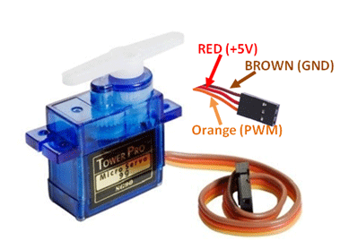
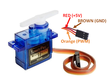 reef ravine
@north stream does the UNO regulator provide enough current for that puppy?
north stream
Looks like it's powered via USB (not a servo motor). Should be enough current available to run a small unloaded servo like that.
reef ravine
ok then connect red on servo to +5, brown on servo to ground, orange on servo to PWM on pin 3
reef ravine
run standard example, make sure servo pin is 3
Open-source electronic prototyping platform enabling users to create interactive electronic objects.
reef ravine
the example uses pin 9, either move the signal wire or change example to pin 3
distant plinth
ok thanks i will try the code now
it didnt work 😦 😦
😦
when i put on the horn on the servo motor and try to move it manually it makes a single noise and move a little bit
it used to move quite smoothly
reef ravine
brb, dinner
reef ravine
make sure you changed myservo.attach(9); in example code to myservo.attach(3); in the code you are running
distant plinth
i moved the signal wire from 3 to 9 instead
reef ravine
does the servo move, jitter, or make any noise at all if you unplug the UNO then plug it back in?
distant plinth
no sadly
 sturdy plover
I am getting this error when I try to upload code to my adafruit bluefruit sense. Can somone help? Arduino: 1.8.12 (Windows 10), Board: "Adafruit Feather Bluefruit Sense, 0.3.2 SoftDevice s140 6.1.1, Level 2 (Full Debug)"
exec: "C:\Users\Aidan\AppData\Local\Arduino15\packages\adafruit\hardware\nrf52\0.20.1/tools/adafruit-nrfutil/win32/adafruit-nrfutil.exe": file does not exist
Error compiling for board Adafruit Feather Bluefruit Sense.
This report would have more information with
"Show verbose output during compilation"
option enabled in File -> Preferences.
reef ravine
@distant plinth all i can suggest is triple checking your wiring, if all you have is +5v i doubt you killed the servo, did the example upload with no errors?
distant plinth
my wiring is good i think
i think the servo is dead
maybe
i dont want to buy another one until i guarantee that this one is dead
my display isnt working also
it doesnt show text omg
reef ravine
does the basic blink sketch work?
distant plinth
for the lcd ?
distant plinth
yup
i have some leds, resistor and a buzzer and they work perfectly with my ardublock code
reef ravine
File | Examples | Basic | Blink
distant plinth
yes it works
reef ravine
ok, the UNO is good then
reef ravine
do you have both the servo and LCD connected ?
distant plinth
i have them but not conneted why ?
reef ravine
they might interfere with each other , ok
reef ravine
if you unplug UNO from USB, turn servo to one end by hand, then plug USB back in what happens?
distant plinth
i do this while the servo code is uploaded and the servo is conneted ?
reef ravine
yes, just unplug UNO from USB
while unplugged you should be able to turn servo by hand
leave it at one end of travel
then plug USB back in
distant plinth
when i move it manually by hand, i put it to 180 degrees
reef ravine
put the servo full left or full right
distant plinth
i did this when the usb is unplugged and when plugged in nothing happende
happened
the code is uploaded btw
reef ravine
ok, then you really need a multimeter to go further
distant plinth
when i move it manually by hand sometimes it moves smoothly and sometimes it moves slowly with a harsh clicking sound
i dont have one sadly
reef ravine
harsh click is not good... it should just whine a little (gear noise)
reef ravine
good luck cya!
simple horizon
Does anyone know why the adafruit gps library gives me a number in the thousands for lat and long?
reef ravine
probably the standard NEMA format
4916.46,N Latitude 49 deg. 16.45 min. North
12311.12,W Longitude 123 deg. 11.12 min. West
simple horizon
Anyway to convert to a number in the tens?
I assume just convert to int and divide by 100
reef ravine
@simple horizon 4916.46,N = Latitude 49 deg. 16.45 min. North, you can divide by 100 to get degrees, the 16.45 minutes needs to be converted to "Google" format 49.xyz
simple horizon
Also, how can I increase the accuracy? It's about 16.6Km off
reef ravine
clear sky?
reef ravine
plenty of sats?
simple horizon
11
simple horizon
Mine is on battery power at 1200mah
I need to test for wearable conditions so it needs battery power
reef ravine
it's 16 minutes 45 seconds
reef ravine
a little more math in code and you'll be much closer!
NEMA has been around forever, but GPS units use it
simple horizon
how can I covert it?
reef ravine
16 minutes is a fraction of 60, then 45 seconds is a fraction of a minute. degrees + mins + secs is the familiar 49.1234 format
north stream
Decimal degrees = degrees + ((seconds / 60) + minutes) / 60
simple horizon
Now we are at 577m
reef ravine
577m error?
reef ravine
sounds like the math code is still a little off, 15m in alt is normal
simple horizon
I havent done the math yet. Just plugging into the format
reef ravine
https://www.rapidtables.com/convert/number/degrees-minutes-seconds-to-degrees.html, what does that give?
Online reference and tools - calculators, converters, math, electricity, web design
simple horizon
4916.46,N -> 49°16'46.0"N
reef ravine
= 49.27944°
reef ravine
its not point46, its 46 minutes
if you plug your reading into the calc above, how far off are you?
16 minutes is about 1/4 hour or about .27 of an hour
reef ravine
do you know what nema message you are sending, or a link to the code?
standard arduino example?
simple horizon
standard example with just display stuff added
reef ravine
oled?
reef ravine
so closing in on correct?
simple horizon
yes
reef ravine
does need to "warm up" for a few
simple horizon
Idk, I don't have that displayed. It has the correct date which isnt that hard to mess up
reef ravine
roof overhead?
simple horizon
actually the error is close to like 17.5m
So, that's pretty acceptable for it being at a window
reef ravine
i think they are rated at 10 - 15 m
but usually closer in US at least
17m much better than 17Km 🙂
simple horizon
I agree
hybrid fossil
Anyone used: ATMEAG328 with integrated 24L01?
Saw one in aliexpress and it seems what i need, i want nano +radio transmitter/reciever so first though take nano+hc 12 for simplicity, but saw this.
How you send msg when its integrated and not through pin?:/
https://a.aliexpress.com/_dVNyKL0

aliexpress.com
Smarter Shopping, Better Living! Aliexpress.com
simple horizon
wow the altitude is actually only 1.70m off
I am on a second story as well so more like it's pretty spot on
safe halo
How do I find out what is causing my crash on an ESP32??
I have a constant for loop running that reads a sensor on that core.
===============================
Guru Meditation Error: Core  1 panic'ed (LoadProhibited). Exception was unhandled.
Core 1 register dump:
PC      : 0x400014fd  PS      : 0x00060230  A0      : 0x800df8aa  A1      : 0x3ffb1a70
A2      : 0x00000000  A3      : 0xfffffffc  A4      : 0x000000ff  A5      : 0x0000ff00
A6      : 0x00ff0000  A7      : 0xff000000  A8      : 0x00000000  A9      : 0x3ffb1a50
A10     : 0x3ffb1b00  A11     : 0x00000000  A12     : 0x3ffc20a0  A13     : 0x5f936abb
A14     : 0x00000000  A15     : 0x3ffb0060  SAR     : 0x0000000a  EXCCAUSE: 0x0000001c
EXCVADDR: 0x00000000  LBEG    : 0x400014fd  LEND    : 0x4000150d  LCOUNT  : 0xffffffff

Backtrace: 0x400014fd:0x3ffb1a70 0x400df8a7:0x3ffb1a80 0x400df935:0x3ffb1ab0 0x400d48b1:0x3ffb1ad0 0x400d519a:0x3ffb1b30 0x4017ee5a:0x3ffb1bf0 0x4017fdca:0x3ffb1c10
0x400df3a3:0x3ffb1c40 0x400e0931:0x3ffb1c60 0x4017fe31:0x3ffb1c90 0x400e0b9a:0x3ffb1cb0 0x400e0c26:0x3ffb1ce0 0x400e0e39:0x3ffb1d00 0x400e0ebe:0x3ffb1d40 0x400e0b9a:0x3ffb1d60 0x400e0c26:0x3ffb1d90 0x400e0c8d:0x3ffb1db0 0x400e0dd6:0x3ffb1df0 0x400e0ebe:0x3ffb1e30 0x400e0b9a:0x3ffb1e50 0x400e0c26:0x3ffb1e80 0x400e0c8d:0x3ffb1ea0
0x400e0e7a:0x3ffb1ee0 0x400e0ea3:0x3ffb1f20 0x400e03b9:0x3ffb1f40 0x400e0435:0x3ffb1f70 0x400d3062:0x3ffb1f90 0x400e4861:0x3ffb1fb0 0x400893bd:0x3ffb1fd0
Normally people use the Arduino IDE which uses wiring, I dialect of C
And @safe halo there is a tool but i dont remember what its called
@safe halo https://github.com/me-no-dev/EspExceptionDecoder I think this is it

GitHub
Exception Stack Trace Decoder for ESP8266 and ESP32 - me-no-dev/EspExceptionDecoder
north stream
@safe halo Looks like the proximate cause was LoadProhibited which sounds to me like fetching from a bad address, like a buffer overflow or uninitialized pointer. If you can get a symbol dump of your program, you can see what it was doing at 0x400014fd. I'm guessing that EXCVADDR: 0x00000000 means "exception virtual address 0", or in other words, it was trying to dereference a null pointer.
elder hare
anyone here who have a ESP32 and some WS2812B neopixels who can help me test and debug my code... it works on my ESP8266 but the ESP32 just wont....
 sweet bloom
hey y'all please pardon my noob, very uneducated questions - i know very little about hardware and am trying to jump into a project and understand what needs to be done
i'm trying to understand powering an arduino project...there appears to be situations where you need to be aware that you're underpowering it with 5v vs DC 7-12v etc etc
and then when i'm trying to wrap my head around that i'm reading about the motor i want to use and saw this:
It can run straight off the arduino, however, if there is a load on the motor, a 5V external power supply is required.
what is the deal with an external power supply? i would imagine my project needing one plug that i plug in...
north stream
You generally need a second power supply if it's not just a small motor.
The Arduino runs on 5V, which it can get two ways: if you have a 5V supply available, there are ways to hook that up directly (when hooked to USB, this is how the Arduino is powered). The other way is to use the Arduino's DC input and let its onboard regulator use that as a source to produce 5V.
What some people do is use a battery pack to run both the motor and the Arduino via its DC input jack. The thing to avoid is trying to run the motor off the 5V logic supply, as the motor can produce electrical interference which can cause the logic to misbehave.
sweet bloom
😳
That sounds odd to me, the need to have a battery in something that's powered by a plug

Adafruit Learning System
Stackable, high current DC and Stepper motor shield
north stream
You don't technically need a battery, but you do need some source of power.
sweet bloom
looks like this describes the options
i just would have imagined one plug powering the entire shebang is all 🤷♂️
north stream
That's entirely possible, and what I described above: using a higher voltage (7-12 volt) supply to run both the motor(s) and the Arduino via its voltage regulator: that way the voltage regulator provides the isolation between the power supply and the logic.
It's tempting to run everything off the same 5 volt supply, but that's the approach that's likely to cause problems, which is why I recommend using a higher voltage supply and the regulator instead.
sweet bloom
Ah okay cool, I'm going to plan to use this then:
Model: TSL-0901
Input: 100V~240V , 50~60Hz
Output: DC 9V 1A / 1000mA
second question, i believe i read i need to be concerned about hooking the arduino up with usb so i can use sketch while also being hooked up to dc, is that correct?
also might anyone have a good resource for learning about this?
north stream
The Arduino will auto-switch between supplies, so it's safe to leave it hooked up to the 9V supply while connecting it to USB.
There's some useful information here https://learn.adafruit.com/lesson-0-getting-started
sweet bloom
cool, thanks a lot for your help 🙏
tidal peak
Ok, so I'm trying to integrate a gyro. I originally had a different code that seemed to drift a lot. So I found an example code and altered it and it seems not to drift. I remade mine to be more like the example code, but it still drifts a lot and I can't find any major difference that would cause it. Anyone any ideas?
-My Code
https://gist.github.com/aguirre537/7b4d3fc697e089546fb3abb4faca9581

-Altered Example Code
https://gist.github.com/aguirre537/aab666674d658b3f8225f23fc0921db9
north stream
Initial calibration values are pretty different and they're later used for drift correction
tidal peak
they are? how? I've printed them in both codes to compare and they're near identical @north stream