#help-with-arduino
1 messages · Page 58 of 1
 stuck coral
stuck coral
stuck coral
Well where on earth did you get the double.parse() function from?
 runic lava
this probably wasnt smart, but i followed a c++ tutorial
and the library is from a previous attempt
I am trying to convert the string to a double.
stuck coral
Might have better luck with atof
Which is a highlighted keyword in Arduino so should work just fine
runic lava
still the same
stuck coral
What do you mean?
Try removing the double keyword from volt in setup
You already decalred volt globally
stuck coral
Also, I can see what you're trying to do, why are you going from a souble to a string in setup and not loop?
You dont get input until loop
runic lava
ohhh
stuck coral
You should also be able to remove stdlib.h
What are you doing with input after you convert it to a float?
Or, would if the loop were setup right
runic lava
I want to read the input, then convert it into a float so that I can use it in my equation
stuck coral
Between when you get the variable and print the variable, so yes
stuck coral
Because you have String in front of input when you call atof
You also might need a char array not string object for atof
runic lava
ok
is there a way to do string or something else?
i need to use decimals
are you aware of anything else that I can use that will still allow me to use string
stuck coral
Well I think you misunderstand a bit
String objects are a helper class for Arduino, it makes handling strings easy. You should convert it to a char array, try to use char arrays instead of string object. Both can store a "string"
You can use input.toCharArray() to convert it easily
Im playing a game so @ me if you need me
stuck coral
Need to pass a char array into the function
runic lava
@stuck coral
I decided to just fo with ints and char
then i will divide
but it won't work
the atoi isnt working
stuck coral
Well because you would be giving it a number and a newline. Atoi works just fine.
You should look at some of the serial input arduino examples
runic lava
ok
i think that there is something wrong with me
i typed the number 4
@stuck coral
the sample code is straight off of arduino.cc
stuck coral
Haha, it's okay @runic lava you are learning c there is a bit of a learning curve
stuck coral
What did you type in?
runic lava
4
runic lava
Ohh
stuck coral
If I remember right the Arduino page with this code explains it a bit
stuck coral
Well there's also a newline or return character when you press enter
 reef ravine
@runic lava a suggestion, change DEC in line 15 to HEX, you'll see the actual bytes being sent
runic lava
thanks
 safe halo
Hiya I am really struggling to find a good example of ESP32 OTA via HTTP. I have tried using and modifying the one that come as an example from espressif but cannot get it to work inside my project. Anyone have any examples that are working?
stuck coral
I think the S3 example is good and I have used it in the past, would be easy to modify for not S3 https://github.com/espressif/arduino-esp32/blob/master/libraries/Update/examples/AWS_S3_OTA_Update/AWS_S3_OTA_Update.ino

GitHub
Arduino core for the ESP32. Contribute to espressif/arduino-esp32 development by creating an account on GitHub.
 knotty bobcat
char notesToPlay[9][2] = {};
char melodyData[9][2] = {
    {NOTE_C4, 5.2},
    {NOTE_G3, 10.4},
    {NOTE_G3, 10.4},
    {NOTE_A3, 5.2},
    {NOTE_G3, 5.2},
    {0, 5.2},
    {NOTE_B3, 5.2},
    {NOTE_C4, 5.2},
    {0, 0}
};
How would I remove an element at the first index from an array?
I've tried googling it, but I wasn't able to find any answers that worked, and it seems this isn't even implemented(?) Would it be easier to keep track of if each of the notes has been played in notesToPlay? It seems fairly ineffective to iterate through a growing array every loop though
The array notesToPlay is copied from melodyData when an event fires, and I'm reading through notesToPlay every loop to see if there's anything I need to update.
Basically I'm trying to make a version of https://www.arduino.cc/en/Tutorial/toneMelody that won't block the adafruit event loop, is there an easier way to complete this higher goal?
Open-source electronic prototyping platform enabling users to create interactive electronic objects.
 fierce heron
hi, how can i use 3 while loops at the same time, i am making a traffic light system and each loop is for a different sequence. i have 3 buttons and the program should detect when a new one is pressed and change sequence
 flint smelt
Weird, I can't access the COM port that the PyGamer is on (in Windows)
Keeps giving me Access Denied. I did forget to switch to TinyUSB (recompiling now). But surely that isn't it, right?
 dense valve
There was a question in the forums about capacitive input on the CLUE in Arduino programming. I don't know the answer but I put a few notes on what's out there in there. Is there an Adafruit_CLUE arduino library? I've not found one yet... https://forums.adafruit.com/viewtopic.php?f=65&t=164043
 north stream
Doesn't look like it? https://github.com/adafruit?q=clue&type=&language=
 pine bramble
@fierce heron Change every while to an if and put it in the loop function, that will loop around it and select the correct sequence every time
fierce heron
@pine bramble ok, thank you 😃😃
dense valve
@north stream Indeed, thanks for confirming my suspicions. I put a comment in on the commits for the CPB code to raise it as an issue. I'm sure it's all in the pipeline
 elder hare
i have a ring of 24 LED's and a 5V 5A adapter and an UNO, can i run this ring on full brightness (WHITE COLOR) on the uno or should i run the power separately?
 cedar mountain
You should generally run the power separately for high-current devices.
elder hare
hmmmm
running both potmeter and a WS2812B ring creates weird values on the pot :S
without the led ring the potmeter reads 0 to 1023 but when i connect the ring led it's 50 to 920
flint smelt
Where's the best place to get assets for PyGamer?
 mellow yew
I'm following the instructions here: https://learn.adafruit.com/adafruit-pybadge/using-with-arduino-ide However, I cannot find Adafruit SAMD even with "all" selected. Any advice?

Adafruit Learning System
What's the size of a credit card and can run CircuitPython, MakeCode Arcade or Arduino? That's right, its the Adafruit PyBadge!
stuck coral
Did you copy https://adafruit.github.io/arduino-board-index/package_adafruit_index.json into your preferences for the board file?
mellow yew
That explains the problem. The page I was following didn't have the link included.
stuck coral
It is in the guide if you check the page before the one you linked @mellow yew
Adafruit Learning System
What's the size of a credit card and can run CircuitPython, MakeCode Arcade or Arduino? That's right, its the Adafruit PyBadge!
mellow yew
I totally missed that page. I think I assumed the Adafruit boards were part of the Arduino default list.
Thank you.
stuck coral
You're welcome, have fun
 slow sierra
Hi, I'm using the Adafruit Feather Basic and the sketch i made uses 77% of program storage space, but only a few variables. I'm getting some spurious results and would like to know how big a chance that i may be clobbering my storage at that percentage.
stuck coral
@slow sierra what libraries are you using?
north stream
Usually it's RAM use that causes issues, not flash use.
stuck coral
Program storage space would be FLASH no?
slow sierra
#include <SD.h>
#include <Adafruit_VS1053.h>
#include <Keypad.h>
#include <Adafruit_NeoPixel.h>
north stream
Yes, the program itself is stored in flash, variables are stored in RAM. The SD library eats up a ton of RAM all by itself.
stuck coral
Is that right @north stream? Program storage space vs program memory?
slow sierra
Ok, well, i've taken out every string and Serial.print command and reduced it to 72% and still getting some curious results.
north stream
Yes, there are three kinds of memory, RAM, flash, and EEPROM. Normally RAM is used to hold data structures, variables, and the like, and flash is used to hold program instructions, data that doesn't change, and the like.
The Feather Basic 32U4 has 2kB of RAM and 32kB of flash.
stuck coral
Feather proto doesnt have eeprom, but the program isnt loaded into flash at boot like a comptuer
north stream
The Feather Basic M0 has 32kB of RAM and 256kB of flash.
slow sierra
Ahh, ok. Thanks @north stream - and i was hoping to keep using the Feather basic.
 floral swan
@slow sierra Which feather basic are you using though?
slow sierra
32u4
floral swan
Gotcha
north stream
It's probably possible to fit all that on a 32U4, but not easily, you'd probably have to modify the libraries to take up less space (I did this with the FONA library to fit it on a different CPU once).
reef ravine
you may be running out of RAM depending on how many pixels you are driving
floral swan
Thats got a little less in the way of memory then
slow sierra
Waaah, me love me pretty lights!
north stream
The Feather Basic M0 has a lot more resources, and would probably be your easiest way forward (other than the annoyance of having to order another board).
stuck coral
I agree, there is little reason to use a 32u4, the M0 will even consume less power in sleep and such
floral swan
Agreed
slow sierra
I may have ordered one a while back. Now i have to rummage thru my little baggies.
north stream
Using 77% of flash shouldn't be a problem.
stuck coral
Othereise the compiler would say dynamic memory not program storage space
I mean, you are probably also having a memory issue
slow sierra
What are the persistant storage areas. The things i #define or the constants set up in void Setup?
north stream
The compiler doesn't really check RAM usage directly, that's more complicated and subtle than just counting up how much flash is used.
stuck coral
^
north stream
You can move constants out of RAM and into flash by using the right storage types and keywords.
north stream
However, the SD library still eats up a ton of RAM, the VS library uses a chunk too, and the NeoPixel library uses an amount proportional to the number of LEDs it's controlling.
stuck coral
But the 32u4 I dont think you can just copy contents into PROGMEM but I could be mistaken.
 stuck coral
and still getting some curious results.
@slow sierra this is probably running out of RAM
north stream
Check out the "solving memory problems" section of the page I linked to above...
stuck coral
What are the persistant storage areas. The things i #define or the constants set up in void Setup?
@slow sierra it would be constant variables, or the code you wrote as an executable in memory
north stream
In particular, this page on optimizing RAM usage https://learn.adafruit.com/memories-of-an-arduino/optimizing-sram
slow sierra
Thanks ALL! I now have areas to check and rethink or maybe work with a larger RAM with the M0.
stuck coral
You'll love the M0, taste a SERCOM and you'll never go back
north stream
The M0 is a lot faster too. It's a great CPU.
slow sierra
SERCOM kinda seems scary... i don't know why. Maybe it's just adding another layer, but i'm being a baby, i know.
north stream
Luckily, the libraries work well on both CPUs, taking care of a lot of the details for you.
stuck coral
Oh being able to make a connector for a module with I2C, SPI, or Serial is so powerful. And it means if you want multiple SPI buses its pretty straight forward without bit banging
slow sierra
Yeah, i've faced multiple serial 'problems' before and it got kinda messy even with Software Serial.
north stream
Note: you'll probably want a level shifter to talk to the NeoPixels. They'll generally mostly work with 3.3V but it's not guaranteed.
slow sierra
I'm using 3.3 with the NEOs now, except for power to them.
Kinda wish they made a 5V feather...
I'm sorta old school 5V guy.
north stream
The ItsyBitsy has a built-in level shifter for driving NeoPixels.
reef ravine
ahhh TTL....
slow sierra
@reef ravine Yeah, that's what i'm talkin' bout!
north stream
I'm having the same problem, I want to use an FPGA for a project, and there just aren't any 5V FPGAs. I'm thinking of making a little breakout board to hold the FPGA along with its power supply and clock circuitry, and a bunch of level shifters, that would be DIP format and plug into an IC socket or breadboard.
slow sierra
I gotta say this was my first question posed to the Adafruit Discord - previously used their forums - and it was nice to actually talk to people.
reef ravine
@slow sierra I recently moved from a 328P to a SAMD51, it's night and day from 2K to 256K and get used to 3.3v, 1.8 is coming 🙂
north stream
I'm old school too: when I'm not building stuff with vacuum tubes or nixie tubes, I'm doing nutty things like breadboarding an 1802 CPU chip.
slow sierra
@reef ravine oh jeez... ok.
reef ravine
arduino AND Nixies, its quite a conversation starter
north stream
Yeah, those "3.3V" FPGAs often have a 1.8V or 1.2V core, and built-in level shifters to 3.3V for the I/O pins.
slow sierra
@north stream Whoah.
north stream
Arduino + nixies + foil tape
reef ravine
I think my Cosmac Elf used an 1802....
slow sierra
For my other project with the VS_1053 i knew it'd be large and challenging and went with the Teensy 3.2
north stream
Yup, the Elf was 1802 based. It's an interesting CPU.
reef ravine
so long ago, set the byte on switches, load, repeat...
north stream
The Teensy 3.2 is a real powerhouse.
slow sierra
And i recently bought a Teensy 4.0 that i can't wait to use for music synth!
north stream
The control board for the nixie project basically has an Arduino condensed onto the left end of the board.
slow sierra
@north stream Nice compaction!
stuck coral
Oshpark customer I see
reef ravine
and no Russian drivers for you eh?
north stream
I have some of the Russian chips, but still had some of the ceramic packaged 74141s and couldn't resist using them.
slow sierra
Well thanks for the info y'all. I'm off to search for my M0 Feather. Take care and be safe!
reef ravine
i assume you've seen https://www.daliborfarny.com/, can't wait to hit the lottery....
happy hacking @slow sierra
north stream
I had Dalibor make me one of his tubes with a mesh anode all the way around instead of solid at the back.
north stream
When he was just getting started, he was looking for suppliers for various unusual raw materials, so I pointed him to almetals.com
stuck coral
Boy, pointers to pointers really throw me for a loop, I spent a long time starting at my terminal for a single extra *
reef ravine
i'm not familiar with tube production, i thought some steel and a spot welder...
@stuck coral I am so happy to be able to comprehend your pain, but pointers alone are pushing it for me 🙂
stuck coral
I'm glad others can relate 😜
slow sierra
Hey @stuck coral @north stream Thanks for the help - i reduced Neopixels and did some storage types and keyword cleanup and it works! Though, i feel i'm on the precipice and not going to add any more bells and whistles to the project. It works fine now.
north stream
Good going! You can always double up NeoPixels if you don't mind having sets of them doing the same thing.
slow sierra
Ahh, interesting. In this thing it might be ok like that.
The project is based on someone gifting me one of those old Radio Shack clear push-button phones and now i've made it so i can punch in any number and it plays a file off the SD card. Of course, if it's not available, it says "I'm sorry, that's not a working number."
stuck coral
Havnt seen a headset like that in a while
slow sierra
It originally had a neon tube in it which i couldn't get working.
stuck coral
I think you might find others here are really good with stuff like that
reef ravine
more D batteries!
slow sierra
Yeah, well i guess i kinda wanted to rework it with LEDs because i love Neopixel strips.
It's working now so i'm a happy pappy. Thanks for the cool convo too.
north stream
Oh slick! I love neon tubes, but they do make some electrical noise.
I made a similar project out of a kid's toy to play tunes like that a while back. https://blog.adafruit.com/2011/03/02/frankenpod/

Adafruit Industries - Makers, hackers, artists, designers and engineers!
John writes in … A friend wanted me to modify a toy music player to play her choice of music. I ended up using a Waveshield as an SD card reader, player, and amplifier, a Mintyboost to power …
 wintry berry
Any idea how to detect tapping on foot pedal? the pedal is potentiometer that connect an analog input?
flint smelt
You can absolutely connect a pot to an analog input. I'm not sure if that answers your question, if not you might try rephrasing it?
pine bramble
Reference 3.3 volts at top of pot. GND at bottom; center tap is to the ADC input of the MCU.
You can also move the range of the center tap by adding series resistance to top or bottom leg, externally.
(or use a second pot to change that series resistance)
 austere bloom
This is a wiring diagram for a stepper motor, but I'm confused as to why there is a (black) wire going from the Arduino's ground port to the -ve terminal on the breadboard. What does it do and does it need to be there? What would happen if I removed it?
 proven mauve
So... I've got 2 chips on a board that share a ground and one talks to the other by sending midi messages from a serial midi out to a serial midi in.These midi out's are also sent to a midi jack, the connection to the jack out is a shared single connection to the second chip. Midi is High when idle, and goes low to send data bits. There are specific messages that I don't want to send to the second chip, but everything should always be sent to the jack. And I'm really short on program space and still have room on my circuit board so Im looking for more of a hardware-centric solution, as I don't want to create a whole second software midi serial device in the program (extra libraries and all sorts of nonsense). I'm wondering if adding a diode and then a transistor to the line to the second chip could potentially be a fix. First chip sets a pin high when a message should not go to the second chip, pin high activates transistor placed after the line separates between the midi jack and second chip (5v -> second chip) which keeps the branch to the second chip's line high (idle), diode prevents the 5v from travelling backwards to the midi jack and the message is still able to be sent through the jack.... Does this seem logical?...
 fiery lichen
Is there any obvious reason a 32u4 feather Bluefruit wouldn’t charge a lithium cylinder battery? Left it hooked up all night and the voltage on the battery reads zero
When battery is unplugged and usb is plugged into board, bat pin reads 4.3v
Does that mean the battery somehow blew up?
There’s also nothing wrong with hooking neopixel+ directly to the positive battery wire and neopixel- to the negative battery wire to avoid driving large currents through the board traces?
 proven frigate
Hello dear community, I have a question regarding the Powerboost 500C. My plan is to have an ESP32CAM board sitting outside, and it is powered using a 6V 1,1W (according to specs) solar panel. Now I wonder if it is a problem to have the Powerboost charging an Samsung INR18650 using that solar panel. I researcher already a bit, but couldn't find any helpful articles, so I tried it out. I also added a diode. It seems to work fine, it does charge. Now I wonder: Is it bad for the battery/powerboost to be charged with (sometimes) lower voltages, when there is some shadow? Thank you so much! 🙂
proven mauve
@fiery lichen was the battery at 0v when you started?
if I rember right, lithiums that drop that low need to be rescued and/or are dead dead
fiery lichen
No it wasn’t that low
It was running fine, handed it off to someone else and when I got it back when it was “broken” I saw the voltage read zero.
Does the cylinder batteries have a circuit to protect it from going that low?
Adafruit site says it does.....weird
 versed quiver
Hello, I am trying to use a ht16k33 LED matrix driver board with a pro trinket to control 64 LEDs for an organ registry.
Problem is just the programming. I want to have all the LEDs in a single int array because that will be really easy to work with.
Problem is just that the Adafruit_LED_Backpack library lets you address the LEDs with x and y coordinates (two arrays of 8), not in a single array of 64.
I have also looked at the Adafruit GFX library, but it doesn't seem very helpful.
So, does anyone have an idea about how I can do this?
Basically, what I want is to put all possible combinations of these two, which will always = 0 or 1
int x[8]
int y[8]
``` into this one array `int note[64]`This is sort of my first project and any help/insight is much appreciated.
north stream
@austere bloom That's a "zero volt" or "ground" reference, so the two boards can communicate. The Arduino controls the stepper board with varying voltage signals, and voltages can only exist between two points. The black wire provides the second (or "reference") point for the control signals.
austere bloom
it can use the ground pin to do that?
north stream
@versed quiver Internally, the array is 1-dimensional and the library translates back and forth. I don't remember if the library gives access to its internal memory, but if so, you could just take that pointer, cast it to a 1-dimensional array pointer, and use that directly. Otherwise, you might have to slightly modify the library (it's not too hard, I've done it for other projects).
austere bloom
or does that complete a circuit between the two
north stream
@austere bloom Yes, the ground pin is the usual choice.
And yes, it does complete the circuit.
austere bloom
I see. thanks!
 gentle kite
thank you everyone
north stream
@gentle kite There are a few possibilities. The likely one is the electronics themselves, but it's also possible for the motor itself or the sensing resistor to be faulty. To check the motor, disconnect one of the motor wires from the electronics (to avoid damaging the electronics), and feed power to it. It should spin.
@fiery lichen Packs like that will read 0V if the protection circuitry has operated to disconnect them. If so, you'll need to "wake up" or reset the protection circuitry.
versed quiver
I have come up with this: ```
int ledtonote()
{
int i, j, k = 0;
for ( i = 0; i < 7; i++)
{
for (j = 0; j < 7; j++)
{
led[i][j] = note[k];
k++;
}
}
return 0;
}
@north stream how does one wake them up? Shout at it? Shake it vigorously? 🙂
 magic field
@versed quiver no.
versed quiver
@magic field Okay, do you have any ideas?
Also, do you want to explain why (or point me in the right direction or something?)
fiery lichen
@north stream if the neopixel signal pin is connected to a micro that is “off” do the neopixels still draw a small current if the + and - of the neopixels are wired directly to the battery?
north stream
Generally you hook the pack to a charger, the protection circuit will generally allow a tiny charging current through until the cell voltage rises a little. Some chargers won't like this, as they won't see a valid pack connected, so you may need to use a dumb charger or just a current limited power supply until the protection circuit operates.
fiery lichen
All I have is the feather, will that not work?
north stream
The NeoPixels will still draw some current. If they're lit, they can draw significant current, but even if they're all off, their control electronics will still use some power.
fiery lichen
Ok! That might be the cause
So I need to wire a switch in line with the + neopixel wire
How can I ensure things are OFF off?
north stream
I think the charging chip on the Feather will try to send pulses if it doesn't see a cell, as it will attempt to apply voltage, see it rise quickly, give up, see it fall, try again. However, doing this for a while might well wake up the pack.
Easiest way to make sure it's off is with a power switch or just unplug it.
fiery lichen
Yeah I think a switch might be in order
north stream
For automatic control, you can use a relay or a MOSFET like the one in the battery protection circuit to disconnect the load.
fiery lichen
Ah yes
north stream
There are some breakouts for this purpose like https://www.adafruit.com/product/1400
fiery lichen
Well it’s good to know that the neopixels still drains if the pixels are off.
The more you know. 🙂
north stream
Another possibility https://www.adafruit.com/product/3435
proven mauve
@north stream does my transistor idea/diagram up above seem feasable?
north stream
Not totally sure on that one. Seems like it might work, but you might need a current source or something instead, I vaguely remember MIDI uses current loop signalling.
magic field
@versed quiver return k; you have no reason to return 0;. then you can check the value of k, and see the error
versed quiver
Okay, that was smart.
But now I wrote this cpp program to test it:
int note[16] = { 1, 2, 3, 4, 5, 6, 7, 8, 9, 10, 11, 12, 13, 14, 15, 16};
int led[4][4] = { { 0, 0, 0, 0}, {0, 0, 0, 0}, { 0, 0, 0, 0}, {0, 0, 0, 0} };

int main()
{
  int i, j, k = 0;
  for ( i = 0; i < 4; i++)
  {
    for (j = 0; j < 4; j++)
    {
      printf("%d   ", led[i][j]);
      led[i][j] = note[k];
      k++;
    }
    printf("\n");
  }
  printf("1D-Array\n");
  for ( i = 0; i < 16; i++)
    printf("%d ", note[i]);
  return k;
}
and it returns
$ ./a.out
0   0   0   0
0   0   0   0
0   0   0   0
0   0   0   0
1D-Array
1 2 3 4 5 6 7 8 9 10 11 12 13 14 15 16 $
Which is not really what I was trying to do.
Oh, I think I see the problem, I print led[i][j] before I write to it.
Yes, that was the problem.
So, now it works.
Thank you for the help, now I just have to figure out how to use a two dimensional int array as two 1 dimensional int arrays.
fiery lichen
@north stream any idea where i could get one of these?
https://www.adafruit.com/product/1685
Can handle up to 3A.
But since only one circuit is active per push, one way I can have it complete a circuit to put En to ground and open the neopixel circuit, the other way the En pin is floating And the neopixel circuit is completed. Seems like it would be a perfect solution

Push once to turn one side on, push again to turn the other side on! It's basically a push-button toggle switch that connects and disconnects the middle pin from either of the two side ...
Is that just a SPDT?
north stream
Yeah, I think so. Might be able to use a rough equivalent like https://www.digikey.com/product-detail/en/judco-manufacturing-inc/40-3145-01/511PB-ND/254286
fiery lichen
That’s SPST. Is there a SPDT? That way I only need one button
Order today, ships today. 40-3657-00 – Pushbutton Switch SPDT Standard Panel Mount, Rear from Judco Manufacturing Inc.. Pricing and Availability on millions of electronic components from Digi-Key Electronics.
Maybe this?
It says “on-off-on”
Not sure I understand what that means. Does that mean the pins alternate being on like the original switch? @north stream
versed quiver
Should I care about these warnings? ```
/home/mats/Arduino/test_ht16k33/test_ht16k33.ino: In function 'NoteToLed()':
/home/mats/Arduino/test_ht16k33/test_ht16k33.ino:25:17: warning: iteration 7 invokes undefined behavior [-Waggressive-loop-optimizations]
led[i][j] = note[k];
~~^
/home/mats/Arduino/test_ht16k33/test_ht16k33.ino:23:19: note: within this loop
for (j = 0; j < 8; j++)
^
Oh, never mind, I just figured it out, it was my bad.
 wind drift
Question:
the internal_ReadWrite for nrf52840.
How can I have it print the data in the file to my serial monitor?
{
  Serial.begin(115200);
  while ( !Serial ) delay(10);   // for nrf52840 with native usb

  Serial.println("Internal Read Write File Example");
  Serial.println();

  // Wait for user input to run. Otherwise the code will
  // always run immediately after flash and create the FILENAME in advance
  Serial.print("Enter to any keys to continue:");
  while ( !Serial.available() )
  {
    delay(1);
  }
  Serial.println();
  Serial.println();

  // Initialize Internal File System
  InternalFS.begin();

  file.open(FILENAME, FILE_O_READ);

  // file existed
  if ( file )
  {
    Serial.println(FILENAME " file exists");

    uint32_t readlen;
    char buffer[64] = { 0 };
    readlen = file.read(buffer, sizeof(buffer));

    buffer[readlen] = 0;
    Serial.println(buffer);
    file.close();
  }else
  {
    Serial.print("Open " FILENAME " file to write ... ");

    if( file.open(FILENAME, FILE_O_WRITE) )
    {
      Serial.println("OK");
      file.write(CONTENTS, strlen(CONTENTS));
      file.close();
    }else
    {
      Serial.println("Failed!");
    }
  }

  Serial.println("Done");
}

// the loop function runs over and over again forever
void loop()
{
}```I mean - I want to write multiple lines of data every few seconds and then read it all after some time
Now I just see this
it seems a bit more complicated than the SD card examples
north stream
@fiery lichen I figured you just needed on/off, not switching between two loads.
versed quiver
I figured it all out and it works now! 😃
north stream
Looks like a beefier ATmega CPU with some 16-bit support and lots of pins. https://www.microchip.com/wwwproducts/en/ATXMEGA64A1U
ATxmega64A1U
Not that I know of, but it probably wouldn't be difficult to add, as it's still an AVR architecture.
A quick web search reveals there is some support out there http://mrp3.com/xmega64d4.html
I wouldn't expect a CPU like that in such an apparently simple device.
Good source of CPUs then
stuck coral
You would be surprised @north stream, vapes actually do a surprising amount more then just flip a MOSFET. Not a ton more, but micro required
north stream
True. The board has a nice 10-pin TagConnect pattern, along with a 6-pin header pattern, so at least one of those probably supports ISP.
stuck coral
I know, I was gonna comment about the tag connector, I love those
Would use Atmel studio or the ASF package for that CPU to program
north stream
A micro isn't strictly required, but I'd expect them to use cheap Padauk or PIC chips, not high pin count AVRs.
stuck coral
True, does seem a little beefy for the application
north stream
Not that I'm complaining, cheap CPU boards with rechargeable cells are always welcome.
stuck coral
Are those protected or unprotected 18650s?
north stream
Not bad at all for $2.
stuck coral
You need something to act as a ICSP programmer like a Arduino/Real programmer, and a dev environment such as ASF or atmel studio
On the picture of the PCB you can see the programming connector with ten pads and three holes, thats whats called a TAG connector
The TAG devices are like $60, i would try to just solder wires
north stream
There may well be a bootloader already on it, it could be those 6 pads are the usual FTDI layout serial port, which makes things easy. Note, you can even use the Arduino IDE to drive an ICSP programmer to flash a bootloader.
stuck coral
Oh that would be amazing
That connector is totally a serial port isnt it @north stream ? 😜
north stream
Can't tell for sure, but that's my first guess (second guess is it's a second ISP connector)
stuck coral
Even if there is no bootloader I wonder what it would be sending out if it is
 sturdy bobcat
Yah, guy on the train used to do electrical engineering work on vapes. They put a lot of work into them, I guess.
north stream
I'd use a clip-on pogo pin adapter to have a quick look to see if it's sending anything.
stuck coral
Well, if you don't @sturdy bobcat they have a tendancey to blow up
Yeah, I think that should do the trick, been a hot minute since Ive used ISP
north stream
Seems like it would, if you adapt it to the pattern on the board somehow.
This is the sort of pogo pin clip I use for quickly attaching to unpopulated serial ports like that one might be.
stuck coral
how would i find that out
Well a good first step is to find ground and presumably +3.3V using your multimeter if you have one handy
sturdy bobcat
You know, the ATXMega series doesn't use the same programming protocol as the ATMega series
north stream
If you're going to start tearing into stuff to get cheap CPUs, it's probably worth it to pick up a $4 multimeter.
stuck coral
Oh I see, PDI and JTAG
Holy crap, this micro is actually wayyyyyyy overkill XD this vape has a AES engine, four DMA channels, 1Mbps ADC, etc etc etc
sturdy bobcat
Holy smokes indeed.
north stream
I see what you did there! 🤪 💨
They've designed (at least) two completely different boards for the same embedded application? Their engineers are probably having a good time.
north stream
That does not look like a cost optimized board to me.
stuck coral
Well I'm willing to bet the STM is a lot cheaper then that first micro but I would agree with that
sturdy bobcat
I know that Juul and their pot sibling company had crazy headcount for a while.
north stream
I suspect the vape manufacturers are copying the inkjet printer model and using the units as loss leaders to sell vape juice.
stuck coral
I see, think thats then a vaporizor device not the slang term "vape", very confusing.
Any RGB?
5G? IoT connectivity?
Blockchain?
Lol, I'm sure
Eh, you'll learn a whole lot
And @north stream you are 100% correct, it is the razorblade model
north stream
I have a pathological inability to ignore cheap cool stuff I can hack.
stuck coral
Are you in Japan?
OK, the only place where you will see a sony label ANYWHERE near a vape stand 😆 Cool beans, hi from across the pond
north stream
Ah, when I see $ I think US/CA/AU, when I see £ I think UK, when I see €, I think EU, and when I see ¥, I think Japan.
stuck coral
Oh I didnt notice the ¥, I saw the sony logo and the print on the packaging
north stream
Originally when TakoSalad said they were $2, I wasn't guessing Japan. But the picture belied that guess.
I suppose you could use the heating tube for incense, a smoke generator for cosplay, or a miniature solder pot.
It's cool that there are people on this Discord from all over the world.
sturdy bobcat
I saw a really really really amazing bubble artist in vegas who was using a tobacco vaper to fill his bubbles with smoke.
As in Neuromancer, the street finds new uses for things.
stuck coral
Lmao, my entire state is into that.
There is nothin to do here, one of the five states without a urban city
Wouldnt it melt its own solder? Doesnt look well insulated
 honest temple
how can i use circuitpython with my arduino?
stuck coral
I wouldnt expect anything less, its pretty cringe

Adafruit Learning System
New to CircuitPython? This is the place to start.
I like how he shows off the parts in the end like he was doing something technical to begin with
honest temple
ik but like how do i use it with my arduino
stuck coral
Well maybe you should ask #circuitpython-dev but you need to use a supported board and double tap reset button to get it on there
north stream
An ordinary Arduino isn't powerful enough to run CircuitPython, unfortunately
north stream
There are some boards that can run CircuitPython (or Micropython) as well as Arduino, but plain garden-variety (ATmega) Arduinos can't run CircuitPython.
stuck coral
This link has a great list of supported boards https://github.com/adafruit/awesome-circuitpython

GitHub
A curated list of awesome CircuitPython guides, videos, libraries, frameworks, software and resources. - adafruit/awesome-circuitpython
honest temple
can arduino run micropython?
stuck coral
Arduino is a C++ framework, you can bring CP into an arduino sketch but only on supported boards with enough RAM and storage
north stream
It can't run Micropython either. However, there are cheap boards (like the Trinket M0) that can.
honest temple
oh wait arduino can run serialpy right?
pyserial
i meant
i dnt want to learn C++
ik python
stuck coral
You'll learn about memory managment 😉
north stream
Maybe pick up something else like a Circuit Playground Express, Metro M4, or Micro:Bit if you want to run Python.
honest temple
i have a micro bit
but for some reason it wont run anything
like when i drag the hex file into it it flashes and does nothing
north stream
Have you tried installing the Mu Python editor? It will set up the Micro:Bit for you.
north stream
I suggest doing it that way, it's a lot easier than trying to do a low level installation manually
honest temple
cos im learning C
north stream
Arduino uses a C++ dialect known as "Wiring", but it's a superset of C, so C code works just fine on it (that's how I usually program Arduinos)
honest temple
oh
ok
all i've done in C so far is this ```c
include <stdio.h>
int main(){
char characterName[] = "John";
printf("His name is %s", characterName);
return 0;
}```
literally all i've done
north stream
In Arduino, that would look like ```c
void setup() {
char characterName[] = "John";
Serial.begin(9600);
Serial.print("His name is ");
Serial.println(characterName);
}
void loop() {
}
why serial.begin?
north stream
That initializes the Arduino's serial port and sets the speed to 9600bps.
honest temple
oh
stuck coral
Learning "arduino" (Wiring) you will improve your C skills, and if you know the C basics you'll feel right at home after the wiring learning curve.
There are also many examples and guides for doing anything you can think of
safe halo
how do I assign a n IP address using a variable? currently I have the following set
uint8_t WiFi_Sta_Address_1 = 0;
uint8_t WiFi_Sta_Address_2 = 0;
uint8_t WiFi_Sta_Address_3 = 0;
uint8_t WiFi_Sta_Address_4 = 0;
I then Load the saved variables in vis JSON
  WiFi_Sta_Address_1 == jsonDoc["WiFi_Sta_Address_1"];
  WiFi_Sta_Address_2 == jsonDoc["WiFi_Sta_Address_2"];
  WiFi_Sta_Address_3 == jsonDoc["WiFi_Sta_Address_3"];
  WiFi_Sta_Address_4 == jsonDoc["WiFi_Sta_Address_4"];
I then assign the variables to the IP address
  IPAddress local_IP(WiFi_Sta_Address_1, // Static IP address
                     WiFi_Sta_Address_2,
                     WiFi_Sta_Address_3,
                     WiFi_Sta_Address_4);
However when I try and connect I get an IP of 0.0.0.0
What am I doing wrong
The JSON readback shows
"WiFi_Sta_Address_1":"192","WiFi_Sta_Address_2":"168","WiFi_Sta_Address_3":"1","WiFi_Sta_Address_4":"35"
 safe shell
@safe halo The second block looks more like boolean expressions (==), rather than assignments (=)
reef ravine
check me anecdata, = means set something to be equal to, == means if something is exactly equal to
so the assignment in block 1 sets all wifi stations to 0, the second block checks if the station addresses are exactly equal to the WiFi_Sta_Address_x and happily returns false
safe shell
That's my interpretation from the snippets too (edited my parenthetical above, which I realized was misleading)
 marsh charm
Anyone know of a solid starter kit for the esp32?
safe shell
@marsh charm What are you wanting to do with it? Plenty of form factors, with varying pin counts , degrees of support circuitry (statics, bootloader mode, voltage regulator, etc). I'm a fan of the Feather Huzzah32 since it plays nicely with the FeatherWings I have, and has LiPoly charging and some other features built in.
safe halo
I am using the heltec_wifi_lora_32_V2
marsh charm
I'm looking to do a wide variety of things. But I want a whole kit I can prototype with then buy things alacarte as I need them
safe halo
How do I assign a JSON document string to a Char[]?
I have
WiFi_SSID = jsonDoc["WiFi_SSID"];
But I cannot assign the value to it. it says invalid type of assignment.
reef ravine
how is WiFi_SSID instantiated? as a uint, other?
safe halo
I have tried both uint8_t[] and char[]
char WiFi_SSID[32];
uint8_t WiFi_SSID[32];
The method takes a uint8_t so not sure how to get that type of value out of a JSON
reef ravine
and inside the JSON "Wifi_SSID" is "192.168.1.100" or similar?
safe halo
The SSID is the wifi name
reef ravine
oh, sorry "My_router" or similar?
safe halo
I can hard code it and it works just fine but I cant load it from a variable
reef ravine
C++ is very picky about types, if you have a String in the JSON it won't load to a char or int
safe halo
I get this error
"message": "incompatible types in assignment of 'ArduinoJson6152_0000010::enable_if<true, ArduinoJson6152_0000010::MemberProxy<ArduinoJson6152_0000010::JsonDocument&, const char*> >::type {aka ArduinoJson6152_0000010::MemberProxy<ArduinoJson6152_0000010::JsonDocument&, const char*>}' to 'char [32]'",
The JSON is sent down integers
reef ravine
in the second block above if you change == to = does it work?
safe halo
I have changed it to const char * as well still no workie
reef ravine
now CP has made me go dumb, I recall char to be the hardest type to wrap my head around in C++
safe halo
so I changed it to "=" and const char * it is now working... and i have less hair.....
reef ravine
because now you are assigning it, not comparing it
sorry about the hair, I looked like Fabio before I started learning to code 🙂
safe shell
@safe halo Did you get the IP address working also?
reef ravine
(of course with the barber shops closed I'm starting to look like him again 😦 )
stuck coral
@reef ravine clippers dont cost anything per session 😉
safe halo
Yes I did thanks
reef ravine
@stuck coral lol, I'll end up with a strange mohawk
safe halo
Im going for the mullet currently....
reef ravine
lol, guess we need to move this to offtopic
so the const char * allowed you to read the SSID?
safe halo
Yes Read it from the JSON file
just found that the esp32 can be both a AP and STA at the same time.. how cool is that...
Combined AP-STA mode (ESP32 is concurrently an access point and a station connected to another access point).
they are amazing products, add wifi for just a few bucks
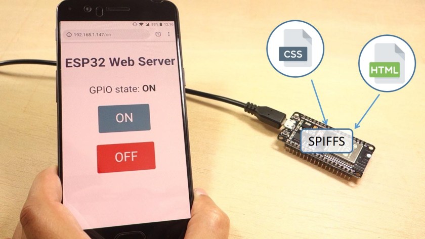
In this In this tutorial we'll show you how to build a web server that serves HTML and CSS files stored on the ESP32 SPIFFS (SPI Flash File System).
safe halo
I have an Async webserver mDNS, Bluetooth and Lora and an OLED display going right now and it cost me £13.. prettya mazin
reef ravine
just looked up your board, a nice piece o kit, how far do you get with LORA?
safe halo
Im just starting it. I have a second device that is already setup as the receiver so hopefully will be done tomorrow.
reef ravine
have you seen the Andreas Spiess YouTube vids on LORA? he's getting 10's of KM's
safe halo
@stuck coral I plan on it these devices are going to be used in the Amazon so I need at least 20k out of them.
stuck coral
Max distance using LoRa was restricted by the curvature of the earth
safe halo
What antenna is that on the right?
stuck coral
Very impressive
Its a antenna I got from RAK
Basically just a PCB tube with a tuned bit of metal in it, isnt too fancy
safe halo
I'm going to have mine be a retransmitter as well so I can just daisy chain them as far as I want.
stuck coral
But its a whole wavelength antenna, I need to do more testing with it but with the one on the left I can get quite the distance. And nice, radiohead is OK for that application
reef ravine
heavy foliage maybe an issue
stuck coral
It is, anything at all in front of it is an issue since its sooooo low power
Thats why I think LoRaWAN is silly
In a lot of cases anyways
safe halo
Thats why I am creating my own using each one as a repeater....
stuck coral
Yes, if you want something that will work quickly check out the radiohead library, the multi-hop isnt good for more thena a few devices when using LoRa but for this case it will do you well.
I made a commercial LoRa security system for low income housing, firewalls were a huge problem, they just ate the signal and we had to create our own LoRa MAC layer for communication with multi-hop.
Physical firewalls, the ones that protect you from fire not the one on your laptop
safe halo
Thanks. Ill have a look at the Radiohead library.. glad they have it on PlatformIO...
stuck coral
Be warned that is not the offical version
Its behind a few commits if I remember correctly
safe halo
It should be good enough to get me started.. or at least find the bug that stops me in my tracks....
stuck coral
Fair enough, in platformIO it is easy to use the extra_lib_dirs in the ini file if you decide you want the newest version
Just to point you in the right direction
 tulip sigil
are we discussing long range wireless technologies? What is your use case for this LoRa project?
safe halo
Monitoring the Water levels along the amazon river and transmitting the data to a collection station for transmission.
tulip sigil
That's a pretty interesting topic 😄 Do you plan on having small devices all the way out in the middle of nowhere then?
stuck coral
You might like a PCB I just got made @safe halo
On the back of an 18650.
These are also going to South America
stuck coral
There is a SERCOM which allows for RS485
Well, two exposed SERCOMs
So you could have two RS485 buses for some reason
safe halo
Would only need one....
 vast cosmos
for the ItsyBitsy nRF52840, should I be using ArduinoBLE or Adafruit's Bluefruit52Lib ?
vast cosmos
im thinking Bluefruit is an older library, that Adafruit had BLE support for some time before Arduino officially supported it, meaning ArduinoBLE is newer. -- so is Bluefruit52 still planned for active development despite Arduino's official support?
 leaden lynx
I am working on a project where I want to control two variables (speed and delay) using the serial monitor. I want to put in "F 30" to change the speed to 30; and I want to put in "D 2000" to delay for 2 seconds. Any thoughts on this?
 mighty vigil
int getSpeed(){
String serialString;
char serialChar;
uint8_t i;
for (i=1;i=Serial.available();i++){
if (Serial.read()=="F"){
break;//The next byte will be actual data
}
}
for (i=1;i=Serial.available();i++){
serialChar=Serial.read();
if(serialChar!=NULL){
serialString=serialString+serialChar;
}
else{
break;
}
}
return serialString.toInt();//convert the string to an integer and return it
}
 robust spoke
Hey, does anybody know how I can send a command from an arduino to my Android phone to run a tasker task?
Or do anything really? I have set mine up to connect to my phone over a serial connection and I can see the arduino in a serial monitor app on my phone, but I don't know how to actually send a command or have my arduino command my phone to do something
proven mauve
What wattage resistors should I be using on the d+ and d- lines of the USB on the atmega32u4? They're 22 ohm resistors and I was thinking the wattage needed to be pretty high, but looking at the pro micro they used some tiny resistors that must be around 1/10watt I would think (little R0201's)....
Your phone needs to be listening to those serial commands and have an app running that will perform an action when it receives specific commands I would think, @robust spoke
robust spoke
Do you know of any app that has that functionality?
I have been looking everywhere and I can't seem to find anything
proven mauve
I'm not sure, maybe IFTTT but that's a stab in the dark
robust spoke
I will check into IFTTT thank you!
I have been using Tasker and looking everywhere around for a plugin that may be able to work but nothing seems to exist
Got to thinking how the functionality that something like a smartwatch has of "Send to phone" works
As far as I can see, IFTTT only supports triggering if a bluetooth device is connected
cedar mountain
@proven mauve Those are termination resistors for the differential data signal, which is less than a volt, so 1/10 watt is plenty.
knotty bobcat
Can anyone spot an obvious flaw in the code below that would cause it to not play the tune I want on a small piezo buzzer? handlePiezo is called every loop, and should emit a simple tune, however the noise coming out of the buzzer lasts much longer than the duration of this tune, and its all the wrong notes too. I'm not quite sure what's going wrong, any pointers?
https://mystb.in/eforuyifod.ino

A fast intuitive paste service.
cedar mountain
The == "\0" check to stop the loop probably isn't working like you expect. That isn't doing a string comparison, but a pointer comparison.
Also, your use of strcpy() in the setup is very dangerous, since that relies on null termination of the string, which you don't really have here.
I don't think it's directly causing your problem, though, since it would happen to work because of the null characters you do have.
(The melody here would last just a fraction of a second if each note is only a few milliseconds, too.)
knotty bobcat
I'm using == "\0" to detect if the array is empty, is there a more efficient way?
The intended melody is a second or two long, though the current output is at least 5-10 seconds long
cedar mountain
It's not a matter of efficiency, but correctness. Right now that comparison is saying, "Is the address of notesToPlay[0] the same as the address of this string constant containing "\0".
knotty bobcat
You're right though, I've realised that the note durations need to be altered, and I also forgot to add delay after each note
ah ok, how would I then detect if the array is empty?
cedar mountain
You'll have to clarify what you mean by "the array is empty", since it's declared as of size [9][2].
Perhaps you are looking for the special 0, 0 value to stop the melody?
Because right now it'll just keep reading off the end.
knotty bobcat
I want to know if the array doesn't contain any smaller arrays inside it, which represent the tone data
cedar mountain
It will always have 9 of them, no matter what, because it's declared to occupy that amount of memory.
knotty bobcat
ah
proven mauve
@cedar mountain thank you. It's been difficult to find voltage data on the USB data lines that I could understand for this
pine bramble
i'am not good at English is ti okay?
I am making a airmouse with arduino micro
but it is not working
this is cord
#include <adxl345.h>
#include <Mouse.h>
#include <I2Cdev.h>
#include <Wire.h>
ADXL345 accel;
//int16_t ax, ay, az;
int ax = A4;
int ay = A5;
int az = A3;
#define LED_PIN 13
bool blinkState = false;
void setup() {
Wire.begin();
Serial.begin(9600);
Serial.println("Initializing I2C devices...");
accel.initialize();
Serial.println("Testing device connections...");
Serial.println(accel.testConnection() ? "ADXL345 connection successful" : "ADXL345 connection failed");
pinMode(LED_PIN, OUTPUT);
}
void loop() {
accel.getAcceleration(&ax, &ay, &az);
Serial.print("accel:\t");
Serial.print(ax); Serial.print("\t");
Serial.print(ay); Serial.print("\t");
Serial.println(az);
blinkState = !blinkState;
digitalWrite(LED_PIN, blinkState);
}
it works at uno
i can't understand what is wrong it works in uno
robust spoke
Anybody have an idea of how I can run a task on Android from an Arduino over Bluetooth?
pine bramble
@robust spoke if you're locking for module you can use hc-06
it is Bluetooth module
robust spoke
I have the module already
And I have setup the arduino to connect to my phone @pine bramble
I just can't seem to find anyway to actually have it do something on the phone
I have found a lot of apps and tasker plugins to send a command to the arduino, but I can't find any that will take a command from it
robust spoke
I have a button connected to my arduino
I want it so when I hit the button, it does something on my phone
pine bramble
oh
@robust spoke how about About app inventor?
i can't remember everything but i used this tool when i am making my 'smart farm' project
robust spoke
From a quick search, is it the MIT one?
pine bramble
@robust spoke yes
@robust spoke
There is a lot of information about app inventor bluetooth project on YouTube
robust spoke
I've never heard of it, but I'll take a look into it! Thanks for your help!
wind drift
#include <InternalFileSystem.h>

using namespace Adafruit_LittleFS_Namespace;

#define FILENAME    "/adafruit.txt"
#define CONTENTS    "Adafruit Little File System test file contents"

File file(InternalFS);

// the setup function runs once when you press reset or power the board
void setup()
{
  Serial.begin(115200);
  while ( !Serial ) delay(10);   // for nrf52840 with native usb

  Serial.println("Internal Read Write File Example");
  Serial.println();

  // Wait for user input to run. Otherwise the code will
  // always run immediately after flash and create the FILENAME in advance
  Serial.print("Enter to any keys to continue:");
  while ( !Serial.available() )
  {
    delay(1);
  }
  Serial.println();
  Serial.println();

  // Initialize Internal File System
  InternalFS.begin();

  file.open(FILENAME, FILE_O_READ);

  // file existed
  if ( file )
  {
    Serial.println(FILENAME " file exists");

    uint32_t readlen;
    char buffer[64] = { 0 };
    readlen = file.read(buffer, sizeof(buffer));

    buffer[readlen] = 0;
    Serial.println(buffer);
    file.close();
  }else
  {
    Serial.print("Open " FILENAME " file to write ... ");

    if( file.open(FILENAME, FILE_O_WRITE) )
    {
      Serial.println("OK");
      file.write(CONTENTS, strlen(CONTENTS));
      file.close();
    }else
    {
      Serial.println("Failed!");
    }
  }

  Serial.println("Done");
}

// the loop function runs over and over again forever
void loop()
{
}```file.open(FILENAME, FILE_O_READ);
What does the file_o_read mean?
And also what does if(file) mean?
is it just like if file == true?
wind drift
file.write(CONTENTS, strlen(CONTENTS)); and what is the strlen(CONTENTS) for?
 potent heart
@wind drift Not sure what you are asking? FILE_O_READ opens the file for reading, and FILE_O_WRITE opens the file for writing. If the file fails to open it returns false, so the if statement is detecting if there was an error, for example if you open a file for reading that doesn't exist, or you open a file for writing in a location where you can't write.
wind drift
ah understood
I was trying to put some sensordata into contents, but it seems I can't change it
And if I use a different variable instead of contents I also get an error
safe halo
How do I compare a variable of type const char * with a string?
Such as
 if (WiFi_Type == "Client"){
}
isn't there a function like strcmp for arduino?
It's dangerous to use since it relies on null terminated strings but it should compare two strings for equality given valid inputs
potent heart
@wind drift You are creating String objects, but the file write operation takes a null terminated char * as an argument. Two different things. While they are now discouraged in the C++ community because of buffer overrun/security issues, there is nothing wrong with char* on an Arduino. Try something like: '''
char* text[80];
sprintf(text,"%f,%f,%f\n",reading1,reading2,reading3);
...
file.write(test,strlen(text));
It is also possible to convert a string to a char*, but in this context I think that would be more complicated. Also make sure the length of the char * you allocate is at least as long as the longest possible string you will create.
Actually, I'm being a little silly, there is a trivial conversion method if you want to stick with String: '''
file.write(datastring.c_str(),datastring.length())
I'm too old school for my own good
@safe halo "Client" isn't a string, it's a char*. as pucch said, use strcmp() or strncmp(), or you could convert both to String objects and use ==
wind drift
@potent heart thanks I will try that
I think it worked
The next question would be how can I print out each line in the csv file
My goal is later to read the first line of the csv file, then send it via BLE, & delete the line.
And loop it until the csv file is empty
north stream
Deleting material from the beginning of a file is difficult. You may want to think about some other method of data storage that is more appropriate to your use case.
potent heart
If you are only using the file as a sort of buffer, I'm not sure why you want a file in the first place, unless you expect to have so much data that it exceeds the available RAM...
wind drift
ah because I might turn the arduino off&on sometimes
potent heart
Ok. If the purpose is buffering, you'd probably be better off using a binary file rather than a text file. A typical approach would be to just continue growing the file, then if the BLE task catches up with the end of the file, truncate it back to zero size. Can't easily "delete" the beginning of the file, and if you never truncate the file, it will keep growing forever (though that isn't necessarily a major problem.
wind drift
Hm okay - but a csv file would be a bit easier to manage I assume? Since I could read all values from 1 line, send it. Read the next line send it etc. until it's finished and delete the csv file?
potent heart
Binary files are actually much easier to read and write, and take less computation&storage if the data storage is well defined. On something like a Pi that wouldn't matter. On an Arduino, conserving resources is sometimes important (sometimes not).
With a text file, unless you carefully format, you can't seek to an arbitrary point in the file. With a binary file, since each record is the same size, you can compute the location of any record in the file and go there. You can use the first 4 bytes of the file as an integer to store the number of elements, etc.
May be overkill for what you have in mind, but more efficient.
wind drift
seems a bit more tricky
I sort-of got my csv file to work
But somehow it is adding the next dataset into the previous last cell?
dataString = String(counter) + "," + String(10000) + "," + String(55050) + "," + String(85005) + "," + String("A") + "," + String("I"); // convert to CSV
Do I somehow have to add '\n'?
potent heart
You need a "\n" at to end each line
pine bramble
If your buffer can be constrained to an exact power of two (2 4 8 16 32 64 128 ..) then you can just use a mask to remove the overflow bit.
If you have 8 elements in the buffer, the mask is 7; if 16, mask with 15. One less than the number of elements.
In the example, there's an array of integers indexed using this method. So the data, once written, is never moved/managed again.
Just move the index (pointer).
It's essentially a kind of ring buffer.
(If you need a head or tail pointer .. or both .. you can manage those separately)
robust spoke
I want to add wireless charging to my arduino, I have a TinyPICO which has a battery charging module built in and has a BAT pin. How would I go connecting the wireless charging coil to it with the battery? Would I just connect both the coil and the battery to the BAT pin?
cedar mountain
Typically you'd connect up a wireless power module (not just a coil...) to the Pico's power input, and let it handle the battery with its own charger.
cedar mountain
Cool. So the 5V supply of the Pico would be the way to go.
robust spoke
So connect the module to the 5V then the battery to the BAT?
cedar mountain
Yup. That would be my inclination. Granted, I have never worked with these components personally, nor read their datasheets, so take my advice with some caution. 😉
wind drift
Is it possible to upload a sketch via BLE to the nRF52840 feather express?
robust spoke
Anybody have an idea of how I can have my Arduino tell my Android to do a task over Bluetooth?
north stream
Perhaps IFTTT?
tulip sigil
I always misread that for IFFT and then wonder "How would an IFFT help in this situation?" but then I re-read it and go "Ah it's some framework"
north stream
Heh, there are a lot of similar looking acronyms. It's short for "if this, then that".
 river osprey
Does anyone know where i can find the source for this: https://learn.adafruit.com/frozen-gizmo-pendant-with-temperature-sensing/software

Adafruit Learning System
Show off your Ice Queen Powers with Circuit Playground and Adafruit's Gizmo
I want to do something similar, but want more than 3 gifs, and i want them triggered off bluetooth commands... I can't seem to find a way to play GIFs - so any reference would really help
reef ravine
@river osprey is it a pre-loaded code.py on that UF2?
why the images wouldn't be included idk...
north stream
There is Arduino code to play GIFs out there. Amusingly, I just mentioned Craig Lindley's Light Appliance project in #help-with-circuitpython when someone else was asking about playing GIFs.
safe shell
There are some similar guides side-by-side this: https://github.com/adafruit/Adafruit_Learning_System_Guides/blob/master/Snow_Globe_BLE_CPB/ble_snowglobe.py but I don't see that one specifically
north stream
I assume the images aren't included because the software is image independent and will work with whatever images are installed.
reef ravine
but does example code come with the UF2?
safe shell
As far as I can tell, it's an Arduino sketch https://learn.adafruit.com/pyportal-animated-gif-display
But somehow it makes use of the CP such as the CIRCUITPY drive and .UF2
stuck coral
Well UF2 is just the bootloader, just about everything uses it.
north stream
I think you can use UF2 to install all sorts of things.
robust spoke
@north stream I did look into IFTTT unfortunately it doesn't seem to interface with Bluetooth devices at all
safe shell
Yeah, these demos use the CIRCUITPY drive though (needs CP to be loaded once)
north stream
I was hoping it was interface agnostic, but apparently not.
robust spoke
It will only do something if a device is connected or not
reef ravine
I was wondering if as a matter of policy code came with the bootloader in the UF2
but since its arduino running on the circuitpy drive then at least in this case no
 stable perch
Hello!!!
where can I buy the Arduino 101 board ???
I am very interested !!
north stream
That was Intel's doomed attempt to push their X86 architecture into the microcontroller world, where it was a poor fit. They gave up on it.
If you're looking for a more powerful Arduino form factor board, the Metro M4 is a solid choice.
stuck coral
Wait, you're telling me @north stream that x86 isnt the future of microcontrollers?
north stream
In my humble opinion.
Inside the X86 is a nice little RISC CPU running the microcode, I thought Intel should have offered that, it would be a dandy little microcontroller, but they didn't go that route.
stuck coral
What microcode did the RISC core run?
north stream
Basically microcode to implement the X86 ISA.
stuck coral
But thats a CISC set of microcode so Im just wondering if it like uses a subset of the x86 microcode or... Seems like Im missing a detail
north stream
It's basically using a RISC CPU to emulate a CISC CPU.
The X86 instruction set is so old and wonky that implementing it directly turns out to be less practical than just building a RISC CPU and making it emulate the X86. All the modern X86 chips (Intel and AMD) work that way these days.
Intel even had the monumental hubris to try to call the X86 instructions "RISCOPs" but dropped it when everyone mocked them for it.
stuck coral
That's what I figured, I think x86's days are more numbered then we realize. Once apple makes that ARM Mac software support is just going to start falling from the sky
north stream
And IBM is still in there swinging with PowerPC (which is now available as a platform on Google Compute Platform, along with X86 and ARM).
cedar mountain
RISC-V, too. That has some interesting potential.
north stream
It's kind of depressing that all the CPUs in common use are pretty old designs, you'd think we'd come up with something better, but so far, there's just RISC-V, which is an outgrowth of a professor's CPU demonstration project.
However, the MIPS ISA was quietly open-sourced, and Sparc could come back to life.
stuck coral
I am very interested in RISC-V but very disappointed they didnt make an effort to lower context switching overhead more since there were some suggestions from the micro-kernel people, would be perfect for IoT IMO. I havn't ever played with MIPS, I wanted to for a bit
north stream
Now that FPGA programming is becoming more mainstream, and implementing a new CPU that way isn't as difficult as you might imagine, I'm hoping that some clever folks will explore some new approaches.
Context switching is where Sparc really shines.
stuck coral
Huh, really? I should take a look at Sparc, I am starting to get into OS development and am finding the microkernel segment to be super interesting. Also want to get into FPGAs, too many technologies not enough time
north stream
In the bad old days, X86 took 1300+ clocks for a full context switch, while a Sparc could do it in 1 clock (which is why a 22MHz Sparc could run rings around a 66MHz 80386).
Totally agree with the "too many technologies, not enough time".
stuck coral
Dang. looking at the instructions it looks like three or four clock cycles using optimizations but much better then x86 which at it's bare minimum takes several hundred cycles for a partial switch.
cedar mountain
That was a selling point of Cortex M as well, with fast and predictable interrupts. Some of the higher-MHz models advertise 20ns interrupt latency.
stuck coral
Huh, that's also interesting did not know that, handlign the inturrupt is the most costly part of the context switch and for a while it was measured in uS
wind drift
I am using this code as a guide at the moment to print each line in my csv file.
https://gist.github.com/pranavansp/0eadd9b9878e3e2c9592f20f14ea8b3e
Is there a way for me to overwrite a line with empty spaces after it has been printed to the serial monitor?

Gist
reading-csv-files-from-an-sd-card. GitHub Gist: instantly share code, notes, and snippets.
wind drift
Or just change 1 entry so that I can mark it as "sent"
wind drift
Hm okay seems it's not possible to overwrite
GitHub
This commit looks to have removed append support and made Write always append. This is very non-standard and means to overwrite a file you have to first delete it. Can this be reverted or are you a...
 potent ferry
Hi guys, is there anyone that found an 11.1v battery pack based on a few of these batteries?

Lithium ion polymer (also known as 'lipo' or 'lipoly') batteries are thin, light and powerful. The output ranges from 4.2V when completely charged to 3.7V. This battery has a ...
I need something small/portable of 11.1V to power up the circuit based on arduino and a radio receiver/transmitter and some accelerometer and/0r pressure sensors or other small sensors on the circuit.
I have been googling but I was not able to find anything already assembled that is of 11.1V and portable.
Any help is appreciated
Thanks!
north stream
There's some recent discussion in #help-with-projects on 11.1V batteries like that.
<@&327289013561982976>
 leaden walrus
thanks
 tough snow
@potent ferry 3-cell lipos are moderately common for RC projects, although I haven't looked for small ones. Amusingly, the one I did look for was the largest I could find. The key, though, is that they are often referred to as '3S' (or 2S or 4S, but 3 is the 11.1v ones)
river osprey
I asked last night, but figure a new group might be able to help - I'm looking for the arduino code behind https://learn.adafruit.com/frozen-gizmo-pendant-with-temperature-sensing/software
Adafruit Learning System
Show off your Ice Queen Powers with Circuit Playground and Adafruit's Gizmo
ultimately I want to play animated GIFs using the CPX Bluefruit + TFT Gizmo - and the only example code I can find is for SAMD devices and didn't work with the CPX + TFT
and this project is really close to what I wanted to do (except I want to trigger the GIFs from bluetooth instead of temperature sensor) any thoughts?
all that's provided from this project is the UF2 - which seems to be compiled (and not circuitpython). Ultimately any examples in CircuitPython or Arduino are fine
thank you
stuck coral
In this link there is a guide on using this TFT with Arduino, there are some examples but from it you should be able to display bitmaps n' such https://learn.adafruit.com/adafruit-tft-gizmo

Adafruit Learning System
Add a display to any Circuit Playground Express or Circuit Playground Bluefruit with this Bolt-on Display and Audio Amplifier
Well, one of the sections is using the display with arduino
river osprey
Thanks - i may have to give up hope of using gifs and just make them static BMPs that i animate using code (show one at a time...)
stuck coral
I think theres a tool floating around somewhere to go from a GIF to many BMPs
river osprey
thanks - imagemagick should be able to export each frame as an image pretty easily
river osprey
Sadly the examples won't compile for the bluefruit....
"Please edit CP_Boards.h with a hardware abstraction for this board"
The example is with the circuit playground express, not the bluefruit.... 😦
north stream
There is code to play GIFs on an Arduino, but alas I don't know where the code for that particular example is.
stuck coral
Hm. Then maybe try this section? https://learn.adafruit.com/adafruit-tft-gizmo/circuitpython-displayio-quickstart
Adafruit Learning System
Add a display to any Circuit Playground Express or Circuit Playground Bluefruit with this Bolt-on Display and Audio Amplifier
For CP
north stream
You could also use the "feedback" link on that guide to ask where the code lives.
river osprey
thanks - i will try that!
safe shell
Yeah, it's unusual for an Adafruit learn guide not to have the source readily available.
north stream
While Craig Lindley's original animated GIF for Arduino code seems to have left the web, this code https://github.com/prenticedavid/AnimatedGIFs_SD was based on it (and LadyAda and I both used this code as a starting point for our own efforts).
river osprey
thanks!
 gaunt brook
Hey everyone - just curious if anyone has run into issues with this 128x32 OLED display with the Adafruit SSD1305 library?

If you've been diggin' our monochome OLEDs but need something bigger, this display will delight you. These displays are 2.3" diagonal, and very readable due to the high contrast ...
I have it wired up correctly and I can send commands to it without any problems, but I'm running into some strange problems where it displays garbage data (random pixels) unless I set the display size during initialization to 128x16 - and then only the bottom half of the display is usable (the top half is still random data).
Curious if anyone here's seen or experienced anything along those lines
reef ravine
@gaunt brook what do you have it hooked to?
gaunt brook
@reef ravine, a Teensy 3.5.
reef ravine
does adding a cap on the 3.3v supply help?
gaunt brook
Cap's on the 3.3V supply. The display functions just fine, there doesn't seem to be any sort of electrical issue
reef ravine
but if you init at 128x32 its just "noise"?
gaunt brook
It's not electrical noise, it looks like random (uninitialized?) data in the buffer.
gaunt brook
SPI
I can send commands to it in either case (i.e. I can turn on the display at 128x32)
reef ravine
is the code posted somewhere?
gaunt brook
The code is just the sample code that comes with the SSD1305 library
with the pins changed to match my device, and the display size set to 128x32
reef ravine
(nice display btw, might get one of them...)
gaunt brook
GitHub
OLEDs with SSD1305. Contribute to adafruit/Adafruit_SSD1305 development by creating an account on GitHub.
that's the code right there
With the initialization being Adafruit_SSD1305 display(128, 32, ...)
Totally agree on the display, it looks super nice - just a bit of a pain to get to work 🙂
reef ravine
hardware or soft spi?
gaunt brook
I've tried both, same problem either way
Right now soft SPI
That's at 128x32
And at 128x16 (disregard the black "slice" at the top of the random pixels - that's from my phone camera not being able to handle the refresh rate of the display)
reef ravine
and all the demos run (but only half screen)?
that example does a bunch of things, do any work correctly?
gaunt brook
all of them work correctly, it runs through the entire demo sequence
just only on the bottom half of the display, when it's set to 128x16 mode
reef ravine
are you using the Arduino IDE?
gaunt brook
Tried it with both the Arduino IDE and Platform-IO in VSCode - same problem
I'm wondering if this is a bug in the Adafruit SSD1305 library.
reef ravine
the example is only 8 days old, how old is the lib you are using?
gaunt brook
good question, let me see what the IDEs are pulling down
you raised a good point, there were a bunch of very recent updates made to that library
maybe the IDEs are pulling down an older version that's what in Github
one of which is commented, "fix up 128x32" 😉
reef ravine
i am by no means an expert, but i've noticed quite a few "odd" problems get resolved by lib update (or down rev 🙂 )
gaunt brook
Success!
reef ravine
ok, now i'll buy one 🙂
gaunt brook
They're pretty awesome! Looks great in person.
reef ravine
newer lib was the fix?
gaunt brook
Yeah - the IDE library managers don't pull down the latest
There's still some weirdness going on (there's some noisy data at the right edge of the screen), but I have to update the Arduino GFX library to use the latest as well, i suspect that might solve it
reef ravine
i like OLEDs, just never saw one that size
it is cool they update libs frequently, but sometimes hard to keep up!
gaunt brook
Yeah, it looks like they're fixing bugs with this one in real time 😦
reef ravine
no artifacts by 11PM ET
river osprey
I'm trying to get the circuitplayground nrf51822 example sketch working, and when i load it (no changes) and run it, it tells me "SDA and SCL" are note defined in this scope...
CircuitPlayground_nrf51822:48:40: error: 'SCL' was not declared in this scope
uint8_t boards_i2cpins[] = {SDA, SCL};
Am I missing some install that would pre-define this, or do I need to define these values somewhere?
(( i'm attempting to wipe and reload arduino IDE and re-install libraries because I was having odd conflicts - will see if that works ))
river osprey
fresh install has seemed to nail down that the Circuit Playground Bluefruit firmata example has an issue:
uint8_t boards_digitaliopins[] = {2,3,4,5,6,9,10,13,19,21};
uint8_t boards_analogiopins[] = {A0, A4, A5}; // A0 == digital 14, etc
uint8_t boards_pwmpins[] = {5, 6, 9, 10, 13};
uint8_t boards_servopins[] = {9, 10};
uint8_t boards_i2cpins[] = {SDA, SCL};
SDA and SCL are A4 and A5... but, they don't have a definition, and the code won't compile because SDA and SCL aren't defined variables for the BlueFruit
Ultimately I just want to find the arduino code behind this: https://learn.adafruit.com/wireless-image-transfer-with-circuit-playground-bluetooth-and-tft-gizmo

Adafruit Learning System
Now you can beam images THROUGH THIN AIR from your mobile device to your Circuit Playground Bluefruit!
stuck coral
Woohoo another compiled UF2 file.... dang. You'd think the source would also be linked
 exotic sphinx
Just joined the server, but does anyone have any pointers on how I can fix this to light up only a certain section, and leave the rest off?
north stream
Not quite sure what you mean by sections here, but it looks like s and b are the indices to light, and they're computed by adding and subtracting 5 from inches (which comes from the ultrasonic sensor?). Maybe change the 5 to light up a different length?
exotic sphinx
Yea, so basically what I'm trying to do is light up 10 LED's in total, 5 from the "inches" which is the distance the ultrasonic sensor is from an object. So for instance, if inches = 6, then LED's 1 to 11 will light up, but the issue that I'm currently having with this program, is that I'm not sure how I can only light up those 10, without having the light remain in the area behind variable s, if that makes sense
north stream
Might need to add code to turn off the ones that you don't want lit any more.
exotic sphinx
Got it, thanks!
robust spoke
Does anybody know how to write to the BLE Characteristic that the Arduino is hosting, FROM the Arduino?
north stream
Generic Arduinos don't have BLE capability? Do you mean one of the BLE-enabled variants, or an Arduino with a BLE peripheral attached, or what?
safe halo
Im having an issue with my Hardware Serial Starting..`
I Declare
HardwareSerial Serial_Main(1);
#define SerialDataBits 9600
#define S1_RX 36 //Serial 1
#define S1_TX 37 //Serial 1
then in Setup I call:
  Serial_Main.begin(SerialDataBits, SERIAL_8N1, S1_RX, S1_TX);
  Serial_Main.println("Serial_Debug Started");
However I am never getting the print statement on my debug port It is working fine for all the other messages.
Then in my loop I call:
  Serial_Main.write("$00RP230\r");
  delay(1000);
  if (Serial_Main.available() >= 1)
  {
    while (Serial_Main.available())
    {
      int ch = Serial_Main.read();
      Serial_Debug.print(ch);
    }
      Serial_Debug.println("");
  }
But it never runs the loop.
stuck coral
What micro are you using?
stuck coral
Are you using pins 1 and 3?
Oh nevermind, hold on
Are you using the WROOM on a devboard or a ESP32 IC on a devboard?
stuck coral
Ah, those IO are input only so you will never enter that loop
Oh wait, Im still waking up
Durr, you wouldnt be able to write
safe halo
Even when I switch tem to 12&13 which are in/out it isnt working and reboots the board.
stuck coral
OK, so you're having some form of memory issue. Let me check out the hardware serial class
12 & 13 do not seem to be valid serial I/O, your options are GPIO 3/1 which your USB is probably using, GPIO 9/10, and GPIO 16/17
exotic sphinx
Just curious, but how did you guys learn Arduino programming?
stuck coral
Just making projects, which is a great wau to learn about C, the nitty gritty hardware, and memory managment.
safe halo
Great all the pins that are not exposed....
stuck coral
There are so many resources online @exotic sphinx such as tutoirtals, the Ardunio.cc reference, the built in examples, and normal c/cpp resources.
@safe halo very typical for ESP boards
@safe halo Would software serial work?
safe halo
dont see why not I was just looking for the most efficient way of doing things.. Ill have a look
stuck coral
For sure, always best to do it in hardware if you can
 lilac cedar
can anyone help me about thingspeak pls?
 cyan jasper
is it possible to disable interrupts inside ISR? I want to disable timer interrupt after 4th timer overflow. I thought about calling cli inside ISR but inside global interrupt flag is already cleared and will be changed at the end. I was thinking i could maybe set the timer1 enable bit to 0 (so it is disabled) but not sure if that will be reset after ISR is done. The code has a lot of polling operations so I'd like to do it in ISR if it's all possible.
feel free to @ me
cedar mountain
You probably should specify what microcontroller you're using to get better answers, but I think you're on the right path by looking to disable the timer (or maybe the timer interrupt specifically, if it has one). Nothing would generally re-enable that automatically.
cyan jasper
atmega328
sorry about that
it has a bit specifically enables the timer but I am not sure if it gets restored after ISR is done.
thanks let me try individual bit
cedar mountain
I'm not as familiar with the AVRs, but I wouldn't expect so. Restoring the global interrupt bit is a special case.
safe halo
Is there an easy way to make this work???? the String is being read from a serial Port..
String TReading ="-00.004"
I want to change the String into a float. I have tried the atof function but it will not take a string.
stuck coral
It will take a char array
So you should convert from your string to a char array using .toCharArray()
That string is a string object, not a single line of characters that you call a string, char arrays are how text is normally stored in c programs
 obtuse spruce
Anyone here have experience with the Adafruilt_DAP library?
cyan jasper
I think you can do TReading.toFloat() string library has it.
https://www.arduino.cc/en/Tutorial/StringToFloatExample
@safe halo
Open-source electronic prototyping platform enabling users to create interactive electronic objects.
String TReading ="-00.004";
float floatConversion = TReading.toFloat();
Wooot! Solved: Seems that you can burn programs to your device that disable the SWD programming interface (because they are, afterall, just shared peripheral pins). So, the trick is to add an extra hardware reset just before programming. Normal bootloaders apparently are well aware of this, and ensure those SWD pins are left alone.
 forest lark
Hi, I am busy converting a project from the arduino mega to the grand central, I would just like to know if I can power it from the 5v pin?
stuck coral
You can power it but be careful of logic levels
forest lark
cool, thanks! I am also a bit unsure if I can use the tft module with vcc connected to 5v
its a 2.2 tft ili9225
stuck coral
If i remember right it will accept 5 or 3.3V but double check before you connect.
forest lark
Yes, looks like it is
 wispy prairie
So I’m venturing out from my comfort zone and trying Arduino for Micro:bit. I’m trying to port the code I made in MP, though I’m running into a problem: the AF helper library only seems to support turning the LEDs on the built in display on and off. In MP (and MakeCode) you can dim them in 9 steps. Is there some way I’m missing so as to replicate this functionality?
Like an alternative helper library or something?
stuck coral
Use digitalWrite()
Which will allow you to select a pin, there should be some preprocessor pin definitions for the LEDs and you can pass in that pin def and if you want it HIGH (on) or LOW (off)
Here is a wonderful reference of built in functions https://www.arduino.cc/reference/en/
The Arduino programming language Reference, organized into Functions, Variable and Constant, and Structure keywords.
forest lark
I Have changed everything that needed changing from 5 to 3.3V (hopefully), I now just need to get the onboard SD card working on the Grand Central. Currently the code is set up to use the SD card slot on the TFT module. Could someone maybe help me with that?
stuck coral
You just need to change the CS line if the SD card holders are on the same SPI bus
forest lark
I think the grand central has a separate SPI port for the SD
 odd fjord
The Grand Central uses a completely separate set of SPI pins for the SD Card.
not sure how they are accessed in Arduino -- in CircuitPython the mapping is here https://github.com/adafruit/circuitpython/blob/master/ports/atmel-samd/boards/grandcentral_m4_express/pins.c#L118
stuck coral
In Arduino you can define an extra SERCOM as a SPI which is prolly connected
Hold on, had the link
forest lark
Thank you very much! I will try to get it going.
stuck coral
https://learn.adafruit.com/using-atsamd21-sercom-to-add-more-spi-i2c-serial-ports/creating-a-new-spi

Adafruit Learning System
Get more high speed serial commports without bitbanging
This is for SAMD51, the pin muxing may be slightly differentr
Willing to bet if you look in your boards def file the pins are defiend
river osprey
I'm trying to combine https://learn.adafruit.com/adafruit-circuit-playground-bluefruit/ble-uart-controller and the bluefruit Connect Image transfer into a single codebase (as I want to be able to do image transfer as well as use the controller to trigger animations on my CPX Bluefruit + gizmo TFT) but they seem to conflict...

Adafruit Learning System
Circuit Playground Bluefruit: Everything amazing about Circuit Playground, now with the power of Bluetooth!
The controller looks at the commands coming in, and does things based off the first letter, whereas the image keeps reading until it hits a !I...
so - should I take the readPacket() data from the controller loop and pass it to the image read function if it isn't seen as a regular command?
also - is there an "all functions" example in arduino, or just the one-at-a time
I removed the loop to readbluetooth and modified the bleuart_rx_callback to process the controller commands - once i have everything working as expected, i'll put it on github
 trim bane
could anyone give me a hand with my question i put up on the arduino forums (https://forum.arduino.cc/index.php?topic=685909.0) even a recommendation of the smallest microcontroller i can use with the SRF01 that will work?
SRF01 Power
 flat chasm
Hello! I’m coding in Arduino IDE and I’d like to use 3 different files: 1) the main file where the code actually runs, 2) the drive/motor file where I instantiate the motors and define the PID function, 3) the IMU file where I instantiate the IMU and define calibration functions. I’m having trouble figuring out how to include the Drive file and IMU file in the Main file; should the Main file be .ino, and the other ones be .cpp and .h (and maybe in a different folder)? I haven’t had success with that yet
 mellow tusk
The other files can be just .h. Or .cpp and .h if that’s your preference.
Keep them in the same directory as your .ino and they will get pulled into sketch next time you restart sketch.
Then just #include the .h
cedar mountain
@trim bane Does the PICO otherwise work by itself to run test programs and the like? The behavior you see might be normal bootloader activity.
safe halo
Anyone use CRC16 checks and have a library they recommend?
trim bane
good question @cedar mountain i think i did run an initial test with an RX TX separate version sensor, ill retest
wind drift
If I send data via BLE - do I need to set a delay before sending the next one?
I am reading & sending values from a csv file
Or is it better to send a character back to notifiy that it received the last data that was sent
stuck coral
Do you mean in terms of a read, write, indicate, or notify?
As a part of the bluetooth protocol @wind drift bluetooth ACKs reads, writes, and indications. Notifications are the only packet type you can be unsure of delivery. There should be a way in the bluetooth framework to see the frame status or at least behavior documentaion
wind drift
Ah I see
I am still a bit stuck with the MPU-6050 motion interrupt
I found this but not sure how to apply it in the arduino IDE
 red leaf
this is noice
stuck coral
On the device or pheripheral side? Heres a nice article about reading the data until I have that answer @wind drift https://www.electronicshub.org/getting-started-arduino-mpu6050/
A simple project on MPU6050 which includes introduction to MPU-6050, interfacing MPU6050 with Arduino UNO and 3D Modelling of MPU6050 using Processing.
wind drift
@stuck coral The MPU-6050 is working with my arduino board. I get all the data etc.
But I would like to use the interrupt on the MPU to register when it detects movement.

Arduino Stack Exchange
I am using Arduino UNO and has kept in SLEEP_MODE_PWR_DOWN mode & want it to wakeup using MPU6050 hardware INT pin (which should send a signal when MPU is in motion). I have used the article ht...
Here is an example - it seems the answer there is a 'working' one
But it's not working on my end
I don't need all the 'sleep' part
I just have an LED connected to the interrupt that should light up when the interrupt triggers
stuck coral
What do you mean by connected to the interrrupt? And that is not a good example
If you have the IO line, and you have configured the IRQ in the MPU6050, use this reference to set it up on the host side https://www.arduino.cc/reference/en/language/functions/external-interrupts/attachinterrupt/
The Arduino programming language Reference, organized into Functions, Variable and Constant, and Structure keywords.
wind drift
    writeByte( MPU6050_ADDRESS, SIGNAL_PATH_RESET, 0x07);//Reset all internal signal paths in the MPU-6050 by writing 0x07 to register 0x68;
    writeByte( MPU6050_ADDRESS, I2C_SLV0_ADDR, 0x20);//write register 0x37 to select how to use the interrupt pin. For an active high, push-pull signal that stays until register (decimal) 58 is read, write 0x20.
    writeByte( MPU6050_ADDRESS, ACCEL_CONFIG, 0x01);//Write register 28 (==0x1C) to set the Digital High Pass Filter, bits 3:0. For example set it to 0x01 for 5Hz. (These 3 bits are grey in the data sheet, but they are used! Leaving them 0 means the filter always outputs 0.)
    writeByte( MPU6050_ADDRESS, MOT_THR, 20);  //Write the desired Motion threshold to register 0x1F (For example, write decimal 20).
    writeByte( MPU6050_ADDRESS, MOT_DUR, 40 );  //Set motion detect duration to 1  ms; LSB is 1 ms @ 1 kHz rate
    writeByte( MPU6050_ADDRESS, MOT_DETECT_CTRL, 0x15); //to register 0x69, write the motion detection decrement and a few other settings (for example write 0x15 to set both free-fall and motion decrements to 1 and accelerometer start-up delay to 5ms total by adding 1ms. )
    writeByte( MPU6050_ADDRESS, INT_ENABLE, 0x40 ); //write register 0x38, bit 6 (0x40), to enable motion detection interrupt.
writeByte( MPU6050_ADDRESS, 0x37, 160 ); // now INT pin is active low```I assume I have to edit some numbers here
stuck coral
Its all very specific to the chip, would need to really dig into it, make sure for that LED the IRQ clears on register read, and it is configured for open drain.
wind drift
Oh I thin it's working
if I set writeByte( MPU6050_ADDRESS, MOT_THR, 20) from 20 to 5 I get the LED to light up when I move it quickly
Just need to have it a bit more sensitive
writeByte( MPU6050_ADDRESS, MOT_DUR, 10 );```This lights up the LED when I tap on my table
stuck coral
Nice!
 calm depot
hi, can anyone help me with an arduino matlab code?
I need to add a little program with a if or something like that, but i don't know how the code works
cedar mountain
It's probably best to link to the code and just ask what you need help with directly, so that people can see whether or not they can assist.
robust spoke
@north stream Sorry for the late reply, I'm using a TinyPICO
 iron depot
hey guys! I'm a beginner in arduino. I'm making a little binary counter in arduino. but i got an exit status 1 error. Here is the code :
int ledPins[] = {10, 9, 8, 7, 6, 5, 4, 3};

byte counterByte;
int counterInt[8];

void setup() {
  Serial.begin(9600);

  pinMode(ledPins[0], OUTPUT);
  pinMode(ledPins[1], OUTPUT);
  pinMode(ledPins[2], OUTPUT);
  pinMode(ledPins[3], OUTPUT);
  pinMode(ledPins[4], OUTPUT);
  pinMode(ledPins[5], OUTPUT);
  pinMode(ledPins[6], OUTPUT);
  pinMode(ledPins[7], OUTPUT);

  CountInBinary(255);
}

void loop() {

}

void CountInBinary (int amount)
{
  counterByte = (int)amount;

  for (int i; i <= 8; i++)
  {
    counterInt[i] = bitRead(counterInt, i);
  }

  for (int a; a <= 8; a++)
  {
    if (counterInt[a] == 1)
    {
      digitalWrite(ledPins[a], HIGH);
    }
    else if (counterInt[a] == 0)
    {
      digitalWrite(ledPins[a], LOW);
    }
  }
}
a few quick observations for (int i; i <= 8; i++) i is not initialized -- do you want it to start at i= 0? same for "a" a few lines down -- counterByte is not declared -- or ever used.
iron depot
ohh, i realized it, thanks! where i live is 0am so my brain is a complete mess!
odd fjord
I see counterByte is declared, sorry
iron depot
i still getting this error. I don't know why.
odd fjord
can you post the full error report
iron depot
the problem is that i am hungarian, and the arduino IDE is hungarian too
it says that he can not translate the code to the arduino uno board
oh i realised that the error report is not fully hungarian
here is it :
i can not post it
odd fjord
ah -- some new -anti-spam rules for psots -- we've had lots of issue lately -- sorry.
iron depot
In file included from sketch\sketch_may26a.ino.cpp:1:0:

C:\Users\botos\AppData\Local\Temp\arduino_modified_sketch_626136\sketch_may26a.ino: In function 'void CountInBinary(int)':

C:\Program Files (x86)\Arduino\hardware\arduino\avr\cores\arduino/Arduino.h:111:39: error: invalid operands of types 'int [8]' and 'int' to binary 'operator>>'

 #define bitRead(value, bit) (((value) >> (bit)) & 0x01)

                               ~~~~~~~~^~~~~~~~

C:\Users\botos\AppData\Local\Temp\arduino_modified_sketch_626136\sketch_may26a.ino:31:21: note: in expansion of macro 'bitRead'

     counterInt[i] = bitRead(counterInt, i);

                     ^~~~~~~

exit status 1
i maked it an arduino code now i can post it
what is the problem here?
cedar mountain
I think you meant to use counterByte instead of counterInt on the right hand side.
odd fjord
counterInt is an array -- bitread is expecting a integer value
iron depot
oh, it worked, thanks for the help!
odd fjord
great! good luck!
iron depot
and the whole thing is working! i am very happy to see working one of my first projects!
odd fjord
Congratulations!
iron depot
thank you!
north stream
@robust spoke Looks like the Arduino BLE library supplies several functions for that sort of thing. https://www.arduino.cc/en/Reference/ArduinoBLE
obtuse spruce
@iron depot - I'd suggest that you not use those helper functions - as they they aren't really saving you anything, and they are obscuring what I think you are trying to learn about low level coding. Consider this version:
iron depot
2 leds aren't worked, but then i realised that i haven't declared pin2. now it fully working.
obtuse spruce
void DisplayAsBinary (int amount)
{
  for (int bit = 0; bit < 8; bit++)
     digitalWrite(ledPins[bit], (amount & (1<<bit)) ? HIGH : LOW);
}
@north stream I did look into it and tried to use BLEWrite but it says that BLEwrite isn't defined in the scope of void loop, and it makes me put all the commands used to start the BLE server into void loop, just so I can use BLEWrite, but when I do that it doesn't work because the initial BLE server in void setup is already running
iron depot
@obtuse spruce i am making this just for fun.
north stream
That sounds more like a variable scoping issue than a BLE issue.
robust spoke
Oh really? Sorry I'm new to arduino
How do I make sure the variable is scoped correctly?
north stream
Normally I'll define shared entities outside setup() or loop() so I can refer to them from both.
obtuse spruce
Your version, @iron depot, has too much code - and plenty that can go wrong with it - and it did, pretty much everywhere.... The two line function version I gave, has almost no chance to go wrong.
And it should be more clear how it does what it does.
iron depot
@obtuse spruce okay, i fully agree with that. I maked it just to entertain myself. I am not planning to use it anywhere. But i finished it, it working, and i am happy.
robust spoke
@north stream ah okay, can I put things like the start of the BLE server outside of void setup or do I have to have it in there?
obtuse spruce
Oh, sure - I'm not critiquing the code for professional use - I'm hoping you'll find something even more entertaining in understanding the smaller version - and why it is "neater" than the multi-line version. This is all just for the joy of clear, clean, code.
north stream
@robust spoke I haven't seen your code, but normally there will be a sort of BLE variable instance, that you use to call various methods to initialize and use it. I'll put the variable itself outside, but the method calls inside.
static BLEthing *  myBLE;

void setup()
{
  myBLE->init();
  myBLE->start();
}

void loop()
{
  if (stuff) {
    myBLE->send(stuff);
  }
}
i maked it for like an arduino lesson for myself. and yeah, its not that good, but its functional. I planned to learn programming in quarantine, and i think its really entertaining. Anyway, thank all of you for helping me! I am really appreciate it! I think its a really good way for learning
and sorry for my terrible english.
odd fjord
You’re English is much better than our Hungarian 😉
iron depot
thank you! 😄
robust spoke
@north stream okay that makes sense, thank you. I'm not at home at the very moment to post the code but I'm basically just using the BLE Server example with just the if connected statement replaced with if a sensorpin is HIGH
iron depot
my arduino's MPU is now warming up. Its like 45˙C
stuck coral
What voltage is on the VCC pin?
And what micro is is? And what do you have connected to it?
cedar mountain
Generally that's a bad sign, since most microcontrollers are pretty low-power devices.
 ornate meadow
hello everyone! I am having some trouble using matlab for arduino, I am doing a little app for motion detection and i have a switch which is supposed to detect motion when on and turn a little light green. However, once I turn the switch off, the light keeps turning green and detecting motion. I am using matlab for arduino
I think the error is somewhere in lines 27-35
 rocky path
hi does anyone know about RGBW LED strips? I tried to run one with Adafruit's library, but it just flickers all of the LEDs randomly. I got the strips from a chinese distributor, so I'm not really sure what chip they have, but they're not WS2812B.
it's a 5V, 3-pin strip with RGBW
i thought it might be an SK6812 but it doesn't seem to work with Adafruit's code
hardware is Adafruit ESP32 Feather
ornate meadow
Could someone help me? :v
calm depot
could someone help carlos?
 chrome tusk
Someone help Carlos pls he's a desperate boi
pine bramble
I'm trying to make a 4-axis robotic arm controlled by potentiometers. I found out one of them was broken so i removed it. What other things can I use?
instead of the potentiometer?
stuck coral
Rotary encoders would be a digital replacment
pine bramble
ok
stuck coral
But it wont work like one, it will emit pulses not set a resistance
stuck coral
Correct, with inturrupt
river osprey
Is there any way on Windows 10 arduino IDE (circuit playground bluefruit, but pretty much any board) to stop the changing of port every time I upload a new sketch? It keeps witching between 20 and 21 - and i have to upload it once (it then goes to 21) then I upload again and it goes to 20 and actually works...
stuck coral
Oh boy, I know exactly the issue you face 😫 One of the many reasons I refuse to touch windows nowadays for my personal OS. I know complaining about it doesn't really help but once you start doing technical stuff windows kinda falls apart IMO.
I have spent way more of my life then I care to switching back and fourth
river osprey
What do you recommend then? Linux, or MacOS?
stuck coral
I use Linux, had as my daily OS since a kid, so I will always be the one to shout linux from the rooftops, but many like MacOS. Both are quite similar under the hood
For each you'll just find your board at /dev/ttyUSB0 or /dev/ttyACM0 if it's the only device connected
Depending on what micro youre using
river osprey
i should probably just set up a dual-boot for arduino based coding...
stuck coral
Maybe try platformIO? That will auto select a port for you, didnt think of that
But you should still dual boot... or single boot a good OS 😉
river osprey
I code in C# professionally, and work in Azure, so windows is a huge plus
and I game - which linux isn't really friendly too
stuck coral
Have you gamed on linux recently? And ah, alright. But check out platformIO, it is a WAY better Arduino IDE then the Arduino IDE
river osprey
Thanks - i will!
mellow tusk
@ornate meadow I took a quick look and use some serial outs to see if your ‘On’ is truely ‘On’.
Also usually when a strcmp is equal it returns 0 and if not equal it returns not 0. http://www.cplusplus.com/reference/cstring/strcmp/
robust spoke
@north stream
 prisma vessel
Hi, posted a question on Arduino forum
Unexpected analog read for voltage
if by any chance someone can spot what I am doing wrong
I will appreciate
cedar mountain
I think you may be accidentally using digital pin 3 instead of analog pin 3. Normally that pin constant would be A3.
prisma vessel
mm so If I use analogRead(3) will read from digital?
let me test to change to A3 instaed
cedar mountain
Hmmm, upon further reading that might not make a difference... analogRead() is supposedly idiot-proofed to accept either value.
prisma vessel
yes just double checked same output
cedar mountain
Was there any difference between your 1.75 and 2.13 experiments, or does the value just randomly change from run to run?
robust spoke
Does anybody know how I can write to a BLE characteristic from in a void(loop)? When I try, it says that the command isn't defined in the scope
prisma vessel
I will need to update description on that:
1.75 is the reading when the analog read is pinned after R1 (before R2)
2.13 is the reading when the analog read is pinned before R1
cedar mountain
Ah, cool. I think that solves the mystery. The Arduino is measuring against a 5V full scale so 542 is actually 542 / 1023 * 5.0 = 2.65V. And 661 would be 3.23V. Very close to your expected values of 2.7V and 3.3V.
prisma vessel
im digesting it right now need to think through 😄
ok I see your point, so regardless of the voltage input it will read 5V
yeah in the youtube series they weree using 5V ref I switched to 3.3V to try different numbers
I will close the case then
many thanks @cedar mountain
cedar mountain
Sure thing. There's an AREF pin which you can feed a different reference voltage to if you want. The analogReference() function selects it.
prisma vessel
🤦♂️ I see:
DEFAULT: the default analog reference of 5 volts (on 5V Arduino boards) or 3.3 volts (on 3.3V Arduino boards)
thanks for the reference!
lilac cedar
Can I set analog in pins as output? pinMode(A0, OUTPUT); digitalWrite(A0, HIGH);
If I can , can I use them like pwm pins?
 wet mason
hello so here I have an error in my arduino program but marlgrer qq hour of research I did not find the problem
the error is : "exit status 1 DS1307.h: No such file or directory "and I put all the library but he dont work do you know witch is the prblm ?
this is the program
 young swan
you can use as output, but not pwm only digital output
lilac cedar
you can use as output, but not pwm only digital output
Ty
wind drift
I am a bit confused about the arduino pro micro interrupt ins
I tried 0 and 1 but don't get any interrupt trigger
north stream
@robust spoke Here's how to declare the variables in global scope and still set them up in setup() ```arduino
static BLEServer * pServer;
static BLEService * pService;
static BLECharacteristic * pCharacteristic;
static BLEAdvertising * pAdvertising;
void setup() {
...
BLEDevice::init("Long name works now");
pServer = BLEDevice::createServer();
pService = pServer->createService(SERVICE_UUID);
pCharacteristic = pService->createCharacteristic(
...
``` and keep your loop() code the same, as it should now be able to reference those variables.
safe shell
@lilac cedar It depends on the processor. For example, ESP32 has overlap between ADC and PWM capability on some pins. Check the datasheet or other reference on the processor / board.
north stream
@wind drift I'm unclear on what you're asking. Are you saying you're using interrupt pins 0 and 1 (which would be a poor choice, as they're also the serial pins) or you're setting 0 or 1 in a configuration register somewhere, or sending 0 and 1 values to an interrupt pin, or what?
wind drift
@north stream I tried pretty much all interrupt pins on the micro but somehow it's not working.
When I try it on my arduino uno it works just fine

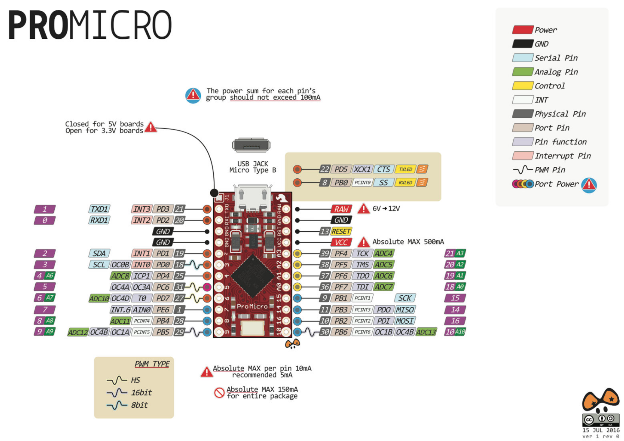
Here are the pins for the pro micro
north stream
That is odd, I think the Pro Micro uses the same chip.
wind drift
pro micro uses 32u4 chip
north stream
Ah, slightly different chip.
wind drift
Other question. I am using a LDR photoresistor to detect dark/light environment
But everytime I restart my arduino the value changes quite a bit
530 when light is on
390 when light is off
Next time it's 780 and 600 or so
cedar mountain
Are those values in the ballpark for what you'd expect for the resistor circuit you have, i.e. a few volts on the ADC?
wind drift
How do I get a stable value out of it?
I have it connected like this
to 3.3v
10k resistor
ah no sorry
20k resistor
don't have 10k here
cedar mountain
Does it actually seem to be reacting properly to the light, or are the values more random?
stuck coral
Are you sure you're putting the exact amount of light on it in each test? Willing to bet its working OK if its wired the way you say.
cedar mountain
That seems reasonably consistent, if the amount of light in the open condition is within +/- 5% from trial to trial.
There's also sometimes a second or few of time delay in the dark condition before the reading stabilizes.
stuck coral
I also think the amount of light being put on it is changing slightly in the room, even changing when you move in the room which changes how the light travels and reflects. When you touch it it will move slightly. Light is finicky. And the voltage from your regulator may change the slightest bit depending on temp which would more so amplify any changes. Idk how noticable any of this would be though
wind drift
hmm okay I had put my on/off treshold to 425 earlier (covered = 350, open = 500)
Then I restarted and it was covered = 300, open = 400
cedar mountain
Does it make sense for your code to do a self-calibration on bootup, i.e. take a reading and assume that it's uncovered on power up, then set the threshold from that? A fixed threshold is going to be fragile depending on whether you have a sun-lit window in the room or not, etc.
north stream
Alternatively, make it adaptive, so if the value changes X counts in Y time, it's considered a transition, but slower changes are not
mellow tusk
To continue @north stream ‘s thought. Apply a moving average to the values. Then check the result. That way you can filter out any noise. Also look at writing a dead zone near the turn off and turn on point. As an example. If the value drops below 80 turn off. But don’t turn back on until the value is above 100. This would stop flickering when near the dividing line.
stuck coral
You mean hysteresis @mellow tusk ?
pine bramble
why isnt my servo spining when i turn my encoder?```cpp
int counter = 0;
int currentStateCLK;
int previousStateCLK;
previousStateCLK = digitalRead(inputCLK);
if (currentStateCLK != previousStateCLK){
if (digitalRead(inputDT) != currentStateCLK) {
counter --;
if (counter<0){
counter=0;
}
 } else {
   counter ++;
   if (counter>180){
    counter=180;
   }

 }
 rotate.write(counter);
}
previousStateCLK = currentStateCLK;
}
pls ping if u know
stuck coral
@pine bramble would use an inturrupt to start, did you get this code from someone?
pine bramble
yes
Here's all of my code ```cpp
#include <Servo.h>
#define inputCLK 6
#define inputDT 7
Servo Claw;
Servo Wrist;
Servo Elbow;
Servo rotate;
int counter = 0;
int currentStateCLK;
int previousStateCLK;
void setup() {
pinMode(A0, INPUT); // sets the digital pin 4 as input
pinMode(A1, INPUT);
pinMode(A3, INPUT);
pinMode(inputCLK,INPUT);
pinMode(inputDT,INPUT);
previousStateCLK = digitalRead(inputCLK);
Claw.attach(3); // attaches the servo
Wrist.attach(5);
Elbow.attach(10);
rotate.attach(11);
}
void loop() {
int ClawA = analogRead(A0);
int WristA = analogRead(A1);
int ElbowA = analogRead(A2);
int ClawAn;
int WristAn;
int ElbowAn;
ClawAn = map(ClawA, 0, 1024, 0, 180);
WristAn = map(WristA, 0, 1024, 0, 180);
ElbowAn = map(ElbowA, 0, 1024, 0, 180);
Claw.write(ClawAn);
Wrist.write(WristAn);
Elbow.write(ElbowAn);
if (currentStateCLK != previousStateCLK){
if (digitalRead(inputDT) != currentStateCLK) {
counter --;
if (counter<0){
counter=0;
}
 } else {
   counter ++;
   if (counter>180){
    counter=180;
   }

 }
 rotate.write(counter);
}
previousStateCLK = currentStateCLK;
}