#help-with-arduino
1 messages · Page 36 of 1
 north kelp
 rough geyser
yep, I when I learned that it was called kebab case I was like oh-that-makes-so-much-sense 😛
I'm on version ...
1.8.5
north kelp
How to include from subfolder of sketch folder - Page 2
rough geyser
but I launched the actual IDE and see that there's an update available
aaah, and yeah I'm using vscode so I may be hitting the same issue
reading
trying the src folder ...
it worked!
north kelp
TL;DR:
Try moving your melody-player subfolder to a new subfolder called src, at the same level as your sketch.
Then do #include "src/melody-player/MelodyPlayer.h"
rough geyser
👏
north kelp
I learned something.
rough geyser
nice, it feels a bit weird since the ino is part of the source, but as long as it works I can roll with it!!
thanks for the help ⬆ 5⃣
north kelp
I wanted to see you get this working, as it's helped me factor out reusable parts of my Arduino code, and slim down my sketches.
rough geyser
cool, I'll def let you know once I'm done abstracting. I prob won't be done tonight, but I already have the code up on a public repo here: https://github.com/chris-schmitz/tone-without-delay

GitHub
Working through tone without delay on arduino. Contribute to chris-schmitz/tone-without-delay development by creating an account on GitHub.
and eventually I'm going to need to do a ton of cleanup and abstraction on the larger project that this is a proof of concept for: https://github.com/chris-schmitz/pegasus
GitHub
Proof of concept for the pegasus project to test the combination of break beam and RFID sensors. - chris-schmitz/pegasus
all of the sketches in that big project are messy, but they're all prototypes and proof of concepts so I'm not sweating it too much yet
north kelp
Also, I think adding #include "Arduino.h" near the top of MelodyPlayer.cpp may fix the missing Serial complaints.
rough geyser
👏
trying that
bc that would be very helpful
nice!! yeah that did it 🎉
always nice to see green at the bottom of the output window 😛
north kelp
This is dated, but helpful:
https://www.arduino.cc/en/Hacking/LibraryTutorial
 pine bramble
@north kelp RE: the other day discussion. I did find an electronics course after all. Starting on June 20th
north kelp
Yeah, which MIT course is that? I might take that some time!
@rough geyser I've been meaning to try Arduino in VS Code. I've just been putting it off.
pine bramble
Circuits and Electronics 1: Basic Circuit Analysis still considering if I'm taking the 2nd one at the same time or not
Seem to talk about the same subjects has the circuits course at my local university (kvl/kcl/thevenin/norton/digital abstractions/etc)
My local university only offer in-classroom course during the morning so I can't attend
Still considering wheter I'll pay to get graded or not. Maybe the 1st one will be the "trial"
rough geyser
@north kelp it's def worth trying, especially if you're already in vscode for other stuff. I'm a web app dev in my day job so I already have vscode decked out the way I like it, so switching to another ide that doesn't have all of my regular tools is rough
for the most part vscode's arduino extension is pretty good
buggy sometimes, but not horribly so
north kelp
The secondary benefit of paying for me would be that it would motivate me to commit to and finish the course.
pine bramble
You have to pay to access the videos after the 5 weeks too... so it's a difficult decision. On the other hand if there is any English to write I'm not fluent enough in it to write domain-specifics sentences
I would probably not pass the English test for international students at the real MIT
north kelp
I know I'd enjoy VS Code for Arduino for the context-aware code completion alone.
rough geyser
definitely. It's a really sharp tool 😃 def one of my fav dev tools
pine bramble
I suppose that you can use vs studio to code arduino too? Do you still have to use the IDE to upload the sketch & spy on the serial port?
rough geyser
yeah, but the extension does that in the background
north kelp
@pine bramble Yeah, that's why I keep this around; someday I'll need these domain-specific translations.
rough geyser
you use all of the same commands within vscode and vscode uses the arduino IDE's api in the background
north kelp
I kickstarted that book. There are some available at Adafruit now:
https://www.adafruit.com/product/3189

Did you ever play Myst? Did you ever play Myst without the guide? We tried for about an hour and then realized that it was much better, and a lot more fun, if there were tips and ...
pine bramble
lol. I'm probably underestimating myself because I got tested with the TOEIC and got 990/990. Had to fight my the dean on language course to get an English course (didn't work). The dean said to me "do you realize we asks for 900 to be admitted in English litterature?" But the fact is my pronunciation is really bad
I asked them to regrade it too (didn't work either). 8 years later I'm still convinced there was an error
It comes down to "How they hell can you pretend to evaluate the ability of someone in English without testing the speaking part and the writing?" It was just listening/reading
Time to learn Chinese I guess 😃
And hindi for when I call for help
 wraith current
@pine bramble I code arduino in vscode with the platformio extension. it does all the uploading and serial ports without the arduino IDE.
 humble anchor
Can someone help me with these lines of code, I don't recognize them.
They are written for an arduino uno and I don't recognize them
" // Set analogue pins as input:
DDRC = DDRC & B11000000;
// Turn on build-in pull-up resistors
PORTC = PORTC | B00111111;"
It was stated that the "B11000000" means the binary number 11000000
 odd fjord
@humble anchor the first does a "bitwise" AND - the second a "bitwise" OR
so the first will leave only the 2 highest bits as they were set before the test
the second forces the lower 6 bits to be set
does that help?
humble anchor
Yes it does, luckily a did a bit of verilog so I understand what that means!
humble anchor
Pretty annoying that he uses those functions since they are uno specific
 granite orchid
I’m confused
Analog read is peaked at 1023 when I’m not doing anything
When I tap the piezo it actually goes down
I’m not sure what’s going on here
Do I need to hook a 1Mohm between A0 and gnd?
humble anchor
I would try that, electrical components always have a little capacitance. If there is nothing to drain the charges away they will stay there
Probably when you tap the piezo you transfer the charge to yourself
granite orchid
Yeah I see like 800 avg reading
Or sometimes it fluctuates from 0-1023 and back to 0
Like a sinusoidal wave
I’ll get some 1M tomorrow
humble anchor
You can use yourself as a resistor to test it out
granite orchid
Wuh
humble anchor
Just connector yourself between A0 and gnd
granite orchid
Using me as a resistor kind of worked
But piezo isn’t picking up anything
I’ll try again tomorrow
Thanks!
humble anchor
No problem!
What type of piezo is it?
Just a regular clock?
@granite orchid forgot to tag you
 sour tide
@patent marsh we use match so that the frequency is much more fine grained. CC[0] is used to provide the top value which is why we don't support WO[0] from TC
 north stream
Oh, cool! I figured there was reasoning behind the choice, but didn't know what it was. I appreciate the explanation, even though I didn't ask the original question.
 mild elk
My clock is still running so I guess problem solved
north stream
That was a weird one.
mild elk
Yeah
 patent marsh
@sour tide When you say “frequency is much more fine grained” what do you mean by that? Do you mean the max frequency is higher in MPWM than NPWM? Or perhaps the number of possible duty cycles is higher in MPWM?
sour tide
no, not higher. the top value impacts the duration of the full cycle
without using the CC[0] it can only be 2*16-1
for TCs
pine bramble
If I connect 3 leds, one per gpio, are they in parallel like I think?
Om trying to figure out how to connect more than 2x2V voltage drop leds on my arduino 2560
And lights them independtly
north stream
If they're on different GPIOs, they're not in parallel.
You'll still want current limiting resistors.
pine bramble
That was a stupid question sorry
I forgot gpio have a 10us time quantum between each other so they are never powered at the same time as another one
north stream
You can power them at the same time if you want. I think the limit is 200mA total through all the GPIOs.
pine bramble
Afaik arduino doesnt do parallelism. I read it's multitasking and swutch gpio off every 10 us
north stream
I think the GPIOs are latching, so even though they're addressed in groups of 8, they stay on while the CPU is off doing other things.
pine bramble
So even if you tell the code to power all gpio arduino will switch between active ones 100000 times per second
It would require some tests I guess
Not that it matter much because I cant see them blinking above 57hz
north stream
I've had oscillocopes on GPIO pins on several occasions and I haven't noticed them oscillating when they're turned on.
pine bramble
So Ill have to be cateful with the blinking then so I dont get past 5V?
Ie: never have more than 2 gpios on at the same time?
So they each get 2.5V
north stream
No, the voltages don't add, the currents do.
pine bramble
So if my 54 gpios are on they all get 5V?!
north stream
So you'll need current limiting resistors for each LED to absorb the difference between the 5V from the I/O pin and the 2V the LED needs.
Yup, they all get 5V. However, you shouldn't draw more than 200mA at once (so if you're running 10 LEDs at 20mA apiece, that's all you can have on at a time).
pine bramble
Is there an electricity law that explain this?
north stream
I often run my LEDs at much lower current (at 1 or 2 mA apiece, you could have LEDs on all 54 GPIOs on at a time).
It's basically Ohm's law and Kirchoff's rule.
pine bramble
Does it matter to blink them at 60hz to save power or since the gpio is powered it wont matter?
north stream
That's another approach, you can turn on LEDs a few at a time, and switch between them so they aren't all on at once. If you switch fast enough, they'll appear to be lit continuously.
It boils down to a choice of lower current all of the time or higher current part of the time, to achieve the same brightness. I tend to go with lower current because it's easier.
pine bramble
Yeah the limit is 57 times per second for my brain. Cant see them blink at this point
For LED i should use the worst case for the resistor right? Ie: maximum voltage drop from datasheet(2.2V) and the minimal range they give on the datasheet(16 to 18ma) so 16 right??
Minimum voltage drop(1.8V) i mean...
north stream
Worst case is the minimum voltage drop (often about 2V for red LEDs) because that's the maximum voltage across the resistor. If you don't need full brightness (like I said, I don't run my LEDs hard), you can use less current.
pine bramble
So 200ohm it seems then
north stream
Right, that'll give you 16mA, which is safe, but pretty bright.
pine bramble
I need to experiment with ohm values to see what brightness I like
north stream
It'll let you light 12 LEDs at a time at that current.
You might be surprised, just a few mA is often plenty.
pine bramble
Thinking about getting ultrabright white leds and UV leds toi
north stream
For some of those, you might want to go to a driver transistor or an LED driver chip.
The LED driver chips are nice, they do the current regulation for you, and some will also multiplex LEDs as well, letting you control dozens of LEDs with a single chip.
pine bramble
I heard I need eye protection for those leds thouhht?
north stream
For the ultrabright and UV ones, it's probably a good idea.
pine bramble
What kind? I ask the clerk at the electronics store? Or same kind as when you look at the sun during an eclipse?
north stream
For indicators, I generally run them fairly gently (a 1k resistor will give about 3mA). For cosplay, I tend to use LED drivers and run them brighter.
pine bramble
It's mostly to get a quick feedback from sensors atm
north stream
I think a solar viewer would be overkill, but ordinary sunglasses with UV blocking seem like they'd be fine unless you're going for high power, staring into them, or focussing the light with optics.
pine bramble
Ie: light led 2 when sensor detects lighted led 1 next to it. Or output temperature range in "bits leds"
north stream
I have some eclipse viewing glasses they're REALLY dark.
Yeah, that's what I think of as "indicators". For those, I generally just use 1k resistors and don't worry about it.
pine bramble
Ie: for humidity 8 leds would be sufficient so 8 bits + 1 for error
Of course I might as well use a cheap 2 lines lcd screen that uses BCD
I want to experiment with multiple sensors and seeing the arduino reacts
north stream
Those little LCD displays are really appealing for simple reporting. It's easier to read "T1 = 72°F" than °•°°•°°°
I love playing with sensors and seeing how they react to things.
pine bramble
Id like to make a rc car that runs away when it detects me :)
north stream
Oh, that would also be fun for little children and pets, I'm guessing.
pine bramble
Robots in sims 3 have an afraid of humans trait chip would like to simulate it for the lolz
north stream
I like it!
pine bramble
What do you guys use to make enclosures? 3d printing with a cad software??
Ie: I wonder if it's cheaper to buy an rc car at toyrus and replace the innards or buy a kit since I akready have pi2b+ and 2 arduinos
patent marsh
@sour tide So if you only use TC you only have 32 possible duty cycle levels?
north stream
I like to buy toy cars at yard sales and thrift stores.
sour tide
no, the duty cycle can be anywhere between 0 and top
patent marsh
Or rather the maximum length of the period is .032 (s, ms, us)?
sour tide
where are you getting the 32?
patent marsh
It seems you could just configure the input clocks differently or use a different prescaler to achieve longer or shorter periods.
Or rather .125 not .032
sour tide
you can use the input clock but that only supports divisions of external clocks. by changing top you can do any fraction of the input clock for the period
pine bramble
Just dont divide the clock by 0 to avoid creating micro black holes and collapsed matter
patent marsh
So then I’m still not really sure what you mean by more fined grain control then. It seems like even in NPWM mode you still have at minimum 8-bit resolution.
sour tide
not of the period
pine bramble
Speaking of which I heard you can unlock full 12 bits on arduino analog in? Are there bad side effects to this??
north stream
I've never heard of that. I would guess that it's either doing averaging (which would slow things down) or changing the ADC configuration (which would also slow things down), but I doubt there would be any "bad" side effects.
patent marsh
Okay so you have 7 bits resolution in 8 bit mode for period
But that’s for any given input clock
And DPLL can give all sorts of different input clocks
pine bramble
Analogread() reference on arduino site says you can change resolution to 12 bits
But they are usually not good at explaining or explaining side effects so I dont trust them
sour tide
in circuitpython we only use the TC in 16bit mode
pine bramble
Thats why i bought elegoo as my 2nd board... I disliked the starter kit book
I only understand electronics thanks to adafruit and you guys no thank to arduino
I wonder if it's allowed to include a powered gps in my adafruit package so I can see where it is :)
pine bramble
Hi. I want to power an arduino and a pi with solar power. What should I get from adafruit site?
pine bramble
I think my Pi can't draw more than 1A. So at 3.3V it would be 3.3W
Need it to go for an hour, but planning to have power-intensive parts like a camera
pine bramble
I see but the PI isn't connected directly to the panel with adafruit charger, it's used to recharge the lipo battery
ie: something like Lithium Ion Battery Pack - 3.7V 4400mAh. What matters is what comes out of them right? not the panel which is too big for what I'll put the battery in
I have a pi2b+ if it matters
 inland crag
the logic is 3.3v but I think it still needs 5v
pine bramble
So I'll need something like a powerboost 500? Sorry for all the questions I have no idea how to make this possible
And I'd like to do a "test order" from adafruit to see how long it will take to ship a lithium battery here
inland crag
the 500 in powerboost 500 is for 500mA
you could try a powerboost 1000 but the pi might complain about undercurrent
dunno
pine bramble
My pi2+ works from usb 2.0 at 500ma thought. Is there something I'm missing?
inland crag
that's surprising to me but ok
pine bramble
Well I think I get it, no matter what the solar panel and/or batteries does I have to provide 2A and 5V to the pi....
What if I want the pi and arduino to talk and ideally use the same power source?
I guess I'll have to use my phone as the "computer" then...
pine bramble
I'll continue my research then, an arduino don't have the bandwidth to process a 3MP camera...
inland crag
assuming uno
pine bramble
I have a mega 2560 too but that's too big for a rc car with a bunch of sensors
inland crag
a metro 328 is basically the same as an uno and available from adafruit
metro m0 or m4 is more powerful but probably uses more power too
pine bramble
Yeah but we are talking about a bandwidth of 192 Mbit/s pretty sure only a pi-class board can handle that
arduino isn't even 500 kbit/s
inland crag
surprisingly the m4 datasheet suggests only 24mA
for the mcu
at 120mhz
or maybe like 30
but still
let me see what the voltage regulator uses
looks like 50mA is the "short current limit" of the vreg
I assume that's some minimum requirement
but it draws a variable amount based on what it's doing
max 600mA
pine bramble
I guess what I had in mind isn't doable and I should just use 4xD rechargeables nickel batteries and find a way to supply 5V 2A throught a micro-usb cable
inland crag
I'm not 100% certain
pine bramble
Maybe something like this: "12,000mAh / 44 Watt hour external battery with dual-USB ports (1A/2A) would be better
Saw a video of someone running it from powerboost 500 (so 500ma) but he turned off a lot of hardware with a boot script
It's 4" x 4.25" x 0.75" and 312g. Could fit under the Pi/arduino there are side-by-side. But then I'd probably need better motors because of the additional almost a pound weight
I mean the battery is ideal as it already has a micro-usb 5V 2A port
 sharp sail
I have a piezo sensor in analog input (2) and a solenoid signal output in digital output (2). What I am trying to accomplish is read the “punch” of the solenoid by having the solenoid rest on top of the piezo. The issue I’m running into is since the solenoid is so quick I cannot SerialRead while I activate the solenoid. I almost need in to always be reading the piezo input while I meanwhile activate the solenoid. Is there any way to do this in the code?
north stream
SerialRead? Did you mean analogRead?
sharp sail
Yes, sorry analogRead
north stream
That is tricky, and the analog digitizer is relatively slow. Do you need the actual waveshape or just the peak value?
pine bramble
Is someone around to check my first custom circuit? I need to read dht-11
schematics says to put wires directly to it because it's on a breakout but Id rather stick it in a breadboard
north stream
I stick breakouts in breadboards all the time, works fine. If I want to haywire them later, I can use jumper wires on the header pins.
pine bramble
Doesn't seem to fit snugly
Can't find the GND on it and I only have mandaglish instructions
north stream
Did you solder header pins to the breakout board or something else?
pine bramble
It came like that in the kit, but nvm I foound the right schematic and apparently I have to use F-M dupont wires but they are stuck together
north stream
You can pull them apart if need be if they're the usual ribbon cable style, they peel apart fairly easily.
pine bramble
I had that schematic and couldn't figure out why I had 3 pins very close together and that schematic showed the gnd much farther away to the other two but I was reading the wrong thing
north stream
Most of the ones I see have Vcc and ground on the ends and data in the middle, but I've seen Vcc on the left on some boards and on the right on others.
pine bramble
Yeah it seems on the actual breakout board (it comes with a 10900 ohm resistance which is nice) the order is data vcc gnd too. Anyway time to try it
north stream
Ah, I was going to mention that it may need a pull-up resistor, but I'm guessing the one you mentioned does that job.
rough geyser
@north kelp in case you wanted to check it out, here's how the abstracted class is shaping out. https://github.com/chris-schmitz/tone-without-delay/tree/abstracting-to-class/src/melodyPlayer
GitHub
Working through tone without delay on arduino. Contribute to chris-schmitz/tone-without-delay development by creating an account on GitHub.
I got it implemented with delays, added the melodies and the dynamic picking via enums, and now I'm going to go back and add in a boolean to the method signature so I can tell it to play with or without delay
(and add in the without delay private method and logic of course)
pine bramble
You know when you buy a kit and don't pay attention and mention here you need X then you realize you already have X in that kit?
Yeah. Turn out I already have a 2 lines LCD screen
north stream
Better than the other way around.
sharp sail
I am trying to retrieve peak values, for instance, activate the solenoid x amount of times and take an average
pine bramble
Yeah tell me about it. I still haven't food that dc motor I lost. Friend told me he lost a oneplus3 in his home to make me feel better
At least that dc motor is only 2-3$
north stream
Ah, peak values are easier, you can use a peak detector circuit to catch and hold the peak value then pick it up shortly later with the analog input.
sharp sail
Essentially there is no way to do it within the code itself?
Is there some kind of delay command where I send it and it waits 3 seconds to trigger while the analog read does its thing
pine bramble
no smoke so far and the sensor seems to be warming up to more accurate values (near the ones indicated by by smart thermostat above it)
So I have a 2nd dht-11, I wonder how I would plug it to do sensor fusion from both? The breakout board seem to hint at only allowing one to be plugged in at the same time
23:45:08.277 -> T = 22.0 deg. C, H = 51.0% 23:45:11.556 -> T = 23.0 deg. C, H = 51.0% 23:45:14.823 -> T = 23.0 deg. C, H = 51.0% 23:45:18.105 -> T = 24.0 deg. C, H = 51.0% , not a great sensor but it does give a better guess than a human made-up value
thermostat says 23oC 55% but it does have a dht-22 inside afaik
pine bramble
Bah can't figure how to wire two of them... I have the GND wires on the same lines joined by a wire to the - line going to gnd on the arduino and the 5V wires on the same lines joined by a wire to the + line going to the 5V pin on the arduino
Wish fritzing had a dht11 so I could show you
north stream
You'd connect the ground wires together, and the 5V wires together, and each data lead to a different GPIO pin.
pine bramble
The Black P things are the DHT11s
I think I'm missing 2 wires, one to connect line 12 to the + rail(5V) and one to connect line 4 to the - rail(gnd)
It's my first fritzing circuit and yes the breadboard I have in front of me was glued the wrong way by me
So the one on top is on GPIO #2 and the bottom one is on GPIO #3, those are breakout boards so they have resistance so I simplified them out
 sinful saffron
the left side of the breadboard I don't believe is connected to the right (would have to move the right sensor 5v and ground to the left side)
pine bramble
Yeah so I'm missing 4 wires then to connect all the parts of the breadboard. Would it change anything if I used the right -/+ rails vs the left ones?
sinful saffron
if you don't have any extra sensors/devices, you could just put the ground to line 4, and 5v to line 12
from the arduino side
north stream
Just use the power and ground rails, that's what they're for.
pine bramble
this @sinful saffron ?
sinful saffron
yeah
pine bramble
yay seems the simplest just put red next to each other vertically on + and all the black vertically on the - line from the top
sinful saffron
madbodger is right though for when you get more complexity, having a lot of extra locations that you can pull power and ground from makes it easier than trying to split wires
(you'll want to be careful if you go crazy though, adding a bunch of LEDs or power hungry devices might put too much load on the Arduino) A few small sensors is no problem
pine bramble
Final circuit if I understood @north stream correctly
sinful saffron
yup
pine bramble
middle pin / red wire is VCC 3rd pin / black wires is GND
The library I'm using only support reading one of them, ie: static const int DHT_SENSOR_PIN = 2; so I'll have to code to be able to read the 2nd sensor
sinful saffron
just make another like static const int SECOND_DHT_SENSOR_PIN = 3
could just make it OUTDOOR_SENSOR_PIN or something too
as long as you reference it during the call
pine bramble
Yeah, seems to have issues so I'm debugging it
When you upload a sketch does it clear all the other ones off the arduino?
sinful saffron
yeah
pine bramble
So you need to upload something large or have something like a pi uploading parts of them sequentially?
pine bramble
Getting the exact same reading from both sensors which is unexpected
Ah the trappings of copy-paste 😃
pine bramble
nah, forgot to rename temperature to temperature2 after copy-paste when printing the readings
0:49:14.568 -> Sensor DHT-11(#1)T = 22.0 deg. C, H = 51.0% 00:49:14.637 -> Sensor DHT-11(#2)T = 22.0 deg. C, H = 47.0%
00:49:17.859 -> Sensor DHT-11(#1)T = 24.0 deg. C, H = 51.0% 00:49:17.893 -> Sensor DHT-11(#2)T = 22.0 deg. C, H = 47.0% makes more sense
sinful saffron
nice
pine bramble
I wonder if the inaccuracy is due to noise or something else
sinful saffron
what's the rated precision
pine bramble
+/- 2% as these are dirt cheap but the issue is that re-measure can vary by +/- 5%
And they can take 30-60secs to warm up to a change
sinful saffron
do they need time between measurement?
pine bramble
I wonder if those poor specs are due to material or huge noise
yeah the example program I have suggest 1 measurement every 4 second. datasheet says 2 to 3 seconds
And they are digital with CRC codes and begin/end transmission bytes
Of course if I needed something really good I would get adafruit's sensirion 31 in DFN package on a breakout board
sinful saffron
guess that's just the accur....(inaccuracy) of the sensors lol
pine bramble
So how does it work? They are made of a material that change property based on temperature/humidity and that change is measured by the ic chip on it?
sinful saffron
not sure, probably a material that gets more resistance the hotter it gets
then the onboard chip measures that and sends the data
pine bramble
It's not that bad considering the thermostat above my android shows 23oC and 55% humidity (it has a sensirion in it I think), but what sucks is the repeatability. Seeing it varies by as much as 4oC in 4 seconds is kinda bad
Time to code the sensor fusion
sinful saffron
just have to average it out
pine bramble
yeah, but there are more complex method like multisampling and giving more weight in the average to recent measures
But right now just averaging it will do fine
And besides since they aren't very accurate calculating the normal distribution of the noise over thousands of measure in a week then multisampling then removing the noise isn't really worth it
Basically what I mean is to calculate Measure(sensor) + N(0,u) where u is the average of the normal distribution of the noise so you can remove N(0,u) from future measures
This is a bit better: 01:11:24.125 -> Sensor DHT-11(Fusion))T = 23.5 deg. C, H = 51.5% 01:11:27.325 -> Sensor DHT-11(Fusion))T = 23.5 deg. C, H = 51.5% . Takes the last measures taken by both sensors ie: if( measure_environment( &temperature, &humidity ) == true || measure_environment_2( &temperature2, &humidity2 ) == true )
It does vary a lot less now
sinful saffron
might not make much of a difference, but take measurements at different times between sensors
pine bramble
It's kinda frustrating honestly because my hue motion sensor take temperature with 2 decimals
vs no decimal for this and it costs 30$ so it probably has 10$ of components
sinful saffron
ouch
pine bramble
Are multimeters useful on arduino? I read that since it works a bit differently than normal circuits and other gotchas the readings will probably be wrong and it's better to use analog inputs to measure voltages and amp sensors to measure amps
sinful saffron
it's not super accurate but https://www.electroschematics.com/9351/arduino-digital-voltmeter/
for voltage
if that's what you were looking for
pine bramble
Tomorrow I'll add the LCd. Which mean I'll probably have to switch the circuit to mega 2560
north stream
Should have enough pins for a pair of DHT11 and an LCD on an ordinary Arduino.
pine bramble
True but it's the messy wiring that bother me and the upside down half-breadboard. My 2560 has a full breadboard and space to make the wiring less messy. Plus I got a plastic plate for the 2560 + the pi 2b+ so I'll be able to screw both to the plate
sinful saffron
I would get an LCD board
so you only have to use a couple IO ports up
something like this https://www.adafruit.com/product/292

LCD backpacks reduce the number of pins needed to connect to an LCD. LCDs are a fun and easy way to have your microcontroller project talk back to you. Character LCDs are common, and easy to ...
pine bramble
I could probably easily add an ultrasonic range finger that is almost as easy to hook up as those 2 dht11 after I'm done installing my new speakers
Sound like an lcd board would be nice but all the stuff I got from elegoo are on boards so I'm not sure it would be compatible
ie: it's not a vanilla lcd screen
sinful saffron
could check the pinouts and see if it's .1 inch spacing and such, though you might be correct
pine bramble
Let me get a picture, I have a question about one of the sensor I have anyway which seems odd
LCD screen at the bottom and some board at the top with ieee/firewire port?? and some kind of usb??
lcd seems to be lcd 1602 with pin header and that chip at the top is a power supply module...
north stream
No, not IEEE/Firewire, looks like a breadboard power supply.
Looks like a standard HD44780 type LCD with LED backlight.
pine bramble
I sede. https://www.adafruit.com/product/772 would be a nice upgrade (lcd+backback module+scrollable text using the joystick on the board) at 19.95$ and I guess top of the line would be Nokia 5110/3310 monochrome LCD + extras at 10$ which seem to be another species of LCD

This new Adafruit shield makes it easy to use a 16x2 Character LCD. We really like the Blue & White 16x2 LCDs we stock in the shop. Unfortunately, these LCDs do require quite a few ...
The nokia lcd sure seems nice
north stream
Or 128x64 for $6 https://www.goldmine-elec-products.com/prodinfo.asp?number=G22946
Or if you want something really good looking https://www.noritake-elec.com/products/vfd-display-module/dot-matrix-graphic-display/gu-3000-series
 pulsar charm
I fancy the 128x64 SSD1306 i2c OLED screens
4 pins and you could easily go jumperless
if you are using an ESP
 barren scaffold
Re: temperature sensors, I’d have a hard time believing any inexpensive sensor could get 2 real decimals of precision. Maybe with an independently calibrated thermistor, but why would a company put effort in that unless it was really easy to calibrate.
pine bramble
@north stream replacing my MCP IC fixed it. guess i'll document that old one being partially defective and throw it in my box.
north stream
Makes sense. It's annoying having broken ICs, but wise to mark them so they don't do something confusing in the future.
 lean jetty
Hello
lean jetty
Anyone around to help me?
inland crag
Ask your question, and if people have an answer they'll answer
lean jetty
I got the hallowwing box and I am setting it up and getting this when I try to upload
Sketch uses 10552 bytes (4%) of program storage space. Maximum is 262144 bytes.
java.io.IOException: Cannot run program "{runtime.tools.bossac-1.7.0.path}/bossac": CreateProcess error=2, The system cannot find the file specified
at java.lang.ProcessBuilder.start(ProcessBuilder.java:1048)
at processing.app.helpers.ProcessUtils.exec(ProcessUtils.java:26)
at cc.arduino.packages.Uploader.executeUploadCommand(Uploader.java:129)
at cc.arduino.packages.uploaders.SerialUploader.runCommand(SerialUploader.java:383)
at cc.arduino.packages.uploaders.SerialUploader.uploadUsingPreferences(SerialUploader.java:197)
at cc.arduino.UploaderUtils.upload(UploaderUtils.java:77)
at processing.app.SketchController.upload(SketchController.java:732)
at processing.app.SketchController.exportApplet(SketchController.java:703)
at processing.app.Editor$UploadHandler.run(Editor.java:2070)
at java.lang.Thread.run(Thread.java:748)
Caused by: java.io.IOException: CreateProcess error=2, The system cannot find the file specified
at java.lang.ProcessImpl.create(Native Method)
at java.lang.ProcessImpl.<init>(ProcessImpl.java:386)
at java.lang.ProcessImpl.start(ProcessImpl.java:137)
at java.lang.ProcessBuilder.start(ProcessBuilder.java:1029)
... 9 more
An error occurred while uploading the sketch
inland crag
You gotta install samd arduino
 lean jetty
inland crag
lean jetty
inland crag
¯_(ツ)_/¯
inland crag
I don't think that's it. Just tap reset once to get out though
lean jetty
red light does not fade anymore but still opens HALLOWBOOT when pluged in
Is there a factory reset? Now the red light is fading again
 burnt island
scroll up in the bottom black box. There should be more details father up
 brazen idol
There's nothing more in the black box ??
pine bramble
Can I use serial handling in custom functions called from loop() or is this reserved to loop() ? ie: is serial handling by loop() also scoped in methods it uses
north stream
You can call Serial methods from anywhere, but the UART service routine is called when loop() exits, so if you stay in the external routine and never return to (or exit) loop(), things may not work as desired.
lean jetty
I have tried on 2 computers to see if I could fix the problem I posted. Anyone think I can format this hallowing and factory reset it
odd fjord
@lean jetty have you tried uploading a sketch to it. It sounds like the bootloader is ok. What are you trying to do with it?
lean jetty
Trying to get it to display the eye again
I want to custom make my own eye for it
it I got it to display something now
its text booted up in CIRCUITPY drive
odd fjord
This guide shows you how to reload various eyes.

This is Hallowing..this is Hallowing... Hallowing! Hallowing!
pine bramble
I'm starting to really dislike arduino ide, and gcc always crashed until I downgraded my avr tools
I heard you can code arduino with vscode, is there something not included from the arduino ide?
 crystal mesa
Last I'd used it (and it looks like it's still this way) VS Code uses an extension that works with the Arduino IDE tools in the background. You're basically using VS Code as a much better editor. I found it a little clunky to work with and went back to the Arduino IDE, but then again, I'm the kind of guy who prefers NotePad++ to VS Code. I WANT to like VS Code, I just find it...a little more involved, I guess, than I want.
 toxic flare
Sublime Text also has a plugin for Arduino
._.
Ok, so my messages keep getting removed because the censorship filter is super-duper censor-happy. What I'm saying is that the Arduino IDE is bad.
 worldly aspen
hey guys, i am transmitting a constant stream of 12 bit data to my arduino thru uart. I want to detect if the uart has stopped receiving the data, any ideas ?
humble anchor
Take a look at the RX and TX Leds @worldly aspen
Don't know if this is answers your question but it seems like you want that
Depends on the arduino/uart if they have leds installed
 blazing willow
Been trying to get a grasp on using nesting loop in FASTLED library. I've read over the documentation but I think my reading disorder is causing me to miss how to proper us nesting loops with fadeToBlackBy(). Anyone willing to talk with me about this. I absorb information a lot better by talking things out to understand them.
north stream
I might be able to after I finish this lab.
mild elk
I have a problem regarding interrupts: in this code when I press the button attached to pin 2 and debounced with 0.1uF ceramic cap, it ofter ends up triggering twice making it very unpleasent to use. All suggestions are welcome. Quick responnse much appreciated.
north stream
You might want to use a software debouncing library, add a series resistor, or use a debouncing chip.
north stream
I don't think the Bounce2 library (which is the one I use) is very large.
mild elk
ok, i'll check it out then
mild elk
wait, but how do I debounce an interrupt with this?
north stream
It's trickier with an interrupt.
 simple horizon
Why is the itsy bitsy m0 so slow on arduino?
north stream
Mine's really fast, I dunno.
simple horizon
It seems slow compared to the huzzah esp32 feather
north stream
Oh, I thought you meant compared to Arduino.
 safe shell
@simple horizon It's apples and oranges because the architectures are different, but just start with the Itsy Bitsy M0 being 48 MHz, and the ESP32 being (dual-core) 240 MHz. Much more RAM in the ESP32 also.
simple horizon
I figured it was probably me just being dumb
safe shell
No, it's rarely simple. So many factors influence performance, and they depend on the characteristics of the program, peripherals in use, features of the processor, etc.
granite orchid
Progress! So piezo works, but simple thresold won’t do
I set it as if(input>thresold) Keyboard.write(“d”);
But I always get multiple d’s so
I have to find the peak of each impact somehow
Was hoping that the decay would be taken care of if I set the threshold fairly high but no
north stream
It's a tricky problem to both find the peak and debounce the signal while at the same time not delaying the detection or monopolizing the CPU. I might look at something like an analog peak detector circuit with a slow(ish) decay, along with some hysteresis (either analog or digital) or a holdoff delay.
mild elk
I'm trying to get alarms to work with DS3231 with no effect. Is there something I should know? Or something I'm doing wrong?
north stream
There are a few possibilities. The first one I think of is that the INT output is open collector: if you're looking to get a logic level from it, you'll need a pull-up resistor.
mild elk
I have an input configured as INPUT_PULLUP
I can post my code if that's helpful
@north stream
north stream
Instead of posting your code, explain what works and what doesn't. What did you do, what did you expect to happen, and what really did happen?
mild elk
I looked into DS3231 datasheet and wrote hours and minutes to alarm 2 register and enabled it in control register as well as interrupt output. I expected it to fire an interrupt when current time matches time stored in alarm 2 registers but nothing happened.
@north stream
north stream
Ah, good, that's more information. Does the state of the interrupt output change? What are you seeing in the flag register?
mild elk
give me a sec, have to read it first
10001010
^ 0x0f register contents
interrupt does not trigger, but I can't confirm if it changes because I dont have a scope. If You know any other way to check it let me know
mild elk
It's low, so I guess it's my code's fault
north stream
Yeah, if you're looking for a high-to-low transition, you have to start with it high (unasserted)
north stream
It should go high when you clear it: have you tried clearing the alarm bits in the flag register?
You'll probably have to set up the alarm mask bits as well
mild elk
I'm doing all this in my code
north stream
Huh?
mild elk
I clear alarm bits in flags register and set alarm mask bits
north stream
But the interrupt output stays low?
mild elk
Yes
north stream
Basically, that's your smoking gun: as long as that output is low, you still need to do some setup.
mild elk
I'm wondering what else might be missing
north stream
You showed the flag bits as 10001010 which isn't what you want (A2F is set)
OSF is set too, which is curious.
mild elk
I changed my code a bit and now it is high but never goes low
north stream
Ah, that's a start. It should go low if the alarm enable bit is set, along with the matching alarm flag (and INTCN is 1).
mild elk
Sorry, I suddenly had to leave my home and I'm not sure when I'll be back, but I'll let You know when I can get back to it
 sweet iris
Does anyone know a way to do touch detection on a Feather Huzzah esp8266? I tried putting one strip of conductive tape on 3.3v and the other on ADC, but that left the pin always at 1024 no matter what. When I added a small resistor, it floats around 70 to 100, but doesnt change when I touch the two strips
Oh, I think I should post this of #help-with-projects
pulsar charm
So I've found a code that can do an i2c scan and give you devices currently connected to your i2c bus (dec, hex)
like super useful when you just got a sensor from a stranger and adafruit is down
The code is here btw: https://github.com/todbot/arduino-i2c-scanner

GitHub
Simple Arduino I2C scanner as described at http://todbot.com/blog/2009/11/29/i2cscanner-pde-arduino-as-i2c-bus-scanner/ - todbot/arduino-i2c-scanner
But I wanted to make it even more useful as a kind of universal tester I could leave at my local makerspace, so people could just plug an i2c device and get the address on the fly (via a display or some sort) as opposed to Serial.
The problem is that when an i2c display library is used the scanner output becomes garbage (you can try it)
Will running the display on SPI help instead?
burnt island
is a finger enough to bridge two strips of tape? I don't think it will make a short reliably
mild elk
@north stream I finally did it! Thank You so much for Your help! Now I have to figure out why after pressing a button to turn off an alarm it goes to menu instead of clock screen
mild elk
and why setting page says enabled when variable is set to 0
@granite orchid i<NUM_PIEZO>;
maybe?
granite orchid
Sorry i dont get it
mild elk
it says You got something missing in that line before ;
north stream
What is NUM_PIEZO set to?
burnt island
that'll do it. No semi-colons on #defines. There lies madness
sweet iris
@burnt island It worked when I used the A0 pin of a Wemos D1 Mini, but I had to move to the Feather Huzzah esp8266 so it could be battery powered
north kelp
@granite orchid I do that all the time. I will sometimes type semicolons after every line out of habit. 😸
mild elk
I have this very weird issues where variables are not set correctly in ISRs even though they are declared as volatile. Any ideas?
north kelp
Hmmm. What's your code look like, @mild elk ?
mild elk
Can't paste it because it's almost 600 lines long
@north kelp
Take Your time I guess
mild elk
328p
north kelp
Arduino UNO?
mild elk
Yes
north kelp
The Arduino programming language Reference, organized into Functions, Variable and Constant, and Structure keywords.
According to the official Arduino reference on attachInterrupt(), you can use pins 2 and 3 for interrupts on your UNO.
mild elk
I have read that before and my code follows all guidelines listed there
Please ping me when You reply
north kelp
@mild elk Hmmm. I use ISRs occasionally, but very lightly.
I'm suspicious of attachInterrupt() and detachInterrupt() inside an interrupt service routine.
pine bramble
Guys, I am using a 4x7 segment display. My plan is to use resistors for all pins except 12, 9, 8 and 6. However, could I use resistors only for the Digit Pins? Then I would only need 4 resistors.
because I learned that it doesn’t matter which side a resistor is on.
I have the Bx model
 solar sail
The issue with doing that is that since there's just the one resistor, turning on more segments in a digit will make that digit dimmer as it will drop more voltage because of the higher current the LEDs are pulling
north kelp
@mild elk I'd consider refactoring it so that all the attachInterrupt()s happen once in setup(). Then, inside a called ISR, I'd manipulate a state machine.
pine bramble
I saw someone do it that way and he had the Ax model. he would also suffer from that issue right?
mild elk
@north kelp so You suggest to avoid re-attaching interrupts in yhe main code?
Oh god it will make it so much more complicated
north kelp
@mild elk I may be just shy of what you're trying to do with interrupts, and it may be OK.
mild elk
This code is a clock with DS3231 and 128x64 oled. You can try it out to get the idea
north kelp
But in much of your ISR code, you're changing what midBtn does by attaching functions. My approach would be to attach a midButtonISR() function, and in that modify a volatile uint8_t midButtonAction and volatile bool midButtonPressed. Then in loop(), I'd check for midButtonPressed, and use midButtonAction to decide what to do.
Also, I'm looking at volatile in the Arduino reference:
https://www.arduino.cc/reference/en/language/variables/variable-scope--qualifiers/volatile/
The Arduino programming language Reference, organized into Functions, Variable and Constant, and Structure keywords.
“If the volatile variable is bigger than a byte (e.g. a 16 bit int or a 32 bit long), then the microcontroller can not read it in one step, because it is an 8 bit microcontroller.”
mild elk
My variables are never bigger than 100 so...
north kelp
Yep.
Could probably change them all to uint8_t.
Not sure if that will solve the immediate problem, but could prevent future ones. 😃
mild elk
🤔 I guess it wouldn't hurt to try that out
north kelp
Basically, you're using attachInterrupt() inside ISRs to create a state machine, but I think that the same state machine could live in volatile variables assigned maybe to enum states, which feels to me like it's a lighter effort inside an ISR.
mild elk
"enum states"? Never heard of that before
north kelp
Most Arduino projects will benefit from using a state machine with enum. This tutorial shows how to create a simple one.
mild elk
Thanks, I'll have a look into that
Using uint8_t didn't help, so I guess I'll have to rewrite my code third time
pine bramble
How do I know the current without resistance? 5 Volts
mild elk
Go to ohmslawcalculator.com
mild elk
You need to know at least two values
So to calculate current without resistance You need to know power
pine bramble
Like wouldn’t that mean that Current could be anything?
mild elk
Technicly yeah
pine bramble
Nevermind, 5 = I * 0 which is impossible
But with 0 resistance there is no V required then?
mild elk
With 0 resistance there is an infinite amount of current, but this is impossible
pine bramble
Yes. I am kinda confused how it works
mild elk
Tell me exactly what do You need to calculate
pine bramble
I was just thinking how much current there would be flowing if I didn’t use resistor for a 30mA rated device
With Voltage being 5V
mild elk
As much as Your power source can deliver
But You still have wire/connection resistance which might be low but is never 0
pine bramble
how do I know how much current it delivers?
mild elk
Depends on what Your power source is
pine bramble
Arduino Uno
 delicate zealot
Hello Everyone, I'm new here, I'm driving a tank-style crawler with Aruino Uno and Adafruit Motor Shield V2, I know it has output for 4 DC motors... However, I only found code online (I'm not a coder) for using M2 and M4, but I have 4 motors... So what I did was I hooked the 2 left motors to M2, and the 2 Right motors to M4.
Now, I don't know if that basically splits the voltage going out or not, but I do feel my tank is underpowered.
Do I need to mess with the code and duplicate M2 and M4 to say M1 and M3? So every motor has its own outlet?
I also just read, apparently this shield V2 only goes so far in Amps, and maybe my motors need more, was the motor shield designed to drive only small DC motors?
These are the motors and tank I bought from amazon: https://www.amazon.com/gp/product/B07F66H5ZG/ref=ppx_yo_dt_b_asin_title_o00_s00?ie=UTF8&psc=1
Thank you all!
sinful saffron
not sure about power but it looks like all 4 motors should have separate control
what voltage do you have hooked up?
delicate zealot
12V DC on the Shield, 5V on the Arduino.
sinful saffron
what's the motor rating if you can see it?
the shield looks like it can supply 1.2 amps per motor channel (4 of them)
if the motors pull less current than 1.2 amps, than they would be the limiting factor
pulsar charm
any recommendations for circuits/components that can lower a 12V signal to a 5V for IO input?
Yes there's the trusty voltage divider, but I've been hearing a lot about op-amps and zener diodes that can do something similar too
looking for something that can handle it with minimum hassle
north stream
The appropriate techniques also vary depending on whether it's an analog signal or a digital signal, and if it's digital, whether it's wired-or (like I2C) or push-pull (full voltage like CMOS or asymmetrical like TTL).
pulsar charm
its just a digital signal @north stream
But holy crap, I did a bit of reading about and found out the the 3.3V -> 5V bi-directional logic converters are able to handle 5v - 12V current
and I tried it and it works, I'm just extremely surprised there isn't an elegant solution about it. It seems like the CMOS CD4050 has been around for 40 years
pine bramble
Hello. I am trying to use shift registor and 4x 7 segment display. To display 0, the binary data needs to be 00111111. I am trying to display this to only the first digit. This is the code:
int latchPin = 9;
int clockPin = 10;
int dataPin = 8;
int digit1 = 2;
void setup(){
pinMode(latchPin, OUTPUT);
pinMode(dataPin, OUTPUT);
pinMode(clockPin, OUTPUT);
pinMode(digit1, OUTPUT);
}
void loop(){
digitalWrite(latchPin, LOW);
shiftOut(dataPin, clockPin, MSBFIRST, 63);
digitalWrite(latchPin, HIGH);
digitalWrite(2, HIGH);
delay(1000);
}
however, the whole digit lights up, including the DP and G
mild elk
Use spi
You connect arduino mosi to register data in, arduino sck to register clock and any pin of Your choice to latch. Then just send out the data using spi libary
pine bramble
Oh so i used wrong pins?
pulsar charm
oh by the way I've made an i2c benchtop tester to help you determine the mysterious i2c addresses. Would be happy to share if anyone finds it useful
mild elk
Honestly I have never used shiftOut
Is it some kind of library?
mild elk
Dont bother with dedicated libaries, just use spi
It's going to be faster, because arduino has dedicated hardware spi interface and it takes less cpu time to send out spi data than to bit-bang it
pine bramble
Im using this https://youtu.be/cHA-fwiA4Qo because we need to use 595 to control the display

In this 3rd part of our 7-segment to arduino connection walkthrough tutorial we use a 595 Shift register to display the numbers. Walking through all the step...
Mine js a bit different as i use 4x7 segment display so i only connected the segments to the 595. Or do I need 2 595’s?
pine bramble
4 digits
mild elk
How many pins does it have? Is it a common anode or common cathode? Come on I need some more informations
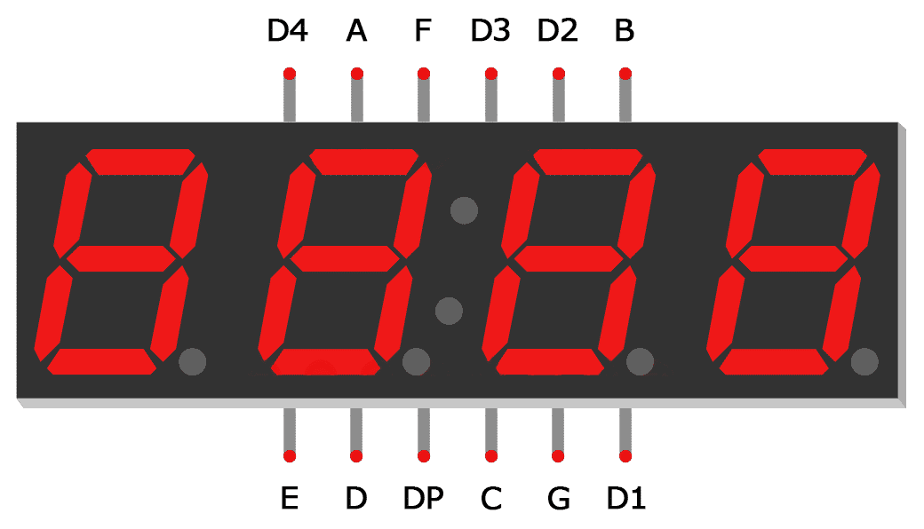
Does it look like this?
@pine bramble
pine bramble
Yes
The digits are connected to arduino and the segments are connected to the register
mild elk
What about resistors? Arduino can't supply enough current to power whole digit
And I still don't know if it's cc or ca
@pine bramble
I assume You have a breadboard
Get Your display, connect one segment to ground and one digit THROUGH RESISTOR to +5V. Resistor should be at least 220 ohms
Tell me if it lit up or not
And ping me when You reply
north stream
You can use shiftOut (it's useful when the SPI pins aren't available or for pin use reasons). However, I think you need to change your latch code. And yes, it matters whether the display is common cathode or common anode, but since it lit, it's probably wired correctly. Current limiting resistors are indeed a good idea.
mild elk
I just built clock's seconds display just with 74 series chips and 7 segment displays and set functionality and honestly it was really fun. If You want to learn about logic ICs and how to use them I highly recommend doing something like that.
I plan to expand mine to have minutes and hours displays as well as change the display to VFD tubes
This took two breadboards and 9 ICs though
But I like it becaues there is no coding - You build it and it just works
I know 4026 would be better but I used what I had lying around
pine bramble
@mild elk it is CA, i use 1K resistors
pine bramble
Yes
mild elk
Ok, so now check wiring of hc595
Remember that reset is active-low
pine bramble
Yes it is
mild elk
And You need to connect all inputs to either 5V or ground to have it work
Make sure no pins are floating
pine bramble
I did that and It’s wired correctly
mild elk
Then it must be something with Your code, not the wiring
pine bramble
I believe so too. The display worked fine before and i double checked the wiring with the shift register
i used it before without sift register
mild elk
Ok, now do something like this: connect hc595 sck to arduino pin 13, serial in to pin 11 and latch to pin 9
pine bramble
I had the same idea and already tried this. Also updated the code, same result
mild elk
You tried spi?
mild elk
Then it's not spi
You just changed the pins
That's not how it works
Give me a sec I'll write some code for You
pine bramble
i was hoping it was like that lol.
mild elk
Nah, You need to tell the arduino to use hardware spi interface
void setup() {
  pinMode(9, OUTPUT);
  digitalWrite(9, LOW);
  SPI.begin();    //initialize SPI library
  SPI.setBitOrder(MSBFIRST);  //set SPI bit order
  SPI.setDataMode(SPI_MODE0); //and mode
  SPI.transfer(B00111111);  //send out Your data
  latch();  //update output latch
}

void loop() {
  //no need to do anything here
}

void latch() {  //update output latch on 595
  digitalWrite(9, HIGH);
  digitalWrite(9, LOW);
}
@pine bramble
rough geyser
@north kelp I know you said you were interested to see the final class abstraction of the procedural tone-without-delay proof of concept I was working on. I just finished so I thought I'd shoot the repo over: https://github.com/chris-schmitz/tone-without-delay
GitHub
Working through tone without delay on arduino. Contribute to chris-schmitz/tone-without-delay development by creating an account on GitHub.
thanks again for your help the other day 🙇
and vid of it working. I posed about this in the audio help channel, but I'm not sure if you watch it or not so I thought I'd shoot it here too: https://vimeo.com/343229038

I got tone without delay "working" before, but it was in a procedural script. The sketches for the prototype are getting big enough that I def don't…
mild elk
Also, if anyone has an idea how to make my 74 series design simpler, I'd be glad to hear Your ideas
Just remember - no microcontrollers
I can post (hand drawn) block diagram if someone would be interested
Ping me if You reply
north stream
The usual approach is something like a 7448, but I'm guessing you're doing segment decoding with gates?
wraith current
@rough geyser nice work. goood looking code.
north stream
Maybe pseudo-BCD counting with a 7490 (seconds) and 7492 (tens of seconds)?
mild elk
I'm using hc393 counters and ls247 decoders
mild elk
4060 for 2Hz clock, hc73 for dividing it by 2 as well as switching to manual clock when setting. 556 for debouncing and hc08, 02 and 00 for adjusting signals and operating blanking input to blink digits when setting
@pine bramble if it doesn't work/generate much heat
Try to replace it wit new one
Just make sure one more time You wired it right
pine bramble
i took a pic but the cables are kinda messy. Im not sure if you can figure out how its connected from it
mild elk
I guess I could try
pine bramble
But anyways here it is: the Digit pins are connected directly to the Arduino, 2, 3, 4, 5. And the segment pins are connected to 1K resistors. Then with more wires I connect the other part of the resistor to pins that represent 8 bits.
Output Enable is connected GND, Master reset to +, ground to ground, extension also to ground.
rough geyser
@wraith current thanks 😃 I'm still fairly novice when it comes to cpp, but I'm getting a lot more comfortable with it. It's nice to get to the point where I can code and think at speed with it similar to my primary languages
north stream
What is "extension"?
It might be worth doing a loop like setting DIN low, making a short clock pulse, waiting a few hundred milliseconds, and repeating and watching the display, then setting DIN high and doing it again. You should be able to see the data propagating through the shift register, segment by segment.
Perhaps a too-short latch or clock pulse is causing problems, or there's an overload somewhere.
mild elk
@pine bramble output enable is active low
Also I told You to not connect segments directly to arduino
You should use p-channel mosfets for that
If Your display is common anode and You had output enable high which brings all outputs low then no wonder all segments lit
ALWAYS CHECK THE PINOUT
if You did what I suggested You could have saved us a lot of hassle
 pine bramble
i just got a 6x2 LCD to do hello world now it only outputs jibberish lol
seems to be faulty wire, trippy
broke again, think its time to take a break.
 granite depot
Hello friends. Need some help turning off the AP mode on a feather hazzah. Currently it's connected as client and broadcasting and AP.
Followed the Adafruit IO tutorial to get a temp/humidity sensor running.
Tried the LUA tutorial to connect without any luck.
The feather is connected to wifi but also broadcasting it's own AP.
 wintry berry
hi
wraith current
@granite depot I've seen that happen too. Try programming and choose erase flash and wifi settings open in the ide
 peak moss
Hi all. Wondering if there is someone about who can help. I am using an Arduino for a physics project and I've encountered an issue.
I need to change the frequency of the PWM of the Arduino up to tens of kHz and I found that analogWrite() no longer works. Is there a workaround for this?
If someone has any ideasa please @peak moss me!
wraith current
@peak moss to change the Arduino PWM frequency you'll have to have manually create the PWM by adjusting the timing of pulling a digital pin high and low.
peak moss
Is that the only way though? I found what looked like some base code that altered the PWM frequency to set values. Like 31kHz 62kHz and so on
The thing is if I have to manually do it I fear it won't be feasible. I am using my arduino to control a piezoelectric element, ie drive a variable(depending on my needs) voltage through the piezo. With the current PWM frew the piezo screams a very loud noise.
My goal is to eliminate the noise. So need a freq above human hearing.
crystal mesa
there are controller breakouts that talk to the Arduino via I2C; with their libraries, you set the desired frequency for that channel and the breakout controller handles sending the actual PWM to the connected LED/motor
This is the one I am using in my project, it makes the programming much simpler:

You want to make a cool robot, maybe a hexapod walker, or maybe just a piece of art with a lot of moving parts. Or maybe you want to drive a lot of LEDs with precise PWM output. Then you ...
hope this helps, @peak moss
granite orchid
I gave up trying to isolate 4 piezosensors attached on the same surface
The way the vibration is sent thru the surface will always be interpret as a “peak” (hit) on the neighboring sensor
I do have to isolate them I guess
I also did this neat trick on manipulating the analog values to make peaks more distinct
You can square the raw analog input values and set a threshold on the new values
It helped me distinguish the peaks and the following vibrations to avoid registering those as a hit
But I still have the crosstalk to I guess it is time to physically isolate the sensors
north stream
Yeah, you'd have to do a fair amount of digital signal processing to isolate the sensors after the fact.
@peak moss You can use high-frequency PWM and still have analogWrite() work, but only on certain pins. This page has some explanation. Scroll down about halfway to the "Program B – Changed frequency on Pin 3" for an example of 31kHz PWM that works with analogWrite on an ordinary AVR-based Arduino. https://etechnophiles.com/change-frequency-pwm-pins-arduino-uno/ Other combinations are possible by writing registers directly instead of using analogWrite().
humble anchor
https://www.arduino.cc/en/Reference/PortManipulation
Here is alternative for analogwrite
It is more like a digital write
pine bramble
@mild elk segments aren’t connected directly to Arduino. Also, OE is connected to -
Only Digitpins were
mild elk
Connect digit pins to +
 pine bramble
but wouldn’t they then always be on and how would I control where the digit displays? I will try it though.
humble anchor
I have a question about the arduino uno. It seems the RX and TX pins are shared with the USB connection
Is this true?
mild elk
@pine bramble just for the test
pine bramble
Oh my god
i made a very stupid mistake
It works now but it’s reversed, but it works
I connected the pin that should’ve gone to 5V to GND.
🤦♂️ I’m sorry for wasting your time
north stream
Yes, the RX and TX pins are used by the USB serial connection as well as connected to GPIO pins 0 and 1 on the board.
humble anchor
Aah that sucks
north stream
The AVR chip only has so many I/O pins, so some end up doing double duty. I normally leave 0 and 1 alone but freely use the "analog" pins as more digital I/O.
humble anchor
Yeah that is true, but I want to communicate the arduino with both the PC and another device that uses RS232 at 57600 Baud.
north stream
Ah, you need a variant with 2 UARTs. The Atmega328PB chip used in the R4 lets you do that.
humble anchor
The one from elektor?
That is pretty good recommendation. I am using an arduino sketch by someone that uses direct port manipulation.
I wonder why arduino hasn't announced an arduino uno rev4. with a ATMega4809
north stream
Looks like the Elektor one isn't around any more, but several vendors offer -B variant boards.
humble anchor
I'm actually thinking of just rewriting the code for the ESP32 or something
north stream
Yeah, if you don't insist on an original Arduino form-factor, there are lots of possibilities.
humble anchor
The m5stack system also has a Proto Industrial Module available. What has some futures that could be useful for the future
north stream
These are appealingly cheap and small, but need an outboard USB-serial converter cable https://www.pololu.com/category/239/a-star-328pb-micro
 thorn sand
Can someone help me with that I use the adafruit example for epd but i only get a refresh to a white background then after a bit the display get a marbled effect of balck and white. What's wrong?
pine bramble
i got the 7 segment display working, but how can I show different numbers on different digits? Do I need to do something with timing here or threading?
north stream
Did you modify the example code to match the display you have installed?
Yeah, you can show different numbers, basically set the segments up for one digit, then turn on that digit line, wait a bit, then turn off the digit line, set the segments for the next digit, then turn on the digit line for that digit, etc.
thorn sand
/* Uncomment the following line if you are using 2.13" tricolor EPD */
Adafruit_IL0373 display(212, 104, EPD_DC, EPD_RESET, EPD_CS, SRAM_CS, EPD_BUSY);
#define FLEXIBLE_213
nevemind i found the problem
north stream
Ah, what was it (for those of us following along at home)?
pine bramble
Yes
pine bramble
I can’t have them display different numbers, and I can’t change the displayed value, even for the same digit.
north stream
Hmm, sounds like you have a more basic problem.
sinful saffron
Anyone know of a board that has at least 5 serial ports at 5v logic level?
north stream
Might be time to start looking at outboard UARTs at that point.
sinful saffron
it's too bad they don't make a 5v Grand Central
north stream
4 UARTs is common, maybe start with a Mega and tack on something like this add-on UART https://sandboxelectronics.com/?product=sc16is750-i2cspi-to-uart-bridge-module
sinful saffron
the only potential problem with something like that would be that the libraries would have to be re-written for that right?
north stream
You'd use one library for the on-board UARTs, and a different library for the SC16IS750
sinful saffron
I mean the pre-written libraries for Modbus and AC control et cetra
north stream
I presume they all present a Serial object as an interface, so once they're instantiated, you could treat them alike.
I haven't looked at those libraries, but if they accept a Serial object as an initializer, you should be good. If they're looking for a pin and then try to build a serial link from that, there might be issues.
sinful saffron
I guess I could get and try the board at the least lol
north stream
Or even just try building the code and see if the compiler complains.
sinful saffron
true. The end goal is to control 3 AC units, a fan over Modbus, and have an IP shield/link for network control
north stream
Many IP shields don't need serial control.
sinful saffron
looking around now, I did have one of these https://www.adafruit.com/product/2971

The W5500 Ethernet Shield for Arduino from Seeed Studio is a great way to set up your projects with internet connectivity with just a single chip. Similar to the Arduino Ethernet ...
sinful saffron
looks like this uses SPI https://www.dfrobot.com/product-1028.html?search=ethernet
This Arduino-sized Ethernet Shield is based on the Wiznet W5200 Ethernet Chip, and provides an easy way of getting your Arduino Online. Fits all version of arduino Main board,e.g.UNO, mega 2560.
north stream
This uses SPI too https://www.adafruit.com/product/4285

Give your Arduino project a lift with the Adafruit AirLift Shield - a shield that lets you use the powerful ESP32 as a WiFi co-processor. You probably have your favorite Arduino-compatible ...
 fiery ibex
Is there a known way to slow down the SAM on the Trinket m0? or put it into sleep mode to reduce power comsumption?
 coarse smelt
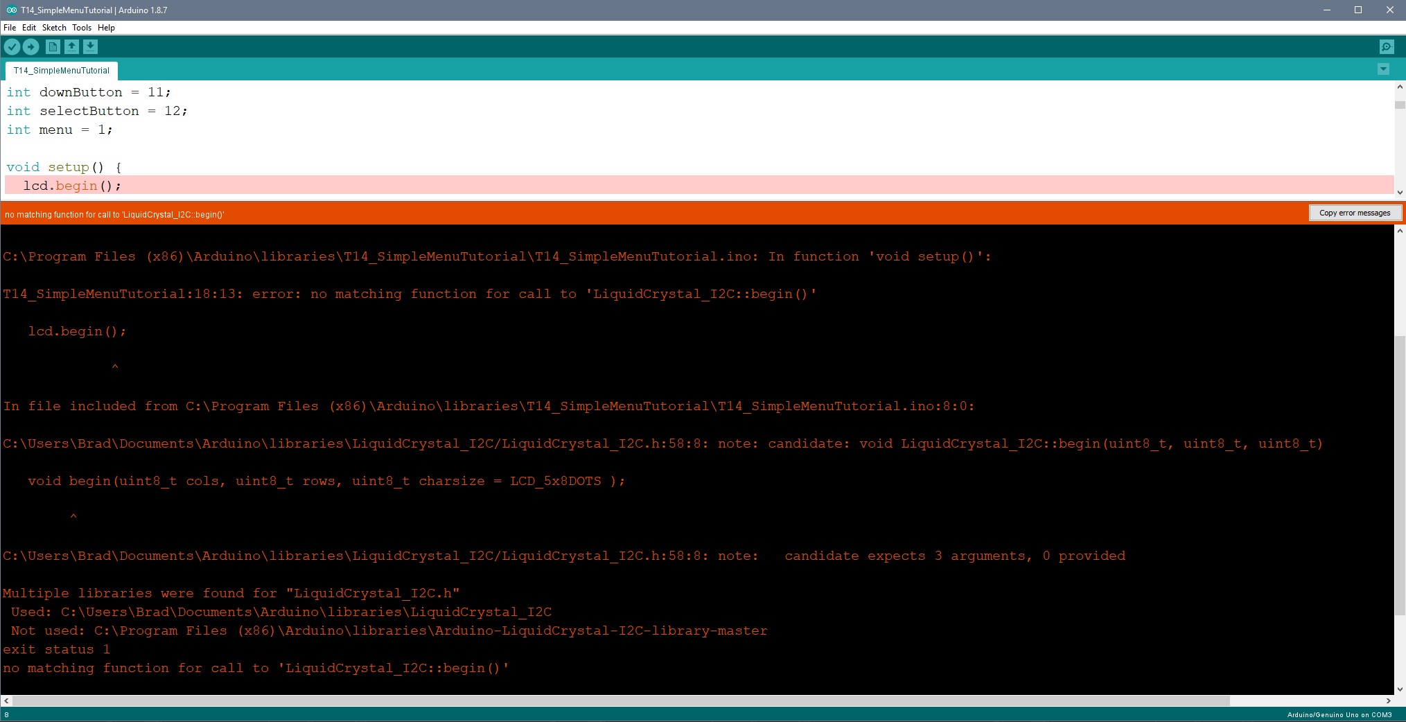
Can someone help me with this error....? I'm new to programming and have NO idea what this means... https://i.imgur.com/fcD52nM.jpg
 restive charm
@coarse smelt It's saying that It can't find a begin function that takes no arguments. It's telling you that it found a begin that takes three arguments
@coarse smelt Are you working from an example? From what you posted it looks like you have to call begin with arguments for the number of columns and rows with an optional arg for character size
coarse smelt
I'm working with this code.. https://github.com/MaxTechTV/Tutorial_Sketches/blob/master/T14_SimpleMenuTutorial/T14_SimpleMenuTutorial.ino

GitHub
Sample Sketches for Arduino Tutorials. Contribute to MaxTechTV/Tutorial_Sketches development by creating an account on GitHub.
restive charm
Did you install the LiquidCrystal_I2C library through the Arduino library manager?
coarse smelt
Yes I did
restive charm
Check File->Examples->LiquidCrystal_I2C to see if there are any examples that came with the library and try those first
coarse smelt
Yeah, nothing. Appreciate your help. I'll keep trying lol!
restive charm
@coarse smelt The issue is that there seems to be a mismatch between the functions that the version of LiquidCrystal_I2C you're using provides and the ones that the author of the code you're trying to use. You can try looking at the .h file for the library under your libraries directory, where the Arduino IDE installed it.
You'd be looking to see if the .h file (probably something like LiquidCrystal_I2C.h) has a function signature for a begin function that doesn't take any arguments or only has optional arguments
coarse smelt
It does reference this in the LiquidCrystal_I2C.h file
- Set the LCD display in the correct begin state, must be called before anything else is done.
*/
void begin();
restive charm
I just noticed that in the error you posted above it's complaining about finding two copies of the LiquidCrystal_I2C. You might compare the two
pulsar charm
Are there any significant benefits of programming bare metal chips like the ATTiny and the ATmega328 that I should be made aware of?
I haven't really tried it, but I'm not particularly compelled because I can't really think of any use cases, unless I've started custom making my own PCBs or really like handwiring, or looking for some cost or power savings
Did I nail these right?
north kelp
If you're building something very small, that can be handy.
pulsar charm
in what sense handy? So you're suggesting it could be great for wearables?
north stream
It can also be useful if you want every single byte of flash for your own use, if you want to use a different sort of setup (different clock, reset pin as I/O), or need full control for some reason.
 sturdy bobcat
Also, you don't need to have it one way.
I'm waiting for the PCB's on my new lightpainting board and I really want it to be a small, discrete, one-piece package with everything arranged to my needs.
It's also an Arduino/Wiring compliant board that I can use the Adruino IDE to program.
Similarly, you can use any of them in a bootloader-less mode with the ISP interface instead of the bootloader.
north stream
I'm also fond of making custom boards that work with the Arduino IDE
sturdy bobcat
Yah, note the 6 pin connector on the corner for the FTDI cable.
north stream
Also the ISP connector on the left for direct programming.
 stark bridge
Late answer, but the reason I like programming for bare metal is that you don't run into issues of conflicting libraries like you do with Arduino. For example, sometimes two Arduino libraries will try to use the same timer or same interrupt and so they don't work well together. When you program for bare metal you control all the resources so you can make sure they don't conflict. But it's a LOT more work than writing Arduino code. Another reason is that non-Arduino chips sometimes have special features you can't get on Arduino like the ability to use any pin for any purpose (no special analog pins, PWM pins, etc.)
thorn sand
hey i got these on my epaper what is wrong? is my screen dead?
north stream
The LED one has a few issues. There's an if that does nothing, then one that checks a pin and then sets two pins. I'm unsure what the intent is.
Those epaper pixels look digital. The random ones seem real. The line might be a bad connection.
 celest sable
yea im trying to make a switch by using a button (but the leds need to be so that if i press the button the green turns on and the red turns off and same way if i press it again but the leds turned arround)
restive charm
@pulsar charm The requirements of your project will tell you if programming "bare metal" chips as you say is worth it. I don't know exactly what you mean by that term, but I can assume you're contrasting it with either a> using pre-made development boards like Feathers or Arduinos, or b>programming the chips using an existing framework like Arduino, Mbed, CMSIS or something similar.
In either case for smaller, low volume projects you're almost certainly not going to save any time or money spinning up something custom; hardware or software. In either case you would be trading flexibility for money and time. Custom hardware is easier to justify than writing a dev framework from scratch because you're more likely to have requirements that would impact the hardware design than the underlying programming framework.
I design custom boards as a hobby because I enjoy the process, not because I couldn't do the same thing cheaper with existing products.
north stream
Ah, you want a toggling functionality.
Perhaps something like: ```c
static bool state;
if (digitalRead(BUTTON_PIN)) {
digitalWrite(LED1_PIN, state);
state = !state;
digitalWrite(LED2_PIN, state);
delay(100);
}
Thanks @north stream , @restive charm and @sturdy bobcat for the input. Right now I'm mostly programming with arduino/esp and I've been tackling my learning path based on a use-case basis. I don't know if its ignorance or by design that my problems never required the use of these standalone avr programming chips (term corrected here, as I might have misunderstood 'bare metal' ie like arch-linux's "bare-metal"). It just seemed convenient to have all batteries included considering the carrier board product ranges is well diversified so it was a matter to me of "choosing the right board". I was actually wondering if this will become a legacy thing, with more tiny form factor boards popping up.
I think I might have to really read up on the interactions between the dev frameworks and boards to really grok this. As of right now, library conflict is never an issue for me because I pretty much rewrite libraries from scratch (my idea of full control). But yes, I'm getting a good idea that this might be a deep dive and that's where the fun begins!
north stream
If you're already rewriting most libraries, then the environment is basically functioning as a development environment, and there are several choices for those too. Once you've decided you want full control, it's not much of a deeper dive to just take over and run the CPU however you like. There are some real advantages to the "I own the universe" style of programming.
restive charm
@pulsar charm People use the older avrs, pics, and whatever other chips by themselves and not on a dev board because a> that used to be the only choice to do it cheaply, b> historical preference c>liking the idea of bootstrapping d>whatever reasons. I think it's safe to say that "Arduino", the concept not the specific board, is today's PIC/AVR. It's a perfect place to start.
I started in that realm and while I'm happy to have started there and learned, honestly things are much better now; the tools are better, the chips are better, the libraries and dev environments are better. People still bend over backwards to make Commodore 64s do amazing things, but that doesn't mean they're a the best investment of your time.
Once you get to the stage of pouring over the datasheet for MCUs or other chips like some kids do car magazines, there is a good chance you'll outpace the learning resources and tools that are available. When I first read the feature summary in the SAMD51 datasheet nearly every bullet point was like "wow, that too?!". However, you can't just find an example laying around of how to use all the features together, or even individually, at least not in a way that's as easy as loading an example in the arduino IDE. Eventually, there will be a feature of the chip that I will have to figure out how to make it work on my own by reading the relevant sections of the datasheet over, and over.
A way to get a sense for the above is by finding a sensor or other non-mcu chip that is interesting to you, reading the datasheet, and then writing a driver. To start, you can even take something that already has a breakout and driver available, using the existing driver as a reference to write yours. There is a very good chance that in comparing the datasheet to the existing driver you'll find features of the chip that haven't been exposed yet.
This can be a very rewarding hobby or even profession. Enjoy the journey!
pine bramble
Is there some way I can send an audio file to the arduino and analyze the data from it? I don’t wanna use a microphone.
barren scaffold
You have an audio file on a computer of some kind, and wouldn't want to analyze it there?
 leaden dew
Hey all, hope everyone's having a good day so far. I got a 128x64 OLED display and I'm trying to code it as an SPI rather than as a IIC; I messed up one of the connection ports. But I still don't understand how the constructor works (under the U8GLIB library); anyone got any experience?
 dusty grove
Hey everyone! I'm a bit of a noob with Arduino and would love advice/guidance regarding my project!
Essentially I ordered two 2.8" TFT LCD displays and I have an RFID sensor. What I'd like to is once the RFID sensor recognizes one type of tag...and has two different images to each LCD screen. So image A would appear on LCD display A and image B would display on LCD display B.
What I realize I got stuck with is just how many pins this would require and am feeling a bit confused on how to proceed! Any ideas?
inland crag
are they spi? you could share mosi/sck and have a chip select that determines which one is active
dusty grove
uhhh
omg sorry
yes i think it is!
SPI
Also not sure if I understand by what you mean by chip select
I think i also forgot to mention that ideally i'd like 2 images simultaneously projecting
onto the different LCD screens 😮
__< Sorry
inland crag
yeah that should be doable.
you only need like 5 gpio if you don't need touch or backlight control
dusty grove
@inland crag - would you mind if i move this conversation to DM so I don't dilute the chat w/ my dumb q's haha?
inland crag
sure
burnt island
assuming the buttons are each connected to a pin and ground, yes
pine bramble
pinMode(But1, INPUT_PULLUP);
pinMode(But2, INPUT_PULLUP);
pinMode(But3, INPUT_PULLUP);
pinMode(But4, INPUT_PULLUP);
pinMode(But5, INPUT_PULLUP);
pinMode(But6, INPUT_PULLUP);
pinMode(But7, INPUT_PULLUP);
i wasn't sure if positive or negative edge triggered
thank you
 tight badge
Are there any example sketches in Arduino that will control a neopixel strip with the circuit playground express through the Adafruit Bluefruit app?
dusty grove
Does anyone mind helping me with hooking up my LCD display? >__< Sorry I'm really confused about the pins between the different models that the tutorials have and the specific version of screen that I have. Ideally, I'd like to be able to have one arduino mega have two different outputs for each of the screens (image A goes to LCD screen A etc). Therefore I'd like to connect the LCD's not via shield connection but by just wi..ring?
I think I'm getting confused between a "shield"and not...as well just the general pin setup!
barren scaffold
(11 hours later) Having no idea about the LCD hardware, https://learn.adafruit.com/adafruit-2-dot-8-color-tft-touchscreen-breakout-v2 is a writeup for a non-shield version of an LCD that includes some convenience libraries from Adafruit. Page 1 says you can use as few as 5 pins for the LCD as long as you're ok with the slower display rates. (And now I see other conversations in #help-with-projects that may supersede all of this.)

Color! Lights! Touch! 8-Bit! SPI! MicroSD Card! Pickles!
dusty grove
@dark wigeon - thank you for still posting 😃 I really appreciate it!
 granite belfry
hi there,
I got a problem with me system
my lcd screen is garbled when it switched a relays so i think i can fix this wit a capacitor need i place this on the + and ground on the relays board or on the - and in1 (signal cable)
north stream
You may also want a diode to absorb the inductive spikes that relay coils can create when switching.
pine bramble
Is anyone familiar with DAC signal generation?
 tawny parcel
I'm having issues getting this Bluefruit LE UART Friend to connect to the bluefruit app to send data to a phone via bluetooth. Anyone have time to take a stab at helping?
I'm using an ItsyBitsy M0 Express as the main board and I have a BN0O55 Absolute Orientation Sensor to get orientation data that will eventually be sent over bluetooth to display on a phone. I just cant for the life of me figure out how to get the data pushed over bluetooth. I'm VERY new at all of this, don't really even know the code to be honest. Just hacking away at it.
 tidal peak
I don't understand why my arduino .ino file can't find the .h file I have, even though I have them in the same sketch folder
north stream
It ought to be able to, there are several reasons it may not be working. First, try restarting the IDE to re-scan the directory. If the IDE sees it, it should show up in a separate tab.
By way of illustration...
tidal peak
that didn't seem to work :/
north kelp
@tidal peak Does your .ino file have #include "myothercode.h" near the top?
@tawny parcel Have you worked through the primary guide for the Bluefruit UART Friend, step by step?
https://learn.adafruit.com/introducing-the-adafruit-bluefruit-le-uart-friend/

Your BLE UART BFF!
tidal peak
I found a way to make it work, thx though!
north kelp
What was the solution?
tidal peak
opened it in notepad++ and resaved it as the source file
 charred mango
I am trying to control a TV with an IR diode but I do not have the original remote and cannot find the IR hex codes online. Anyone have any ideas on how I could find the IR patterns?
sinful saffron
find like remote codes (same manufacturer), replacement remote lol? Maybe see if someone has them or can get them on reddit or something
charred mango
hmm do you know if its possible to use the base 10 remote codes taht you typically use to program a remote and convert those into the hex codes?
sinful saffron
sadly don't, would have to research what the standards are and if they could be converted
what brand is the remote?
actually, what's the device
charred mango
its a westinghouse
I may have found something.
I think I may be able to use these codes
sinful saffron
might be able to pull the codes from a universal remote such as Logitech if you have one (and an IR receiver)
north kelp

Use an ordinary TV remote to control your next project
sinful saffron
they have a site to see what devices are "compatible" out of the box
charred mango
@sinful saffron Ok ill try to match those
north kelp
charred mango
@north kelp yeah all that makes sense. I just need to find the correct codes
north stream
Check out http://www.lirc.org/ for a huge library of remote codes
wintry berry
hi
how do I divide an addressable ws2812b led strip to 2, and jump the color of each
section with a button
so 1 led strip, 2 push buttons, 2 color sections
north stream
If I understand correctly what you want (only update a section when its pushbutton is pressed), connect the + leads together, and the - leads together. For each data in connection, run a 10kΩ resistor from it to -, and connect it to a pushbutton. Connect the other ends of both pushbuttons together, and to the microcontroller pin doing the updates. Note that if you push both buttons at once and have the microcontroller send an update, it will simply update both strips, nothing will be harmed.
mild elk
I want to measure current with my arduino using 0.01 ohm shunt resistor, but 10bit ADC resolution is not enough for an accurate reading. Can I use an op-amp to amplify voltage across my shunt and then feed it to the arduino? Or should I rather just use a higher resolution external ADC?
 sonic rock
Can the arduino be used as a oscilloscope? (Analog inputs)
stark bridge
In theory it could but I'd probably want to use a faster processor for any real oscilloscope applications.
barren scaffold
https://arduino.stackexchange.com/questions/699/how-do-i-know-the-sampling-frequency confirms. Not for anything of any real frequency.

Arduino Stack Exchange
I am beginning to get a bit confused about sampling rates and baudrates etc. I have this Arduino code:
#include <eHealth.h>
extern volatile unsigned long timer0_overflow_count;
float fanal...
north stream
Measuring small currents with low-value resistors is tricky. Op-amp circuits can help (that's how the µCurrent works), there are also dedicated chips designed for the purpose (some include the sense resistor as well). In general, boosting the signal will give better results than a higher resolution digitizer. If your load can tolerate a little voltage variation, you can use a larger sense resistor. The fancy way is to use a Kelvin connection so the power supply regulates the voltage on the load side of the sense resistor, then you can use a larger resistor without affecting your supply voltage.
 proper forum
the diodes from RESET_5V to RESET and RXD_5V to RXD are to allow the 3.3v ESP32 to communicate with 5v signals correct?
Would it require the 3.3v side to be pulled high
 bleak glacier
@wintry berry Start with the neopixel uberguide https://learn.adafruit.com/adafruit-neopixel-uberguide/the-magic-of-neopixels and then the 3-parter multitasking arduino https://learn.adafruit.com/adafruit-neopixel-uberguide/the-magic-of-neopixels If you have a strip of say 60 neopixels, you can code color changes for pixels 0-29 and a different color change for pixels 30-59 to split the strip in two or run an animation through the entire strip. Because of the way the arduino runs and senses switch presses, you'll use the technique outlined in that multi-tasking tutorial. @north stream Doing that hardswitching of the data input to neopixels might be iffy. I've fried a couple of neopixels just by reattaching the data wires when powered up. The loss of data/initialization of neopixels seems to put them into a random state or color/on/off so they are pretty sensitive.

Adafruit Learning System
Everything you always wanted to know about Adafruit NeoPixels but were afraid to ask

Adafruit Learning System
Make your Arduino walk and chew gum at the same time.
 sonic relic
yo does anyone know of a library similar to fastLED that will work with nonrgb/addressable leds?
bleak glacier
@sonic relic nonrgb meaning RGBW?
sonic relic
like just a single color led
bleak glacier
so the question is that they are still addressable?
sonic relic
its for a led cube that is just using basic non addressable single color leds
bleak glacier
Hmmm, the question gets deeper with what are you trying to do, run animations and how big a matrix of leds you have, that is done using different programming and hardwiring different from fastLED.
or neopixels/dotstars which are addressable leds
sonic relic
its a 4x4x4, common anodes on the columns and common cathodes on the rows and just trying to do simple animations
bleak glacier
I don't see any tutorials on the basic LED cube in Adafruit right now but check on instructables, sparkfun, hackaday,... there should be a lot of examples out there to wire up a 4x4x4 and code. With your basic LED you can turn them on/off and maybe get the brightness level controlled.
sonic relic
cool will do thanks for the help :)
bleak glacier
Depending on the board you are using, there is a limit of how big your cube can go because you run out of pins to use which control the voltage going to a "charlieplexed/multixplexed" cube. Good luck.
bleak glacier
@proper forum I dunno but could be something similar with you have to do for other chips - like attiny85 with arduino, it kept it from auto-resetting when you tried to program it.
proper forum
interesting
RESET appears to be pulled high by the 10K resistor
and then is connected to GND by the 1uF cap
and the user can pull reset to low by pressing the button
this is connected to the cp2104
@bleak glacier so you're saying it's probably there to prevent accidental resets?
bleak glacier
@proper forum Haha, I really don't know what I am saying. When I programmed attiny85 chips, it needed a capacitor on the reset. If you look up arduino, it might have something to do with what the IDE was talking to the bootloader or the code memory.
north stream
I don't see a pullup or pulldown on either, but I assume they're elsewhere.
Q2 will pull GPIO0 low if DTR is low and RTS is high.
proper forum
blue circle is connected to the reset pin
as far as I can tell
I believe the Q1 and Q2 part is part of the auto reset feature
north stream
Yeah, all the nodes labeled "RESET" are connected together, so the capacitor, switch, pullup resistor, and (presumably) the reset pin are all tied together. The capacitor is to yield a power-on reset. Sometimes there's another, smaller capacitor tied to a signal an external computer can drive.
In this case, instead of a capacitor, it appears that DTR and RTS (from the USB-serial adapter chip?) are used in combination to drive GPIO0 and RESET as well.
proper forum
so it keeps the voltage that the reset pin sees more stable
which prevents a power on reset
makes sense
north stream
I've always been a little leery of the capacitor-coupled reset circuit, as it makes both positive and negative spikes, which have to flow through the chip's protection diodes.
 elfin oar
Has anyone tried the TinyUSB stack? I can get it to work, but I'm having trouble accessing the fatfs concurrently with msc. I'd settle for even disconnecting USB when accessing locally. SPI flash or SD card.
proper forum
if I increased the relay supply voltage to 5v, would the diode be potentially damaged by the increased voltage?
the LED's I'm looking at say reverse current Vr=5V of 10 uA
hm absolute maximum rating at 25c is 5V reverse voltage
that sounds yikes
unless the led would only be dealing with a reverse voltage of 1.7V
north stream
That is just a "relay on" LED, you could disconnect it (there's a jumper for that) if desired. If you wanted to keep its functionality, you could add a series protection diode (the easiest way would be to open that jumper and install a diode there).
mild elk
Hi! I have this weird probkem: I have a circuit that measures its supply voltage through voltage divider and measures current of LEDs. It measures voltage correctly when no current is measured, however when I load current measuring output my voltage reading increases. Any ideas why is that?
Also the voltage and current readings are quite unstable even though I take average of 10
north stream
A lot of that depends on how your circuit is designed. How is it measuring the current? Does the supply voltage sag when LEDs are lit? How is the digitizer reference voltage derived? Is there ground impedance? Separate supplies?
mild elk
Its measuring current with 0.05 ohm shunt resistor and op-amp with gain of 11. Supply voltage drops down to 4.7V, but it shows 5.2 on the display. I'm using onboard 10bit adc, didn't touch anything regards reference. Everything runs from single power source
north stream
That can be tricky. You might be able to rearrange things so the processor is powered directly and the LEDs via the shunt resistor, but that won't let you monitor the processor current draw (I don't know if that's important in your application). Many of these processors have a separate analog reference (AREF) input that is by default connected to the supply voltage (which can vary, affecting your digitizer results), but connecting it to a regulated supply of its own can help a lot.
mild elk
My processor is purposely connected before the shunt because I don't want to measure its power draw. In final application I will use it with buck-boost converter because my input voltage may rise well above 5V as well as drop below that. Using analog reference is an option on uno, but not on pro mini which I want to use. I'm building a USB meter and as You can imagine it's pretty tight in there.
north stream
I vaguely recall that on a Pro Mini, you can set the ADC to use a built-in internal reference, but you'll have to write the device registers directly to do so, and I think the internal reference is low voltage, so you'll have to adjust the input levels to match.
mild elk
Can't I just use analogRefererence(INTERNAL)?
 tired flume
Im thinking about of using arduinos instead of raspis?
are arduino's kind of like raspis
crystal mesa
The are essentially microcontrollers with some extra circuitry added on for hobbyist comfort
The biggest difference is that Pis runa full operating system. Arduinos do not.
north stream
RasPis are much more powerful (fast 32-bit CPUs with lots of memory), but paradoxically, if you need fast, real-time performance, Arduinos are often the better choice, because RasPis have that operating system borrowing CPU cycles unpredictably, whereas you can tell an Arduino to devote itself 100% to a particular piece of code if you want.
 ivory walrus
You could run an RTOS on a Pi, but that is more work.
sinful saffron
RasPis can do more intensive calculations and GUI, but Arduino has better IO and timing. Now if they could just combine the two lol
I'd use an Arduino if the project can be done with it though (very easy to setup and run)
ivory walrus
BeagleBone has PRUs
Iirc an arm + 2 PRUs for the Beagkebone black, it literally is pretty much exactly what you described.
north stream
I'll often do exactly that: combine the two. I'm fond of using Firmata to send commands and data back and forth. You'll see a lot of CNC machining setups that work the same way, they'll use a dedicated sub-processor to do the timing critical bits, and a separate computer to do the command and control, UI, etc.
 lime gulch
Ok I need help. I am trying to get a thermistor working on a feather huzzah using the ADC pin. The project successfully worked on an Arduino Uno but when I move it over to Feather Huzzah ADC it give me a static reading. I have not changed anything on the breadboard. U used this website for reference.
The question is, why would it not be working on the ADC for the Huzzah? What am I missing?
Arduino code is the same.
Learn how to use an analog thermistor to measure temperature on the Arduino. Output readings to an LCD or the serial monitor in Celsius or Fahrenheit.
That is the website
Also, I am using -- analogRead(A0);
north stream
Are you using WiFi?
lime gulch
Not yet. I am just printing to serial now
north stream
Hmm, I know the ESP doesn't support certain ADC pins when WiFi is enabled.
lime gulch
Ok let me make sure
north stream
Some information here (along with some confusing details on ADC channels/multiplexors) https://desire.giesecke.tk/index.php/2018/01/30/adc2-channel-cannot-be-used-when-wifi-is-in-use/
lime gulch
Thank you . I will check this out
lime gulch
@north stream That did not work. I will try another sensor in the morning. Thank you for the help.
north stream
Weird that it works on Arduino but not Huzzah.
lime gulch
Yep. Eliminated everything WiFi and just put down a simple script to read from PIN 2 (analogRead(A0);) and it still did not work. It just read Absolute Zero -459.67
I even tried another Dev board
north stream
Tried any other analog pins?
bleak glacier
@lime gulch Big thing to watch out for is your sensors that are 5v logic level for a regular arduino, could be/need 3.3v for Huzzah? The calculations would be off and the paired resistor for hookup might not give it analog voltage readings in the range you expect. Good luck.
@pine bramble You had a question?
pine bramble
Hello guys. I have a lot of free time so I was thinking what to do. I was wanting to buy a steering wheel for my PS4, but thought “why not make one myself?” By using tilt sensors for x movements and build the buttons inside a steering wheel. How difficult could this be for a beginner and is this a realistic project?
I didn’t want to make something off internet, like an automatic opening garbage bin.
Accelerometer not tilt sensor
north stream
A lot of steering wheel controllers use a variable resistor to read off the angle of the wheel directly, but it can be done with a accelerometer (like a Wii wheel). What I don't know is how difficult it is to talk to a PS4.
sinful saffron
for a beginner project I would probably pick up a used steering wheel and feed values into the existing pot connections (unless you can find that someone else has already adapted to the interface and is working).
tired flume
Can i like ssh into an arduino and have like a filesystem?
or can i only do that with pi
 past wave
@tired flume pretty much pi only.
You can connect your arduino to a pi (that you SSH into) to do things with the arduino though
But a raw arduino by itself can't reasonably have something similar to a filesystem. You can use it to write data to memory devices though.
sinful saffron
Arduino Yun is pretty cool, can upload sketches remotely and interact via a web server
pine bramble
Yun
 errant geode
Hey. It is possible to connect Arduino with sd card to computer with Windows and browse sd card wia USB, like normal pendrive or something?
pine bramble
@burnt yew
odd fjord
@pine bramble That looks like a PIR https://www.adafruit.com/product/189

PIR sensors are used to detect motion from pets/humanoids from about 20 feet away (possibly works on zombies, not guaranteed). This one has an adjustable delay before firing (approx 2-4 ...
odd fjord
it detects motion of "warm bodies (sensses infrared)" so it is a good motion sesnor. I use one to turn on my desk light when I enter my office.
lots of information here: https://learn.adafruit.com/pir-passive-infrared-proximity-motion-sensor
 pine bramble
@odd fjord with arduino?
I was planning to make a obstacle avoider robot
So what can i make with pirr
odd fjord
This wont be good for that since it won't sense things like wals. The ultra sonic sensor would be much better
odd fjord
It is best used to detect when a person or animal crosses in front of it. Good for secuity cameras or automatic switches
the prices vary -- there are several types of untrasoninc -- here are a few https://www.adafruit.com/product/4007 https://www.adafruit.com/product/4019 these cost less tthan the PIR from Adafruit, but I have seen both for less on other sites,

If you're like me, you've dreamed of being a dolphin - smoothly gliding through the water. Using your echo-location abilities to detect tasty fish treats. Until genetic modifications ...
If you're like me, you've dreamed of being a dolphin - smoothly gliding through the water. Using your echo-location abilities to detect tasty fish treats. Until genetic modifications ...
I tried some very inexpesive ultrasonic sesnors but they did not work very well...
I have used the HC-SR04 for robot obstacle avoidence and it works well. The US-100 can be used the same way but has more options. I have not tries it yet. I have alos used these https://www.adafruit.com/product/3025

If you're like me, you've always wanted a smaller and faster way to sense an object between 0.5 and 5 centimeters away. If you're really like me, you've wanted the ...
here is an example: https://learn.adafruit.com/adabox002/make-your-robot-autonomous
 pine bramble
Using arduino.
odd fjord
You can use Arduino with all those sensors.
north stream
@errant geode Huh, someone else asked essentially the same question yesterday. Basically, no, the Arduino does not have the horsepower to emulate a USB drive.
 viral creek
Hi all, Any help on this would be much appreciated. I am needing to add several serial communicating sensors to a system that currently has an Feather M0 Adalogger as the microcontroller. From what I can tell the adalogger has one HW serial for the usb and one spare as standard, apparently any pin can be used for this though I am not sure how this would be done. I am testing currently with an Arduino Mega which has 4x HW serial ports and would like to know if this is transferrable to the adalogger, else I have found something like the teensy 3.5 which boasts 6 HW serials and is compact and quick. Cheers
https://www.adafruit.com/product/2796

Feather is the new development board from Adafruit, and like its namesake it is thin, light, and lets you fly! We designed Feather to be a new standard for portable microcontroller ...
barren scaffold
Does this get you enough serial ports? https://learn.adafruit.com/using-atsamd21-sercom-to-add-more-spi-i2c-serial-ports (found on the Adalogger page, assuming it's directly applicable)

Adafruit Learning System
Get more high speed serial commports without bitbanging
 fallow harbor
Could someone possibly help me to adapt this code with the u8glib library for an OLED? https://create.arduino.cc/editor/Electorials/c4bebb92-959a-410d-ab85-d4d419f9457f/preview
Arduino Create simplifies building a project as a whole, without having to switch between different tools to manage all the aspects of whatever you're making.


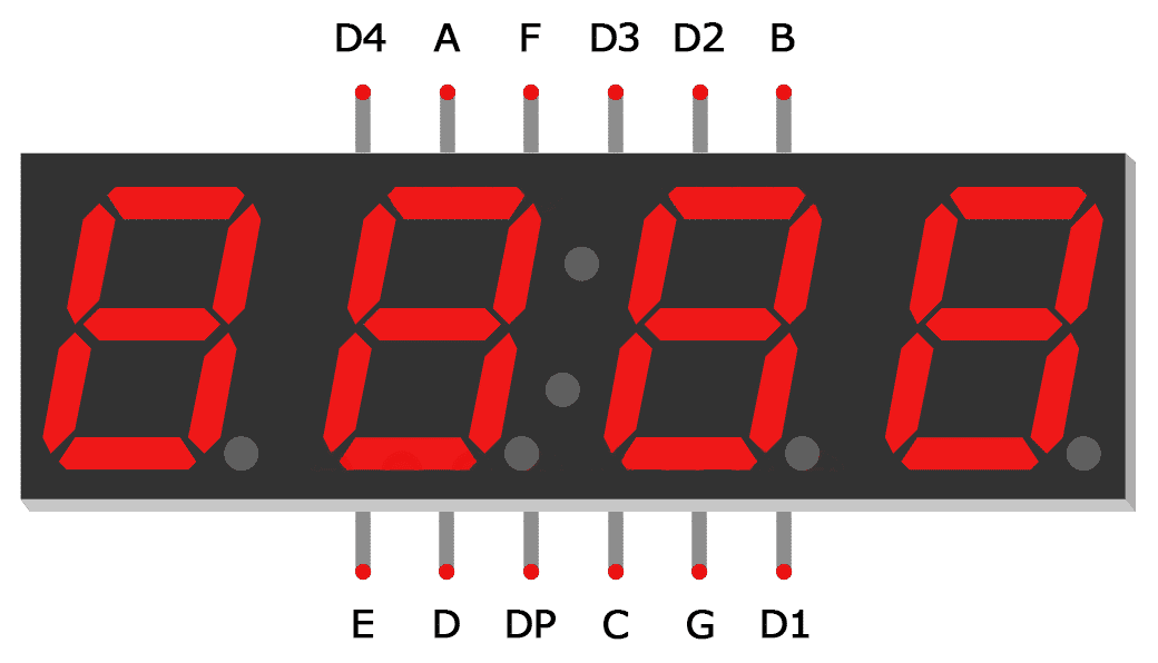

 fallow harbor
Yes, the code I posted is adapted for a LCD display.
I tried to adapt it but it didn't work, I'm more used to using the Adafruit ssd1306 library.
pulsar charm
ah I see, I haven't done it either but I've got a project that requires me to refactor it to u8glib too
Doesn't look too complicated imo, so you just need a sample example?
fallow harbor
I guess that would be fine.
pulsar charm

Getting Started The assumption here is that you’ve already downloaded the U8glib library and have properly installed it into your Arduino folder. If you haven’t, you can get the downlo…
Henry's bench did a simple one, is your oled spi or i2c
fallow harbor
I think I know what I did wrong all this time now, let me get to work quickly.
pulsar charm
Yeah watch your declaration
there's an i2c example if you need one: https://eecs.blog/arduino-i2c-oled-screen-tutorial-using-u8glib/
@fallow harbor good to hear!
 undone oracle
Hey im working on a solar tracking project using arduino. I would appreciate if someone can go over my code with me. I will post it in a pastepin so you can look at it. I just need to clear a few thing up. Thanks for the help!
mild elk
I wanted to parse a Json downloaded from internet on ESP 8266 and output data I need over serial, but I can't quite get it to work. I got it to download json and send it over serial, but it's so big that I can't parse it on atmega328, and it's a string while ArduinoJson expects a char
 woven mica
You can convert Arduino String to a pointer to char array using string.c_str()
How big is the JSON?
mild elk
REALLY big
It's parsing program generated on assistant website is over 300 lines long
I trimmed it down a bit though
woven mica
You could parse it on the ESP
woven mica
How much data do you need from it?
woven mica
That is still a lot, you should parse it on ESP
mild elk
Agin, that's what I'm trying to do
woven mica
ok
mild elk
My problem is mainly due to ArduinoJson expecting a char, while HTTPS GET request returns string
woven mica
You can convert the string to char array
 half glacier
Hi guys, I'm a complete newbie to Arduino but I need to get a simple circuit together with two servos that turn to a specifies angle simultaneously via a button and then back again when pressed a second time. I'm not sure how it all works and I can't find information that Narrows it down for me. Any help is appreciated as its for a heads up display mounting backed inside a power armor suit :) thanks
woven mica
What does the error say @mild elk ?
@half glacier look at the Arduino examples at their website, there are schematics for connecting buttons and servos to Arduino https://www.arduino.cc/en/Tutorial/Sweep https://www.arduino.cc/en/Tutorial/Button
half glacier
Will do, thank you @woven mica
mild elk
In file included from /home/pi/Documents/Arduino/libraries/ArduinoJson/src/ArduinoJson/Operators/VariantOperators.hpp:7:0,
                 from /home/pi/Documents/Arduino/libraries/ArduinoJson/src/ArduinoJson/Variant/VariantRef.hpp:12,
                 from /home/pi/Documents/Arduino/libraries/ArduinoJson/src/ArduinoJson/Array/ArrayIterator.hpp:8,
                 from /home/pi/Documents/Arduino/libraries/ArduinoJson/src/ArduinoJson/Array/ArrayRef.hpp:9,
                 from /home/pi/Documents/Arduino/libraries/ArduinoJson/src/ArduinoJson.hpp:17,
                 from /home/pi/Documents/Arduino/libraries/ArduinoJson/src/ArduinoJson.h:9,
                 from /home/pi/Documents/Arduino/test_json_esp8266_parse_in_place/test_json_esp8266_parse_in_place.ino:3:
/home/pi/Documents/Arduino/libraries/ArduinoJson/src/ArduinoJson/Operators/VariantCasts.hpp: In instantiation of 'ArduinoJson6111_00000::VariantCasts<TImpl>::operator T() const [with T = char*; TImpl = ArduinoJson6111_00000::MemberProxy<const ArduinoJson6111_00000::ObjectRef&, const char*>]':
/home/pi/Documents/Arduino/test_json_esp8266_parse_in_place/test_json_esp8266_parse_in_place.ino:63:54:   required from here
/home/pi/Documents/Arduino/libraries/ArduinoJson/src/ArduinoJson/Operators/VariantCasts.hpp:16:35: error: invalid conversion from 'ArduinoJson6111_00000::VariantAs<char*>::type {aka const char*}' to 'char*' [-fpermissive]
     return impl()->template as<T>();
                                   ^
/home/pi/Documents/Arduino/libraries/ArduinoJson/src/ArduinoJson/Operators/VariantCasts.hpp: In instantiation of 'ArduinoJson6111_00000::VariantCasts<TImpl>::operator T() const [with T = char*; TImpl = ArduinoJson6111_00000::MemberProxy<const ArduinoJson6111_00000::MemberProxy<const ArduinoJson6111_00000::ObjectRef&, const char*>&, const char*>]':
/home/pi/Documents/Arduino/test_json_esp8266_parse_in_place/test_json_esp8266_parse_in_place.ino:65:61:   required from here
/home/pi/Documents/Arduino/libraries/ArduinoJson/src/ArduinoJson/Operators/VariantCasts.hpp:16:35: error: invalid conversion from 'ArduinoJson6111_00000::VariantAs<char*>::type {aka const char*}' to 'char*' [-fpermissive]
In file included from /home/pi/Documents/Arduino/libraries/ArduinoJson/```