#help-with-arduino
1 messages · Page 34 of 1
 celest finch
@swift fable Sorry, which suggestion?
 swift fable
@Fireflash can you try to run your analog wire along with gnd tied togother?
swift fable
@celest finch this one
 fierce ridge
Hello everyone, im looking to reset my MKR1010 which runs a script to check for an active wifi connection by pinging google. If it fails after N attempts, I want to reset the script and clear all the registers (I have an LED that turns on if the failed pings > 1).
I tried jumping Pin 14 to Reset and setting it high but that didint reset. I then tried
void(* resetFunc) (void) = 0; //declare reset function @ address 0
Which I thought was declaring a function to reset the arduino and I would call it in my for loop that checks failed pings via
resetFunc(); //call reset
but that also didint reset the script :/
Any ideas what im doing wrong?
fierce ridge
@swift fable is that a built in function or do I need to declare it?
fierce ridge
Thanks!
celest finch
Alrighty, gimme a few.
 upper rune
@swift fable adding File myfile; didint fix the problem
swift fable
@upper rune and did u try removing the
using namespace SDLib;
in sd.h
upper rune
if i do that i get this error @swift fable https://pastebin.com/eQ4LiY8R

Pastebin
 ancient mica
Hey all. I'm writing up some code for a Feather M0 Bluefeuit with a mini tft joystick wing. Is there a better way to watch for multiple buttons than checking each in a loop in Arduino?
The idea is to use it to control another device via Bluetooth using the BLE keyboard capability of the Bluefruit by sending keys, and I want to have it be as efficient and quick as possible.
 leaden dew
i'm trying to edit the colourview example in the TSC34725 example library to output the values to a display rather than to serial. I managed to do some of the things i want to do but i keep getting the error; expected constructor... before '(' token
 barren scaffold
@ancient mica probably as good as it gets as a concept. They're all separate digital IO pins, right?
 burnt island
@ancient mica looping on the M0 (or even the old atmega328) is way faster than bluetooth communication, so don't worry about that being a bottleneck.
barren scaffold
@leaden dew without a line number and code, nobody can say. But you've basically got a syntax error around that line, maybe as simple as a missing ;.
burnt island
it looks like the adafruit mini tft joystick wing is Seesaw based, so you can use digitalReadBulk to read all of the buttons at once
ancient mica
@barren scaffold they're the buttons in the tft mini wing, going through i2c (seesaw).
@burnt island thanks
Going to be fooling with the debounce tutorial later today for it.
 dire barn
hi everyone im having trouble using the trinket MO, i don't see the "Trinket MO" board in the SAMD list. Can someone please help me??
leaden dew
isn't the trinket similar to another board?
I think if you select that other board it would work
 native kelp
got a question: can a some sort of an arduino handle controlling like a 100W motor?
barren scaffold
@leaden dew given no line numbers from your original message, I'm going to guess that the error is on line 5. Don't think you can have multi-line #define statements.
@native kelp nobody directly controls higher-power motors directly through a microcontroller. You'll want some kind of motor driver board. Something like https://www.adafruit.com/product/1438

The original Adafruit Motorshield kit is one of our most beloved kits, which is why we decided to make something even better. We have upgraded the shield kit to make the bestest, easiest way ...
barren scaffold
Same basic idea as https://www.adafruit.com/product/2935 -- let the microcontroller provide a low-power control signal, and let some beefier piece of electronics handle the full power required.

Say goodbye to hazardous high voltage wiring and create the Internet of Things with safe, reliable power control. The IoT Power Relay from Digital Loggers is custom designed ...
dire barn
@crystal mesa hi Devin, Yes I did. Can I uplaod a screen shot here?
can someone please help me with this error?
leaden dew
@barren scaffold heya, sorry no the error is on line 41, I tried compiling the code and it just kept saying the, constructor expected
barren scaffold
@leaden dew are lines 30- 66 in that code outside both setup() and loop()? If so, I don't think that's allowed.
leaden dew
ah
moved the } to just before the loop() and it compiled
thank you 😃 now all i have to work on is trying to get the values to print ahah
 solar sail
@dire barn Did you paste a block of code in the middle of the sketch template? That's definitely gonna give you problems.
dire barn
@solar sail I've never done this before. How am I supposed to copy it? I am still getting the error. Also do you know if there is a board for the Trinket MO? I only see Arduino MO.
 wraith current
@dire barn you also need to install the Adafruit SAMD boards https://learn.adafruit.com/adafruit-trinket-m0-circuitpython-arduino/using-with-arduino-ide

CircuitPython or Arduino IDE on this tiny little microcontroller board
@dire barn for your code error, you should put the #include line at the very top. (ie. NOT inside setup nor loop)
 crystal mesa
@dire barn for the first screen shot, does the Board Manager say that there is an update for your board?
dire barn
@wraith current yes i got that part installed thank you!!
@crystal mesa the error message says could not find board?
can someone please help? it
it
*it's my first time using arduino ever and i am really just trying to get the basic forward/backward motion to work.
barren scaffold
Most people start with "upload a program to make the Arduino LED blink on and off".
dire barn
@barren scaffold do you have a link for that tutorial please? trying to find someone that shows clear step by step 😦
barren scaffold

Learn Arduino! Lesson 1. Blink
crystal mesa
@dire barn So there is a generic Arduino SMD boards collection and then there is the Adafruit-specific one. Let me show you some screenshots.
Arduino ADE with two SAMD board packages present
So here is my Board Manager, and I've filtered on SAMD. I have four entries. The top one is the default Arduino SAMD boards collection, and from the screenshots you have shared that's the collection you have loaded.
The links that others and I have given you are how you install the entry I circled in blue, which is Adafruit's specific collection. Until you add that, you won't see the Trinket M0 show up in your board list.
And until you have that, you won't be able to upload any sketch -- default blinky or custom -- to your board.
There are three parts to getting the board support properly installed:
- Update the Board Manager with the correct custom URL so it knows how to find the board collections from Adafruit
- Select and install the Adafruit SAMD Boards collection
- If you're on Windows, install the proper driver bundle. Your screenshot looks like you're on a Mac, so I don't know if you need this step.
Step 1 you find the directions to here: https://learn.adafruit.com/adafruit-trinket-m0-circuitpython-arduino/arduino-ide-setup
CircuitPython or Arduino IDE on this tiny little microcontroller board
If you don't have this showing in your preferences, then Board Manager won't be able to find the package with your Trinket M0:
https://learn.adafruit.com/assets/33278
For step 2, you installed the Arduino SAMD boards already, but now you have to go back and install the Adafruit SAMD:, which is the step labelled "Install Adafruit SAMD" on this page: https://learn.adafruit.com/adafruit-trinket-m0-circuitpython-arduino/using-with-arduino-ide
CircuitPython or Arduino IDE on this tiny little microcontroller board
Once you've done that, they say (and I concur) to close the Arduino IDE and restart it. I've had board updates show up without it, but I've also had some weirdness, so it's easiest to close and restart.
That last page I linked to has the Windows drivers -- there is nothing there for Mac, so it looks like you can skip that step.
Finally, at the bottom of the page, under the heading called "Blink", it shows you how to load and upload the Blink sketch that someone previously mentioned. When you can do that successfully, you have all of the basic pieces in place to successfully communicate between your Mac and the Trinket M0.
So, you've done all that, and you still can't get the Arduino IDE to detect the Trinket? At that point, the first step is to check your USB cable and make sure you're using one that isn't a "charge-only" cable. You need one that is full data + charge.
 north stream
You may want to look at your USB bus and see if it shows up there (Click on the Apple logo -> About This Mac, then click on "System Report...", then click on "USB" in the left hand column.
 coral geyser
is it possible to read the orientation interrupt flag directly from the adxl346?
coral geyser
and is it possible to call an interrupt handler function like a normal function from within the main loop for example or not?
ok, never mind the second question, i just forgot about one safeguard i had in my code disabling the critcal parts for 1750 handler calls...
leaden dew
trying to fix this problem but I'm having no luck, any help?
leaden dew
wait don't worry, I forgot to add something at the beginning
dire barn
@crystal mesa Thank you!!!
north stream
That int display(); declaration should probably be either in a header file somewhere, or at least outside of setup().
leaden dew
anyone had fun with displays yet? (using the ssd1306 library) how do you stop the text from wrapping and starting another line?
 raw fiber
enum Page {
    PAGE_MAIN,
    PAGE_GRAPH,
    PAGE_BME
};

void drawPage(Page page) {
    for (int i = 0; i < 14; i++)
        buttonActions[i] = NULL;

    switch (page)
    {
    case PAGE_MAIN:
        buttonActions[0] = []() {
            Serial.println("My name a jeff");
        };
        break;
    case PAGE_GRAPH:
        break;
    case PAGE_BME:
        break;
    default:
        break;
    }
}
error: 'Page' was not declared in this scope
I dont know what is wrong here
north stream
I think you need ```c
void drawPage(enum Page page) {
When I'm programming in C, I'll use typedef to clean up such things, but typedef collides with C++ in "interesting" ways.
raw fiber
error: use of enum 'Page' without previous declaration
Interesting because afakik in "normal" c++ that should work
north stream
That is weird.
raw fiber
https://hastebin.com/osixuxuciv.cpp here is the whole .ino file
I might try adding all typdef in a seperate h file
north stream
Looks like you do have a typedef and (as I mentioned) typedef causes issues with C++.
The real error is typedef:148: error: variable or field 'drawPage' declared void
raw fiber
Ok i fixed it. Arduino compiler compiles methods before type definitions aparently
 bitter skiff
Hello Arduino people. I was wondering if anybody could help me plan for my big Arduino project. I wanted to make an “Amazon Alexa” type thing, where I would speak the same word (my case “Kade”) and then ask it whatever I want. Such as “What is the weather in ____”, or “What time is it in _____”. I need help to plan what I can use for voice recognition and other chips I would need. I have also looked at something like 1Sheeld but I do not want this on my phone, I want it to be a separate identity and work on its own. Thanks for anyone who may consider helping!
barren scaffold
You'll probably have a hard time doing speech recognition purely on an Arduino. https://create.arduino.cc/projecthub/msb4180/speech-recognition-and-synthesis-with-arduino-2f0363 uses a third-party service, and both http://www.ardumotive.com/how-to-use-a-voice-recognition-module.html and https://www.hackster.io/kksjunior/voice-recognition-with-elechouse-v3-and-arduino-5b8af2 use a separate board to do the actual recognition.
north stream
Or this one https://www.sparkfun.com/products/13316
bitter skiff
ok, I will take a look thanks!
And how would you do the grabbing information side of things, ie searching the weather or time?
I personally am not very experienced at this side of things so I would like some other perspectives of how to more easily accomplish these things. Thanks!
 rich mantle
Sorry I’ll move my comment to books and tutorials
barren scaffold
@bitter skiff You'll have a long list of things to get working as this goes along. And you'll want to attack each of those items separately. And you might not want to start with an Arduino rather than a Raspberry or a regular computer. One set of questions could be "how do I write any program that can look up weather or time?" Then you can get more specific like "how do I write a program for (platform X) that can look up weather or time?"
This is said with me having absolutely zero knowledge of how familiar you are with Arduino, electronics, programming, etc.
And even after that, there's the task of "how do I make (platform X) recognize that I've said 'give me the weather forecast'?"
https://stackoverflow.com/help/how-to-ask has good advice on formulating questions when you run into a problem. Much of it is relevant to asking questions here, too. https://stackoverflow.com/help/mcve is good for how to make test cases to show specific problems you encounter.

Stack Overflow
Stack Overflow | The World’s Largest Online Community for Developers
Stack Overflow
Stack Overflow | The World’s Largest Online Community for Developers
bitter skiff
Ok thank you so much @barren scaffold and @north stream I will take your advice and tips!
wraith current
@bitter skiff I think a raspberry pi based solution would be more appropriate for your task.
bitter skiff
Ok, I will research into this.
crystal mesa
@dire barn Did that help you get the board recognized?
dire barn
@crystal mesa yes but the board turns on/off. i have to press it with my finger to keep it on. how can i attach the trinket to the breadboard better? any tips please?
crystal mesa
@dire barn the best way I know to keep it stable is to solder the headers on
If you cannot or don’t want to do that, you might use something non-conductive to attach the headers — hot glue, Sugru, something like that
If you are using wires that have actual pins crimped to them, you might see if the pins will go through the appropriate holes on the Trinket through to the breadboard.
So your wires are holding it down
dire barn
Got it, thank you @crystal mesa
@crystal mesa have you used the pager motors? can you please help? i'd like to use 2 pager motors to move at the same time. I'm making a butterfly and need the wings to move at the same time if that makes sense .
 north kelp
As I mentioned on Forums, it would be easier to get two servos working. But yes, it's doable with the pager motors. They operate completely differently though. You'd probably need a board that drives two or more analog motors between your Trinket M0 and motors.
Your code would be different, too; the pager motors don't use the Arduino Servo code.
north kelp
@dire barn Soldering headers on is what I do first on any microcontroller board, and it will make your work so much more problem free.
Alternatively, you could get the Circuit Playground Express which can use screws or alligator clips to connect your servos:
https://www.adafruit.com/product/3333
Circuit Playground Express is the next step towards a perfect introduction to electronics and programming. We've taken the original Circuit Playground Classic and made it even better! ...
This matching Crickit would work with your pager motors, and uses solderless connectors:
https://www.adafruit.com/product/3093

Sometimes we wonder if robotics engineers ever watch movies. If they did, they'd know that making robots into slaves always ends up in a robot rebellion. Why even go down that path? Here ...
But I'd really encourage starting with a decent $20 soldering iron, instead.
https://www.adafruit.com/product/3685

You re-work hard all day, so treat yourself with the BEST portable Adjustable Soldering Iron we carry! OK, "Best" may be subjective, but it's also the name of the brand, ...
And how does one actually get started soldering? Collin makes it simple in this video. I watch it every few months because it's so relaxing!
https://www.youtube.com/watch?v=QKbJxytERvg

Learn the basics of soldering from Collin Cunningham! Adafruit guide to excellent soldering: https://learn.adafruit.com/adafruit-guide-excellent-soldering/ E...
crystal mesa
@dire barn I have not used pager motors, sorry. I have worked with servo motors. However, as @north kelp says, trying to drive them directly from your Trinket M0 is going to be difficult. Depending on your motor and how big it is, they can momentarily draw more current than the Trinket can supply.
For the project I've done with servos where I am using a Feather Huzzah, I have used a separate breakout board that is a servo controller. That is wired back to my main microcontroller using the SDA and SCL pins (for I2C communication) and shares the same 3.3v and GND buses. There is also a separate 6V power feed that comes in to the servo controller board. Each servo then attaches to the controller board using 3 pins -- +6V, GND, and data line. It is a little bit more complex to wire up, but it makes sure that everything is getting the right voltage and current and nothing burns up or shorts out.
The servo controller board also has the advantage that there's a separate library for it that makes coding the motors MUCH easier.
dire barn
@crystal mesa Thank you!
@north kelp Thank you!!
@north kelp any tips for the pager motors to work??
 lusty seal
Hello all!
I would appreciate some help regarding Arduino Uno + ESP8266 esp-01.
Om working on a project that is based on a Uno, connected to a max4466 to collect sound level data. I want to send the collected values through a POST request, but Im stumped at an error:
" [WiFiEsp] Data packet send error (2)
[WiFiEsp] Failed to write to socket 3
[WiFiEsp] Disconnecting 3"
The error seem to be a known/already reported bug connected to the Wifi library Im using, WiFiEsp.
Does anyone have a suggestion regarding another library I could use with esp8266 esp-01 and Arduino Uno-combo?
 fallen linden
What programming IDEs for Arduino, other than the generic Arduino one, are people here using? Looking for an alternative.
crystal mesa
I looked briefly at Visual Studio Code
when I looked at it, it still relied heavily on the actual Arduino IDE for all the heavy lifting
but it did give you a much nicer and extensible editor
north stream
There's Atmel Studio, and an Arduino plugin for Eclipse.
Some people are working on getting Apple's XCode working with Arduino too.
wraith current
I'm using visual studio code with the platformIO plugin. Works pretty well now.
platformIO also works for atom
 austere matrix
I have a level shifter question… I need 1.8v to interact with a Nintendo DS's inputs.
The 5v can come from the Arduino, but where is the 1.8v reference coming from?
I'm very new, and following this guide: https://learn.sparkfun.com/tutorials/bi-directional-logic-level-converter-hookup-guide
wraith current
@austere matrix the 1.8v should come from the Nintendo DS somewhere.
@austere matrix You can also make a voltage divider with two resistors to drop 5v down to 1.8v.
north stream
If you're powering a level converter (instead of just a logic input), you'll probably need a lower impedance source than a resistive voltage divider.
 pine bramble
Hello I am trying to read a byte array from python via a udp socket.
The values are RGB int values that are sent to a esp32 via udp socket.
I am able to send and receive data but I can't figure out how to get the values on the esp32 side
I am sending in python this >> bytearray(b'\xffd\x9b')
And are receiving this on the arduino side >>
UDP Listening on IP: 192.168.178.172
Data: �d�
this is my python code
import socket


UDP_IP = "192.168.178.172"
UDP_PORT = 8080

sock = socket.socket(socket.AF_INET, socket.SOCK_DGRAM)

red     = int(255)
green   = int(100)
blue    = int(155)
mode    = int(1)

message = bytearray((red,green,blue))

sock.sendto(message, (UDP_IP, UDP_PORT))
print("Message that was sent: " + str(message))

reply = sock.recv(4096)
print(reply)
And this is the arduino / esp32 code
#include "WiFi.h"
#include "src/AsyncUDP/src/AsyncUDP.h"

const char * ssid = "secret";
const char * password = "secret";

AsyncUDP udp;

void setup()
{
    Serial.begin(115200);
    WiFi.mode(WIFI_STA);
    WiFi.begin(ssid, password);
    if (WiFi.waitForConnectResult() != WL_CONNECTED) {
        Serial.println("WiFi Failed");
        while(1) {
            delay(1000);
        }
    }
    if(udp.listen(8080)) {
        Serial.print("UDP Listening on IP: ");
        Serial.println(WiFi.localIP());
        udp.onPacket([](AsyncUDPPacket packet) {
            Serial.print("Data: ");
            Serial.write(packet.data(), packet.length());
            Serial.println();
            ///reply to the client
            packet.printf("Got %u bytes of data", packet.length());

        });
    }
}

void loop()
{

}
I wan't on the arduino side to do something like this
int red = packet.data() ????
int green = packet.data() ??
int blue = packet.data() ???
I don't understand the packet.data() function
Also when doing this
uint8_t incoming_data = packet.data();
I get an error.
Error >> a value of type "uint8_t *" cannot be used to initialize an entity of type "uint8_t"
This is also not possible
int red = packet.data() >> 4;
Error is >> expression must have integral or unscoped enum type
Does it something to do with the length ?
north stream
data() is returning a pointer to the buffer
So you could probably do something like ```c
uint8_t * dataptr;
if (packet.length() > 2) {
dataptr = packet.data();
red = dataptr[0];
green = dataptr[1];
blue = dataptr[2];
}
Can anyone recommend a Bluetooth serial programmer? Something like the discontinued Adafruit Bluefruit EZ-Link that's capable of hardware flow control and Arduino programming.
pine bramble
@north stream do you mean dataptr[0]?
north stream
Whoops, yes I do. Let me go edit that.
pine bramble
haha aright I am now trying it 😛
255
255
255
awesome bro 😄
It works
+10 kudos for your help here at discord
No +100 😛
 twilit grail
Hey anyone have any experience setting up an Uno as an external programmer for SPI using flashrom?
north stream
I was thinking about it earlier today but I haven't tried it yet
 daring marsh
@twilit grail https://github.com/adafruit/Adafruit_SPIFlash/blob/master/examples/SPI_Flash_Manipulator/SPI_Flash_Manipulator.ino

GitHub
Contribute to adafruit/Adafruit_SPIFlash development by creating an account on GitHub.
 iron shell
When using an Arduino, What is the proper way to get long wires instead of using the short wires that you can get on amazon
barren scaffold
Like for connecting to breadboards? https://www.adafruit.com/category/306 has a several options: 3", 6", 8", 12".
Adafruit Industries, Unique & fun DIY electronics and kits : Jumper Wiring - Tools Gift Certificates Arduino Cables Sensors LEDs Books Breakout Boards Power EL Wire/Tape/Panel Components & Parts LCDs & Displays Wearables Prototyping Raspberry Pi Wireless Young Engineers 3D pr...
 honest terrace
you can buy spools of pretinned insulated wire, cut to length and strip ends, bit more work than precut, but you gain flexibility, more colors, etc
if you dont need pretinned (final product is better pretinned, but basic prototyping does fine with copper) even easier, and you can get header pins / crimpers to put those nice plugs on the ends / make multi wire cables
❤ those connectors, bit annoying to crimp, but end result is worth it
pine bramble
Hello I am trying to process my incoming byte packet
I am sending via UDP in python my PC's audio level from my soundcard
The values that are send are 0 - 255
I am using a esp32 and I wanted to build a vu meter out of it.
But the first of the effects are color brightness increasing
So with each value of the incoming data it would update my strip
But when sending and looking at the strip in real life it's not that fast updating.
I am sending 40 fps atleast I hope I did the calculation right.
This is my arduino code >>
void setup()
{
//SOme code
if(udp.listen(8080)) {
        Serial.print("UDP Listening on IP: ");
        Serial.println(WiFi.localIP());
        udp.onPacket([](AsyncUDPPacket packet) {
            uint8_t * dataptr;
            if (packet.length() >= 1) {
                dataptr = packet.data();
                Serial.println(dataptr[0]);
                for(int i=0; i<NUM_LEDS; i++)
                {
                    strip.setPixelColor(i, strip.Color(dataptr[0], 0, 0));
                    strip.show();
                    delay(1);
                }

                for(int i=0; i<NUM_LEDS_MONITOR; i++)
                {
                    strip2.setPixelColor(i, strip2.Color(dataptr[0], 0, 0));
                    strip2.show();
                    delay(1);
                }


                for(int i=0; i<NUM_LEDS_PC; i++)
                {
                    strip3.setPixelColor(i, strip3.Color(dataptr[0], 0, 0));
                    strip3.show();
                    delay(1);
                }
            }
        });
    }
}
And this is my example of the values that are sent in a byte
I just don't understand why it's slow
Is it mayby better to create a buffer in the esp32 code? If so any example?
On PC side everything is find
Also the effect should go to 0 color value if there is no update
And also the esp32 sometimes just hangs. I have to reset it with the reset button
It prints out 26 and then nothing
I have to reset the esp32 to connect back to it
Sometimes it prints out more values
like this
49
112
91
81
But when using time.sleep(0.1) //seconds
The esp32 handles the data and prints it
But yeah this is very slow
pine bramble
Any ideas what I am doing wrong or to speed up data rate
north stream
I'd move it into loop() and probably do some flag/time juggling to detect when it hasn't had an update in a while to reset the color. It might be worth looking into precomputing the color (since it doesn't change) and perhaps manipulating the buffers directly instead of using setPixelColor to get more speed.
pine bramble
Aright cool cool. How can I manipulate the buffers?
north stream
Something like ```c
uint8_t * pixels = strip.getPixels();
for (i = 0; i < NUM_LEDS; ++i) {
pixels[i*3] = dataptr[0];
}
Wauw madbodger that did the trick. Its now very responsive. But the color is somehow green.
burnt island
the raw buffer is in the order the neopixels want, which is green, red, blue instead of the traditional red, green, blue
so madbodger's quick example there is only setting the green value. To set red instead it should be pixels[1+i*3] = dataptr[0]
fierce ridge
This is a question I asked a few days ago, @north stream was kind enough to provide some feedback but in the hopes that someone else has worked with the MKR1010, here goes:
Anyone know of a good way to (safely and reliably) reset a mkr1010 running a sketch?
I am running a program that needs the script to restart execution in order to reconnect to wifi
 fleet thorn
Looking for documentation on programming sleep modes for the Gemma M0 / ATSAMD21E18. any leads? Should Sleepydog work (I tried but haven't figured it out yet)?
pine bramble
Thanks for the advice Stanislav02. I will try it in about a hour.
Just cant figure my head around. Of the example of madbodger.
I am trying to understand it. He is making a 8 bit pointer of the result of getPixels. But cant figure out why its faster than setPixelColor
 stable forge
@fierce ridge Have you tried calling NVIC_SystemReset() ?
fierce ridge
@stable forge I havevnt but let me try that and report back!
stable forge
We use that to reset in CircuitPython, etc. That's the standard way.
swift fable
yes it should be @fierce ridge its cmsis
stable forge
@fierce ridge yup, no extra includes needed
pine bramble
Any ideas how to develop with the serial read but also print it out to the monitor? So when I send a message I open up the port of that arduino. (in my case esp32) with python script. But then I can't print stuff for debugging
 nimble terrace
Hello I m looking for some code or tutorial to manage OTA update of sketch and spiffs config on reboot or periodically, on esp32
 wet crystal
@nimble terrace
Well there is a lot of documentation about the esp, due to his price and what you get for.
You should find the website you need on google. Just don´t use much keywords.
Or you may just take a look on another firmware and learn from that.
I really like the ESPeasy firmware
And maybe this could be interesting for you
https://github.com/esp8266/arduino-esp8266fs-plugin

GitHub
Arduino plugin for uploading files to ESP8266 file system - esp8266/arduino-esp8266fs-plugin
 hidden oracle
why is the price high? Check out the LOLIN D32 Pro ... it`s somewhere around $9
wet crystal
Thats the point of board you choose, the esp itself is really cheap
You could get a Wemos D1 mini for 2,50€/$
nimble terrace
Currently I managed to do some web OTA update. I also used iotappstory where I could update sketch and spiffs, but it use Arduino IDE, and I m using Eclipse/sloeber. I failed to manualy update spiffs.
I may switch back to platformio, depending on how sloeber can handle ota
nimble terrace
https://github.com/sticilface/ESPmanager this looks nice
 fading cypress
Good afternoon everyone! Newbie over here, I was wondering if anyone could help me trouble shoot this issue?
Thank you!
fading cypress
I got it lol. Sorry to bother everyone! I’m just new to arduino and I couldn’t figure it out!
solar sail
What was the issue? Out of curiousity 😃
fading cypress
I just got random dots across the OLED, wiring a reset pin to #4 solved everything
 simple horizon
Does anyone know how to properly wire and code rfm95 breakout boards for arduino?
north kelp
@simple horizon Are you using the Adafruit RFM95W breakout?
https://www.adafruit.com/product/3072

"You see, wire telegraph is a kind of a very, very long cat. You pull his tail in New York and his head is meowing in Los Angeles. Do you understand this? And radio operates ...
simple horizon
Yes, and I'm using the mkr 4000 and festher esp32. Both are running arduino code
Mkr 4000 is the same was the wifi mkr
Mkr 1010
north kelp
Have you read the primary product guide for the LoRa breakout? Here's the section on wiring:
https://learn.adafruit.com/adafruit-rfm69hcw-and-rfm96-rfm95-rfm98-lora-packet-padio-breakouts/arduino-wiring

Radio transceiver modules for long distance data communication
north kelp
Where do you find RFM95_INT?
simple horizon
In the radiohead library>feather>feather9x_TX
burnt island
looks likely that it's G0
north kelp
To be more precise, are you using the RFM95W breakout or RFM95W FeatherWing?
simple horizon
Breakout.
The RFM95 breakout guide also has the RFM95_INT
In the RFM95 test section.
I run the code with my changes and it still doesn't display anything in the serial monitor.
Rate is the same so that's not the problem
Pins changed to 33, 27, 12
north kelp
You wrote:
In the radiohead library>feather>feather9x_TX
I don't see this path in my copy of the Radiohead library. Do you know what version you're using, and where you downloaded this version?
• OK, I see it now in Adafruit's fork.
north kelp
That sounds… better.
simple horizon
Ooo
north kelp
What's your Serial port baud rate?
simple horizon
I'm getting arduino lora tx test!
Lora radio init failed using the loratx from the breakout board code
Which one should we focus on?
My baud is 9600
Ok i need to increase it for the radiohead one
Increased to 115200 to match the code
north kelp
The Feather9x_RX.ino Arduino sketch expects your Serial Monitor (usb to computer) to be 115200.
simple horizon
Yep, it's changed. Now to see if lora init works
uh...
so the code from rh adafruit fork gives me this...
ets Jun  8 2016 00:22:57

rst:0x1 (POWERON_RESET),boot:0x13 (SPI_FAST_FLASH_BOOT)
configsip: 0, SPIWP:0xee
clk_drv:0x00,q_drv:0x00,d_drv:0x00,cs0_drv:0x00,hd_drv:0x00,wp_drv:0x00
mode:DIOfff001c,len:928
hobB    3r⸮ ⸮⸮
Try running the basic Blink sketch on the HUZZAH32
simple horizon
That works
north kelp
What board do you have selected in the Arduino IDE?
simple horizon
adafruit esp32 feather
north kelp
Yep, that's good. Hmmm...

WiFi, Bluetooth, peripherals galore!
- IO12 - this pin has an internal pulldown, and is used for booting up. We recommend not using it or if you do use it, as an output only so that nothing interferes with the pulldown when the board resets*
simple horizon
rip
north kelp
So, I'd avoid the HUZZAH32's pin 12. I'd try pin 15 instead for RFM95_INT.
I'd change the Arduino sketch accordingly.
(I think you found a bug in the ESP32 #defines for Adafruit's Feather9x_RX & Feather9x_TX examples!)
north kelp
Sweet. Does it work with pin 15?
simple horizon
nope!
north kelp
Hmmm.
simple horizon
I get the lora init fail
north kelp
What does the Serial output say?
simple horizon
Feather LoRa TX Test!
LoRa radio init failed
Is RFM95_RST on pin 27, and is RFM95_CS on pin 33? Or maybe they're reversed?
simple horizon
Yea they are on the correct pins
north kelp
LoRa's VIN to Feather's 3.3V? GND to GND?
simple horizon
I'm going to switch breadboards.
north kelp
Couldn't hurt! Oh, breadboards. <sigh>
simple horizon
then I'll switch modules.
north kelp
Nice.
simple horizon
EN pin on the lora isn't occupied, right?
north kelp
Correct. Not according to the product guide.
simple horizon
Ok, and I'm still getting nothing.
north kelp
I'd try that LoRa module on a more vanilla Arduino(-compatible).
Like an Adafruit Feather/ItsyBitsy M0/M4 (3.3V), or a Metro 328/Uno (5V)
simple horizon
I have an uno with me but the cable is at my apartment.
north kelp
USB cable?
north kelp
Somewhere near you, there's a drawer. Open the drawer and a classic 1997 USB cable will appear.
simple horizon
I wish it was that easy lol
My brother probably has one but he's asleep
Im using the vidor
north kelp
Do you have a micro usb female breakout? You could connect it to the backside of the UNO board's USB
simple horizon
I don't have one of those
north kelp
I'll be quite happy to hear the Vidor is somehow less quirky an Arduino-compatible than the ESP32.
Fingers crossed for you.
north kelp
Wrong breakout board?
simple horizon
no, wrong board select on arduino but it didn't help
still says that it failed
I honestly don't know what is wrong with it.
 narrow thorn
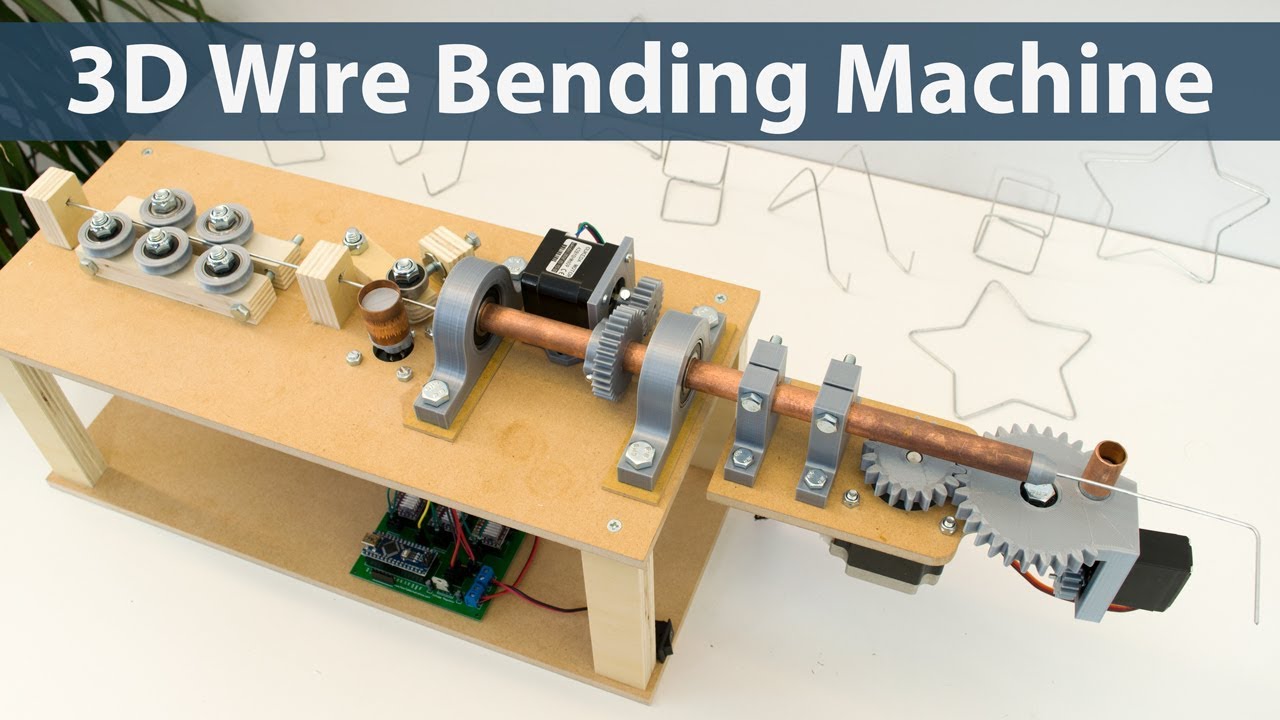
$2 for 10 PCBs (100*100mm) https://jlcpcb.com Circuit, Code, 3D Model and more details here ► https://howtomechatronics.com/projects/arduino-3d-wire-bending-...
 wind drift
I am having trouble with my arduino pro micro board and a barcode scanner.
On my arduino UNO it works just fine.
On the pro micro it somehow does NOT do the setup. (The UNO does)
However it does partly do the loop. It will show 'barcoe button pressed' when I press the button - but it does not read a barcode.
I already tried adding a 400 mah lipo battery to the pro micro board but it does not seem to help
the barcode scanner uses 100 ma when reading
Any ideas what the issue could be or what else I could try?
wet crystal
Maybe one of your jumperwires broke
wind drift
I am using the same wires for the UNO on which it works
And it's kinda weird that it does not start the setup
north stream
That's some fairly awkward code, and has some bugs in it.
wraith current
@wind drift ditch the interrupt code. You should either use the interrupt functions to do all the reading or nothing, but mixing the interrupt code with normal loop code is gonna cause problems.
wind drift
I tried to remove it before but then it didn't work at all somehow
And I found a sort-of-fix for my setup issue. It seems for the micro you have to add 'while (!Serial);'
Now it at least does to setup part
but I stil can't get the barcode to read
I am guessing the micro has problems with softwareserial?
or at least my setup ..
dire barn
HELP Metro 328 on/off switch broke. How can I power without plugging it in the computer?
 storm ibex
Broke how, exactly?
simple horizon
@north kelp I found a cable to use with my arduino uno
Lets try to get this lora heck to work!
north kelp
Yay
simple horizon
Protip: if you can't find your old arduino cable just steal borrow it from your parents print or from your printer.
north kelp
Yep. When's the last time they printed, anyway?
simple horizon
I was the last one that printed on it too lol
north kelp
“Can I ask you for some tech support, dear? I think the printer wire's gone missing.”
north kelp
Which board are you targeting?
simple horizon
uno
north kelp
Well at least it's one of the supported ones!
simple horizon
LIBRARIES THAT COULD NOT BE IMPORTED:
[RF24configs] library.properties not found
[] library.properties not found
back to the desktop ide
north kelp
One of the many reasons I never used Arduino Create.
But it shouldn't be too hard to create a library.properties file:
https://github.com/arduino/Arduino/wiki/Arduino-IDE-1.5:-Library-specification
(possibly dated spec)

GitHub
open-source electronics prototyping platform. Contribute to arduino/Arduino development by creating an account on GitHub.
north kelp
Oooh. Restart.
north kelp
How far does it get?
north kelp
Since you're now using UNO, are you powering the LoRa breakout from 5V?
simple horizon
yes
I did the same wiring as the guide https://learn.adafruit.com/adafruit-rfm69hcw-and-rfm96-rfm95-rfm98-lora-packet-padio-breakouts/arduino-wiring
Radio transceiver modules for long distance data communication
north kelp
Can you show a pic of your wiring?
north kelp
Also, are you using one of the readymade, unaltered code examples, with the Arduino UNO pinout?
north kelp
The RFM9X Test page, and not the RFM69 one, right?
north kelp
I'd run a continuity check from every Arduino pin to it's corresponding LoRa pin, using a multimeter.
Because breadboards and jumper wires. 🙄
I'd also meter across VIN and GND on the LoRa board, expecting 5V from your UNO.
simple horizon
ok
north kelp
Wish there were an LED on the LoRa breakout, but it doesn't appear that there is, according to the primary guide for that product.
north kelp
I'd use the continuity setting of the multimeter, probing from the each pin on the back side of the Arduino to the corresponding header pin on the LoRa.
simple horizon
gnd then to pin?
north kelp
GND to GND, 5V to VIN, MISO to MISO, etc
Basically, testing all 8 jumper wires (and breadboard connections).
simple horizon
ok got it
north kelp
What I'd be hoping to find is that one of the pins - say the MISO pin on UNO, and the MISO header pin on LoRa, there's a flaky or broken connection.
If all the connections are good, then the problem might lie with a damaged LoRa breakout, or a damaged UNO GPIO.
simple horizon
might have found it...
north kelp
Ooh!
north kelp
On the UNO?
simple horizon
no on the other boards.
north kelp
Hmmm.
If you have another SPI breakout lying around (not a LoRa), that could eliminate the UNO as a problem.
simple horizon
I only i2c
north kelp
An SD card you don't care too much about could be good in a pinch for testing SPI.
simple horizon
I have an Accelerometer breakout too
north kelp

Instructables
Cheap DIY SD Card Breadboard Socket: Do you have a project that needs an interface to mass storage, but don't have the resources to build a breakout board for a standard socket? In this Instructable, you will learn how to make an SD card socket that plugs right into a breadb...
simple horizon
GPS board
north kelp
I'd update board support package for Arduino UNO, as well, if needed.
simple horizon
Literally nothing is working
This person on stack said that he just waited for 9 days and came back. It worked after that wait.
simple horizon
Ya, they said they dont know what was wrong but it works now
Radiohead library and rfm95 weird init issues
sorry it was the arduino forms
 trim bane
my flora has been working no problems, just uploaded a sketch and now windows is telling me the device malfunctioned and is not reconized. Rebooted, still a problem. any ideas?
simple horizon
Make sure you got those drivers
trim bane
yea ive got the drivers, ive uploaded about 4 sketches this morning no problem. last one killed it 😐
simple horizon
@north kelp do I have 2 useless lora modules?
I bought it from amazon and obviously soldered the pins to the breakout
north kelp
Hmmm. Sorry about that! I’d contact the seller. Perhaps get replacements working first to strengthen your RMA case with the seller, @simple horizon
north kelp
Well, I think your odds will get better.
simple horizon
I'll buy from adafruit directly
I bought from amazon because it was 5 cents more expensive but I had prime
So free shipping
wraith current
@simple horizon I've had good luck with the adafruit feather board with the radio module already on there.
crystal mesa
@simple horizon did you buy from Adafruit on Amazon?
I've done that in the past and gotten Adafruit support to directly replace a faulty component
simple horizon
@crystal mesa from Amazon
crystal mesa
Yes, but was Adafruit the seller within Amazon?
They sell both directly from their website and as a seller via Amazon.
As far as I know, you're equally entitled to support via either purchase route
crystal mesa
Ah, darn.
simple horizon
Im going to try on my pi just to be sure it's not the code
 radiant vapor
@north kelp oh man that sd socket hurts me
radiant vapor
anyone have recommendations for serial plotters?
north kelp
@crystal mesa As far as I know, Adafruit is not a seller on Amazon; Adafruit products on Amazon are sold by independent third parties.
simple horizon
@north kelp a lot of them are authorized distributors
north kelp
Just for reference, here’s Adafruit’s list of authorized distributors:
Adafruit Industries, Unique & fun DIY electronics and kits : Hacker Spaces/Distributors Map - Tools Gift Certificates Arduino Cables Sensors LEDs Books Breakout Boards Power EL Wire/Tape/Panel Components & Parts LCDs & Displays Wearables Prototyping Raspberry Pi Wireless Youn...
And yeah, I do use Amazon. But there’s also a lot of product there that mentions Adafruit, uses Adafruit images or product names, and may or may not be actual Adafruit product. Caveat emptor.
wind drift
Okay it seems my barcode scanner has the following: Serial port default: baud rate 9600, data bit 8, stop bit 1, no parity, no flow control;
How can I check the bit 1?
In my code
north stream
What, the stop bit?
wind drift
Yes
north stream
Basically the stop bit is sent at the end of the transmission, to provide a little buffer space before the next one begins. Traditionally, some hardware needed one, one and a half, or two stop bits. These days, one is generally plenty. The only real way to check for it is to send two frames in quick succession and examine the time between them to make sure it's no shorter than a bit time.
wind drift
Is there any reference I can follow regarding the timing of the bit?
north stream
Alchitry
Asynchronous serial communication, often shortened to just serial, is one of the easiest ways to communicate between two different devices. In it's simplest form, it consists of just two connections. One line for sending data and the other for receiving data.
 ionic wigeon
hello i am having trouble understanding simple arduino code stuff should i post my question here?
solar sail
Absolutely 😃
north kelp
Welcome, @ionic wigeon !
ionic wigeon
Awesome!
i will take a minute to get the code i was using but for now:
I have found the encoder.h library to have better performance than other examples(should i use it?), but i cannot figure out how to loop counts from 0-99.
I can limit the count to 99, but the next count is 99, i want it to start at 0.
I also want no negative numbers, and when the count is -1 or less than zero it should reverse the loop back to count 99.
Much like a odometer on a car if it could only hold 2 digits.
north kelp
Are you using Paul Stoffregen's excellent Encoder library?
https://github.com/PaulStoffregen/Encoder
GitHub
Quadrature Encoder Library for Arduino. Contribute to PaulStoffregen/Encoder development by creating an account on GitHub.
ionic wigeon
yeah thats the one, this is mostly from his example but modified to add limits, maybe im looking to add a for loop but im at the point of guessing haha
#include <Encoder.h>
Encoder myEnc(2, 3);
void setup() {
Serial.begin(115200);
Serial.println("Custom Encoder Test:");
}
long oldPosition = -999;
void loop() {
long newPosition = myEnc.read();
if(newPosition > 99){
  newPosition = 0;
}

if(newPosition < 0) {
   newPosition = 99;
}
if (newPosition != oldPosition) {
oldPosition = newPosition;
Serial.println(newPosition);
}
}
north kelp
Try something like:
    if(newPosition > 99){
      newPosition = 0;
      myEnc.write(newPosition);
    }

    if(newPosition < 0) {
      newPosition = 99;
      myEnc.write(newPosition);
    }
That shows how you can set the Encoder's counter to whatever you want.
 obsidian jetty
does anyone know how I can control a piezo's tone by using a rotary encoder?
north kelp
@obsidian jetty Here's an Adafruit guide to generating tones on piezos:
https://learn.adafruit.com/using-piezo-buzzers-with-circuitpython-arduino

beep beep boop
I'm also a fan of Paul Stoffregen's Encoder library:
GitHub
Quadrature Encoder Library for Arduino. Contribute to PaulStoffregen/Encoder development by creating an account on GitHub.
 rough geyser
heya. I'm trying to make a quick proof of concept of two trinket M0s talking to each other via their RX and TX pins and I'm not able to get it working.
I created a sketch for each board that you can find here: https://gist.github.com/chris-schmitz/14a7f00ad1efbc86463161f78f508f04

Gist
Trying to get two Trinket M0s to talk to each other - receiver.ino
and then I connected each trinket's RX and TX pins to the opposite pins on the other
(Rx -> Tx and TX -> RX)
but when I open the serial monitor for the receiver board all I get is the text "TestingOpen" broken up across lines
Anyone have an idea of what I'm doing wrong or misunderstanding?
north stream
Serial is the USB serial port, you'll want to send and receive using Serial1 to use the RX/TX pins.
rough geyser
ah, so would I be replacing Serial for Serial1 in my code??
I didn't realize I could do that. (looking for Serial1 in adafruit learning section ...)
north stream
You'll use Serial to talk to the serial monitor and Serial1 to talk between Trinkets. So you'll need both in at least one case.
rough geyser
so similar to this? https://learn.adafruit.com/adafruit-ultimate-gps-featherwing/basic-rx-tx-test

Where are your Feathers at? Now you know!
👏
north stream
Yeah, similar to that.
rough geyser
awesome! thanks!!
that makes a lot of sense
I'll dig in more tonight. Thanks for the point in the right direction 🙇
rough geyser
aw yeah!!
@north stream I got my first set of sketches working via Serial1 and then adjusted it to the proof of concept I was shooting for (which was passing enum values between controllers) and it's working!!
thanks for the help!!
north stream
Nice!
 eternal coral
// set pin numbers:
const int buttonPin = 2;     // the number of the pushbutton pin
const int ledPin =  13;      // the number of the LED pin

// variables will change:
int buttonState = 0;         // variable for reading the pushbutton status

void setup() {
  // initialize the LED pin as an output:
  pinMode(ledPin, OUTPUT);
  // initialize the pushbutton pin as an input:
  pinMode(buttonPin, INPUT);
}

void loop() {
  // read the state of the pushbutton value:
  buttonState = digitalRead(buttonPin);

  // check if the pushbutton is pressed.
  // if it is, the buttonState is HIGH:
  if (buttonState ==HIGH) {
    // turn LED On:
    digitalWrite(ledPin,HIGH);
  } else {
    // turn LED off:
    digitalWrite(ledPin,LOW);
  }
}```i tried to simulate a buton just with wired
so when i touch them the led is going off
but how to make the code when i touch the wires between themselfs to light the led
north stream
Try turning on a pull-up resistor by changing the pinMode statement to ```c
pinMode(buttonPin, INPUT_PULLUP);
 steel aurora
Someone know if its possible to initialize WS2812FX in the setup()?
Tried:
WS2812FX strip;
void setup() {
  strip = WS2812FX(....);
}```
But it doesnt seem to like it: `no matching function for call to 'WS2812FX::WS2812FX()'`The example code shows how to set it up: https://github.com/kitesurfer1404/WS2812FX/blob/master/examples/external_trigger/external_trigger.ino
steel aurora
Yea, but i needed to gather the pin and stuff from WifiManager.
For now i just assign the var a dummy WS2812FX object, then later the one with the right pin etc
north stream
Might be a variable type issue then.
Looks like it wants a uint16_t for number of pixels, a uint8_t for the pin, and a newPixelType for the type value.
That's what it uses to look for a matching function.
There ought to be some more detail in the error message saying what the argument types it's trying to match are.
 gritty moss
Anyone have any experience with arduino serial over bluetooth? I'm trying to get bluetooth to work from my arduino to processing on my computer. So far I've been able to do it over a cable. I tried replacing the cable with an HC-05 bluetooth module, pair it to my pc and set it to the bluetooth com port. Program keeps returning null. I'm using sparkfun's tutorial. https://learn.sparkfun.com/tutorials/connecting-arduino-to-processing/all
pine bramble
Hello everybody. I am trying to clean up my arduino code with my own library.
But I had a question about includes. I am using #include <WebServer.h> library in my main sketch but I am also importing my own library who also uses the librarys functions
Does this mean that I have to include in the main sketch and in the library?
If I don't inlcude I can't compile it
So I guess yes?
Also does this take twice the space?
 forest spear
🤔
north stream
You need to include it in any module that references the declarations.
wraith current
@pine bramble Just imagine an include statement as pasting a huge block of code right on the same line that has the include statement. You only need it once but you might need to put something above something else.
swift fable
anyone have idea if bossac checks USB dev_id ? i cant program through external uart device using bossac and samd21 bootloader both interfaces
 steep totem
Is anyone aware of any issues with the HC-SR04/NewPing library on the Feather M4 when working against the Arduino framework? I know it works fine in CP, but am (probably) missing something obvious in C++ land.
 worn ingot
I got the new course for you. Today is free. How to a matlab😜
 elfin kiln
I uploaded a HID code <Mouse.h> now I get a device error 'Windows has stopped this device because it has reported problems. (Code 43) A request for the USB device descriptor failed.' I uninstalled, reinstalled, updated drivers, tried to roll back driver(not an option). I don't know what else to do. Any suggestions?
north stream
Was just looking at a Matlab-based project.
pine bramble
Hi everybody I am trying to clean up some code by making a library.
But I am getting a error when I want to execute a function.
In the SetupMode.cpp file
I have the following code >>
void SetupMode::begin(int port)
{
    Serial.println("Beginning SetupMode");
    WebServer setupServer(port);

    setupMode_server_config();
    setupServer.begin();
    Serial.print("[SetupMode] => TCP SetupMode Server Started at port:");
    Serial.println(port);
}
However the function setupMode_server_config(); can't be called
'setupMode_server_config' was not declared in this scope
But I do have that function declared like this.
void setupMode_server_config()
{
    //somecode
}
Does it has to do something with the header file?
north stream
Could be. Is setupMode_server_config() a method of SetupMode?
pine bramble
I changed some things.
Also added the functions in the header file. It's doing oke but I get a different error now.
Added this to the header file don't know if this is best practice?
#ifndef SetupMode_h
#define SetupMode_h
#include "Arduino.h"

class SetupMode
{
    public:
    void begin();
    private:
        void setupMode_server_config();
        void handleSetupModeRoot();
};
#endif
And in the cpp file I have this code
#include "Arduino.h"
#include "SetupMode.h"
#include <WebServer.h>
#include <ArduinoJson.h>


WebServer setupServer(8080);

void SetupMode::begin()
{
    Serial.println("Beginning SetupMode");

    setupMode_server_config();
    setupServer.begin();
    Serial.print("[SetupMode] => TCP SetupMode Server Started at port:");
    Serial.println();

}

void SetupMode::setupMode_server_config()
{
    setupServer.on("/", handleSetupModeRoot);
}

void SetupMode::handleSetupModeRoot()
{
    setupServer.send(200, "text/plain", "hello from esp32! this is the setup mode");
}
The error is >>
error: invalid use of non-static member function
     setupServer.on("/", handleSetupModeRoot);
So It can't call it ?
north stream
I think you'll have to make setupServer a class variable. I'm not sure if the handler has to be static or not (I don't think so, as that would be awkward).
pine bramble
I have an rgb LED. How do i know how much power it needs before plugging it in my breadboard. I accidentally blew a red led before cause I forgot to use a resistor
north stream
I'm guessing a plain one (not like a NeoPixel)? Ordinary LEDs generally can withstand a maximum of 20mA or so. Unless I need maximum brightness, I run them at 5-10mA (or lower if I just want an indicator or point of light).
pine bramble
@north stream setupServer.begin() falss under Webserver setupServer(8080)
Its from the webserver lib. Do I also have to declare that function in the header file? The setupServer.begin()
north stream
I'm not sure, but my guess is that you'll have to declare setupServer as a class variable instead of a global one.
north stream
Yeah.
pine bramble
Hmmm would be a logical one true true.
north stream
The SD::init() routine does three things: card init, volume init, and openRoot. Maybe try them individually and see which one is failing?
pine bramble
Uhm aright. Just dont know what your talking about. SD::init()?
north stream
That was in reply to another (now apparently deleted) question from someone who was getting errors initializing an SD card driver.
north kelp
@simple horizon What's the news?
pine bramble
Aright cool.
Hello everybody. and to @north stream
I tried to declare that variable you were talking about but still getting the same error.
This is the header file >>
#ifndef SetupMode_h
#define SetupMode_h

#include "Arduino.h"
#include <WebServer.h>

class SetupMode
{
    public:
    void begin();
    private:
        void setupMode_server_config();
        void handleSetupModeRoot();
        WebServer setupServer;
};
#endif
And this is the cpp file.
#include "Arduino.h"
#include "SetupMode.h"
#include <WebServer.h>
#include <ArduinoJson.h>
#include <ESPmDNS.h>

void SetupMode::begin()
{
    Serial.println("Beginning SetupMode");

    setupMode_server_config();
    setupServer.begin(8080);
    Serial.print("[SetupMode] => TCP SetupMode Server Started at port:");
    Serial.println();
}

void SetupMode::setupMode_server_config()
{
    setupServer.on("/", handleSetupModeRoot);
    setupServer.on("/api/getWifiData", HTTP_GET ,handle_getWifiData);
    setupServer.on("/api/postWifiData", HTTP_POST ,handle_postWifiData);
}

void SetupMode::handleSetupModeRoot()
{
    setupServer.send(200, "text/plain", "hello from esp32! this is the setup mode");
}
And this is the error>>
error: invalid use of non-static member function
     setupServer.on("/", handleSetupModeRoot);
Hmm, perhaps I guessed wrong. That leaves whether on() isn't static (I don't think so), or handleSetupModeRoot() needs to be declared static, or something I missed.
pine bramble
How can I declare a function static ?
Hmmm I don't have any compile errors now. Gonna test it.
This is what I did.
In the header file I declared
static void handleSetupModeRoot();
But in the cpp file just this
void SetupMode::handleSetupModeRoot()
{
    setupServer.send(200, "text/plain", "hello from esp32! this is the setup mode");
}
If I use there also static void ...etc then the compiler throws a error
Because it's already declared static in the header file
north stream
I think you have to declare it static in both places (it has to match).
burnt island
hmm, so you can't use instance variables. Static methods and globals, the 'ol C style
simple horizon
@north kelp i tested the lora modules on my pi and they work
So it's the code i assume
 upbeat basalt
Hi guys. I'm trying to un-dust an Arduino Leonardo that I didn't used for may be 3 or 4 years. When I plug it in my Win7 PC, the Com port for the bootloader comes up then vanished after a few seconds as expected. Problem: the other doesn't comes up.
More over, nothing appears in the Win7 Device Mgr to match the expected PID8036. It's just like the CDC is not mounted. (if I had the device but no driver that I could fix)
wet crystal
Is it an original Leonardo?
upbeat basalt
I successfully compiled and uploaded default blink.
If I add the while! Serial, it freeze
It's a VinciDuino. It used to work exactly as a Leonardo.
wet crystal
Yeah missed the part where you told about the drivers you had used
upbeat basalt
To be sure, I reflashed the caterina bootloader using usbasp
It's not a driver problem because the device even doesn't comes up
There's something I am missing but I can't figure what
wet crystal
Maybe it is the USB Port
upbeat basalt
Not hardware problem as the bootloader ports comes up and I can download blink
May be software
wet crystal
Do you use current arduinoversion?
upbeat basalt
Something like the CDC is not initialized by arduino core
Yes latest 1.8.something
wet crystal
Did you tried to use another serial monitor?
wet crystal
How did you upload your code?
upbeat basalt
Compile and upload. Then press reset button when avrdude started to ping the board. Boooader port came up and blink was downloaded
If I don't include the while loop on serial, it runs. If I include the loop, code freeze in the loop
Which comfirm the CDC serial is not initialized
I will try again later from a fresh Linux PC
See if it makes a difference
upbeat basalt
More testing : it doesn't work properly with the 2 USB 3.0 ports but ok with the 2.0 ports. Weird.
 bleak glacier
@upbeat basalt not familiar with your board but did you set programmer to usbisptiny in the ide and use a data usb cable? A while back there were problems with the clone version of uart chips, don’t recall if that was fixed with a patch. Your board may not be a true Leonardo with atmega u4 chip and using external uart. The later versions of the Ide might need something. Good luck.
 crisp talon
hi im having an issue with the adafruit trinket 5v version
it is giving this error when I try to upload arduino code to it:
Multiple libraries were found for "Wire.h"
Used: C:\Users\edwin\AppData\Local\Arduino15\packages\adafruit\hardware\avr\1.4.13\libraries\Wire
Not used: C:\Program Files (x86)\Arduino\hardware\arduino\avr\libraries\Wire
exit status 1
Error compiling for board Adafruit Trinket (ATtiny85 @ 8MHz).
would anyone know why?
north stream
I think the multiple libraries is just a warning, and the error is elsewhere?
crisp talon
what do you mean "the error is else where"?
north stream
I mean the messages about the libraries are likely not the error, and perhaps there's another piece of output that gives more information.
crisp talon
wait I think I realized the issue:
I am unable to connect to the trinket
I cannot choose a port to sent the code through
there are not port
but the trinket is lights up when connected to the usb
could this be the issue?
if yes how do i fix it
?
crisp talon
nvm I figured it out thank you very much @north stream
north stream
What was the fix (I was out for a walk)?
upbeat basalt
@bleak glacier it is a 32u4 with integrated USB.
Can't understand why the bootloader can properly set up the CDC but the core can only on the USB 2 ports. May be something weird with my 10 years old Dell XPS laptop. That was early days of USB 3 wasn't it?
crisp talon
@north stream Hi, sorry for the delay in response. I am the guy from yesterday and the adafruit trinket issue . The problem ended up being the fact that the reset button had to be pressed on the trinket prior to uploading the code. The fact that there were no ports to connect to I realized that it is normal for the trinket (after fully reading the pdf of the trinket) and all that I had to do was press that button and connect to the right I think programmer which in this case was USBtiny (or some version of USB and tiny)
north stream
Oh yeah, the USB on the AVR Trinket is implemented in software, and it can't do that and something else, so you have to tell it when you want it to emulate USB and then talk to it before it times out. It's a clever hack, but a little tricky.
crisp talon
yeah this was the first time I had ever used the AVR trinket so I did not know about this until yesterday night. 😃
 olive carbon
does "ArduinoISP" work with feathers?
want to burn bootloader onto "ATMEGA1284P" with feather
crystal mesa
@wet crystal You might get a faster response asking in #general-tech or #help-with-projects
upbeat basalt
@olive carbon do you mean an AVR feathers or a different CPU family
At least with an AVR it should work but need to be careful with the cabling. Check schematics
olive carbon
id like to us feather M4 to burn bootloader onto atmega1284p, with the ArduinoISP
i looked up the chip at 12mhz clock speed should be okay with 3.3v.. but its normally 5v logic i guess, will that be an issue?
upbeat basalt
For 5v vs 3.3v you'd better use a voltage translator
olive carbon
alright i can do that
upbeat basalt
Now, on software side, I'm not sure that the original sw which was using an AVR Spi port can run the same on a M4
olive carbon
could i use J-link edu mini? to burn bootloader... like forget the feather? im not sure if it works with atmega1284p
solar sail
Nope.
upbeat basalt
No JLink use a different protocol
I'm not at home so don't have access to an Arduino setup. So I can't check the code now
olive carbon
no hurry, i dont have the atmega1284p board yet. It's on Anet A8 3d printer. I guess some versions of the mainboard dont have a bootloader, so you need something extra to reprogram with marlin, just wondering if i have something already i can use or if i need to buy USBASP or something
crisp talon
Hi I have a quick question about the #include <UsiSerial.h> library from https://github.com/frank26080115/Arduino-UsiSerial-Library/tree/master/UsiSerial
for the adafruit trinket
GitHub
Arduino library to implement hardware serial using USI - frank26080115/Arduino-UsiSerial-Library
how exactly do I download it?
upbeat basalt
Hi @crisp talon , go back to the root of the repository. There is a green button on the right "Clone or Download".
Click and select Download ZIP
You will get a ZIP file. Unzip and move the files to your Arduino Lib folder in a similar way as others existing libs
crisp talon
@upbeat basalt so I did that and in I can see it in the folder but I cannot see it through the arduino IDE
did I do something wrong?
also when I try using #include "UsiSerial.h" it says invlid library found in C:\ ......
north stream
You can bitbang a bootloader with pretty much any board, if the voltages match, it'll just be a little slow. Don't need hardware SPI support.
crisp talon
thanks @north stream I solved it! yay.
but my only issue now is the:Multiple libraries were found for "Wire.h"
Used: C:\Users\edwin\AppData\Local\Arduino15\packages\adafruit\hardware\avr\1.4.13\libraries\Wire
Not used: C:\Program Files (x86)\Arduino\hardware\arduino\avr\libraries\Wire
exit status 1
Error compiling for board Adafruit Trinket (ATtiny85 @ 16MHz).
error from yesterday came back up and the fix I used yesterday by pressing the reset is not helping
north stream
The multiple libraries message is a warning, not an error, fixing it is annoying.
crisp talon
oh so would the program still work?
even though it says error compiling and exit status 1?
north stream
Sort of: there is another error that is causing it not to work.
crisp talon
#include "Adafruit_VL53L0X.h"
#include "UsiSerial.h"
Adafruit_VL53L0X lox = Adafruit_VL53L0X();
void setup() {
UsiSerial.begin();
// wait until serial port opens for native USB devices
while (! UsiSerial) {
delay(1);
}
UsiSerial.println("Adafruit VL53L0X test");
if (!lox.begin()) {
UsiSerial.println(F("Failed to boot VL53L0X"));
while(1);
}
// power
UsiSerial.println(F("VL53L0X API Simple Ranging example\n\n"));
}
void loop() {
VL53L0X_RangingMeasurementData_t measure;
UsiSerial.print("Reading a measurement... ");
lox.rangingTest(&measure, false); // pass in 'true' to get debug data printout!
if (measure.RangeStatus != 4) { // phase failures have incorrect data
UsiSerial.print("Distance (mm): "); UsiSerial.println(measure.RangeMilliMeter);
} else {
UsiSerial.println(" out of range ");
}
delay(100);
}
I'm trying to run a vl53l0x on the trinket
north stream
What you (still) need to do is find the actual error message.
crisp talon
where would it say the error?
I'm looking through the orange text from the error message and its not directly saying anything that I can see
oh now i see the error messages
it says serial not declared in this scope
repeatedly
why would it state that if serial was never used?
north stream
I'm not familiar with UsiSerial, perhaps it uses Serial internally?
north kelp
@crisp talon Two issues:
• It looks like Adafruit_VL53L0X uses Serial internally. (As do a ton of Arduino libraries.) You might code like Serial.begin(9600); in your setup() to keep that sensor library happy.
• You probably also need to work around the lack of hardware serial support for ATTiny85 by doing something like #define Serial UsiSerial
https://github.com/adafruit/Adafruit_VL53L0X/blob/master/src/Adafruit_VL53L0X.cpp
GitHub
Arduino library for Adafruit VL53L0X. Contribute to adafruit/Adafruit_VL53L0X development by creating an account on GitHub.
upbeat basalt
indeed the driver code is using Serial.print() for debug.
Change the top of your code :
#define Serial UsiSerial
 #include "Adafruit_VL53L0X.h"
...```
That will force the `Serial.print()` in the driver to use `UsiSerial`And don't forget to use triple back quote around your code like :
```
your code
```
crisp talon
@upbeat basalt so I added the #define Serial UsiSerial
so do I need to change all the Serial to Usi Serial?
or this question also goes to @north kelp
upbeat basalt
No, the #define does that for you
it's like a search-andè-replace performed during the compilation
that's why you need to place the things in that order
crisp talon
@upbeat basalt okay that makes a lot of sense:
I asked that question because there is a new error that pops up:
no matching function for call to 'USISerial::begin(long int)'
so I thought that this issue was due to the lack of Usi.
would you know why this new error pops up?
upbeat basalt
I think you are missing something. Is there any sample code for UsiSerial ?
It looks like this is a C++ object and you may not use it correctly
Sorry I have to switch to something else for the rest of the evening (EU time)
crisp talon
thank you very much @\
@upbeat basalt
@north kelp I was looking at the link that you put what is it for.
I understand it is for the VL53l0X but is it specifically for the trinket or what?
 serene solar
Hi, just jointed and have a question to ask! Anyone used a Adafruit Sound FX Board ?
joined woops 😂
north kelp
@crisp talon That's the source code for the VL53L0X library that you're including in your project. I like to look at the library source to troubleshoot.
Also, try just Serial.begin() in your setup(), since UsiSerial doesn't take a baud speed argument in its begin() method.
And here's where I point at the relevant source code for UsiSerial. :-)
https://github.com/frank26080115/Arduino-UsiSerial-Library/blob/master/UsiSerial/UsiSerial.h
GitHub
Arduino library to implement hardware serial using USI - frank26080115/Arduino-UsiSerial-Library
Note the comment on the line that defines begin().
Often the library source code includes good hints that the documentation lacks.
crisp talon
so I saw the: AVR307 does not calculate baudrate at runtime, set the baudrate in USI_UART_config.h
how do i set the baudrate in USI_UART_config.h?
north kelp
Well, let's take a look at UIS_UART_config.h!
https://github.com/frank26080115/Arduino-UsiSerial-Library/blob/master/UsiSerial/USI_UART_config.h
GitHub
Arduino library to implement hardware serial using USI - frank26080115/Arduino-UsiSerial-Library
It looks you can uncomment the #define BAUDRATE line you'd like to use. Note the helpful comment for 19200: // tested and works on 16 MHz Trinket
crisp talon
@north kelp this is a preemptive apology: sorry for all the stupid questions I am asking I am very new to this arduino in general
so my current question is that I see the github file but how do I use it? should I use it as a library?
north kelp
Absolutely no apology needed. We are all learning here!
You are already using it. What you’re looking at is the source code for the libraries you’re importing into your sketch.
The Arduino Library Manager pulls this source in from repositories like GitHub.
It also gets copied into your Arduino Libraries folder on your PC.
You can also create your own library from a snippet of code you find yourself using across projects.
Libraries are basically just more Arduino code, like what you already write in your sketches.
crisp talon
so how would I now go into the library to change the baudrate?
north kelp
I would leave it at the default 19200 baud.
But if you want to change it, it's in your Libraries directory.
On Mac, that's in Documents/Arduino/libraries/UsiSerial
On Windows 10, I think it's in Documents\My Documents\Libraries\UsiSerial
On Windows, there may be an Arduino\ in that path, before Libraries\
crisp talon
awesome I will try that tomorrow morning and i'll see if that works
i probably will have more questions after that :)
thanks so far!
 languid jacinth
Good evening everyone. I was able to get Johnny-five successfully working with my library by blinking the red LED. I now want to be able to communicate with the neopixel in javascript. I don't think I can use the libraries that are available in the arduino lib manager because they are in Scratch. What alternatives do I have? thank you!
 worn delta
guys I'm using the wonderful Adafruit GFX to render some chars and images on my SSD1306 OLED display
is there some examples on how to retrieve images from SPIFFS without the needs of cabling it inside my sketch?
 flat fog
is there a way to write to many pins at once, with one line?
say I have a 8bit value that holds 8 values for 8 pins, is there a faster way than calling digitalwrite 8 times?
 spice nacelle
crisp talon
spice nacelle
crisp talon
@north kelp so I was able to check out how to change the baudrate I did not change it I was curious how it could be done.
now with the trinket issue:
it still says that there Serial was not declared in this scope
so from what you said I don't need to change the baudrate to solve this issue so how would I?
north stream
Did you add the #define to re-define Serial?
crisp talon
yes yes I did
north stream
It may be that the library is compiled separately, and will need to be built to use the alternate serial port.
crisp talon
alternate serial port?
north stream
Yeah, the ATtiny doesn't have a hardware serial port, which I'm guessing is why you're using the UsiSerial alternate serial port.
worn delta
guys I want to use bitmap images on my OLED display. is it better to store images on the file system of my arduino or it is better to copy images in char array and store them in PROGMEM?
or it is equivalent?
I would like to have as much space as possible for my sketch and use file system for images
does this have sense?
or am I wrong in something?
north stream
An ordinary Arduino has three kinds of storage: RAM, flash, and EEPROM. I'm not aware of it having a file system unless you add something like an SD card or a bigger flash chip.
The usual approach is, yes, to store images in flash (which is the same as PROGMEM, that's where your executable code lives too). In practice, it's much more common to run out of RAM than flash. If you're writing really big sketches that eat up most of the flash, then it might make sense to add external storage (another flash chip, SD card, etc.) to hold images.
crisp talon
so @north stream since you said the libaray needs to be built to use the alternate serial port does that mean it is not built for the alternate serial port
?
 ocean zodiac
Feeling frustrated with my Metro MO Express board. I cannot form serial connection with a formatted 2GB SD card on ChipSelect 10, yet my Arduino UNO Board can establish connection. https://forums.adafruit.com/viewtopic.php?f=25&t=151472&p=750658#p750658 I’m moving this post here because I have not loaded CircuitPython back on yet. Any suggestions?
north stream
Right, I'm guessing the library is built for a standard serial port, which the ATtiny CPU does not have.
crisp talon
so basically I cannot use the adafruit trinket for this project?
north stream
I think the Metro M0 has its SPI pins in different locations than the Uno, so connecting it to an SD card will be different.
You can use it, but you'll have to build a variant version of the library to do so.
crisp talon
sorry @north stream
I need some clarification here you stated was your previous post's "you can use it, (...) to do so." referring to my earlier question or was all of your previous post referring to @ocean zodiac ?
north stream
Yes, @crisp talon I was clarifying that you can use the Trinket with this library, but the library will have to be converted to use the other serial library.
crisp talon
okay awesome! so I would need to convert the library to use the alterntae serial port?
north stream
Right. Fortunately, it's an easy enough conversion.
crisp talon
sorry for this stupid question (since this thread I so long I'm slightly confused)
are we refering to the vl53l0x library?
north stream
I don't remember. Whichever library that was using Serial.
crisp talon
yeah I checked its the vl53l0x
as a side note once I have updated this library where could I post this code? is there a specific label I should give it in Github so that others can find it easily?
worn delta
@north stream ESP devices has SPIFFS that is a file system. they have physical memory, suppose 4MB, with this 4MB you have a part for the sketch, a part for the Wifi, a part for the OTA and a part for the file system.
north stream
Ah, not a standard Arduino then. In that case, there ought to be room for a big sketch and your images too. Depending on how it's divided up, images might go in the progmem part or the filesystem part (I'm guessing the filesystem part).
 willow dirge
I'm working on an arduino project that reads in serial data from a GameCube controller. I've got it to the point where I have every bit of data in an array of booleans called rawData[]. The data string is 90 bits long. There's some sections of the string that map onto 8 bit values for the joystick potentiometers. So let's say bits 40-47 are the 8-bit value of the joystick x axis.
I want to transform those 8 booleans into unsigned 8 bit integer and display it as a number from 0-255 on the serial monitor. How do I convert the 8 booleans to an integer I can easily read?
north stream
Depends on whether they're stored as bits or booleans.
willow dirge
They're stored as booleans
north stream
Something like this (I'm guessing which is the most significant bit)? ```c
result = 0
for (bit = 40; bit <= 47; ++bit) {
if rawData[bit] {
result |= 1;
}
result <<= 1;
}
Serial.print(result);
@north stream thanks for the reply, I'll try it out
 random oyster
hey guys, I'm wondering if any of you have had trouble reading the COUNT register of a TC on the SAMD51? I'm doing this right now, which seems correct, but always returns 0.
/* Issue the read sync command so I can read the counter */
TC2_REGS->COUNT16.TC_CTRLBSET |= TC_CTRLBSET_CMD_READSYNC;

/* Wait for synchronization */
while ((TC2_REGS->COUNT16.TC_SYNCBUSY));

/* Read the counter value */
uint16_t counter = TC2_REGS->COUNT16.TC_COUNT;

// counter is now equal to 0 - why?```what arduino library supports the itsybitsyM4?
north stream
Most of the Arduino libraries I've tried have worked with the ItsyBitsy M4.
narrow thorn
is pin 5 just 5?
and I can;t seem to get programs to upload.. never had issues on my CPX nor GrandCentral
north stream
Pin 5 is special: it's an output-only pin that's level shifted to 5V.
narrow thorn
right
but what do you call it in a sketch?
#define DATA_PIN 5
is what I am trying
but is that right?
north stream
Yeah, I think it's just 5, not D5 or something.
pine bramble
I wonder how you connect an arduino to a raspberry pi or is it better to think out of the box and do it over wifi/bluetooth?
narrow thorn
also how many time do you hit reset so it will allow the arduino gui to upload?
I neverhad issues with my CPX nor GrandCentral.. but I keep getting errors on uload.. not compile
north stream
There are a few ways to hook an Arduino to a Pi. You could use asynchronous serial or SPI. Note that if it's a 5V Arduino, you'd need to do level shifting. And yes, WiFi/Bluetooth should work too if they have those interfaces.
My Itsy is downstairs so I can't try it right now, but I don't remember it being particularly difficult (basically the same as a CPX or Grand Central).
pine bramble
it's the mega 2560 if it matters
narrow thorn
In the arduino gui you select the board you are uploading to.. there is only an adafruit CPX as a adafruit choice.
very odd.. I reinstalled arduino frm scratch and removed all libraries.
I only enabled fastled.. I would think I would need to tell it about being a SAMD51.. but I see no options like they are mentioned in learn
omg.. there is a difference between libraries and boards being managed. sigh...
north stream
Yeah, that. You need to install the Arduino SAMD board packages, as well as the AdaFruit SAMD board packages (which depend on the Arduino ones).
I think the Mega 2560 is available in 5V and 3V versions: the 3V can talk to the Pi without a level translator, the 5V needs level shifters.
narrow thorn
I got it working!!! Including fastLED with the itsybitsy M4
now I need to issue a PR to fastLED to get the fixes pulled in.. I didn;t make them, but the person that did has gone missing... weird.
pine bramble
adafruit don't seem to sell arduino/pis in canada unfortunately unless amazon won't show them to me. Is it still ok to be here?
I'm actually going to build my pi this time instead of picking a pi kit depending on if my laptop wants to play nice
north kelp
@pine bramble Adafruit does ship internationally. See the shipping info page:
https://www.adafruit.com/shippinginfo
Adafruit Industries, Unique & fun DIY electronics and kits : Shipping & Returns - Tools Gift Certificates Arduino Cables Sensors LEDs Books Breakout Boards Power EL Wire/Tape/Panel Components & Parts LCDs & Displays Wearables Prototyping Raspberry Pi Wireless Young Engineers ...
 honest obsidian
Need a bit of help understanding best practices for pass by reference vs. pass by pointer vs. pass by value. A CS friend I spoke to (works on games, not microcontrollers) recommended pass by reference or const reference instead of pass by value since pass by value has to allocate memory, which is slower than simply passing an address to memory. A couple posts on stack overflow appear to suggest that pass by pointer is only more useful than pass by reference when NULL is useful information. But then I found some conflicting info that suggests that pass by value should be favored over pass by reference unless the data types are large e.g. strings, vectors, etc. I found something else that said pass by reference is just a disguised version of pass by pointer, so pass by pointer is more efficient than pass by reference (specifically with microcontrollers). Can anyone chime in on this? I'm using a SAMD21 microcontroller while programming in the Arduino IDE v.1.8.8 on Mac OSX High Sierra 10.13.6.
north stream
Pass by pointer is basically the same as pass by reference. It does depend on what you're passing, and if you want it to be mutable. If you're passing a byte, that's one byte, no problem. A pointer/reference to a byte is 2 bytes, which is more. If you're passing a 50-byte item, a pointer is still 2 bytes, but the item is 50.
Another wrinkle is if you want to modify the value. If you pass a byte and modify it in a routine, that change is lost when the byte is deallocated when the routine exits. But if you pass a pointer to a byte and modify the (pointed to) value, the change will persist. C strings (which are character arrays and therefore pointers) are normally passed by reference/pointer anyway. C++ strings (which are objects) I'm less sure, but I think they're passed by reference as well.
The NULL/no value case can matter too: it's tricky to distinguish a zero value from "no value" unless you choose a special value that won't be a valid one. With pointers, a zero (null) pointer is nearly always not valid, so gives a fairly consistent way to specify "no value".
Whoops, you said SAMD, where I think pointers are 4 bytes. The rest is germane, just pointers are a different size.
Another persnickity note: bytes are often promoted to ints when passed as arguments, to simplify argument framing, so passing a 1-byte value can really end up being a 4-byte value on the stack.
honest obsidian
Does pass by reference require less instructions on the backend than pass by pointer?
north stream
Again, references are basically the same as pointers in this context.
I'm guessing that C++ object references (handles?) are implemented as pointers, but I'll admit I'm unclear on the C++ details (generally when I'm optimizing for performance, I use straight C).
honest obsidian
I was under the impression that when you pass by reference, the reference will need to dereferenced (I think that's the proper term) which is an extra step.
north stream
Ah, I misunderstood what you were asking. From a "number of instructions" standpoint, it's pretty close, as the SAMD instruction set has instructions that support "indexed addressing" which is what is normally used when dereferencing a pointer variable.
However, it may take an extra clock to execute (I'm not sure on that detail), and frequently accessed variables will be placed in registers anyway for quickest access (SAMD has lots of registers available for this sort of optimization).
But for detailed cycle count performance analysis, you'd have to write a little test code, work around the optimizer, examine the resulting assembler and then check the performance either with an in-circuit debugger, an emulator, or the CPU data sheet.
With the optimizer enabled, there's likely to be a disconnect between what your program specifies and what the compiler actually generates (stack vs pointer is the sort of thing the optimizer will pick up and rearrange for you).
There's a decent writeup of how modern compilers (and CPUs) make C no longer a "low level language" here: https://queue.acm.org/detail.cfm?id=3212479
honest obsidian
Do you mind if I ask which route you usually take when passing a variable to a function? I think you mentioned that you usually write in C not C++.
north stream
Like I alluded to, it depends on the size of the variable and what I'm doing with it. For small variables (ints and the like), I generally pass by value, unless I want to modify the variable in the subroutine, in which case I either use a pointer or return the modified value. For large variables (strings, structs, and the like), I generally pass by pointer.
I also use the trick of passing by pointer when I want to use a zero (null) pointer to flag "no value".
honest obsidian
Got it. Makes sense. Thanks.
I guess i’m just trying to figure out best practices so that if I ever need to do really optimized code later down the road, my code will translate well. But from what you’re saying, it sounds like there’s no exact approach to get the most efficient code. It takes a bit of finicking and is fairly context dependent (also dependent on the MCU's architecture and specific ways of handling memory, etc).
north stream
If you're curious about what's actually happening, even if you don't know (or want to know) assembler, it can be instructive to write a short sketch and examine the assembly code the compiler generates from it.
The rules of thumb I mentioned do a good job of exactly that: they give reasonably optimal code in most circumstances. I come from an assembly language background, so I did a lot of playing with things to learn how to express myself in C. I learned a few bizarre habits like declaring most of my variables and routines as "static" along the way, using the "const" keyword a lot, etc.
I used to use the "register" keyword too, but nowadays I leave that to the compiler.
honest obsidian
Thanks for the input. Checking out the assembler sounds fun.
north stream
I encourage it. BTW, a sample of some code I wrote recently: ```c
static const char * Myid = MYID;
static boolean charging;
static Scheduler scheduler; // scheduler instance
static char *
strcasestr(
const char * s,
const char * find)
{
There's a lot of syntactic sugar there, which makes it a little harder to read, and I'll admit I'm unsure if that sort of thing has a useful effect with a modern compiler but like I said, it's a habit.
barren scaffold
(And this is why I stay in Python, basic caveman C, or recent C++ standards (rarely))
north stream
That makes sense: most people just want to Get Stuff Done. I just happen to have the side quest of wringing out a little more performance, so I end up looking at stuff like ```
loop:
@ args = 0, pretend = 0, frame = 16
@ frame_needed = 1, uses_anonymous_args = 0
push {r7, lr}
sub sp, sp, #16
add r7, sp, #0
ldr r3, .L39
ldrb r3, [r3]
uxtb r3, r3
cmp r3, #0
beq .L15
ldr r3, .L39+4
ldr r2, [r3]
ldr r3, .L39+8
ldr r3, [r3]
cmp r2, r3
beq .L15
Wife's had an assembly class, and a survey of programming languages/paradigms class. Was interesting to see varying gcc optimization levels make increasingly compact assembly.
I appreciate the work that goes into it, but that's no way for most engineers (mechanical, chemical, etc.) to live.
north stream
The code above sheds some amusing light on how things are done under the hood. The relevant code is ```c
static volatile bool tick = false;
void
loop()
{
int tmp; // temporary variable used for swapping
int newfreq; // new sample frequency
int newscale; // new scale factor
struct sbuf * tptr; // temporary write pointer
if (tick) {
// time to update signal, check if data available
if (rptr != wptr) {
So "tick" is a boolean value (true or false). It could fit in a single bit. However Arduino uses a byte to store a boolean. Let's see how it gets stored by the M4: ```
.L39:
.word _ZL4tick
.word _ZL4rptr
.word _ZL4wptr
It's taking an entire 32-bit word!
Looking at the assembler, it puts the value of .L39 (the address of the "tick" variable) into R3 with ldr. It then uses indexed addressing to load just a byte (with ldrb) into R3 at the address of R3. It then does an unsigned sign extension (uxtb) to convert the byte value into a (32 bit) word value, then compares it to zero with cmp. A lot of work for a 1-bit flag!
 errant geode
I write code that displays image on my esp32 (240Mhz, 520Kib sram), and it takes about 250ms to render 160x160 (fullscreen) image (using st7735 library):```cpp
void DrawBmp(String Image, int x, int y)
{
File BmpImage = SD.open(Image);
BmpImage.seek(0x12);
int ImageWidth = BmpImage.read();
BmpImage.seek(0x16);
int ImageHeight = BmpImage.read();
BmpImage.seek(0x36);
uint8_t SdBuffer[480];
uint16_t LcdBuffer[160];
for(int i = 0; i < ImageHeight; i++)
{
BmpImage.read(SdBuffer, ImageWidth3);
for(int j = 0; j < ImageWidth; j++)
{
LcdBuffer[j] = Screen.color565(SdBuffer[j3], SdBuffer[(j3)+1], SdBuffer[(j3)+2]);
}
Screen.startWrite();
Screen.setAddrWindow(x, (ImageHeight-i)+(y-1), ImageWidth, 1);
Screen.writePixels(LcdBuffer, ImageWidth);
Screen.endWrite();
}
BmpImage.close();
}```So, it is average 4-5 fps. Thic code loads one line of image, then send it to screen. I try load more lines, but this not speed up loading images. It is possible to speed up this code even more?
barren scaffold
If you take SD reading out of the code (say you just paint a solid random color), do you get better than 4-5 fps?
north stream
Hmm, the ST7735 library uses the ST77xx library, which in turn uses the SPITFT library, which looks like it might use the old slow digitalWrite SPI on ESP CPUs. It does look like there may be a way to use hardware SPI, and perhaps tweak the SPI frequency (assuming the ST7735 can keep up).
errant geode
@barren scaffold I replace cpp BmpImage.read(SdBuffer, ImageWidth*3);withcpp for (int j = 0; j < ImageWidth*3; j++) { SdBuffer[j] = 123; }and now it takes 30ms to load grey screen, so now it is 30+ fps! So the problem is with BmpImage.read(...). So, how can i speed up read from sd card?
barren scaffold
Don't know offhand, but now you've got a much smaller problem space to troubleshoot.
errant geode
Ok, thanks
barren scaffold
Only thing I can think of is to calculate how many bytes you're reading overall, and get that into a bytes/second rate you're experiencing. Could try a few different image sizes to see if you're really constrained by file size or some other housekeeping or overhead (if reading an image of half the bytes takes considerably more than half the time, you've got a lot of overhead somewhere).
At least on my PyPortal, writing to SD over SPI goes around 7 kB/s. Not sure about reading. But I don't have to update my display more often than once/hour.
Could do the same kind of testing on reading 1 row versus N rows of the BMP, without displaying anything. Does N rows take N times longer to read?
north stream
You could look at a faster SD layout, a more efficient image format, a faster (QSPI?) SD interface, or another form of storage (FRAM?), I suppose.
worn delta
no one is able to retrieve a BMP image from the SPIFFS and then shows the image on the OLED display using Adafruit GFX library?
 magic field
if you say so.
worn delta
@hybrid bear are you able? 😄
barren scaffold
If the intended meaning was "does anyone know how to do X?" or "I'm having trouble with X", you'll likely get better results by preparing a minimal example using the advice at https://stackoverflow.com/help/minimal-reproducible-example
Stack Overflow
Stack Overflow | The World’s Largest Online Community for Developers
north stream
Agreed. Even more so with "Has anyone done X?" If I haven't done whatever it is, I'm unlikely to reply at all, since "I haven't" doesn't add anything useful.
 brazen idol
Does someone know why the Arduino ide is saying that?
burnt island
the infernal semi-colon between the ) and { ended that if statement. Remove it
brazen idol
Thank you! It works
worn delta
Is there someone who can explain me the best way to print to serial even inside tbe loop?
Is it better to use F () macro or PROGMEM? Are there any cons in using F() macro?
magic field
F() is magic and only things marked as being able to handle the F() magic should use it
worn delta
@magic field so should I use F() everywhere I print to serial or to display?
Even inside a loop?
magic field
sure, why not?
worn delta
Flash space will be maxed out ? @magic field don't know this is why I'm asking :)
worn delta
is it ok to use F() macro on a loop that draws an OLED screen every 200 ms? or it will wear my flash memory in less than a year?
north stream
Reading from flash doesn't wear it out, only writing. So printing a string stored in flash doesn't cause any wearout. Remember, your program code is running from flash too, so it's accessing the flash (for reading) at a high rate, but happily this doesn't cause a problem.
I have become very fond of the MSP430FR CPUs which use FRAM instead of flash for non-volatile storage. FRAM is like magic, you can use it just like RAM (up to 8MHz), it's fast, you can read and write, it doesn't wear out, and it's non-volatile like flash.
iron shell
Hello!
I ordered the Adafruit Airlift breakout to be able to add WiFi to my Arduino Mega. I want to use Blynk so I can use an app to toggle a var in my code. I'm on the blynk examples and not sure what to do. I selected Arduino Mega as my board but what do I chose for the connection since Airlift is not on there?
https://williamd.co/u/bhm6.png

 quasi edge
Is there a win application, wicg gives me the ability to change my arduino code live and with a simple UI so that I dont have to go into the code to change a variable?? I mean so I can address a variable to a simple button
barren scaffold
Live variable changes won't be easy for the usual way Arduinos work: a new sketch would have to be uploaded, Arduino gets reset, new setup() and loop() functions are run.. If you wrote a sketch that communicated over serial to the PC with some defined protocol, it's possible that a separate program on the PC using that protocol could set variable values. But that's a more complicated sketch than you might want to develop.
 nocturne ivy
that sounds like an http server on, say, an esp to me...
swift fable
but if the variable is defined globaly would we have constant address everytime we reset the mcu? doesnt this give us a way? to send address amd value .. and the code change it?
pine bramble
I was wondering if the public domain us navy electronics books are still good to learn even thought they are 40 years old?
north stream
For the most part, yes: physics hasn't changed, and the basics are still the same. Some of the emphasis is different today, and it's easier to get access to good test gear, but they're not a bad way to get a grounding.
pine bramble
they dont seems to talk about chips or gpios and various way to talk to sensors and ports thought
my limited understanding of electronics is that it is about being able to make a black box chip do something and get a reading. My only experience is an intro grad robotics course where we were calibrating real-world sensors with matlab and filtering/multi sampling sensors readings up to computing a kalman filter
pine bramble
We didnt do anything practical thought as they would have needed to charge much more for the coursr to pay for labs
north stream
That's the "emphasis is different today" part. The basics (current, voltage, circuits, how capacitors, inductors, and resistors work, voltage dividers, etc.) are all the same. However, active devices have gone from vacuum tubes to transistors to ICs to single-chip CPUs and microcontrollers. They may cover early GPIO chips (often called something like "PIA") and serial adapters (often called something like "ACIA" or "UART"), but the level of integration was lower then.
It might seem that all the basics aren't as relevant now with digital logic, but when you're doing something simple like lighting an LED or measuring light or temperature with an analog port, you are faced with details like current limiting resistors and voltage dividers.
pine bramble
So before I accidently destroy the mega 2560 can all the stuff done on a uno in the starter kit books be done on it?
 proper thicket
I have a bit of an issue programming my circuit playground express and I would really appreciate if somebody could help me because I'm stressing out
#include <Adafruit_Circuit_Playground.h>
#include <Adafruit_CircuitPlayground.h>

volatile bool state = false;

void change()
{
    state = CircuitPlayground.rightButton();
}


void setup()
{
    CircuitPlayground.begin();
    attachInterrupt(digitalPinToInterrupt(5), change, CHANGE); //Pin 5 is labled as the button B
}


void loop()
{
    if (state)
        CircuitPlayground.setPixelColor(4, 0, 255, 0);
    else
        CircuitPlayground.clearPixels();
}
the code above works perfectly
Whenever I press button B the neopixel lights up
However when I change pin 5 to pin 4 (which is the left button)
#include <Adafruit_Circuit_Playground.h>
#include <Adafruit_CircuitPlayground.h>

volatile bool state = false;

void change()
{
    state = CircuitPlayground.leftButton();
}


void setup()
{
    CircuitPlayground.begin();
    attachInterrupt(digitalPinToInterrupt(4), change, CHANGE); //Pin 4 is labled as the button A
}


void loop()
{
    if (state)
        CircuitPlayground.setPixelColor(4, 0, 255, 0);
    else
        CircuitPlayground.clearPixels();
}
It doesn't work at all, which is confusing me because on the playground express pinout button A is labelled as an interrupt pin
in AppData\Local\Arduino15\packages\arduino\hardware\samd\1.6.21\variants\circuitplay\varient.cpp line 124 says that the left button has no interrupt (which doesn't match the pinout)
however any attempt to change the file (even just adding a comment) seems to give me a million errors when I compile my program
Help would be appreciated because I'm really stressing out
pine bramble
How do I know 220 ohm is the right resistor for a led? I did my calculation with ohm law to get the right mA according to the datasheet and it comes closer to 600 so I wonder how the arduino book calculated it
narrow thorn
@pine bramble : I used a 500 Ohm for my play/tests and it worked great. Using a GrandCentral and a diffuse 10mm led.. using pwm from a digital pin.
I think you have bit of flexibility there
pine bramble
I'm wary about the book because it seems to have fatal errors according to forum posts (ie: doing what it says can kill your board) so I'd rather calculate some things myself
pine bramble
Same attitude I have in programming where I don't copy-paste code I don't understand
I already have my hardware that I didn't get from adafruit. Shipping seems to be 15-20$ on any order no matter how small so I'll accumulate a bunch of things and place one giant order
atm I have a mega 2560 from elegoo, an official uno rev 2 and a canakit rapsberry pi 2b
narrow thorn

A detailed introduction on how to use LEDs
proper thicket
and my issue gets washed away :(
pine bramble
That seem a great tutorial thanks
I'll leave the channel to uninspired 😃
@proper thicket if the code above is correct the index of the led seems to be one off the gpio
proper thicket
wdym?
pine bramble
attachInterrupt(digitalPinToInterrupt(5), change, CHANGE); //Pin 5 is labled as the button B and CircuitPlayground.setPixelColor(4, 0, 255, 0); vs attachInterrupt(digitalPinToInterrupt(4), change, CHANGE); //Pin 4 is labled as the button A CircuitPlayground.setPixelColor(4, 0, 255, 0);
Possibly Shouldn't the second one be digitalPinToInterrupt(3) ?
Trying to find the circuit of the neopixels, I suspect you are using the wrong pin number
proper thicket
I'll try digitalPinToInterrupt(3);
pine bramble
wait
the other button is pin #19 according to the diagram I found
so try with attachInterrupt(digitalPinToInterrupt(19). Let me attach an image
pine bramble
right, seems like I had the wrong diagram
pine bramble
I don't know
proper thicket
I'm stuffed
I don't know why that pin isn't listed as an interrupt when the diagrams on the adafruit website say it is
pine bramble
the text says so as well
proper thicket
maybe I should ask someone from adafruit?
north stream
The diagram says D4/left is interrupt 8, but interrupt 8 is GPIO 1/A7. Looks like the diagram is wrong.
proper thicket
@daring marsh we've encountered an error
daring marsh
whats the problem?
proper thicket
We think the pinout diagram for the circuit playground express is inaccurate
north stream
It does say right on the page "The diagram above is not definitive! "
proper thicket
why wouldn't it be definitive
north stream
My understanding is that AdaFruit does not make those diagrams, someone else is making them as a favor to AdaFruit.
daring marsh
which diagram?
proper thicket
Make faster and easier than ever with MakeCode, code.org CSD, CircuitPython or Arduino!
daring marsh
yeah thats probably wrong, the person disappeared
pine bramble
Kinda odd that you can buy something without having a good doc on how to wire it
daring marsh
id like to just delete it
if its significantly in error
cause we dont have any way to edit it
north stream
Perhaps I should dust off my diagram making software?
proper thicket
The issue is that button A is labelled as an interrupt pin when it's actually not
I've spent ages trying to get it to work
daring marsh
oh wait no it is, its IRQ8
you can update teh variant.cpp
{ PORTA, 28, PIO_COM, PIN_ATTR_NONE, No_ADC_Channel, NOT_ON_PWM, NOT_ON_TIMER, EXTERNAL_INT_NONE }, // GPIO D4 / Left Button
to EXTERNAL_INT_8
see if that works?
proper thicket
I tried that before
Anytime I edit that file I get errors
even If it's just adding a comment
daring marsh
could be your editing software is not good
daring marsh
adding weird characters?
proper thicket
maybe
north stream
Hmm, GPIO 1 is listed as EXTERNAL_INT_8
daring marsh
changing just EXTERNAL_INT_NONE will not cause an error
proper thicket
I'll try notepad
daring marsh
to EXTERNAL_INT_8
pine bramble
Maybe vscode think the right plugin to use the cpp is the arduino code plugin...
I've used visual studio for ages and vscode seems to get easily confused
proper thicket
I tried editing using notepad and I verified the code and got no errors so that's a plus
I'm uploading it now
It works!
thanks
Editing with vscode was the issue it seems
pine bramble
either you have to change the encoding in the c++ extension plugin or you don't have a c++ extension so it reverts to the arduino code extension
ie: it might be trying to read c++ code with an arduino code extension so it would show a ton of errors and wouldn't show anything until you modified the file
proper thicket
maybe a note should be added about that interrupt
pine bramble
they will probably just fix the code in the github
daring marsh
please open an issue here
or better, a PR
GitHub
Contribute to adafruit/ArduinoCore-samd development by creating an account on GitHub.
proper thicket
will do
pine bramble
So for those leds the min is 140 ohm still doesnt explain why they say 220
220 seems to be 65% brightness
ElectroDroid also says 150
I hate when a tutorial says a random value and doesn't explain why
pine bramble
Not sure how breadboards works but those are in parallel right? 3 leds taking 2V each shouldn't work in series with 5V
barren scaffold
They’re in parallel, yes. So they each get the 2 V, and pull current independently.
pine bramble
How can you tell just looking at the breadboard?
barren scaffold
If you have a multimeter, can use its continuity tester to verify which breadboard holds are connected.
pine bramble
is it because they are on the same column?
barren scaffold
In that diagram’s orientation, vast majority of the time, the outermost 2 columns are continuous. And each row of 5 is continuous on each side of the center line.

Diagrams, tips and tricks to take you from beginner to brilliant
pine bramble
It doesn't talk about series vs parallel on a breadboard which is basically what I can't figure out. If you told me to change the above to 9V I could do it. If you told me to change it to 9V and make the leds in series I have no idea what to change on the breadboard
barren scaffold
Can you draw the circuit diagram for series versus parallel?
pine bramble
yeah add 3 squares
best way to describe it without a pic
ie: series would be a rectangle, parallel would be a rectangle with 3 squares/rectangles in it
barren scaffold
So components in parallel are effectively tied together at one point in the diagram, right?
pine bramble
yeah I don't know if it's the right terminology but for me parallel kinda mean sub-circuits. In programming term leds in series in all in main(), parellel = main() calling method1() method2() method3()
barren scaffold
Lemme try again. For what you’ve got breadboarded (3 LEDs in parallel), you’d normally draw a voltage source on one side of the diagram, and then three LED/resistor pairs, each of those pairs in parallel. And each LED is in series with its traitor, right?
Each of those LED/resistor pairs is connected to the others by connecting a line across the top side of the diagram, and another line across the bottom side.
pine bramble
hum, couldnt I use 1 resistor for the whole thing ?
hum yeah I have to use 1 resistor for each in series to feed the right amperage sorry
barren scaffold
Might be able to use a 3x higher single resistor and get the same effect.
pine bramble
Only if they are the same type I guess, otherwise calculations would get complicated
It's less complicated to just put a resistor in series with each
to me anyway
barren scaffold
Yep. And probably impossible with a single resistor at that point.
pine bramble
And using a single resistor would probably be playing with fire if leds have some electric noise just like sensors
due to the noise and manufacturing the same leds probably don't have the same exact IF and maximum amperage
barren scaffold
IIRC, Fritzinv will let you build circuits and switch between schematic and breadboard views of it. http://fritzing.org/building-circuit/

 pine bramble
I'm not thinking clearly tonight because I lost a pair of headphones in my apartment
And I'm obssesed over it, starting to think I left them in the freezer or a crazy place like that
I don't seem far in the arduino starter book but it annoys me to be force-fed information without explaining why to my logic side
And I don't want to blow my arduino board so I make sure to double-check everything
Also I'd prefer to wire it myself from reading datasheets at some point
And not have to do the same wiring as the book/whatever tutorial I find
barren scaffold
Doesn’t hurt to be force fed the first time through, make notes on what questions you have, and get each answered.
You’ve had some kind of DC circuits class or not?
pine bramble
Kinda, had to pass a physics: electricity course to get in cs at university. But I never had a practical course just theorical courses and it covered either the very basics or some very specific course
So we covered understanding a basic wiring diagram and ohm law but not how to create a circuit or figure out what parts you need or how to use ICs etc...
barren scaffold
Yeah, CS curricula won’t do much of physical circuits. So does your data sheet for the LED give a voltage or current range?
pine bramble
Also had a graduate intro course to robotics but it was mostly calibrating sensors with matlab and doign multi-sampling code for real-world sensors we couldn't see/touch
IF is 20ma voltage drop/forward voltage is 2V average
barren scaffold
“iF”?
barren scaffold
So it takes up to 20 mA of current before burning up?
barren scaffold
Ok. So how much voltage is the Arduino providing on this diagram?
pine bramble
5V
barren scaffold
And each LED had a 150 Ohm resistor in series?
pine bramble
well the arduino book says to use 220 Ohm but I calculated what's needed is 150 so I don't understand the difference
even at 16 or 18mA you don't need 220
I'd like to figure out why they says 220
barren scaffold
220 will just make it dimmer. Does your kit include something above 150 and below 220?
pine bramble
ah that is why, the starter kits includes 220 ohm and 1k ohm but nothing in between
and nothing lower either
barren scaffold
You might be able to put resistors in series and parallel to get an effective resistance closer to 150. But for the kits, they’re going to write instructions based off what’s in the kit. Point is to get you some easy working examples to start from.
 inland crag
Resistor packs are kind of a noob tax. Better off ordering common resistor values in bulk from China. I use LCSC.
pine bramble
That would work if I wasn't in Canada. Last time I ordered from china CBA held the package for 6 months
inland crag
I'm in Canada too
pine bramble
Besides there's a big electronic stores 1 mile from me in my city that sparked my initial interest in electronics, and it's nice to see all the options they have
they have silver wires, resistors of different wattages with different materials etc
inland crag
Ok, just wanted to make sure you know there are cheaper options out there.
pine bramble
I'm near the university and they have garbage bins for resistors but they aren't sorted but it's free as long as you don't take many handful of them
I guess I'll try ordering again from China
the CBA thing seemed to affect everyone back in 2017 so maybe they stopped being jerks
pine bramble
what wattage?
and what keywords do I use? kit/set ? Not looking for any particular ohm just would like a bunch of them that have a nice spread of values in each order of magnitude
inland crag
I dunno if they have kits. I guess you lose convenience by going cheaper. But you can google common resistor values and add them to your cart
north stream

aliexpress.com
Smarter Shopping, Better Living! Aliexpress.com
pine bramble
I went with an elegoo pack atm because it come with a box and resealable bag so really convenient for me but I now have two places I can order specific electronic parts
And last question for tonight, the pin on my stepper motor is much bigger than the hole of the thing I want to rotate. How is this issue fixed usually? Are there some kind of adapters or do I need to get another stepper?
like the diameter of the pin on the motor is about 2mm and the hole is about 0.5mm
north stream
I'll often either drill out the hole or make an adapter.
pine bramble
With gears?
north stream
Something like this https://www.sparkfun.com/products/12512

Set screw hubs offer a cheap way to attach hub mount gears or wheels to a shaft. The hub offers 4 equally spaced 6-32 tapped holes utilizing the 0.77" hub
pine bramble
it seems adafruit sells 0.5mm drills so it seems I'll have to do it myself or get a propeller that fit with the pin of the motor
my apartment is f* haunted or something
north stream
I'm guessing you'd want a 2mm drill to fit something on a 2mm shaft. I'm curious why you're hooking a stepper to a propeller, they aren't good for high speed rotation.
pine bramble
In #help-with-robotics and #help-with-projects I told them I want to make a flying bug killer with plastic propeller from a toy drone I don't use anymore
That's what I'd like to do eventually when I'm done with the tutorials
the central part of the propeller is much smaller than 2mm. I guess I don't know what to use for a continuous rotation on a 360o angle
north stream
Like that fanciful laser mosquito destroyer?
pine bramble
yeah but kinda like a blade like an inverted lawnmower
north stream
I'd just use a DC motor for that kind of application. They're easy to find with 0.5mm shafts.
pine bramble
That propeller on the drone can make a surface cut if I stick my smallest finger there and produce a tiny amount of bleeding it should be able to kill wasps
north stream
You can also get a propeller that fits a 2mm shaft https://www.adafruit.com/product/3896

Sprockets, wheels, and gears, oh my! We really like our DC hobby motors but unless you have a 3D printer it can be a challenge to get fun add-ons. That's why we've got this ...
There's a youtube video where someone flies a drone into a huge wasp nest.
pine bramble
eh adafruit seems to have everything
north stream
Adafruit has pretty good coverage, I buy a lot of things there even though I have other suppliers.
pine bramble
min to ship to canada seems to be 17 usd$ shipping + 15% in tax + 10% in customs fee
I guess I really should buy the latest raspberry pi so I can put windows 10 on it and use the xbox one controller on it
inland crag
use bc-robotics
you can ask them to order stuff in from adafruit
ships anywhere in canada for $12
pine bramble
of course, why didn't I think of that. Adafruit have resellers. There's one 6 streets from me...
You guys are amazing. I feel like I understood more in a day tahn from perusing those electronics books
and there's learn.adafruit that goes in depth too
worn delta
can you clarify what is Arduino SDK, what is ESP SDK, what is NodeMCU SDK?
please quote me if you asnwer me
barren scaffold
@worn delta assuming this a new topic, Software Development Kit. https://en.wikipedia.org/wiki/Software_development_kit
A software development kit (SDK or devkit) is typically a set of softwaredevelopment tools that allows the creation of applications for a certain software package, software framework, hardware platform, computer system, video game console, operating system, or similar develop...
worn delta
@barren scaffold you don't answered me. Is ESP SDK based ontop of the Arduino SDK? Is NodeMCU based on top of the ESP SDK?
barren scaffold
You didn’t originally ask how they were related or not. https://en.m.wikipedia.org/wiki/NodeMCU leads me to believe “no, not built off each other”. It does look like there’s several SDKs for ESP (https://en.m.wikipedia.org/wiki/ESP8266), but that doesn’t automatically make any of them based off each other.

NodeMCU is an open source IoT platform. It includes firmware which runs on the ESP8266 Wi-Fi SoC from Espressif Systems, and hardware which is based on the ESP-12 module. The term "NodeMCU" by default refers to the firmware rather than the development kits. The firmware uses ...
Your have to read up on a given project’s development history to know if they’re at all related.
worn delta
@barren scaffold is it possibl to swap the firmware by uploading the sketch via platformio?
barren scaffold
Sketches and firmware operate at two entirely different levels. And platformio is its own other layer over the top of other libraries for various boards. So I'd generally say that a sketch can't change firmware at all, regardless of platformio being involved. Some platformio-related devices can update their firmware remotely, but that's not related to a sketch.
worn delta
I just update via platformio platforms my espressif version to 2.2.0
now the ESP.getSdkVersion() returns 2.2.0
so I update the SDK
but SDK bundles the firmware or not?
@barren scaffold thanks for the answers
barren scaffold
Never used it. But I imagine if there’s a PC part to what you’re using, as in Arduino IDE, you might need to keep the PC software in sync with the firmware on the ESP.
 burnt dock
anyone know why its not recognizing these as functions?
burnt island
does it compile OK? the syntax highlighting in the Arduino IDE isn't smart, it's based on a list of keywords in each library's folder. The author of that library probably forgot to include setDOW and setTime.
pine bramble
see https://forum.arduino.cc/index.php?topic=508473.0 it probably doesn't take arguments
Having trouble using the DS3231.h library
The thread will probably makes more sense for you than me. Might want to check the prototype of the constructor for the class DS3231 to see how many arguments it need
brazen idol
Does someone know why the Arduino ide is saying that