#help-with-arduino
1 messages · Page 28 of 1
 river venture
somehow i have managed to never be in the path of any power but iv touched a device that had 120v incorrectly going through the enclosure and it wasnt fun
but 220 going the wrong way can really mess you up
 nimble terrace
I m in europe also, its all 220v here
river venture
yeah i figured you must be
not a lot of reasons to try using relays on 220 here in the states
nimble terrace
ok thx again, need to sleep, and go to the shop tomorow morning 😃
river venture
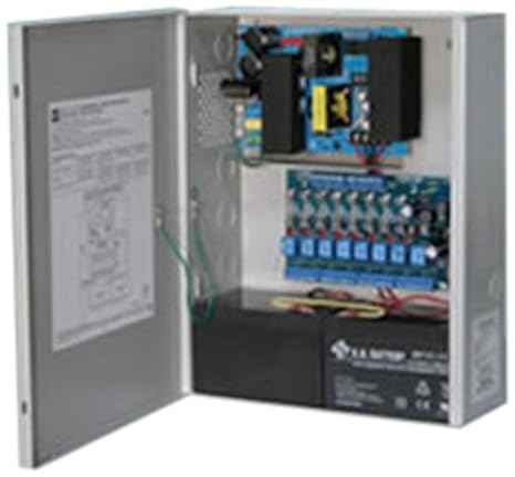
just one last note, this is how altronics safely makes low voltage dc supplies: https://images-na.ssl-images-amazon.com/images/I/41bisbg8xxL._SX466_.jpg
youll need an enclosure even safer to do 220
nimble terrace
ok ty yeah i ll ask about the enclosure, if they dont point that out
i want fix that for years
river venture
alrighty, well if you do plug it in make sure you use one of these at least while testing: https://www.homedepot.com/p/Tower-Manufacturing-Corporation-2-ft-In-Line-GFCI-Triple-Tap-Cord-Automatic-Reset-30438024/202510257
nimble terrace
I prefer safe environement
river venture
its better than a breaker, these really save lives
nimble terrace
acces denied
river venture
oh
nimble terrace
noticed last week too, idk why they dont want my ip
river venture
maybe the amazon page will show
im sure there is something similar for your mains power type
 quartz smelt
220 is not a normal 3 prong plug
river venture
yeah i know he is also in the eu
so he needs one built for his specific region
the important thing is that whatever he gets is gfci
nimble terrace
ok i note that
quartz smelt
yea, I was just thinking he was using normal 110 but pushing 220. Imagine the surprise when you plug in the blender
river venture
lol
quartz smelt
I wish some Hazzah32 users were on
 sly raptor
Crickit does not respond: I unwrapped a new Circuit Playground and a new Crickit and bolted them together. I used MakeCode last night to write a program to control a servo and a DC motor. It worked on the simulator, except there was was no simulated servo or DC motor. At the end of the cycle, it stopped until I clicked on the capacitive Touch pin. Great. But when I put together the real system, Neither motor activates. To start another round, it requires a capacitive Touch. The lights trace the behavior; the left lights change color with the step, and the right lights are a “progress bar” for each step. They all worked on the simulator. The lights all work perfectly. But motors and touch on the CP/Ckt do nothing. The servo does not move. The DC motor does not turn on. When it completes a cycle, touching a capacitive sensor does nothing. I have a demo in less than 48 hours and it would have been nice to have this.
I used MakeCode to write a servo test. Forever {90 deg, R1, wait, 0 deg, Y2, wait, 90 deg, G3, wait, 180 deg, B4, wait}. The end of the sequence state is shown in the third photo. But there is no servo action. Tried two different servos, no luck. I will be trying other tests. Here’s a photo including the servo connection. Nothing in my code produces the light pattern shown here, BBRBRBBBB. It happens after some number of iterations, I just counted 18 successful cycles. It died halfway through the 19th iteration. I have also posted this question in the Adafruit CP/Ckt forum. I didn’t show all of the loop because it is just 8 notes playing a little jingle.
 radiant valley
https://pastebin.com/nx02egmp
thanks @leaden walrus and @north stream

Pastebin
this is the code i made with your help
still a kitty coder but im working my way up😁
 torn frigate
@nimble terrace can you share how you made the graphs?
any ideas why this did not repeat every 2 hours?
left it for 6 hours now and only played it once
 honest nimbus
Probably because an unsigned long int count of milliseconds overflows at 30 minutes
Welcome to a computer science problem!
The laziest way to fix this is to delay for 30 minutes six times. The actual overflow is at around 32 minutes IIRC
@torn frigate
Wait no, I'm thinking of a smaller data type...
This shouldn't overflow until ~50 days have passed so this should be fine
Sanity check: Does it work with a smaller amount of time, like 1 minute?
Here's another computer sciencey problem: You're having the function call itself
Even if it worked, it would eventually crash the Arduino because it would fill up the address return stack
Take out the recursion call to doDiscord(); and just call the function within loop()
torn frigate
yea it worked with 5000 delay
so if i put it in void loop(){
it would be able to handle it?
honest nimbus
I'm not sure if it would fix your immediate problem, but it would fix an exciting future problem
torn frigate
😨
honest nimbus
I have an idea, but I'm spitballing because I don't know what board you're using and I don't know how the Discord library works...
Within loop(), instead of doing a delay, keep track of the time with millis(). It may be that delaying the code for that long causes the Discord servers to think your hardware has gone offline.
This example shows the principle: https://www.arduino.cc/en/tutorial/BlinkWithoutDelay
This way of doing a time delay doesn't block other code from running while it's waiting
 tiny marsh
anyone know how i can flash my m0 trinket back to arduino? is there is uf2 to drop in the bootloader?
 inland crag
I think you can just upload an arduino sketch to it
the arduino compatibility is baked into the bootloader I guess you could say
via the BOSSA compatibility it provides
 oak current
hey, is anyone good with midi for the arduino?
im trying to convert this toy piano I have into a midi device for use in a DAW
i have the key matrix mapped out, but i cant seem to map any midi commands to it
?
 merry stratus
I'm having some trouble with a memory leak I can't track down. every time I instantiate and destroy a Menu object I lose 24 bytes. adding more MenuOptions doesn't affect the size of the leak so it seems to be in Menu itself, but I can't seem to figure out what I'm missing. can anyone take a look? https://pastebin.com/04bzZe0R
nimble terrace
@torn frigate yes i can share, it a Javascript library called d3.js, https://bl.ocks.org/gordlea/27370d1eea8464b04538e6d8ced39e89
https://github.com/antoinebeland/d3-simple-gauge
Gord Lea’s Block 27370d1eea8464b04538e6d8ced39e89

GitHub
A simple gauge written with D3.js. Contribute to antoinebeland/d3-simple-gauge development by creating an account on GitHub.
My ESP logs data on card every minutes , and also it is a webserver. This websever/csv is called and displayed by another html/javascript page
 iron stirrup
on a single arduino uno, can I feasibly receive 5 sensor inputs with 3 outputs that turn on/off components?
 wide lark
@iron stirrup it really just depends on what your requirements are: how many pins does each sensor need for I/O, how much CPU power do you need to keep up with the processing of their data the way you want, etc.
the Uno has 14 GPIOs, which is quite a bit, so in that regard you should be ok
iron stirrup
5 sensors that detect if liquid level in a container is above or below a certain point (each sensor monitoring a different container) that sends a single output, then 2 outputs that each actuate a solenoid valve and 1 output that actuates a servo motor
wide lark
@iron stirrup gotcha, so I'm guessing your 5 liquid level sensors output an analog signal? you're in luck: the Uno has six analog inputs pins! then you have all 14 of those GPIOs for your outputs. so yeah, I think you'll be good
iron stirrup
https://www.amazon.com/DFROBOT-Gravity-Photoelectric-Overflow-Horizontal/dp/B07BQL7H9R/ref=sr_1_1?keywords=gravity+liquid+level+sensor&qid=1550862598&s=gateway&sr=8-1 its this thing. not exactly sure if its analog or digital or what
its pretty binary. either the liquid is at the level, or it isnt
my other concern is with outputs. I'll need 3 outputs that act as the switch on relays that then bring in higher-voltage power to activate solenoids, servos, etc
afaik, arduino only has one 5V output pin
 north stream
Looks like that DFRobot sensor provides a digital output, so can be used with any pin.
You could use a bipolar transistor or MOSFET to drive the solenoids directly. You'd probably need a transistor to turn on a relay if you want to switch things that way. The Arduino can drive a servo directly.
The 5V output is just a power supply output, it can be connected to several things if they don't draw too much power, otherwise you'll want to supply power to your other things in another fashion.
iron stirrup
the issue is that my two solenoid valves need 12V of power and my servo will probably need like 6V, whereas the Arduino power is just 5V.
related question - the GND/VCC/JD-VCC area is what powers the coils that flip the switches inside the relay, while VCC/GND around the two inputs gives the main power that will go out of the high power side, right?
so say I had a 2-relay board that was meant to output 12V to my two solenoids from the high power side (no/com/nc). I would give 12V to the top VCC/GND, and give some other kind of power to the lower GND/VCC/JDVCC in to power the coils to flip the switches?
north stream
Normally you'd keep the 12V stuff on the output side (to the left) not the logic side (to the right, where the VCC pins are).
For example, you could have 12 V supply to the NO contact, COM to the solenoid, then the other end of the solenoid to the 12V return.
The servo may be able to run from the same 5V supply as the Arduino, or it could have its own 5-6V supply. However, the logic signal that controls it could come from an Arduino PWM pin.
iron stirrup
wait. so power supply would come through a wire into NO, go into the solenoid by coming out of COM, then the circuit would complete by going into NC?
okay let me consider my actual use case thing for a sec
north stream
It's a two position switch: when the coil is not activated, NC is connected to COM and NO is not. When the coil is activated, NC is not connected and NO is connected to COM.
NC means "normally closed" and NO means "normally open". COM means "common".
For your use case, you can probably ignore the NC contact and just use the COM and NO contacts as a switch to complete the circuit through your solenoid.
So power source -> NO -> COM -> solenoid -> power return to complete the circuit.
 tardy vapor
can anyone tell me what are those things?
the blue box is a DHT11 temperature/humidity sensor
but what are the other two?
iron stirrup
@north stream is there a way I can somehow power both of my solenoids from the same power source?
north stream
Sure, as long as the power supply has sufficient capacity to run both of them.
The black component could be a capacitor (if so, "103" would give it a value of 1nF), but black components are often something else, like thermistors, tranzorbs, etc.
The blue cylindrical one could be a capacitor or inductor or perhaps something more exotic like a precision resistor, reed switch, etc. Does it have any markings?
iron stirrup
So if I have 2 12V solenoid valves and a 6V servo, would I use a 30V power supply and wire each relay channel in parallel?
 steep igloo
Hey, I'm wondering if it's possible to reprogram the Atmega8A in a USBASP to run custom code?
 shell lynx
Anyone have a good templated linked list header for Arduino? I've generally just hand rolled them when I've needed them but did a little digging today. The first two I found either had bugs or issues releasing memory. I came across some alternative free/delete implementations but haven't tried them yet. I know it's good to try to stay off the heap in uC's but have been playing with a D51 and would like to be able to keep some structures on the heap.
oak current
hey, is anyone good with midi for the arduino?
im trying to convert this toy piano I have into a midi device for use in a DAW
i have the key matrix mapped out, but i cant seem to map any midi commands to it
 bleak glacier
@tiny marsh Go through the guide to see how to get your Trinket M0 back to arduino https://learn.adafruit.com/adafruit-trinket-m0-circuitpython-arduino/uf2-bootloader-details Good luck.

CircuitPython or Arduino IDE on this tiny little microcontroller board
@oak current If you know that a key is pressed, you should be able to code the midi control codes to send. What are you having difficulty with?
quartz smelt
Whats this trying to tell me
Sketch uses 650862 bytes (49%) of program storage space. Maximum is 1310720 bytes.
Global variables use 37040 bytes (11%) of dynamic memory, leaving 290640 bytes for local variables. Maximum is 327680 bytes.
esptool.py v2.6-beta1
Serial port COM4
Connecting....
A fatal error occurred: Timed out waiting for packet header
A fatal error occurred: Timed out waiting for packet header
quartz smelt
Is there a Hazzah and a Hazzah32?
quartz smelt
Well it says Hazzah esp8266
merry stratus
I have a 16ch i2c PWM breakout board based on the PCA9865, I've hooked an LED to one of the channels just as a test, and it seems to dim fine, but strangely any time there is any other traffic on the i2c bus the led intensity spikes for a moment. I've tried with 2 different sensors and an oled display, any interaction with any of the other devices seems to cause it. why would this happen?
 rain horizon
i have a very simple programming question
can someone explain the statements within the first if statement
inland crag
it's a toggler
If you press the button and it used to be off, turn it on. If you press the button and it used to be on, turn it off
rain horizon
Then it changes everything to false. It's infinite. Always gonna be false. If it's not false, It changes to true, Which changes to false
inland crag
it's not infinite because it only happens when the button is pressed
inland crag
yeah I think it makes sense
merry stratus
if (buttonState == HIGH) {
on = !on;
}
a lot easier on the eyes
accomplishes the same thing
inland crag
true
rain horizon
What’s !
inland crag
nope
if it's false, not false is true
maybe you shouldn't call it on
it's confusing
rain horizon
So !on = on
merry stratus
no
merry stratus
👍
iron stirrup
so I wanna make a turntable that will have 4 cups of water 90 degrees away from each other. Need to be able to rotate each cup to another 90 degree position. Should I do this with a servo? stepper? what?
should go slowly and complete a 90 degree turn every like, 5 seconds
so 20 second full rotation
 eager jewel
I would use a stepper since you know exactly how much you want to turn it.
rain horizon
^
iron stirrup
the stepper turning the table from the center, or more like turning a gear that turns the table? the total weight of water and container should be in the ballpark of 8 pounds or so
max, that is
rain horizon
i say turning a table is more stable
eager jewel
I would probably have it turn the table so the weight of the table isn't too much for the motor.
I mean the geared method
iron stirrup
so now I gotta design a table with central rotation driven by a gear lol.
eager jewel
Maybe you could make use of a lazy susan?
iron stirrup
isnt there some more complicated wiring for stepper motors as opposed to a servo?
eager jewel
Yeah, but neither is super complicated. I think arduino has a good sketch that turns a stepper motor.
rain horizon
may i ask, why are you turning water cups?
iron stirrup
the turntable will be holding cups that hold solutions of proteins that once removed from the turntable will be put through a spectrophotometer for analysis
eager jewel
You may need to get a stepper motor driver such as an A4988
iron stirrup
cups are filled with proteins
eager jewel
Nice
iron stirrup
Behold my beautiful handmade diagram of my idea so far.
Solenoid 1 controls flow of protein solution into a cylinder, solenoid 2 controls flow out of cylinder into destination containers
eager jewel
Nice diagram. What did you mean by not sure what to do here?
iron stirrup
since I'll already be using my 5V power from my nano to operate the solenoids, for doing the stepper motor wiring/using the A4988, will I just use a different 5V power source and use the arduino for outputs only?
to answer your question, idk if those two should be jumped together, if they should have different power connected, what they're actually for, etc
eager jewel
Yeah, it should be enough depending on how you are powering the nano.
iron stirrup
what should be enough exactly? I'll be powering it via USB from a raspberry pi
eager jewel
I used a similar 8-relay module controlled by a Wemos Mini D1. I removed the jumper and just connected the 5V input off the USB to the JD-VCC input. It works great.
I had to replace the relay board after the first one had a faulty relay, but it's been working great ever since.
I made a youtube video about the replacement of the board at https://youtu.be/PDQ7w3dYMjM
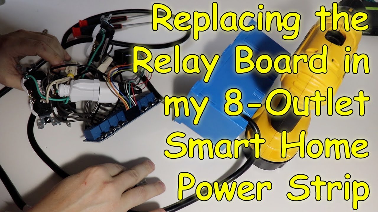
In this video I disassemble and replace the relay board in my custom built 8-outlet Smart Home Power Box. It is modular in design, so other than tinning the ...
iron stirrup
I just tend to want to isolate things because of my experiences in HVAC wiring and $20k rooftop units going boom
eager jewel
Then probably better to err on the side of caution and remove the jumper.
iron stirrup
so once that jumper is removed, how do I get a new 5V power source hooked in?
eager jewel
You would connect one to either of the VCC pins, which powers the logic of the circuit and another to the JD-VCC which is only for powering the relay coils. The ground is shared between them.
All the jumper does is it ties the JD-VCC and VCC portions together.
iron stirrup
Something like this?
eager jewel
I just took a closer look at your diagram and realized the 5V in a square represents a separate power supply. Yes, that looks correct.
I'm going to get going to bed now. Have a good night.
iron stirrup
sleep tight my dude
 deep kiln
Hello, I am new to this stuff. Can you guys help me by taking a look at my circuit if everything is wired correctly? It would be very much apprechiated.
deep kiln
S2 is wrong and supposed to go to another IO pin.
north stream
Looks reasonable, if confusing. Switches go from IO pins to ground, analog outputs to to analog inputs.
deep kiln
okay thanks alot
merry stratus
Does anyone have an i2c PCA9865 breakout and willing to try an experiment? 😛 I've been fighting with this for almost 24 hours now and making no progress. I can only assume the boards are somehow faulty, would love to just see the same circuit working correctly so I know i'm not crazy 😛
north stream
I don't have one, but there are a few things you might try (I don't know what you've tried already).
merry stratus
@north stream I've tried different pullup resistors ont he i2c bus, as well as 3 different "other" i2c devices that all seem to interfere. I've tried running hte code on an Uno and on an ESP8266 w/ 3v3 logic. the results are always identical.
i've also tried a second PAC9865 breakout (came in a 2pack) it has the exact same behaviour.
north stream
Have you run an I2C scan?
merry stratus
also changed its address from 40 to 41
no, i haven't done that. not sure what that is 😃
north stream
It's a simple sketch that tries every possible I2C address and reports what answers. https://playground.arduino.cc/Main/I2cScanner
It's one of the first things I try when I have an I2C device that's not answering.
merry stratus
ok, i'll give it a run, but my devices all respond fine. this one just seems to receive some kind of interference from any/every other device on the bus
north stream
Hmm, what is the failure mode?
Note that it requires TWO power connections, a 3.3V input to Vcc to operate the chip, and a 5V input to V+ to run the servos.
merry stratus
I was under the impression the V+ was optional and only for servos. I'm driving LEDs, I posted a video about 12h ago in here of the behaviour I'm seeing, basically my LED's flash whenever I talk to anything on the i2c bus
the video above is me polling a sensor every second while the PCA dims the LED in / out slowly.
you can see it flash every second
I posted on the adafruit forums here: https://forums.adafruit.com/viewtopic.php?f=19&t=148007 and the moderator seems to confirm that my led wiring is fine.
north stream
Ah, that's a different kettle of fish. You're able to talk to it, it just glitches its outputs when there's I2C activity?
north stream
I'm not 100% sure "any activity at all" is accurate. I wonder if the sensor driver is resetting the I2C bus.
merry stratus
if it is, then so is the oled driver, and the other sensor driver too.
i've run them all independently
they all interfere
fwiw the i2c scanner doens't show anything unexpected. 3 devices at the addresses I expect them to be
north stream
Yeah, I suggested the I2C scanner because I didn't know what the failure mode was and guessed (wrongly) that you weren't able to talk to it at all.
merry stratus
my only explanation, though it seems very unlikely to me, is that this is just a problem with this particular board I purchased, it's not the official adafruit one, though it uses the same library and seems to be of reasonable build quality. it also came as a 2-pack and they both display the exact same behaviour. I ordered the official but it's gonna take forever to arrive and Im expected to be sorely disappointed when it behaves the same way
north stream
How are the LEDs wired? From output to +V, output to VCC, or output to ground?
merry stratus
nothing is using V+ (not connected) the LEDS are just running from PWM->GND on each channel of the breakout. (with a 220Ohm resistor in series)
north stream
Hmmm. My only guess is that these are cheap Chinese boards with fake PCA9685 chips that are really microcontrollers programmed to emulate the real thing, except they get an interrupt on I2C communication and pause the PWM while servicing it.
merry stratus
that would be good news, and pretty awesome 😃
it just seems so unlikely to me.. lol
north stream
Since you can get an OTP microcontroller for 3 cents apiece, it's popular to use them to save money. Better yet, those particular microcontrollers are marked on the underside, so you can laser engrave a fake part number on top.
merry stratus
well if that's the case there is going to be a scathing amazon review of this board 😛
north stream
What I'd do is write a sketch that sets the LED to a medium brightness, then generates various waveforms on the SCL and SDA lines and watch the effect on the LED. I'm guessing that SDA is ignored, but every time SCL is driven low, the LED will flicker. That would imply that it is a microcontroller that is set up with an interrupt on the IO pin connected to SCL so it can catch those transitions to emulate an I2C slave.
There are a lot of reasons I do not buy from amazon. That is one of them.
merry stratus
I knew it was a risk but the canadian adafruit distributor I usually order from didn't have them in stock and it was going to take a while, I hoped these would function well enough to get the project started int he mean time
north stream
You could try eyeballing the board carefully too: the AdaFruit board takes care to wire various optional pins (like "output enable" and "external clock") to known values. If this board doesn't, it could also cause glitching.
merry stratus
I can't see much on the board, and not sure I'd know what I was looking for exactly 😃 the software experiment sounds more up my alley
north stream
It's getting harder to find useful stuff locally. When I want AdaFruit parts in a hurry, I usually buy them from Digikey and pay for fast shipping.
If I want AdaFruit parts today, I drive the hour and a half out to MicroCenter.
But if you're up in the Territories, useful outlets are going to be thin on the ground.
merry stratus
must be nice! Digikey is fast, but i try to avoid them unless i'm in the mood for a surprise brokerage fee. There's definitely nothing within a 4 hour drive either 😃
elmwood electronics is fantastic for a candian distributor
but if they don't have it in stock i have to wait for them to order it and the whole ordeal takes about 2 weeks
can you offer any advice on 'generates various waveforms on the SCL and SDA lines'? I assume i'll have to use the Wire library directly to do something at that level?
north stream
The Wire library doesn't give you low-level control, so you'll need to toggle the pins directly. Since I2C is an open-collector bus, you'll have to use the I/O pins in a slightly unusual manner as well, as you can safely pull them down, but you aren't allowed to pull them up.
So a simple test to pulse the SCK lead might look like ```c
pinMode(SCK_PIN, OUTPUT);
digitalWrite(SCK_PIN, LOW);
delay(100);
pinMode(SCK_PIN, INPUT);
ok I'll give it a shot
I should still use the adafruit pWM Driver lib intially set the LED though right? then switch the pin modes after the LED is on?
#include <Arduino.h>
#include <Wire.h>
#include <Adafruit_PWMServoDriver.h>

Adafruit_PWMServoDriver pwm = Adafruit_PWMServoDriver();

void setup()
{
  pwm.begin();
  pwm.setPin(0, 1024);
}


void loop()
{
  pinMode(PIN_WIRE_SCL, OUTPUT);
  digitalWrite(PIN_WIRE_SCL, LOW);
  delay(100);
  pinMode(PIN_WIRE_SCL, INPUT);
}
I dont see any flickering with this code
actually, I see one brief flicker about 1 second after it starts up.
strange
i think its just the arduino resetting, nevermind.
seems stable
tried the same thing to SDA and it behaves fine.
north stream
Ah, that's useful information (if not quite what I was expecting).
Try adding a delay(100) as the last line in loop() so it spends some time in each state.
merry stratus
still good
north stream
void
loop()
{
  int pulsetime;

  digitalWrite(PIN_WIRE_SCL, LOW);
  digitalWrite(PIN_WIRE_SDA, LOW);

  for (pulsetime = 100; pulsetime < 20000; pulsetime += 100) {
    // turn on SCL
    pinMode(PIN_WIRE_SCL, OUTPUT);
    delay(pulsetime);
    // turn on SDA
    pinMode(PIN_WIRE_SDA, OUTPUT);
    delay(pulsetime);
    // turn off SCL
    pinMode(PIN_WIRE_SCL, INPUT);
    delay(pulsetime);
    // turn off SDA
    pinMode(PIN_WIRE_SDA, INPUT);
    delay(pulsetime);
  }
}
That should iterate through a variety of pulsewidths and combinations.
merry stratus
nada. perfectly stable LED.
this is getting wierd
maybe it's only happening when another device replies on the i2c bus?
not sure how much of a difference that could make
north stream
That would be odd, as devices replying is the same thing (they drive SDA low).
 daring marsh
andre what are the other devices?
merry stratus
TSL2591, Si7021, and a SSD1306 OLED
each of them independently connected causes the exact same issue
daring marsh
post a clear photo of your wiring
merry stratus
sure, give me a moment to clean it up a little 😃 been experimenting for hours
I will build the absolute bare minimum reproducible
daring marsh
its somethingwith your wiring
most likely
i2c devices dont' conflict each other if they're on other addresses
merry stratus
yeah that's why I bought it, was hoping for something that would be reliable and stable 😃
daring marsh
dont mess with the SDA/SCL pins tho -
did you buy anytihing from adafruit?
if the boards are from amazon, ask the seller for their support forums - they should have engineers they've hired to help you!
gotta 🌮 l8r!
merry stratus
not easy to photograph lol
FWIW: The 2 sensors are from adafruit, the PWM Driver is a clone, but the seller was not helpful (said its an i2c conflict)
in the photo i'm using the 2nd power rail from the top as the i2c bus.
the 2 resistors ont he right are 4.7ks pulling SDA and SCL up to 5v
220Ohm on the LED
north stream
Those wires are a little long for I2C.
merry stratus
maybe a little but even with all 4 devices connected with wires that long, there ar eno communication issues anywhere
i2c should support at least a meter no?
uh-oh... i can't get it to flash anymore 😐
quartz smelt
Success after a week
66666666666663
WiFi connected
IP address:
10.0.0.135
connecting to wifitest.adafruit.com
Requesting URL: /testwifi/index.html
HTTP/1.1 200 OK
Server: nginx/1.10.3 (Ubuntu)
Date: Sat, 23 Feb 2019 16:39:59 GMT
Content-Type: text/html
Content-Length: 73
Last-Modified: Thu, 16 Feb 2017 17:42:29 GMT
Connection: close
ETag: "58a5e485-49"
Accept-Ranges: bytes
nimble terrace
random port order on ESP is an ultra bad design, so much time lost finding wich pin is what !
also as a noob i m lost with all those port flavors, where I find what are they used for ?
deep kiln
Another maybe stupid question. What are the unlabeled pins in the middle for?
between the ground and 3,3v pins
 tough snow
@deep kiln That's a prototyping area. The pins aren't connected to anything. You can add things like, say, a DHT11 temperature sensor, a button, or something like that and solder it to the board, and then use hookup wire to connect it to the correct pins
deep kiln
ah ok thanks 👍
tough snow
@nimble terrace I doubt it's truly bad design. The ESP (both 8266 and 32) modules have them laid out in specific ways. Both are small boards, so there's only so much room to route them from the chip. This is carried over into the boards they are attached to, and similar design constraints follow. On a feather-sized board, it can be similarly impractical to route connections in a "sensible" way, especially if you want to keep the PCB 2 layers.
Something like that Arduino Uno (Or Adafruit's Metro series) has a much larger footprint, and you can route things in interesting ways to get them to the desired area
nimble terrace
But why not label the pin in a physical order ?
tough snow
They typically are labeled following how it's determined with the chip itself. Which... is a complex thing that I can only really speculate at
nimble terrace
Ok i see, yeah would be a beginner io label 😃
my pinout document legend was missing, I added it, it is a bit clearer now
tough snow
With all this said, though, I do find it annoying when two 'consecutive' pins aren't near each other
So while I understand why, it doesn't make it less annoying to work with
nimble terrace
this does not ease the wiring process
I will have a look at the espressif datasheet
tough snow
I'd recommend that. What's the project?
 narrow thorn
if you have a cpx and want to use adruino ide.. should your include be #include <Adafruit_CircuitPlayground.h> or is there one for the express?
nimble terrace
sensors , sdcard, webserver, are all ok, I'm adding relais. Most thing works when I found the right pin and there is no false contact, and that not that easy ....
tough snow
@narrow thorn Given the hardware difference between the CircuitPlayground classic and CPX, I'm leaning towards there being separate ones. But I haven't used either on Arduino, so haven't looked into it.
narrow thorn
It is really difficult finding examples for ardino for cpx
tough snow
It's definitely aimed for CircuitPython
@narrow thorn Take a look here: https://learn.adafruit.com/adafruit-circuit-playground-express/arduino
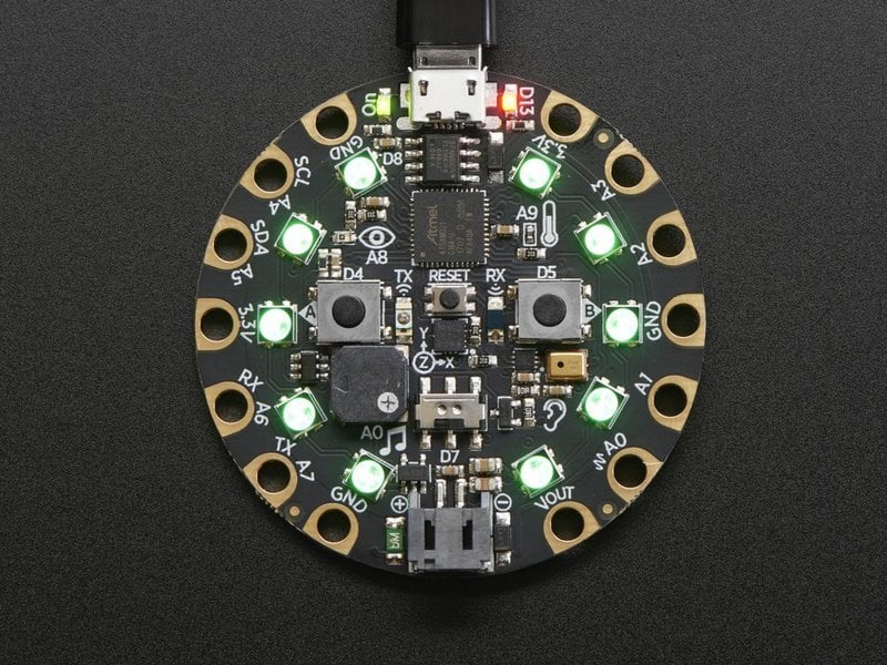
Make faster and easier than ever with MakeCode, code.org CSD, CircuitPython or Arduino!
narrow thorn
I found a cool one for some led and buttons action.. a wearable led thingy.. but it is for cpc and has an extra led strip.. I have one function working on the cpx.. but everything else does nothing, which makes me believe that there must be a difference
tough snow
Looks like I was wrong. It's just Adafruit_CircuitPlayground.h
narrow thorn
hmmm
this is what I am trying to play with https://learn.adafruit.com/sparkle-skirt-playground/make-the-light-strands

Lights, Sound and Motion for Your Ensemble
 weary ember
So um.. is there a channel for very very basic noob questions?
 wet crystal
wet crystal
wet crystal
Sry for that kind of bad joke
weary ember
I'm just trying to learn how to use shift registers, and I don't think arduino.cc's example codes are working right for me
wet crystal
You can do it by yourself
wide lark
@weary ember do you know python?
wet crystal
Or use 74hc libary
wet crystal
The Shift Register 74HC595 Arduino Library makes the use of shift registers much easier. This is the official download and documentation page with explanations, schematics, examples and a lot more.
That´s the most easy way i think
weary ember
Hm.. well both of the sketches in question are still being weird
meh, i'll figure it out
Thanks anyway! 😃
weary ember
Okay I have a more specific question..
if I set variable
byte a = 0;
then
bitWrite(a, 2, 1);
Now byte a should = 4 right?
am i understanding this wrong?
weary ember
okay thank you rpj, in that case I cannot understand why this code isn't working
weary ember
Its not even my code, its from arduino.cc, 1 moment
maybe its an issue with my serial input actually
wide lark
yeah, you might want to debug how you're using the code, because at a quick glance it looks correct
weary ember
okay, I will do that later, thank you for the assist
wide lark
sure thing! best of luck, let us know how it goes
weary ember
my serial monitor was set to "newline" which apparently breaks this sketch lol. oh well at least I learned some new stuff.
nimble terrace
On Arduino Uno Relay Ligth and click and works OK, on ESP32, same code, same Relay just Light but no click, and does not work, What am I doing wrong ?
I use 5v as VCC on the ESP, should i go 3.3v ?
rain horizon
for some reason, when i click the button, it doesnt work half of the time. I click it, and nothing happens, and then i click it again and it works fine. sometimes i can even click it 4 times in a row and the light wont turn off and then the next 4 times it will work perfectly fine.
is this an issue with my program or my wiring
theres my program for reference
nimble terrace
looks ok, but overcoded
You can just write digitalWrite(ledPin,!ButtonState);
check your wires and the button connctivity with a multimeter
if it is a 4 pins button it may not work the way you think, I got tricked too 😃
nimble terrace
Got it to work, esp controlling the relay, Uno powering it. the ESP 5v is not enough
nimble terrace
north stream
Yeah, as written, that code will turn the LED on and off rapidly and stop at whatever state it happens to be in when the button is released.
rain horizon
digitalWrite(ledPin,!ButtonState); makes the button behave like a button
when i let go, it just turns off
i need it to stay on
digitalWrite(ledPin,!on); makes it into a switch, but its having the same problem again
this seems to work great
works every time
inland crag
that second if statement doesn't make any sense
that's an assignment not a boolean
if (buttonState == HIGH) {
    on = !on;
    delay(500);
}
digitalWrite(ledPin, on);
do that
 hasty pecan
Hello
I'm new to this
and i have an adafruit circuit playground
its a class assignment
i want to make this
ill screenshot
I wanna make a touch sensor connected
to adafruit on the glove
so whenever someone shakes my hand it'll light up
how would i make this work?
honest nimbus
Many of the Circuit Playground's pads can already be set up as touch sensors, so you'd just need to run a wire to where you wanted to do the sensing
hasty pecan
Hmm
how would that work
Like i'm using conductive thread
would that also work
also i get to try out with alligator clips
honest nimbus
Tie the thread to one of the input lines on the CPX, and then your sensor would be maybe a small square of aluminum foil
you can either tape the thread down to the foil (try fraying it a bit on the end) or use the alligator clip
hasty pecan
Hmmmm
I'll show u all of my supplies
because i dont know if im allowed to use that
Btw i really appreciate your help
thanks man
honest nimbus
Sure :)
hasty pecan
Thanks 😄
honest nimbus
The Circuit Playground also has an accelerometer. You could try detecting a "handshake" motion as well
If you used both that and a touch sensor, you could tell the difference between holding hands, shaking hands, and a high-five
hasty pecan
Create a new survey on your own or with others at the same time. Choose from a variety of survey types and analyze results in Google Forms. Free from Google.
Ohh
Thankss
how does an accelerometer works
I heard i can use that
honest nimbus
First, here's a tutorial on CPX's capacitive touch capability https://learn.adafruit.com/circuit-playground-fruit-drums/hello-capacitive-touch

Make some block rockin' beats with Circuit Playground.
This will walk you through turning pretty much anything into a touch sensor
hasty pecan
Alright
Thanks
I'll ping you if i need any further help
Also, how would my code work?
honest nimbus
What language are you using, Python?
honest nimbus
Okay, here are the references for the CircuitPlayground Arduino library http://adafruit.github.io/Adafruit_CircuitPlayground/html/class_adafruit___circuit_playground.html
and for the accelerometer http://adafruit.github.io/Adafruit_CircuitPlayground/html/class_adafruit___c_play___l_i_s3_d_h.html
honest nimbus
Start with just the Circuitplayground library for now
honest nimbus
Ping please, so other people can help :)
hasty pecan
alright
honest nimbus
No, I couldn't view the sheet. It's private
hasty pecan
I'll screenshot it
honest nimbus
k
honest nimbus
The black woven conductive fabric will do the job of the tinfoil
Here's a tip: It will detect your hand just as well as someone else's, so you might want to attach it to the outside of a normal glove, rather than make a glove out of the conductive fabric
honest nimbus
👍
hasty pecan
so would i take a small square of conductive thread
i mean conductive fabric
then sew a conductive thread to it
that i connect to the adafruit circuit playground
honest nimbus
Yep
honest nimbus
What an accelerometer does is detect bumps. Think of it like a Wiimote controller from the original Wii
hasty pecan
ohhh
honest nimbus
It can detect when you swing it around and in what direction.
hasty pecan
so i just need a code
honest nimbus
yep
honest nimbus
That should be enough power
I don't think they'd give you an option that didn't work
honest nimbus
Discord can be weird like that
hasty pecan
yeah
lol
anyways so
ill find sample codes
and stuff
they're hard to find tho and ill try and figure out how arduino works
honest nimbus
Good luck!
hasty pecan
Thanks man
@honest nimbus#48
How would i make this code work
would i copy paste random codes
that i find
honest nimbus
That's not how you learn to program. That's not how you learn to write, is it? Copying and pasting random sentences?
What sort of lessons did your teacher give you on how to program in Arduino?
Here is a very similar project - "touch capacitive sensor, thing happens" https://learn.adafruit.com/circuit-playground-valentine/code-with-makecode

A Special Gift to Make Her Fall in Love with Making
But it's done in MakeCode. It's up to you to translate that to C++ for Arduino
honest nimbus
Well, ask her! If you've never programmed before, tell her, see what sort of help she can give you!
hasty pecan
Alright man
She said she would help me once we had a code to work with
she's a bad teacher anyways
honest nimbus
hm
 hardy parrot
Hi, do you guys know how to use the Arduino Official TFT Screen and the Adafruit Music Maker Shield at the same time on an Arduino. (I'm not talking about the stacking headers that I need to solder on top of the shield in order to get access to other pins.) I tried redefining the pins but it didn't work. Thanks and have wonderful day! Music maker: https://www.adafruit.com/product/1788 Arduino Official display: https://store.arduino.cc/usa/arduino-lcd-screen

Bend all audio files to your will with the Adafruit Music Maker shield for Arduino! This powerful shield features the VS1053, an encoding/decoding (codec) chip that can decode a wide variety ...
The Arduino TFT screen is a backlit LCD screen with headers. You can draw text, images, and shapes to the screen with the TFT library. There is an onb
honest nimbus
I'm still poking at it, but I'd bet the problem is that they're all trying to use the same device select pins for SPI
SPI can go to multiple devices, but each device needs one pin to tell it that it's being talked to.
@hardy parrot Hm, the hardware shouldn't be a problem - you can run the screen CS pin to Digital 5 and the Backlight pin to Digital 2 and ignore the TFT's SD card, and everything will "fit"
But software-wise, this might not work out, see this note from the Music Maker tutorial:
The MM chip (VS1053) wants to be fed data constantly so that it keeps the music playing. You can take small pauses to do stuff in between playing, and for real-time sensors like IR receivers, you'll have to not-use interrupt based playing and instead pause to read. See this thread for ideas```Running a screen is not "small pauses" processing for an Arduino
The tutorial doesn't have a link
despite saying it does
honest nimbus
Yep! Even if the software doesn't work out, wire it up and try to get it working "enough"
It might work, who knows! Especially if the screen has a buffer (I don't know) and doesn't require constant updates
If it does have a buffer, then it might skip the music while redrawing but that may still be good enough
hardy parrot
I'll try it today for sure
Thank you very much for your time and have a wonderful day! 😊
honest nimbus
You, too :)
torn frigate
Humidity: 20.50 %
Temperature: 20.50 °C
Humidity: 20.20 %
Temperature: 20.20 °C```I changed the DHT11 library and now the output is this ^
it just reports same values for both temp and humidity
code: https://paste.ee/p/ociX6
 north stream
I'm not that familiar with the library, but it looks like the sensor variable holds the humidity data and the event variable holds the temperature data, but you're trying to read both the temperature and humidity from the event variable?
merry stratus
@north stream I made a little more progress with my LED Driver interference issue this morning. thought this might be an interesting detail. if I set the LEDs to certain level and leave them, there is no "interference". it's only when I dim/brighten them in the loop that they start acting on all i2c traffic
north stream
Interesting. I'm sure that's a clue, but I don't know what it means. It's almost as if an I2C bus cycle was left unfinished, so traffic coming after it was accepted as more commands?
merry stratus
sounds reasonable. and at least that points to a single potential driver issue rather than every othe i2c device being broken somehow 😃
merry stratus
Oooh, even better, ONLY when using pwm.setPWM, pwm.setPin behaves correctly.
nimble terrace
Hey,
I struggle external powering a 4x relais on side of an esp32 :
The setup from doc fails, the relay does click click and stops, it is like :
esp = 3.3V on VCC + In1 / External = 5V on JDVCC + GND / JDVCC jumper OFF
But this setup actually works :
esp = 3.3V on VCC + In1 / External = GND / JDVCC jumper ON
Is that normal ?
without external power esp is too low to activate the relais, only the led light
also i derivated the external power form the same USB cable that power the ESP
weary ember
"shiftout_using_an_array.ino" contains unrecognized characters. If this code was created with an older version of Arduino, you may need to use Tools -> Fix Encoding & Reload to update the sketch to use UTF-8 encoding. If not, you may need to delete the bad characters to get rid of this warning.
Fix Encoding etc... does nothing, anyone know what the unrecognized char is?
merry stratus
merry stratus
np
nimble terrace
It works as it should if i separate esp power and relais external power, but not when external power is derivated on same usb cable that power esp, and idk why ;/
nimble terrace
I use a 2A use power
merry stratus
a phone charger?
nimble terrace
yes
merry stratus
afaik they can only deliver 500ma unless the device ont he other end actively requests more
the esp can't do that
nimble terrace
It works in one config, when the external is used for grou nd only
merry stratus
shrug i'm no expert that's for sure 😃 I only know that phone chargers are rarely sufficient to power a raspberry pi reliably, so it seems likely you're running into the same issue
I have a very nice 2.1A phone charger with a fat cable that consistently underpowers a raspberry pi.
nimble terrace
This should work external 5v on jdvcc
This work external provide only ground jumper is on
It is not like missing power, on the first setup the relays click clik like 3 times and stops, like if there was something bad
It looks my derivation sucks and put the relay in short circuit when both on same cable, if i separate powers, or if I setup like second picture it is OK.
merry stratus
wait, if the relay is powered with 5v, it probably can't properly interpret the 3v3 logic from the esp, no?
nimble terrace
the esp is on 5v too
but i think i rode this could work 3.3v + eternal 5v didnot try it out
merry stratus
esp32 is 3v3
it lowers usb voltage to 3v3 and uses that
if you use external 5v you probably need a level shifter between
merry stratus
yes, but it only does 3v logic, so the relay only receives a 3v signal
probably not enough to flip it
nimble terrace
the 5v of the esp are not enough, led light only
merry stratus
did you try powering the relay with 3v3?
nimble terrace
5v esp + 5v external, separated works as indicated in documentation (maybe 3.3 too). and i m trying to put them on the same usb cable
5v esp + external ground from same cable works, buut with jumper on
nop didnot try 3.3
merry stratus
worth a shot, otherwise I have no idea 😃
nimble terrace
ill try the current working config with ground only
thx btw !
it seems 2 works pretty good 2 with 2 relais, light are strong
wide lark
Does anyone know of any resources detailing exactly what C++ language features and subset are supported by the different Arduino platforms? I'm writing a library and want to use the STL but it looks like it's not supported everywhere (such as the more-limited older devices like the Uno), among other things. Would love to have a matrix of feature-sets so I can make an informed decision as to which platform(s) to target and which to exclude. Thanks!
quartz smelt
@daring marsh quick question? on the Hazzah sp8266 what pin would be the equivalent of pin 2 on an uno? i am ready using I2C 4,5 for temp,hum
quartz smelt
@daring marsh Thank you
torn frigate
what reset button does on boards?
north stream
Resets?
inland crag
It sets the reset line of the mcu, and it does whatever it's supposed to when that line is set
nimble terrace
ok thx
Hey, what connectors should i use to easily plug and unplug a 4+ wires cable on a PCB card ?
I m using dupont atm, but now I m looking for something stronger, maybe clicky
wide lark
@nimble terrace I have the same need pretty often so I have a bunch of JST connectors on-hand for exactly that: https://www.aliexpress.com/item/10Pcs-Cable-Connector-1-25-JST-Single-Electronic-Wire-Connectors-2-3-4-5-6-7/32870128111.html?spm=a2g0s.9042311.0.0.477a4c4d2xTgha

aliexpress.com
Smarter Shopping, Better Living! Aliexpress.com
in fact that AliExpress seller has all sorts of connectors: https://www.aliexpress.com/store/group/Pin-header-Housing-Terminal/1089753_500654268.html?spm=2114.10010108.100008.12.407f16f9iRojog
nimble terrace
ok thx, so JST is the standard
wide lark
I'm not sure if it's a "standard" per se but I have seen it on a lot of devices which is how I was first introduced to it
(I bought a couple of these but couldn't use them for months after they'd arrived while I tracked down the right-sized JST connector for them 😆 https://www.sensirion.com/en/environmental-sensors/particulate-matter-sensors-pm25/)
The SPS30 particulate matter (PM) sensor enables accurate measurements from the device’s first operation and throughout its lifetime of more than eight years.
I do know that Adafruit sells their batteries and PowerBoosts equipped with JST connectors, can't remember which size they use though
nimble terrace
haha yes so much references
wide lark
LOL so true!
nimble terrace
I may try Air quality monitoring one day, this will soon be a matter of survival
wide lark
yeah you don't have to tell me: I built my sensor because I live only miles from the Wine Country fires of '17, so it's already kinda become a matter of survival for us. my sensor systems use python exclusively (although are RPi-based, so not Circuit Python though definitely use lots of Adafruit code); here's more if you're interested: https://www.hackster.io/rpj/atmospheric-particulate-matter-environmental-sensing-fb31a1

Hackster.io
An air quality (particulate matter) and environmental (T/H/P) sensor system built with a Raspberry Pi Zero W, Python & Redis. By Ryan Joseph.
nimble terrace
nice thx
wide lark
You’re welcome, and best of luck finding what you’re looking for!
nimble terrace
thx for sharing your recipe, the result look great
wide lark
I appreciate that, thank you! I feel I could do a lot more to make it look better (and run better), but no project is ever actually “done” right? 😜
nimble terrace
where can I find good arduino code exemple ?
I need a datalogger, that handle CSV, has a timestamp, and run a command in non blocking loop. There are a lot of exemple on the web, but most are just begginers POC and not good code.
Is there some known well coded project or resource that can inspire me ?
 proven shoal
I'm using an Arduino DUE, and I'm trying to read 2 encoders which output both Quadrature and PWM. I'd like to read the PWM at first to get the absolute position, then switch to Quadrature for everything else. What I'm struggling with though is where to plug in the two PWM, as I'm already using TC0 and TC2 for Quadrature decoding.
https://content.vexrobotics.com/vexpro/pdf/SRX-Mag-Encoder-User-Guide.pdf (Here is the encoder btw)
north stream
I'm not sure what TC0 and TC2 are here. Timers?
proven shoal
uh, yeah.
I was looking into TC1, but I couldn't find the inputs in the pinout
Is there a better way to refer to them? lol
north stream
I don't think you need a timer to decode quatrature, just keep track of the edge order. Perhaps look at the PJRC quadrature library, it's pretty good.
proven shoal
I'll take a look at it, thanks
iron stirrup
quick question, what should I use for 5V external power supplies to give power to logic in my boards?
preferably such that they plug into the wall and I can mess with the wires
12V as well
Hopefully this helps clarify what im saying
 calm parcel
I have a drawer of power bricks of various voltages that I rummage through to find the right voltage and current capacity.
north stream
Phone chargers are easy to come by and great for powering various circuits.
I'm also fond of looking at thrift stores, they'll often have a bin of assorted plug-in power supplies of various voltage and power capability for low prices. I also grab any from anything I'm discarding.
wet crystal
At the workplace from my girlffriend they are throwing away psu
I just grab them from bin
Have really good Laptop Charger
Now to my question.
XD
I want to save data recorded with a wemos.
Since im broke this month, but had a USB Stick handy, I just plugged it into my router and set it up as a Inhome Storage. You can´t reach it from the internet atm.
I just asked myself, if it should be easy to write data to that stick with a wemos in the same network, without giving internetacces to this NAS.
north stream
If you're connecting the Wemos to your AP's internal network (like your other in-home machines), it should have the same access.
wet crystal
Do you have a link for a tutorial? Didn´t found some.
north stream
A tutorial to hook to your own AP?
wet crystal
As you think you know a video, that helps a beginner with my problem.
I just need to know, how to send data to that stick, since it is not opperating as a full nas
north stream
Depends on what your AP supports. Could be FTP, HTTP, AFS, NFS, or any one of quite a few other things. If you're really unlucky CIFS or SMB.
wet crystal
Für IP-basierten Anschluss, Geschwindigkeiten bis 1000 MBit/s, ideal für MagentaTV: Jetzt Speedport Smart 3 bestellen. Zwischen Kauf & Miete wählen.
I really dont know
north stream
A little looking around indicates that the Speedport Smart probably supports FTP access to a USB drive.
wet crystal
I remember. I saw that in a video, but when i looked for this option i didn´t found it
north stream
In any case, you'll probably want to configure everything with a computer before trying to attach to it with a microcontroller.
wet crystal
Yeah, that would be a pain in the a**
north stream
I did find this writeup explaining that there's working FTP client software for the ESP, but it links to an article that has been removed. https://stackoverflow.com/questions/53574185/how-to-write-data-to-a-text-file-then-send-to-ftp-server-on-arduino-esp32
iron stirrup
okay, another quick question
why use arduino/arduino clones over Raspberry Pi GPIO?
it seems I can do with a raspberry pi's GPIO everything I can do with an arduino uno/micro/nano
ease of code? what?
iron stirrup
makes sense. I'm more asking about functionality of one vs the other
school is paying for it so
dont have to worry all that much about budget
wet crystal

Best PCB prototyping ($2 for 10 boards): https://jlcpcb.com Previous video: https://youtu.be/b2sBhDxmPmA Arduino Basics 101: https://youtu.be/BtLwoNJ6klE Ard...
The benefits on both, depends on what you are about to do.
You dont buy a Ferari to go slowly you know
north stream
For tight timing, I'll opt for the Arduino class machines. For heavyweight processing, the Pi gets the nod.
iron stirrup
Define tight timing.
Also real quick, is this the proper way to wire a relay board with external logic power?
north stream
Tight timing, such as sending signals with a known, reliable timing.
I think you'll need to hook up Vcc (operates the control circuitry) as well as JD-Vcc (operates the relay coils). You'll need connect ground to the ground on the circuit driving the inputs.
You have the option of using a single 12V supply to run both loads, if your supply has enough capacity.
north stream
If you're driving it from a 5V board, yeah, do that. If you're driving it from a 3.3V board, hook 3.3V to Vcc and 5V to JD-Vcc.
Capacity is the amount of power a supply can deliver. If your solenoids take (say) 100mA apiece, and the supply is capable of 500mA, it can run both of them. On the other hand, if the solenoids take 400mA apiece, then a 500mA supply could only run one of them.
wet crystal
Well @north stream it seems like this model doens´t support FTP
north stream
Any idea what it does support?
wet crystal
I read st about smb
but im not sure
Well, I tried to setup a dns server
But you can´t reach it from outside
datenlog.ddnss.de give it a try
And if I try to log in, from my pc it says wrong user data
north stream
I don't get an address for that host (which is probably for the best).
north stream
SMB is a can of worms, as it's one of those "standards" that doesn't have any compliance specification as almost all of the features are "optional", so even a fully-conforming SMB client may not work with any given SMB host.
north stream
It probably has a default login, you'll have to look that up in the manual. Unless the default was changed, if you don't remember what it was changed to, you're likely stuck doing a factory reset.
iron stirrup
could I use the 5V from an arduino board to power multiple relays/drivers?
north stream
It'll tend to put noise on the line, and relays can be power hungry, so it would probably be fine for a small number of them.
iron stirrup
I'm planning on two 5V relays and a A4988 stepper motor driver
north stream
The relays should be fine. May want a separate supply for the stepper if it's bigger than the little air conditioner variety.
iron stirrup
Very rough schematic of what I'm saying
With the + and - lines as if a breadboard
Would it work? Operating those 3 things?
 trim bane
really beginner question, Vin is to power a board and VCC is power out?
honest nimbus
It depends on the board. Generally, VIN is the raw power in and VCC is the output of the voltage regulator
but you can also feed the correct power directly into VCC to power the Arduino, if you have a power supply somewhere else in your project
trim bane
ok thanks, sorry just trying to read some info and noone really explains that very well!
honest nimbus
No worries! Questions are what we're here for
inland crag
honest nimbus
@iron stirrup It's tought to say without knowing what's on the relay boards. Different boards have different supporting circuitry (e.g. a flyback diode, an indicator LED, a switching transistor or MOSFET with a base resistor)
Otherwise that looks good and fine
Assuming the relay board has a flyback diode and is one of those active-low types with a little MOSFET coil driver
iron stirrup
It's a sainsmart 5V relay board
honest nimbus
Yep, that has all the good protection stuff and you can hook it directly to the Arduino
iron stirrup
Hell yeah
I'm doing it with a usb-powered micro or nano most likely
Though I may try to implement my system using a pi only at some point
hasty pecan
so would i take a small square of conductive thread
i mean conductive fabric
then sew a conductive thread to it
that i connect to the adafruit circuit playground
And i have this accelerator thingy
im tryna find codes on how to make it work
I'm tryna make it so whenever i high five someone the conductive thread will detect it as a touch sensor
and the accelerator sends the signal to the adafruit circuit playground so the lights start lighting up like a rainbow or whatever
how would i make this code?? i tried using these code sample websites
oh yeah, and this code needs to be build for arduin
arduino
@honest nimbus oh help
MY SAVIOR HAS ARRIVED
nooo what happened to factory factory
oof
he's back
epic
honest nimbus
I can't find an all-in-one source, but here's a basic tutorial on C++. It starts with examples, breaks what they mean line-by-line, and then gives you little lessons and challenges on what the parts of C++ programs are and how to build them. https://www3.ntu.edu.sg/home/ehchua/programming/cpp/cp0_Introduction.html
honest nimbus
Once you have read that and started to grok it, here's Arduino's "foundations" page: https://www.arduino.cc/en/Tutorial/Foundations
honest nimbus
Okay...
hasty pecan
is there any already made code
honest nimbus
Okay, so here's what sucks
honest nimbus
For me or any number of other folks here, your project is like.... five minutes
honest nimbus
If you'd been taught how to do any of this, you'd have a few hours' worth of trying and failing ending in a learning experience and success
honest nimbus
Yeah most "learn to code" programs basically through you in the deep end, and then correct you bit by bit with whatever outrageously incorrect thing you came up with
hasty pecan
yeah lol
honest nimbus
While I'm looking things up, write some comments. Good commenting is very good programming habit and it's not wasted effort. Here's what you write:
You write what you want your program to accomplish
honest nimbus
// This is a single line comment.
/* This is a multi-line comment.
Comments are for people to read.
The computer ignores them. */
Right
honest nimbus
So something like
// High-five detector - touch sensor on glove to detect a high five
honest nimbus
//Touch sensor is attached to pin 2
No. But they describe what you are trying to do
Which helps you when you come back to it, and helps other people understand what you are trying to do
Really good, professional code spends more than half the time on comments, because professional code needs to be worked on by lots of different people.
// Use the built-in LEDs to light up
That kind of statement
honest nimbus
Okay, excellent. You have the Circuit Playground library installed in the Arduino software, I'm betting
If so, then you can go to File --> Examples --> Adafruit Circuit Playground
And there are a whole bunch of pre-made programs that will do things and work already
honest nimbus
Yes
hasty pecan
hol up ill get back to you
honest nimbus
It'd be near the bottom, "Examples from custom libraries"
hasty pecan
Alright thanks
honest nimbus
check out the AccelTap example
You know how I was saying an accelerometer can be used to detect a "bump"?
That demo does exactly that
Right now, all it does is print to the serial console
honest nimbus
However, if you go to Hello_CircuitPlayground --> Hello_Neopixels, there is code in there to light up the pixels
honest nimbus
No. That is still something you would have to try yourself
Serial console (tools -> Serial Monitor) is a simple text data exchange between the CP and your computer
honest nimbus
Here, just gonna give you this one. From the CP examples, the demo program gives this handy function:
CircuitPlayground.readCap(n);
That will read pin n as a capacitive touch sensor
honest nimbus
Just one pad at a time
honest nimbus
yes
so, your comments would look like
void loop () {
    // Check pad for touch
    if (CircuitPlayground.readCap(<some pin>) == true) {
        // Light the LEDs for two seconds
    }
}```Oh ok
honest nimbus
I feel like if I give you any more code or even pseudocode, I would be doing the assignment for you :(
hasty pecan
@honest nimbus its between you and me
(:
lawl
@honest nimbus oof im confused again
honest nimbus
That's normal
honest nimbus
the CircuitPlayground library isn't installed?
hasty pecan
lemme show you
noo
i tried to find it but i went to the arduino library
this is my code rn oof
honest nimbus
Go to Sketch --> Include Library
honest nimbus
Under that, Examples
honest nimbus
Never mind. Go to Libraries
honest nimbus
I don't think it's there. I am.... befuddled
honest nimbus
I am trying to figure this out but the website is doing crazy things to me
okay that's good
honest nimbus
well, that's good
because I don't see any way yet to get the CircuitPlayground libraries on the web version
Apparently you can upload the CircuitPlayground library as a "custom library"

GitHub
library for Circuit Playground board. Contribute to adafruit/Adafruit_CircuitPlayground development by creating an account on GitHub.
Download that git as a .zip, then drop that .zip on the web thing as a library
It is not drag and drop. Click the upload logo and you get a file picker
Click include, and it will stick the library in for you
and Examples --> From LIbraries will now have the Adafruit_CircuitPlayground set
Also the "Monitor" button there is the serial terminal/monitor
And now I'm just.... Done. Can't do anything else right now, gonna head out.
I am a bit stunned you've apparently gotten so little guidance on taking the first steps here.
nimble terrace
Hey, using webserver.h, how can i pass dynamic variable like logFile here :
server.on("/data", [](char logFile) { handleData(logFile); }); ?
rain horizon
Every time I try uploading a program to my Arduino it says “problem uploading to board”
I checked and everything is portted and boarded
I dunno why
rain horizon
Nvm computer restart fixed it
wet crystal
@north stream Hey small update for you. It seems like the Speedport "smart" doesn't support reaching USB devices from the internet.
I just get myself a raspberry or something else.
Any suggestions wich or what I should choose?
 heavy slate
hi! i have a project about capacitive sensor, i use 5 capacitive sensor as a button,but i don't know how to debounce multiple button ==', How can i debounce them together???(sorry for my bad English)
 calm vapor
Each should have a capacitor going from the pin to ground in parallel
Question for the ATmega2560. I don't know what I'm doing wrong, but I can't get my Fast PWM mode code to work at all.
#define F_CPU 16000000UL //defined CPU for delay calculation
#include <avr/io.h> //calls for the microprocessor specific .h files
#include <util/delay.h> //calls for the delay specific .h files
void init_ports(void);
uint16_t duty_cycle = 128;
int main(void)
{
init_ports();

TCCR0A = (1 << COM0A1) | (1 << WGM01) | ( 1<< WGM00);    // Fast PWM mode and non-inverting mode
TCCR0B = (1 << CS01);    // prescaler = 8,
OCR3A = duty_cycle;        //set to output at PORTE3, timer counts up to duty_cycle value

while(1){}
}
void init_ports(void)
{
    DDRE |= (1<<PE3);     //set up portE.3 to produce PWM signal
    PORTE = 0x00;          //initialized to 0V
}
Actually for software, you can set a small delay between reading the push button to account for the debouncing noise.
But yeah, I'm super frustrated at this code.
calm vapor
that's the only way to do it in software to my knowledge
nimble terrace
I finally manage to monitor and control climat. I'd like to thank you for the help provided !
north stream
@wet crystal I figured it would support reaching USB devices from the internal network (not the internet), and that would work for you. However, I could have misunderstood your use case. It's true that a Pi is another option, and possibly a better one, since you have full control over how it would work. I'd suggest either the inexpensive Pi Zero W (to save money) or the powerful Pi 3B+ (to offer faster development and more connectivity).
wet crystal
Budget project is okay, just need the storage for different data logging with wemos.
Much thanks again @north stream
Can Pi Zero W run an add blocker at the same time with the nas?
Nevermind, i can get a used Pi 3b+ for less than a Zero W
north stream
Sweet!
 agile finch
Great, all of the sudden i2c stopped working on my esp32. it looks like SDA is stuck high.
Nevermind, user error.
 radiant gull
I'm very new to Arduino, so if anyone can help me with the following questions I would really really appreciate it! I'm a grad student trying to figure out some things for a project.
- How would one go about making an Arduino bluetooth capable so that it can connect wirelessly to a speaker?
- Does anyone know where to look for code that would write for the Arduino "when circuit is closed, play this audio file via blutooth on the speaker and turn on LED at the same time"
Thanks!
honest nimbus
Does it have to be an Arduino? Bluetooth is a real pain and I'd prefer a Raspberry Pi Zero W for that project, personally
radiant gull
It doesn't need to be, no - a friend of mine just had an Arduino on hand that I'm playing with. As long as it can trigger the audio/light I mentioned, that's what I'm looking for
(He is also new to Arduino and can't help me out with my questions)
honest nimbus
I'll do some research in a bit to see if BT Audio from Arduino somehow isn't a nightmare and get back to you
It's a nightmare. Get a Raspberry Pi. Figuring out the Linux command line and writing a Python script from scratch would be no harder (probably easier) and probably much cheaper than the ways to pull it off on Arduino
radiant gull
Okay cool, I appreciate your help. The Pi you recommended is also half the price of the Arduino Uno, and I need to get 4 of them so... price matters haha.
honest nimbus
You'll need a microSD card for each one, but it will still work out
radiant gull
Okay, like this one? https://www.sparkfun.com/products/15107 I'm only putting one audio track on each computer so don't need much storage. Also, will I need an MP3 shield?

For the times when all you need is a basic SD card this is the card for you. 1GB capacity is plenty to store MP3s or log environmental data, and still dwar
honest nimbus
Ech, no. A Raspberry Pi is a full computer, and in some ways it's overkill. You need at least a 4 GB card, and honestly the way pricing works these days, just go right to 16 GB. SDXC Class 10/UHS1 preferably
The hardware is way overkill, but the upside is.... It's a real computer. You can program directly on it. It will play MP3s by itself
 robust meteor
Hey one question regarding arduino keypad
I want to build an arcade fightstick with arduino and I need arduino leonardo because it has the atmega32u4 chip
But it has less pins than what I need (I need around 25)
I thought on using keypad matrix and doing a 11 x 2 matrix. (that would be 22 pins) and then for the couple other buttons that i need I've got enough pins
So the questions:
Is there any arduino with atmega32u4 chip with around 30 pins? something like arduino mega
Will it work the button matrix with a 11x2?
Thanks ❤
 modest birch
I already did good progress on my project, but i still having an issues with fingerprint and database
The fingerprint module doesn't work with servo at all idk why both working alone but not together
Second thing i have made a database using phpmyadmin to manage it connected using esp8266-E12
But how to i make the if condition checks on database for the rfid number if it's there or not?
north stream
@robust meteor An 11x2 matrix only requires 11+2 or 13 pins total. The 32U4 chip itself has only 26 available I/O pins, so there won't be any boards with more, unless they're using outboard circuitry to provide more I/O (which you can also do). There are also chips available to drive matrix keyboards (interestingly, the HT16K33 LED driver chip can also control up to a 3x13 key matrix).
robust meteor
💩
north stream
@modest birch To check if a field is present in the database, you should be able to just do a database query.
robust meteor
Okay it the 32u4 has only 26 io pins the matrix is the only way to go
north stream
As I see it, the choices boil down to: have a second CPU, use a different CPU, use an external I/O expander, use an external keyboard controller, or use a matrix keyboard.
robust meteor
I'll go for the matrix keyboard
Thanks ❤
btw, why 11+2 pins, for the 5v and the gnd?
north stream
For an 11x2 matrix, you'd need 11 pins to drive one axis (say, the rows), and 2 pins to drive the other axis (say, the columns). That would give you 22 keys with 13 pins.
Generally, the closer to square the matrix is, the better the ratio of keys to pins, so for example, you could instead have a 5x5 matrix, which would yield 25 keys with just 10 pins.
robust meteor
The thing is that I don't have 25 buttons
north stream
Right, but you don't have to populate the whole matrix: you could have the same 22 buttons using only 10 pins instead of 13.
robust meteor
So... I don't know what to do in that case, that's why I thought on the 11 x2
Hmm
May I ask how I should connect the buttons?
Im gonna draw a fritzing with 25 buttons
north stream
Each button would be between one "row" wire and one "column" wire.
north stream
Here's a possibly-useful picture I found on the web https://i.stack.imgur.com/rq7uT.gif
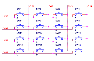 robust meteor
This for example? '
north stream
Yeah, that's the right idea.
narrow thorn
I am trying to play with a fastled sketch on the CPX.. the compile is failing with random() 'no matching function. though I have fastled.h and Adafruit_Playgroundexpress.h both included
#include <FastLED.h>
#include <Adafruit_CircuitPlayground.h>
wet crystal
@robust meteor https://www.youtube.com/watch?v=G14tREsVqz0

 robust meteor
Thanks for the video! though this doesn't fit my needs, as I need to recognize multiple presses at the same time
Keypad library can ^^
 bright depot
hello there! I have a project in mind. And its my 1st time working with Arduino. Anyone has some spare time to give me some tips and tricks. Or mistake i will propably do? I am not that expirienced....
wet crystal
If it doesn´t care you that im playing video games in the background
I think beginner to beginner expirence could be good
bright depot
@wet crystal sure 😄
 austere island
would anyone know how to read square payment app data from the Arduino
honest nimbus
.... what are you trying to do? Because I can't think of anything useful and non-nefarious.
north stream
Those things plug into an audio port, so I'm guessing they encode the data as audio tones, modem style? Sort of like the Project Mc2 Pixel Purse?
honest nimbus

Swipe swipe...data!
But like... Why credit card payment, OFF of a device that already has an internet connection and security certificate to handle payment data
 gleaming edge
does anyone know if there's a way to store data collected on an Arduino, without using an external shield/component?
if there is a way without using a shield / radio link
north stream
The Arduino has some onboard EEPROM storage you could use.
gleaming edge
Yeah just saw that.. it's 1 kb but probably good enough for my sampling rate
thanks!
wet crystal
Anyone can tell me about a chinese vendor which prints on plastic cards?
The vendor should be able to print security features as well
 pine bramble
i've got a project i'm working on with arduino and pi where i'd like to have a flask web server sending commands to the arduino via i2c. i have a basic example going where the pi can send commands by sending an integer to the adruino that the arduino then parses via switch case. i'm looking for some more resources on i2c as the ones i've read so far are either too basic in their examples or way too advanced
north stream
It sounds like you have I2C working, so I'm not sure what you're looking for here. I'm guessing some way to format the data so you can do more than send an integer?
pine bramble
that and the appropriate way to do this. right now it's one way master (pi) -> slave (arduino). the arduino also has physical controls for the outputs i'm trying to control via flask. so i would think having two way communinication to see the status of things would be needed. the main control is a momentary switch so i'm having trouble getting through how to deal with that via the flask
when reading i see a lot about bit registers and such and that is foreign to me
north stream
One possibility is to use Firmata, which lets you send and receive commands and data.
I've actually used Python to talk to an Arduino using Firmata. It's a little wonky to set up, but it works.
 proper pawn
hi : )
How do I blink the led Built into the Arduino board R3?
Just gotta check that my Uno works 😃
 stable forge
@proper pawn go to File->Examples->Basics->Blink, and compile and upload that.
proper pawn
yeh but that's requires a extra led
just need the to use the base leds already on the ardunio @stable forge
proper pawn
Oh but which is the builtin
referred too
Which "Example" teaches u about turning on/off the 5 volt output?
i googled it but I can't find much about it
stable forge
it's the one marked "L" on the board, near pin 13
https://learn.adafruit.com/ladyadas-learn-arduino-lesson-number-1/upload-your-first-sketch This is older and explicitly uses 13; the example code has since been generalized to use LED_BUILTIN, for boards where the builtin LED is not necessarily on 13.
This is an oldie but goodie video series: https://www.youtube.com/watch?v=fCxzA9_kg6s&list=PLA567CE235D39FA84

New Episodes each Monday! You can download the parts list and the code from this episode on my website: http://jeremyblum.com/2011/01/02/arduino-tutorial-ser...
proper pawn
Thanks @stable forge
 north kelp
What do you want to build, @pine bramble ?
pine bramble
Not sure honestly, trying to decide whether to get an arduino or a raspberry pi. I'm not good at programming yet and haven't worked with embedded stuff at at all. @north kelp
Was thinking maybe a trail camera (motion sensor activated camera), something to control sprinklers, things like that.