#help-with-arduino
1 messages · Page 24 of 1
 stable forge
 untold depot
stable forge
But there are no Serial reads in your program, so why would you expect it to acc...
untold depot
stable forge
But there are no Serial reads in your program, so why would you expect it to acc...
I mean text input from the board.
whatever Serial.println() is doing, it's not doing that anymore.
Here's the output from tio
[12:21:30.739] Connected
0```

And nothing else, even after waiting for over a minute.ok, "input" from the point of view of the host computer 🙂
and that is my test program, or just yours?
untold depot
stable forge
and that is my test program, or just yours?
yours
stable forge
untold depot
yours
testing some things... I am reproducing something similar
stable forge
untold depot
yours
This is being caused by the Arduino IDE itself. If you close the Arduino IDE, the board runs fine.
Why? is another question.
If the Serial Monitor is opened in Arduino IDE, it somehow grabs the serial connection from tio.
so it appears as if the board is going away. But with the blink program, it's still blinkin so I know it's still running. I see it printing numbers in the Arduino Serial Monitor.
void setup() {
  Serial.begin(115200);
  delay(2000);
  pinMode(LED_BUILTIN, OUTPUT);
}

int i = 0;
bool led = false;

void loop() {
  Serial.println(i);
  digitalWrite(LED_BUILTIN, led);
  delay(5000);
  led = !led;
  i++;
}
delay is 500 or 5000, doesn't matter, rather soon the Arduino Serial Monitor grabs the terminal. If I X it out it goes back to tio.
 untold depot
stable forge
delay is 500 or 5000, doesn't matter, rather soon the Arduino Serial Monitor gra...
untold depot
stable forge
delay is 500 or 5000, doesn't matter, rather soon the Arduino Serial Monitor gra...
I closed the IDE and I'm still having the issue in tio.
stable forge
make sure there isn't another window of the IDE open
I am seeing this in tio. The disconnect/reconnect is when I open/close the Serial Monitor:
[14:06:56.705] Disconnected
[14:07:12.722] Warning: Could not open tty device (No such file or directory)
[14:07:12.722] Waiting for tty device..
[14:07:30.741] Warning: Could not open tty device (No such file or directory)
[14:07:30.742] Waiting for tty device..
[14:07:36.748] Connected
0
12
[14:07:48.050] Disconnected
[14:07:52.056] Connected
3
4
[14:07:58.050] Disconnected
[14:08:08.061] Connected
7
[14:08:14.431] Disconnected
[14:08:15.432] Warning: Could not open tty device (No such file or directory)
[14:08:15.433] Waiting for tty device..
[14:10:04.548] Connected
22
23
i got suspicious because I tried the board on a Windows machine (not having sttarted Arduino IDE at all, just plugging it in), and it was fine.
untold depot
I even restarted to be sure nothing was running in the background, it's still occuring with tio. I also tried lowering the delay on the blink script and at 2100 this is the result
13:20:38.717 -> 4
13:20:40.809 -> 5
13:20:42.901 -> 6
13:20:45.028 -> 7
13:20:47.121 -> 8
13:20:49.216 -> 9
13:20:51.310 -> 10```

it made it to 10 but then stopped'yes, that's what I see when I have a delay of 500. It gets to about 10 before the Serial Monitor steals it back. But it is still blinking.
Maybe try rebooting the laptop, and then don't start up anything else except tio and see what happens. Maybe some other program is swiping /dev/ttyACM0
I also see odd things tlike the newlines get eaten before it goes away completely
and/or if you have another computer plug it in with a terminal program
untold depot
stable forge
Maybe try rebooting the laptop, and then don't start up anything else except `ti...
here's the output from tio after a reboot. After the output stopped for awhile I quit and relaunched tio and it started again for a bit, but then stopped.
[13:29:42.013] tio v2.5
[13:29:42.013] Press ctrl-t q to quit
[13:29:42.014] Warning: Could not open tty device (No such file or directory)
[13:29:42.014] Waiting for tty device..
[13:29:44.016] Connected
0
1

[13:30:19.267] Disconnected
arina@framework-i-sure-hope-it-does:~$ tio -b 9600 /dev/ttyACM0
[13:30:20.663] tio v2.5
[13:30:20.663] Press ctrl-t q to quit
[13:30:20.664] Connected
16
17
I already tried another linux laptop but I'll try my windows 10 desktop, see what happens
stable forge
untold depot
here's the output from tio after a reboot. After the output stopped for awhile I...
do you have modemmanager installed? Remove it if so: sudo apt purge modemmanager. It is fairly useless and can interfere with the serial port.
tio /dev/ttyACM0 is fine: you don't need to specify the baudrate
 tardy iron
oh! on most Unixes, if multiple processes have the same tty device open for reading, the kernel will round-robin read requests if there are multiple simultaneous ones. how many bytes each process receives could depend on how large a buffer each one passes to the read system call, up to some limit
stable forge
tardy iron
oh! on most Unixes, if multiple processes have the same tty device open for read...
I had no idea! I thought maybe it was exclusive access. But what else has it open?
untold depot
It worked find on the windows PC. I uninstalled modemmanager but it's still occurring.
stable forge
There is an Arduino Cloud thingamagig that I once installed and occasionally runs in the background.
You may need to reboot after the uninstall, if there is still a modemmanager process
tardy iron
stable forge
I had no idea! I thought maybe it was exclusive access. But what else has it ope...
it depends on whether the process specified exclusive access, and the exact semantics of that request on that OS. i don’t remember offhand whether Arduino IDE or tio try to request exclusive
stable forge
i don't remember encountering this issue with Serial Monitor before, but I have often found that it acts weirdly.
untold depot
stable forge
You may need to reboot after the uninstall, if there is still a modemmanager pro...
rebooted, same issue occurring
tardy iron
untold depot
It worked find on the windows PC. I uninstalled modemmanager but it's still occu...
since you’re on Linux, you might want to try lsof to look for what other processes have it open. sorry, i don’t have specific syntax offhand
stable forge
i was just going to say that.
$ lsof /dev/ttyACM0
COMMAND  PID    USER   FD   TYPE DEVICE SIZE/OFF NODE NAME
tio     6341 halbert    5uW  CHR  166,0      0t0 1816 /dev/ttyACM0
I just found the lsof thing on google too lmao, tio is the only program using ttyACM0
stable forge
maybe do sudo lsof /dev/ttyACM0 ; I was finding it was only listing my processes without sudo
e.g. lsof / vs sudo lsof /
untold depot
      Output information may be incomplete.
lsof: WARNING: can't stat() fuse.portal file system /run/user/1000/doc
      Output information may be incomplete.
COMMAND  PID  USER   FD   TYPE DEVICE SIZE/OFF NODE NAME
tio     5683 arina    5uW  CHR  166,0      0t0  754 /dev/ttyACM0
did you start arduino at all?
untold depot
stable forge
did you start arduino at all?
nope
stable forge
try plugging another board in first, to grab ACM0, and then plug the Pi Pico in, so it gets ACM1
are you using an external hub or anything unusual like that?
untold depot
no, but the Framework's USB-A ports are actually USB-C to USB-A converters in a slot
let me try a USB-C to USB-C cable
stable forge
i using a USB-C to -USB-A dongle, didn't make a difference
untold depot
tried both a C-C cable and plugging in another board, still having the issue.
I am monitoring ACM1
stable forge
what is the other linux laptop; is it running the same debian?
untold depot
I'm running Debian 12, the other laptop is running Debian 13
stable forge
if you have an RPi, you could try that. But it still doesn't narrow down what's unusual about your linux machines
untold depot
yeah lemme see if I can dig one up. I can also try my or my gf's home server (but they're also running Debian oops)
stable forge
untold depot
yeah lemme see if I can dig one up. I can also try my or my gf's home server (bu...
still, could be fine. I'm using ubuntu 24.04 so it should be about the same
and i don't see this
stable forge
untold depot
yeah lemme see if I can dig one up. I can also try my or my gf's home server (bu...
one more thing: do you have Cura installed (for a3d printer)? It tests all available serial ports to see if there's a 3d printer on the other end.
untold depot
no, but I do have PrusaSlicer.
stable forge
or Repetier
PrusaSlicer doesn't seem to be guilty of this: https://github.com/prusa3d/PrusaSlicer/issues/3676
untold depot
so I finally found my rpi 3 and tested tio on it and it works just fine. I have no idea what's going on.
stable forge
untold depot
so I finally found my rpi 3 and tested ``tio`` on it and it works just fine. I h...
I don't know what to say either. I think something is installed that is swiping the serial port. So maybe review dpkg --list, and maybe compare it with your gf's server, if that makes any sense.
 rain axle
I asked, and we'd entertain take a pull request / issue on that library.
 indigo socket
I'm looking to buy a ESP32 Dev board with integrated display. Any recommendations? something small like 1.9 inch
stable forge
indigo socket
I'm looking to buy a ESP32 Dev board with integrated display. Any recommendation...
These are 1.1" displays: https://www.adafruit.com/search?q=tft+feather
First three items here https://www.adafruit.com/search?q=tft+featherwing are displays that Feathers plug into conveniently. Matching Feathers: https://www.adafruit.com/search?q=esp32+feather
 slim tide
I assume it isn't possible, but just to check, would I be able to read inputs from a Bluetooth mouse if I don't have the dongle plugged into my microcontroller? I'm trying to use a Bluetooth mouse as a remote control and that's the major problem I'm facing
 vivid rock
indigo socket
I'm looking to buy a ESP32 Dev board with integrated display. Any recommendation...
vivid rock
indigo socket
I'm looking to buy a ESP32 Dev board with integrated display. Any recommendation...
I was happy using this one:
https://www.adafruit.com/product/5691
Like Missy Elliot, we like to "put our [Feather] down, flip it and reverse it" and that's exactly what we've done with this new development board. It's basically ...
stable forge
slim tide
I assume it isn't possible, but just to check, would I be able to read inputs fr...
If the microcontroller supports BLE, then you wouldn't need the dongle.
but the microcontroller software has to act as a BLE HID host for the mouse
slim tide
stable forge
If the microcontroller supports BLE, then you wouldn't need the dongle.
Excellent, thank you!
stable forge
this is not yet working in CircuitPython, for instance
slim tide
stable forge
but the microcontroller software has to act as a BLE HID host for the mouse
So would it just listen to whatever the mouse it saying or would it need to reply and confirm it exists?
slim tide
stable forge
this is not yet working in CircuitPython, for instance
I'm using the Arduino language
stable forge
the mouse would probably have to be paired with the microcontroller.
also note there may be BLE mice and Bluetooth classic mice. I don't remember which are more prevalent.
what microcontroller are you using?
slim tide
stable forge
what microcontroller are you using?
Whoops, meant to link the product page
I may just use a random controller I found lying around as that seems a bit easier to work with
slim tide
stable forge
a wired controller?
No
I'll check if it is
Says it's Bluetooth version: 2.1+EDR
stable forge
that sounds like classic Bluetooth
stable forge
slim tide
I'll give it a go. Thanks for the help!
it will not work with BLE libraries. ESP32 does support classic bluetooth, but I don't know anything about the libraries for classic bluetooth
slim tide
stable forge
it will not work with BLE libraries. ESP32 does support classic bluetooth, but I...
I've managed to discover the device I'm trying to connect to so I should be able to connect to it from here. Only problem is it isn't detecting channels, so I need to sort that out
slim tide
stable forge
it will not work with BLE libraries. ESP32 does support classic bluetooth, but I...
Sorry for the ping, it seems to be HID if you know anything about that
stable forge
slim tide
Sorry for the ping, it seems to be HID if you know anything about that
Classic Bluetooth uses "Profiles" for various HID devices, but I'm not familiar with the Arduino libraries for these.
To repeat, BLE (Bluetooth Low Energy) is not the same as classic Bluetooth. They have things in common but are not interoperable at all.
slim tide
stable forge
To repeat, BLE (Bluetooth Low Energy) is not the same as classic Bluetooth. They...
I know, I'm just kinda lost. I'll probably resort to controlling with my phone
stable forge
slim tide
I know, I'm just kinda lost. I'll probably resort to controlling with my phone
you might be interested in our Bluefruit Connect app: https://learn.adafruit.com/search?q=bluefruit%2520connect. But most projects we have use CircuitPython for the BLE side on the microcontroller. We don't have ESP32 BLE Arduino projects that I know of.
indigo socket
stable forge
These are 1.1" displays: <https://www.adafruit.com/search?q=tft+feather>
Thank you so much @stable forge I love Adafruit products and I just getting started with ESP32, so clear documentation is very important to me. I bought a generic one and my biggest problem is getting good documentation on it
indigo socket
looking for a good repository of sketches for ESP32-WROOM-32, any recommendations?
stable forge
indigo socket
looking for a good repository of sketches for ESP32-WROOM-32, any recommendation...
Select a board that uses that module in Arduino IDE, and then look in File->Examples, and find the "Examples for [that board], which will be just below the generic examples. The examples come from: https://github.com/espressif/arduino-esp32/tree/master/libraries. Each library has an examples directory. See https://docs.espressif.com/projects/arduino-esp32/en/latest/getting_started.html#examples, which also recommends https://techtutorialsx.com/category/esp32/
indigo socket
This is great information. Thanks!
 sand escarp
Hi! I have what I hope will be a quick question.
I have a QTPY SAMD21, a power BFF, and a I2C to 8 Channel Solenoid Driver.
Everything works when the QTPY is plugged into a computer and the Power BFF is plugged into a 12v adapter providing 2 amps.
It does NOT work when the QTPY is mated to the Power BFF.
Do I just need to get an adapter that provides more amperage? Would 4 amps be enough? Thank you in advance!

One additional note I forgot to add:
The QTPY powers on properly and sends serial data back to my computer. The green light on the solenoid driver board lights up as well. The solenoid however does not get energized.
stable forge
sand escarp
Hi! I have what I hope will be a quick question.
I have a QTPY SAMD21, a power...
does your sketch have a while (Serial) ... in it? That will wait forever if not connected to a computer.
sand escarp
stable forge
does your sketch have a `while (Serial) ...` in it? That will wait forever if no...
D'oh! Yep. That was exactly it. Thank you for your help!
untold depot
Hi, I'm trying to figure out how to setup this dac (https://learn.adafruit.com/adafruit-tlv320dac3100-i2s-dac) in arduino using the headphone port but all the arduino examples are for the speaker port. I know it's not as simple as just find/replace "speaker" with "headphone" because there's some functions that speaker mode uses but the headphone mode doesn't. Still in the "smashing example code together until it kinda works" phase of my arduino knowledge, would anyone be able to help me run the sine tone example in the headphone port?
stable forge
@mellow mural I would suggest putting a bunch of print statements in your program to log what is happening where, so you can narrow down which part of the program is failing.
then watch all that in the Serial Monitor
 mellow mural
stable forge
<@1436605955214278737> I would suggest putting a bunch of print statements in yo...
mellow mural
stable forge
<@1436605955214278737> I would suggest putting a bunch of print statements in yo...
Okk I'll try that right noww
stable forge
put print's before and after each significant thing (or in between, basically), so you can see if one particular line causes a hang or crash
The HC05 is an independent processor and is not necessarily going to disconnect when the Arduino program that is controlling it goes haywire.
 teal dagger
hi i am literally banging my head against the usb host functionality of the tinyusb stack, for the rp2350, my guess is that it still is buggy (philower builds) I tried the arduino usb host example and it works, when I now add hid code aka hid_mount undmount it is also called, but tuh_hid_report_received_cb is never called! The only reference I found to this issue is from 23 but no answer, does someone know?
i am calling tuh_hid_receive_report on mount
void tuh_hid_mount_cb(uint8_t dev_addr, uint8_t instance,
uint8_t const* desc_report, uint16_t desc_len) {
uint8_t proto = tuh_hid_interface_protocol(dev_addr, instance);
Serial1.printf("HID mount: addr=%u inst=%u proto=%u\r\n", dev_addr, instance, proto);
// Für Boot-Mouse/Keyboard auf Boot-Protokoll schalten (async)
if (proto == HID_ITF_PROTOCOL_MOUSE || proto == HID_ITF_PROTOCOL_KEYBOARD) {
tuh_hid_set_protocol(dev_addr, instance, HID_PROTOCOL_BOOT);
}
// vorsorglich ersten Report anfordern
tuh_hid_receive_report(dev_addr, instance);
}
thats the last point which is called, the received part later is not called anymore after that
maybe this is the culprit ? if (proto == HID_ITF_PROTOCOL_MOUSE || proto == HID_ITF_PROTOCOL_KEYBOARD) {
tuh_hid_set_protocol(dev_addr, instance, HID_PROTOCOL_BOOT);
}
could be
stable forge
teal dagger
hi i am literally banging my head against the usb host functionality of the tiny...
I don't know the answer but we use the TinyUSB host impl in CircuitPython so you could at the implementation there.
mellow mural
stable forge
The HC05 is an independent processor and is not necessarily going to disconnect ...
Yeah so I did something
And it kinda works
But there's still one problem
When I give it a few commands one after another
It stops working
It does continue to recieve the Commands coz the RX light lights up whenever I type the command from my Bluetooth terminal
But it does not make the motor rotates accordingly
I can show the code if you want?
stable forge
you can upload the code with the + button to the left
 teal dagger
stable forge
I don't know the answer but we use the TinyUSB host impl in CircuitPython so you...
teal dagger
stable forge
I don't know the answer but we use the TinyUSB host impl in CircuitPython so you...
unfortunately I cannot use circuitpython for my case. This looks like a more stripped down example: https://git.fh-aachen.de/gk6394s/tinyusb/-/blob/master/examples/host/cdc_msc_hid/src/hid_app.c but if that does not work out as well then my guess is that the rp2350 drivers are borked in this area and I have to move to another harware. Circuitpython does not do it for my case unfortunately due to latency issues it introduces, been there done that. The issues were the reason why I ported my code to C to begin with. That fixed my issues and up until I hit the USB part things were running smoothly!

GitLab
tinyusb fork with minimal modifications
teal dagger
my personal guess is this stuff simply does not work, the examples themselves do not test for signals received and those are the base for the tests, I guess and usb hosting is a corner case literally no one touches on that board
stable forge
teal dagger
unfortunately I cannot use circuitpython for my case. This looks like a more str...
I was suggesting looking at the CircuitPython source code for how it does USB host, even if you can't do it directly. There is basic support in https://github.com/adafruit/circuitpython/tree/main/shared-module/usb/core. However, a lot of the specific device support is written in Python.
But I am not sure RP2350 has native USB host support yet: https://github.com/hathach/tinyusb/discussions/3329
There is PIO USB host support which was done for RP2040, and there is also MAX3421E support.
Have you looked at https://github.com/raspberrypi/pico-examples/tree/master/usb/host/host_cdc_msc_hid
teal dagger
rp2350 has native usb host support, pio usb, never could get it properly to run 🙁 thanks for the info. It was an initial joy when i finally got a usb plug detection and wham just to hit the next problem 😄. Frickking annoying because i am soo close to what I want to achieve just to hit a final roadblock! Could be I assume that the host support is not fully finished yet driverwise in tinyusb for this chipset, probably shelling out the few bucks for another microcontroller might be wiser than sinking more time into that one. Question is which chipset works really well for usb host mode! Mhh the examples have a full stack sitting on top, thanks for the link I will look into them!
ok i had a look at the example, it really implements a full host, and is adding the proper configs and hooks for the rp2350 as it seems, I will give this one a shot, it seems easy enough to be integrated as starting point, not having to go into the usb details
thanks for the link, really helpful
i really love the rp2350 btw.... definitely a very good package in what it can do
... that is theoretically
i guess you can make a career by simply programming a full usb stack.. bluetooth is even worse
sand escarp
https://learn.adafruit.com/adafruit-audio-bff/arduino
I'm trying to use the example here with a RP2040 as demonstrated but can't get the code to compile. I always get this error:
/Users/john/Library/Mobile Documents/com~apple~CloudDocs/Arduino/qtpy_audio_bff_example_2/qtpy_audio_bff_example_2.ino: In function 'void setup()':
/Users/john/Library/Mobile Documents/com~apple~CloudDocs/Arduino/qtpy_audio_bff_example_2/qtpy_audio_bff_example_2.ino:46:30: error: 'FIFO_SDIO' was not declared in this scope
46 | #define SD_CONFIG SdioConfig(FIFO_SDIO)
|
/Users/john/Library/Mobile Documents/com~apple~CloudDocs/Arduino/qtpy_audio_bff_example_2/qtpy_audio_bff_example_2.ino:60:17: note: in expansion of macro 'SD_CONFIG'
60 | if (!sd.begin(SD_CONFIG)) {
|
Multiple libraries were found for "SdFat.h"
Used: /Users/john/Library/Arduino15/packages/rp2040/hardware/rp2040/5.4.2/libraries/SdFat
Not used: /Users/john/Library/Mobile Documents/com~apple~CloudDocs/Arduino/libraries/SdFat_-_Adafruit_Fork
exit status 1
Compilation error: 'FIFO_SDIO' was not declared in this scope
Removing the SdFat folder from the RP2040 so it defaults to the Adafruit fork doesn't seem to solve it. Any suggestions?
 inland gorge
sand escarp
https://learn.adafruit.com/adafruit-audio-bff/arduino
I'm trying to use the exa...
inland gorge
sand escarp
https://learn.adafruit.com/adafruit-audio-bff/arduino
I'm trying to use the exa...
It looks like the SdFat library in the "arduino-pico" Arduino core has been updated and that FIFO_SDIO has been scoped to just for Teensy boards. So, I think what one does now is instead of this block:
#if HAS_SDIO_CLASS
#define SD_CONFIG SdioConfig(FIFO_SDIO)
#elif  ENABLE_DEDICATED_SPI
#define SD_CONFIG SdSpiConfig(SD_CS_PIN, DEDICATED_SPI, SPI_CLOCK)
#else  // HAS_SDIO_CLASS
#define SD_CONFIG SdSpiConfig(SD_CS_PIN, SHARED_SPI, SPI_CLOCK)
#endif  // HAS_SDIO_CLASS
have this block instead:
// Try to select the best SD card configuration.
#if defined(HAS_TEENSY_SDIO)
#define SD_CONFIG SdioConfig(FIFO_SDIO)
#elif defined(HAS_BUILTIN_PIO_SDIO)
// See the Rp2040SdioSetup example for boards without a builtin SDIO socket.
#define SD_CONFIG SdioConfig(PIN_SD_CLK, PIN_SD_CMD_MOSI, PIN_SD_DAT0_MISO)
#elif ENABLE_DEDICATED_SPI
#define SD_CONFIG SdSpiConfig(SD_CS_PIN, DEDICATED_SPI, SD_SCK_MHZ(16))
#else  // HAS_TEENSY_SDIO
#define SD_CONFIG SdSpiConfig(SD_CS_PIN, SHARED_SPI, SD_SCK_MHZ(16))
#endif  // HAS_TEENSY_SDIO
I've not found a good description of this change. I'm going purely on the example here: https://github.com/greiman/SdFat/blob/master/examples/SdInfo/SdInfo.ino
sand escarp
inland gorge
It looks like the `SdFat` library in the "arduino-pico" Arduino core has been up...
Wow thank you so much! That totally did the trick!!
I really appreciate it
 spiral granite
Guys i need help
Trying to make a simpel temparature messure
I bought an NTC Sensor
Using an ESP32S3 Dev
Sensor has around 10k ohm at 24 degree
REF R is also a 10k
3.3v goes to REF R in
REF R out goes to PIN 35 and NTC front
NTC back goes to gnd
Code is this:
// Define constants
const int thermistorPin = 35; // Pin connected to the thermistor
const float referenceVoltage = 3.3;
const float referenceResistor = 10000; // the 'other' resistor
const float beta = 3950; // Beta value (Typical Value)
const float nominalTemperature = 25; // Nominal temperature for calculating the temperature coefficient
const float nominalResistance = 10000; // Resistance value at nominal temperature
void setup() {
Serial.begin(115200); // Initialize serial communication
pinMode(thermistorPin, INPUT); // Set pin as input
}
void loop() {
int adcValue = analogRead(thermistorPin); // Read ADC value
float voltage = (adcValue * referenceVoltage) / 4095.0; // Calculate voltage
float resistance = (voltage * referenceResistor) / (referenceVoltage - voltage); // Calculate thermistor resistance with updated configuration
// Calculate temperature using the Beta parameter equation
float tempK = 1 / (((log(resistance / nominalResistance)) / beta) + (1 / (nominalTemperature + 273.15)));
float tempC = tempK - 273.15; // Get temperature in Celsius
float tempF = 1.8 * tempC + 32.0; // Get temperature in Fahrenheit
//Print temperature
printf("TempC: %.2f C\n", tempC);
printf("TempF: %.2f F\n", tempF);
delay(300); // Wait 1 second
}
I see the temp in the serial monitor but its constantly -273.15 ?
Why what is wrong
I checked and replaced all the wires, even replaced the sensor and resistor
Its not working
 sharp turret
spiral granite
Guys i need help
Trying to make a simpel temparature messure
I bought an NTC Se...
sharp turret
spiral granite
Guys i need help
Trying to make a simpel temparature messure
I bought an NTC Se...
is Pin 35 of that board analog capable?
spiral granite
Nope found that out now
Changed to 17 its working now
The only thing wrong now is the temparature
It says 64 degrees but its around 23 in my room hahaha
But it increases when i touch the NTC
 leaden walrus
float voltage = (adcValue * referenceVoltage) / 4095.0; // Calculate voltage
the 4095 here would be for a 12bit return from analogRead()
arduino default is 10 bit
try changing 4095 to 1023
or add a call to analogReadResolution() in setup() and set it to 12:
analogReadResolution(12);
 river bloom
Hi friends. I was wondering if you g if anyone knew the Pinot for the adafruit 2.7” eink display with 5 buttons. I want to wire it to an ESP32.

 leaden walrus
river bloom
Hi friends. I was wondering if you g if anyone knew the Pinot for the adafruit 2...
teal dagger
stable forge
I don't know the answer but we use the TinyUSB host impl in CircuitPython so you...
leaden walrus
river bloom
Hi friends. I was wondering if you g if anyone knew the Pinot for the adafruit 2...
teal dagger
stable forge
I don't know the answer but we use the TinyUSB host impl in CircuitPython so you...
Just to answer... the problem simply was the Arduino stack, it turned out that the Philower stack is buggy in this area, I now have moved away from platform.io (no direct Pico SDK support, and philower code is not working in the usb host area properly) to raw Pico SDK and cmake, and things work now as expected. I was able to modify the example to get the data via host mode from an attached mouse and now see the x and y input diffs! Thanks everybody for the help! Good thing is, it is not tinyusb, I still use it, but on lower level, with the Arduino SDK part out of the mix and a raw sdk build instead of an adapted one!
not sure why the philower stack does not work, I guess the sdk integrated might be buggy
stable forge
teal dagger
Just to answer... the problem simply was the Arduino stack, it turned out that t...
Is there an open issue on the philhower core? If not, I’m sure they would appreciate one.
teal dagger
Yes I have been thinking about sending an issue in, but I am not sure whether the problem is in my platform Io setup or the philower code, I have to isolate the issue to a swallowable chunk
 lilac shard
how do i configure my esp 8266 with dashboard toggle buttons?
 rapid kraken
If I want to use a XIAO RP2040 board as an I2C peripheral, I need to set pull-up resistors for SDA and SCL, right? Can I do that via code or do I need to solder resistors onto it? Same for if I use it as the master?
rapid kraken
Hm. I can add ditigalWrite(SDA, HIGH); and same for SCL but still get an error on the master side about needing pull-ups.
Actually, I get an ETIMEDOUT first and then the error, so that might be a different issue.
stable forge
rapid kraken
If I want to use a XIAO RP2040 board as an I2C peripheral, I need to set pull-up...
The internal pull-up resistors on GPIO pins are quite weak: 60-85k. 10k is a better value for I2C pullups, so better to use external resistors.
You would use pinMode(pin, INPUT_PULLUP); to use the internal pullups.
rapid kraken
I think they're enough by default, actually - I can get the message on the peripheral and process it, but it's failing after I receive the command
So not sure what the issue is yet, but I don't think it's the resistors
stable forge
rapid kraken
I think they're enough by default, actually - I can get the message on the perip...
they are marginal, and might sort of work. You might try just adding them temporarily to see if it makes a difference. Many off-board I2C devices specify at least 10k or even 4.7k
rapid kraken
okay, let me try that
 proper heart
rain axle
I asked, and we'd entertain take a pull request / issue on that library.
proper heart
rain axle
I asked, and we'd entertain take a pull request / issue on that library.
Sorry for the late reply. The state my fork is in right now works, but not every functionality of the chip is implemented yet. In the planning for my project I will continue software development at the end of January, I'll have time to properly test everything. I'll reach out when it is finished in februari through a PR or issue
 solid sail
Hey! I’m working on a small project where an ultrasonic distance sensor sends an IR signal, and another Arduino receives it and turns on an LED. Everything basically works, but I have one annoying issue: ⚠️ The LED keeps pulsing or flickering instead of staying on. It looks like the IR signal is being sent repeatedly, which makes the receiver constantly re-trigger the LED. I want the LED to stay on smoothly without pulsing but still keep all the features (distance detection, IR sending, IR receiving). Does anyone know how I can make the LED stay solid without losing the IR functionality? Thanks in advance! 🙏The code is right below
stable forge
solid sail
Hey! I’m working on a small project where an ultrasonic distance sensor sends an...
I'm not sure what you mean. Do you mean that despite the digitalWrite(LED, HIGH);, when loop() is running, the LED goes off?
inside the loop, once there's reception, it should just stay on, as I think you're assuming.
I wonder if your program is restarting over and over for some reason. You could put a Serial.println("Entering loop") at the top of loop() and see whether it prints multiple times.
solid sail
stable forge
I wonder if your program is restarting over and over for some reason. You could ...
I'll try. Thank you for the reply.
 haughty plover
so i got an Arduino Plug and Make Kit: Game Controller, and i got the modulino buttons and the modulino movements connected toghether, i setted the modulino A button to S key of my keyboard (reverse), a button to s key of my keyboard (reverse), B button to spacebar key of my keyboard (handbrake), C button to W key of my keyboard (foward), i want to use the buttons as an controllers to use to drive an car in BeamNG.drive, the issue is that when i press the C button it doenst go fowards it just barely revs the engine, the same whit the A button. im using an arduino uno r4 wifi.
here is the code
Does anyone know how to do it? I wanted to use the modulino button to drive the car and use the movement modulino to steer the car.
 thin latch
HEy people. im in a project trying to make a car with a esp32 and the controls ae a wifi connevtion via ip adress. i keep getting This site can’t be reached or Eek! Connection Failed! Check Wi-Fi password or Static IP conflict!. Can someone go through my code? Thanks
 quasi siren
Hi there!
Trinket M0 via Arduino IDE
I'm looking to set up a simple USB "Joystick" or "Gamepad" that utilizes two digital pins for button presses. Hoping someone can help me out!
 supple egret
a carry over from the help-with-CircuitPython channel
Well @stable forge, I have a PICO acting like a network device over USB and implementing a telnet-to-serial bridge at multiple baud rates. 👍🏼
I am cleaning up the code, 3D printing a case (to make it beautiful), and will post it to show-and-tell.
I will likely also order the Seeed XIAO 2040 to make an ultra-tiny version.
stable forge
supple egret
_a carry over from the help-with-CircuitPython channel_
Well <@3297662240932495...
fantastic!
 shut oyster


I moved my sensor to a proto-board for my raspberry pi and it's not detecting the i2c
I did a bunch of continuity tests and it's all kinda pointing to the sensor being dead but I just want some confirmation before I order a new one
I soldered and desoldered the hll out of the sensor so it took a bunch of heat damage
sharp turret
shut oyster
That joint is a recipe for disaster. You should have cut those wires off (or cleanly soldered them.)
Very likely causing a short.
 shut oyster
sharp turret
That joint is a recipe for disaster. You should have cut those wires off (or cle...
shut oyster
sharp turret
That joint is a recipe for disaster. You should have cut those wires off (or cle...
How though
I wasn't using those anymore
They were the old joints
sharp turret
There are traces in the PCB that connect the pins together.
rapid kraken
Is there a way to list all defined constants? I'm trying to make something like if defined(ESP8266) but for the boards I'm using (QT Py RP2040 and XIAO RP2040)
stable forge
rapid kraken
Is there a way to list all defined constants? I'm trying to make something like...
there's a huge list. If you do a build with V=commands, you'll see the command lines with all the -D... options.
if you want to see the value of a particular Makefile constant (NOT .h c preprocessor constant), you can do make BOARD=whatever print-CIRCUITPY_WHATEVER and the Makefile variable value will be printed (and nothing will be built)
rapid kraken
stable forge
there's a huge list. If you do a build with `V=commands`, you'll see the command...
Where does the V=commands go?
stable forge
I"m sorry, I thought you were talkign about CircuitPython. What is said is irrelevant for Arduino.
rapid kraken
oh okay, thanks
stable forge
you can look in the board support packages for the constants. I'll find some examples
stable forge
rapid kraken
Where does the `V=commands` go?
in the boards.txt file in a particular board support package, the board name constant is listed like this:
adafruit_qtpy.build.board=ADAFRUIT_QTPY_RP2040
Hm. Where do I find the board support packages?
stable forge
on Linux, in ~/.arduino15/packages. Similar locations on other OS's. The originals are in various GitHub repos.
~/.arduino15/packages/rp2040/hardware/rp2040/5.4.1/boards.txt for example
rapid kraken
thank you!
Hm. I feel like this should be right, but I'm getting errors about the constants not being defined.
#if defined(ADAFRUIT_QTPY_RP2040)
  #define PIN_DATA  28
  #define PIN_WS    27
  #define PIN_BCK   26
  #define PIN_SD_CS 29
#elif defined(SEEED_XIAO_RP2040)
  #define PIN_DATA  27
  #define PIN_WS    28
  #define PIN_BCK   29
  #define PIN_SD_CS 26
#endif
The ones I'm making
/home/kevin/Arduino/I2C_MP3_Module/setup.ino:3:21: error: 'PIN_DATA' was not declared in this scope
    3 |   config.pin_data = PIN_DATA;

ADAFRUIT_QTPY_RP2040 is in orange, which I assume means it's defined.
Does it need to be in the main file? where i'm using them?
nope, that's not it
hm, so it's not finding the ADAFRUIT_QTPY_RP2040 - because I can put it into an #else and it works
also not finding SEEED_XIAO_RP2040 if I plug one in
so those board values are either not right or not being set
manual (have to uncomment and comment), but at least it compiles
int pin_data = 28, pin_ws = 27, pin_bck = 26, pin_sd_cs = 29; // Adafruit QT Py RP2040
//int pin_data = 27, pin_ws = 28, pin_bck = 29, pin_sd_cs = 26; // SEEED XIAO RP2040
 dusk orchid
rapid kraken
dusk orchid
rapid kraken
try checking for ARDUINO_{boardDefineName} which seems to be how the board variants get defined in esp32 + RPi Pico land, so ARDUINO_ADAFRUIT_QTPY_RP2040
We have a few examples of defines we switch on here (picos near the end): https://github.com/adafruit/Adafruit_Wippersnapper_Arduino/blob/main/src/Wippersnapper_Boards.h
See platform.txt for the exact bit, but the esp32 one looks like this: -DARDUINO_{build.board}
https://github.com/espressif/arduino-esp32/blob/master/platform.txt#L151
stable forge
@dusk orchid is exactly right.
rapid kraken
dusk orchid
try checking for ARDUINO_{boardDefineName} which seems to be how the board varia...
Thank you!! Looks like that worked
 terse smelt
I'm trying to port this library for use on my UM PROS3 with Arduino and PlatformIO: https://github.com/jtothebell/z8lua/tree/42d7801d36b427fcb2541e4ebcfc64a70d11579e
for some reason I get this error on everything that mentions any standard C++ library, even after renaming all C files to have C++ extensions:
In file included from lib/z8lua/lua.h:16,
                 from lib/z8lua/eris.c:43:
lib/z8lua/luaconf.h:549:10: fatal error: cstdint: No such file or directory
 #include <cstdint> // for int16_t
          ^~~~~~~~~
compilation terminated.
I've been stuck on this for days, any ideas?
GitHub
🧩 A Lua fork that supports PICO-8 syntax extensions and zero-based tables, part of ZEPTO-8 - GitHub - jtothebell/z8lua at 42d7801d36b427fcb2541e4ebcfc64a70d11579e
Ok it seems I managed to fix it, but now I've come across another issue:
In file included from src/source/cart.cpp:21:
src/source/emojiconversion.h:11:17: error: 'u32string_view' in namespace 'std' does not name a type
     static std::u32string_view to_utf32[256];
string_view doesn't seem to exist, and same with u32string_view. This happens even after including <string_view> as well.
 oblique nova
is that a C++ version thing? are you able to force your build to use c++17 or higher?
terse smelt
oblique nova
is that a C++ version thing? are you able to force your build to use c++17 or hi...
I tried that and it didn't make a difference
 misty fable
Hey guys, does adafruit make a breakout board for those 5pin 0.5mm ZIF connectors? I have a mini thumbstick that I wanted to use on my Arduino project
 sharp turret
misty fable
Hey guys, does adafruit make a breakout board for those 5pin 0.5mm ZIF connector...
sharp turret
misty fable
Hey guys, does adafruit make a breakout board for those 5pin 0.5mm ZIF connector...
They sell these breakouts: https://www.adafruit.com/product/334 which work with these thumbsticks: https://www.adafruit.com/product/3103.
So you might look at that one to see if it'll work for you. (You'd just ignore the silkscreens)
(I can confirm the breakout works with the PSP thumbstick they sell.)
misty fable
sharp turret
They sell these breakouts: <https://www.adafruit.com/product/334> which work wit...
Yea, I saw that one but I need a 5pin, so this one wouldn't work unfortunately
sharp turret
Boo
inland gorge
misty fable
Yea, I saw that one but I need a 5pin, so this one wouldn't work unfortunately
How about these https://amzn.to/4oCDxaI

FFC/FPC Connectors are used to connect flexible cables or flexible printed circuit boards in electronic equipment, to provide reliable electrical connection and mechanical fixation, and are suitable for applications requiring high flexibility and compact design. Mainly used in various digital c...
misty fable
inland gorge
How about these https://amzn.to/4oCDxaI
Bought them yesterday, they'll arrive on Sunday, they just looked like a 6pin on the picture
inland gorge
misty fable
Bought them yesterday, they'll arrive on Sunday, they just looked like a 6pin on...
Perhaps because they have many different sizes? I think it was these I got a different-sized one for
misty fable
inland gorge
Perhaps because they have many different sizes? I think it was these I got a dif...
There were many options and I chose 5 pins but it was the only option where the picture didn't change, so hopefully they will send the correct one
 cyan raptor
So I picked up these boards and I'm trying to flash them and all 3 say error wrong boot mode. Anyone know what I'm doing wrong?


Nevermind guess I just wasn't holding the boot pin hard enough worked that time
 sharp schooner
cyan raptor
Nevermind guess I just wasn't holding the boot pin hard enough worked that time
sharp schooner
cyan raptor
Nevermind guess I just wasn't holding the boot pin hard enough worked that time
long press boot and release it will go to boot mode
misty fable
hey guys, what is the proper size screws for those TT Motors?
stable forge
misty fable
hey guys, what is the proper size screws for those TT Motors?
for the threaded shaft? It can be 2.5mm or 3mm
misty fable
What length tho?
stable forge
hold on ...
misty fable
I'm at Walmart looking for M3 30mm which is what Google told me but I can't find it so if you know an alternative please let me know
stable forge
misty fable
I'm at Walmart looking for M3 30mm which is what Google told me but I can't find...
short answer is that our older stock was M3 and our newer stock is M2.5
does Walmart have M2.5?
@misty fable ^^
stable forge
misty fable
I'm at Walmart looking for M3 30mm which is what Google told me but I can't find...
aare these the plastic shaft or metal shaft?
i have motors in front of me
misty fable
stable forge
does Walmart have M2.5?
They do not 😢
stable forge
misty fable
They do not 😢
the plastic shaft are even skinnier than M2.5 - M 2.5 doesn't fit. These are the yellow-body ones. The blue ones are metal shaft (or at least that's what I ahve)
stable forge
misty fable
They do not 😢
with no wheel on the shaft my 10mm screws only go in 8-9mm, so 30mm is may be long, but it depends on the length of the wheel axle hole.
Home Depot stocks very little in the store. a few M3, nothing smaller
the plastic shaft motors I think use a self-tapping screw
stable forge
I empathize with you standing in Walmart 🙂
misty fable
Yea, the wheels arrived late in the day today and the screws I have were not long enough
stable forge
hobby shops with RC cars sometimes have hw like this, or maybe Grainger
misty fable
I have a home Depot right next to my house but they were closed, I'll check them tomorrow
rapid kraken
I have a music player that receives communications in I2C. Whenever a message comes in, I get static or stuttering on the music being played. I'm guessing that that means that it's using the same thread and the processing needs to happen faster / on another thread?
I'm using Wire.onReceive(processI2C); to set up the processing.
Wire.onReceive is just an alert, right? Maybe I shouldn't be processing in there, just kick off processing elsewhere.
By adding a setup1() and loop1() function to your sketch you can make use of the second core. Anything called from within the setup1() or loop1() routines will execute on the second core.
I think this is what I need
Will test and report back
That's not the issue
Any idea why I might get static when I2C commands come in? If it's not the processing, that seems weird. I don't imagine it'd be any sort of electrical interference.
rapid kraken
Okay, nothing to do with the I2C commands -- because I can use a simpler MP3 and it does none of the static. So that (I think) narrows it down to the MP3 decoding. So nevermind on the above - I will go back to talking to the decoder library guy.
misty fable
inland gorge
How about these https://amzn.to/4oCDxaI
EUREKA!
These worked
rapid kraken
rapid kraken
Okay, nothing to do with the I2C commands -- because I can use a simpler MP3 and...
Actually - it does this when the controller board connects as well, regardless of what's playing.
So that's (a separate but related?) issue
I almost wonder if I shouldn't try something other than I2C (UART?) to see how it behaves
rapid kraken
Well, switching to UART gets rid of the horrible sound on connect -- so that's a step in the right direction
I2C feels more flexible but honestly I'm fine using UART
 gilded heron
I have an ESPRESSIF ESP32-C6-DevKitC-1 and Arduino IDE 2.3.6. When I connect on COM 6 (via USB) and select ESP32 DEV MODULE port 6 I get an error saying "not connected select proper board and port to connect automatically". I just can't seem to get my Arduino IDE to talk to my board. Any help would be greatly appreciated.
 thick stag
@gilded heron What do you have selected under Tools -> Board?
You'll need to make sure the type of board you're using is selected.
https://docs.espressif.com/projects/arduino-esp32/en/latest/installing.html
gilded heron
ESP32C6 DEV MODULE. Thanks.
shut oyster
How often do you guys get faulty sensors / boards ?
thick stag
gilded heron
ESP32C6 DEV MODULE. Thanks.
Sorry, can't tell if you figured it out or are still stuck. Any luck with the link?
thick stag
shut oyster
How often do you guys get faulty sensors / boards ?
Almost never.
How often do I accidentally short something? Often.
How often has something been wired incorrectly? Also quite often.
Could be a good time to get out a multimeter and learn how to check if things are as expected. If not, you can try and solder to fix it.
shut oyster
thick stag
Almost never.
How often do I accidentally short something? Often.
How often has...
I used a mutimetee and tested basically every avenue
Literally all the signs were correct
So that’s why i was so dumbfounded when literally nothing worked especially k owing i wired it correctly with a previous sensor of the same type, wiring, same microcontroller
thick stag
It definitely does happen. Kind of like the opposite of winning the lotto 🙃
Definitely more likely to happen with cheaper components that probably were not QA'd as thoroughly
rapid kraken
shut oyster
How often do you guys get faulty sensors / boards ?
So far, once ever, so <1%.
shut oyster
thick stag
Definitely more likely to happen with cheaper components that probably were not ...
Ugh I got one adafruit sensor, and then when i tried desoldering i messed it up and fried it
then i ordered a cheap alibaba $1 clone and that one did absolutely nothing
So i threrw away both
 sand sail
hi, can someone please help me my arduino r4 wifi is not detected in the ide
i think it's a problem with my driver


 rose moss

I accidentally plugged the lipo incorrcetly on my feather M0 express and need to determine which component is the charging chip
I dont know if its the top right one or the one near the bottom left


 tawdry shuttle
Does anybody have experience with the Metro ESP32 S3 and deep sleep mode? The Adafruit docs say a 150 micro amp draw is doable in deep sleep mode, but I am doing everything they show on that page and still seeing 2mA with the Neopixel cut and even the power LED desoldered.
stable forge
tawdry shuttle
Does anybody have experience with the Metro ESP32 S3 and deep sleep mode? The Ad...
See https://learn.adafruit.com/deep-sleep-with-circuitpython/power-consumption and other parts of that guide, including the examples.
Try a 9.x version of CircuitPython and see if it makes a difference. If so, there's a regression.
 dry needle
My ESP32-S3 Reverse TFT Feather from DigiKey just arrived, but im having trouble flashing it. I'd like to use c++, not circuitpython.
The default automatic flashing in both arduino and platformio is not working. After the flasher issues the reset command to begin flashing the board, the screen of the ESP freezes but flashing fails to find the device on the com port, erroring with
COM6 failed to connect: Cannot configure port, something went wrong. Original message: PermissionError(13, 'A device attached to the system is not functioning.', None, 31)
I've tried entering the TinyUF2 bootloader and the ESP-Builtin bootloader, they both work fine. I've updated the TinyUF2 bootloader to 0.35 (from 0.12.3 which is preinstalled), but the problem persists.
Monitoring the Serial output of the preinstalled program on COM6 works fine. Its the right COM port.
Flashing the ESP by manually putting it into TinyUF2 bootloader mode, building a .uf2 file from my compiled .bin and then copying it to the TinyUF2 USB storage device works to update the program on the ESP, but it is very cumbersome and requires manually pushing buttons on the ESP. Surely this can't be the only way.
Is this behavior normal for the device I have or is this unexpected/a defect? I've used platformIO successfully before with various ESP32 and ESP8266 devices and never had such issues.
tawdry shuttle
stable forge
Try a 9.x version of CircuitPython and see if it makes a difference. If so, ther...
I am running C++ in Arduino
leaden walrus
@dry needle what happens if you try uploading the arduino blink example but first put the board in ROM bootloader mode?
dry needle
leaden walrus
<@214501981648060416> what happens if you try uploading the arduino blink exampl...
Ok resolved now.
Had to use Zadig to assign the right drivers for the ESP HW bootloader interfaces, then add -D ARDUINO_USB_MODE=1 to my PlatformIO build args. Then, I had to enter ESP HW bootloader mode manually once (D0+Reset) and upload. From then on, the automatic upload+reset works without entering HW bootloader manually.
 wet tiger
I think in Arduino uno we can write only c or c++ right! But we can't write python?
inland gorge
wet tiger
I think in Arduino uno we can write only c or c++ right! But we can't write pyt...
Correct. The normal Arduino Uno has an 8-bit ATmega328 processor with only 2kB of RAM. This limits you to the C/C++ of the Arduino language. There are other compiled languages that can also work, like Rust
tardy iron
if you want something interactive on Arduino Uno, you could use Forth. but that’s a bit of a niche language these days
stable forge
wet tiger
I think in Arduino uno we can write only c or c++ right! But we can't write pyt...
https://sneklang.org/ is a minimal Python-like language that can run on Arduino Uno's.
Arduino Uno is an old weak choice now, with limited RAM and flash. There are many more modern choices with much more capability. There is Arduino support for many, many boards and chips.
oblique nova
tawdry shuttle
I am running C++ in Arduino
(I don't have this board, so just curious) how is the board powered, and how is the power measured? (I could be wrong, but the code seemed to be switching at 1 second intervals between sleep modes; so was wondering if you also spotted any differences between the sleep modes.)
tawdry shuttle
oblique nova
(I don't have this board, so just curious) how is the board powered, and how is...
I am using a Nordik PPK2 to measure power. So I can see on a graph the power draw at the various states
oblique nova
tawdry shuttle
I am using a Nordik PPK2 to measure power. So I can see on a graph the power dra...
Nice. Just curious - what are you seeing for the power consumptions for the 3 states the code is cycling through? (I.e., active with led, light sleep and deep sleep)
wet tiger
guys i going to prepare a document on cigare and alcho sensor .but i don't the process of praparing document and code writting can anyone help me
 snow path
Meow, im trying to make a coil winder with the ability to count the turns, but im getting unpredictable behavior from it, im sure my code sucks, i suck at programming and i try my best to avoid it
 snow path
Meow, im trying to make a coil winder with the ability to count the turns, but i...
snow path
snow path
Meow, im trying to make a coil winder with the ability to count the turns, but i...
(With variable speed)
 heavy hedge
My Arduino R4 Wi-Fi is repeatedly power cycling when I use a 9V battery (barrel jack). I tested the battery and it is good. It also intermittently works. Can anyone help me with this?
stable forge
heavy hedge
My Arduino R4 Wi-Fi is repeatedly power cycling when I use a 9V battery (barrel ...
What kind of 9V battery is it? Alkaline? Someone testing the R4 found it could draw 175 mA when wifi is in use. You may be seeing voltage sag. Put a voltmeter on the battery and see what the voltage looks like.
heavy hedge
stable forge
What kind of 9V battery is it? Alkaline? Someone testing the R4 found it could d...
The battery is Alkaline. It is a Rayovac brand battery
stable forge
measure the battery voltage when it's connected, and also measure the 5V pin on the board to see if it sags below that
heavy hedge
stable forge
measure the battery voltage when it's connected, and also measure the 5V pin on ...
What do I measure it with?
stable forge
do you have a multimeter?
heavy hedge
stable forge
do you have a multimeter?
Yes. The issue might be due to the ESP32-S3-MINI onboard the Arduino R4 Wi-Fi pulling to much power from the battery
stable forge
The mAh rating of such a battery is only about 550 mAh, so it might only last a few hours, and may not be able to supply sufficient current when wifi is in use
or if you are driving other things (like motors, ec.)
heavy hedge
stable forge
The mAh rating of such a battery is only about 550 mAh, so it might only last a ...
That makes sense. When I used it on USB, there was no power cycling
stable forge
if it works fine with a 9V wall wart or similar, then choose a stronger battery. 9V batteries are pretty wimpy
heavy hedge
stable forge
if it works fine with a 9V wall wart or similar, then choose a stronger battery....
Would this work?
 stable forge
yes, but a 5v adapter would also work, connected to the USB jack
6v-24v on the barrel jack. It uses a buck converter, which is good -- more efficient than a linear regulator, which wil just waste higher voltage as heat.
heavy hedge
stable forge
yes, but a 5v adapter would also work, connected to the USB jack
It works!
stable forge
if you have that adapter in hand, that's fine
does it need to be battery powered in the future?
heavy hedge
stable forge
if you have that adapter in hand, that's fine
No. I am using it for a web server (not complete yet, just playing around)
stable forge
good luck!
heavy hedge
stable forge
good luck!
Thanks!
 north galleon
Are there any boards out there (either ESP32 or RP2040/2350) that have seperate connectors for USB power and USB data? I have been using a Feather USBA host, but dedicating a whole core to just bitbanging so I can have it both powered and reading midi signals is a bit of a waste
 safe shell
there are Espressif (and other manufacturer) boards with two USB connectors, and cables could be rigged to get power on one and data on the other. may also be possible on a board with barrel jack power (or battery input pads) and USB
(may need schottky diode or other protection if there's more than one power source))
north galleon
most of those ones I have seen are native USB and UART, Ive found very few (none commercial yet) have USB C power and USB C data split
north galleon
I found this board, but it seems there aren't many sources for it yet https://github.com/T76-org/esppd

GitHub
ESP32 USB-C Power Delivery module. Contribute to T76-org/esppd development by creating an account on GitHub.
this thing also exists, but none commecially again https://github.com/Cuprum77/USB-C_Splitter
GitHub
Splitting the USB C lines into seperate power and data plugs - Cuprum77/USB-C_Splitter
though I do need to order a bunch of J201 adapter boards anyway, may need to panelize one of these
stable forge
north galleon
I found this board, but it seems there aren't many sources for it yet https://gi...
Are these interesting to you? https://www.adafruit.com/search?q=usb-c+pd+breakout. We also have a bunch of specific-voltage USB-C PD cables.
north galleon
I've looked at a few boards like these. I don't really need anything other than 5v 1.5ish amps.
I am just kind of unsure on how to tie it into a feather/pico/esp32 such that I can still get data and 5v power out from the native USB port, but still allowing my to plug into a PC and get data in (without frying my PC) for programming. And also have my Deluge plugged in for midi without frying it either when running.
I tend to be overly cautious though, so I may be overthinking it and it really is as easy as USB C PD board -> vBus
north galleon
I suppose a picture would help. I am using a feather right now, so it has onboard lipo charging.

If I wanted off board charging, it would probably get more complicated. Probably replace the PD with a lipo board or something?
stable forge
north galleon
I've looked at a few boards like these. I don't really need anything other than...
The Feather is set up to ask for 5V from its USB jack, so VBUS is going to be 5v. I don't understand why you need a separate PD splitter thing.
What is the word that begins with "w"?
 north galleon
Sorry. Wall power. The deluge is going to be taking over the entirety of the onboard jack, so I needed an off board one for power (when not running on battery). Would plugging into vBus without a intermediary make it confused? I mean then you have a connection like this I'd think.
Which may be fine, since they're both 5v. But not sure how it would work safely

Also I don't know if USB c needs the data lines for PD, or it's all done on the power lines. Haven't looked into it much
stable forge
The Deluge is a USB device, right?, and expects to be plugged into a USB host, like the USB jack on a desktop computer. You can't power the Feather and have it be able to plug into a host computer: you'll backpower the computer's USB port and possibly damage it.
the USB jack on the Feather cannot normally be used as a USB host. You need a separate USB host setup.
There are a few exceptions, but they're tricky.
do you want to power the deluge from the USB cable, or are you using a separate 9-12v power supply, as described here: https://synthstrom.com/product/deluge/
north galleon
It's been working on the USBA feather, and others have gotten midi over USB working on the C port as well. Trouble is that you're then stuck on battery power for both the deluge and feather and can't have it plugged in at the same time
Right now my setup is PC/wall to feathers USB c, then feather usb A to deluge. This forces me to use a entire core for bit banging though.
The original project I based this off just used USB C for deluge and ran off a battery, but couldn't charge simultaneously
stable forge
do you normally plug the deluge into a host computer?
stable forge
so if you do plug it in, does it act as a MIDI USB device or a MIDI USB host?
north galleon
The deluge is the one sending/receiving the signals. It's the host using its USB B out to send/receive
Only sticking point is that it also uses that USB B for power/charging
stable forge
so you would connect the deluge, to, say, a keyboard controller?
north galleon
This is the current state of the project
north galleon
stable forge
so you would connect the deluge, to, say, a keyboard controller?
It can be, but in this case I just need something to interpret the oled screen instructions.
stable forge
ok, now I see you are using the USB A Host Feather. I was going to suggest that!
so what is plugged into the USB-A port on the Feather?
north galleon
Deluge
USB c is just power
And programming when needed, but it gets unplugged first
stable forge
so the Feather is the host, and the Deluge is a USB device. Is that right?
north galleon
In this case, yes. I believe so.
The feather USBA has worked great too! But as the project bloats, I really want that second core back. Which is all this is about
stable forge
how about https://www.adafruit.com/product/5858
host featherwing with MAX3421E USB host controller
so NOT PIO host, separate host controller
then you don't have to use the USB-C jack for other than power
north galleon
This is the user who got it working over USB c, but no way to charge it simultaneously
north galleon
stable forge
then you don't have to use the USB-C jack for other than power
Wow, I missed that one!
That would save me the core and work perfectly. Thank you!
stable forge
north galleon
This is the user who got it working over USB c, but no way to charge it simultan...
yes, that makes sense. The USB peripheral can be either host or device, not simultaneously. The Feather is not designed to make it a host and still do power easily
stable forge
north galleon
That would save me the core and work perfectly. Thank you!
Great!
north galleon
I gotta head into work now, but I'll place a order tonight. Thank you so much!
oblique nova
 glad skiff
Cant figure out how to change lcd address
glad skiff
Cant figure out how to change lcd address
I think you can add attributes to the diagram.json file - https://docs.wokwi.com/parts/wokwi-lcd1602#attributes

An LCD with 2 lines, 16 characters per line.
glad skiff
Yes i just found out, thanks man
heavy hedge
I can't get the code from https://learn.adafruit.com/adafruit-tlv320dac3100-i2s-dac/arduino to work on my Fruit Jam. Can anyone help me with this? It initializes but there is no headphone output

An I2C configurable I2S DAC
 silk token
Which "menu library" is best for taking values from a 4x4 keypad and displaying on multiple SSD1306 screens using an ESP32E? As in, one screen for input, and one screen for output... and maybe also a third for diagnostics? I am just laying out the framework for a project and it's been... quite some time since I last touched anything embedded so I am rusty.
 velvet moth
What videos can I start out on when i'm beginning to learn coding for arduino projects? I know C++ is the langauge, but learning c++ through codeacademy is teaching me variables and the basics of the coding language. Im not new to coding so I understand somewhat, but what I want is to code for arduino specifically. For context, my STEM club is deciding to make a small car using an arduino UNO. I see there are already codes for an arduino car online, but I dont think my club wants to copy and paste blocks of code and say that took a lot of effort. So in short, what can I do/use to learn coding for an arudino car.
If I have to go through the whole basics of C++ then Ill do it, but rn I just want someone's advice
oblique nova
velvet moth
If I have to go through the whole basics of C++ then Ill do it, but rn I just wa...
(just for a little more context) it sounds like you've done a bit of coding before? What sort of projects have you done?
velvet moth
Just classes I’ve done JavaScript and a bit of python. These were high school classes . Most of my projects were online like making images move or some simple games. so this is an obvious step up
oblique nova
👍🏿 maybe see if https://m.youtube.com/playlist?list=PLGs0VKk2DiYw-L-RibttcvK-WBZm8WLEP is a good fit for your learning style? He goes quite slow, but also very easy to follow.
 velvet moth
Thanks
stable forge
velvet moth
What videos can I start out on when i'm beginning to learn coding for arduino pr...
here's a multi-part Arduino guide: https://learn.adafruit.com/experimenters-guide-for-metro. It's called Metro but is basically an Arduino.
Also these guides: https://learn.adafruit.com/search?q=simon%2520monk
and there are many robot ("car") Arduino guides in the Learn guides.
 timid wraith
using arduino uno and Breadboard-Friendly 3.5mm Stereo Headphone Jack. all I want is an LED to turn on when my alarm goes off (a very loud sound). I have my phone plugged into the port, how do I make the ardiuno detect when a sound is played is played into the Headphone Jack.

 timid helm
Hi guys, I have an interesting problem.
I ordered two Adafruit ESP32-S3 Reverse TFT boards from the same supplier.
Received them and wrote the code, uploaded to one board with no problems. Then I unplug it and plug the other one, set the comport in the tools menu and hit upload.
Boom, fatal error, could not open COM2, port is busy or doesn't exist...
Now what?
Huh, it turns out that writing down the problem really does help solve it.
I held D0, then reset, then release reset, then release D0 to enter bootloader mode, now it works.
 tulip musk
Is the Adafruit Motor/Stepper/Servo Shield for Arduino v2 Kit - v2.3 compatible with the Arduino Uno R4?
leaden walrus
timid wraith
using arduino uno and Breadboard-Friendly 3.5mm Stereo Headphone Jack. all I wan...
start by writing a simple sketch that just loops and prints the values from the pins connected to the audio out. use analogRead(). make sure the values change in a reasonable way when sound is input from the mic.
leaden walrus
tulip musk
Is the Adafruit Motor/Stepper/Servo Shield for Arduino v2 Kit - v2.3 compatible ...
yes, it should be.
 blazing cobalt
Hi everyone,
I’m a Backend Engineer by trade (Spring-boot/Java, Python, Node.js)but I have a massive interest in IoT and I'm trying to become more familiar with hardware.
I want to learn how to actually build the physical devices for my software to talk to. I currently have a basic Arduino starter kit and I know how to wire up an LED, but that is the extent of my hardware knowledge.
I’m trying to prototype an RFID User Auth System where a physical fob authenticates a user against my backend database.
Any resources, specific tutorials, or "don't do this" advice would be hugely appreciated. Thanks!
stable forge
blazing cobalt
Hi everyone,
I’m a Backend Engineer by trade (Spring-boot/Java, Python, Node.js...
Take a look at https://learn.adafruit.com and search for guides with iot or adafruit io. We have our own IoT system (free for low data rates). See https://io.adafruit.com/welcome. See Wippersnapper for a code-free solution.
Given your Python knowledge you may enjoy using CircuitPython more to do this. The basic Arduino board you have is not the greatest starting point. A WiFi-capable board would be good.
See #help-with-wippersnapper-and-adafruitio for help on those particular topics.
 dusky agate
anyone ever experianced a problem with platformio wherein the code compiles and uploads fine but it the application hangs after doing a fillrect of the complete screen, running same code from within arduino ide works fine, i checked libs and versions used in arduino ide and matched them in platformio but problem remained same. Its for the pygamer on samd platform / board. I've also tried adding in busio wire and zerodma libraries in platformio build dependences for the project as i noticed they got included with arduino ide but it made no difference, its also the m4 express version at least i believe so. I was using vs code with arduino ide and the old deprecated vs code plugin (that still works with 1.8.xx versions of arduino ide). It was my 1st attempt using platformio but i'm rather clueless as what might be causing this
this is currently my platformio.ini
[env:adafruit_pygamer_m4]
platform = atmelsam
board = adafruit_pygamer_m4
framework = arduino
lib_deps =
    adafruit/Adafruit ST7735 and ST7789 Library@^1.11.0
    adafruit/Adafruit GFX Library@^1.12.4
    adafruit/Adafruit BusIO@^1.17.4
    adafruit/Adafruit Zero DMA Library@^1.1.3
    Wire
build_flags = -DUSE_TINYUSB
and all i'm doing is initialising the screen and using the functions for the screen (i'm not directly using gfx library but rather the display)
i know it hangs after doing the fillrect as serial output line just before it prints but the one after never prints & application hangs
dusky agate
it seems to be related to spi dma on samd. If i unset USE_SPI_DMA in Adafruit_SPITFT.h the code continues but probably a lot slower than when its enabled

not sure if they are related but i see warnings related to dma when compiling as well warnings i do not see when compiling under arduino ide
 dusky agate
nvm it's fixed just found this issue https://github.com/adafruit/Adafruit_ZeroDMA/pull/28 removing the weak attributes fixed it

GitHub
As I added here: adafruit/Adafruit-GFX-Library#349
I ran into an issue when compiling my own library using PlatformIO which depends on ZeroDMA for the ATSAMD51.
I further debugged the issue today a...
dusky agate
with dvhstx how does one prevent tearing and flickering ? do we need to double buffer ? i'm testing with the adafruit fruit jam
dusky agate
ah there is a boolean flag in the constructor for double buffer, but yeah running out of ram then
dusky agate
will use psram and draw to buffers myself
 sour tide
let me know if you get it working with psram. my assumption is that the memory bandwidth to it is too slow
dusky agate
i have 1 buffer in psram and 1 buffer (from the lib) in normal ram. The speed (fps) is a bit less yes but still doable for my game. i draw everything in the buffer in psram and then at the end of the frame memcpy that buffer to the internal framebuffer (using the pointer from getbuffer() call)
so internal framebuffer keeps displaying and i do 1 big memcpy per frame to the canvas / buffer that is being used with dvhstx so it does not tear and flicker anymore
but it does indeed have a speed impact
would have been nice if we could access the hstx variable but it's in the private section like todo manual buffer swaps or wait on vsync or so
the fps drops i can probably work around the thing i'm porting used to have caches of generated sprites but i had removed that due to being low on ram but i could try storing those in psram as well and i guess it will be faster than drawing it manually each time
but still need to test that
here's video no tearing. I do sometimes lose signal from the fruitjam, have it on my capture card as well as on a small screen. Have not tried yet with other displays
but i write this off more to some incompatibity than something else
this was on 320x240 btw
heavy hedge
dusky agate
this was on 320x240 btw
Do you have a repo for the code? I would like to use it with my Fruit Jam
dusky agate
for the game ? not yet still busy porting it. Related to the psram thing it's just defining a buffer the size of your screen*2(from uint16_t) rgb565 and do all the drawing in the psram buffer and at the end i just do this

i'm using the normal adafruit hstx lib
heavy hedge
dusky agate
for the game ? not yet still busy porting it. Related to the psram thing it's ju...
Do you know how to get sound output from the Fruit Jam's headphone jack using its DAC (TLV320)?
dusky agate
have not looked at sound yet i only received my fruitjam today 🙂
i did look at usb keyboard / mouse / joystick stuff already a good example code for that on how to distinguish between the different hid reports is in the doom port code
so i'm going to reuse that, but i noticed usb stuff sometimes stops functioning
heavy hedge
dusky agate
so i'm going to reuse that, but i noticed usb stuff sometimes stops functioning
Yes, when I used Fruit Jam OS, the keyboard didn't want to connect
dusky agate
it connects fine for me and works for a while but sometimes stops all of a sudden
i think the usb lights on ports go off as well then
but need to reverify that
dusky agate
ok just found out i'm no longer running out of memory and can double buffer, initially i thought the device crashed or so as i had gotten black screen but thats normal as you need to call swap. It's also nice that it does a blocking / wait for vsync swap
its much faster now than with the psram
need to test also if it still loses signal or not
dusky agate
on the fruitjam is using both "Adafruit_TinyUSB.h" (for usbhost keyboards and so) and "<Adafruit_dvhstx.h>" incompatible ? if i test with the usbhost sketch without <Adafruit_dvhstx.h> stuff, usbhost works but if i setup dvhstx by just adding the following
#include <Adafruit_dvhstx.h>
#if defined(ADAFRUIT_FEATHER_RP2350_HSTX)
DVHSTXPinout pinConfig = ADAFRUIT_FEATHER_RP2350_CFG;
#elif defined(ADAFRUIT_METRO_RP2350)
DVHSTXPinout pinConfig = ADAFRUIT_METRO_RP2350_CFG;
#elif defined(ARDUINO_ADAFRUIT_FRUITJAM_RP2350)
DVHSTXPinout pinConfig = ADAFRUIT_FRUIT_JAM_CFG;
#elif (defined(ARDUINO_RASPBERRY_PI_PICO_2) || defined(ARDUINO_RASPBERRY_PI_PICO_2W))
DVHSTXPinout pinConfig = ADAFRUIT_HSTXDVIBELL_CFG;
#else
// If your board definition has PIN_CKP and related defines,
// DVHSTX_PINOUT_DEFAULT is available
DVHSTXPinout pinConfig = DVHSTX_PINOUT_DEFAULT;
#endif

DVHSTX16 tft(pinConfig, DVHSTX_RESOLUTION_320x240, false);
the device malfunctions and usbhost no longer works (i don't see the green lights from usb enabling) if i comment out this line DVHSTX16 tft(pinConfig, DVHSTX_RESOLUTION_320x240, false);usbhost and keyboard input functions again
So it seems as if there might be some incompatibility between the 2, i also tried creating the tft var after initialising usbhost but it made no difference
the sketch i'm testing with is this one https://github.com/adafruit/Adafruit_Learning_System_Guides/blob/main/USB_Host_Examples/Arduino_Metro_RP2350_USB_Host_Keyboard/usbhost_keyboard_simpletest.ino
dusky agate
i found a workaround i noticed the doom port sets pio.tx_ch to 9 so i did that as well but it did not work then yet. But if i moved the usbhost stuff to the 2nd cpu and increased the delay after calling usbhost.begin(1) it works now
i'm not entirely sure what tx_ch is or does . i'm guessing its some channel or so for the communication but not sure the default value is 0 normally
dusky agate
example code that worked for me now https://github.com/adafruit/Adafruit-DVI-HSTX/issues/22#issuecomment-3762261400
dusky agate
just in case anyone is wondering this is what tx_ch is
probably there was some conflict with dvhstx also using dma channel 0
 heavy hedge
dusky agate
just in case anyone is wondering this is what tx_ch is
probably there was some ...
heavy hedge
dusky agate
just in case anyone is wondering this is what tx_ch is
probably there was some ...
Would this help?
 dusky agate
not sure the dma channel is set in code and other libraries could have been using the same channel
which can cause conflicts
i've got keyboard input and mouse input working now but i think joypad input is harder, there exists so many different joypad / joysticks
sdl for example has a huge database of configurations for the controllers
so not sure how to support this i may buy one of those snes controllers adafruit sells and support at least that
i've also got xinput (xbox) controllers and ps3/4/5 controllers and a nintendo switch controller
so could try those as well
dusky agate
heavy hedge
Would this help?
btw i checked the pimoroni dvhstx and thus adafruit-dvhstx used dma channel 0 already so it explains the conflict and why the example code failed when both libs were used at same time

for usbhost in combination with adafruit dvhstx need to change the dma channel to something else than the default 0 in pio config
9 seems safe as doom port also uses it and also uses dvhstx
and usbhost
heavy hedge
dusky agate
btw i checked the pimoroni dvhstx and thus adafruit-dvhstx used dma channel 0 al...
Why are you using both Pimoroni and Adafruit DVI-HSTX libraries?
dusky agate
heavy hedge
Why are you using both Pimoroni and Adafruit DVI-HSTX libraries?
i am not adafruit dvi-hstx uses it indirectly
i mean the source code (lib) from pimoroni is included with the lib from adafruit and the lib from adafruit uses it
heavy hedge
dusky agate
i am not adafruit dvi-hstx uses it indirectly
That makes sense
How did you display sprites on the screen connected to the Fruit Jam?
dusky agate
heavy hedge
How did you display sprites on the screen connected to the Fruit Jam?
its being drawn pixel per pixel (well using fillrects) i'm only porting something but it uses mainly fillrects for everything. Or if you mean how i recorded the screen i just hooked up the adafruit fruitjams hdmi to an input capture card. I can see the fruitjam's screen on my pc using the windows camera app
heavy hedge
dusky agate
its being drawn pixel per pixel (well using fillrects) i'm only porting somethin...
I might try putting images on its SD card and loading the sprites from there.
dusky agate
you can also use some rgb565 to c code convertor
so you have a raw 565 image in code as an array of bytes and make a display function
heavy hedge
dusky agate
so you have a raw 565 image in code as an array of bytes and make a display func...
When I try to use "usbh_helper.h" as part of an HID example for the Fruit Jam, it gives me this error: Compilation error: usbh_helper.h: No such file or directory
dusky agate
heavy hedge
When I try to use "usbh_helper.h" as part of an HID example for the Fruit Jam, i...
click check code on github
the file is there
but i actually made an example here without that code specifically for the fruitjam https://github.com/adafruit/Adafruit-DVI-HSTX/issues/22#issuecomment-3762261400
it draws to the screen while usb host is active and if you check the serial console monitor when you press keys on your keyboard it shows the raw hid report info
it also shows mouse hid report
and generic ones
if you still need the file it's here https://github.com/adafruit/Adafruit_Learning_System_Guides/blob/main/USB_Host_Examples/Arduino_Metro_RP2350_USB_Host_Keyboard
heavy hedge
dusky agate
it also shows mouse hid report
Is it supposed to show random colors on the screen?
dusky agate
yes
attach a keyboard then open serial monitor and push buttons
or attach a mouse and move the mouse
you should also see the green lights near the usb ports have been lit up
heavy hedge
dusky agate
you should also see the green lights near the usb ports have been lit up
Got my Nintendo Pro Controller connected!
dusky agate
ah it may just show generic hid info then
but in orde to use it you need to analyze that raw hid info and figure out what report entry is doing what
there should be a few that is an axis
and a few that are button presses
the doom port also has code to see how you can process that
hang i'll grab the link
but thats only code for 1 specific type of joypad / joystick
heavy hedge
dusky agate
hang i'll grab the link
How can I connect the Pro Controller to my Fruit Jam. It isn't showing a solid LED on the player indicator
dusky agate
not sure what you mean. You need to connect it with a usb cable at least and verify if it shows up when using the serial monitor and my example code
normally if it's connected with usb cable the lights on the fruitjams on the usbport should turn green
heavy hedge
dusky agate
not sure what you mean. You need to connect it with a usb cable at least and ver...
It does, it doesn't do anything when I press the buttons. It turns green when it connects
dusky agate
check the doom code it's more elaborate
or attach a mouse or keyboard
those are easier to work with
and test with mouse / keyboard first
or i can expand the example for a simple use case with one of my joypads
also make sure you select correct com port
in the serial monitor
it should show things like this :

but i have not test with joypads it may need more code (like in the doom port or my game port but i have not created a repo yet)
i have not implemented joypad support either in my game yet
but keyboard and mouse i have & works fine
joypad should show info as well at least it does with my joypad (it shows constant stream of generic info)
it should also show mounts & unmounts (attach & deatch something)

for my game i based the code on what the doom port was doing and that works fine, so if you check that code and base yourself on that to implement your own thing should be fine (at least if your mouse / keyboard / joypad are compatible)
hang on i'll make something else that shows on screen also from what i have from my game code already
and upload to github
dusky agate
heavy hedge
It does, it doesn't do anything when I press the buttons. It turns green when it...
https://github.com/joyrider3774/fruitjam_experiments that one prints to the screen and moves the mouse on screen using a pointer
no joysticks yet
dusky agate
@heavy hedge i tested with my joypads only 1 worked a generic adaptor for ps1 controllers, i could not get my xbox360, xbox series x, switch 1 & 2 and ps3/4/5 controllers to work. My guess is you need generic input controllers and it's why adafruit sells those snes controllers. You'll need something like this https://www.adafruit.com/product/6285. I've got joystick support for my controller working and it uses a config array, basically if it's possible to add your own controller as a config (using the serial debug output) you can get your controllers working. But i'll need to buy that snes controller as well so i can set it as the default and test with it. Only problem is it's not easily buyable from where i live (controller costs around 4.5$ but i need to pay about 22-25$ shipping costs. I'll update my github with the example
i check on vendorid & productid to match configs
dusky agate
code is updated on my github. I also expanded the samples to make use of more functions i added as well as control the mouse cursor using the keyboard arrow keys (or mouse of course). Also added a config for adafruits snes controller but i got no way to verify if it works
heavy hedge
dusky agate
code is updated on my github. I also expanded the samples to make use of more fu...
I will try to see if I can send a signal to my Pro Controller and see if it connects. All it did was show a generic HID device when I plugged it in.
dusky agate
I think it won't work with thé pro controller, it did not with me, and you would need to add a config for it. There's a reason adafruit always uses that SNES controller or reference it
Also thé debug messages are disabled by default now using a define, so reenable that for testing
Thé doom port also only specifically implemented their gamepad support for thé fruitjam against that SNES controller
Easiest to use is keyboard and mouse
Or using very generic USB hid gamepads
But i guess most projects Will support that SNES controller so it's safest route
heavy hedge
dusky agate
But i guess most projects Will support that SNES controller so it's safest route
Do you have any code that would just report raw HID data over serial?
dusky agate
Yes that's what thé debug messages do but it filters on specific hid devices, if thé gamepads are not a hid defined desktop joystick or game pad it Will je ignored
heavy hedge
dusky agate
Yes that's what thé debug messages do but it filters on specific hid devices, if...
Can you give me the code?
dusky agate
Check github enable thé debug messages and if nothing shows up implement other device types
Also Xbox controllers use xinput
Not sure about PS controllers what they use
heavy hedge
dusky agate
Check github enable thé debug messages and if nothing shows up implement other d...
What USB stack do I select?
heavy hedge
dusky agate
Non native from adafruit
My wireless USB mouse works perfectly!
dusky agate
Nice
heavy hedge
dusky agate
Nice
So does my keyboard!
dusky agate
Yup biggest problem are gamepads, best to use something old or generic so nothing from modern consoles
Btw don't keep thé debug messages enabled if you don't need them it van contribute to USB disconnecting
Because USB serial and USB host doing USB stuff, i'm still testing on my end
Thé code should be simple to use if you just include that is in thé USB processor file i made and use code like in thé ino file for your projects
heavy hedge
dusky agate
Yup biggest problem are gamepads, best to use something old or generic so nothin...
I found a way to use modern gamepads with the USB host on the Fruit Jam! https://learn.adafruit.com/diy-turbo-button-controller-hid-remapper/read-your-gamepad-device-report (The very first sketch)
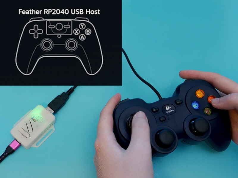
Save your thumbs with a turbo button
dusky agate
heavy hedge
I found a way to use modern gamepads with the USB host on the Fruit Jam! https:/...
ah will need to check that
i've got some i2s sound stuff going using either headphone or internal speaker or both at same time. I did had to ask a lot of help from claude.ai for this
i can upload a sample to github if you like
dusky agate
heavy hedge
I found a way to use modern gamepads with the USB host on the Fruit Jam! https:/...
thats basically what i do also i did you test with your controllers ?
heavy hedge
dusky agate
thats basically what i do also i did you test with your controllers ?
Yeah, It was able to detect the Pro Controller as being made by Nintendo but nothing else
dusky agate
heavy hedge
Yeah, It was able to detect the Pro Controller as being made by Nintendo but not...
yeah thats normal i can do that also
it's just grabbing that from hid info
but it probably can't read out the values
how the linked article reads joypad state is exactly how i do it
and the modern controllers don't seem todo it that way
you should check if it's sending them report values
btw do you need the sound sample ? its a lib / functions i needed so i could play multiple tones of multiple frequencies at the same time potentially sheduled to play in the future the normal tone function is not ok for that as it blocked execution it uses i2s
 fiery furnace
Hello, i am working on my finnal highschool project and i am stuck on working with a stepper motor. So basically i have s nema 17 stepper motor 42x42x23 i think and i am working with a DRV8825 A4988 drvier. The problem is that the connector on the driver does not match the pins on the stepper motor and i tried multiple ways of connecting it with jumper wires i checked the coil pairs with a multimeter. After connecting the most i got to is that the motor was shaking or that when trying to spin the shaft by hand its harder then normally but still manageable.
leaden walrus
can you post some photos of what you got?
fiery furnace
leaden walrus
can you post some photos of what you got?
Hello
Thank you for replying

This is my setup
DRV8825 A4988 driver, esp32 and the nema 17, not the same as in the description thoe since i am testing with multiple
to basically i have pin 4 for direction, 13 for step and 5 as enabled
also have a common ground for the driver and esp
leaden walrus
do you have a link to a product page for this?
 fiery furnace
is this what you meant?
like where i ordered it, cous i got it from ali express. and then followed a yt tutoria, but one if the issues alredy was that the port pins on the driver dont match the ones on the motor
leaden walrus
looks like the bottom board is just a carrier board
and purple board is DRV8825
how did you figure out the orientation for the purple board?
fiery furnace
the pins are named under the board. so i basically orientated the side that takes motor pins to the motor and the one that takes the commands from the esp to the other side
 fiery furnace
leaden walrus
did the purple board have vin labeled?
fiery furnace
leaden walrus
did the purple board have vin labeled?
it did yes
 fiery furnace
5V
leaden walrus
it'd be worth re-working the soldering on this pin

and any others in a similar state
fiery furnace
i didnt even notice that
but i am not sure if that is the problem since i used 2 different drives of same cinde and the other one had the same results but looks to be solderd alright
 echo merlin
Hey! I want to make this ultrasonic levitator and i bought 9 of the HC-SR04 boards from a local reseller which here in albania cost a lot. but i am now finding out that from those boards you can only take one of the sensors because one is a transmitter and one is a reciever and this project only uses transmittors. Do i need to buy 9 more or can i use the 9 that came with the boards?
I was reading this
https://www.instructables.com/Making-an-Acoustic-Levitator-or-Ultrasonic-Levitat/
Specifically,
"As you extract the two components from the sensor module, you'll uncover one transducer and one receiver. Despite their similar appearance, they serve distinct purposes. Our focus for this project lies solely on the transducers, responsible for generating sound waves, not receiving or sensing them."

Instructables
Making an Acoustic Levitator or Ultrasonic Levitation: So, I wanted to try something cool with my ultrasonic sensors. I've already done projects like obstacle-avoiding cars and water level indicators before, but this time I was after something different. Then, I remembered reading about acoustic levitat…
sharp turret
echo merlin
Hey! I want to make this ultrasonic levitator and i bought 9 of the HC-SR04 boar...
If you need 9 transducers then you need 9 HC-SR04 boards.
echo merlin
sharp turret
If you need 9 transducers then you need 9 HC-SR04 boards.
Yeah but that's what im saying. I'm not sure if i do need 9 transducers
And this project uses 18 sensors so
sharp turret
echo merlin
And this project uses 18 sensors so
You need Qty (18) of the HC-SR04 boards to get 18 transducers.
 echo merlin
sharp turret
You need Qty (18) of the HC-SR04 boards to get 18 transducers.
echo merlin
sharp turret
You need Qty (18) of the HC-SR04 boards to get 18 transducers.
oh man so i need to spent a lot more money
jesus christ another 40$ down the grain
drain
 ebon palm
hi adafruit friends :> is there any pre made software i can install to turn an atmega328p into a seesaw-style gpio/port expander so i dont have to write it myself
i know that you can turn any attiny into a seesaw but what about atmega.
heavy hedge
ebon palm
hi adafruit friends :> is there any pre made software i can install to turn an ...
Arduino might be a possible option

A STEMMA QT to ... whatever! interface.
dusk orchid
ebon palm
hi adafruit friends :> is there any pre made software i can install to turn an ...
There's something more modern than firmata, but I've used that in the past. What's the host going to be?
ebon palm
heavy hedge
https://learn.adafruit.com/adafruit-attiny817-seesaw/arduino
i think this is the host library to talk to a seesaw rather than the code *for* the seesaw.
ebon palm
dusk orchid
There's something more modern than firmata, but I've used that in the past. What...
oh ive never heard of that ! the host is an ESP32 connected over i2c
heavy hedge
ebon palm
oh ive never heard of that ! the host is an ESP32 connected over i2c
Firmata is a way to control Arduino and similar devices using Python
ebon palm
heavy hedge
Firmata is a way to control Arduino and similar devices using Python
i dont think itll work because i need to control it over i2c from another microcontroller rather than over usb with a computer
dusky agate
i'm still having issues with usbhost from adafruit tinyusb disconnecting after a while in the fruitjam port of crisp game library, sometimes it runs many hours without an issue sometimes it disconnects after like 5 minutes. The green leds on the pcb from connected devices turn of and the game no longer receives input from usb connected devices. What i also noticed is that sound stops functioning sometimes as well when this happens. I use i2s sound to play mixed tones at same time. the odd thing is the sound runs in a timer mainly normally on 2nd core along with graphics while the usbhost stuff hast the 1st core all to itself. I have a delay of 100 microseconds in that tight loop besides usbhost task update function. The thing is the controls on the fruitjam still work and the game plays when this happens. So not sure if usbhost is crashing the core somehow and why sound stops functioning that is being played with a timer (so i guess an intterupt). I had already found out spamming the serial connection with messages at high speed could disconnect it but i'm clueless as what might be the cause of this. As far as i can tell i'm not doing anything exotic. So if anyone could shed some insight on where to look or what might be causing it that be great
dusk orchid
ebon palm
i dont think itll work because i need to control it over i2c from another microc...
Ah, yeah firmata traditionally goes over UART, but can be controlled by anything [not just a pc].
Is UART an option instead of i2c?
The newest micropython allows creating an I2CTarget, basically an i2c device, so there might be an option although the atmega328 is probably too small for micropython.
Last resort, you could probably point an LLM/AI at the seesaw firmware repository on GitHub and ask it to port the code from the ATTiny to the Atmega328P, the code is very hardware specific, but the larger atmega should be similar enough that it'll be adaptable.
dusk orchid
🆕 🆕 🆕 BLE just got added to the arduino-pico core: https://github.com/earlephilhower/arduino-pico/releases/tag/5.5.0
dusky agate
thats cool
dusk orchid
dusky agate
i'm still having issues with usbhost from adafruit tinyusb disconnecting after a...
Is this arduino and not circuitpython? If so then there may need to be a smaller recreation example, or just stick the whole code (mentioning library + BSP versions) into an issue on Adafruit TinyUSB repository on github, but don't expect a reply very soon. Another place to seek advice is the forums...
dusky agate
dusk orchid
Is this arduino and not circuitpython? If so then there may need to be a smaller...
yeah this was arduino am still trying things but will do if i keep hitting my head and find nothing
ebon palm
dusk orchid
Ah, yeah firmata traditionally goes over UART, but can be controlled by anything...
unfortunately the board is already connected via i2c (its not my hardware im just rewriting the firmware) and it looks like theres no {micro,circuit}python for any AVR chips
dusk orchid
No circuitpython for avr no, but you can get the circuit/micropython device to interact with the AVR chip (even if it's running arduino code etc), assuming they both behave normally with I2C.
ebon palm
yep but i need the firmware on the client device side that does what i want
i was hoping there was something seesawlike to make it easy so i could do as much work in python as possible
i can explain further. i have a keypad matrix on the avr side and its talking over i2c to the esp32 side, so basically the avr is acting as the keypad controller
if it could just read events and queue them up to be sent out over i2c just like the circuitpython keypad module then that would be perfect
seems like ill have to write it myself which isnt so bad :>
dusk orchid
Ah, good to have the context, thanks. Is there a reason the avr is doing the keypad scanning and not the esp32 directly? I assume it's a fixed bit of hardware
ebon palm
fixed bit of hardware but its because the attachment interface mostly exposes the i2c bus. itd also be like 18 pins to route so i get why they didnt
its this from the adafruit shop -> https://www.adafruit.com/product/4176

Get yourself a kit that can do it all! The M5Stack FACES Pocket Computer is a ESP32-based 3-in-1 pack with swappable keyboard / Gaming / calculator panels! Each panel can be upgraded through ...
and i'm rewriting the firmware on the keyboard which thankfully is open source
dusk orchid
ebon palm
its this from the adafruit shop -> https://www.adafruit.com/product/4176
Oh interesting product. I see what you mean now, the 3 attachable panels use ATmega328p's onboard, then communicate via i2c to the esp32.
It looks like this is the exact firmware/sketch running on the keypad panel, and there was some talk of it being served over 0x08:
https://github.com/m5stack/FACES-Firmware and then presumably your esp32 would use M5Unified to access the boards i2c etc more easily.
There are probably some older examples kicking around, or you might be better asking on the m5stack forum / support email / AI-support
ebon palm
yep i looked at the keypad firmware and i can already talk to it from circuitpython but its a little incomplete, which is why i want something more!
it can only register keyup events, it handles shift/alt/sym and everything for you instead of letting me translate the keys on the esp32
i want literally just the most basic events sent over so i can do everything
there was no circuitpython build for this "m5grey" unit so i built my own. i dont want to reintroduce their special code
dusk orchid
Ah, I see now, good work! Yeah extending the keypad sketch / firmware might be easiest. I decided to go on a little journey porting the seesaw_peripheral repository instead, I'm a bit of a sucker for punishment, but these days with half-decent LLMs it's possibly just a quick punt away.
ebon palm
i dont use LLMs for software at all so thats a little out of my zone
i looked at tweaking their keypad script but its just so weird the way they wrote it
ebon palm
i didnt even know you could change the state of pins by setting PORT# variables
dusk orchid
That's the funny direct-register-access variables which directly manipulate GPIOs, PORT# is mainly in AVR, but similar exist in most architectures / arduino-cores.
ebon palm
is that a speed improvement or something ? i mean they write their own code for setting and clearing bits on DDRC/PORTC but that literally seems like exactly what digitalWrite does
dusk orchid
100% speed, and parallelism. i.e. changing bit 1 and 3 of the PORT_A register might alter GPIO 1 and 3, but at the same time. Digitalwrite would do one then the other (seperate clock/cpu cycles at least, possibly an undeterminate amount of time difference between the two GPIOs being toggled)
ebon palm
is it wishful thinking to hope that the compiler would turn two sequential digitalWrites into one instruction
of course that can't always be done
dusk orchid
Sadly it is too optimistic, although I'm sure it would be appreciated if the compiler would optimise such things (maybe a future win).
ebon palm
tragic
maybe there is a arduino equivalent of the circuitpython keypad library which is very convenient
then i get to do less work
dusk orchid
Think there probably is, but I'm not so up-to-date on keypad stuff.
Is that keypad you have a matrix style (the AVR receives rows+columns), or one button per gpio? I need to test this ported seesaw code with something 😂
I guess a basic gpio over seesaw, or neopixel would be a good test.
ebon palm
they have schematics online, it's 10 columns 4 rows
if i had 40 buttons id build it with a normal uno to test
not sure exactly what ill do instead
dusky agate
dusky agate
i'm still having issues with usbhost from adafruit tinyusb disconnecting after a...
i added this
// Simple crash detection - don't try to preserve across resets
volatile bool crashed = false;
volatile uint32_t crash_pc = 0;
volatile uint32_t crash_lr = 0;

extern "C" {
  void exception_handler() {
    uint32_t lr, pc;
    __asm volatile ("mov %0, lr" : "=r" (lr));
    __asm volatile ("mov %0, pc" : "=r" (pc));

    crash_pc = pc;
    crash_lr = lr;
    crashed = true;

    // Try to output immediately
    Serial.printf("\n\n!!! CRASH !!!\n");
    Serial.printf("PC: 0x%08x\n", pc);
    Serial.printf("LR: 0x%08x\n", lr);
    Serial.printf("Time: %lu ms\n", millis());
    Serial.flush();

    pinMode(LED_BUILTIN, OUTPUT);
    for (;;)
    digitalWrite(LED_BUILTIN, (millis() / 500) & 1);

  }

  void isr_hardfault(void) __attribute__ ((alias("exception_handler")));
  void isr_nmi(void) __attribute__ ((alias("exception_handler")));
}
it should give me potentially some more info on where crash might have happened (if it's not stackoverflow or so) but the funny bit is i've been waiting a day and night for it to crash and it has not crashed yet lol go figure 🙂 It is a bit colder today around here but i doubt that got anything todo with it
i also updated arduino-pico boards setup but not sure if the fruitjam board was setup through that and if it was if it might have changed something
ah seems fruitjam indeed uses arduino-pico boards setup so i wonder if it's just a fluke it has been running for so long now or if it changed something for the better that prevent the crashes now
i did see this but not sure it could be related

i'll leave it running somewhat longer
dusky agate
btw it still has not crashed i'm really starting to think latest arduino pico changed something that fixed it. I might downgrade to previous version just to verify if it would crash again but it's been running like 3 days or so without issues
dusk orchid
ebon palm
not sure exactly what ill do instead
Okay, can't promise much, I haven't got a keypad matrix to test it with yet (nxt week), but I've got claude to port the seesaw firmware to atmega328p: https://github.com/tyeth/Adafruit_seesawPeripheral/tree/pimoroni-circuitpython-example (somehow my fork was 105commits behind 🤦 so will sort that soon too).
I've told the llm to expand the rest of the seesaw device type firmware/sketches (examples folder) with atmega328 ones, and it's added the m5stack faces keypad example too (but uses an alternative i2c address so adjust it to use the commented out one instead if you want it compatible with original esp32 firmware). There's a gpio example for the avr328 which I've tested on pin D5. Also tested Neopixel one (D5). I'll get around to testing the rest eventually.
Admittedly I tested them using circuitpython seesaw code (on an RP2350) to interact over i2c with the atmega328p Arduino Uno board, but same on arduino-esp32 to avr.
ebon palm
dusk orchid
Okay, can't promise much, I haven't got a keypad matrix to test it with yet (nxt...
hi! i havent taken a look at this yet but i did think of one problem with this approach recently.. because the seesaw on the circuitpython side wont be exposed as actual pins, i dont think ill be able to use the keypad library from the esp32 side which would make the interface more difficult. this made me think i might need specialized keypad firmware on the atmega side anyways
dusk orchid
ebon palm
hi! i havent taken a look at this yet but i did think of one problem with this ...
I think there might be some confusion. You would want specialised firmware [seesaw peripheral https://github.com/tyeth/Adafruit_seesawPeripheral_atmega328p/blob/pimoroni-circuitpython-example/examples/example_m5stack_faces_keyboard/example_m5stack_faces_keyboard.ino] running on the atmega side, then the esp32 side would be Arduino [or circuitpython] and use the host side Adafruit seesaw library [https://github.com/adafruit/Adafruit_Seesaw and guide: https://learn.adafruit.com/adafruit-seesaw-atsamd09-breakout/using-the-seesaw-platform ] to access the i2c keypad seesaw peripheral device. The extra interrupt pin should also be supportable.
If you want to leave the keypad firmware untouched then there's libraries from m5stack that would show you the communication methods. [The faces firmware repo is still up although maybe needs older version of m5unified library https://github.com/m5stack/FACES-Firmware/blob/master/KeyBoard.ino ]
Take a look at the neotrelis related examples, it's buttons and neopixels on a seesaw peripheral, treated as a keypad
ebon palm
dusk orchid
I think there might be some confusion. You would want specialised firmware [sees...
i understand all of this, my point is that the circuitpython-side keypad library wants actual board pins rather than the pins as exposed by the seesaw host library. unless the seesaw itself has a keypad peripheral?
dusk orchid
ebon palm
i understand all of this, my point is that the circuitpython-side keypad library...
I've not tried it yet, but believe there is a seesaw compatible keypad class too. https://seesaw.readthedocs.io/en/latest/_modules/adafruit_seesaw/keypad.html
ebon palm
oh okay awesome!
dusk orchid
ebon palm
oh okay awesome!
Okay, had a play tonight, the 3x4 matrix works, with an arduino nano (so tried an uno and nano now). not sure if I should point you at the gpio scanning version, or the branch where I've added matrix support to the main library. Both work okay (best to uncomment CONFIG_UART_DEBUG define to see logging from atmega328p). Mostly just watched the seesaw peripheral device's logs to see if working, but tested on circuitpython seesaw keypad at the end. Be careful about not powering boards twice (usb + stemmaQT): I'd forgotten that nano boards want 4-5volts minimum usually, but if you clock them slower (8MHz instead of 16MHz) then they can run at as low as 2.7volts, so mines now powered by QT (to 5V pin 4th along on nano, not VIN). You'll probably need to modify the examples a bit, so good luck!
 ebon palm
dusk orchid
Okay, had a play tonight, the 3x4 matrix works, with an arduino nano (so tried a...
ebon palm
dusk orchid
Okay, had a play tonight, the 3x4 matrix works, with an arduino nano (so tried a...
thats wonderful!! thank you so much for taking a look at this!!!
ill see if i can get it working!
 wary fulcrum
yo yo yo hello guys. I need help.
I am a beginner and I was working on my first project. I am working on a macropad using the SEEED xiao RP2040 microcontroller. I did all the soldering but encountered a problem with the OLED display. I checked connection with a multimeter but for some odd reason, it shows that the VCC and GND for I2C OLED Display Module 0.91 Inch SSD1306 are connected? I tested it on continuity as well as resistance. Is this normal? I did not solder them together. I did connect VCC of OLED to the 3.3 V on the microcontroller with a wire because the trace printed on the PCB went to 5V which is too much for the microcontroller according to SEEED website. So I had to physically cut that trace and I checked the severed connection with the multimeter. Maybe this has something to do with the problem?
 toxic horizon
HI ! I want to connect an appartment bike with arduino and then to chataigne and then to unreal to get the speed of the bike, and get the bike moving 🙂
Anyone has an idea on how feasible this is ? thanks !!
stable forge
toxic horizon
HI ! I want to connect an appartment bike with arduino and then to chataigne an...
Please don't crosspost. I deleted your other post in #general-chat . Are you saying you have a stationary bike trainer and you want to get its speed?
toxic horizon
stable forge
Please don't crosspost. I deleted your other post in <#336571109430263816> . Are...
ah sorry thanks 🙂 my bad
yeah so i have a stationary bike and i'm trying to get the signal from it like get the speed and put it inside unreal
But i want to avoid having to many cables and i need it to be sturdy 🙂
Thanks again
stable forge
it depends on the bike. is there already a speed or cadence signal? How is it reported now? Bluetooth? Wire? Which bike?
leaden walrus
not arduino, but one example project fwiw:
https://learn.adafruit.com/bluetooth-bicycle-speed-cadence-sensor-display-with-clue/overview
toxic horizon
stable forge
it depends on the bike. is there already a speed or cadence signal? How is it re...
i don't have the bike yet 🙂
i guess it would be a simple screen
but i think this is probably hard to send to unreal
toxic horizon
leaden walrus
not arduino, but one example project fwiw:
<https://learn.adafruit.com/bluetooth...
thanks !
toxic horizon
leaden walrus
not arduino, but one example project fwiw:
<https://learn.adafruit.com/bluetooth...
looks amazing for sure
I'd have to see how it would work with sending info to unreal
stable forge
what is your goal in sending it to unreal? What happens at that point?
toxic horizon
the idea is that when you pedal on the real bike it moves your bike forward in unreal
stable forge
what is unreal running on?
toxic horizon
on a pc
north galleon
Trying to get the rp2040 feather to work with the max3421e usb featherwing. Is it not supported, or am I just doing something wrong?
I tried following the example, but I just get a argument exception
specifically when trying to initialize with the following:
Adafruit_USBH_Host USBHost(&SPI, 10, 9);
(I did import wire, spi, and tinyusb)
 pale sentinel
I have had zero luck getting an SD card to work with an alternate SPI port via Sercom on my Feather m0. I'm using a feather m0 wifi (tried with basic proto too, no luck), and the 1.9" ST7789 TFT display. I'm trying to use Sercom3 as the alternate SPI, with SCK on pin 21 (S3.1), MISO on 20 (S3.0), and MOSI on pin 12 (S3.3 alternate). For the life of me, the SD card will not initialize. It works with the default SPI bus and pins, but does not work with the custom assignments I've made.
I need this alternate bus because eventually I'm putting on the USB Host Featherwing, and I know that hogs the default SPI bus, so I need to do it this way. Any help would be appreciated
If I setup a software SPI driver to use those same pins, it initializes. So...I'm at a total loss
#define SPI_DRIVER_SELECT 2

#include <SPI.h>
#include <Adafruit_GFX.h>
#include <Adafruit_ST7789.h>
#include "SdFat.h"
#include "SdFatConfig.h"

#include "wiring_private.h"

//#define SD_HAS_CUSTOM_SPI 1


//Adafruit_USBH_Host USBHost(&SPI, 10, 9);
char barcode[64];
uint8_t barcodeIndex = 0;

#define TFT_SCK 21
#define TFT_MISO 20
#define TFT_MOSI 12
//#define TFT_CS 6
//#define TFT_RST 5
#define TFT_DC A1
#define SD_CS 6

bool sdStart = false;


SdFat32 sd;
SdFile file;

bool ack = false;
bool timerTrig = false;


SPIClass SPI2(&sercom3, TFT_MISO, TFT_SCK, TFT_MOSI, SPI_PAD_3_SCK_1, SERCOM_RX_PAD_0);
SoftSpiDriver<TFT_MISO, TFT_MOSI, TFT_SCK> softSpi;

//Adafruit_ST7789 tft = Adafruit_ST7789(&SPI2, TFT_CS, TFT_DC, TFT_RST);
//Adafruit_ST7789 tft = Adafruit_ST7789(TFT_CS, TFT_DC, TFT_RST);

void setup() {
  Serial.begin(115200);
  while (!Serial) delay(10);  // Wait for Serial to see error messages


  SPI2.begin();

  #define SD_CFG_SPI2 SdSpiConfig(SD_CS, SHARED_SPI, SD_SCK_MHZ(1), &SPI2)
  #define SD_CFG_SOFT SdSpiConfig(SD_CS, SHARED_SPI, SD_SCK_MHZ(1), &softSpi)

  pinPeripheral(TFT_MISO, PIO_SERCOM);
  pinPeripheral(TFT_MOSI, PIO_SERCOM_ALT);
  pinPeripheral(TFT_SCK, PIO_SERCOM);

  bool ok = sd.begin(SdSpiConfig(SD_CS, SHARED_SPI, SD_SCK_MHZ(1), &softSpi));


  pinPeripheral(TFT_MISO, PIO_SERCOM);
  pinPeripheral(TFT_MOSI, PIO_SERCOM_ALT);
  pinPeripheral(TFT_SCK, PIO_SERCOM);

  if (!ok) {
    Serial.println("SD Failed");
      sd.initErrorPrint(&Serial);

  } else {
    Serial.println("SD Success!");

  }
}

void loop() {

}
I'm confused by the code above. The #define SD_CFG_SPI2 and #define SD_CFG_SOFT aren't used anywhere. Then you have
  pinPeripheral(TFT_MISO, PIO_SERCOM);
  pinPeripheral(TFT_MOSI, PIO_SERCOM_ALT);
  pinPeripheral(TFT_SCK, PIO_SERCOM);
twice. Could you clean it up a bit?
pale sentinel
stable forge
I'm confused by the code above. The `#define SD_CFG_SPI2` and `#define SD_CFG_SO...
I apologize, I was testing multiple things at once and didn't clean it up too well for others.
I have narrowed down a reproducable issue to this code:
#include <SPI.h>
#include "SdFat.h"
#include "wiring_private.h"

#define TFT_SCK 13
#define TFT_MISO 12
#define TFT_MOSI 11

#define TFT_DC A1
#define SD_CS 6

SdFat32 sd;
SdFile file;

SPIClass SPI2(&sercom1, TFT_MISO, TFT_SCK, TFT_MOSI, SPI_PAD_0_SCK_1, SERCOM_RX_PAD_3);

void setup() {

  Serial.begin(115200);

  SPI2.begin();
  SdSpiConfig cfg = SdSpiConfig(SD_CS, SHARED_SPI, SD_SCK_MHZ(1), &SPI2);

  pinPeripheral(TFT_MISO, PIO_SERCOM);
  pinPeripheral(TFT_SCK, PIO_SERCOM);
  pinPeripheral(TFT_MOSI, PIO_SERCOM);

  if (!sd.begin(cfg)) {
    Serial.println("SD Failed");
    sd.initErrorPrint(&Serial);
  } else {
    Serial.println("SD Success!");
  }
}
void loop() {
  SPI2.beginTransaction(SPISettings(250000, MSBFIRST, SPI_MODE0));
  SPI2.transfer(0xFF);
  SPI2.endTransaction();
}
I am probing the SCK and MOSI lines with my oscilloscope. The code above does not begin the SPI2 transfer. On my scope all I see are the MOSI and SCK lines going high once, and that's it. No clock signal. If I comment out the if(!sd.begin) block, then I see what you would expect: the SCK and MOSI lines pulsing and doing activity.
I have SdFat 2.3.0 library installed, along with Arduino IDE 2.3.5.
Adafruit Feather m0 + atwinc1500, adafruit 1.9" 170x320 ST7789 TFT display, Lexar SD card. The SD card and accompanying hardware will begin if I use the default SPI bus
SD Failed
begin() failed
Do not reformat the SD.
No card, wrong chip select pin, or wiring error?
SdError: 0X1,0X0
This is the error that shows up on the serial monitor. I"ve also seen 0xFF as an error
stable forge
I'm still confused. Are you using the same MOSI, MISO, and SCK pins for both the display and the SD card socket?
TFT_MOSI, TFT_MISO, and TFT_SCK are connected to both?
pale sentinel
Yes, the SD card socket is attached to the Display. https://learn.adafruit.com/adafruit-1-9-color-ips-tft-display

A nice medium sized display that may be the perfect fit for your project
stable forge
so you shouldn't use a second SERCOM for that, because it's the same pins. Instead, use the same SPI, and just use different CS pins for the two devices (display or SD card)
it is a shared bus. Which device is controlled depends on which CS pin is exercised
pale sentinel
The end goal of this project involves the USB host Featherwing, which uses the default SPI bus, and it kinda hogs it. I haven't been able to get the USB host featherwing, this display, and SD card working together on the same SPI bus
stable forge
this is like I2C, kind of. You use a single Wire object, and the devices on it have different addresses. In this case, the "address" is just the CS pin
so, in this case, you want to use SPI2 for the display + SD card, and the regular SPI for the host featherwing?
pale sentinel
Yes, that would be the goal
I have omitted the display and host featherwing in this code to focus on getting the SD card working. I will introduce those pieces (that have worked individually and together) later. It's just the SD card that's not working on SPI2
stable forge
looking at the sercom assignments...
 pale sentinel
I shall verify
stable forge
does SPI2.begin() return a boolean that you could check?
pale sentinel
#include <SPI.h>

#include "SdFat.h"
#include <Adafruit_GFX.h>
#include <Adafruit_ST7789.h>

#include "wiring_private.h"


#define TFT_SCK 13
#define TFT_MISO 12
#define TFT_MOSI 11
#define TFT_RST A0
#define TFT_DC A1
#define SD_CS 6
#define TFT_CS 5

SdFat32 sd;
SdFile file;

SPIClass SPI2(&sercom1, TFT_MISO, TFT_SCK, TFT_MOSI, SPI_PAD_0_SCK_1, SERCOM_RX_PAD_3);
Adafruit_ST7789 tft = Adafruit_ST7789(&SPI2, TFT_CS, TFT_DC, TFT_RST);
void setup() {

  Serial.begin(115200);

  SPI2.begin();
  SdSpiConfig cfg = SdSpiConfig(SD_CS, SHARED_SPI, SD_SCK_MHZ(1), &SPI2);

  pinPeripheral(TFT_MISO, PIO_SERCOM);
  pinPeripheral(TFT_SCK, PIO_SERCOM);
  pinPeripheral(TFT_MOSI, PIO_SERCOM);
  tft.init(170,320);
  tft.fillScreen(ST77XX_GREEN);

  if (!sd.begin(cfg)) {
    Serial.println("SD Failed");
    sd.initErrorPrint(&Serial);

  } else {
    Serial.println("SD Success!");
  }
}

void loop() {
  SPI2.beginTransaction(SPISettings(250000, MSBFIRST, SPI_MODE0));

  SPI2.transfer(0xFF);

  SPI2.endTransaction();
}
The preceding code (and correct connections) fill the screen Green
And still the same error message for the SD card as before. 0x1, 0x0
And SPI2.begin() is a void, apparently
stable forge
are you using the adafruit SdFat or the greiman one?
pale sentinel
Greiman I think
Multiple libraries were found for "SdFat.h"
  Used: C:\Users\<REDACTED>\Documents\Arduino\libraries\SdFat
  Not used: C:\Users\<REDACTED>\Documents\Arduino\libraries\SdFat_-_Adafruit_Fork
All our Learn Guides say to use our fork of the SdFat library. I'm sorry I'm not familiar with this. There are a number of examples of reading data from an SD card, for instance: https://learn.adafruit.com/adafruit-gfx-graphics-library?
if you used the default SPI, does it all work?
The SD_SCK_MHZ(1) also seems fishy to me (too low), but maybe you picked that up from somewhere.
I would say to search in https://forums.adafruit.com and post there if you can't get it to work
I would put some logging in the sd.begin() operation to see why it is returning false.
pale sentinel
I used the examples for pulling CardInfo with the default SPI, so I am confident that the hardware works correctly. The SD_SCK_MHZ(1) was just something I picked up to help debugging.
Thank you for your help. If I figure it out, can I ping you with the answer, or do you not care?
stable forge
sure, i am interested, and maybe some other Adafruit folks with more arduino experience would have something to contribute
pale sentinel
Thank you. I appreciate your help
spiral granite

Instructables
1.28" LCD Gauges - for NA Miata's and Other Cars.: While searching for some other items these 1.28 round LCDs popped up and I knew when I saw them that they would be perfect for this application. These pop right into place of the OEM NA Miata (89-97) gauges (and probably other cars as well) and…
Guys im trying to build this
0 experience with this
Bought all the parts like the website
Installed everything
But my display just shows nothing
Backlight works but nothing more
Even AI cant help me lol
Im trying the color test code but its not working
Testet multiple cables, ports, pins are soldered good and also messured it
So hardware should be fine
A blink programm for the Seeed itself worked fine
But the display just hates me lol
I was able to get it to work with a 32 dev board, so the display is NOT broken
Its only my brain whos not working lol
pale sentinel
stable forge
sure, i am interested, and maybe some other Adafruit folks with more arduino exp...
I solved it! The SD card (and tft) initialize on an SPI bus made with the SERCOM stuff!!
Working code:
#include <SPI.h>
#include "SdFat.h"
#include <Adafruit_GFX.h>
#include <Adafruit_ST7789.h>
#include "SdFatConfig.h"
#include "wiring_private.h"

#define TFT_SCK 13
#define TFT_MISO 12
#define TFT_MOSI 11
#define TFT_RST A0
#define TFT_DC A1
#define SD_CS 6
#define TFT_CS 5

SdFat32 sd;
SdFile file;

SPIClass mySPI(&sercom1, TFT_MISO, TFT_SCK, TFT_MOSI, SPI_PAD_0_SCK_1, SERCOM_RX_PAD_3);
Adafruit_ST7789 tft = Adafruit_ST7789(&mySPI, TFT_CS, TFT_DC, TFT_RST);
void setup() {
  Serial.begin(115200);

  delay(1000);
  Serial.println("--- Booting ---");


  mySPI.begin();
  Serial.println("SPI Object Initialized");


  pinPeripheral(TFT_MISO, PIO_SERCOM);
  pinPeripheral(TFT_SCK, PIO_SERCOM);
  pinPeripheral(TFT_MOSI, PIO_SERCOM);


  SdSpiConfig cfg = SdSpiConfig(SD_CS, USER_SPI_BEGIN, SD_SCK_HZ(1), &mySPI);

  Serial.println("Calling sd.begin...");
  if (!sd.begin(cfg)) {
    tft.init(170, 320);
    tft.fillScreen(ST77XX_RED);

    Serial.println("SD Init Failed.");
    sd.initErrorPrint(&Serial);
  } else {
    tft.init(170, 320);
    tft.fillScreen(ST77XX_GREEN);
    Serial.println("SD Success!");
  }
}

void loop() {
}
The two key pieces that make this work: The argument USER_SPI_BEGIN, and the delay(1000) . UPER_SPI_BEGIN was apparently the right argument (instead of DEDICATED_SPI or SHARED_SPI), but I can't quite figure out why. The delay(1000) is needed, im not sure why. delay(500) wasn't working, but while(!Serial) was, so I tried 1000 and it worked.
I'm leaving this here for archival purposes and posting a message in my thread. This was so stupid, but it works now!
 meager tinsel
Is it possible to establish communication between two arduino
spiral granite
Is here someone who could help me connect a GC9A01 with a Seeeduino XIAO SAMD21G18
Im following a tutorial with the eSPI libary but my screen just does nothing.....
Also tried Adafruit same problem
The screen worked on a 32dev board so its not broken
stable forge
pale sentinel
I solved it! The SD card (and tft) initialize on an SPI bus made with the SERCOM...
Glad you got it working! The needed delay is mysterious to me. Maybe I can figure something out.
leaden walrus
meager tinsel
Is it possible to establish communication between two arduino
yes. specifics would depend on what you are trying to do.
meager tinsel
i am trying to actually do it between an esp and an arduino
stable forge
meager tinsel
i am trying to actually do it between an esp and an arduino
the easiest way is probably UART. But you may need to do level-shifting, since the ESP is 3.3V and many Arduinos are 5v. You may be able to get away with a voltage divider for the signal going to the ESP and the 3.3V signal to the Arduino may be high enough to be detected by the Arduino. But it could be marginal.
Or, choose some 3.3v board instead of the Arduino
dusk orchid
meager tinsel
and ESP 32?
Raspberry pi Pico 1 / 2, with or without WiFi [rp2040/rp2350 based boards]
pale sentinel
Feather m0 line...
meager tinsel
Ok thx
 abstract marsh
Hello guys, does anyone maybe know why my older purchased nano 3.0 works fine with powering a mlx90614+ display(all on 5v) with a smartphone as power source but the nano i purchased recently make problems. Using the laptop as a power source works. Both nanos have the ch340 chip.
Maybe anyone knows a solution or why this is happening exactly?
Thanks so much in advance!
heavy hedge
abstract marsh
Hello guys, does anyone maybe know why my older purchased nano 3.0 works fine wi...
There are different versions of the chip. Does yours have an external 12MHz crystal oscillator?
abstract marsh
heavy hedge
There are different versions of the chip. Does yours have an external 12MHz crys...
The Webshop says 16mhz for both
But not sure if this is the oscillator you are referring
 teal saffron
Hey y'all, I've been working on an e-ink clock, but keep running into the issue of the display only refreshing every other time. I'm using an ESP32-C6 feather board, e-ink friend featherwing, and 3.7" monochrome thinkink display. I originally tried this on CircuitPython where every other time the display just wouldn't update. I rewrote the program in Arduino hoping it would fix the problem, but now the display refreshes to static every other time. Any takers?
I'm refreshing the display with the current time, then going into deep sleep. The display updates without fail if I use the refresh button on the board.
I've also tried letting the board sleep for 3+ minutes and it still causes the same problem
oblique nova
teal saffron
I've also tried letting the board sleep for 3+ minutes and it still causes the s...
Are you able to reduce the code to a small, reproducible example and share that? I'm guessing it might help anyone looking at it.
teal saffron
#include "Adafruit_ThinkInk.h"
ThinkInk_370_Mono_BAAMFGN display(8, -1, 7, 6, -1, &SPI);
void setup() {
  // DISPLAY UPDATE
  display.begin(THINKINK_MONO);
  display.clearBuffer();
  display.setTextColor(EPD_BLACK);
  display.setTextSize(13);
  display.setCursor(0, 100);
  display.printf("%.2d:%.2d", 0, 0);
  display.display();
  // DEEP SLEEP
  display.powerDown();
  pinMode(NEOPIXEL_I2C_POWER, OUTPUT);
  digitalWrite(NEOPIXEL_I2C_POWER, LOW);
  esp_sleep_enable_timer_wakeup(1000000);
  esp_deep_sleep_start();
}
this is the jist
oblique nova
teal saffron
this is the jist
(I'm not familiar with this display) but fwiw, do you know the power-down behavior of the device? I think the display is being initialized with no reset pin connected (display(8, -1 /*reset*/) - could it be that - once the device is explicitly powered down over spi - the only way it can be woken up is by toggling the reset pin? (Is it currently floating or tied low?)
teal saffron
The thing is that it'll work every other try, which I don't know how it'd wake back up.
teal saffron
oblique nova
(I'm not familiar with this display) but fwiw, do you know the power-down behavi...
I don't know which state it's currently in though
oblique nova
teal saffron
I don't know which state it's currently in though
It's presumably in powerdown mode by the time the esp is put into deep-sleep no?
(My 0.02) might be an easy test to sanity check (assuming you have a spare pin) - if the reset pin is floating, it might eliminate that as a cause. (It might be unpredictable esp. if it's a floating pin)
I guess you can just toggle the reset pin on the display (if you have a handy breadboard), rather than the whole device - that would also triangulate things; but might just be quicker to feed the reset pin to the library so it can correctly toggle it on startup.
teal saffron
Issue is that I don't know the reset pin :/

trying to use this to find the pin, but it seems the top left is the same as the board's pin? which i can't interact with in arduino
oblique nova
I'm assuming you have the feather friend stacked on top of the esp32c6 board at the moment?
teal saffron
yep
i see an EINK_RESET pin in the schematic but I don't understand where it leads
10?
oblique nova
teal saffron
10?
Yes, it's 10 on the eink device. It looks like the reset is hardwired to the mcu's reset, so it might be a bit trick to separate the two resets I'm cguessing; but someone more knowledgable about featherwings will chime in I'm sure. For the moment, I suppose the easist thing might be to just not powerdown() the display no? Likely it'll be in a pretty low consuming state. (You should be able to continue putting the esp into deep-sleep as usual.)
teal saffron
I'll try not powering down and see if it helps
oblique nova
teal saffron
I'll try not powering down and see if it helps
That'll be a great check on the theory 👍 - I see there's a jumper (SJ5) you can remove to disconnect the two resets; but I like your plan to check the assumptions first
teal saffron
the jumper would definitely be more last-resort. I still don't understand why it'd still work, just only every other time
like consistently every other time
for a while i was using the clock anyways and it'd just display the even minutes which tbh wasn't so bad. it just ain't right
and theoretically i could just have the display update every 30 seconds and it'd work fine, but again it just ain't right
oblique nova
teal saffron
for a while i was using the clock anyways and it'd just display the even minutes...
It's annoying to have a mystery bug 😉 completely understand
teal saffron
especially on such a simple project lol
oblique nova
teal saffron
especially on such a simple project lol
maybe to do with the deep sleep + powerdown (I didn't see any examples on the github repo that exercised this part of the device but maybe I'm missing it.) Do you think it would be simpler/more power-friendly to just use the breakout (rather than the friend) for the clock application? 🙂 good luck with it!
teal saffron
oblique nova
maybe to do with the deep sleep + powerdown (I didn't see any examples on the gi...
thanks! i do like how simple it is right now, so i'm gonna try to see if it can be resolved in code.
heavy hedge
abstract marsh
The Webshop says 16mhz for both
No, I don’t mean the one for the processor itself (16MHz)
 mint laurel
oblique nova
Yes, it's 10 on the eink device. It looks like the reset is hardwired to the mcu...
mint laurel
oblique nova
Yes, it's 10 on the eink device. It looks like the reset is hardwired to the mcu...
Just for the record, I've modified 2 of my Eink Feather Friends to isolate the EPD reset. First you cut the tiny trace linking the two pads marked reset. Then you solder a small wire to the pad toward the center of the board. The pad next to the reset pin itself is the side tied to the microcontroller reset and the pad closer to the middle of the feather friend is the one tied to the EPD display ribbon's reset. There are a few controllers like UC8151D that aren't very happy with a simulated/timed reset.
 errant locust
need some advice on an arduino/platformio issue... running a esp32-s3 tft feather; only thing in the code is in setup():
  while (!Serial)
    ;
  Serial.println(F("Starting"));```
but after uploading, I don't see anything at all in the monitor.i was working on a project that I set aside a couple weeks ago, that did work at the time, but now has the same 'no serial monitor' issue.
errant locust
nevermind, swapped to another feather and it works fine. guess that one has issues.
abstract marsh
heavy hedge
No, I don’t mean the one for the processor itself (16MHz)
Oh okay. The old one and the new one seem to have that part on the board (But not sure if it's 12mhz).
The only difference I found is, that the new one has atimel on the chip and the older one has no visible writing on it
heavy hedge
abstract marsh
Oh okay. The old one and the new one seem to have that part on the board (But no...
They could be different generations of Atmel microcontrollers
abstract marsh
heavy hedge
They could be different generations of Atmel microcontrollers
I'll see if I can find out more. Can't sleep or eat before I have solved that problem. I'm afraid to say I have just a very small time frame left to survive 😂
 obtuse mist
Hi folks! I'm not sure if this is really an Arduino problem, but I'm having trouble replacing the bootloader on a device & I'm trying it through Arduino & NRF Connect with no luck. Is anyone a pro on this part?
This device is a Raytac MDBT50Q-CX which is an NRF52840 dongle, but the Type-C one, not the Type-A that Adafruit sells. Here's a link https://www.amazon.com/dp/B0DP6MVDZQ?ref=ppx_yo2ov_dt_b_fed_asin_title It's the perfect part for an AT project in Pinellas County, but only if I can get HID-Remapper running on it.
So, I grabbed the bootloader for the Type-A board and tried to load it, but the device won't seem to let me write it - under Arduino I get "port not open" and under NRF-Connect I get one of several errors
I've tried "holding the button while pluggin it in" and I've so-far gotten blinking blue, solid blue, and black (no led) modes. I've not gotten to the "pulsing red" mode that Gemini seems to think I should get. Anyone have any ideas?

Nordic nRF52840 SoC solution dongle Type C USB Interface Open Bootloader pre-loaded Not plug & play but need firmware loaded before used it Find article " User Manual of MDBT50Q-CX (nRF52840/nRF52833-based USB-C Dongle)" for introduction Find article " Transition tips for program from MDBT50Q-RX ...
obtuse mist
I've tried these instructions to load the Adafruit bootloader with no luck https://raytac.blog/2024/07/10/firmware-coding-dfu-onto-mdbt50q-rxuser-manual-of-mdbt50q-cx-nrf52840-usb-c-dongle/

MDBT50Q-CX is an advanced version of Raytac’s MDBT50Q-R…
stable forge
obtuse mist
I've tried these instructions to load the Adafruit bootloader with no luck https...
Try the instructions here instead: https://github.com/adafruit/Adafruit_nRF52_Bootloader
https://www.adafruit.com/product/5199 has the UF2 bootloader already installed

This USB dongle/key type thing is a little unusual - it isn't a Bluetooth® Low Energy adapter that you plug into a computer to add wireless capability. (If you do want something like ...
 brave sluice
Community:
I have recently purchased an Adafruit Fruit Jam.
I am trying to play an MP# file through the TVL320DAC3100 using the Adafruit_MP3.h library,
but when I go to build I keep getting the folowing error:
In file included from C:\******************************************************************/Adafruit_MP3.h:10,
                 from C:\****************************************\.arduinoIDE-unsaved2026116-23740-385pte.637at\DMA_play_from_SD\DMA_play_from_SD.ino:4:
c:\Users\Rell W. Ambrose\Documents\Arduino\libraries\Adafruit_MP3\src/arm_math.h:347:4: error: #error "Define according the used Cortex core ARM_MATH_CM7, ARM_MATH_CM4, ARM_MATH_CM3, ARM_MATH_CM0PLUS, ARM_MATH_CM0, ARM_MATH_ARMV8MBL, ARM_MATH_ARMV8MML"
  347 |   #error "Define according the used Cortex core ARM_MATH_CM7, ARM_MATH_CM4, ARM_MATH_CM3, ARM_MATH_CM0PLUS, ARM_MATH_CM0, ARM_MATH_ARMV8MBL, ARM_MATH_ARMV8MML"
      |    ^~~~~
exit status 1

Compilation error: exit status 1
Has anyone managed to get the Adafruit_MP3.h library working with the Adafruit Fruit Jam?
obtuse mist
stable forge
https://www.adafruit.com/product/5199 has the UF2 bootloader already installed
Yes, and I am sure if Adafruit sold the USB-C version they'd make it UF2 compatible. But right now they don't and I need this to work on an iPad (ideally without an adapter). I'm learning alot about NRF soft devices, but I'm not there yet. Right now, there's a project to make Open DFU-compatible .hex files on HID Remapper (Github). Those .hex files load via nrfutil and work(ish). They show up in the Web Config, but they overwrite the SoftDevice on the dongle and they don't have their own SoftDevice (or BT stack of any kind). So... that sucks
obtuse mist
obtuse mist
Yes, and I am sure if Adafruit sold the USB-C version they'd make it UF2 compati...
FYI: I was able to get this working. There's a fork (and a pending PR) on building hid-remapper for the stock DFU bootloader that ships from Nordic. With just a few changes, I was able to get this board working (yay). It took way longer than I would have hoped, but I learned a ton about the ridiculous Zephyr build environment!
heavy hedge
Are there step-by-step directions to getting Arduino running on the NeoTrellis M4 Express? Mine keeps failing to upload (Audio portion)
It gets stuck on InterfaceDescriptor
UPDATE: I switched the USB stack to Arduino and that fixed it!
 granite sand
i wasn't sure where the best place to put this was, but does anybody know the status of the Bluefruit Connect app for Android? Seems you can still get it on the iOS store but it is no longer available for download on the Play store (a bunch of students in my class with current and prior versions of android are finding that it is not available). weirdly i can install it because i transferred my settings, but the install option is grayed out for them
(we solved with just using a different bluetooth serial app, but obviously that's a bit more limited than what's available)
 heavy hedge
granite sand
i wasn't sure where the best place to put this was, but does anybody know the st...
heavy hedge
granite sand
i wasn't sure where the best place to put this was, but does anybody know the st...
I think the app is still in development
granite sand
heavy hedge
I think the app is still in development
ah ok, found the git repo. i'll log an issue there
https://github.com/adafruit/Bluefruit_LE_Connect_v2/issues/66

GitHub
App doesn't seem to be currently available for new installations from the Play store. I was able to install it since I had transferred my apps from an old phone (and can install via the Play st...
 iron granite
granite sand
i wasn't sure where the best place to put this was, but does anybody know the st...
iron granite
granite sand
i wasn't sure where the best place to put this was, but does anybody know the st...
I am working on a new release for the Bluefruit Connect App. We are re-publishing it under a different play store listing. Hoping ot have it ready soon!
 acoustic inlet
hello! i just got the Adafruit Industries 1.8" Color TFT LCD Display with MicroSD Card Breakout (https://www.microcenter.com/product/613506/adafruit-industries-18-color-tft-lcd-display-with-)
ive soldered and tried to connect them, and it turns on but only shows a white screen. ive tried applying more flux and reflowing the connections as best as i can, but still a white screen.
i got an arduino nano R4 for this, but i have to get a proper cord for it so im using my arduino nano for this. my connections are:
VCC to 5V, GND to GND, RESET to D9, D/C to D8, CARD_CS to D10, TFT_CS to D4, MOSI to D11, SCK to D13, MISO to D12 and LITE to 5V
any advice?
 stable forge
acoustic inlet
hello! i just got the Adafruit Industries 1.8" Color TFT LCD Display with Micro...
stable forge
acoustic inlet
hello! i just got the Adafruit Industries 1.8" Color TFT LCD Display with Micro...
I assume you're using some standard test program? triple-checkt t wiring, and if you still have trouble, you can open a thread in https://forums.adafruit.com if no one answers. That's the official support mechanism.
acoustic inlet
hello! i was using the official adafruit breakout wiring and used the graphicstest from examples in arduino IDE

im just not sure if my soldering is good enough? im still a beginner solder so im not sure if that could be the issue? i tried reflowing it a bunch though
stable forge
acoustic inlet
im just not sure if my soldering is good enough? im still a beginner solder so i...
your soldering looks ok, though it's a bit blurry and a little hard to see if there are any shorts between pins. Check with a magnifying class if necessary.
YOu could try removing all the wires and re-connecting them one at a time. Were the headers already soldered on the Arduino Nano? (They are soldered, right?)
acoustic inlet
yeah! the nano came with the headers pre soldered on
stable forge
it is most likely this is a wiring error. You could also add print statements in the sketch to make sure it is progressing and has not crashed, etc.


 stable forge
excellent
could also be a pin error in the sketch
have you run sketches on the Nano before successfully?
acoustic inlet
i have! this is a nano from one of my college classes actually, i had just gotten this lcd for a personal project :)
stable forge
btw, the usual convention for power and ground is red for power and black for ground. I was confused at first by your photo
acoustic inlet
oh yes my apologies, ive just stuck various colored jumpers on there haha
stable forge
I don't have time right now to wire this up to check, but I expect the demo to work. It's an old product and the code should work
are you using the parrot demo/
acoustic inlet
no, i was trying to get the demo before that to work actually
but i will try this one quick!

i really appreciate you taking the time to assist me though, any advice is really appreciated
stable forge
doesn't matter, the triangle should work too
are you powering the display with 3.3v or 5v?
acoustic inlet
5V
stable forge
that's fine
acoustic inlet
i tried 3.3V too and didnt do anything different
stable forge
the flux is non-conductive, so it just looks bad
acoustic inlet
i guess when i read the wiring its a bit confusing, like one part says CLK but theres no CLK on my board. do i ignore it?
stable forge
nope, won't work without it
no CLK on the nano or the display?
use SCK for the CLK
I will be afk for a while
acoustic inlet
no worries, thank you! i will try with this oncr again
ah it worked!!!
thank you thank you, it was the wiring after all!!
❤️❤️❤️
stable forge
acoustic inlet
❤️❤️❤️
Glad to hear!
iron granite
@granite sand, @scarlet willow update: the new Bluefruit Connect app is published now: https://play.google.com/store/apps/details?id=com.adafruit.bluefruit.le.connect.v4
granite sand
iron granite
<@413407038484381697>, <@935694081085030430> update: the new Bluefruit Connect a...
thanks! we'll give it a shot
 burnt isle
hey, im trying to communicate with this CO2 sensor using an Arduino Nano Every. since the arduino has 5v logic and the sensor uses 3.3v UART I was thinking about just using a voltage divider on the TX line to the sensor. would that be good enough or no?
https://www.digikey.com/en/products/detail/gas-sensing-solutions-ltd/SPRINTIR-WF-20/9952881
if not i was just gonna do make this pictured level shifter but i wasn't sure which would be better
like are there specific downsides to a fet driven level shifter vs a voltage divider
 oblique nova
burnt isle
hey, im trying to communicate with this CO2 sensor using an Arduino Nano Every. ...
oblique nova
burnt isle
hey, im trying to communicate with this CO2 sensor using an Arduino Nano Every. ...
(just thinking out loud) I'm guessing the sensor is also reporting results - would you need to handle the Rx line as well?
burnt isle
oblique nova
(just thinking out loud) I'm guessing the sensor is also reporting results - wou...
i was thinking of seeing if the 3.3v would register as high for the 5v voltage on the arduino
i was also wondering if this would work for the level shifter or not
 oblique nova
burnt isle
i was thinking of seeing if the 3.3v would register as high for the 5v voltage o...
oblique nova
burnt isle
i was thinking of seeing if the 3.3v would register as high for the 5v voltage o...
(at least on the divider vs level shifter) tx could work if it's not too high speed (one gotcha at higher might be stray capacitance causing slow rise times if one makes the R very high.)
Rx might be unpredictable at 3.3.
burnt isle
oblique nova
(at least on the divider vs level shifter) tx could work if it's not too high sp...
do you know how to fix the schematic for the level shifter i shared
it's clearly not working but im not sure how to fix it
it's based off the one i sent but it seems like the body diode in the fet will just short the 5v to 3.3v in the bottom one
oblique nova
burnt isle
it's based off the one i sent but it seems like the body diode in the fet will j...
Should the gate connect to the low (3v) side as well on the bottom one?
 hardy gull
oblique nova
Should the gate connect to the low (3v) side as well on the bottom one?
hardy gull
oblique nova
Should the gate connect to the low (3v) side as well on the bottom one?
Yes. And flip the transistor left/right too so the body diode is oriented correctly
burnt isle
hardy gull
Yes. And flip the transistor left/right too so the body diode is oriented correc...
this better?

still getting 3.9v with that upper input grounded which is weird
hardy gull
No, M1 is still facing the wrong way
What transistor are you modeling with? You need a threshold voltage between 1.7 and 3.3v. 2n7000 won’t cut it
stable forge
no, those don't have enough columns. Bend the pins back carefully and get at least a 1/2-size breadboard, like https://www.adafruit.com/product/5422 (which has nice markings corresponding to the Pi Pico), Or https://www.adafruit.com/product/64

It can be tricky to work out which pin is which when the Raspberry Pi Pico is attached to solderless breadboard. Luckily, the MonkMakes Breadboard for Pico solves this problem by labeling ...

This is a cute, half-size breadboard with 400 tie points, good for small projects. It's 3.25" x 2.2" / 8.3cm x 5.5cm with a standard double-strip in the middle ...
https://www.adafruit.com/product/239 is not much more and is twice as wide. The "Premium" ones have better spring clips, making insertion and removal easier.

This is a 'full-size' premium quality breadboard, 830 tie points. Good for small and medium projects. It's 2.2" x 7" (5.5 cm x 17 cm) with a standard double-strip in ...
 umbral holly
stable forge
https://www.adafruit.com/product/239 is not much more and is twice as wide. The ...
umbral holly
stable forge
https://www.adafruit.com/product/239 is not much more and is twice as wide. The ...
Oh okay thanks for this fast answer!!
umbral holly
I actually managed to get it in but I‘m still not sure if this is good enough to make my project properly work
 stable forge
umbral holly
I actually managed to get it in but I‘m still not sure if this is good enough to...
stable forge
umbral holly
I actually managed to get it in but I‘m still not sure if this is good enough to...
If you aren't using the pins that you had to bend, no problem, though it's painful for me to see that.
inland gorge
stable forge
If you aren't using the pins that you had to bend, no problem, though it's painf...
hey at least it's not hacksawing off the end of the Pico like @heady sparrow once did! https://www.hackster.io/news/phillip-burgess-hacks-a-raspberry-pi-pico-down-to-size-literally-sawing-off-the-bottom-quarter-d8478eecfb49

Hackster.io
If the Raspberry Pi Pico's just a little bit too big for your project, this literal hack drops the size by 30 percent — just add saw.
umbral holly
I fixed it now sorry for being such a noob guys
 devout panther
Question for the community:
We have an old keyboard piano. The power supply failed on it, but the other things should still function.
Goal: Mod it with a microcontroller to detect input, and a Raspberry Pi to act as synth
But I'm having trouble with part 1: Detecting inputs
It uses 2 arrays for each side of the keyboard. The left array uses a 16 wires that are charlieplexed somehow. The right array uses a 17 wires.
Each key has 2 inputs. Depending on the difference in time between each switch being depressed.
I wrote a quick bit of code to turn 1 OUTPUT on at a time and cycle through the inputs to see if pressing a key connects the charlieplex to activate the key. But most of what I'm seeing is very noisy and doesn't seem to actually track well to what i am pressing. I was wondering if any of the community may have experience with this?
I am using an Arduino Mega due to the number of pins required.
I believe the original piano used PULLDOWN resistor banks, but the Arduino Mega has PULLUP resistors, so I made the code so that the default ON state is LOW, so that the OUTPUT is pulled LOW when switched and then pulled UP when not switched

I didn't detect any shorts in the soldering connections when I ran a multimeter across them, so I think I did a decent job there
devout panther
I ran an initial sweep with no pins set to OUTPUT, pure INPUT_PULLUP, and got these values:
 devout panther
If I had to guess, some pins are automatically set HIGH and LOW due to the diodes consuming some power.
Since the pins are all set to INPUT_PULLUP, I would normally expect them to all be set to 1 if no inputs are applied, but half are being pulled down somehow.
Is the only way to fix this to connect all these diodes to PULLDOWN resistors?
devout panther
I found a piece of code that uses the arduino Keypad library, I'll take a look at that. I figure if I use that with th ese initial readings, I might be able to finagle my way to success
https://github.com/diyelectromusic/sdemp/tree/main/src/SDEMP/KeyboardMIDIMatrixDecode

GitHub
Simple DIY Electronic Music Projects. Contribute to diyelectromusic/sdemp development by creating an account on GitHub.
 iron kraken
hi,
Working on a simple web server using WiFiManager and hitting an issue with a XIAO ESP32-S3 Sense.
Behavior:
- WiFiManager blocks ~60s, then fails
- No AP is spawned after failure
- Same firmware works fine on another ESP32-S3 board
What I’ve tried:
- Removed camera module
- Switched to external power
No change in behavior
At this point it looks board-specific. (works on other ESP32S3)
Any suggestions on how to debug this further?
untold depot
How do I make the TLV320DAC3100 I2S DAC output via headphones? I tried the example sine output code (https://learn.adafruit.com/adafruit-tlv320dac3100-i2s-dac/arduino) but it is not making any noise through the headphone port. I added code to reset the DAC since I think the author of the tutorial forgot to do that, and I set codec.enableSpeaker(false). I checked the arduino docs but there is no codec.enableHeadphone(bool), despite the CircuitPython code having such a feature.
heavy hedge
untold depot
How do I make the TLV320DAC3100 I2S DAC output via headphones? I tried the examp...
Are you using just the TLV320 or a board with it built in (Fruit Jam)?
untold depot
heavy hedge
Are you using just the TLV320 or a board with it built in (Fruit Jam)?
Just the board with a feather rp2040
heavy hedge
untold depot
Just the board with a feather rp2040
This is for the Fruit Jam but the same logic should still apply:
https://github.com/joyrider3774/crisp-game-lib-portable-fruitjam/blob/main/source/cglpfruitjam/src/i2stones.cpp
https://github.com/joyrider3774/crisp-game-lib-portable-fruitjam/blob/main/source/cglpfruitjam/src/i2stones.h

GitHub
A port of the crisp game lib portable from abagames to the adafruit fruitjam - joyrider3774/crisp-game-lib-portable-fruitjam
GitHub
A port of the crisp game lib portable from abagames to the adafruit fruitjam - joyrider3774/crisp-game-lib-portable-fruitjam
 amber patrol
I need some serious help
Is this
Adafruit Joy FeatherWing for all Feathers
Fully compatible with This
Adafruit KB2040 - RP2040 Kee Boar Driver
To take
The input through Qwiic / STEMMA QT I2C
and output
as a "USB controller" to my system
Without doing any coding
If it isn't what are my options
hardy gull
What do you mean “without any coding”?
I don’t think the kb2040 is a feather
Why not use the Adafruit RP2040 feather?
amber patrol
I'm okay with flashing firmware and stuff like that, but I am not good at coding in the slightest. So if I need to code USB interface or anything like that, it's probably off the table.
I was going to use the Tiny 2350 but it's either out of stock or too expensive from other retailers paying for shipping twice
I meet the microcontroller to be as small as possible and have that I2C port
Also what feather would be best
My project is using a latte panda iota as the motherboard for a handheld batocera machine and I need the controls for it to be split to make it all compact as possible so I need that gamepad x2 and some extra buttons that I'm more than willing to hardwire I know I may have to map the inputs, but I'm fine with doing that as well.
hardy gull
The featherwing literally stacks on top of a feather. Any feather. There’s no point going any smaller than a feather because your minimum footprint is the featherwing. The RP2040 is a good choice because it’s cheap and has a lot of USB endpoints.
However, you do have some control over the height
amber patrol
Well I'm going to be 3d printing a case so I'd be able to configure the boards side by side to make the handheld thinner
amber patrol
If I'm stacking things on top of each other that would be too thich fom the bottom of one board to the top of the other
If I put them side by side in the housing the handheld is only as thick as my thickest port
hardy gull
How are you wiring them? Point to point?
amber patrol
Or periferial
hardy gull
Oh you mean the stemma cables?
amber patrol
Well if its the i2c connector then that
Yeah the stemma qt cables
I have multiplexer to take the two game pads as well
hardy gull
Maybe the qt-py then?
hardy gull
Who cares if it's risc-v? There's a compiler for that
amber patrol
Oh??
hardy gull
Anyway. If you are interested in stacking with a feather, there are low-profile connectors https://www.digikey.com/en/product-highlight/m/millmax/super-low-profile-sockets
Anyway if you want minimal coding, you'll probably have a better time with circuitpython
The USB HID library is super easy to use
amber patrol
Would this work
Adafruit QT Py CH32V203 Dev Board with STEMMA QT
amber patrol
hardy gull
Anyway. If you *are* interested in stacking with a feather, there are low-profil...
That is interesting
hardy gull
There's an even shorter one by Samtec but I forget the name
But 2.1mm is pretty darn short
amber patrol
Well it's either go this route or buy and strip down a phone controller and route the USB internally
amber patrol
hardy gull
But 2.1mm is pretty darn short
Yeah
I'm more of a hardware guy not software
If you can't tell lol
hardy gull
https://suddendocs.samtec.com/catalog_english/sl.pdf Looks like still 2.11mm
So the mill-max ones are a little cheaper
Ahh, I see your concern now
... please note that the CH32 series is not supported nearly-as-well as ATmega, ESP32, ATSAMD, STM32, or RP2040 chips that have a strong company-led development community. WCH is very "its a low cost chip, you figure it out" kind of company, and while there is some community-led development it is still best used by folks comfortable with having to use Makefiles, clone git repositories, edit configuration files, etc. It definitely does not run CircuitPython or Micropython, and Arduino support is very early. It's definitely not good for beginners!
amber patrol
hardy gull
Ahh, I see your concern now
> ... please note that the CH32 series is not suppor...
Yeah
hardy gull
Not sure about the USB endpoints either. Don't think there's a circuitpython build.
amber patrol
I may just have to go with a normal sized feather
hardy gull
Yeah. Go with the rp2040 feather and those low-profile pins. It should be real small once you take the battery connector off the feather
(Don't bother unsoldering, just clip it)
amber patrol
Any advice moving forward?
Also I've never done a project like this I don't know what I would need to do to configure this to essentially work as a USB controller
amber patrol
hardy gull
(Don't bother unsoldering, just clip it)
May just unsolder it for fun and reusability
hardy gull
Yeah. Get circuitpython on your board and try out the HID library. I'm looking for an example that actually does joysticks...
hardy gull
Check it out, there's an example with the Joy Featherwing https://docs.circuitpython.org/projects/hid/en/latest/examples.html#hid-joywing
amber patrol
Oh awesome
 proven scaffold
Hi,
I'm currently trying to connect an Arduino MEGA to both a TSL2561 and a BNO055. They both require the SDA and SCL ports, but when we connect both of them to the circuit, the BNO does not get initialized. They both work properly when connected individually, but when they are both connected, I get the error "BNO055 not found". We've tried specifying each of their addresses, but nothing changed. Any insight on how to fix this would be appreciated.
stable forge
proven scaffold
Hi,
I'm currently trying to connect an Arduino MEGA to both a TSL2561 and a BN...
So they work OK when just one or the other is initialized, but not both?
If you have not tried it already, try initializing the BNO055 first, before the TSL2561
proven scaffold
stable forge
So they work OK when just one or the other is initialized, but not both?
If you ...
that’s right
i believe we’ve already tried doing so
stable forge
proven scaffold
that’s right
are you using 0x39 for the TSL2561 address and 0x29 for the BNO055?
The ADDR pin on the TSL2561 should be left unconnected
proven scaffold
stable forge
are you using 0x39 for the TSL2561 address and 0x29 for the BNO055?
i believe we were using 0x29 and 0x27
we tried printing out the detectable addresses and those two were printed
stable forge
proven scaffold
we tried printing out the detectable addresses and those two were printed
This describes a similar problem https://forums.adafruit.com/viewtopic.php?t=130591 and says the TSL responds to both 0x28 and 0x29, though I'm not sure it's the same problem you are seeing. It also suggests a hack with unequal pullup resistors that improve the behavior of the BNO055. The BNO055 does not adhere to the I2C protocol spec as well as it should.
 empty pecan
Hii!!
Sorry I do not know is this the proper place to describe my problems, please guide me if I am wrong! 🩷
When I am using rotary encoder with my esp32 it jitters , jumps to different menu, whenever I am rotating the knob, meaning it does not work properly. What is the fix for it? Should I use any resistors or capacitors along the lines of my data pins?
Rotary encoder connected via i2c and this is the following code.
Is there something wrong with my code ?
hardy gull
empty pecan
Hii!!
Sorry I do not know is this the proper place to describe my problems, ple...
Yes, the encoder contacts are bouncing. Small capacitors would help - try 0.1uF
inland gorge
empty pecan
Hii!!
Sorry I do not know is this the proper place to describe my problems, ple...
The hardware fix that Marshall suggested is good, and really quick to try.
You may also want to try a rotary encoder library. The one I've used a lot in Arduino is just called "Encoder" by PaulStoffregen. You can find it in the Arduino Library Manager. Not sure if it works with ESP32 but there are other ESP32-specific rotary encoder libraries in the Library Manager (search "esp32 encoder")
 hardy portal
Hey folks,
Recently purchased a MAX17048 battery fuel gage from adafruit, I'm using it on a ESP32 from lilygo, specifically the ESP32 with the A7670G celluar chip. Currently I have SDA wired to GPIO21 and SCL wired to GPIO32. I had SCL wired to 22 previously however the board stopped responding to I2C this morning and i have not been able to get it to respond since.
Heres how everything is wired:
MAX BAT Connector goes to the Battery plus on the ESP32
MAX GND goes to the Battery minus on the esp32
MAX VIN goes to a 3.3v vin on the ESP32
MAX GND goes to a ground on the ESP32
MAX SDA goes to the sda (GPIO 21) on the ESP32
MAX SCL goes to the GPIO 32 on the ESP32
I have tried running an I2C scan script, running the adafruit examples for this and also consulting AI for troubleshooting.
The only thing I can think of is somehow connecting to the battery in parallel with the ESP32 instead of connecting the MAX to the battery then feeding the ESP32 from the MAX directly somehow burnt the board out.
 leaden walrus
how did you do the i2c setup in your scanner sketch?
although it's probably worth trying to figure out why the standard i2c stopped working
hardy portal
this is the i2c scanner i found online whilst looking through forums, also i forgot to mention whilst scl and sda were wired to the 21 and 22 pins on the ESP32 it did communicate fine-ish yesterday. I still saw some errors but i just figured i was initializing I2C before the max could wake up or something
#include <Wire.h>

void setup() {
  Serial.begin(115200);
  delay(500);
  Wire.begin(21, 32);
  Serial.println("Scanning...");
  for (uint8_t addr = 1; addr < 127; addr++) {
    Wire.beginTransmission(addr);
    if (Wire.endTransmission() == 0) {
      Serial.printf("Found device at 0x%02X\n", addr);
    }
  }
  Serial.println("Done.");
}

void loop() {}
tomorrow I'm gonna test the pins with a multimeter and run a sketch to verify I have 3.3v from each
 patent crescent
Hello. I'm trying to get started on a project using the Adafruit Metro RP2350 board. The one that comes with the 8MB PSRAM module pre-installed. I'm wanting to write software for the RISC-V cores to experiment with the special instructions available on the Hazard 3. I've read and it seems I have to use LLVM to do this. I've been Google'ing, reading, trying project generators all day. I even tried AI for help (it got terribly confused due to recent changes in the SDK repos). Does anyone have a blinkin' light example that uses LLVM / Clang?
patent crescent
An example RISC-V Rust project would work also.
inland gorge
patent crescent
Hello. I'm trying to get started on a project using the Adafruit Metro RP2350 bo...
If you’re using the “arduino-pico” philhower core then you can switch to RISC-V architecture in the IDE with Tools->CPU Architecture :
https://arduino-pico.readthedocs.io/en/latest/rp2350.html#arm-and-risc-v-modes
patent crescent
I'm sorry, I'm just having a very hard time getting started with this particular dev board. I'm new to all of this. I tried going to the Adafruit Discord, but one of their rules in the help section says not to ask how to begin, because Google exists (paraphrased). Everything I can find is about the 2040 model. A lot of it is transferable, but the entire build system has been majorly overhauled for the 2350 series if I understand correctly.
patent crescent
OK I just figured out their 2024 doc still applies to the VS Code extension. I'll try that 😄
stable forge
patent crescent
I'm sorry, I'm just having a very hard time getting started with this particular...
I tried going to the Adafruit Discord, but one of their rules in the help section says not to ask how to begin, because Google exists (paraphrased).
This is the adafruit discord. Is there something in #welcome or #code-of-conduct that implies what you wrote? Your interpretation is not what we intended. We do say "don't ask if you can ask something, just ask", but that's designed to encourage you to ask questions.
maybe you meant the Arduino discord?
patent crescent
stable forge
> I tried going to the Adafruit Discord, but one of their rules in the help sect...
Wow, that was embarrassing 😄 I was referring to the Rasperry Pie discord server. I'm not sure if it's official or not? I thought it was but then they started crashing out over politics and @ 'ing everyone. So maybe not?
But I'm up and running with the VS Code Pico extension now. I should be able to get from there to what I need.
Yeah I did some digging and there is not official RP Discord server.
I think I'll leave that one 😄
stable forge
patent crescent
I think I'll leave that one 😄
🙂 https://forums.raspberrypi.com is good
patent crescent
stable forge
🙂 <https://forums.raspberrypi.com> is good
Yeah I read that is the primary way they communicate. I've already gotten some great info there. I'm just trying to decide if I really want to try to learn Rust while I'm wrangling a new environment at the same time 😄
Honestly I don't know much about embedded systems anymore. I used the RPi 2 back in the day, and a bunch of micros on a board type boards.
 woeful river
hi is there a bug with the docs linked from this page on the sidebar ("Arduino Docs"): https://learn.adafruit.com/pmsa003i/arduino
it links to here, but there seems to be no content: https://adafruit.github.io/Adafruit_PM25AQI/html/index.html
leaden walrus
seeing same things. opened a new issue:
https://github.com/adafruit/Adafruit_PM25AQI/issues/20
 hybrid pendant
hey, I was wondering if there is documentation for the Adafruit_ST7735 library explaining how to properly use it with SPI.
stable forge
hybrid pendant
hey, I was wondering if there is documentation for the Adafruit_ST7735 library e...
https://learn.adafruit.com/search?q=st7735 has pages for Arduino in many of the guides.
Also see https://github.com/adafruit/Adafruit-ST7735-Library/tree/master/examples. These examples are directly available in the Arduino IDE.
patent crescent
Where's the best place to get support with pico-sdk? I'm trying to get ARM code compiling with Clang.
hybrid pendant
stable forge
<https://learn.adafruit.com/search?q=st7735> has pages for Arduino in many of th...
thank you
hardy gull
patent crescent
Where's the best place to get support with pico-sdk? I'm trying to get ARM code ...
Raspberry pi forums maybe?
 grave mortar
Hi sorry quick question I haven't worked much with stepper motors, but in declaring a Stepper class the first variable is steps per revolution? How important is the accuracy of this number? I'm unable to find a datasheet for the motor I'm working with.
 ancient elk
hey is anyone active?
stable forge
ancient elk
hey is anyone active?
just ask your question; it will be there when someone is around
hardy gull
grave mortar
Hi sorry quick question I haven't worked much with stepper motors, but in declar...
200 is often correct
Having it wrong will scale the speed and position of your motor
grave mortar
hardy gull
Having it wrong will scale the speed and position of your motor
ah but it won't cause it to just not work eh?
hardy gull
grave mortar
ah but it won't cause it to just not work eh?
Correct. It will still turn
grave mortar
ah okay yeah I think there's just something wrong with the motor then, thanks!
amber patrol
How am I supposed to connect my two joy feather wings to my rp2040 feather with a multiplexer if they (the joy feathers) don't have the i2c connectors
I do see sda and scl but what about the other 2 pins from the connector itself
stable forge
amber patrol
How am I supposed to connect my two joy feather wings to my rp2040 feather with ...
you do not need a multiplexer. The Joy FeatherWings support four different I2C addresses. See https://learn.adafruit.com/joy-featherwing/pinouts#i2c-addressing-2883341. You can connect them to the RP2040 Feather directly. Besides SCL and SDA, you also need to connect 3.3V and GND.
amber patrol
Well I'm making two feather joys connected to a single rp2040 feather to make a USB controller
I'll also be wiring up 6 extra buttons to have all the inputs I need
stable forge
amber patrol
Well I'm making two feather joys connected to a single rp2040 feather to make a ...
since you can solder jumpers to make each feather joy have its own address, then you don't need a multiplexer. You probably have enough extra GPIO pins for the buttons.
 rustic vapor
Hi! I am trying to install the Arduino IDE 2.x on my Chromebook. I have enabled the Linux environment and the distribution seems to be Debian 12.
I've installed FUSE (and I think I managed to make it into an executable using chmod +x), but I now get the error "cannot execute binary file".
Does anyone know what could be wrong?
 hardy gull
What kind of chromebook is it? Arm-based perhaps?
inland gorge
rustic vapor
Hi! I am trying to install the Arduino IDE 2.x on my Chromebook. I have enabled ...
Some Chromebooks are ARM-based and the standard Arduino IDE release is only for Intel (x64)
jinx, @hardy gull ! 🙂
hardy gull
You could build it for ARM. I know the AVR toolchain works on rpi, and I hear that arm-eabi-none might work now too
rustic vapor
Aah! I will google and check. Would that be a big NO on installing the IDE 2.x?
inland gorge
rustic vapor
Hi! I am trying to install the Arduino IDE 2.x on my Chromebook. I have enabled ...
Looks like you may be able to use their Cloud Editor https://support.arduino.cc/hc/en-us/articles/360016495639-Use-Arduino-with-Chromebook
Arduino Help Center
Learn how to write and upload Arduino sketches on Chromebooks running ChromeOS.
In this article:
About Arduino on Chromebook
Optional: Install the Arduino Cloud for Chromebook App
Use the Arduino ...
hardy gull
Tod's solution is surely easier
inland gorge
rustic vapor
Aah! I will google and check. Would that be a big NO on installing the IDE 2.x?
Yes, I think so. If in the terminal you type uname -a and it doesn't say "x86" and says somethng like "aarch64" or "arm64", you've got an ARM Chromebook.
hardy gull
Building GCC on a low-power machine is miserable
rustic vapor
Confirmed "aarch64"!
I was hoping I could use IDE 2.x since the instructions I am using are written using that IDE. I have used the cloud-based IDE, but would prefer to have it local. 🙃
inland gorge
If you are pretty comfortable with commandline, there is the "arduino-cli", a command-line program to do all the stuff the Arduino IDE does (compile, programming, board core downloads, library management) except for editing. There does appear to be Linux ARM downloads for it https://github.com/arduino/arduino-cli/releases
No clue if the Arduino cores you download with it ((that can also be also platform-specific) will work tho
inland gorge
rustic vapor
I was hoping I could use IDE 2.x since the instructions I am using are written u...
yeah local IDE is better, imho too. ARM Chromebooks get much better battery life at least!
rustic vapor
Thanks everyone for the help! I'll sleep on it and make a decision.
(Browsing before sleep, Arduino CLI was a bit s**y...)
stable forge
This could be of interest: https://github.com/matu6968/arduino-ide-arm64. I was unable to find any official ARM builds for debian.
 fervent tartan
Not Arduino but related. Any debugging ideas for this? SMT32f not reconized in com ports other esp32 breakout boards work with same cable and usb port. This one is a few years old I got it in a key board kit as a gift and I just now got around to assembling but am stuck.
 hardy gull
fervent tartan
Not Arduino but related. Any debugging ideas for this? SMT32f not reconized in c...
hardy gull
fervent tartan
Not Arduino but related. Any debugging ideas for this? SMT32f not reconized in c...
Think about what is required for the chip to operate: power, clock, and reset. Check if those are satisfied.
If so, the next step is to try to connect using an STLink debugger. Maybe the USB bootloader isn’t installed? Maybe it’s a faulty chip?
fervent tartan
that what I was starting to think as well. Maybe no bootloader
But also when plugged in no com port or usb device shows up in device manager would this happen just from no boot loader or would that indicate a borked board?
im getting 5.5 v on vdd to ground
hardy gull
That usually indicates no bootloader, but it doesn’t rule out anything
hardy gull
fervent tartan
im getting 5.5 v on vdd to ground
Is this a 5V chip? Measure after the voltage regulator
fervent tartan
that was jus the VDD pin on the outside