#help-with-arduino
1 messages · Page 22 of 1
 sick aspen
 stable forge
sorry, I mean where does it say "dont ever flash firmware on anything but that"
sick aspen
"Do not select any other port than the one that is called "ESP32S2 Dev Module" or "ESP32S3 Dev Module""
https://learn.adafruit.com/adafruit-esp32-s2-feather/using-with-arduino-ide

Make your IoT project fly!
stable forge
it's saying ... in the Port menu don't choose a different board. But in the Board menu choose Feather ESP32-S2
sick aspen
ohhhhh interesting so is this drop down next to the upload button the board or the port?
ohhhhhhhh ok got it
stable forge
which version of arduio are you using?
sick aspen
2.3.4
i can see that the port is selecting dev module even though the board i selected is adafruit feather
stable forge
yeah, sorry, the screenshots are for 1.x.x
yes, the port name is confusing. I will clarify that warning right now.
sick aspen
ok, tried again with the i2c power code in my setup function, it uploaded without errors, but it still isn't finding the encoder
but the green LED on the encoder board is lit now?
stable forge
try the scan sketch that I linked to
sick aspen
ok uploading lets see
device found at 49 which is what the ano is supposed to be, but also 77
i noticed that i dont include wire or wire.begin in my sketch, do you think that might be the issue?
stable forge
0x77 is the battery monitor, which is on the feather board
sick aspen
got it
stable forge
if there's a Wire.begin() in the sample ANO sketch, yes, include that. Do you mean you are not #include'ing Wire? The ANO library .h is probably including that. It woudln't compile without that.
sick aspen
yeah it isn't in the sample ANO sketch
stable forge
the pins are the same
you wouldn't be finding it via the scanner otherwise
could you upload your combined sketch now? You can use the + to the left instead of pasting it inline.
sick aspen
stable forge
still need to add turning the power pin on:
// turn on the I2C power by setting pin to opposite of 'rest state'
  pinMode(PIN_I2C_POWER, INPUT);
  delay(1);
  bool polarity = digitalRead(PIN_I2C_POWER);
  pinMode(PIN_I2C_POWER, OUTPUT);
  digitalWrite(PIN_I2C_POWER, !polarity);
add this before ss.begin()
sick aspen
oh thats right at the top of setup
stable forge
oh sorry, looking at the wrong editor window
so it still says "Couldn't find seesaw on default address"?
sick aspen
umm oddly now I uploaded this exact sketch and im not seeing anything on serial
stable forge
what board name did you select before, OLIMEX ESP32-S2??
sick aspen
always Adafruit Feather ESP32-s2
but noticing that dev module is not appearing on ports now? just Adafruit Feather ESP32-s2 on COM9
stable forge
Partition Schme in the tools menu should be set to "Default 4MB with Spiffs"
stable forge
check the settings there if it still doesn't work. I will be offline for an hour or so, sorry
sick aspen
no no worries I have to go be in the world too but I really appreciate your help 🙂
IT WORKS
LFG
sick aspen
haha, then immediately i tried editing the letter mapping a little and it doesn't work again!! these are my settings. noticing that the dev module is no longer appearing under ports? even when I enter bootloader.
 stable forge
sick aspen
haha, then immediately i tried editing the letter mapping a little and it doesn'...
stable forge
sick aspen
haha, then immediately i tried editing the letter mapping a little and it doesn'...
I think you can ignore looking for the Dev module. Just look for the Feather.
sick aspen
wow, funny, it does seem to be working ! but I didn't change anything.... I think i literally might have just needed to unplug the feather and plug it back in or something?
stable forge
sometimes the port that's needed can change. Not sure what happened here but something may have just been in a wrong state
sick aspen
again really appreciate your help!
 leaden walrus
"dev module" is what it will show as when in ROM bootloader mode
and the i2c power should be enabled by default, so not needed in sketch code. the BSP does it here:
https://github.com/espressif/arduino-esp32/blob/cd7f4218e7fa0d2aa0c736284bf85436e178f361/variants/adafruit_feather_esp32s2/variant.cpp#L31-L43
stable forge
leaden walrus
and the i2c power should be enabled by default, so not needed in sketch code. th...
thanks. should we remove the explicit power enabling in the examples, then (but mention it elsewhere)?
 radiant gulch
Hello, I stumbled upon something interesting with my 2.8 inch TFT (with touch) display.
If I use fillRect from Adafruit_ILI9341 I can draw rectangles (obviously) and see them. But when I unplug and plug the power to my esp32, everything on the screen would render except for the rectangles. But if I were to cut the power, wait for about ~15 seconds and then add power again, everything including the rectangles would render again.
So I'm wondering, does the display needs some off time between restarts? Or could I make a workaround in my code?
but I need to understand what's happening first 🙂
 woeful pike
i tried combinig 2 sketches to use a ds18b20 and a dht11 to send data to adafruit IO. i can compile with no errors and upload. it starts to connect to IO then displays no more addresses. no data to IO, no connection to IO.
what am i missing. im not a programmer by any means. I have the config file with my IO key and password, but I didn't include it here. Does someone see something?
leaden walrus
stable forge
thanks. should we remove the explicit power enabling in the examples, then (but ...
probably, but also safe to leave it. but if the verbiage is "this is required in your user sketch", then yah, that should be updated.
 sharp turret
woeful pike
i tried combinig 2 sketches to use a ds18b20 and a dht11 to send data to adafrui...
sharp turret
woeful pike
i tried combinig 2 sketches to use a ds18b20 and a dht11 to send data to adafrui...
What do you mean by "starts to connect to IO then displays no more addresses"?
woeful pike
sharp turret
What do you mean by "starts to connect to IO then displays no *more* addresses"?
In the serial window output starts
Connecting to AdaFruit IO
Then
No more address continue to pop-up and will run for as long as I leave it plugged in to power.
On a different project Ada IO will showed when data was coming in. Just had a black or blank status bar.
I assume the no more address is from the Dallas onewire sensor because there is a line of code that
sharp turret
woeful pike
In the serial window output starts
Connecting to AdaFruit IO
Then
No more ...
right after the connect call, you print periods until a connection is made and then print the status of the connection. Are you not seeing that either?
woeful pike
It may put some dots up but within a few seconds "no more address" fills up the serial window. It was late last night and didn't think to take pictures or check my network to see if it was on the network. There is a delay of half a second before it starts polling the sensors. Should I make the delay longer?
sharp turret
woeful pike
It may put some dots up but within a few seconds "no more address" fills up the ...
You mean the message “No more addresses.” I took your statement literally.
sharp turret
woeful pike
It may put some dots up but within a few seconds "no more address" fills up the ...
what was the original sketch for you used for the ds18b20?
woeful pike
I started with the AdaFruit sketch for the DHT and there IO. I then took a sketch for I think from them again that did the same thing. I copied the parts for just the Dallas onewire to the sketch I had a few errors for lines not defined. Comment them out. Compiled it then uploaded to a wroom esp32
sharp turret
woeful pike
I started with the AdaFruit sketch for the DHT and there IO. I then took a sket...
do you have the required 4.7k resistor on pin 4?
woeful pike
Yes I am using a ds module
And one for the DHT


ok i tested the hardware with the ds18b20 single and DHTtest sketches both work and put temp data to the serial monitor
woeful pike


i have a some progress the previuous code
i extended a delay and

Now this is what happens it connects to IO then seams to hang repeatedly putting ff off ff at the end of the address.
the code test code is from the library for each sensor
DS18 single example from library
code for DHTtesater from library
code that hangs with FF FF repeating in address.
sharp turret
why are you even bothering to print it in the first place?
woeful pike
Because I am a visual person and my think is if it displays it it the serial monitor, it will be the same on IO.
Also when IO shows no date it's a way for me to see what is going on.
 sharp turret
okay, then, why are you sending the RAM contents to AIO?
woeful pike
I don't think I am. But the code I chose to use for the da 18b20 had it in the sketch. When I start removing code from sketchs I more often than not make it not work, so I tend to copy as much as I can exactly as it was because it work
I don't see where the address is being sent to AIO just the temp data. The address is just being sent to the serial monitor as far as I can tell.
sharp turret
Your code is getting stuck where its reading out the 18b20's RAM contents. So, if you don't need to do that, then why do it?
The example library code is completely different from what you are using. why?
Wouldn't it make more sense to build this around the code that works?
woeful pike
The code is different because the I had made one of these before with code that worked. My computer was crashed by a windows update. I lost my original code. I just choose that sketch for the ds18b20 at this point I don't even remember where I got it. I was similar to what I had before. So that is why I chose it.
I have no programming education. I am self educated and get hung up by trying to make what I understand work.
Removing that would streamline the code. But as I said before when I start doing that I usually make it not work.
 blissful summit
Made it to the party
Using the precompiled code from the tutorial with the double tap bootloader method
leaden walrus
can you link to the tutorial/code? in general, should be possible to swap the RGB pins as needed in code.
blissful summit
Yes I'll find it
blissful summit
leaden walrus
can you link to the tutorial/code? in general, should be possible to swap the RG...

An easy-to-use GIF player for RGB LED matrices
Very cool precompiled project to get a 64x32 up and running. I also need to edit that code to drive a 128x64 panel but it has weird addressing
 chilly condor
 elfin thorn
Good morning y'all! I'm running a sketch for the Adafruit Clue and I have the line:
#define TOS_YELLOW ARCADA_YELLOW
However, and this is not unique to this sketch, the screen displays purple. I've tried changing the colors manually, but no matter what I pick, I can't get close to what I actually want displayed. Anyone know what's going on here? Thanks so much!
 solemn cliff
elfin thorn
Good morning y'all! I'm running a sketch for the Adafruit Clue and I have the li...
solemn cliff
elfin thorn
Good morning y'all! I'm running a sketch for the Adafruit Clue and I have the li...
yellow to purple ? could green and blue be swapped ? What do red, green and blue do ?
elfin thorn
They do different things.
This in not in every sketch, just in many. So, when I use a sketch that uses RGB for the colorimeter, the colors display correctly, but on simple sketches, the colors seem to always be off to where I can't nail down what is going on.
I just changed YELLOW to RED and I get blue. Let me change it to blue. 🤷♂️
Blue is green
and green is red. I'm flummoxed
solemn cliff
but other sketches don't do that ? On the same board ?
elfin thorn
Kinda correct. some sketches work fine but others don't. That's why I'm so confused.
yes, same board.
solemn cliff
is it a matter of what colors they use maybe ?
elfin thorn
So, in this sketch (it's quite a bit bigger), all the colors look just fine:
I see in this bigger sketch:
define PLOT_RED __builtin_bswap16(ARCADA_RED)
Could there be something about the builtin_bswap that keeps it accurate?
Well, I changed that and sure enough... it's now yellow.
#define TOS_YELLOW __builtin_bswap16(ARCADA_YELLOW)
Still don't know why it does that though. Is this weird?
solemn cliff
oh that swaps the byte order, but why would the byte order be wrong ?
how old is your clue ?
elfin thorn
It's several years old. A bit long in the tooth. I've done all the firmware, bootloader, and library updates though.
solemn cliff
have you never noticed that the colors are swapped ? there's a batch of clues that were sold with a different display that was not setup with the right parameters from the manufacturer that causes bad gamma. There's a command you can send to set it up on boot, but you can test those UF2 to see if it's that ?
I believe it's the first one that should display correctly for a non-"faulty" one, for me it's the 2nd and 3rd that show normally
https://forums.adafruit.com/viewtopic.php?p=825094#p825094
elfin thorn
I'll definitely give that a shot! I'm assuming I can discard the __builtin_bswap16(ARCADA_COLOR) line if that works?
solemn cliff
or maybe there's a BYTEORDER setting in Arcada that needs to be set 🤷
elfin thorn
Hey, man... this helped a bunch. I was going nuts there for a bit. I appreciate your help! I'll play around with the u2f files. but just knowing I can use that partial line makes me feel way better!
solemn cliff
elfin thorn
Hey, man... this helped a bunch. I was going nuts there for a bit. I appreciate ...
yeah it seems that it's used in every arcada demo code for the clue, so forget about what I said
leaden walrus
blissful summit
https://learn.adafruit.com/animated-gif-player-for-matrix-portal/overview
do you see the same color swap issue with the example GIFs from the guide?
https://learn.adafruit.com/animated-gif-player-for-matrix-portal/example-gifs
what RGB matrix panel is being used?
 random remnant
Does anyone know if there's a decent way to setup an Arduino project with regular c++ instead of whatever the Arduino ide gives me
It's a bit difficult to make anything other than a basic project with the Arduino ide
 inland gorge
random remnant
i used platformio
inland gorge
random remnant
i used platformio
You can also try arduino-cli. It’s what the IDE uses under the hood. You may find platformio frustrating eventually, depending on the chip and BSP / Arduino core you’re using. Arduino-cli follows all the same config as the official IDE.
blissful summit
leaden walrus
do you see the same color swap issue with the example GIFs from the guide?
<http...
Its ones i got from ali because I fried the one i got from ada and the pins are swapped on B/G. Ive found how to do it in the IDE, but having issues compiling now
blissful summit
leaden walrus
do you see the same color swap issue with the example GIFs from the guide?
<http...
I know these panels have swapped green and blue. I have used them with a raspberry pi hat and used the tag to swap pins
The pixeldust demo compiles and runs fine but the example for gif player doesnt
Ill snap the error...
Undefined reference to '___atomic_test_and_set'
Using win10. Cant get the IDE to boot in Arch or Manjaro (which is also arch). I might go ubuntu
There was an AVR package that's no longer in arch repos for the IDE but its not listed as a dependency
Not even in the AUR
Running a compile now, i was missing the SdFat library
Excited.....🤣 in the other room vaping
Dang....same error
blissful summit
After a bunch of annoyance I did figure it out. The new esp-32 boards update breaks some stuff, it has been addressed and in the process of being fixed already. For now, just roll back the board package to 3.1
 safe crown
I'm sticking to 3.1.1 as my current dev works fine and I'm not updating for now either. Some updates from 2.x were generating pretty stiff issues
good luck !
 fickle ice
Hey, this there a way to recover to SD card that cant initialized due to a power reset that doesnt involve reinserting the SD card? If it is possible, Can i do that within a arduino script?
Thanks
 north stream
Do you mean reset the driver, reset the card, reformat the card, or some combination of these? I suspect most of them are possible.
 cursive crescent
#include <Servo.h>.
const int time = 1000;

const int trigPin = 10;
const int echoPin = 11;

long duration;
int distance;


Servo myServo2;

void setup() {
  pinMode(trigPin, OUTPUT);
  pinMode(echoPin, INPUT);
  Serial.begin(9600);
  myServo2.attach(12);
}
void loop() {

  for(int i=0;i<=180;i++){
  myServo2.write(i);
  delay(30);
  distance = calculateDistance();
   if(distance < 20) {
    delay(time);


  }

  Serial.print(i); // Sends the current degree into the Serial Port
  Serial.print(","); // Sends addition character right next to the previous value needed later in the Processing IDE for indexing
  Serial.print(distance); // Sends the distance value into the Serial Port
  Serial.print("."); // Sends addition character right next to the previous value needed later in the Processing IDE for indexing
  delayMicroseconds(1000);
  }
  // Repeats the previous lines from 180 to 0 degrees
  for(int i=180;i>0;i--){
  myServo2.write(i);
  delay(30);
  distance = calculateDistance();
  if(distance < 20) {
    delay(time);


  }
  Serial.print(i);
  Serial.print(",");
  Serial.print(distance);
  Serial.print(".");
  }
}
// Function for calculating the distance measured by the Ultrasonic sensor
int calculateDistance(){

  digitalWrite(trigPin, LOW);
  delayMicroseconds(2);
  // Sets the trigPin on HIGH state for 10 micro seconds
  digitalWrite(trigPin, HIGH);
  delayMicroseconds(10);
  digitalWrite(trigPin, LOW);
  duration = pulseIn(echoPin, HIGH); // Reads the echoPin, returns the sound wave travel time in microseconds
  distance= duration*0.034/2;
  return distance;
}

//Credits to Dejan Nedelkovski```Can someone explain this code to me in detail
because i want to fully understand what is going on before modifing it
and the code does work
north stream
calculateDistance() uses pulseIn() to collect the timing, which is proportional to the distance, then scales the result. The servo code seems to sweep the servo, pausing if the distance is too small and sending the results back via serial. Something like a scanning rig?
 kind idol
Good Morning! When using Adafruit_AHT10.h does anyone if its possible to specify the i2c pins used(SDA,SCL)? When I use a simple i2c bus scanner and I don't specify the pins I see nothing. If I specify the pins to match the docs for the ESP32S3Nano it works and I see the i2c device. My issue is if I create something like Adafruit_AHT10 aht; aht.begin(). I cant specify the pins, and I cant see the device. On startup my device is using pins 8 and 9 not 4 and 5.
 cedar mountain
kind idol
Good Morning! When using Adafruit_AHT10.h does anyone if its possible to specif...
cedar mountain
kind idol
Good Morning! When using Adafruit_AHT10.h does anyone if its possible to specif...
It looks like you can pass in a different Wire instance as an optional parameter to the begin() call, so you should be able to set up the I2C bus on those pins and then pass it in.
kind idol
#include <Adafruit_AHT10.h>

#define I2C_SDA 11
#define I2C_SCL 12

// Create an instance of the AHT10 sensor
Adafruit_AHT10 aht;
TwoWire myWire = TwoWire(0);

void setup() {
  // Initialize Serial Monitor
  Serial.begin(115200);
  Serial.println("AHT10 Sensor Example");

  myWire.setPins( I2C_SDA, I2C_SCL );

  // Initialize I2C communication
  if (!aht.begin( &myWire )) {
    Serial.println("Failed to find AHT10 sensor! Check wiring.");
    while (1);
  }
  Serial.println("AHT10 sensor initialized.");
}```@cedar mountain I came up with that. i2cAddDeviceIfNeeded(): added device: bus=0 addr=0x38 handle=0x3c050e78 <== the device. but communication fails. I2C transaction unexpected nack detected ; s_i2c_synchronous_transaction(924): I2C transaction failed
cedar mountain
kind idol
<@382380426628562955> I came up with that. i2cAddDeviceIfNeeded(): added device:...
You said pins 4 and 5 earlier but the code snippet is using 11 and 12? Is that a pin number versus GPIO number thing on the ESP32?
kind idol
@cedar mountain The pins are listed as A4 & A5 which is GPIO11,12. Also the device is correctly added, its address is x38.
cedar mountain
kind idol
<@382380426628562955> The pins are listed as A4 & A5 which is GPIO11,12. Also th...
Gotcha. You may also need a myWire.begin() call after setting the pins to initialize the I2C bus.
kind idol
is the aht.begin( &myWire ) not good enough? I am trying to use the AHT10 object. I am under the belief that I can use either one or the other. I want to use the AHT10 object so I can use aht.getEvent(&humidity, &temp); and other functions in that class.
leaden walrus
arduino will have default pins for Wire, Wire1, etc. that are specific to the board being used
kind idol
@leaden walrus , I am trying to change the default pins
But not using wire.begin. I know I can set them with with wire.begin,
leaden walrus
see if this info helps?
https://github.com/espressif/arduino-esp32/issues/3779
kind idol
Essentially I am trying to achieve with wire.begin() the same thing with Adafruit_AHT10::begin, but Adafruit begin only takes a TwoWire Object. instead of integers specifying the sda, scl like wire.begin() does.
leaden walrus
that is discussed in the issue thread
 eternal cloud
kind idol
is the aht.begin( &myWire ) not good enough? I am trying to use the AHT10 obje...
eternal cloud
kind idol
is the aht.begin( &myWire ) not good enough? I am trying to use the AHT10 obje...
myWire.begin() would initialize the i2c bus on the specified pins, while aht.begin() initializes the sensor communication on said bus.
you need both.
leaden walrus
basically, call setPins on whatever Wire instance you plan to use before calling AHT10.begin, and when calling AHT10.begin, just pass in the wire reference being used
kind idol
Thanks for the help on the i2c questions. Setting the pins worked, and passing the object worked as well.
I'm still having issues detecting the AHT10 but if anyone wants me to post the solution to the above questions I can.
 sudden current
I'm a beginner just getting started with Arduino and I'm having some trouble.
I'm using an Arduino UNO and tried running the example code for the Adafruit PWM Servo Driver library for a servo(MG995). However the code doesn't seem to be working and I'm not sure why. No errors are popping up and I'm using an external battery for power.
sharp turret
sudden current
I'm a beginner just getting started with Arduino and I'm having some trouble.
I...
What kind of battery?
sudden current
sharp turret
What kind of battery?
5V 5A Adapter
sharp turret
sudden current
5V 5A Adapter
So, you're not using an external battery?
sudden current
sharp turret
So, you're not using an external battery?
It is a power source. The name I gave is what it said it was on the website I got it from. Sorry I'm not the best with proper terminology. I can send a picture if that may be easier.
 sharp turret
sudden current
I'm a beginner just getting started with Arduino and I'm having some trouble.
I...
sharp turret
sudden current
I'm a beginner just getting started with Arduino and I'm having some trouble.
I...
The next step is sharing the code you're using and pictures of your connections.
sudden current
sharp turret
The next step is sharing the code you're using and pictures of your connections.
I just have the driver connected to the Arduino and the Servo hooked to the driver. It took me a little bit but I was able to send the code. Sorry about that.

GND is connected to GND
SCC to A5
SDA to A4
VCC to 5V
sudden current
 livid osprey
sudden current
I just have the driver connected to the Arduino and the Servo hooked to the driv...
livid osprey
sudden current
I just have the driver connected to the Arduino and the Servo hooked to the driv...
The servo driver requires an additional connection for servo power. Vcc only provides the power for the communications between boards, you’ll also need to provide a suitable power source to the V+ pin.
sudden current
livid osprey
The servo driver requires an additional connection for servo power. Vcc only pro...
Thanks! Do you have any recommendations for what power source to use for V+?
livid osprey
For testing a single servo without any real load attached, you can borrow the 5v directly from the Arduino. However, for any applications with multiple servos or significant load, I’d recommend using a separate power supply, just to be safe.
The exact supply should supply a voltage your servo is rated for, which if I recall correctly the mg995 works from around 5-6V.
sudden current
livid osprey
The exact supply should supply a voltage your servo is rated for, which if I rec...
Should this work then?
 livid osprey
That would do just fine.
sudden current
Thanks for your help!
 azure sand
Have anybody had this problem? I uploaded an arduino sketch to feather m4 from my mac, occasionally it fails and the feather no longer show up as a com port. I found that I can double click the button to enter bootloader mode and upload again. But after a while it would also fail, and now there is no way to find a com port or usb partition. The board shows solid red on neopixel and the led 13 is blinking. Is it bricked? I have two boards like this now
stable forge
azure sand
Have anybody had this problem? I uploaded an arduino sketch to feather m4 from m...
Do you mean that double-click no longer shows the boot drive?
is the LED blinking fast or pulsing slow?
If your arduino sketch crashes hard, then you have to go into bootloader mode (double-click) to reload the sketch. That's because the ability to respond to an upload request from Arduino IDE is in code that's included in your sketch. But if your sketch crashes hard, then that code can't run.
solemn cliff
if it's solid red when the board is in (UF2) bootloader mode (which is what double click reset does), that could mean "USB not enumerated", which could be an issue with a USB cable/port. It's what you get if you power it with a cable that doesn't do data for example, which can happen on a working cable if the micro USB plug wears out a bit or something.
I have rarely had issues with a board not coming up on mac that would require a reboot (of the mac), but that has only happened a few times with a RPI pico and also could be solved by plugging the board in a different port for the time being.
blissful summit
I found a project that says it's to be used with an esp32 board and it doesn't specify which board now. Does that mean I could use the Adafruit Matrix portal? It has an esp32
I'll link it
This take on the classic retro game Tetris allows two players to interactively compete for a chance to win while using 64x64 matrices.
stable forge
blissful summit
I found a project that says it's to be used with an esp32 board and it doesn't s...
Yes, you could use the Matrix Portal S3, which has an ESP32-S3. Note that "ESP32" refers to a particular chip: it's not the generic family name.
We have our own HUB75 library, protomatter, the one referenced also supports ESP32-S3: https://github.com/mrcodetastic/ESP32-HUB75-MatrixPanel-DMA?tab=readme-ov-file#esp32-variants-supported
You may need to do some minor code changes for pin differences, etc.
 true harness
Does there exist an Adafruit shield for use with Arduino Mega for the 64x32 LED Matrixes?
I found one for the UNO, but I might be missing the Mega one?
stable forge
true harness
Does there exist an Adafruit shield for use with Arduino Mega for the 64x32 LED ...
a regular shield can fit on a mega
true harness
This guy?
https://www.adafruit.com/product/2601

Our RGB matrices are dazzling, with their hundreds or even thousands of individual RGB LEDs. Compared to NeoPixels, they've got great density, power usage and the price-per-LED can't ...
stable forge
Yes. a regular Mega has only 8KB RAM, see if that's enough for your purposes.
we have more capable boards for RGB matrices, like https://learn.adafruit.com/adafruit-matrixportal-s3
Folks love our wide selection of RGB matrices and accessories for making custom colorful LED displays... and our RGB Matrix Shields and FeatherWings can be quickly soldered together to ...
true harness
That is very helpful! Thank you.
stable forge
also matrix portal m4, but it's older: https://www.adafruit.com/product/4745
Folks love our wide selection of RGB matrices and accessories, for making custom colorful LED displays... and our RGB Matrix Shields and FeatherWings can be quickly soldered together to make ...
s3 is newer and has more RAM, etc.
it would be preferred
true harness
Snap! That could really be useful. I am doing a weather station, was planning on using an ESP32 to hit OpenWeatherAPI and to poll a DHT22. That internet capable matrix driver might eliminate the need for the ESP32 I had set aside.
stable forge
lots of projects: https://learn.adafruit.com/search?q=matrix%2520portal
again S3 is better
blissful summit
Is the S3 or the M4 able to have the pwm mod that the bonnet has?
It did the 64x32 panels really well but I get visual flicker on a 64x64 with the S3
So I ordered the M4 too if it does any better. It does have 2 chips
But yes your S3 has a lot better features
azure sand
stable forge
Do you mean that double-click no longer shows the boot drive?
Yeah double click no longer shows the boot drive. Neo pixel led is solid red, and led13 near usb port is pulsing slow. The sketch runs fine, it’s just the upload process crashed halfway without error and the com port also disappeared… Not sure what to do now
solemn cliff
try another cable / port / computer
azure sand
solemn cliff
if it's solid red when the board is in (UF2) bootloader mode (which is what doub...
Interesting, I’ll try to reboot my mac and swap out the cable!
solemn cliff
yeah if it lights up red on double click I assume the bootloader is there and doing its thing so the USB connection would be my first suspect
if the OS somehow has a messed up USB driver and it's not the connection, I don't know if the bootloader would be red or green
azure sand
After the first upload crash I did flashed a few times again after entering bootloader mode. And eventually upload failed again in bootloader mode
That’s when the feather stop showing no matter what and solid red neopixel
I thought I broke the bootloader
stable forge
azure sand
After the first upload crash I did flashed a few times again after entering boot...
Note that you may want to update the bootloader: https://learn.adafruit.com/adafruit-feather-m4-express-atsamd51/update-the-uf2-bootloader. if it's pulsing red, though the bootloader is still OK. The upload process crashing halfway through is some other problem. Try uploading just a Blink sketch or similar.
azure sand
stable forge
Note that you may want to update the bootloader: <https://learn.adafruit.com/ada...
I’ll make sure to update it once I can access it. Right now I can’t upload a sketch or update the bootloader. Is there any special keys to reset it like esp32?
stable forge
azure sand
I’ll make sure to update it once I can access it. Right now I can’t upload a ske...
is it pulsing now after double-click or not?
azure sand
What is pulsing? Are you referring to the neopixel or other leds on the feather? After double click, the neopixel is now solid red, and led 13 near usb port is pulsing red slowly.
blissful summit
When mine came in the mail it was older stock and it didn't have that bootloader as mentioned in the page. So you have to go download the bin file and use the web flasher (chrome only)
You get it to ROM bootloader by holding "boot" and pressing "reset"
It's all outlined on The Matrix port al setup page
I'm talking about the S3 though I don't know about the S4. The S3 should be unbrickable technically, but I guess anything could be bricked
M4**
I've been working with the gif player project And if you try to upload gifs while it's playing, it corrupts it and you have to do a whole reset again so I've got the process pretty much memorized
You have to double reset, then reload the circuitpi which will reboot and remount circuitpi, then you load your gifs, double reset again and reload the GIF player file
And you can modify the code if you install the libraries and IDE, so when you double reset you can just copy that "current" file for easy reinstallation
All my ramble is for the S3. I have yet to work with the M4
stable forge
azure sand
What is pulsing? Are you referring to the neopixel or other leds on the feather?...
If the single LED is pulsing slowly, then the bootloader is running, and it thinks it is seeing the host computer's USB port. But no BOOT drive is showing, you're saying?
azure sand
It turns out the USB hub I'm using is causing all the trouble! Indeed when I swap out the connection everything starts to work now! Thanks for all the help
 potent apex
Hey all! I'm currently working on a project for my senior year design course (its a full semester project). A short synopsis of what the project is, "A wearable notifier for the deaf and hard of hearing community to aid in fire alarm response time" The current goal of the project is to have two microcontrollers (QT PY ESP32 Pico's) communicate over bluetooth. One microcontroller is on the watch along with a few other components (Neopixel, Haptic Motor, lithium Ion battery), and the other microcontroller is in a control box (DC 5v power cord for powering the microcontroller with a wall outlet, Electret microphone amp for frequency detection). The Problem im facing is that when connecting the microcontrollers to arduino IDE, I get 2 different errors (I did follow the tutorial on adafruits website about the drivers). one error is "Failed uploading: uploading error: exit status 2" and "Hard resetting via RTS pin". Both of these errors i've looked into, and it doesnt seem like the possible solutions ive come across fixed the issue i was having. If elaboration is needed just @ me and ill respond!
solemn cliff
potent apex
Hey all! I'm currently working on a project for my senior year design course (it...
have looked at the guide ? You might need to install the driver for the serial chip on your computer
https://learn.adafruit.com/adafruit-qt-py-esp32-pico/arduino-ide-setup
potent apex
@solemn cliff I did! i installed the CP210x Windows Drivers
as well as the usb driver right below that too
sharp turret
potent apex
Hey all! I'm currently working on a project for my senior year design course (it...
post a screenshot of your IDE window. I want to see what the status bar/area on the very bottom of the window says
potent apex
@sharp turret let me know if this is what you were looking for. the only thing thats been weird is that i have multiple qt py picos and they all are recognized on the IDE as "lilyGo T-Display" so idk if thats a thing that might be something to think of
 solemn cliff
potent apex
<@312943079160283137> let me know if this is what you were looking for. the onl...
solemn cliff
potent apex
<@312943079160283137> let me know if this is what you were looking for. the onl...
you do want to select the right board, but that looks like a successful upload
having the wrong board might affect flash partition, pin names, default I2C and SPI, etc. so you will want to have the right one when you are starting to write actual code
the sketch you have here looks empty
potent apex
hmm ok, im going to try and actually run something to it, there isnt an option under the esp32 library for the pico so idk if that maybe is contributing to it
solemn cliff
it would be "Adafruit QTPY ESP32"
potent apex
just ran the blink code
solemn cliff
it's called "pico" because the chip is the ESP32-pico-whatever variant of the original suffixless ESP32, but there's only one ESP32 QT PY
potent apex
its working!
im going to try to do some of the breadboard stuff and will report back if that works too
@solemn cliff anything that involves breadboards dont work with it, so im not sure if there is an issue with that
solemn cliff
you'd have to tell us more, show your circuit (make sure the pins are soldered to the QTPY) and your code (make sure you use the right pins for example) and qualify what "don't work" means
also, no need to ping me, anyone can help
sudden current
I need some help with my Servo Motor Driver. I'm trying to have the servo be controlled by two push buttons one to make it go forward and another to make it go backwards. This needs to be repeated for 6 servos.
However I'm not sure how to properly code this.
#include <Adafruit_PWMServoDriver.h>


#include <Wire.h>

#define NUM_MOTORS 6
#define STOP 0
#define FORWARD 1
#define BACKWARD 2

Adafruit_PWMServoDriver pwm = Adafruit_PWMServoDriver();

// Motor channel and button pin definitions
int motorPins[NUM_MOTORS] = {0, 1, 2, 3, 4, 5};
int forwardButtons[NUM_MOTORS] = {2, 4, 6, 8, 10, 12};
int backwardButtons[NUM_MOTORS] = {3, 5, 7, 9, 11, 13};

void setup() {
    pwm.begin();                                 // Initialize the PWM driver
    pwm.setPWMFreq(60);                          // Set the PWM frequency to 60Hz
    setupButtons();                               // Setup button pins
}

void setupButtons() {
    for (int i = 0; i < NUM_MOTORS; i++) {
        pinMode(forwardButtons[i], INPUT_PULLUP); // Set forward button as input with pull-up
        pinMode(backwardButtons[i], INPUT_PULLUP); // Set backward button as input with pull-up
    }
}

void setMotorPosition(int motorIndex, int position) {
    int pwmValue = 2048; // Neutral position (stop)

    if (position == FORWARD) {
        pwmValue = 4095; // Full speed forward
    } else if (position == BACKWARD) {
        pwmValue = 0; // Full speed backward
    }

    pwm.setPWM(motorPins[motorIndex], 0, pwmValue); // Set PWM for the motor
}

void loop() {
    for (int i = 0; i < NUM_MOTORS; i++) {
        // Check forward button state
        if (digitalRead(forwardButtons[i]) == LOW) {
            setMotorPosition(i, FORWARD); // Move motor forward
        }
        // Check backward button state
        else if (digitalRead(backwardButtons[i]) == LOW) {
            setMotorPosition(i, BACKWARD); // Move motor backward
        }
        // If no button is pressed, stop the motor
        else {
            setMotorPosition(i, STOP); // Stop the motor
        }
    }

    delay(20); // Small delay for debouncing buttons
}
This is the code we have so far and it compiled fine but when I tried using it it didn't work.
cedar mountain
sudden current
This is the code we have so far and it compiled fine but when I tried using it i...
It looks like pins 2, 3, and 4 are used for both motor control and for buttons?
Or is it an external driver board?
cedar mountain
The first thing I'd recommend for troubleshooting is just having some manual "set motor forward" commands and some manual "print out button state" code rather than trying to do everything at once.
sudden current
cedar mountain
The first thing I'd recommend for troubleshooting is just having some manual "se...
Got it thanks. I'll try that. I'm just starting out so I'm not the best at this sorry.
cedar mountain
sudden current
Got it thanks. I'll try that. I'm just starting out so I'm not the best at this ...
No worries. That being said, I don't see any immediate problems with your code, so it may be something in the wiring. In either case, divide and conquer to troubleshoot. 👍
sudden current
cedar mountain
No worries. That being said, I don't see any immediate problems with your code, ...
Thanks. I'll check to see if I'm wiring it properly.
sudden current
@cedar mountain I tried simplifying the code for just one motor and rewired the entire thing but it still won't work.
eternal cloud
sudden current
<@382380426628562955> I tried simplifying the code for just one motor and rewire...
Can you please post pics of your wiring for double check?
sudden current
eternal cloud
Can you please post pics of your wiring for double check?
Servo Driver:
GnD to GnD
SCC to A5
SDA to A4
VCC to 5V
V+ to 5V
Servo Motor: Port 0 on the driver
Push buttons:
Top right: Ground
Bottom left: Red Button pin 2 Yellow Button pin 3
Bottom right: Power


 eternal cloud
sudden current
Servo Driver:
GnD to GnD
SCC to A5
SDA to A4
VCC to 5V
V+ to 5V
Servo Motor: Po...
eternal cloud
sudden current
Servo Driver:
GnD to GnD
SCC to A5
SDA to A4
VCC to 5V
V+ to 5V
Servo Motor: Po...
The buttons are not wired correctly.
There aren't 3 connections on a pushbutton, you wire it between a gpio and either gnd or 5v
sudden current
Ah thanks! Do you possibly have a schematic or example that I could use for reference?
solemn cliff
To wire push buttons use opposite pins, one to your input pin, one to GND or Vcc.
You can connect the other side to the opposite via a resistor to create a hardware pull but that's normally not necessary
eternal cloud
sudden current
Ah thanks! Do you possibly have a schematic or example that I could use for refe...

the connection to ground, through a resistor only, is optional
solemn cliff
that makes a pull-down, meaning the default value is LOW
(your code uses INPUT_PULLUP)
internally it's like that
 eternal cloud
I'm not sure if pulldown is available on the uno, so input pullup and connection to gnd might be better
eternal cloud
what message? and what is the code?
sudden current


#include <Wire.h>
#include <Adafruit_PWMServoDriver.h>

#define FORWARD 1
#define BACKWARD 2
#define STOP 0

Adafruit_PWMServoDriver pwm = Adafruit_PWMServoDriver();

// Motor channel and button pin definitions
int motorPin = 0;             // PCA9685 channel for the motor
int forwardButton = 2;        // Pin for the forward button
int backwardButton = 3;       // Pin for the backward button

void setup() {
    pwm.begin();                          // Initialize the PWM driver
    pwm.setPWMFreq(60);                   // Set the PWM frequency to 60Hz
    setupButtons();                       // Setup button pins
}

void setupButtons() {
    pinMode(forwardButton, INPUT_PULLUP); // Set forward button as input with pull-up
    pinMode(backwardButton, INPUT_PULLUP); // Set backward button as input with pull-up
}

void setMotorPosition(int position) {
    int pwmValue = 2048; // Neutral position (stop)

    if (position == FORWARD) {
        pwmValue = 4095; // Full speed forward
    } else if (position == BACKWARD) {
        pwmValue = 0; // Full speed backward
    }

    pwm.setPWM(motorPin, 0, pwmValue); // Set PWM for the motor
}

void loop() {
    // Check forward button state
    if (digitalRead(forwardButton) == LOW) {
        setMotorPosition(FORWARD); // Move motor forward
    }
    // Check backward button state
    else if (digitalRead(backwardButton) == LOW) {
        setMotorPosition(BACKWARD); // Move motor backward
    }
    // If no button is pressed, stop the motor
    else {
        setMotorPosition(STOP); // Stop the motor
    }

    delay(20); // Small delay for debouncing buttons
}
So, to work with this code, the buttons need to be connected between GPIO pin and GND, not 5V like in the picture
not sure what the error means... 🤔
sudden current
eternal cloud
So, to work with this code, the buttons need to be connected between GPIO pin a...
GPIO pin?
eternal cloud
the data pins, your 2 and 3
sudden current
I thought I already did that with the digital pins? Sorry if I'm asking dumb questions
eternal cloud
sudden current
I thought I already did that with the digital pins? Sorry if I'm asking dumb que...
I meant that the picture i sent showed the button connected between the digital pin and the 5V
you need to connect it between the pin and GND instead
sudden current
Aight. Do you have a schematic for the new way the buttons should be set up?
eternal cloud
 eternal cloud
sudden current
Aight. Do you have a schematic for the new way the buttons should be set up?
eternal cloud
sudden current
Aight. Do you have a schematic for the new way the buttons should be set up?
Use opposite corners of the button, like in this pic, it's the best way to ensure connecting the correct sides
sudden current
I'll make sure of that. Thank you.
sudden current
An issue I had with the port seems to be gone but it still won't work.
 visual bough
hello, im trying to use the drv8871 motor driver (https://www.adafruit.com/product/3190) with an arduino r4 minima
heres my wiring:
external power source -> power pins (this should power logic as well)
pin 9 - IN1
pin 10 - IN2
arduino and driver GND are also connected
by using pwm on IN1 and IN2, i can go fowrard and reverse just fine. however, when i digitalWrite() both of them to HIGH, the motor does not brake (as shown in the datasheet) but goes full speed backwards
anyone know what is going on?


Crank up your robotics with powerful Adafruit DRV8871 motor driver breakout board. This motor driver has a lot of great specs that make it useful for a wide variety of mechatronics. In ...
eternal cloud
visual bough
hello, im trying to use the drv8871 motor driver (https://www.adafruit.com/produ...
Could you please post the code you're running? like this #welcome message
potent apex
is anyone willing to help with adafruit qtpy esp32 stuff?
leaden walrus
would depend on what "stuff" is
in general, best to just ask a question. then people can see it and respond if they have info.
potent apex
okay
potent apex
so ive been trying to figure it out why i cant get this to work. I was able to upload the neopixel blink code to the qt py, but anytime i do anything with a breadboard, it doesnt work. i tested the same blink code with just an uno and it worked fine so its not wiring or components. Im not really sure what im missing in relation to the qt py (have also tried other boards
leaden walrus
things on breadboard do not work? or even the neopixel blink example that was working suddenly stops working once qt py is placed on breadboard?
potent apex
now the neopixel blink code works
but still having issues with using the breadboard still :/
leaden walrus
what's on the breadboard other than the qt py?
potent apex
literally a single led
leaden walrus
are you able to post a photo of the setup here?
 leaden walrus
do you have any resistors?
potent apex
i do, ill run one in
leaden walrus
try powering the LED directly to confirm it's still OK
potent apex
ok
sharp turret
The LED also looks backward. (but regardless, still needs a resistor)
leaden walrus
3.3V-----/\/\/\/-----LED-----GND
potent apex
also for reference so you know what im doing on sketch side
 leaden walrus
replace 0 with A0
potent apex
...
lmfao
thank you lol
well thatll do it
ok well im going to keep truckin along and see how far i can get with this for my project
ty!
leaden walrus
np. and can come back here with more questions.
potent apex
aka bluetooth connection between 2 of them
leaden walrus
being able to post photos and share code is really helpful. so you got that much figured out.
leaden walrus
you can paste code here as well, instead of screen shot
there's a how-to in #welcome
potent apex
oki
got it! ill try that from now on when posting code
ok so this was quick lol, im not very familiar with bluetooth connection between two boards, and i cant seem to find info on it anywhere. would anyone be able to point me in the right direction?
 limber rivet
I need help with flashing a boot loader to my ender 3

Idk what im doing wrong
I followed YouTube nothing works
Its something with the arduino
Not the printer
north stream
I'm guessing either the wrong serial port, or programmer is set wrong
 split folio
Does anyone have up-to-date docs for the tinyusb library running on an Esp32-s3 qt py? I am trying to use the usb hid keyboard functionality, but the example doesn't even compile
 tight lake
is it possible to have the adafruit trinket m0 do two things at once?
im trying to have it trigger a key and turn on the LED and leave it on until i trigger the button again
solemn cliff
yeah, toggle the LED when pressing the button
have a boolean represent the state of the LED, toggle it's value when pressing the button and turn the LED on or off depending on the new value.
and same for triggering a key. Do you want to hold it until pressing the button again ? You can do that by doing a press() or a release() depending on the same variable.
tight lake
can i send the code? i am just having a hard time. its super close its just the led wont stay on
solemn cliff
yeah you can upload a file or paste it in code marks as shown in #welcome (or use a pastebin or whatever)
tight lake
#include <Adafruit_DotStar.h>  // Include the DotStar library

// Pin Definitions for Keypads and Touch Sensor
const int sdaKeyPin = 0;  // Right key - F7 (SDA)
const int sclKeyPin = 2;  // Middle key - F20 (SCL)
const int txKeyPin = 4;   // Left key - Touch sensor (TX)

// Pin Definitions for DotStar LED (APA102)
const int dotStarDataPin = 7;  // Pin for DotStar Data (MOSI)
const int dotStarClockPin = 8;  // Pin for DotStar Clock (SCK)

// Touch Threshold
const int touchThreshold = 1000;  // Threshold for detecting touch (can be adjusted based on testing)

Adafruit_DotStar dotStar(1, dotStarDataPin, dotStarClockPin, DOTSTAR_BRG);  // Create DotStar object

void setup() {
  // Set up pins for key switches
  pinMode(sdaKeyPin, INPUT_PULLUP);  // Right key (F7)
  pinMode(sclKeyPin, INPUT_PULLUP);  // Middle key (F20)
  pinMode(txKeyPin, INPUT);          // Left key (Touch)

  // Initialize DotStar LED
  dotStar.begin();
  dotStar.show();  // Turn off DotStar LED at first

  // Initialize Keyboard library
  Keyboard.begin();
}

void loop() {
  // Read the analog value from the touch sensor
  int touchValue = analogRead(txKeyPin);  // Read value from the TX pin (touch)

  // Check if the touch sensor is activated (value above the threshold)
  if (touchValue > touchThreshold) {
    Keyboard.press(KEY_F17);  // Press F17 key when touch is detected
    dotStar.setPixelColor(0, dotStar.Color(255, 0, 0));  // Set DotStar LED to red when touched
    dotStar.show();  // Update DotStar LED
    delay(50);  // Short delay for key press
    Keyboard.release(KEY_F17);  // Release F17 key
    delay(500);  // Debounce delay
  } else {
    // Check if the F20 key is pressed
    if (digitalRead(sclKeyPin) == LOW) {
      Keyboard.press(KEY_F20);  // Press F20 key
      dotStar.setPixelColor(0, dotStar.Color(0, 0, 255));  // Set DotStar LED to blue when F20 is pressed
      dotStar.show();  // Update DotStar LED
      delay(50);  // Short delay for key press
      Keyboard.release(KEY_F20);  // Release F20 key
      delay(500);  // Debounce delay
    } else {
      // No touch detected and F20 not pressed, reset DotStar LED to off
      dotStar.setPixelColor(0, dotStar.Color(0, 0, 0));  // Turn off DotStar LED
      dotStar.show();
    }
  }

  // Check if the SDA key (right) is pressed
  if (digitalRead(sdaKeyPin) == LOW) {
    Keyboard.press(KEY_F7);  // Press F7 key
    delay(50);  // Short delay for key press
    Keyboard.release(KEY_F7);  // Release F7 key
    delay(500);  // Debounce delay
  }

  delay(10);  // Optional delay for stability
}
i feel like i did that wrong
if i did that wrong i do apologize and if its bad code then i also apologize for that
solemn cliff
so you have the else on line 53 that turns off the dotstar when nothing is being touched or pressed. As it says:
// No touch detected and F20 not pressed, reset DotStar LED to off
(you can edit and add ino to the opening backticks for syntax highlight if you want)
tight lake
solemn cliff
so you have the else on line 53 that turns off the dotstar when nothing is being...
#include <Adafruit_DotStar.h>  // Include the DotStar library

// Pin Definitions for Keypads and Touch Sensor
const int sdaKeyPin = 0;  // Right key - F7 (SDA)
const int sclKeyPin = 2;  // Middle key - F20 (SCL)
const int txKeyPin = 4;   // Left key - Touch sensor (TX)

// Pin Definitions for DotStar LED (APA102)
const int dotStarDataPin = 7;   // Pin for DotStar Data (MOSI)
const int dotStarClockPin = 8;  // Pin for DotStar Clock (SCK)

// Touch Threshold
const int touchThreshold = 1000;  // Threshold for detecting touch (can be adjusted based on testing)

Adafruit_DotStar dotStar(1, dotStarDataPin, dotStarClockPin, DOTSTAR_BRG);  // Create DotStar object

// State tracking
bool isMuted = false;
bool isDeafened = false;

// Helper debounce timers
unsigned long lastTouchToggle = 0;
unsigned long lastMuteToggle = 0;
unsigned long debounceDelay = 500;

void setup() {
  pinMode(sdaKeyPin, INPUT_PULLUP);  // Right key (F7)
  pinMode(sclKeyPin, INPUT_PULLUP);  // Middle key (F20)
  pinMode(txKeyPin, INPUT);          // Left key (Touch)

  dotStar.begin();
  dotStar.show();  // Turn off LED initially

  Keyboard.begin();
}

void loop() {
  unsigned long currentTime = millis();

  // Touch sensor logic (F17 / Deafened)
  int touchValue = analogRead(txKeyPin);
  if (touchValue > touchThreshold && (currentTime - lastTouchToggle > debounceDelay)) {
    isDeafened = !isDeafened;
    Keyboard.press(KEY_F17);
    delay(50);
    Keyboard.release(KEY_F17);
    lastTouchToggle = currentTime;
  }

  // Middle button (F20 / Muted)
  if (digitalRead(sclKeyPin) == LOW && (currentTime - lastMuteToggle > debounceDelay)) {
    isMuted = !isMuted;
    Keyboard.press(KEY_F20);
    delay(50);
    Keyboard.release(KEY_F20);
    lastMuteToggle = currentTime;
  }

  // Right button (F7)
  if (digitalRead(sdaKeyPin) == LOW) {
    Keyboard.press(KEY_F7);
    delay(50);
    Keyboard.release(KEY_F7);
    delay(500);  // Extra debounce
  }

  // LED Status update
  if (isDeafened) {
    dotStar.setPixelColor(0, dotStar.Color(255, 182, 193));  // Pastel pink = Deafened
  } else if (isMuted) {
    dotStar.setPixelColor(0, dotStar.Color(137, 207, 240));  // Baby blue = Muted
  } else {
    dotStar.setPixelColor(0, dotStar.Color(0, 0, 0));         // Off = Neither
  }
  dotStar.show();

  delay(10);  // Loop stability
}```this somehow worked
inland gorge
split folio
Does anyone have up-to-date docs for the tinyusb library running on an Esp32-s3 ...
Hi, I verified what you're seeing. I tried compiling the "hid_composite" example in Adafruit_TInyUSB_Library@3.4.4 and ESP32 Arduino core 3.2.0 and it fails with a "undefined reference to `__atomic_test_and_set'" linker error. I've opened an issue here: https://github.com/adafruit/Adafruit_TinyUSB_Arduino/issues/522
The workaround is to downgrade the ESP32 Arduino core to 3.1.3.
split folio
inland gorge
Hi, I verified what you're seeing. I tried compiling the "hid_composite" example...
Thanks for following up and creating the issue! I ended up just working around it by just switching to Circuitpython, lol
inland gorge
split folio
Thanks for following up and creating the issue! I ended up just working around i...
Usually what I do 🙂
split folio
inland gorge
Usually what I do 🙂
Create issues or switch to circuitpython? 😉
inland gorge
split folio
Create issues or switch to circuitpython? 😉
hahaah usually switch to CircuitPython but sometimes both
 agile knot
hi, i would need help with adafruit tinyUSB library, i bought Adafruit RP2040 feather USB Host for my project. I need to communicate with a device as an host, this device is vendor class. I "simply" want to write something and read the answer of the device. I searched in Adafruit TinyUSB but in vendor there is just Device case not Host. I'm trying to learn with the examples but i'm really amateur in programming and rely on how-to and easy to use work of others, i feel lost, I would like some guidance about how to proceed please 🙏
sharp turret
agile knot
hi, i would need help with adafruit tinyUSB library, i bought Adafruit RP2040 fe...
It might be easier to work with CircuitPython instead: https://learn.adafruit.com/adafruit-feather-rp2040-with-usb-type-a-host/usb-host-read-data
solemn cliff
agile knot
hi, i would need help with adafruit tinyUSB library, i bought Adafruit RP2040 fe...
I don't want to scare you, but doing custom USB host is complicated stuff...
You can look at this guide to see if you can see your device with it:
https://learn.adafruit.com/adafruit-feather-rp2040-with-usb-type-a-host/usb-host-device-info
and from there try to read the out report and write to the in report
or try the Circuitpython version here, which, if targeting HID devices, should be able to report the info of any device I believe https://learn.adafruit.com/adafruit-feather-rp2040-with-usb-type-a-host/usb-host-read-data
agile knot
thanks guys i will look for a CircuitPython solution, in fact 100% of what i want to accomplish have been done in Python here : https://github.com/pablobuenaposada/HonDash/blob/master/src/devices/ecu_utils.py and here https://github.com/pablobuenaposada/HonDash/blob/master/src/devices/kpro/kpro.py, but it works on raspberry PI and for the behavior i want it is not suited.

GitHub
Dashboard for Hondata K-Pro & S300 ECUs. Contribute to pablobuenaposada/HonDash development by creating an account on GitHub.
agile knot
you were right it is too complicated for me lol i'm going raspberry Pi just have to make it boot fast
 proven geyser
I need help updating the bootloader for the Adafruit Feather nRF52840 Express. The current version is 0.2.6 and I tried updating the bootloader with arduino. I have the right board and programmer (Bootloarder DFU for Bluefruit nRF52) selected in Arduino IDE. This is the console error I got

Here is the INFO_UF2.txt file
UF2 Bootloader 0.2.6 lib/nrfx (v1.1.0-1-g096e770) lib/tinyusb (legacy-525-ga1c59649) s140 6.1.1
Model: Adafruit Feather nRF52840 Express
Board-ID: NRF52-Bluefruit-v0
Bootloader: s140 6.1.1
Date: Dec 21 2018
proven geyser
Nevermind. Tried it again after waiting awhile then disconnecting the board and reconnecting it and it worked
 dusk orchid
Has anyone seen two serial ports appear with the RP2 (rp2040/rp2350) devices? Got a pico that is showing up unexpectedly with two com ports (in addition to mass storage). It's running some tinyusb code (Wippersnapper offline mode firmware)
stable forge
dusk orchid
Has anyone seen two serial ports appear with the RP2 (rp2040/rp2350) devices? Go...
CircuitPython can do this (one port for REPL, additional port for data; this is optional, set in boot.py). Sounds like you're somehow doing the same thing in the WS code
dusk orchid
I was a bit surprised to see it to be honest, only had one in previous firmwares, although am in a v2 codebase so many things have subtely changed
Thanks Dan, think I've found the offender, I couldn't believe it was an additionally requested CDC port, but there it is https://github.com/adafruit/Adafruit_Wippersnapper_Arduino/blob/offline-mode/src/provisioning/tinyusb/Wippersnapper_FS.cpp#L111 (we have a seperate serial.begin in the main .ino sketch)
 thorn palm
Greetings. I'v been HTTP POSTing data to script.google.com for years with no issues at all, using Adafruit Feather M0 WiFi ATWINC1500. Normally I would upload the SSL Root Certificates with IDE 1.8 as the IDE 2.x does not support non-Arduino boards for firmware uploads.
In the past 10 days I've been trying to upload the SSL Root Certificate for www.google.com and script.google.com with the 1.8 IDE upload tools and getting the error "SSL Certificate must have an RSA Public Key" .
I've tried many other sites (yahoo.com, arduino.com, etc.) and they all upload the RC with no problems. It seems that Google has modified something with its SSL Root Certificates. Arduino has a command line tool that allows uploading specific Certificates but it's not clear if it will work with Adafruit boards.
https://arduino.github.io/arduino-fwuploader/2.3/
Is there a way to upload Certificates with this tool (or a similar tool) to the Adafruit Feather M0 WiFi ?
Any guidance will be much appreciated --

A firmware uploader/updater for Arduino Boards.
dusk orchid
thorn palm
Greetings. I'v been **HTTP POSTing** data to **script.google.com** for years wi...
Try again, after updating the firmware successfully, as I just opened a new board and got it to update firmware then fetch the SSL certificate for script.google.com
I've replied in your thread on the arduino forum: https://forum.arduino.cc/t/ssl-root-certificates-for-google-not-working-on-updater-ide-tool/1377687/2?u=tyeth - It's possible that it was a temporary situation at your end, or even at google's end (their certificate), which maybe resolved in the last 48hrs. I verified the certificate using https://hackertarget.com/ssl-check/ and the learn guide for ATWINC1500's cypher list.
thorn palm
Thanks for this. I confirmed last night that it was working again. I had the same issue with some LTE devices. I'm blaming google for the glitch.
dusk orchid
thorn palm
Thanks for this. I confirmed last night that it was working again. I had the sam...
It's worth noting the cyphers supported are few, and the TLS1.3 support being needed sometimes. I wondered about keysize etc too, but long story short these devices may be better moving to another board (or switch to non-ssl/TLS endpoints if safe and possible)
 merry drum
Disregard! I just had to sleep on it :3
 spiral carbon
hello!
quick question:
does
wifi.disconnect()
actually turn off the radio modem (and thus consume a lot less current) or how does one achieve this after having done
wifi.begin()
and using Adafruit IO
io.connect()
 safe shell
transmit is the biggest power draw, so even though I don't think disconnect() fully turns off the radio, it won't be transmitting and receiving to keep the connection alive
 still skiff
im building a remote start module for my car (i run high power devices while im not in the car winches/lights) using remote xy on a waveshare "industrial" relay board. it uses an esp32s3. im trying to get the start code sorted. i think what i want is a state machine however ive never used one and am getting myself tied in knots
basically i want it to check state of a variable (ign on) then crank for 1 second (subject to change)
if ignition isnt on set it to on and wait for a second then crank
still skiff
trying to get my code working on just millis no state monitoring yet and i cant even get the third relay to trigger
Pastebin
Pastebin.com is the number one paste tool since 2002. Pastebin is a website where you can store text online for a set period of time.
eternal cloud
still skiff
https://pastebin.com/Vt52y5kF
The second if statements in your loop never execute, since whenever the first if gets triggered, previousMillis and currentMillis become equal, and are never updated during that iteration of the loop.
You need some else options.
You are also setting PIN_IGN1 to high on every iteration of the loop ... unnecessary, since you never set it to LOW anywhere.
Writing down what you want to achieve in plain language helps when developing an algorithm like this
still skiff
this is just a snippet my full code has another function with a stop button which forced all 3 relays off.
this bit of code when triggered will always put IGN1 on then delay before IGN2
eternal cloud
still skiff
this is just a snippet my full code has another function with a stop button whic...
Are you calling that function in the loop?
still skiff
not as yet the rest of the code "works" but i have to manually select ign on then crank
what i want to do is hit the crank button on the app and it put ign on and then crank (further down the line i also want it to be triggered by battery voltage monitoring and possibly even shutdown during a issues (oil pressure and overheat)
so this function should be something like
Read ign state
if high wait 1s
crank
else set ign high
wait 1s
crank
eternal cloud
still skiff
so this function should be something like
you don't need millis or a state machine for that, just something like:
when button pressed:
digitalWrite(PIN_IGN1, HIGH);
delay(1000);
digitalWrite(PIN_IGN2, HIGH);
still skiff
the problem with delay is its blocking
and remoteXY doesnt wont work with delay
have to use their own delay function
am i right in thinking if i dont call a function it doesnt run.
right now my functions are between setup and loop
eternal cloud
you could maybe attach an interrupt to the button press, but i don't know how remoteXY works and if it allows that
still skiff
do i need to move them down below although ive got a sneaky suspicion im gonna tie myself into functions
ill pastebin my "full" code
Pastebin
Pastebin.com is the number one paste tool since 2002. Pastebin is a website where you can store text online for a set period of time.
eternal cloud
still skiff
https://pastebin.com/A2xcdxhg
is RemoteXY.IGN the button press in app ?
eternal cloud
so once you press it, it stays on until... ?
still skiff
i press again
that is controlled by what its set to in their editor it can (and will) be changed in final form to be a momentary calling the function ign on
eternal cloud
the problem is non blocking waiting for 1 second doesn't work with a function like ign
it needs to be in the main loop, and using a local state variable
still skiff
for ign the wait between 1 and 2 being a second was only to make it easier for me to visually see
can probably get away with 100ms
eternal cloud
still skiff
can probably get away with 100ms
If I understood right what the logic is supposed to be, I'd go with something like this:
unsigned long currentMillis = millis();
unsigned long previousMillis = millis();
int ign_is_already_started = 0;
int starting_ign = 0;

void loop(){
  RemoteXY_Handler();
  if (RemoteXY.IGN==0){
    ign_is_already_started == 0;
  }
  if (RemoteXY.IGN==1 && ign_is_already_started==0 && starting_ign == 0){
    // if this is the first time RemoteXY.IGN is set to on
    starting_ign = 1;
    digitalWrite(PIN_IGN1, HIGH);
    previousMillis = millis(); // turning on second ign pin in a second from now
  }
  if (starting_ign == 1){  // if waiting to turn on second pin
    currentMillis = millis();
    if (currentMillis - previousMillis >= aux) {
      digitalWrite(PIN_IGN2, HIGH);
      starting_ign = 0;
      ign_is_already_started = 1;  // make sure code doesn't do same thing over and over while RemoteXY.IGN==1
    }
  }
}
have just added that to my code
gonna check remoteXY behaviour in a second
remoteXY is not fun to deal with
ign is staying as fully on irrespective of button state in app
calling it a night for now. thanks for your help so far @eternal cloud
before i get to the point where i smash stuff up 😂
eternal cloud
still skiff
before i get to the point where i smash stuff up 😂
Yep, good idea to stop before that 😄
 hollow hare
what are some of the best projects to do w arduino but something more complex
livid osprey
hollow hare
what are some of the best projects to do w arduino but something more complex
I guess that depends on what type of complexity you’re looking for. Are you looking for something with more mechanical design, firmware design, or particular practicality?
Do you have any hardware constraints or budget limits?
sharp turret
hollow hare
what are some of the best projects to do w arduino but something more complex
Here are some Arduino projects: https://learn.adafruit.com/category/arduino
 arctic dove
Finally got around to making a portfolio page! I wanted it to be COMPLETELY from-scratch and professional, but I settled with a webpacking it into a static site & throwing that on Github Pages.

it's EXTREMELY work in progress, but... it's something!
hollow hare
livid osprey
I guess that depends on what type of complexity you’re looking for. Are you look...
i have a lot of electronics right now i did like a distance sencor and some other projects but i need something more complex where i can really understand electronics and arduino programming
livid osprey
hollow hare
i have a lot of electronics right now i did like a distance sencor and some othe...
Are there perhaps one or two of your sensors in particular you’re interested in integrating? The key to a fun project is to set reachable goals, and setting more specific goals can help direct your next project.
hollow hare
i have a water and sound sencor that i havent used yet
 lapis spade
@flint osprey , have you tried holding down the boot button while flashing?
eternal cloud
an example on the official website
Does that mean you are following this guide https://learn.adafruit.com/diy-turbo-button-controller-hid-remapper/turbo-button-code#code-prep-3185703 ?
Because you need to download the code prep zip linked there
usbh_helper.h and hid_mouse_reports.h
They can probably go in the project folder where your .ino is
solemn cliff
what do you see in the serial console ?
eternal cloud
You mean on your computer? This is not pass through HID code, it will not make the mouse work on the host PC
It's just getting the data from the mouse ... the board is the host in this case
the info from the mouse printed in the serial monitor
the project i linked above https://learn.adafruit.com/diy-turbo-button-controller-hid-remapper?view=all is a HID remapper , so you can see how it's done, but the code needs to be modified to work with the mouse, not gamepad
solemn cliff
that seems like a valid mouse passthrough ? https://github.com/touchgadget/pt_mouse
 glass ruin
https://www.adafruit.com/product/4313
https://www.adafruit.com/product/4900
Hey, so I am putting my QT PY RP 2040's ram through the ringer and am wondering if I were to plug in a micro sd into the display connected to the Rp 2040, if it would use it for further storage

We've been looking for a display like this for a long time - it's so small only 1.3" diagonal but has a high density 260 ppi, 240x240 pixel display with full-angle viewing. It ...
What a cutie pie! Or is it... a QT Py? This diminutive dev board comes with one of our new favorite chip, the RP2040. It's been made famous in the new Raspberry Pi Pico and our ...
To be more specific, I am giving it multiple functions, one of them being gif playing. Sometimes when I attempt to play the gif, there is barely not enough ram to run it even after runing gc.collect
solemn cliff
glass ruin
To be more specific, I am giving it multiple functions, one of them being gif pl...
I think you meant to post in #help-with-circuitpython
glass ruin
solemn cliff
I think you meant to post in <#537365702651150357>
I thought it would best fit here as it's more of a hardware than software question
If you'd like I can repost on the other channel
livid osprey
glass ruin
To be more specific, I am giving it multiple functions, one of them being gif pl...
To answer the question, an SD card can be used to store files, but it does not extend the controller's usable RAM. The two should not be confused for each other.
glass ruin
livid osprey
To answer the question, an SD card can be used to store files, but it does not e...
Noted, unfortunate indeed. I was afraid that would be the case, but I thought I'd make sure
inland gorge
glass ruin
To be more specific, I am giving it multiple functions, one of them being gif pl...
How are you playing gifs and what gifs are you playing? Could be you need to optimize the gifs for microcontroller use or there’s something simple we could suggest to make it work for you. As mentioned previously, sounds like you should post on help-with-circuitpython where lots of folks may have suggestions and previous code that could help
eternal cloud
glass ruin
I thought it would best fit here as it's more of a hardware than software questi...
Arduino is software ...
glass ruin
inland gorge
How are you playing gifs and what gifs are you playing? Could be you need to opt...
I found a solution last night, I found a way to render the bitmap straight from storage, that way it didn't prevent the gif function from having a large enough heap chunk to run. I noticed I had enough memory space, but that circuit python was non-contiguous and even after Nullifying all my objects from the bitmap function before the end on top of gc.collect, it still wasn't enough.
glass ruin
eternal cloud
Arduino *is* software ...
As someone who doesn't mess with the software I hope you can understand the confusion
 slender island
May I ask for the seesaw peripheral does anyone get the i2c working? I cannot seems to get it working. I have connect to jetson orin but somehow could not pin it using i2cdetect.
However, I am able to get ping working using the sample code from https://github.com/SpenceKonde/megaTinyCore/blob/master/megaavr/libraries/Wire/examples/slave_write/slave_write.ino.
So another follow up question, do anyone know what could be the issue?
 valid chasm
I haven't used a jetson orin before, but it seems that some people have had to setup gpio permissions to get it to work, and possibly specifically use bus 7?
https://nvidia-jetson.piveral.com/jetson-orin-nano/setting-up-i2c-on-the-jetson-orin-nano/
https://forums.developer.nvidia.com/t/setting-up-i2c-on-the-jetson-orin-nano/260141/11
Are you using the I2C pins and their corresponding bus listed here?
https://jetsonhacks.com/nvidia-jetson-orin-nano-gpio-header-pinout/
slender island
Yes, I am using the pin3 and pin 5 for the i2c. So i am using i2cdetect command to detect the board. So I discovered that the i2C address is not detected by using the seesaw-peripheral example program 5752.
Just to be sure i use a example program slave i2c and it can detected by jetson.
So I am sure it is not the single board computer problem or the hardware problem.
valid chasm
The code you linked above doesn't do any sort of checking whether or not the device exists, and according to https://www.adafruit.com/product/5752 the address can only be 0x49 - 0x51. Did you modify the slave_write.ino example? What exact code did you test with?
eternal cloud
slender island
May I ask for the seesaw peripheral does anyone get the i2c working? I cannot se...
for the seesaw peripheral does anyone get the i2c working
The seesaw was designed to extend the peripherals of a microcontroller by using I2C communication, so I'm gonna go with... yes.
You can check out the guide https://learn.adafruit.com/adafruit-seesaw-atsamd09-breakout/using-the-seesaw-platform to add SBC specific support.
And SBC questions are best asked in https://discord.com/channels/327254708534116352/538149593246859313, the more knowledgeable people tend to hang out there.
slender island
valid chasm
The code you linked above doesn't do any sort of checking whether or not the dev...
- i did not modify the code of either. The 5752 default should be 0x49.due to address pin is all set to low.
- I just happen to use UDPI to flash both code and tested it.
slender island
eternal cloud
> for the seesaw peripheral does anyone get the i2c working
The seesaw was desi...
I will have a look at this guide then. The example provided somehow does not work at the moment. Thanks a lot
 tropic robin
Hi! Cannot run PSRAMTest for the Adafruit Metro RP2350 with 8MB PSRAM in Arduino IDE v2.3.5. In the Tools menu there is no option to select the amount of PSRAM the board has. The "boards.txt" file part for the Metro RP2350 it is missing various lines like "adafruit_feather_rp2350_hstx.menu.psram.2mb=2MByte PSRAM
adafruit_feather_rp2350_hstx.menu.psram.2mb.build.psram_length=0x200000" like the Feather RP2350 HSTX has. Boards Manager library "Raspberry Pi Pico/RP2040/RP2350... version 4.5.3 (= latest) is installed. Any suggestion what I can do to solve this? --- The problem has been solved by earlephilhower (https://github.com/earlephilhower/arduino-pico/pull/2961).
GitHub
GitHub is where people build software. More than 150 million people use GitHub to discover, fork, and contribute to over 420 million projects.



 runic quarry
Has anyone ever implemented OTA flashing of ESP32 (S3) using the IDF API directly? As soon as I call esp_ota_begin() or esp_partition_erase_range(), the processor resets. I spent a lot of time last night verifying and validating the partition ranges, and everything seems correct. I've tried calling it from a separate task, calling it from IRAM, even just erasing 4K at the start of a large partition. Every attempt results in a reset. I'm wondering if there’s something else I have to do to first?
 past meteor
I’m trying to get my ST7789V display working with my Raspberry Pi, but nothing seems to work. Hoping someone can help me out. Thanks!
livid osprey
past meteor
I’m trying to get my ST7789V display working with my Raspberry Pi, but nothing s...
What kind of raspberry pi?
livid osprey
For linux computers like the pi 4b, try #help-with-linux-sbcs
What have you tried with the esp32?
past meteor
the display but no luck
livid osprey
past meteor
the display but no luck
Do you have a store link or picture of your display? What wiring and code did you use?
past meteor
i already fix it
 regal mirage
I am having a ton of trouble with the Matrix Portal S3 board. I can get the Sand Demo from here working, however the Serial connection is very inconsistent. Every 3 or so flashes the Serial connection stops working completely, and I need to reboot my Linux box to get it back.
I have both the ftdi_sio and cp210x drivers loaded, I made sure to use the board config from the 3rd party url, and my other esp32 dev board works without issue.
Does anyone have any input? I'm honestly suspecting that the board is just defective.
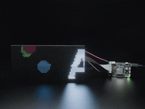
CircuitPython Powered Internet RGB Matrix Display
regal mirage
Ok, changing the USB-Mode in Arduino IDE to "Hardware CDC and JTAG" fixed my issue.
 dusky agate
does anyone know of a arduino library that play tones similar to the standard tone function but with volume control that works on the pygamer / pybadge etc? i had found the TimeFreeTone library which works fine but it blocks execution and the function can't be used in a timer from what i can tell, the same author has other libraries that seem to have volume control but looks like no samd support as far as i can tell so just kinda wondering if there is a library out there that does this or if someone has an example how to play tones with different volume levels on the pygamer ? I had also found Arcada.SetVolume function but all it does is save the value to a config file it does not actually have volume controls implemented as the comments with the functions source code also mention
runic quarry
Hmm, not sure if there's a better channel for this inquiry. I'm switching from Arduino IDE to ESP-IDF/VSCode for this project, but I'm using Arduino as a component, and continuing to use a number of Adafruit Libraries. Some of these (like Adafruit_BusIO) have CMakeLists.txt files that seem to exist for esp-idf. But they include a a project line (e.g. project(Adafruit_BusIO)) which ChatGPT insists will cause problems and shouldn't be there. It even quoted me a line from the Espressif build system docs saying as much, but the latest versions don't explicitly state that anymore. Since I try to verify everything chatgpt tells me to do, I'm hoping someone can chime in on this. It seems it really shouldn't be there, but I'm not 100% sure. I haven't yet tried to actually build.
stable forge
runic quarry
Hmm, not sure if there's a better channel for this inquiry. I'm switching from A...
I think this might be fine. various components( in esp-idf itself have project( entries, like components/json, components/lwip, etc. CMake is going to tell you whether it's wrong or not. Just go ahead and try the build.
 flint smelt
Hey, I'm trying to start a new CLUE project using PlatformIO (VSCode > Arduino IDE lol) but I'm getting an error after setting up the ini file with the board and Sensor Lab + Arcada with the following code:
#include <Arduino.h>
#include <Adafruit_TinyUSB.h>

#define LED_WHITE PIN_LED2

void ledToggle();

void setup() {
  pinMode(LED_RED, OUTPUT);
  pinMode(LED_WHITE, OUTPUT);

  Scheduler.startLoop(ledToggle);
}

void loop() {
  digitalWrite(LED_WHITE, HIGH);
  delay(50);
  digitalWrite(LED_WHITE, LOW);
  delay(5000);
}

void ledToggle() {
  digitalToggle(LED_RED);
  delay(1000);
}
Here's the ini file:
[env:adafruit_clue_nrf52840]
platform = nordicnrf52
board = adafruit_clue_nrf52840
framework = arduino
lib_deps =
    adafruit/Adafruit Arcada Library@^2.5.8
    adafruit/Adafruit Sensor Lab@^0.8.2
Sorry, I'm getting over a cold and my brain is a little foggy lol Here's the error: .../.platformio/packages/framework-arduinoadafruitnrf52/libraries/Wire/Wire_nRF52.cpp:32:10: fatal error: Adafruit_TinyUSB.h: No such file or directory
Copilot sent me in circles trying stuff that didn't seem to make a difference and I don't see any macro flags that need to be enabled
solemn cliff
note that if it's just to use vscode (I don't like Arduino IDE either) you can just use arduino-cli to compile and upload
(while using the IDE to install libraries and stuff)
flint smelt
True, I'm pretty sure that's all PlatformIO does under the hood, but I'm familiar with PIO so it's my go to lol
I might just try the cli and see what happens
flint smelt
Well now I'm confused. I got arduino-cli all setup, core installed, libraries installed (but not referenced yet) and a simple sketch compiling and "uploading" but the behavior of the LEDs is not changing with the new sketch. Both the board and arduino-cli act like an upload is happening but it continues to run the same blink pattern that I had on it previously
Also, those white LEDs on the front are no joke 😂
solemn cliff
yeah they are supposed to help with the color/gesture sensor inbetween
flint smelt
Wait, I'm dumb... I scrolled back through the commands I ran and realized I hadn't called compile since I compiled the original sketch that DID match the pattern that was previously on there. So I compiled and uploaded and it changed
flint smelt
So the sketch.yaml doesn't also install dependencies?!
 north galleon
hi hi, I am having a weird issue where my code will slow down and suddenly speed up (and also crash), IDK if there is a good way to monitor what is happening. Sadly I didn't get a rp2040 debug probe when they were in stock last.
north galleon
It actually may be a memory leak somewhere. First time working with c++ and I almost definitely have something in there gobbling ram that shouldn't be
flint smelt
This STEMMA MiniGPS is spitting out numbers that are off by a couple of decimal places but the library and it's examples don't give any indication of that being expected
Oh and one has the wrong sign
Like it should say something like 35.xxxx, -92.xxxx but instead says 3558.xxxx, 9252.xxxx
 lethal yarrow
north galleon
It actually may be a memory leak somewhere. First time working with c++ and I a...
lethal yarrow
north galleon
It actually may be a memory leak somewhere. First time working with c++ and I a...
Can you be more specific? Also, are you even using dynamic memory?
north galleon
It should be using dynamic memory (I am never calling new() at least). https://github.com/MacGuffin-Underscore/DelugeScreenPio repo is there, I think the culprit is on usbh (midi sysex message handling) or display (OLED data specifically)

GitHub
Deluge external screen through RP2040 USBA feather PIO - MacGuffin-Underscore/DelugeScreenPio
lethal yarrow
I'll have to look more closely later, but my gut instinct says it's probably related to your callbacks.
Also not sure why you're putting namespaces everywhere.
north galleon
I'm still new to Arduino/C++, I am kinda going by "stop the ide from yelling at me"
north galleon
overclocking it to 240Mhz seems to have corrected most of the crashing
lethal yarrow
north galleon
overclocking it to 240Mhz seems to have corrected most of the crashing
Ok that's odd because overclocking usually results in reduced stability. It's sounding more and more like your code was having trouble keeping up with the callbacks.
north galleon
I think that may have been it. I also had the buffer too low so the messages were coming through in parts that could crash it
north galleon
The code is still freezing up after about a minute of run time (less if I am doing things that re-draw the screen a lot). Is there some display buffer I am not clearing?
north galleon
aight, it's freezing even with no updates to display being sent. So it's something with a tick
north galleon
tracked it down to requestImage(). I think it may be stepping on toes and (based on luck) it is trying to draw twice in one tick from a double-recieve sysex message
gonna implement a bool to stop requesting if there is a message being processed and see if that fixes it
oop, nevermind, program just froze with my test case in removing request... back to figuring out why this is doing dumb stuff
 dry forge
Hi the dvi hstx library from ada fruit dosnt seem to be working on arduino currently on my set up atleast. I have triple checkedy wiring and the picoDvi libs are working but not the hstx one
my code compiles and uploads but when i debug it dosnt get past the display init
is any one else having this problem?
north galleon
good news! its not actually freezing... it's just going super fast like all my intervals all break and IDK why
const uint16_t interval_ms = 1000;
  static uint16_t start_ms = 0;
  if (millis() - start_ms < interval_ms) {
    return;
  }
  start_ms += interval_ms;
any reason that would break after a indetermenant amount of time?
I use it in quite a few different places at different speeds. but being static and const, and properly scoped to the function, should mean it isn't a issue, right?
I only noticed this because I wrote a little idle image on my oled that bobs up and down, and it moves very fast when it breaks (the led was doing the same, but it was so fast I assumed it was stalled HIGH or LOW)
sharp turret
north galleon
```
const uint16_t interval_ms = 1000;
static uint16_t start_ms = 0;
if (mil...
That code isn’t roll over safe. The incremented variable will roll over first and cause that if statement to be true UNTIL millis() rolls over.
The correct method is to compare the difference between the current time from a previous time to an interval, and then set the “previous” time to the “current” time.
north galleon
sharp turret
That code isn’t roll over safe. The incremented variable will roll over first an...
ah, that would make sense in why it seems random. since hitting millis() could change. Do you have any suggestions on how to implement it? I have this in like 15 different spots I need to fix :p
sharp turret
I suggest you implement it correctly
if ((currentMillis - previousMillis) >= interval) {
        previousMillis = currentMillis;
                // do the things
    }
Assuming both “millis” variables are unsigned long
north galleon
(^^)b
Ill get to work on changing it. Thanks!
yea, my numbers were also uint16, which makes sense that about every minute was when it would break down on average at 65000ms
north galleon
yea, that seems to have did it. Thanks! that was driving me crazy the last few days
 gloomy kelp
Hi all,
I'm stuck with an Adafruit Tiny USB related problem.
I have a QT Py RP2040 and a QT Py ESP32 S3 as part of a system in which the RP2040 is a USB Host and has the ESP32 connected to the RP2040 as a USB device. It all works ok with Serial going back and forth between the QT Py's
When I unplug the the ESP32 from the RP2040, the RP2040's arduino sketch correctly reports the tuh_cdc_umount_cb TinyUSB callback.
When I plug the ESP32 back into RP2040, nothing happens - the tuh_cdc_mount_cb doesn't report.
If I then reset the RP2040 (with the ESP32 connected), the system comes alive and Serial is working both ways across the RP2040 and ESP32, although tuh_cdc_mount_cb doesn't explicity get reported in the serial console.
I'm essentially looking for hot plugging, without needing to reset the USB Host! This should be possible right?
All the ESP32 is doing Serial.write for the most part.
Please help!
dusk orchid
gloomy kelp
Hi all,
I'm stuck with an Adafruit Tiny USB related problem.
I have a QT Py RP...
Should be possible yes. Worth trying the examples from the library, that deal with enumerating devices and mounting, as they support remounting too.
 thorny heart
I have a ESP32 Rev TFT Feather and a Stemma Soil Sensor and I'm trying to display the cap reading of the soil sensor on the screen of the Feather. My code works fine if I power over USB, but if I plug the soil sensor into the I2C port I'm unable to connect to the MAX17049 lipo charge monitor over I2C. Even if i remove all the soil sensor code from the program, just plugging it in prevents lipo.begin() from working for some reason. I've never used I2C before so maybe I'm missing something obvious
I'm wondering if the SS is reserving the I2C address the LiPo monitor wants to use
dusk orchid
The max1704x wants a battery connected or begin calls can fail
dusk orchid
Is it using a very long cable? Do the i2c addresses conflict (I don't think so but will look)?
dusk orchid
thorny heart
yeah i have the battery in and it works
Ah they use the same addresses. The max is constant https://github.com/adafruit/Wippersnapper_Components/blob/main/components/i2c/max17048/definition.json#L7 but soil supports 4addresses https://github.com/adafruit/Wippersnapper_Components/blob/main/components/i2c/stemma_soil/definition.json#L7
Usually there are some solderable pads to change address. Check the learn guide for soil sensor then make it use one of the alternative addresses. The code may need updating to specify the non-default address.
Specify the alternative address to the begin call like this:
https://github.com/adafruit/Adafruit_Wippersnapper_Arduino/blob/main/src/components/i2c/drivers/WipperSnapper_I2C_Driver_STEMMA_Soil_Sensor.h#L60
thorny heart
dusk orchid
Ah they use the same addresses. The max is constant <https://github.com/adafruit...
Thank you! this is exactly what i was looking for
 merry cargo
I'm attempting to use a Feather M0 Bluefruit LE to send mouse commands to a PC. The BleHidMouseButton seems a bit confusing. It has the actions "press", "hold", "click", "doubleclick" but no "release". I could do "AT+BleHidMouseButton=0" but that appears to release all pressed buttons.
What's the best way to, say, press the left button, press the right button, release the left button, release the right button?
Best I can come up with is to use "click" on a previously pressed button to release it, like:
AT+BleHidMouseButton=L,press
AT+BleHidMouseButton=R,press
AT+BleHidMouseButton=L,click
AT+BleHidMouseButton=R,click
Is there a better way?
solemn cliff
merry cargo
I'm attempting to use a Feather M0 Bluefruit LE to send mouse commands to a PC. ...
does your test work ? Releasing seems to be AT+BLEHIDMOUSEBUTTON=0
did you try this ?
AT+BleHidMouseButton=L
AT+BleHidMouseButton=LR
AT+BleHidMouseButton=R
AT+BleHidMouseButton=0
Here's what I got:
AT+BLEHIDMOUSEBUTTON=L - left button pressed
AT+BLEHIDMOUSEBUTTON=LR - left & right pressed
AT+BLEHIDMOUSEBUTTON=R - both released
AT+BLEHIDMOUSEBUTTON=0 - no change
Not sure why the 3rd command released the right button.
Thanks, though. Was worth a shot.
merry cargo
Aww, %#&@!!!! The arduino code's just fine. The testing app I was using was faulty. It took any mouse-up event as all-buttons-up.
So, it really is just a matter of, on any change of button state, listing the pressed buttons and sending "0" if none are pressed.
These all did exactly what they were supposed to do when I wrote my own mouse event monitor.
AT+BLEHIDMOUSEBUTTON=L - left down
AT+BLEHIDMOUSEBUTTON=LM - left,middle down
AT+BLEHIDMOUSEBUTTON=LRM - left,right,middle down
AT+BLEHIDMOUSEBUTTON=RM - right,middle down (i.e. left up)
AT+BLEHIDMOUSEBUTTON=R - right down (i.e. middle up)
AT+BLEHIDMOUSEBUTTON=0 - right up
Lesson learned: Make sure the mouse testing app actually tests mice. 😡
And, yeah, I know people rarely press more than one mouse button at a time. But 40 years of writing software has taught me that "rarely ever happens" will occur immediately after handing off an app to end users. 😄
 brave dragon
I can't get my mouse to work with rp2040 with usb host even tho its reading all the bytes correctly in serial monitor
When I used all 3 files from https://learn.adafruit.com/using-a-mouse-with-usb-host/arduino, it shows left, right and middle clicks, for movement it shows X:0 Y:0, same for scrolling up/down and side buttons. If I use a different code made with ai, it shows the bytes for every action (2nd picture), but still, I can't get the mouse to work while plugged into rp2040, it can only read bytes from it but won't copy my clicks/actions.
I have tinyusb, pico pio libs installed ofc.
Can anyone help?


In a few words - I want it to copy my mouse movements, not just read the bytes.
livid osprey
brave dragon
I can't get my mouse to work with rp2040 with usb host even tho its reading all ...
The rp2040 usb host will not act as a pass through unless you program it to do so. The tutorials show how to use a mouse with an rp2040, but in order to use that as a mouse as well, you need to configure the rp2040 as a usb mouse to send the mouse actions from the rp2040 to the pc. https://www.instructables.com/Raspberry-Pi-Pico-As-HID-Mouse/ can be a good basis for this, but you’ll have to make the modifications to add your usb mouse input and send the corresponding data.

Instructables
Raspberry Pi Pico As HID Mouse: Hello Everyone.
So here's a fun little project that tackles a major issue with the Raspberry Pi Pico Microcontroller.
The Raspberry Pi Pico's pinout information is located on the bottom side of the board, which makes prototyping difficult. When we m…
brave dragon
livid osprey
The rp2040 usb host will not act as a pass through unless you program it to do s...
I found a code on github that works almost perfect, all buttons register but when I move the mouse, coursor doesnt move. Its possible to fix that with proper descriptors in the code right?
 sinful dragon
Cross-posting here incase any has some ideas. Much appreciated 🙏🏽
 limpid temple
I'm looking into programming a Raspberry Pi Pico with Arduino code. Assuming I get that to work (I've found some guides online), does anyone know if the Adafruit MCP3008 library will work on the RP hardware? https://github.com/adafruit/Adafruit_MCP3008/tree/master
I'd like to add an external ADC, and 8 channels at 10 bits is plenty.
inland gorge
limpid temple
I'm looking into programming a Raspberry Pi Pico with Arduino code. Assuming I g...
Yes the MCP3008 will work with the Pico. If your goal is a way to add more poteniometers to a project, you don't necessarily need more ADCs, you can instead use an analog mux like the 4051. Here's one Arduino tutorial: https://forum.electro-smith.com/t/cd4051-multiplexer-tutorial-is-here/3481 (it's for the Daisy board, but it's still just Arduino)
With a mux you can feed 8 pots into one ADC. It's pretty great. I use it in many projects, e.g. https://github.com/todbot/eight_by
limpid temple
inland gorge
Yes the MCP3008 will work with the Pico. If your goal is a way to add more pot...
I'm actually looking to adapt a project that uses 8 multiplexers, going into 8 analog pins on a different dev board (Itsy Bitsy) -- it's a project with LOTS of potentiometers (or the potential to expand to lots).
Alternatively, I wouldn't be opposed to having one Pico for every three multiplexers, since the Picos are inexpensive, but I've read that the ADCs on the Pico aren't the most stable.
Also - thanks for the reply! Sounds promising enough that I should pick up a Pico and start breadboarding.
inland gorge
limpid temple
I'm actually looking to adapt a project that uses 8 multiplexers, going into 8 a...
That sounds really cool! And yes, the RP2040 ADCs not so great but good enough for knobs usually. In theory they are 12-bit, but in practice (like most MCU ADCs) only around 8-bit usable. There's averaging tricks to gain a bit or so back.
On the Pico specifically you can also turn its noisy-but-efficient voltage regulator into a quieter mode (GPIO23 to HIGH) to reduce the noise a bit
limpid temple
Good go know!
My project is a MIDI controller, so I really only need 7 bits of resolution - but the 10 bits on the Itsy Bitsy worked well for detecting changes.
My code oversamples (reads each pin N times and then takes the average), but I was still getting a lot of jitter (mostly on pin A0, regardless of which multiplexer I attached to it). Then I changed it to only update if the analogRead was greater than 4 in either direction from the last read (on a 10-bit scale), and scale to 0-127 to send the result, and it was solid.
 floral locust
Hello, I am experiencing a persistent 'Initializing SD card...initialization failed' error when using the built-in microSD card slot on my Adafruit Grand Central Metro M4. I am running the standard 'CardInfo' example sketch. I have confirmed that the board is correctly selected as 'Adafruit Grand Central M4 (SAMD51)' in the Arduino IDE and that code uploads successfully. I've also verified that the SD card is formatted as FAT32, is firmly seated, and that pin 10 is correctly specified as the SDCARD_CS_PIN. Furthermore, I have tested with multiple different microSD cards, all formatted to FAT32, and the issue persists. I have also disconnected all other peripherals (microphones) to isolate the problem, but the SD card still fails to initialize. Based on these troubleshooting steps, it appears there might be a hardware defect with the built-in SD card slot on the board. Could you please assist
above is the code that doesnt work
inland gorge
floral locust
above is the code that doesnt work
How do you have the SPI bus wired to the SD card? I would try this example code from the Grand Central Learn Guide, making sure to wire it up like the guide has it: https://learn.adafruit.com/adafruit-grand-central/arduino-sd-card-example

This dev board is so big, it's not named after a Metro train, it's a whole freakin' station!
floral locust
It gave the same error " Initializing SD card...initialization failed!"
inland gorge
floral locust
It gave the same error " Initializing SD card...initialization failed!"
Do you have the SPI pins wired to the SD card?
Oh apologies. It has a built in card reader?
floral locust
yes
inland gorge
floral locust
yes
I found my Grand Central M4 and a microSD card and unfortunately got it to work. I'm using a 4GB SanDisk card formatted FAT32. First I tried the CardInfo sketch in the SD card examples (https://github.com/arduino-libraries/SD/blob/master/examples/CardInfo/CardInfo.ino) and made no changes to the sketch except const int chipSelect = SDCARD_SS_PIN; It worked.
I also tried the above linked test, with the single change of const int chipSelect = SDCARD_SS_PIN; and that also worked.
Perhaps because I'm using the official Arduino SD card library instead of the Adafruit fork?
Edit: maybe not, I just tried SdInfo (https://github.com/adafruit/SdFat/blob/master/examples/SdInfo/SdInfo.ino) and that worked too
 prisma valve
curious, why is the yOffset of ' ' set to 1?
https://github.com/adafruit/Adafruit-GFX-Library/blob/master/Fonts/FreeSans12pt7b.h

GitHub
Adafruit GFX graphics core Arduino library, this is the 'core' class that all our other graphics libraries derive from - adafruit/Adafruit-GFX-Library
prisma valve
just trying to understand the non-monospace fonts in general
 upper pebble
hey party people, I'm trying to use an Arduino with a PCA9685. I'm using the Adafruit PWM servo library examples. when I upload the code and supply power to the arduino and external power to the PCA9685, I don't see any servo movement. The servos seem to be powered as I can't move the horns, but I'm not seeing a power light on the PCA9685. I believe this confirms if the board is receiving power from the arduino - I metered the connections and found that 4.9V are going into the PCA9685. I also did a connectivity check on the hookup wires I'm using and they seem to be making a connection. Any idea what's going on?
leaden walrus
upper pebble
hey party people, I'm trying to use an Arduino with a PCA9685. I'm using the Ada...
can you share the code for the sketch you are running? a photo of your setup showing how everything is connected would also help.
upper pebble
leaden walrus
can you share the code for the sketch you are running? a photo of your setup sho...
I followed this guide here which includes the wiring diagram:
https://www.instructables.com/Mastering-Servo-Control-With-PCA9685-and-Arduino/
The code I used is here: https://github.com/Circuit-Digest/PCA9685-multiple-servo-control-using-Arduino/tree/main
Do you think a code issue could be causing a lack of power?

Instructables
Mastering Servo Control With PCA9685 and Arduino: Our step-by-step guide on using the PCA9685 16-channel PWM/Servo Driver with Arduino! In this tutorial, we focus on how to control multiple servo motors efficiently. Let's dive in!
GitHub
Struggling to control multiple servos with your Arduino? Don't worry, this quick tutorial has you covered! Learn how to use the PCA9685 module to effortlessly control 8 servos simultaneous...
leaden walrus
try an i2c scan just to sanity check the basic connection with the pca
just verify an address shows up, and it's the one being used by the sketch (0x40)
there are also examples in the library itself:
https://github.com/adafruit/Adafruit-PWM-Servo-Driver-Library/tree/master/examples
upper pebble
I just ran that scanner file (super useful) but it's saying no i2c found. I think this goes back to the PCA board not powering on?
leaden walrus
that's where photo of setup showing connections would help
upper pebble
let me get a clear photo but I double checked and I'm using the connections in the instructables example. one moment...

I do read 5v at the inpt power pins on the PCA so I think it's getting power
Now that I think about it... should the SCL / SDA wires be connected to PWM in or out? Also this arduino is extremely old
floral locust
I need help with my code I. am trying to collect data from a microphone into an SD card, and I have written this code.
C:\Users\hikme\AppData\Local\Temp.arduinoIDE-unsaved2025517-24456-1c90mkz.n5u\sketch_jun17b\sketch_jun17b.ino: In function 'void configureADC_DMA_Timer()':
C:\Users\hikme\AppData\Local\Temp.arduinoIDE-unsaved2025517-24456-1c90mkz.n5u\sketch_jun17b\sketch_jun17b.ino:120:17: error: 'DMAC_GCLK_ID' was not declared in this scope; did you mean 'DAC_GCLK_ID'?
120 | GCLK->PCHCTRL[DMAC_GCLK_ID].reg = GCLK_PCHCTRL_GEN_GCLK0 | GCLK_PCHCTRL_CHEN; // Use GCLK0 for DMAC
| ^~~~~~~~~~~~
| DAC_GCLK_ID
C:\Users\hikme\AppData\Local\Temp.arduinoIDE-unsaved2025517-24456-1c90mkz.n5u\sketch_jun17b\sketch_jun17b.ino:125:25: error: 'MCLK_APBCMASK_TCC0' was not declared in this scope; did you mean 'MCLK_APBCMASK_TCC2'?
125 | MCLK->APBCMASK.reg |= MCLK_APBCMASK_TCC0; // Corrected MCLK APBCMASK access for TCC0
| ^~~~~~~~~~~~~~~~~~
| MCLK_APBCMASK_TCC2
exit status 1
Compilation error: 'DMAC_GCLK_ID' was not declared in this scope; did you mean 'DAC_GCLK_ID'?
thats the code and erorr i dont understand the problema and need help fixing it.
leaden walrus
move pins. youre on digital 4/5, not analog 4/5 (A4 and A5)
 upper pebble
leaden walrus
move pins. youre on digital 4/5, not analog 4/5 (`A4` and `A5`)
upper pebble
leaden walrus
move pins. youre on digital 4/5, not analog 4/5 (`A4` and `A5`)
womp, I'm an idiot. let's try again...
 upper pebble
what a rookie mistake. I've got to jump but I'll try again tonight, thanks for all the help!!
leaden walrus
continue with trying to get the i2c scan to work and report address
the battery power can be disconnected for that
 eager marsh
Heya, I'm trying to create a custom BLE GATT characteristic using the Bluefruit library on my nRF52833. Unfortunately when I try write to it via the BLE connection, Bluez tells me the operation "isn't authorized".
I have set the service the characteristic belongs to as open cpp superiot_service.setPermission(SECMODE_OPEN, SECMODE_OPEN); and the same for the characteristic itself:
    superiot_characteristic.setProperties(CHR_PROPS_WRITE | CHR_PROPS_WRITE_WO_RESP | CHR_PROPS_READ);

    superiot_characteristic.setProperties(CHR_PROPS_WRITE | CHR_PROPS_WRITE_WO_RESP | CHR_PROPS_READ);
```.

Weirdly, if I ask my laptop to list the properties of the device, it always says the properties are `write-without-response` and `read`, no matter what I actually set them to. If I set them to `write` only, then it still says `read` is enabled, but the read command does fail appropriately.

Any help would be much appreciated \:)When are you setting the properties? It should be before any connection is made.
Another possibility is that the host OS is caching discovery info. Try forgetting the device completely and then reconnecting?
eager marsh
stable forge
When are you setting the properties? It should be before any connection is made....
Here is the setup:
Bluefruit.begin(1, 1);
    Bluefruit.setTxPower(4); // Set transmit power to 0 dBm //********************************************************************************************************************************

    Bluefruit.Periph.setConnectCallback(peripheral_connect_callback);
    Bluefruit.Periph.setDisconnectCallback(peripheral_disconnect_callback);

    peripheral_bleuart.begin();
    peripheral_bleuart.setRxCallback(peripheral_bleuart_rx_callback);

    superiot_service.setPermission(SECMODE_OPEN, SECMODE_OPEN);

    superiot_service.begin();

    // Enable read/write
    superiot_characteristic.setProperties(CHR_PROPS_WRITE | CHR_PROPS_WRITE_WO_RESP | CHR_PROPS_READ);
    // Give all devices permission to read/write
    superiot_characteristic.setPermission(SECMODE_OPEN, SECMODE_OPEN);
    superiot_characteristic.setFixedLen(3);
    superiot_characteristic.setWriteCallback(characteristic_write_callback);
    superiot_characteristic.begin();
Forgetting the device and re-connecting did indeed fix the properties showing up incorrectly so thanks for the tip :), but the issue with writing is still present.
It seems to work when writing from my phone instead, so I guess there must be something wrong with my laptop 🥴
stable forge
You can use the nRFConnect app to list the characteristic properties. It shows more info on Android than iOS. Also use it in landscape mode.
eager marsh
Yeah that's what I used successfully :)
Still need to figure out why it's not working on my laptop, but can safely say that's nothing to do with Adafruit ;)
Thank you for the help!
stable forge
I don't know if it will help, but you could try a known-working example like https://learn.adafruit.com/bluefruit-nrf52-feather-learning-guide/custom-hrm and change the properties (after forgetting) to see if it makes any difference.
Also, on the laptop, try also turning BLE off completely and then turning it back on.
blissful summit
Wondering how I would start to program this to just happen in protomatter as a demo, instead of just creating gifs for the gifplayer

I know it would have something to do with creating an array of pixels with every frame and then animating them down And fading out the old ones each frame
But I've only really learned how to use an update function and I'm not sure how the timing works. Back to the books I guess
I know time is a module
I also found this cool clock repo but it's older back when it used the secrets.py file, It was made for the M4 but pretty sure the code would run on the S3

Download the: Demo for 64x32 RGB Matrix display with Adafruit Matrix Portal M4. My great friend Hari made the Animated Clock and also created the menu so I can run other demos, like Pixel Dust! Created using Arduino IDE by Hari Wiguna (Lookup his channel here on YouTube!!! https://www.youtube.com/@HariWiguna ) I'll ask Hari if we can upload thi...
Very cool animation on the digits imo, id like to get it running in green or amber
blissful summit
Only thing is it's C++ and I know we're trying to push circuit python here
solemn cliff
what do you mean ? This is the Arduino channel, aren't you looking for Arduino code ?
livid osprey
blissful summit
Only thing is it's C++ and I know we're trying to push circuit python here
As far as I know, Adafruit pushes circuitpython as a means of improving accessibility to the hobby, not as a total replacement for other languages. There’s nothing wrong with sharing projects in any language, especially in the relevant channels.
blissful summit
livid osprey
As far as I know, Adafruit pushes circuitpython as a means of improving accessib...
Ok just making sure i'm not muddying the water so to speak. Im a noob at this world
I read that c++ will execute much faster which is why i prefer it
Working with tiny chips i want as much efficiency as i can get
leaden walrus
totally no issues discussing c++ here, i.e. on this adafruit discord. there are the various channels we try to direct people to. this one is arduino so best for c++. there's a circuitpython one, but also a raspberry pi one, and various others, etc.
execution speed is a whole topic of discussion. compiled vs interpreted. but, yes, in general c++ code (compiled) will run faster. circuitpython itself is written in c:
https://github.com/adafruit/circuitpython
inland gorge
And Arduino is all C++
blissful summit
inland gorge
And Arduino is all C++
Thank you sir, that was one of the things I wondered. If it does any other code
Ok now it makes more sense. I didn't realize even piomatter is mostly C as well
inland gorge
blissful summit
Thank you sir, that was one of the things I wondered. If it does any other code
Inside of any Arduino sketch, you can use C++, C, assembly. You can also call any lower-level SDK functions (like for instance, ESP-IDF functions for WiFi that don't have exact Arduino counterparts). The Arduino "API" is really a set of mostly-agreed-upon common functions like "setup()", "loop()", "pinMode()", "digitalWrite()", etc. It's not very strict, so some Arduino cores do some more advanced things slightly differently. For example, being able to set which pins to use for an I2C bus is different across cores: on Pico RP2040, you use Wire.setSDA() & Wire.setSCL() but on ESP32 you use Wire.setPins(sdaPin,sclPin)
blissful summit
inland gorge
Inside of any Arduino sketch, you can use C++, C, assembly. You can also call a...
I think I saw the something with pins in the protomatter examples, I was wondering where those values were coming from
All of this is really helpful
Just googled my own info here and I totally forgot that python is basically an interpreter
inland gorge
blissful summit
Just googled my own info here and I totally forgot that python is basically an i...
Yep, but in CircuitPython the core libraries are written in C so you can still do some fast things. But any time you start doing big computation in Python, you'll take a speed hit. So then you may want to move to Arduno or a board-specific SDK (but Arduino is really just a wrapper around board-specific SDKs, so I stay in Arduino in those situations to get the benefit of an easier API while also getting the speed boost). So usually I start in CircuitPython, see how far I can go and only if I need to, switch to Arduino
blissful summit
Thanks for the help though. I was wondering how things are being included without being in the source root directory and it's just because some libraries are part of the Arduino IDE
blissful summit
I keep getting issues with these 😅 I have a library installed but when I compile it says it's not
Actually a header file but it is there
leaden walrus
there's a lot of auto-magic that goes on with arduino
how did you install the library? what library is it?
leaden walrus
it should work to place that in the libraries folder - in a subfolder
typical layout is a subfolder per library
if its not a library, but something that's part of the sketch, it's possible to have multiple files for the sketch
blissful summit
leaden walrus
if its not a library, but something that's part of the sketch, it's possible to ...
I installed the required libraries using the Arduino IDE but for some reason I'm looking at the file in the directory it looks for and it's not recognizing it. There is a "7:10" on the end of it
leaden walrus
not sure how that happened. may be an issue with that library? or with the installer?
does the library have a name?
or do you know its repo location?
blissful summit
leaden walrus
does the library have a name?

GitHub
An Adafruit GFX Compatible Library for the ESP32, ESP32-S2, ESP32-S3 to drive HUB75 LED matrix panels using DMA for high refresh rates. Supports panel chaining. - mrcodetastic/ESP32-HUB75-MatrixPan...
leaden walrus
should show up as ESP32 HUB75 LED MATRIX PANEL DMA Display in the Arduino Library Manager
and current version is 3.0.12
or maybe .11 actually

it installed ok here
blissful summit
I think I found the error
leaden walrus
$> ls
ESP32-HUB75-MatrixPanel-I2S-DMA.cpp     ESP32-VirtualMatrixPanel-I2S-DMA.h
ESP32-HUB75-MatrixPanel-I2S-DMA.h       platforms
ESP32-HUB75-MatrixPanel-leddrivers.cpp
The define line doesn't match the console output

Not sure if that means anything
leaden walrus
what sketch are you compiling?
what's this sketch code?

alternatively, try compiling one of the examples in the library
i'm not seeing any issues compiling the 1_SimpleTestShapes example for an ESP32 Dev Module
blissful summit
Weird. I can't get that one to verify
I'll try my laptop maybe it's a problem with my pc
leaden walrus
what's the full text of the error message? all of the red text
it's cut off in the photo above
blissful summit
Sorry I need to install discord lol
I get the same error in Ubuntu

Camera lens is smashed sorry
Oh man now I see what's its telling me
Line 7 from that header has an error
blissful summit
esp_err.h, I can't seem to find which library that's from
leaden walrus
set the board to be your actual ESP32 board

it's set to something M4 based, which is a different Arduino Board Support Package, and does not have that missing header file.
blissful summit
Ok makes sense
blissful summit
leaden walrus
it's set to something M4 based, which is a different Arduino Board Support Packa...
That's actually super helpful information because it's still a matrix portal but it's the older one
blissful summit
leaden walrus
it's set to something M4 based, which is a different Arduino Board Support Packa...
So it's a board file not a library thing. Makes sense. I googled around and found it in the esp32 Arduino library on git. I had to take a break and go get food but I'll try the S3 when I go back in
Makes even more sense because I read somewhere that the M4 isn't actually running the board with the esp32. It's only for Wi-Fi functionality
It uses a second ship to drive the panel
Chip* cortex
My room's going to look like cyberpunk in a minute
I have another clock project that is actually made for the M4. I'm going to do next. It has animated digits when it changes seconds
solemn cliff
the Matrix Portal M4 is running a SAMD51 main processor (an arm core M4, hence the name), and has an ESP32 on the board as wifi coprocessor (running the Arduino Nina firmware). The Matrix Portal S3 has an ESP32-S3 as main processor and doesn't need a coprocessor for wifi.
blissful summit
solemn cliff
the Matrix Portal M4 is running a SAMD51 main processor (an arm core M4, hence t...
Are esp32s arm-based?
 blissful summit

Also got this repo working. Its an open ntp server
The clock is an hour behind though
Eastern US (gmt -5:00)
It didnt have a URL in the code, jusglt said open NTP
I was asking about buttons, they helped in the circuitpython channel
Just change it with a button but kinda defeats the purpose of being accurate lol
blissful summit
leaden walrus
it's set to something M4 based, which is a different Arduino Board Support Packa...
Ty again for this. Just changed to the S3 and it started compiling. Getting warnings but no failure
dusk orchid
blissful summit
Ty again for this. Just changed to the S3 and it started compiling. Getting wa...
Did you get that sweet digit transition animation going? I'm looking forward to nicking that one 🙂
blissful summit
dusk orchid
Did you get that sweet digit transition animation going? I'm looking forward to ...
Working on it now. It requires the secrets.h tab and trying to figure out how to declare it there
dusk orchid
secrets.py? nice one either way
blissful summit
dusk orchid
secrets.py? nice one either way
That's circuit python
This is stored in the sketch so I think it encrypts that tab or something
Theres no writeup in the git, just winging it lol
dusk orchid
ooo, spicy
blissful summit
Guess I could just plug it in at midnight like a broken old school digital clock 
But I wanna figure this out lol
blissful summit
dusk orchid
ooo, spicy
I can get it to compile and run but I'm having trouble getting the SSID to connect
upper pebble
It all worked! Thanks @leaden walrus
blissful summit
created arduino_secrets.h tab and did #define SECRET_SSID and SECRET_PASS
same variables from the project code
blissful summit
I think I found what's wrong. It wasn't coded using a secrets.py file. It was just put directly into the code
Sorry I meant to say arduino_screts.h
blissful summit
dusk orchid
ooo, spicy
Yes. Just have to create arduino_secrets.h and add the chunk of code with "credentials". Then where that code was, add #include "arduino_secrets.h"
Still an hour slow 🤔
blissful summit
Fyi the colors ain't easy to figure out on this repo. But I stared at code for hours and figured it out
brave dragon
does anyone know how to make rp2040 receive hid reports from another program?
stable forge
brave dragon
does anyone know how to make rp2040 receive hid reports from another program?
in arduino, if you want it to be a usb host, see some examples here: https://github.com/adafruit/Adafruit_TinyUSB_Arduino/tree/master/examples. There are some open issues on this. It's also possible in CircuitPython.
also see https://learn.adafruit.com/adafruit-feather-rp2040-with-usb-type-a-host/usb-host-device-info -- maybe read this first
brave dragon
yeah I've already made my rp2040 copy the exact moves I do with my mouse but I also want it to receive hid reports from another program and I can't get it to work
solemn cliff
what do you mean another program ?
brave dragon
a program to send input made in pyton or c++ like for example see a purple color on the screen = send signal to rp2040 by hid report to click left mouse button
ik screen reading is another thing but I cant get it to send hid reports to rp2040
solemn cliff
and what have you done so far ?
brave dragon
well I have my rp spoofed as a mouse, my mouse plugged into the host and its copying the mouse moves but cant receive hid reports from a program, I tried to make a test program using claude ai just to test sending hid reports for 2 hours but still couldn't get it to work
it has 6 hid interfaces and 1 of them is supposed to be the interface for raw hid inputs
stable forge
brave dragon
a program to send input made in pyton or c++ like for example see a purple color...
Are you saying you want a program running on the host to look at the screen, and then send a message to the RP2040 to then have it click a mouse button? So the only purpose of the RP2040 is to do the clicking? If you could do the clicking via a program running on the host, that would be fine?
brave dragon
stable forge
Are you saying you want a program running on the host to look at the screen, and...
basically yes just for the clicks + movement, I wanna make a program that would make the rp2040 click the mouse on specific targets or move the mouse onto them, but without using com port so hid reports instead. Double input is detected in the game, so I don't have mouse and rp2040 connected seperately in the pc, mouse is plugged into rp2040, its copying the mouse moves well, but I want it to receive hid reports from the program too
stable forge
brave dragon
basically yes just for the clicks + movement, I wanna make a program that would ...
what os is running on the host?
brave dragon
stable forge
what os is running on the host?
windows
if thats the type of os we're talking about
stable forge
brave dragon
windows
There are ways to simulate HID input directly on Windws. Not so easy to find examples, but here's one: https://github.com/michaelnoonan/inputsimulator
brave dragon
yes but I want the input to come from the rp2040 to the mouse, not from the software itself, because its gonna be blocked so not gonna work
brave dragon
the input is not gonna be sent with the game open because of anticheat program
stable forge
so you want to make a cheater?
brave dragon
yes
stable forge
you don't have to send stuff to the RP2040 via HID reports. You could send info via a COM port to USB serial
brave dragon
the thing is that sending input via serial is now detected by anticheat, and the new method uses raw HID reports. That’s why I don’t want to use a COM port. basically, I need it to be: software (detects a target) -> sends HID report (to click mouse or move cursor) -> RP2040 -> RP2040 sends HID input to PC (spoofed as legit mouse)
stable forge
It's probably possible using the libraries I showed you above. At this point I'm not planning to help further, given the goal.
brave dragon
understandable
blissful summit
blissful summit
Still an hour slow 🤔
Fixed em. It doesnt actually ask for timezone in the code
Just sets UTC-? Manually
 formal mulch
hi has anyone gotten serial output from a attiny before?
im specifically using a attiny1616 breakout board with a updi friend for programming and a cp2102 friend for serial output and trying to use uart
 oblique nova
I think I've done that with a attiny 412, but I'll need to check my older projects. (I also just used avrgcc ) Not an expert 🙂 but is there a code or other info you can share? If not me, someone more knowledgeable might spot any issue
oblique nova
oblique nova
I think I've done that with a attiny 412, but I'll need to check my older projec...
I have this from one of the projects - https://pastecode.io/s/bzrjgyg7 ( iirc, I just used Atmel start to generate some code, and then grabbed the initialization of the registers and so forth from there.)
leaden walrus
@formal mulch i have. using this bsp:
https://github.com/SpenceKonde/megaTinyCore
are you using that also?
arduino Serial output ends up being on PB2:
https://github.com/SpenceKonde/megaTinyCore/blob/master/megaavr/extras/ATtiny_x16.md
formal mulch
oblique nova
I think I've done that with a attiny 412, but I'll need to check my older projec...
I'll send some later but I'm sure its completely wrong lol I was trying to use hardware serial
formal mulch
leaden walrus
<@280522487882579968> i have. using this bsp:
<https://github.com/SpenceKonde/me...
yes im using megatinycore and Im very sure im uploading correctly ive gotten an led blinking
brave dragon
I'm using a code to copy my mouse movements, working as a passtrough, but the mouse every few mins slows the sensitivity down by like a half, and on hz mouse test it goes down from 1000hz to 500hz and I need it fully working on 1000hz
formal mulch
leaden walrus
arduino `Serial` output ends up being on `PB2`:
<https://github.com/SpenceKonde/...
oh hm i think i had the cp2102 friend connected to pb2 and I wasnt really seeing anything. thank you for verifying thats correct though
formal mulch
leaden walrus
more info:
<https://github.com/SpenceKonde/megaTinyCore/blob/master/megaavr/extr...
this documentation is really good, I hadnt read it before thank you
leaden walrus
just hooked one up to verify. this basic example works:
int count = 0;

void setup() {
  Serial.begin(115200);
}

void loop() {
  Serial.println(count++);
  delay(1000);
}
seeing this on the serial output via a USB-serial cable:
0
1
2
3
4
 quartz furnace
Hello I have the follwoiing code I need help with, it is a LORA module that receives a message and I want to ask if what is received is what is expected.
void rxCBFunc(uint8_t from, void *buffer, uint16_t size, int8_t rssi, int8_t snr){
char *p = (char *)buffer;
Serial.print("recv from: ");
Serial.println(from, HEX);
Serial.print("recv data: ");
for(uint8_t i = 0; i < size; i++){
Serial.print(p[i]);
}
Serial.println();
Serial.print("rssi=");Serial.println(rssi);
Serial.print("snr=");Serial.println(snr);
}
it has the result in buffer, and then the next line appears to put the contents in charp
would I need a strcmp ?
quartz furnace
I think I figured it out, they have another example that has "memcpy(p,buffer,size); // Memory copy, copy the data from buffer to the p array"
oblique nova
quartz furnace
I think I figured it out, they have another example that has "memcpy(p,buffer,s...
It probably won't hurt, but it also doesn't seem to be doing anything useful. (p and buffer will point to the same location.) That initialization doesn't really do anything more than type a void * pointer into a char * pointer. Fwiw, the original code seems fine as-is; assuming the data being sent is an array of char)
formal mulch
leaden walrus
just hooked one up to verify. this basic example works:
```cpp
int count = 0;
v...
oh really you dont need to set any of the pins? thats what i was getting from the Ref_Serial.md but maybe I was misunderstanding
leaden walrus
formal mulch
oh really you dont need to set any of the pins? thats what i was getting from th...
shouldnt need to if using the bsp default - from the pinout in the repo = pb7
formal mulch
leaden walrus
shouldnt need to if using the bsp default - from the pinout in the repo = pb7
pin 7 but pb2 right?
 formal mulch
sick im getting data now tysm!
 midnight sleet
is there a way to attach a debugger to a circuit playground bluefruit?
I'm having a really weird issue which is slowly driving me insane
also, um, what the heck is going on here?

is there a max stack size?
prisma valve
anyone know how to fix this? even tried manually reuploading the binary firmware and uf2 file and no shot

what i suspect is happening is there's probably some VSCode extension or background Thonny process hogging the serial port
blissful summit
A basic clock was ported over to the matrix portal m4 but i want to port the remix app. It has weather and date


Looks like its a matter of including the correct library and re-coding the logic to work with adafruit library
So basically wrtiting the whole sketch over
blissful summit
I just noticed the part where it says see simpletest for introductory sketch
stable forge
prisma valve
anyone know how to fix this? even tried manually reuploading the binary firmware...
which board is this? which serial port in the Port menu, and how was it labeled. (It's very had to read this - tiny and low contrast. Copy/pasting the errors as text would make it more readable.)
yes, if you have the port open for serial printing in another terminal application, you'll see that problem.
 shy ridge
I think I may be missing something whether it is hardware or software related. My original plan was to use a Nano RP2040 Connect, the Adafruit MicroSD card breakout board, and the adafruit RA8875 driver with a tft screen to display a 5x3 button matrix of images that I can press but I have found no way of quickly loading those images onto the screen. Through SD card it is slow which makes sense, but the .raw files (31KB x 15) are too large for the ram on the RP2040.
Is there something in the software department I could do to load these much quicker or if not, should I add a module, replace the rp2040 with a different board that is similar in pincount and size, or go wild and build a board with kicad that uses a more powerful ic and removes some of the unneeded features?
stable forge
shy ridge
I think I may be missing something whether it is hardware or software related. M...
do you need the "Connect" aspects of the board? Do you need all the raw image files loaded at once? What is are the pixel dimensions of each image? What graphics library are you using?
the usual thing to do is to make a single image that is a composite of all the sub-images
what are these images? Are they photos or just text on colors? What are the dimensions of the TFT?
Are you using one of our guides as a tutorial?
shy ridge
stable forge
do you need the "Connect" aspects of the board? Do you need all the raw image fi...
The original files were 24bit .bmp files but I used .raw as they are generally faster for loading. I would like them to be loaded at once so making a composite would work, I would juse be concerned of the file size of it in the composite if I was to store that in ram. The pixel dimensions for each image is 160x160px and the tft screen is 800x480. The images ideally will be images squashed down to 24bit bmp files but for testing I made solid background files with text a-z on them to differentiate them. I have been using the adafruit guides to try and piece together the code as I wasn't able to find a single guide that would do what I needed with the hardware I had. I used the guide for the ra8875 to get the example code working, and then the sd card guide for reading files on the sd card. I also looked into using the PicoDVI guide you have to try and do some hardware acceleration on the board but that wouldn't work with the RA8875
And in terms of the connect aspects of the board some of them would be cool but they are not needed at all since for now the plan is for this to be a USBHID device
stable forge
do you need to change the images, or just load the whole screen once?
shy ridge
I would need to change the page on the screen so I would need to change the composite "image" but not the individual "images"
stable forge
so you tap one image, and then it goes to a submenu of new choices? something like that?
shy ridge
Exactly
stable forge
how many different full-display pages are there? one top level 3x5 and then 15 submenus?
shy ridge
I would say that would be the max case, It will probably be less (around 10) and then the top level 3x5
stable forge
are these photos or simpler graphics? Do you need 24-bit color?
shy ridge
ideally they would be photos and 24-bit color depth
stable forge
looking at some things...
an Espressif board or RP2350 board with PSRAM I think would do it for you. PSRAM usually starts at 2MB
I looked at this project: https://learn.adafruit.com/touch-deck-diy-tft-customized-control-pad/assemble-the-touch-deck, which is an RP2040, but a smaller display (480x320). This video shows it refreshes relatively slowly: https://www.youtube.com/watch?v=TKZ7MEogUmU. That is CircuitPython, which uses slower graphics, and it's also reading from SD

Choo! Choo! This is the RP2350 Metro Line, making all station stops at "Dual Cortex M33 mountain", "528K RAM round-about" and "16 Megabytes of Flash town" and a ...
many Espressif boards with PSRAM: https://www.adafruit.com/search?q=psram+esp32
Adafruit Industries, Unique & fun DIY electronics and kits : Search Results - Tools Gift Certificates Arduino Cables Sensors LEDs Books Breakout Boards Power EL Wire/Tape/Panel Components & Parts LCDs & Displays Wearables Prototyping Raspberry Pi Wireless Young Engineers 3D printing NeoPixels Kits & Projects Robotics & CNC Accessories Cospla...
shy ridge
Hmmm okay. Is there a preference as to which board out of the two? I am looking to put this onto a pcb at some point to keep everything together. Also is there a perference between arduino ide, circuit python, or another ide that would be better suited for this?
stable forge
is this a one-off, or you're making multiple?
have you designed and populated boards before?
and 800x480 is a requirement?
shy ridge
For protyping a one off, but in the end having an open source project where people can make and customize their own
stable forge
what is the diagonal measurement of the screen?
programming language is your choice -- what you're comfortable with
shy ridge
I have designed and populated boards before (even with 0201 packages). The TFT I am using is this one https://www.adafruit.com/product/1680 which is 5" diagonal. I would say this is the minimum screen size as I have a physical button layer that overlays on top of the screen and anything smaller would be hard to source the acrylic for (assuming I want to keep the 3x5 layout)

This 5.0" TFT screen has lots of pixels, 800x480 to be exact, and an LED backlight. Its great for when you need a lot of space for graphics. These screens are commonly seen in consumer ...
stable forge
yeah, I was thinking about one of these: https://www.adafruit.com/search?q=tft+FeatherWing+480x320
shy ridge
For the programming language my bread and butter is arduino, but I have been told that it's somewhat bloated but I always assumed that it was the libraries
stable forge
which let you just plug a Feather in on the back
shy ridge
Hmmmmm okay
stable forge
but only 3.5" max
shy ridge
Yeah I believe that was why I ultimately went with the standalone 5" screen
stable forge
so I would say proto it with one of:
- https://www.adafruit.com/product/6267. It's out of stock at our shop (but in stock at DIgiKey) but you can buy the non-PSRAM one https://www.adafruit.com/product/6003 and solder on the PSRAM: https://www.adafruit.com/product/4677
- https://www.adafruit.com/product/5500

Choo! Choo! This is the RP2350 Metro Line, making all station stops at "Dual Cortex M33 mountain", "528K RAM round-about" and "16 Megabytes of Flash town". This ...

This PSRAM is a 64 Mbit (8 Megabyte) serial pseudo SRAM device, organized in 8 M x 8 bits and in a compact SOIC-8 package. It is fabricated using the high-performance and high-reliability ...

What's Metro-shaped and has an ESP32-S3 WiFi module? What has a STEMMA QT connector for I2C devices and a Lipoly charger circuit? What has your favorite Espressif WiFi ...
both of these are larger than you want eventually and have a lot of PSRAM, but you can then proto it and see how much PSRAM you are really using. Use the Philhower Arduino BSP for the RP2350, not the Arduino-supplied core.
there are many choices for other Espressif boards
the ESP32-S3 has native USB and Blueooth. plain ESP32 does not have native USB. ESP32-S2 has no bluetooth
if you need more pins you could choose one of the Espressif dev boards which has all pins broken out
and you're using https://www.adafruit.com/product/1590 ?

Have you gazed longingly at large TFT displays - you know what I'm talking about here, 4", 5" or 7" TFTs with up to 800x480 pixels. Then you look at your Arduino. You love ...
shy ridge
That is correct
let me look at my current pin assignments and see how many pins I am using
stable forge
I think the Metros are probably fine
shy ridge
over an espressif board like the ESP32-S3?
stable forge
the Metro shape is both RP2350 and Espressif
Also there is https://www.adafruit.com/product/6130

RP2350 flies high with the Feather format - now you can use any FeatherWings with this battery-powered dev board. It comes with 8MB of flash, 22pin HSTX output port, Stemma ...
but not sure if enough pins. Cheaper and smaller

The Pimoroni Pico Plus 2 is a top of the line Pirate-brand RP2350 microcontroller with 16MB of flash memory, 8MB of PSRAM, USB-C, Qw/ST, and debug connectors. It's an excellent ...

The Pimoroni Pico Plus 2 W is a top of the line Pirate-brand RP2350 microcontroller with 16MB of flash memory, 8MB of PSRAM, USB-C, Qw/ST, debug connectors and 2.4GHz wireless ...
and coming soon https://www.adafruit.com/product/6200 with HDMI output

Coming soon! Sign up to be notified when these are in stockWe were catching up on a recent hackaday hackchat with eben upton and learned some fun facts: such as the DVI hack for the ...
there you go, 30 kinds of potato chips
shy ridge
ahahahah well I will inspect each one individually and see which one has the right amount of salt for the project!
Thank you so much
prisma valve
stable forge
which board is this? which serial port in the Port menu, and how was it labeled....
Qt Py S3 2MB PSRAM on COM7
stable forge
prisma valve
Qt Py S3 2MB PSRAM on COM7
did you have COM7 open in Mu or a serial program or VSCode?
prisma valve
stable forge
did you have COM7 open in Mu or a serial program or VSCode?
no
only thing i can think of is that it's some hidden background process
stable forge
prisma valve
no
are you putting it in UF2 bootloader mode or ROM bootloader mode? You need to do the latter to upload to a serial port. Note that this will smash the UF2 bootloader in various ways, and you'll need to reload it to load CIrcuitPython again
I just did that and loaded blink successfully on this board
prisma valve
stable forge
are you putting it in UF2 bootloader mode or ROM bootloader mode? You need to do...
oh bruh I gotta put it in ROM bootloader mode??? feels like whatever CircuitPython firmware the factory loaded onto there is what caused the serial port to be hogged
stable forge
prisma valve
oh bruh I gotta put it in ROM bootloader mode??? feels like whatever CircuitPyth...
the UF2 bootloader does not provide a serial interface, unlike some other UF2 bootloaders. There is kind of a basic incompability between CPy and Arudino. There is a "UF2" option in the Ports menu sometimes, but I'm not sure how to make it generate a .uf2 file to load, or if it even does.
leaden walrus
sounds like maybe something is happening to mess with the native usb
shouldn't need to use ROM bootloader for every sketch upload. just as a way to recover.
prisma valve
leaden walrus
sounds like maybe something is happening to mess with the native usb
yeah i think the circuitpython firmware is taking up the full usb stack
solemn cliff
what do you mean USB stack ? If Circuitpython is running, nothing else is running, it's doing its thing. It's true of Arduino too. That doesn't mean that the serial port would not work on the PC side, the error you get doesn't look like it has to do with that. It says "the port doesn't exist or is busy" which is 100% on the PC side (if it was running Circuitpython the port would exist).
Note that boards don't ship with Circuitpython on them, but a demo/test code. So you usually need to put the board in bootloader mode to upload from the Arduino IDE the first time. What allows the Arduino IDE to put the board in bootloader mode is part of an Arduino sketch, so you need to upload one the first time before you can do that.
also does Cura still hog serial ports ? You used to have to disable its USB plugin to avoid that, it would cause issues with it using the port and spamming M105 (report temperature) to every COM port it would find
prisma valve
okay now i have a different issue
Could not find sensor?```
and yes I am making sure to use the `&Wire1` handle connected to the Stemma QT/QWIIC port.nvm digikey sold me a faulty qt py board lol.
blissful summit
A few nuances I've come across with the matrix libraries: portal s3 is better suited to protomatter, as the IMA library uses a high frequency pulse to get a high refresh rate, but it interferes with the WiFi, particularly on the s3
So I would go with either circuit, python or compiled with protomatter
The Mario clock on the S3 takes like 10 minutes to connect sometimes
I tried to add the ima library to the animated gif example but to no avail
blissful summit
I need to go back when I have more time and look at it again
 muted gyro
https://github.com/arduino/library-registry/pull/6510 Maybe someone here or someone "officially" at adafruit would be interested about this ongoing issue.
Because someone copy-pasted a ton of adafruit files into their library, a ton of adafruit libraries can not be compiled in the arduino cloud ide. This prevents beginners and intermediates from using adafruit libraries in the arduino cloud ide and on chromebooks. I think just copy-pasting a ton of files from adafruit could be a licensing issue. If adafruit could take down the repo or force arduino to remove it from the official library registry due to licensing, then the issue would be fixed!
GitHub
This Library includes a bunch of files that are straight-up copied and not modified from multiple adafruit libraries.
This creates two issues:
Licensing (potentially)
It breaks compilation of adaf...
merry cargo
It looks like the Feather 32u4 doesn't support Serial.printf(). Is there a workaround for that or an extra library I need to include?
Compilation error: 'class Serial_' has no member named 'printf'; did you mean 'print'?
muted gyro
snprintf to buffer and then Serial.print(the buffer) 🤔. Only fancy new arduino cores have Serial.printf() 😭
merry cargo
Ah. I guess I've been spoiled using the rp2040. 😄
Thanks!
 frozen raven
Hi! Am not sure what channel is the best to ask for this.
I am building a device which is mainly just using serial communication, sending serial input from the board in the form of JSON to the connected device which would transform the input to something usable via a driver. More specifically, the board would send:
12:07:27.695 -> {"type":"press", "id": 0, .....,"ts":5161}
12:07:27.769 -> {"type":"release", "id": 0, ......,"ts":5261}
These are not synchronous, "release" may not always proceed "press", another press call could be made in the meantime from a different ID.
In practice this is able to work. However, if I wanted to implement a system whereby the board would have some way of telling the host device when it comes unresponsive, how would I go about this? I figured I could just send a heartbeat every X ms, but this seems to get in the way of the existing transmissions. Or should I instead be listening from the board's side for a heartbeat request and only then send a signal back? Or am I to assume from the host side of things, if the COM port is no longer open, that the device is unresponsive?
And on top of that, whats the best way to accurately find the COM port the board is sitting on, without specifying anything? my idea was to just, from the host, iterate over every COM port, send a signal, and have the board send a handshake back. But that doesnt seem the best.
stable forge
muted gyro
https://github.com/arduino/library-registry/pull/6510 Maybe someone here or some...
If you don't use that library (DBStore?), then is it still a problem? Or is it contaminating the Arduino Cloud in some way?
muted gyro
stable forge
If you don't use that library (DBStore?), then is it still a problem? Or is it c...
It contaminates the arduino cloud editor.
Because on the arduino cloud all libraries are automatically installed and you can't uninstall libraries. So everyone using https://app.arduino.cc/sketches is affected and most adafruit libraries are broken by the "EIS" library from dbsstore. (I think)
With a locally installed IDE on Windows or Linux you are not affected because you just don't install that "evil" library.
If you want to try it out, you need an arduino.cc account and here's the adafruit gfx canvas example: https://app.arduino.cc/sketches/examples?nav=Examples&eid=adafruit_gfx_library_1_12_1%2Fexamples%2FGFXcanvas&slid=adafruit_gfx_library_1_12_1 Click on "select device" -> "select device type" -> "arduino uno", and then click the verify ☑️ button.
Afaik that cloud editor is the only way to use arduino with a chromebook. And few people use it on windows/linux/mac(?) too.
stable forge
muted gyro
Afaik that cloud editor is the only way to use arduino with a chromebook. And fe...
Thanks -- we will check into this.
muted gyro
stable forge
Thanks -- we will check into this.
Thank you 😄 Feel free to ping me on this server if I you have any further questions, updates or anything else. (I'm sadly not that active here, so I don't see it if you don't ping me)
stable forge
muted gyro
Thank you 😄 Feel free to ping me on this server if I you have any further quest...
thanks - we appreciate the report!
muted gyro
(Hopefully the github issue/pull request has enough info to reproduce and verify the issue)
stable forge
muted gyro
(Hopefully the github issue/pull request has enough info to reproduce and verify...
I reproduced the problem. We may post something in https://github.com/arduino/library-registry/pull/6510 or otherwise contact Arduino. I'm surprised this has not come up before, given the age of the EIS library
muted gyro
stable forge
I reproduced the problem. We may post something in <https://github.com/arduino/l...
Good idea 😄
Yes, there are surprisingly few people on the internet complaining about this issue.
I suspect that this issue might be very hard to diagnose for beginners because it requires understanding a compiler error that's caused by "someone else" and not your own code.
But I'm also surprised that this type of issue isn't more common with the giant number of libraries that are in the registry.
There was someone in the Arduino discord in November.
Two people commented on the issue in the librarys github https://github.com/DBSStore/EIS/issues/1
And there is at least this thread in the forum with 130 views and 3 people experiencing it. https://forum.arduino.cc/t/multiple-definition-error-in-cloud-editor-with-adafruit-gfx/1360122
stable forge
muted gyro
Good idea 😄
Yes, there are surprisingly few people on the internet complaining ...
we'll see what we can do! Thanks!
muted gyro
stable forge
we'll see what we can do! Thanks!
I think my "most/many adafruit libraries are affected" assumption could be wrong. But I don't understand why.
This example also uses Adafruit_GFX.h and Adafruit_I2CDevice.h and more and somehow it works. https://app.arduino.cc/sketches/examples?nav=Examples&eid=adafruit_bme680_library_2_0_5%2Fexamples%2Fbme680oled&slid=adafruit_bme680_library_2_0_5
But it does use the files from EIS. There are ton's of
Using previously compiled file: /var/run/arduino/user-cache/sketches/AC32312784AB1751EE225E806AF7DACC/libraries/EIS/Adafruit_SPIDevice.cpp.o in the (succesful) compile log
stable forge
muted gyro
But it does use the files from EIS. There are ton's of
`Using previously compile...
it may be an accident which library it tries first. You see stuff like:
Multiple libraries were found for "Adafruit_GFX.h"
  Used: /run/arduino/directories-data/internal/Adafruit_GFX_Library_1.12.0_9819e27ac3f1c752
  Not used: /run/arduino/directories-data/internal/DFRobot_RGBMatrix_1.0.1_07c8edece0610b8a
  Not used: /run/arduino/directories-data/internal/EIS_INTERBOT_1.0.0_4c1ce07692fbb2fd
  Not used: /run/arduino/directories-data/internal/Hanuman_1.2.2_fdacbb2d02a125b7
  Not used: /run/arduino/directories-data/internal/EIS_0.0.1_7b9a78c117637fbc
where somehow it is able to choose one out of many
muted gyro
yes
stable forge
maybe those other libraries have the same problem. I don't know the mechanism for these choices
I myself have seen those kinds of messages when compiling locally in the IDE
if i remember right
muted gyro
Multiple libraries were found for "Adafruit_I2CDevice.h"
  Used: /run/arduino/directories-data/internal/EIS_0.0.1_7b9a78c117637fbc
  Not used: /run/arduino/directories-data/internal/VEGAIoT_BusIO_1.0.0_68606b9abaf94dc3
  Not used: /run/arduino/directories-data/internal/Adafruit_BusIO_1.17.1_db8a20223a2bc4d5
  Not used: /run/arduino/directories-data/internal/EIS_INTERBOT_1.0.0_4c1ce07692fbb2fd
Even in the case where it works, this just looks like a ticking time bomb to me. If you make a bugfix in the original Adafruit_I2CDevice.h then many users might never get that bugfix because the cloud editor might use a random non-updated copy-paste library instead.
muted gyro
This could be a bigger issue in the cloud editor. That just randomly really showed itself with that random EIS library and the adafruit gfx canvas example
muted gyro
For some reason adding
#include <Adafruit_BusIO_Register.h>
#include <Adafruit_I2CDevice.h>
#include <Adafruit_I2CRegister.h>
#include <Adafruit_SPIDevice.h>
to the top of the GFXcanvas.ino file fixes this issue.
muted gyro
this system seems incredibly fragile "easy for things to go completely wrong and be hard to diagnose" to me
Oh wow
muted gyro
stable forge
<https://forum.arduino.cc/t/code-works-on-free-account-but-not-my-paid-account/1...
I think this is related to our issue. I totally get why things broke with the old manually installed version of the library. But now I wonder why it compiled both the original adafruit libraries and the EIS library in our case
If you had a specific reason for importing the library to your account (e.g., you needed to use a modified version of the library), then there are a couple of options:
Configure Arduino Cloud to use the version of the ArduinoIoTCloud library that is compatible with version 0.5.0 of the ArduinoHttpClient library.
How does that work? How can I configure Arduino Cloud to use a specific library? Never seen a button for that 🤔
stable forge
that might be described in https://forum.arduino.cc/t/adafruit-neopixel-multiple-libraries-glitch-help/1211563
muted gyro
lol, favoriting libraries doesn't work for me. The star gets filled out but it doesn't show up in the "Favorites" tab 😆
Clicking "include" on Adafruit BusIO adds
#include <Adafruit_BusIO_Register.h>
#include <Adafruit_GenericDevice.h>
#include <Adafruit_I2CDevice.h>
#include <Adafruit_I2CRegister.h>
#include <Adafruit_SPIDevice.h>
to the top of the sketch. and then it works.
But I don't get the explanation "This configures the metadata of the currently opened sketch so that Arduino Cloud will always use version 1.8.4 of the Adafruit NeoPixel library when the sketch is compiled."
Because removing those includes breaks it again. So it seems to me like those includes fix it and not the metadata.
stable forge
🤷 I'll check with people who are more familiar with the library mechanisms later this week.
I wonder if the EIS library is trying to freeze libraries at a certain version or if it is just sloppy coding.
muted gyro
stable forge
🤷 I'll check with people who are more familiar with the library mechanisms late...
Maybe I understand the issue. I think:
It tries to use the original Adafruit GFX library because the sketch includes <Adafruit_GFX.h>.
Then it searches for Adafruit_I2CDevice.h. It finds this file in EIS. So it compiles the entire EIS library.
But Dbsstore didn't just copypaste Adafruit_I2CDevice.h and related files into EIS. They also copypasted Adafruit GFX.
So now Adafruit GFX files are compiled twice: First from the original library. And second time from the copypasted files in EIS.
=> linker fails.
stable forge
Then it searches for Adafruit_I2CDevice.h. It finds this file in EIS. So it compiles the entire EIS library.
and why it chooses this instead of the actual Adafruit_I2CDevice library is a mystery.
muted gyro
exactly
muted gyro
stable forge
🤷 I'll check with people who are more familiar with the library mechanisms late...
Please ping me with what they say 😄 Now I'm too curious
stable forge
muted gyro
Please ping me with what they say 😄 Now I'm too curious
will do
muted gyro
stable forge
will do
@stable forge https://forum.arduino.cc/t/multiple-definition-error-in-cloud-editor-with-adafruit-gfx/1360122/10
They won't remove the library. But we got a very detailed explanation! At least that github pull request made someone at arduino take a detailed look at this issue 😄
Arduino Forum
Exactly! When you compile an Arduino sketch, the build system must determine the library dependencies of the sketch, and transitive library dependencies of those libraries. It does this by resolving each of the #include directives in the code. When the compiler is unable to resolve an #include directive according to the existing "search path",...
blissful summit
Does protomatter handle the button inputs on the Matrix portals?

GitHub
An Adafruit GFX Compatible Library for the ESP32, ESP32-S2, ESP32-S3 to drive HUB75 LED matrix panels using DMA for high refresh rates. Supports panel chaining. - mrcodetastic/ESP32-HUB75-MatrixPan...
I just want to add button inputs to this
Gets a ridiculous refresh rate at the cost of WiFi interference but no biggie for a simple gif player
muted gyro
Rant:
This part of the explanation:
The reason this works is because is due to the added #include directives you noted:
#include <Adafruit_BusIO_Register.h>
#include <Adafruit_GenericDevice.h>
#include <Adafruit_I2CDevice.h>
#include <Adafruit_I2CRegister.h>
#include <Adafruit_SPIDevice.h>
#include <MCUFRIEND_kbv.h>
void setup() {}
void loop() {}
When the sketch build system did library discovery for the #include <Adafruit_BusIO_Register.h> directive, it found only two libraries which contained a file named Adafruit_BusIO_Register.h:
Adafruit BusIO
VEGAIoT_BusIO
In this case, Adafruit BusIO won due to:
A library that has a folder name with a better score using the "closest-match" algorithm wins
Now library discovery is nor performed for the formerly ambiguous #include <Adafruit_I2CDevice.h> directive because the discovery for Adafruit_BusIO_Register.h already added the path of the Adafruit BusIO library to the compiler's "search path" and that folder contains a file named Adafruit_I2CDevice.h.
So adding an #include directive for a file which will result in the library discovery choosing the intended library is an effective workaround. That #include directive must be added at a point in the code prior to the ambiguous #include directive. There isn't any magic to the specific "INCLUDE" button procedure you used. You can accomplish the same thing by manually adding the #include directive to the sketch.
This just seems so incredibly fragile to me.
Changing the order of the includes so that#include <Adafruit_I2CDevice.h>comes before#include <Adafruit_BusIO_Register.h>and it breaks again.
Alternative Workarounds
As a general technique for solving this type of problem, the method described by @MrTux is not always usable:Some libraries don't contain a suitable header file. When a suitable file is present, it might not be appropriate for inclusion in the sketch (e.g., contains incompatible code or causes an undesirable side effect)In this case, a different method can be used to force the sketch build system to use the intended library. There are two separate methods, either of which might be more suitable according to the situation and your preferences. I'll describe each of those methods below:
Idea:
This sounds really stupid but I think adafruit could force everyone to always use the original adafruit libraries by putting an empty adafruit_BUSIO_if_you_copy_this_file_into_your_library_we_will_sue_you.h into every library and #including it in the first line of every file that needs this library. 🤣 Then every library would have a suitable header file for this workaround. But I suspect this creates other issues when people want to make "legitimate" forks
 pseudo dragon
muted gyro
Rant:
This part of the explanation:
> The reason this works is because is due to...
pseudo dragon
muted gyro
Rant:
This part of the explanation:
> The reason this works is because is due to...
This just seems so incredibly fragile to me.
Indeed. More serious than the problem you noted of it breaking if the user changes the order of the#includedirectives, It could stop working if another library was installed that contains a file namedAdafruit_BusIO_Register.h. All the libraries in the Arduino Library Manager are installed on the Arduino Cloud editor and the community is constantly registering new libraries in Library Manager and making new releases of the existing libraries, so that could happen at any moment without any action from the user.
The alternative workarounds I described do not suffer from that problem. They will cause the build system to use the intended library regardless of what happens in the sketch code or the global libraries environment.
muted gyro
(ah, hi ptillisch 😄)
I bet it would be possible to make a malicious library that abuses the file names from common libraries and abuses the dependency resolutions. But I suppose that would be noticed quickly and removed from the registry 😆 Just an "evil thought" from me
pseudo dragon
muted gyro
I bet it would be possible to make a malicious library that abuses the file name...
Yes, we would remove any library that is created for malicious purposes. Fortunately this is not a problem we have ever experienced after a decade of the Library Manager being open for registration of 3rd party libraries.
muted gyro
Another thing that I noticed:
Surprisingly often the "wrong" library wins the dependency resolution but it still works.
For example:
The Adafruit BME280 bme280.ino example https://app.arduino.cc/sketches/examples?nav=Examples&eid=adafruit_bme280_library_2_3_0%2Fexamples%2Fbme280test&slid=adafruit_bme280_library_2_3_0
It compiles without errors.
Multiple libraries were found for "Adafruit_I2CDevice.h"
  Used: /run/arduino/directories-data/internal/EIS_0.0.1_7b9a78c117637fbc
  Not used: /run/arduino/directories-data/internal/EIS_INTERBOT_1.0.0_4c1ce07692fbb2fd
  Not used: /run/arduino/directories-data/internal/Adafruit_BusIO_1.17.1_db8a20223a2bc4d5
  Not used: /run/arduino/directories-data/internal/VEGAIoT_BusIO_1.0.0_68606b9abaf94dc3
But EIS won.
So if adafruit noticed a bug, and fixed it in their Adafruit_BusIO, then the bugfix would never make it to the user. At least not by default. The user would have to pin BusIO or do the workaround.
Random thought:
Libraries that I favorited could get priority. So if I favourite the original adafruit libraries they could automatically get used in all my sketches. Kinda like the "import library workaround"
muted gyro
pseudo dragon
Yes, we would remove any library that is created for malicious purposes. Fortuna...
Wow, interesting! Tbh I expected like one or two attempts of that 😄
muted gyro
pseudo dragon
> This just seems so incredibly fragile to me.
Indeed. More serious than the pro...
that would legitimately be "Yesterday it worked, now it doesn't. I changed absolutely nothing." 😱 😆
pseudo dragon
muted gyro
Random thought:
Libraries that I favorited could get priority. So if I favourite...
I think it is a good proposal. I remember there was at least a claim (I don't remember having personally verified it) that it worked that way in the early days of Arduino Cloud:
https://projecthub.arduino.cc/Arduino_Genuino/getting-started-with-arduino-web-editor-on-various-platforms-2cc31c
When building your sketch we will always look at your custom libraries first, then to your favorite ones, and lastly to the Arduino built-in libraries.
The most effective way to submit feature requests for Arduino Cloud is through this contact form:
https://www.arduino.cc/en/contact-us
That will create a ticket that will allow the Arduino Cloud developers to track the request (I'm not directly involved in the Arduino Cloud development work).
stable forge
@pseudo dragon do you understand the motivation for libraries like EIS copying other libraries into their source directory? Is it to pin a version of the prerequisite library? This might be accomplished in other ways. Can't really use submodules, but some kind of pinning mechanism might be added to Arduino.
I would think one acceptance criterion for libraries would be NOT to copy existing sublibraries into the code unless there's a good reason.
pseudo dragon
stable forge
<@1180055293753827329> do you understand the motivation for libraries like EIS c...
Is it to pin a version of the prerequisite library?
That very well could be it. "Vendoring" dependencies has historically been a common practice in software development (though likely more so in the case of eras and frameworks that didn't provide a better dependencies management system). Of course it would never be a good idea to vendor by dumping all the files of a dependency into the root of a project's source code folder (and if the EIS library developer had instead put it in a subfolder then this problem would not have occurred).
some kind of pinning mechanism might be added to Arduino
There is one already:
https://arduino.github.io/arduino-cli/latest/library-specification/#version-constraints
muted gyro
By default, the latest version of a dependency specified in the depends field of library.properties is installed along with the library
The word "installed" there makes me wonder if this affects the cloud editor at all, since it has all the libraries already installed 🤔
stable forge
pseudo dragon
> Is it to pin a version of the prerequisite library?
That very well could be it...
Thanks. So here we have a case of a one library interfering with others simply by existing. Some kind of QA checking that caught this kind of thing (you " it would never be a good idea ...") could be added to the library acceptance workflow. We should probably bring this up also as an issue.
pseudo dragon
stable forge
Thanks. So here we have a case of a one library interfering with others simply b...
Some kind of QA checking
Are you proposing an automated check, or a manual one?
stable forge
at the very least we could encourage the EIS authors to remove the code and use library.properties instead
stable forge
pseudo dragon
> Some kind of QA checking
Are you proposing an automated check, or a manual one...
either. it's up to Arduino's internal workflow
muted gyro
stable forge
at the very least we could encourage the EIS authors to remove the code and use ...
They haven't replied to the issue in their repo 8 months ago
stable forge
an official "we" might help. I forgot you specifically pointed that out in the issue.
muted gyro
stupid other idea: The library with more github stars wins at dependency resolution 😆
pseudo dragon
either
We simply don't have the resources to perform a manual check. We receive an average of over three submissions a day, 7 days a week.
stable forge
so if there is already a script that does some validation, could it check for matches to existing library names in the top level of src/. Or perhaps there are too many libraries with very generic names that might match
i appreciate your engagement right now on this issue
pseudo dragon
The majority of the validation performed on the submissions is through a tool named Arduino Lint.
perhaps there are too many libraries with very generic names that might match
In addition to enforcing the hard requirements that must be met in order for a submission to be accepted, Arduino Lint also has rules for best practices, which are not required but are encouraged. Violations of these rules are shown in the submission pull request. I have been pleasantly surprised to see that the library maintainers are quite receptive to these suggestions. So even in the case of an automated check that could not be made a hard requirement due to the likelihood of false positives, we can still use this tool to improve the overall quality of the library ecosystem.
pseudo dragon
stable forge
i appreciate your engagement right now on this issue
I'm not very active on Discord (I was motivated to come over here to mention the explanation I made on Arduino Forum, but @muted gyro was kind enough to take care of that), but I do monitor Arduino Forum very closely. So in the future if anyone wants to discuss subjects like this with me (and the rest of the Arduino Forum community) then that is a good communication channel to use.
stable forge
thanks, we'll check over there. This specific problem is involving Adafruit only by accident (thought we certainly have a lot of libraries, so it makes us a top candidate for issues). One of us could also open a suggestion issue on https://github.com/arduino/arduino-lint, but we'll have to know what it suggests already re filenames in src.
blissful summit
I'm down to one compiling error on this project
"matrix" was declared as a protomatter object, but things change when I substitute the other panel library


My terminology is terrible with this, but the values attached to dma display aren't the same as the protomatter
I setup everything else correctly I think
I'll fork this repo if I can get it running
I would just compile the original example from the dma library but it uses spiff file system which I don't know if that is compatible with the portal S3
I think you need platform IO to upload the gifts
dusk orchid
The spiffs file system is compatible with all boards, you just have to use the uploadfs step in platformio (upload file system), and have your files in a folder called data in the repository
there are also other ways to do the creation of files etc, but that's probably easiest if you already have platformio setup.
blissful summit
I just installed it as recommended by the git author, haven't used it yet
But I do remember learning XNA framework in C sharp and visual studio is a lot more powerful
dusk orchid
Fingers crossed! (Good luck!)
It usually goes well/easily, or has problematic setup and can feel a bit too complex for beginners
blissful summit
It will be my third IDE to learn so it shouldn't be too bad
dusk orchid
thanks, we'll check over there. This
blissful summit
dusk orchid
there are also other ways to do the creation of files etc, but that's probably e...
I was basically trying to Port a library from one example into another example for the performance boost. The Mario clock goes hard, just looks like a painting
dusk orchid
this still the matrix m4 to s3 swap? the alarm clock one?
blissful summit
No just doing the gifplayer. The s3 doesn't handle the 5-pin panels as well as the M4
At least on the proto-matter library. I'm not trying to dog it though because it got me into this
It does excellently on the 4-pins
I got the Mario clock to work on the S3 with the dma library. That's why I'm all crazy LOL
All I had to do is define pins
I just realized they cut the brightness down on this repo also which helps a lot with refresh
 dusk orchid
I can see I have a lot more Matrix exploring to do 😂
blissful summit
Yes lol. Getrotation, height, width, etc. Are all members of the protomatter instance
Need to translate that to the HUB75 logic
 errant locust
i'm trying to implement an i2c target on an rp2040 feather. i've done:
  pinMode(3, INPUT_PULLUP);

  Wire.begin(I2CAddress);
Wire.onReceive(receiveEvent);```but on the other end (CP on esp32s3) I'm getting "RuntimeError: No pull up found on SDA or SCL; check your wiring"
errant locust
nevermind, bad cable. i got a pack of i2c cables off amazon, but several of them are wired backwards.
 warm robin
Hey folks-
I'm trying to use my nano every and a 4-20 transmitter to send a load cell signal to an environmental controller. The controller only has a 24v output and an analog input, which plugs into one side of the transmitter. the other side of the transmitter is 5v/I2C to the arduino. When I power the arduino on USB, and the transmitter from the controller, all is well! When I add a buck converter to use the 24v power to power the arduino @ 12V VIN, I think the ground shorts to the signal input and i get a near 0 V reading.. Any ideas for how else I could run this off the controller power? I was looking at the ISO1540 Bidirectional I2C Isolator as a possible solution.
 midnight sleet
I tried running the circuit playground speech examples on a circuit playground bluefruit, but it just sounds like static... is this a known problem and/or is there a solution?
I have the circuit playground library version 1.12.0 if it matters, arduino IDE 2.3.2
 pine bramble
im doing a keyboard with a rp2350. but keys such as shift, ctrl, caps, alt, windows key, space bar, backspace and so on
seem to not be defined in the asci code... so what can I use?
solemn cliff
pine bramble
im doing a keyboard with a rp2350. but keys such as shift, ctrl, caps, alt, wind...
what software/firmware are your using ?
keyboards use keycodes not ascii codes, and modifiers are special, all that should be defined somewhere in the library you are using
maybe look at this guide
https://learn.adafruit.com/mouse-and-keyboard-control-using-tinyusb-and-ble
merry cargo
pine bramble
im doing a keyboard with a rp2350. but keys such as shift, ctrl, caps, alt, wind...
If you're using keyboard.h to make a USB keyboard, have a look here: https://docs.arduino.cc/language-reference/en/functions/usb/Keyboard/keyboardPress/ and https://docs.arduino.cc/language-reference/en/functions/usb/Keyboard/keyboardModifiers/
If you're using Adafruit_BLE.h to make a wireless keyboard, you might want to grab kb65.ino from here: https://www.printables.com/model/960905-bluetooth-membrane-keyboard-65-style/files
pine bramble
thanks to yall
 lavish quiver
I'm using the PicoDVI library in DVItext1 mode, the 1-bit 80-column text mode. It uses the Code Page 437 font, which is attached. Are the more unique characters part of ASCII or Unicode? I want to be able to use them, but if I can't type them in the source code how could I? Note that I'll be sending the required text over some sort of connection between controllers (which I haven't decided on the specifics of yet) but it should work if it is in those character sets.
Edit: I just found out that those characters are in Unicode, which I honestly expected considering how exhaustive it is, but my point still stands - would I be able to use those Unicode characters in the code? Being more specific about the exact setup I'm using, the main controller runs Python and will (once I've figured it out) send the text to the other controller (running Arduino) to draw it to the monitor (I need a separate one because I'm doing it over HDMI, and that's really resource-hungry). I just need to know if I can easily work with the Extended ASCII characters in my code.
 lavish quiver
Also, is there a way to clear the screen in DVItext1 mode? I can't find any documentation on it.
dusk orchid
lavish quiver
I'm using the PicoDVI library in `DVItext1` mode, the 1-bit 80-column text mode....
Char(02) is a smiley. In JavaScript/JSON you escape unicode with \u so \u0002 but not sure the exact escaping in C. Maybe just do 'hello world '+char(2)
It's ASCII 0-255 that exist in that code page
pine bramble
So I have several copies of a project with a similar random naming, with only a working one within the arduine ide,
But I don't quite remember where I did save it, going to save as and hoping it opens the right location... it does not....
any tips about how can I find my current project location, from files that are not .ino?
pine bramble
sort of figured it out where they were, I know I should be less messy
pine bramble
solemn cliff
maybe look at this guide
<https://learn.adafruit.com/mouse-and-keyboard-control-...
fixed in the end thanks... but not for the FN keys (fn by itself, or fn+f1,f2 and so on)
apparently from resources online, it's something that keyboard itself does, and then sends the appropriate command corresponding to the combination, but how are those defined?
solemn cliff
pine bramble
fixed in the end thanks... but not for the FN keys (fn by itself, or fn+f1,f2 an...
usually those are consumer control codes. CC is a separate hid device from the keyboard and the mouse with its own codes for media controls, app launching arc.
you might have to deduce what the keyboard is doing or sniff what is received on the computer
pine bramble
Not wanting to be an help vampire but, this issue has yet no solution?
https://github.com/hathach/tinyusb/issues/2478
if I unplug and then replug an usb key to a 2350, then the program that I'm working on won't work, untill I power cycle the pico
I though about some loop checking for an usb connection, and if not found reboot, but apparently the pico/tinyusb cannot check the usb state
or maybe I should just check up for other kind of data, like if not sent for x time then reboot

GitHub
Operating System Linux Board Raspberry Pi Pico Firmware #include "Adafruit_TinyUSB.h" void setup() { pinMode(LED_BUILTIN, OUTPUT); Serial.begin(115200); Serial1.begin(115200); //for debug...
pine bramble
indeed "patched" by looking for hid data within the serial, and if not coming for 2 minutes, it reboots the device, but mehhhh
 waxen sierra
Is it safe to plug a usb cable from the usb port on the Feather RP2040 USB Type A Host into another computer for example while the main cable is also plugged into a computer, also can i connect something to the 2nd computer or device with the usb port?
 charred salmon
Safe? Maybe? I don't know. Possibly. It's not likely to do anything though unless you have software running on one or both devices that can pretend to be a USB device instead of a host.
A male to A male cables do exist, and some products do use them, but I honestly have no idea why. Hosts are supposed to be A, devices are supposed to be B. These devices specifically came with their own cable.
blissful summit
I'm trying to compile the eztime Tetris clock which has a library in Arduino but it's giving in error from that library
Was getting errors from the pxmatrix library so I set up the whole project for the other library, working through compile errors
charred salmon
What's the error?
waxen sierra
charred salmon
Safe? Maybe? I don't know. Possibly. It's not likely to do anything though u...
Yeah I want to send stuff from a computer to the feather but the feather also needs to be plugged into another device so wondering if it was possible somehow?
charred salmon
Well, digging into USB a little more, what you're trying to do won't work at all at the hardware level. Not with anything less than USB3 since apparently that does support connecting two hosts like that.
If you can't use the USB C port on the feather for serial communication, I would suggest using the Feather's serial IO pins. You'll need something like the USB to TTL Serial cable, and modify the code on the Feather to change which serial port it's using, but it should work.
https://www.adafruit.com/product/954

The cable is easiest way ever to connect to your microcontroller/Raspberry Pi/WiFi router serial console port. Inside the big USB plug is a USB<->Serial conversion chip and at the end ...
waxen sierra
charred salmon
Well, digging into USB a little more, what you're trying to do won't work at all...
So id need that then plug that into pc and plug the other ones into the feather?
charred salmon
Yep. It'll show up as a new com port, and you'd just connect to it as you would anything else.
waxen sierra
Alright cool can I use that and a normal one also on the feather?
charred salmon
What do you mean? You would plug the USB of the serial cable into your PC, and then the other end into the Feather you're trying to communicate with.
waxen sierra
charred salmon
What do you mean? You would plug the USB of the serial cable into your PC, and ...
Sorry I mean can I still use TinyUSB and this at same time?
charred salmon
I had to look that up, but I don't see why not.
Correct me if I'm wrong, but you're looking to make the Feather pretend to be something else while connected to the USB C port?
waxen sierra
charred salmon
I had to look that up, but I don't see why not.
Correct me if I'm wrong, but you...
No the feather is connected to another device and need to control it from pc
charred salmon
Right. I misinterpreted it then. Regardless, yes. It should work just fine as they're still two independent IO.
waxen sierra
Alright