#help-with-arduino
1 messages · Page 11 of 1
 hard whale
hard whale
hard whale
I think it might be some clock issue
hard whale
Huh. Is there any reason a clock might be held high?
 cedar mountain
hard whale
Huh. Is there any reason a clock might be held high?
cedar mountain
hard whale
Huh. Is there any reason a clock might be held high?
This question might need more context. For example, a SPI clock would normally be held constant between transfers, so that's not a problem, whereas a CPU clock would typically run continually.
hard whale
Sorry, yes. This is I2C. I am still trying to learn the protocol
Does SCL high indicate a pause between transmissions?
I guess that's simple if so
cedar mountain
Yep, SCL only oscillates to say "here's a new bit", so it will be idle between transmissions.
hard whale
Ok, that makes more sense
 midnight acorn
Hello all,
I’m work on one IoT project and that include NodeMCU as a programming module and here I programmed this module on Arduino IDE software. My program uploads in NodeMCU but garbage value is shown in serial monitor. Which message I have pre-defined in Serial.print or Serial.println function, these garbage values are showing instead and my real data is not showing. I can't find any solution to this problem. I did a lot of research but did not find a solution that could solve the problem. I am requesting here for the solution of my problem. if anyone has a solution to this problem then please let me know how to fix it . So, that I can come out of this problem.
Thank you.
NOTE: The program that I use and the garbage value that comes in the serial monitor is in the word file that I have given above. Please open that file to see the output of the program and serial monitor.
I hope anyone can help me.
 north stream
midnight acorn
Hello all,
I’m work on one IoT project and that include NodeMCU as a programmin...
north stream
midnight acorn
Hello all,
I’m work on one IoT project and that include NodeMCU as a programmin...
Could be a speed mismatch, like you're sending at 1200bps and it's listening at 9600bps or something like that
midnight acorn
north stream
Could be a speed mismatch, like you're sending at 1200bps and it's listening at ...
I'm sending at 115200bps and NodeMCU also listening at 115200bps.
midnight acorn
Can Anyone help me?
north stream
midnight acorn
Can Anyone help me?
Does it work if you cycle the power after programming?
 plucky dune
https://www.adafruit.com/product/4527 hold up, can I use this is make a flight controller board stemma qt compatible? 😮

The SparkFun Qwiic Adapter can make any old I2C board or sensor a STEMMA QT / Qwiic-enabled one. This adapter breaks out the I2C pins from the JST SH connectors to pins that you can easily ...
north stream
It's just a connector adapter, so if your board is an I2C board and has pull-up resistors, runs on the same voltage, etc., it should work fine
plucky dune
slick, gonna poke around with a tiny whoop with gps rofl
midnight acorn
north stream
Does it work if you cycle the power after programming?
Sorry, but I can't understand your question. Can you write your question in simple words?
north stream
If, after you program the board, you power it off or disconnect it, then power it back on or reconnect it, does it then still produce scambled output?
midnight acorn
Yes, when I disconnect my NodeMCU from power jack and after reconnect output stable at scrambled output.
But, can you explain me that thing relate to this problem.
north stream
For many boards, programming the board involves shifting the bit rate to 1200bps to put the board into programming mode. In some cases, either the board or the host computer won't correctly shift back afterward, resulting in a speed mismatch even when both ends are presumably the same rate.
When that has happened, a hard reset will sometimes reset the speed properly and restore communications.
 shy oasis
midnight acorn
Hello all,
I’m work on one IoT project and that include NodeMCU as a programmin...
shy oasis
midnight acorn
Hello all,
I’m work on one IoT project and that include NodeMCU as a programmin...
If the garbage you are referring to is what is before your Booting... message, that is the output of the boot loader. It is at a different baud rate (74880 is what the docs say) and that is why it looks like garbage. You can read about it here under boot log: https://docs.espressif.com/projects/esptool/en/latest/esp8266/advanced-topics/boot-mode-selection.html
 oak mountain
Does anyone know about how much memory on a microcontroller I would need to run ML?
(im new to this)
cedar mountain
oak mountain
Does anyone know about how much memory on a microcontroller I would need to run ...
"TinyML" is a good keyword to search for. The memory needed would mostly depend on your model size.
oak mountain
lol i believed you man
oak mountain
cedar mountain
"TinyML" is a good keyword to search for. The memory needed would mostly depend ...
Will do, I also saw a free harvard course on tinyML
might be worth taking
then
gracias
 stark kindle
oak mountain
Does anyone know about how much memory on a microcontroller I would need to run ...
stark kindle
oak mountain
Does anyone know about how much memory on a microcontroller I would need to run ...
It also depends on what you mean by "run ML". Training a model is very different from using it. Most ML use on MCUs is utilizing existing models that were trained on much more capable machines.
stark kindle
oak mountain
might be worth taking
There's also a #machine-learning channel here where you might get some good advice
 stable forge
oak mountain
Does anyone know about how much memory on a microcontroller I would need to run ...
stable forge
oak mountain
Does anyone know about how much memory on a microcontroller I would need to run ...
some projects on RPi, some projects with TensorFlow Lite: https://learn.adafruit.com/search?q=machine%2520learning. Most are a few years old.
 edgy ibex
Need some help getting Arduino IDE to work with a Pi Pico W.
I'm using Arduino IDE 2.1.0 under Windows. I've installed "Arduino Mbed OS RP2040 Boards" in the board manager, Device Manager shows a USB device: "RP2 Boot", but I'm not seeing a COM port, and Arduino IDE can't find the board.
Any suggestions for what I can do to get this working?
stark kindle
edgy ibex
Need some help getting Arduino IDE to work with a Pi Pico W.
I'm using Arduino I...
Take a look at https://circuitpython.org/board/raspberry_pi_pico_w/ - it has some pointers that might help
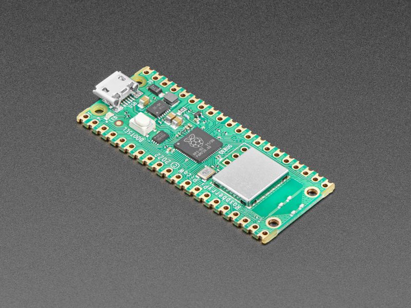
The Raspberry Pi foundation changed single-board computing when they released the Raspberry Pi computer, now they’re ready to do the same for microcontrollers with the release of the brand new Raspberry Pi Pico W. This low-cost microcontroller board features their powerful new chip, the RP2040, a...
(I know you’re using Arduino and not CP but the page talks about the bootloader and has Arduino core recommendations)
edgy ibex
stark kindle
Take a look at https://circuitpython.org/board/raspberry_pi_pico_w/ - it has so...
I followed the directions there: uninstalling the Mbed board and installing the Philhower board, that hasn't solved the underlying problem that the IDE can't see the board, even though the "RP2 Boot " device is still there.
I'm assuming that if I ever get this working, there will be a COM port that shows up, but at the current time there's nothing.
edgy ibex
Got it sorted - it's a different flow from serial USB boards, like many other Arduino boards. This one uses a UF2 bootloader. Despite the advice on the page cited, I found the Philhower board to be a failure. Every attempt to compile produces the following error:
Fatal Python error: initfsencoding: unable to load the file system codec
ModuleNotFoundError: No module named 'encodings'

Current thread 0x00001dac (most recent call first):

exit status 0xc0000409

Compilation error: exit status 0xc0000409
So I jettisoned Philhower and went back to the Arduino Mbed version. That works way better, if nothing else compilation actually succeeds. It also knows how to upload to the Pico drive that appears in Explorer, I've got a sketch running.
Can't blink the on board LED, but that's almost certainly not having the correct pin selected. Everything I've read seems to indicate that the onboard LED is pin 25, but the following sketch doesn't blink it:
#include <Arduino.h>

const int led = 25;

void setup()
{
    Serial.begin(115200);
    delay(1000);
    pinMode(led, OUTPUT);
}

void loop()
{
    Serial.println("High");
    digitalWrite(led, HIGH);
    delay(1000);
    Serial.println("Low");
    digitalWrite(led, LOW);
    delay(1000);
}
I know the sketch is running, because once it starts, the Pico shows up as COM10, and connecting the serial monitor to that port shows the alternating "High" and "Low" messages being printed.
Loss of the LED certainly isn't a dealbreaker, since I won't be using it in the final device I'm making with this board. And TBH the serial debug is infinitely more useful.
 muted gyro
edgy ibex
Got it sorted - it's a different flow from serial USB boards, like many other Ar...
muted gyro
edgy ibex
Got it sorted - it's a different flow from serial USB boards, like many other Ar...
Can't blink the on board LED, but that's almost certainly not having the correct pin selected. Everything I've read seems to indicate that the onboard LED is pin 25, but the following sketch doesn't blink it:
The onboard LED on the Pico W is actually pretty funny. Afaik it's not connected to the RP2040 at all! Instead it's connected to the GPIO of the WIFI module. The earlephilhower arduino-pico core handles that for you. The Arduino MBED core can't use the wifi module at all afaik
That's the main reason why I would definitely use the earlephilhower core
And if you compile with the earlephilhower core and get a huge memory and RAM usage for just blinking the LED, that's because it has to compile in everything it needs to talk to the wifi module (including a giant firmware blob for the wifi module). I'm not sure if it's even including the entire IPV4 stack to blink the LED.
Did you search the arduino-pico github for that error? If not, I would create an issue/discussion. I had some issue as well (with platformio instead of Arduino IDE) and earlephilhower and maxgerhardt got it fixed for me very quickly
edgy ibex
muted gyro
> Can't blink the on board LED, but that's almost certainly not having the corre...
I've posted about it on the Arduino forums already. If I can, I'll go edit the post since it looks as if the Mbed board is also a non-starter due to the lack of WiFi support. Meaning this is now down to getting the PhilHower board working. It's probably a no-brainer of a solution once I find it, just no clue what to do at the moment.
muted gyro
muted gyro
That's the main reason why I would definitely use the earlephilhower core
... there are actually others as well. For example I'm using the (now) great I2S output support. But I think it should be possible to port that from earlephilhower to mbed as a library
muted gyro
edgy ibex
I've posted about it on the Arduino forums already. If I can, I'll go edit the ...
afaik earlephilhower isn't (that) active in the arduino forums
edgy ibex
OK, thanks for the heads up on that. I just deleted the post on the Arduino forums, I'll post on the github page you linked to and see what happens.
edgy ibex
And I'm not in the least bit worried about pulling in the entire WiFi and IPV4 stack, because I'm going to need all that good stuff for the project anyway. There is a reason I got a Pico W and not just a plain Pico. 🙂 I'm just at the stage of trying to run "Blink" to make sure the workflow is correct.
muted gyro
same. I still was surprised when I saw how gigantic the blink sketch was for the first time (and I hadn't manually included any wifi stuff)😂
edgy ibex
BTW, after uninstalling the Arduino Mbed board and reinstalling the PhilHower board, the error has changed. It's now complaining about lack of an upload port, which is no great surpise because the board is in bootloader mode, and shows as a disk drive rather than a com port.
edgy ibex
That fixed it - just boot the thing NOT in bootloader mode and it did some magic via the com port that then showed and it's all good.
muted gyro
you need to follow that "uploading the first sketch" every time you buy a new RP2040. Or when you mess up and the software reset to bootloader doesn't work (for example if the Pico hard crashed, or if you messed around with USB and broke something)
Yes, normally it does some magic and automatically resets it to bootloader
oak mountain
stark kindle
There's also a <#592789347686809634> channel here where you might get some good ...
Just saw this, will take a look! thank you
oak mountain
stable forge
some projects on RPi, some projects with TensorFlow Lite: <https://learn.adafrui...
will take a look, thank you as well💪
 floral breach
1/10 times I flash a Feather M4 CAN, my USB ports die and I have to power off the PC with the physical switch on the power supply.
Any ideas?
stable forge
floral breach
1/10 times I flash a Feather M4 CAN, my USB ports die and I have to power off th...
what os? what do you mean by "die"?
floral breach
stable forge
what os? what do you mean by "die"?
Windows 10. All the connected devices turn off, LEDs and functionality. The Arduino does not re-connect, and unplugging or re-plugging USB devices does not have any effect (no device discovery "bong" sound either)
I'm connected through a USB isolator, so it's not power based. It seems to happen less when I connect through a 4port hub. Sometimes, all the devices turn off then come back on after a brief moment instead of staying off.
Since this includes my mouse & keyboard I have to crawl under the desk to turn off the PC by hand lol
stable forge
floral breach
Windows 10. All the connected devices turn off, LEDs and functionality. The Ard...
I have seen USB devices disappear like that, but on Linux, not Windows. What is the brand and model of the Windows 10 computer? Have you had this problem with other SAMD51 or other boards? Is your Windows 10 quite up to date? Do you have any utility, anti-virus, or disk monitoring programs running?
 lethal yarrow
Windows just... doesn't like serial ports, or USB devices. Try a different port.
 fathom mauve
i could use a bit of help with a pin number problem on an AtTiny1616 im working on. in my arduino code the output pins are seemingly offset. if i set pin 6 to light up a neopixel, its actually pin 11 on the breakout board that sends the pulses. i know my QFN package isnt rotated or anything, because the VCC, GND, and UPDI programming pins are all working in the right spots theyre supposed to be (pins 3, 4 and 19 respectively). so why would my coded pin output be...offset to where the actual pin being used is? does that make sense?
 leaden walrus
fathom mauve
i could use a bit of help with a pin number problem on an AtTiny1616 im working ...
leaden walrus
fathom mauve
i could use a bit of help with a pin number problem on an AtTiny1616 im working ...
what arduino core are you using?
fathom mauve
megaTinyCore
fathom mauve
yeah i am just realizing this is the SOIC package pinout, and im using the QFN package

i didnt realize they had different pin numbers
fathom mauve
leaden walrus
`6` = `PB3` = physical `8` etc.
how does this corelate? i dont understand how pin 6 in code == pb3, and that is physical 8? maybe im just not reading the pinout properly?
leaden walrus
red = arduino number, green = MCU designator, cyan = physical

cyan will vary depending on package (SOIC vs QFN etc)
green is like how the AVR architecture ref's the output
red is set by the board support package - the megatinycore
fathom mauve
oh, so when im referring to a pin in code, its not the pin number listed on the package? how would this translate to the QFN pinout i get from the datasheet, posted above? do i need to find a ''broken out pinout' like you just posted to know what physsical pins correlate to digital ones?
leaden walrus
physical pin 11 on the QFN package
pinMode(6, OUTPUT);
digitalWrite(6, HIGH);
delay(1000);
digitalWrite(6, LOW);
delay(1000);
that should show up on physical pin 11
for QFN
fathom mauve
and it does, but im still confused on how i would figure that out, without probing the pins. like fore example, if i write digitalWrite(1, HIGH); it will bring physical pin 6 high on the QFN package, but reading the pinouts, i dont understand how i would know that
leaden walrus
go by the pinout in that readme, but don't use the physical pin numbers (ignore cyan arrow)
use the green arrow
and then wherever that port/pin shows up in QFN pinout (the image you posted from datasheet)
6 = PB3 for all packages
so use datasheet pinout to determine where PB3 is for given package
datasheet mux table is also useful
fathom mauve
leaden walrus
so use datasheet pinout to determine where `PB3` is for given package
okay i think im getting it, so i would need both pinout diagrams to properly program the pins i need? like i reference the QFN pinout from the datasheet to see that physical pin 15 = PC0, and then on the megaTinyCore pinout i would see that PC0 = digital pin 10, and i would use pinMode(10, OUTPUT); in the code to output to physical 15. for example?
leaden walrus
 fathom mauve
ooooh thats a very useful table
leaden walrus
yep. probably will need to use multiple pinout tables.
fathom mauve
i had no idea the pinouts were referrential and not..actually the pins
thank you so much.
leaden walrus
np. pin naming is a very common source of confusion.
simple example above involves three! different conventions
fathom mauve
yeah its very confusing, at least at first
especially also when things like the VCC and GND are apparently in entirely different places? like the physical pins 3 and 4 on the QFN package AND datasheet match, but that apparently correlates to pin 1 and 20 on the megatinycore pinout? very confusing
plugging VCC and GND into the physical 3 and 4 pins on the chip, are also shown as pins 3 and 4 on the QFN datasheet, which works as expected, but then if im looking for the VCC and GND on the megatinycore pinout, there doesnt seem to be any connective labelling between them. i feel like i need to find an entire course on 'explaining pinouts' or something lol
leaden walrus
yes, VCC and GND are at different physical pin locations depending on package

the megatinycore generally wont have anything in code for this. it's just power. but it's up to you to route power correctly for whatever attiny package variant you are using.
fathom mauve
that MUX table is absolutely clutch lol
okay, is that a rule of thumb for chips in general? where i should only need to reference the core and datasheet pinouts for the digital pins i plan to use in code, and use the datasheet for power for the package itself?
kind of a 'use the datasheet, until you bring in code, then cross reference what the code is trying to do' situation
lethal yarrow
There's often a programming guide as well that goes into how to set up common configurations.
leaden walrus
it might be a stretch to turn that into a rule of thumb. since different core/architectures may take different approaches to things.
if you're using a pre-made board, then there should be a board specific pinout for it
lethal yarrow
And peripherals can differ significantly across chips, sometimes even chips within the same family.
leaden walrus
if you're making your own board using bare MCU's, then it's definitely a good idea to use multiple source of information. you'll be using the MCU datasheet a lot.
lethal yarrow
leaden walrus
if you're making your own board using bare MCU's, then it's definitely a good id...
Personal pet peeve: datasheets that are basically product brochures, but don't describe the peripherals in detail.
fathom mauve
leaden walrus
if you're making your own board using bare MCU's, then it's definitely a good id...
i am hitting this trouble as im venturing into custom building boards myself, where im more used to prebuilt boards and their pinouts. which might have actually made this more confusing because of that. i have been using the datashet, almost exclusively but thats clearly not the way to go.
i apparently have a lot more learning to do on how to connect the various points of reference with bare MCUs
leaden walrus
cool. i think you're just learning about new levels of info. like at the MCU/architecture level.
ready made boards abstract/hide all that
fathom mauve
exactly. and its hard to find a good source of education for that. thank you again for helping me
leaden walrus
i think you're taking best approach. just sort of dive in. and then learn as you go.
hard to find good guide like info on this. since there are so many different architectures. and things change fast too (so guides quickly get out of date).
fathom mauve
yeah that seems to be the problem in finding something relevant. i wish more READMEs had a bit of explainer about the pinouts though, the key and legends saying like 'digital pins' and 'port pins' are a certain color is great, but i could use a sentence or two about what that...means or what its referencing. lol
having datasheets is great because its just The Information™️ but i would love a little bit of context too, thank goodness this discord is a thing and i could just ask
north stream
It's also possible to look up the equivalences in the Arduino files describing the various boards.
hard whale
variant.cpp files?
 rancid tusk
Anyone have an R4 Wifi yet and used a servo with it? Even the basic servo sweep example sketch isn't working for me. The exact same code and circuit works on an uno r3, esp32, etc. so I know it's powered correctly (external power, etc. etc.). The behavior I'm seeing is almost as if the PWM target is only updated every 1 second or so, regardless of what else you're doing in the sketch.
north stream
It's a completely different CPU, there are probably going to be some rough edges for a while
rancid tusk
As an update, looks like there’s some known issues with the arduino servo library and the r4 as of now. Putting this in here in case someone else comes across the same problem. I have full faith that it’ll get worked out though! Like @north stream said, it’s a new board 🙂
floral breach
stable forge
I have seen USB devices disappear like that, but on Linux, not Windows. What is ...
Custom build, haven't tried other SAMD51 boards. Should be up to date and I don't think I have anything unusual running, don't run of the Asrock bloatware
 stable forge
floral breach
Custom build, haven't tried other SAMD51 boards. Should be up to date and I don...
stable forge
floral breach
Custom build, haven't tried other SAMD51 boards. Should be up to date and I don...
I am thinking about third-party anti-virus tools, AIDA64, etc. Some utilities that have caused problems (though not with USB): https://learn.adafruit.com/welcome-to-circuitpython/troubleshooting#bootloader-boardnameboot-drive-not-present-2978448 and below
 brittle flint
Hey team. I'm struggling a bit with a simple Arduino / ESP32 pulse counter / meter.
I have this level-shifter, which from testing and now reading the data sheet has the high-side and low-side pulled up. https://www.amazon.com/gp/product/B07F7W91LC/
I have this meter, which is Hall Effect, so it only seems to go high when pulsing and, from what I can tell, is floating otherwise: https://www.amazon.com/gp/product/B07RF49TZH/
Because it only pulses high and is never low, one would connect these with a pull-down resistor, or what I was trying to do, set the GPIO pin to INPUT_PULLDOWN. But since the level-shifter pulls everything up, I'm not confident that I can accomplish that. Are there pull-down level shifters out there or a way to properly wire this?

HiLetgo 10pcs 4 Channels IIC I2C Logic Level Converter Bi-Directional 3.3V-5V Shifter Module for Arduino

GREDIA 3/4" Water Flow Sensor Food-Grade Switch Hall Effect Flowmeter Fluid Meter Counter 1-60L/min (Pack of 2)
The pulse meters will not be the only devices connected via the level-shifter, there are also I2C devices connected to the other pins.
I suppose the right answer is, really, just use a resistive voltage divider since it won't be bidirectional.
and not use the level-shifter.
brittle flint
Whelp it works, with a 15kOhm and a 30kOhm voltage divider resister pair, but its super volatile, getting double or triple callbacks on pulses, which I guess means it has a lot of bounce. I tried to eliminate it in software, but even a timeout of almost 100 ms does not seem to clear it up, and I can expect a flow to exceed 10 Hz on the sensor.
 fallow valve
found a code one made of the fading RR Crossing Flashers with a button, I might get one those buttons you push on and it does it, now I just need to build my little LEGO RR Crossing and model it as the Safetran ones
north stream
brittle flint
Whelp it works, with a 15kOhm and a 30kOhm voltage divider resister pair, but it...
You can easily add an RC filter, since you already have the R (in your voltage divider), hanging a little capacitance on it might smooth the waveform enough to behave more reliably.
brittle flint
north stream
You can easily add an RC filter, since you already have the R (in your voltage d...
I've seen this mentioned a lot and there are lots of sketches out there for how to accomplish this. There's lots of opinions out there for sizing a voltage divider, 1k & 2k, or 10k & 20k for example, but I currently have zero points of reference for a cap size. How owuld one got about sizing that?
Maybe even just like an LS10?
north stream
It depends somewhat on the resistors in use and the time constant required. I'd probably start with 100nF or 1µF and see if it has a useful effect.
brittle flint
OK THat sounds great, I guess its time to buy a collectors set of ceramic caps.
I have the 5V input signal, a 15kOhm resistor and a 30kOhm resistor connected to ground. The 3V3 signal is between the resistors and connected to the ESP32. This is essentially in pull-down mode. The Cap would be attached between the two resistors and connected to the 3V3 rail?
north stream
Let's see, that's an effective resistance of 10kΩ, so 100nF would give a time constant of 1ms, which is probably a little short for debouncing (I generally aim for 5ms or so). I'm guessing 470nF or 1µF would be about right.
brittle flint
Why is that a 10kOhm effective resistance? They're in series. 5V Input -> 15kOhm -> 3V3 logic -> 30kOhm -> GND
i do't have an easily accessible circruit layout tool.
north stream
While they're in series, they both go to (presumably) low impedance points, so as far as an RC filter is concerned, they're effectively in parallel.
brittle flint
oh because there's a low impedance at the input side.
north stream
Right.
brittle flint
I gotchya
Still though, as for placement, the cap should be connected to the 3V3 logic and the 3V3 power?
north stream
I'd connect it from the midpoint of the resistors (basically the output to your 3V3 logic) to ground
 trim furnace
Hi folks, does anyone know the process of adding your own custom board variant to the arduino ide. I have made an custom esp32 s3 board with different features on.
north stream
I haven't done it in a while, but the general process I used was to start with an existing board that was similar, copy those files and modify them to describe the details of my board.
trim furnace
(boards.txt entry)
I think the error has to do with me using the CP2102N to programme the ESP32 S3, I currently don't want to use OTG, so no need for the tinyusb bootloader
don't think I need a variant.cpp file
north stream
It seems like a mismatch between the #defines used for things like ARDUINO_USB_MODE and the header file. Some setups will set a variable like that to 0 or 1, which works with #if, but others will define a symbol for one case, and nothing for the other, which may be the case here, so it ends up with #if and no expression. Note I've also seen #ifdef used similarly. Perhaps removing the tinyusb headers has left some things not set up?
trim furnace
north stream
It seems like a mismatch between the #defines used for things like `ARDUINO_USB_...
I've tried adding #define ARDUINO_USB_MODE 0
#define ARDUINO_USB_CDC_ON_BOOT 1 to the pins_arduino.h
but I get a similair error
north stream
What error specifically?
 stray rapids
TFT Screen Calibration
 wind drift
Question:
I have 10 LEDs and 10 push buttons.
The LEDs are playing a sequence (colors/intensity etc.) which use some delays in the code.
I want to be able to "switch" to another sequence when pressing a button. (each button would trigger a new sequence)
Is that doable? At the moment I have the problem that when I press the button while the delay is active it does not register the push
north stream
Yes, it's doable. Basically instead of using delays, you just loop and check input and whether it's time yet to do something. Details here https://learn.adafruit.com/multi-tasking-the-arduino-part-1
wind drift
north stream
Yes, it's doable. Basically instead of using delays, you just loop and check in...
Thanks - hmm seems like a lot of work if I have many delays in my code
north stream
Yes, when I get to that point, I'll often refactor my code so I have a routine I call instead of delay(), and roll up repeated code into loops.
wind drift
OK trying that now.
I have one issue where I have a delay of 2000 ms at the end of a function though
north stream
Why would you delay at the end of a function?
wind drift
it basically plays an LED sequence and then pauses for a short time. Then plays another sequence
muted gyro
"Delay at end of function" is just the same as "delay before the start of the next function"
you might have to restructure a bit
while(true){
  delay(1000);
  doSomething();
}
//is the same as
delay(1000);
while(true){
  doSomething();
  delay(1000);
}
I had to add this middle delay to make it REALLY the same. But if you don't care if something starts immediately or after delay you can keep it out
north stream
The same general approach works: ```arduino
#define A_SHORT_TIME 2000
static unsigned long do_next_sequence;
void loop() {
unsigned long now = millis();
if (now > do_next_sequence) {
// start next sequence
do_next_sequence = now + A_SHORT_TIME;
}
 sharp turret
north stream
The same general approach works: ```arduino
#define A_SHORT_TIME 2000
static un...
sharp turret
north stream
The same general approach works: ```arduino
#define A_SHORT_TIME 2000
static un...
Keep in mind that code is not millis() rollover safe. do_next_sequence will rollover before millis() does.
which will result in some errors when millis() does rollover. (which, in most cases won’t matter, but is a reason not to do the “increment a variable and compare” approach.)
(and to expand on that. the incremented variable rolls over at the time of the increment. so until millis() gets around to rolling over, that if-statement fails.)
  previous_millis = millis();
  // code to do …
}```
handles roll-over correctlyBut that's more subtractions!
sharp turret
Yes, but they are complimented with twos. And that makes them nicer.
north stream
Complimented or complemented? 😆
 coarse furnace
Hello!
I have problems uploading code to my adafruit esp32 feather boards. They have had this problem since I got them about 1 year ago and I have asked for help here before but no one could help me diagnose the problem enough to either solve the problem or know for sure that the boards are broken somehow.
Would someone like to help me with this? I am not with my computer right now but will be about 3 hours from now!
stable forge
coarse furnace
Hello!
I have problems uploading code to my adafruit esp32 feather boards. The...
Please circle back when you are you at the computer and say what board you are using, what you are doing, and what is not working. Or you can open a thread in the forums if you prefer: https:forums.adafruit.com, where paid support people hang out, but the lead time may be longer. This place is community support, though some staff are here also.
coarse furnace
stable forge
Please circle back when you are you at the computer and say what board you are u...
I am by my computer now!
I have this board: https://www.adafruit.com/product/3405
I am trying to upload any code in any type of whay at this point, but my dream would be to install WLED from this website: https://wled-install.github.io/
The thing that is not working is to upload the code. I do not know exactly what in the upload that is not working though.

Aww yeah, it's the Feather you have been waiting for! The HUZZAH32 is our ESP32-based Feather, made with the official WROOM32 module. We packed everything you love about Feathers: built ...
muted gyro
I tried WLED out once on another board (ESP8266). For me only the second (esptool) method from here worked: https://kno.wled.ge/basics/install-binary/ Have you tried that?
coarse furnace
muted gyro
I tried WLED out once on another board (ESP8266). For me only the second (esptoo...
I have not actually. Will look into that!
coarse furnace
muted gyro
I tried WLED out once on another board (ESP8266). For me only the second (esptoo...
Hmm I get stuck on the first step. How exactly do I download esptool.py? because the URL it tells me to click takes me to no steps I can follow.
muted gyro
click on documentation in that first link
yeah I remember it being definitely harder than the web installer (which didn't work)
leaden walrus
@coarse furnace have you installed the CP2104 drivers?
https://learn.adafruit.com/adafruit-huzzah32-esp32-feather/using-with-arduino-ide
coarse furnace
leaden walrus
<@424337547603345409> have you installed the CP2104 drivers?
<https://learn.adaf...
Yes, I know I tried installing them before but back then I don't know if I did it correctly. How can I verify that I have the correct driver?
leaden walrus
what OS are you using on the host PC? windows/mac/linux?
coarse furnace
windows
leaden walrus
can check device manager and look for the COM port to show up
coarse furnace
Yes it shows up
 leaden walrus
yep, that looks good. so it's COM6
can you provide more info on what happens in the Arduino IDE when you try to upload a sketch
coarse furnace
yes and in the properties it sais that it works properly
coarse furnace
leaden walrus
can you provide more info on what happens in the Arduino IDE when you try to upl...
It was a while ago I used the arduino IDE, I use visual studio now. But I know that it times out after "Connecting.....-----.....-----....."
muted gyro
also try the arduino IDE. (I know totally different platform and totally different issue but still: I had an issue where uploading to RP2040 worked using the Arduino IDE but didn't work using Platformio)
leaden walrus
can you try again now?

 leaden walrus
hmm...that all looks generally ok
just to double check the feather, it's not a V2 version?
https://www.adafruit.com/product/5400
coarse furnace
I only have one button on the feather board also. So alll the workarounds of holding the "BOOT" button doesn't work on my board
yea no its this one: https://www.adafruit.com/product/3405
Aww yeah, it's the Feather you have been waiting for! The HUZZAH32 is our ESP32-based Feather, made with the official WROOM32 module. We packed everything you love about Feathers: built ...
coarse furnace
 leaden walrus
ooo..photo! awesome. thanks.
coarse furnace
Just to let you also double check that it’s the correct board and settings
leaden walrus
did you every hook up anything to the feather pins?
coarse furnace
No, just the usb port when connecting to the computer. I also haven't had anything to connect
I also have 2 of thoues, and none of them work
leaden walrus
have you tried a 2nd PC?
coarse furnace
I have. but not scientiffically. Just a friend who tried uploading to my adafruit boards and managed with one of them. But that was a breakout board with a broken GPIO button XD https://www.adafruit.com/product/4172

Squeeeeze down your next ESP32 project to its bare-bones essential with the Adafruit HUZZAH32 Breakout. This breakout is basically the 'big sister' of our HUZZAH 8266, but instead of ...
His computer was not able to upload to any of the feather boards. Same as my computer
But my three esp32 devkit V1 from china works first time when trying to upload.
Ok this happes to the other feather board:
 leaden walrus
weird. but that one at least was able to open the COM port and talk to the ESP32
it got the chip id, etc.
if you now go back to the other feather, does its behavior repeat? or does it fail differently?
that is, do you get this again?

or something else?
coarse furnace
Yeah I get the exact same as before when going back to the first one
so they both give different errors
And switching back again to the second one gives the same as that one got before aswell.
leaden walrus
different USB cables have been tried?
coarse furnace
Not now, will do that. But I know that this cable works for all my other boards.
leaden walrus
ok, worth trying, since USB cable issues are unfortunately super common 😦
it's obviously not a charge cable, since it's getting at least some data traffic
stable forge
is it plugged directly into a port, or through a hub?
The ESP32 uses a fair amount of current, so if you're getting flakey behavior make sure you are plugging your console cable into either a motherboard USB port or a powered USB hub. Don't use the 'extra' USB port on your monitor or keyboard.
leaden walrus
^^ good info. a marginal USB cable could cause that behavior also. (current limit issue)
stable forge
(I have one of these but can't find it at the moment 😦 )
leaden walrus
(USB cable? hopefully you tossed it)
coarse furnace
Ok I have tried another cable on both of them but the exact same error occurs. I also don't have a powered USB hub, I just use the ports on the side of my computer. Have 3 ports
I can connect 5V to it from the pins if that would supply more power?
leaden walrus
no. that's ok. if it were a USB cable issue, might still fail, but would expect different behavior.
also surprised the behavior is repeatable. and different. different but repeatable.
very weird
do you have more than two of these?
coarse furnace
no I have thouse other breakout boards
coarse furnace
sure
leaden walrus
thanks. can ping me with a link to the post once up. i'll follow up over there.
stable forge
@cater I found my identical board
leaden walrus
same here. did some testing. no issues. arduino. esptool. all work as expected.
stable forge
did you test on Windows?
leaden walrus
no. linux.
stable forge
i have a Windows box to test on, looks like older Arduino, 1.9.x. Also
leaden walrus
i'm still on 1.8 also for daily driving (1.8.19)
esptool.py v4.2.1 <- what was used for CLI testing
coarse furnace
@leaden walrus https://forums.adafruit.com/viewtopic.php?t=203468
stable forge
@leaden walrus I installed Arduino 1.8.19 fresh on a Windows 10 box. I allowed it to install all the drivers. I did not install the CP210x driver specifically. Below is the driver version. I added the extra URL for Espressif BSP, installed version 2.0.10 (2.0.11 was getting checksum errors for me). Upload Blink, no problem.

Check version of driver and BSP. Might consider cleaning out the USB devices with Uwe Seiber tool, but I don't think that's it.
I have an old board that has an old module on it. That photo looks like a newer module.
leaden walrus
@coarse furnace thanks for post. can you check your driver info similar to what danh shows above. you mention using a PL2303 in the forum post. so worth verifying driver being used.
coarse furnace
I am afk right now but can send it later, but from just a few minutes ago when checking the properties of the COM port I think I remembered it saying silicon labs CP210x, but could not remember the version and stuff
leaden walrus
ok. i'll post some stuff in the forums. we can continue there. since you're afk, not worth continuing here.
my guess is CP2104 driver is OK, based on device manager appearance
 odd fjord
When I use the Adruino IDE 2 (2.2.1) IDE, my serial output converts alll "9"s to "-"s. I am running this on a Mac (M1). Has anyone else seen this and do you know how to fix it?

The output is normal with the old IDE or with a terminal session like tio or screen.
odd fjord
With tio ```[06:41:15.998] Waiting for tty device..
[06:41:26.039] Connected
Sending to rf95_reliable_datagram_server
got reply from : 0x2: response from node 2 2
Sending to rf95_reliable_datagram_server
got reply from : 0x2: response from node 2 3
Sending to rf95_reliable_datagram_server
got reply from : 0x2: response from node 2 4
Sending to rf95_reliable_datagram_server
got reply from : 0x2: response from node 2 5
Sending to rf95_reliable_datagram_server
got reply from : 0x2: response from node 2 6
Sending to rf95_reliable_datagram_server
got reply from : 0x2: response from node 2 7
Sending to rf95_reliable_datagram_server
got reply from : 0x2: response from node 2 8
Sending to rf95_reliable_datagram_server
got reply from : 0x2: response from node 2 9
Sending to rf95_reliable_datagram_server
got reply from : 0x2: response from node 2 10
Sending to rf95_reliable_datagram_server
got reply from : 0x2: response from node 2 11
Sending to rf95_reliable_datagram_server
@odd fjord can not easily recreate
 odd fjord
Thanks for trying…
leaden walrus
@odd fjord your example has some casting going on though. it could be related to that.
meh. dunno. 🤷
 odd fjord
meh, too...

It has always been this way for me with IDE2....
And I don't see a simple way to get a - from a 9 ...
leaden walrus
 odd fjord
sigh...
leaden walrus
do you also get 57 from above?
 odd fjord
 odd fjord
I tried changing the default font from Monaco to Monospaced -- no help
I think I hav a 1.9.x -- and it works fine there/
1.8.19
leaden walrus
got a non-macOS setup to try on?
odd fjord
I'll try that in a little while -- Need to get it set up.
Thanks for the help and suggestions.
leaden walrus
np. weird issue 🙂
odd fjord
I'll post to the arduino forum.
leaden walrus
could also try with a totally different MCU, just to help verify its something with mac/UI
odd fjord
Same result with an Arduino R4 ....
leaden walrus
probably a macOS "feature" then
leaden walrus
good that it sounds like its at least a known feature 🙂
 pine bramble
i use a pca 9685 and arduino uno but my code has no errors but the servo wont move who can help me ?
leaden walrus
pine bramble
i use a pca 9685 and arduino uno but my code has no errors but the servo wont mo...
can you post photo of setup?
pine bramble
Here u go


 pine bramble
Sure
leaden walrus
basic connections look OK, btw
 inland gorge
pine bramble
Here u go
inland gorge
pine bramble
Here u go
I don’t see the power LED lit on the PCA9685 board. Maybe your batteries are dead?
pine bramble
The light only lights up when i plug the usb in
 severe thistle
Hi everyone,
I am trying to flash the Portenta H7 using a binary file I generate via dfu-utils. I am unable to figure out a way to set the Portenta to bootloader mode via software. I came across this which talks about using dfu-utils to flash but nothing about how to set it to bootloader mode. There is also [this] (Solved: STM32H747: How to start the system boot loader via... - STMicroelectronics Community) but I cannot understand this one and I don't think a complete solution is given either.
Would appreciate any help.
inland gorge
severe thistle
Hi everyone,
I am trying to flash the Portenta H7 using a binary file I generat...
Does this page help at all? https://docs.arduino.cc/tutorials/portenta-h7/updating-the-bootloader
pine bramble
leaden walrus
try running an i2c scan real quick just to make sure the PCA is seen
so i went to the arduino ic2 scanner page and i uplauded that code
 tired goblet
I have a Sparkfun Pro Micro clone that uses an RP2040 and loads UF2 firmwares. I'm trying to figure out which board I should configure in the IDE to generate the right file.
I tried Raspberry PI Pico and Arduino Nano RP2040 Connect without success. They generate UF2 files, but the board is not running them so I suppose the target is bad.
inland gorge
tired goblet
I have a Sparkfun Pro Micro clone that uses an RP2040 and loads UF2 firmwares. I...
You can probably use a standard Pico UF2 and have it work. The main problem is different boards use different flash chips, and if SparkFun used a sufficiently different one from Pico, its UF2 will have that. In my experience though, most RP2040 clone makers use Pico-compatible flash chips
tired goblet
inland gorge
You can probably use a standard Pico UF2 and have it work. The main problem is ...
I can use the circuitpython UF2 without issues. I believe this means that I have a compatible flash chip. Correct?
tired goblet
inland gorge
You can probably use a standard Pico UF2 and have it work. The main problem is ...
My bad, I was using printf statements instead of Serial.println. Everything is good now.
muted gyro
tired goblet
I have a Sparkfun Pro Micro clone that uses an RP2040 and loads UF2 firmwares. I...
Are you using the offical arduino(-mbed) core?
I recommend to use https://github.com/earlephilhower/arduino-pico instead
maybe it even has correct board definitions already
(it even has printf I think)
tired goblet
muted gyro
Are you using the offical arduino(-mbed) core?
I recommend to use https://github...
yes, I'm using the official mbed board library. I'll give a try to the one you've mentioned.
pine bramble
@leaden walrus what do i do with the ic2 scanner
 sage lichen
Trying to set up the tft_espi library with an Inland ESP32 dev board. Where should I find (or specify) which pins will be used for what functionality? I found this link https://github.com/Bodmer/TFT_eSPI/blob/master/User_Setup.h#L139-L147 and tried following the recommended pinout for an ESP32 dev board but I think it was for the official one and not the Inland one. Is there a way to just specify which pins i'm using for each function? Also how do I figure out the actual pin number for a given pin? I followed the attached diagram but I'm not sure if the pin numbers match up (for the esp8266 dev boards I remember it didn't match up all the time)


GitHub
Arduino and PlatformIO IDE compatible TFT library optimised for the Raspberry Pi Pico (RP2040), STM32, ESP8266 and ESP32 that supports different driver chips - Bodmer/TFT_eSPI
stark kindle
sage lichen
Trying to set up the tft_espi library with an Inland ESP32 dev board. Where shou...
The default pins will vary by the kind of ESP32, not so much by the board. It will be the same for all ESP32's (ESP32-S2's, ESP32-S3's, etc will have their own default pin numbers). Fortunately this footprint specifies GPIO numbers, so you won't need to try to sort out labels specific to the board. The default SPI pins for vanilla ESP32s are MISO - 19, MOSI - 23, SCK - 18, SS - 5.
You can map SPI pins to almost any available GPIO pins by calling begin(CLK_PIN, MISO_PIN, MOSI_PIN, SS_PIN) on the SPI object. Pins 34 and up are input-only and should be avoided.
Vanilla ESP32s have 4 SPI controllers - SPI0 and SPI1 are used internally to talk to memory. The one referred to as SPI in Arduino is really SPI3 (also called VSPI). Oddly SPI1 is really SPI2.
Sometimes board definitions will define different pins, which can be confusing. As long as you chose unused pins and call SPI.begin() giving the pins numbers you should be fine.

GitHub
Arduino core for the ESP32. Contribute to espressif/arduino-esp32 development by creating an account on GitHub.
sage lichen
stark kindle
The default pins will vary by the kind of ESP32, not so much by the board. It wi...
So how do I tell TFT_eSPI which pins I am using for everything?
stark kindle
sage lichen
So how do I tell TFT_eSPI which pins I am using for everything?
In the User_Setup.h file - the library's documentation should go over this.
sage lichen
stark kindle
In the User_Setup.h file - the library's documentation should go over this.
Ah ok thx
leaden walrus
pine bramble
<@337989520962093057> what do i do with the ic2 scanner
what showed up in the arduino serial monitor when the i2c scan sketch was run? (can paste here)
sage lichen
What is the proper way to clear the screen when using the TFT_espi library? I need to draw a progress bar so the previous screen needs to be cleared before I can draw the next frame. I am currently using the fillScreen method to just make everything black before I draw the next frame, but that is causing some really bad flickering. Wondering if there is a better way
 gilded swift
sage lichen
What is the proper way to clear the screen when using the TFT_espi library? I ne...
gilded swift
sage lichen
What is the proper way to clear the screen when using the TFT_espi library? I ne...
Probably resetting the screen
sage lichen
gilded swift
Probably resetting the screen
How do I do that? 😅
gilded swift
Good question, I thought they exposed a reset function.. guess not
Looks like they just fill the screen with TFT_BLACK
sage lichen
I see tft.init but not sure if that will be good to call each frame
Yeah that was what I am trying but it flickers so much
sage lichen
Maybe I'm just trying to run at too high of a refresh rate
sage lichen
gilded swift
Looks like they just fill the screen with TFT_BLACK
Figured it out. Turns out I needed to use a sprite and 8 bit color
gilded swift
Ah, makes sense
north stream
I think one of the examples does that
leaden walrus
pine bramble
<@337989520962093057> what do i do with the ic2 scanner
run the sketch and look at the resulting output in the serial monitor. verify the expected address shows up.
 cobalt owl
I have a Monochrome 1.3" 128x64 OLED graphic display - STEMMA QT / Qwiic that I've connected to my Arduino R4 Wifi via a STEMMA QT cable, with the arduino connected and powered via USBC on my PC. Everything lights up, there's a green status light on the OLED display - but none of the example code works. I'm just starting out with playing with arduino - and just want to get something on the screen to confirm that it's working. I did run a I2C scanner on my arduino but all I get is the scanning now message and no failure or end state. Help greatly appreciated as I'm not sure whether to open a support ticket or not.
inland gorge
cobalt owl
I have a `Monochrome 1.3" 128x64 OLED graphic display - STEMMA QT / Qwiic` that ...
I suspect the issue you're having is that the Qwiic connector is Wire1 in Arduino and not Wire. (Wire is for the SDA/SCL pins up near the RESET button). I'm not sure which sketch you're using, but if you're using the Adafruit_SSD1306 library, try making this your setup line:
Adafruit_SSD1306 display(SCREEN_WIDTH, SCREEN_HEIGHT, &Wire1, OLED_RESET);
Ah that was it @inland gorge cheers - but when you say it's 'Wire1 in arduino' is that because the library is used for boards other than Arduino, just wondering if there's anything else I need to be aware of?
inland gorge
cobalt owl
Ah that was it <@352910176736772096> cheers - but when you say it's 'Wire1 in ar...
ah sorry I misspoke. I mean in the Arduino IDE. You could use that screen on the Arduino R4 WiFi, but instead of using the Arduino IDE, you could use Micropython / CircuitPython / Renesas ARM SDK, etc.
 rough torrent
I have this code running on an Arduino Nano: (8-bit device obviously then)
uint64_t board;
uint64_t scanBoard();
board = scanBoard();
This assignment will take multiple clock cycles right? And therefore it will be interruptable? (by an interrupt)
I'm looking at the assembly dump (which is making my head spin lol) and there are sections of code that look like this:
 79e:    60 92 3c 01     sts    0x013C, r6    ; 0x80013c <board>
 7a2:    70 92 3d 01     sts    0x013D, r7    ; 0x80013d <board+0x1>
 7a6:    80 92 3e 01     sts    0x013E, r8    ; 0x80013e <board+0x2>
 7aa:    90 92 3f 01     sts    0x013F, r9    ; 0x80013f <board+0x3>
 7ae:    10 92 40 01     sts    0x0140, r1    ; 0x800140 <board+0x4>
 7b2:    10 92 41 01     sts    0x0141, r1    ; 0x800141 <board+0x5>
 7b6:    10 92 42 01     sts    0x0142, r1    ; 0x800142 <board+0x6>
 7ba:    10 92 43 01     sts    0x0143, r1    ; 0x800143 <board+0x7>
So my guess it does take multiple cycles?
(unfortunate that code syntax highlighting does not support assembly 😦 )
north stream
I would expect scanBoard() (whatever it does) to take a bunch of cycles. The assignment would take a few cycles as well to copy 8 bytes, one at a time.
 lyric pivot
rough torrent
I have this code running on an Arduino Nano: (8-bit device obviously then)
```c...
lyric pivot
rough torrent
I have this code running on an Arduino Nano: (8-bit device obviously then)
```c...
Basically yeah, as you've found with the assembly being pulled apart. The atmega328 doesn't have any hardware support for 64 bit integers and has to run extra software to perform that functionality, which could hypothetically be interrupted yes
 silk token
anyone here use platformIO willing to help with a strange issue? I have this stupid issue where it keeps opening main.ino and I type a ton of changes in it, instead of main.cpp without realizing, then after 30 minutes I figure out why the compiled code isnt doing as expected on the arduino. I have been making project workspaces out of my old workspaces before I started using platformIO so they all have main.ino files in them. I don't really notice when it's doing it, I think its happening when I alt-tab back to the vscode window? I will try to observe more closely to determine when exactly it reopens that tab for main.ino
I know for a FACT its re-opening that tab because I ragequit yesterday after closing it twice over the course of three hours losing lots of work. I swear to god I am not losing my mind
edit: yeah, it seems to be happening when I alt-tab back to it I think, WHY IS THIS HAPPENING?!?
 rugged plank
Does anyone have any advice on how to format an array in a POST payload?
cedar mountain
rugged plank
Does anyone have any advice on how to format an array in a POST payload?
Do you mean in JSON format? I don't think there's any "native" data formats for POSTs in general.
rugged plank
Not sure what the right terminology is, I am not used to HTTP requests. Ended up figuring it out, thanks though!
 winter willow
NOOB QUESTION: So I'm trying to do the Dark Tower Mini Project (https://github.com/mighty-bean/DarkishTower/tree/main/src) and I have a Feather S2 connected to my Mac with the arduino IDE showing that it's connected to the board : Adafruit Feather ESP32-S2 on /dev/cu.usbmodem06559FBEAE681 and a new Sketch in the IDE with the board selected, But I'm stuck on what to do next. The code is on github but I don't know how to move it to the board and have it run. Can anyone point me to a tutorial or info on how to get the board to run Arduino cpp code?
Just as a test I loaded the Blink example and clicked the |> button but it returned "GDB executable "/Users/wopr/Library/Arduino15/packages/esp32/tools/xtensa-esp-elf-gdb/11.2_20220823/bin/arm-none-eabi-gdb" was not found. Please configure "cortex-debug.armToolchainPath" or "cortex-debug.gdbPath" correctly"
TLDR: How to get the Adafruit Feather ESP32-S2 to run Arduino code


 north stream
winter willow
TLDR: How to get the Adafruit Feather ESP32-S2 to run Arduino code
north stream
winter willow
TLDR: How to get the Adafruit Feather ESP32-S2 to run Arduino code
The learn guide should cover it https://learn.adafruit.com/adafruit-esp32-s2-feather/arduino-ide-setup
 winter willow
I followed it. Put the board in bootloader mode, selected the port (Adafruit Feather ESP32-S2 on /dev/cu.usbmodem01). try to run the Blink sketch and it returns : GDB executable "/Users/wopr/Library/Arduino15/packages/esp32/tools/xtensa-esp-elf-gdb/11.2_20220823/bin/arm-none-eabi-gdb" was not found. Please configure "cortex-debug.armToolchainPath" or "cortex-debug.gdbPath" correctly"
Verified the sketch (it's the blink example) and tried uploading and got this:
Writing at 0x002f58e9... (100 %)
Wrote 155104 bytes (101152 compressed) at 0x002d0000 in 1.6 seconds (effective 792.4 kbit/s)...
Hash of data verified.
Leaving...
WARNING: ESP32-S2 (revision v0.0) chip was placed into download mode using GPIO0.
esptool.py can not exit the download mode over USB. To run the app, reset the chip manually.
To suppress this note, set --after option to 'no_reset'.
Failed uploading: uploading error: exit status 1
Ok, being a noob I didn't realize I had to hit the -> arrow key, but it does the same thing as the menu 'upload' does so... lesson learned. Ok it's uploaded and I unplug and replugin the board and the sketch is running. the led is blinking! Progress!
Not sure why my 'Debug' [> button gives me the config error though.
Regardless, now I wonder how I get the .cpp code from the github in it. The code isn't in a 'sketch'.
muted gyro
winter willow
Ok, being a noob I didn't realize I had to hit the -> arrow key, but it does the...
to be honest, I always just click upload and it compiles and uploads. Maybe that you have to press verify first is an issue with Arduino IDE 2 for mac and ESP32 🤔 https://github.com/espressif/arduino-esp32/issues/8029
GitHub
Board esp32 Device Description euno esp32 https://item.jd.com/10036937330081.html Hardware Configuration EUNO 原理图 2021-7-26.pdf Version v2.0.7 IDE Name Arduino IDE 2.0.4 Operating System windows 10...
muted gyro
winter willow
Regardless, now I wonder how I get the .cpp code from the github in it. The code...
it is, just kinda complicated 😄
https://github.com/mighty-bean/DarkishTower you need to go to the main page of the repo
Then click the green "code" button, then "download zip". That way you get all files
winter willow
I've got it loaded into the IDE now... .learned the .ino file is loadable but it's not in a directory structure the the ide wants (ie... in a main). So I got that setup and now going through and adding libraries and fixing the compile complaints
muted gyro
Then you need to unpack that zip. And I think you need to rename the folder to "main". So that you have the structure like this:
/main/src/buch of stuff
/main/main.ino
/main/Readme.md
/main/...
Maybe you could also rename the main.ino to DarkishTower.ino 🤔
heh you were faster 😄
winter willow
Ok got it to compile and upload! Now I have to wire up the TFT and sound board to see if it's working. Thanks for the help!!
I'll have to dig into the debug issue: That thread recommeded this video https://www.youtube.com/watch?v=hJSBTFsOnoA

The USB feature of the new ESP32 chips is handy. Unfortunately, it is not easy to use because the information is hidden. This video shows how everything works and how you must set up the Arduino IDE to exploit the USB functionality. I promise it will save you a lot of frustration and time. And it is the basis for a future video about simple debu...
wind drift
Question:
I want to do the following with a battery powered arduino:
- press a button
- Arduino starts and runs through some functions
- Once finished it turns the whole system off to save power
What would be the best way to do this?
north stream
As always, "best" depends on what your parameters are. One popular approach is to have a MOSFET control the power, so the button turns it on, then it pulls itself on via a resistor to stay on, until the Arduino uses a GPIO to turn it back off.
north stream
I assume the idea is to push the button again to restart it. If you want something to run periodically and shut down, you could use something like https://www.adafruit.com/product/3435

With some development boards, low power usage is an afterthought. Especially when price and usability is the main selling point. So what should you do when it's time to turn around and ...
 rain dust
north stream
I assume the idea is to push the button again to restart it. If you want someth...
rain dust
north stream
I assume the idea is to push the button again to restart it. If you want someth...
Then you could use the RESET pin, but he really said „power it off”.
And afcours the lpt is a good selution
stark kindle
winter willow
Writing at 0x002f58e9... (100 %)
Wrote 155104 bytes (101152 compressed) at 0x002...
I know you got it already, just wanted to add that you can safely ignore this error. There's some magic that the uploader usually does over USB to reset the ESP32 that it can't do with the ESP32-S2 or S3 so you have to reset the ESP32 yourself to get the program to run. On other ESP32s that happens automatically. Nothing actually failed; Arduino's error message there is just plain wrong.
WARNING: ESP32-S2 (revision v0.0) chip was placed into download mode using GPIO0.
esptool.py can not exit the download mode over USB. To run the app, reset the chip manually.
To suppress this note, set --after option to 'no_reset'.
Failed uploading: uploading error: exit status 1
wind drift
rain dust
But if the Arduino is off, how are you going to power it on again?
Yep it would be a single button. And a single press to start the whole process
So after it ran through the code it completely turns off using 0 power
 dry quiver
You can try this too https://www.adafruit.com/product/1400 . I had mine hooked up to a transistor and a GPIO pin on a Pi to even switch it on as part of a sequence.

The Adafruit Push-button Power Switch is a tidy little design that lets you control a DC power source using an everyday tactile button. The breakout uses a latching analog circuit that is ...
 storm pebble
Quick question, I'm helping someone with an ESP32-S2-Kaluga-1 kit (from Adafruit I'm pretty sure), and the screen seems to be reversed? Like, text is written mirrored, and I'm fairly certain the colors are messed up too. Anyone ever dealt with something like this?
Should be the ST7789 driver chip, using the official adafruit libraries and everything
fallow valve
What stuff I'll need to build a nice Arduino based Oscilloscope so I can use it to test simple stuff with it then buying an expensive one
north stream
fallow valve
What stuff I'll need to build a nice Arduino based Oscilloscope so I can use it ...

Build Electronic Circuits
This Arduino oscilloscope is perfect if you need an oscilloscope right now, but all you have is an Arduino. It's simple and quick to build.
If you want a standalone one (that doesn't need a host computer to display the waveforms), you could use an approach like https://circuitdigest.com/microcontroller-projects/diy-mini-oscilloscope-using-arduino-nano
fallow valve
well I do wish to make a case with everything inside of the arduino powered oscillo
north stream
Someone here did something like recently to come up with an all-in-one test instrument box. It came out really nice.
 steep swift
Been toying around with a diy project idea and was wondering if I could get feedback on what process might be the right way to go
I want to build my own film camera shutter speed tester
As they get older the timings can slip which can effect exposure
What would yall use to time a shutter opening at 1/2000th of a second?
My first idea was just one of the sensors that some cheap night lights use but a bit of research leads me to believe they don't poll fast enough
 pallid sage
I assumed the truly cheap ones would be sensor then transistor, I could imagine a capacitor in there to reduce flapping though
north stream
steep swift
Been toying around with a diy project idea and was wondering if I could get feed...
Many night lights use a cadmium sulfide sensor, which is fairly slow. However, photodiodes are fast and fairly easy to use.
steep swift
Yeah I'm thinking of a photodiode or a phototransistor, currently researching the differences
Photodiodes seem to be faster
Which is ultimately the main idea
north stream
You can think of a phototransistor as a photodiode with gain and (sometimes) an additional bias input.
steep swift
As someone who primarily used pi pico's with micro/circuitpython, would you say setting up a photodiode is a bit of a task if I used an arduino pro micro?
I'm sure I can find example diagrams and such online
And would you say there's a specific type or model of photodiode that would suit this application?
lethal yarrow
north stream
You can think of a phototransistor as a photodiode with gain and (sometimes) an ...
You can, because that's literally what it is. Plus some slightly different doping.
north stream
steep swift
As someone who primarily used pi pico's with micro/circuitpython, would you say ...
It's pretty straightforward. While you do need a "reverse bias", that's just the logic supply and a resistor. This page gives the basics. https://www.ee-diary.com/2021/08/photodiode-light-detector-with-arduino.html#

ee-diary
How to use Photodiode as a light sensor with Arduino
However, the ADC may be too slow for a 1/2000 measurement, so you might need to boost the signal enough to drive a digital input.
You could probably use a phototransistor, transistor booster, or a comparator (like an LM339) to get a logic level compatible signal that could drive a digital GPIO.
You can also buy logic-output photodetectors (Optek OPL530 is one possibility) that are plenty fast and easy to use.
steep swift
north stream
You can also buy logic-output photodetectors (Optek OPL530 is one possibility) t...
This is great info, thanks!
 tardy zealot
I'm trying to implement the following code for a Feather M4 CAN. I don't seem to see an interrupt pin available for the Feather M4 CAN according to the diagram? Or am I blind and am I missing something?
const int buttonPin = 2; // Pin connected to the button
volatile int buttonPressCount = 0;
volatile unsigned long buttonPressStartTime = 0;
volatile unsigned long buttonPressDuration = 0;
void setup() {
pinMode(buttonPin, INPUT);
attachInterrupt(digitalPinToInterrupt(buttonPin), buttonISR, CHANGE);
Serial.begin(9600);
}
void loop() {
// Your main loop code here
// You can use the buttonPressCount and buttonPressDuration variables as needed
}
void buttonISR() {
if (digitalRead(buttonPin) == HIGH) {
// Button is pressed down
buttonPressStartTime = millis();
} else {
// Button is released
buttonPressDuration = millis() - buttonPressStartTime;
if (buttonPressDuration > 50) { // Ignore small bounces
buttonPressCount++;
Serial.print("Button pressed ");
Serial.print(buttonPressCount);
Serial.print(" times for ");
Serial.print(buttonPressDuration);
Serial.println(" ms");
}
}
}
 cedar mountain
tardy zealot
I'm trying to implement the following code for a Feather M4 CAN. I don't seem to...
cedar mountain
tardy zealot
I'm trying to implement the following code for a Feather M4 CAN. I don't seem to...
Pretty much all GPIOs should be interrupt-capable, I think, so the diagram probably doesn't bother labeling them.
leaden walrus
^^ that. in this case, the interrupt is an internal feature of those pins. a little different than a dedicated interrupt pin coming from something like a sensor, etc.
tardy zealot
cedar mountain
Pretty much all GPIOs should be interrupt-capable, I think, so the diagram proba...
Ah thank you! I'll assign it to Pin 5 and find out if that's the case.
 opal iris
Hello all, why Arduino IoT cloud is showing "offline" even though I have connected the device to internet.
Sometimes, its very difficult to bring the device back to online status. How can I solve this issue. Right now, I am logging all the sensor value to google spreadsheet and it is working fine but parallelly I want the data to be shown on IoT dashboard as well but the cloud is showing "offline". Please help me...

 fast jacinth
Hi all, I am trying to get a pair of RP2040 RFM featherwings to act as a transmitter reciever pair as per this tutorial (https://learn.adafruit.com/feather-rp2040-rfm95/using-the-rfm-9x-radio). When I upload Feather9x_TX.ino or Feather9x_RX.ino RadioHead examples they both get stuck at the "Waiting for packet to complete..." portion and will never finish executing. Does anyone know what could be causing this issue, or have a better tutorial they could point me to?
Thanks

same thing when I comment out everything but the RP2040 pins
 fallow valve
https://projecthub.arduino.cc/siliconvalley4066/arduino-lcd-touch-shield-dual-channel-oscilloscope-33c1ab - this can work for me since I can build one and see if I can put it inside a enclosure case but it says it's up to 100khz and I need about 15 mhz and above
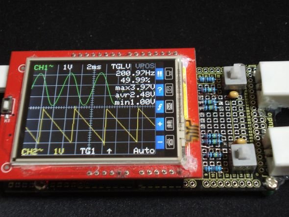
projecthub.arduino.cc
Arduino LCD touch shield dual channel oscilloscope with equivalent time sampling
north stream
fallow valve
https://projecthub.arduino.cc/siliconvalley4066/arduino-lcd-touch-shield-dual-ch...
For an Arduino based scope, 100kHz is about the best you're likely to do without some serious outboard hardware. What do you need 15MHz for?
fallow valve
north stream
For an Arduino based scope, 100kHz is about the best you're likely to do without...
Service manual of the atari 2600 says you'll need a 15mhz oscillator for testing the console when it needed
north stream
Huh, I don't remember that. I thought there was a single 3.58MHz oscillator (for the colorburst, for NTSC 2600s anyway) that was divided down for the CPU clock. I don't remember anything using 15MHz. But I haven't looked at that service manual in a while (the last 2600 I fixed, I didn't even need the service manual, I just replaced the electrolytic capacitors and cleaned the contacts and it was fine)
In any case, you presumably wouldn't be scoping the oscillator signal
I do enjoy repairing vintage things like vacuum tube gear and 2600s more than modern stuff.

 livid osprey
fallow valve
Service manual of the atari 2600 says you'll need a 15mhz oscillator for testing...
livid osprey
fallow valve
Service manual of the atari 2600 says you'll need a 15mhz oscillator for testing...
Oscillator or oscilloscope?
north stream
Heh, I suspect you're right there. It's amazing what you can do with a limited bandwidth oscilloscope.
wind drift
Quick question - I am trying to play some audio with a small speaker I have from my arduino. I have simple sound clip playing already but it is very low volume.
I read that I need to use a transistor to use it as a sound amplifier - is that correct?
I have 2n 7000, 2n 3904, CTBC 337 ~40 LE laying around
are these suitable? Or do I need something else?
Also 2n 2222A ~1726, LM35,
north stream
Yeah, those are suitable. Some useful information here https://learn.adafruit.com/transistors-101
 shell niche
the Adafruit motor shield for arduino v2.3 has the ability to micro step and also simultaneously control (start and stop at same time with differing travels) 2 stepper motors with accel/multi stepper right?
Im having issues with the steppers not stopping at the same time
Dm me if you have experience with multistepper + the Adafruit shield. I’d appareciate it 😔
north stream
shell niche
the Adafruit motor shield for arduino v2.3 has the ability to micro step and als...
Basically the board doesn't have any smarts, it just does what you tell it. The usual approach is to have the software calculate the speeds necessary to have the motors finish at the same time and then loop through the steps at the required rates to implement it.
shell niche
north stream
Basically the board doesn't have any smarts, it just does what you tell it. The...
im using multistepper which should have simultaneous control but im not sure why thye aren't ending at the same time
north stream
Weird, that's what multistepper is supposed to do
shell niche
life is tough
edgy ibex
Getting an answer to this isn't a deal breaker, it's just a "nice to know". If I'm using the standard AdaFruit_NeoPixel driver, I know that interrupts are disabled during strip.show(), and therefore millis() doesn't update.
I can account for that because I can determine the number of milliseconds spent in strip.show() from the length of the strip:
#define BITS_PER_PIXEL 24
#define BITS_PER_MS    800.0f
int const totalBits = stripLength * BITS_PER_PIXEL;
float msToDisplay = (float) totalBits / BITS_PER_MS;
OK so far. However, does the "last" millisecond interrupt happen immediately after interrupts are re-enabled at the end of strip.show()? I tend to think so, because most processors I've studied in this regard (8080 / Z80) can defer an interrupt that happens during a momentary period when interrupts are disabled. This is more or less a necessity, otherwise timing will drift in the long term due to regular interrupt activity, e.g. keyboard and/or serial I/O.
I can (and plan to) study this empirically, but it'd be nice to get a second opinion from someone with a bit more knowledge. I'm using an ESP32 S2 if it makes a difference.
 crystal yacht
I love this community. Where else would you have two people talking about an atari 2600 oscillator... I feel at home here. These are my peoples.
 inland gorge
edgy ibex
OK so far. However, does the "last" millisecond interrupt happen immediately af...
inland gorge
edgy ibex
OK so far. However, does the "last" millisecond interrupt happen immediately af...
generally if you start worrying about timing drift, you need some off-board timing reference (RTC chip, GPS, etc) as you'll never be very accurate just "dead-reckoning" it based off of CPU clock cycles. Even if you just count clocks and had no interrupts, the crystals used on MCU boards are like 20 ppm accuracy (0.002%), i.e. a few seconds per day
north stream
Alternatively, you might be able to use an on-board one if there's another timer available.
 grave mortar
okay I feel like I'm losing my mind, https://www.arduino.cc/reference/en/language/functions/communication/wire/onrequest/ for wire.onRequest() I want to sit on the i2c bus at 0x55 and listen for the controller to send a request, but I don't get how I send the ack bit and then read if the request is read or write and then what the request is.
Like I can see that the code runs when the request comes but how do I work with the data in the request?
The Arduino programming language Reference, organized into Functions, Variable and Constant, and Structure keywords.
rough torrent
grave mortar
okay I feel like I'm losing my mind, https://www.arduino.cc/reference/en/languag...
I've been working on code that makes an Arduino Nano as a peripheral on the I2C bus, maybe this code will be a bit helpful.
uint8_t registerAddr = 0;

...

void setup() {
  ...
  Wire.onReceive(onWireReceiveEvent);
  Wire.onRequest(onWireRequestEvent);
}

...

void onWireReceiveEvent(int count) {
  registerAddr = Wire.read();
}

void onWireRequestEvent() {
  const uint8_t boardOffset = 0x90;
  if (registerAddr == boardOffset - 1) {
    Wire.write((uint8_t)boardChanged);
    boardChanged = false;
  } else if (registerAddr >= boardOffset && registerAddr < boardOffset + 8) {
    Wire.write(packedBoard.bytes[registerAddr - boardOffset]);
  } else {
    Wire.write((uint8_t)0);
  }
}
First the Arduino receives a byte that will be the "address". The request tells the Arduino to send a byte that corresponds to the address. In my case, it's sending either a flag whether the board changed at 0x8F, or the states of reed switches from 0x90 to 0x97. If you did an "I2C dump", this would show up as a peripheral with 255 registers, most of them being 0.
It only demonstrates being a read-only device though...
grave mortar
OMG THIS IS EXACTLY WHAT I NEED THEN!! I may need to add in "writes" but this is a huge start
Thank you so so much, I'm trying to replace a i2c device I don't have access too, with this and the data sheet I should be able to emulate the right responses!
I didn't know you could have two functions with the same name, is there a reason for the two functions?
oh I need to got to bed lol
rough torrent
I would do "writing to a register" like this: (untested just typed up now)
int16_t registerAddr = -1;

void onWireReceiveEvent(int count) {
  if (registerAddr == -1) {
    registerAddr = Wire.read();  // We received the address
  } else {
    const uint8_t byteToWriteAtAddr = Wire.read();  // We already have the address, receive the byte
    ...
    registerAddr = -1;
  }
}

void onWireRequestEvent() {
  if (registerAddr == -1) {
    Wire.write((uint8_t)0);  // No address set
  } else {
    const uint8_t byteToReturnAtAddr = ... // Using registerAddr determine the byte to return to the controller
    Wire.write(byteToReturnAtAddr);
    registerAddr = -1;
  }
}
void onWireReceiveEvent(int count);
void onWireRequestEvent();
Receive and Request look similar if that is what you are talking about
rough torrent
grave mortar
oh I need to got to bed lol
Me too haha
grave mortar
👀 okay hmm I'm sure I'll have more questions when I sit down to implement but this is a huge help! thank you.
rough torrent
np!
muted gyro
Has anyone here used I2S, PWM Audio, or ADC input on RP2040 (Arduino-Pico) and run into the issue that it lead to crashes, it getting stuck or just not inputting/outputting any data or playing no sound? Especially when stopping and restarting.
(I don't need any support. Rather, if you have or had this issue, please ping be because I might have a fix and it would be great to have some more test cases.)
 tame merlin
Hi folks. I am new to Arduino and I am struggling with a display issue. I am using an AMOLED display on a ESP32-S3 (lilygo board). When I create a sprite and push colours to that sprite, everything is fine. When I push a sprite to another sprite. The pushed sprite colours are messed up. For a while I thought it was the board, or display but a single sprite works fine. I know this will be 'basic' but my googlefu isn't coming up with anything. void draw(){ background.fillSprite(TFT_WHITE); background.setTextColor(TFT_BLACK,TFT_WHITE); background.setTextDatum(1);//centre top background.drawString(String(col),120,40,4);//need to learn about fonts. Size and fontstyle. dial.fillSprite(colourarray[col]); dial.pushToSprite(&background,60,208,TFT_WHITE); lcd_PushColors(60, 208, 120,120, (uint16_t*)dial.getPointer()); background.pushSprite(0,0); lcd_PushColors(0, 0, 240,536, (uint16_t*)background.getPointer());
stark kindle
edgy ibex
Getting an answer to this isn't a deal breaker, it's just a "nice to know". If ...
This isn't answering your question about interrupts, but it's not necessarily the case that disabling interrupts causes millis() to not update. It depends on the platform. On the ESP32 disabling interrupts doesn't stop millis() from changing.
On the ESP32, millis() derives its value from esp_timer_get_time()
which, following it through a couple of calls, ends up at systimer_hal_get_counter_value, which reads a 64 bit counter in an interrupt-safe manner and returns its value. This counter is part of the CPU hardware; it increments whether or not interrupts are enabled.
It's easy to confirm with a simple program
Also, adafruit_neopixel doesn't disable interrupts on the ESP32 as it uses the RMT peripheral to drive the LEDs.

Gist
Demonstrate ESP32 millis() incrementing while interrupts disabled - esp32-millis-interrupt.cpp
GitHub
Arduino library for controlling single-wire LED pixels (NeoPixel, WS2812, etc.) - adafruit/Adafruit_NeoPixel

GitHub
Espressif IoT Development Framework. Official development framework for Espressif SoCs. - espressif/esp-idf

GitHub
Arduino core for the ESP32. Contribute to espressif/arduino-esp32 development by creating an account on GitHub.
 hardy crypt
https://www.adafruit.com/product/4750
Are there any way to store a fingerprint on an sd card connected to an arduino using the fingerprint sensor? Since on the documentation on that fingerprint, it only says that the fingerprints are stored in the fingerprint's internal flash memory

Secure your project with biometrics - this adorably tiny, all-in-one, optical fingerprint sensor will make adding fingerprint detection and verification super simple. It's extremely ...
Perhaps the only way is to enroll a finger, read it from the arduino and then manually save it on the micro sd card that I've connected to the arduino?
inland gorge
hardy crypt
https://www.adafruit.com/product/4750
Are there any way to store a fingerprint o...
from the ZFM-20 user manual, it looks like there are commands to upload and download fingerprint images or templates, but that's not reflected in the Arduino library currently.
hardy crypt
inland gorge
from the ZFM-20 user manual, it looks like there are commands to upload and down...
What about the circuitpython library? And what are the commands? Can't I pass these ttyl commands manually perhaps?
inland gorge
from this document: https://cdn-shop.adafruit.com/datasheets/ZFM user manualV15.pdf It look like the "GenImg" command reads a finger image and "UpImage" / 'DownImage" sends to /recieves from to the computer? Then there are similar commands for finger models (called "Chars" in the manual it seems)
grave mortar
rough torrent
np!
This question is for everyone but figured I'd ping you, I am just trying to make sure I understand reading i2c registers and have htis code going. for some reason, it's only returning 255? I can't figure out what's wrong.
`#include <Wire.h>
void setup() {
// put your setup code here, to run once:
Wire.begin();
Serial.begin(115200);
}
void loop() {
// put your main code here, to run repeatedly:
#define CHIP_ADDRESS 0x55
#define REGISTER_ADDRESS 0x06
Wire.beginTransmission(CHIP_ADDRESS);
Wire.write(REGISTER_ADDRESS);
Wire.endTransmission();
Wire.requestFrom(CHIP_ADDRESS, 1); // We want one byte
uint8_t val = Wire.read();
Serial.println(val);
delay(1000);
}`
rough torrent
Bad I2C wiring/high bus capacitance is my guess
(sorry I'm in a phone making debugging a bit difficult lol)
grave mortar
no worries, I'm able to use a scan sketch to find the i2c device but this just keeps failing
grave mortar
It's weird because it was working yesterday but I made some changes and in reverting back I must be missing something
 final yacht
Can you diff the version that works and the version that doesn't work? Or if you have no record of the changes, try to reproduce the changes from memory. Even if you can't remember the precise changes, by going over the code from this different perspective you may spot what you missed earlier.
grave mortar
final yacht
Can you diff the version that works and the version that doesn't work? Or if you...
Yeah no record sadly. I basically broke my original code into functions so that I could check two addresses at once and it just stopped
But the working code was from the previous day so maybe it's my mc
leaden walrus
is the device still showing up in scan? and at address 0x55?
 elfin lance
has anyone run in to issues where without updating any packages or verions that they can no longer porgram a QT PY ESP32-S3 NOPSRAM, I can program my C3 just fine and my S3 was working fine till just today. Now i am getting this error. I have rebooted and tried reinstalling the board lib with no change.
inland gorge
elfin lance
has anyone run in to issues where without updating any packages or verions that ...
Are you using Arduino IDE v1.8.x? If so, try just quitting it and restarting. I've hard weird compilation gremlins fixed by that
elfin lance
inland gorge
Are you using Arduino IDE v1.8.x? If so, try just quitting it and restarting. I'...
i am, and i have tried that as well. its very strange because i can see the board still running my code from the last time i programmed it, serial console is working just fine. After I posted that message i was able to also program a QTPY ESP32 as well as my C3, just not this one. is it possible to borked the bootloader but the code still runs?
inland gorge
elfin lance
i am, and i have tried that as well. its very strange because i can see the boar...
another trick that seems to help is to go to the Board Manager and switch boards to some entirely other architecture (like Arduino Uno), then switch back to the board you actually want. These seems to clear out some build cache
elfin lance
inland gorge
another trick that seems to help is to go to the Board Manager and switch boards...
no luck on that either, i had though of that but didnt think about the arch type. hmm.
inland gorge
@elfin lance hmmm. looks like you're on Linux, did you update your Python recently? It looks like esptool.py is the thing actually having problems. I'm unclear how Arduino on Linux deals with Python upgrades
oh another idea: do you have any other program that's grabbing that serial port?
like tio or screen
elfin lance
inland gorge
<@230938658407055362> hmmm. looks like you're on Linux, did you update your Pyt...
Nope, so it kinda just fixed itself after multiple times of unplugging and plugging. I did hold down the boot button while plugging it in one of the times. So, i dono. Thanks for the suggestions.
inland gorge
elfin lance
Nope, so it kinda just fixed itself after multiple times of unplugging and plugg...
sigh yeah. glad you got it working. 🙂
wind drift
´this might be a dumb question but I am trying to use this max98357 breakout board with my arduino nano. But I am getting a compile error. Is the nano not compatible with this board?
https://learn.adafruit.com/adafruit-max98357-i2s-class-d-mono-amp/arduino-wiring-test-2

Adafruit Learning System
Add digital-quality audio with a class D amplifier for easy sound!
muted gyro
wind drift
´this might be a dumb question but I am trying to use this max98357 breakout boa...
The microcontroller must be capable of outputting I2S. Not all can do that. It usually requires special I2S hardware in the MCU. Btw I2S has nothing to do with I2C.
And the library you're using has to support I2S of your specific microcontroller.
Are you using an "Arduino Nano"? Like just "Arduino Nano" and nothing else in the name? Not "Arduino Nano 33 BLE", "Arduino Nano ESP32" and so on?
The "Arduino nano" uses the ATmega328 MCU, which can't do I2S.
Really doing something with I2S actually requires quite a bit of performance. I'm currently using I2S audio on an RP2040 which runs at over 8 times the clock speed, has 132 times more RAM, over 50 times the flash and is 32bit instead of 8.
=> I think you need a different board with a faster microcontroller that specifically supports I2S.
There are also other ways of playing audio on microcontrollers that don't involve I2S. But they have (different) limitations than that I2S amp board.
wind drift
got it - thanks!
yeah I just need my speaker to by louder 😄
at the moment it's very quiet
muted gyro
How are you driving the speaker now?
muted gyro
then your arduino outputs PWM, right? 🤔
In terms of audio quality and volume I really like that I2S Amp. Quality is definitely good enough for music. And with a 7 or 8cm 8W or 30W speaker, at full volume it's way louder than how I normally listen to music, etc.
If you can't use I2S then maybe you can use an amplifier like this https://www.adafruit.com/product/5647 But please double check

The Adafruit STEMMA Audio Amp is a super small mono amplifier is surprisingly powerful - able to deliver up to 2.5 Watts into 4-8 ohm impedance speakers. Inside the miniature chip ...
north stream
wind drift
yeah I just need my speaker to by louder 😄
Just driving it with PWM signals from the Arduino? You can boost it with a transistor.
wind drift
I tried that earlier but couldn't get it to work somehow
north stream
Something like this?
 wind drift
yep - but let me try again with those values
@north stream yep I built it again with those values. (But I am using a 3904 transistor in case that matters?)
It seems to be the same volume - maybe even quieter than without it
and same thing for the 2n2222 transistor

not sure if this picture helps
 feral grove
I'm trying to use the 1.3" 128x64 Adafruit 1306 OLED board with an Adafruit ESP32-S2 Feather via STEMMA cable. The power light is green and the Test Bed scanner sees the display at 0x3D, and i'm using the ESP32-S2 I2C power enable hokey-pokey routine, and the code gets past the display.begin(...) step but I can't get it to display using the Adafruit example . Using Arduino IDE v2.1.1 and all libraries are up to date. What's the next debug step?
leaden walrus
feral grove
I'm trying to use the 1.3" 128x64 Adafruit 1306 OLED board with an Adafruit ESP3...
the i2c power should be taken care off (on by default) if using the latest ESP32 BSP. no need for extra code in user sketch. are you running the OLED example mentioned in guide?
https://learn.adafruit.com/monochrome-oled-breakouts/arduino-library-and-examples#run-demo-1757237
feral grove
yes
More correctly, the example with the library
OK removed the hokey pokey code and it works ... So it looks like I turned I2C off 🤣 Thanks
feral grove
leaden walrus
the i2c power should be taken care off (on by default) if using the latest ESP32...
OK removed the hokey pokey code and it works ... So it looks like I turned I2C off 🤣 Thanks
leaden walrus
yay! cool - glad it was something simple.
feral grove
leaden walrus
yay! cool - glad it was something simple.
Well the fact that the display.begin(...) routine succeeded with I2C power disabled is funky 🤔
leaden walrus
it's probably a good idea to add some delay in setup() before trying to init the display
the OLED probably wants a couple 100 msec after being powered before talking to it over I2C
i'm testing here, and the delay() seems to be required
i can get a nothing-on-display behavior otherwise
resetting the feather seems to cycle the I2C power, so does a new sketch upload
void setup() {
  Serial.begin(9600);
  delay(200);

  // SSD1306_SWITCHCAPVCC = generate display voltage from 3.3V internally
  if(!display.begin(SSD1306_SWITCHCAPVCC, SCREEN_ADDRESS)) {
    Serial.println(F("SSD1306 allocation failed"));
    for(;;); // Don't proceed, loop forever
  }
that's working well though
feral grove
I had 5 secs to wait for serial to stabilize since while (!Serial) doesnt work on the s2. And, the scan routine implements the hokey pokey routine
feral grove
leaden walrus
that's working well though
I had 5 secs to wait for serial to stabilize since while (!Serial) doesnt work on the s2. And, the scan routine implements the hokey pokey routineanyway ,,, weirdness aside I can now proceed .. thanks again
leaden walrus
while (!Serial); should work. it worked for me. i was doing that too as part of testing.
here's where the BSP takes care of the I2C power, for ref:
https://github.com/espressif/arduino-esp32/blob/e0657db0f0d4cfe9320744faf2507123790cf56c/variants/adafruit_feather_esp32s2/variant.cpp#L32C1-L46
feral grove
leaden walrus
`while (!Serial);` should work. it worked for me. i was doing that too as part o...
on an ESP32-s2 Feather?
leaden walrus
yep
void setup() {
  Serial.begin(9600);
  while (!Serial);

  Serial.println("HELLO WORLD");
}

void loop() {
}
while (!Serial); Hangs forever for me ???
I can put print in the while loop and it prints ???
leaden walrus
so maybe it's not waiting on your setup?
feral grove
leaden walrus
so maybe it's not waiting on your setup?
Something strange is going on
you using Windows 11?
leaden walrus
i'm on linux
feral grove
Will the Arduino IDE run on a Pi? If so I'll load it on Pi I have and try
leaden walrus
i think so? used to, but been a while since i've looked into that. not sure of current state/support.
feral grove
leaden walrus
i think so? used to, but been a while since i've looked into that. not sure of c...
When I have some time I'll try it
lethal yarrow
The ESP8266 has a single core, so it can't service an ISR while executing the main program simultaneously.
 willow star
I was wondering if somebody could answer a question about i2c adressing a matrix of neotrellis(es?)
i am making a matrix of 8 for a midi controller, is it better to address them left to right, top to bottom and incrementally?
leaden walrus
generally doesn't matter. whatever works best for easy coding.
The panels don't have to have consecutive address #'s, they just have to be unique.
ok thanks!
 uneven gorge
Please be gentle with me I'm new here... Finally managed to get my computer (Windows 10) and Arduino (2.1.1) to "see" my Flora, but neither of them can communicate with it. I've downloaded two different sets of drivers, and neither of them appears to be what my computer is using anyway (not 100% sure).
Is there someone here who can point me in the right direction? I've been googling and restarting and uninstalling and reinstalling and such for like 2.5 hours now
livid osprey
uneven gorge
Please be gentle with me I'm new here... Finally managed to get my computer (Win...
Have you followed this guide to add your boards to the Arduino IDE? https://learn.adafruit.com/add-boards-arduino-v164/setup

Adafruit Learning System
Easily add support for Adafruit boards to Arduino v1.6.4!
uneven gorge
livid osprey
Have you followed this guide to add your boards to the Arduino IDE? https://lear...
Yes 🙂
livid osprey
Does your computer respond at all to you plugging or unplugging the board?
If not, one possibility is you’re using a charge only cable, and you should try a different cable?
uneven gorge


It shows up as an unidentified COM3 in Arduino, so I manually change it to the Flora option, and it does that. I am just trying a basic blink program to troubleshoot.
Yep brand new cable did it. I had to go digging through my water room to find it 😂
livid osprey
Hmmmm, I wonder if there’s an issue with the boot loader. @uneven gorge do you have any other Arduino devices?
uneven gorge
livid osprey
Hmmmm, I wonder if there’s an issue with the boot loader. <@161997899100717057> ...
I do, but the esplora has been my latest tinker toy for Arduinos
Anyway all good since I managed to find another cable
livid osprey
Oh, is it all better now?
uneven gorge
Yep. Thanks for the assist. :3
wind drift
Got another question for playing music using an SD card.
What exactly is the difference between using these 2 modules?

ACEIRMC 5pcs YX5200 DFPlayer Mini MP3 Player Module MP3 Voice Decode Board Supporting TF Card U-Disk IO/Serial Port/AD Compatible for Arduino

ANMBEST 10PCS Micro SD SDHC TF Card Adapter Reader Module with SPI Interface Level Conversion Chip for Arduino
The first one has some extra components at the bottom
muted gyro
wind drift
Got another question for playing music using an SD card.
What exactly is the dif...
The first one is a Dfplayer (or a clone of it) Here's its documentation: https://wiki.dfrobot.com/DFPlayer_Mini_SKU_DFR0299
It's a serial mp3 player. Everything from reading the SD-card, to decoding audio, processing, volume control, DAC, Amp is done on the DFPlayer board. You only talk to it over serial and tell it what to do. Like "play file xyz.mp3", "change volume to 5", etc.
That means your microcontroller can be really slow as it doesn't have to actually do anything relating to audio. But you're limited to the features that the Dfplayer provides.
The second thing is just an SD-Card breakout board. It can't do any audio stuff by itself. You can use an SD-Breakout to store and access whatever files you want on the SD-card. Of course you can also read audio files from it. But to actually play the audio files you need to decode them either on your microcontroller or with a separate codec chip. And then to output it to a speaker you need to use the PWM/DAC of your microcontroller (and maybe add an amplifier/transistor to it) or use a separate DAC and amplifier.
This second option is a bit more complicated, and it requires way more processing resources on your microcontroller. But you can add more features (if your processing speed allows it). For example, I don't think you can actually access the files on the DFplayers SD-card (for example if you wanted to make a music player and data logger in one device)
wiki:DFRobot Mini Mp3 Player is an extremely low cost MP3 module that can be interfaced with Arduino. It supports common audio formats such as MP3, WAV and WMA.
wind drift
Ah got it - thanks!
Basically I just turn some leds on/off and play a few audio clips after the led sequence
muted gyro
I think the DFplayer would be easier to use then
wind drift
Will try that
muted gyro
be aware ofth equality issues with this kind of cheap stuff
Maybe also interesting:
Kinda like option 2 in my text above: If I understand correctly it works like this: The SD-card is connected to your MCU, the audio file is read from the card and then sent to the codec chip which handles everything. So kinda the best of both worlds maybe. Low processing requirement, easy to use adafruit library and you still have access to the SD-card. Can even do recording. https://www.adafruit.com/product/3357
Works similarly to the DFplayer except from adafruit, premium, and sadly only 16MB of flash instead of an sd-card:https://www.adafruit.com/product/2220

Bend all audio files to your will with the Adafruit Music Maker FeatherWing! It's a fun-size version of our Music Maker shield for Arduino! This powerful wing features the ...

Would you like to add audio/sound effects to your next project, without an Arduino+Shield? Or maybe you don't even know how to use microcontrollers, you just want to make a sound play ...
@mystic trail 
@wind drift
wind drift
Thanks will check those out too. I will try it with the first one as I have one of those lying around
 slate pendant
Hey I'm trying to kinda make a library for Arduino:
I've already created most of it but I'm struggling with function pointers.
Here's what I have:
- class SMBus (Expands on the Wire lib with some quality-of-life additions and changes)
- class Battery (Implemented according to the SMBus SmartBattery Specification, has functionality to interface with smart batteries)
SMBus smart batteries take over the bus and become a Master when they have an alarm warning. they send it to the Host with a command that is equal to their bus address.
I want to receive this AlarmWarning Message by having the Library user register a handler when instantiating the battery.
My Idea is:
- SMBus class provides (static) method for adding a handler and registers it's own Handling function via Wire.onReceive() (the function first reads the entire message and then passes the buffer to all registered handling functions)
- User defines function according to
void (*AlarmWarningHandler)(uint8_t, byte)with the first parameter being the address of a battery, the second being a bool-bundle of 8 Alarm flags.
(The user shall provide it's own logic what to do if certain flags are set, basically just a switch case) - User passes handler as parameter when instantiating a battery. It allows multiple batteries to have the same handler or differing ones but the handler shall have access to the address of the battery that sent it.
basically this is my current class layout but I can't get it to compile:
class SMBus {

  // Up to 8 Receive handlers
  static bool (*Handlers[8])(char[], int);
  static uint8_t HandlerCount;

  static void HandlerQueue(int length) {
    char buf[length];
    uint8_t received = Wire.readBytes(buf, length);
    if (received < length) {
      Serial.println("Unexpected transmission end in message from device!");
    }

    for (uint8_t i; i <= HandlerCount; i++) {
      if (Handlers[i](buf, length)) {
        Serial.println("[Dbg] (" + String((uint8_t) Handlers[i], HEX) + ") calling receive handler at address \"" + String((uint8_t) Handlers[i], HEX) + "\":");
      }
    }
  }

public:
  static void addReceiveHandler(bool (*Handler)(char[], int)) {
    Wire.onReceive(HandlerQueue);

    Handlers[HandlerCount] = Handler;
    HandlerCount++;
  }
}

class Battery {
SMBus SMB;
void (*awh)(uint8_t, byte);

bool ReceiveHandler(char buf[], byte length) {
    if (length == 2) {
      if ((byte) buf[0] == address) {
        // call awh with error bytes!
        awh(address, buf[1]);
        return true;
      }
    }
    return false;
  }

public:
  uint8_t address;

  Battery(SMBus SMBus, uint8_t Address, void (*AlarmWarningHandler)(uint8_t, byte)) {
    SMB = SMBus;
    address = Address;
    awh = AlarmWarningHandler;
    SMB.addReceiveHandler(ReceiveHandler);
    }
}
the problem is that I cannot pass non-static functions to addReceiveHandler()
north stream
I don't think addReceiveHandler() should be static.
wind drift
muted gyro
The first one is a Dfplayer (or a clone of it) Here's its documentation: https:/...
hmm I got it half working now
When I tap GND wire to IO_1 it plays the sound
But I can't get it to work with the RX/TX and my arduino
I have it correctly connected with the 1k resistor
ah nvm
had 10 and 11 flipped
slate pendant
north stream
I don't think addReceiveHandler() should be static.
there can only be one "instance" of the SMBus tho - it's an expansion on Wire like I said. maybe the whole class should be static
slate pendant
north stream
I don't think addReceiveHandler() should be static.
even if not static, error still this:
argument of type "bool (Battery::*)(char *buf, byte length)" is incompatible with parameter of type "bool (*)(char *, int)
muted gyro
slate pendant
there can only be one "instance" of the SMBus tho - it's an expansion on Wire li...
Some boards have multiple "Wire" instances
slate pendant
ohh good to know!
I'll keep the architecture more like Wire then - Still need to pass the member function tho
 fringe ledge
Hello everyone, I hope this is the right place to ask. I have a adafruit circuit playground express and the TFT gizmo. I am trying to figure out what pins exactly I should be using in my arduino sketch.
I am using one of the examples from the ST77XX library and it uses the following pins. The screen's backlight turns on but nothing is shown on the screen itself. Does anyone have any ideas?
#define TFT_RST       -1 // Or set to -1 and connect to Arduino RESET pin
#define TFT_DC        1
#define TFT_BACKLIGHT PIN_A3 // Display backlight pin```the code compiles and there is nothing obviously wrong in the code. I wonder if I'm missing something else about the physical configuration. The 12 oclock label is also aligned with the microusb port on the playground express. Is there anything else I could be missing?
muted gyro
hopefully helpful link: https://learn.adafruit.com/adafruit-tft-gizmo/pinouts#spi-display-pins-3041879 There's also an Arduino example in that guide
fringe ledge
muted gyro
hopefully helpful link: https://learn.adafruit.com/adafruit-tft-gizmo/pinouts#sp...
thank you. That is the guide I followed that allowed me to at least turn on the backlight but it still doesn't print anything to the screen 😦
muted gyro
This yellow message sounds suspicious like it might be the cause of your problem:
The SPI SCK and MOSI pins are not the default SPI pins for the CircuitPlayground Express or the CircuitPlayground Bluefruit.
but tbh I really don't know how to fix/handle that
fringe ledge
muted gyro
This yellow message sounds suspicious like it might be the cause of your problem...
thank you. I'm pretty sure this has something to do with the issue. I'll try the software pins solutions and try different things
I figured it out in case anyone needs to know: you absolutely have to use "software SPI pins". I don't undesrtand this very well, but in the 'graphicstest_tft_gizmo" example from the Adafruit_ST7789 library:
#include <Adafruit_ST7789.h> // Hardware-specific library for ST7789
#include <SPI.h>

// Because of the limited number of pins available on the Circuit Playground Boards
// Software SPI is used
#define TFT_CS        A6
#define TFT_RST       -1 // Or set to -1 and connect to Arduino RESET pin
#define TFT_DC        A7
#define TFT_BACKLIGHT PIN_A3 // Display backlight pin

// You will need to use Adafruit's CircuitPlayground Express Board Definition
// for Gizmos rather than the Arduino version since there are additional SPI
// ports exposed.
#if (SPI_INTERFACES_COUNT == 1)
  SPIClass* spi = &SPI;
#else
  SPIClass* spi = &SPI1;
#endif

// OPTION 1 (recommended) is to use the HARDWARE SPI pins, which are unique
// to each board and not reassignable.
// Adafruit_ST7789 tft = Adafruit_ST7789(spi, TFT_CS, TFT_DC, TFT_RST);

// OPTION 2 lets you interface the display using ANY TWO or THREE PINS,
// tradeoff being that performance is not as fast as hardware SPI above.
#define TFT_MOSI      PIN_WIRE_SDA  // Data out
#define TFT_SCLK      PIN_WIRE_SCL  // Clock out
Adafruit_ST7789 tft = Adafruit_ST7789(TFT_CS, TFT_DC, TFT_MOSI, TFT_SCLK, TFT_RST);```in this example only the OPTION 2 works.
fringe ledge
muted gyro
This yellow message sounds suspicious like it might be the cause of your problem...
thank you for replying. You made me look in the right place!
muted gyro
great work that you figured it out! 🥳
 prisma sand
Hello, I need some help please, I'm working with Seeed Studio nRF52840 SENSE, and I want to enable serial bluetooth (classic bluetooth not BLE) with it, is anyone can help me with an Adafruit libary to do so?
and thanks in advance ❤️ .
cedar mountain
prisma sand
Hello, I need some help please, I'm working with Seeed Studio nRF52840 SENSE, an...
I didn't think the Nordic chips could do classic Bluetooth. Are you sure this is possible with this hardware?
prisma sand
Yes it supports both Classic bluetooth and BLE
And I was able to do so with circuitpython but I want to work with it with Arduino
cedar mountain
Ah, cool, that's my useful learning for the day. 😁
stark kindle
prisma sand
Yes it supports both Classic bluetooth and BLE
And I was able to do so with cir...
Nordic says that the nRF52840 doesn't support Bluetooth Classic. I've only seen BLE support in CircuitPython. Can you share the library you used with it to do Bluetooth Classic in CircuitPython?
slate pendant
slate pendant
ohh good to know!
I'll keep the architecture more like Wire then - Still need to...
hi - I'm still stuggling with the problem outlined above this message. help would be great ^^
north stream
Which problem? Designing the class? Using the class? Compiling the code? All three? Something else?
slate pendant
north stream
Which problem? Designing the class? Using the class? Compiling the code? All...
designing
I know how I want to use it (wich i tried to outline in the linked messages) but I can't get the code to understand me ^^'
stark kindle
slate pendant
Hey I'm trying to kinda make a library for Arduino:
I've already created most of...
The problem here is that you're passing a class method as a function pointer. A class method isn't a simple function. You have to invoke a class method on an object. So when you call
SMB.addReceiveHandler(ReceiveHandler);
you're not also passing the Battery object that ReceiveHandler would be associated with. And when you try to call it , you're using it as a simple function pointer without any object, which can't work (even if you could have passed the method, which the compiler didn't let you do).
if (Handlers[i](buf, length)) {
Where's the Battery in that?
There are a few ways you might handle this. There's a discussion of it in this Stack Overflow question.

Stack Overflow
How do I obtain a function pointer for a class member function, and later call that member function with a specific object? I’d like to write:
class Dog : Animal
{
Dog ();
void bark ();
}...
slate pendant
stark kindle
The problem here is that you're passing a class method as a function pointer. A ...
Omg now I see it!!
The invisible this parameter 🤦🏽
Thank you!
Now I'll have to choose how I can write the SMBus class independantly of the Battery class but still have interop.
avoiding global variables like a snake pit
prisma sand
stark kindle
[Nordic says that the nRF52840 doesn't support Bluetooth Classic](https://devzon...
adafruit_ble
livid osprey
prisma sand
adafruit_ble
Isn’t that Bluetooth LE? I don’t see any Bluetooth Classic references in its docs…
stark kindle
livid osprey
Isn’t that Bluetooth LE? I don’t see any Bluetooth Classic references in its doc...
Yeah, there is no Bluetooth Classic there and according to Nordic, the nRF52840 doesn't support Bluetooth Classic, so I think there's some confusion here.
livid osprey
prisma sand
Hello, I need some help please, I'm working with Seeed Studio nRF52840 SENSE, an...
There is BLE UART if you need wireless serial on the nrf52, but for true continuous Bluetooth Classic serial, you will need different hardware.
See https://learn.adafruit.com/bluefruit-nrf52-feather-learning-guide/ble-uart-controller for one example of an nrf52840 running a BLE UART service if that’s of interest to you.

Adafruit Learning System
Get started now with our most powerful Bluefruit board yet!
 red pine
I’ve got a project using an ItsyBitsy 32u4 5v and two LED strips (one with RGB 2020 NeoPixels and the other with RGBW 5050 NeoPixels).
I’m trying to set it up with several custom-made lighting animation effects that I can toggle with an IR remote, and I want at least some of the effects to be able to play on both strips at the same time.
Is the best way to be able to use the same effect on two different strips simultaneously to make my effects into classes and then create unique instances for each strip?
north stream
You'll want a unique instance for each, but I don't think you'd need to wrap them in classes.
red pine
north stream
You'll want a unique instance for each, but I don't think you'd need to wrap the...
I guess it's a question of where I want the duplicative code; either multiple headers and cpp files, or multiple creations of class objects. I'm working on the method of turning each effect into a class and then creating multiple instances, and it's working with my first few test effects. We'll see how it goes as I add more...
north stream
I may be misunderstanding, but my thinking is you're using an existing library, and its source and header files, and you'd just create two instances of its class, one for each strand.
 cold lagoon
Hey. I've got this prototype code (https://pastebin.com/hqMB0YTV) running on an esp32. The code works fine accept for the rotary encoder readings (https://pastebin.com/vvkyuW0Y) which oh their own work fine. So im guessing all the other stuff in my main code is messing up the timing of the rotary encoders. Could anyone tell me how to fix this.
Pastebin
Pastebin.com is the number one paste tool since 2002. Pastebin is a website where you can store text online for a set period of time.
Pastebin
Pastebin.com is the number one paste tool since 2002. Pastebin is a website where you can store text online for a set period of time.
I've tried putting the encoder reading part in a function and adding attachInterrupt(digitalPinToInterrupt(ENCODER_A1), updateEncoder1, CHANGE); to void setup() but that results in an G*ru Meditation Error: Core 1 panic'ed (Interrupt wdt timeout on CPU1). error (full error code here)
can't paste the real pasebin link cause it says wt* lol. Just replace the * with an F
inland gorge
cold lagoon
I've tried putting the encoder reading part in a function and adding `attachInte...
attachInterrupt() only works with directly-connected pins, not pins on peripherals like the MCP23x17
lethal yarrow
Although IIRC the MCP23017 has a couple of dedicated interrupt pins. You can configure one of those to monitor GPIO pins you care about and then run that to an interrupt pin on the microcontroller.
If you're trying to get measurements from an encoder though I doubt an MCP23x17 will be fast enough.
inland gorge
Agreed. Lots of MCP register polling watching the pins change. Even if you set up the interrupts on the MCP23x17, you still gotta poll the MCP's interrupt register or wire up the INT pin. And if you're going down wiring up extra pins, may as well wire the encoder directly.
lethal yarrow
And depending on where they are placed in the system encoders can have deceptively high frequencies.
cold lagoon
lethal yarrow
If you're trying to get measurements from an encoder though I doubt an MCP23x17 ...
As I understand it it's fast enough. I tryed only reading the encoders via the mcp23x17 without all the other stuff in the code and it works very well.
I think I could switch encoderPinA wit encoderButton. The buttons of the encoders are connected to the esp directly.
red pine
I’m building an LED project that’s currently using an Adafruit ItsyBitsy 32u4 5v, but I need more active RAM than it has.
Could anyone recommend another microcontroller that still takes 5v power and uses 5v logic but has more RAM?
livid osprey
red pine
I’m building an LED project that’s currently using an Adafruit ItsyBitsy 32u4 5v...
5v logic? Have a look at the Arduino UNO R4 Minima.
red pine
livid osprey
5v logic? Have a look at the Arduino UNO R4 Minima.
Yeah I saw that, looked good but I thought there was some controversy about its compatibility due to the totally different processor architecture?
north stream
For closer architecture, you could look at an Arduino Mega
red pine
north stream
For closer architecture, you could look at an Arduino Mega
Yeah that was the other thing I saw that looked good. Does anyone make a controller based on this chipset but in a form factor closer to the ItsyBitsy? Mega is… pretty mega 😅
livid osprey
Unfortunately not to my knowledge….
The architecture shift is a problem for anyone using any AVR-specific code or libraries, but most general sketches should port over okay. Can’t speak for your project or it’s complexity to port, but the option is there.
red pine
livid osprey
The architecture shift is a problem for anyone using any AVR-specific code or li...
I don’t think my code is particularly crazy; only library includes are Arduino.h, the Adafruit NeoPixel library, and latest IRRemote. The main issue is just that I want to be able to have a pretty big number of effects available and some are a bit complex, so memory constraints are my real problem
I’m still a bit new to Arduino, so I’m not even sure I know what you mean by AVR-specific 😅
livid osprey
red pine
I don’t think my code is particularly crazy; only library includes are Arduino.h...
Ooh, the irremote and Adafruit neopixel libraries both have their known issues with the r4.
What components are you using that rely on 5v logic?
red pine
livid osprey
What components are you using that rely on 5v logic?
I’m using 2020 NeoPixels and 5050 NeoPixels, and I’m currently sharing a single PSU between the LEDs and controller
livid osprey
How many 5v outputs do you need?
red pine
I may also introduce some 6812 mini-e and 6805 LEDs
Probably at most 4 digital pins and one with interrupt ability for the IR remote
livid osprey
https://www.adafruit.com/product/5650 has 8 level shifted gpio for neopixel outputs. The IR side is probably okay without 5v inputs, so this might work.
If there is one thing Adafruit is known for, its mega-blinky-fun-rainbow-LEDs. We just love sticking NeoPixels anywhere and everywhere. When we saw the new 'PIO' peripheral on ...
Its also a different architecture, but it’s one that’s been around longer and should port fine.
red pine
livid osprey
https://www.adafruit.com/product/5650 has 8 level shifted gpio for neopixel outp...
Oh very cool! Let me read up on this one…
red pine
Also would the Teensy 4 be viable?
livid osprey
red pine
Also would the Teensy 4 be viable?
Teensy 4 has 3.3v logic.
red pine
livid osprey
Teensy 4 has 3.3v logic.
dang.
the Feather RP2040 Scorpio is a raspberry pi based board, right? So my arduino code wouldn't necessarily be compatible?
livid osprey
It’s an arm microcontroller. It’ll work fine, so long as you configure your arduino IDE to compile for it.
muted gyro
red pine
the Feather RP2040 Scorpio is a raspberry pi based board, right? So my arduino ...
It's not a "raspberry pi single board computer with an OS like linux"! It's a microcontroller from the raspberry pi company.
You can program it with Arduino. Arduino support is unofficial but still quite good. https://arduino-pico.readthedocs.io/en/latest/
The biggest issue with Arduino-Pico is that there aren't as many users as with like the official Arduino AVR core. Please use it and report any bugs 😄
red pine
livid osprey
It’s an arm microcontroller. It’ll work fine, so long as you configure your ardu...
Oh that's very interesting; so same idea as an arduino in the sense that you're programming directly to the device, right? No OS overhead?
muted gyro
Exactly
red pine
so then it's all a matter of just compiling for the chipset?
and then I imagine since Adafruit designs and sells it, the Adafruit NeoPixel library works?
muted gyro
Basically yes. I would just use the Arduino-Pico arduno core. Install that with the Arduino IDE and most sketches should just work. Some libraries might not be supported and if there's any bugs in the core please report them
muted gyro
red pine
and then I imagine since Adafruit designs and sells it, the Adafruit NeoPixel li...
There are even TWO neopixel libraries from adafruit!
 muted gyro
First, the regular neopixel library.
And second the neopixel8 (or something like that) library which uses DMA and PIO so you can have 8 neopixel outputs at the same time with minimal CPU usage
red pine
muted gyro
Basically yes. I would just use the Arduino-Pico arduno core. Install that with ...
do you know how I might be able to determine if the IRRemote.h lib works?
short of buying and trying
muted gyro
Also the rp2040 is dual-core. Just do void loop and void loop1. Extra power for RGB calculations 😄
muted gyro
red pine
do you know how I might be able to determine if the IRRemote.h lib works?
Check libraries documentation
red pine
muted gyro
Check libraries documentation
sure, but what am I looking for? Would they explicitly state something like "compatible with RP microcontrollers"? Or is there some other language I need to find?
muted gyro
Hmm tbh idk. Some libraries might explicitly mention rp2040
(Rp2040 is the only microcontroller from raspberry pi)
muted gyro
https://www.arduino.cc/reference/en/libraries/irremote/
This mentions mbed_rp2040 (which is the official Arduino cores for rp2040 which only runs on the Arduino Nano rp2040 connect and no adafruit boards)
The Arduino programming language Reference, organized into Functions, Variable and Constant, and Structure keywords.
Ah lol it also says "rp2040". Afaik that means it officially works on the Arduino-Pico core
red pine
oh man, that's good news!
alright awesome, sure seems like the scorpio is the best option so far
should also really scream compared to the ItsyBitsy 32u4
muted gyro
🚀
muted gyro
red pine
alright awesome, sure seems like the scorpio is the best option so far
Do you really need all 8 neopixel outputs? Also check out the other rp2040 boards from adafruit. Various sizes etc. For neopixel you would just need a level shifter. For example for the qtpy boards, adafruit has extra neopixel bffs with level shifter
red pine
muted gyro
Do you really need all 8 neopixel outputs? Also check out the other rp2040 board...
no I think at most I probably need 4 or maaaaaybe 5. Probably 4 max. My current project is only using 2.
Really the chief concerns I have are the ability to power both the controller and LEDs with the same 5v PSU, and sufficient active RAM to have several animation effects running concurrently
The ItsyBitsy is perfect except for the itsy-bitsy RAM 😂
muted gyro
Ah yes, the neat thing with the Scorpio is that it has 8 levelshifters for the neopixels. 👍 With other boards you might have to buy level shifters separately. And afaik not every levelshifter is fast enough for neopixel
red pine
yeah level shifters seem like a whole lot of extra complication that I want to avoid
not to mention just more physical stuff
muted gyro
Yes, the Scorpio sounds good
red pine
I really wish there was a world where I could just jam a stick of RAM onto the ItsyBitsy and call it a day 😝
but it's all good, the Scorpio seems really promising
I really like the idea of being essentially unrestricted in the number of animations I could have available to me, due to the horsepower and memory capabilities
muted gyro
For truly unlimited powah teensy 4.1 😆 (but needs level shifters and is expensive)
red pine
yeah I was excited about teensy until I saw the 3.3v logic. Ugh!
I really wish the world had standardized on either 3v or 5v and just stuck with it
muted gyro
Lol true and some things are even 1.8V 😝
red pine
what a pain
hmm, one thing I can't seem to find on the Scorpio is a 5v pin for powering it...
I know I could frankenstein a USB-C cable but that's a bit messy
muted gyro
USB C breakout board maybe
There's a VBUS pin 🤔
USB [VBUS]- This is the positive voltage to/from the USB C jack, if USB is connected.
But that would back-power your PC if you plug in usb and a 5V PSU into VBUS at the same time
red pine
yeah I would never do both at the same time, bad mojo
for building and designing I'd just connect USB to my laptop, and then for deployment I'd love to give it power via a pin
ultimately I plan to design a custom PCB that I can lay out some female headers onto, then put male header pins onto the microcontroller and just plug it on
red pine
muted gyro
> USB [VBUS]- This is the positive voltage to/from the USB C jack, if USB is con...
so you think this pin might be able to take 5v and power up the board?
muted gyro
I think so
It says it's directly connected to positive usb voltage and usb positive voltage is 5V
 merry cargo
I just ran into this. I've been doing a project with a Trinket M0, and it keeps identifying as a pIRKey whenever I try to reprogram it, and I have to tell the Arduino IDE that it's really a Trinket M0.
leaden walrus
what version of arduino ide?
 sturdy plover
Specifically what is my DATA_PIN
merry cargo
I'm pretty sure the answer to this is "no" but it can't hurt to ask... Is there any way for an arduino (or arduino-compatible) to identify the operating system of the computer attached to the USB port?
Use case: I've built an HID keypad for typing non-keyboard characters (e.g. pi). For Windows, I need to generate an alt-numpad sequence. For Linux, it's ctrl-shift-u-hexcode. For Mac, it's option-hexcode. It'd be handy to have it switch the sequence generator to match the attached computer.
inland gorge
merry cargo
I'm pretty sure the answer to this is "no" but it can't hurt to ask... Is there ...
No way to tell as far as I know. Maybe add a little slide switch that’s “Mac/Win”?
 clear valve
Is there a Arduino RTC lib that works with the Adafruit Feather M4 Express?
livid osprey
clear valve
Is there a Arduino RTC lib that works with the Adafruit Feather M4 Express?

GitHub
When your project needs to be unplugged, how to keep the time counting? This library can help you set up the current time. - GitHub - Seeed-Studio/Seeed_Arduino_RTC: When your project needs to be u...
clear valve
That looks great, thanks!
 humble crest
Hey im trying to PWM controll some leds, connected to an PCA9635. i wrote this code
#include "PCA9635.h"
PCA9635 ledArray(0x03);
//PCA9635 ledArray(0x70);
void setup() {
Wire.begin();
ledArray.begin();
Serial.begin(115200);
Serial.print("PCA9635 LIB version: ");
Serial.println(PCA9635_LIB_VERSION);
Serial.println();
for (int i = 0; i < 16; i++) {
//ledArray.setLedDriverMode(i, PCA963X_LEDOFF);
ledArray.setLedDriverMode(i, PCA963X_LEDPWM);
}
//ledArray.setLedDriverMode(6, PCA963X_LEDPWM);
}
void loop() {
ledArray.write1(6, 255);
delay(500);
ledArray.write1(6, 0);
delay(500);
}```
but it doesn't work all the channels just stay on, same with the `PCA9635_test01` example code provided by the library.
Here is the schematic: north stream
Does it show up on an I2C scan?
humble crest
thats the wierd part when i ran a i2c scan 2 addresses showed up 0x03and 0x70 there is only one PCA9635 connected to i2c and nothing else
north stream
I don't see any pull-ups on SCL and SDA
humble crest
oh sorry forgot them in this schematic screenshot. here they are
 inland gorge
humble crest
oh sorry forgot them in this schematic screenshot. here they are
inland gorge
humble crest
oh sorry forgot them in this schematic screenshot. here they are
The PCA9635 is a weird chip in that it responds to multiple I2C addresses I think. The libraries I've seen use 0x02 or 0x20 as the initial address if all the addr pins are grounded. Or maybe try not even specifying an address.
pine bramble
hey i need help installing this sensor onto an arduino mega and then i have to get the code to work with a led

Adafruit Learning System
A micro spectrometer that's easy to use
i have the wiring up, i just want to know how i can implement an led into the code and read the wavelength in the serial monitor
edgy ibex
Just curious about ESP8266 interrupt routines. I did some code copy-pasta from the web to set up an ISR for a project, and the code I copied had the following annotation on the ISR declaraion:
void ICACHE_RAM_ATTR InterruptRoutine()
My sketch works fine, but I was just curious what the ICACHE_RAM_ATTR means.
stark kindle
pine bramble
i have the wiring up, i just want to know how i can implement an led into the co...
Have you looked at the example code?
Also, seriously, get a new name.
stark kindle
edgy ibex
Just curious about ESP8266 interrupt routines. I did some code copy-pasta from ...
That's a great question. This applies to both the ESP8266 and ESP32, which uses a slightly different attribute.
Both of them fetch the program on demand from flash memory and execute it in internal RAM. ICACHE_RAM_ATTR tells the linker that it should put this function in a special section of memory that will keep it always in internal memory rather than loading it on demand from flash. It's important to do that to make interrupt handlers work - they need to run fast, so making sure they're resident in instruction RAM will help with that.
Also if you have a function that you really need maximum performance from, using this attribute with it will help since it will always be available and never need to be loaded from flash. The drawback is that there's a very limited amount of this memory so you don't want to do this too much.
edgy ibex
stark kindle
That's a great question. This applies to both the ESP8266 and ESP32, which uses ...
Thank you for the explanation. And that's a useful tip for keeping "high performance" code locked in ram.
stark kindle
edgy ibex
Thank you for the explanation. And that's a useful tip for keeping "high perfor...
I should add for correctness - the ESP32 can "execute in place" code in flash but the internal memory is still many times faster than flash. Not sure if the ESP8266 can.
pine bramble
stark kindle
Have you looked at the example code?
Also, seriously, get a new name.
I have I'm just getting an error out
also my name is great.
stark kindle
pine bramble
also my name is great.
It's disgusting and unnecessary in a technical context. It's also a violation of the code of conduct.
pine bramble
my oh my. I'll change it if it gets your panties out of a twist and you'll help me.
lethal yarrow
edgy ibex
Just curious about ESP8266 interrupt routines. I did some code copy-pasta from ...
Looks like a preprocessor macro that adds some platform-specific attributes, causing the compiler to inject some extra assembly code and set up the interrupt vector to point to that function.
edgy ibex
lethal yarrow
Looks like a preprocessor macro that adds some platform-specific attributes, cau...
That sounds about right. Interrupt routines need to be "special snowflakes", in that they have to preserve all registers, not just the "usual set".
humble crest
inland gorge
The PCA9635 is a weird chip in that it responds to multiple I2C addresses I thin...
i tried 0x02,0x20,0x70,0x03,0x40and no address. I also tried view different sketches all with the same result, the LED's stay on
humble crest
Little update. I found out that every PCA9635 has 2 addresses, one you can set with the pins (in my case 0x03) and 0x70 which is used in case you have multiple PCA9635 on the same i2c bus you can talk to everyone at the same time.
Also i desperately tried every code i could find and came across this (https://forum.arduino.cc/t/please-help-me-getting-this-i2c-device-working/638573).
I don't really understand what this code should do (I've never used i2c without a library) but it at least managed to turn the LED's off.
 mild steeple
question the adafruit qt py esp32 s2 can also run c++ code, right?
trying to get this microcontroller to work with platformio
stark kindle
mild steeple
trying to get this microcontroller to work with platformio
Yes, C++ (Arduino) code runs fine on it. Be sure to use arduino as the framework and adafruit_qtpy_esp32s2 as the board in platformio.ini
stark kindle
mild steeple
trying to get this microcontroller to work with platformio
If you have trouble flashing it from PlatformIO, make sure you hold down the BOOT button, press and release RESET and then release BOOT. That should get it into flashing mode
mild steeple
stark kindle
If you have trouble flashing it from PlatformIO, make sure you hold down the BOO...
thank you so much! it works i am able to print a simple hello world to serial, but in regards to adding an esp32 library to platformio is that included automatically when i select the board
or do i need to install it manually?
not sure which one to select if so
stark kindle
mild steeple
thank you so much! it works i am able to print a simple hello world to serial, b...
Not sure what you mean by “adding an ESP32 library”. If it’s part of the Arduino core, it’s already available to you with no extra configuration. If it’s a 3rd party library you’ll need to add a lib_deps entry for it to platformio.ini and platformio will download it for you when you build
mild steeple
ah nice! i managed to get the led to blink red which is pretty cool, next will attempt as a wifi feature
does adafruit offer something similiar to the xiao ble sense ?
seems to have bt and accelerometer and other features included
i know this question might be silly, but can the boot button be used as a user input, after the code has been uploaded and the microcontroller is already running
stark kindle
mild steeple
i know this question might be silly, but can the boot button be used as a user i...
That's a great question! It can in fact be used as a user button. It's GPIO0 , so if you set it up with pinMode(0, INPUT); you can use digitalRead(0) to read it, though I'd use a button debouncing library or you're going to get a lot of bounces on it. I wish more people knew you could do that, it's pretty cool.
stark kindle
mild steeple
does adafruit offer something similiar to the xiao ble sense ?
They have several nRF52840 boards but I don't think they have any with the same sensors as the Xiao BLE Sense. Check their web site for nRF52840 if that's what you're looking for. (just to be clear, most of us here on Discord aren't with Adafruit, we're just random Internet people who showed up here and stayed a while)
livid osprey
stark kindle
That's a great question! It can in fact be used as a user button. It's GPIO0 , s...
It’s a great little tip, but it’s one that’s specific to certain microcontrollers. Rp2040 boot button, for example, is not tied to a gpio.
stark kindle
livid osprey
It’s a great little tip, but it’s one that’s specific to certain microcontroller...
We were talking about a specific microcontroller 🙂
 north geyser
Hi there, I'm playing with the new uno R4 boards and have encountered a problem with servos. Im using the stock Servo.h library to sweep some servos.
On the R3, the servo moves smoothly throughout the range. But on both the R4 minima and maxima, it jumps between discrete steps. Is this a consequence of the faster clock speed on the R4, that the steps are perceptible instead of masked by the slow mcu speed on the R3? That's the only thing I can think of but it doesnt make much sense to me since they take the same amount of time to complete the total sweep.
The shield has no MCU on it, just connecting the servos to signal pins and power.
When uploading to the R4, I did get an error to the effect of "this library is only compatible with MCU x y and z". I updated the library through the manager, which allowed it to upload to the new boards. I did re-upload to the R3 too in case it was an issue with the update.

It does still happen with an external supply (connected only to the servos, uno is on USB). And it does still happen when I connect directly without the shield.
mild steeple
stark kindle
That's a great question! It can in fact be used as a user button. It's GPIO0 , s...
nice, can you link this debouncing library
mild steeple
stark kindle
They have several nRF52840 boards but I don't think they have any with the same ...
another interesting question is installing secure boot on an esp32, i noticed i need to use idf.py tools to create the self signed cert and to encrypt the sketch, i am looking for some sort of video or guide other than the formal docs to complete this
stark kindle
mild steeple
nice, can you link this debouncing library
There are many debouncing libraries out there. I've had Button2 work well for me
GitHub
Arduino/ESP button library that provides callback functions to track single, double, triple and long clicks. It also takes care of debouncing. - GitHub - LennartHennigs/Button2: Arduino/ESP button ...
stark kindle
mild steeple
another interesting question is installing secure boot on an esp32, i noticed i ...
Can't help you with that, I've just followed the documentation when I've done it.
sturdy plover
I am folowing the guide: https://learn.sparkfun.com/tutorials/live-spotify-album-art-display/all and have changed the matrix pins to match my matrix portal s3. I have installed the libraries and am gettign the following arduino ide compile error
stark kindle
sturdy plover
I am folowing the guide: https://learn.sparkfun.com/tutorials/live-spotify-album...
The code in the PxMatrix library hasn't been updated in 3 years. It looks like SPI data structures in the Arduino have changed since then so that PxMatrix is not compatible with the current Arduino Core. If that's the case then either you're going to have to update it yourself to use it, or you'll need to find another way to do the project you want. Sorry.
sturdy plover
stark kindle
The code in the PxMatrix library hasn't been updated in 3 years. It looks like S...
Can I use an older version of arduino to fix this?
stark kindle
sturdy plover
Can I use an older version of arduino to fix this?
Possibly, but it's not clear whether a compatible version would work with the ESP32-S3. It's worth trying. I can't tell you what version to try.
Maybe one from around 3 years ago
Good luck!
mild steeple
stark kindle
There are many debouncing libraries out there. I've had [Button2 work well for m...
ah thank you, i will take a look
mild steeple
stark kindle
Can't help you with that, I've just followed the documentation when I've done it...
understood, no worries
wind drift
muted gyro
The first one is a Dfplayer (or a clone of it) Here's its documentation: https:/...
@muted gyro I have build my prototype with the dfplayer now. Works ok so far.
I have one issue though where I want to flash an LED on/off very fast. And at the same time it should play a short beep sound.
Kind of like a laser machine gun if that makes sense.
The problem is that it is not able to play the beep sounds. I assume it needs some "time" to read the file first?
muted gyro
Hmm that's the downside of things like dfplayer, you can't really control what they're actually doing.
It might need some time to read the file. I don't know but it does sound very plausible.
There might also be some silence at the start of the file. You could remove that with audacity for example
north stream
For some sound effects, it can work better to generate the waves directly
muted gyro
And if you only need a few seconds of .WAV you might be able to just store it in program memory
wind drift
Ah good point I will try that
It's like a 1 sec wav filw
File
At what point/duration would it make it less sense to store the sound effects in the program memory?
5, 10, 30 sec etc.
north stream
Depends on the sampling depth and rate, I suppose. And on how much of the program memory is available.
muted gyro
wind drift
At what point/duration would it make it less sense to store the sound effects in...
When program memory is full I suppose.
On rp2040 with 2MB flash I could store 30 seconds 16 bit mono.
Or if you want to be able to change the sound without reprogramming the MCU. Or rather if you want people without any programming skill and software to be able to change the sound. Then I think putting it on SD makes sense as well
wind drift
I would have 1x 5-10 sec sound and 10x 1 sec beeps
 red dove
hey guys
i need some help and advice. Can Arduino Nano light up 12v LED? because i now currently using Arduino UNO
livid osprey
red dove
i need some help and advice. Can Arduino Nano light up 12v LED? because i now cu...
What kind of 12v led? If an UNO can do it, an Arduino Nano using the same atmega328 should be equally capable.
red dove
livid osprey
What kind of 12v led? If an UNO can do it, an Arduino Nano using the same atmega...
12V ARGB WS2815 Led Light Strip 12v 60Leds Per Meter
livid osprey
Yeah, ws2815 still uses 5v logic. Just make sure you don’t get one of the 3.3v variants like the nano 33s or rp2040.
north stream
Ah, those are "addressable" or "smart" LEDs: the microprocessor isn't talking directly to the LEDs, it's talking to the chips that run the LEDs.
livid osprey
red dove
12V ARGB WS2815 Led Light Strip 12v 60Leds Per Meter
Nano and nano every should work just fine. You’ll need an external 12v source for the LEDs though.
Seems like the nano and every accept 12v input for power, so no need for a separate supply unless you’re running a large number of these addressable LEDs.
red dove
livid osprey
Yeah, ws2815 still uses 5v logic. Just make sure you don’t get one of the 3.3v v...
Oh my goddesss, i really not sure which one T.T
red dove
livid osprey
Yeah, ws2815 still uses 5v logic. Just make sure you don’t get one of the 3.3v v...
i getting this one
 livid osprey
red dove
i getting this one
livid osprey
red dove
i getting this one
That will work just fine, but may need a separate power supply.
red dove
Thank you so much @livid osprey and @north stream for your time and knowledge to reply 🙇♂️
wind drift
muted gyro
And if you only need a few seconds of .WAV you might be able to just store it in...
Does it matter if I use .wav or .mp3 if I play from SDcard?
livid osprey
wind drift
Does it matter if I use .wav or .mp3 if I play from SDcard?
An mp3 decoder will take up more space in your program memory, while wav files take up more space on your SD card. Ultimately that’s a tradeoff you should decide based on what your application needs.
 latent jackal
hello guys! im new here, and i come with a question, i saw this module,Adafruit SPI Flash SD Card - XTSD 512 MB, it was reccomanded to me by a friend, im questioning if it works with the new arduino nano esp 32s3
this one has 3.3 volt logic. where should i connect the vin?
and, im also questioning if it can be formated just like a normal sd card
thanks in advance
stark kindle
latent jackal
hello guys! im new here, and i come with a question, i saw this module,Adafruit ...
I would connect it to the Arduino Nano's 3.3V pin. The Learn Guide for the SPI Flash SD Card says VIN can use between 3-5V.

Adafruit Learning System
Looks like SPI flash, but it's secretly an SD card!
latent jackal
Thanks
wind drift
Is there an easy way to "remove" pre-soldered pins from a PCB module?
I guess I would have to cut them off?
merry cargo
wind drift
Is there an easy way to "remove" pre-soldered pins from a PCB module?
I usually use solder wick to remove as much solder as possible, then carefully wiggle the pins out one at a time.
stark kindle
wind drift
Is there an easy way to "remove" pre-soldered pins from a PCB module?
if you want to buy another tool, you can also get "desoldering" guns, which will melt the solder and have suction to remove it from the PCB. They're pretty handy if you're doing a lot of soldering but definitely a lot to invest in if you're just doing this once
 woven lintel
Hey everyone! I've been struggling with this Arduino code for days and i've almost completely given up. I'm building an Arduino based RC car using This board and it's been working flawlessly for the most part besides for a single issue that crashes everything. For some reason when I try to run the function to back the car up using input from the joystick the board freezes and get stuck with the wheels spinning backwards. The weird part is that the function works outside of the if statement but not in it! Any help would be appreciated! The code can be found Here
wiki:RoMeo V2 [R3] is an All-in-One Arduino Robot Controller especially designed for robotics applications, and extended devices. It based on Arduino Leonardo with two serial port.
Pastebin
Pastebin.com is the number one paste tool since 2002. Pastebin is a website where you can store text online for a set period of time.
leaden walrus
woven lintel
Hey everyone! I've been struggling with this Arduino code for days and i've almo...
are you testing while still connected to a PC? so the serial output could be viewed
woven lintel
Yes! The last output is the value of the joystick let’s say 0 and then the Serial.println value “Backing up”

It freezes after that and the motor continues to back up.
leaden walrus
it only happens with backup? all the other ones work as expected?
woven lintel
Correct
And it only happens when backup is in that If statement. Out of it, the function works correctly.
leaden walrus
void loop() {
  Serial.println("backing up");
  back_up(255);
}
like that? that both backs up and continues to print?
woven lintel
Correct
leaden walrus
weird. there's nothing obvious in code to explain that.
seems more like a power issue. but that'd show up either way.
woven lintel
However If I leave in just void loop() { if (radio.available()) { // Check if radio is available radio.read(&data, sizeof(Data_Package)); // Read the whole Serial.println("backing up"); back_up(255); } }
It wont show any output and will get stuck backing up
leaden walrus
void loop() {
  if (radio.available()) { // Check if radio is available
  radio.read(&data, sizeof(Data_Package)); // Read the whole
  Serial.println("advancing");
  advance(255);
  }
}
but that works?
woven lintel
No that does not work correctly. It does not show any output in the serial console and freezes while backing up
So the loop is fine until I and the RF portion. But it's only with the back_up() function
leaden walrus
void loop() {
  if (radio.available()) {
    radio.read(&data, sizeof(Data_Package));
    Serial.print(data.xValue);
    Serial.print(", ");
    Serial.println(data.yValue);
  }
}
no issues with that? runs forever and prints values?
woven lintel
Correct
No issues with that
Runs well and changes values according to the joystick input
leaden walrus
i guess somehow the setup running in back up could be interfering with the radio? and other directions dont?
and the library/code isn't handling the radio interference well, and is "Freezing"
woven lintel
Yeah that's what I'm thinking.
FYI if I change the LOW in void back_up(char a) //Move Backwards { analogWrite(S2, a); digitalWrite(D2, LOW); Serial.println("Backing up"); } to HIGH there are no issues and it does not freeze.
leaden walrus
helps further prove it's not a simple code issue, since that's just the same as advance
woven lintel
True
I also just pretty much confirmed it's the Radio and Reverse issue.
I took the sample code that came with the board and ran it with no issues. I added in the Radio code and it froze on reverse.
Oh man I just noticed that the RF24 Class is using pin 7 for CE
And that's the direction pin.
I think we found it!
leaden walrus
np
LOW is "i want to talk to you" in SPI for CS
that's why advance was working 🙂
woven lintel
Amazing
leaden walrus
since back_up set it HIGH, that was manually "disabling" the radio SPI coms
leaden walrus
wasnt me. you figure it out 🙂
 cunning grotto
is it possible to flash an stm32 using just an arduino uno?
lethal yarrow
I'm gonna go with "doubtful"
cunning grotto
I mean using UART port without the blue pill
so to flash stm32 boards I need an intermediate device to debug the board?
livid osprey
Yes, but using the serial port to flash would overwrite the boot loader IIRC.
You can look up stm32 flash with usb uart adapter, but outside of specific use cases the hid boot loader is probably much easier to use in development.
 sour tide
generally stm32 chips have rom bootloaders that can't be removed. getting them activated is the trick
old stm32 have boot buttons but they are disabled by default on newer ones iirc
what stm32 is it?
pine bramble
leaden walrus
what showed up in the arduino serial monitor when the i2c scan sketch was run? (...
@leaden walrus sorry for not answering my little brother broke my pc but u asked what the serial monitor said so here u go it said i2c device found at adres 0x40
cunning grotto
sour tide
what stm32 is it?
I'm looking to control a brushless hoverboard motor using the arduino uno. The guide on github says that if I want to use the on-board motor controller I need to flash the firmware using a SWD interface. I know SWD communication protocol is used by STM and to flash the MCU I can use a cheap ST-Link V2 connector off of aliexpress for like 2 bucks but that takes a long time to ship. The guide on github also provides a method to controlling the motor using UART. I'm wondering if I need to flash the MCU before being able to do that or not. Your guidance is much appreciated!

GitHub
New Hoverboard Firmware Hack. Now written from scratch and generally much better. - GitHub - lucysrausch/hoverboard-firmware-hack: New Hoverboard Firmware Hack. Now written from scratch and general...
cunning grotto
ok so upon looking at the data sheet it says that in order to connect through uart I need an rs232 transceiver to adapt the voltage from 3.3v to 12v. I’m powering my arduino using only the usb port (5v). Upon checking on connection guides online people were supplying the STM32 chip with 3.3v pin of the arduino. How’s that possible?
north stream
cunning grotto
ok so upon looking at the data sheet it says that in order to connect through ua...
Some Arduinos have an onboard 3.3V regulator
cunning grotto
north stream
Some Arduinos have an onboard 3.3V regulator
I get that. But why are they supplying 3.3v when the datasheet specifies the need of an rs232 to adapt the difference in voltages between the two chips? (3.3 vs 12v)
 livid osprey
cunning grotto
I get that. But why are they supplying 3.3v when the datasheet specifies the nee...
livid osprey
cunning grotto
I get that. But why are they supplying 3.3v when the datasheet specifies the nee...
A traditional UART host in this context is a 12V device, not another microcontroller. If you're using another 3.3V device (which you should verify, Arduinos might use 5V) you don't need to worry about the transceiver.
cunning grotto
livid osprey
A traditional UART host in this context is a 12V device, not another microcontro...
thank you a lot!
leaden walrus
pine bramble
<@337989520962093057> sorry for not answering my little brother broke my pc but ...
0x40 is the expected address for the PCA9685. so the basic I2C connection is OK. are you still not able to get the servo to move?
pine bramble
leaden walrus
0x40 is the expected address for the PCA9685. so the basic I2C connection is OK....
i made a little code and the servo moves again i have no idea how it started working again
 grizzled vault
hey I m screwing around with someone elses project just a bit, I dont know c or anything arduino really. if someone could point me to a color code reference?
the code has "333" and is a light blue, but everything im finding is hex codes etc.
"label { color: #333; display: block; font-style: italic; font-weight: bold; }"
leaden walrus
can you provide more context. what is the hardware that is using these color codes? is there a library being used?
grizzled vault
sorry. adafruit gfx, on this board: https://www.aliexpress.us/item/3256804326945697.html?gatewayAdapt=glo2usa4itemAdapt
nodemcu clone
leaden walrus
info on 16 bit color used in GFX lib here:
https://learn.adafruit.com/adafruit-gfx-graphics-library/coordinate-system-and-units
grizzled vault
now i feel dumb. I should have looked at the library.
thank you for accomodating my daily dumb
leaden walrus
no worries. does that guide info help?
grizzled vault
about to find out
leaden walrus
have you dealt with the different number bases before? like hex values vs. decimal value, etc
grizzled vault
not really
leaden walrus
it's just different ways of expressing the same number
which is some integer
but you'll likely run into it when dealing with color values
like the hex values on that learn page defining various colors
#define GREEN 0x07E0
like how that ends up being green?
grizzled vault
idk.
leaden walrus
it all comes down to setting the 1's and 0's in the 16 bit value to get the red/green/blue levels desired
 grizzled vault
it just clicked
the first time i looked at that my brain didnt work. i get the hex pattern now i think
grizzled vault
right.
grizzled vault
whats confusing me atm, is the only place I can find color referenced at all, is in the html part.
i dont actually see any "define: color" in the script.
leaden walrus
html part of what?
grizzled vault
the project im trying to modify.
holdon a second.

GitHub
An evil WiFi Access Point for your pocket. Contribute to AnotherWayIn/PocketPhishr development by creating an account on GitHub.
Like i can easily find the color attributions within the html, but cant find them for the display output.
idk. im gonna keep rereading and rereading until i figure it out like always.
brain has to give in eventually
leaden walrus
it looks like you'll be dealing with two different color specifications
the graphics beings shown on the OLED are separate from the HTML code
this stuff:
"body { color: #333; font-family: Century Gothic, sans-serif; font-size: 18px; line-height: 24px; margin: 0; padding: 0; background-color: ghostwhite;}"
is CSS
and it looks like its using u8g2 for graphics on the OLED
not seeing how they are changing color:
https://github.com/AnotherWayIn/PocketPhishr/blob/30d4f9cb5a2a23bb32ee545ec4a3136db10b9a41/PocketPhisher.ino#L136-L147
here's a CSS color picker FWIW:
https://developer.mozilla.org/en-US/docs/Web/CSS/CSS_colors/Color_picker_tool
leaden walrus
i wonder if that yellow/blue shown on the display is baked into the display itself?
grizzled vault
idk. i just know the yellow is like getting stabbed in the eye, and I wanna make it red. plus the printed cases are purple, so I want like a red+blue = purple kind of theme.
leaden walrus

i think that's it
those two parts of the OLED are fixed in terms of those colors
and there is no software color control
grizzled vault
that kinda sucks. oh well i guess
 normal crater
Where is the best place to learn to learn Arduino coding. I was kind of dumb to not learn it back in school which I regret so is their a good resource.
north stream
"Best" depends on your parameters. The nice thing about Arduino is it lowers the barrier to entry, with an IDE that runs on several operating systems, built-in bootloader, USB interface, and LED. So it's easy to get started. The IDE comes with a bunch of useful examples, and the various libraries for various purposes also contain their own examples. There are also "getting started" sites like https://learn.adafruit.com/lesson-0-getting-started
 normal crater
Thank you I tried Raspberry Pi a year ago expecting to use it for a autonomous rover project then I got confused by it quickly. I was told Arduino is way easy to grasp then a Raspberry Pi 4 so it's the alternative plan.
stark kindle
normal crater
Thank you I tried Raspberry Pi a year ago expecting to use it for a autonomous r...
One thing I think people do often is start out wanting to build something big. It's kind of like wanting to cook a seven course meal when you're not sure how to boil water or use a knife yet. It can help to start small - like learn how to blink an LED 😉 which I know feels very small and just yet to get there you'll develop several skills and it's less likely to feel overwhelming. When you're getting ready to do the big project, try to break it down into smaller parts and learn how to do each part. And then you'll be ready to build an autonomous rover 🙂
normal crater
Yeah I have started big projects before without really thinking about it.
The worst thing is I can do electrical work but if I need to solder I'm completely out of luck. Thankfully WAGO's, crimp connectors and heat shrink exsist,
stark kindle
normal crater
Yeah I have started big projects before without really thinking about it.
It's not just you, lots of us do it all the time 🙂
Would you feel okay about doing a couple of projects just to learn to solder? Maybe even throwaway things? You can get unpopulated PCBs and practice soldering on them, and if you have problems they're meant to be discarded anyway. So there the goal is to learn to solder better rather than build a throbbing brain to live at the center of the universe.
normal crater
I fix anything I can if it's better then replacing it so soldering would be nice.
stark kindle
It's a great skill to have
edgy ibex
Following on from @stark kindle 's comment, here are a few random thoughts about soldering.
- Don't worry if you can't solder. None of us were born with the innate knowledge of how to do it, it's a learned skill.
- You won't learn it over-night, but if you take a little care, it can be picked up pretty easily.
- I can't emphasize too much the value of getting a good quality soldering iron. They'll cost a lot more than the cheap ones you get from ebay or aliexpress, but it's money well spent, a thousand times over. To give an idea, I have an old Weller iron bought something like 40 years ago. It's so old the temperature control is in Fahrenheit, and this originated in Canada, a country that has now converted completely to Celsius. Still going strong, I use it on a very regular basis.
edgy ibex
Lastly, Xanthia's prime rule of soldering, taught to me by my dad while I was in my teens.
Do whatever it takes to get the two parts in position, without needing any further help. e.g. a table top vise and a helping hand. https://www.amazon.com/ProsKit-900-015-Helping-Hands-Soldering/dp/B002PIA6Z4/ref=asc_df_B002PIA6Z4?tag=bngsmtphsnus-20&linkCode=df0&hvadid=79852149837983&hvnetw=s&hvqmt=e&hvbmt=be&hvdev=c&hvlocint=&hvlocphy=&hvtargid=pla-4583451676684128&psc=1
That leaves both your hands free, one to hold the iron, the other the solder. Heat the parts to be soldered with the iron, and then melt the solder directly onto the parts. Never "carry solder to the work on the iron". That will tend to fail because by the time you get it there the flux has burned out, so you don't get as good a joint.
A good joint will have the solder covering and sticking to the parts being soldered, rather than looking like a drop of water on a sheet of waxed paper. If that happens, you'll have a "dry joint" which won't conduct at all well.

"Pro’sKit is composed of “Pro”+”s”+”kit”, these words combined meaningfully from "Professional’s Tool Kits". For this brand name, Prokit’s aims to be a professional tool kits manufacturer, developing professional tools to make people’s job efficiently and well done. “Innovation, Quality, Service”...
slate pendant
I'm having trouble with my code... I'm trying to read out NTC Thermistors but the math aint mathin...
these are the formulas I used: https://en.wikipedia.org/wiki/Steinhart–Hart_equation
this is my code:
void Steinhart_Hart_Coefficients(double Coefficients[3], unsigned int R1_R2_R3[3], int T1_T2_T3[3]) {

    double L1 = log(R1_R2_R3[0]);
    double L2 = log(R1_R2_R3[1]);
    double L3 = log(R1_R2_R3[2]);

    double Y1 = 1 / T1_T2_T3[0];
    double Y2 = 1 / T1_T2_T3[1];
    double Y3 = 1 / T1_T2_T3[2];

    double gamma2 = (Y2 - Y1) / (L2 - L1);
    double gamma3 = (Y3 - Y1) / (L3 - L1);

    Coefficients[2] = ((gamma3 - gamma2) / (L3 - L2)) * pow((L1 + L2 + L3), -1); // C
    Coefficients[1] = gamma2 - (Coefficients[2] * (pow(L1, 2) + (L1 * L2) + pow(L2, 2))); // B
    Coefficients[0] = Y1 - ((Coefficients[1] + (pow(L1, 2) * Coefficients[2])) * L1); // A

    return;
}

unsigned int Steinhart_Hart_Resistance(float Temperature, double Coefficients[3]) {
    double x = (1 / Coefficients[2]) * (Coefficients[0] - (1 / Temperature));
    double y = sqrt(pow((Coefficients[1] / (3 * Coefficients[2])), 3) + (pow(x, 2) / 4));

    unsigned int R = round(exp(NthSqrt(y - (x / 2), 3) - NthSqrt(y + (x / 2), 3)));
    return R;
}

float temperatureRead(double Coefficients[3], word R) {
    float Temp = 273.15 + (1 / (Coefficients[0] + (Coefficients[1] * log(R)) + pow(Coefficients[2] * log(R), 3)));
    return Temp;
}
double NthSqrt(double x, int n, int tolerance) {
    if ((n == 0) || (x == 0)) {
        return 0;
    }
    double lowerBound = min(-1.0, x);
    double upperBound = max(1.0, x);
    double approxRoot = (lowerBound + upperBound) / 2;
    double prevApproxRoot = approxRoot;
    double epsilon = pow(10, -tolerance);
    while (abs(approxRoot - prevApproxRoot) > epsilon) {
        prevApproxRoot = approxRoot;
        approxRoot = ((n - 1) * approxRoot + x / pow(approxRoot, n - 1)) / n;
    }
    return approxRoot;
}
be glad if anyone could have a look at it why the math aint mathin
pine bramble
Hi, this chat is only in English or could I write in italian?
livid osprey
There isn’t a rule saying you must speak in English, but since most of the community here speaks English, you’re more likely to get a response in English than you would in Italian.
pine bramble
Ok. In English. I'try to uoload LittleFs to a new Nano ESP32 with PlatformIO, but also when I try to uploading compiled sketch, I have an error about DFU state error...How could I resolve this issue?
lethal yarrow
Ok, why haven't I heard littlefs before?
pine bramble
Is a filesystem more quick as SpisFS and it is more powerfull
lethal yarrow
Yeah I need to look at it in more detail.
livid osprey
pine bramble
Ok. In English. I'try to uoload LittleFs to a new Nano ESP32 with PlatformIO, bu...
Do you have the error message it gave?
pine bramble
Sorry, here no. I'm out for work!
stark kindle
edgy ibex
Following on from <@273315832333991937> 's comment, here are a few random thoug...
Practice practice practice 🙂
 nova star
I am considering the use of an ESP32 device, what would you recommend for sensors to monitor for flames and fire insider an enclosure for a laser, tilt sensor to monitor if someone picks it up or it slides off a table, air qaulity for toxic or harmful VOCs coming from the laser or what is being engraved/cut, and lastly monitor the air pressure before and after an air filter to determine if it is time to change the filter material / efficiency? Thank you for all the suggestions!!!
 solemn roost
Hi, not sure if this is the right channel so feel free to redirect me. I was wondering if I install the Arduino core on my Pico W, is the Adafruit IO and IO WiFi client library compatible with it?
 dusk orchid
pine bramble
Ok. In English. I'try to uoload LittleFs to a new Nano ESP32 with PlatformIO, bu...
dusk orchid
pine bramble
Ok. In English. I'try to uoload LittleFs to a new Nano ESP32 with PlatformIO, bu...
Not seen that error before, but when flashing wippersnapper firmware (Arduino sketch with data partition) to an esp32 I had to set the build filesystem to littlefs in platformIO.ini then "full clean". Create a data folder and add my file, and then rebuild+upload the application/sketch. Then use platformIo option for "Upload Filesystem Image". That's normally enough.
Maybe try to update your platforms package for esp32 in platformIO, you may find bug fixes or board definition changes make your problem go away...
 rocky onyx
hello! this is the first time i'm using an arduino, and i want to light up advance LED lights from adafruit. i followed kaumicosplay's video on how to install and prep everything, but the strandtest isn't uploading. i keep on getting a exit status 1 error when i click upload
edgy ibex
rocky onyx
hello! this is the first time i'm using an arduino, and i want to light up advan...
If this is your first time doing anything with an Arduino, START SIMPLE!. Just get a blink program flashing the onboard LED, because getting the IDE set up, and getting the workflow going to actually program the board is a pretty major challenge in and of itself, especially first time around.
Once you've got that going, then worry about doing more sophisticated things.
rocky onyx
Okay, is there a video I could follow along to?
nova star
@rocky onyx Drone Workshop does a lot of Arduino videos
muted gyro
rocky onyx
hello! this is the first time i'm using an arduino, and i want to light up advan...
I agree with Xanthia. Just adding:
"Exit status 1" just means that there was some error. The relevant and detailed error message telling you what exactly went wrong is very likely above it. It can be quite long
 stuck trout
Can anyone get this library example to compile https://github.com/sparkfun/SparkFunDMX ? I'm getting an error in the library itself preventing it from compiling https://github.com/sparkfun/SparkFunDMX/issues/10
stark kindle
muted gyro
I agree with Xanthia. Just adding:
"Exit status 1" just means that there was som...
And unfortunately it doesn't even always mean there was a real error.
Over native USB, esptool.py for the ESP32 will often successfully flash firmware to an ESP32-S2 or ESP32-S3 and then report that it can't reset the CPU, show how to suppress this message and then exit(1), confusing a lot of people who don't read the whole output or don't understand it.
stark kindle
stuck trout
Can anyone get this library example to compile https://github.com/sparkfun/Spark...
That code appears to be trying to use the third UART on the ESP32. The ESP32-S2 has only two UARTs, so U2TXD_OUT_IDX isn't meaningful on it. You could try changing the constant to U1TXD_OUT_IDX if you're not using the second UART, or U02TXD_OUT_IDX if you're not using the first. Or switch to a vanilla ESP32 or an ESP32-S3.
I have no idea how likely it is that changing the constant will work; there may be other dependencies in the code on the particular UART being used.
 tender sinew
Idk if I am doing this right
so I am getting the DAC signal from the audio, connecting it to arduino Uno's A0
and that value controls the brightness of LED through D7
I am trying to use Capacitors to Smoothen out the abruptness of LED on and off
so I connected the capacitors parallel to the LED like that
It seems like it's working but very slightly
it's like 470 + 680 + 1000 mF
 lethal yarrow
You probably don't want to put that much capacitance on the digital output. If you're wanting to have the brightness "linger" like it does on a VU meter or similar, you'll want to implement a moving average filter or something similar. I'm sure Arduino VU meter examples exist.
stuck trout
tender sinew
Nice to see a daisy seed here. Have you also joined their discord?
What’s in the box at the top, is that a piezo mic hooked up the seed?
tender sinew
lethal yarrow
You probably don't want to put that much capacitance on the digital output. If y...
Ahhh on the Arduino's coding side? ok I will try!! Thank you!!
tender sinew
stuck trout
Nice to see a daisy seed here. Have you also joined their discord?
What’s in t...
Hey!! yess I am in the Daisy server too! nice meeting you haha
Yes that's a ant nest built with hydrostone plaster, and piezo mic is placed inside like that
lethal yarrow
tender sinew
Ahhh on the Arduino's coding side? ok I will try!! Thank you!!
Yeah. While it is possible to build a fully analog one, it's probably more complicated than you want.
 proud quarry
I'm trying to get the wave shield to work and I keep getting a card.init failed when running the sdReadtest example. It all looks correctly soldered to me so I'm scratching my head. Any thoughts/advice would be wonderful.

 north stream
That's tricky - the driver doesn't give clues when something goes wrong
proud quarry
north stream
That's tricky - the driver doesn't give clues when something goes wrong
yeah... I've tried two different sd cards and the official formatter.
north stream
I have one I'm trying to debug too. It worked last time i used that board
proud quarry
north stream
I have one I'm trying to debug too. It worked last time i used that board
bummer.
Ultimately I'm trying to do the voice pitch shifter from this project https://learn.adafruit.com/wave-shield-voice-changer but I don't need to playback sound effects. I'm not great with code and can't figure out if the sd card is needed for the voice shift part of things.

Adafruit Learning System
Speak like everyone's favorite baritone Sith lord or sing along with the Lollipop Guild!
slate pendant
slate pendant
I'm having trouble with my code... I'm trying to read out NTC Thermistors but th...
still need some help in this thread
north stream
proud quarry
Ultimately I'm trying to do the voice pitch shifter from this project https://le...
I'm guessing you don't need the SD card for that function, but I'll admit I haven't done the project nor gone over the code carefully
 restive marten
if the code inside setup() seems to loop infinitely (and i didn't write a loop explicitly), is it safe to assume i am somehow crashing the cpu inside there?
leaden walrus
there could be an infinite loop in setup(). a common one is waiting for serial monitor to open.
slate pendant
hey, can I use these pins as GPIO?
as far as I can see, register PB1 to 3 is not used double
 north stream
Yeah, if there aren't any ISP or SPI peripherals in use, you can use them as ordinary GPIO
stuck trout
Has anyone used artnet on arduino? I did in the past and I can not get it to work again. The code is loaded onto my FeatherS2, it has an ip but when I set the values of it in resolume arena as a fixture I get nothing on the feather. I tested Resolume with a Processing sketch and it recieved data. This is the code I'm using https://github.com/hideakitai/ArtNet/tree/master/examples/WiFi/receiver , and picture of my Resolume settings


GitHub
Art-Net Sender/Receiver for Arduino (Ethernet, WiFi) - hideakitai/ArtNet
inland gorge
stuck trout
Has anyone used artnet on arduino? I did in the past and I can not get it to wor...
is your network gateway actually 192.168.1.1? i.e. is your computer running Resolume actually on the 192.168.1.0 network?
stuck trout
Hi @inland gorge , I should have said I set the gateway set to "192.168.68.1" same as my mac with Resolume, and subnet is 255.255.252.0 same as mac.
inland gorge
stuck trout
Hi <@352910176736772096> , I should have said I set the gateway set to "192.168....
and the IP address in your receiver.ino is an unused address in 192.168.68.0?
stuck trout
inland gorge
and the IP address in your `receiver.ino` is an unused address in 192.168.68.0?
right
I have to go to sleep now but will work on this tomorrow.
grave mortar
just asking because I'm lazy if I've captures some i2c packets with Saleae Logic 2 has anyone made an easy way to replay those via arduino
stuck trout
@inland gorge Hey! I figured it out I think... maybe, well at least it works. I merged the code from the wifimanager basic example and the artnet code without any of the wifi from its example code and it works. The wifimanager must be solving some network configuration issue that I messed up.
cedar mountain
grave mortar
just asking because I'm lazy if I've captures some i2c packets with Saleae Logic...
Leaving aside whether software to do that exists, replaying captured I2C traffic would be a little weird because the bus is going to record a mix of the master and the slave together. So you'd need a little bit of intelligent analysis to pull apart just the master part if you wanted to send the same commands to another slave device, for instance. And at that point it's almost easier to just implement the commands you want with an I2C driver.
grave mortar
cedar mountain
Leaving aside whether software to do that exists, replaying captured I2C traffic...
Yeah that's what I was just thinking I'm just struggling to match what I've captured with the data sheet. pulling my hair out over bit lengths
cedar mountain
grave mortar
Yeah that's what I was just thinking I'm just struggling to match what I've capt...
If the bit lengths look uneven, it might be a sign that your logic analyzer is sampling at too low of a frequency.
grave mortar
I think it's just that the i2c address is 7-bits the registers are 8-bits and the commands are 9-bits but when I try to match the command with the datasheet the commands don't make sense compared to what I know should be happening
cedar mountain
Feel free to post some screenshots and datasheet links if you'd like another set of eyes on the problem.
grave mortar
yeah trying to find a good example one sec
like this would only enable boost one the one channel which doesn't make sense?


oh wait I think I get it now
cedar mountain
So 0x02 0x0E should be split into a 7-bit register address and a 9-bit value, so it reads as 0x01 0x00E, which is turning on several enable bits in the power-management register 1.
grave mortar
the register address I mean the 0X02 is register 2 no?