#help-with-arduino
1 messages · Page 4 of 1
 random zealot
I want to put together 2 circuits (both with Bluetooth and their own processor) into a single board with arduino.
I understand I need UNO Rev 3 with 2 bluetooth shields but how do I do it so that they work together?
A question that might mesmerize many.
 livid osprey
Depends what kind of interface your Bluetooth devices are using to communicate with your host. What devices are you trying to “combine?”
livid osprey
random zealot
I want to put together 2 circuits (both with Bluetooth and their own processor) ...
Also, is a single UNO going to be able to do the work of both processors?
random zealot
livid osprey
Also, is a single UNO going to be able to do the work of both processors?
Well, a stimulation device and headphones.
I don't know. I am trying to put them on 1 board while somehow destroying the Bluetooth modulesof both and combining them in a single arduino unit
 north stream
I suppose it depends on what the interface to the Bluetooth modules is. If it's SPI, you just need separate select lines for each device. If it's I2C, they just need to be at different addresses (or on different buses). If it's asynchronous serial, they'd probably need to be on separate ports (but you can use SoftwareSerial to make GPIO pins into serial ports)
 keen isle
Hello, is there any way to make a USB mass storage device using LittleFS and Adafruit TinyUSB? I am using a RP2040 if that's of any use.
 stable forge
keen isle
Hello, is there any way to make a USB mass storage device using LittleFS and Ada...
stable forge
keen isle
Hello, is there any way to make a USB mass storage device using LittleFS and Ada...
Not LittleFS, because the mass storage provided by USB is at the block level. But you can do FAT. See examples here: https://github.com/adafruit/Adafruit_TinyUSB_Arduino/tree/master/examples/MassStorage, which uses https://github.com/adafruit/Adafruit_SPIFlash/
keen isle
I see, can I do FAT using the built-in flash then?
Aka use Adafruit_InternalFlash
Or do I need to write my own thing to read and write to the flash
Nevermind, I would need to write my own. Thanks though!
 worldly berry
https://sites.arduino.cc/k-way-project
Did anyone applied for this contest?
keen isle
How can I use StartStopCallback in order to detect when the USB MSD gets ejected?
keen isle
keen isle
Nevermind, I would need to write my own. Thanks though!
No I didn't, there's already Adafruit_FlashTransport_RP2040 and Adafruit_SPIFlash, used that instead.
 half moon
Well friends Thanksgiving dinner is just around the corner. I'm supposedly coding a big project but have nothing to show for it. I uploaded a script to my ide and have a bunch of errors that I have no idea how to solve. any advice would be greatly appreciated.
Basically just trying to get this lil device to make a sound when i press buttons. an audio ive created would be nice but i'll take anything at this point.

I guess i'm looking for any tutorials you'd recommend or a sketch i can upload and mess with
 weak lodge
How do I make my Pi Pico in arduino flashing mode?
I see the storage pop up, but it doesn't flash via arduino IDE 🤔
 manic jewel
half moon
Well friends Thanksgiving dinner is just around the corner. I'm supposedly codin...
manic jewel
half moon
Well friends Thanksgiving dinner is just around the corner. I'm supposedly codin...
Take a look at https://learn.adafruit.com/circuit-playground-music/overview.
If you are not that familiar with Arduino, you might consider using CircuitPython and this tutorial - https://learn.adafruit.com/circuitpython-made-easy-on-circuit-playground-express/play-file
Adafruit Learning System
Get started with just a few lines of code!
manic jewel
weak lodge
How do I make my Pi Pico in arduino flashing mode?

Adafruit Learning System
Use Earle Philhower's core to put Arduino on all your favorite RP2040 devices
weak lodge
manic jewel
Check out https://learn.adafruit.com/rp2040-arduino-with-the-earlephilhower-core
thanks! it works
 native dagger
What's the best way to do PWM on a pin with long cycle time? E.g. on for 3 minutes, off for 6 etc
north stream
native dagger
What's the best way to do PWM on a pin with long cycle time? E.g. on for 3 minut...
As always, "best" depends on what parameters you're optimizing for. In some cases, you can use the hardware PWM timers by setting their clock source to something slow, or chaining them. In other cases, you can have a timer produce an interrupt, and increment a counter in the interrupt routine to determine when to switch the output. A third approach involves checking something like millis() in your main loop and switching the output when it gets to a particular value (then resetting the compare value to a new one an appropriate amount of time in the future). You could also leverage RTC functionality if that's available, and probably more notions I haven't thought of.
livid osprey
For anything in the scale of minutes requiring minimal-drift over time, a controller with RTC or external RTC tied to an interrupt-driven counter will be the best in terms of precision.
I believe with only an atmega328’s pwm peripherals, the longest period you can get is (1024 prescaler * 65535) / 16MHz = around 6 seconds?
You could then physically wire that to an interrupt pin and drive a counter with the attached ISR to get the required timings?
 zealous frost
I'm trying to create a HID using NeoKey 1x4 strips, but running into issues with the Keyboard.h library. I get an error of :
packages/adafruit/hardware/samd/1.7.11/cores/arduino/USB/USBAPI.h:189:16: error: conflicting declaration 'Serial_ Serial'
I'm using the TinyUSB USB stack and targeting a QT Py M0. (Already tried the Arduino USB stack - didn't work - but different error). Surely the simple HID can be used in Arduino??
 solemn cliff
zealous frost
I'm trying to create a HID using NeoKey 1x4 strips, but running into issues with...
solemn cliff
zealous frost
I'm trying to create a HID using NeoKey 1x4 strips, but running into issues with...
does this guide help ?
https://learn.adafruit.com/adafruit-neokey-trinkey/adapting-sketches-to-m0-m4
zealous frost
@solemn cliff - I've looked at that and unfortunately that doesn't compile either.
I'm using the latest Arduino IDE.
solemn cliff
ah I don't know then
manic jewel
zealous frost
I'm trying to create a HID using NeoKey 1x4 strips, but running into issues with...
Can you post your code? Or at least the imports
north stream
zealous frost
I'm trying to create a HID using NeoKey 1x4 strips, but running into issues with...
I've done basic HID in Arduino with SAMD chips, but I haven't tried to use TinyUSB
zealous frost
So literally following code gives an error:
`#include "Keyboard.h"
void setup() {
// put your setup code here, to run once:
}
void loop() {
// put your main code here, to run repeatedly:
}`
The error is:
In file included from /home/daniel/.arduino15/packages/adafruit/hardware/samd/1.7.11/cores/arduino/USB/PluggableUSB.h:23, from /home/daniel/.arduino15/packages/adafruit/hardware/samd/1.7.11/libraries/HID/HID.h:24, from /home/daniel/Arduino/libraries/Keyboard/src/Keyboard.h:25, from /tmp/.arduinoIDE-unsaved20221025-187331-1uel7vk.yu8r/sketch_nov25b/sketch_nov25b.ino:1: /home/daniel/.arduino15/packages/adafruit/hardware/samd/1.7.11/cores/arduino/USB/USBAPI.h:189:16: error: conflicting declaration 'Serial_ Serial' 189 | extern Serial_ Serial; | ^~~~~~ In file included from /home/daniel/.arduino15/packages/adafruit/hardware/samd/1.7.11/cores/arduino/Arduino.h:154, from /tmp/arduino-sketch-70B1A413F12294132376C75148B7C728/sketch/sketch_nov25b.ino.cpp:1: /home/daniel/.arduino15/packages/adafruit/hardware/samd/1.7.11/libraries/Adafruit_TinyUSB_Arduino/src/arduino/Adafruit_USBD_CDC.h:90:26: note: previous declaration as 'Adafruit_USBD_CDC Serial' 90 | extern Adafruit_USBD_CDC Serial;
This is on Linux, Arduino 2.0.2
@north stream - Did you use the Arduino USB stack? That gives the following error with the above code:
In file included from /home/daniel/.arduino15/packages/adafruit/hardware/samd/1.7.11/cores/arduino/Arduino.h:157, from /home/daniel/.arduino15/packages/adafruit/hardware/samd/1.7.11/cores/arduino/USB/SAMD21_USBDevice.h:22, from /home/daniel/.arduino15/packages/adafruit/hardware/samd/1.7.11/cores/arduino/USB/USBAPI.h:37, from /home/daniel/.arduino15/packages/adafruit/hardware/samd/1.7.11/cores/arduino/USB/PluggableUSB.h:23, from /home/daniel/.arduino15/packages/adafruit/hardware/samd/1.7.11/libraries/HID/HID.cpp:19: /home/daniel/.arduino15/packages/adafruit/hardware/samd/1.7.11/libraries/HID/HID.cpp: In member function 'virtual int HID_::getInterface(uint8_t*)': /home/daniel/.arduino15/packages/adafruit/hardware/samd/1.7.11/cores/arduino/USB/USBCore.h:37:56: warning: narrowing conversion of '(int)(((unsigned char)((int)((HID_*)this)->HID_::<anonymous>.PluggableUSBModule::pluggedEndpoint)) | 128)' from 'int' to 'uint8_t' {aka 'unsigned char'} [-Wnarrowing] 37 | #define USB_ENDPOINT_IN(addr) ((addr) | 0x80) | ~~~~~~~~^~~~~~~ /home/daniel/.arduino15/packages/adafruit/hardware/samd/1.7.11/cores/arduino/USB/USBCore.h:276:10: note: in definition of macro 'D_ENDPOINT' 276 | { 7, 5, _addr,_attr,_packetSize, _interval } | ^~~~~ /home/daniel/.arduino15/packages/adafruit/hardware/samd/1.7.11/libraries/HID/HID.cpp:36:14: note: in expansion of macro 'USB_ENDPOINT_IN' 36 | D_ENDPOINT(USB_ENDPOINT_IN(pluggedEndpoint), USB_ENDPOINT_TYPE_INTERRUPT, 0x40, 0x01) | ^~~~~~~~~~~~~~~
north stream
I see a warning and two notes, but not an error.
zealous frost
@north stream Indeed you are correct. I shall switch to using the Arduino stack. Shame that the TinyUSB cannot be used.
I was so used to getting the error, that seeing the orange text made me think it was an error as well.
north stream
Perhaps it can be used, however, I don't know how to fix the issue. It appears to be some sort of conflicting definition, but chasing those down can be some effort.
 wide shadow
I mistakenly flashed M0 firmware to an M4 Express. How can I recover from this? I have many different other MCUs and a JLink if that becomes necessary.
 cedar mountain
wide shadow
I mistakenly flashed M0 firmware to an M4 Express. How can I recover from this?...
cedar mountain
wide shadow
I mistakenly flashed M0 firmware to an M4 Express. How can I recover from this?...
To a first approximation you should just be able to reflash it the same way with correct firmware.
wide shadow
Serial port doesn't show in devices.
cedar mountain
wide shadow
Serial port doesn't show in devices.
Ah, in that case yeah, you'd probably need the JLink to flash it via JTAG/SWD instead of the serial port, if the bootloader has been overwritten.
wide shadow
Just need to know how to wire it up. Double pressing the button doesn't change anything in devices.
I do have a FTDI friend in case that helps
 pine bramble
why not just put it in bootloader mode.
wide shadow
pine bramble
why not just put it in bootloader mode.
Tried that. That's the double button press.
pine bramble
What does the red LED on D13 do?
wide shadow
It stays quiet, no light
pine bramble
a shortwave or AM radio should be influenced by the board if the oscillator is running.
 brazen falcon
pine bramble
why not just put it in bootloader mode.
brazen falcon
pine bramble
why not just put it in bootloader mode.
SAMD51 doesn't have a hardware bootloader.
Sounds like the bootloader in flash got overwritten as well
wide shadow
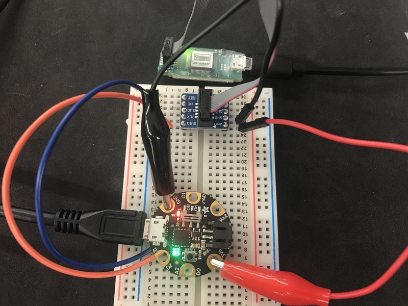
I found the appropriate guide.
wide shadow
 tulip sluice
Does anyone have a link to resources that can introduce me to coding the s3 feather TFT? I have code from an Arduino Nano that I want to port and use the screen, but I'm finding it really hard to get started...
manic jewel
tulip sluice
Does anyone have a link to resources that can introduce me to coding the s3 feat...
 tulip sluice
manic jewel
https://learn.adafruit.com/adafruit-esp32-s3-tft-feather
tulip sluice
manic jewel
https://learn.adafruit.com/adafruit-esp32-s3-tft-feather
That's good for setup, but I couldn't find any tutorials on how to program it. Like what libraries to include, function calls, etc.
manic jewel
tulip sluice
That's good for setup, but I couldn't find any tutorials on how to program it. L...
Try this - https://learn.adafruit.com/adafruit-1-14-240x135-color-tft-breakout/arduino-wiring-test . It's the same TFT.

Adafruit Learning System
Adafruit 1.14" 240x135 Color TFT Display + MicroSD Card Breakout - ST7789
@tulip sluice On that same page, you will find a menu to another example about using the GFX library and drawing bitmaps.
solemn cliff
the factory default code is linked from the factory reset page, it uses the display and stuff
https://github.com/adafruit/Adafruit_Learning_System_Guides/blob/main/Factory_Tests/Feather_ESP32S3_TFT_FactoryTest/Feather_ESP32S3_TFT_FactoryTest.ino
tulip sluice
Oh - THIS!! I never knew that was there. 🙂

 clear badge
Im trying to use the bluefruit nrf52 and I cant seem to get simple lines of code to function. I tried to just set a certain pin HIGH and also tried having the on board led flash but neither have worked. The code compiles in arduino with no issue and burns bootloader on to the chip, I can also see an LED switch from a slow blink to a fast blink during upload then back to slow blink, but nothing happens after, even after pressing reset.
north stream
Burning the bootloader should not be necessary, it presumably would come with one. However, the next step is using the bootloader to upload your sketch onto the board, which is a different process, and the one you need in order for your code to run.
 viral spade
i need help with running two servos with different inputs with a trinket pro 5v
cedar mountain
viral spade
i need help with running two servos with different inputs with a trinket pro 5v
You'll probably want to explain where you're stuck.
viral spade
#include <Servo.h>
Servo myservo; // create servo object to control a servo
// a maximum of eight servo objects can be created
int pos = 0; // variable to store the servo position
void setup()
{
myservo.attach(9); // attaches the servo on pin 9 on the Trinket to the servo object
}
void loop()
{
for(pos = 0; pos < 180; pos += 1) // goes from 0 degrees to 180 degrees
{ // in steps of 1 degree
myservo.write(pos); // tell servo to go to position in variable 'pos'
delay(15); // waits 15ms for the servo to reach the position
}
for(pos = 180; pos>=1; pos-=1) // goes from 180 degrees to 0 degrees
{
myservo.write(pos); // tell servo to go to position in variable 'pos'
delay(15); // waits 15ms for the servo to reach the position
}
}
i am trying to add another servo and two potentiometers with one pot for each servo
cedar mountain
Well, adding a second servo would just be declaring and attaching it to another pin, like:```Servo myservo2;
myservo2.attach(PIN);```
viral spade
oh sent an outdated code this is for single servo sweep but do you understand what i am trying to achieve?
cedar mountain
Sure. Your main loop would likely just be reading the analog value from the two pots, converting it to an angle, and sending it to each servo.
viral spade
yes exactly!
viral spade
#include <Servo.h>
Servo myservo; // create servo object to control a servo
int potpin = 0; // analog pin used to connect the potentiometer
int val; // variable to read the value from the analog pin
void setup() {
myservo.attach(9); // attaches the servo on pin 9 to the servo object
}
void loop() {
val = analogRead(potpin); // reads the value of the potentiometer (value between 0 and 1023)
val = map(val, 0, 1023, 0, 180); // scale it to use it with the servo (value between 0 and 180)
myservo.write(val); // sets the servo position according to the scaled value
delay(15); // waits for the servo to get there
}
viral spade
okay it didnt work and i might need to add an resistor too
#include <Adafruit_SoftServo.h>
#define SERVO1PIN 0 // Servo control line (orange) on Trinket Pin #0
#define SERVO2PIN 1 // Servo control line (orange) on Trinket Pin #1
int potpin = A0; // analog pin used to connect the potentiometer
int val;
Adafruit_SoftServo myServo1, myServo2;
void setup() {
myServo1.attach(SERVO1PIN); // attaches the servo on pin 9 to the servo object
myServo2.attach(SERVO2PIN);
}
void loop() {
val = analogRead(potpin); // reads the value of the potentiometer (value between 0 and 1023)
val = map(val, 0, 1023, 0, 180); // scale it to use it with the servo (value between 0 and 180)
myServo1.write(val); // sets the servo position according to the scaled value
delay(15); // waits for the servo to get there
}
 lilac linden
help! I've been trying to get a feather m0 BLE to power on some neopixels but have had 0 luck so far. I'm using the test script ```#include <Adafruit_NeoPixel.h>
#ifdef AVR
#include <avr/power.h> // Required for 16 MHz Adafruit Trinket
#endif
#define LED_PIN 3
#define LED_COUNT 10
Adafruit_NeoPixel strip(LED_COUNT, LED_PIN, NEO_GRB + NEO_KHZ800);
void setup() {
#if defined(AVR_ATtiny85) && (F_CPU == 16000000)
clock_prescale_set(clock_div_1);
#endif
strip.begin(); // INITIALIZE NeoPixel strip object (REQUIRED)
strip.show(); // Turn OFF all pixels ASAP
strip.setBrightness(50); // Set BRIGHTNESS to about 1/5 (max = 255)
}```
and just cannot get anything to light up. I confirmed the LED's were working with another controller
https://cdn.discordapp.com/attachments/173256178338496512/1047358509769039902/IMG_1659.jpg https://cdn.discordapp.com/attachments/173256178338496512/1047358508942770236/IMG_1663.jpg https://cdn.discordapp.com/attachments/173256178338496512/1047358509332824075/IMG_1662.jpg


The green wire is what I'm connecting to the LED's and some 74AHCT125 level shifters but nothing is working. I don't have any idea what could be going wrong here
north stream
Hard to tell where the wires are going in your pictures
 inland gorge
lilac linden
help! I've been trying to get a feather m0 BLE to power on some neopixels but ha...
inland gorge
lilac linden
help! I've been trying to get a feather m0 BLE to power on some neopixels but ha...
That code does not actually turn on any LEDs. Are you doing anything in loop() to set LEDs? e.g. strip.setPixelColor(0, strip.Color(255, 0, 255)); strip.show(); will set the first LED purple
lilac linden
inland gorge
That code does not actually turn on any LEDs. Are you doing anything in `loop()`...
Yeah the loop is supposed to show several patterns.
void loop() {
  // Fill along the length of the strip in various colors...
  colorWipe(strip.Color(255,   0,   0), 50); // Red
  colorWipe(strip.Color(  0, 255,   0), 50); // Green
  colorWipe(strip.Color(  0,   0, 255), 50); // Blue

  // Do a theater marquee effect in various colors...
  theaterChase(strip.Color(127, 127, 127), 50); // White, half brightness
  theaterChase(strip.Color(127,   0,   0), 50); // Red, half brightness
  theaterChase(strip.Color(  0,   0, 127), 50); // Blue, half brightness

  rainbow(10);             // Flowing rainbow cycle along the whole strip
  theaterChaseRainbow(50); // Rainbow-enhanced theaterChase variant
}```I don't think theres any issue with the code im more leaning towards a wiring issue but im still unsure what I did wrong there. I basically followed the raspberry pi guide when wiring the LED's
inland gorge
lilac linden
I don't think theres any issue with the code im more leaning towards a wiring is...
It's hard to see what your wiring is from those photos. Do you have a wiring diagram or schematic? Are you sure those LEDs are NeoPixel/WS2812? It looks like there's six wires coming off of it, which sounds more like a DotStar/APA102 strip
lilac linden
inland gorge
It's hard to see what your wiring is from those photos. Do you have a wiring dia...
The LED strip has 2 wires for pwr and 2 for gnd but they are neopixels I assure you. The wiring is just like this - only difference is im using the feather m0


the only two relevant pins in this setup is pin 5 and gnd, I need to run 6 neopixel strips off of this controller but I want to get one lit up before committing to this
inland gorge
yes your LED_PIN define needs to match how you've got it wired up
clear badge
does any one have experience using protomatter library or know another library I can use, im trying to use it with a 64x64 led matrix and cant get it to output anything on my display. my board is also the nrf52 feather
north stream
Can you output test patterns on your LED matrix?
clear badge
No, it seems to just be displaying random pixels/lines regardless of what I tell it to do
north stream
Ah, that's different from "can't get it to output anything"
 fair eagle
Hey, could I possibly get some help when it comes to the STM32F405 Feather. I'm struggling to get any communication between Arduino IDE and STM32CubeProgrammer. I also don't know what kind of firmware to put under the highlighted section of the second picture


I'm new to all of this, so it could be a simple mistake
If I could also skip over the STM32CubeProgrammer that would also be fine. I tried following everything on the learn page for microcontroller, and I'm trying to connect via usb
clear badge
north stream
Ah, that's different from "can't get it to output anything"
sorry, meant that nothing i did would create an output
tulip sluice
Has anyone had issues with their S2 Feather TFT disconnecting while the Arduino IDE is in the process of compiling / uploading code? I'm working with just the board, no connections on any pins. It was working fine, and then it went into a boot loop, so I reflashed with the feather-esp32-s2-factory-reset-and-bootloader as per the instructions, and now I get these disconnects. Everything is stable until it (appears) to finish compiling, and starting to upload.
pine bramble
In platformio there's more than one way to upload, iirc. Something openocd for example.
 nova spire
I had a quick question
I am using the esp 32 pico with the STEMMA QT wire to a 6 DOF IMU
I wanted to know how do I access the data from the STEMMA QT in my arduino code?
tulip sluice
Is the esp32-s2 Feather TFT a touch screen? The touchscreendemo example returns 0 for pressure always.
nova spire
 leaden walrus
most likely via `Wire`
leaden walrus
most likely via `Wire`
I am using this one in specific https://www.adafruit.com/product/5395?gclid=Cj0KCQiAvqGcBhCJARIsAFQ5ke47jpO4xTB52u7PdWXImnzhzY01uxmJeQlb4UgdwNikKPAHBlDEfcgaAiupEALw_wcB

This dev board is like when you're watching a super-hero movie and the protagonist shows up in a totally amazing costume in the third act and you're like 'OMG! That's the ...
nova spire
leaden walrus
most likely via `Wire`
Could you possibly direct me on how to do this?
nova spire

Behold, the ST ISM330DHCX: an industrial quality Accelerometer+Gyroscope 6-DOF IMUs (inertial measurement unit) from ST. This IMU sensor has 6 degrees of freedom - 3 degrees each of linear acceleration and angular velocity at varying rates within a respectable range. For the accelerometer: ±2/±4/...
If I wanted to use wire1 in the code above, what would I need to change?
leaden walrus
here's the main guide for that:
https://learn.adafruit.com/lsm6dsox-and-ism330dhc-6-dof-imu/arduino
and the library lives here:
https://github.com/adafruit/Adafruit_LSM6DS
to switch to using Wire1, change this line:
if (!ism330dhcx.begin_I2C()) {
!ism330dhcx.begin_I2C(Wire1)
nova spire
if (!ism330dhcx.begin_I2C(0x6A)) {
leaden walrus
if (!ism330dhcx.begin_I2C(LSM6DS_I2CADDR_DEFAULT, &Wire1)) {
try that
or with the 0x6A
if (!ism330dhcx.begin_I2C(0x6A, &Wire1)) {
should be equivalent
nova spire
Trying the first one righ tnow
leaden walrus
don't forget the & in front of Wire1
nova spire
First one failed to find it
trying the second one right now
First one did successfuly upload though
leaden walrus
might be good to try running this i2c scanner to see what addresses show up
https://learn.adafruit.com/scanning-i2c-addresses/arduino-using-testbed
ohhhh....i think i know why it might not be working. it's an esp32 thing.
nova spire
leaden walrus
might be good to try running this i2c scanner to see what addresses show up
<htt...
Give me one second on this
nova spire
leaden walrus
```cpp
  Wire1.setPins(SDA1, SCL1);
if (!ism330dhcx.begin_I2C(0x6A, &Wire1)) {...
Okay
Were, good, just got it
Thanks alot
I would have never got it in 1 million years
leaden walrus
cool! glad its working.
nova spire
I really appreciate it.
 rose moss
Accidentally plugged in my 24V power supply into my Arduino Mega powered Nixie Tube Clock instead of my 12V one... I smell burnt components, It still turns on but does not display properly.... Is my entire clock destroyed, or just my Arduino Mega board?
 north stream
rose moss
Accidentally plugged in my 24V power supply into my Arduino Mega powered Nixie T...
north stream
rose moss
Accidentally plugged in my 24V power supply into my Arduino Mega powered Nixie T...
There are three likely possibilities: the low voltage power supply, the AVR chip itself, and the high voltage level shifters. If it displays at all, the high voltage power supply is presumably fine. The low voltage supply is basically the regulator (linear or switching) and its capacitors. If it's not producing a clean output, the AVR chip won't work properly. The AVR chip is the bulk of the actual logic in the clock. The level shifters are what it uses to let the low voltage control signals from the AVR turn on digits and switch between tubes.
 frosty thistle
Hi all, does anyone know if the Adafruit_MCP23017 library works on an ESP32? I have a very basic setup and I keep getting an error on mcp.begin_I2C().
north stream
What error do you get?
frosty thistle
In the example its if (!mcp.begin_I2C) { Serial.println("error"); }
So I just get "error" 🙂
scanner found the device at 0x20
I swapped out for a diff IC
And still same issue
I got it...
north stream
Hmm, the begin_I2C() method doesn't do much other than instantiate an Adafruit_I2CDevice and call its begin() method https://github.com/adafruit/Adafruit-MCP23017-Arduino-Library/blob/bf7eddb2fe1a739b7d13f856090e2a27c5ad0568/src/Adafruit_MCP23XXX.cpp#L33
frosty thistle
Docs say that default address is 0x20 so I left the begin_I2C() as it was in the example, but If I used begin_I2C(0x20) it works.
north stream
Good catch. I don't see the default address being set in the code for some reason, so that makes sense.
frosty thistle
Thats how I found it. I was looking in the library source for any extra error reporting. Thanks for looking!
 acoustic lichen
hi guys! I'm new to adafruit and just purchased the adafruit air pump and valve, but I use the arduino uno board. Anyone knows the code for the air pump and valve? I have little experience with coding 😢
frosty thistle
wait, I was looking in the wrong spot, as I went back I found this in the header file:
#define MCP23XXX_ADDR 0x20 //!< Default I2C Address
north stream
acoustic lichen
hi guys! I'm new to adafruit and just purchased the adafruit air pump and valve,...
Not much to the code, most people just turn them on or off (although you can get fancy and attempt speed control with PWM). The Uno can't drive high power devices like that directly, as the product page states: "Works great with either a power transistor (basic on/off) or a motor driver chip such as the L293D, and with any boards from our CRICKIT series."
leaden walrus
@frosty thistle 0x20 should be used by default. so seems weird that.
mcp.begin_I2C();
did not work, but
mcp.begin_I2C(0x20);
did work.
they should be equivalent.
 hollow coral
anyone here actually a contributor to the arduino project? (meaning like, github etc)
was wondering if there was someone I could poke to get a PR on a lesser used repo approved
 gilded swift
hollow coral
was wondering if there was someone I could poke to get a PR on a lesser used rep...
gilded swift
hollow coral
was wondering if there was someone I could poke to get a PR on a lesser used rep...
I’m not, but perhaps I know someone who might be depending on the repo
hollow coral
GitHub
Fixes msproul#7 and makes code compatible with later avr-gcc versions.
Hex file compiled with avr-gcc 11.2.0 on FreeBSD.
has only been about a day and a half but it's not an active repo so I wasn't sure if anyone was actually paying any attention to it
gilded swift
An okay, yeah I’m not familiar with anyone working on that repo. Best bet is to request a review on it and see if it pings someone to take care of it
 trail swallow
The Adafruit Feather M4 has an Enable pin for the 3.3v regulator, and I can ground it to disable the regulator. Fair enough. But if I do so, it really does disable it outright, not just disconnect the pin. So now the MCU has no power. Am I expected to put 3.3v in? This page suggests not, which makes me confused why there's a "disable the board" pin: https://learn.adafruit.com/adafruit-feather-m4-express-atsamd51/power-management#alternative-power-options-3122391
The reason I'm looking into this is to try to find if my project's sudden and unpredictable crashes are due to power problems.
inland gorge
trail swallow
The Adafruit Feather M4 has an Enable pin for the 3.3v regulator, and I can grou...
I believe the EN pin is meant to give you the ability to add an ON/OFF switch to your project. Switch EN to Ground and your project is turned off; unswitch EN from Ground and your project powers up.
trail swallow
Aah, okay. Neat, thank you!
That's backed up by https://learn.adafruit.com/adafruit-feather/feather-specification#enable-input-2861843
It does not disable VBAT/VUSB, see above for a circuit that will let you do that. It is OK if you decide to have EN de-power USB/BAT as well, but not required.
Most of the Feathers have an Enable pin that will allow shutdown via logic level
 jaunty nest
somebody here knows what this part is on the back side of the Arduino Micro?

 heavy star
I think it might be a resistor
jaunty nest
here is another shot from a bit further away
 gilded swift
Looks like a PTC fuse
jaunty nest
i just wonder where i can find that on the schematics
if thats the correct one https://www.arduino.cc/en/uploads/Main/arduino-micro-schematic.pdf
gilded swift
jaunty nest
if thats the correct one https://www.arduino.cc/en/uploads/Main/arduino-micro-sc...
F1 by the usb connector
jaunty nest
but wouldn't a PTC fuse look like this part?
 gilded swift
Not necessarily
jaunty nest
you mean that i guess?
 gilded swift
Yeah
jaunty nest
many thanks
heavy star
I was about to say might be the PTC fuse too after poking around
heavy star
I wonder why it has an infinity symbol…
jaunty nest
arduino logo
jaunty nest
i thought it might be something special, custom made or so
jaunty nest
oh 
maybe thats why arduino logo contains it, and maybe thats why they want one having that symbol on it on their product 
jaunty nest
i thought they laser it on (or something) on their own ^^
again, many thanks. Trying to rebuild it in KiCAD with my bad knowledge 😂
 stray jay
I just switched my playground express from makecode/javascript to arduino, I was able to run the Blink example successfully, but when i tried to later modify the code to CircuitPlayground.setPixelColor, it's not working. is there something I'm missing, I pulled in the library but maybe i need to initialize it? i dunno
manic jewel
stray jay
I just switched my playground express from makecode/javascript to arduino, I was...
Did you get an error message?
Or post your code here
stray jay
no it uploads fine, but no lights
#include <Adafruit_Circuit_Playground.h>
void setup() {

  CircuitPlayground.setBrightness(50);
  pinMode(LED_BUILTIN, OUTPUT);
}

void loop() {
  CircuitPlayground.setPixelColor(5, 200, 0, 0);
  delay(5000);                      // wait for a second
  CircuitPlayground.clearPixels();
  delay(5000);                      // wait for a second
}```
GitHub
library for Circuit Playground board. Contribute to adafruit/Adafruit_CircuitPlayground development by creating an account on GitHub.
manic jewel
Lots of other examples in there as well.
@stray jay You might also consider using CircuitPython if you are new to programming.
stray jay
ok, i'll check it out. I moved away from the javascript/makecode solution because I need to do more advanced things with the microphone than it allows
hollow coral
is there a way for an Arduino connected to a PC via USB to identify the device it's connected to?
to be clear I want the Arduino to be able to identify the host, not the other way around
looking for a rudimentary way to make sure the device it's connected to is the device it's supposed to be connected to
cedar mountain
I'm not aware of a built-in USB mechanism to do that, so it would probably rely on some additional software on the PC side to send a unique identifier like its MAC address, or a cryptographic key if you want to be secure about it.
hollow coral
also, if you outgrow a mega is there something above it?
mostly need more program memory
more GPIO is a +
I'd look at an RPi but they are like impossible to find so building a project around one seems silly
especially since speed isn't really an issue
like I was looking at just splitting the code across multiple megas but that seems weird
the teensy looks plausible but it out of stock everywhere
wide shadow
Adafruit is starting to sell RP2040 based boards.,
stray jay
I'm trying to follow the code samples here: https://learn.adafruit.com/circuit-playground-sound-controlled-robot/using-the-microphone
But it does not compile, instead i get the following errors: ```C:\Users\nelso\Documents\Arduino\libraries\Adafruit_Circuit_Playground\utility/Adafruit_CPlay_Mic.cpp:293: undefined reference to fft_input' C:\Users\nelso\Documents\Arduino\libraries\Adafruit_Circuit_Playground\utility/Adafruit_CPlay_Mic.cpp:294: undefined reference to fft_execute'
C:\Users\nelso\Documents\Arduino\libraries\Adafruit_Circuit_Playground\utility/Adafruit_CPlay_Mic.cpp:295: undefined reference to `fft_output'
Can someone help me get back on track?I've been using chat.openai.com to help with fixing my errors. It is doing quite well.
north stream
hollow coral
mostly need more program memory
Maybe look at the Grand Central?
wide shadow
Is it really that much improved over the Mega? I know it is Adafruit's replacement for the Mega.
north stream
Mega: 16MHz, Grand Central: 120MHz. Mega: 8kB RAM, GC: 256kB RAM. Mega: 256kB flash, GC: 1MB flash.
Note that the Grand Central is a 3.3V board, while the Arduino Mega is a 5V board, which may or may not be an issue, depending on what you're connecting it to.
hollow coral
Oh I was actually looking at the SAMD51 line directly, didn't know there was a board for it
wide shadow
From what I've been reading SAMD51 boards are becoming more scarce.
hollow coral
Yeah. I wrote it off because I couldn't find it in stock
wide shadow
Some of the other vendors that were using SAMD51 boards are now replacing them with RP2040 based boards.
hollow coral
If not for the shortages I'd probably just say screw it and go CM4
Yeah. The 2040 is easy to find
But it doesn't have as many GPIO
And every pin on the mega is used
So would have to deal with io expanders then
gilded swift
Other people are using nRF52 and nrf53 because they are in stock
wide shadow
I just checked, and the Grand Central M4 is currently in stock.

Are you ready? Really ready? Cause here comes the Adafruit Grand Central featuring the Microchip ATSAMD51. This dev board is so big, it's not named after a Metro train, it's a whole ...
hollow coral
Yeah but the chips aren't. So to develop something with that board and then try to make it wouldn't work
wide shadow
Are there good proto boards for them?
gilded swift
Between both in stock, like 240k nrf52840
Adafruit have nRF52840 feathers
Not sure how many pins you need though
gilded swift
The feathers no
hollow coral
I wish they made a version of the mega with more program memory
wide shadow
Almost sounds like you might need to daisy a few MCUs together.
hollow coral
Because it's really only program memory that's the issue
wide shadow
If that is the case, couldn't you make something like this work?: https://www.adafruit.com/product/4719

FRAM, or Ferroelectric Ram, is the coolest new data storage method that all the fashion magazines are talking about. Oh wait, no that's quilted handbags. But FRAM is pretty damn cool ...
hollow coral
No
gilded swift
47 on the nRF52840 73VQFN
hollow coral
Program memory as in flash
brazen falcon
Well, RP2040 can go up to at least 16MB
gilded swift
So 7 short
hollow coral
Yeah but not enough GPIO
gilded swift
What are you making that is using all 54 GPIO on the mega 54
hollow coral
And it's timing sensitive so I'm not sure how well io expanders would work
brazen falcon
GPIO expanders work?
hollow coral
Like sensitive enough to use nop instead of delay lol
wide shadow
Is there anything you could shave off to the same GPIO expander and keep good enough timing?
brazen falcon
ESP32-S2 has up to 43, but I think 6 of those are dedicated.
hollow coral
I was checking into that but I'm not seeing anything
gilded swift
Why not use an FPGA if timing is a concern?
hollow coral
Expense
gilded swift
Tons of FPGA have 100+ GPIO
hollow coral
And shortages lol
wide shadow
Kind goes towards my thoughts on daisying a few MCUs with different branches of GPIO for expansion
gilded swift
Plenty that are <$100
hollow coral
That are easy to write for?
wide shadow
That's subjective.
hollow coral
 gilded swift
Verilog is pretty straight forward by the estimation of a lot of people who’ve learned it
Plenty of lattice chips can use ice studio
wide shadow
Maybe pump your code through chat.openai.com to see if it can optimize it in any way?
hollow coral
The code is already written so yeah. Would need to port it
gilded swift
Just put a risc-v soft core lol
wide shadow
I was thinking of RISC-V as well.
hollow coral
I've never messed with fpga. Only Arduino really
wide shadow
There are some good web based MCU emulators out there.
gilded swift
Yeah
wide shadow
That could help you get acquainted with the chip before you get the hardware.
brazen falcon
Are there usable risc-v cores for fpga now without proprietary extra stuff you need to add?
cedar mountain
Yes, there are open-source cores available I believe.
brazen falcon
I haven't been following it too closely but last time I looked (a while ago) there wasn't anything functional.
That was 6 months or a year ago though
cedar mountain
I don't know your project details, but if you've been happy with a Mega, you probably would want to target a larger-package ARM chip like a 100-pin STM32 instead of switching completely to a FPGA plus soft-core architecture.
brazen falcon
STM32 gets into availability again though
wide shadow
How large of production runs of the product can also make a difference.
cedar mountain
I mean, just filter on Digi-Key for "Cortex M", ">80 pins", and "in stock", and see what pops up. 😉
brazen falcon
Air105 is an M4 design with a QFN88 package and might have enough GPIO though I haven't looked into how many of those are dedicated.
gilded swift
And there’s 51 in stock
brazen falcon
Any STM32 >QFP64 seems to be super dicey to find.
hollow coral
The ice stick looks interesting
But the board only has 16 IO despite the chip having 144?
Did they really use all of them or did they just not break them out to save space?
cedar mountain
The latter, I'd assume. They just wanted a small form factor.
Did they really use a 144-pin package on that, though? There are a number of iCE40 chip variants.
hollow coral
I thought so
I mean I can use 16 to proof of concept it but I'd immediately outgrow it as soon as that phase was over
 hollow coral
cedar mountain
Did they really use a 144-pin package on that, though? There are a number of iCE...
hollow coral
cedar mountain
Did they really use a 144-pin package on that, though? There are a number of iCE...
TQ144
hollow coral
The alchitry cu looks like it exposes most of the pins
 dusk orchid
Hey, this library is not updated in the registry, can someone take a look please https://github.com/adafruit/Adafruit_LvGL_Glue/issues/15#issuecomment-1337411808
--EDIT-- Duped to git channel

GitHub
Compile Error details; .pio/libdeps/nodemcuv2/Adafruit LittlevGL Glue Library/Adafruit_LvGL_Glue.h:46:3: error: 'lv_disp_buf_t' does not name a type; did you mean 'lv_disp_d...
 leaden dew
where's the best place I can find info or a guide on PID controller?
leaden walrus
that's a very broad and complex topic. there won't be any one single "best" option.
can you clarify what you are after. trying to understand PID in general? working with a specific PID controller?
leaden dew
so eventual goal is working on a spider-like walking robot. So to start and get used to arduino and servos etc, I'm making a robot arm to explore coding the motion of the motors
I'm not sure a whole lot about PID, but what I know is that P, I, and D are different bits that work together to produce smoother motion
so i guess what I'm after is a teaching like video that I can plop next to me while I sit and work with their code n stuff. Oh, and for the moment I want to pre-code a routine (just cause I think it's easier to learn PID that way)
leaden walrus
have you selected motors yet?
leaden dew
yep, SG90 micro servo motors; yes small and 'weak' but tis a learning curve 🙂
and so far, they've been pretty good at holding positions under load; depending what random code I found and tested them with
leaden walrus
those are hobby servos
in general, you don't need to worry about PID control when using those
it's buried in the servo and you don't have any access to it
leaden dew
ahh; is that the little encoder thing right next to the dc motor?
not the 'PID controller' as per say, but the thing that has the PID controller code
leaden walrus
probably. a part of it - the feedback. which is typically a pot (variable resistor).
the actual PID control may be implemented via a dedicate circuit or some IC
have you broken one of the SG90s open to see the guts?
leaden dew
leaden walrus
in general, you don't need to worry about PID control when using those
is there any particular reason like it's precoded and accessed differently in the smaller ones, or just PID is meant for another application?
leaden dew
leaden walrus
have you broken one of the SG90s open to see the guts?
yep, one of the plastic ones I decided to overcharge; wondered how functionality and it's torque varied with voltage
leaden walrus
it's so they are easy to use
all you need to do is feed them a PWM signal and the servo does the rest
the PWM signal is like a "commanded position"
leaden dew
ohh, so if I vary that command with respect to something else (I'm guessing time?) then it should produce a curve
if the start and end position and path were plotted on a graph
leaden walrus
in general, yes. with hobby servos, there's no speed control. when you change the PWM signal, they respond by moving to the new location as fast as possible
so if you wanted to have some kind of controlled motion, you'd end up sending a series of "raw" PWM signals
like if you wanted to move "slowly" from A to B
you wouldn't just send it the PWM signal for B
you'd need to send a constantly updating signal that slowly varies from A to B
(this is hobby servo specific)
leaden dew
Is there something to explain why when it rotates sometimes and holds a position, there's a really good amount of forceback, and other times I can push it out of it's position
would the current available affect it in these servos?
or is that a variable or setting I can call from the Servo.h file?
leaden walrus
it should try to maintain position as long as the PWM signal is being sent
if the PWM signal is flat, then most servos will "deactivate" - that's when you could grab it and move it by hand
leaden dew
So what kind of servo would best be utilised for PID? Dw, still going to do my robot arm stuff, just curious what type of motor uses it
leaden walrus
first see if the hobby servos will work
if you need to implement your own PID controller, that's like 10000000x more complex
what's currently not working when trying to use the hobby servos?
leaden dew
everything's all good atm, not got any expectations, like curious george with an arduino board and motors rn (I'd love to see that animated)
just curious, not sure what the 'keywords' around motors are what to search for things: because I believe that if I can think of a simpler variation of what I want, someone's probably done it on the internet
native dagger
Typically you wouldn't use PID with servos since they have their own feedback system built in, that's their strength. But many other motor types benefit
leaden dew
i also realise this may be the wrong channel to talk servos, just seen the robotics channel
leaden walrus
oh yah. good idea. yep, if you want to get more nuts-n-bolts on PID, that'd be a good channel to chat about it.
 sacred ivy
I need to make a variable available across different c files in a given complier, but I dont know how my IDE would reference it. What would it be called or how could I do it?
More info:
So I have main.c and I have tmr1.c. I want to make a variable in main.c but also use it in tmr1.c
sacred ivy
AHH I found it. "extern" is the keyword
brazen falcon
There's a technique called servo easing to remove the sudden jerk at the end of a servo motion.
If you don't require a full PID solution it would be lighter weight.
 grave mortar
Hi friends I'm too dumb I want to build a hex code by joining certain sections of it together, obviously this gives me the hex as a sting but how do I convert it to 0xC800F641F
basehex = "0xC800F" toggelone = "E4" toggletwo = "64" up = "1F" code = basehex + toggeltwo + up;
 lilac ginkgo
Any reason to use strings? You could use hex literals ```c
basehex = 0xC800F;
toggelone = 0xE4;
toggletwo = 0x64;
up = 0x1F;
code = basehex + toggeltwo + up;
If you need their bytes to be concat'ed, add trailing zeroes for alignment (and OR should be faster at that point), formatted the text so you can see the alignment  ```c
basehex   = 0xC800F000000; //or 0xC800F << 24
toggelone =      0xE40000; //or 0xE4 << 16
toggletwo =        0x6400; //or 0xEA << 8
up        =          0x1F;
code = basehex | toggeltwo | up;
No reason I've never worked with hex, basically there's a toggle bit in the original binary that I'm trying to match up with so don't know what I'm fdoing 😛
grave mortar
I'll tey this when I pull it out tomorrow thank you
 hearty gazelle
I'm writing a program that involves a loadcell that I want to calibrate in the beginning. I use input from the serial monitor to start the different stages of the calibration. Here is the code that does so, mostly taken from the HX711_ADC library. I'm using a state machine in loop(), so that I can easily run multiple functions in parallel. I converted this into a state machine as well, replacing the while loops with if statements and incrementing the calibration state instead of setting _resume to true. I found that I was losing inputs from the serial monitor this way. Is there an ideal way to work around this? I've looked at buffering here, http://www.gammon.com.au/serial, but I feel like there should be a simpler way of dealing with this.
boolean _resume = false;
  while (_resume == false) {
    LoadCell.update();
    if (Serial.available() > 0) {
      if (Serial.available() > 0) {
        char inByte = Serial.read();
        if (inByte == 't') LoadCell.tareNoDelay();
      }
    }
    if (LoadCell.getTareStatus() == true) {
      Serial.println("Tare complete");
      _resume = true;
    }
  }

  Serial.println("Place known mass on loadcell. Enter into Serial Monitor.");

  float known_mass = 0;
  _resume = false;
  while (_resume == false) {
    LoadCell.update();
    if (Serial.available() > 0) {
      known_mass = Serial.parseFloat();
      if (known_mass != 0) {
        Serial.print("Known mass is: ");
        Serial.println(known_mass);
        _resume = true;
      }
    }
  }
Just incase, here is my loop (The code above is called in ManageLoadCell()):
void loop() {
  if (systemState == 0) { //Standby
    TimeKeeper();
    WriteDataToSD();
    WaitForInput('s');
  }
  else if (systemState == 1) { //Initialize load cell
    TimeKeeper();
    WriteDataToSD();

    ManageLoadCell();
  }
  else if (systemState == 2) { //Countdown
    TimeKeeper();
    WriteDataToSD();

    GetCellData();
  }
  else if (systemState == 3) { //Ignite motor
    TimeKeeper();

    //Log data
    //Switch when load cell input changes
    systemState++;
  }
  else if (systemState == 4) { //Motor is running
    TimeKeeper();

    //Log data
    //Wait for a few seconds after no load cell input before moving on to next stage
    systemState++;
  }
  else if (systemState == 5) { //Motor no longer running
    TimeKeeper();

    systemState = 0;
    //Probably want to do some sort of shut down procedure
    //systemState++;
  }
  else if(systemState == 42) { // Abort
    TimeKeeper();
  }
}
I'm now using a while loop in the main state machine to accurately read serial input, with a state machine instead of while loops in ManageLoadCell(). I'd still love to know if there are any easier ways of accurately reading serial input in the loop without while loops and preferably without buffering.
 lilac ginkgo
hearty gazelle
I'm now using a while loop in the main state machine to accurately read serial i...
lilac ginkgo
hearty gazelle
I'm now using a while loop in the main state machine to accurately read serial i...
no idea about the issue itself, but you can probably clean this a bit to make it easier to read when someone tries to help:
- use
switchoverif/elses - since
TimeKeeper()is called on each state, get that done right before theswitchinstead of duplicating it for every branch - im pretty sure that
while (systemState == 1)would be equivalent to the your current code with an extraif (systemState == 1)before the loop
 sudden dome
Does anyone know if it's possible to load a binary at runtime and run it on ESP32 without reflashing firmware? So for example you would have a firmware running on the ESP that can select and load another binary from an SD card or from flash memory. I can't find the right documentation or examples to get started.
hearty gazelle
lilac ginkgo
no idea about the issue itself, but you can probably clean this a bit to make it...
Would the if statement before everything change anything?
I don’t see how it would have an effect
But I’ll try just in case
Thanks for the help
lilac ginkgo
hearty gazelle
Would the if statement before everything change anything?
i dont understand the question, but afaik: if (condition) { while (condition) {//code} } should be equivalent to while (condition) {//code}
also, instead of getting your code indented a lot by chaining ifs you could add guard clauses, which helps with readability ```c
if (!condition)
return; //for example
while (condition) {
//code
}```
hearty gazelle
lilac ginkgo
i dont understand the question, but afaik: `if (condition) { while (condition) {...
Ah, I get you. I want to keep the if statements somewhat similar and coherent. I found that when I don’t use the while loop, I lose some input from the Serial Monitor (that I enter in). I’m mainly trying to find a way to get accurate input without using while loops.
 stone spade
Hey there. Does anyone know of a conflict between the Adafruit Arduino neopixel library and MQTT libraries? I have tried both pubsubclient.h and MQTT.h, and with both I get board crashes right as the neopixel strip.begin() command is called. The board continually reboots. I have swapped in FastLED and it works fine, but I want to control an RGBW strip and FastLED Does not support these. Any thoughts or workaround suggestions are appreciated!
I should mention to that the board in question is an ESP 32 C3
And also that stripping out the MQTT code and the neOpixel library works fine.
livid osprey
stone spade
Hey there. Does anyone know of a conflict between the Adafruit Arduino neopixel ...
Is there an error message, or does your program unexpectedly restart?
In the case of the former, the exact message really helps nail down the exception occurring.
If the lattter is true, what might be happening is alignment of spikes common to both initiation of pixels and Wi-Fi radio causing your voltage to drop below operating voltage.
stone spade
Watching the serial monitor, My board successfully connects to Wi-Fi in the setup of the sketch and then reboots right after as the neopixel.begin() hits. This is the error it shows:
ESP-ROM:esp32c3-api1-20210207Build:Feb 7 2021rst:0x3 (RTC_SW_SYS_RST),boot:0xd (SPI_FAST_FLASH_BOOT)Saved PC:0x403821bcSPIWP:0xeemode:DIO, clock div:1load:0x3fcd6100,len:0x438load:0x403ce000,len:0x918load:0x403d0000,len:0x24e4entry 0x403ce000
I don’t know if this makes any sense to you but, googling this didn’t provide much Insight for me.
wide shadow
grave mortar
Hi friends I'm too dumb I want to build a hex code by joining certain sections o...
If you want to convert from an integer type to a hex string, you could do: String(integer_value, HEX) and you will get a hex string as a result.
grave mortar
wide shadow
If you want to convert from an integer type to a hex string, you could do: Strin...
I'm trying to construct the hex using strings but I don't think I need to given the previous answer
wide shadow
Apparently there is now a RISC-V processor ESP32C3 out now on Seeed Studio, XIAO ESP32C3 $5/ea
north stream
hearty gazelle
Ah, I get you. I want to keep the if statements somewhat similar and coherent. I...
I usually do this with two state machines, so the loop() gets called repeatedly, and within it, it does a check for an incoming character and checks for other stuff it might need to do. In the code for an incoming character, it appends the character to a buffer and determines if a complete command has been received, if so, it executes it.
hearty gazelle
north stream
I usually do this with two state machines, so the loop() gets called repeatedly,...
So do you check for each type of command in the buffer with a switch?
north stream
hearty gazelle
So do you check for each type of command in the buffer with a switch?
That depends on how your commands are structured. Sometimes a switch statement is the way to go.
sacred ivy
Is doing something like this:
UART1_Write(0xFF); UART1_Write(0xFF); UART1_Write(0xFF);
Considered bad practice? Would it make more sense to make a for loop with only 3 iterations?
pine bramble
One way to look at it is that doing it that way forces 'them' to check each line for differences, when looking at your code, months from now.
In a loop that's explicit.
Both versions are likely to compile to an identical binary image. The compiler often optimizes such things.
sacred ivy
makes sense as this is easier to read months/years from now. "Oh, this makes sense and its readable" vs "Why did I use a for loop?"
pine bramble
I like to see both delimiters '{' and the matching '}' at all times, so that usually means I compress vertically to the extent that 'indent' reformats my code. (Similar to Control+T in Arduino IDE.)
The text editor I work with matches them and highlights both at the same instant. ;)
Since the keybinding to make a duplicate of one line of code, in rvim, is 'yyp' it's very easy to replicate one line exactly. I'll do this when I'm in a hurry to prove an idea.
 bitter veldt
hello. i would like to power a Qt Py via external 5V source. i am reading https://learn.adafruit.com/adafruit-qt-py-esp32-s3/pinouts and it says:
You can also use the 5V pin as a voltage input but you must have some sort of diode (schottky, signal, power, really anything) between your external power source and this pin with anode to battery, cathode to 5V pin.
but i am not quite able to grok what it means. the diode would be inline +5V from PSU to 5V pin and then PSU GND goes to the BAT or the GND pin?
hearty gazelle
Just a quick question, is the reason Serial input (from the serial monitor) is sometimes lost because the arduino is running other code/processes when the input comes in?
north stream
It can be. There are various possibilities.
 frosty prairie
anyone have some reading/watching material on making smart messages?
I'm sending some small data over CANbus, however I think just sending 1-9 is a bit of a waste
like I could have some error detection in there or something else?
sacred ivy
Am I using atoi correctly?
char testbuf[3]={1,2,3}; unsigned int val; val = atoi(testbuf);
(testbuf is literally a buffer to make sure the function can handle arrays)
 tardy iron
sacred ivy
Am I using atoi correctly?
`char testbuf[3]={1,2,3};
unsigned int val;
val = at...
tardy iron
sacred ivy
Am I using atoi correctly?
`char testbuf[3]={1,2,3};
unsigned int val;
val = at...
no. that array of numbers isn't a null-terminated C string, which is what atoi() needs
sacred ivy
ahh let me change that, I see an error already
sacred ivy
tardy iron
no. that array of numbers isn't a null-terminated C string, which is what `atoi(...
char testbuf[3]={"123"};
Im assuming is correct
tardy iron
sacred ivy
char testbuf[3]={"123"};
Im assuming is correct
you could try char testbuf[] = "123", which will create a null-terminated string with the digits 1, 2, 3.
sacred ivy
My problem is....my data Im getting is in an array. So [0] is "1", [1] is "2", [3] is "3"
Its not "123"
🤔
tardy iron
what exact form does your input have?
sacred ivy
Im gonna get back to you on that in ~an hour if thats ok.
But its basically a string buffer from a nextion display and I am sending it as such:
"n1_"1" "2" "3" (spaces are only there for readability here on discord)
tardy iron
someone else will probably be here, even if i'm not
sacred ivy
I actually figured it out. Im not getting strings back, but rather ASCII characters that represent those numbers. So, "1" is actually 49 (base 10) per the ASCII code. I got my thinking mixed up and thought I was getting a string, but in reality, Im just getting the representation of each number. My USART buffer is a char variable and not a string.
And actually..I did this before 😅 but on another programming language. Basically, all I have to do is subtract 48, then multiply by either 100, 10 or 1 for the respective place, and then add it all together.
At least in theory
tardy iron
or it might be easier to copy the right number of characters from your USART buffer into a char array and null-terminate it, then pass it to atoi
sacred ivy
tardy iron
or it might be easier to copy the right number of characters from your USART buf...
😅 so this worked.
Basically instead of doing this:
char IntBuffer[4];
All I needed to do was add a "\0"
char IntBuffer[4] = "\0";
tardy iron
sacred ivy
😅 so this worked.
Basically instead of doing this:
`char IntBuffer[4];`
All I...
huh, that looks like it would work, but maybe not for exactly the reason you expect 😁
sacred ivy

Stack Overflow
How do I convert a character to a string in C. I'm currently using c = fgetc(fp) which returns a character. But I need a string to be used in strcpy
1st answer basically lol.
hold up now I have to try something 🤔
tardy iron
it's close… you're initializing a 4-element char array with {0, 0}, basically, and C zero-initializes all trailing array elements that aren't specified in the initializer, so the other two chars in the array are also zero
sacred ivy
OH, so thats why it works. Initially its all set to 0, but In reality, Im only reading 3 bytes, so the last byte stays.
Im not really reading 4 bytes
tardy iron
ah, that makes sense
sacred ivy
ahh but heres the kicker: it works without it now too. My buffer has that null char automatically 🤔 . I think I did something last night to make things work. What probably made it work was doing this:
IntBuffer[0]=buf[3]; IntBuffer[1]=buf[4]; IntBuffer[2]=buf[5];
Is it nice looking? No. Do I really need a for loop for this? Probably not. Its easy to read (like I posted way above). This function got rid of the "\0" null characters by just moving stuff in a new buffer. I think also, "buf" then had leading 0's, causing the atoi function not to work. By getting rid of those, makes it work 😅
ahhh what sleep will do
tardy iron
sacred ivy
ahh but heres the kicker: it works without it now too. My buffer has that null c...
does it, though? char IntBuffer[4] isn't guaranteed zero-initialized if it's declared inside a function. (it is zero-initialized if it's outside of a function; one of the annoying gotchas of C)
sacred ivy
Its declared at the beginning before main BUT thats a good point. Just in case something gets stuck, I'll memeset it to 0 before and after use
you know, a random char might get stuck and then the whole thing wont work lol
 pine bramble
Stupid question, but if I use a Stemma QT sensor and a Stemma QT display, would I be able to run the display through the sensor, while still reading from the sensor? (the last time I did anything with arduino was 5th grade lol)
cedar mountain
Yes, the connection is an I2C shared bus, so you can hook up a number of Stemma boards to the same wires in any topology and access all of them, assuming they have non-conflicting addresses.
pine bramble
Thanks!
 mighty maple
how can i output to the serial port of an arduino nano without using the arduino libraries? im trying to learn bare metal programming to actually understand whats happening behind the hood.
cedar mountain
mighty maple
how can i output to the serial port of an arduino nano without using the arduino...
You'd want to access the AVR's UART peripheral registers directly. Time to dive into the datasheet!
mighty maple
yeah, i saw a tutorial on that but it doesnt seem to work:
#include <avr/io.h>

#include "uart.h"

void UART_init(uint16_t ubrr) {
    // set baudrate in UBRR
    UBRR0L = (uint8_t)(ubrr & 0xFF);
    UBRR0H = (uint8_t)(ubrr >> 8);

    // enable the transmitter and receiver
    UCSR0B |= (1 << RXEN0) | (1 << TXEN0);
}

void UART_putc(unsigned char data) {
    // wait for transmit buffer to be empty
    while(!(UCSR0A & (1 >> UDRE0)));

    // load data into transmit register
    UDR0 = data;
}
I'm unfamiliar with the AVR off the top of my head. Do you need any further initialization to set the GPIO pins you're using to UART mode or something like that?
cedar mountain
If you have a logic analyzer, seeing if the pins are outputting anything would be a great troubleshooting step. It's easy to get the baud rate wrong sometimes, and that'll be obvious if it's otherwise working.
tardy iron
@mighty maple how are you compiling your code?
mighty maple
ah i may need to set the frame format
 mighty maple
tardy iron
<@746959257030623281> how are you compiling your code?
mighty maple
tardy iron
<@746959257030623281> how are you compiling your code?
i made a really terrible makefile which may also be the issue
SRC=$(wildcard *.c)

default: $(SRC)
    avr-gcc -Os -DF_CPU=16000000UL -mmcu=atmega328p -o ./bin/m328.bin ./src/*.c
    avr-objcopy -O ihex -R .eeprom bin/m328.bin bin/m328.hex
    sudo avrdude -F -V -c arduino -p ATMEGA328P -P /dev/ttyUSB0 -b 115200 -U flash:w:bin/m328.hex
its some sort of frankenstein made up of youtube tutorials and stack overflow tabs
mighty maple
YES

now interfacing with a serial eeprom
rn my goal is to write a wozmon type thing
sacred ivy
@mighty maple I know im a bit late, but another option is to use mplabx, with XC8 and then download code configurator v5. From there you can generate the code for UART and see what it looks like, or just use it as it gives it.
Its also worth poking around here:
https://microchipdeveloper.com/8avr:usart-mega-configuration
north stream
You can also look at the source code to Arduino (yay open source) and see how they do it.
sacred ivy
Ive done that when trying to port over code from Arduino libs to my own complier. Problem is, they tend to use tricks and pointers and stuff I sort of cant read 😅
north stream
True, it can take some effort to prise out what the code is actually doing. I've been known to do a fair amount of copy, paste, and modify, to move from their code to my code.
stray jay
Can anyone help me get started with audio input pattern recognition using the ZeroFFT library? I'm using the circuit playground express
pine bramble
I need help connecting and uploading to an esp8266 12-e. If anyone wants to help, please ping me.
 cold lagoon
Hi. yesterday i wrote a 200 line code and today i discovered that it doesn't work, so i broke it down to the basics, which also don't work.
any ideas why?

the commented stuff is the rest of the code. but i don't even get the transmission to work so its unimportant
pine bramble
Breaking it down was a good idea. Posting images may not be (did not look ;)
cold lagoon
normally i post code as code but when you have a send and a receive part its easier to compare side by side
pine bramble
That makes sense. ;) I really wouldn't look in the first place to see what you did, there ordinarily. ;)
I would hard-code the analogWrite() line as the entire program, with whatever is required for it to 'work' as my first test.
You probably want early feedback to know that the code is doing what it is supposed to be doing.
If I write a complex program, and manage to get it working 'once' I use the current wiring of the hardware as a test bed, and (sometimes) start over, using the newly-tested hardware to validate the code as it gets rewritten.
That way I know (for sure) the hardware is 'good' and can concentrate on writing good code that has (lots fewer) compromises in it (initially present to 'just get it to work, once') ;)
cold lagoon
I've tried everything. Rewiring everything checking the pull-up resistors, writing a even simpler code. but it still doesn't work. here is the new code:
 stable forge
cold lagoon
I've tried everything. Rewiring everything checking the pull-up resistors, writi...
stable forge
cold lagoon
I've tried everything. Rewiring everything checking the pull-up resistors, writi...
The boards have a common ground, right? I am not familiar with Arduino I2C controller/target code, though looking at https://create.arduino.cc/projecthub/PIYUSH_K_SINGH/master-slave-i2c-connection-f1aa53, it looks ok. Do you have a scope or logic analyzer to look at what's on the bus?
cold lagoon
they have vommon ground. sadly i dont have anythign to watch whats on the bus
inland gorge
cold lagoon
I've tried everything. Rewiring everything checking the pull-up resistors, writi...
For your I2C peripheral, why are you using USIWire instead of normal Wire? What are the two boards being used? Are they both running at the same voltage? (3.3V or 5V)
cold lagoon
its an arduino nano and an Attiny 44
tha attiny 44 runns with 3.3V
but it has worked before with a nother sketch (that i sadly dont have anymore)
leaden walrus
can you get the attiny address to show up in an i2c scan?
cold lagoon
.......
you can officially call me the dumbest person alive. the i2c lines where plugged in to D4 and D5 instead of A4 and A5. AND I WASTED A WHOLE DAY ON IT
sorry for wasting your time 🙂
pine bramble
Hey what'd be not very smart would be to not retain the lesson in any way at all. ;)
The lost time is your motivation to not repeat the mistake (not that it's a guarantee, but the motivation can be quite substantial).
check your assumptions - that's rather inexpensive to do, so do it.
inland gorge
cold lagoon
sorry for wasting your time 🙂
hey but you got it working! glad it was a simple issue! and we've all been there 🫠
 wraith current
wow, thanks a lot default I2C begin method. you made the optional frequency 0 so if you leave off the frequency then your I2c won't work at all. Just spent like 3 hours banging my head against this thing.
 north stream
Yow, that's a bad default
 cerulean knoll
does 0 default to 100khz deeper under the hood?
wraith current
@north stream thanks for the validation
 fervent roost
anyone know how set boundaries/margins with the gfx's print method? I'm trying to print some text on a screen but the text reaches the right most edge before it wraps, I would like it to wrap before it reaches the end
 deep tendon
Do you guys happen to know of any instances when trying to display a gif from AnimatedGIF library on a mini TFT screen where it doesn't display unless connected to a serial monitor? It's so weird like when I turn on the RP2040 without being connect to my comp it doesn't boot up. But when connected and outputting to the serial monitor it does. Wut??
north stream
Some code waits for the serial port to be ready before starting: code like this will hang forever if the port isn't connected. I've been bitten by this more than once.
pine bramble
Most of my projects blink an onboard LED or RGB until I start a telecomm program like hyperterm or putty and connect to it. ;) That way I can plug it into USB and see it's doing something predictable, without starting the terminal.
 quartz furnace
Hello everyone….. I’ve been tinkering around with audio on an ESP32-S3….. I know about I2S breakouts … what I’d like to also experiment with is a breakout like this one ?
Hey, have you heard the good news? With Adafruit STEMMA boards you can easily and safely plug sensors and devices together, like this Adafruit STEMMA Speaker - Plug and Play Audio Amplifier. ...
I take it that’s more for a board with a DAC pin? And while the ESP32 has a DAC , it’s no longer on boards like the ESP32 S3
Of note: the quality of the audio is not very important (I don’t think) I just want to play mp3 of Audio voice recordings, small maybe 5 seconds
quartz furnace
More about the project… create a MP3, use a File to hexadecimal conversion tool. Have that HEX Within the sketch …. Have some pin assignment to connect the above STEMMA Speaker into … possible?
quartz furnace
Found this but does not compile for ESP32 S3 https://github.com/damellis/PCM/blob/master/examples/playback/playback.pde

GitHub
Arduino library for simple playback of audio samples using pulse-code modulation. - PCM/playback.pde at master · damellis/PCM
 warped junco
For their synthesizer senior design project, one of my teams at Georgia Tech created a custom library to increase the PWM rate on the Adafruit Grand Central M4 Express from its default 1.8 kHz rate: https://github.com/mtfarren/synth-control

GitHub
Software for the MIDI-Controlled Hybrid Synthesizer project. - GitHub - mtfarren/synth-control: Software for the MIDI-Controlled Hybrid Synthesizer project.
 edgy ibex
How much ram does the ESP 8266 feather have? Specs say 4MB of Flash, but no mention of ram. In particular does it have enough to run a strand of 250 neopixels using the Adafruit_Neopixel arduino driver?
north stream
edgy ibex
How much ram does the ESP 8266 feather have? Specs say 4MB of Flash, but no men...
The old Feather Huzzah? Not a huge amount, maybe 45kB? Depending on your code and which other libraries you're using, it might have enough RAM to operate them. Note that you'll need about a 15 amp supply and some beefed-up power wiring to run 250 NeoPixels at full brightness.
heavy star
I did a Google for the ESP8266 in general and saw several say 16KB, but a couple said 48KB and 64KB
pine bramble
;) Not sure how you'll resolve this one. ;)
heavy star
I dunno how to code it, but I guess you could write something that allocates RAM in chunks and ramps up, printing the size/RAM usage to the console, see where it stops?
pine bramble
81920 bytes here:
https://github.com/esp8266/esp8266-wiki/wiki/Memory-Map
3ffe8000 14000 + . 3FFFC000  ok
14000 decimal . 81920  ok
80KB? weird
north stream
There are some debug utilities that can report free RAM available. How much RAM the pixels take depends on how they're used, and if there's other stuff going on (WiFi, for instance), that will eat up a bunch of RAM as well.
heavy star
Might want a co-processor
pine bramble
heavy star
80KB? weird
It's likely to combine two or three numbers that make more sense (even powers of two).
heavy star
Maybe 64 and 16
pine bramble
Gforth comes with ABSOLUTELY NO WARRANTY; for details type `license'
Type `bye' to exit
1 2* . 2  ok
1 2* 2* 2* 2* 2* 2* . 64  ok
1 2* 2* 2*   2* 2* 2* 2*   2* 2* 2* 2*   2* 2* 2* 2*   2*     . 65536  ok
1 2* 2* 2*   2* 2* 2* 2*   2* 2* 2* 2*   2* 2* 2*             . 16384  ok
1 2* 2* 2*   2* 2* 2* 2*   2* 2* 2* 2*   2* 2* 2*  ok
1 2* 2* 2*   2* 2* 2* 2*   2* 2* 2* 2*   2* 2* 2* 2*   2*  +  . 81920  ok
I used to do them in a regular calculator. ;)
north stream
I still use the Unix bc tool for stuff like that
edgy ibex
@heavy star @north stream Thanks for the info.
Time to write a quick memory test sketch.
To provide some background, the app is already wriiten and running on an R-Pi, but I want to port it to Arduino. It's pretty beefy, and will use the WiFi, so I suspect 16K will be too tight. 64K or more and I should be OK though.
cerulean knoll
does controlling two neopixels require substantially more ram than controlling one?
as long as you're not keeping track of each pixel's state?
pine bramble
Well you could use an algorithm that decides what colors to display on what pixels.
But 'images' are presumably 'data'.
So you could have a 'spirograph' complex geometry on display, that was entirely driven by a few well-written lines of code. Relatively few, anyway.
cerulean knoll
Or maybe get commands from a server
pine bramble
@cerulean knoll Yeah definitely - just 'process' a serial stream (decode instructions sent using your own conlang)
 spark jasper
good evening, can anyone help me,
I want to implement a Last Will of the feed, read the documentation and copied and executed the example code, after compiling it gives an error message from my serial

alguem pode me da uma luz ou uma ajuda?
can someone give me a light or help
?
manic jewel
@spark jasper can you post your source code or link to the example?
Also what microcontroller are you using?
spark jasper
manic jewel
<@1054507759082676296> can you post your source code or link to the example?
sim
spark jasper
manic jewel
Also what microcontroller are you using?
wemos D1
manic jewel
@spark jasper in the future, remove you user name and password from code
spark jasper
manic jewel
<@1054507759082676296> in the future, remove you user name and password from cod...
ok
native dagger
I'd delete your current post and repost
spark jasper
if i comment mqtt.will(WILL_FEED, "OFF"); the code runs and I transmitted it to the adafruit platform, more when I get rid of the error.
spark jasper
native dagger
I'd delete your current post and repost
ok
manic jewel
I am unfamiliar with MQTT. Hopefully someone can help.
spark jasper
manic jewel
I am unfamiliar with MQTT. Hopefully someone can help.
Thanks a lot for the help
 finite zenith
Is there anyone that had problems with including HTTPClient.h file. I Do have a matrixportal m4 and the plan was to make an HTTP request to a url and print the value on rgb matrix. whenever i includes the header file, it says it cannot open the source file. Thanks guys
north stream
You may need to install the associated library
 golden heart
I trying to get this to work with ESP32-cam...
https://robojax.com/learn/arduino/?vid=robojax_ESP32_Bluetooth_LED_blink
But my phone doesn't see the device but the pc does...
 worn palm
Hello. I'm trying to get circuitpython set up on a matrixportal m4 by following the instructions on this page: https://learn.adafruit.com/adafruit-matrixportal-m4/install-circuitpython
But when I try to drag the downloaded .uf2 file onto the MATRIXBOOT drive, I get this error. I have tried repeatedly, on several different matrixportal boards, and I can't get past this error. What is happening here? There seems to be no clear troubleshooting path.

 tardy iron
worn palm
Hello. I'm trying to get circuitpython set up on a matrixportal m4 by following ...
tardy iron
worn palm
Hello. I'm trying to get circuitpython set up on a matrixportal m4 by following ...
probably better to ask in #help-with-circuitpython
there’s a blog post explaining why this might happen on macOS Ventura, and workarounds. let me see if i can find it
 lament basin
I looking for a Xmas make and came across the ESP32 web radio projects. I have ESP32 boards and ili9341 TFTs and when poking around in my parts bin, I found an Adafruit Music Maker Shield (with amp). Can I just use this if wired up properly instead of the normal VS1053 breakout?
north stream
The Music Maker isn't hard to control, so it should be operable, it's not quite the same thing but would probably work for most purposes.
lament basin
I shall give it a try. Could save me £5 and a long wait for AliExpress 🙂
 fickle seal
So what did you to to make it work? I think I have a similar issue.
Okay, switching MacBooks did. the trick for me.
 runic quarry
fickle seal
So what did you to to make it work? I think I have a similar issue.
runic quarry
fickle seal
So what did you to to make it work? I think I have a similar issue.
Oh gosh, I don’t even remember now. I think I gave up on that feather and used another.
fickle seal
I managed to fix it on a different MacBook.
tardy iron
early releases of macOS Ventura broke UF2; i think 13.1 should fix it for everything except some nRF boards (which will need a bootloader upgrade)
 junior prawn
I recently tried to use the Adafruit metro m4 airlift wifi lite with the Arduino IDE, and the first code I uploaded worked fine, but now the board is not recognised by my computer, and when plugged in the only light turned on is the On light, and I am worried the code has overwritten the uf2 bootloader, as circuit python no longer works either. How do I get the board to work again? Thanks for the help.
leaden walrus
to check bootloader - try double pressing reset and see if you can get METROM4BOOT folder to show up
junior prawn
I got it to show up
leaden walrus
cool, so board and bootloader are ok
it's probably just the sketch itself. that can happen. sketch just gets in bad state and prevents soft resetting for new upload.
there's a trick. one sec. let me find link.
junior prawn
It worked! Thanks for the help. I reinstalled CircuitPython as well which fixed the issues I was having with that as well.
quartz furnace
Anyone know of a Windows / MacOSX App (preferably free) that takes MP3 / WAV and creates lines of numbers so it can play an audio sample ?
I’m looking to do a basic DAC audio test
GitHub
Arduino library for simple playback of audio samples using pulse-code modulation. - PCM/playback.pde at master · damellis/PCM
north stream
There's the old Unix od command for one
inland gorge
if you're looking for a GUI, there's the Sample Data Export menu item in Audacity (https://manual.audacityteam.org/man/sample_data_export.html ) but it outputs a sample per line. I'd probably use Python's wave library and make a little custom script that output the .h stub in the format I wanted: https://stackoverflow.com/questions/2060628/reading-wav-files-in-python
Stack Overflow
I need to analyze sound written in a .wav file. For that I need to transform this file into set of numbers (arrays, for example). I think I need to use the wave package. However, I do not know how
quartz furnace
Thanks everyone!
Ughh I might just end up using actual mp3 files uploaded into SPIFFS
 narrow thorn
Does adafruit release the demo code they ship their boards with? I got the esp32s3 tft feather and would love the code for the program it shipped with.
solemn cliff
narrow thorn
Does adafruit release the demo code they ship their boards with? I got the esp3...
it's often (sometimes) in the guide, in this case I don't see it in the S3 guide, but it should be the same as the S2:
https://learn.adafruit.com/adafruit-esp32-s2-tft-feather/factory-shipped-demo
(also linked in the downloads page)
or at least I think it is
narrow thorn
enough to give me the start I was looking for. Thanks I appreciate the help.
 toxic totem
I don't really know if this is where this should go but my pi pico w and the pins for it arrived, are the short plug headers too short to fit into a breadboard?
livid osprey
toxic totem
I don't really know if this is where this should go but my pi pico w and the pin...
They shouldn’t be. Could you post a picture of your pico and headers?
cerulean knoll
congrats on the pi 🙂
toxic totem
Thanks, still waiting on the day that the big ones are back in stock
solemn cliff
no, with nothing running on it, it does nothing, you plug it with the boot button pressed to get the bootloader drive and install stuff on it
it doesn't have a power LED
toxic totem
Oh, ok
 vernal thistle
Hello. For some reason, the lights on my arcade buttons aren't working.
I am using the code in this tutorial: https://learn.adafruit.com/adafruit-led-arcade-button-qt/arduino (i am using arduino uno rev3 instead of metro)
I think it is the analog write part ss.analogWrite(PWM3, incr); in the looped if statements that is not working
All my wires are working
north stream
Are you getting the button presses?
vernal thistle
north stream
Are you getting the button presses?
Yes
north stream
Huh, that means it has power and I2C communications are working. The code should count up incr while you hold down the button so it fades up. I suppose you could try something like ss.analogWrite(PWM3, 128); to see if it works with a fixed value.
vernal thistle
north stream
Huh, that means it has power and I2C communications are working. The code shoul...
Sorry for the slow reply. I tried it with 128 and it does not work.
north stream
That implies it's either the analogWrite() function that's failing, or a connection problem between the board and the buttons/lamps.
 gaunt owl
Hello everyone. I have a nephew thats around 10, and I think would really enjoy and benefit getting into learning how to use an Arduino. Anyone have recommendation for a kit for that age?
stable forge
gaunt owl
Hello everyone. I have a nephew thats around 10, and I think would really enjoy...
suggest Adafruit Circuit Playground Express instead, with lots of things on board. You can use it with MakeCode, Arduino, or CircuitPython.
gaunt owl
stable forge
suggest Adafruit Circuit Playground Express instead, with lots of things on boar...
Thanks!
stable forge
gaunt owl
Thanks!
make sure you buy the Express, not the Circuit Playground Classic
simple kit: https://www.adafruit.com/product/3517

It's the Circuit Playground Express Base Kit! It provides the few things you'll need to get started with the new Circuit Playground Express. This version of Circuit ...
Circuit Playground Bluefruit has more memory and does Bluetooth, but is missing a couple of things (audio is not quite as easy due to lack of a DAC)
https://learn.adafruit.com/search?q=circuit%2520playground%2520express projects and tutorials
gaunt owl
Thank you! I greatly appreciate the suggestions!
I was hoping for them to learn how to wire components on a breadboard as well. Like a kit with jumper cables, LEDs, servos, motors, etc.
They have a knack for coding and they love legos, so I thought I could gift them something to incorporate into their legos and apply their coding skills
stable forge
gaunt owl
I was hoping for them to learn how to wire components on a breadboard as well. ...
https://www.adafruit.com/?q=metro+kit&sort=BestMatch are Arduino-like kits we have, but Arduino only. We don't have a motor/servo experimenter kit. But you can get servos with alligator clips for the Playground: https://www.adafruit.com/?q=servo+alligator&sort=BestMatch

Sometimes we wonder if robotics engineers ever watch movies. If they did, they'd know that making robots into servants always ends up in a robot rebellion. Why even go down that path? ...
will drive lots of servos or motors; buy those separately
again, lots of tutorial and project info in https://learn.adafruit.com
gaunt owl
Thank you I appreciate it! Its going to be a late Xmas gift 😅
 upper grail
Anyone know if the Trinket M0 has an internal pin we could read BAT voltage from? Similar to the Feather M0 here:
https://learn.adafruit.com/adafruit-feather-m0-adalogger/power-management

 safe shell
does not appear to have a voltage monitor https://learn.adafruit.com/adafruit-trinket-m0-circuitpython-arduino/pinouts
leaden walrus
could recreate it pretty easily with a couple of external resistors set up as voltage divider. that's all the feather is doing.
 upper grail
Thanks, I'm out of gpio on the Trinket but may experiment with that!
cerulean knoll
Would presumably have to be an analog pin too?
 thick marlin
Hello , nema17 stepper motor dont work with l298n . Also I use arduino mega. I tried everything how can i solve this problem
north stream
gaunt owl
They have a knack for coding and they love legos, so I thought I could gift them...
There are several products available for interoperating things with Legos too
gaunt owl
north stream
There are several products available for interoperating things with Legos too
Oh I actually wasn't aware. Any at the top of your head by chance?
north stream
gaunt owl
Oh I actually wasn't aware. Any at the top of your head by chance?
AdaFruit products 3815 (Lego compatible bracket for TT style motor), 5287 (Lego robotics HAT), 4252 (micro servo adapter for Lego cross axle), 3810 (TT motor to cross axle), 4887 (Lego compatible mounting board for Micro:Bit), 4490 (Lego enclosure for Arduino), as well as stuff for more advanced stuff like 4434 (EV3/NXT Lego sensor/motor/controller jack)
gaunt owl
north stream
AdaFruit products 3815 (Lego compatible bracket for TT style motor), 5287 (Lego ...
Now I know who to come to for all my Lego needs! I think I may get some of these for myself instead of my nephew 😅
north stream
Heh, I did
livid osprey
thick marlin
Hello , nema17 stepper motor dont work with l298n . Also I use arduino mega. I t...
How are you powering your l298n?
mighty maple
how can i burn the bootloader to an atmega328? (notice the absence of the p) with an arduino mega?
gilded swift
mighty maple
how can i burn the bootloader to an atmega328? (notice the absence of the p) wit...
I'd look at Microchip Studio for that, they should have an example
if it was the P, you could do that easily with Arduino
I did find this instructables though https://www.instructables.com/Program-ATmega-328-Using-Arduino-Arduino-As-ISP/
tardy iron
i think the 328 and 328P are compatible enough for the same bootloader to work. (the main differences are with "pico" low-power stuff)
north stream
Yeah, the "Arduino as programmer" should work with a Mega (but I think the SPI pins may be different, so the hookup would have to be modified to match)
mighty maple
gilded swift
I'd look at Microchip Studio for that, they should have an example
i use linux :(
mighty maple
is it possible to burn the bootloader with avrdude?
tardy iron
mighty maple
is it possible to burn the bootloader with avrdude?
Arduino often uses avrdude internally for programming AVR chips
 sick mural
any way to shorten this code? if (digitalRead(C1) && digitalRead(C10) && digitalRead(C25) && digitalRead(S1)) {eepromClear();}
cedar mountain
Probably not easily in C++. In Python you could doif all(digitalRead(pin) for pin in (C1, C10, C25, S1)): eepromClear()
narrow thorn
I'm trying to compile for the esp32s3 feather tft on PlatformIO/arduino and it is complaining about particians.csv not existing.. anyone know where you get that from?
cerulean knoll
you could put the pins in a vector
sick mural
cedar mountain
Probably not easily in C++. In Python you could do```if all(digitalRead(pin) for...
i'm stuck with an attiny84 because i've already sent the pcb to oshpark
sick mural
cerulean knoll
you could put the pins in a vector
?
sick mural
narrow thorn
I'm trying to compile for the esp32s3 feather tft on PlatformIO/arduino and it ...
compile what?
narrow thorn
it's the demo of the esp32s2 tft board
cerulean knoll
I forget what type pins are, but
bool allActive = true;
std::vector<int> pins = { C1, C10, C25, S1 }
for( pin : pins ) {
    allActive = allActive && digitalRead(pin);
}
I'm sure there's some fancy functional programming way to map or collect the digital reads or something too
and avoid doing the for loop
I think maybe
std::vector<int> pins = { C1, C10, C25, S1 };
bool allActive = std::all_of(pins.begin(), pins.end(), [](int pin) { return digitalRead(pin); } );
some of this depends on what you mean by "shorter"
sick mural
Shorter as in condensed but easy to read
cerulean knoll
actually I wonder if you can just do
std::vector<int> pins = { C1, C10, C25, S1 };
bool allActive = std::all_of(pins.begin(), pins.end(), digitalRead);
and thus something like
std::vector<int> pins = { C1, C10, C25, S1 };
if (std::all_of(pins.begin(), pins.end(), digitalRead)) {
  eepromClear();
}
if they're all on the same port, you could bitmask them on a single read
cerulean knoll
oh that's a good idea too
sick mural
C1 is on port a but the rest are on port b so i can't
and i already sent out the pcbs so i can't change it
i'll stick with the if() statement for now
what do the std::vector<int> pins = { C1, C10, C25, S1 } and std::all_of(pins.begin(), pins.end(), digitalRead) parts do/mean?
mighty maple
i found minicore, a board library for the arduino ide and i was close to burning the bootloader, but:
avrdude: AVR device initialized and ready to accept instructions

Reading | ################################################## | 100% 0.03s

avrdude: Device signature = 0x000000 (retrying)
i selected the correct model of the processor, so idk whats happening here
mighty maple
atmega328
sick mural
what programmer?
cerulean knoll
sick mural
what do the `std::vector<int> pins = { C1, C10, C25, S1 }` and `std::all_of(pins...
The vector is a resizable array of integers representing pins. It doesn’t need to be resizable, you could probably do the same thing with an array
sick mural
mighty maple
i found minicore, a board library for the arduino ide and i was close to burning...
what os?
cerulean knoll
‘std::all_of’ takes the start of a container, the end of a container, and verifies that the predicate is true for all of them
It’s pretty similar to that python code
mighty maple
sick mural
what os?
fedora 37
mighty maple
sick mural
try this: `avrdude -p m328 -c arduino ` and see what it says
...
avrdude: ser_open(): can't set attributes for device "/dev/ttyS0": Inappropriate ioctl for device
avrdude: stk500_recv(): programmer is not responding
avrdude: stk500_getsync() attempt 1 of 10: not in sync: resp=0x00
etc...
sick mural
do you have the cap on the reset pin on the mega?
mighty maple
no
sick mural
you need it
sick mural
10uf or above
mighty maple
between which pins?
sick mural
np
mighty maple
yeah same result
sick mural
try swapping MISO and MOSI on the target
mighty maple
same result
sick mural
try avrdude -p m328 -carduino -P /dev/ttyusb0 -v and give me the result
tardy iron
is the target a bare 328 chip? is it at the same logic voltage as the mega?
sick mural
tardy iron
is the target a bare 328 chip? is it at the same logic voltage as the mega?
i forgot about that
mighty maple
tardy iron
is the target a bare 328 chip? is it at the same logic voltage as the mega?
yes, yes
mighty maple
sick mural
try `avrdude -p m328 -carduino -P /dev/ttyusb0 -v` and give me the result
avrdude: Version 6.4
         Copyright (c) Brian Dean, http://www.bdmicro.com/
         Copyright (c) Joerg Wunsch

         System wide configuration file is "/etc/avrdude/avrdude.conf"
         User configuration file is "/home/sirq/.avrduderc"
         User configuration file does not exist or is not a regular file, skipping

         Using Port                    : /dev/ttyACM0
         Using Programmer              : arduino
avrdude: stk500_getsync() attempt 1 of 10: not in sync: resp=0xe0
avrdude: stk500_getsync() attempt 2 of 10: not in sync: resp=0xe0
avrdude: stk500_getsync() attempt 3 of 10: not in sync: resp=0xe0
avrdude: stk500_getsync() attempt 4 of 10: not in sync: resp=0x00
avrdude: stk500_getsync() attempt 5 of 10: not in sync: resp=0xe0
avrdude: stk500_getsync() attempt 6 of 10: not in sync: resp=0xe0
avrdude: stk500_getsync() attempt 7 of 10: not in sync: resp=0xe0
avrdude: stk500_getsync() attempt 8 of 10: not in sync: resp=0x00
avrdude: stk500_getsync() attempt 9 of 10: not in sync: resp=0xe0
avrdude: stk500_getsync() attempt 10 of 10: not in sync: resp=0xe0

avrdude done.  Thank you.
hmmm
mighty maple
i saw something about tricking avrdude into thinking it has the correct device signature
sick mural
right now the mega and avrdude aren't working together
sick mural
mighty maple
i saw something about tricking avrdude into thinking it has the correct device s...
that's just the -F argument
what does ls /dev/tty* give?
mighty maple
lol
 mighty maple
yeah
but /dev/ttyACM0 is there
i can upload programs and everything but i cant burn the bootloader
sick mural
mighty maple
i can upload programs and everything but i cant burn the bootloader
did you upload the arduinoISP sketch to the mega?
mighty maple
yes
sick mural
then you select arduinoisp as the programmer
mighty maple
arduinoisp or arduino as isp?
sick mural
arduino as isp (sry i misremembered)
mighty maple
yes
sick mural
reupload the arduinoisp sketch then try the bootloader upload with the arduino as isp programmer selected
mighty maple
yeah same error before
 sick mural
the programmer is working now but we're back to the invalid signature
mighty maple
yeah
tardy iron
mighty maple
yeah same error before
can you show a clear photo of how you have this wired up?

 tardy iron
mighty maple
tardy iron
mighty maple
why are the markings on the 328 illegible? are they readable to you at all?
sick mural
is the text on the chip clearly readable irl or is it just glare?
 sick mural
where did you get the chip?
mighty maple
jameco
sick mural
just checking for a fake chip
i'm pretty sure the arduinoisp sketch uses the SPI lines on the pins 11-13 (inclusive)
tardy iron
is it a fresh out of the factory chip? those are typically fused for an internal 8MHz oscillator, so the crystal might not be needed. also, double-check that the crystal housing isn't shorting to the capacitors
mighty maple
tardy iron
is it a fresh out of the factory chip? those are typically fused for an internal...
should be
sick mural
tardy iron
is it a fresh out of the factory chip? those are typically fused for an internal...
the crystal looks fine and if it was fused for the internal chip it wouldn't matter if it was shorting
mighty maple
i saw that the 328 and the 328p were basically the same except for some power thing so -F should work but idk how to modify that in the ide
sick mural
mighty maple
i saw that the 328 and the 328p were basically the same except for some power th...
no it reads it as 0x000000 which isn't any valid chip
sick mural
mighty maple
i saw that the 328 and the 328p were basically the same except for some power th...
also some things with the UART
do you have 2 chips?
mighty maple
yeah
sick mural
try the 2nd one
mighty maple
ok
sick mural
don't change anything else
sick mural
sorry to break this to you but you probably have a dead chip
mighty maple
well at least i bought 2
sick mural
always buy a backup
that's why when i only needed 1 board but the minimum pcb count was 3 i ordered enough parts to make 3 boards so if i mess up or something breaks i have a backup
mighty maple
o7
 sick mural
R.I.P atmega328 august 2022 - december 2022
mighty maple
so if im correct the 328 should have optiboot?
sick mural
there's a version of optiboot for almost every atmega avr chip
mighty maple
i mean the physical chip now has optiboot installed
sick mural
ok good
mighty maple
im asking if "burn bootloader" just burns the arduino bootloader
sick mural
the arduino bootloader is a variant of optiboot and completely compatible
mighty maple
ok
sick mural
minicore comes with optiboot the arduino bootloader is used for boards listed under the arduino avr section
sick mural
yes
tie CTS to gnd and connect RTS/DTR to reset through a 0.1uf ceramic cap
one of your 0.1uf filter caps will work
mighty maple
alrigbt
 frigid osprey


 mighty maple
i just realized my eeprom programmer supported the atmega328 which couldve avoided basically every problem i had :P
sick mural
oof
i'm having some trouble getting functions.hpp to work with functions.cpp
main.cpp gets the extern variables but functions.cpp doesn't
i'm using PlatformIO
functions.hpp is in "include" while functions.cpp is in the "src" directory like it says
 woven lintel
Hey! I just received my new M4 Express Airlift lite board and attempted to use it with the Arduino IDE and think I messed something up. I attempted to upload an Arduino example and i received an error. The board no longer shows the glowing RGB light. Could this be because the board came with CircuitPython? Do I have to reflash it? If so, how.
solemn cliff
green ? red ?
woven lintel
green
solemn cliff
so then you are in bootloader mode (and a BOOT drive should show up - does it?)
woven lintel
Yeah. I'm on OSX and I see "ROM4BOOT"
solemn cliff
you should be able to program it in that state
woven lintel
How do i get it back to the CircutPi drive
solemn cliff
and once an Arduino program that works is installed you shouldn't need to put it in bootlaoder mode
for that you need to install Circuitpython with the matching UF2 for your board, Circuitpython is overwritten when you write an Arduino program to the board. There are ways to add to your Arduino program that drive feature if you want to, but that's a little beyond me
woven lintel
Ok awesome. So what did i do to get it out of boot mode?
solemn cliff
what did you do ? I don't know 🤷
woven lintel
LOL true. So in the future. double clicking reset can put it into boot mode. And from there I can write with Arduino IDE or reinstall circuitPy.
solemn cliff
yep
woven lintel
Awesome. Thanks! I appreciate your time and help!!!
solemn cliff
once you have an Arduino program on it you shouldn't need to go into bootloader mode unless the board is in a state where the code is crashed or stuck or something, Arduino uses a trick to reset boards into bootloader mode by connecting to their serial port in a particular way, so if there's no serial port because the code is crashed, it won't happen
unless there is a config required that I don't know (I believe that on ESP32S2 you can chose to activate the CDC or not for example)
cerulean knoll
sick mural
functions.hpp is in "include" while functions.cpp is in the "src" directory like...
I think maybe you should add #include <functions.hpp> at the top of functions.cpp?
At the risk of doing unsolicited code review, it might be more readable and maintainable to do
void readButtons() {
  //read the buttons
  int to_add = 0;
  if (digitalRead(C1)) {to_add = 0.01;}
  if (digitalRead(C10)) {to_add = 0.10;}
  if (digitalRead(C25)) {to_add = 0.25;}
  if (digitalRead(S1)) {to_add = 1;}

  money = money + to_add;
  oldTime = time;
  ledblink(100);
}
Factoring out the shared portion of the if statements
Although consider what you want to happen if multiple digital inputs are high. Like if both C25 and C1 are active, only the C25 case will have an effect. Maybe that's not what you want, I don't know.
I'm also a bit confused about the usage of the extern keyword? Wouldn't it be more typical to not initialize the extern variables, since the point of extern is to say to the linker "this variable is in a different object file"? Maybe I am missing something.
like:
foo.hpp
extern int my_integer;
foo.cpp
int my_integer = 0;
main.cpp
setup() {
  do_something_with(my_integer); // Because we included foo.hpp, it's ok that this data is in foo.o
}
Your example is indeed correct usage.
cerulean knoll
ahepp@dev:~/ws$ cat my_extern.h
extern int my_extern;
ahepp@dev:~/ws$ cat my_extern.c
#include "my_extern.h" // not strictly necessary I suppose
int my_extern = 100;
ahepp@dev:~/ws$ cat main.c
#include <stdio.h>
#include "my_extern.h"

int main() {
    printf("my extern: %d\n", my_extern);
    return 0;
}
ahepp@dev:~/ws$
prints 100
sick mural
i'm new to multiple files so thx for the help
cerulean knoll
No problem! It can be tricky with C/C++
sick mural
yes
sick mural
cerulean knoll
At the risk of doing unsolicited code review, it might be more readable and main...
just change the = to + and set it to 0 after the money add
cerulean knoll
SInce you set it to zero at the start of the function, wouldn't you be OK?
sick mural
oh yeah that would work
cerulean knoll
This is also one reason people generally recommend against using global variables. When a program is small they work OK, but it can make it hard to reason about stuff like taht
I'm also not sure the line:
extern unsigned long time = millis();
``` is going to do what you expectI don't know if that will even compile tbh? I'm not sure if you can initialize a global variable with a function call
if it compiles, it will only call millis one time at the very start of the program
sick mural
i'm more used to the arduino style of multiple files where it concatenates them all then compiles that
cerulean knoll
Oh yeah you mentioned you're using platformio now?
sick mural
cerulean knoll
if it compiles, it will only call millis one time at the very start of the progr...
in main.cpp it sets it right before it calls readButtons()
cerulean knoll
I would argue that the read button functions should not do anything with the time
I think it would make more sense for the main function to update the time in its loop. Then you don't need a global variable
sick mural
good idea
https://github.com/TheDuckBoi/money-counter i do have the full thing on github if you want to take a look (and maybe help)
sick mural
cerulean knoll
You said you made a PCB for this?
yes
cerulean knoll
when do the parts arrive?
sick mural
it's also in the repo
sick mural
cerulean knoll
when do the parts arrive?
the parts arrived the 12th and the pcb came today
5 days early
cerulean knoll
2023 getting off to an exciting start!
sick mural
yes
for me it's still 2022
i have the time variables as global because i use them in multiple functions
one problem i have right now is i can't get functions.cpp to run
cerulean knoll
what error are you running into?
sick mural
i have a function (lets call it foo()) defined in functions.cpp, functions.hpp says foo() is undefined, main.cpp gives an error saying "foo() is undefined"
cerulean knoll
Is foo declared in functions.hpp?
I'm looking at the code so you can use the real error messages haha
sick mural
yes
cerulean knoll
is it eepromClear?
cerulean knoll
got 'em
(can't compile it because I don't have the arduino libs installed)
but I can see the source 🙂
cerulean knoll
if (add = 1) {```this is a famous C footgun
gotta use 2 equals signs for comparison
in readButtons
that will compile, but it will set the value of add to 1
(and be "true")
it looks like you have ledblink defined in two places?
main.cpp and functions.cpp?
sick mural
forgot to recomment those from testing
cerulean knoll
oh we should probably thread this
sick mural
yeah
north stream
cerulean knoll
this is a famous C footgun
Some compilers/linters will warn about that
north stream
cerulean knoll
I don't know if that will even compile tbh? I'm not sure if you can initialize a...
You can, but the extern may do something odd, as it refers to a "real" variable elsewhere
sick mural
we got it working 🥳
sick mural
north stream
You can, but the `extern` may do something odd, as it refers to a "real" variabl...
it wasn't working the way it was
cerulean knoll
the compiler seemed to ignore the extern. It did generate a warning
north stream
I'm not surprised, but not for the reasons stated earlier
sick mural
software can be weird sometimes
but after some help from @cerulean knoll (thx) we got it working
cerulean knoll
(which I guess makes sense, if I tell the compiler "look for this data outside the object file, but also here's its value" I suppose the least-insane thing to do is store that value in the object file)
sick mural
yeah
sick mural
cerulean knoll
(which I guess makes sense, if I tell the compiler "look for this data outside t...
so i was saying "this thing is somewhere else no it's right here" which it didn't like
cerulean knoll
yeah pretty much. It wasn't bad enough to cause an error, but it could tell you what you were doing didn't make a ton of sense
99.9% of the time, those warnings are worth paying attention to 🙂
woven lintel
Does anyone have experience with the Metro M4 Express with Airlift lite? I'm attempting to connect to adafruit.io and followed the board setup (Installed wiresnipper, downloaded the prefilled secrets.json..etc) but am not having luck. the board cycles through and restarts over and over
 hollow sage
Hey Im new to using adafruit and mostly all of this in general. I'm trying to use the Audio FX Sound Board attached to an arduino mega, and my goal is to play a 30hz wav file consistently with a button, and when let go of the button for the audio file to stop. I was reading some of the documentation and found that in order to use some of the filenaming features like LATCH and HOLDL, the mode needs to be set to GPIO mode. What does this exactly mean, and how would I go about doing this? I've been using the menucommands.ino example in the arduino ide to test everything
I'm not exactly sure what "Pulled high for default GPO trigger mode" means, but when I remove the wire that connects UG to ground, none of my audio files show up in the menucommands program

 sly bough
Hello, I am new here. I've got Adafruit's VL53L4CD that i would like to connect to a nano board with SPI OLED which i already got (not adafruit oled..). where can i fetch a test code to try out? my OLED and NANO are already working for a weather station. i would like to load a test code to read VL53L4CD on that same oled:
2.42" OLED Display Module
Driver SSD1309
 north stream
hollow sage
Hey Im new to using adafruit and mostly all of this in general. I'm trying to us...
north stream
hollow sage
Hey Im new to using adafruit and mostly all of this in general. I'm trying to us...
"Pulled high for GPIO trigger mode" means that by default, that pin is connected to a pull-up resistor that sets it to a logic "high" level, setting it to GPIO trigger mode, which is what you want here. Grounding it turns that off, putting it into UART mode so it can talk to the menucommands program. The board can do one or the other, depending on how UG is connected.
north stream
sly bough
Hello, I am new here. I've got Adafruit's VL53L4CD that i would like to connect...
There's sample code on the learn page https://learn.adafruit.com/adafruit-vl53l4cd-time-of-flight-distance-sensor you can use to read the sensor. In order to read the sensor and send the data to the OLED, you'll have to combine the sensor-reading code with the OLED code to display the data in a format you choose.
sly bough
north stream
There's sample code on the learn page <https://learn.adafruit.com/adafruit-vl53l...
Thank you, found the code. wiring it up, uploading code and will report back shortly.
Cheers.
sly bough
north stream
There's sample code on the learn page <https://learn.adafruit.com/adafruit-vl53l...
The code is for STM32duino Nucleo. how do i port it for Arduino nano/uno? i get some errors compiling and it looks like the code is hard coded for the library which is for STM's.
hollow sage
north stream
"Pulled high for GPIO trigger mode" means that by default, that pin is connected...
Thanks for the explanation! So I took out the wire that grounded the UG pin, which I'm guessing puts the board in GPIO mode, and the menucommands program can't use it if it is in GPIO mode. How would I go about using the sfx.playTrack() while in GPIO mode, would I need to change some of my code around or other wires around?
I was initially just taking this code from menucommands into a new program and trying to use sfx.playTrack((uint8_t)0); and see if it would latch, but it does not seem to play in GPIO mode with what I currently have.
*To clarify I tested my code in UART mode with it working again, but without the latch of course, so my guess is I tried using code meant for UART mode?


 edgy ibex
If I want to drive 200 to 300 neopixels, I should be fine with an ESP32 S2 Feather using Arduino, correct? I'd like to stick with ESP chips since WiFi is a "must have" for this project, and Feather format is also very attractive because of the built in li-poly battery support. Or to put that another way, what's the ram usage (not including my own buffer) per Neopixel of the Adafruit_Neopixel driver.
cedar mountain
edgy ibex
If I want to drive 200 to 300 neopixels, I should be fine with an ESP32 S2 Feath...
Yeah, that should be no problem at all. The RAM usage is only a few bytes per pixel, AFAIK.
narrow thorn
I have a esp32s3 feather tft that I keep overwritting the bootloader.. does anyone know the partician.csv layout to use in platformio to not overwrite the bootloader?
narrow thorn
anyone?
Perhaps you can just use platformio to build a binary.. then convert the binary someohow into a uf2?
or is there a way to make a combined binary with uf2 that you can just overwrite it all with?
gilded swift
narrow thorn
Perhaps you can just use platformio to build a binary.. then convert the binary...
You might look at the partition table for circuitpython
narrow thorn
do you know where that is at?
every time I use platformio I blow away the uf2 system on the esp32s3 tft.. just like Kattni warns.. but she doesn;t mention how not to do it 😄
solemn cliff
the partitions are in there
https://github.com/adafruit/circuitpython/tree/main/ports/espressif/esp-idf-config
or the tinyuf2 repo
and you can convert a bin into a uf2, giving it the start address or something
CP uses uf2conv.py from https://github.com/microsoft/uf2/tree/master/utils
wide shadow
Is there a way to read the current pixel states on an Adafruit TFT display?
gilded swift
wide shadow
Is there a way to read the current pixel states on an Adafruit TFT display?
Not really. The MISO pins are not connected on many of them. There might be a handful that actually have MISO available that isn’t going to an SD Card
wide shadow
This is the display I'm using: https://www.adafruit.com/product/1947

Add some sizzle to your Arduino project with a beautiful large touchscreen display shield with built in microSD card connection and a capacitive touchscreen. This TFT display is big ...
gilded swift
wide shadow
This is the display I'm using: https://www.adafruit.com/product/1947
That one appears to have MISO connected and available.
Looks like there’s a hacky read command in the Adafruit ILI9341 Arduino library https://github.com/adafruit/Adafruit_ILI9341/blob/master/Adafruit_ILI9341.cpp#L336
https://github.com/adafruit/Adafruit_ILI9341/blob/master/Adafruit_ILI9341.h#L58-L62 use these as the commands to supply
wide shadow
Main reason I want to do this: I want the pixels on the TFT to mirror pixels on an HTML5 Canvas.
gilded swift
There might be other libraries out there that do it
 raw dew
Having issue with flashing a bootloader. Would it be alright to ask for help here?
gilded swift
raw dew
Having issue with flashing a bootloader. Would it be alright to ask for help her...
What chip is the boot loader for?
raw dew
It's a nice!nano (sorry I can't help more than that).
raw dew
gilded swift
What chip is the boot loader for?
I've installed adafruit-nrfutil but every time I give the command to flash the bootloader I get the following error:
"'adafruit-nrfutil' is not recognized as an internal or external command,
operable program or batch file."*
Following the instructions for flashing the bootloader over here: https://nicekeyboards.com/docs/nice-nano/troubleshooting/
Troubleshooting tips for the nice!nano
gilded swift
raw dew
I've installed adafruit-nrfutil but every time I give the command to flash the b...
What are you using to flash the boot loader?
You need either of listed devices (st-link or jlink)
tardy iron
raw dew
I've installed adafruit-nrfutil but every time I give the command to flash the b...
are you on Windows? did you try to build the self-contained binary?
raw dew
Using Windows 10.
gilded swift
Oh yeah that too
You might need to have a WSL instance or vm with access to your physical ports
raw dew
In all honestly a lot of this stuff is way beyond my head. I just make my custom keymaps via qmk (and zmk) now.
tardy iron
it's looking like adafruit-nrfutil isn't ending up in the PATH for some reason. i'm not sure where pip on Windows puts things
raw dew
That's what I thought to but it should be mapped to my environmental variables
tardy iron
i'm not familiar with Python on Windows, so you might have to wait for someone who knows that better
raw dew
No worries. Appreciate you trying to help.
tardy iron
there's also binary releases in https://github.com/adafruit/Adafruit_nRF52_nrfutil/releases that might work better for you
raw dew
I gave that a try on windows but it would keep crashing
I'll give it a try on osx and see if that works.
@tardy iron So actually got that to work by starting it from terminal
However getting this error now
Error: Got unexpected extra argument (115200)
tardy iron
raw dew
However getting this error now
Error: Got unexpected extra argument (115200)
could you copy the exact command line you're using?
raw dew
Sure:
adafruit-nrfutil --verbose dfu serial --package nice_nano_bootloader-0.6.0_s140_6.1.1.zip -p COM5-b 115200 --singlebank --touch 1200
tardy iron
raw dew
Sure:
adafruit-nrfutil --verbose dfu serial --package nice_nano_bootloader-0.6....
oh, you need a space between COM5 and -b. also the serial ports aren't called COM on macOS
raw dew
This is still on windows
Sorry didnt mean terminal....mean cmd
my bad
@tardy iron you are awesome!!
Never in a billion years would I have noticed that spacing issue...and given that entire command looks like ancient Egyptian to me, I would never even know to look for something like that!
tardy iron
raw dew
Never in a billion years would I have noticed that spacing issue...and given tha...
command line programs have a handful of recurring patterns for option/argument formats. with experience, you can learn to recognize them
raw dew
tardy iron
command line programs have a handful of recurring patterns for option/argument f...
Problem tends to be that I get some basic understanding and then don't use anything connected to it for a few years; and then the next time I need to do something I'm lost all over again! 🙂
north stream
One of the old ones was the "System V Interface Definition" (SVID), which is the single-dash, single-letter arguments with values. That command also sports some of the Gnu style double-dash full word ones.
tardy iron
yeah. in practice, a lot of Unix-lineage command-line utilities use the getopt API or the GNU extensions to it, which leads to the style that madbodger was talking about. DOS-style commands use / to prefix options, which dates back to CP/M (and incidentally is probably part of why DOS uses backslash instead of forward slash as directory separators)
brazen falcon
Yeah, CP/M didn't have directories proper, only "user numbers" which were kind of directory-like.
raw dew
See. This is what I mean by all of this is so far beyond my understanding that I wouldn't even know where to begin.
Just have to be thankful for communities on reddit and discord.
 elfin gazelle
Didn´t do anything with an arduino for a while but had it set up already on my fedora machine. Today I wanted to do something with arduino but can not make it work. Don´t know what changed, maybe because I updated to Fedora 37? But When I use the Arduino IDE it says it
avrdude: stk500_recv(): programmer is not responding
avrdude: stk500_getsync() attempt 1 of 10: not in sync: resp=0x00
I have selected the right board and port and also tried with different USB cables and with two different boards that I have. Also used the old Arduino IDE and the new one. And I also had it set up in VS Code some time agaoand did install the arduino-cli, which worked fine. But the VS Code Arduino extension says now that the path to the cli is not right. Anyone knows what I can try?
leaden walrus
double check the board being selected in the IDE
elfin gazelle
Yes it's the Arduino Uno. There are some lights going on when I click upload. Trying it with the blink sketch.
leaden walrus
anything useful in dmesg when the board is plugged in?
elfin gazelle
what is the dmesg?
leaden walrus
linux command line tool to print kernel messages
can do something like:
dmesg -w
and then plug in board and see if the messages have anything useufl
elfin gazelle
I was using a atmega chip that had no bootloader installed or so. I got confused with my atmegas. but I am wondering, how could I use a blank atmega for an arduino? Do I have to go on burn bootloader? Cause that failed with the atmegas I was trying it with
tardy iron
elfin gazelle
I was using a atmega chip that had no bootloader installed or so. I got confused...
what do you mean by "for an Arduino"? plugging it into the socket of an Arduino Uno and having it just work? or something else?
tardy iron
elfin gazelle
I was using a atmega chip that had no bootloader installed or so. I got confused...
also, what part number is the blank ATmega?
leaden walrus
it'll need a bootloader to be able to receive uploads via Arduino IDE
tardy iron
i think there might be a way to configure the Arduino IDE to upload sketches via SPI programmer, but that's probably advanced stuff and might require tweaking board definitions
elfin gazelle
they are all atmega328P . I have one that is working and two that dont. I dont know which one is the one that was preinstalled on the arduino board. maybe the one that I can upload sketches on. With the other Atmega chips I get avrdude: stk500_recv(): programmer is not responding avrdude: stk500_getsync() attempt 10 of 10: not in sync: resp=0x00 but also cannot burn the bootloader.
tardy iron
elfin gazelle
they are all atmega328P . I have one that is working and two that dont. I dont k...
what procedure did you use to attempt to burn the bootloader?
elfin gazelle
I put the "blank" atmega into the arduino board and then I tried it with all the prommgers that I could select and pressed burn bootloader from the arduino ide
tardy iron
elfin gazelle
I put the "blank" atmega into the arduino board and then I tried it with all the...
you need a separate programmer to burn a bootloader. you can flash the ArduinoISP sketch onto another Uno and use that as the SPI programmer. you can use a single Uno and wire up the target chip on a protoboard, but that's an advanced method because of how the clock fuses get changed once the bootloader is flashed
elfin gazelle
Ah okay! Thanks!
 rigid brook
Hi all, can anyone point me toward a good source for information on creating a basic machine learning program? Looking to run it ideally on an M0 QTPY and arduino as the sensor I’m using doesn’t have a circuit python library
gilded swift
rigid brook
Hi all, can anyone point me toward a good source for information on creating a b...
Look at EdgeImpulse and their course by Shawn Hymel. They have some cortex M0 examples that might be helpful
It’s on Coursera I believe
rigid brook
Will do, thanks!
sick mural
do local variables in a loop carry to a subroutine?
void loop() {
  float value = 182; //the number i want to carry
  foo(value);
}
void foo(float bar) {
  Serial.print(bar); //would this work?
}
 spark oar
Yes, it would work because it is passing the value from loop() to the foo() function.
sick mural
if i change the value in the subroutine will that change carry back to loop()?
spark oar
Nope. The value is passed by reference. You would need to create a global variable, outside of loop() or foo(), or pass value by value.
spark oar
Oops, sorry, I had reference and value reversed.
sick mural
does that change the outcome?
spark oar
That is correct. Prefix your bar parameter with an & to pass by reference (i.e., float &bar). That should allow you to change the value within the foo() function.
spark oar
Correct.
leaden walrus
void foo(float bar) {
  bar = 23;
}

void setup() {
  Serial.begin(9600);
  while (!Serial);

  float value = 182;
  foo(value);
  Serial.println(value);
}

void loop() {
}
outputs:
182.00
void foo(float &bar) {
  bar = 23;
}

void setup() {
  Serial.begin(9600);
  while (!Serial);

  float value = 182;
  foo(value);
  Serial.println(value);
}

void loop() {
}
outputs:
23.00
Great!
leaden walrus
and via pointers for comparison
void foo(float *bar) {
  *bar = 23;
}

void setup() {
  Serial.begin(9600);
  while (!Serial);

  float value = 182;
  foo(&value);
  Serial.println(value);
}

void loop() {
}
@leaden walrus, now your just showing off. 😁
sick mural
what's the * mean?
sick mural
leaden walrus
```cpp
void foo(float &bar) {
bar = 23;
}
void setup() {
Serial.begin(9600)...
this is exactly what i wanted
cedar mountain
sick mural
what's the * mean?
That's an indicator that bar is actually a pointer to a float, i.e. it has type "float*". Then you can dereference bar to access the thing being pointed to by using *bar.
sick mural
dereference?
native dagger
cedar mountain
That's an indicator that `bar` is actually a pointer to a `float`, i.e. it has t...
I've always hated the float* var "syntax". float *var is much more readable to me.
cedar mountain
sick mural
dereference?
That's what it's called when you "follow" a pointer to access the thing that it's pointing at.
cedar mountain
native dagger
I've always hated the `float* var` "syntax". `float *var` is much more readable ...
It's useful to know both forms, since the former has to be used in typecasts like (uint8_t*)foo.
sick mural
so it allows you to see what's a pointer and what's not at a glance?
cedar mountain
sick mural
so it allows you to see what's a pointer and what's not at a glance?
That's not 100% guaranteed. You can do other operations on pointers too, like ptr++ will increment the pointer itself, so you don't know what kind of variable ptr is in that case unless you see how it's declared in the function.
cedar mountain
sick mural
i do wonder what happens when you increment the pointer itself
It points to the next "thing" after it in memory, depending on the type of the pointer. So you can use that to iterate through an array of items, for example.
sick mural
so if the thing isn't an array i can see how that could mess a bunch of stuff up
cedar mountain
Yep, exactly. Pointers and memory management in C is a huge source of potential bugs and security holes for reasons like that.
sick mural
cedar mountain
It points to the next "thing" after it in memory, depending on the type of the p...
or a different way to say this is it increments the address the pointer points to
you could use it to gain A.C.E which can be very bad
cedar mountain
sick mural
or a different way to say this is it increments the address the pointer points t...
Correct. Just note that it increments the address by the number of bytes corresponding to the type of the pointer, so a float* would have its address be incremented by 4.
sick mural
makes sense so if all of the memory space was floats it would increment to the start of the next float or 4 bytes ahead
north stream
native dagger
I've always hated the `float* var` "syntax". `float *var` is much more readable ...
I'm the other way around, I think of float * as the type and var as the name of the variable.
native dagger
There go my plans for peace on earth!
cerulean knoll
I prefer to think of pointers as types, which kinda suggests the float* var notation. But unfortunately float *ptr, val is a thing
that is:
float *ptr, not_a_ptr;
so to avoid
float* ptr, misleadingly_not_ptr
I generally stick with float *var
tardy iron
cerulean knoll
I prefer to think of pointers as types, which kinda suggests the `float* var` no...
yeah, that sort of declaration is allowed by the language spec, but confusing to beginners and can lead to maintenance problems
cerulean knoll
although really I've just started clang-formatting everything
I'm beginning to think this C programming language might have a couple design flaws!
tardy iron
cerulean knoll
I'm beginning to think this C programming language might have a couple design fl...
you're in good company! many C experts have similar opinions