#help-with-arduino
1 messages · Page 3 of 1
 livid osprey
Given your desired area, it might even help with unwanted shadow effects, so definitely experiment with a bunch of different configurations!
 spiral carbon
hi guys. my esp32 idf library takes up 3.73 GB of my 5 GB Icloud drive. what to do? get rid of something? store elsewhere, change path (brr)
 cedar mountain
spiral carbon
hi guys. my esp32 idf library takes up 3.73 GB of my 5 GB Icloud drive. what to ...
cedar mountain
spiral carbon
hi guys. my esp32 idf library takes up 3.73 GB of my 5 GB Icloud drive. what to ...
Missing some context here. Why are you storing the IDF on iCloud at all? Normally it would be local to the machine that you're developing with.
 unique flame
It's probably stored in their ~/Documents, which they are likely syncing through iCloud
spiral carbon
That's right @unique flame
 broken salmon
New to Discord, so I'm not sure how this all works. I'm trying to determine whether some flavor of an Adafruit ItsyBitsy would work as a replacement for a Teensy 3.2 I'm using in this PKE Meter prop I built: https://youtu.be/gct2NALXWS4 I had barely enough knowledge to design the circuit and PCBs. A friend designed almost all of the Arduino coding. We (he) had to make some modifications to the Servo Library so the servos would use a different timer than the normal one due to a conflict with the DAC that was outputting audio to the Teensy Prop Shield LC. Would we have the same issues with an ItsyBitsy? I have no clue where to glean such info. I put a post up on the ItsyBitsy forum on Adafruit two weeks ago, but no one has replied. Page 15 of this PDF indicates some sort of conflict between the servos and sound playback: http://hades.mech.northwestern.edu/images/9/90/CircuitBuildingAndProgrammingWithItsyBitsyExpressMu2018.pdf Thanks!

This is a Mk 1 version of a PKE Meter I've been working on for many years. The shell is a resin casting I made of an Iona shoe polisher I modified to match the prop. The wings (3D printed) are driven by two servos. The electronics are controlled by a Teensy 3.2 Arduino. Touchswitches activate the functions and also change modes.
In the default...
 fallow valve
how I can do a fade when I have Two LEDS going back and forth? - I was gonna build a cool Mini LEGO RailRoad Crossing Gate that just lights up just for fun
https://www.youtube.com/watch?v=l-VpP-bcwzo like from these Safetran lights
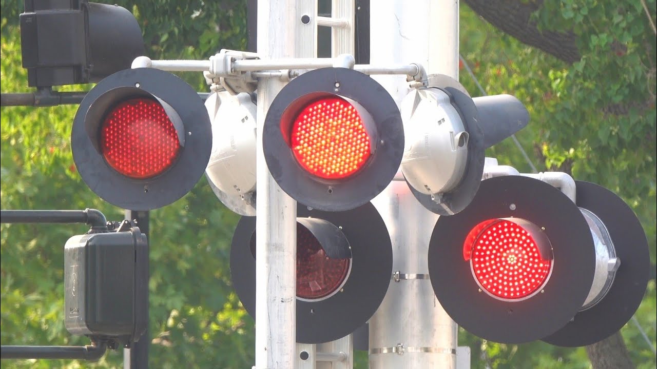
Here's my part 1 video of Safetran Fading LEDs Light railroad crossings compilation. These LEDs were heavily used on different Light rail and commuter rail transit line companies and by CN Railway. UP and BNSF also have used these LEDs lightly with UP using them in the early 2000s on there 1990s to early 2000s Safetran EM Install signals. BNSF u...
 pine bramble
Ok. Only because I’m trying to be helpful. I’m not a wonderful programmer. But wouldn’t you use a brightness value and decrease by 1 over a volume of time?
livid osprey
fallow valve
how I can do a fade when I have Two LEDS going back and forth? - I was gonna bui...
Depends on what hardware you’re using to drive the LEDs. I believe you can analogWrite() to PWM capable pins to adjust brightness over time, or use an external LED driver like AW9523 and its libraries to do basically the same thing a little bit more reliably.
fallow valve
I'm aming to use the Pins then fad them out like the Safetrain LEDs
 steel oak
If anyone fancied helping me with this that would be lovely: https://github.com/samuk/ESP32-robot-car-controller/blob/main/src/main.cpp Compile errors: rc/main.cpp:50:2: error: expected unqualified-id before 'while'
while (!Wire.begin(I2C_SDA, I2C_SCL, 100000ul)) { // standard wire pins
^~~~~
src/main.cpp:55:5: error: 'commander' does not name a type

GitHub
ESP32-based wifi robot controller. Contribute to samuk/ESP32-robot-car-controller development by creating an account on GitHub.
livid osprey
fallow valve
I'm aming to use the Pins then fad them out like the Safetrain LEDs
https://www.arduino.cc/en/Tutorial/BuiltInExamples/Fade/ would be a good place to start?

Open-source electronic prototyping platform enabling users to create interactive electronic objects.
 spring sand
Hello, I recently attended the Adafruit Ask an Engineer and asked the following,"Are there any upgrades to the RA8875 board". The responded WITH,"There are no upgrades and the chip is about to be discontinued in the future. I have a project that uses a 5" or 7" display and need touch support and color. I have already checked to see if there was just a plain touch layer with there is but the controller is discontinued too. This is so frustrating and I need some help. Because of the driver board being discontinued, I would like to improve the screen. Maybe an OLED with touch or even just an OLED and a 5" touch resistive layer with a controller. I am using an Arduino and it needs to be compatible. Thanks for all the help!
RA8875:https://www.adafruit.com/product/1590
Resistive touch layer:https://www.adafruit.com/product/333
Resistive touch layer controller (Discontinued):https://www.adafruit.com/product/1571

Have you gazed longingly at large TFT displays - you know what I'm talking about here, 4", 5" or 7" TFTs with up to 800x480 pixels. Then you look at your Arduino. You love ...

Want to poke at your projects? This resistive touch screen can be used with a stylus or fingertip and is easy to use with a microcontroller. You can put it over a paper overlay for a touch ...

Getting touchy performance with your screen's touch screen? Resistive touch screens are incredibly popular as overlays to TFT and LCD displays. Only problem is they require a bunch of ...
 eternal cloud
spring sand
Hello, I recently attended the Adafruit Ask an Engineer and asked the following,...
eternal cloud
spring sand
Hello, I recently attended the Adafruit Ask an Engineer and asked the following,...
The driver board will be discontinued in the future, but it's in stock now ... so are the TFT panels, touch layers, and the new touch layer controller https://www.adafruit.com/product/5423
I'm not sure I understand what do you need help with...
 wind drift
Question:
I have some LED filament (3.3v). Do I need to use a 220 ohm resistor with it?
They use max. around 80mA
I would like to use an arduino to control the intensity - do I need a LED driver for this (which one)? Or something else?
 leaden walrus
is 3.3V the forward voltage of the LEDs? or what you want to use for power?
for brightness, can PWM, don't really need a driver, other than dealing with powering
spring sand
eternal cloud
The driver board will be discontinued in the future, but it's in stock now ... s...
I am using the screen and am going to need the driver in the future and was wodering if there was an alternatve so i could order it
 sage anvil
@gilded swift thanks for all the help, finally got it working 🙏
 eternal cloud
spring sand
I am using the screen and am going to need the driver in the future and was wode...
eternal cloud
spring sand
I am using the screen and am going to need the driver in the future and was wode...
I couldn't find any alternative products that didn't use the same chip...
Unfortunately, with end of life products, the best you can do is buy a few of them while you still can.
 native kelp
how can i do an async post request with an application/json body type on an esp32, i've found multiple libraries that can do async post requests supposedly but i havent found an example of how to actually do a post request with the application/json body type
pine bramble
DigiKey sold me an STM32F407 Discovery board, which their stock reporting system said there was only one of. Usual price (USD $19.xx).
The stock amount did not drop to zero. I suspect that means they have a pile of them but wanted to discourage multiple unit sales, to have a small supply on-hand, ready for the next buyers in line. ;)
/just-a-guess
pine bramble
pine bramble
DigiKey sold me an `STM32F407 Discovery` board, which their stock reporting syst...
I’m p new to the hobby electronics. What does one do with this?
pine bramble
pine bramble
I’m p new to the hobby electronics. What does one do with this?
https://www.adafruit.com/product/4382
https://www.adafruit.com/product/4877
https://learn.adafruit.com/adafruit-stm32f405-feather-express
https://circuitpython.org/board/feather_stm32f405_express/
But I use it for:
Dr. C.H. Ting's eForth
https://github.com/wa1tnr/eforth-stm32f4x-a/tree/master/0-Distribution.d
All the STM32F4xx boards have basic similarities.
The Discovery has pre-soldered header pins (lots and lots of them) and it was twenty dollars.
I forgot stm32duino:
https://github.com/stm32duino/Arduino_Core_STM32
pine bramble
pine bramble
The Discovery has pre-soldered header pins (lots and lots of them) and it was tw...
For 20 bucks maybe I’ll order one.
I didn’t care for python. But I like messing about
spring sand
eternal cloud
I couldn't find any alternative products that didn't use the same chip...
Unfor...
Yep but the worst thing is that thwh ate SO Pricey ~=30 something like that 🤯
spring sand
How do you use the adafruiut library for oled and print text then erase it and then write new text?
 stable forge
spring sand
How do you use the adafruiut library for oled and print text then erase it and t...
stable forge
spring sand
How do you use the adafruiut library for oled and print text then erase it and t...
may be helpful, and there will be Arduino examples in those libraries
spring sand
stable forge
continuing from previous: <https://learn.adafruit.com/adafruit-gfx-graphics-libr...
It helped alittle thank you!
 wet crystal
Hello people, I feel like im to stupid to find a solution on the internet, so I ask here 😄
I recently bought a VESC (open source speed controller)
You can attach a bluetooth dongle to it so you can simply use bluetooth to setup or change settings, but I dont have one here. But i have an ESP32.
So I wanted to know if someone can point me to what kind of sketch I need to put onto the ESP to make it act like a bluetooth dongle over UART.
thx in advance
cedar mountain
wet crystal
Hello people, I feel like im to stupid to find a solution on the internet, so I ...
That's honestly going to be a crap-ton of work. Just buy a $5 dongle...
wet crystal
Lol I thought it would be easy 😄
cedar mountain
Perhaps I misunderstood. By "dongle" I'm assuming you mean a USB device that would need to be emulated. Or do you actually mean a Bluetooth serial "module" that just gives you TX/RX wires to connect?
 rough nova
fallow valve
how I can do a fade when I have Two LEDS going back and forth? - I was gonna bui...
rough nova
fallow valve
how I can do a fade when I have Two LEDS going back and forth? - I was gonna bui...
I've built a LEGO crossing gate with Mindstorms 1.0, and can offer some clues. But, I've also helped maintain crossing gates on real train level crossings, and the electronics aren't fading the LEDs... there are two channels, and one is on while the other is off. Your eyes (persistance of vision) are the "fade" you perceive.
For my signal model, the program used Micromotors to lower and raise the gates... turning them on in one polarity to lower for a period of time, and then waiting until the train was done... then change the polarity, and run them again to raise the gates. Mechanical stops for the raised and lowered positions did the work, and the micromotors have a bit of slip.
The train was detected using a small reed-switch, in between the studs of a 2x4 plate, and laid across the center stud on a couple adjacent ties. When the magnet couplers on the train come across, the Mindtorms see a series of pulses... which start the leds flashing and wait a few secs, then lower the gate...if the pulses are still there, rest a small loop... when the pauses stop, raise the gates, then stop the flashing.
 steel lynx
hey, is it possible to use the microSD slot on the back of some of adafruit's displays for, say, logging functionality? just wondering if that's strictly for loading images or if you can re-purpose it for other stuff
wet crystal
cedar mountain
Perhaps I misunderstood. By "dongle" I'm assuming you mean a USB device that wou...
Yes
I think that what I mean
wet crystal
The VESC has UART pins with rx and tx, which you usually put a bt module onto. I just wanted to use the ESP32 I got plenty off
 rough torrent
steel lynx
hey, is it possible to use the microSD slot on the back of some of adafruit's di...
rough torrent
steel lynx
hey, is it possible to use the microSD slot on the back of some of adafruit's di...
Yes, it's like an uSD breakout board combined with the TFT breakout
livid osprey
wet crystal
The VESC has UART pins with rx and tx, which you usually put a bt module onto. I...
Projects like https://github.com/coddingtonbear/esp32-bluetooth-bridge exist, but may need extra work to configure properly?

GitHub
ESP32 Bluetooth to UART Bridge (Replaces HC-05). Contribute to coddingtonbear/esp32-bluetooth-bridge development by creating an account on GitHub.
wet crystal
livid osprey
Projects like https://github.com/coddingtonbear/esp32-bluetooth-bridge exist, bu...
This seems like what im looking for a HC-05 replacement
wind drift
Probably a dumb question but I am using a LiPo battery and have a TP4056 breakout board connected for charging.
I have already replaced the resitor with an appropriate one.
How do I know it is charging 'safely'?
Do I just measure the voltage on Vin?
 slim shell
Are there interrupt pins on the Grand Central m4 Express?
 chilly plover
I know on a Mega you assign an interrupt to a pin. Only some pins support it. I'm guessing the M4 is going to work the same.
livid osprey
slim shell
Are there interrupt pins on the Grand Central m4 Express?
There should be plenty of them, IIRC almost all of them are interrupt-capable?
chilly plover
I may be thinking of timer outputs.
livid osprey
Maybe, maybe not? I don't think the Mega shares that characteristic with the SAMD51...
 brazen falcon
wind drift
Probably a dumb question but I am using a LiPo battery and have a TP4056 breako...
brazen falcon
wind drift
Probably a dumb question but I am using a LiPo battery and have a TP4056 breako...
If you have the TP4056 board with the DW01A chip also it should be stopping the most dangerous scenarios.
There's always some inherent risk with LiPos though
brazen falcon
Note that the cheap chinese tp4056 boards typically don't give you maximum benefit out of the protection, they generally give you overcurrent/short protection only. No protection from over/undercharging or plugging in the battery backwards.
 plain shoal
hi how can i change the sda and slc pins, im using a stm32 blue pill. im trying to with softwire library but it doest compilled fine. has anyone done this or have an idea to solve it. also SOFT FAST doesnt work
 strange cradle
Hi Everyone. I have a patch for an old Adafruit product: The WaveHC library for the WaveShield. I am the manager of a makerspace at a k-12 school. We have a few of these lying around so I wanted to makers who are familiar with 8 bit Arduinos to try them out. Unfortunately, I ran into https://github.com/adafruit/WaveHC/issues/3. I put up a PR for this and was wondering if anyone cares anymore about patching a product that I first used in 2009, and if so, if this was the right place to talk about it.

GitHub
The WaveHC Library was developed for the Adafruit Arduino Wave Shield. - Issues · adafruit/WaveHC
For the record, I have been moving the school to use something like a Feather or a Pico, but everyone who has taken engineering classes for the past 9 years or so cut their teeth on these Arduino Unos and Nanos.
The pull request is up at https://github.com/adafruit/WaveHC/pull/5. I'm happy to work further to help make a release of the library. It would be great if our makers and engineering students could just use the Arduino library manager to pull in a working version of the code by default.\

GitHub
GitHub is where people build software. More than 83 million people use GitHub to discover, fork, and contribute to over 200 million projects.
eternal cloud
plain shoal
hi how can i change the sda and slc pins, im using a stm32 blue pill. im trying ...
The I2C pins are predefined, you have to check the pinout for your board, see which pins are labeled SDA/SCL (or SDA1/SCL1, 2, depending on how many I2C busses are available), and use those.
Also, please don't post the same message in multiple channels.
 light yacht
hi i recently purchased an adafruit as7341 spectrometer and am trying to get the demo code working but it keeps coming up on my serial monitor that it cant find it . im pretty sure i have it all wired up correctly and have my arduino setup correctly too . any ideas as why this might be ?


 shut prism
light yacht
hi i recently purchased an adafruit as7341 spectrometer and am trying to get the...
shut prism
light yacht
hi i recently purchased an adafruit as7341 spectrometer and am trying to get the...
Check that your address for the module is 0x39 in the code. Check that your connections are properly plugged into the correct pins. Can't tell from the picture angle you sent.
light yacht
#include <Adafruit_AS7341.h>
/* This example will read all channels from the AS7341 and print out reported values */
#include <Adafruit_AS7341.h>
Adafruit_AS7341 as7341;
void setup() {
Serial.begin(115200);
// Wait for communication with the host computer serial monitor
while (!Serial) {
delay(1);
}
if (!as7341.begin()){
Serial.println("Could not find AS7341");
while (1) { delay(10); }
}
as7341.setATIME(100);
as7341.setASTEP(999);
as7341.setGain(AS7341_GAIN_256X);
}
void loop() {
// Read all channels at the same time and store in as7341 object
if (!as7341.readAllChannels()){
Serial.println("Error reading all channels!");
return;
}
// Print out the stored values for each channel
Serial.print("F1 415nm : ");
Serial.println(as7341.getChannel(AS7341_CHANNEL_415nm_F1));
Serial.print("F2 445nm : ");
Serial.println(as7341.getChannel(AS7341_CHANNEL_445nm_F2));
Serial.print("F3 480nm : ");
Serial.println(as7341.getChannel(AS7341_CHANNEL_480nm_F3));
Serial.print("F4 515nm : ");
Serial.println(as7341.getChannel(AS7341_CHANNEL_515nm_F4));
Serial.print("F5 555nm : ");
Serial.println(as7341.getChannel(AS7341_CHANNEL_555nm_F5));
Serial.print("F6 590nm : ");
Serial.println(as7341.getChannel(AS7341_CHANNEL_590nm_F6));
Serial.print("F7 630nm : ");
Serial.println(as7341.getChannel(AS7341_CHANNEL_630nm_F7));
Serial.print("F8 680nm : ");
Serial.println(as7341.getChannel(AS7341_CHANNEL_680nm_F8));
Serial.print("Clear : ");
Serial.println(as7341.getChannel(AS7341_CHANNEL_CLEAR));
Serial.print("Near IR : ");
Serial.println(as7341.getChannel(AS7341_CHANNEL_NIR));
Serial.println("");
}
thats from the adafruit example setup code from this link https://download.kamami.pl/p587269-adafruit-as7341-10-channel-light-color-sensor-breakout.pdf
shut prism
So it's failing to find your device. It's not really running much code from the library there. So it most likely is your connections. Verify everything is connected correctly.
Looks like a genuine module, so I don't think the address is incorrect. Though you can run an i2c scanner example to verify
livid osprey
light yacht
hi i recently purchased an adafruit as7341 spectrometer and am trying to get the...
Your headers aren’t soldered, so your header pins aren’t making solid contact with the breakout board.
shut prism
livid osprey
Your headers aren’t soldered, so your header pins aren’t making solid contact wi...
Oh I didn't even notice, I need to get my eyes checked that should have been the first thing I noticed.
leaden walrus
light yacht
okay thank you
 quartz river
Is there a device that I can give it (DC) voltage, and if the voltage is below a certain amount, it will output nothing, but otherwise it will let the voltage through? I have a 9v battery, but if it is below a certain threshold, I'd like my circuit to just turn off
cedar mountain
quartz river
Is there a device that I can give it (DC) voltage, and if the voltage is below a...
There are similar undervoltage protection circuits used for things like lithium batteries, to keep them from being discharged too low... they just drive a FET to turn the power path on or off. Possibly you could find one with an adjustable threshold.
quartz river
cedar mountain
There are similar undervoltage protection circuits used for things like lithium ...
I'll look at that - my threshold is simply 5v (or 4v works too) - it isn't anything special :)
cedar mountain
quartz river
I'll look at that - my threshold is simply 5v (or 4v works too) - it isn't anyth...
Generally a 9V battery will be pretty dead long before it gets down to 4 or 5V.
quartz river
cedar mountain
Generally a 9V battery will be pretty dead long before it gets down to 4 or 5V.
Yes, I'd be using a step-down converter. I meant I could put said device either before the converter (at 9v) or after (once it has dropped so much the converter output has decreased)
 fair sorrel
I'm making a multi sensor unit with an Arduino that needs to be able to communicate the sensor totals to various types of data loggers and have been trying to figure out how I want to pass the data across the UART. I've seen Simple Serial Interface and HDLC but I can't find complete information on either of those protocols to implement. Does anyone have a good resource or an alternative serial communication protocol they'd recommend?
cedar mountain
quartz river
Yes, I'd be using a step-down converter. I meant I could put said device either ...
Ah, gotcha. Often step-down converters will have a "power good" output pin that indicates whether they think they're able to achieve the set voltage or not, so you could potentially use that as a signal to your downstream circuit.
quartz river
cedar mountain
Ah, gotcha. Often step-down converters will have a "power good" output pin that ...
Ohhh, I didn't know that. That would work great!
cedar mountain
fair sorrel
I'm making a multi sensor unit with an Arduino that needs to be able to communic...
You might consider just starting with a simple ASCII protocol. You can get pretty far with just "10,50.1,NO_ERR\n" sometimes, heh heh.
fair sorrel
cedar mountain
You might consider just starting with a simple ASCII protocol. You can get prett...
Thanks, haha I will if I don't get any further on established protocols. I'd like to not have another serial protocol since I may end up making more than a dozen if the first two work well.
 north stream
There are things like Firmata that can package and send data for you, or older formats like XDR, but I often end up using simple human-readable ASCII ones like Ed mentioned, as I can just interact with them as transmitter or receiver with a simple terminal program, which can be very handy for debugging.
wet crystal
Hello again.
Im currently working on Ninebot Turn Light board.
It has a STM8 Proccessor on it, which wait for a CAN Bus command to be activated. Since that would require too much work I was thinking about to just overwrite the Output pins.
I just found two IC´s which seems to have TIM TM1911 written on it, but google just shows me just the 1911 gun when googling for it.
Than I made some drawing and saw the 1911 is connected to the TIM pins on the STM8.
Little bit of googling told me that it could be timers PWM based.
Does someone have more informations about that?
cedar mountain
wet crystal
Hello again.
Im currently working on Ninebot Turn Light board.
It has a STM8 P...
Could be a Titan Micro LED driver chip, though I don't know the exact part number.
wet crystal
cedar mountain
Could be a Titan Micro LED driver chip, though I don't know the exact part numbe...
I thought those might be some Kind of timer chips, which could be driven by pwm
Does those kind of chips exist?
cedar mountain
I'm not sure. The PWM output might also be used as a smart-LED data protocol like Neopixels use.
wet crystal
Lets hope it not 😄
wet crystal
cedar mountain
I'm not sure. The PWM output might also be used as a smart-LED data protocol lik...
But also wouldnt that be quite op for an indicator that has just 3 leds inside 😄
But well lets wait
I ask my friend to return his scooter, I plug in the board and just put an pwm onto that chip with a separat arduino, is there a risk of frying anything or na?
cedar mountain
Yeah, injecting signals into an unknown circuit can sometimes fry things. Ideally you'd measure the existing functionality first with an oscilloscope.
wet crystal
cedar mountain
Yeah, injecting signals into an unknown circuit can sometimes fry things. Ideall...
Its not functioning thats the issue
The STM8 waits for activation signal from can bus, which I have absolute no chance of grabbing
 hushed frigate
I have an Arduino micro and an Ultimate GPS breakout v3. What program should i be running and how should i be wiring it?
I saw the earlier response, I have seen https://learn.adafruit.com/adafruit-ultimate-gps but I am still unsure about how exactly to do it

Adafruit Learning System
One GPS to rule them all and in the darkness find them!
north stream
It's a fairly simple serial device. There's an Arduino library that makes it fairly easy to talk to.
 crimson lark
Is anyone willing to help with arduino servos right now
We can vc
It'd be really helpful and will only take 5 minutes of your time
north stream
It might help if you described the problem you're trying to solve.
eternal cloud
hushed frigate
I have an Arduino micro and an Ultimate GPS breakout v3. What program should i b...
The guide gives a detailed description of the pins on the GPS breakout: https://learn.adafruit.com/adafruit-ultimate-gps/pinouts,
and the pinouts for the arduino micro are in their documentation:
https://docs.arduino.cc/hardware/micro
+
https://docs.arduino.cc/static/777a1c066b7b2060eba932b9cc3eed5a/A000053-pinout.png
The guide also shows the wiring for Arduino: https://learn.adafruit.com/adafruit-ultimate-gps/arduino-wiring (Hardware Serial Boards). You need to connect the coin battery on the back of the GPS, between 3 to 5V to the VIN pin, ground, Rx from one board to Tx on the other, and Tx to Rx
eternal cloud
crimson lark
We can vc
This is a space for public help: you state your problem, people who know about it contribute, everyone wins (and learns).
People rarely volunteer to pm / vc, and problems rarely "only take 5 minutes" to solve 😛
pine bramble
eternal cloud
This is a space for public help: you state your problem, people who know about i...
But if you could just sit through my presentation on vacation sharetimes. It’s only going to take 5 mins.
wind drift
I am having trouble with using a capacitive touch sensor + wireless charger.
Basically I want to activate something with the capacitive touch sensor - which works fine on its own
But once I have a wireless charger for my battery connected it's not working properly
Do I need to separate the ground from the wireless charger and the capacitive touch sensor? Or keep the same ground?
north stream
I had what might be a similar issue a while back, where a capacitive touch sensor had a different sensitivity when powered by a plug-in supply versus a battery supply (presumably because the plug-in supply gave a higher capacity feedback path). If it's something like that, you can either write some adaptive code to try to set the threshold depending on current conditions, have a configuration adjustment of some sort, or just stick with one kind of power supply.
Your idea of isolating the supply somehow is a good one, I didn't try that, but it might simplify the problem.
wind drift
ah the isolation part does not seem to work with my setup
So basically I have an LED that turns on with capacitive touch.
It is powered by a LiPo battery. Which is charged by a TP4056 breakout board. Which is powered by the wireless charger.
The TP4056 breakout board V-in and V-out share the same ground
 wind drift
Would I maybe have to use a diode? Just not sure where to place it
 sacred ivy
Is there a way to convert ASCII characters back into binary? So want to control PWM from a serial port and Ive gotten the numbers, but, they are all in ASCII form. So the decimal number "1024" has the associated ASCII characters for each number. I need to take those numbers and put it into something readable so I can shove it into a register.
 gilded swift
sacred ivy
Is there a way to convert ASCII characters back into binary? So want to control ...
gilded swift
sacred ivy
Is there a way to convert ASCII characters back into binary? So want to control ...
You might be able to static_cast to an int to get the ascii value
You would need to loop over the incoming string (char array) and convert each char to an int
You can subtract “0” to convert to straight int:
int num = static_cast<int>(str_char-“0”);
It’s probably slightly more nuanced but that’s the general idea
Syntax is slightly wrong though
cedar mountain
The library functions atoi() or sscanf() may be useful.
gilded swift
That was my other thought. Looks like you could also do it implicitly by doing
int num = str_char - ‘0’
 terse lava
With the Feather RP2040 using &WIRE1, do you essentially need to modify every library and their dependencies to change &WIRE to &WIRE1? even if wire.h isn't used in the example sketch? Just trying to understand how to work with it. For things like the OLED featherwing, I can change it in the device declaration before setup, but sensors like the LTR329 don't include &WIRE in the sketch
cedar mountain
It'll just depend on the library. Often you can pass in a Wire reference to the constructor, but if the library has the I2C bus hard-coded, there's not much you can do but edit it in the library.
terse lava
cedar mountain
It'll just depend on the library. Often you can pass in a Wire reference to the ...
Thanks! I found only one line in the library mentioning &WIRE, but modifying it to &WIRE1 doesn't seem to have an effect.
bool begin(TwoWire *theWire = &Wire);
 tacit jewel
how do I fix this error in platform io I'm trying to use the debugger avr_stub on a arduino mega 2560
 north stream
wind drift
Would I maybe have to use a diode? Just not sure where to place it
north stream
wind drift
Would I maybe have to use a diode? Just not sure where to place it
You could tack an external conductive object to the ground pin to increase capacitive coupling to the surroundings
north stream
tacit jewel
how do I fix this error in platform io I'm trying to use the debugger avr_stub o...
It looks like it's trying to attach to a device that isn't there. You may need to specify the target or debugger port differently (note that the port can change unexpectedly, causing this error to recur)
tacit jewel
the usb port on the arduino when I plug it in to the computer it comes in as COM10
is the debug serial port different than the usb
cedar mountain
terse lava
Thanks! I found only one line in the library mentioning &WIRE, but modifying it ...
So this means you should be able to pass in &Wire1 when your code calls begin() and not need to edit the library at all.
terse lava
cedar mountain
So this means you should be able to pass in &Wire1 when your code calls begin() ...
Compiles without error but doesn't seem to report data. I'll have to take a further look at this in the morning, thank you very much for the assistance!
leaden walrus
terse lava
Compiles without error but doesn't seem to report data. I'll have to take a furt...
try this I2C scanner sketch:
https://learn.adafruit.com/scanning-i2c-addresses/arduino-using-testbed
to see if any addresses can be found. sketch should take care of scanning both Wire and Wire1
for the Feather RP2040, the I2C ends up being Wire1:
https://learn.adafruit.com/adafruit-feather-rp2040-pico/pinouts#stemma-qt-3084853
STEMMA QT pins and headers pins for SCL/SDA are same for Feather RP2040
 tender sinew
Hi, I'm thinking of doing the blob detection of my ants.
I just found out about arduino portenta and OpenMV that allows me to do blob detection stuff.
But I see that there are several different models of this
H7, H7 Lite, X8, and what is Vision Shield?
I don't know what to get.
I am thinking of sending the live data into another microcontroller called Daisy Seed
so that it can get live data from Arduino Portenta and use it for synthesizing sounds
 tribal cipher
Dear members. How can I switch from one dc power source to another? As of now I'm using Oring diode Configuration. I want to power the Arduino in case of power failure. Please guide.
pine bramble
tribal cipher
Dear members. How can I switch from one dc power source to another? As of now I'...
Why can’t you parallel them with a diode to block drainage current?
tribal cipher
pine bramble
Why can’t you parallel them with a diode to block drainage current?
I'm have connected them in parallel
tribal cipher
pine bramble
Why can’t you parallel them with a diode to block drainage current?
Please guide on this one

This is my current configuration
pine bramble
Isn’t that essentially what you have?
tribal cipher
pine bramble
Isn’t that essentially what you have?
Are there any other methods for the same? I mean to switch power?
pine bramble
tribal cipher
Are there any other methods for the same? I mean to switch power?
I’m not sure I’d be the best at exact science for it. I’d be looking at diodes and I’m aware they do it in solar systems. Just a heads up on where to research.
pine bramble
https://www.utmel.com/blog/categories/diodes/schottky-diodes-principle-functions-and-applications
@tribal cipher look at the dual power section might be of help

Schottky diodes are metal-semiconductor devices made of precious metals (gold, silver, aluminum, platinum, etc.) A as the positive electrode and N-type semiconductor B as the negative electrode. Schottky diodes are unidirectionally conductive and can convert alternating currents into pulsed direct currents in a single direction.
tribal cipher
pine bramble
https://www.utmel.com/blog/categories/diodes/schottky-diodes-principle-functions...
Will read it right away
 blazing crane
I'm encountering the same exact issue mentioned here (Nano 33 IoT rather than Nano 33 BLE, but same thing)
Arducam Camera Support Forum
Hello Arducam, I am having problems running the example programs on a setup with an ArduCAM Mini 2MP Plus and an Arduino Nano 33 BLE Sense board. It looks like the basic operation of the ArduCAM is working, looking at the console output, but the captured image does not appear in a new window (with the exception of 1 time out of maybe 50 or 100 ...
There really didn't seem to be an answer on this forum post, so I was wondering if y'all had any ideas
I pretty much tried all the steps as discussed in the post as well and got the exact results they described (works maybe 1% of the time, works perfect on an Uno, etc.)
leaden walrus
some kind of hardware conflict? maybe i2c address conflict?
with the items on the nano. like the ublox module or the crypto auth chip.
blazing crane
any idea how I'd check that?
(Also I'm pretty sure the guy in the post mentioned he narrowed it down to the transmission with the PC over Serial but I haven't tested that so I can't say for sure)
leaden walrus
can you connect to the serial monitor output while running the sketch?
 edgy bolt
Hi, is there any documentation for Adafruit_TinyUSB_Arduino library, so I can understand it easierly
pine bramble
edgy bolt
Hi, is there any documentation for Adafruit_TinyUSB_Arduino library, so I can un...

GitHub
Arduino support for TinyUSB stack. Contribute to adafruit/Adafruit_TinyUSB_Arduino development by creating an account on GitHub.
edgy bolt
ye, but that doesnt explain anything
blazing crane
leaden walrus
can you connect to the serial monitor output while running the sketch?
from Uno

(lemme grab from Nano 33)
blazing crane
@leaden walrus Ok, so the 33 is not sending periodic Serial messages like the Uno is
Occasionally I'll get a couple but it's inconsistant
The only stable message I get is when I unplug the camera it spams the Serial Monitor with "SPI Interface Error" or something like that
leaden walrus
those might help narrow down where in the code things are stalling?
blazing crane
Well, since that was just the example program, I only just needed it as a starting point/useful for debugging. I just used the Uno when I still needed their example tools. My new custom program works on the IoT fine so idk what's up with their code lol
Now I just gotta do some Googling on how to parse a jpeg file
tacit jewel
with a arduino zero can you use the native usb for serial output and debug at the same time because when I debug it disconnects from windows
leaden walrus
@celest basalt please ask arduino related questions in this channel. which step of the guide is not working as shown?
https://learn.adafruit.com/rp2040-arduino-with-the-earlephilhower-core
 celest basalt
leaden walrus
<@720278340552097812> please ask arduino related questions in this channel. whic...
celest basalt
leaden walrus
<@720278340552097812> please ask arduino related questions in this channel. whic...
its not that it's not working, i'm just asking whether i have to do this
leaden walrus
if you want to program the pico with arduino, yes
celest basalt
leaden walrus
if you want to program the pico with arduino, yes
i mean do i have to program it with arduino for the LCD to work
leaden walrus
you're working with an LCD that has an arduino library, but not a circuitpython library?
celest basalt
leaden walrus
you're working with an LCD that has an arduino library, but not a circuitpython ...
oh
ok
stable forge
@celest basalt you were using my CircuitPython library to try to get that PCF8574 LCD display to work. I suggested that you try it with an Arduino library to see if it worked under other circumstances. I also said that it might need a level shifter to work properly, even if it was sort of working by responding to the i2c.scan().
celest basalt
stable forge
<@720278340552097812> you were using my CircuitPython library to try to get that...
okay
celest basalt
stable forge
<@720278340552097812> you were using my CircuitPython library to try to get that...
can i use arduino together with circuit python or not
stable forge
celest basalt
can i use arduino together with circuit python or not
No, they are separate. I was just suggesting testing the display with Arduino to see if you could get it to work.
leaden walrus
if you're using a board with spi flash, then arduino generally won't erase those unless you run a sketch that does so.
but easy enough to just save local copies of everything
libraries can always be redownloaded
once the hardware has been sanity checked with arduino, can easily go back to circuitpython
celest basalt
leaden walrus
once the hardware has been sanity checked with arduino, can easily go back to ci...
okay so i should save the files locally
then once the display has been checked with arduino I drag everything back into
ykw i'll just do that as my last step
north stream
I like to save my files locally anyway, for review/re-use as well as a backup.
celest basalt
okay
cedar mountain
This line looks a little weird: lastCount != count;Normally I'd expect that to just have a normal =.
Also you might want to play around with the "50" parameter in the debounce configuration... possibly it's not a perfect match for your button when it's being pressed rapidly.
 fresh pendant
Hi! I could use a hint for what to try. I've got an esp32-s2 tft feather that I've previously programmed with Arduino. I wanted to update the program, but after I "successfully" upload the sketch it only shows me the tinyuf2 bootloader screen, and my program doesn't start. I'm still on Arduino 1.8.16 but I made sure the esp32 package was up to date in the boards manager.
I've tried fully erasing the board and "flash bootloader" but neither has changed what I'm seeing.
The upload says it ended with an error but it's just that I am supposed to press reset manually:
WARNING: ESP32-S2FNR2 chip was placed into download mode using GPIO0.
esptool.py can not exit the download mode over USB. To run the app, reset the chip manually.
To suppress this note, set --after option to 'no_reset'.
An error occurred while uploading the sketch``` fresh pendant
I can install CircuitPython fine as a uf2 🤣 but I was going to use arduino today
gilded swift
I experience the same thing
livid osprey
fresh pendant
Hi! I could use a hint for what to try. I've got an esp32-s2 tft feather that I'...
Is there anything hooked up to the board? The error suggests there may be something pulling GPIO 0 a way the board doesn’t like…
gilded swift
For whatever reason if you try to do after=soft_reset uploads fail on esptool. It’s likely not a huge issue
fresh pendant
No, the "GPIO 0" thing is totally expected -- It happens anytime you have to use the reset button + boot button to enter the bootloader
it is in a feather quad with 3 other boards that are I2C displays, I'll pull it out and repeat the bootloading process to see what happens.
same without the other featherwings connected --- after uploading sketch from arduino, it shows the uf2 bootloader screen
@gilded swift did you test and see the same problem?
or did you mean the thing about GPIO 0 you also experience?
fresh pendant
but when you DO reset it you get your sketch and not uf2
gilded swift
Yeah
fresh pendant
I should try a different sketch I guess, but my sketch worked last time I uploaded it .. which was months ago
OK a different sketch is not affected. so that says something.
Global variables use 54356 bytes (16%) of dynamic memory, leaving 273324 bytes for local variables. Maximum is 327680 bytes.
``` plenty of space left overprobably
well I hate these kinds of things but I updated all my libraries and removed a damaged one (FreeRTOS-Arduino) and now I can enter my sketch again
but it's still having network problems
fresh pendant
OK, well, most of the problems seem to have been operator error. I'm up and running again. Thanks!
 trim zodiac
Hello
I am uploading this code to my Circuit Playground using avrdude on a raspberry pi 4: https://github.com/pokir/arduino-bare-metal-blinking-led
this program resets the board using 1200 bps touch reset method in src/reset.py (like https://github.com/arduino/arduino-cli/blob/7415e269061ff4d90e6356f6c1156941122d58c3/arduino/serialutils/serialutils.go#L30-L56) and then uploads the code in src/led.c using avrdude (everything is in the Makefile)
it works fine the first time i upload it, but then once it is uploaded the circuit playground is no longer listed on lsusb
and there are weird error messages in
dmesgafter it showing the circuit playground disconnecting
i also noticed the
idProductandbcdDevicevalues change indmesgafter uploading the code usingavrdude(idk if that is relevant)
the only way to then upload code again using the script is to use the reset button to put the board into bootloader mode and to disable the line that disables dtr in src/reset.py, and then to run make
when i upload any code to it through the Arduino IDE, it fixes all problems and then shows up normally on my raspberry pi while running
Is there something that must be done while uploading to the Adafruit Circuit Playground (Original Developer Edition) to make it not disconnect from USB port?
 daring crypt
Question: I was playing with different examples on my ItsyBitsy nRF52840 Express and it was working with different examples. But then it stopped working after i tried a sketch that probably wasnt right for it (not in the examples folder for the express). I hit reset and got a "No data received on serial port" error after trying to re-upload another sketch. I went into usb bootloader mode and it opened up the usb drive and I can see "CURRENT.UF2" bootloader file.. do i just copy over and rename the "update-bootloader-itsybitsy_m0-v3.7.0.uf2" to "CURRENT.UF2"?
 solemn cliff
daring crypt
Question: I was playing with different examples on my ItsyBitsy nRF52840 Express...
solemn cliff
daring crypt
Question: I was playing with different examples on my ItsyBitsy nRF52840 Express...
just drop the UF2
it's not a real drive, there's no real file, it just flashes the data from the file you drop
daring crypt
oh thanks. Does it have to be named CURRENT.UF2? (i mean, should i rename the update-bootloader.uf2 to CURRENT.UF2) and then drag and drop?
rough torrent
no
daring crypt
i've since dragged and dropped the new bootloader and tried uploading another previously known working sketch, and im still seeing in the logger daemon : "No upload port found, using address /dev/ttyS0" (which was working before.)
daring crypt
i found that I was grounding the wrong pin, and afterwards, it worked to my delight
 silk token
is it a good idea to power a single MG995 servo, and rdm6300 rfid module, and three buttons from the arduino 5v power pin? The servo datasheet says it only uses 350mA, and the rfid only uses 50mA. I have the buttons using the internal pullup resistors.
I get the stk upload error when everything is connected to the power/ground pins but it seems to work if I upload while disconnected, then connecting them.
I was also hoping someone would look at my code and tell me why its actuating the servo on initial startup?
https://github.com/flyingfishfuse/rawr_auto_cat_feederz_uWu/blob/main/main_cat_feeder.ino
livid osprey
silk token
is it a good idea to power a single `MG995` servo, and `rdm6300` rfid module, an...
Should be fine. It may be a bit on the edge of your current limits if you’re powering with usb, but it should be totally fine if you power it with the barrel jack.
Can’t look at your code right now, but what kind of startup movement are you seeing? Is it random movement before your code starts executing, or simply a desire to leave the servo in its current position until otherwise commanded?
silk token
it moves from closed to open, the full 90 degree arc. I am double checking the code after refactoring/cleaning so I am about to test it again but with it in the open position , see if it does the opposite or pushes another 90 degrees in the same direction. The expected behavior is for it to remain in its position pre power up
is it a problem that I have the stk500_getsync() error with the servo and rfid and button board connected? it seems to upload fine if I detach those and plug them in after upload
I think part of the problem is the pin headers on the uno, this board doesnt seem to be too high quality, jiggling the wires seems make it stutter
livid osprey
silk token
is it a problem that I have the `stk500_getsync()` error with the servo and rfid...
Inconvenient, perhaps, but not a serious issue if you have a workaround. Probably a result of the programmer not having enough current to properly run. If you have a barrel jack power supply, see if the second power source helps?
livid osprey
silk token
it moves from closed to open, the full 90 degree arc. I am double checking the c...
A servo without a feedback line has no way to send its current position back to the Arduino. Without external sensing hardware, the best you can do is to save your last position and re-command that position at startup.
silk token
I will try a second power source, I need to wait for some single cell battery clips to arrive for that. I bought some doubles but they were mis advertised as parallel and they were configured as series.... orrr... I think I am gonna cut them apart and reconfigure them, heres to hoping I can solder the stainless before the plastic melts!
edit: i forgot to thank you for your input, my brain isnt right today, sorry lmao
 hoary canopy
If I output an audio signal from an arduino that is wired to the mic in of a radio, do I need to amplify the audio signal?
I'm thinking no, because a normal mic I would plug into there wouldn't be powered... or would it?
north stream
The arduino signal is more or less what's known as "line level", which is more than mic level, so you may need to attenuate (the opposite of amplify) it.
hoary canopy
Is there a way to check if there is continuity on the load side of a relay with the Arduino, without the danger of the high voltage on the load side damaging the arduino? The check would be done before the relay is activated, and would test that the load is conductive at low voltage. Only after will the relay be activated
I saw this image here, but I don't understand how that "continuity test" wire could work https://forum.arduino.cc/t/how-to-input-a-high-voltage-switch/851469


Arduino Forum
Model rocket launch controller. I’ve simplified my schematic. I keep frying my board… How can I input the switch into the board while protecting it from the unregulated current?
I'm doing a similar circuit where a ~12v battery would be connected to a high power load
cedar mountain
hoary canopy
Is there a way to check if there is continuity on the load side of a relay with ...
If I understand the diagram correctly, the continuity test lead is either connected to the battery ground through the igniters (when the relay is closed), or is floating (when the relay is open). So the Arduino can enable a weak pullup and see whether there is continuity through the igniters or not.
If you want to detect a 12V voltage, the simplest thing to do would be to use a simple resistor divider to bring it down to the Arduino logic-level range (3.3V or 5V depending).
hoary canopy
Both options sound good to me. I understand now how that wire works. Checking for ground sure is smarter than checking for positive. I'm leaning towards this option rather than voltage dividers to make sure both system are completely electrically isolated
Thank you very much!
north stream
Another option is an opto-isolator, which can safely detect the presence of voltage without any electrical connection (I'm fond of that particular trick)
hoary canopy
That's a great option as well, thank you!
 foggy anchor
hello, I would like to know if a shift register can duplicate an analog port
cedar mountain
foggy anchor
hello, I would like to know if a shift register can duplicate an analog port
The short answer is no, shift registers are digital circuits so they only deal with 0 and 1 instead of intermediate analog voltages. (The long answer would be more like "well in theory you could use a shift register as a piece of an external ADC or DAC circuit, but...")
foggy anchor
I see but is there a way to duplicate some analog ports?
cedar mountain
The standard way would be via an external ADC or DAC chip, connected by SPI or I2C.
Adafruit Industries, Unique & fun DIY electronics and kits : ADC / DAC - Tools Gift Certificates Arduino Cables Sensors LEDs Books Breakout Boards Power EL Wire/Tape/Panel Components & Parts LCDs & Displays Wearables Prototyping Raspberry Pi Wireless Young Engineers 3D printing NeoPixels Kits & Projects Robotics & CNC Accessories Cosplay/Costumi...
foggy anchor
Okay, I will check that, thank you for your help!
 safe shell
@foggy anchor there's also the option of an analog mux/demux perhaps ...SparkFun has 8- and 16-channel breakouts, if you don't need to access them all simultaneously
foggy anchor
safe shell
<@893971232385560576> there's also the option of an analog mux/demux perhaps ......
Thanks😁
blazing crane
I decided to refactor a lot of my code earlier today, and once I got it back up to a point that's useable, I went to upload it (Nano 33 IoT). After uploading, the board disappeared from the port selections (running ls /dev showed no device so it's not an IDE issue). It sometimes reappears, although it seems to be random (spamming the reset button appears to help). Uploading any other piece of code works without issue. I've also tried with multiple boards and multiple cables. The only thing consistent is that the code I've linked below seems to break things.
I have no idea why, and it's hard to test since even I can't even really upload. Any help is much appreciated!
-Zman
Update: It appears quickly double tapping the rest button make the Arduino wait for a new sketch to be uploaded. That explains why spamming reset helped and only further goes to show that my code is the culprit.
In addition, the line in the main .ino file BeaconCamera camera = BeaconCamera(); seems to be the source. I'm going to follow it deeper and see what exactly causes it
Got it!
 humble pecan
Hello, I recently got a PIR sensor but instead of detecting motion it seems the output just keeps going high and low again. I've tried to edit the sensitivity, time and retriggering settings. But the output continues to cycle from high to low. I'm currently using the example code from Adafruit that I found on this page (https://learn.adafruit.com/pir-passive-infrared-proximity-motion-sensor/using-a-pir-w-arduino). Does anyone know what this could be?
leaden walrus
can you link to specific IR sensor being used. they can vary in terms of output and general functionality.
humble pecan

PIR sensors are used to detect motion from pets/humanoids from about 20 feet away (possibly works on zombies, not guaranteed). This one has an adjustable delay before firing (approx 2-4 ...
leaden walrus
where/how did you edit the sensitivity etc? that doesn't look like a software thing
humble pecan
The PIR sensor has two potentiometers on the back that adjust sensitivity and time.
 leaden walrus
ok. right. and adjusting those is what you mean by "edit"?
humble pecan
I've tried both but currently it is at the H position.
leaden walrus
what's your indication it keeps cycling high/low?
humble pecan
The serial output goes like this:
Motion detected!
5 seconds pass then:
Motion ended!
and then repeats.
I also just made a simple pin reader program and it appears to be saying the same type of information.
leaden walrus
That is happening with constant continuous motion occurring in front of the sensor?
leaden walrus
got the sensor covered up?
humble pecan
No although it is in somewhat small space (about five feet)
leaden walrus
try covering it to make sure nothing is false triggering it
humble pecan
Motion ended! Motion detected! Motion ended! Motion detected! Motion ended! Motion detected! Motion ended!
I covered it up and it's still doing the same thing
leaden walrus
what arduino board are you using?
humble pecan
https://www.adafruit.com/product/5029 The ESP32-S2

Introducing the TinyS2 - The Tiny Mighty ESP32-S2 development board in the TinyPICO format! This board features the powerful ESP32-S2, a single-core Tensilica processor with WiFi and native ...
 oak dragon
Has anyone had success using the internal jtag debugger in the Adafruit ESP32-S3 TFT Feather? I can't seem to get it working properly in vscode/platform.io. It gives me random variable data and doesn't pause at breakpoints.

 atomic lava
i have entirely forgotten how to write in Arduino
north stream
atomic lava
i have entirely forgotten how to write in Arduino
I hadn't in a while and was rusty too, but got going again by looking at some of the examples supplied with libraries I wanted to use and was able to pick up what I needed in an afternoon. You can also go over one or two of the tutorials again to refresh your memory.
 glad thunder
I have a 10k potentiometer wired up to an analog pin that is just reading 0,1,2 no matter where on the dial it is. I checked the continuity and everything is fine (middle to A4, left to 5v+, right to gnd). when I short it out to 5v, the analog reads 1024. what are the next steps in debugging? should I assume a bad pot?

 gilded swift
glad thunder
I have a 10k potentiometer wired up to an analog pin that is just reading 0,1,2 ...
gilded swift
glad thunder
I have a 10k potentiometer wired up to an analog pin that is just reading 0,1,2 ...
Can you show a picture of how you have it wired?
glad thunder
Not easily, my board is a bit of a rats nest
I could draw it in fritzing
I found another pot so I'm going to test to see if the pot is bad
glad thunder
basically
gilded swift
I’d try taking the analog read out of your print statement and assign it to an int variable and then print that int variable
I don’t know how much that changes it. But Arduino can be fickle sometimes
glad thunder
got it!
gilded swift
Nice!
 untold fractal
humble pecan
Hello, I recently got a PIR sensor but instead of detecting motion it seems the ...
untold fractal
humble pecan
Hello, I recently got a PIR sensor but instead of detecting motion it seems the ...
they're sensitive to power supply fluctuations. could you add a capacitor across its power supply pins? say 0.1uF or 1uF?
 ivory ice
Hello! I have experienced some unexpected errors with this bit of code for an esp8266. I keep getting ```C:\Users\bookl\Documents\sketch_oct05a\sketch_oct05a.ino: In function 'void loop()':
sketch_oct05a:15:16: error: expected unqualified-id before '.' token
15 | while (Client.connected() == true) {
| ^
sketch_oct05a:16:17: error: expected unqualified-id before '.' token
16 | if (Client.available() == true) {
| ^
sketch_oct05a:19:19: error: expected unqualified-id before '.' token
19 | Client.println(1);
| ^
sketch_oct05a:30:18: error: expected unqualified-id before '.' token
30 | while (Client.available()== true) {
| ^
sketch_oct05a:31:13: error: expected unqualified-id before '.' token
31 | Client.read();
| ^
exit status 1
expected unqualified-id before '.' token
for the code
`#include <ESP8266WiFi.h>
IPAddress local_IP(192,168,0,1);
IPAddress gateway(192,168,4,9);
IPAddress subnet(255,255,255,0);
WiFiServer server(80);
int laststate = 0;
void setup() {
WiFi.softAPConfig(local_IP, gateway, subnet);
WiFi.softAP("Button");
server.begin();
}
void loop() {
while (Client.connected() == true) {
if (Client.available() == true) {
while (digitalRead(1) == HIGH) {
if (laststate == 0) {
Client.println(1);
laststate == 1;
}
else {
if (digitalRead(1) == LOW) {
laststate == 0;
}
}
}
}
while (Client.available()== true) {
  Client.read();
}
}
}```
Also, i am not sure if it is pertinent, but here is the (networky part) of the code it is meant to interface with
#include <ESP8266WiFi.h>
void setup() {
  WiFi.begin("button");
  client.connect(192.168.0.1, 80)

}

void loop() {
  while (client.read() == 1) {
    digitalWrite(D1, HIGH);
  }
  digitalWrite(D1,LOW);
}
thank you
solemn cliff
ivory ice
Hello! I have experienced some unexpected errors with this bit of code for an es...
it's complaining about Client, what is Client ? Did you mean server ? or client
looks like tou need something like
WiFiClient client = server.accept();
i had smth like that but in the process of debugging i changed it
ivory ice
solemn cliff
looks like tou need something like
```c
WiFiClient client = server.accept();
```
should that be in the loop or setup?
solemn cliff
that would be in the loop, it's where the server reacts to a client connecting
ivory ice
solemn cliff
looks like tou need something like
```c
WiFiClient client = server.accept();
```
it raises the error ```'class WiFiServer' has no member named 'accept'; did you mean '_accept'?
oh I don't know then
ivory ice
ok onto stack overflow then. thanks for trying
ivory ice
alright so I needed to change server.accept() to server.available() thanks for your help
solemn cliff
interestingly googling ESP8266WiFi leads to the "latest" version version that uses accept() but the "stable" (3.0.2) version uses available()
apparently it's an API change to match other APIs with available marked as deprecated, but that has not made its way to a release yet
https://github.com/esp8266/Arduino/pull/8419
ivory ice
read the response to my stack overflow question- https://stackoverflow.com/questions/74202175/esp-8266-wifi-library-class-wifiserver-has-no-member-named-accept-did-you

Stack Overflow
error: In function 'void loop()': sketch_oct05a:15:30: error: 'class WiFiServer' has no member named 'accept'; did you mean '_accept'?
15 | WiFiClient client = server.accept();
| ...
wind drift
I am using the MPR121 capacitive touch sensor.
https://learn.adafruit.com/adafruit-mpr121-12-key-capacitive-touch-sensor-breakout-tutorial/electrodes
I want to power it with a battery and also via USB.
It seems the sensor calibrates when booting. If I have it booted while connected to USB it works fine. But once I remove the USB cable and is powered via the battery it doesn't work anymore.
Is there a way to avoid this?
I guess I would have to detect when the USB is connected/disconnected and recalibrate the sensor each time? Or is there a better approach?

Adafruit Learning System
Get a little closer...closer...now touch it!
And is there a command I can use to recalibrate it?
leaden walrus
what is your indication that it is not working?
 red monolith
Can I have one Arduino nano digital write out to the digital in pin of another nano. This only needs to be a one way message. I can’t seem find a clear answer. Any help is appreciated.
leaden walrus
yes
strange cradle
wind drift
And is there a command I can use to recalibrate it?
From reading the code at https://github.com/adafruit/Adafruit_MPR121/edit/master/Adafruit_MPR121.cpp, it appears that it is safe to call 'begin()' again which will reclaim any previous values and reset the device.
ivory ice
alright sorry to keep pestering y'all, but i got my code to upload, but its not working. Where am I going wrong. The wifi network shows up. server: ```#include <ESP8266WiFi.h>
IPAddress local_IP(192,168,0,1);
IPAddress gateway(192,168,4,9);
IPAddress subnet(255,255,255,0);
WiFiServer server(80);
int laststate = 0;
void setup() {
WiFi.softAPConfig(local_IP, gateway, subnet);
WiFi.softAP("Button");
server.begin();
}
void loop() {
WiFiClient client = server.available();
while (client.connected() == true) {
if (client) {
while (digitalRead(1) == HIGH) {
if (laststate == 0) {
client.println(1);
laststate == 1;
}
else {
if (digitalRead(1) == LOW) {
laststate == 0;
}
}
}
}
while (client.available()== true) {
  client.read();
}
}
}and the client#include <ESP8266WiFi.h>
WiFiClient client;
void setup() {
WiFi.begin("button");
client.connect("192.168.0.1", 80);
}
void loop() {
while (client.read() == 1) {
digitalWrite(1, HIGH);
}
digitalWrite(1,LOW);
}``` thanks for your help
fallow valve
as for my little LEGO Crossing Gate with an actual moving gate - are there any small motors I could use to make my own gate mech using this for those motors? https://www.thingiverse.com/thing:2654720

This is a OpenSCAD customizable reduction from the 500 dc motor by MIG shaft to the lego axle. If not fits, try to edit it in OpenSCAD. We build it for motorized lego robots.
strange cradle
wind drift
<@681940552572338203> 'begin' was not declared in this scope
Can you post your failing code with pastebin or something like that?
north stream
fallow valve
as for my little LEGO Crossing Gate with an actual moving gate - are there any s...
You can use AdaFruit part number 3810 to adapt an ordinary "TT" style motor to a Lego axle, or part number 4252 to adapt a micro servo to a Lego axle.
fallow valve
Servos are a bit fast and unrealstic
north stream
A servo goes to the position you tell it to, so to operate one at a programmed rate, you basically slowly change the commanded position.
red monolith
Anyone see any issue repurposing old usb a cords to pass a ground and three data lines between two Arduino nanos. Would the twisted natural of the data line in the cord have any impact? I was hopping to to easy plug and unplug capability. Thanks in advanced.
north stream
For a low-speed connection, the wire twists won't have much of an effect.
pine bramble
Usually repurposing well-known connectors exposes you to plugging them into the 'original purpose' port by mistake.
I had a very nice Kenwood shortwave; I used an AC 120V type plug with it to power it on 12 VDC. Forgot. Gave it away. Got a phone call. Yup. Plugged it into 120. ;)
north stream
Like the "householder" photographic flash connector...
 pallid grail
@leaden walrus Can I have you take a look at an Arduino example PR? I'm kind of blocked on it, and Limor is understandably busy. Basically, when she added PCF8575 support to the PCF8574 library, she forgot to add the examples. So I duplicated everything at her suggestion, and updated it to be 8575 compatible.
leaden walrus
@pallid grail sure. how urgent?
pallid grail
It's the last part of this guide, and I've done everything else in the guide.

The changes aren't big. Basically update the names, and update 8 to 16 where applicable.
@leaden walrus Limor got to it 🙂
@leaden walrus Do I need to release the library for the examples to show up in the Arduino IDE in the menu?
leaden walrus
yep. i can do that real quick.
pallid grail
Oh perfect, thank you so much.
leaden walrus
i'll wait for merge ci just to be sure
pallid grail
Makes sense. I support that.
Any idea how long it takes to show up as an update in the IDE? I think I've gone through this once, but I don't remember how it went.
pallid grail
Thank you!!
leaden walrus
i think less than an hour for it to work its way thru
pallid grail
Ok. Am I right in thinking that when the .ino is in a directory on GitHub, it doesn't show up as in a directory in the IDE examples list? e.g. the examples list shows File > Examples > Adafruit PCF8574 > pcf8575_buttonledirq , and not * > * > Adafruit PCF8574 > pcf8575_buttonledirq > pcf8575_buttonledirq ?
leaden walrus
yep
pallid grail
That's the last thing to edit on the guide page, and if I can extrapolate it without seeing it, then I don't necessarily need to wait for the release
Ok rad
leaden walrus
arduino requires the folder/sketch name to be the same
my_example/foo.ino would not work
it'd complain about "sketch not found" or some such
pallid grail
Right.
leaden walrus
can have other files. but must at least have folder_name/folder_name.ino
foggy anchor
Hello, can someone explain to me how to set up the miso,mosi, cs, and sck in a Rasberry pico? the goal is to use an sd card but with the Arduino ide I already search for an explanation but they don't say how to code the pins.
leaden walrus
foggy anchor
Hello, can someone explain to me how to set up the miso,mosi, cs, and sck in a R...
have you used arduino before? specifically - added a new board support package?
foggy anchor
yep
leaden walrus
ok, can install this core:
https://github.com/earlephilhower/arduino-pico
foggy anchor
already done
the problem is not this.
one moment please
// Variables utilisées pour la carte SD
const int sdCardPinChipSelect = 17; // Le lecteur de carte SD sera branché sur la pin 10 pour le CS (chip select), 11/12/13 pour le MOSI/MISO/SCK du bus SPI
const char* nomDuFichier = "Ivypots.csv"; // Format 8.3 (c'est à dire 8 lettres maximum pour le nom, et optionnellement 3 pour l'extension)
File monFichier;
it is write in french but
you see the
sdcardpinchipselect
there is only one pin
for the CS
the problem is that i want to choose the pin for the mosi miso ect...
foggy anchor
yes
leaden walrus
those are the pins you'd use for SPI and SPI1
foggy anchor
yes but how the program know that i am using those pin's?
leaden walrus
from that file
and it knows to use that file from what board you select in the arduino IDE
leaden walrus
some libraries are written where they use SPI directly internally
there's no way to say "use SPI1 instead"
with others, SPI may be default, by they also allow passing in another reference, like SPI1
just depends on how the library is written
foggy anchor
so to find out I would have to look inside the library
leaden walrus
yep
leaden walrus
as a counter example, here are the SPI pins defined for the adafruit feather rp2040:
different pins used are simply a design decision, for any given board
foggy anchor
yes
i see the difference between the two library
also is it possible to duplicate an analog port
?
cedar mountain
foggy anchor
also is it possible to duplicate an analog port
Maybe explain what you mean by "duplicate" in this context?
foggy anchor
there is only 3 analog pin in the rasberry pico
i would like to know if it is possible to add another one
cedar mountain
Ah, gotcha. Unfortunately not. You'd need to use an external ADC (connected on I2C or SPI) or an analog multiplexer to switch multiple signals onto the same pin at different times.
 hazy roost
hello, im having a problem w/ my arduino nano and sd card reader....when I try to initialize it, it keeps saying it failed. I looked at the schematic (arduino is attached to a separate pcb w/ the sd card reader attached) and it looks like it's hooked up correctly, but it's not working. I made sure to format my sd card as well. any ideas?
here is the accompanying schematic
 eternal cloud
hazy roost
hello, im having a problem w/ my arduino nano and sd card reader....when I try t...
eternal cloud
hazy roost
hello, im having a problem w/ my arduino nano and sd card reader....when I try t...
what code are you using ?
hazy roost
eternal cloud
what code are you using ?
using this one to check if the SD card registers @eternal cloud
and this one to try writing hello world to a file
eternal cloud
@hazy roost
// On the Ethernet Shield, CS is pin 4. It's set as an output by default.
// Note that even if it's not used as the CS pin, the hardware SS pin
// (10 on most Arduino boards, 53 on the Mega) must be left as an output
// or the SD library functions will not work.
pinMode(10, OUTPUT);
Found this in https://learn.adafruit.com/adafruit-micro-sd-breakout-board-card-tutorial/arduino-library
Try setting the pinmode ?
hazy roost
tried the code on there an I keep getting "initialization failed" @eternal cloud
 stuck trout
I have a Elegoo Uno R3 and I can't get more than 1 Neopixel to light up, it's not even the right color it's like a pale white. Code: Neopixel library RGBW example. Neopixels - 144 led/m cut down to 30 leds. Powered by 5v 10a psu.
 prime glen
Hello. I’m trying to connect Arduino Uno R3 to Arduino Ide, and can’t find it in the boards area. How can i get it to appear?
foggy anchor
cedar mountain
Ah, gotcha. Unfortunately not. You'd need to use an external ADC (connected on I...
i see thanks
north stream
hazy roost
tried the code on there an I keep getting "initialization failed" <@196904073255...
In the past, I've gone so far as to modify the SD card library to instrument the initialization phase to determine which specific thing went wrong.
north stream
stuck trout
I have a Elegoo Uno R3 and I can't get more than 1 Neopixel to light up, it's no...
That sounds like a pretty basic problem. I'd look for a wiring issue (for instance, the LED supply and control logic need to share a voltage reference) or possibly a bad LED strip (if you've cut down a strip, you might try the remaining piece).
north stream
prime glen
Hello. I’m trying to connect Arduino Uno R3 to Arduino Ide, and can’t find it in...
On recent versions of the IDE, it should be under Boards -> Arduino AVR Boards -> Arduino Uno (there's not a separate choice for the R3, as all the Unos are the same from a programming standpoint)
prime glen
Awesome, thanks!
stuck trout
Hello I tried switching up the board I’m using to see if that mattered and it doesn’t seem to. I am using the neopixel circuit Python example code and a string of cut 144led/m rgbw neopixels. And I can only get the first pixel to light and it doesn’t seem to properly light, it’s like a washed out color and not correct.

I’m completely at a loss on why they wouldn’t be working
north stream
It could be that your board is 3.3V logic and the strip is 5V logic and you need a level shifter between them.
It could also be that the connectors aren't soldered so they aren't making a good-enough connection to work.
I've had good luck with these for temporary connections like that: https://www.adafruit.com/product/5433

The Pogo Pin Probe Clip with 6 pins in a 2.54 / 0.1" pitch spacing is a great way to test and connect with pin-point accuracy without soldering! It's sort of like an ...
stuck trout
north stream
It could be that your board is 3.3V logic and the strip is 5V logic and you need...
I tried this same circuit with an elegoo Uno clone and it didn’t work. I just tried a different set of neopixels and those worked :(. Maybe my string is dead or got bent in storage. I’ll check out those pogo pins
north stream
Try holding the wires in place to see if a better connection helps. Another option for more-reliable temporary connections to through-hole pads like that is "mini-grabbers" which have a little spring-loaded hook.
stuck trout
Hmm tried cutting off that jst connection and going straight to the board and nothing. It’s like this thing just doesn’t get data. If I short the data lines it produces the same result as if they are connected to the board.
north stream
My guess then is that first LED has been damaged 😦
stuck trout
How does that happen? Is that why you should a capacitor in parallel with the psu ?
north stream
Could be static charge, a wire brushed the wrong thing for an instant, the strip bent somehow and put force on the LED, or some other thing I haven't thought of.
A capacitor on the PSU side will tend to smooth out the current variation and reduce voltage variation in the LED supply voltage, but won't really do anything to protect the digital input. Some builders like to include a series resistor in the digital input lead to limit current and dampen reflections, that might have some protective effect, I don't really know.
prime glen
I was able to get the right Arduino board, but now how do i add a new port? both of the ports i have aren’t the right ones. Note: i’m on mac
north stream
What do you mean by add a new port?
Are you not finding a serial port matching your Arduino? If so, you may need to install the right serial driver
prime glen
north stream
Are you not finding a serial port matching your Arduino? If so, you may need to ...
Yeah. I run the code on both ports and it gives an error that i have the wrong port.
I’ll try installing a serial driver, thanks!
cedar mountain
prime glen
Yeah. I run the code on both ports and it gives an error that i have the wrong p...
Also double-check that you're not using a charge-only USB cable. That's a common reason for why devices don't get detected at all.
prime glen
I used the USB that came with the shipping
 cerulean knoll
cedar mountain
Also double-check that you're not using a charge-only USB cable. That's a common...
cerulean knoll
cedar mountain
Also double-check that you're not using a charge-only USB cable. That's a common...
I had to go through my house and throw all of these away lol. I have wasted an embarrassing amount of time with them.
(which is more embarrassing because usually they're a bit thinner and you can tell the difference if you think about it, but it still got me a few too many times)
prime glen
cedar mountain
Also double-check that you're not using a charge-only USB cable. That's a common...
This is the USB i’m using


It connects into my Docking Station, and then the docking station goes into my mac

 prime glen
north stream
Are you not finding a serial port matching your Arduino? If so, you may need to ...
prime glen
north stream
Are you not finding a serial port matching your Arduino? If so, you may need to ...
How do I do this?
north stream
prime glen
How do I do this?
First you need to find out which serial chip your board is using. There are five likely possibilities: ATmega16U2, FTDI, CH340, Prolific, and Silicon labs. The first one is already supported by MacOS, so it's probably not what you have. To find out which it is, plug the board in, then go to the System Information utility (Apple menu -> About This Mac -> System Report), then click on "USB" under "Hardware" in the left hand column. You may have to poke around some to find which bus and device it is (you can unplug/replug the board and use ⌘-R to rescan the USB subsystem to see which device comes and goes). Once you find out which kind it is, you can go download the appropriate drivers from the chip manufacturer.
 prime glen
Awesome, thanks!
 fresh linden
Is anyone able to help me add a debounce code to my project? it's all pretty much working apart from the button count not being accurate
https://wokwi.com/projects/346115200094569042
wind drift
dumb question but I want to detect when a battery is connected.
I assume I can just connect the V+ of the battery to a digital pin on the arduino and read it as an INPUT HIGH?
 edgy ibex
fresh linden
Is anyone able to help me add a debounce code to my project? it's all pretty muc...
edgy ibex
fresh linden
Is anyone able to help me add a debounce code to my project? it's all pretty muc...
// place at top of sketch
static unsigned int lastMillis = 0;

// place in setup()
lastMillis = millis();

void buttonPressed()
{
    if ((unsigned) (millis() - lastMillis) < 5u)
    {
        return;
    }
    lastMillis = millis();
    currentCount++;
}
That's actually three separate snippets. You need the new variable lastMillis which holds the value of millis() whenever a new button press is detected. That's initialised in startup() in an effort to avoid a false alert.
Then replace buttonPressed() with what's shown. The idea is that on the leading edge of a press, you note the time, and then ignore presses for the next five milliseconds. That should be long enough to debounce the switch.
No guarantees, but that should get you steered in the correct direction.
cedar mountain
wind drift
dumb question but I want to detect when a battery is connected.
I assume I can ...
Depends on the voltage levels involved. Also you'd probably want a pulldown resistor so the pin would reliably read low when the battery is disconnected.
wind drift
4-5V roughly
cedar mountain
wind drift
4-5V roughly
Sorry, I wasn't clear. You'd want to make sure that the battery voltage wasn't higher than the operating voltage of the Arduino.
edgy ibex
wind drift
dumb question but I want to detect when a battery is connected.
I assume I can ...
I'd be a bit careful, you don't want to directly connect the VBat to a GPIO if the battery voltage is greater than what the GPIO can tolerate. The general plan for things like this is to use a couple of resistors as a voltage divider to drop the voltage to something within the limits of the GPIO pin.
wind drift
I am using the arduino pro micro 5V
fresh linden
thanks @cedar mountain i think i have been staring at this too long i can't quite work out where things go lol
wind drift
so battery => 100k resistor => analog pin?
fresh linden
i guess the mills 0 would be the variable i can use so if i get interfeerance i can increase the value?
cedar mountain
wind drift
so battery => 100k resistor => analog pin?
The resistor would want to be in a pulldown configuration, between the GPIO pin and ground.
 fresh linden
akll good thanks you i got it woreking 🙂
cedar mountain
wind drift
like this?
Yes, like: battery --+-- GPIO | < > | ground
fallow valve
my own "Amiga 1200" styled Keyboard with two pro micros - if there's a way to use one promicro then let's design this PCB to be better and more cleaner - an idea I had to make my own USB Amiga 1200 layout keyboard
 wind drift
Thanks got it to work
wind drift
Now I have another a bit more complex problem:
I have a capacitive touch sensor which I use to turn a LED on and off.
I also want to be able to hold the sensor for a period of time and the light should stay on for that duration. I am doing this with a duration timer. millis()
So far it's working fine.
But if I disconnect/connect a battery the capacitive touch sensor goes wonky - I 'manuall' recalibrate the sensor now whenever the battery disconnect/connect is detected.
Problem however comes up when I disconnect/connect the battery WHILE holding the touch sensor.
It basically makes the sensor think I stopped holding.
Is there a way I can avoid this?
I guess I would have to save the timestamp when the battery is connected/disconnected?
north stream
 quaint nebula
What battery do you pals use to power ur arduino nano for led strips?
quaint nebula
What battery do you pals use to power ur arduino nano for led strips?
It depends somewhat on the LED strip. I'll often use a small lithium cell for just a few LEDs, but a bigger strip would presumably require a higher capacity cell. There's also the decision if you want to power the LEDs from a (varying) battery voltage or via a regulator of some sort.
cedar mountain
A USB power pack can be an easy off-the-shelf approach.
wind drift
https://learn.adafruit.com/adafruit-mpr121-12-key-capacitive-touch-sensor-breakout-tutorial
Is there a way to see the 'values' it uses to detect the touch/release?
Right now I just see touched OR released. I would like to see some kind of value/threshold in the console
Adafruit Learning System
Get a little closer...closer...now touch it!
livid osprey
wind drift
https://learn.adafruit.com/adafruit-mpr121-12-key-capacitive-touch-sensor-breako...
Adafruit’s Arduino lib has functions “baselineData(uint8 ch)” and “filteredData(uint8 ch)” you can try?
wind drift
thanks - I will give it a try.
My current problem is this:
The sensor 'recalibrates' when it is started.
Now when I am touching the pin and then add power it thinks that it is NOT sensing a touch - even though I am touching it.
I guess I have to somehow "save" the value for touching and not touching and use those values everytime it boots up?
Or is there a better approach?
north stream
wind drift
thanks - I will give it a try.
My current problem is this:
The sensor 'recalib...
You'll probably have to modify the driver code to have greater control over the chip so you can have more precise control over how it calculates its baseline values. The chip manufacturer offers a lot of detail in this pair of application notes https://www.nxp.com/docs/en/application-note/AN3891.pdf and https://www.nxp.com/docs/en/application-note/AN3892.pdf
livid osprey
wind drift
thanks - I will give it a try.
My current problem is this:
The sensor 'recalib...
The driver doesn’t include a means of saving the baseline values due to hardware limitations, but there is probably a way to load a baseline value manually with code somewhere. Recalibration for most capacitive touch sensors generally assumes that the sensor isn’t being touched during calibration.
wind drift
Hm tricky situation
untold fractal
in my captouch stuff I try to incorporate a UI feature to remind people, like "don't touch until the red light goes off" while it initializes the sensor
 inland gorge
untold fractal
in my captouch stuff I try to incorporate a UI feature to remind people, like "d...
inland gorge
untold fractal
in my captouch stuff I try to incorporate a UI feature to remind people, like "d...
"Warning: Device becomes dangerously HOT and ELECTRIFIED while RED LIGHT is on" 😄
 spark drum
How do I remove these crimps so I can have access to the triangle pads?

Do I just bend the dupont crimps off?
north stream
I'm unsure why you would prefer the little triangular junction pieces to the nice sockets, but you could probably nip them off with diagonal cutters.
 cold lagoon
I'm currently making a shortcut keyboard with volume control etc.
The problem is that the Keyboard.h library doesn't have media keys and the HID-Project.h library has no KEY_RIGHT_ARROW/KEY_LEFT_ARROW and when i try to use both library's at once i cant upload the code.
So how can i use both features?
north stream
The .h files are header files, which are part of libraries. You may have to edit the files to include the features you want.
solemn cliff
cold lagoon
I'm currently making a shortcut keyboard with volume control etc.
The problem is...
yeah media keys are not part of the keyboard, they are part of consumer control, the arrow keys and other keys seem to be defined in HID project though
I see them in ImprovedKeylayouts.h but I don't know the structure of how to include that
cold lagoon
ive figured it out. i had to write Consumer.write for the media keys and Keyboard.writefor the other keys
weird i couldn't use both at the same time tho
 spark drum
north stream
I'm unsure why you would prefer the little triangular junction pieces to the nic...
spark drum
north stream
I'm unsure why you would prefer the little triangular junction pieces to the nic...
Space constraints basically
stable forge
cold lagoon
I'm currently making a shortcut keyboard with volume control etc.
The problem is...
The keycodes are just integers. You can define constants for the extra keycodes you want.
 autumn karma
What's the difference between the adafruit/Adafruit_TinyUSB_Arduino and hathach/TinyUSB libraries? Does the adafruit library act as a wrapper to the other and add support to the arduino IDE?
stable forge
autumn karma
What's the difference between the adafruit/Adafruit_TinyUSB_Arduino and hathach/...
Adafruit_TinyUSB_Arduino wraps the functionality of the core TinyUSB library for use in an Arduino program.
prime glen
north stream
First you need to find out which serial chip your board is using. There are fiv...
I connected everything correctly, uploaded my code, and got an error message saying "Connection got disposed." What does this mean?


 north stream
I haven't seen that one before but I'm guessing that the serial link was disconnected when the board reset (and possibly the port reappeared under another name when it reconnected). However, if your sketch works, you can probably overlook that message.
prime glen
What do you mean by if my sketch works?
north stream
If you power it up and hook up a servo, does it move like the program tells it? If so, your sketch is working (in the sense that the board is running your code).
prime glen
Ok, so the sketch isn't working then.
north stream
So it's possible that when you thought you uploaded your code, you may not have.
prime glen
Could it possibly be because my port disconnected? I went to check my port and it wasn't there even though it's plugged in.
north stream
Did it re-appear under another name?
prime glen
No, it disappeared from my ports. I have two other ports there, but those aren't the correct ones.
north stream
Re-run the USB scan to see if the device is being seen
north stream
No worries, we all start as beginners. If it's not appearing on USB, that's usually a hardware problem (and the problem is often something basic like a loose cable)
 prime glen
I noticed it also disappeared from my USB thing in System Information.
Before I got the error, I was able to see the USB device, and the manufacturer said "Arduino"
livid osprey
If you unplug the USB, disconnect the servo, and reconnect the USB, do you see anything different?
prime glen
Actually, yeah. The Arudino is now being detected.
And it's detecting my port.
Let me try running the code.
My servo is moving!
livid osprey
Most likely what’s happening is the max current on that particular USB port is being exceeded by the servo’s instantaneous draw, combined with the Arduino’s own power requirements
In the short term, connecting the servo after the Arduino powers up will avoid major inrush issues.
prime glen
ohh
i now feel very bad because after all of that heck i put madbodger through, it was just the way i was connecting everything-
livid osprey
In the long term, a medium sized capacitor across the servo 5v and GND terminals will save you a lot of headache.
Typically USB ports on your pc are limited to delivering 500mA max, but some ports may share that limit depending on how your PC is configured.
prime glen
ohh
livid osprey
Powered hubs are frustrating, but they help a lot specifically in this case haha
prime glen
yeah
 native dagger
livid osprey
Powered hubs are frustrating, but they help a lot specifically in this case haha
native dagger
livid osprey
Powered hubs are frustrating, but they help a lot specifically in this case haha
I make toast on mine, so it's dual purpose
 tardy iron
livid osprey
Powered hubs are frustrating, but they help a lot specifically in this case haha
tardy iron
livid osprey
Powered hubs are frustrating, but they help a lot specifically in this case haha
from what i've heard, it's docking stations that tend to cause a lot more trouble
prime glen
yeah, my docking station is a bit annoying at times
 glacial narwhal
i'm using the 32x32 panel with the metro m0, no power supply, only running off the board usb power. I'm only trying to light up a single pixel, but seems like 8 rows on the top and bottom don't light up with those coordinates specified. Also, the color is only red no matter what color code I set. Any ideas? THank you!
is it because of no external power?
cedar mountain
Sounds like it might be a mismatch in pixel type when the panel is configured in the software, like RGB versus RGBW or something like that.
glacial narwhal
This is what the example program red X looks like

This is what a white x looks like
 glacial narwhal
This is what a white x looks like
glacial narwhal
glacial narwhal
This is what a white x looks like
matrix.drawLine(0, 0, 31, 31, matrix.Color333(7, 7, 7));
matrix.drawLine(31, 0, 0, 31, matrix.Color333(7, 7, 7));
glacial narwhal
glacial narwhal
matrix.drawLine(0, 0, 31, 31, matrix.Color333(7, 0, 0));
matrix.drawLine(31, 0, 0, 31, matrix.Color333(7, 0, 0));
I'm not really sure whats going on
cedar mountain
I'm unfamiliar with this library, but I'm mildly suspicious that Color333 is actually giving you an 8-bit color value or something like that, whereas drawLine is expecting a 24-bit one.
(So all the bits are just crammed down into the red field.)
glacial narwhal
Ah gotcha
I'm more concerned about some pixels not lighting up
I ordered a buck converter to split my 9v dc adapter to 9v and 5v to power the m0 and the board together
HOpefully that helps and it is indeed a power issue
 final yacht
In my experience with Neopixels, 80% of the problems are power, 15% are intermittent connections
glacial narwhal
final yacht
In my experience with Neopixels, 80% of the problems are power, 15% are intermit...
Sounds good hopefully adding power fixes everything thanks for the input
brazen falcon
final yacht
In my experience with Neopixels, 80% of the problems are power, 15% are intermit...
You forgot people trying to use out-of-spec logic levels.
final yacht
very true!
 zealous egret
Hi everyone I'm new to arduino and I'm having some issues. I have a adafruit 2.9 inch flexible display connected to E-ink friend and using the Feather M0 Adalogger. I can't seem to display Bitmaps images onto the display. Instead I get a noisy image. I converted png files to an array using Image2Lcd.
What am I doing wrong?
livid osprey
zealous egret
Hi everyone I'm new to arduino and I'm having some issues. I have a adafruit 2.9...
Not sure. What code are you using, and how is your eink friend wired to your feather?
zealous egret
 zealous egret


 zealous egret
livid osprey
Not sure. What code are you using, and how is your eink friend wired to your fea...
zealous egret
livid osprey
Not sure. What code are you using, and how is your eink friend wired to your fea...
they are connected in their correct places I suppose. I am able to display text and gfx shapes such as drawTriangle, fillRectangle. I'm just having issues with bitmaps
 dry quiver
Assuming the bitmap display code works as intended, maybe try a different image-to-bytes converter. I've seen that staggered distortion pattern before and it's normally something not aligned right. Like the wrong height or width setting, which can occur in code but it could also be in the source.
Like it's displaying it correctly but it's off by one count so you see steps that should be 8 pixels (1 byte) long, as if each row got shifted by that amount
foggy anchor
Hello, I have just finished my program for the Wizfi360-EVB-Pico that uses Blynk for a better User experience, but I have this problem when I want to connect the board to the website(or app) :
It says “Invalid Auth Token”
But the Auth Token is the right one.
Can anyone could give me some advice for this?

 slender steeple
I need help configuring a library for my attiny85
Im so confused on what I need to do
north stream
slender steeple
I need help configuring a library for my attiny85
What are you trying to accomplish? I did once manage to cram the servo and neopixel libraries into an original Trinket and lash it to a Crickit
slender steeple
north stream
What are you trying to accomplish? I did once manage to cram the servo and neop...
so I have a attiny85 that I can write sketches to via the arduino ide, but when using it has a 5 second delay
I want to remove the delay
and use a set of shorted pins to trigger write mode

GitHub
ATTiny usb bootloader with a strong emphasis on bootloader compactness. - micronucleus/bootloaderconfig.h at master · micronucleus/micronucleus
this has the file I need to config
north stream
Ah, that's not a library, that's the bootloader.
 thorny cedar
Hello. How could I write a vector of integers to the SD card as quickly as possible? I'm using the code below (my vector has about 2000 numbers) but it's taking about 500 ms.
#include <SD.h>
File txtFile;
int count = 0;
int arr[3000];
int t[3000];

...

txtFile = SD.open("file.txt", FILE_WRITE);
  if (!txtFile) {
    Serial.print("error opening file.txt");
    while (1);
  }
for(int n = 0; n < count; n++)
    {
      txtFile.print(t[n]);
      txtFile.print("\t");
      txtFile.println(arr[n]);
    }
ah yes

this is what I want
but I wouldnt know how to compile that
north stream
thorny cedar
Hello. How could I write a vector of integers to the SD card as quickly as possi...
There are likely a few things slowing it down. It may be doing an erase/write for each chunk, buffering it might help with that. It may be using the old serial SPI protocol, there are boards that use a faster QSPI interface, and flash just isn't a very fast medium.
north stream
slender steeple
but I wouldnt know how to compile that
It looks like it uses make and Makefiles along with the avr-gcc toolchain (which comes with Arduino) to compile it.
slender steeple
north stream
It looks like it uses make and Makefiles along with the avr-gcc toolchain (which...
ok, but I still dont know how to configure the bootloaderconfig file
do I have config everything manually or can I just uncomment what I want
north stream
At a minimum, you'd change the ENTRYMODE #define statement to ENTRY_JUMPER. You can also change the JUMPER_PIN and related defines if you want to use a different pin than the default.
slender steeple
 north stream
So you'd modify line 161 (you don't have to uncomment stuff, it does most of the configuration for you via conditional compilation)
You can optionally modify lines 146-149 if you want to change the pin
slender steeple
Ok does this file just stay where it is or do I have to move it
And how do Ik what pin is what
cerulean knoll
thorny cedar
Hello. How could I write a vector of integers to the SD card as quickly as possi...
to go off what madbodger said a bit, imagine you have a book but you have to write the entire page at once. Every time someone tells you to change a word on the page, you have to write the entire page with only one word different. If you instead buffer a lot of changes in RAM first, then write it all to the page at once, you can possibly save a LOT of time
north stream
What I usually do is copy the file (to something like bootloaderconfig.orig) and then modify it, so there's an easy way back but I assume the file would just stay where it is.
slender steeple
on my attiny I have gnd 5v vin and p0 p1 p2 p3 p4 p5
cedar mountain
I'd generally expect the SD library is already buffering up a block inside the File object instead of going immediately to the card for each print statement.
slender steeple
slender steeple
on my attiny I have gnd 5v vin and p0 p1 p2 p3 p4 p5
How would Ik what to set the pins too
north stream
You'll need to choose which pin you want to use for the bootloader (or just keep the default PB0 one). I'm not sure what you mean by P0, etc. The GPIO pins available on an ATtiny85 are on port B. https://www.electrosoftcloud.com/wp-content/uploads/2020/04/ATTiny85.jpg
 slender steeple
north stream
You'll need to choose which pin you want to use for the bootloader (or just keep...
slender steeple
north stream
You'll need to choose which pin you want to use for the bootloader (or just keep...
Ok so with the jumper what will I connect to pbo
Which yes is p0
north stream
As it says in the file you linked, "Activate the bootloader when a specific pin is pulled low", which means jumpering it to ground
slender steeple
ok
lets hope I dont kill this attiny 85
gotta hate compiling
```/usr/lib/gcc/avr/5.4.0/../../../avr/bin/ld: address 0x2006 of main.bin section .text' is not within region text'
/usr/lib/gcc/avr/5.4.0/../../../avr/bin/ld: address 0x2006 of main.bin section .text' is not within region text'
collect2: error: ld returned 1 exit status
make: *** [Makefile:97: main.bin] Error 1
Hrm, looks like something doesn't fit
north stream
It does say under ENTRY_JUMPER that it adds 34 bytes. Maybe you have to remove something else to make room for that functionality?
slender steeple
I dont see why
its not being put on the attiny yet
Im just trying to compile it from terminal
should I be doing something else?
north stream
The compiler is given a memory map of the target hardware, and the loader is complaining that one of the pieces doesn't fit in the size allowed.
slender steeple
Im just using make in terminal
cause the attiny has 8k
and there is a lot of space lefts for the actual sketch
north stream
Which seems a little odd, the default ATtiny85 build should fit in 1432 bytes, so with ENTRY_JUMPER enabled, it should be 1466 bytes.
Normally a portion of the flash is reserved for the use of the bootloader, and the rest is available for sketches.
slender steeple
ok so I switched it back to the og file
got this
Building Micronucleus configuration: t85_default
text data bss dec hex filename
0 1512 0 1512 5e8 main.hex
/bin/sh: 1: python: not found
make: *** [Makefile:106: main.hex] Error 127
north stream
Looks like the build chain depends on Python as well?
Note, I haven't used that particular bootloader, so I don't know much about it aside from the bits of files I scanned.

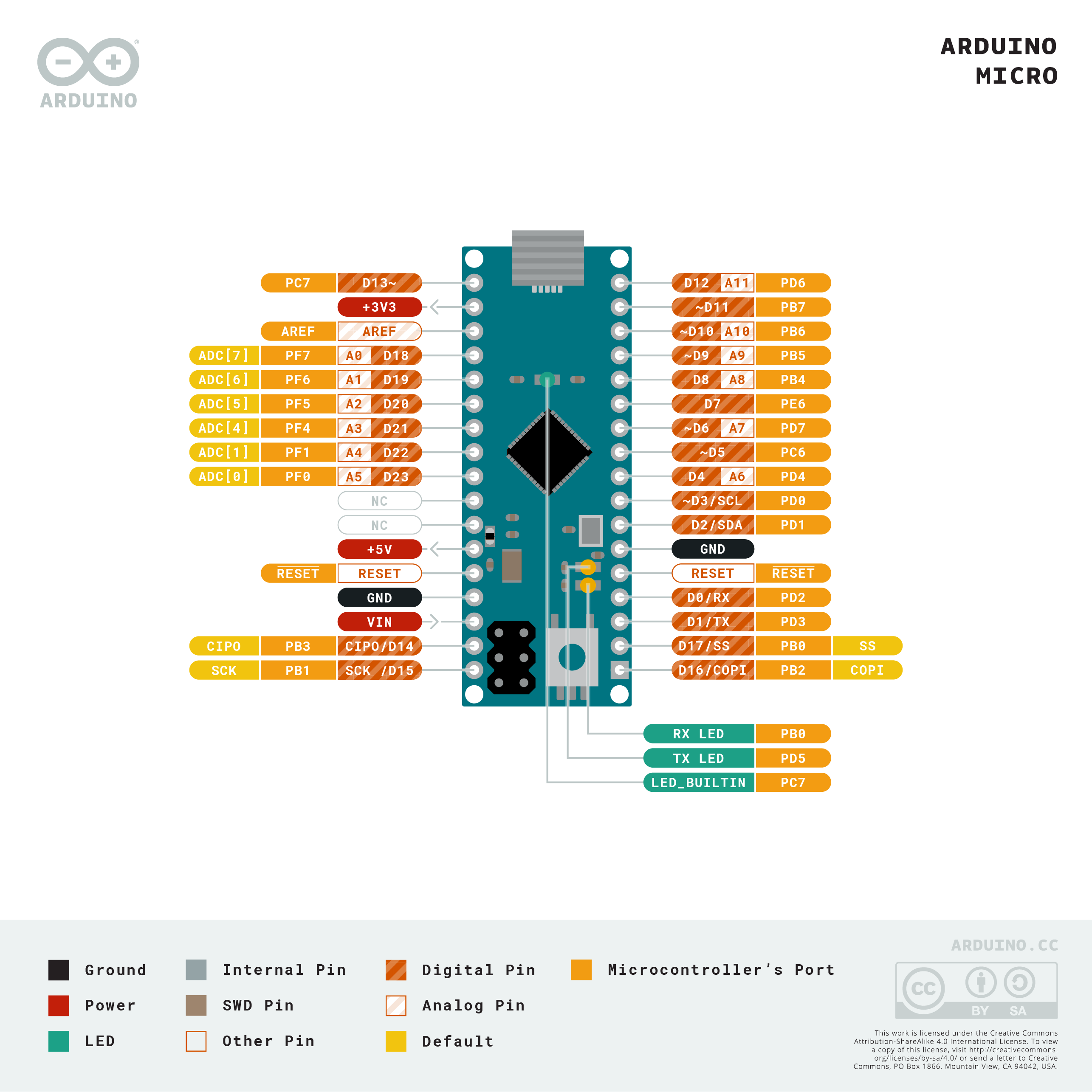
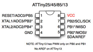 north stream
It's bedtime for me
slender steeple
oki bye
I will continue to try to figure this out I geuss

so there is a bug
they fixed it
but I gotta see how I can fix it
autumn karma
stable forge
Adafruit_TinyUSB_Arduino wraps the functionality of the core TinyUSB library for...
Thanks for the insight @stable forge! I'm guessing the TinyUSB library on it's own might require a little more lower level manipulation to use it?
thorny cedar
north stream
There are likely a few things slowing it down. It may be doing an erase/write f...
How can I encode the buffer using vectors of integers? The example below shows using a String variable.
https://github.com/arduino-libraries/SD/blob/master/examples/NonBlockingWrite/NonBlockingWrite.ino
When I code like this example, the sample rate drops considerably (from 35 ksps to 4 ksps), compared to:
...
arr[count] = analogRead(VBATPIN);
t[count] = micros()-lastMicros;
...
As for recording to SD, your tip was useful for my problem, the recording time reduced from 500ms to less than 10ms. On the other hand, as I said, the sample rate is no longer useful for my application.
In short:
Before - sampling at 35 ksps/recording 500 ms
After - sampling at 4 ksps/recording at 10 ms

GitHub
SD Library for Arduino. Contribute to arduino-libraries/SD development by creating an account on GitHub.
cerulean knoll
uh, that example is interesting because it doesn't look to me like it's doing what I'd call a "non blocking write"
it looks like it's doing a non blocking check of whether to write, and then doing a blocking write if the buffer is full
maybe I'm misreading it
If RAM constraints allow it, maybe do the write to the SD card after the full recording has been captured?
then you'd avoid slowing down the capture loop
Could be worth making sure there aren't any surprise dynamic resizes of that String buffer. Writing some kind of stack based circular buffer to use instead could be pretty straightforward
the "remove" call seems like that can't possibly be performant, but maybe it's internally implemented as a ringbuffer or something idk
(seems unlikely because I think Strings are dynamically resizable)
What's the total size of the recording?
What about
txtFile = SD.open("file.txt", FILE_WRITE);
  if (!txtFile) {
    Serial.print("error opening file.txt");
    while (1);
  }
txtFile.write(arr.data(), arr.size() * sizeof(arr[0]));
That should do a buffered, synchronous write I think? The first argument is the address of the vector's underlying storage, and the second its size
cedar mountain
Does size() return the byte size or the array length in number of elements?
cerulean knoll
number of elements I think. I was assuming a char/uint8_t buffer but that's a good thing to note
also it looks like OP wanted to interleave two buffers
But this relies on the write being in contiguous memory. Maybe instead of having a separate t and arr just store both values in alternating cells of the same array
or be ok with having two chunks of non-interleaved output?
also consider if you want the output to be binary or text based
added a mult by sizeof(arr[0]), which I assume would work
rough torrent
if your microcontroller allows it, what you can do is set up an interrupt to read it to a buffer, and in the main loop just constantly pull from the buffer and write
tribal cipher
I need help. Please guide. The gsm module is not sending sms. Im using GSM 800A module.
`#include <SoftwareSerial.h>
SoftwareSerial SIM900(7, 8);
void setup() {
SIM900.begin(19200);
// Give time to GSM shield to log on to network
delay(100000);
// AT command to set SIM900 to SMS mode
SIM900.print("AT+CMGF=1\r");
delay(1000);
systemReady();
}
void loop() {
// put your main code here, to run repeatedly:
}
void systemReady()
{
// Set recipient's mobile number in international format
SIM900.println("AT + CMGS = "+91xxxxxxxxxx"");
delay(100);
// Set SMS message
SIM900.println("System is running as expected.");
delay(100);
// End AT command with a ^Z, ASCII code 26
SIM900.println((char)26);
delay(100);
SIM900.println();
// Give module time to send SMS
delay(5000);
}`
This is my code
 little token
const float voltage = 5.00; // CHANGE THIS FOR 3.3v Arduinos
const float res = voltage / 1024;
const float resistorValue = 10000.0;
int threshold = 3;
int iP = A0;
int oP = A5;

void setup()
{
 Serial.begin(9600); // starts serial monitor
 pinMode(oP, OUTPUT); // sets output pin to OUTPUT mode
 pinMode(iP, INPUT); // sets input pin to INPUT mode
}

void loop()
{
 int analogValue = 0;
 int oldAnalogValue = 1000;
 float returnVoltage = 0.0;
 float resistance = 0.0;


 while(((oldAnalogValue-analogValue)>threshold) || (oldAnalogValue<50))
 {
 oldAnalogValue = analogValue;
 digitalWrite(oP, HIGH );
 delay(10); // allow ringing to stop
 analogValue = analogRead( iP );
 digitalWrite(oP, LOW );
 }

 Serial.print("Return voltage : " + analogValue * res + " v.");
 Serial.print("That works out to a resistance of : " + ((5.00 * resistorValue) / returnVoltage) - resistorValue + " Ω.");

 delay(5000);
}
This is the code someone sent me
and im having trouble understanding what oldanalogvalue is used for
and why the while loop condition is there, for what reason etc
this is for an arduino project to measure conductivity of a liquid
if anyone can help me
cedar mountain
The loop is basically running until the analog value settles down enough to be almost equal in two successive readings. I'm not sure why the sensor would have some initial instability, but that's what the code expects to happen.
little token

Arduino Project Hub
Learn about water quality in a fun way! Assemble your own DIY water probe and measure conductivity - the degree of pollution of any liquid. By EDUcentrum.
this is the page my friend got it from if there is any explantion you can see that i cant?
cedar mountain
No, I'm afraid not. I'm not sure why the code is pulsing the output pin either.
Possibly there's some subtlety about how ions in the water react to the voltage.
little token
can i ask what you mean by pulsing the output pin?
sorry not that informed on arduino
just enough to get it to work
cedar mountain
These lines:```digitalWrite(oP, HIGH );
digitalWrite(oP, LOW );```turn on and off the output pin each time though the loop. So I'm not quite sure why it's doing that, instead of just turning it on and leaving it on at the beginning.
stable forge
autumn karma
Thanks for the insight <@329766224093249548>! I'm guessing the TinyUSB library o...
exactly
final yacht
cedar mountain
Possibly there's some subtlety about how ions in the water react to the voltage.
Or, it could be a poorly written and might even contain errors
 west leaf
I'm struggling to figure out how to write values that persist when power is off on a Circuit Playground Express using the Arduino IDE
I would expect to use something like EEPROM, but #include "EEPROM.h" fails with no such file or directory
CircuitPython seems to have a nvm module, which I assume is available on the CPX, though I haven't tested it
and my searching hasn't found any examples or code mentioning how to access an EEPROM from Arduino code on the CPX (or other Circuit Playground boards)
does anyone have any suggestions for avenues I can explore? Thanks!
(I did just find https://forums.adafruit.com/viewtopic.php?p=760624 in my search, which is the same question, but is unanswered)
west leaf
(and from my delving into the CircuitPython CPX port, it does seem like the nvm module is supported, which gives me hope I just need a way of accessing it from C++ https://github.com/adafruit/circuitpython/blob/main/ports/atmel-samd/common-hal/microcontroller/__init__.c#L95)
thorny cedar
cerulean knoll
added a mult by sizeof(arr[0]), which I assume would work
Thanks. I'll try as you suggested with the 'write' function and with a vector with alternating cells with 't' and 'arr'. In fact, these variables need to associate with each other.
About the write size and the suggestion of writing to SD only at the end is unfeasible as I run out of RAM quickly (in 60ms - reading and buffering in the vector is happening at the maximum speed possible, ~25us) and I need to do the acquisition for a few minutes. The solution I'm looking for is basically the following:
0 - 60 ms: reading + buffering
60 - 70 ms: writing to SD (~15% data loss on each buffer flush cycle)
70 - 130....
...
I've been using the SD library. Do you think the performance would be better with SDFat?
My board is the Feather m0 adalogger. Would the microcontroller support interrupts? If yes, would you indicate any example to start understanding this? Why using interrupts would be better?
I have no experience with embedded systems or c/c++. At least I have some experience in other languages. Sorry for so many questions.
north stream
tribal cipher
`#include <SoftwareSerial.h>
SoftwareSerial SIM900(7, 8);
void setup() {
SI...
I don't think you want spaces in the command (use AT+CMGS=), and you may need to do an AT+CMGF=1 before you send the SMS
wet crystal
Hey people. I am stuck at something maybe someone else can help me out
I´m still working on the Ninebot turn indicator bord and someone send me the code to replace with, but I have no clue how to compile it 😄
thorny cedar
I keep having problems in the 'write' function of the 'File' from "SD" library. Could someone give me a very simple example of initializing a vector with alternating cells ('micros' and 'analog pin value'), and how to assign and use it in the write function? My C level is pretty low. With a variable of type String, the recording works well as in the example I mentioned, but the lines 'buffer += ....' are very slow (fast writing, but slow reading). My application is quite simple: I need to read an analog input at the highest possible rate from the void loop() and write these integers along with the time (t, v) to a file.
west leaf
west leaf
(and from my delving into the CircuitPython CPX port, it does seem like the nvm ...
For anyone searching the archives for a similar problem, I found a solution using the SPI_Flash library: https://forums.adafruit.com/viewtopic.php?p=947336#p947336
cerulean knoll
thorny cedar
Thanks. I'll try as you suggested with the 'write' function and with a vector wi...
I don't have an Arduino handy to test this out, but:
#include <SD.h>

#define NUM_ENTRIES 3000
#define BUFFER_SIZE (NUM_ENTRIES * 2)
int t_and_v[BUFFER_SIZE];

...

File f = SD.open("file.txt", FILE_WRITE);
if (!txtFile) {
  Serial.print("error opening file.txt");
  while (1);
}
for(int n = 0; n < BUFFER_SIZE; n+=2) {
  t_and_v[n] = millis();
  t_and_v[n + 1] = analogRead(ANALOG_PIN);
}
txtFile.write((char *) t_and_v, BUFFER_SIZE * sizeof(int));
Seems like it might work? The buffer here should probably be a byte buffer, but you can probably get away with this.
I am curious though, how are you reading this data? Because this is going to print binary (and be the endianness of your CPU, etc). You might actually want to use a string. If so we can find a smart and fast way to do it.
Also, just to try and understand this better, is there a reason you're trying to sample so quickly?
 safe halo
How do I get each element from an array when I don't know what the key numbers are? Such as when the 1,2 3,4,5 are 7,4,8,3,22?
    File file = SPIFFS.open("/sensors.json", FILE_READ);
    if (!file)
    {
      Serial.printf("Failed to load settings.\n");
      return;
    }
    char json[512] = "\0";
    int i = 0;
    while (file.available())
    {
      json[i] = file.read();
      i++;
    }
    StaticJsonDocument<i + 16> doc;
    DeserializationError error = deserializeJson(doc, json);
    if (error)
    {
      Serial.print("deserializeJson() failed: ");
      Serial.println(error.c_str());
      return;
    }
    for (size_t i = 0; i < 128; i++)
    {
      String sens = doc[i];
      Serial.printf("%s\n", sens);
      if (sens != "")
      {
        String t = sens.substring(0, sens.indexOf(","));

        snsr[i].selected = true;
        snsr[i].sensorType = t.toInt();
      }
This is the JSON it is loading:
{
    "1": "2,P/R",
    "2": "2,B",
    "3": "2,A",
    "4": "2,T",
    "5": "7,S"
}
Does that code you posted not work?
 odd scarab
Dose anyone have any idea why a Adafruit 2.8" TFT Touch Shield v2 will work using the examples in the Adafruit_ILI9341 library, but not on a Arduino Mega? (tried with 2 and just get a white screen with serial port saying the sketch is running).
 native sundial
Hi everyone, I am trying to find out if the Adafruit QT Py SAMD21 board has a MACRO similar to the Seeed Xiao SAMD21 board?
For example, in a library that I am using there is a define for the Xiao as follows:
// Seedstudio XIAO M0 port #if defined(SEEED_XIAO_M0)
Any help or pointers to documentation would be greatly appreciated 🙌
solemn cliff
I think it's QTPY_M0 or ADAFRUIT_QTPY_M0
 outer yarrow
I am trying to run a simple example on Pi Pico using Arduino IDE for a usb midi device using Adafruit_TinyUSB. I am able to see a USB device is detected on the PC. However, Serial.print just doesn't work. It seems there is some issue related to tinyusb library and USB serial output.
solemn cliff
native sundial
Hi everyone, I am trying to find out if the Adafruit QT Py SAMD21 board has a MA...
or both, the first one is the board build name, the second one is part of added build flags, not sure where it's documented (I searched the board definitions), but every board has one
native sundial
solemn cliff
or both, the first one is the board build name, the second one is part of added ...
Ok, thank you! That's super helpful. By searching board definitions, do you mean in the boards.txt file?
In that file I see:
# Build adafruit_qtpy_m0.build.mcu=cortex-m0plus adafruit_qtpy_m0.build.f_cpu=48000000L adafruit_qtpy_m0.build.usb_product="QT Py M0" adafruit_qtpy_m0.build.usb_manufacturer="Adafruit" adafruit_qtpy_m0.build.board=QTPY_M0 adafruit_qtpy_m0.build.core=arduino adafruit_qtpy_m0.build.extra_flags=-D__SAMD21E18A__ -DCRYSTALLESS -DADAFRUIT_QTPY_M0 -DARM_MATH_CM0PLUS {build.usb_flags} adafruit_qtpy_m0.build.ldscript=linker_scripts/gcc/flash_with_bootloader.ld adafruit_qtpy_m0.build.openocdscript=openocd_scripts/qtpy_m0.cfg adafruit_qtpy_m0.build.variant=qtpy_m0 adafruit_qtpy_m0.build.variant_system_lib= adafruit_qtpy_m0.build.vid=0x239A adafruit_qtpy_m0.build.pid=0x80CB adafruit_qtpy_m0.bootloader.tool=openocd adafruit_qtpy_m0.bootloader.file=qtpyM0/bootloader-qtpy_m0.bin
solemn cliff
yeah that would be those:
adafruit_qtpy_m0.build.board=QTPY_M0
adafruit_qtpy_m0.build.extra_flags=-D`_SAMD21E18A_ -DCRYSTALLESS -DADAFRUIT_QTPY_M0 -DARM_MATH_CM0PLUS {build.usb_flags}
north stream
odd scarab
Dose anyone have any idea why a Adafruit 2.8" TFT Touch Shield v2 will work usin...
From the product description: "Solder three jumpers and you can use it at full speed on a Leonardo or Mega as well."
north stream
outer yarrow
I am trying to run a simple example on Pi Pico using Arduino IDE for a usb midi ...
It could be that TinyUSB only supports one endpoint, it might not offer both MIDI and serial at the same time (then again, MIDI is a serial protocol). What endpoint types do you see on the host computer?
 worldly dome
Can you do serial to serial between to arduino uno r3s? To expand ports without the problems that come with a mega?
outer yarrow
@north stream on the github repo, i read "Use SerialTinyUSB name instead of Serial for serial monitor" and then it worked. Surprisingly none of the examples use this. On the example they simply use Serial.
I am a bit confused between circuitpython vs arduino for pi pico. The developer experience is so great with circuitpython, the changes become live in a few seconds. On arduino it does take more time to compile and upload. I believe arduino sketches should theoretically be faster. Any suggestions on this? How do the library ecosystem compare in these two approaches ?
cerulean knoll
worldly dome
Can you do serial to serial between to arduino uno r3s? To expand ports without ...
what are the problems that come with a mega? It's certainly possible to do serial to serial between two of any kind of microcontrollers, but it's almost certainly not going to be simpler than selecting a single part with more pins/peripherals/whatever
north stream
outer yarrow
I am a bit confused between circuitpython vs arduino for pi pico. The developer ...
The Arduino sketches can be faster and you can run them on less capable hardware. If you're doing something that requires fast or precise timing, responding to interrupts, or low-level bit manipulation, the Arduino environment can be the better choice. For getting off the ground quickly without getting bogged down in details, CircuitPython can be the way to go. I find them both useful, but in different ways.
tardy iron
compile times for Arduino sketches on a modern 32-bit microcontroller can get rather long, so that's one reason to stick with CircuitPython for prototyping, if possible
 north kelp
worldly dome
Can you do serial to serial between to arduino uno r3s? To expand ports without ...
north kelp
worldly dome
Can you do serial to serial between to arduino uno r3s? To expand ports without ...
I'd consider adding a multiplexer or GPIO expander, instead of using a second UNO.
https://www.adafruit.com/product/5346

We’ve gotten a lot of requests for a MCP23017 breakout and we’ve always sorta been like “ehh why not just use the DIP chip?” but with STEMMA QT we could see the use ...

You just found the perfect I2C sensor, and you want to wire up two or three or more of them to your Arduino when you realize "Uh oh, this chip has a fixed I2C address, and from what I ...
odd scarab
north stream
From the product description: "Solder three jumpers and you can use it at full ...
thank you! 👍
odd scarab
Any one able to help me edit a sketch to work with a different screen then intended, really out of my depth here.
pine bramble
How do u read if a specific neopixel is on or off
north stream
You can use the getPixels() method to get access to the library's internal pixel storage
outer yarrow
Is teensy 4.1 the fastest microcontroller for baremetal programming with arduino at present ? Do faster alternatives exist ?
outer yarrow
tardy iron
compile times for Arduino sketches on a modern 32-bit microcontroller can get ra...
I feel compilation/upload times are a lot better with platform.io on vs code.
cedar mountain
outer yarrow
Is teensy 4.1 the fastest microcontroller for baremetal programming with arduino...
I think the only faster option would be boards using the NXP iMX.RT 1170, which is in the same chip family as the one in the Teensy but is clocked even faster. I do not know offhand what the level of Arduino library support for that is, though.
 narrow wasp
Is VS Code still a viable way to do Arduino projects? I am trying to get it set up because I use VS Code for a ton of stuff and it would probably be easier for me to learn in that environment. However, some of these tutorials make it seems like the workarounds are not worth it and I cannot get through them without an issue.
pine bramble
narrow wasp
Is VS Code still a viable way to do Arduino projects? I am trying to get it set ...
Pretty sure there's strong advocacy for using VSCode with Arduino IDE based code. A lot of people end up with platformio as their primary dev environment. Some probably use VSCode in conjunction with it.
narrow wasp
pine bramble
Pretty sure there's strong advocacy for using VSCode with Arduino IDE based code...
Thanks! So I should just start using platformio now then huh? I've tried it but didn't really get comfy with it since I am still struggling with understanding all of my boards lol. Right now I am trying to get a Arduino Nano Connect RP2040 to do HID stuff but I am not sure this is the right board.
Oh wow, installed PlatformIO extension in VS Code, this seems robust and a bit overwhelming lol
pine bramble
I use the command line (only) but there's a platformio gui as well (have seen user screenshots askinq questions, but it was unclear what I was seeing. ;) @narrow wasp
RP2040 basically seems to devolve to pico-sdk (most dev environs leverage it to some degree) so it's worth it to at least 'try' the pico-sdk natively; earle philhower's port is usual though.
quaint nebula
I need help
New to arduino LEDs and I downloaded IDE and and I have fast led and the adafruit neopixel library in there
But it’s just not working
When I hit upload I get an error


Here’s the strips im using
 north stream
An upload error generally means the host can't communicate with the device you're programming
north stream
First, you have to find out what the problem really is. Does it see the device?
 wide shadow
I've tried both https://www.adafruit.com/product/1651 and https://www.adafruit.com/product/1947 on an Arduino Mega doing the Adafruit_ILI9341 -> graphicstest and both screens are totally white through the whole process. These devices are essentially New old stock. I bought them in 2015, put them on a shelf and never used them.

Spice up your Arduino project with a beautiful large touchscreen display shield with built in microSD card connection. This TFT display is big (2.8" diagonal) bright (4 white-LED ...

Add some sizzle to your Arduino project with a beautiful large touchscreen display shield with built in microSD card connection and a capacitive touchscreen. This TFT display is big ...
north stream
wide shadow
I've tried both https://www.adafruit.com/product/1651 and https://www.adafruit.c...
Did you install the jumpers to support the Mega?
wide shadow
What jumpers?
north stream
Just a minute, gotta jump through some hoops for no reason
wide shadow
I guess I found the jumpers. Now to get my USB ports working again on my PC
Eventually, I want to get this working on a Feather M0, but the mega will do for now.
north stream
It should be doable on a Feather if the 3.3V signalling works with it (I'm guessing it will)
wide shadow
Planning on making my own thermostat with the BME688 and control it with Home Assistant.
north stream
Heh, I was making a thermostat a while back but ended up using these triangular pushbutton switches https://www.adafruit.com/product/4189
wide shadow
Nice find. Saves me from finding some buttons with triangles stenciled on them.
livid osprey
quaint nebula
When I hit upload I get an error
Could you share with us the error you’re getting?
quaint nebula
Hang on I’m currently at work

This was from when I tried to run neopixel strand test
livid osprey
Ah, that’s a compile error. I don’t think the ZeroDMA library is compatible with a regular arduino nano. Try the non-DMA library instead.
quaint nebula
Where can I find that?
I also downloaded the arduino fast led library and that didn’t work as well
livid osprey
quaint nebula
Where can I find that?
From Tools > Manage Libraries, search for "Neopixel" and select the "Adafruit Neopixel" library as shown.

Ignore the 1.8.7 and install the latest, mine is pretty out of date.
quaint nebula
Okeh
livid osprey
quaint nebula
Already have it installed
Oh, then try removing the _ZeroDMA
 quaint nebula
Ah okeh
blazing crane
Spent a couple weeks on a project using a Nano 33 IoT. Now that I have it working, I need to make 6 more of them by Saturday (uggh).
Unfortunately, the Nano 33 IoT is out of stock everywhere...
To what extent is the Nano RP2040 Connect a drop-in replacement?
Because I don't have time to significantly alter the code or order more PCBs
 west quarry
Is there a repo of colour effect functions somewhere? Ideally documented to explain how it works
plz tag me in response 🙂
livid osprey
blazing crane
To what extent is the Nano RP2040 Connect a drop-in replacement?
Definitely not drop in, but the majority of libraries should be fairly easy to port, as most of the major libraries for samd are also available for rp2040?
blazing crane
livid osprey
Definitely not drop in, but the majority of libraries should be fairly easy to p...
Here's what I'm currently using Wire ArduCAM SPI WiFiNINA Adafruit_NeoPixel
quaint nebula
livid osprey
Oh, then try removing the _ZeroDMA
Should I also change the PIN number and number of LEDs when running the strand test?
livid osprey
blazing crane
Here's what I'm currently using ```
Wire
ArduCAM
SPI
WiFiNINA
Adafruit_NeoPixel`...
Not sure about wifinina, but the other four should not be an issue for you to my knowledge.
livid osprey
quaint nebula
Should I also change the PIN number and number of LEDs when running the strand t...
Yes, it should match whatever configuration you’re testing.
quaint nebula
still not working
quaint nebula
livid osprey
Yes, it should match whatever configuration you’re testing.
heres the message i got
C:\Users\senec\AppData\Local\Temp.arduinoIDE-unsaved20221012-24300-6s9du7.a7i2s\strandtest\strandtest.ino:8:10: fatal error: Adafruit_NeoPixel: No such file or directory
#include <Adafruit_NeoPixel>
^~~~~~~~~~~~~~~~~~~
compilation terminated.
exit status 1
Compilation error: Adafruit_NeoPixel: No such file or directory
and tried it with the _ZeroDMA
In file included from C:\Users\senec\AppData\Local\Temp.arduinoIDE-unsaved20221012-24300-1ge8vnc.hmjt\strandtest\strandtest.ino:8:0:
C:\Users\senec\OneDrive\Documents\Arduino\libraries\Adafruit_DMA_neopixel_library/Adafruit_NeoPixel_ZeroDMA.h:4:10: fatal error: Adafruit_NeoPixel.h: No such file or directory
#include <Adafruit_NeoPixel.h>
^~~~~~~~~~~~~~~~~~~~~
compilation terminated.
exit status 1
Compilation error: exit status 1
livid osprey
Wait which example are you referencing
livid osprey
quaint nebula
C:\Users\senec\AppData\Local\Temp\.arduinoIDE-unsaved20221012-24300-6s9du7.a7i2s...
For this one, make sure you don’t delete the “.h”
quaint nebula
okay
sacred ivy
not really arduino related but I have a question on this function:
void SPI1_ReadBlock(void *block, size_t blockSize) { uint8_t *data = block; while(blockSize--) { *data++ = SPI1_ExchangeByte(0); } }
If my analysis is correct, when I call this function, it reads multiple bytes on the SPI bus but I have to specify how many bytes, and then I think I have to point to an array.
Is that right?
SPI1_ExchangeByte is the preceding function that basically exchanges data
cedar mountain
Yes, that's right. The array has to have a size large enough to store the number of bytes you ask for.
quaint nebula
sigh still not working. arduino being real annoying rn
sacred ivy
cedar mountain
Yes, that's right. The array has to have a size large enough to store the number...
Thats handy. Since Im communicating with a MAX31855 I'll need 4 bytes of storage (or just two and forget the rest).
cedar mountain
If it makes your life easier, you can also pass in a pointer to another variable and read directly into a 2- or 4-byte integer, for example.
sacred ivy
Id have to figure out how to do that 😅
cedar mountain
Yep, if the gate voltage range of the FET is compatible with the Arduino, you can.
quaint nebula
As well as adress the LEDs?
cedar mountain
Is it an addressable strip? If so you probably don't even need a MOSFET, since they will usually want 12V power but regular logic levels for the data. I thought you meant a non-addressable strip where you wanted to PWM-control the 12V power to it.
quaint nebula
Wait you can also control analog rgb led strips on arduino?
cedar mountain
Yes, with a FET you can fade the colors via a PWM signal. You won't get individual pixel addressing, but you can select a general color and brightness for the whole strip.
wide shadow
I'm having trouble getting https://www.adafruit.com/product/5046 going. I'm following the learn article too. Using all defaults for I2C on an Arduino MEGA. Doing the example Adafruit BME680 Library sketch of bme680test and it can't find the sensor. I've verified the wiring. Connected up the yellow wire to pin A5 and the blue wire up to pin A4. What am I doing wrong? I was messing with the touch screen on a capacitive touch 2.8" display earlier via this same setup and it worked just fine.

The long-awaited BME688 from Bosch gives you all the environmental sensing you want in one small package. This little sensor ...
north stream
Maybe try an I2C scanner to see if anything is answering up?
wide shadow
Removed all wires from the LCD panel and no I2C devices detected with just the BME688 connected.
cerulean knoll
Any chance you have SDA and SCL swapped?
wide shadow
I'm using https://www.adafruit.com/product/4209 from the BME688 and made sure that the yellow is in A5 and Blue in A4

This 4-wire cable is a little over 150mm / 6" long and fitted with JST-SH female 4-pin connectors on one end and premium Dupont male headers on the other. Compared with the chunkier ...
I even swapped which end the sensor is plugged into and no change.
leaden walrus
try these pins instead of A4/A5
 wide shadow
YAY! I'm getting a response now from the I2C Scanner. Strange it wouldn't work on A4 and A5 when the touch screen does.
 quartz furnace
Anyone know of an Arduino library that would get the Bluetooth data from a Nintendo Switch controller? Saw these at 5 below .. they are BT 5.0 so maybe with an ESP32-S3 ?

Didn’t see much on a google search…., only saw how to make your ESP32 with connected buttons *Acting as a controller
I however want to use these slim somewhat expensive controllers
livid osprey
quartz furnace
Anyone know of an Arduino library that would get the Bluetooth data from a Ninte...
Something like https://gitlab.com/ricardoquesada/bluepad32 allows pairing with an ESP32 classic.

 trail swallow
I have a Feather M4 Express, and I stopped being able to upload my code to it despite trying to press reset as the upload starts. When I press reset, it'll turn on and blink the built-in LED for just a moment, but never seems to show up for programming. I uploaded it to another Feather M4 Express to try to rule out hardware problems and it started doing the same thing. :( Any suggestions what else to try to recover it?
trail swallow
Aha, updating the bootloader did the trick.
wide shadow
I have a BME688 sensor (https://www.adafruit.com/product/5046) hooked up to an Arduino MEGA. The Example sketch bme680test from Adafruit BME680 Library works fine, but when I try to get the basic sketch from BSEC Software Library to work, even with following the Learn guide (https://learn.adafruit.com/adafruit-bme680-humidity-temperature-barometic-pressure-voc-gas?view=all), get errors:
Arduino: 1.8.19 (Linux), Board: "Arduino Mega or Mega 2560, ATmega2560 (Mega 2560)"
Build options changed, rebuilding all
/tmp/ccSAI8GV.ltrans0.ltrans.o: In function `main':
/home/ayourk/Arduino/libraries/BSEC_Software_Library/src/bsec.cpp:155: undefined reference to `bsec_init'
/home/ayourk/Arduino/libraries/BSEC_Software_Library/src/bsec.cpp:317: undefined reference to `bsec_get_version'
/home/ayourk/Arduino/libraries/BSEC_Software_Library/src/bsec.cpp:173: undefined reference to `bsec_update_subscription'
/home/ayourk/Arduino/libraries/BSEC_Software_Library/src/bsec.cpp:200: undefined reference to `bsec_init'
/home/ayourk/Arduino/libraries/BSEC_Software_Library/src/bsec.cpp:200: undefined reference to `bsec_update_subscription'
/home/ayourk/Arduino/libraries/BSEC_Software_Library/src/bsec.cpp:214: undefined reference to `bsec_sensor_control'
/home/ayourk/Arduino/libraries/BSEC_Software_Library/src/bsec.cpp:374: undefined reference to `bsec_do_steps'
/home/ayourk/Arduino/libraries/BSEC_Software_Library/src/bsec.cpp:446: undefined reference to `bsec_get_state'
/tmp/ccSAI8GV.ltrans2.ltrans.o: In function `Bsec::setState(unsigned char*) [clone .constprop.17]':
/home/ayourk/Arduino/libraries/BSEC_Software_Library/src/bsec.cpp:282: undefined reference to `bsec_set_state'
collect2: error: ld returned 1 exit status
exit status 1
Error compiling for board Arduino Mega or Mega 2560.
I know that the Learn page says that the learn page says that Arduino Mega isn't suggested, but I'm just doing testing to move to a different board later. What am I doing wrong?
trail swallow
I see a big “Not every chipset is supported by the closed-source BSEC library!” which seems like it would explain it.
wide shadow
But the learn article does state that Mega could be used.
livid osprey
wide shadow
I have a BME688 sensor (https://www.adafruit.com/product/5046) hooked up to an A...
It does look like there are a lot of broken references, and almost entirely within the BSEC library source. Seems like some modifications to a certain “platform.txt” file is needed.
I have a (Arduino Clone) Mega 2560 Board with Seed Grove BME680 Sensor. I use Arduino CC version 1.8.12 I am running into Linker issues when compiling my sketch(es) using various libraries: 1/. Using Seed Studios Library for the sensor, I find it works OK, but lacks functionality, namely unable to p...
wide shadow
I've made the modifications to platform.txt for avr, samd, and esp32
livid osprey
wide shadow
I've made the modifications to platform.txt for avr, samd, and esp32
If you have the SAMD and ESP32 modifications in there, take them out. Should just be AVR?
Oh, nvm.
You added “compiler.libraries.ldflags=“ and you still get the same compile error?
wide shadow
Correct.
livid osprey
Is it possible you have a “platform.local.txt” somewhere that might be overriding it?
wide shadow
I checked. Nothing relevant in the appropriate paths.
I did find a few platform.local.txt files, but nothing in the ~/.arduino15 dirs or used library dirs.
When I switch to my target board (https://www.adafruit.com/product/3857), I get the following errors: https://pastebin.com/srgL38YD
And errors in verbose mode: https://pastebin.com/nB4ti8Re
Pastebin
Pastebin.com is the number one paste tool since 2002. Pastebin is a website where you can store text online for a set period of time.
Pastebin
Pastebin.com is the number one paste tool since 2002. Pastebin is a website where you can store text online for a set period of time.
hazy roost
Hello, I have a cosmic watch sensor: http://www.cosmicwatch.lns.mit.edu/ which has an arduino nano on it and id like to use UART to write sensor data to to my computer. I have a UART to USB adapter, and was wondering how I could go about connecting this so that I can record sensor data in a plain text file?
north stream
Basically, you'd connect the TX and 0V reference leads from the Nano to the asynchronous serial adapter. Then on the host computer, open the device for the serial adapter, set up any communication parameters required to match the Nano's serial configuration, then read from the adaptor and write to the file.
 hexed sphinx
Hi, has anyone succeeded to make a tilt-compensated compass with the HMC5883L or something?
north stream
You seem to have crossposted this question. Perhaps no one has done that exact thing. Do you have a specific problem you're trying to solve?
cold lagoon
Hi im trying to get a clean RGB Fade animation. I've come up with this:
https://pastebin.com/tfnQYDMN
but it seems to skip a for loop every now and then (could be that my circuit is trash but i don't hope so since those are PCB's i've ordered).
Is there a cleaner way of writing this out?
Pastebin
Pastebin.com is the number one paste tool since 2002. Pastebin is a website where you can store text online for a set period of time.
btw. the hardware works fine with an RGB Blink code.
north stream
cold lagoon
Hi im trying to get a clean RGB Fade animation. I've come up with this:
https://...
Yeah, there are a few different ways to write this. I stared at it a while and I'm not sure what the desired sequence is, but the basic idea is to have an outer "color" loop that cycles R, G, B and an inner ramping loop that counts 0-255 (and 255-0, perhaps? I'm not sure) and sends it to the appropriate channel.
cold lagoon
thats smart it would get some of those for loops out. ill try that tomorrow.
 umbral zinc
can someone help with PID speed controller? I am using potentiometer to put the target speed. But when brakes are on motor is not going back to target speed( like 600rpm difference). I am confused in finding right parameters.... I looked to Latzel method but cant get the parameters from it . https://pastebin.com/dF0AdmAY
Pastebin
Pastebin.com is the number one paste tool since 2002. Pastebin is a website where you can store text online for a set period of time.
cerulean knoll
it sounds like perhaps some integral gain would assist that?
not sure what the optimal tuning parameters would be, but an integral component will usually help eliminate average steady state error
it also might help to print some diagnostic information over the serial connection
not sure if that would slow down your loop too much though...
umbral zinc
We have the software to plot the rpm with sensor
during the brake it doesnt gain speed , it should give more output power
cerulean knoll
I guess what I'm curious to know is, does your controller think there's error under those conditions?
one possible cause would just be that something is a bit off in calculations, and the controller thinks that's the right speed
umbral zinc
yeah I am confused with the ratio of parameters , cant find right method to calculate
cerulean knoll
uh I remember doing zeigler nichols tuning in the past. It's been a long time. Sometimes it's just a matter of experimentation
umbral zinc
I wanted to try it , setting Kp at max to oscillate
umbral zinc
I am not sure , I didnt see any continuos oscillations
cerulean knoll
even at maximum gain?
umbral zinc
yeah , maybe the plotting software isnt right
cerulean knoll
and just to be sure this is with Ki and Kd at 0?
umbral zinc
I will try to connect 2 potentiometer for Kp and Ki to tune
cerulean knoll
are you able to share pics of the RPM plot?
cerulean knoll
umbral zinc
I will try to connect 2 potentiometer for Kp and Ki to tune
yeah that is a good idea
umbral zinc
I will repeat tomorrow
cerulean knoll
maybe you might want to add a reset button for the integral gain or something too
since tuning the integral gain won't (automatically) reset the integral sum to 0
I'd be interested to see plots without the brakes applied
oh hey, I would also recommend just setting Kd to zero for now
umbral zinc
yeah I am doing PI controller first
cerulean knoll
I am not a PID expert, but I think it might make sense to just do PI first
ah yeah
I just noticed there's Kd = 2 in your code, but maybe it's an old copy 🙂
umbral zinc
yeah my previous tries , was playing around with parameters
cerulean knoll
I've been working on the temperature control for my espresso machine
 umbral zinc
about the integral, so i am summing the errors for that. Never thought about reseting it. Should I ?
cerulean knoll
well, it might be helpful if you want to see how the changes to parameters affect steady state behavior
let you get rid of any accumulated overshoot
When I was tuning this espresso machine, I started by adjusting for steady state error and not considering disturbance/startup transient
as you can see, the integral component causes substantial overshoot. But it does come back down fairly quickly
I thought this video was helpful: https://www.youtube.com/watch?v=uXnDwojRb1g

For more information, see http://nu32.org. This video is a supplement to the book "Embedded Computing and Mechatronics with the PIC32 Microcontroller," Lynch, Marchuk, and Elwin. It is part of Northwestern University's ME 333 Introduction to Mechatronics.
L-comp: Explain why you have to be careful not to make the integral gain Ki too large.
 tranquil ledge
Hi! I am using a Grand Central M4 for my college actuators class and I need to control a dc motor using pin 11 for speed.
The problem is that said pin always outputs 0V when analogWrite is used but when digitalWrite is used it outputs the reference voltage even tho it says that pin 11 can be used for pwm in the documentation. Does anyone by any chance know why is this? Please
north stream
tranquil ledge
Hi! I am using a Grand Central M4 for my college actuators class and I need to c...
What's the pin mode? What value range are you using for analogWrite()?
tranquil ledge
north stream
What's the pin mode? What value range are you using for analogWrite()?
Im using pinMode OUTPUT and the value is 150
north stream
Are you using analog pin 11 or digital pin 11?
tranquil ledge
digital pin 11, but that should be a problem since in the documentation says that this pin can handle PWM, and as far as I know that is needed for using analogWrite
north stream
150 is going to be pretty low, I think the PWM range on the M4 is something like 0-19999
tranquil ledge
hmm I dont know because I have also tested the same in other digital pins that support PWM and with 255 they reach the maximum, which is 3.3V :/
oh
nevermind, I tested it with 19999 and it works
so if my code is based in a maximum of 255 to get the same results with the range of 19999 I should map it, right?
north stream
You can do that, or change the range register (I'll admit I don't know the details of how to do so, but I seem to recall that it's doable)
umbral zinc
I put Ki to 1000 and Kp to 15 today . Also , Ki / Integral sum for the PI. Set the motor speed to max at the start because it didnt want to start itself. Also added 200 to the power , I think it might be negative sometimes . @cerulean knoll


 tough pewter
helloo
im using the arduino ide to upload ros serial to an adafruit esp32 s2 feather board
everytime i upload the board performs a factory reset and deletes everything including circuit python
im starting to think its not ready to accept ros serial ?
north stream
tough pewter
everytime i upload the board performs a factory reset and deletes everything inc...
The Arduino IDE does tend to replace everything on the board, it's not really compatible with CircuitPython. You can use one or the other, and switch between them, but not both at once. I'm not familiar with ROS serial, is it an Arduino sketch, a CircuitPython program, standalone, or something else?
tough pewter
no its a library that allows the MCU to become a standalone ROS node that can publish and subscribe
the thing is, everything works well until i add the ROS serial components, then the board factory resets
tough pewter
the function nh.initNode() specifically causes the reset
north stream
I'm not familiar with that particular code base, but this page seems to say that you need to add a #define to match the hardware you're running it on, and I don't see an entry for ESP32. http://wiki.ros.org/rosserial_arduino
north stream
Ah, that's a useful data point. I wonder if the S2 is different enough that it would need a code modification to work.
tough pewter
i think i should ask the ros community too
north stream
Good idea
 astral sail
hi, i'm trying to write arduino to control a flora rgb neopixel attached to a flora board, but all of the code snippets I am finding are for different boards or written to control a different kind of led. this is my first try and I'm learning arduino from scratch coming from a python background, so I'm struggling without anything I can use to clearly imitate and then interpret.
Can anyone point me at a solid git or some more specific tutorial than the ones I found in the uberguide?
leaden walrus
there's a flora specific example here:
https://learn.adafruit.com/getting-started-with-flora/blink-onboard-neopixel
wind drift
I am trying to use this code https://github.com/labatrockwell/arduino_capactive_sensor_MPR121 for the MPR121 sensor.
It does seem to work fine - when I touch the pins it shows P:1 - when not touching P:0
In the description though it says it can work as a proximity sensor. But for me it only triggers when I am really touching the pins
GitHub
Arduino sketch that activates all touch sensors, and the proximity sensor on the MPR121 breakout board from Sparkfun. - GitHub - labatrockwell/arduino_capactive_sensor_MPR121: Arduino sketch that a...
north stream
wind drift
I am trying to use this code https://github.com/labatrockwell/arduino_capactive_...
It does point out "Proximity measurements are cumulative readings from all sensors. Therefore, all sensors must be hooked up correctly in order for this measurement to work properly."
The page has a broken link to a writeup describing it, here's a working link to the NXP application note on proximity: https://www.nxp.com/docs/en/application-note/AN3893.pdf
wind drift
meaning all of them are connected to the same surface, correct?
north stream
I don't think so, I think they just need to be connected to something, I'm guessing proximity is a group effect. Connecting them all to the same surface would probably both confuse them as well as keeping them from detecting touches from different surfaces.
wind drift
I have it connected like here at the moment

so I would have to connect each pad to a separate surface and when I hover my hand over them it should trigger?
north stream
If I understand it correctly, that should do it.
livid osprey
There is probably a bit of playing with the sensitivity thresholds for it to work properly, though.
wind drift
By the way - where in the code does it define the A4 and A5 pins?
I only see the irqpin = 2
I am trying to wire it up to an arduino pro micro
north stream
I'll admit I haven't even looked at the code but A4 and A5 are the I2C interface pins, and since I see them hooked to the SCL and SDA pins in the picture, I'm guessing they're used that way.
wind drift
Somehow didn't get it to work with the SCL SDA pins on the pro micro. Used the Arduino Uno instead for now
I wired up some wires to each pad now but still no proximity sensing for some reason
only when I touch the cable directly it triggers
north stream
Both of those are frustrating. Is there a way to adjust sensitivity like Hem suggested?
wind drift

hm I set these to 2 and 1 now

seems to trigger now a bit better
but only 1 mm or so
 hallow needle
I'm attempting to use my Trinket M0 to control an Adfruit 128x32 I2C OLED display. I'm following the instructions here: https://learn.adafruit.com/monochrome-oled-breakouts/wiring-128x32-i2c-display
When I try to up load the example sketch (after installing the Adafruit_SSD1306 and Adafruit_GFX libraries) I get some errors while compiling.
I've pared down the sketch as far as possible to determine where the error is happening, and eventually have determined it is happening in the initial #include statements.
My current sketch is:
#include <SPI.h>
#include <Wire.h>
#include <Adafruit_GFX.h>

void setup() {
}

void loop() {
}
When I attempt to compile this I get the following error:
In file included from /Users/rhammell/Documents/Arduino/libraries/Adafruit_GFX_Library/Adafruit_GFX.h:12,
                 from /private/var/folders/c3/64d1jpps1plfg4gh6p9j9ys00000gn/T/.arduinoIDE-unsaved20221017-13738-1812fiw.ss6e/sketch_nov17b/sketch_nov17b.ino:3:
/Users/rhammell/Documents/Arduino/libraries/Adafruit_BusIO/Adafruit_I2CDevice.h:10:56: error: 'Wire' was not declared in this scope; did you mean 'TwoWire'?
   10 |   Adafruit_I2CDevice(uint8_t addr, TwoWire *theWire = &Wire);
      |                                                        ^~~~
      |                                                        TwoWire
 leaden walrus
what board are you selecting in the Arduino IDE?
hallow needle
Adafruit Trink M0. Hmmm... seems to be workign now without the verification errors. I attempted reinstalling the Adafruit_GFX library and restarting the IDE. That may have been the fix? I'll keep dabbling...
blazing crane
I've tried a number of different ways to send this post request... here's what I've currently gotten:
    client.print("POST /");
    client.print(WRITE_PAGE);
    client.println(" HTTP/1.1");
    client.print("Id: ");
    client.println(id);
    client.print("state: ");
    client.println((char) color);
    client.print("Host: ");
    client.println(server);
client.println();```I've also tried:
without the "Host" lines
with "Connection: keep-alive"
Adding the fields to the end of the URI w/ "?Id=...&state=..."
Various combinations of print and println
Using GET instead of POST but still sending the fields with it
(This is WiFiNINA btw, and I have access to the server and have been monitoring the requests with Wireshark)
blazing crane
fixed it
cold lagoon
Can i connect something the pins 0 and 1 on an arduino leonardo, without worrying that i cant upload code anymore (cause its the RX and TX pins). I think i had some trouble view years ago when i connected something to an arduino uno's RX/TX pins.
I just need to connect an button with an 10k pullup resistor so nothing that would interfear wit data transfer (i think)
north stream
cold lagoon
Can i connect something the pins 0 and 1 on an arduino leonardo, without worryin...
The button is no problem if it's not pressed. The 10k pullup will tend to fight with the 1k coupling resistors to the serial adapter, forming a voltage divider. It will probably work fine, but if not, you might have to get creative.
cold lagoon
worked fine
wide shadow
I'm in a bit of a conundrum here. I have a Feather M0 WiFi (https://www.adafruit.com/product/3061) that I'm trying to get both a W5500 ethernet module (https://www.adafruit.com/product/3201) to work and a 2.8" TFT Cap touch LCD (https://www.adafruit.com/product/2090). The problem is, both of them want to use Pin 10 for CS. I'm running out of ideas on where I can move the TFT CS pin to.
I've tried pin D6 and D13; neither of them want to work there.
north stream
wide shadow
I've tried pin D6 and D13; neither of them want to work there.
You can change the CS pin, but you have to do so in two places, on the hardware and in the software, so they match. D13 can sometimes cause issues because it has an LED connected to it.
wide shadow
I've adjusted the source code to handle it, and moved it to D13 physically, but not sure what else I'm missing.
north stream
Did you cut the CS jumper?
wide shadow
not sure where that is. For the LCD, right?
north stream
https://learn.adafruit.com/assets/34323 Here's the jumper on the Ethernet board
wide shadow
Oh. So move the ethernet CS vs the TFT CS 😦
north stream
Either should work. The TFT is a breakout board so you have to wire up the CS pin anyway, so that might be the easier one to change (the board supports a few different functions, so there are multiple CS pins to deal with)
wide shadow
Yeah, moving the TFT CS is what I would prefer.
Then the config also makes it compatible for https://hackaday.io/project/168356-poe-featherwing
wide shadow
What's the easiest way to show all of the #defines?
pine bramble
@wide shadow what operating system?
wide shadow
Ubuntu Linux 22.04
pine bramble
$ egrep -R \#define
that's recursive though
wide shadow
Ok, maybe I should have specified compile time #defines.
pine bramble
All that's doing is showing only the lines that have #define in them.
$ egrep -R \#define | cat -n | less
I use 'ag' now so I don't use that syntax - can't remember the easy way to show a more limited case.
wide shadow
I'm planning on making this project capable of being used by 3 different boards: Arduino Mega 2560, Adafruit Feather M0 WiFi, and Adafruit Feather M4 Express.
Trying to get the #defines related to this and it is being difficult.
Something like ```
#if defined(AVR_ATmega2560)
const String] curBoard = "Arduino MEGA 2560";
#elseif defined(ADAFRUIT_FEATHER_M0) || defined(ARDUINO_SAMD_ZERO)
const String curBoard = "Adafruit Feather M0";
#elseif defined(ADAFRUIT_FEATHER_M4_EXPRESS)
const String curBoard = "Adafruit Feather M4";
#else
const String curBoard = "Unknown board";
#endif
When I select the Feather M0, it comes up as Unknown Board.
pine bramble
$ egrep -R "\#define|\#ifdef|\#endif|\#ifndef|\#undef" * | cat -n | less
There's I think an -a <number> and a -b <number> switch for egrep
wide shadow
If I can find out what the "proper" #defined tags are for the appropriate boards, then I'd be set. I did examine the different boards.txt files, but haven't found what I need yet.
pine bramble
so those defines are not in your source code they are in the board support package iirc.
boards.txt is one place to look, sure.
wide shadow
Right, which is why I'd like to have a list of the #defines that happen at compile time so I can pick and choose from that.
pine bramble
This is fairly disorganized but it's basically got good stuff in it:
https://github.com/wa1tnr/ainsuForth-gen-exp-m4/blob/main/src/compatibility.h
I tried to use it to compile differently for different SAMD21 and SAMD51 targets.
pine bramble
wide shadow
Right, which is why I'd like to have a list of the #defines that happen at compi...
I use the compiler's output itself to identify what flags are being used. Then I look for unique flags that only apply to the situation I'm in.
you can use a '#warning my warning text' in your own source to tell you exactly when that code got parsed. I use that to make sure I don't see the same warning twice. ;)
wide shadow
I've been trying. So far all of my google searches have been coming up dry with nonfunctional suggestions
YAY! That can help too, #warning.
pine bramble
You can even put them in 'factory' distributed libraries to tell you when they are included. ;)
I use the '#warning mywarning' construct because I don't want to look things up or ask questions. ;) haha
Pretty much an empirical approach, using the compiler itself as the feedback.
wide shadow
I was wondering about that. Didn't think there was something like #printf.
pine bramble
There may be another mechanism but my memory is weak on it. I know too many languages too thinly so they all get mixed up in what I remember. ;)
wide shadow
I've learned a lot of langs too, so I kind of know what you mean.
pine bramble
You can also deliberately misspell a word to get the compiler to halt and throw an error, to differentiate the code you thought you were compiling .. from the code that you are .. compiling.
That's a very quick way to check if you are on the copy of the copy of the copy or what. ;)
wide shadow
I've done that earlier today.
pine bramble
fwiw I'm finding wokwi.com helpful for rapid iteration of testing code changes, when it's working for me (when wokwi supports what I'm testing).
My hardware is super slow and outdated, so tests can take a while to compile.
wide shadow
I remember having to edit Makefiles to dump out the build environment to look through all of the different #defines in the past. Looks like with Arduino. that is tougher.
pine bramble
Well there's platformio which gives more of a familiar experience to users of Makefiles.
The Arduino IDE is more for beginners, in some regards. I mostly use it to follow along in the very same context, when helping someone else.
wide shadow
I do have code installed. Just haven't used it instead of the Arduino IDE
pine bramble
That might be a pro dev environment (I stick to stuff Debian will distribute for the most part. ;)
Should probably help you if this is going to be a career.
wide shadow
hobbyist
pine bramble
The other strong appeal of the Arduino IDE based system is all the libraries. Most vendors like Adafruit write a decent Arduino IDE compatible library for their hardware boards (breakouts).
wide shadow
Yeah, I'm going to give code a go and see if it can get all of the libs.
and I use a TON of Adafruit libs.
pine bramble
;)
I buy adafruit parts a lot because I understand how to find where they are documented. You get a lib and example code and a schematic. ;) And relevant datasheets are linked too.
wide shadow
And I'm almost all of the way done with building my own Thermostat that can be controlled over the LAN
pine bramble
I use a TMP36 based project to keep an eye on the window air conditioner's cycle state (compressor on or off). And I keep a 24 minute history (3 minutes per RGB x 8 RGB's).
red hot .. blue cold .. green transitioning
wide shadow
I also want to integrate this thermostat into home Assistant. I've been told MQTT is the way to go.
pine bramble
You sound like you can learn this. ;)
wide shadow
And I'm using similar colors in my Thermostat for the temp value. Thermostat is stuck at 2 digits for the temps, so >99 degrees = red, < -99 = blue, etc.
pine bramble
all I'm trying to do is answer one question: how many minutes is each half cycle active for? I walk into the room, and if I see all blue, I reset it and go away for 45 minutes. ;) If I see red and blue alternating (usually in groups of 2 or 3) I know it's almost time to shut it down for a few hours, or for the rest of the evening.
If I see too many greens I check the lousy wiring job I did for intermittents. ;)
wide shadow
Sounds like if you set up something like MQTT with home assistant, you'd be able to get alerts without being physically present.
pine bramble
I had it talking to If this then that but it kept failing me. this air conditioner has built in wifi whatchamacallit. I had it working great, then on its own it stopped. I don't like doing the same job twice because someone's vended tech failed.
wide shadow
This is partly why I want to make my own thermostat: I control the code behind it.
Have you set up PlatformIO before?
pine bramble
Yeah I use platformio a lot. The install may be non-trivial but reuse of existing code is easy.
Never once touched their GUI .. I use the command line (it's python driven iirc).
wide shadow
Ok, so I have Code opened up and have the .Ino file opened in it. How do I activate it?
pine bramble
I haven't worked in that environment.
Control R recompiles in the Arduino IDE.
Control U uploads the firmware you compiled to the target. In the Arduino IDE.
The usual linux/unix term is probably 'keybindings' for a quick search of what you can do with the keyboard (rather than the mouse).
wide shadow
Then in what environ have you used PlatformIO?
pine bramble
I just cd in a regular xterm and run platformio commands.
 $ source .profile__platformio
 $ cd there
 $ pio run -t upload
 $ cat ~/.profile__platformio
PATH="$HOME/.platformio/penv/bin:$PATH"
 $ cd .platformio/penv/bin/
 $ file pio
pio: Python script, ASCII text executable
Have an interesting question about a FeatherWing for Ethernet
I had gotten this board years ago

This three-in-one Particle Ethernet Feather is a mix of our Ethernet 'wing and the Tripler 'wing. The form-factor is based around the Adafruit FeatherWing Tripler. The two side ...
It asks for a MAC address…. No idea what I did with that information if it was documented for me
I got it working with a MAC address from another board I knew the address on…. Will it matter a great deal if I just make up one ? Like change the last number -/+ a few digits ?
Of note : I pigged it in my router to see if it would show the Max address in the details …. But it will just show up with what ever number I put in my Arduino code …… thoughts on any other way to get the details of the actual MAC address?
safe shell
@quartz furnace I don't believe these boards have an embedded MAC address, you can make one up
quartz furnace
safe shell
<@492123433220571166> I don't believe these boards have an embedded MAC address,...
Ahhhhh very cool … Thanks!!!
I’ll keep it all the same except for the very last part .. I know the beginning has like the vendor ID .. etc … I’d guess that would help avoid a problem down the road… but I know it’s many trillions in possibilities for a matching address
safe shell
Yeah odds are you'd never collide. If you want to guarantee you don't overlap the vendor space, you could set the lower nibble of the highest byte to 2, 6, A, or E to make it a local MAC.
north stream
quartz furnace
I’ll keep it all the same except for the very last part .. I know the beginning...
For most cases that's true, and since you can change it if you need to, it's not something to worry about. However, in big data centers, MAC address collisions are more common than it might seem. For one thing they have thousands of units from the same manufacturer (Juniper, Cisco, whatever) on the same network, and it's an instance of the "birthday paradox" where having any MAC match any other increases the probability dramatically.