#help-with-arduino
1 messages · Page 1 of 1 (latest)
 north stream
 stable forge
can you load programs onto it using Arduino? I would also try it on another computer (maybe not a Mac) to see if a BOOT drive shows up there.
You can install the UF2 bootloader using Arduino. Use plain M0 update-bootloader .ino sketch from https://github.com/adafruit/uf2-samdx1/releases/tag/v3.14.0. But try on another computer first, to make sure it's not an issue with the Mac.
 fallow valve
I haven't figure out from any of the videos on youtube about joining two ardiunos to send code to each other most covered sending code to only one I need both to talk to each other they keep sending code until I press a gateron (Cherry MX Clones) switch to input a key
fallow valve
Here's my plan for the two pro micros each one must send their own code to the another

 runic quarry
stable forge
can you load programs onto it using Arduino? I would also try it on another comp...
runic quarry
stable forge
can you load programs onto it using Arduino? I would also try it on another comp...
My other UF2 Featerhs mount just fine. Thanks for pointing out the sketch, I’ll do that.
 opal iris
Hi, i am trying to wirelessly connect two LoRa(transmitter and receiver) which is connected to arduino uno. Sender is working, but receiver is not working. What may be the problem?
LoRa board - sx1278 (433MHz)

`#include <LoRa.h>
void setup() {
Serial.begin(9600);
while (!Serial);
Serial.println("LoRa Receiver");
if (!LoRa.begin(915E6)) {
Serial.println("Starting LoRa failed!");
while (1);
}
}
void loop() {
// try to parse packet
int packetSize = LoRa.parsePacket();
if (packetSize) {
// received a packet
Serial.print("Received packet '");
// read packet
while (LoRa.available()) {
Serial.print((char)LoRa.read());
}
// print RSSI of packet
Serial.print("' with RSSI ");
Serial.println(LoRa.packetRssi());
}
}
`
This is receiver side code
I have changed frequency to 433E6 from 915E6
fallow valve
I forgot the 5th Column XD so I've put it on the right micro
since it's on the right micro....how I can make to tell the first one hey I have your 5th Column in my code input a key press event?
 smoky glacier
Hey there, i have a Adafruit ESP32-S3 Feather with 4MB Flash 2MB PSRAM - STEMMA QT / Qwiic, and i flashed it wrong as Adafruit ESP32-S3 Feather with TFT, since then it start in DEV mode over Com6. Does someone know where i can get factory reset .bin file?
 solemn cliff
smoky glacier
Hey there, i have a Adafruit ESP32-S3 Feather with 4MB Flash 2MB PSRAM - STEMMA ...
solemn cliff
smoky glacier
Hey there, i have a Adafruit ESP32-S3 Feather with 4MB Flash 2MB PSRAM - STEMMA ...
you can flash it again with the correct target after putting it in ROM bootloader mode by pressing reset while holding boot, that should work.
I do see that there is no factory reset page in the S3 guide, it will probably be added later, you can send feedback with the link on the left side of the guide.
smoky glacier
solemn cliff
I do see that there is no factory reset page in the S3 guide, it will probably b...
so it is starting in rom boot, double reset doesnt work anymore, if iam trying to select S3-2MB PSRAM its shows me an error message. In file included from c:\users\communistcat\documents\arduinodata\packages\esp32\tools\xtensa-esp32s3-elf-gcc\gcc8_4_0-esp-2021r2-patch3\xtensa-esp32s3-elf\sys-include\sys\reent.h:503,
from C:\Users\CommunistCat\Documents\ArduinoData\packages\esp32\hardware\esp32\2.0.4/tools/sdk/esp32s3/include/newlib/platform_include/sys/reent.h:17,
from c:\users\communistcat\documents\arduinodata\packages\esp32\tools\xtensa-esp32s3-elf-gcc\gcc8_4_0-esp-2021r2-patch3\xtensa-esp32s3-elf\sys-include\stdio.h:60,
from C:\Users\CommunistCat\Documents\ArduinoData\packages\esp32\hardware\esp32\2.0.4\cores\esp32/Arduino.h:27,
from C:\Users\COMMUN~1\AppData\Local\Temp\arduino_build_235989\sketch\HelloServer.ino.cpp:1:
C:\Users\CommunistCat\Documents\ArduinoData\packages\esp32\hardware\esp32\2.0.4/tools/sdk/esp32s3/include/newlib/platform_include/assert.h:20:10: fatal error: sdkconfig.h: No such file or directory
#include <sdkconfig.h>
^~~~~~~~~~~~~
compilation terminated.
exit status 1
Error compiling for board Adafruit Feather ESP32-S3 2MB PSRAM.
solemn cliff
ah so it doesn't compile even. I think I have seen that before ? Hmmmm I don't know, I would see if there's an update to the Espressif board support or maybe reinstall it
smoky glacier
solemn cliff
ah so it doesn't compile even. I think I have seen that before ? Hmmmm I don't k...
yes was using the prefernce of S2 cause i was working last on it :D, but its even stated in the document that it is broken for s3 and i need to download it from espressif thx, buddy =).
solemn cliff
ah yes, that's mentioned in the guide, I forgot about that actually 🤦
 vocal quarry
Hey all, has anyone had any luck compiling the arduino oled library (ssd1306) for the RP2040? I was able to compile the library for the uno no problem but I'm getting a bunch of iso C++17 errors when I try to compile for the rp2040.
 radiant vapor
how do I get my feather esp32 into download mode?
A fatal error occurred: Failed to connect to ESP32: Wrong boot mode detected (0x13)! The chip needs to be in download mode. For troubleshooting steps visit: https://docs.espressif.com/projects/esptool/en/latest/troubleshooting.html
 median mica
My project works, except my stepper motors run forward one revolution, then backward one revolution, once at the beginning of the sketch. I've included my code. It's not well written code, I know it needs revision, but can anyone help me figure out where I'm going wrong as far as the forward/backward once at startup? My intent is to have the steppers move forward one revolution when the button is pressed once, then backward when the same button is pressed again. Otherwise the steppers should be not moving and disabled. I am powering the steppers from a 9VDC wall wort.
the code was to long so it is attcahed as a file.
solemn cliff
radiant vapor
`A fatal error occurred: Failed to connect to ESP32: Wrong boot mode detected (0...
what board did you select ?
median mica
I figured it out. I was using an esp-01 as the button input (buttonPin) to an arduino nano. The esp-01 pin I used was also the TX pin, So when I was using the esp-01 to start wifi communication I was toggling that pin, which caused the steppers to move on startup. Sometimes, I just have to say "DUH", and slow down.
runic quarry
stable forge
can you load programs onto it using Arduino? I would also try it on another comp...
That worked, and now FEATHERBOOT shows up on the desktop. Thanks!
 agile kayak
does anyone know of a way to read audio from a 3.5mm audio cable into some kind of arduino controller?
north stream
Audio is an analog signal, so if the levels are compatible, you can connect it to an analog input pin and read it that way. In many cases, the level will need to be adapted somehow. Note that many Arduinos are not fast enough to digitize audio at full speed, so you may need a different CPU or converter depending on what you intend to do with the audio.
stable forge
runic quarry
That worked, and now FEATHERBOOT shows up on the desktop. Thanks!
Great!
 queen gale
Hello 
I have a problem, I don't understand why the display of my panel is like that?
I use :
- P3 panel / 192x96mm (SMD2121)
- Wemos D1 R32
- Adafruit RGB Matrix Shield
north stream
Looks like a pinout or configuration problem. There are some jumpers on the board that have to match the panel addressing, the ribbon cable has to be the right way around, and the software has to match the panel size, addressing, and interlace configuration.
queen gale
Do you think I should try to change my data cable?
Because this is the one that came with it .
north stream
The cable is probably fine then
runic quarry
Huh. I've been iterating on my Feather M0 arduino code, and halfway through flashing it it got stuck. I saw it was slowly pulsing red, I pressed reset once, the IDE reported the error, I tried again. Now the port doesn't show up at all, although I can still get it into UF2 mode and that mounts. But I can't seem to flash arduino code.
runic quarry
runic quarry
Huh. I've been iterating on my Feather M0 arduino code, and halfway through flas...
re-flashing the bootloader seems to have fixed that. Weird.
 worn palm
Hello PepeSipSpin
 pine bramble
Hello, i had an question. how to activate autoreset for CP2102N ( https://www.adafruit.com/product/5335 ) programmer? i have to press reset button manual while uploading a sketch.... 😦

Long gone are the days of parallel ports and serial ports. Now the USB port reigns supreme! But USB is hard, and you just want to transfer your every-day serial data from a microcontroller ...
pine bramble
i dont have any idea (this is the factory settings)

I hate such complicated tasks, why can't something work just once. I buy a product to be able to use it directly and not to worry about problems with it for days, please help (it's just that I don't have to press the reset button on the arduino every time) where can I do that with set the autoreset?
even the tx & rx leds dont work
pine bramble
pine bramble
I hate such complicated tasks, why can't something work just once. I buy a produ...
I use CP2104 (earlier chip) all the time.
It's only used flash firmware if the board's manufacturer put it on that target board (I don't use it that way; I don't have any targets that use avrdude with CP2104).
My guess is you will have to press RESET, or contact the target at 1200 bps.
pine bramble
usually i can choose the baud rate as i like and don't press a reset button because the arduino is reseted via the dtr pin. I just don't know how to activate this autoreset function...
north stream
pine bramble
Hello, i had an question. how to activate autoreset for CP2102N ( https://www.ad...
There are two signals commonly used for automatic reset with Arduino: DTR and RTS. The CP2012 board has RTS wired to that position. I think the Arduino IDE is configured to send the reset pulse to both signals but if it isn't, you would need to configure it to do so. Additionally, this board produces 3.3V signals and it is possible that is not enough voltage to provide a strong enough reset pulse for some 5V Arduinos.
pine bramble
Just strange that I have this problem with every programmer, they are different and this situation keeps coming up. as soon as i use an arduino with a built-in usb interface (same arduino type), everything works perfectly
north stream
You can, of course, look at the reset wiring on the boards with a built-in USB interface. Not much to it really, a capacitor to act as a level shifting pulse shaper. Without an oscilloscope, it's hard to know what the problem is with the external USB adapters. My current guess is they're 3.3V adapters and the voltage they provide isn't sufficient to get a strong reset pulse through the capacitor. There are 5V (and configurable) adapters available, or you could try breadboarding a level shifter to see if that's the problem.
 pine bramble
mine is 5v
pine bramble
pine bramble
i dont have any idea (this is the factory settings)
and its configurable...
i just want to enable autoreset on the programmer
Product description:
We also updated this breakout from our CP2104 Friend so that it now has USB C instead of Micro B. Otherwise it's "drop in compatible" and will work anywhere you use the CP2104 to upload firmware to microcontrollers.
It is a high quality CP2102N USB serial chip capable of uploading code at 3Mbit/s, enabling rapid development. It also features auto-reset for Arduino/ATmega328 boards, so you don't have to mess with pins and hit reset buttons. The CP2102N has better driver support than the CH340 and can handle very high speeds and variable speeds with no stability issues. Compared to the FT232RL and FT231X, the CP2102N has the same or even better capabilities - and at a great price! It even has RX/TX LEDs to help you debug your data: they blink when the chip is receiving or transmitting data.
By default we have set it to match our FTDI cables. The 6th pin is RTS, the power line is +5V and the signal levels are 3.3V (they are 5V compatible and should work in most 3.3V and 5V signal systems). Works great with any Arduino, ESP8266, ESP32, or other microcontroller that uses an "FTDI port" for communication and upload. You can also buy a 6-pin extension cable from us, which you can use to rearrange the order of the cables.
You can also find a complete collection of all modem control pins on the page in case you need the DTR, RI, DSR, etc. pins.
The item comes with a fully assembled and tested circuit board. You will receive a right angle female header and some pin headers. You can solder in the female header on the edge to make it "FTDI-like" or solder in the pin headers to plug into a breadboard and gain access to all pins.
...................Auto reset where are you?
north stream
When you say "mine is 5v", do you mean your microcontroller board or your USB-serial adapter? The product description you quoted says "the signal levels are 3.3V", which means the USB-serial adapter is 3.3V logic. You ask "Auto reset where are you?", and as I pointed out, the auto reset pin for that board is RTS.
pine bramble
the arduino is based on 5v but it doesn't work with a 3.3v arduino either... RTS may be the auto reset pin, but it doesn't do anything
if i connect the reset pin of the arduino to the DSR pin and upload a sketch (while pressing the reset button) i can upload sketches. (Only then) but I don't want to have to keep pressing reset
so it can't be the voltage (the reset pin on the arduino is actually pulled to LOW) ...
north stream
That's why I said " I think the Arduino IDE is configured to send the reset pulse to both signals but if it isn't, you would need to configure it to do so."
north stream
It's pulled to low weirdly by the capacitor. First the interface drives the signal high (3.3V) and the capacitor discharges through the reset pin protection diode. Then it drives the signal back low, and the capacitor pulls it down 3.3V from 5V (so it goes from 5V to 1.7V or so, not really 0V)
The auto-reset circuit is a decidedly weird design.
pine bramble
what can i do about it now? I don't have any components at home that I can solder and I don't really like soldering (since they are actually plug and play boards)
north stream
You could breadboard it if you had the right chips. Or you could try telling Arduino to use RTS instead of DTR. I think that is done in the avrdude.conf file by setting Reset = RTS but I don't know the details.
pine bramble
nope cant set it there
north stream
You said "so it can't be the voltage" but you also said "while pressing the reset button" so I'm not sure that's right.
pine bramble
look at that
I use avrdude at the command line when I get curious about it.
avrispmkii.program.extra_params=-Pusb
?
its the same line as in my programmers.txt
same text
pine bramble
it's a wild guess.
You would change that line in some manner, to pass params onto avrdude. I'd guess. I do not know.
 elfin thorn
Hi y'all! Can anyone point me to an example for the Adafruit Clue to activate the buzzer for beeps and such? I've looked everywhere, but come up with nothing. Thanks!
stable forge
elfin thorn
Hi y'all! Can anyone point me to an example for the Adafruit Clue to activate th...
https://learn.adafruit.com/no-touch-hand-wash-timer-for-cpx-and-clue/clue-hand-wash-timer. You use PWMOut to make it buzz. Here is a more thorough discussion of PWMOut, with buzzer examples: https://learn.adafruit.com/circuitpython-essentials/circuitpython-pwm
elfin thorn
Thanks... Though I'm looking for Arduino code.
stable forge
oh, sorry!
elfin thorn
No worries... It got me a few times when I searched. 😀
stable forge
well, you can use AnalogWrite() to do PWM to the speaker pin
there is tone() function you can use
elfin thorn
Oh, cool! Did not know that! Thanks! That help greatly!
pine bramble
elfin thorn
Perfect... Thanks!!
 quartz furnace
Have a question about the PyBadge
is it possible to make a "buzzer" sound with the board? I see it has one pin to enable the speaker and another pin that runs the buzzer. The online documents show the port of the speaker, but I am not understanding what pin toggles on the power to the speaker. Additionally, I am trying to do it without the "Arcada" library
 inland gorge
quartz furnace
is it possible to make a "buzzer" sound with the board? I see it has one pin t...
inland gorge
quartz furnace
is it possible to make a "buzzer" sound with the board? I see it has one pin t...
The Learn Guide for the PyBadge has a lot of good stuff about that : https://learn.adafruit.com/adafruit-pybadge/arduino-test Oh sorry you said no Arcada.
stable forge
quartz furnace
is it possible to make a "buzzer" sound with the board? I see it has one pin t...
The speaker is connected via an audio amplifier to pin A0. You can use that pin with the on-chip DAC, or you could use tone() and drive the speaker with a PWM signal. speaker-enable is on PA27, and is active low (pull low to enable the amplifier). I'm figuring out which pin PA27 is
quartz furnace
Hmm if it is the same on the PyGamer PA27 is pin 51
stable forge
pin D51, yes, from variant.cpp:
  // D51 Speaker enable
  { PORTA, 27, PIO_DIGITAL, PIN_ATTR_NONE, No_ADC_Channel, NOT_ON_PWM, NOT_ON_TIMER, EXTERNAL_INT_NONE },
we have a pinout diagram in the works but it's not done yet
quartz furnace
cool so SetUp code digital write pin 51 low and use A0 as the tone() assigment
inland gorge
correct
quartz furnace
and pinMode would be output since its providing power and not reading etc
inland gorge
oh actually I think digitalWrite(51, HIGH) to enable the speaker. and yeah digitalWrite() auto-changes pin to output
stable forge
right, maybe active-high, not active low as I saidbecause the schematic shows /SD (speaker DISABLE is low)
quartz furnace
That makes sense so that its not on by default and sending power to someting not working!
not being used**
And that was it!! The pin is 51, and needed to be HIGH
It is working, cool! Thanks
 low verge
My first inverter. Thank you for your helps and advices


 quartz furnace
I have a I2C question, I am using a Adafruit ESP32-S2 TFT Feather with a qwicc (I2C) connector and wish to use it with a product from DF Robot, the small problem is DF Robot had the two I2C pins swapped. Do you just declare the pin assigment before it begins? And any draw back from swapping pins? slower? chance of error? lock up? etc?
 gilded gazelle
I am trying to read a sht40 but only get zeros for temp&humidity
what am I doing wrong?
https://pastebin.com/CuZCJLwk
Pastebin
Pastebin.com is the number one paste tool since 2002. Pastebin is a website where you can store text online for a set period of time.
it is found, but thats it
quartz furnace
oops wrong message
quartz furnace
quartz furnace
I have a I2C question, I am using a Adafruit ESP32-S2 TFT Feather with a qwicc ...
If anyone has knowledge of this can you @ me. Please. I am going to step away for a few
gilded gazelle
 leaden walrus
<https://learn.adafruit.com/scanning-i2c-addresses/overview>
leaden walrus
<https://learn.adafruit.com/scanning-i2c-addresses/overview>
all the pre-checks in the setup pass
the sht40 in inbetween the clue and the si7021
7021 is fine
leaden walrus
what all addresses showed up in the I2C scan?
the SHT40 and the onboard SHT30 may have the same address:
https://learn.adafruit.com/adafruit-clue/pinouts#step-3054930
both are 0x44
gilded gazelle
Scanning...
I2C device found at address 0x1C !
I2C device found at address 0x39 !
I2C device found at address 0x40 !
I2C device found at address 0x44 !
I2C device found at address 0x6A !
I2C device found at address 0x77 !
done
30 is fine
30 is the builtin on the clue, not the breakout
leaden walrus
they both have the same address though. so it's an address conflict issue.
gilded gazelle
ok
 spice sparrow
Anyone know how to convert byte to string/ASCII?
 unique aurora
Hi All,
Just watched this video https://www.youtube.com/watch?v=5mzlP_6rZ7w, does anyone know how to do this? i cant find any documentation on what to do to achieve the same results

We re-spun our STEMMA Friend design from a SAMD21 to an RP2040 to take advantage of the more-powerful chip, to make it CircuitPython-friendlier and faster at doing stuff like I2C sniffing. While porting over the Arduino code (which pretty much works just fine) we noticed the display is a little sluggish due to SPI data being sent over one byte a...
north stream
quartz furnace
I have a I2C question, I am using a Adafruit ESP32-S2 TFT Feather with a qwicc ...
That depends on if you're using hardware I2C (which often does not support pin swapping)
north stream
spice sparrow
Anyone know how to convert byte to string/ASCII?
If the bytes are already ASCII, you can cast them from the byte (unsigned char) type to char so they're treated as a string (add a terminating null to end the string if one is not already present).
 rich coral
OK, found it, it's defined as A6
It's a shame Feather boards do not have 5V boost like MKR
north stream
They're pretty much a 3.3V ecosystem, but there are 5V boosters available separately
rich coral
north stream
They're pretty much a 3.3V ecosystem, but there are 5V boosters available separa...
booster boards are bulky (mostly because of the connectors), is there a Feather wing with boost ?
north stream
They don't have to be bulky: https://www.pololu.com/product/2564

This tiny (0.35″×0.45″) U1V10F5 switching step-up (or boost) voltage regulator efficiently generates 5 V from input voltages as low as 0.5 V. Unlike most boost regulators, the U1V10F5 automatically switches to a linear down-regulation mode when the input voltage exceeds the output. The pins have a 0.1″ spacing, making this board compatible wit...
rich coral
I'd use a 3-pin SIP sealed module, but theses are too simple, no UVLO or on/off control
quartz furnace
north stream
That depends on if you're using hardware I2C (which often does not support pin s...
Thanks, It would be default I2C hardware pins. darn.
pine bramble
Hey There, i made an own PCBA with an ATmega88PA and now i would like to upload an optiboot bootloader for it, so i can programm it via USB with the Arduino IDE.
I know, that this Chip is not used in the Arduino World and it is nothing official, but i just wanted to try it out for fun 😄
But now i have problems to upload an Bootloader to it.
I have found this Git Repo: https://github.com/sleemanj/optiboot
Added the .json file to Arduino and installed the Boards.
Now my problem is, that i have no Arduino Uno as an Arduino as ISP programmer, all i have is an Arduino Mega.
If i now try to burn the Bootloader it says stk500_recv(): programmer is not responding and so on.
If i just try to build an empty arduino project for the Atmega88PA, in my temporary directory i get an Arduino Directory with "Sketch_xxxx_with_bootloader.hex".
If i try to upload this .hex file to the Atmega88PA via Atmel-Studio and AVR-ISP-MkII it does not work either. After this i am not able to flash an new sketch to the Atmega88PA via USB.
Don´t think the Hardware has a fault, since i can compile a serial.print sketch and flash it over via Atmel Studio and it shows me data via serial monitor.
Anyone has an advice how to get it to run? 😄
GitHub
Small and Fast Bootloader for Arduino and other Atmel AVR chips - GitHub - sleemanj/optiboot: Small and Fast Bootloader for Arduino and other Atmel AVR chips
north stream
pine bramble
Hey There, i made an own PCBA with an ATmega88PA and now i would like to upload ...
There are several ways that can go wrong. It could be a wiring problem, reset triggering, or protocol. In this case, I'm guessing it's protocol: I think you need to set the programmer type to something else (like "arduino ISP" or somesuch, there are several variants) when using a Mega as a programmer.
rich coral
any way to change I2C buffer size ?
my M4 Feather is stuck in 32 byte buffer while the hardware is capable of 256 byte
 tardy iron
for AVR, i think there's a compile-time overridable preprocessor macro for the I2C buffer size. not sure about M4
 fathom haven
Hi. I'm using the Adafruit Music Maker Shield on a Mega 2560 and having an issue (ouldn't find VS1053, do you have the right pins defined?). In the Pinout section of the Adafruit tutorial (https://learn.adafruit.com/adafruit-music-maker-shield-vs1053-mp3-wav-wave-ogg-vorbis-player/pinouts#spi-jumpers-1214285) it says If you're using a Mega or Leonardo Arduino, you'll need to short the jumpers on the top right of the board, and install the 2x3 socket header. This is because those Arduinos use the 2x3 pin header for the hardware-SPI pins and hardware-SPI is required for the high-speed data transfer required by the VS1053 codec. We'll cover that in the Assembly step. But in the assembly instructions (https://learn.adafruit.com/adafruit-music-maker-shield-vs1053-mp3-wav-wave-ogg-vorbis-player/assembly#icsp-jumpers-leonardo-and-mega-679331) it only mentions soldering the three jumpers and doesn't mention the 2x3 socket header. What is that exactly?

Hmm, now that I've typed all that out, I think I see what I'm missing. still wouldn't mind an answer to verify
north stream
It's the "Don't forget the 6-pin socket!" mention right above that: https://learn.adafruit.com/adafruit-music-maker-shield-vs1053-mp3-wav-wave-ogg-vorbis-player/pinouts#spi-jumpers-1214285
The little 2x3 header kitty-corner next to the MISO, MOSI, and SCK jumpers
fathom haven
Indeed... Thanks. I'll have to re-order my shields. I have the sound shield on top of my stepper shield. Or install the headers on both
north stream
Hopefully that won't be too annoying to do.
fathom haven
no. not as annoying as FINDING 2x3 stackable headers
I have a couple 1x6 laying around that I might have to modify and remove half the pins
north stream
Or just fold 'em into 2x3 🙂
It would be frustrating to buy Product ID 85 just to get the stacking ISP header
 tulip cedar
Hello, relatively broad question. But, how do I as a learner in hardware development know how to implement a sensor based on its data sheet into a project involving IoT? For instance, integrating a rotary encoder like the link below to read on a dashboard like adafruit iot?
I certainly see tutorials but don’t always understand why certain code is used or how the author determined what elements were needed to be included. Appreciate any guidance that can be offered
 cedar mountain
tulip cedar
Hello, relatively broad question. But, how do I as a learner in hardware develop...
cedar mountain
tulip cedar
Hello, relatively broad question. But, how do I as a learner in hardware develop...
So generally you'd want to think in terms of layers of functionality. For example, for that sensor, it communicates via a SPI bus, so the first thing you'd want would be to understand the SPI peripheral of your board. Often there will be a standard library you would use to access it, in an Arduino framework or otherwise.
The next step up from that would be the specific command protocol that the sensor uses to report its data. This would typically be a set of registers on the chip which are read and written with specific SPI transactions. There might be a library available for this, or if not, you would write your own to implement the sensor functionality you want, like returning the angle the sensor reports when a function is called.
And then once you have that data source, you would want to pass the values into your IoT libraries, to get them published on a dashboard, sent to a server, displayed on a screen, or whatever you want.
That's the typical 10,000-foot approach, anyway, but of course there are a lot of details to deal with in the code to implement that, depending on the complexity of the sensor and the other libraries involved.
tulip cedar
cedar mountain
That's the typical 10,000-foot approach, anyway, but of course there are a lot o...
I really like the way you laid it out for me, thanks for taking the time to explain. Step one, use spi library for arduino (https://www.arduino.cc/reference/en/language/functions/communication/spi/), step 2 (library for sensor, if available), step 3 use steps 1+2 together to get the data? Step 4 shoot the data to wherever you want it to go............. When looking at other sensors (be it a hall sensor or other, like this as5600 in a different product family, it doesn't appear to communicate via an SPI bus. What other forms of 'communication layers' do I keep my eyes peeled for? https://ams.com/documents/20143/36005/AS5600_DS000365_5-00.pdf/649ee61c-8f9a-20df-9e10-43173a3eb323 , i2c?
I'm guessing its a similar story if you decided to also using something different than arudino environment, like micro/circuitpython
cedar mountain
Yep, other frameworks would still have the same general approach. Common interfaces also include I2C, UART (serial), and analog voltages (which can be read with an ADC input pin).
The AMS chip has the option of either analog or a pulse-width digital signal that could be measured with the timer peripheral of an MCU. That's unusual but not crazy especially as an output to things like servo motors.
tulip cedar
cedar mountain
Yep, other frameworks would still have the same general approach. Common interfa...
I see, so I could use a PWM pin to read that AMS chip or analog pin. interesting. Thanks again
I might dive deeper tomorrow and ask some questions about using the libraries
rich coral
any way to change I2C buffer size for M4 Feather ? I think the default is only 32 byte
radiant vapor
why does arduino have a serial timeout set by default?
is it unwise to disable the serial timeout?
north stream
rich coral
any way to change I2C buffer size for M4 Feather ? I think the default is only 3...
It looks like it inherits from Sercom, which in turn uses a RingBuffer structure?
north stream
radiant vapor
why does arduino have a serial timeout set by default?
Probably to keep things from hanging forever if there's no serial data? Presumably if this isn't a problem for your use case, you could disable it.
 crystal yacht
wouldn't that depend on the I2C device and not the feather?
the max31855 used in the i2C basics example has a 4 byte buffer
you're saying the feather itself has a maximum i2c buffer of 32 bytes? didn't know that.
tardy iron
as i recall, the buffer size limitation is typically in the I2C library of the Arduino core (32 bytes for AVR), not in the I2C protocol itself. devices may vary about the length of the transfers they can receive, but some do things like auto-increment of internal registers. often, these devices wrap around when hitting the end of their address space, so they can receive arbitrarily long transmissions
 weak narwhal
I don't know if this is the best channel to ask, but has anyone found a good way to use PlatformIO with the Hallowing M0? I can run a blink sketch out of the Arduino IDE but I can't run the same out of the PlatformIO and it's making me crazy
fallow valve
I always been wondering if this can work ot not for two pro micros and their Serial pins - can the two send their own code back and forth making sure each gets their own sent code to each other?
cedar mountain
fallow valve
I always been wondering if this can work ot not for two pro micros and their Ser...
Yes, if you connect the TX on one to the RX on the other and vice-versa, you would have a serial link that goes in both directions.
fallow valve
cedar mountain
Yes, if you connect the TX on one to the RX on the other and vice-versa, you wou...
that is what I did for my own "usb" keyboard since the micro lacks some pins that the Leo has - I made this Amiga "inspired" usb keyboard I wish to prototype and test to make it's working well before decidin' on releasing it.
rich coral
file.println(dataString); keeps overwriting the last line. Is that normal for SdFat ?
cedar mountain
No, I wouldn't expect so. Are you sure the previous line is being written at all?
cedar mountain
The scenario is a little vague. Is it overwriting the whole file, or keeping everything except the last line?
rich coral
cedar mountain
The scenario is a little vague. Is it overwriting the whole file, or keeping eve...
it only writes the first line
cedar mountain
Gotcha. So it sounds like you're re-opening the file for writing, and in that cause it would indeed just erase the whole file. You'd want to open it in "append" mode.
rich coral
what's the flag ?
cedar mountain
Don't know off the top of my head, so check the docs.
rich coral
there's no docs in github...
cedar mountain
Looks like there's an html.zip file with the documentation zipped up.
rich coral
examples are very confusing, some use SD.open, others use File.open
north stream
Note you can force a write with flush() if you care to keep the file open for later writes
 native dagger
is there a site similar to readthedocs for adafruit's arduino libs?
additionally how do I figure out if an arduino library will work for my particular chip if it's not an arduino chip? I'm looking at using the Servo library on the ESP32-S2
rich coral
there is no wiki style docs
library will have mentioned supported boards in description
native dagger
OK I found a servo lib for the esp32-s2, trying to parse it now. It only has examples and I'm rusty in arduino
leaden walrus
native dagger
is there a site similar to readthedocs for adafruit's arduino libs?
yep. doxygen based markup rendered into the gh-pages branch.
https://learn.adafruit.com/the-well-automated-arduino-library/doxygen
native dagger
Ok thanks! @leaden walrus I'm looking at this lib https://github.com/khoih-prog/ESP32_S2_ISR_Servo/blob/main/examples/ESP32_S2_ISR_MultiServos/ESP32_S2_ISR_MultiServos.ino but I'm a bit confused since the comments in the example refer to the ESP32 not the S2. They also seem to be referring to a particular board? Do I just need to figure out which pins are mapped to which on the qt py I'm using?
leaden walrus
not sure. could try it and find out.
looks like the ESP32's core implementation of analogWrite is a point of discussion:
https://github.com/espressif/arduino-esp32/issues/6544
rich coral
you'd better off reading the source code than doxygen
native dagger
Maybe I should just use a different chip
something that the default servo library works for
native dagger
It seems that the default servo library doesn't allow for angles greater than 180 degrees. Do I just have to map my >180 degree servo onto 180 degrees?
pine bramble
figure out what the part you have, wants.
also always give a part/model number when asking about hardware.
that way a datasheet can be referenced.
native dagger
I have an itsy bitsy m4. How can I figure out which pin in Arduino is the TX pin on the board?
found it
tulip cedar
Looking for some clarification on a max6675 connection to an esp32. The board communicates on an spi. Looking at the esp pin out i see you connect the “so” to MOSI. What is the correlation?
Im following a guide
cedar mountain
That seems wrong at first glance... I'd expect SO on the sensor to connect to MISO on the ESP32.
tulip cedar
 cedar mountain
Yep, that still looks wrong. I'd normally assume SO would hook to GPIO19 instead, so if you're having trouble getting it working as this guide suggests, that's the first thing I'd try changing.
 random lion
anybody have experience using adafruit ultimate gps at 10hz I can never seem to get it running I have used:
RMCONLY
115200 Baud
And i get 1 repeating point of data for about 1 second and then no more data
native dagger
I'm having a silly problem.
bool run = true

void setup(){
  //stuff
}

void loop(){

  if (run == true){
    //do some stuff that prints to the serial monitor
  }
}
why is my serial monitor blank?
cedar mountain
Possibly some of the "stuff" in setup() is blocking before it even gets to loop()?
native dagger
no, it gets to loop (when i have other code uncommented out, it runs fine)
cedar mountain
Well, we don't have enough information to diagnose things. The code you posted will work, so if the code you're actually running doesn't work, it's something about the parts you didn't post.
native dagger
hrmmm
here's the code as it stands now:
bool run = true
void setup(){
}

void loop(){
  if (run == true){
    Serial.println("HELLO")
    run = false
  }
}
 gilded swift
Does it print “HELLO” at all?
native dagger
It does not
native dagger
ah no
But
I have previously not had that and I was printing stuff
let me try tho
gilded swift
It’s usually required to start serial transmission
native dagger
if you can't tell, it's been a while that I've been writing just python
gilded swift
Python is so much easier to print in lol..
native dagger
no dice with Serial.begin(9600)
oh I do have a function definition in there but it isn't called
gilded swift
What’s the baudrate of your serial monitor?
native dagger
9600
but the serial monitor works when printing anything else
just not stuff inside that if statement
gilded swift
Okay, just to test.. remove the line where you change run to false
native dagger
oh hey
ok
so
something is happening there
because it's printing madly
what I want is to print a for loops of stuff once
that's what all this run business is about
native dagger
that makes sense, but why isn't what I had working? It seems straight forward
cedar mountain
Best hypothesis is that there's some sort of delay in initializing the serial port, so the first data you print is getting dropped. You might try just adding a delay after the begin() call before starting the loop.
native dagger
I really don't like the arduino IDE. it keeps dropping my board and replacing with the Uno and then forgetting that the other board even exists
and it crashes a lot
native dagger
cedar mountain
Best hypothesis is that there's some sort of delay in initializing the serial po...
Trying that. Thanks
no, weird. Delay didn't help (trying with a while loop). Am I just completely incompetent or what?
cedar mountain
Another thing you might try is changing the constant "HELLO" to printing out 1, 2, 3, 4 in the loop, so you can see where it starts and if there is some lost data in the beginning or not.
native dagger
Here's my current state of code:
int run = 0
void setup(){
}
float some_function(params){
}
void loop(){
  while (run < 1){
    for(int i=0; i<=20;i++){
      Serial.print("somestuff")
      Serial.print(some_function(some_value))
    }
  }
}
But nothing is happening
cedar mountain
No begin() call?
native dagger
oh there is one
cedar mountain
Is it possible to link to your actual code on pastebin? I'm worried there is some miscommunication between what you're running and what you're sharing.
native dagger
sure one sec. I can't share the function but I can just excise that. It's really not the issue though, it can't be
cedar mountain
Reducing it to the simplest thing that doesn't work like you expect is a good troubleshooting practice.
native dagger
I thought that's what I'd done!
native dagger
cedar mountain
Reducing it to the simplest thing that doesn't work like you expect is a good tr...
cedar mountain
Okay, now comment out the output lines using your mysterious function and only do println(i)
native dagger
nada
cedar mountain
How aboutSerial.begin(9600); while (!Serial) {} in setup to block until the serial port is available.
 elder hare
FastLED Question
can i use the SK6812 in the CHIPSET type in FastLED.addLeds<SK6812, LED_PIN, RGB>( _leds6, NUM_LEDS ); when i have the RGBW variant?
gilded swift
elder hare
`FastLED Question`
can i use the SK6812 in the `CHIPSET` type in `FastLED.addLed...
As far as I know, RGBW led are not directly supported in fastled
There are some forks that support it
gilded swift
Nice!
Yeah, hard to know for sure
If you need RGBW, usually it’s best to use the Adafruit Neopixel library
elder hare
@gilded swift yea so i have heard but the problem is i dont want to rebuild my entire project based on FastLED onto adafruits Neopixel 😛 + im pretty sure there are some helper functions and tricks that the adafruit neopixel lib does not have 😛
gilded swift
Maybe, what functionality do you need that isn’t in the neopixel library?
I’m sure it wouldn’t be hard to implement
elder hare
@gilded swift does Neopixel support palettes? 🤔
gilded swift
Not directly, but it probably wouldn’t be terribly complicated to implement.. or I wouldn’t think so anyway
native dagger
cedar mountain
How about```Serial.begin(9600);
while (!Serial) {}``` in setup to block until th...
I'll try to try this today. I had to run yesterday
thanks for the input
 dense plover
Hello, I have a question,
I am trying to replace a
#define SSID "SSID"
with an Arduino String.
What I have to far:
String apN = "SSID";
const char * SSID = apN.c_str();
The code compiles, but doesnt seem to work.
I am using an ESP32 using WiFi Manager, where I am intending to dynamically change the Accesspoint Name
north stream
"SSID" and const char * are C strings, but String is a C++ string. Converting it back and forth just wastes time and memory. I'd probably just have a one-liner like const char * SSID = "SSID";
I'd also suggest not having SSID be both a #define and a variable name, which is going to upset the compiler.
If you wanted it separate, you could just name your #define something different like: ```arduino
#define SSID_NAME "SSID"
const char * SSID = SSID_NAME;
this is really helpful! thank you so much
median mica
Question about TPL5110 product ID: 3435, if I use the external button does the TPL5110 still wait for the external microcontroller to send a DONE signal?
median mica
Watched a #DeskOfLadyada and she answered my question. Thanks.
rich coral
is there an example using sd card with Adafruit_ImageReader ?
I need SdFat to hand over filesystem to ImageReader
rich coral
Also I cannot seem to pass Adafruit_SharpMem to ImageReader
Compilation error: no matching function for call to 'Adafruit_ImageReader::drawBMP(const char [16], Adafruit_SharpMem&, int, int)'
 feral pivot
hi I have a code for updating esp32 firmware from github that I changed few things on it which works perfectly
but the use case that I planned for it only has ethernet connection which it will be connected over w5500 chip
if anyone asks why I dont use esp32's ethernet function I only have 3 pins left evet with 2 I/O extenders
tried few times but I couldn't convert wifi based code to w5500
thesse are the files one of them is the CA certificate for github and other one is the main code
rich coral
does SdFat support RP2040 ? I cannot get it to initialize.
OK, it can only run at 25MHz
rich coral
is there anything faster than file.read() ?
 rough torrent
There is a version of file.read() that can read into a buffer which is often faster than reading single bytes
rich coral
I need to fill a 12000 byte frame buffer with SD reads
rich coral
rough torrent
There is a version of `file.read()` that can read into a buffer which is often f...
is it in Adafruit SdFat lib ?
rough torrent
rich coral
is it in Adafruit SdFat lib ?
It should be, first parameter is a pointer to an array and the second parameter is the number of bytes you want to read into the array. It still returns the number of bytes read or -1
rich coral
ifstream?
rich coral
rough torrent
It should be, first parameter is a pointer to an array and the second parameter ...
I tried file.read(buf, 12000), still the same slow speed
I store each frame in a binary file. Perhaps I should concatenate all into a big binary ? the frame rate needs to be far more than 20
rough torrent
Are you opening and closing files in a loop? Try concatenating all of the frames into a file, because opening and closing can be slow
rich coral
can different devices on same SPI bus run at different fSCK ?
cedar mountain
rich coral
can different devices on same SPI bus run at different fSCK ?
Yes, in general. Depending on which chip select is active, only one device is listening on the bus, so you can give it a different clock or differ phase/polarity SPI modes if you need to, and then switch again when you talk to a different device. Different libraries may make that easier or harder to do out of the box, but fundamentally it's not a problem for the SPI hardware.
rich coral
cedar mountain
Yes, in general. Depending on which chip select is active, only one device is li...
sharp memory display wont work after SD card is initialized
 chilly night
I am updating my arduino/teensy environment and installed the IDE v1.8.19 using the exe. It seems to grab it via microsoft store and installs it Somewhere - which is NOT c:\ProgramFiles(x86)\arduino where everything ive read says. The Teensyduino installer needs to know the installation location (navigate to it), and so i cant install that. Where does MSStore install the app?
and since MSStore version is incompatible with Teensyduino, how do i completely get rid of it? The installer exe always takes me back thru the store. The zip installation instructions are minimal
 grave tundra
Heyy, I've been trying to transmit hex file from lora transmitter to reciever wirelessly. I haven't found any definate solution yet.
I need the receiver to recieve the hex file.
Can anybody please help me out with the solution ?
north stream
chilly night
and since MSStore version is incompatible with Teensyduino, how do i completely ...
Even if you can't get rid of it, you should be able to install the official version and install Teensyduino and use that one.
north stream
grave tundra
Heyy, I've been trying to transmit hex file from lora transmitter to reciever wi...
A hex file is just a data stream. The basic idea would be to break it up into small chunks, send them over LoRa, and re-assemble them on the other end. You might be able to save some bandwidth by converting the hex to a less bulky binary version for transmissions, but it's not required. I'd probably look at using the RadioHead library to manage the transmission so I could let it take care of re-sending any lost or error packets instead of implementing those details myself.
 raw junco
I have the Hallowing M4 Express running the latest Circuit Python. I am unable to find what default libraries this board uses for its onboard sensors Looked here https://learn.adafruit.com/adafruit-hallowing-m4 bit can't find anything.

Adafruit Learning System
MORE of everything that makes this the spoooookiest dev board!
pine bramble
raw junco
Sorry I was in the wrong channel. Thank you for the link
import adafruit_lis3dh was the one I needed. Many thanks again.
chilly night
north stream
Even if you can't get rid of it, you should be able to install the official vers...
I was able to uninstall it, although the exe installer went thru MS Store, i just unpacked the zip and dropped that in the ProgramFiles(x86) folder. It sorta works now and was able to use that folder to get teensy installed. Still having 'issues' getting new code loaded but thats other topic (and im lacking details as Im away from that dev machine now)
north stream
chilly night
I was able to uninstall it, although the exe installer went thru MS Store, i ju...
Sounds like progress at least. How are you loading new code? Copy and paste or putting files in the filesystem?
 pallid grail
@leaden walrus Hello! I have a question about the Adafruit Metro board and a pin assignment in the Arduino example I have here.
leaden walrus
yo. sure.
pallid grail
Would this be pin 2 on the digital side? Or A2 on the analog side? https://github.com/adafruit/Adafruit_PCF8574/blob/741a3b591a55b8e0f8829fc46d8ed19aa8a124cf/examples/pcf8574_buttonledirq/pcf8574_buttonledirq.ino#L14
leaden walrus
digital 2
leaden walrus
no, just different names
leaden walrus
and totally just a name, no special meaning
pallid grail
Right
leaden walrus
you could do digitalRead(A0) for example
or think of like arduino labeling leaves off the D that CP uses
pallid grail
Ohhh ok.
leaden walrus
and that's generic arduino stuff, nothing special to metro boards
pallid grail
Yeah I figured.
The CP example didn't use the int pin, so I'm glad I checked the Arduino example before exporting the Fritzing diagrams.
 white rapids
Hello, I am trying to control a servo using pin 13 on my Adafruit Feather ESP32-S2 using the ESP32Servo library.
While the code uploads successfully, I am not getting any PWM output on pin 13. I have reason to believe that this is a problem with the library made for only ESP32 and not ESP32-S2? Any ideas?
 blazing crane
Metal piece broke off the Nano 33 IoT, will that cause problems? I'm assuming it's the antenna for the WiFi?
 rich coral
it is
why file.open(&dir,fname,O_RDONLY); is so much slower than file.openNext(&dir, O_RDONLY) ?
chilly night
north stream
Sounds like progress at least. How are you loading new code? Copy and paste or...
I'm still doing the upload the classic way (perhaps thats wrong now). Trying to resurrect the Audio Tutorial setup with original 3.2 teensy. Once i got the IDE running i went to Examples>teensy>audio>tutorial and pulled in the first one (then the 2nd) hit compile, waited and it said it loaded, and sounds came out. but 2nd with blinking didnt blink. Also got some warning messages about one of the libraries and unused parameters of something. I need to get back to that machine and try again ... maybe the simple BLINK program with HelloWorld reporting to console. Its been over a year since I fired up arduino 😉
north stream
chilly night
I'm still doing the upload the classic way (perhaps thats wrong now). Trying to ...
Ah, sounds like you're getting code into the IDE fine, but in some cases it isn't building properly
 mighty maple
i have had this (https://www.adafruit.com/product/2088) screen for a while and i was wondering if i could use the micro sd card slot as a normal sd card slot without displaying anything to the screen, since i need one at the moment but do not have any. thanks.

This lovely little display breakout is the best way to add a small, colorful and bright display to any project. Since the display uses 4-wire SPI to communicate and has its own ...
 safe shell
@mighty maple should be fine, the product is essentially two SPI devices in one, just don't hook up the display pins
mighty maple
thanks, i saw the pinout :)
dense plover
Hello, I was using the AdafruitIO Arduino library and was wondering if I could prevent the hard coding of the adafruit user and key
From what I can understand,
#define IO_USERNAME "XXX" is used set the value of the IO username
And based on the library, it takes in a const char *.
Without modifications to the library, is it possible to change the value of IO_USERNAME so that I do not need to have credentials hardcoded.
Currently, I am using WiFi Manager with custom fields to get values of username and key. However, because I had used #define IO_USERNAME "Username", I do not know how to change it
north stream
You could store the credentials elsewhere (in EEPROM or in some separate storage such as an SD card or memory chip) and read them in before using them. Or you could put them in a separate file (such as a .h file) that's referenced when you build the sketch (that's the usual approach used in CircuitPython, where the credentials go in a separate secrets.py file)
dense plover
north stream
You could store the credentials elsewhere (in EEPROM or in some separate storage...
Ohh! I the issue I am running into is that this two lines are not in any functions, additionally, the require a const char * based on what i saw when i opened up the library to check.
AdafruitIO_WiFi io(IO_USERNAME, IO_KEY);
AdafruitIO_Group *group = io.group(FEED_GROUP_NAME);
I am currently using an ESP32, with WifiManager and Preferences, a library that saves data (to SPIFFS i think)
So currently, I am able to load and save Arduino Strings using Preferences lib and allowing users to Enter the values key, user and group using WiFi manager. Up to now, I can input strings into WiFi Manager, and the parameters are saved successfully.
My difficulty is figuring how to pass the String into AdafruitIO_WiFi io(IO_USERNAME, IO_KEY); during reboot and startup
 gloomy vapor
Can you do orientation calibration with a 6-dof sensor or do you need a 9-dof? It seems that the AHRS library needs a magnetometer.
cedar mountain
gloomy vapor
Can you do orientation calibration with a 6-dof sensor or do you need a 9-dof? I...
Calibration really only makes sense for 9-dof, since it's mostly about correcting for the magnetic environment of the sensor. Accelerometers and gyroscopes in a 6-dof sensor don't really need a full calibration, just an optional quick zeroing for extra accuracy.
gloomy vapor
I miswrote that. I meant can you do orientation sensing with 6-dof. Sorry about that. I had a filename in my head.
cedar mountain
You can get relative orientation, and absolute orientation up and down from gravity, but you won't have any absolute orientation for heading. And there will be some drift over time without some external reference direction.
gloomy vapor
Alright. That's what I thought. I just need to know the tilt of the sensor.
I just found the MadgwickAHRS library which doesn't appear to need the mag data like the Adafruit library.
cedar mountain
You're in good shape then. 6-dof is plenty, and 9-dof wouldn't really gain you much for tilt anyway.
gloomy vapor
I've used the Adafruit library when heading mattered.
Any idea why my accelerometer would be reading gravity wrong? ~20m/s2?
cedar mountain
It might be set on the wrong scale... like +/-2g when the code is expecting a +/-4g range. Or it could be reporting 0xFFFF error values and that just gets translated into a maximum 2g reading.
gloomy vapor
Alright. I'll look at settings.
It doesn't appear to be range. I'm using the LSM6DSO32 and the Adafruit library and the value follows the axis.
I'll play around some more. Thanks for your time.
"the value follows the axis" -> I meant that as I tilt the sensor, that 20m/s follows to the correct axis. So no matter which axis read it, they all say 20m/s
cedar mountain
You've got good internet for living on Jupiter! 😉
gloomy vapor
Yeah. I just double checked using the ICM20948 and it seems there may be a problem with the LSM6DS library (at least with this chip).
The ICM realizes I'm on Earth.
I may try it with a different board to see if it's a problem with the processor/architecture.
Same results on both a ESP32-S2 and RP2040.
 grim compass
Hello, I need big help. I found perfect font that is 3x5 but I have troubles converting it. I trued using online converter but closest I can get is 3x6 not 3x5 😦
https://fontstruct.com/fontstructions/show/1404346/cg-pixel-4x5-2-1


 wraith current
@blazing cranethat's the gps antenna. you can solder it back on though.
 gaunt echo
Hey guys quick question... I'm using the Feather M0 and have a piezo buzzer connected to pin 11 that beeps when the battery voltage is low, however it seems to beep very quickly whenever it wakes up from sleep. Can someone explain why this is happening? Is there a way to fix it?
Do some pins go high for a short amount of time when it wakes up?
gaunt echo
It seems to stop beeping on wakeup after a few wakeups which I can deal with, still not sure why it's happening in the first place though
wraith current
@gaunt echopins can do weird things on bootup. maybe pin 11 does something else ?
is it an active buzzer? meaning you don't need to supply it with a pwm signal to turn it on ?
you can always try a different pin as well.
maybe one of the analog pins would be quieter on wakeup.
gaunt echo
wraith current
is it an active buzzer? meaning you don't need to supply it with a pwm signal to...
it is yes
I'll try one of the analog pins though since I'm not using any of them
is 3.4v for a lipo a decent voltage to warn for low battery?
wraith current
yes. 3.4 is good
gaunt echo
great, thank you
pine bramble
How can I get from a program in my computer, a value which will then save to the arduino to be referenced (but be able to turn off and on the device without losing said data)
 rugged mirage
im trying to use usb asp to program a board i made to prove i couldburn bootloaders on fresh atmegas because ive had trouble with that in the past
even if i follow instructions online i still see errors
avrdude: warning: cannot set sck period. please check for usbasp firmware update.
avrdude: error: program enable: target doesn't answer. 1
avrdude: initialization failed, rc=-1
         Double check connections and try again, or use -F to override
         this check.
is what im getting right now
i saw online somethign about setting a jumper to do slow mode
i just have cheap usbasps but when i close JP2 my computer no longer recognizes the usbasp, if I close it while its already plugged into my computer, the led goes off and I get this error instead
avrdude: warning: cannot set sck period. please check for usbasp firmware update.
avrdude: error: usbasp_transmit: Broken pipe
avrdude: error: usbasp_transmit: Broken pipe
avrdude: error: program enable: target doesn't answer. 0
avrdude: initialization failed, rc=-1
         Double check connections and try again, or use -F to override
         this check.
if i close jp3 i get the same error as if all the jumpers are open
trying to follow this tutorial but with a board i designed to see if i could pull off at least a blink sketch

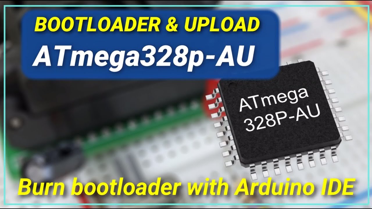
Quickly burn a bootloader to Atmega328 TQFP 32 pin chip using a USBASP programmer without needing to use an Arduino as ISP. This is an easy tutorial to use the Arduino IDE alone to program and upload your sketch on the fly while the SMD chip is still in your breadboard.
Arduino Minicore URL: https://mcudude.github.io/MiniCore/package_MCUdude_Mi...
north stream
pine bramble
How can I get from a program in my computer, a value which will then save to the...
You can send data over the serial port and read it at the Arduino end, you can either design your own simple protocol or use a fancy one such as XDR or Firmata.
 brazen falcon
Update the firmware on the usbasp to the latest, and use the slow programming mode.
pine bramble
north stream
You can send data over the serial port and read it at the Arduino end, you can e...
Ah okayyyyy Thankyou
And saving the data?
north stream
There are four major choices for saving data on the Arduino end: 1) write it to RAM (only good if the power won't go off) 2) write it to EEPROM, 3) write it to flash, and 4) write it to external storage (SD card, FRAM chip, etc.)
 quick sinew
man.. why are my messages not showing up... grr
ok... I'll start again
Bah.. ok. So I have an API that is really simple. It takes a basic json packet and logs out the contents. I've tested it locally and on the server with postman. Both work. When I try to post to it using my FONA it failed, I got a 305. I noticed that it was using http... so I changed the url in the FONAtest sample code to https... but its just coming back failed, and there's nothing on the server. Do I need to do anything special to make FONA post to https (the api is https only)
Sample code including https

Logs from FONA
16:28:27.427 -> FONA> W 16:28:47.786 -> NOTE: in beta! Use simple websites to post! 16:28:47.786 -> URL to post (e.g. httpbin.org/post): 16:28:47.786 -> https://myapiurl/api/Ingest/UploadData 16:28:50.073 -> Data to post (e.g. "foo" or "{"simple":"json"}"): 16:28:59.967 -> {"data": "a bit of posted data from the arduino"} 16:28:59.967 -> **** 16:29:00.004 -> ---> AT+HTTPTERM 16:29:00.080 -> <--- OK 16:29:00.118 -> ---> AT+HTTPINIT 16:29:00.152 -> <--- OK 16:29:00.190 -> ---> AT+HTTPPARA="CID" 16:29:00.264 -> <--- OK 16:29:00.302 -> ---> AT+HTTPPARA="UA" 16:29:00.378 -> <--- OK 16:29:00.416 -> ---> AT+HTTPPARA="URL" 16:29:00.563 -> <--- OK 16:29:00.600 -> ---> AT+HTTPPARA="CONTENT" 16:29:00.715 -> <--- OK 16:29:00.753 -> ---> AT+HTTPDATA=49,10000 16:29:00.829 -> <--- DOWNLOAD 16:29:00.943 -> <--- OK 16:29:00.981 -> ---> AT+HTTPACTION=1 16:29:01.057 -> <--- OK 16:29:01.095 -> Status: 601 16:29:01.095 -> Len: 0 16:29:01.133 -> ---> AT+HTTPREAD 16:29:01.171 -> <--- OK 16:29:01.209 -> Failed! 16:29:01.209 -> FONA>
rugged mirage
brazen falcon
Update the firmware on the usbasp to the latest, and use the slow programming mo...
Thanks I’ll try this
north stream
quick sinew
Bah.. ok. So I have an API that is really simple. It takes a basic json packet a...
HTTPS requires Certificates and the like to authenticate the server, which is fairly complicated.
quick sinew
Dang… gonna have to see if I can reconfigure the API. Ta.
rich coral
Adafruit SdFat does not work with mbed.h somehow
new (_event + 1) F(std::move(f));```can you program PIO to be a periodic interrupt ?
 velvet galleon
I am trying to connect a FRAM breakout to a Metro M0 on a second I2C bus using the instructions at https://learn.adafruit.com/using-atsamd21-sercom-to-add-more-spi-i2c-serial-ports/creating-a-new-wire

Adafruit Learning System
Get more high speed serial commports without bitbanging
#include "Adafruit_FRAM_I2C.h"
#include <Wire.h>
#include "wiring_private.h"

Adafruit_FRAM_I2C fram;
TwoWire myWire(&sercom1, 11, 13);

void setup()
{
  Serial.begin(115200);
  while (!Serial)
  {
  };
  myWire.begin();
  pinPeripheral(11, PIO_SERCOM);
  pinPeripheral(13, PIO_SERCOM);
  if (fram.begin(0x50))
  {
    Serial.println("Found I2C FRAM");
  }
  else
  {
    Serial.println("I2C FRAM not identified ... check your connections?\r\n");
    while (true)
    {
    };
  };

  uint8_t number{42};
  Serial.println("Writing number to address 0x00");
  fram.write(0x00, number);
  Serial.print("Read back number: ");
  Serial.println(fram.read(0x00));
}

void loop(void)
{
}
This code works fine with the connections on the standard pins. When I add '&myWire' as a parameter on the fram.begin call and move the connections to pins 11 and 13, it fails. Any ideas? Anything I should be looking for in the libraries? I see the same problem with other breakouts.
cedar mountain
velvet galleon
This code works fine with the connections on the standard pins. When I add '&myW...
I'm not too familiar with SERCOM, but it looks a little weird to have the pinPeripheral() calls after the myWire construction and setup. So you might try commenting those out or moving them before the begin().
pine bramble
fram code orthogonal to TwoWire myWire(&sercom1, 11, 13); so of course it works when you put it on the default i2c pins.
The example makes this clear.
Comments at end of line say SERCOM3 and schematic does not disagree.
So, the default i2c port for Metro M0 is SERCOM3 (on PA22/PA23).
velvet galleon
cedar mountain
I'm not too familiar with SERCOM, but it looks a little weird to have the `pinPe...
I agree. The example shows the order above, but the comments on the page say "We have to tell the Arduino core to change the MUX type before we reassign the SERCOM to this pin." I tried it both ways with no change in behavior.
velvet galleon
pine bramble
The example makes this clear.
I agree. I used the default pins in my example to show the hardware setup is correct. As you note, the default SCL is PA22 or pin 20 and the default SDA is PA23 or pin 21 (on sercom3 pads 0 and 1 respectively, per https://github.com/adafruit/Adafruit-Metro-M0-Express-PCB/blob/6cdfd4d238f82ee87c0b3b3b91f90878fcc6a125/Adafruit Metro M0 Express Pinout.pdf). The referenced link for connecting via a second I2C bus and other sources indicate that SDA on pin 11 (PA16) and SCL on pin 13 (PA17) should work with sercom1. I also tried SDA on D4 and SCL on D3 with sercom2 early in the test cycle with no success. Where is the reference to the schematic that you mention?
pine bramble
This 'code' disguised as something coherent 'compiles' -
NO idea if it does anything relevant at all:
#include "Adafruit_FRAM_I2C.h"
TwoWire myWire(&sercom1, 11, 13);
Adafruit_FRAM_I2C fram = Adafruit_FRAM_I2C();
void setup() {
    fram.begin(0x50, &myWire);
}
void loop() { }
schematics are on the Download page for each product.
pine bramble
expanded (also compiles clean; may be nonsense ;) here:
#include "Adafruit_FRAM_I2C.h"
#include <Wire.h>
#include "wiring_private.h"

TwoWire myWire(&sercom1, 11, 13);
Adafruit_FRAM_I2C fram = Adafruit_FRAM_I2C();

void setup() {
    fram.begin(0x50, &myWire);
    pinPeripheral(11, PIO_SERCOM);
    pinPeripheral(13, PIO_SERCOM);
}
void loop() { }
 thorny lintel
With displaying "videos" through hex on OLED screens, is there any way to do this more efficiently?
Even with a super short animation the storage on an Arduino Nano gets filled up instantly, actually struggling to fit anything on it
Using the Adafruit_SH1106 library, a 128x64 screen
Just can't find much online regarding a different method
velvet galleon
pine bramble
```cpp
#include "Adafruit_FRAM_I2C.h"
#include <Wire.h>
#include "wiring_private...
Correct, the code compiles and runs with the 2nd Wire passed to the FRAM, but it doesn't work. A symptom appears in the SERCOM::startTransmissionWIRE method. When using sercom3 the bus is idle but when using sercom1 it is busy.
opal iris
Is it possible to dump a code automatically from sd card to arduino?
 foggy anchor
hello , does anybody know how to use the wizfi360 on arduino
?
with a rasberry pico
pine bramble
velvet galleon
Correct, the code compiles and runs with the 2nd Wire passed to the FRAM, but it...
You can gain some insights using start.atmel.com but it's a long and gradual path towards knowledge, doing things that way.
That's what I did (idk 3 or 4 summers ago ;).
pine bramble
SCL:PA09 (D3) with SDA:PA16 (D11)
SCL:PA09 (D3) with SDA:PA08 (D4)
SCL:PA09 (D3) with SDA:PA12 (D28)
(Metro M0 Express specific)
 sour chasm
I'm trying to compile the OozeMaster3000 code for a Feather M0, but the Arduino IDE is throwing the following error:
exec: "C:\Users\tophe\OneDrive\Documents\ArduinoData\packages\adafruit\tools\arm-none-eabi-gcc\9-2019q4/bin/arm-none-eabi-g++": file does not exist
Error compiling for board Adafruit Feather M0 Express (SAMD21).
I've got the board and libraries loaded in the managers. Can anybody point me to my issue?
pine bramble
It's not finding the compiler. What did you change?
sour chasm
Yes, both Arduino and Adafruit SAMD board packages are loaded. I don't think I changed anything from the default load?
Now it's throwing these additional errors. Do I need to roll back to an older package?
Could not find boards.txt in C:...\ArduinoData\packages\adafruit\hardware\avr\1.4.14. Is it pre-1.5?
Could not find boards.txt in C:...\ArduinoData\packages\adafruit\hardware\nrf52\1.1.0. Is it pre-1.5?
Could not find boards.txt in C:...\ArduinoData\packages\adafruit\hardware\avr\1.4.14. Is it pre-1.5?
north stream
opal iris
Is it possible to dump a code automatically from sd card to arduino?
I'm not sure what you're trying to do here. Like use an SD card as extended flash where you can load programs from it and run them?
leaden walrus
sour chasm
Yes, both Arduino and Adafruit SAMD board packages are loaded. I don't think I c...
are you getting errors even attempting to upload the blink example?
https://learn.adafruit.com/adafruit-feather-m0-express-designed-for-circuit-python-circuitpython/using-with-arduino-ide#blink-2854174
sour chasm
leaden walrus
are you getting errors even attempting to upload the blink example?
<https://lea...
Yep, same error. I can compile a different sketch for an Arduino Nano just fine. I must have something wrong in the IDE installation?
leaden walrus
yah. somethings up with your arduino ide install. were SAMD boards ever working?
sour chasm
No, this is the first time I've tried running arduino code on one of the SAMD feathers. I usually work in circuitpython.
leaden walrus
did the board support install seem to go OK?
added URL in prefs
installed packages via Board Manager
?
sour chasm
Yep. I'm trying an uninstall and clean re-install right now. I do have a lot of old libraries and crap from sketches I no longer need. Maybe the detritus is messing something up.
leaden walrus
ok. if you're doing a clean re-install, there's one trick to that.
need to manually delete a directory
youre on windows?
sour chasm
Yes
leaden walrus
C:\Users(username)\AppData\Local\Arduino15
north stream
Note that for the SAMD Feathers, you'll need to install both the Arduino SAMD board support as well as the AdaFruit SAMD board support (the AdaFruit package uses pieces from the Arduino one)
sour chasm
Roger.
sour chasm
leaden walrus
` C:\Users(username)\AppData\Local\Arduino15`
Odd, I'm not finding that directory anywhere.
leaden walrus
C:\Users\tophe\OneDrive\Documents\ArduinoData\ check under here?
sour chasm
Ah, I had to nuke that entire folder, so it may have been hiding in there.
Oh the fun never stops. Reinstalled IDE, now when I try to add the Arduino SAMD (haven't added the URL for adafruit to preferences yet), I get, 'CRC doesn't match, file is corrupted. It may be a temporary problem, retry later.'
I'm going to take a break.
opal iris
north stream
I'm not sure what you're trying to do here. Like use an SD card as extended fla...
I am programming an arduino wirelessly, so I was thinking of using sd card as a device which receives hex file from lora and stores it in sd card and then from sd card i want to flash arduino uno.
cedar mountain
opal iris
I am programming an arduino wirelessly, so I was thinking of using sd card as a ...
That sounds like you essentially want a bootloader on the Uno which knows how to flash itself from SD. That's not impossible, but you'll be somewhat resource-constrained. I'm not sure if there's an existing bootloader which does that already out there.
north stream
opal iris
I am programming an arduino wirelessly, so I was thinking of using sd card as a ...
That would be reasonably straightforward if you had a second CPU that talks to LoRa and the SD card, then acts as a programmer for the Arduino.
 warm wave
Hello, hopefully this is in the right place
So I was wondering if anyone could help me with the seeed studio XIAO SAMD21

Seeed Studio XIAO SAMD21 is the first pioneering product of the XIAO series featuring the SAMD21 microchip and is Arduino-compatible. With its exquisite design, low power consumption, and built-in Type-C, it's perfect for TinyML, smart wearable devices, and IoT projects.
More specifically the datasheet says it has 11 analog pins and looking at the datasheet it says One 12-bit, 350ksps Analog-to-Digital Converter (ADC) with up to 20 channels, does that mean that each channel/pin is sampled at 350ksps, is it divided by all 11 so like 31.8ksps, or say if you're only using two, it'll sample both of them at 175ksps?
What's the max current that I can draw from the 5v and 3.3v line on pins eight and 10?
Say if I had two leds connected to it on the gpio pins and I set it up so that the sketch just blinks the first led every second forever. If I made a windows program with the purpose of selecting which led to blink, how would I go on to interface with the microcontroller? The only thing that I can think of is that since it has 32KB of SRAM, could I make it so that it always shows up as a flash drive or something then have the program change say a one for the first led to two to the second led to which the microcontroller would read it and know which one to flash?
sour chasm
sour chasm
Oh the fun never stops. Reinstalled IDE, now when I try to add the Arduino SAMD ...
Fixed! I'll post this here for anyone who might run into a similar wall. The solution was to delete everything in the ..[username]/AppData/Local/Temp folder. Something hiding in there was corrupted and causing the board package download to fail. And even better, the entire remove/reinstall IDE process has fixed my original issue. Oozemaster now compiles just fine. Thanks everyone for the help.
north stream
warm wave
More specifically the datasheet says it has 11 analog pins and looking at the da...
There's just one converter that's shared among those pins. So the converter runs at the same sample rate, and your program would control how it's connected to the inputs you're using. You could use a simple round-robin approach reading each input in turn, in which case, the conversion rate would effectively be divided up by the number of inputs you're using. But since you're in control, you could divide it up differently, for example you could have one input you wanted to sample quickly so you could sample it every other time, so it would have half the conversion rate, and the other inputs would run slower.
 lean verge
Hello can somebody help with PCA9685 16 Channel 12 Bit PWM Servo Driver. Wiring VCC -> 5v, SDA - > A5, SCL -> A4 and GND -> GND. I have this simple code and it doesn't work on any of my servos.
#include <Wire.h>
#include <Adafruit_PWMServoDriver.h>
Adafruit_PWMServoDriver pwm = Adafruit_PWMServoDriver();
void setup() {
  // put your setup code here, to run once:
  pwm.begin();
  delay(10);
}

void loop() {
  // put your main code here, to run repeatedly:
  pwm.setPWM(1, 0, 500);
  delay(500);
  pwm.setPWM(1, 0, 150);
  delay(500);
  pwm.setPWM(1, 0, 350);
  delay(500);
}

help plz ?
north stream
lean verge
Hello can somebody help with PCA9685 16 Channel 12 Bit PWM Servo Driver. Wiring...
You'll need to connect V+ as well to supply power to the servos
lean verge
i have done that, and out of 5 servos 2 of them works
and yes 5 servos works I have checked with normal servo library
north stream
Ah, when you said "it doesn't work on any", I figured that meant none of them.
north stream
Have you tried the servo example? There are several parameters that have to be set properly to generate a servo waveform (instead of a generic PWM signal)
lean verge
Yes and then they all work but when i want to use pwm.setPWM() then the servos dont work
lean verge
north stream
Have you tried the servo example? There are several parameters that have to be ...
Such as ?
north stream
Such as the ones in the example like pwm.setPWMFreq(SERVO_FREQ);
lean verge
And after that the PWM.setpwm() will work ?
north stream
What I would do is start with the (working) servo example and change one piece at a time until it does what you want.
warm wave
north stream
There's just one converter that's shared among those pins. So the converter run...
Ah I see
Thanks!
Any idea on the other questions?
Or like where to find the answer?
I still can't seem to figure it out...
.<
:c
north stream
warm wave
Any idea on the other questions?
I don't know the max current offhand, normally I try to stay away from the max anyway.
As for controlling it, implementing a mass storage device is probably overkill, my usual approach is to use the virtual USB serial port to send commands, and have it read the information and act on it in its main loop.
warm wave
north stream
I don't know the max current offhand, normally I try to stay away from the max a...
Yeah that's why I wanna know the max, so I don't go near it lol
warm wave
north stream
As for controlling it, implementing a mass storage device is probably overkill, ...
Ohhh
Didn't know that's how you were supposed to do it
Thanks! <3
^-^
north stream
warm wave
Ohhh
I don't know how you're "supposed" to do it, that's just how I often do it.
north stream
warm wave
Yeah that's why I wanna know the max, so I don't go near it lol
You can find information like that in the processor data sheet. In this case, it's on page 876, and shows for 3.3V operation, you can source up to 2mA or sink up to 2.5mA for standard drive strength, or source up to 7mA or sink up to 10mA for high drive strength.

 elfin gazelle
I am trying to do something with multiple counters/timers. Is there a way to do what I am doing atm with just one function. When I would call SequenceA with different variables I wont have to independent counters. ```c++
void setup() {
// put your setup code here, to run once:
Serial.begin(9600);
}
void loop() {
// put your main code here, to run repeatedly:
unsigned long currentMs = millis();
Serial.print(sequenceA(12, 500, currentMs));
Serial.print(" ");
Serial.println(sequenceB(4,300, currentMs));
}
int sequenceA(int maxCount, int interval, int current) {
static int count;
static unsigned long previousMs = 0;
if(current - previousMs >= interval){
count ++;
previousMs = current;
}
if (count == maxCount){
count = 0;
}
return count;
}
int sequenceB(int maxCount, int interval, int current) {
static int count;
static unsigned long previousMs = 0;
if(current - previousMs >= interval){
count ++;
previousMs = current;
}
if (count == maxCount){
count = 0;
}
return count;
}
There are some useful concepts here: https://learn.adafruit.com/multi-tasking-the-arduino-part-1

Adafruit Learning System
Make your Arduino walk and chew gum at the same time.
brazen falcon
There's also the option of using the hardware timers directly, but at that point you're really arduino in name only.
 mortal ridge
Hello would someone be able to help me with an issue that I have no solution for. I have a serial monitor testing the stuff for a button board. I was going one by one adding them. When I hit the 6th button nothing shows in the serial monitor AT ALL. But once I comment out anything with button 6 it works.
WORKING MONITOR WITH 5 BUTTONS: PT1
#include <SPI.h>
#include <RF24.h>
#include <nRF24L01.h>

#define BUTTON1_PIN 3
#define BUTTON1_INDEX 0

#define BUTTON2_PIN 4
#define BUTTON2_INDEX 1

#define BUTTON3_PIN 5
#define BUTTON3_INDEX 2

#define BUTTON4_PIN 6
#define BUTTON4_INDEX 3

#define BUTTON5_PIN 9
#define BUTTON5_INDEX 4

//#define BUTTON6_PIN 10
//#define BUTTON6_INDEX 5

#define CNS 7
#define CE 8
#define PACKET_SIZE 7

const uint64_t pipe = 0xE8E8F0F0E1LL;

RF24 radio(CNS,CE); //CNS , CE
byte data[PACKET_SIZE];

//bool p_ButtonState1 = false;
//bool buttonToggle1 = false;

//bool p_ButtonState2 = false;
//bool buttonToggle2 = false;

//bool p_ButtonState3 = false;
//bool buttonToggle3 = false;

//bool p_ButtonState4 = false;
//bool buttonToggle4 = false;


void setup() {
  Serial.begin(9600);

  //Reciever Setup
  radio.begin();
  radio.openWritingPipe(pipe);

  //Button Setup
  pinMode(BUTTON1_PIN,INPUT);
  pinMode(BUTTON2_PIN,INPUT);
  pinMode(BUTTON3_PIN,INPUT);
  pinMode(BUTTON4_PIN,INPUT);
  pinMode(BUTTON5_PIN,INPUT);
  //pinMode(BUTTON6_PIN,INPUT);

}```PT2
  bool stale = false;

  bool button1 = digitalRead(BUTTON1_PIN);
  bool button2 = digitalRead(BUTTON2_PIN);
  bool button3 = digitalRead(BUTTON3_PIN);
  bool button4 = digitalRead(BUTTON4_PIN);
  bool button5 = digitalRead(BUTTON5_PIN);
  //bool button6 = digitalRead(BUTTON6_PIN);


  data[BUTTON1_INDEX] = button1;
  data[BUTTON2_INDEX] = button2;
  data[BUTTON3_INDEX] = button3;
  data[BUTTON4_INDEX] = button4;
  data[BUTTON5_INDEX] = button5;
  //data[BUTTON6_INDEX] = button6;


  radio.write(data,sizeof(data));
  Serial.print(data[0]);
  Serial.print(" ");
  Serial.print(data[1]);
  Serial.print(" ");
  Serial.print(data[2]);
  Serial.print(" ");
  Serial.print(data[3]);
  Serial.print(" ");
  Serial.println(data[4]);
  //Serial.print(" ");
  //Serial.println(data[5]);

  /*
  //Button 1 Toggle Logic
  if (p_ButtonState1 == false && button1 == true){
    buttonToggle1 = !buttonToggle1;
    stale = true;
    data[BUTTON1_INDEX] = buttonToggle1;
  }
   Serial.println(buttonToggle1);
  */

  /*
  //Checks if changes were made
  if (stale){
    radio.write(data, sizeof(data));
  }

  //Updates the button state

  p_ButtonState1 = button1;
  */
  delay(30);

}```Are you 100% sure about the pin numbering for button 6? I'm wondering if setting that pin to input mode is messing with some other function on the board.
mortal ridge
yes I am. It is an Arduino nano and it is right next to 9
thats why im so confused about this
and if I leave the code as is and change the pin of 5 to 10 it also breaks.
north stream
I'm guessing pin 10 has something to do with the radio.
cedar mountain
Yeah, it's the default chip select for the SPI bus, so I'm wondering about that too.
mortal ridge
hmmm
is there a way to change that
I have no other ports left like at all
I am also running the wireless module as well
so I am maxed out
 quick maple
run a resistor with an order of magnitude off each other to each button on the same pin
read the voltage
apply ohm law
mortal ridge
I have resistors going to every pin right now
goes from 5v to button, button to pin on a breadboard
north stream
You're using all the analog pins too?
north stream
Yup
north stream
Yes. digitalRead(), digitalWrite(), pinMode(), etc. work fine on the analog pins.
mortal ridge
oh snap
leme try that
but for future stuff is there a way to use the coms pins like 10 11 and 12 for normal use?
seems like a waste otherwise
north stream
If you're using them for SPI, you can't really use them for something else as well
cedar mountain
mortal ridge
but for future stuff is there a way to use the coms pins like 10 11 and 12 for n...
You should be able to, so I'm confused why it's not working. Might be some subtlety of the nRF library's use of SPI.
mortal ridge
ohhh
ok
darn
so never uised analog
do I just use digitalread(a1) instead
like whats its name
normal pins are just numbers
north stream
You can refer to it as A1 or it's apparently also GPIO 14
 cedar mountain
Yep, you'd refer to them as A1 or similar. Under the hood the Arduino headers define those names with an internal pin number.
mortal ridge
hmmmmm
mortal ridge
it worked! thank you
warm wave
north stream
I don't know how you're "supposed" to do it, that's just how I often do it.
Ohhh okayy
warm wave
north stream
You can find information like that in the processor data sheet. In this case, i...
Oh...
That's not a lot at all
Was hoping to drive leds on it lol
Uhh, any idea how I can split off the usb 5v power while it also being plugged into the usb c port?
Like thinking maybe soldering wires to the usb c port's power connectors or something then into a resistor to get it down to led voltage levels?
cedar mountain
What is "it" in this case? A lot of Adafruit boards have a 5V pin that taps off the USB power for this sort of purpose.
warm wave
cedar mountain
What is "it" in this case? A lot of Adafruit boards have a 5V pin that taps off ...
Oh, it's this

Seeed Studio XIAO SAMD21 is the first pioneering product of the XIAO series featuring the SAMD21 microchip and is Arduino-compatible. With its exquisite design, low power consumption, and built-in Type-C, it's perfect for TinyML, smart wearable devices, and IoT projects.
Didn't know that some boards have a 5v pin to tap off of
I've never really messed with arduinos before
.<
cedar mountain
Yeah, that looks like it has a 5V pin in the corner too.
warm wave
cedar mountain
Yeah, that looks like it has a 5V pin in the corner too.
Ohhh, is that what the vin and gnd pads on the bottom of the board are for?
cedar mountain
I can't immediately find a schematic, so it's not 100% clear what the relation between the USB 5V and the VIN pins are. The simplest thing would be that they're just connected, but sometimes there are protection diodes too.
warm wave
That's the chip schematic but idk if you're looking for the board schematic though
Also wait, is vin for voltage in like to be used with a battery or something and not an output?
cedar mountain
warm wave
Also wait, is vin for voltage in like to be used with a battery or something and...
Yeah, that's the question. They could have made the board to handle power in a few ways.
warm wave
cedar mountain
Yeah, that's the question. They could have made the board to handle power in a f...
Oh
 jolly axle
The product wiki says:
For power supply pins: The built-in DC-DC converter circuit able to change 5V voltage into 3.3V allows to power the device with a 5V supply via VIN-PIN and 5V-PIN.
https://wiki.seeedstudio.com/Seeeduino-XIAO/
Seeed Product Document
cedar mountain
Ah, if there's a separate VIN pin and 5V pin, then chances are good that the 5V one is direct to the USB power.
jolly axle
The link has this schematic
 warm wave
north stream
You can find information like that in the processor data sheet. In this case, i...
warm wave
north stream
You can find information like that in the processor data sheet. In this case, i...
Not sure if that applies to 5v too?
warm wave
Also is it possible to read from the analog pin then right after output on the same pin, not analog but to light up and power an led?
Something like this?
input = analogread(pin1);
if (input == 1000){um uh output(pin1) or something like that??}
Also if that is possible and fine to do, would I be correct in assuming that it'd essentially be blinking but like really fast, so fast that it would look like it's constantly on?
warm wave
The reason being is that I plan to use the seeeduino xiao and I want to use multiple load cells on the different adc inputs/pins but if I wanted to use leds to show that they're being registered on different pins, I'd run out of pins hence why I want to use the same pin
north stream
warm wave
Not sure if that applies to 5v too?
The SAMD21 does not support 5V operation.
north stream
warm wave
Also is it possible to read from the analog pin then right after output on the s...
Yes, you'd have to change the pin mode, but that's valid, as long as the circuitry connected to the pin isn't going to mess with each other or your readings.
warm wave
north stream
The SAMD21 does not support 5V operation.
Oh, I'm confused
I mean like on the board there's a 5v pin, from what I understand that's a pass through of the 5v from the usb c port?
If so, like how much current can I get from that?
warm wave
north stream
Yes, you'd have to change the pin mode, but that's valid, as long as the circuit...
Ah I see, well just in case it doesn't work out
north stream
Yes, that's the input to the on-board regulator, presumably. You could likely get at least 500mA, minus whatever the board itself is drawing. More depends on the capability of your 5V supply and the traces on the board.
warm wave
Do you know of a cheap way to be able to turn on and off a bunch of simple leds?
Not the four pin rgb ones but like just the two pin ones?
Like some sort of cheap chip that I can just connect the seeed to with a single pin or something then use that to solder a bunch of leds to?
warm wave
north stream
Yes, that's the input to the on-board regulator, presumably. You could likely g...
Oh I see, so basically if I can't find actual specs for it, just don't push it too much?
XD
north stream
Right. USB standard is 500mA, you may or may not be able to get more.
warm wave
Ohhh okayy
cedar mountain
warm wave
Like some sort of cheap chip that I can just connect the seeed to with a single ...
"Single pin" is probably hard there, but you can get ones that use just a handful of pins, like GPIO expander chips that work on I2C, or shift register chips.
rich coral
RTClib somehow corrupts RP2040 Connect, any ideas ?
the MISO LED blink fast 5 times and slow 4 times
had to load Blink.ino.elf.uf2 to restore
warm wave
cedar mountain
"Single pin" is probably hard there, but you can get ones that use just a handfu...
So the seeed xiao has 14 pins, three of them are for power, so that leaves 11, I need nine analog pins, so that leaves two, would two be enough?
Like for example, would all I need to get this board to work be two pins, SDA and SCL?

You want to make a cool robot, maybe a hexapod walker, or maybe just a piece of art with a lot of moving parts. Or maybe you want to drive a lot of LEDs with precise PWM output. Then you ...
Well two pins plus the power in I mean
Or some other board or chip?
Like I mean I don't need anything really fancy like pwm, all I need is to be able to turn two lead leds on and off
Maybe in the future use rgb leds but I'm not sure right now
Unless if rgb leds are really cheap but I'm trying to keep project costs down
.<
cedar mountain
Yep, I2C just needs two data pins. And it's a shared bus, so you can generally connect multiple boards to the same pins, too.
rich coral
DateTime now = rtc.now(); causes RP2040 Connect to die
warm wave
cedar mountain
Yep, I2C just needs two data pins. And it's a shared bus, so you can generally c...
:o
Well that's perfect then
rich coral
can anyone reproduce this problem ? just use RTClib on RP2040 connect
warm wave
cedar mountain
Yep, I2C just needs two data pins. And it's a shared bus, so you can generally c...
Erm, any idea how much power I can run through that adafruit 16 channel board?
I can't seem to find that info on the page
cedar mountain
warm wave
Erm, any idea how much power I can run through that adafruit 16 channel board?
Looks like each pin can source 10mA or sink 25mA, with a little variance with the supply voltage. (Looking at the PCA9685 datasheet.)
warm wave
cedar mountain
Looks like each pin can source 10mA or sink 25mA, with a little variance with th...
Guess I should go and look up a video on how to wire/use it
Hopefully that'll answer all my questions like how the heck do I power the leds then if not through the board itself?
😅
cedar mountain
It's optimized to sink current, so you'd generally connect the anode of the LEDs to your power supply, and the cathode of the LED to one of the pins, so the LED turns on when the pin goes low. (With a current-limiting register on one side or other of the LED too.)
warm wave
cedar mountain
It's optimized to sink current, so you'd generally connect the anode of the LEDs...
I see (well at least I think I understand that, just don't know how to wire the current limiting resistor part)
Uhh, is there another board that I can just plug leds into to make things simpler?
Like instead of it being designed to sink current, be designed to output/power stuff off of?
cedar mountain
Maybe https://www.adafruit.com/product/1455 or similar. It has a constant-current LED driver, so it doesn't need separate resistors.

For all of you out there who want to control 12 channels of PWM, we salute you! We also would like you to check out this breakout board for the TLC59711 PWM driver chip. This chip can ...
Out of stock, though, unfortunately.
warm wave
cedar mountain
Maybe https://www.adafruit.com/product/1455 or similar. It has a constant-curren...
Oh, I see
So if I'm looking at the datasheet right
It says max of 60ma per channel
And in the description it says that the resistor is set to 15ma
So I can only drive four leds per channel with it?
cedar mountain
warm wave
So I can only drive four leds per channel with it?
Normally you'd only be driving one LED per channel with a chip like this. If you had multiples, they would need their own current-limiting resistors to equalize them, etc. so the constant-current supply isn't helping much.
Maybe back up a second... exactly how many LEDs do you want to control, how bright, and how much control do you need in terms of PWM or individual sequences? You might be happier with NeoPixels in the end.
warm wave
Oh, uhhh not sure how many but uhm a lot like idk maybe 50?
I was just thinking of using two lead leds because they're cheap but what's a neopixel and are they relatively cheap?
cedar mountain
A NeoPixel is Adafruit's terminology for various kind of "smart LEDs", which are full-color RGB and have built in driver circuitry to display any color. They use a daisy-chain data connection with 1 or 2 pins, so you can control hundreds of them at once. They're more expensive than regular LEDs, but once you add in the cost of breakout driver boards for normal LEDs, it kind of evens out.
Adafruit Industries, Unique & fun DIY electronics and kits : NeoPixels - Tools Gift Certificates Arduino Cables Sensors LEDs Books Breakout Boards Power EL Wire/Tape/Panel Components & Parts LCDs & Displays Wearables Prototyping Raspberry Pi Wireless Young Engineers 3D printing NeoPixels Kits & Projects Robotics & CNC Accessories Cosplay/Costumi...
warm wave
cedar mountain
A NeoPixel is Adafruit's terminology for various kind of "smart LEDs", which are...
Ohhh
Waiit
You can control hundreds of them individually with a single pin?
:o
cedar mountain
Indeed. Once you get up into the thousands range, you can start running into memory limitations or not being able to update them super-fast, but people do lots of them to make big LED displays.
warm wave
Wait
So in theory, I don't even need that i2c board and can just string a whole bunch of them together and then have them light up different zones instead of wiring different channels/pins then turning those channels/pins on?
cedar mountain
Correct. The software has an interface that says "make LED number 47 turn blue", etc. and it just happens.
warm wave
:o
cedar mountain
People really like them. 😁
warm wave
Yeah I can see why lol
So I'm looking at a strip of em, so do I wire the entire strip to a power supply and then connect the single pin to the seeed xiao?
Also do I still need resistors or is it all taken care of for me?
Oh, nevermind
Seems like this pictures answers that question lol
 rich coral
anyone got fatal error: sdkconfig.h: No such file or directory when using ESP32-S3 Feather?
rich coral
I also tried the latest arduino-esp32 from github
and upload.erase_cmd is not set
Does ESP32-S3 Feather with PSRAM even supported in Arduino ?
gilded swift
should be
according to the docs it's supported
arduino-esp32
Arduino core for the ESP32
 solemn cliff
not sure what this is highlighting ?
il reads like when setting the "erase flash" menu to "Disabled" it has no command, but when setting it to "Enabled" it adds -e to the command
rich coral
esptool write_flash: error: argument <address> <filename>: Address "{upload.erase_cmd}" must be a number
solemn cliff
so the command is wrong ? what is it for other boards ?
rich coral
WROOM2 works
esptool.exe" --chip esp32s3 --port "COM65" --baud 921600 --before default_reset --after hard_reset write_flash {upload.erase_cmd} this is where it fails
it does not know the address to write the sketch
solemn cliff
it does not properly replace the erase_cmd by the value selected in the menu ?
was it added wrong ? https://github.com/espressif/arduino-esp32/pull/7043/files
rich coral
there is no menu item and the board.txt has empty field

ok, I managed to upload blink by forcing the argument in platform.txt
rich coral
23:25:26.976 -> Calculated: 3611f330726ad4edf64f62982b0568332a5800bc59425cab90be5379db92c108
23:25:26.976 -> Expected: ffffffffffffffffffffffffffffffffffffffffffffffffffffffffffffffff```is this normal for esp32s3 ?
north stream
Looks like a checksum read error
quick maple
internet seems to says it's related to flashing from the arduino ide rathan than espressif software
have you flashed it recently ?
rich coral
yes, I use Arduino
elfin gazelle
does anyone know how I can setup arduino for VSCode on Fedora? I need to specify the path but cannot find the right path
 peak fractal
Hi there, Updating some old arduino code and for the life of me can't figure out how to update SSD1306 display(0x3c, 5, 4); to the new Adafruit_SSD1306 display(SCREEN_WIDTH, SCREEN_HEIGHT, &Wire, OLED_RESET); format? This is for a TTGO esp32 board with a built in oled screen. https://github.com/adafruit/Adafruit_SSD1306 <- is the library
GitHub
Arduino library for SSD1306 monochrome 128x64 and 128x32 OLEDs - GitHub - adafruit/Adafruit_SSD1306: Arduino library for SSD1306 monochrome 128x64 and 128x32 OLEDs
cedar mountain
peak fractal
Hi there, Updating some old arduino code and for the life of me can't figure out...
It looks like the Adafruit library auto-determines the I2C address from the display height, so the 0x3C parameter wouldn't be needed. And the 5 and 4 parameters I presume would be the I2C pins, so those would be incorporated into the Wire bus to start with.
peak fractal
cedar mountain
It looks like the Adafruit library auto-determines the I2C address from the disp...
Thanks, Gotcha so I need to be looking at how to initiate wire with those pin defs... Also it looks like the address is sent into display.begin() in the shipped example .ino.
cedar mountain
peak fractal
Thanks, Gotcha so I need to be looking at how to initiate wire with those pin de...
Probably there would be a Wire or Wire1 object already set up if those are standard I2C pins on the board you have, so it would just be a matter of figuring out which bus it is.
peak fractal
cedar mountain
Probably there would be a `Wire` or `Wire1` object already set up if those are s...
This seems like it's passing the entire library... &Wire , I tried to define the pins as both SDA/SCL and I2C_SDA, I2C_SCL but it looks like I'll be diving into the CPP file to see if there's an override or def I'm missing... It doesn't look like there's a wire1 object
Got it, had to change line 522 of https://github.com/adafruit/Adafruit_SSD1306/blob/master/Adafruit_SSD1306.cpp to wire.begin(5,4) now the question is how could I have defined or passed that from my user code instead of modifying the library?
GitHub
Arduino library for SSD1306 monochrome 128x64 and 128x32 OLEDs - Adafruit_SSD1306/Adafruit_SSD1306.cpp at master · adafruit/Adafruit_SSD1306
Yay!
 solemn cliff
peak fractal
Got it, had to change line 522 of https://github.com/adafruit/Adafruit_SSD1306/b...
solemn cliff
peak fractal
Got it, had to change line 522 of https://github.com/adafruit/Adafruit_SSD1306/b...
looks like it has constructors for that ?
https://github.com/adafruit/Adafruit_SSD1306/blob/88711efc3e4b4a1a3fb238a1c5aa9590697f9c02/Adafruit_SSD1306.cpp#L144-L146
peak fractal
solemn cliff
looks like it has constructors for that ?
<https://github.com/adafruit/Adafruit_...
In the example code this is passing the entire library without a call to .begin() should I instantiate an instance of wire with the .begin(5,4) call and pass that?
solemn cliff
"passing the entire library" ?
peak fractal
https://github.com/adafruit/Adafruit_SSD1306/blob/88711efc3e4b4a1a3fb238a1c5aa9590697f9c02/examples/ssd1306_128x32_i2c/ssd1306_128x32_i2c.ino#L36 I guess the library instantiates a wire object and it's passing that?
GitHub
Arduino library for SSD1306 monochrome 128x64 and 128x32 OLEDs - Adafruit_SSD1306/ssd1306_128x32_i2c.ino at 88711efc3e4b4a1a3fb238a1c5aa9590697f9c02 · adafruit/Adafruit_SSD1306
solemn cliff
it's passing the default I2C bus instance
it's not python, libraries are not objects you pass 😉
peak fractal
True 🙂 I am working in a ipythonnotebook today as well 🙂
Thanks for the help I think I understand now
solemn cliff
that whole thing where Arduino prefers to use the default Wire instance is always confusing, I can't say that I see many examples of initing a different one
peak fractal
Could be that my board def is wrong. I selected esp32_dev board but that could be wrong
solemn cliff
like, yeah in the docs they talk about Wire as "the library" (like begin() "inits the library") and that's confusing, but it actually does that:
TwoWire Wire = TwoWire(something);
Oh that's what I needed!
solemn cliff
like that:
packages/esp32/hardware/esp32/2.0.4/libraries/Wire/src/Wire.cpp
519:    TwoWire * wire = (TwoWire*)arg;
533:    TwoWire * wire = (TwoWire*)arg;
556:TwoWire Wire = TwoWire(0);
557:TwoWire Wire1 = TwoWire(1);

packages/arduino/hardware/sam/1.6.12/libraries/Wire/src/Wire.cpp
404:TwoWire Wire = TwoWire(WIRE_INTERFACE, Wire_Init, Wire_Deinit);
442:TwoWire Wire1 = TwoWire(WIRE1_INTERFACE, Wire1_Init, Wire1_Deinit);

...
it seems like on ESP32 you can do:
Wire.initPins(int sdaPin, int sclPin)
(thus using the chip's I2C peripheral 0 with the designated pins)
peak fractal
Ok that's a private method but found I can just do Wire.begin(5,4) in the setup method before calling display.begin and it works
  Wire.begin(I2C_SDA, I2C_SCL);

  Serial.begin(115200);
  Serial.println(F("SSD1306 allocation trial"));
  // SSD1306_SWITCHCAPVCC = generate display voltage from 3.3V internally
  if(!display.begin(SSD1306_SWITCHCAPVCC, SCREEN_ADDRESS)) {
    Serial.println(F("SSD1306 allocation failed"));
    for(;;); // Don't proceed, loop forever
} ```I have problem with RTCLib with arduino-pico core
DS3231 cannot be detected, maybe RTClib does something to I2C mux ?
quick maple
rich coral
I have problem with RTCLib with arduino-pico core
what board? is ds3231 onboard or not ?
and do you have an ic2 component between the board and the ds3231 like ic2 backpack or shifter or such? (as soon as I use a PFC backpack for my LCD Wire stops working for me and I have to adress it manually)
rich coral
DS3231 breakout and ItsyBitsy RP2040\
on circuipython it works fine
but with arduino-pico core it cannot detect DS3231
My guess is RTClib messed up I2C mux\
north stream
If you have an I2C mux, you'll need to set it to point to the correct bus first.
rich coral
any way to access Arduino RP2040 connect QSPI flash?
north stream
I'm not sure what you're asking. The RP2040 does have a QSPI port it can use to access off chip flash memory.
rich coral
RP2040 Connect has 16MiB on board flash connected to QSPI
 tulip nebula
If I code directly to the MCU in C, will that be much more power efficient / faster than using the Arduino language?
cedar mountain
tulip nebula
If I code directly to the MCU in C, will that be much more power efficient / fas...
Arduino is also C++, so it would be basically the same, depending on how efficient your C is versus how efficient the Arduino library writers can code.
 dense galleon
Could anyone let me know is there an example of Bluefruit plotter showing analogue in, please?
wraith current
I can't figure out which constructor to use in u8g2 to get the 128x64 oled featherwing to work. I've tried all of these : U8G2_SH1107_64X128_1_SW_I2C(rotation, clock, data [, reset]) [page buffer, size = 64 bytes] U8G2_SH1107_64X128_2_SW_I2C(rotation, clock, data [, reset]) [page buffer, size = 128 bytes] U8G2_SH1107_64X128_F_SW_I2C(rotation, clock, data [, reset]) [full framebuffer, size = 1024 bytes] U8G2_SH1107_64X128_1_HW_I2C(rotation, [reset [, clock, data]]) [page buffer, size = 64 bytes] U8G2_SH1107_64X128_2_HW_I2C(rotation, [reset [, clock, data]]) [page buffer, size = 128 bytes] U8G2_SH1107_64X128_F_HW_I2C(rotation, [reset [, clock, data]]) [full framebuffer, size = 1024 bytes]
oh, nevermind, had the SCL pin wrong. This one seems to work : m_u8g2 = new U8G2_SH1107_64X128_F_SW_I2C(U8G2_R0, /* clock=*/ 5, /* data=*/ 4, /* reset=*/ 16);
 glossy cradle
Good morning everyone. I am currently using an Arduino Mega to read 16 analog inputs using the ADC, I am wondering however, when I disconnect one of the adc pins the voltage read does not drop to 0?
If I ground it the value goes to 0 as expected, but as soon as I unground it again the voltage reading jumps back up to the other voltage values
north stream
glossy cradle
Good morning everyone. I am currently using an Arduino Mega to read 16 analog in...
They're high impedance inputs, designed that way so they don't load down whatever they're connected to. Because of this, if they aren't connected, their voltage will tend to "float" to unpredictable values.
glossy cradle
Thanks again madbodger, so it's not really something to be concerned about.
Now on to calibrate 16 op amps for resistor mismatch 
And 16 shunt resistor values, as track length is not the same so have a little inaccuracy there too 
north stream
I had a project a while back to characterize resistor arrays but there wasn't the space or budget to construct an on-board ohmmeter. I ended up applying voltage and ground to various combinations of pins, and measuring the resulting voltage on the remaining pins, basically using the array as various combinations of voltage dividers. It worked pretty well, and the people running the project were impressed with my "zero extra parts" solution.
glossy cradle
That's pretty smart, I haven't found many creative solutions to my problems yet. But I have my trusty Keithley to compensate with precision what I lack for in knowledge.
Each line is the voltage drop from a current shunt, can see purple and green are pretty close. But red and blue have some obviously different resistance due to track lengths.
 north stream
To my surprise and glee, the US Patent Office agreed with you (patent number 9,996,996)
That's a good graphic, I like it!
glossy cradle
Grats on the patent, my first patent application they decided not worth patenting. Submitting another patent somewhere next year hope it goes better.
Thanks this is the full one, bottom bar chart shows how much mA is flowing through the 4 resistors for each of the 4 boards. Just for some live visualisation.
 north stream
I'm a big fan of good visualizations, well done!
glossy cradle
Thanks again, I am off to start calibrating. Have a nice day madbodger, always nice to chat with you.
 raven vale
Anyone have any experience playing I2S audio from a MAX98357 audio amplifier on an RP2040 board in Arduino? I’m trying to adapt a project from CPY to Arduino code but I am getting stuck trying to play WAV files and send them out via I2S on a Pico
Can’t find many examples of audio playback code that use the RP2040 and many of the examples I’m finding use libraries that aren’t available yet for RP2040
inland gorge
raven vale
Can’t find many examples of audio playback code that use the RP2040 and many of ...
Do you mean output directly from the RP2040 (presumably as PWM) or via an outboard I2S chip?
Do you want WAV playback or sound synthesis?
For WAV play via I2S, there are many examples. Here's one fairly complex one: https://github.com/elehobica/RPi_Pico_WAV_Player
For WAV play via PWM, here's an example using the very complete arduino-audio-tools: https://www.pschatzmann.ch/home/2021/06/30/pwm-audio-output/
(The github link in his blog post is a bit stale, the new one is: https://github.com/pschatzmann/arduino-audio-tools/tree/main/examples/examples-stream/streams-memory_wav-pwm )
GitHub
Arduino Audio Tools (Music Player, Music Recorder supporting I2S, Microphones, DAC, ADC, A2DP, Url, MP3, AAC, AudioKit, ES8388) - arduino-audio-tools/examples/examples-stream/streams-memory_wav-pwm...
raven vale
inland gorge
Do you mean output directly from the RP2040 (presumably as PWM) or via an outboa...
Thanks! That's helpful - I am just getting familiar with the arduino langue and have not really had much experience with c++, but I'll give that example a look over and see if I can make sense of how to incorporate that into an arduino sketch
inland gorge
raven vale
Thanks! That's helpful - I am just getting familiar with the arduino langue and ...
Doing audio on Arduino is a pretty pro-level move. If you're interested in more immediate results, I'd recommend CircuitPython. (I do both, Arduino can do synthesis but CircuitPython is great if you just want to trigger a WAV now and then)
raven vale
Yeah it's a lot 🙂 - I already got my project working in CPY and I'm pretty happy with it. The primary reason I'm trying to port it over to Arduino is just to learn Arduino
it's definitely a learning curve
native dagger
Do all adafruit arduino libraries work with all adafruit boards?
leaden walrus
no. there are some too big to work on uno, for example.
and for others, could be hardware related - missing required hw, etc.
native dagger
hmm OK, how can I check?
quick maple
the code
will usually mention a type and pin type, and it will usually have defines for boards
raven vale
native dagger
hmm OK, how can I check?
If you follow the link to a libraries documentation pages, there’s usually some information about which boards it’s compatible with.
grave tundra

I've been trying to initialise The "AsyncTCP.h" & "ESPAsyncWebServer.h", I've already downloaded the libraries.
But I'm not able to access it, can somebody help me out ?
I've already included the zip files inside Arduino IDE
north stream
Normally you'd unzip the files and put the contents in the libraries directory in your arduino source directory.
Or just install them with the Library Manager if that option is available.
grave tundra
Just tried what you said, It still doesn't seem to be working.
C:\Program Files (x86)\Arduino\libraries
I've copied the files inside this library.
north stream
That's the Arduino program directory, the libraries directory goes in the arduino source directory where your sketches live
 north stream
What happens when you try to compile your code?
 north stream
The important part is off the screen to the right, where it says "fatal error: sd...."
It looks like you have installed the libraries in more than one location as well, hence the "multiple libraries" warning
Your first screen shot includes some text like "library added to your libraries" so it was probably already installed at that point, and your issue was something else.
grave tundra
What might be the issue, as I've already tested it in 2 laptops and I'm getting the same issue.
north stream
Unfortunately, the important part of the error message is off the screen to the right so I can't read it
 north stream
Ah, that is a weird known subtle problem: the expressif ESP32 board libraries are not compatible with the ESP8266 community libraries. You probably need to remove whichever ones don't match your board.
grave tundra
I'll try to uninstall Arduino IDE and reinstall it
dense galleon
https://learn.adafruit.com/introducing-the-adafruit-nrf52840-feather/custom-hrm
Could anyone help with this, please? I dont know how to set up this...
It shows "ERROR: Notify not set in the CCCD or not connected!" in Serial Monitor.

Adafruit Learning System
The first Bluefruit Feather with USB and CircuitPython support
opal iris
can someone help me to solve this issue, please
ModuleNotFoundError: No module named 'serial'
exit status 1
Error compiling for board ESP32 Dev Module.
 quaint nebula
Good afternoon all - hoping for some help with Qt-Py ESP32-S2. I have three. Two of them are not behaving correctly today - can't say for sure what caused the issue, so let's just describe the symptoms. I opened the third (untouched) one to check default behaviour, and as expected it has the neopixel cycling through the colors (I'll try and attach a short video to illustrate this and the problem ones). A second Qt-Py ESP32-S2 is showing on/off red/blue together every one second. The third one is showing about a six or seven second cycle, mostly showing red, with a quick flash or green then blue before going back to red. Have done a bit of digging and have yet to locate anything that says what these sequences mean. It's probably out there somewhere - please point me in the right direction. I have tried getting into BOOT mode, and have dragged over the reset UF2 file (qt-py-esp32-s2-factory-reset.uf2) to the QTPYS2BOOT drive. It comes back with the same neopixel sequence. I have not yet tried the Factory Reset and Bootloader repair option. Grateful for any suggestions! Thanks!
quaint nebula
quaint nebula
Good afternoon all - hoping for some help with Qt-Py ESP32-S2. I have three. Two...
Well, some progress! Turns out option 3 (red for a long time, followed by blue/green in quick succession) is apparently the default behaviour after a basic factory reset. I had thought it would be the same as when it came out of the 'box', but it is subtly different. However, when connected up to the serial monitor it seems to be outputting a wifi scan, and the lights align with when it's printing out the results to serial. So that's OK. And on further examination it would seem that the red/blue together every 1 second or so, is most likely an issue with the sketch I was trying to run (my fault for over-simplifying I guess!), and it's just in a reboot cycle.
I had been trying to troubleshoot some analog read code I have via a multiplexer (aiming for 24 sliders + pots via three 74HC4051 multiplexers). It was working fine on an UNO (one analog pin to 8 sliders), but with the Qt-Py I was getting a lot of noise. Interestingly I thought the ADC was 12 bit on the Qt-Py, based on the product page, but am getting values in range 0-8191 (13-bit), which Espressif says is what the chip does (https://docs.espressif.com/projects/esp-idf/en/v4.2.3/esp32s2/api-reference/peripherals/adc.html). But I was getting variations of up to about 1.5% to 2%, sometimes more unless the pot was pinned at 0 or max. This seems rather high. Happy to handle up to about 0.5% noise as I'm only outputting MIDI (0-127) values, so that should be OK. On the UNO noise was about 0.3% or less.
So today's code was trying to simplify to see exactly what the noise looked like on one channel rather than all 8 channels on the multiplexer. Somewhere I must have mucked up the code, because I think the blue/red neopixel indication is a constant reboot state - so back to the drawing board on that!
If anyone knows more about noise on ADC on ESP32-S2 (ideally on the Qt-Py) please add something here! All suggestions welcome.
 river garnet
Is there a way to disable sleep on the Adafruit ESP32 Feather V2? - It looks like it does it automatically after a while -- my circuit becomes unresponsive to wifi.
cedar mountain
river garnet
Is there a way to disable sleep on the Adafruit ESP32 Feather V2? - It looks lik...
I'd be a little surprised if a built-in sleep mode is the culprit there, since that's not a typically microcontroller feature unless specially implemented. Are you sure your code isn't just crashing?
 grizzled vault
Hey can someone help me figure out why this won't compile?
"/home/----/arduino/ESP8266_Router_Honeypot.ino:56: undefined reference to 'dhcps_set_dns'
Collect2: error: ld returned 1 exit status
Exit status 1
Error compiling for board LOLIN(WEMOS) D1 mini (clone)"
I don't know c. I don't know what it wants me to fix or how lol
Obviously it wants the variable defined, but what is wrong in the sketch, or how to do so
north stream
That's a linker error, not a compiler error, so it's looking for a symbol in a library and not finding it. This is often because the library itself is not being properly included.
grizzled vault
First step troubleshoot?
north stream
Did you install the ESPcanary library?
grizzled vault
Yes
north stream
A little poking around on the 'net reveals dhcps_set_DNS() with "DNS" in capitol letters, but the error message shows it in lower case: which is it in your .ino file?
grizzled vault
Lowercase
north stream
Hmmm. I darkly suspect this is a versioning problem. There appear to be a couple of different versions of the support libraries, with slightly different calls. If you don't have the matching environment, you'll get errors like that. Unfortunately, I don't have that setup here and don't know how to fix it.
There are some mentions to different ESP8266 support packages, it might be worth trying a different one?
rugged mirage
anyone know off the top of their head where I need to connect an external clock to an atmega4808, I know with the 328p its through xtal1 and xtal2 with capacitors to GND, but the 4808 datasheet makes it seem like I need to connect a clock signal to a single pin. Am I responsible for making my own oscillator circuit and just putting the squarewave output on that pin? or am I missing something easier? I don't want to use the internal oscillator because I'm not exactly sure how accurate it is.
maybe this is more suited for the hw-design channel
cedar mountain
rugged mirage
anyone know off the top of their head where I need to connect an external clock ...
Yeah, that's how I read it. It can accept an external square-wave clock signal, but it doesn't actually have the circuitry to drive a high-speed crystal. Instead of rolling your own circuit for that, you'd typically just use an off-the-shelf oscillator part if the internal oscillator isn't good enough.
If you wanted to get fancy, you could probably use a 32kHz crystal to calibrate the internal oscillator to a tighter tolerance.
rugged mirage
Okay cool I’m glad I’m getting better that I had the answer pigeonholed. I’ll test it with the internal oscillator and see how it goes, my worry comes from building this circuit with a Chinese nano knock off and the oscillator built on to the board being really cheap. But I’ve read pretty good things about the oscillator in the 4808
 wet siren
what is the difference between 12v and 5v 28BYJ-48 motors? i plan to convert them to bipolar motors by cutting the trace link to run them with a4988 drivers
native dagger
speaking as someone who primarily writes python, when writing arduino or C++ (or even C), are there any tools of similar power to the REPL? I'm familiar with using the serial monitor but it's not quite the same as the REPL in terms of power. Anything like that?
tardy iron
native dagger
speaking as someone who primarily writes python, when writing arduino or C++ (or...
if you want to be able to interactively inspect and modify memory, and even interactively call functions, you might want to look into boards that support debuggers. sadly, Arduino itself doesn't directly support debuggers yet
cedar mountain
native dagger
speaking as someone who primarily writes python, when writing arduino or C++ (or...
It's not Arduino-specific, but for general semi-interactive C/C++, there are online tools like https://godbolt.org/

 native dagger
cedar mountain
It's not Arduino-specific, but for general semi-interactive C/C++, there are onl...
native dagger
cedar mountain
It's not Arduino-specific, but for general semi-interactive C/C++, there are onl...
Cool thanks
 waxen pewter
Hi! I am trying to set up SPI communication between an ESP32 (given the schematic below) and a BME680. I am trying to use the BSEC library for this, and I am having a hard time getting the BME680 to be identified by the ESP32.
#include <bsec.h>
#include <SPI.h>

#define BME_SCK 0
#define BME_SDO 12
#define BME_SDI 27
#define BME_CS 26

SPIClass bmeSpi(HSPI);
Bsec iaqSensor;

void setup()
{
    bmeSpi.begin();
    bmeSpi.begin(BME_SCK, BME_SDI, BME_SDO, BME_CS);

    iaqSensor.begin(BME_CS, bmeSpi);
}

void loop()
{
    if (!iaqSensor.run())
        { // If no data is available
          return;
        }
}
I believe that the issue lies with how I use the SPIClass initialization. I tried to set up bmeSpi both with HSPI and BME_CS, but neither worked. The status of the board is always BME680_E_DEV_NOT_FOUND.
 native dagger
So how do I figure out from here https://github.com/adafruit/Adafruit_VS1053_Library which microcontrollers this library works with?
architectures in library.properties just says "*"
tardy iron
skimming the code, it doesn't seem to use too much hardware-specific stuff
the main exception seems to be interrupt-related functionality, which does have some architecture dependencies
native dagger
I saw basic stuff in there, where should I look to read about the interrupt stuff?
mostly I'm trying to see if I can run this on an M0
Or an RP2040
native dagger
OK so it seems there's a possible wrinkle? Here's the IF/DEFs for the "current feather boards" as of the writing of the article. Obviously the RP2040 isn't there. Let me see if the pins on the feather that line up with the pins on the featherwing are compatible.

ok the SPi pins line up to SPI pins and the control pins line up to GPIO
OK it looks like it'll be fine, I think any GPIO can be used for interrupts on the RP2040
The question I have is: where do I put the IF/DEF logic for the RP2040? In the place where globals are set up? Or elsewhere?
 frank linden
Hi, I'm trying to upload code to an ESP32-S3 Feather 2MB SRAM but I keep getting the error 'sdkconfig.h: No such file or directory' on both computer I have tried it on. However I have no problem uploading to my ESP32-S3 Feather TFT which I imagine is pretty much the same board. Could anyone provide some guidance on this? Thanks! Edit: Figured out that my clone of the arduino-esp32 repo was a couple of weeks out of date, so for anyone having this issue in the future, double check you are on the latest commit of that.
pine bramble
but I’ve recently done the adafruit atari joystick with the adafruit nRF52 - and gotten it working -ish. The mister fpga nd retroarch both really need the thing to be gamepad HID and not just a keyboard HID -can anyone help?
For example.. jumping in a commodore 64 game requires the input to receive a right directional signal from the joystick and up direction at the same time… Or a fire button press and left right at the same time... with keyboard acting as joystick input, this doesn’t work.
 mortal seal
Rp2040 qt
 next edge
Heya, trying to get a Pimironi SCD41 to work with a FeatherS2 via QT, but just getting Error trying to execute stopPeriodicMeasurement(): Received NACK on transmit of address on the serial monitor. Is there a different serial address I should have in the code?
AFAIK it should be 0x62 but I can't find that configured in the code...
Weirdly my I2C scan is also coming up empty.
Ah, I was having ArduinoSDK use Adafruit's Feather32-S2 not UM's FeatherS2... argh.
 thick stag
I'm trying to pass pixels to function so that I can do more advanced stuff with it.
#include <Adafruit_NeoPixel.h>

Adafruit_NeoPixel pixels = Adafruit_NeoPixel(PIXEL_COUNT, NEO_PIN, NEO_GRB + NEO_KHZ800);

void setup()
{
  pixels.begin();
}

void loop()
{
  turnOn(pixels);
}

void turnOn(Adafruit_NeoPixel &pixels){
   for(int i=0;i<PIXEL_COUNT;i++){
    pixels.setPixelColor(i, pixels.Color(redColor, greenColor, blueColor));
  }
  pixels.show();
}
^ This is what I have but Arduino is not happy with my turnOn function. What am I missing here?
tardy iron
you need to forward-declare the function, or easier, just move it before anything that calls it
(i think Arduino tries to auto-generate function prototypes where needed, but it can get them wrong, in my experience)
thick stag
#include <Adafruit_NeoPixel.h>

Adafruit_NeoPixel pixels = Adafruit_NeoPixel(8, 5, NEO_GRB + NEO_KHZ800);

void turnOn(Adafruit_NeoPixel &pixels){
  for(int i=0;i<8;i++){
    pixels.setPixelColor(i, pixels.Color(0, 0, 0));
  }
  pixels.show();
}

void setup()
{
  pixels.begin();
}

void loop()
{
  turnOn(pixels);
}
Is giving
1:13: error: variable or field 'turnOn' declared void


1:13: error: 'Adafruit_NeoPixel' was not declared in this scope
1:32: error: 'pixels' was not declared in this scope
are those the entire error messages? are you using the Arduino IDE?
 wary venture
I'm trying to use the sensor calibration library (for Adafriut_AHRS) in PlatformIO and getting the error "Adafruit_Sensor_Calibration_SDFat.h:14:10: fatal error: Adafruit_SPIFlash.h: No such file or directory" despite Adafruit_SPIFlash being installed and includable from my main code.
 split citrus
Has anyone been having issues with their arduino 2.8” TFT touch shield? The arduino IDE says my code compiles and is “done uploading” and “verify successful” but the screen remains a blank white
north stream
Could be a pinout / connection issue
pine bramble
Anyone have tips on getting Adafruit M0 boards to work with Arduino IDE (Mac)? I bought a couple of Trinket M0s, installed the boards in the Board Manager, everything worked okay for the first one. I went back to flash another one today, no matter what I try the IDE doesn't seem to see it. It has power, the onboard LED is on and blue. USB cord seems to be able to connect to other things so not that. Tried to reinstall the boards definitions. At a bit of a loss beyond just trying to do it on another OS/computer 🤷
tardy iron
pine bramble
Anyone have tips on getting Adafruit M0 boards to work with Arduino IDE (Mac)? I...
the Trinket M0 looks like it has native USB, which means that an error in a sketch can prevent it from reacting correctly to the signaling from the Arduino IDE to put it into bootloader mode. have you tried manually entering bootloader mode? https://learn.adafruit.com/adafruit-trinket-m0-circuitpython-arduino/uf2-bootloader-details
north stream
pine bramble
Anyone have tips on getting Adafruit M0 boards to work with Arduino IDE (Mac)? I...
Does it enumerate as a serial device?
pine bramble
tardy iron
the Trinket M0 looks like it has native USB, which means that an error in a sket...
Ha, I tried this before but it looks like this did the trick this time. I finally see it, thanks
 wild fern
I was working my way through the setup guide for the Adafruit ESP32 Feather V2 and reached the point where I was trying to compile a blink program (https://learn.adafruit.com/adafruit-esp32-feather-v2/blink) but I encountered the following compile error.
Arduino: 1.8.19 (Mac OS X), Board: "Adafruit Feather ESP32 V2, Core 1, Core 1, Enabled, Default (3MB APP/1.5MB SPIFFS), 240MHz (WiFi/BT), 80MHz, 8MB (64Mb), 115200, None, Disabled"
Traceback (most recent call last):
File "esptool/loader.py", line 48, in <module>
File "PyInstaller/loader/pyimod02_importers.py", line 493, in exec_module
File "serial/tools/list_ports.py", line 31, in <module>
File "PyInstaller/loader/pyimod02_importers.py", line 493, in exec_module
File "serial/tools/list_ports_posix.py", line 33, in <module>
File "PyInstaller/loader/pyimod02_importers.py", line 493, in exec_module
File "serial/tools/list_ports_osx.py", line 26, in <module>
File "PyInstaller/loader/pyimod02_importers.py", line 493, in exec_module
File "ctypes/init.py", line 7, in <module>
ImportError: dlopen(/var/folders/kp/27c_gh757jg68g99ppdnsddh0000gn/T/_MEIg7EIDP/lib-dynload/_ctypes.cpython-38-darwin.so, 2): Symbol not found: _ffi_closure_alloc
Referenced from: /var/folders/kp/27c_gh757jg68g99ppdnsddh0000gn/T/_MEIg7EIDP/lib-dynload/_ctypes.cpython-38-darwin.so (which was built for Mac OS X 10.15)
Expected in: /usr/lib/libffi.dylib
in /var/folders/kp/27c_gh757jg68g99ppdnsddh0000gn/T/_MEIg7EIDP/lib-dynload/_ctypes.cpython-38-darwin.so
Can anyone help me to diagnose the problem?
 leaden walrus
did you install the ESP32 BSP per the guide?
tardy iron
wild fern
I was working my way through the setup guide for the Adafruit ESP32 Feather V2 a...
i think you're running too old a macOS for the esptool in the BSP. it's depending on system libraries that are newer than the version of macOS you're running. (i've complained about this before, to no avail)
wild fern
leaden walrus
did you install the ESP32 BSP per the guide?
thanks for the feedback. @leaden walrus yeah, i tried to install the esp32 bsp as per the guide. my os is currently 10.14.6 so maybe@tardy iron has a good theory about the OS version. i noticed that the error output mentions "(which was built for Mac OS X 10.15)" maybe i'll try to update my os and see if that helps
tardy iron
wild fern
thanks for the feedback. <@337989520962093057> yeah, i tried to install the esp3...
probably a good idea to upgrade to at least 10.15, because i recall that 10.14 is no longer supported by security updates
wild fern
cool. i'll update now. see y'all on the other side (fingers crossed). lol.
wild fern
@leaden walrus and @tardy iron I updated to Catalina and reinstalled everything and it works now! Thanks for your help!
 solar aspen
Hi All - I'm trying to use an ESP32-S3 to control a Music Maker FeatherWing. I'm using the Music Maker learn guide instructions, and I get the following SPI-related compile error.
Has anyone else seen this? Something I'm doing incorrectly?
 leaden walrus
where did that SPI library come from?
solar aspen
Excellent question. I didn't explicitly install the SPI library that it's referencing.
Or at least...not recently
I was just assuming it was there by default, but looking now, I see it's in the sketch libraries directory which isn't the system libraries location
leaden walrus
yah. that's weird in terms of location. try just manually deleting it.
also make sure your ESP32 BSP is up to date
solar aspen
I just installed the latest ESP32 stuff this morning.
Removing the SPI lib got me over that hurdle
But I have a truckload of SD related errors to sort out now...
native dagger
Is there any way to prevent the arduino IDE from forgetting both that I'm not using an UNO and also forgetting my board profiles completely, forcing me to re-install them? Is the answer platformIO?
leaden walrus
"board profiles" = board support packages?
native dagger
Whatever you call what's in Tools > Board:
pine bramble
How are you starting the Arduino IDE .. clicking on something on a desktop?
leaden walrus
that setting should generally persist. sounds like it's reverting to "UNO" every time the IDE is launched?
native dagger
It's intermittent as far as I can tell.
Sometimes it's when launched, sometimes not
I just use the Taskbar and type "ardu" and click
pine bramble
I would find preferences.txt and track it carefully. Instead of being surprised every time. Surveil it in advance of each use, and 'catch it in the act'.
quick maple
native dagger
It's intermittent as far as I can tell.
windows ?
native dagger
Yup
quick maple
I don't know the solution but the problem is probably a silly thing along the lines of the current app cant access the current user folders..
pine bramble
At the top of preferences.txt is the selected board. For example:
 $  cat -n ~/.arduino15/preferences.txt | sed 1q
     1  board=adafruit_circuitplayground_m0
especially if it works fine as admin
some AV like bitdefender also blcok it more or less without telling you, or windows defender real-time protection etc... really annoying problem...
native dagger
I've been wanting to try platformIO for a while so I'll see if that does it better
quick maple
I doubt it, app have no control on your UAC or antivirus policies
and app are supposed to save in %appdata% for the user or the documents of the user
native dagger
I just use windows defender
quick maple
where is preferences.txt file actually ?
native dagger
I'm away from my PC right now
quick maple
ie: start a cmd as admin and do dir /s preferences.txt from the root c:\ folder
ok well pretty sure the problem is the ide doesn't get permission to write its own files
windows store or normal version?
solar aspen
Any ideas as to why a call to musicPlayer.begin() for the Music Maker FeatherWing would reset an ESP32-S3?
solar aspen
No issues with an M4 Express.
leaden walrus
may be related to this?
https://github.com/adafruit/Adafruit_VS1053_Library/issues/45
solar aspen
I'll check it out. Thanks for the reference.
The great thing about the Feather ecosystem is that I can close my eyes, randomly lay my hand down somewhere within reach, and I'll likely be touching a Feather of another flavor. SAMD51, STM32, NRF52, etc. The M4E has allowed me to keep moving on the audio control bits for now. I'll come back to the main controller eventually.
 hexed sphinx
Hi all,
I want to tilt compensate a HMC5883L 3-axis magnetometer with pitch&roll values from a Adafruit BNO055 module using this formula:
  Xh = magXRaw * cos(pitch*degToRad) + magYRaw * sin(roll*degToRad) * sin(pitch*degToRad) - magZRaw * cos(roll*degToRad) * sin(pitch*degToRad);
  Yh = magYRaw * cos(roll*degToRad) + magZRaw * sin(roll*degToRad);

  if (Yh < 0){
    heading = 180 + (180 + ((atan2(Yh, Xh)) * (180 / PI)));
  }
  else{
    heading = (atan2(Yh, Xh)) * (180 / PI);
  }
I succeeded to create a tilt compensated compass with the BNO055 magnetometers, accelerometers & gyros. But the HMC5883L 3-axis magnetometer has way more steady values and is low noise, so I would want to use the BNO055 for pitch&roll and the HMC5883L for magnetometer values.
The problem is that when I put the BNO055 and the HMC5883L on the same breadboard with the axises in the same direction, I get different magnetometer values... This makes it not possible to change the BNO055 magnetometer values in the tilt-compensation formula with the HMC5883L magnetometer values...
Has anyone any idea why the magnetometer values from the BNO055 and the HMC5883L would be different?
pine bramble
How can i set the Certificate in my arduino Code while using the tinygsm library?
i am trying to establish a connection to aws iot core using simcom GSMModem SIM7080
This Post explains my problem
https://stackoverflow.com/questions/63643007/esp32-x509-over-gprs-to-aws-mqtt-8883

Stack Overflow
i am new to iot and aws, i am facing a problem communicating with aws mqtt over gsm module
first i used an example to communicate with AWS MQTT using a WIFI library by setting the private,root,and
quick maple
are you the one who posted that question?!
pine bramble
quick maple
are you the one who posted that question?!
Nope But i'm having the same problem aswell
is there any solution for setting the Certificate While using the GSM module instead of WIFI?
wraith current
@pine brambleI know that with wifi you can setInsecure() to ignore certs but you can't with tinygsm.
pine bramble
wraith current
<@456226577798135808>I know that with wifi you can setInsecure() to ignore certs...
what i am trying to achieve is actually the opposite, I am not trying to ignore certs b
but instead trying to load them
in the wifi i can do
  espClient.setCertificate(pRead_cert);
  espClient.setPrivateKey(pRead_privatekey);
but i'm not finding any instructions on how can i do this with my GSM modules
quick maple
why do you want to do this with your GSM? has nothing to do with the amazon sdk
amazon don't even provide code for arduino so you'll have to do with from scratch
pine bramble
quick maple
why do you want to do this with your GSM? has nothing to do with the amazon sdk
Correct
quick maple
GSM only require you user/*pass, unlocking your SIM etc
pine bramble
quick maple
amazon don't even provide code for arduino so you'll have to do with from scratc...
yes, correct
pine bramble
quick maple
GSM only require you user/*pass, unlocking your SIM etc
Sorry what?
quick maple
I don't understand the link between certificates and GSM
tinygsm docs don't even mention certificates
the tinygsm library might not even be the right library for GSMModem SIM7080
pine bramble
The certificates are required in order to connect a device to AWS IoT Core, These are used as an authentication
pine bramble
quick maple
the tinygsm library might not even be the right library for GSMModem SIM7080
Why not?
quick maple
because there are many hardware for GSM, library typically handle a few not all of them
you need to make sure tinygsm actually support your gsm chip/expansion card/shield etc
pine bramble
quick maple
you need to make sure tinygsm actually support your gsm chip/expansion card/shie...
Ok well, It says it on their official Github page, i don't know what can be more official than this
https://github.com/vshymanskyy/TinyGSM

GitHub
A small Arduino library for GSM modules, that just works - GitHub - vshymanskyy/TinyGSM: A small Arduino library for GSM modules, that just works
 quick maple
Don't see certificate on that page though ?
pine bramble
sorry i am just not understanding the point you're trying to make,
quick maple
I'm trying to tell you to make baby steps because the way you are describing the problem atm is vague
Have you even got the GSM to works like in the getting started section ? What happens when you try to add the certificates as in TinyGsmClientSIM7080.h ? etc
pine bramble
Have you ever worked with AWS IoT core ?
quick maple
if no error does the certificates actually show up on the storage of the phone... etc
pine bramble
pine bramble
Have you ever worked with AWS IoT core ?
?
wraith current
@pine brambleyeah, not sure what to do if there are not methods for adding the certs to the gsm. maybe they need to be set in a different way.
pine bramble
wraith current
<@456226577798135808>yeah, not sure what to do if there are not methods for addi...
as far as i've researched, people are able to set the certificates using the manual AT Commands which is a bit complex, I don't have much experience working with GSM modules Over AT Commands, so was looking for an alternative,
wraith current
ahh ok. well the tinygsm library is just a layer ontop of the AT commands. did you search the issues in tinygsm library ?
TinyGsmClient base_client(modem, 0);
SSLClient secure_layer(&base_client);
//Add CA Certificate
secure_layer.setCACert(root_ca);
``` from https://github.com/kiddtang/SSLClient/blob/master/examples/Esp32/https_gsm_SIM7600/https_post_sim7600/https_post_sim7600.ino
GitHub
SSLClient - generic secure client Arduino library using mbedtls - SSLClient/https_post_sim7600.ino at master · kiddtang/SSLClient
pine bramble
https://github.com/vshymanskyy/TinyGSM/issues/136
Going over this Thread

GitHub
Hi, does TinyGSM support tls 1.2 over GSM ? I want to see the possibility of connecting to AWS IoT over GSM. But finding none.
pine bramble
wraith current
```// HTTPS Transport
TinyGsmClient base_client(modem, 0);
SSLClient secure_laye...
oh wow
Thank you so much
wraith current
ok. good luck. gotta go. Hope that works !
 grim bane
Has anyone here ever used this AK8975 accelerometer module? I am having issues connecting to it through I²C on an Arduino mega. Using the I²C scanner sketch it never detects the module as connected. There is a voltage of about ~4.4V going through the SDA and SCL pins wether it's being powered by 3.3V or 5V.
HiLetgo 2pcs AK8975 3-Axis Accelerometer Gyroscope Compass Sensor High Precison Compass Sensor Module IIC I2C SPI 3-5V https://a.co/d/ilurGWI

HiLetgo 2pcs AK8975 3-Axis Accelerometer Gyroscope Compass Sensor High Precison Compass Sensor Module IIC I2C SPI 3-5V
cedar mountain
grim bane
Has anyone here ever used this AK8975 accelerometer module? I am having issues c...
I tend to disbelieve the result of measuring 4.4V out if it's only getting 3.3V in, so there's probably something weird about your setup.
grim bane
Yeah I was kinda confused about that too. I tested another I²C module and it was outputting about ~4.8V and the scanner was actually picking it up
All I have connected is gnd, vcc, SDA, and SCL.
leaden walrus
does the breakout pull CSB high? otherwise, would need to do that manually to set I2C mode.

 sturdy plover
I am trying to run this (https://learn.adafruit.com/adafruit-feather-sense/arduino-sensor-example) sketch for my feather bluefruit sense and am having the following issue, here is my log: https://pastebin.com/LxdXu2VD

Pastebin
Pastebin.com is the number one paste tool since 2002. Pastebin is a website where you can store text online for a set period of time.
gilded swift
sturdy plover
I am trying to run this (https://learn.adafruit.com/adafruit-feather-sense/ardui...
In your Arduino libraries folder, is there an Adafruit_sensor.h file at all?
Usually this happens when dependencies are not installed or are installed in the wrong directory
grim bane
leaden walrus
Can you explain what you mean by CSB pulling high? Or send a link that explains it, not sure what I'd google for that.
leaden walrus
grim bane
Can you explain what you mean by CSB pulling high? Or send a link that explains ...
the sensor supports SPI and I2C interfaces
for I2C to work, CSB needs to be connected to VID (see datasheet)
if that's not somehow done on the breakout, you'll need to do that manually
grim bane
there is no VID pin on the headers though, would connecting it to VCC work..?
@leaden walrus
leaden walrus
maybe
if that's the same as VID, then yes
but would depend on breakout design
are schematics available?
grim bane
of this breakout? I haven't been able to find any
leaden walrus
or any info on how to use with i2c?
grim bane
nope lol, I found these github repos but they're more about the AK8975 chip and not the breakout https://github.com/jrowberg/i2cdevlib/tree/master/Arduino/AK8975
GitHub
I2C device library collection for AVR/Arduino or other C++-based MCUs - i2cdevlib/Arduino/AK8975 at master · jrowberg/i2cdevlib
quick maple
VCC is usually power in yes if you aren't sure check for continuity between VCC and GND pins
also does it matter that much if you don't know if there is a pullup, just put one, worse that can happen is that it has too much ohms and doesn't work perfectly?
grim bane
I tried connecting to CSB pin to every other header and the only one that showed any change was connecting it to SDA but it was just errors @quick maple
I've tried at 3.3v on VCC and 5v on vcc
quick maple
but did you add pullups resistors on both SDA and SCL? Is it the first time you use I2C ?
grim bane
Any other time I've used I2C I've never had to add the pullup resistors
leaden walrus
i2c requires pullups. they have to be included somewhere on the bus.
adafruit breakouts put them on the breakout
quick maple
you bought a cheap breakout it's not unexpected that it doesn't include pullups, whereas adafruit is a bit more $ and include such things to make your life easier
happened to me a week ago so I feel you, I also couldn't understand why they didn't put pullups on the oled, but it's life
i2c without these isn't plug-n-play
grim bane
I see, I'll try that in a second
quick maple
you may have to set a jumper or solder a test pad somewhere to give it an adress for I2C but this is above my level. Once sda/scl are correctly powered and i2c scan should find the adress so you can use it
grim bane
@leaden walrus @quick maple does the ohms of the resistor matter..?
quick maple
yes, it depends on the MCU and voltage of the target board
10k ohm is typically used for a normal (ie: not a computer like the pi) 3.3V sensor/MCU
and 40k ohm is used for 5V
leaden walrus
somewhat. you can generally get away with a wide range of values. 10kohm is a good starting value.
grim bane
okay
leaden walrus
actually - "yes, it depends" is better wording than "somewhat"
quick maple
I think the learn article could use an improvement and be clearer on suggested values without having to read the schematics/computer the resistors color codes
since it's core knowledge
grim bane
tried with 10k, 20k and 47k on both 3.3V and 5V and nothin :/
grim bane


 quick maple
yeah your resistors are connected to ground as I though
they should be connected to 5V/3.3V rail on the breadbound not ground
grim bane
They're not connected to ground if you look close at the wire. I see why you think that though
Bad picture lol
quick maple
they are on the same rail as the grey wire
that comes out from the GND pin on the sensor
grim bane
No they're on the same rail as the orange.
quick maple
ah nvm, optical illusion on 1st pic 😄
grim bane
These are 47k resistors
tardy iron
Yellow-Violet-Black-Red… 47k? that seems a bit large for I2C
quick maple
too much, the goal is to keep the pins ABOVE a certain voltage
grim bane
I've tried 10k and 20k as well same thing.
quick maple
I have to go back to work so hopefully someone can help were you able to do the continuity test to test if the sensor is DOA or not ?
tardy iron
10k might also be too big. what I/O voltage are you using?
grim bane
I've tried both 5v and 3.3v @tardy iron