
#help-with-robotics
1 messages · Page 10 of 1
 sterile silo
 primal shell
That board has a lot of options, I think you can send it RC style PWM, serial commands, analog control, and possibly some others.
 harsh hill
sterile silo
Could someone please help point me in a direction of how to connect one of Adafr...
harsh hill
sterile silo
Could someone please help point me in a direction of how to connect one of Adafr...
I would use serial to connect to it, the manual should have details on how to configure all the jumpers required and some pseudocode on how to control it.
sterile silo
Thanks @primal shell & @harsh hill But I'm hoping to get more simplified help in learning / figuring out how to get the OSPoC prototype working. The way my autistic brain is wired, I'm having an extremely hard time processing & learning how to correctly wire & program the RageBridge V2 with one of the Circuit Python capable Adafruit boards from the level of tutorials that they have out there.
harsh hill
sterile silo
Thanks <@!348911944486486016> & <@!609329377850949632> But I'm hoping to get mo...
Do you have any particular board in mind you want to use? I can probably draw a circuit diagram for it later today.
sterile silo
That'd be so appreciated @harsh hill . I have all the boards that came in AdaBox's 009 - 018, just let me know which one you think would be the most effective, lol, or just pick one that you prefer.
harsh hill
Do you have any other requirements like wifi, Bluetooth, etc? And do you prefer circuitpython or arduino?
sterile silo


Bare, with me, I'm still writing to answer just putting some pics up.


Na, I need to keep it simple, but ya Circuit Python please. Having it run on CP, & CP's user friendliness is actually going to be one of the main marketable points.
So the RageBridge V2, the Adafruit board, a joystick (I don't have the joystick on my white board any where yet) (I have one of the kind of joysticks out of an old power chair) (pics above), I was able to figure out how to get the RC function of the RBV2 (if I understand the RBV2 sheet right, I think I'll be able to have a switch to toggle from RC to Adafruit board control with the joystick), hence the pic of my messy desk. The white board pic is my rough mock up of what I've figured I need the setup to be like. Please feel free to change if you think something would be better another way.
There we go @harsh hill , I hope that mess makes sense.
harsh hill
@sterile silo after looking though all the boards in the past 9 adaboxes I think the circuit playground bluefruit will be best as I couldn’t see any feather boards. Connect the tx pin of the circuit playground to the rx pin of the motor board. The ch3 pin should be connected to ground for the motor board to accept serial commands.
sterile silo
O' I forgot, I also have the feather that came in AdaBox 008, the robot AdaBox
harsh hill
To control the board create a serial device with a speed of 19200. Sending 0x00 will shutdown the motor controller. A value between 0x01 and 0x7f will control the first motor with 0x80 to 0xff for the second motor. The values in the middle of those ranges, 0x40 and 0xc0, will stop each of the motors.
 harsh hill
Using the itsy bitsy or the circuit playground bluefruit comes down to personal preference, it shouldn’t make much of a difference other than size and number of pins. I would avoid the m0 boards as they are not as fast as the nrf52840.
The circuit playground bluefruit also has some sensors built in which you may want to use
sterile silo
So the little Itsy Bitsy is actually more capable then the much bigger feather?
harsh hill
For the feather in the picture yes but there are feather boards that are much faster than that itsy bitsy
sterile silo
Which of the feathers do you think would be the best choice?
harsh hill
I doubt you will need higher speed than the boards you already have
The samd52 m4 and stm32f4 boards will be faster but it shouldn’t be necessary.
sterile silo
Keep in mind also, that which ever one is chosen is going to be used in production of the customer units.
I wonder which ones have the chip availability given the current conditions
harsh hill
If you care about more consistent availability the boards using the rp2040 could be a good choice, I heard the chips have better availability than the samd and stm32 chips. They are using a m0 core instead of an m4 but due to their high clockspeed they should be around the same speed unless you are doing floating point arithmetic.
If this is a product I would avoid the circuit playground boards and go with a board with pin headers as I don’t trust the contacts on the circuit playground boards for long term use when deployed.
sterile silo
My laymen understanding of what kind of program, wouldn't it basically just be movement of the joystick, triggers the connections to allow power to get to the relays, that then permit power to get sent to the motors, the signal from the joystick directs the motors to go the needed direction. I don't think the program needs any fanciness or certain algorithms would it? My thinking, I'd actually wondered if the needed program power chair program would be simple enough that it could probably be written with just CP block code.
harsh hill
If all you need is joystick control the board choice shouldn’t matter much at all
sterile silo
LMAO! U know whAt your right! I've been over thinking this so much! & going buggy & brain fried in the process.
harsh hill
Normally when I am advising people on robotics they are looking more into the autonomous control where the board choice matters much more so I also over complicated it.
sterile silo
Well,,, funny you should mention that...

As part of my attention getting by attending the Rochester Maker Faire with my OSPoC prototype, I want to use one of my other power chair bases & make a full size Dalek to also have at my booth.
Of course using the same open source hardware & software.
But then down the road, I want to keep giving it more & more capabilities & autonomy would be pretty awesome too. :-D
I'm already designing a special weapons modification for it. A big air cannon that the lower skirt opens & the cannon lifts into place.
harsh hill
Nice, I hope it goes well
 pine bramble
harsh hill
For the feather in the picture yes but there are feather boards that are much fa...
pine bramble
harsh hill
For the feather in the picture yes but there are feather boards that are much fa...
Actually, the family of Itsy Bitsy form factor boards has a number of options. I've been quite happy with the 120MHz Itsy Bitsy M4 Express, and Adafruit recently released the 125MHz Itsy Bitsy RP2040, which can be programmed in either C/C++ like a traditional Arduino board, CircuitPython or Micropython.
harsh hill
The itsy bitsy boards do have lots of options
sterile silo
Thanks. But getting back to the basic, could you please go back to how I connect the CPB, joystick & the RBV2? & possibly also how you get them to talk with each other?
harsh hill
Although I think the fastest feather currently is the stm32f405 which will still be faster than any itsy bitsy
Do you know if your joystick includes a voltage divider built in?
sterile silo
To be honest, I have no clue. I wasn't able to pull up much of any kind of data about it. There are so very little electronics in it.
That stm32f405 PID: 4382, looks pretty serious & capable!
harsh hill
I recently got 6 of those boards for a project, very good but a couple of limitations with USB which made it much harder to use for my project.
How many pins does the joystick have and are they labeled?
pine bramble
harsh hill
Although I think the fastest feather currently is the stm32f405 which will still...
Yes, but I'm trying from the description to understand why such a powerful board would even be necessary. If one is polling the inputs at 50Hz pretty much any would do. The STM32 are good boards if you want interrupts, the Itsy Bitsy RP2040 if you wanted to program in MicroPython. They all have their pros and cons of course...
sterile silo
8 pin & no labeling at all.


Hmm, perhaps I should work on getting one with potentiometers? Might be more user friendly.
Or would one with a voltage devider be better?
pine bramble
A potentiometer can be used as a voltage divider, with the middle pin providing you the varying voltage.
harsh hill
A voltage divider is used with potentiometers to allow the analog pins to measure the angle
pine bramble
Note that a Raspberry Pi doesn't have a built-in analog to digital converter (ADC) so you'd need to add an accessory (there are many). Microcontrollers often have multiple pins that can be used as ADC inputs.
harsh hill
The joystick may just have 4 actuators in it
sterile silo
Could you possibly look at Amazon & suggest one?
I' was trying to search, but I'm not sure what to search for.
harsh hill
Take a look at this post on the arduino forum, I think they have the same joystick as you https://forum.arduino.cc/t/setting-reference-voltages-on-outputs/154538/3
Arduino Forum
John Thanks so much for you input. It was extremely helpful and I was able to duplicate the outputs of the joystick for the most part. Still some idiosyncrasies created by the controller board that present a problem. Hopefully the attached will help in understanding. Rather than rely solely upon autonomous control, I thought it would be nice t...
You should be able to connect the pins it says changes to your microcontroller and read the value on those pins to see where the joystick is.
sterile silo
Wow! great find!
Ok, but then I'm going to need a micro controller with a bunch more pins then aren't I?
harsh hill
I think you will only need 4 pins plus power and ground
sterile silo
So that rules the CPB out.
harsh hill
So the itsy bitsy should have plenty
When the pins go high they reach 3.8v which is higher than the itsy bitsy can support
So instead power the joystick with 3.3v instead of 5v and all the pins should decrease in voltage to a safe level for the board
Connect up ground to the joystick and an analog pin to each of the output pins of the joystick that changes.
 worldly river
pine bramble
Note that a Raspberry Pi doesn't have a built-in analog to digital converter (AD...
worldly river
pine bramble
Note that a Raspberry Pi doesn't have a built-in analog to digital converter (AD...
I was thinking about this the other day, and considered putting a pico in on top of my zero w, just to act as an ADC
I bought a 3 pack of i2c ADCs, but it was $14. The pico is what, $4 (before shipping of course)
although I have something stored deep in the back of my memory telling me the pico's ADC may require an external reference for decent results?
harsh hill
worldly river
I was thinking about this the other day, and considered putting a pico in on top...
You can also use the pico to drive neopixels much better than you can with a standard pi
sterile silo
But if I'm only powering it with 3.3V, with it normally being powered with 5V, & V drops to 1.1V. If it's powered with only 3.3V will the drop down voltage be recognizable enough?
harsh hill
If it’s in an analog input pin you should be able to measure whatever the voltage is provided it isn’t over 3.3v
 harsh hill
worldly river
I was thinking about this the other day, and considered putting a pico in on top...
harsh hill
worldly river
I was thinking about this the other day, and considered putting a pico in on top...
Check out u2if, it does exactly that plus lots of extra functionality
sterile silo
Ok, any suggestions which pin might b pin 1?
sterile silo
Um, not sure.
harsh hill
But I am guessing it will be the top left pin
sterile silo
Na, the controller board didn't work, that's why I swiped the joystick off of it.
harsh hill
You may still get power out of the pins if you are lucky
sterile silo
The pin closest to the sticker right?
harsh hill
Yes
worldly river
harsh hill
You can also use the pico to drive neopixels much better than you can with a sta...
Yeah that's the kind of thing that made me think it might be better than just an ADC. I suspect the ADC performance may actually be a bit worse than a dedicated ADC (I'm not sure, haven't measured). But to have a dedicated realtime coprocessor is pretty cool and has a lot of advantages.
sterile silo
@harsh hill Whats ur impression of CircuitBrains Deluxe - CircuitPython-compatible SAMD51 Module - by Null Byte Labs
PRODUCT ID: 4802
Thinking of manufacturing options down the road
harsh hill
If you want to make a custom pcb without having to worry about implementing all the required circuits for a samd51 then it seems like a good option.
If you want to use it I would instead develop on a different samd51 board such as a m4 metro, m4 grand central, m4 feather or m4 itsy bitsy and switch to it later once you are ready for the custom pcb.
sterile silo
good point
harsh hill
It does seem a little expensive for what it is though but there aren’t really any other solutions out there like it.
sterile silo
Gotcha. Are you still willing to do a wiring diagram of how to connect the Itsy Bitsy, joystick, & RBV2?
harsh hill
If I get time today I will make one
sterile silo
Great, when u get a chance, thank you so much. 🙂
pine bramble
Sure, but what kind of performance do you really need? How often does your data change? I use an external ADC on my Pi, a Pimoroni ADS1015 when I'm measuring voltages up to +/- 24VDC, or the Adafruit ADS1015 or ADS1115 when measuring up to Vdd. The latter is rated at 860 samples/sec over I2C. That's way faster than the clock speed of my robot, which is 20Hz.
https://shop.pimoroni.com/products/ads1015-adc-breakout
https://www.adafruit.com/product/1083
https://www.adafruit.com/product/1085
harsh hill
@sterile silo didn’t get time to draw the circuit diagram for you yet, sorry about the delay. I have been very busy but I will try to get to it when I can.
sterile silo
No worries @harsh hill . I certainly understand being busy. When you get the chance, it'll be very much appreciated & helpful.
 wraith flame
Thanks so much @heavy snow. The info about the resistorless-QWIICs is gold. Found out about the M1 with Mu the hard way. Glad to know the latest beta fixes things. Cheers1
 arctic lotus
Not sure if this is the correct channel for this question, but basically I've got a semi-unknown stepper motor attached to a Dobot Conveyor Belt (https://www.dobot.cc/products/conveyor-belt-kit-overview.html), I purchased the Adafruit Stepper Hat for Raspberry Pi a while back, stripped the motor wires and attached them to M1/M2 (https://learn.adafruit.com/adafruit-dc-and-stepper-motor-hat-for-raspberry-pi) and I am using a 12V power supply. I am able to get the conveyor belt to move forward/backward but the motor makes this really loud and unpleasant grinding/vibrating/crunching noise, I have put the M1/M2 wires in all different combinations (A+/A-/B+/B-, etc.) and it always makes that sound.
Just today I purchased 2 DRV8871 drivers to try (https://www.adafruit.com/product/3190) thinking that because they are current limiting, that may solve my problem. But I'm not 100% sure.
Any one have any ideas or thoughts of other things I could try?
Here's the specs on the stepper motor on the conveyor belt:
 primal shell
Have you tried running the motor by itself (not attached to the conveyor)?
arctic lotus
It's a totally enclosed system
and I have no idea what the brand name of the motor is
so I can't unattach it from the conveyor and try it on it's own unfortuantely
primal shell
It shows a rated voltage of 3.25V, so 12V may be a bit much, but many stepper drivers are current regulated, which would avoid problems with voltage.
arctic lotus
So maybe my inklings towards using the DRV8871 will help?
primal shell
I suspect it's a mechanical problem of some sort, but don't know enough about it to speculate in any detail.
arctic lotus
it's almost like the motor is internally fighting with itself
I think I have a video of it somewhere
Ugh this video pains me
changing the code to use microstepping lowers the volume of the grinding quite a bit
primal shell
That almost sounds like a missing phase: I'd do a quick continuity test of the motor windings.
primal shell
Do you have a multimeter?
arctic lotus
yes
primal shell
Set it to measure resistance, and measure the resistance between the motor wires. You should get be able to find two pairs of wires with non-infinite resistance between them: those will be the motor windings (assuming a 4-wire bipolar stepper motor)
arctic lotus
sweet, i'll give it a go. thank you @primal shell !
 sage marsh
@fierce gyro could you pass this idea to Limor Fried or Phillip Torrone? This would be so great. These commandments are a very big list 1-,2-,.....432-,433-, 1034-... They are simple and they are complex, if you force your mind to remember yours many of yours parents commandments probabily will be very similar to my parents commandments. This in a robot would make a lot of sense, because it is so dense that a human can't really process then all at once, but a robot can.
worldly river
Eudecio, how do you know that the commandments are consistent?
with thousands of commandments, it would be difficult to make sure none of them contradicted each other
primal shell
That's true, Gödel's Incompleteness Theorem might apply.
 vagrant thunder
Do your commandments subscribe to any particular ideology when it comes to morals and ethics? Forgive me if I suggest anything you would be offended by, but I'm a bit skeptical that such a set of essentially hard-coded rules can follow anything more than maybe deontology, and the quality of this concept of yours is only as strong as the commandments your parents wrote.
I'd love to see your commandment-following robot exceed anything we've ever done as far as creating some form of basic general-AI, but it's pretty difficult to believe that your parents' commandments can singlehandedly resolve all the struggles and contradictions that plagued philosophers for the greater portion of our human history....
 steel lintel
He won't share the list of commandments, so we can't check for consistency
 lone skiff
Just translating arbitrary verbal commandments into robotic behavior is basically Turing-Test-complete AI to start with.
steel lintel
I think you'd end up with the same result as Asimov's 3 laws of robotics -- you'd have the problem of needing to define all the concepts within the rules/laws/commandments so that the robot can understand them
sage marsh
sage marsh
<@426200547024961539> could you pass this idea to Limor Fried or Phillip Torrone...
@lapis marten What did you think? Are you Phillip Torrone?
 lapis marten
sage marsh
<@790806321699487795> What did you think? Are you Phillip Torrone?
lapis marten
sage marsh
<@790806321699487795> What did you think? Are you Phillip Torrone?
Heehee definitely thought of him as I wrote! My favorite quote of his of all time is when he said “just ship hardware” when referencing some detractors 😝 if it’s technically possible then it’s worth giving it a go, because we can 😁
sage marsh
steel lintel
I think you'd end up with the same result as Asimov's 3 laws of robotics -- you'...
In fact Asimov's 3 laws are contained within my parents commandments, the 2 law of Asimov is all humans, in this case would be my parents.
It is complex and deep when you write, trust me.
People generally see a big picture of it.
It is bigger on the inside.
steel lintel
But the problem is that a robot isn't going to have an intuitive understanding of 'human' or 'harm' or any other concepts that humans just understand
sage marsh
I'll start to study now. I have to go. Bye.
steel lintel
Bai
lapis marten
steel lintel
But the problem is that a robot isn't going to have an intuitive understanding o...
My favorite Asimov short story is about a robot trapped at the base, when their human is away from base on a mission. The robot realizes that the human’s space suit is about to fail (the radio failed too), but also realized that if it tried to run the parts out to the human that it would die before it got there due to the extreme solar energy on Mars, violating the “don’t harm yourself” law (and leaving the base unattended, disobeying the first law) - the robot wrestles with the decision and ultimately decides to break the rules and go on a suicide mission to bring him the parts.
steel lintel
I have a vague memory of that story
But yeah, Asimov's laws only work if the robot already understands all the concepts they address
sage marsh
worldly river
with thousands of commandments, it would be difficult to make sure none of them ...
In fact, there are clear opposite commandments in my parents laws, but they occur very rarelly, like 0.001% of them ( or less ). I have other books to to help the commandments, the robot will have it to help him to obey. There are categories for different types of commandments ( it is not something like: related to healthy, or related to school. It is more the essence of the commandment). Besides if there is a bug in a parent commandment there are like, 1997x10^(19591972) others that corrects the mistake. Note: 1997x 10^(19591972) is 1997 followed by 19591972 zeros, like: 199700......
lone skiff
(There are only something like 10^80 atoms in the universe, heh heh.)
 proven lotus
sage marsh
In fact, there are clear opposite commandments in my parents laws, but they occu...
proven lotus
sage marsh
In fact, there are clear opposite commandments in my parents laws, but they occu...
thats a lot of commandments lol
steel lintel
Still gotta teach the robot what health, school, and everything else is
sage marsh
lone skiff
(There are only something like 10^80 atoms in the universe, heh heh.)
there are more of these commandments than stars in the whole existence.
lone skiff
sage marsh
there are more of these commandments than stars in the whole existence.
That seems silly, honestly. Even if you wrote one every second, you'd die before listing them all.
sage marsh
lone skiff
That seems silly, honestly. Even if you wrote one every second, you'd die before...
Are you calling my idea silly?
It can be kept for the next generations of the robot.
lone skiff
I'm just saying that having trillions of rules is impractical to implement or to follow.
sage marsh
lone skiff
I'm just saying that having trillions of rules is impractical to implement or to...
They all makes sense.
And converge, not diverge.
The commandments from 15 years ago, converges with the commandments from today.
The rules from my first years converges with the rules today, that is why this robot is great
and the code is going pretty good it is literally the best code I've ever seen in life and the best code I'll ever see in life (better will be the continuation of it).
For sure.
steel lintel
"more commandments than the stars in the whole of existence" is certainly hyperbolic... your life won't even have that many seconds from start to finish as there are in the Milky Way, let alone the known universe. If you lived 100 years, that would be 3,153,600,000 [just over 3 billion] seconds. There's about 100-400 billion stars in the Milky Way, and if there's about 100 billion on average in every galaxy, probably about a billion trillion stars in the known universe. So you couldn't even get there if you wrote one every second... But then there's still the problem of the robot not being able to understand
sage marsh
steel lintel
"more commandments than the stars in the whole of existence" is certainly hyperb...
When I was a kid I just obeyed, I did not understand.
steel lintel
But you, as a human, have an innate understanding of concepts that a robot has no basis for. Robots aren't children, you can't teach them like a human child
 earnest totem
sage marsh
When I was a kid I just obeyed, I did not understand.
earnest totem
sage marsh
When I was a kid I just obeyed, I did not understand.
I would argue that you still had some level of understanding though in order to obey in the first place. Maybe some of these commandments would be beyond a child, like making sure you pay taxes or save money, but the basic ones that a child could obey still require some background level of understanding.
Knowing that you shouldn't hurt other people would come from an understanding of knowing what pain feels like to yourself
as an example
sage marsh
The commandments are direct, straight. It just have to obey it.
steel lintel
But it can't understand it to obey it
steel lintel
earnest totem
Knowing that you shouldn't hurt other people would come from an understanding of...
As said here, you have a concept of feeling pain to form the concept of harming others around -- robots don't feel pain, or emotions, so there's no frame of reference for such things. You need to create that frame of reference by programming -- and doing anything human-like is currently beyond what we can do
That's a throwback, lol
sage marsh
My idea isn't perfect or better than all other ideas.
But for my eyes is clearly great.
lone skiff
People are just saying that if you can build a robot to obey "Keep your room clean", you're already past the state of the art and will be a billionaire in no time. 😁
sage marsh
There are more than 24 laws to obey.
steel lintel
3, 300, 30 billion laws, you still have to program the context before it can obey. Teaching a robot what a "human" is vs. a "cat" is already hard
Teaching a more abstract concept like "harm" is even harder
steel lintel
Well, if you can write a simple and short program to allow a robot to processes rules given in human terms, you're gonna be rich and win a lot of awards
'cuz right now it can be troublesome to keep a robot from mistaking a lamp post for a person or a piece of paper with lines on it from a cat in some instances
sage marsh
steel lintel
Well, if you can write a simple and short program to allow a robot to processes ...
I really do not think I will ever be rich because of my robot or related.
steel lintel
If you could do what you're implying, you could basically print money
A robot that can just understand human rules and follow instructions with a simple program... That would be like, the Holy Grail of robotics/AI
sage marsh
Think simple Doctor.
Literally. I am not an expert, but if you start with easier laws that a robot can obey today, it obeys. It can be just like a Life Simulator(game) simple like this.
earnest totem
What is an example of an easy law that this robot could obey today?
steel lintel
Simple is logic operations, math
sage marsh
Do not eat green fruit.
Like this.
Fruit that is green, still not good to eat.
A robot do not eat. I know.
steel lintel
But you need to define every component of that, it's not that simple. YOU have an enormous amount of data and understanding to process that -- you understand what "do" and "not" and "eat" and "green" and "fruit" means, as well as the combination of those things
earnest totem
Already there is an edge case, green pears or green apples are good to eat, so now you need to be able to distinguish those types of fruits from others
sage marsh
steel lintel
But you need to define every component of that, it's not that simple. YOU have a...
It is programming logic Doctor. If's and Elses.
steel lintel
But how does the robot know what "green" is?
worldly river
Well, if the rule is don't eat green fruit it may be possible to implement. Certainly the "green" part. Detecting a fruit may be more difficult.
a visible light sensor
and object detection
sage marsh
steel lintel
But how does the robot know what "green" is?
Image recognition
I'll take a more simpler.
steel lintel
Exactly, it's not as simple as telling the robot "don't eat green fruit". You have to teach it to see, and recognize objects, and color, as well as the concept of eating
worldly river
I think you will run into problems where you either have to simply the rules so much they are not useful, or make the robot so complex it can't be programmed
but I am excited to see what you come up with
sage marsh
sage marsh
I'll take a more simpler.
Do not lift up high weights...
steel lintel
There's also issues of things that humans can't even agree on... Like the full classification of "fruit" and "vegetable"
worldly river
I love the project, it seems like something out of a sci-fi novel
sage marsh
sage marsh
Do not lift up high weights...
It can detect it is heavy and it will not lift up.
steel lintel
worldly river
I love the project, it seems like something out of a sci-fi novel
Just like Asimov
worldly river
and I'm sure you'll learn a lot from doing it
sage marsh
sage marsh
It can detect it is heavy and it will not lift up.
It needs a weight sensor.
steel lintel
I mean... telling a robot not to lift heavy things isn't terribly difficult -- but there's a difference between programming a robot with IF [weight > 25kg] THEN [do nothing] and the robot having any real understanding of what heavy really means. But that's programming logic, not just giving a robot a rule
earnest totem
I agree that you probably do have several commandments that are technically feasible with today's technology. I think what is confusing people are your earlier statements about there being thousands to billions of commandments, which is an unachievable scope for any project.
sage marsh
Now think.
Imagine the robot doing 25 laws simple like this.
Then 50...
And so on...
And with a lot of details.
Very small and precise details.
steel lintel
Yeah, simple concepts, but you'd still never get into the tens of thousands of rules, and that isn't going to result in anything with any understanding or learning capability
sage marsh
From the books.
steel lintel
earnest totem
I agree that you probably do have several commandments that are technically feas...
This
sage marsh
earnest totem
I agree that you probably do have several commandments that are technically feas...
...
steel lintel
Billions of rules is just something you could never ever practically do, it's not possible. Not writing them yourself
sage marsh
I do not know how to say: I was lying you can not write billions of lines in a 100 years old life.
steel lintel
You mean you were being hyperbolic? Exaggerating?
sage marsh
As we learn in school.
steel lintel
I got in trouble for being hyperbolic in school, lol
worldly river
it's rhetoric 🙂 which would probably be very hard to teach a robot
steel lintel
I believe someone could believe anything
sage marsh
I mean we learn hyperbole in school.
steel lintel
I knew someone who thought that they had the ability to manipulate space-time by putting magnets on a wheel, making a coil around the wheel, and running power thru the coil to make a field and spinning the wheel with or against the magnetic field of the coil... And if they spun it fast enough they'd create a black hole. Where did they get this idea? I have zero idea, but they still whole-heartedly believed it...
worldly river
Ha, I don't think the idea to program a robot to follow rules is so strange though
sage marsh
I never saw something like this in my whole life.
worldly river
I think many people have had the idea of encoding rules in a robot
and producing the ultimate fairness or whatever
steel lintel
Some people are nuts, and it can be hard to recognize when someone is being hyperbolic and when someone believes something outlandish
worldly river
it does not usually seem to work, but I think it's a worthwhile project
sage marsh
You can't believe you can write trillions of lines in some years. I am assuming everyone here knows this.
steel lintel
Some people don't have a sufficient grasp of reality to actually understand that
For any thing you know to be a fact, someone on this planet probably thinks you're a fool for believing that [even if 99.99999% of the rest of us think it's fact]
sage marsh
I know how it is important to think about people with some disability, my father doesn't walk, he has a physical disability, so I know this pretty well.
sage marsh
sage marsh
In fact, there are clear opposite commandments in my parents laws, but they occu...
I am sorry to not consider mentally disabled people here.
steel lintel
Oh gosh, it's late, I need sleep... night night
 manic depot
I hoped I could post at show and tell a robot which drives around, find and drives towards arucos. Works so far but the chasis has so many tolerances. Anyone knows a more reliable drivng plattform in such size ?

 native cipher
@manic depot how large a robot do you want?
I really like Pololu' Romi chassis (it is about 15 cm diameter). For larger bots, especially outdoor ones, I quite like TS100 tank chassis (you can see it on my userpic)
And then of course there is a very popular DonkeyCar platform which works somewhat differently (it uses real steering instead of differential drive)
manic depot
@native cipher one same size and one big enough to move in a garden with a notebook as "Brain"
TS100 looks great for that
native cipher
I do not think TS100 is large enough for a notebook. But do you really need a notebook as brain? Wouldn't Raspberry Pi or Jetson Nano work instead?
manic depot
Pi would work as Controller but I am a bit thick of the performance lack. Hmmm maybe I start first with the smaller version so ts100 like and maby pi again. Pi4 is a bit power demanding
Just thoughts....not sure yet
native cipher
The only thing that really needs high performance is neural nets/AI - but I'd expect Jetson Nano to be up to the task (unless you are doing something really complex)
primal shell
You could always put a Coral into a Jetson Nano if you needed more neural net horsepower
manic depot
doh jetson nano looks cheaper than I thought, maybe I try that
native cipher
Certainly cheaper than a laptop 😉
steel lintel
o.o
arctic lotus
arctic lotus
Ugh this video pains me
Ok so I tried ordering a current limiting stepper motor driver from Adafruit but UPS is horrible and long story short I don’t have them. What are your guys thoughts, am I quickly destroying the motor on this thing if I keep running it like this?
(In reference to the video I replied to)
arctic lotus
steel lintel
o.o
Posted some stuff and realized the NN work @manic depot was doing might not have relevancy with the Edge Impulse tool - jumped the gun!
steel lintel
Ahh, gotcha. I thought you got in trouble XD
arctic lotus
Nope 😂 but we do support the Jetson Nano! So if any of y’all do find that Edge Impulse works for your use case feel free to DM me
I’m mostly here for my stepper motor woes 😭😭😭
UPS is killing me
steel lintel
I wish I could help, but I have no idea what's causing that painful sound
arctic lotus
I thinkkkkkkk it’s cuz the motor quickly draws too much current
But it’s been 5 years since I took an actual electrical engineering course so no clue
steel lintel
Schematics?
arctic lotus
mostly want to know if I can write up a blog / create a video on this conveyor belt with it running this horribly for a bit longer without completely frying it, it’s a $600 device so feel bad
@steel lintel one moment I’ll grab what I have
I just have the data sheet I think
And the schematics of the Adafruit Stepper Motor Hat i am using currently
steel lintel
Just trying to figure out what exactly is involved XD
arctic lotus


Adafruit Learning System
Stackable Steppers and DC motor control for your Raspberry Pi
steel lintel
And it's hard to tell -- is one motor fighting another? Or is it like, going back and forth really fast? I'm not figuring out how the noise is coming to be
arctic lotus
DOBOT | Robotics Solution Provider
Dobot Conveyor Belt Kit with Dobot Magician provide you a complete production line simulation which make up with distance and color sensor.
And this kit without the robot, I cut the wires on the conveyor belt stepper motor and plugged them into the Adafruit hat
The noise does lessen when I use the “microstep” option from the Adafruit python library
I have an application all ready to do cube object detection and color identification on the moving conveyor belt with a raspberry pi HQ camera. I just feel bad writing a tutorial and creating a video about this combo of hardware when it sounds like literal death
steel lintel
Ah, ok, so it's literally just one stepper moving, right? Are you able to tell if anything might be interfering mechanically?
arctic lotus
Not that I can tell
vagrant thunder
I run steppers that are "rate at 3.3V" at 24V quite a lot, so I can tell you voltage should not be the issue.
arctic lotus
Yeah I have 12V power attached to it
vagrant thunder
Steppers are generally very noisy motors, but that grinding sound is not the sound I'd expect
What driver are you using now?
steel lintel
Yeah, that sounds bad
arctic lotus
The Adafruit RPi Stepper Motor Hat
steel lintel
Did it ever work with that HAT? Or did it do that from the get-go?
arctic lotus
I ordered 2 DRV8871 drivers but UPS sucks
vagrant thunder
Have you tried it on an unloaded stepper?
arctic lotus
It does actually run and move the belt with the HAT
vagrant thunder
Does it make the same sound without the belt and conveyor assembly?
arctic lotus
it’s done this sound on all types of motor steps since the get go
I can’t detach the belt / motor that I am aware of
It’s a contained system designed to be used with the Dobot robot
But I figured I could chop the connector and just use it as a normal stepper motor
vagrant thunder
Do you have another stepper to experiment with?
steel lintel
If the HAT does it with any motor, maybe it's a defective HAT?
arctic lotus
I can order another stepper motor on its own and give that a go
steel lintel
One time I had a stepper driver that would fail for too small a movement for... some reason
arctic lotus
Just not sure how to get it to make larger movements
It only makes really really small turns
steel lintel
hmm
arctic lotus
On all step type settings / frequencies / clock speeds / etc
Thought I was about to fry it, and took a week break
Now I’m back at it cuz I don’t want to lug this thing with me when I move lol
vagrant thunder
Do you have any kind of acceleration curve, or are you just turning it on/off?
steel lintel
How much can you see of the stepper? Can you find a model number? Wondering if there's something proprietary about it to make it only work with the intended hardware...
Oh! Yeah! Some steppers need an acceleration curve or they'll get jumpy or weird!
arctic lotus
Seems it’s a proprietary Chinese part according to the data sheet Dobot sent me
Acceleration curve?
steel lintel
Yeah, some steppers need to start slowly, and speed up on a curve, instead of linear [straight] acceleration
arctic lotus
Can that be manipulated in code?
vagrant thunder
Steppers don't handle large changes to rotational speed very well, as their torque drops dramatically when trying to move
It can be, but it's probably easier to just have the code increase the speed in smaller intervals
arctic lotus

Review unit received from https://www.dobot.nu/
Parts guide 3D model download (STL/F3D/STEP):
https://grabcad.com/library/dobot-conveyor-belt-parts-guide-1
Cheers,
Robin
At 3:50 in that video
You can see/hear what the conveyor sounds like running normally
Thru the RPi on the Dobot
So something is incredibly wrong with mine. I’ll order some standalone steppers and different types of drivers, and also try the multimeter suggestions @primal shell gave me last week or so
Thank y’all for your help!! @vagrant thunder @steel lintel
@vagrant thunder I’ll try your speed suggestion too
steel lintel
Ahh, so the Dobot has a Pi? Is it the same controller?
steel lintel
arctic lotus
Thank y’all for your help!! <@98211350907490304> <@381566293368897537>
You're welcome :D
vagrant thunder
How many pins does the stepper motor have?
arctic lotus
@steel lintel it has a pi on it yes, honestly that’s a good question. I’ll ask on the Dobot forum what driver they use
vagrant thunder
Or, wires coming out of it...
arctic lotus

Dobot Forum
This is the electrical parameter of our conveyor belt’s stepper motor.
My original forum question ^
It’s a self contained system, the connectors are all professional and no wires anywhere. Just connector spots labeled “M1” M2” etc. it’s a really nice device
Just more difficult when you’re trying to Frankenstein it 😂
steel lintel
If you can figure out exactly what stepper controller they use, and maybe even get the software, you can rule out a software and controller issue if it still happens
arctic lotus

Dobot US
Contents: 1. Robot Arm 2. Gripper 3. 3D Printing Kit 4. Writing and Drawing Kit 5. Vacuum Pump Kit 6.
They use all of this custom software
Quite annoying but makes sense
vagrant thunder
I mean, I have two likely theories right now: 1) a phase imbalance, or 2) a loose mechanical coupling. Not sure which is easier to debug, though....
When no power is applied to the motor, can you spin the belt and see if you can hear any weird noises from near the motor?
steel lintel
I lean towards mechanical, on instinct... phase imbalance would make sense. Acceleration curve is still on the list
vagrant thunder
These are usually extremely easy to identify with the right tools and access to the connections, but on a closed system, I can only offer hypotheses.
steel lintel
Yeah, closed system hackery is hard to troubleshoot
arctic lotus
I will see what info I can get out of the Dobot forum 👀
Have y’all ever made a homemade conveyor belt?
I just really liked how professional this one looked but it’s caused me more headache than expected
steel lintel
I have, but I didn't use steppers
arctic lotus
What did you use? DC?
arctic lotus
vagrant thunder
When no power is applied to the motor, can you spin the belt and see if you can ...
I can move the belt and no noises but there’s resistance, it doesn’t move like I would expect something would on ball bearings for example
steel lintel
arctic lotus
What did you use? DC?
Yeah, straight DC motors. I didn't need high accuracy, so it was set up like an optical rotary encoder -- alternating holes along an edge, it counted how many holes went by to determine position
vagrant thunder
Resistance is normal, you're technically generating current every time you turn those motors through the windings haha
It's a two-phase motor, so there's not a whole lot of miswiring possible...
arctic lotus
Ok sweet glad that seems normal then
worldly river
Is there a big accuracy difference between steppers and DC when they are both using feedback and reasonably advanced controllers?
vagrant thunder
The precision of the stepper motor is going to be significantly higher, but regarding accuracy, it'll be more a matter of application. If the scale of the motion requires very small step sizes, the stepper is still going to be more accurate; with feedback, the only remaining difference is step size.
steel lintel
Yeah, DC motors are good for big sweeping movements, steppers are going to be better for small, precise movements. My conveyer belt with DC motors just needed to be kinda accurate
primal shell
You can get superb accuracy from DC motors and encoders (inkjet printer manufacturers originally used steppers, but switched to cheaper DC motors with encoders). However, it's difficult to do properly (which is why it took many years for the inkjet manufacturers to switch).
 fierce trellis
does anyone know something about pullet? I'm having issues with it, and I really would appreciate some help.
native cipher
@fierce trellisyou sure you mean pullet?
 fierce trellis
native cipher
<@!687877261269270571>you sure you mean pullet?
fierce trellis
native cipher
<@!687877261269270571>you sure you mean pullet?
pybullet* sorry
 sly sand
Hi! I've set myself a goal to build a robot in 30 days. It's going to climb a palm tree. I've been playing with the Arduino Nano RP2040 Connect this weekend (I love that it has an accelerometer and gyroscope onboard), and I'm wondering if anyone could tell me why it might not work as the brains to my prototype robot? I'm very new to CircuitPython. I'm not even sure if I can react to a free fall in time. Thank you!
 sharp saffron
Biggest piece of advice is get a debugging setup
It doesn't have to be fancy: https://www.electronicshub.org/programming-raspberry-pi-pico-with-swd/
But if you're new to embedded stuff, having an actual debugger is a godsend
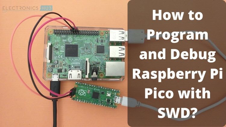
A complete tutorial on programming and debugging Raspberry Pi Pico using SWD Interface. Learn how to Program Raspberry Pi Pico with SWD.
sly sand
thanks 🙂
 iron fable
I've attended this as a guest a few times and its super fun. You all should create something fun and enter! Its in San Francisco. https://www.dnalounge.com/calendar/2021/11-14.html

Do you like ROBOTS? And DRINKING? Experience incredible
robot bartenders serving you drinks, lovingly crafted with MAD
SCIENCE by the finest competitors in the art of robotics and
bartending. You probably won't get wet. Probably. Or disassembled.
Probably. Spectators and Victims: Admission includes two robot drink
chips to spend at any cock...
And oh look, Peristaltic pumps are even in stock https://www.adafruit.com/product/3910
Move fluid safely from here to there with this very nice Peristaltic Pump that works with 5V or 6V power. Unlike most liquid pumps, this is a peristaltic type - the pump squishes the ...
wraith flame
Haven't been able to find NeoPixel Strands in the fritizing library. Do folks just use NeoPixel strips?
 spiral coyote
has anyone ever worked with a portable lipo charger before?

these ones?
i'm trying to charge a 11.1v lipo with 3 cells, but whenever i tried to do so, it will always reset itself. No alarms, no warnings, it just goes back to the selection screen
does anyone know what's up?
this problem doesn't happen with my other lipo batteries
primal shell
It could be your power supply isn't up to the task
 ruby gust

Udemy
Learn Arduino by building a 3d printed Iron Man Arm with Voice Recognition, Accelerometer, Sounds, and more electronic
 smoky zealot
I am considering a LIDAR for my next project which will be a small robot for in house movements only. Any suggestions on a reasonably priced LIDAR?
lone skiff
smoky zealot
I am considering a LIDAR for my next project which will be a small robot for in ...
Apparently the Neato vacuum cleaners have a relatively cheap lidar unit that people have hacked for other uses. It looks like spare ones are available separately.
 storm ore
I am trying to drive 3 4V DC motors using Metro+Adafruit motor shield v2. Can I plug 12 V AC, 1.2 Amp wall wart to Metro (or is 12 V DC the way to go) ? Or might it be preferable to split up the power supply for the Metro and Motorshield?
 idle valve
storm ore
I am trying to drive 3 4V DC motors using Metro+Adafruit motor shield v2. Can I ...
idle valve
storm ore
I am trying to drive 3 4V DC motors using Metro+Adafruit motor shield v2. Can I ...
It's preferable to split the power supplies, but both will require DC
vagrant thunder
Metro boards accept up to 9V, last I checked.
You don't need 12V for 3 motors, you need a ~4V supply that can handle the current draw the motors are going to require.
I think the motor shield has a minimum of 4.5V though
idle valve
You can always run it at ~80% throttle, though.
hm
Yeah, says "Can run motors on 4.5VDC to 13.5VDC"
storm ore
Thank you!
 torpid garnet
How can i reduce the voltage in a circuit that uses AA batteries?? Trying to make a DC motor spin slowly
idle valve
torpid garnet
How can i reduce the voltage in a circuit that uses AA batteries?? Trying to mak...
Is this circuit a super simple one - That is, just the batteries and the motor?
torpid garnet
yup! well, and an on off switch

EUDAX 6 set Rectangular Mini Electric 1.5-3V 24000RPM DC Motor with 84 Pcs Plastic Gears,Electronic wire, 2 x AA Battery Holder ,Boat Rocker Switch,Shaft Propeller for DIY Science Projects
i bought this cuz i'm new to electronics and don't know what i'm doing
idle valve
torpid garnet
i bought this cuz i'm new to electronics and don't know what i'm doing
These sorts of kits are fantastic for that
torpid garnet
uh oh is that sarcasm?
idle valve
No, enthusiasm!
idle valve
I genuinely love these sorts of kits since you can just. Do whatever with them
torpid garnet
Yeah. Now i just need to know how to do stuff
idle valve
So what's your goal with making the motor spin slower - Do you want it to spin slower at a set speed, or do you want to vary the speed?
torpid garnet
How would i do either? Variable means using a potentiometer right?
idle valve
torpid garnet
How would i do either? Variable means using a potentiometer right?
There's a lot of ways to do it, but yeah, I was thinking some sort of pot for variable
For a set speed, you could figure out something with those gears it comes with. Generally this will get you better performance - A higher torque for the same amount of power, at the cost of RPM
If you reduce the voltage, it'll spin slower, but also reduces the amount of power to it (For obvious reasons), and depending on the motor you'll reach a power setting where it won't spin because it can't get going.
torpid garnet
ahhhhh Good to know
with what i saw online i tried throwing 2 resistors on a circuit and it didn't do anything
idle valve
I don't fully understand how resistors work, and there's several ways you could do it. A voltage divider is one of them, but putting them in-line has to have specific settings depending on power consumption and that's beyond what I've ever needed. Largely because there's other ways to do it
For fiddling around at first? I'd recommend some potentiates like these: https://www.amazon.com/gp/product/B01DKCUVMQ

uxcell 5 Pcs 10K OHM Linear Taper Rotary Potentiometer 10KB B10K Pot Zinc Plating with 13mm Shaft
And possibly a solderless breadboard so you can pop things in and out really easily. Super useful for testing things and the like
torpid garnet
Sounds good. Appreciate the advice
idle valve
Once you want to get into programmable stuff like microcontrollers, breadboards are super useful as well.
idle valve
Yes!
They have your voltage, your ground, and the "output"
In most cases, the pot is read by a microcontroller or some other doodad, but for a simple thing like this, it's just fine.
For those in particular, the voltage in/ground are the outer pins (It doesn't really matter which is which) and the output is the center pin.
torpid garnet
ahhh so it completes a circuit and then bleeds out the energy through the output as you turn it?
idle valve
It's effectively a variable resistor. I'm not 100% sure on the physics or such behind it
torpid garnet
In my head ground is like the safety for household electronics. but for this is ground the wire returning to the batteries?
idle valve
Unless I'm completely dropping the ball on if this is a good idea, here's how I would wire it:
Battery positive to one side of the potentiometer
Battery negative to the other side of the potentiometer, and also to one side of the motor
Middle pin of the potentiometer to the other pin of the motor
torpid garnet
Seems good to me
If i turn the potentiometer so that the motor is off, are the batteries still losing power?
idle valve
maybe. But it shouldn't be a direct short.
You can turn it to where the motor doesn't make any noise, but it still might be passing through the motor just a wee bit.
I'm actually heading out for a bit now, so I'll be back later. Feel free to keep posting questions, though, there's plenty of knowledgeable people around. Most of them know more than me, too!
torpid garnet
Thank you very much i appreciate the help
vagrant thunder
torpid garnet
If i turn the potentiometer so that the motor is off, are the batteries still lo...
Technically, the battery will never completely turn off in this configuration, so you should still include the power switch. The current will always flow from the positive end through the motor to ground, and adjusting the pot will limit the current that flows through the motor. At its lowest, the current flowing through the motor will not even be enough to turn the little spindle, but the resistance from the potentiometer will continue to draw current and consume battery.
torpid garnet
Good to know thank you
pine bramble
Generally it’s better to pulse width modulate (PWM) a motor rather than simply vary its voltage, as a DC motor doesn’t react to voltage changes anywhere near as consistently as via PWM, which is also more efficient and both hardware and programmatically simpler.
I.e. you won’t get linear response with PWM but closer than a potentiometer.
Also, with PWM when the motor controller is set to zero there will be no battery loss through the motors.
torpid garnet
Nice. They look simple enough too
 round bough
Hi to community,
First of all I want to appreciate Adafurit for such incredible products and libraries, and a special thanks for Adafruit AHRS Kalman library, implementing the original NXP library is a nightmare. I have been working with IMUs for a long time, and I used Adafruit BNO055 and Adafruit LSM9DS1 and lots of other sensor boards in my previous projects. I think the BNO sensor is a masterpiece but as you know you don't have access to source code nor matrices, so there is no possibility to manipulate the output. Having manipulation limitations on BNO I decided to use LSM9DS1, Now that I'm using it with the Adafruit AHRS library, the results are outstanding. Comparing BNO and LSM9DS1 outputs, LSM is a little bit shaky and unstable, so I decided to make some adjustments in library definitions, for example various noise constants and filter frequency, I also tried different ODR and FS setting on sensor but it had no noticeable effect. So I decided to ask to community,
What exact setting should be set for sensor?
Which frequency should I run the filter?
What should I do rather than above ones to get perfect and smooth output like BNO?
I will be happy for any advice from another perspectives too.
And your more than welcome to ask relative questions.
Best Regards,
Mason
sly sand
I can't answer but what do you mean by can't manipulate the output ? Like you don't know the noise function and you can't kalman filter it ? Otherwise BNO055 seems very interesting
round bough
sly sand
I can't answer but what do you mean by can't manipulate the output ? Like you do...
bno has onboard cpu and memory which programmed to give you nice outputs, but you cant edit some important stuff like matrices
 idle grove
Can I use a Xbox one controller to control a robot running Ubuntu wirelessly
lone skiff
Yes, with appropriate hardware and software.
torpid garnet
How do i know which way to read a resistor???
 forest cipher
steel lintel
forest cipher
steel lintel
The tolerance bars are always on the right
 torpid garnet
But for the 5 band one on that example what if it was flipped around?
red can still be read as a tolerance
steel lintel
Hmm... Actually, I've never seen red for tolerance...
Oh, yeah, bands 1-3 are bunched up on the one end
steel lintel
No problem!
sly sand
My university used to have a bunch of self-serve free resistances boxes. Had a lot of fun taking a couple and running away to see who was new in the dept 😄
steel lintel
Lol
torpid garnet
Anyone know a beginner project i should work on to learn electronics and soldering?? i'm completely new to it
steel lintel
There are kits that can teach you both

Elenco AmeriKit Learn to Solder Kit
Oop, long link... But anyway, kits like that start going over electronic basics and are good soldering practice
Although I would check you Adafruit YouTube channel for videos about electronics in general
round bough
round bough
Hi to community,
First of all I want to appreciate Adafurit for such incredible ...
such a wow robotic topic
pine bramble
round bough
Hi to community,
First of all I want to appreciate Adafurit for such incredible ...
Have you considered "fusion" across two different (deliberately different model) IMUs? I've found the BNO055 and say, the ICM20948 to have different characteristics and have been playing with fusing the heading across both. So rather than try for perfection with a single IMU, how about two?
round bough
pine bramble
Have you considered "fusion" across two different (deliberately different model)...
that's not the point
pine bramble
round bough
that's not the point
I wasn't addressing your point, I was asking a question.
round bough
pine bramble
I wasn't addressing your point, I was asking a question.
there is no limitation in using different imus
you can even use separate breakout boards for gyro acc and ma
mag
but you have to consider imu axis conventions
pine bramble
Yes, understood. In your description of what you've been doing you mentioned the black box nature of the BNO055, and I was simply wondering if you've tried using a second, different, IMU in order to be able to compare the two, as a form of "fusion".
round bough
pine bramble
Yes, understood. In your description of what you've been doing you mentioned the...
.
round bough
pine bramble
Yes, understood. In your description of what you've been doing you mentioned the...
its all about fusion algorithm
pine bramble
round bough
sure I did
To be clear, I don't mean comparing them as products on the bench, I mean comparing them live, as in the two running at the same time, with a summing/fusion algorithm.
round bough
pine bramble
To be clear, I don't mean comparing them as products on the bench, I mean compar...
Sure
I tried all of them with different calibration, fusion , frequency and ....
pine bramble
...then you must have by now come to some conclusions on what works for you?
On my robots I and many of the Dallas Personal Robotics Group (DPRG) seem to have settled on the BNO055 or BNO085, though others have been handy as well.
round bough
pine bramble
...then you must have by now come to some conclusions on what works for you?
O...
Its all about price
BNO sensors are great but expensive and as you said its a black box
and I think using lsm9ds1 which I have it on my arduino nano board is more logical
the whole board costs about 30 usd
Just a bno sensor costs more than that
pine bramble
Well, I have about a dozen IMUs of various kinds that I've experimented with, and several BNO055s. The newer Stemma versions are cheaper now, US$20 or so, and I don't have a requirement for more than one per robot, and a robot costs easily $800-1000. So the IMU cost isn't really all that significant. But for smaller projects a BNO055 is probably overkill, especially if one isn't using all 9 DoF.
smoky zealot
I was considering controlling 12 servos using Stemma motor driver boards. Are multi-channel Stemma driver boards available? Any suggestions?
pine bramble
smoky zealot
I was considering controlling 12 servos using Stemma motor driver boards. Are mu...
Stemma is just the connector, it's actually using I2C protocol, so the big question is how many servos are handled by a servo driver board and if the I2C address of the board can be modified (often by a solder jumper) to permit multiple boards. Adafruit has a number of servo controllers, one a 16 channel (i.e., 16 servo) board for the Raspberry Pi (among others): https://www.adafruit.com/product/2327
The Raspberry Pi is a wonderful little computer, but one thing it isn't very good at is controlling DC Servo Motors - these motors need very specific and repetitive timing pulses to set ...
smoky zealot
Thanks @pine bramble for the clarification and suggestions
pine bramble
smoky zealot
Thanks <@828135237744984114> for the clarification and suggestions
You're very welcome. I'm just digging around on how to use interrupts with the Pimoroni IO Expander, their little 4051-powered Breakout Garden board. I'm using it as the main digital and analog connection between my "Integrated Front Sensor" (a bunch of analog and digital IO pins) and a single I2C connection. Basically, if you include power and ground, a four wire connection to the entire front array of sensors on my robot: 5 analog IRs, 3 pairs of lever switches for my bumper, and a pair of analog light sensors for the moth behaviour. That whole assembly can be moved between the KR01 and KD01 with just that single connector and two 5mm bolts. What I'm thinking is to add an additional wire to push an interrupt and callback onto one of the Pi's GPIO pins so the bumpers don't need to be polled.
smoky zealot
I am looking at the BNO055 Stemma QT based product, I read about it’s capabilities to provide outputs such as absolute orientation (Euler vector and quaterian), acceleration vector and others, need to better understand what these are and how to use them in a robot control system. If anyone is aware of any reading resources, can you point me to them? Is this device better suited for quadcopters or can it also be used in ground based robot control systems?
Are there any tutorial type resources for the above?
pine bramble
Regarding IMUs:
- MatLab: Understanding Sensor Fusion and Tracking, Part 1: What Is Sensor Fusion?
https://youtu.be/6qV3YjFppuc - MatLab: Understanding Sensor Fusion and Tracking, Part 2: Fusing a Mag, Accel, & Gyro Estimate
https://youtu.be/0rlvvYgmTvI - MatLab: Understanding Sensor Fusion and Tracking, Part 3: Fusing a GPS and IMU to Estimate Pose
https://youtu.be/hN8dL55rP5I
 fresh crown
👍
they have a useful PID controller discussion too
 tardy isle
ok quick question, if I have a servos connected to a voltage regulator which is connected to a battery, and I wanted to power a raspberry pi off of the same battery, can I connect a UBEC to the voltage regulator to bring the voltage down even more?
primal shell
Sure, but it's likely more efficient to connect the UBEC to the battery instead.
tardy isle
ok thanks!
 nimble root
Worth mentioning that servos are usually fairly tolerant of somewhat higher voltages. Tower specs their servo speeds at both 6V and 4.8V. Servos might not even need to be on regulated voltage, though it might make speed / distance more repeatable. It’s also nice if the servos stall and draw more than your regulator max but less than the battery pack max.
 pine bramble
round bough
Is there anyone helping me with these mystery numbers?
pine bramble
round bough
Is there anyone helping me with these mystery numbers?
You've showed what look like a bunch of defined IMU constants but not said anything about what kind of help you need, what your problem is, why you'd want to change them or why they're a problem, so I don't assume anyone would know what help you want...
 abstract totem
round bough
Is there anyone helping me with these mystery numbers?
abstract totem
round bough
Is there anyone helping me with these mystery numbers?
Without knowing where the source code came from, it looks like it's a collection of constants for the kalman filter. They help the filter understand the boundaries of what the sensor's values can actually mean--for example the noise needs to be modeled because every sensor has a certain level of noise. Including that into your calculation helps the filter understand that the imu isn't fluttering everywhere when the levels are close the the noise levels.
native cipher
long ago I decided that kalman filter is black magic, best left to professionals - I might use a library that has it, but I am not qualified to make any changes or fine-tune any parameters...
abstract totem
native cipher
long ago I decided that kalman filter is black magic, best left to professionals...
Now I'm wondering how easy it would be to build a jupyter notebook to help with tuning the parameters...
sly sand
Hey folks, I built this little robot arm kit, but my kit didn't come with the arduino shield with potentiometers. Can I use the arm using only the arduino? If so, any tips on how to do so?
 lone skiff
Without potentiometers you wouldn't have a manual way to control it, but you could still script motions in code, for example.
sly sand
Yeah that was what I was hoping to do
I'm very noob though. I will have to look up how to wire this to the board

all the servos have these 3 pin connectors on them. I think I will need to use the cables I used for breadboards to connect it all up
or use a breadboard beside the arm to make life easier
since I would assume the potentiometer arduino shield was made for just plugging the servos in directly
idle valve
@sly sand You'll need to supply a PWM signal to the servos, and also +5v and Ground. I wouldn't recommend pulling off of the Arduino's 5v though, it's not designed for that much current.
The Uno has... 6 PWM channels, though? So there should be enough to control the arm as long as you supply power to the servos
sly sand
Ok! I watched a very helpful video just now. I will power using bench power supply and then one of those 6 PWN channels. Its alive!!
(using servo tester hehe)
DroneBot Workshop video on using servos was very helpful
idle valve
Excellent! I've used Adafruit's PWM/Servo thingamajig before and really like it, and it comes in Shield form:
https://www.adafruit.com/product/1411

You want to make a cool Arduino robot, maybe a hexapod walker, or maybe just a piece of art with a lot of moving parts. Or maybe you want to drive a lot of LEDs with precise PWM output. Then ...
sly sand
Oooh ok I'll check it out now, thanks!! 🙂
 willow geyser
idle valve
Excellent! I've used Adafruit's PWM/Servo thingamajig before and really like it,...
willow geyser
idle valve
Excellent! I've used Adafruit's PWM/Servo thingamajig before and really like it,...
I'm currently having an issue with that product. For some reason the PCA chip becomes unstable when VCC is 3V3 and v+ is 5V
idle valve
willow geyser
I'm currently having an issue with that product. For some reason the PCA chip b...
That's interesting, because I'm pretty sure that's how I'm using it. I've got the Motor Wing, which uses the same chip with some extra hardware. Also have the standalone breakout but haven't fiddled too much with that recently.
You're using the shield version?
willow geyser
idle valve
That's interesting, because I'm pretty sure that's how I'm using it. I've got th...
I'm using the PCA9685 breakout. connected to jetson nano. 3V from jetson to VCC and 5V from jetson to v+
when VCC = V+ = 3V the pwm signal and i2c is great. But when VCC = 3V and V+ = 5V the PWM signal seems 1.7V and i2c is not stable.
idle valve
Hm. The thing that immediately comes to mind is the Jetson Nano's 5v might have some. Funky stuff going on. Have you tried with an external 5v source?
When I get on my PC I'll be able to look and see what sort of circuitry differences there are between chips, but that'll be a few minutes
willow geyser
idle valve
Hm. The thing that immediately comes to mind is the Jetson Nano's 5v might have ...
I have not yet tried a seperate source, since I have jetson connected to a 25W DC to DC 5V from 48V converter.
and Jetson should be able to source 2.5A from each 5V pin
but I am not driving a servo, just need the 5v PWM for external controller
And yes, thank you , i am patiently waiting for your results 🙂
idle valve
willow geyser
I have not yet tried a seperate source, since I have jetson connected to a 25W D...
I'd try it, just to eliminate the possibility. Honestly I don't think it's likely, but I've had some weird results with things before.
willow geyser
i think you are right, i will try to get 5v before the jetson
willow geyser
idle valve
I'd try it, just to eliminate the possibility. Honestly I don't think it's likel...
So, i put the 5V before the jetson into the PCA using the V+ screw header. I only have VCC connected to jetson along with GND and SCL and SDA,, for some reason it seems like the PCA board is feeding V+ into VCC because the jetson only boots when VCC is not connected.
idle valve
That's. Weird. I'm not familiar with the Jetson, so I can't exactly say what's going on with that
willow geyser
it's the PCA i am sure, i am looking for the problem
yes, VCC is connected to v+ maybe i shorted?
idle valve
that sounds possible
@willow geyser Just to confirm, this is the product you're using: https://www.adafruit.com/product/815

You want to make a cool robot, maybe a hexapod walker, or maybe just a piece of art with a lot of moving parts. Or maybe you want to drive a lot of LEDs with precise PWM output. Then you ...
?
willow geyser
Yes and I confirmed they were shorter somehow , trying different board now
idle valve
OK, so. The PWM output is always going to be what the chip itself is supplied with. There's no method for it to adjust this - No transistors, mosfets, etc, on this board. It's designed for servos, which have a ground, voltage in, and PWM input. And most hobby servos don't care too much about what voltage that PWM signal is going to be at.
That said, V+ should definitely be separate from VCC, and any connection is going to be a short somewhere.
What are you trying to use the board for?
willow geyser
Hey @idle valve v+ is not attached to VCC so I am able to use the 3v3 logic and a 5v output. However, I wonder if there is a grounding issue? Just using the dc supply to power the system and my scope looks like this

Doesn't seem normal to me, what could be issue?
primal shell
Looks like a ground loop: you can get that if the two power supplies are plugged into different outlets and their ground references aren't connected to each other.
willow geyser
Ahh, it is in series. I will check ground, thank you very much!
willow geyser

@primal shell am I missing something , not sure why this would he floating
or have a ground loop
primal shell
I don't see enough of your setup to say. Normally there's a logic supply and a motor supply.
willow geyser
I have 48V from supply, to a dc step-down to 5v for logic , to power jetson nano which powers the pca9685
The 48v powers the motors and controllers
But the scope is refecend to negative on the step down for Gnd ref, and pwm 0 for positive ref
primal shell
Is the step-down an isolated one?
willow geyser

@primal shell how can I tell if it is isolated ?
And what would that mean? Do I need to add another path to ground after the step down?
primal shell
It would mean the ground wire for the input isn't connected to the ground wire for the output. You could try connecting them.
 willow geyser
@primal shell sorry to bother you again, but seems like I ran into another issue. If I have connected the DC step down output negative to the input negative, then both logic and motor ground is connected and should be stable , I even connected Ground of jetson again to main ground, but this ground still floats?
 primal shell
I'm still not clear on your overall setup. What are you measuring there?
willow geyser
Gnd ref is pca9685 gnd and v+
Also jetson gnd ref, and pca9685 vcc
Maybe I am chasing ghost in machine it goes from. Normal to crazy


More concerning, is why pwm signal is 3.4V and not 5v
sly sand
Someone in your house captured your screen and is photoshopping you
willow geyser
no, that is me
ok, this is my setup again.
48V - DC step down 5V -> USB C adapter -> Jetson Nano -> PCA9685 -> V+ (5V) VCC(3V3) , GND to GND, GND is common between the input to the Step down regulator to the output of the regulator. When I measure with my Oscope with the GND ref of the Regulator output Negative, the Scope is stable when measuring PWM out of PCA; when I use the GND on the PCA as ref to the PWM out of the PCA, the scope is not stable.
multimeter continuty says all gnd are common
but this won't drive my motor controller. 😦
sly sand
back of the envelope hand-drawn schematic was posted where ;)
primal shell
I'm impressed the motor yielded a scope trace like that, but still, good job figuring it out!
willow geyser
To confirm, this statement means to place the resistor between the signal output and the hall sensor + ref (5v) ?
 willow geyser
seems not needed, i scope proper signal without
primal shell
It sounds like the sensor has an "open collector" output (on some motors), and those would need a pull-up resistor to operate reliably. Some Hall sensors have a logic output and would not need a pull-up resistor.
 cursive helm
I suspect they tell you to use the pull-up for a reason...As noted, it may not be reliable without it. It does say "The speed pulse output is OC" .
willow geyser
perhaps, need to run it through logic level converter to be useful, will test it shortly.
primal shell
An advantage to open collector outputs is that you can often pull them up to whatever logic level you need, so you don't need a level shifter.
willow geyser
It is a 5V pulse signal
primal shell
If it's open collector, it would be whatever level the resistor pulls it up to.
willow geyser
why do i get 5v signal with no resistor?
primal shell
That I do not know.
 desert orchid
if the resistors there to handle electrical interference on your lines and it is occurring without it could be something to do with how the servo handles power that the resistor helps enough to prevent from occuring
idk what your systems like, but I have seen people with badly planned and positioned coils in their projects that jammed up the works as well, don't think its that at all XD just that it will definitely be the last thing you realize..
willow geyser
anyone know of a power sensor (voltage is priority) for 48V? the one on the adafruit site seems only for 36V.
primal shell
Do you just want to detect the presence of voltage or actually measure power or what?
willow geyser
voltage for battery level is requirement, other features are useful but not required.
primal shell
A resistive voltage divider might be sufficient in that case.
willow geyser
wish it was on breakout board 😉
primal shell
You want a voltage divider on a breakout board?
willow geyser
i found what I need from "other" company
willow geyser
hey smart people, please help me understand this.... I have 2 identical motors, identical motor controllers, identical wiring. One motor operates perfectly on PWM or manual potentiometer mode. The second motor operates normally on manual mode but on PWM mode has 1/2 the power and uses 2X the current (no load) as the first motor. Both PWM signals are on the PCA9685 breakout. The settings on the motor controllers seem the same. Any idea what I am missing? or should check?
vagrant thunder
Confirmed an issue on the motor? What kind of motor?
Have you switched the motor/controllers around?
primal shell
I haven't tried using PWM on BLDC motors, that's more for DC and stepper motors in my experience.
willow geyser
the motor controller accepts PWM signal
swapping motor controllers shows that one motor is still normal both methods , and the other motor is not working as expected with 2x current draw and power loss
so i assume motor is issue, but do they go bad in storage?
or could hall wires be different?
not hall wires. hmm
vagrant thunder
Could be a stray capacitance in the faulty motor? That's all I can think of as far as PWM issues go...
willow geyser
i get the same issue with the motor even with the POT
vagrant thunder
Oh, I thought manual mode was the same
Hmmmm
Can you measure the resistance across the motor leads?
willow geyser
i can measure resistance into the controller? or there are 3 wires that go from controller to motor power?
red, yellow, black
vagrant thunder
Can you send me the part number for the motor in question?
I may have assumed all motors had a ground wire of some sort.
willow geyser
this is the motor: https://www.dropbox.com/s/cqoqtw00ytl6rxe/GearMotor_ForWheel.pdf?dl=0

this is the controller https://www.dropbox.com/s/sla6oqd6u4f2p8y/Motor_Controller.pdf?dl=0
the multimeter seems to jump around for resistance on the black to red
willow geyser
riddle me this other question please....... why would PWM mode get less output then manual POT mode?
vagrant thunder
The controller looks like it's using an ADC to read the desired speed, so if it's something on the controller side, it could be a bad PWM-to-analog filter inside the controller. However, if the Potentiometer is exhibiting the same issues with the same motor in both modes, I would not be questioning the controller.
pine bramble
willow geyser
hey smart people, please help me understand this.... I have 2 identical motors,...
Is one motor rotating the opposite direction of the other one?
willow geyser
pine bramble
Is one motor rotating the opposite direction of the other one?
only if I don't use F/R pins
pine bramble
willow geyser
only if I don't use F/R pins
I was just pointing out that DC motors have very different characteristics when running clockwise vs. counterclockwise, some more than others.
willow geyser
pine bramble
I was just pointing out that DC motors have very different characteristics when ...
Yes, for some reason I am technically running on in clockwise and the other counterclockwise but they seem fine going forward, a little shake in reverse. But that is still rotation counter to each other since they are for a differential drive robot
pine bramble
willow geyser
Yes, for some reason I am technically running on in clockwise and the other coun...
Yes, my own experience is with differential drive robots. If you're testing for performance or current usage you might try running them the same direction, even if that means putting your robot on a bench so it doesn't spin in place. As I said, DC motors perform quite differently forwards vs reverse.
primal shell
Even BLDC?
willow geyser
pine bramble
Yes, my own experience is with differential drive robots. If you're testing for ...
I'm pretty sure the one motor that runs in the opposite direction it goes bad
pine bramble
willow geyser
I'm pretty sure the one motor that runs in the opposite direction it goes bad
Swap the motors and see if it's the same.
willow geyser
It is the same
pine bramble
willow geyser
It is the same
Then that would suggest it's not a problem with an individual motor but an artifact of one rotating clockwise, the other counter-clockwise.
willow geyser
pine bramble
Then that would suggest it's not a problem with an individual motor but an artif...
💯 agree
pine bramble
willow geyser
💯 agree
This is one good reason to run with closed-loop control (using motor encoders and a PID controller), so that one can precisely set the velocity of each motor, otherwise it's impossible to drive in a straight line (or know how far the robot has gone).
willow geyser
pine bramble
This is one good reason to run with closed-loop control (using motor encoders an...
Yes, I have that. My issue is quality. Motor quality degrades too quickly in the counter direction
pine bramble
By quality do you mean motor speed vs energy input? Wouldn't closed-loop control solve that by automatically increasing or decreasing the PWM of the motors so they were operating as per target velocity?
willow geyser
pine bramble
By quality do you mean motor speed vs energy input? Wouldn't closed-loop control...
By quality, I mean motor failure, it degrades and pulls 2x current with 1/2 motor power when run in the counter direction for some specific amount of time
Stops working
pine bramble
willow geyser
By quality, I mean motor failure, it degrades and pulls 2x current with 1/2 mo...
What kind of motors are you using? And how old are they? Possibly damaged?
willow geyser
pine bramble
What kind of motors are you using? And how old are they? Possibly damaged?
Technically unused, been in storage for a year due to covid. Brushless gear motor
pine bramble
Have they operated okay in the past? Or is this your first try using them? In other words, can you rule out a problem with the motors themselves and assume it's the controllers? It sounds like the problem is only in the counter direction, which suggests either a problem with the motor controller or in the way you're using the software to control them.
In any case, I'm off to bed (late here). Good luck!
willow geyser
Wonder if I switch the polarity of the bldc and hall sensor maybe that will fix it?
primal shell
It could be a phasing problem, I'm unsure what you mean by polarity here: the hall sensors are unipolar, and the motor windings are in a delta configuration. However, you could try swapping two of the motor drive wires.
willow geyser
primal shell
It could be a phasing problem, I'm unsure what you mean by polarity here: the h...
Maybe drivers are mismatch to the motors? I am going to try new drivers when they arrive on Thursday
 supple moon
I don’t understand why a motor running in reverse would perform differently. Other than a technical explanation, my experience in first robotics has been that they run the same.
 finite yew
Hi all. I think there may be something fundamental I'm missing here. I'm trying to drive a 5-6V medium solenoid, specifically https://www.adafruit.com/product/3992.
The idea was to drive it with an H bridge IC, powered via 5V from the USB pin of a feather, with the 5V input coming from a powerboost (to boost the lipo up to 5.2ishV. I have been able to drive it by hand for a fraction of a second by hooking it up directly to the power, but no luck when using the hbridge.
Here is a simple drawing of my circuit

I have verified that putting in a led between OA and OB of the hbridge does light up when I go to trigger it.
does anyone have any ideas? the trigger code is only pulsing IA for a very short amount of time since I know the solenoid takes a lot of current (And I only need it to kick on/off anyway, I don't need to hold position)
pine bramble
supple moon
I don’t understand why a motor running in reverse would perform differently. Oth...
Are you running PID controllers in First Robotics?
supple moon
pine bramble
Are you running PID controllers in First Robotics?
Often. But even without and a simple differential drive train 1/2 the motors run backward. Never any issues. You might get slight drift, but that is per motor difference, not a forward/reverse thing.
pine bramble
Brushed DC motors have different physical characteristics in each direction. You may not have noticed it or perhaps the motors you were using didn’t differ below the threshold that other factors masked them.
PID controllers would entirely eliminate the problem.
primal shell
finite yew
does anyone have any ideas? the trigger code is only pulsing IA for a very short...
It looks like you aren't driving the IA input
finite yew
IA is connected to D9, and I'm output-ing HIGH from D9 when I want to activate the solenoid. I am not driving IB though, I didn't think I needed to since It's just a solenoid and direction shouldn't matter?
I've also tried wiring OA to 1 wire of the solenoid, with the other solenoid wire to ground. (instead of using both OA and OB). The product page for this H bridge said I could drive 2 solenoids, so I assume to do that one would be on OA and the other on OB. I only have 1, though.
vagrant thunder
finite yew
does anyone have any ideas? the trigger code is only pulsing IA for a very short...
Is your hbridge ic rated for the current the solenoid is trying to draw?
finite yew
vagrant thunder
Is your hbridge ic rated for the current the solenoid is trying to draw?
It should be, is only supposed to draw 0.8A at 5V. I think i figured out the "why" but now I'm not sure on the best fix. It seems the voltage output from the h bridge is only about 4.6V, not enough to activate. This is further proven by it being able to hold position if I manually move it while activating the h bridge, and de actuates once i remove power to it.
So it seems to work if I manually pulse it 5V by touching the wire to the 5V out of the power boost. So I need another way to control it that doesn't drop as much voltage? I've seen MOSFETs and diodes being used, but i thought and h bridge is pretty much the same thing, but in IC form. Or somehow boost the power more?
primal shell
An H bridge is only needed if you want bidirectional motion: most solenoids just pull one way and are either passive or have a spring return the other way. To just pull one way, a simple transistor works well.
Note that you'll also want a protection diode, as with any inductive load.
finite yew
Yea, I just thought it would be a more convenient package.
Run two solenoids, or a single DC motor with up to 800mA per channel using the super-simple L9110H H-bridge driver. This bridge chip is an 8 DIP package so it's easy to fit onto any ...
vagrant thunder
Just to be sure, you're using a powerboost 1000?
finite yew
Yea
vagrant thunder
Okay, then it's most likely the voltage drop through the bridge chip.
The bridge seems to output around 7.6 volts when supplied with 9V. I anticipate your circuit is probably also experiencing a similar drop of either 1 or 1.4V?
You may have to use a higher supply voltage to utilize this driver.
Usually something like this works much better, and its form factor isn't terrible either. https://www.adafruit.com/product/976

Transistors are powerful little electronic switches, and when our little NPN transistors aren't power enough for your project, we have been known to use these beefy TIP120 Darlington ...
vagrant thunder
No.
Actually, wait a minute
Yeah, you'll probably need your own protection diode. I don't think the H-bridge had diode protection either, though....
vagrant thunder
Uhhhh, @primal shell Protection diodes are routed parallel and reverse direction of the device in question?
primal shell
That's a usual configuration, but there are other possibilities.
smoky zealot
https://www.adafruit.com/product/4010 - Before I use the RPLIDAR A1M8 with an embedded device, I wanted to check it out with the RoboStudio on Windows10. I am able to recognize the device on the COM port as seen in Windows Device Manager, but am not able to connect it to RoboStudio application. Can anyone help with suggestions or pointers?

Is your favorite robot currently in a mid-life crisis? Does it need a new purpose or perhaps, direction? Well now you can find your way with the affordable and easy to use Slamtec ...
smoky zealot
I was able to figure this out. By using framegrabber from the SDK rather than RoboStudio, it worked
 cinder gust
anyone active here that can teach me something? I just started and Im having problems with a capacitor lol
lone skiff
cinder gust
anyone active here that can teach me something? I just started and Im having pro...
The rule of thumb is to just ask your question, rather than asking for a volunteer to answer it before they know what it is.
fresh crown
not knowing whats up, I can randomly say that I know a few capacitor types hate getting negative voltage
pine bramble
not knowing what's up, I'm not sure a capacitor issue has anything to do with robotics... 🤔
fresh crown
I have one of those cheapo pivoting ip camera thingies that seems to cause an undervolt during early start (and thus a startup loop), I'm guessing due to the motors. once I rule out the powersupply as a problem I'll look loosely in the direction of capacitors
pine bramble
fresh crown
I have one of those cheapo pivoting ip camera thingies that seems to cause an un...
Is there a way to power it up after things have stabilised? Like with a MOSFET switch or something? A capacitor isn't probably going to help that much, i.e., it's not a silver bullet.
Or isolate the power supplies for your non-computer bits.
fresh crown
eh, it is a product I have not opened yet, the part that undervolts is whatever onboard controller it has, I'll have to open it for more info, but as a function of laziness that may be a half year from now
primal shell
It's possible that a big capacitor might not help: if the power supply is shutting down due to overcurrent, it might do the same thing charging the capacitor. It's worth a try, however. If it has trouble with that, you can wait for it to charge the capacitor a pulse at a time, or add a soft start circuit that charges the capacitor through a current limiting resistor.
 indigo echo
I have a Adafruit Feather 32u4 Bluefruit LE with a DC Motor + Stepper FeatherWing. A couple of weeks ago i got the motor and stepper working and still trying to figure out how to connect to the bluefruit. I connected to the feather today and got the following error message.
processing.app.debug.runnerexception
at cc.arduino.packages.uploaders.SerialUploader.uploadUsingPreferences(SerialUploader.java;152)
at cc.arduion.UploaderUtils.upload(UploaderUtile.java:77
And it goes on. Can anyone give me some suggestion on where to look to fix the problem.
primal shell
The first few lines tell where it's happening, the last few lines (hopefully) tell what is happening, which is likely the important bit.
indigo echo
primal shell
The first few lines tell where it's happening, the last few lines (hopefully) te...
It looks like i have a Caused by ---Serial Exception; Error touching serial port 'Com 3'
And a Caused by jssc.serialportexception; Port name - COM3' Exception type - Port busy.
Looks like i need to reboot and try again.
primal shell
Possibly, it seems to think something else is using that port.
 oak ingot
Hi folks, I need a little help selecting a motor driver. I'm planning a small 3-wheel car (running just 2 motors) and of course I'll use PWM to control the motor speed. I've narrowed it down to two Adafruit breakout boards with either the TB6612 or DRV8833 driver. I think either will work fine for my power needs, but the confusing bit is in the wiring for PWM... The TB6612 has dedicated PWM inputs for each H-bridge, whereas the DRV8833 does not and will take PWM as the input signal, which makes perfect sense to me (as far as my understanding of how the H-bridge works)... So can anybody explain why the TB6612 board has a separate input for PWM?
native cipher
tb6612 uses for every motor a pwm signal and two additional signals to set direction/braking; they are not pwm - they only indicate direction. It can be benefitial when you have plenty of digital pins but few pwm pins
but yes, I also find two pwm inputs like drv8833 uses more natural
oak ingot
Thanks @native cipher ! That makes sense, and it's good to know that it's just a design decision rather than a behavioral difference.
 unreal sorrel
I have a project that requires two 35kg servos with an operation voltage of 7.4v, what is the best way to power these servos via like a wall outlet? It will always be connected to power and will need to run every night for probably 5 hours or so, I did something similar last year with smaller servos but was trying to power them directly from an arduino uno so they cut out pretty often and had to have a separate uno for each servo. Ideally I will be able to control both servos via one arduino and have them powered externally so I don't have to worry about it dropping out or anything. Just wondering what my best option is for power.
native cipher
get a power adapter like this:
YUNBO AC 100-240V to DC 3-12V 5A 60W Universal Adjustable Power Supply Adapter for LED Strip lights https://www.amazon.com/dp/B07K1LV2CM/

YUNBO AC 100-240V to DC 3-12V 5A 60W Universal Adjustable Power Supply Adapter for LED Strip lights
(I haven't tried this particular one it is just to illustrate what I am talking about)
and split the power 3 ways, to Arduino and to each servo
pine bramble
unreal sorrel
I have a project that requires two 35kg servos with an operation voltage of 7.4v...
You should look for servo control boards that provide a separate power source for the servos from the power source used for the board itself.
Adafruit's provides this feature, as do many. https://www.adafruit.com/product/815
You want to make a cool robot, maybe a hexapod walker, or maybe just a piece of art with a lot of moving parts. Or maybe you want to drive a lot of LEDs with precise PWM output. Then you ...
vagrant thunder
pine bramble
Adafruit's provides this feature, as do many. https://www.adafruit.com/product/8...
Not sure if that board supports voltages higher than 5.5v. If the servos need to operate at 7.4V, it might be best to consider getting a variable score supply and putting that power through transistors controlled by your arduino or pwm driver.
native cipher
putting power through transistors? why?
you would do that for a DC motor, but servos have their own controlling circutiry inside - all they need is power and a separate controlling PWM signal
And for all servos I had seen, even if they operate at 7.4V, controlling PWM signal can be 5V
so I would just connect output of 7.4V power supply to servos Vcc and Gnd, and output of two PWM pins of arduino uno to the signal input of the servos.
You can choose a separate power source for uno, or use the same one (if it provides enough amperage); in all cases, you would need to connect ground of uno to ground of servos
unreal sorrel
thanks for all the replies, is there anyway i can figure out how much amperage i would need for the two servos and an uno?
 vocal bear
what servos are you using?
unreal sorrel
last time i used 25 kg servos that i got on amazon but i think i need more torque as they sometimes couldn’t handle the load. so this time i’ll be using 35 kg servos (haven’t ordered them yet so if you have any recommendations i’d love to hear them). i guess the model of the one i’m leaning towards is DS3235.
 modern pulsar
unreal sorrel
thanks for all the replies, is there anyway i can figure out how much amperage i...
modern pulsar
unreal sorrel
thanks for all the replies, is there anyway i can figure out how much amperage i...
Datasheets for the servos should have that plus whatever the Uno needs (which should also have a datasheet with that answer).
vocal bear
Uno should be negligible compared to the servos, unless you're talking about a battery system
native cipher
I couldn't find an authentic datasheet for these servos, but some random site suggests taht at 7.4V, the stall current is 2.3A
https://www.fishpond.com/Toys/DS3235-35KG-Coreless-Digital-RC-Motor-Servo-Stainless-Steel-Aluminium-Metal-Gear-High-Speed-High-Efficiency-High-Torque-Waterproof-Servo-for-Baja-Cars-RC-Robot-Miuezuth/0632202512083
Of course, normal operating current is much lower, but to avoid problems with arduino when the servo is stalled, I'd suggest at least 5A supply
unreal sorrel
cool, so would the supply that you linked be sufficient then?
native cipher
should be, but if you can find one that gives you 6A or more, I'd suggest that. It is always good to have some reserves
 spring cipher
Hi, I’m working feather sense. I want to know if my robot turned 90 degree properly. Idk which sensors on it I should be using. And also what strategy I should use
lone skiff
spring cipher
Hi, I’m working feather sense. I want to know if my robot turned 90 degree prope...
That's unfortunately not as easy as it sounds. The gyroscope on the Feather would be the most obvious method, but you will likely need to integrate readings carefully during the turn and possibly compensate for some sensor errors.
spring cipher
lone skiff
That's unfortunately not as easy as it sounds. The gyroscope on the Feather woul...
I’m listening.. so I can’t just find the change in yaw? To confirm a 90 degree have happened or not?
lone skiff
spring cipher
I’m listening.. so I can’t just find the change in yaw? To confirm a 90 degree h...
A gyroscope inherently measures angular velocities, rather than absolute angles. So you can get that information, but you have to add up many readings over time. Some advanced sensors can do that on-chip for you, but I don't think the one in the Feather has that feature.
spring cipher
Can feather sense do this. It looks like it already have yaw

Adafruit Learning System
What's your vector, Victoria? With the BNO085 you're HEADING in the right direction
lone skiff
spring cipher
https://learn.adafruit.com/adafruit-9-dof-orientation-imu-fusion-breakout-bno085...
Yeah, that's what I mean by a more advanced sensor. the BNO085 will do those sorts of heading calculations internally, but unfortunately the chip in the Feather Sense is simpler and will give you just the raw data for the most part.
native cipher
check this article: https://learn.adafruit.com/how-to-fuse-motion-sensor-data-into-ahrs-orientation-euler-quaternions

Adafruit Learning System
A basic IMU (Intertial Measurement Unit) generally provides raw sensor data, whereas an AHRS takes this data one step further, converting it into heading or direction in degrees.
spring cipher
native cipher
check this article: https://learn.adafruit.com/how-to-fuse-motion-sensor-data-in...
That gives me more detail. Since I’m using circuit python
Is there any for that?
Or I have to reproduce the algorithm
?
vocal bear
Probably have to reproduce the algorithm
spring cipher
Thanks!
native cipher
i am not sure if there are good implementations of sensor fusion in circuit python. Major problem is speed: these algorithms require a lot of floating point computation which must run with reasonably high frequency to get good result - and circuit python is significantly slower than C/C++.
pine bramble
native cipher
i am not sure if there are good implementations of sensor fusion in circuit pyth...
Is not both CircuitPython and MicroPython implemented in C?
native cipher
yes, but they add overhead. I am not a professional, but I have seen claims that depending on task, micropython can run slower than C on same hardware by factor of 10-50
in most cases it doesn't matter, but not in sensor fusion
vocal bear
My understanding is that uP/CP are indeed significantly slower on the same hardware. But they could always get the teensy that runs CP, it's blazing fast
Something like half a GHz?
native cipher
this thread started with discussion of sensor fusion on feather sense, which is based on nRF52840 - decent speed but no teensy
vocal bear
Yeah I guess if you're considering another board entirely why not just use a breakout that does the fusion.
native cipher
it does have floating point accelerator though
vocal bear
Esp since the teensy doesn't have an on board sensor like the feather sense
I wonder if writing a c module to do the fusion would help with speed
native cipher
so it might be possible to do sensor fusion in Circuit Python... i just haven't seen it done
vocal bear
How would you figure out the torque required to keep a load moving once it's brought up to speed? Would it be the torque such that sum(mom) = 0?
lone skiff
Once it's at speed, the theoretical torque required is nothing. But reality being as it is, the motor needs to counteract the friction in the system.
pine bramble
native cipher
so it **might** be possible to do sensor fusion in Circuit Python... i just have...
I don't know how difficult or possible it is to extend CircuitPython, but how to implement C code in MicroPython is part of its documentation: https://docs.micropython.org/en/latest/develop/extendingmicropython.html
So in theory, so long as one had floating point support on the MCU there wouldn't necessarily have to be any performance hit at all.
vocal bear
lone skiff
Once it's at speed, the theoretical torque required is nothing. But reality bein...
Is that because of the angular momentum?
lone skiff
vocal bear
Is that because of the angular momentum?
Yep. Good old Newton's First Law in the angular domain.
vocal bear
I should have broken out what was in sum(mom) as I was thinking about bearing/other fractions
Thanks!
lone skiff
vocal bear
Thanks!
If there are people on your platform shifting around and moving their position, you'll also have a torque requirement to keep the speed constant versus their movement... the classic figure-skater-pulling-their-arms-in effect.
 keen tulip
Hi! Do y'all know where to find a good SG90 servo datasheet?
primal shell
The basic data is on the TowerPro site: what else are you looking for? https://www.towerpro.com.tw/product/sg90-7/
keen tulip
I was looking for the PWM period the servo expects, and I think I found 50Hz from here: https://content.instructables.com/ORIG/FA2/O1SS/J7ARLNBW/FA2O1SSJ7ARLNBW.pdf
But I'm not quite sure how reliable that site is:D
vagrant thunder
keen tulip
I was looking for the PWM period the servo expects, and I think I found 50Hz fro...
The classic servo standard is 20ms period, 1-2ms pulse. SG90 should work perfectly with those numbers. If you were to fiddle with the frequency, you can still get decent control with a slightly faster or slower PWM, but the stability might be affected.
keen tulip
Ok cool thanks!
I was getting real confused because the datasheet I found said 20ms = 50Hz
oops maybe I just converted ms to hz wronf
keen tulip
:D:D Ok cool thank you!
 potent haven
I am looking to get a robot for picking and sorting with conveyor belts
Any recommendations?
primal shell
Heh, I'm building something like that, but I'm using Lego motors
lone skiff
potent haven
Any recommendations?
What's your budget? At first glance this would seem to fall into industrial-robot territory.
potent haven
1-2k
 wraith sail
 pine bramble
potent haven
I am looking to get a robot for picking and sorting with conveyor belts
pine bramble
potent haven
I am looking to get a robot for picking and sorting with conveyor belts
Are you already familiar with the ServoCity and goBILDA product lines?
primal shell
Those are great for prototyping. In a similar vein, 80/20 extrusion is also handy.
pine bramble
<@&327289013561982976> spam!
vocal bear
random question: How would you convert torque on a threaded member into axial force caused by the thread engagement?
Like say you had one of those special drivers that specifies its torque so you know the input
lone skiff
vocal bear
random question: How would you convert torque on a threaded member into axial fo...
Generally, you'd use the thread diameter to convert the torque into a lateral force at the thread, and then use the thread pitch to multiply the force via the spiral ramp angle.
vocal bear
Ahh I knew I was forgetting something from shigley's
 mortal dagger
If I've got 2 motors with slightly different outputs at the same voltage (batch variance), is the best way to keep them at the same output some kind of PID function or am I overthinking it?
pine bramble
mortal dagger
If I've got 2 motors with slightly different outputs at the same voltage (batch ...
On a typical robot with a motor on the left and a motor on the right side, to go forward one motor will be going clockwise, the other motor counter-clockwise. It's entirely typical of DC brushed motors to have a difference in performance in each direction, so it's entirely typical that such a robot will not run in a straight line. So having motor encoders and a PID controller is exactly how one fixes this problem. You're not overthinking the problem.
native cipher
indeed
But that requires motor encoders
Another option - if the motors are used for driving - is using an IMU to keep track of direction and use heading information from IMU as input for PID
that also works well
mortal dagger
I have encoders on my motors
native cipher
then PID is easiest
You can runs separate PID on each motor or single PID which takes difference of encoders as input and outputs correction
mortal dagger
The latter was what I was thinking
pine bramble
native cipher
then PID is easiest
You can runs separate PID on each motor or single PID which ...
You can basically use a PID controller to regulate velocity, or a PID controller to regulate position. The latter you've described would be effectively used to provide a correction to the target velocity of two motor controllers, and could be used directly in that way. But since the motor controllers themselves (in that scenario) wouldn't be PID controlled, you wouldn't have the ability to encoder-regulate their velocities (i.e., you'd have steering but no velocity control). So (please correct me if I'm wrong), on a two motor robot it really makes sense to have either two (for independent velocity control of each motor) or three (for velocity and steering), but not so much only one.
native cipher
true. But in many cases it is not that essential: you do not care if your robot goes 50cm/s or 55cm/s as long as it goes straight.
pine bramble
Yes, agreed. I guess my real point is that you don't get something for nothing. So yes, you get a straight line with a steering PID but you don't get independent velocity control, or odometry. But with a pair of PID controllers you get independent velocity control, odometry, straight lines, or indeed, any trajectory you can describe mathematically. David Anderson of the DPRG recently demonstrated ballet-style pirouettes across the floor using a pair of PID controllers.
I'm using a pair of analog infrared sensors (aiming about 30 degrees from forward, to port and starboard) to provide a single differential value that I can apply as lambda functions to each of my PID controllers. This (as a single behaviour) causes the robot to swerve away from the perceived obstacle.
native cipher
what are lambda functions?
I mean, I know what it means in theoretical CS, but how do you use it with PID?
mortal dagger
Initially getting the thing going in a straight line is the first goal. I can deal with velocity later. I finally got my optointerrupters in and connected up to my board so I have all the hardware pieces of the puzzle.
Guess I should set it aside for the moment though, since there seems to be an RP2040-specific crash bug in CP regarding using countio and pwmio at the same time.
pine bramble
native cipher
what are lambda functions?
In Python they’re simply the passing of a function as an argument, so I’ve got a list container on my Motor class that can accept one or more lambdas that sequentially can modify the target velocity. I also commonly use them as sanity check limiters on values, etc.
So when I set the target velocity of the PID controller that value goes through any lambda filters before actually setting the PID’s actual target value.
spring cipher
@pine bramble I am also working on a PID controller for speed control of DC motor. I am also kind of stuck with it. So I am using DC motor, nrf5280, and feather wing dc motor controller. Problem is, when I start running the motor at certain speed, I can't change and set new speed since the PID system is running to keep the previous speed(rpm for say). In circuitpython we don't have multi-threading nor input-interrupt routine, so I can't find any solution.
Did anyone create a DC motor speed pid controller with circuitpython? Maybe using motoKit library in circuitpython?
 golden dew
is PXFmini still avaialable?!?!?or did it get canceled?
 turbid trail
spring cipher
<@!828135237744984114> I am also working on a PID controller for speed control o...
turbid trail
spring cipher
<@!828135237744984114> I am also working on a PID controller for speed control o...
we have added preliminary asyncio support to CPy 7.1.0-beta.0, which is coming out tonight. async/await in general have been out for a while, so you could try writing a cooperative multitasking PID controller using asyncio or some other event-loop library. You could use soft interrupts by using countio to catch falling edges and then polling its results. I'm not sure that will be what you want, but thought I would let you know.
pine bramble
spring cipher
<@!828135237744984114> I am also working on a PID controller for speed control o...
The thing about PID timing is that you won’t want asynchronous handling of the timing loop, it needs to be as precise as possible.
pine bramble
spring cipher
<@!828135237744984114> I am also working on a PID controller for speed control o...
It sounds like you could have the target velocity of your PID loop passed into the loop as a lambda, so that you can set what would be an "external" variable value and have it affect the "internal" of the loop. But I totally understand the issue with Python, and I've actually tried using Thread before I ended up with asyncio (for my overall system) and any kind of precision timing in a time-shared system (both Linux and Python) can get tricky.
As an example, I was using an MCU (TinyPICO) as an external 20Hz clock for my PID controller and motor controller loops, but was also loading it with another task that would sometimes grab too much of the MCU's processing time, and that would throw off the timing of the PID loop, which could cause all manner of problems, like massive ramp-up feedback loops or irregular oscillations, etc. The one thing about a PID loop is that its timing loop can't vary - at all.
primal shell
It can, if the algorithm is written to adapt to timing variations. However, most algorithms aren't, and will fail as described if the timing varies.
Excellent writeup here: http://brettbeauregard.com/blog/2011/04/improving-the-beginners-pid-introduction/
pine bramble
primal shell
Excellent writeup here: http://brettbeauregard.com/blog/2011/04/improving-the-b...
I wrote my own PID controller (in Python) based on ideas gleaned from Brett Beauregard's article and others, but the problem is that if the underlying timing loop is not regular and the whole notion of time in the loop is distorted by not having a fixed clock, then yes, it is possible to write a PID controller but a great deal more difficult. I was never able to tune mine very well, and then if the clock varied the tuning itself would need to change as well, in the same way that one needs to re-tune if the dynamics of the robot changes (e.g., it picks up something heavy or alters its drive mechanics such as having any of its wheels no longer in contact with the ground).
In the weekly discussions of the Dallas Personal Robotics Group (DPRG) we kinda joke about the rabbit hole we regularly fall into as regards PID controllers...
If it's any help I've compiled a rather disorganised wiki page on PID controllers, with links to some of the projects I found: https://service.robots.org.nz/wiki/Wiki.jsp?page=PIDController
 inner siren
ADVICE HELP I'm newly retired & just getting into microcontrollers. I've done no robotics yet and it's too complicated to explain...but I need to buy some motors and bearings NOW for whatever may come in future projects. What type/size of motors and bearings are handy to just have around?
Thank you so much
vocal bear
servos are always nice. Steppers are good too. Plain old brushed DC motors have applications
size and type is really going to depend on the project you're working on though, so without that info I can't give you super specific advice
happy retirement! This is a great place for learning something new
this whole Discord is
I'd recommend checking out CircuitPython, it has some limits but it's a great way to learn programming. Make sure you get an M4 board or "better", I wouldn't bother with an M0 chip for any meaningful CP program
pine bramble
inner siren
ADVICE HELP I'm newly retired & just getting into microcontrollers. I've done ...
The choice of motors will depend entirely on the scale of the robots you might build. If you're fairly serious about robotics (i.e., you don't just want a remote-controlled toy), you'll probably want to choose motors that have Hall effect motor encoders either already attached or as an option. This is to permit you to precisely measure how far each motor has travelled, its velocity, and likewise perform odometry. This is absolutely necessary for autonomous navigation: if the robot can't travel in a straight line or tell where it is in 2D space it can't navigate, it just runs around avoiding obstacles (hopefully).
On the smaller end of high quality motors with encoders you can find lots on the Pololu website as "micro metal gearmotors" (AKA N20), with encoders. These come in a variety of power ratings and a large number of gear ratios. Pololu also sell a variety of larger motors, as well as motor drivers and motor controllers.
If you're looking at larger robots you can find a variety of motors with encoders on the ServoCity (Imperial measurement) and goBILDA (metric) web sites. These come in 22mm, 25mm, on up to larger motors. Of course, the larger the motor the higher torque, but also the often significantly higher power requirements (and lower battery life, therefore requiring larger and heavier and more expensive batteries).
If you're planning on having your robot operate outdoors or on uneven terrain, you'll want ball bearings on the output shafts. Plain bearings won't last long when bouncing over rocks.
So the first thing really to do is determine the scale of your first robot, then select a motor suitable for that scale.
sly sand
also brushless motors are the quality ones
"Brushless motors have significantly higher efficiency and performance, and a lower susceptibility to mechanical wear than their brushed counterparts." ie: brushed motors are obsolete
pine bramble
sly sand
also brushless motors are the quality ones
As to quality, both are subject to the same variables. You can buy extremely high quality brushed motors, and crap-quality brushless. Brushed motors are hardly obsolete, still the most common motor one will find for robots, and a great deal cheaper. Small brushless motors are actually rather hard to find. Pololu doesn't even sell any, nor does ServoCity or goBILDA.
vocal bear
brushed motors have their place
sly sand
that's not the robotics I learned but whatever. Guess this channel won't be of use to me
vocal bear
brushed motors are good in very dirty environments, for example
personally I'd usually go brushless if I can find an appropriate motor, but brushed are not useless
pine bramble
sly sand
that's not the robotics I learned but whatever. Guess this channel won't be of u...
If the only motors you've ever used are brushless, great. But there is an extremely wide variety of options available to robotics hobbyists, so telling people that brushed motors are obsolete is a bit of a stretch considering that beginners will have trouble even finding a brushless motor.
modern pulsar
Please try to be respectful of opinions that don't match your own. It's fine to disagree, but remember that most folks here are other community members taking the time to provide assistance, and it is inappropriate and a bit rude to simply dismiss them.
pine bramble
If you do decide to go brushless and want to invest the money, there's a company in Texas whose founder was a member of the Dallas Personal Robotics Group (DPRG). The company is called Rev Robotics and they sell several models of brushless motors, and I can certainly confirm that those in the DPRG I know all think Rev sell very high quality products. But you will need a specialised brushless motor controller, gearbox, encoders, etc. and by the time you price all that the per-motor cost will be well over US$150.
sly sand
modern pulsar
Please try to be respectful of opinions that don't match your own. It's fine to ...
I respect the opinion but it's not the robotics I learned, so we don't have the same foundations so there's no way I can understand their version of it
that's all
pine bramble
sly sand
I respect the opinion but it's not the robotics I learned, so we don't have the ...
Surely you're open to learning more than what you've already learned?
modern pulsar
Fair enough. Your wording came off more dismissive than that. Thank you for clarifying.
pine bramble
Do you come from an FTC or competition background? You must know that the world of robotics is wider than that.
vocal bear
In school we learned on brushed motors only because they are simpler to deal with and we could focus on our control algos
sly sand
What I learned is that there a triangle of compromise in robotics between actuators/motors and sensors and intelligence
so if you skimp on one like using an obsolete tech like brushed motors or 17th century alkaline batteries you'll have to pay much more in other categories
pine bramble
Yes, but there's nothing about brushed motors that actually makes them obsolete. They are perfectly fine as motors for the vast majority of hobbyist robots.
sly sand
but I can't find a source for the triangle so I guess I didn't learn the proper robotics. And guess I'll just go to another hobby since I'm too old to learn
pine bramble
sly sand
but I can't find a source for the triangle so I guess I didn't learn the proper ...
I'm guessing that I'm likely older than you are, and I'm still keen to learn new things.
There's a guy in the DPRG in his 80s who's just now learning Python and some new tech. He's been building robots for over 50 years.
sly sand
I understand that brushed works for certain uses, but shouldn't you try to get BIFL products and/or get the most bang for your bucks when you can ?
I mean if I get x HP/$ with brushless >> y HP/$ per motor with brushed shouldn't I not even consider brushed?
I have to pay like 20$ shipping to even order a single chip when I buy chips so I try to get ones above my need because of the opportunity cost of having to reorder
Kinda like brushless vs brushed the same way
their price difference benefit is completly nullified by the 20$ shipping cost
pine bramble
A beginner can buy a brushed motor with gearbox and encoders for about US$15, and a motor controller for that for about $10, per motor. The lowest price brushless motor I've been able to find (with gearbox, encoders and controller) is about US$150, per motor. So yeah, if someone has no financial limits then go with the $300 option, but the $30 option will work for 95% of the cases. I've built quite a number of robots and never seen the justification for the expense. And I don't think anyone in the DPRG (which represents an enormous amount of experience) uses brushless motors on any of their robots.
I'm not saying you're wrong, or that brushless motors are a bad idea, simply that they're hardly a requirement or that for most hobbyists the expense and added complexity of the motor controller is justified.
sly sand
Is it true that brushed motors tend to die quickly (within a month) in RC while brushless lasts much more ?
pine bramble
I don't know, I don't run RC cars or helicopters or planes.
They have very different motor requirements.
sly sand
I thought that you could ruun a brushless with a variable resistor and PWM too
didn't know you neeeded a controller and gears
pine bramble
If you're running a helicopter or a car you still want gears but the output shaft is clearly going to be going as fast as possible. On a robot the opposite is the case: you want high torque and slow. So you want a gearbox. There's a difference between a "motor driver" and a "motor controller", the latter encloses the former as a higher-level controller so that you don't (as a programmer) need to deal with PWM at all. Brushless motors do require a different type of motor controller than brushed motors. I don't know if it's possible to run a brushless motor driver simply on PWM signals alone. From what I do know that does seem unlikely (but I'd be happy if someone with direct experience can clarify).
I believe most of the brushless motor controllers can also do brushed, but I don't think the opposite is true.
sly sand
I've been trying for a couple of week to start on a car robot but it seems there's 2 completely different aspects in it kinda like the unresolved problem of unified physics
pine bramble
I'm not sure how an RC car robot and the unresolved problem of a unified theory of physics relate to each other, but I'm keen to hear.
sly sand
on one side you have cheap smart cars projects you can't upgrade that are "naked" without a bodyshell and on the other side you have hobby rc cars with tons of parts with with proprietary parts (transmitter/receiver/ESC/batteries) that you can't access with arduino or a pi (like haven't found a successful comp^lete project in 2 days unless I have tons of skills in tons of stuff)
so it seems to are completely separate and nobody has been able to put both together for a mainstream level of skills
pine bramble
Have you heard of the Donkey Car robot project?

Donkey® Car
An opensource DIY self driving platform for small scale cars. RC CAR + Raspberry Pi + Python (tornado, keras, tensorflow, opencv, ....)
sly sand
I'm not really that keen on car, just want a mobile, reasonably speedy, platform for sensors
And I can't fly a drone in my city because all the city is in restricted airspaces
pine bramble
That would seem to be exactly what you're looking for. It uses a car chassis but is a fully autonomous robot platform.
And has been used by hundreds of people so it's a proven platform with tons of documentation and people with experience building it.
There's a whole community around the Donkey Car platform.
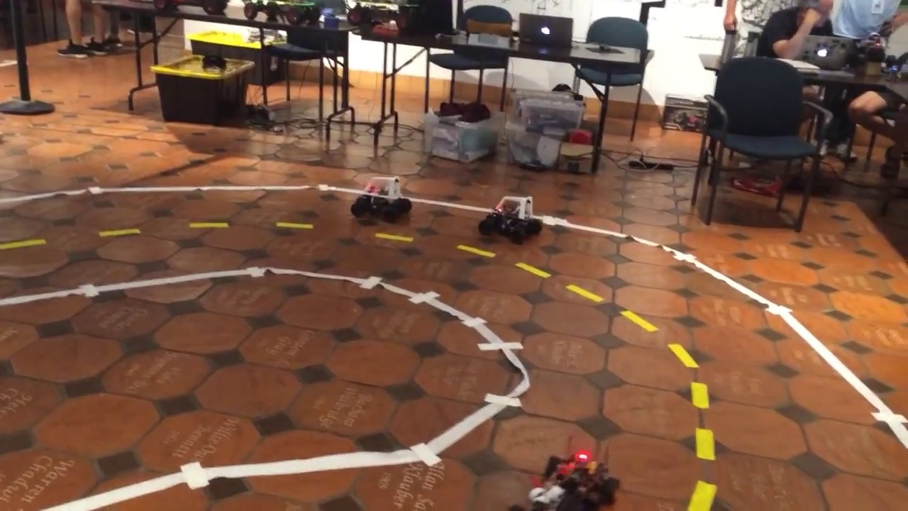
Here an NN driven bot exhibits passing behavior. This was deliberately trained with about 40 examples of passing.
sly sand
interesting, seems to be an hobby rc truck conversion kit to make it smart
pine bramble
You can use almost any RC car or truck chassis. The Donkey Car part is what you build on top.
sly sand
otherwise do you know of something similar for a tracked robot with arms or a crane that isn't a toy but something more serious ?
pine bramble
No, not unless you're willing to spend around US$10,000.
The cheapest ones that aren't toys are at least US$5000.
sly sand
I originally wanted to go lego mindstorms education version but it's completely proprietary and my sklills with arduino are useless on it
sly sand
pine bramble
No, not unless you're willing to spend around US$10,000.
well no but might be good to know regardless
never know when I may have a windfall, I'd strongly consider the 12k$ DIJ programmable/moddable drone platform and a drone type.2 license if I did
pine bramble
I'd recommend investigating the Donkey Car project as the chassis you choose can be almost any. If you are looking for a heavier and slightly more robust (but more expensive) chassis, I'd suggest the tracked Outlaw chassis. You could put a Donkey Car controller on top of that or design your own.
https://www.servocity.com/outlaw-chassis-kit/

ServoCity
RobotShop re-sell some of the $5000+ style robot chassis. Waaaay out of my price range, since by the time you add appropriate motors, controllers, batteries, etc. you're up to $10K.
sly sand
I just got access to a MIT style fablab but I don't know these things yet so I 'm not comfortable with having to 3d print my own parts or cut them etc, i,d rather have a kit I just have to assemble and can upgrade with better motors/sensors etc
ooff I see what you mean 😄
"You have a cute 500$ hobby RC car, if you have the money we have a 12000$ version"
pine bramble
Ah, but there's the middle ground too. Say, use some kind of ServoCity chassis (which are highly modifiable and very sturdy), and appropriate controllers, etc. I'd back-of-napkin estimate you could have a functional autonomous robot for around US$2000.
sly sand
chassis seems like a good thing to invest one if it's easily reusable and easy to mod
If I had the money this would be what i'd get because it seems to fit my needs: https://www.robotshop.com/en/leo-rover-4wd-developer-kit-unassembled.html
pine bramble
I'm currently in the process of building a goBILDA-based Mars rover, and because the shipping to New Zealand is outrageous the total cost of the robot will be well over NZ$3500. So I'm doing it in stages, starting with a four-motor version with no rocker-bogies. So you could get a starter chassis from ServoCity and begin building in stages too.
sly sand
it's not naked(has a bodyshell) and seems to be a good compromise between on-road and off-road for a mobile platform
pine bramble
sly sand
it's not naked(has a bodyshell) and seems to be a good compromise between on-roa...
There are a number of robots like that on the market, and that's a good quality robot. The only thing to consider with that style of robot kit is that they're not always very extensible/modifiable. And for that much money you can actually build a more capable ServoCity robot as a base platform, but you'd have to design much of it yourself (where the Leo is a kit but makes a lot of the decisions for you).
sly sand
I'm in an ace age country too don't want to be unable to use my outdoors robot for 10 months a year
pine bramble
sly sand
I'm in an ace age country too don't want to be unable to use my outdoors robot f...
In those situations people often choose an alternative, which is to build a robot that can operate in office buildings or parking garages.
pine bramble
Well, it sounds as if you are perhaps on your journey now 😄 I've got to go. Nice chatting with you.
sly sand
yeah thanks for the advices
pine bramble
You're very welcome.
sly sand
the problem with any project i want to make is there seems to be too many choices
so I like to be constrained on certain decissions
Like I want to make a rc car mobile smart platform. Ok need a chassis and motors and servos and ESC
there are thousands of each
I could make my own shell and own EC but again thousands of CNC machines and 3d printers plus I have to spend years learning it
so in the end I always give up because of too much choice and it seems I need to learn as much skills as an astronaut or nuclear engineer
mortal dagger
How large motors are you looking to run?
sly sand
can't find my old posts but I'd like a 4wd off-road outside platform that can carry about a 200 pounds load and be around 1 feet large/1 feet long. VColtages involved from my old research would be 16-20V motor for each wheel
mortal dagger
Probably need some pretty hefty motor drivers for that.
sly sand
found a piece of my old posts, I had found a pl;atform that seemed to be decent and it was driven by 4 650mA@12V motors
this one was with mechanic wheels and steel robot chassis but with a 40kg load so 70ish pounds
so not quite what I'm looking for and was a naked platform too (no weatherproof bodyshell)
it was 400-500ish$ I think
pine bramble
sly sand
so in the end I always give up because of too much choice and it seems I need to...
Well, I could post the old cliche of "a journey begins with a first step" or something, but being disabled by choice is a privilege not everyone has. One of the members of our Personal Robotics server is a 9th grader living in New Delhi who builds robots out of junk, and frankly puts a few of us with much greater resources to shame, in terms of actually getting stuff done rather than talking about it all the time. So starting with even a smaller kit and beginning to build on that is truly a start, and once you get into odometry and sensor handling is probably more "real" robot than most people actually ever build. Most people end up with remote-controlled, robot-shaped toys.
The actual hardware to build an autonomous, self-navigating robot is really not that big an investment, but can take a great deal of effort to get running, and could provide many years of learning. Buying board after board, sensor after sensor, just makes us consumers. Digging into a single robot project and maxing out what can be done with just that base platform is something I see few people (myself included) actually accomplish. The advice I've had from one of the more senior, experienced members of the DPRG is to do just that: stop monkeying around buying stuff and just build a single robot and get it running. And then, as he says: "Run the robot. A lot."
http://robots.org.nz:9627/wiki/Wiki.jsp?page=BuildSequence
Page version 3, last modified by Admin, on
sly sand
that's why I want one that can carry a load, I recently was diagnosed with osteoarthritis and this could help my quality of life in the long run
But yeah I understand the "not starting with blacksmithing gold (which is very expensive and technical) when you don't have the skills the handle it when you could start with inexpensive tin and make mistake" that I should heed 😄
This is more of a "can't change it" problem though
because if I could mod them a mainstream hobby r/c car would be perfect same for lego mindstorms
but hobby r/c car are proprietary, if I can't send commands to the ESC I can't make it stop and override the RC control if it's going into a wall
pine bramble
I'd say probably the cheapest way to get started at that scale of robot (i.e., one strong enough to carry things) would be some kind of ServoCity or goBILDA chassis kit with a RoboClaw motor controller and Yellow Jacket motors. That in itself is pretty expensive as a start, but you could build on such a platform for many years. The Yellow Jacket motors are expensive but very powerful, and the whole Lego-like nature of those products means you could continue to add features as you like. You could start with a two motor robot and then as you go add a second pair of motors. Like I said, I'm working on a four motor start on a Mars rover and will add another two motors and the rocker bogies later.
If you start with more of a fixed kit that has a bespoke chassis (rather than Lego-like) it makes it much harder to modify in the future.
sly sand
and they often add things even to the motors like sensors and a controller chip so that it's PWM/SBUS but proprietary and can't use it without their ESC
pine bramble
We often get people coming into our forums with ideas of building walking robots as big as humans, and it's hard to tell them that very large teams of people (such as at Boston Dynamics) have spent years and millions of dollars on hardware and software R&D to build such things. They think they can do it on the cheap.
And they also arrive with no existing hardware or software skills and just think they can just jump in and suddenly have Robby the Robot. And when I suggest they might start with a small two or four wheeled navigational robot kit to learn the basics required to even begin such a larger project they then just give up. Or when they realise it is actually going to take some serious effort at learning hardware and software skills they weren't up for that either. So they weren't really serious after all, which is the nature of people I guess, i.e., getting enthusiastic about something but the enthusiasm quickly wanes. Like the idea that it might take many years to play piano or violin or tabla.
So like I said, if anyone is actually interested in building a robot, start going down that path by considering one's goals and then jump in with some appropriate level of kit to get going. Over the past few years I've kinda assembled notes about this, including things from some of my friends, and collected it here:
http://robots.org.nz:9627/wiki/Wiki.jsp?page=GettingStarted
Hopefully that gives people at least the ability to begin thinking about what they might want to do rather than just "build a six foot tall walking robot", which will never happen unless one is independently wealthy and can hire a large team of hardware and software engineers. It's nice to dream, but it's also nice to have a working robot that's more than a toy (which gets boring pretty quickly).
Page version 1, last modified by Admin, on
sly sand
I see, not like electricity vs electronics then where more weight and more voltage usuallly mean simpler than a microelectronics version on an arduino/chip
pine bramble
A fairly limited but pretty cool start is the little tracked Zumo robots from Pololu. I've seen people do pretty amazing things with them, and they just run on an Arduino, a pair of small N20 motors and four AA batteries. So that's the smaller end of the size scale but with a single Zumo you could spend years having fun with it. I've even seen AI style cameras mounted on them running around in a house following people. The KISS principle is certainly true with robots.
sly sand
seems like a great start and buyable in canada without astronomical customs fees
ant not a dead-end like all those cheap "smart" cars kits with cheapest parts and yellow wheels
last question, do these sort of things, robots, robots parts etc ever go on special? surely even parts for industrial/scientific applications ruins sales sometimes ?
ie: should I wait for black friday/christmas ?
pine bramble
The one downside of the Zumo is that it's pretty difficult to add wheel encoders. I managed to do it (and blogged about it here: https://robots.org.nz/2021/05/26/in-pursuit-of-the-club-robot/) but at the point where you want to begin exploring odometry you'll hit a wall. But you can also kick that can down the road for a long time, as there's lots to do with a Zumo. Pololu does follow the US cycle of sales, and have had Zumos and their parts on sale. So yes, I imagine you'd see things on sale. I can say that Pololu are really nice, helpful people and if you mailed them they'd probably even tell you when the next sale date is going to be. I've had excellent tech support from them. There are a handful of companies like Adafruit, Pimoroni, Pololu, SparkFun, etc. who are very helpful and running solid business models and supporting healthy communities.
sly sand
odometry seems to have a lot of solution like an opentx transmitter/receiver though
seems to be more of a problem of fitting/attaching/screwing the receivver to something that wasn't made for it than anything else
but opentx gear usually is made to be pretty universal, same with FPV style cameras etc
hum opentx is telemetry nvm
pine bramble
I'd say odometry is a very fundamental feature (with requisite hardware and software skills) necessary for proper robot navigation. Without odometry your robot can't even run in a straight line. One of the DPRG challenges is to drive a robot from a fixed mark forward about twelve feet, turn around and come back to the origin point. Their robots are nailing that within fractions of an inch (like 1/8"), simply impossible without odometry. As a "first challenge" it's exceedingly difficult. I've not managed it yet.
sly sand
Basically I've followed a couple optional electrical engineering courses and a robotics semi-graduate course and I've been looking to use that theory every since
The end-result of the course was being able to find the noise equationss of sensors with matlab so you could make a simple kalman filter to do sensor fusion
but we didn't build anything or take measure from the sensors, was just the theorical side of things
pine bramble
Sure, and one picks their battles. I'm not a math whiz so I ended up using a BNO055 IMU, which does the sensor fusion for me.
sly sand
yeah what i'll do as well. Liked the specs of that Bosch chip
I never liked how my university was too theorical
I don't see the point of a robotics course if you don't know how to build a robot to actually measure anything with the course 12 years later
They were more interested in training future PHDs than peoples who wanted a job with real-world constraints apparently
almost half of it was on autonomous driving as well and the pros and cons of various types of navigation
and various sensors that could be use for navigation
vocal bear
this has been a fun conversation to lurk thru
pine bramble
Yeah, sure. I built a robot in high school back in 1979 and got back into a few years ago, inspired by a YouTube video by David Anderson of the DPRG. I'm happy to say we're now friends and he remains an inspiration. To give you an idea of his prowess, he has a six wheeled outdoor robot called the jBot, with wheel odometry and an IMU, and with that demonstrated the ability for his robot to do that origin-to-waypoint-and-return challenge, but do it outdoors over 1000 feet, with logs and trees and rocks in the way. At the beginning of his "second hat trick" video (in the Navigating Through the Woods section) he drops his hat on the ground as the robot drives off, it goes up to a virtual waypoint, turns around and comes back, driving over the hat. It's hard to explain to people the genius of that work. Just with odometry and an IMU, no GPS. David is by far the most advanced at robot navigation I know of. Bar none.
http://www.geology.smu.edu/dpa-www/robo/jbot/index.html
So if anyone needs a challenge, just try to emulate that trick... it's actually one of my own goals.
sly sand
my teacher was part of a robotics labs that mostly advanced research on industrial robots, crowd of cars self-driving vehicles and aerospace fields
one of the student had built a fast walker cat that mostly used mechanical legs and that neeeded almost no power because it could keep going just because of the properties of springs
I mean I can't even get started on a robot car and meanwhile they sold several patents on making an automated garage that can recharge electrical cars and make basic repairs to a large carmaker...
I guess if I can get past edge-following navigation that would be nice
And actually do voronoi navigation so it doesn't just follow edges...
I'll setup a pricewatch on the Zumo 32U4 Robot Kit
seems to be what I need to finally start on robotics and seems to be expendable and not the cheapest of the cheapest quality
My 1st customization goal would just be to have it run away from me in fear 😄
and kinda playing with it by trying to fool its sensors so it doesn't detect me
ie: like dressing in black to avvoid IR sensors or blinding visual ones with a bright light
sly sand
pine bramble
We often get people coming into our forums with ideas of building walking robots...
I think that come from reading history about superhumans in the renaissance or later who were one-man army for science and/or engineering
without realizing that things have become much more specialized, smaller and with much more tools today
and much more complex
and much more laws too and safety things
and even magdeburg guy with his vacuum sphere public experiment didn't raise the horses from birth or smelt the sphere, he had a team
pine bramble
sly sand
I guess if I can get past edge-following navigation that would be nice
Yeah, but on the other hand, I can buy an advanced Time of Flight sensor the size of a grain of rice that has centimeter accuracy at 4m and uses about 20mA, or a BNO055 IMU, which is a truly advanced device, either for about $20. And we can build what was sent to Mars in the 90s now for about $2500. So the sky's the limit nowadays.
sly sand
yeah but if you are completely uselesss at building stuff like me you depend a lot of otherss
I'm working on that especially with fablab courses and membership but atm I can barely solder and can't cnc/3d print anything
and even then back then you had a reliability and scaling up that you don't have on 20$ chips from today
pine bramble
I avoid 3D printing as it's actually a religious cult from Mars.
sly sand
it always impressed me how old servers like cray or SGI outperform today computers when reliability is a thing or parallel I/Os
sly sand
pine bramble
I avoid 3D printing as it's actually a religious cult from Mars.
Seems like it would save a lot of time and money on chassis/shekll for me though
since without a chassis I can't even start
primal shell
I don't avoid 3D printing, as it's a fun way to prototype stuff. I could just CNC stuff, I suppose.
 pine bramble
See?! Every time I mention it's a cult a bunch of people tell me how wonderful 3D printing is! 😱 Next thing is I'll be a ceremony with thousands of other people getting married to a stranger... 😝

 sly sand
well porsche can honor warranties on their 1950s cars because of 3d printing from powder metals
I kinda think it's a cult too atm, but as industrial-grade ones get cheaper I think it will get more interesting
Hopefully in my lifetime we can prove the RIAA wrong and download a couch
sly sand
@pine bramble bought the newbie robot we talked about, seems to be at a low price point in its price history atm so don't think it will be cheaper around black friday/etc
vagrant thunder
I mean, 3d printing is a fun hobby, but the time it takes to go from nothing to printing takes either a considerable amount of time and effort, or a considerable amount of money. I picked it up out of curiosity, but it really is one of those things where the only way to learn it is to do it. For most, it might be easier to start with plywood or t-slot extrusion.
I'm scared to count on black friday for most electronics this year.
sly sand
I have a fablab 3 streets away from me so I can use their 3d printed stuff at cost
and they have a mid-top end one
or their CNC machine or various saws etc
vagrant thunder
Yes, but learning fusion360 is a process as well haha
Also, there's a difference between "they let you use their printers" and "they print it for you."
sly sand
They say their 3d printing stuff is: Printrbot Pro / Tevo Tarantula / Sense3D
And they give a course so you can do it yourself
I initially went because my apartment is too small to solder, my 2 smoke alarms would go crazy and I'd probably drown from my sprinklers 😦
native cipher
sly sand
<@!828135237744984114> bought the newbie robot we talked about, seems to be at a...
which one is it?
sly sand
@native cipher Zumo 32U4 Robot Kit (Assembled with 75:1 HP Motors)
native cipher
nice! I love Zumo.
it has gotten pricier, though
sly sand
was 200$ cad, about 155 US$. But worth it for me because the alternative was very cheap 80$ smart cars you can'tr upgrade/customize with flimsy boards and flimsy yellow wheels and the cheapest of the cheapest sensors
and most of them don't even have documentation
thanks to me it passed to unavailable - we don,t know when it will be back in stock on amazon 😄 🤣
pine bramble
sly sand
<@!828135237744984114> bought the newbie robot we talked about, seems to be at a...
Ah well, congratulations on your new robot! You might even make yourself a robot sumo arena and find someone in your area to compete against. One of the DPRG members put black tape on his nice wood floors (the horror!) and had his drive all over his house using the line follower. Others have put analog IR sensors or ultrasonics on theirs and gone off-track. Sky's the limit! 😃
sly sand
I hope so, the controller chip seems a bit limited compared to a mega 2560
native cipher
it is, which is why I am building my own alternative zumo-based robot using RP2040. But 32u4 is powerful enough for quite a few things, so it should keep you busy for a while.
 main echo
anyone familiar with controlling a mini-cheetah-style motor with CANbus and Arduino? I am hacking that and I have a few questions about things like max CAN messages per second.
sly sand
native cipher
it is, which is why I am building my own alternative zumo-based robot using RP20...
yeah and as Ichiro said yesterday, in my own words, gotta start with tin before you can do goldsmithing
sly sand
so, just theorically, I saw some 80 kilowatt servos on digikey, what kind of stuff would that rotate related to robotics?
native cipher
I can't even imagine... can you share the link, just for fun?
sly sand
15kw a bit off, but I swear I saw a bigger one a few months ago from omron (https://www3.panasonic.biz/ac/e_download/motor/fa-motor/ac-servo/catalog/minas-a5-2_ctlg_e_201504.pdf)
say rated output 15kw
sly sand
While perusing brochures I've seen some lines of servo motors going from arduino scale (mA/5V) up to kw before and that always kinda surprised me
vocal bear
I also don't know of a robotics application, but maybe a big servo like that could be used for very precise motion of a huge armature/load
sly sand
Trying to read robotics related phd thesis and I'm already lost in the first line of the introduction 😦
I'm lost at "cable-driven parallel mechanisms"
lone skiff
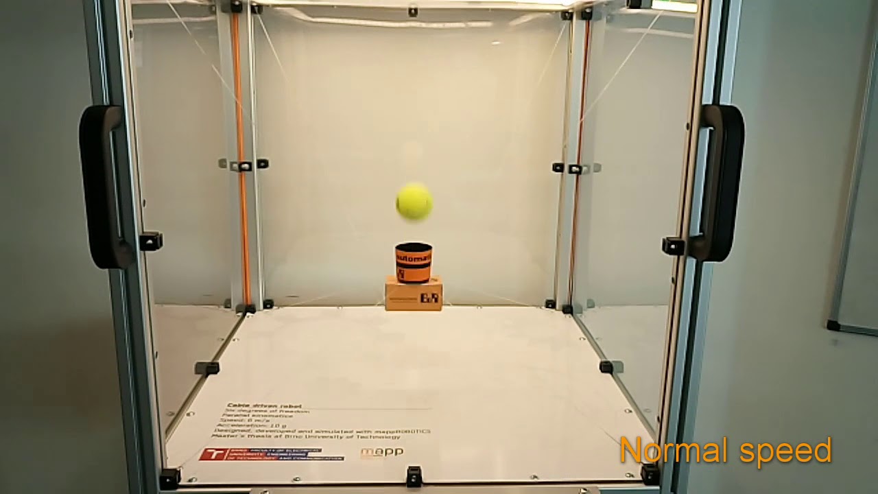
CableEndy is cable-driven parallel robot project at B&R Automation Brno (CZ) office. Juggling version of robot was created for international engineering fair 2017 in Brno (MSV 2017) as eye-catcher.
Contact for B&R customers: andrej.rajnoha@br-automation.com
Contact for public: andrej.rajnoha@gmail.com
native cipher
@lone skiffthanks! Haven't seen such designs before
sly sand
vocal bear
I also don't know of a robotics application, but maybe a big servo like that cou...
I guess my guess is as good as anyone. Mine is rotating a baseball bat to hit a baseball ball at around 0.2c
to make a planetary homerun
vocal bear
That's an interplanetary home run lol
lone skiff
Obligatory: https://what-if.xkcd.com/1/
sly sand
I know about it that's why I picked 0.2c 😄
 versed jungle
hello guys could anyone plz suggest the resource to find the best topic title to fix
sly sand
new kitten has arrived, but it's cold atm due to canadian ice age. Screwdriver on the side for comparaison

 jolly eagle
is it common to be able to flip axis on something like LSM6DS33 or MMAB451 for space reasons? im flying a rocket and wanted to mount the board so Z was away from the ground(but cant because its too wide to fit in the tube that way) then X and Y would be whatever, but say I turn the board on its side and have X be away from the ground, will it mess up anything like the gryos, mag etc or as long as I know which orientation goes to which axis then it will work the same?
sly sand
They probably use matrixes for calculation and you just apply a rotation matrix before feeding your matrixes to it or getting matrixes from it
but yeah imho it seems obvious that you have to calibrate sensors at least to tell it where 0,0,0 is and your rotations
LSM6DS33 seems to have a register for user-orientation of axes