#help-with-robotics
1 messages · Page 8 of 1
 tender mulch
i'd do some research on PID
 cloud sorrel
Well, it's not even an issue of PID yet
No point of plugging it into PID if it can't generate usable torque. (which I have tried, but it failed as expected due to lack of output to affect input)
tender mulch
is that stepper rated at "several hundred RPM"?
tender mulch
steppers are high torque, low rpm devices, generally used for precise positioning
cloud sorrel
Right, in my current setup RPM is more or less irrelevant.
It should just be a measure of the saturation point
I only care about the torque / jerk available to use as PID control output
tender mulch
so if its spinning at 1 rpm you can stop it easily?
tender mulch
then maybe a power supply issue
or wiring, at that speed it should provide high torque
cloud sorrel
What's an easy way to try giving it more power safely?
tender mulch
have you run standard example sketches?
cloud sorrel
Yes, behavior remains consistent
 lone skiff
What's the inertia of your flywheel?
cloud sorrel
@lone skiff how do I calculate that?
lone skiff
0.5 * m * r^2 if it's a disc.
cloud sorrel
Starting from a standstill, going at 1-20 rpm, it's trivial to stop it. torque can't be more than like an oz or two
tender mulch
@lone skiff @cloud sorrel i think until the torque issue is solved you are at a standstill
cloud sorrel
Yeah
tender mulch
is it a 12v wall adaptor?
cloud sorrel
Essentially this: https://www.amazon.com/dp/B077PW5JC3/
Checked the voltage and amperage, and it is just a little over 12v, 2a
tender mulch
12v under load?
cloud sorrel
At rest
tender mulch
i mean when the stepper is turning
cloud sorrel
Not sure
tender mulch
it may not deliver enough power
cloud sorrel
What's an easy way to try giving it more power safely?
tender mulch
you'd need to try a different power source
cloud sorrel
Right, but I can't drop $100-200 on a lipo that has a good chance of not working. I would guess a bench power supply is what I'm looking for, but never bought one before so not sure what it would cost, or what a good one looks like
tender mulch
try measuring volts / amps while its running
cloud sorrel
Where would I measure? What would the drop tell me / how much should I be expecting?
tender mulch
measure volts across the input to the H bridge for a start
cloud sorrel
It would probably take 30-60 minutes to get everything connected and hooked up again. It'll have to wait for another day unfortunately
tender mulch
np, we're here 🙂
it should be pretty close to 12v on the input while motor is running, if not the adaptor isn't supplying enough current
cloud sorrel
Gotcha, so if there's a large voltage drop then it's the power supply not having enough juice
tender mulch
exactly
cloud sorrel
Thanks! I'll follow up once I've been able to try it. 😄
lone skiff
I would advise trying to actually calculate the flywheel inertia versus the specced motor torque, too. You can predict what kind of angular acceleration you would expect if everything was working correctly.
 real kestrel

The Cubli is a 15 × 15 × 15 cm cube that can jump up and balance on its corner. Reaction wheels mounted on three faces of the cube rotate at high angular velocities and then brake suddenly, causing the Cubli to jump up. Once the Cubli has almost reached the corner stand up pos...
waluigi, how smart!
 river timber
Well, that's one way to get all of your robotics work all squared away
 vagrant solar
Hello

Avishkaar manufactures of DIY robotics kits for kids. Avishkaar promotes STEAM learning and encourages people to become Makers through its initiative of MakerSpaces.
 rustic shell
is the cubli loud? and i want one
 primal shell
You can hear it in the video, it doesn't seem too loud. There's probably enough information out there to make one, but it looks like you'd need machining skills and access to a machine shop. I suspect it's possible to simplify the design for easier building (and/or offer kits) but I'm not aware of an effort to do either.
 bold knot

Builders can create and code one of five personality-packed robots or dream-up and build their own creations
 river cipher
and this is the error that pops up:
 next ravine
Im using a servo like this: https://www.amazon.com/LewanSoul-LD-20MG-Standard-Digital-Aluminium/dp/B073F92G2S/ref=sr_1_1_sspa?dchild=1&keywords=20kg+servo&qid=1592417456&sr=8-1-spons&psc=1&spLa=ZW5jcnlwdGVkUXVhbGlmaWVyPUEyWk5QOEdERTVNUFpUJmVuY3J5cHRlZElkPUEwNDUxMDQ5UUpVUFFUWlVSUFVYJmVuY3J5cHRlZEFkSWQ9QTAxOTM4NjgzMElCV1hHQlJGRDg2JndpZGdldE5hbWU9c3BfYXRmJmFjdGlvbj1jbGlja1JlZGlyZWN0JmRvTm90TG9nQ2xpY2s9dHJ1ZQ== in a project and im powering it via USB (5v of USB to the 5v pin on the servo, GND of the USB to GND of my microprocessor)
This works but:
- Is this OK do to?
- My servo gets really hot as it seems its constantly engaged (I can't move the servo by hand when its plugged into USB). Sending commands to it works as expected but again, it gets very hot.
Any idea?
primal shell
You want to connect ground of the servo to the USB ground (and thereby the microprocessor ground)
next ravine
@primal shell thanks, I think thats what im actually doing, ground of the servo goes to ground of the usb which then goes to ground of the arduino
but any idea why the servo gets HOT sitting there?
primal shell
Could be a few things, like it can't find a stable position or it can't get where it wants (mechanical obstruction, pulse width problem, or gear damage) so it's always trying to move.
next ravine
Maybe it is PWD problem
primal shell
Different servos need slightly different timing, and the useful range is a small fraction of the PWM generator's capability
next ravine
@primal shell im using CircuitPython so in my case this is how I init the Servo
so the duty cycle is what sends signal to the servo to move right?
primal shell
Right. Normally the refresh rate is 50-60Hz or so, and the pulse width is 1 to 2 ms. I think that's a duty cycle of around 5-10% (but it varies with the repetition frequency)
I think CircuitPython lets you express it as an angle, and does the conversion for you
next ravine
so I should play around with the duty cycle to get it to be in a good position so that it doesnt heat up
 tranquil coyote
help me someone
 hollow coral
hi all, I recently salvaged a battery of 5 18650's from a little russle hobs mini vacum cleaner and was going to use them in a project but noticed they didnt have any form of bms or overcharge protection. I was wondering if these things are actualy that vital if i want to use this battery will i need to buy and wire in a 5s bms chip or am i fine assuming that if they didnt deem one necissary I dont need one either?
hollow coral
im guessing it has something to do with the expected current output
 sharp solar
@tranquil coyote What do you need help with?
tranquil coyote
i tried to make a self balancing obj avoiding robot
but there is some problem in it
ill send everything in an hour
 slate sparrow
where is it
 sterile silo
Motor controller confusion?!?
I'm measuring set stable levels of both A.C. & D.C. voltage that the motor controller is putting out to the motor & don't understand how or why it'd be supplying both A.C. & D.C. voltage to this motor.
There r 4 different power levels & at each level both the A.C. & D.C. voltage level hold stable & consistent
10.1 D.C.
10.6 A.C.
18.6 D.C.
13.8 A.C.
27.1 D.C.
16.2 A.C.
35.6 D.C.
17.9 A.C.
 toxic fog
What kind of motor is it?
sterile silo
O wait, I'm measuring it wrong
Well, thinking it wrong I guess
I was measuring where the wires come off the board, not taking into account this big guy:
@toxic fog
Just a layman theory - is so much A.C. a side effect cause of the motor controll board being designed cheaply? Thus requiring the inclusion of that BIG coil in the circuit?
tender mulch
@sterile silo Do you have any information on the controller?
sterile silo
Hi @tender mulch unfortunately no, it's just a circuit board that is in the treadmill. O' & btw that's what these parts r coming out of, an old treadmill.
tender mulch
well, it'll be very hard to say what's what without more detail. the motor says DC but I assume the device plugs into 120VAC?
sterile silo
Yup correct. Here's a pick of the control board.
Red & black wires u see up front are going to the motor.
tender mulch
do any LEDs light up? Current limit, etc?
first off - does it work and you are curious or are you trying to fix it?
sterile silo
Here's a pic of the other board
tender mulch
second is control, first was power
sterile silo
Yup, all the led's light up & it seams to be fully functional. Na, I'm looking into other project ideas to use the parts in. I'm just trying to better understand what all is going on with it.
tender mulch
yeah, hard to say why you are getting the readings you see, if it works my guess is "that's normal" 🙂
sterile silo
One idea that I'm liking is a band saw or generator. :-D
Ya good point.
But that's y I was wondering if the crazy readings was due to a poorly & or cheaply designed control board.
tender mulch
many times a multimeter will read AC "spikes" and indicate as "steady AC". Brushed DC motors can be electrically noisy. can't comment on board design without more data.
sterile silo
Ah ok. Makes sense
tender mulch
maybe you can Google up more data based on part number, but prolly not as it looks like it was OEM'ed.
sterile silo
Ya, I didn't have any luck with Google with the boards.
tender mulch
or a service manual for the whole treadmill
sterile silo
Hmm didn't try searching for the service manual. Nice idea :-)
tender mulch
it may only show "electronics box" but worth a shot
even a basic wiring diagram would be a clue
maybe it drives the motor with PWM which would show up as AC on your multimeter
sterile silo
O' @tender mulch , would u know what the 2 blue wires r for that are wired to the motor? The pic is above.
tender mulch
could be feedback for speed control
sterile silo
I went & rebooked at the pic I posted earlier & it looked like there were 3 wires instead of 2 (not counting the red & black) so I looked again & retook the pic.
The blues go to the switch, & the other go to that other board, connects where my thumb is pointing.
sterile silo
But with where they connect, do u think that they indeed cld be feed back for a speed sensor or something like that?
Ah, gotcha.
tender mulch
once you get bigger than toy car motors "standard" doesn't apply
sterile silo
Lol
Speaking of 'toy car' that's another use idea I have, putting it in a 1/5th scale RC car. :-)
Lol, I love getting new parts to work with. Lol, SO many possiblies!
tender mulch
it's a big motor, you might be able to get some clues by spinning it and see where voltage comes out
sterile silo
O for using as a generator?
sterile silo
I'm impressed that even at only 10V it still got the belt moving with my 230lbs butt standing on the belt
Very simple
tender mulch
it might be PWM, the DC reading would be lower than peak actual volts
sterile silo
Na, the 10.1V reading is with no load. I didn't have a meter on it yet when I did that.
tender mulch
how many rpm? DC motors are happier at high RPM
sterile silo
tender mulch
i assume it wasn't spinning that fast...
sterile silo
That's the motor ratings, but as far as the tread mill used it, it only applied between 10.1V & 36.6 to run the tread mill at 1-4mph
O goodness no.
tender mulch
picturing six million dollar man cruising on his treadmill
sterile silo
The rating is 130VDC & THE most it applied to the motor was like 36VDC
Lmao!!!!
Lol, used to love that show!
tender mulch
maybe you can chat up someone at Icon Health for a manual
sterile silo
Hmm, I wonder how to graph that to see how fast that treadmill would be going if the full 130VDC was being applied.
tender mulch
put it inside cinderblocks before you test that
tender mulch
ok, gtg, lemme know if you get more info on it
sterile silo
I'd need the mithbusters bomb shelter.
tender mulch
lol
 flat raft
xD
sterile silo
K will do. Have a great night!
flat raft
if only everyone had the Mythbusters equipment
sterile silo
Lol ya really!
flat raft
if we all had the Mythbusters equipment, Mythbusters wouldn't need to exist because people wouldn't be stupid
and they wouldn't believe that we didn't land on the Moon
sterile silo
@tender mulch
Got more curious & actually did the math. Sadly it's much less impressive then I'd originally imagined. It only works out to be about 14.5mph with an applied 130VDC.
 stable helm
is there a good way to gauge torque? for example these motors
it says the holding torque is 28 N.cm Min, but i cannot picture that 😦
like how can i look at that value and say "hmm 28, that's good enough to push or pull ...."
lone skiff
If you prefer imperial units, 135.6 N-cm is one foot-pound.
The motor weight is 220g, so another way to think about it is if you attach the motor to a 5-inch arm, it could just barely hold itself horizontal with its own torque.
stable helm
hmm i think i need one of these motors to actually test
i have a 1kg weight that i'm pushing with a design something like this
lone skiff
You'll get a significant mechanical advantage from the screw thread... it's like gearing down the motor.
 stuck coyote
primal shell
stuck coyote
primal shell
There are different kinds of motors: what kind of motor are you driving?
 nimble burrow
Hey, has anyone got experience with murata PIR sensors and how i would get a useable signal from it?
primal shell
Many of the PIR sensors provide a simple logic level output.
nimble burrow
@primal shell yeah in hindsight I shouldve got the ones with an evaluation board
I have made a circuit with an op amp and it sort of works but for some reason it needs constant retuning
primal shell
Ah, you have just the pyroelectric crystal itself?
nimble burrow
Yeah just the 3 leaded component
primal shell
Or perhaps the version with a built-in FET amplifier
nimble burrow
Just this, I dont think it has any processing
I'm feeding it 3.3v from a MKR and I'm getting a mv output from the source
primal shell
A lot of the 3-lead ones have a built-in FET like this
nimble burrow
But it seems very unstable
primal shell
Do you have it behind a lense?
nimble burrow
Ohh it seems to have one
And yeah but I took the lens off for testing as it's making the fov too wide
primal shell
This page (from which I lifted the above figure) has a decent explanation https://www.embedded.com/using-pyroelectric-infra-red-pir-sensors-for-motion-detection/
It is a low level signal, and you generally need circuitry to figure out which changes are significant (quicker differential changes in particular). A whole lot of them use the same BISS0001 chip http://www.ladyada.net/media/sensors/BISS0001.pdf and its data sheet also has a lot of useful information on how the circuitry works
nimble burrow
Cheers mate I'll have a read through, I've been really stuck on this for almost a week😅
primal shell
Oops, the datasheet doesn't have much, but this writeup does https://www.mouser.com/datasheet/2/737/pir-passive-infrared-proximity-motion-sensor-932858.pdf
nimble burrow
Thank you:) I might have to give in and get the biss IC
primal shell
Sort of like the smoke detector chips, there's a bunch of engineering already done for you in the chip, which can be handy if you're more in the "I just want to use this" camp than "I want to understand the basic physics here" one.
Sometimes when I really do want to get into the basic physics, I'll start with the off-the-shelf solution to learn more about how the thing operates, then get into the details.
nimble burrow
Yeah I definitely jumped in at the deep end having only done this for 2 weeks but I'm really enjoying it, I just need to find a good balance between learning and making progress
I'll keep that in mind as I'm being a bit stubborn lol. Thank you for helping me out mate, I'll see if I can get it working now
primal shell
I totally understand (I can be quite stubborn too). It took me a while to get used to the idea that it's okay to start with the off-the-shelf solution and then work from there, but it's saved me a lot of time and aggravation. Being able to measure what's going on in a working circuit is a huge help when I
try to build my own version
 stone sapphire
hi im trying to turn my mouse cords into servo postions and i need to kinda do that map function in arduino but in pyhton. so i need to turn like 0-1200 to 0-180
stone sapphire
ah ok thank u
 brazen tangle
What do you guys think about this? https://www.banggood.com/KJS-1509-3-24V-2_5A-Power-Adapter-Adjustable-Voltage-Adapter-LED-Display-Switching-Power-Supply-p-1415389.html?ID=47184&cur_warehouse=CN
I don't have a power supply and I want something for robotics/embedded projects
The alternative is this, but then I won't have voltage range
https://www.aliexpress.com/item/32270275630.html?spm=a2g0o.productlist.0.0.1c787aefJ4Rfaz&algo_pvid=c1b5547b-350c-4890-b21b-544316ced464&algo_expid=c1b5547b-350c-4890-b21b-544316ced464-0&btsid=0b0a3f8115941989216777647ee37d&ws_ab_test=searchweb0_0,searchweb201602_,searchweb201603_

www.banggood.com
Online Shopping at Banggood.com!

aliexpress.com
Smarter Shopping, Better Living! Aliexpress.com
primal shell
You could buy a fixed voltage supply and add a variable voltage adapter like an RD6006, but that would probably be more expensive.
 twin chasm
+1 for RD6006, I just put one together and so far loving it
brazen tangle
So what is a good DC power supply solution if I would be working with motors
which does not cost much
primal shell
@brazen tangle Ordinary flashlight batteries can be a good start.
 native cipher
@brazen tangle depends on what kind of motors. 5V TT motors is one thing, Falcon 500 motor used in FRC is quite another (12V, 250A stall current).
What voltage are your motors?
brazen tangle
@native cipher Right now, I'm thinking about small servos (maybe 3 of them) and 4 small quadrotor motors
native cipher
then I would use 3 cell LiPo together with a 5V buck converter, whihc you can buy easily on Banggood
brazen tangle
Also why that KJS-1509 I mentioned is so cheap w.r.t bech supplies? What's the catch?
@native cipher So battery + charger would be cheaper than bench power supplies?
native cipher
problem is that cheap bench power supplies typically can not handle high current. Typical LiPo battery can easily handle 50 amps; the supply you linked provides only 2.5, which is not much.
check what is the current required by your motors
brazen tangle
@native cipher Even the 5A version of that is suspicously cheap. Is it because bench supplies have current limit?
native cipher
I honestly do not know... I expect they have much better precision - voltage doesn't drop under load
 clear tree
Can I drive a ULN2003/28byj stepper using a feather (using the usb/battery power for the motor current)?
native cipher
the only difference between using a feather and using any other kind of arduino board is that feather uses 3.3V volts as opposed to 5V for Uno - but as far as I know, ULN 2003 works fine 3.3V logic (e.g. see https://www.robotshop.com/en/elecrow-uln2003-stepper-motor-driver-board.html)
clear tree
thanks, it seems to work fine, it just took me a while to figure out the right permutations of the wires
now trying to figure out how to control a servo properly
primal shell
It's generally easiest to use a servo library to generate the servo waveforms
 wet vine
I can't seem to find a photo of wiring a TMC2208 driver with an arduino.. any help? Just want to control it with the uno
primal shell
This page has some useful information https://wiki.fysetc.com/TMC2208/
wet vine
using that atm, but do I really need a separate input supply for the motor? Or can I get away from the 5v pinout from the board?
primal shell
Depends on the motor, most of the motors you'd drive with a chip like that would want more voltage than 5V. Additionally, the motor power supply will get a bunch of electrical noise on it, so sharing it with your controller could cause glitches or even damage.
One thing I'll often do is use a higher voltage supply for the motor, and have a regulator run from that supply to power my logic.
wet vine
alright sweet 🙂
I don't mind noise too much, as I'm making a film projector to play my dads old films, so a little stutter here and there isn't going to make much difference
native cipher
@wet vine whatbmotor do you plan to use?
wet vine
a NEMA 17 motor
 gloomy quail
I'm quite new to robotics so I can't find any articles on polarity reverse circuits for motors. Can anybody DM a link?
*(As in there are plenty of sites on the internet, but I don't know which one is the right one for my application)
tender mulch
@gloomy quail "H Bridges" are commonly used to drive DC motors forward and reverse if that is what you are using.
gloomy quail
Yeah, that's what I was looking for.
tender mulch
Happy hacking!
native cipher
@gloomy quail and most people buy a motor driver chip which has all the mosfets and diodes in one compact package, rather than create your own circuits. There are many driver chips, for different voltage level and current; good starting choice is tb6612fng
 rocky badge
Does anyone here know of a decent quality and also decently cheap RC transmitter/reciever unit set for an RC project? all I need is ~10+ m range and 5+ channels
 wicked stump
433mhz tx/rx modules are cheap
rocky badge
Thanks, I'll look into them
native cipher
@rocky badge if you want a ready system, try this: https://www.gobilda.com/element-6-radio-control-system-mode-2/
 primal shell
You can generally get a 5 channel Turnigy 5X combo for less than US$30
That Gobilda one is a little more, but is a solid, well built unit.
 flint fiber
im a beginner in robotics and i wanna ask something:
what kind of motor i need to make a basic on/off moving robot?
lone skiff
The simplest is a brushed motor, also often called a DC motor, which just spins when you give it power.
flint fiber
Ok thank you!
lone skiff
If you're curious, slightly more complicated are: (a) the servo motor, which can move to a particular angle, then stop, so good for robot arms and so forth, (b) the stepper motor, which works by "ticks" forward or backward, so it can move by exact angles or at a certain speed, and (c) the brushless motor, which is complicated to control but can do arbitrary types of fancy motion.
flint fiber
Ok! But how do you make a DC motor spin slowly? Because I am making a basic on/off lighting box with a small lightbulb spinning slowly to change color.
native cipher
you use a motor driver chip or shield, e.g. https://www.adafruit.com/product/2927
A Feather board without ambition is a Feather board without FeatherWings! This is the DC Motor + Stepper FeatherWing which will let you use 2 x bi-polar stepper motors or 4 x ...
there are also many cheaper motor drivers, e.g. https://www.pololu.com/category/11/brushed-dc-motor-drivers

Single and dual motor driver carriers get your brushed DC motor projects up and running quickly using modern H-bridges with high-performance MOSFETs that deliver hundreds of watts in a compact package. Give these boards a PWM signal and make your motors go!
primal shell
You probably want a motor driver (which can just be a transistor and catch diode), to make it run slowly, you can use pulse width modulation ("PWM"), which most microcontrollers can generate for you. It basically turns the motor driver on and off quickly and the speed is controlled by how much time it's on versus how much time it's off.
flint fiber
Ok thank you!
rocky badge
Thanks so much @native cipher , ill look into it
 little needle
anyone have pointers on how to implement throw 'n go functionality on a quadcopter
primal shell
I'm thinking watching accelerometer readings, when all axes are near zero, it's in free fall and should start flying.
little needle
but how can I have it so that the quadcopter knows what way is right side up without starting it already flat
lone skiff
It would probably need to know which side is up before it is thrown. It doesn't necessarily have to be flat, but it has to feel gravity and make note of the direction. Then when it's thrown, the gyro can keep track of how it's rotating.
little needle
would it try to have it's measured gravity point down and minimize gyro readings?
lone skiff
I don't understand what you mean, sorry. It won't be able to measure gravity when it's being thrown, but it would know "down" when it was being held initially, and then could maintain that direction through the throw via the gyro data.
little needle
wouldn't there constantly approximately 1g in the true downward direction?
lone skiff
Yes, but the drone won't feel that when it's being thrown, since it's in free-fall. It's accelerating, but the sensor won't feel the force because the sensor is accelerating too, instead of being held in place against gravity like it would be when it's sitting on a surface.
 sinful edge
hi can someone help me please
primal shell
Can you give some details on what kind of help you need? Different people can help with different things.
 lunar tide
What are the best places to get components for assembling tracks?
(Pre-made ones count too)
primal shell
Gobilda makes some really nice (but not cheap) stuff
native cipher
are you talking about tank tracks? do you already have the rest of the tans/rover?
primal shell
Whoops, I was guessing linear motion tracks.
native cipher
Pololu sells DAGU rover 5
lunar tide
Linear motion tracks? // am Polish
Pololu sells DAGU rover 5
@native cipher I want to make something custom from scratch
There's no fun in assembling something with a manual 😋
primal shell
Pololu has some good affordable stuff https://www.pololu.com/product/3033
native cipher
take a look at this.
This is a kit, but it is modifiable - you can adapt it any way you like: https://www.robotshop.com/en/agent-390-tracked-robot-kit-motors.html
primal shell
Some of the Lego track pieces are pretty versatile too
native cipher
and Tetrix sells track kits, but I was not very happy about them: https://www.pitsco.com/TETRIX-Tank-Tread-Kit
nor is it cheap...
cheapest place is AliExpress: https://www.aliexpress.com/item/32838563114.html

aliexpress.com
Smarter Shopping, Better Living! Aliexpress.com
 fading minnow
Hi guys, i am trying to build a sky tracker mount for my dslr. I am having trouble finding a coupler for a stepper motor to a 1/4 threaded rod. The stepper motor I have appears to have a shaft dia of 4.5mm at the flat end and 5mm at the bottom where its full round
 spiral coyote
So guys, i have a question
how do you connect cables to a component that spins so that it don't tangle up??
tender mulch

With a slip ring assembly, your electronics can now twist and turn safely. Add wheel encoders, 360 degree sensors, rotating LEDs, rotors and more! We've seen a lot of people DIY slip ring's ...
 velvet ridge
Does the CLUE play nicely with the Micro:bit CRICKIT?
 chrome dock
@velvet ridge They are pin compatible, so it should work.
velvet ridge
@chrome dock Excellent, thank you! Now I have an excuse^H^H^H^H^H^H^H^H^H a good reason to buy another CRICKIT board.
chrome dock
🙂
sharp solar
Hey all. Having a rather odd issue with my stepper motor, although I have very little experience with them, so it may be pretty obvious. I've got this stepper motor (https://www.adafruit.com/product/324) wired up to the Trinamic TMC2226-BOB (super awesome board by the way, dead quiet). I'll post a picture, but here's what my wiring is like:
B2 -> B (white jumper, gray wire)
B1 -> D (blue jumper, green wire)
A1 -> A (red jumper, red wire)
A2 -> C (yellow jumper, yellow wire)
MS1 and MS2 are to VCC for 64 microstepping
So, the issue I'm having is that it only works in one direction. When I set dir to False or ground, it just vibrates. When dir is True or VCC, it works fine and is perfectly smooth. From what I can tell, the vibration is it moving forward one microstep, then back one microstep, each step. That being said, I'm not really qualified to say for sure. The only way I was able to get it to work in the other direction was moving B and D to A1 and A2 and moving A and C to B1 and B2.
https://cdn-shop.adafruit.com/product-files/324/C140-A+datasheet.jpg
 primal shell
My first guess would normally be a bad connection, but since you switched all the wires around, I doubt that's the case here. That leaves the weirder causes like interference or glitches on power or data lines confusing the stepper controller.
sharp solar
Hmm. Well, it did happen both in my room with probably a lot of emi and out in the middle of nowhere west virginia where my phone was on airplane mode because there was no service.
The thing is, it's currently working, but I'd feel a lot better if I was able to publish the guide without just saying that it only works in one direction.
primal shell
For high current inductive loads like stepper motors, fly wires and breadboards can be problematic. You could try routing the wires so the motor leads and control leads are short and well separated, adding more filter capacitors closer to the devices, and maybe even routing power directly to the stepper controller instead of sharing a path to your controller. Debugging these kinds of problems is frustrating.
sharp solar
Ok. I'll give that a go. Thanks so much for the ideas.
sharp solar
I did use a 470uf cap (what I had) instead of a 100uf one (what they recommended). Do you think that could have something to do with it?
primal shell
470µF is fine, but it looks like it's all the way down at the end of the board, a fair distance away from the stepper driver. When the stepper driver pulls a current pulse, it has to propagate that distance, and the current flowing over that path can radiate interference, as well as cause voltage drops.
sharp solar
Ah, ok. I'll move it closer
river timber
So... in this case, breadboards are not pretty fly.
 proven lotus
Anyone know of a decent encoder for 555 motors? Preferably it would have some kind of gearing to get in the ballpark of ~1440 cpr but I'm fine even with significantly lower resolution
native cipher
REv robotics has a nice (but somewhat large) encoder: https://www.revrobotics.com/rev-11-1271/

REV Robotics
REV Robotics designs, builds and manufactures robotics parts and components used by students for learning about science, technology, engineering, and math (STEM). Our parts are commonly used within the FIRST Robotics Competition and the FIRST Tech Challenge.
Another option is this: https://www.andymark.com/products/e4t-oem-miniature-optical-encoder-kit
proven lotus
The rev robotics one is actually perfect for me; Thanks!
 solemn berry
hi everybody!
 thorny sundial
hey
brazen tangle
I have a DC motor but I don't have any datasheet for it. It has a blade attached to it and I kinda feel that it can lift itself in ~9volts.
Is there a way that I could somehow get a Torque-Voltage or LiftWeight - Voltage profile out of a Voltage-Current experiment? I guess the latter is heavily dependent on the rotor blade specs. Is there a table for approximating it?
primal shell
The usual way is to connect the motor to a lever and a scale, so you can measure the thrust at various power levels
 mint dust
Hello, I'm looking for a little help with some unexpected servo behavior. They don't quite jitter majorly, but they never find their position. They'll move to it, but then jitter very slightly around that point, causing undesired vibrations in the robot
Is the problem with my circuit? Or something else? What's odd is that some servos work perfectly, while others (sometimes the one on the same converter circuit) has the issue
Swapping the servos shows that the problem is not with the servos, as jittery ones work fine on the same pins that never have the issue
primal shell
Might be some sort of timer conflict, I suppose
mint dust
What does that mean? Would that still happen if I had fewer (or one) servo connected? Because it still happens with a single servo connected
The arduino can't send signals fast enough to all 12 servos?
primal shell
Hmm, maybe not that then. Your diagram only shows 6 servos, maybe you have some connected to non-PWM pins?
mint dust
The pins on the arduino in the diagram are not the actual ones they're connected to, just for ease of drawing
In reality they're connected to 13-2
primal shell
Ah, those should all be PWM pins on a Mega.
native cipher
@mint dust Two usual suspects are either not enough power - but that is unlikely to happen with only one servo connected - or software issues
I expect you are using Servo library?
It is interrupt driven, so if something else in your code is also heavily using interrupts, that could be the culprit
mint dust
Im using the servo library, yes, but right now my code is only to turn that one servo, loop is empty, just writing to servo in startup
native cipher
then I am not sure what is happening...
One thing you can try is using an external PWM driver, such as https://www.adafruit.com/product/815
At the very least, it will tell for certain if the problem is in hardware (servos/power supply) or software

You want to make a cool robot, maybe a hexapod walker, or maybe just a piece of art with a lot of moving parts. Or maybe you want to drive a lot of LEDs with precise PWM output. Then you ...
mint dust
Yeah I've already got one of those on hand, I suppose I can try hooking it up and seeing what happens
 halcyon mirage
heya! im a huge electronics nerd, and already play with servos and stepper motors, but more for robotics, i drive them myself. my 6yr old nephew recently got a styrofoam airplane, and i kinda wanna RC it... any tips?
after some googling, i think i want really tiny servos and a tiny brushless motor. think the 5g servos will do it?
https://www.walmart.com/ip/Foam-Throwing-Glider-Airplane-Inertia-Aircraft-Toy-Hand-Launch-Airplane-Model/819917308
i dunno the weight yet, ill get a scale tomorrow to weigh it
also thinking i want a 6 channel transmitter, so i can grow into it. prolly only need 4 channels for this project tho
not much aileron surface area on those cutouts, so i think the smaller the better
primal shell
Lightweight actuators make sense to me
 ionic quartz
There are foam airplanes, which usually do that, if you check their specs, you should find good references to work with.
Oh, & apparently those foam airplanes/gliders can handle surpass 200 mph flight speed, as per a Near Space program has tested this, lol
primal shell
The cat here ate the end off the wing of my foam airplane
 stray vigil
@halcyon mirage I have built a lot of foam board planes and I have the foam glider in the link you provided. If this is your first build, I would suggest building one out of dollar store foam board and glue sticks. A good and free resource is flitetest.com. They have free plans for DIY planes you can cut out and build. They also have a great forum. A good first build is their “mighty mini tiny trainer.” They have build videos for all of their planes on YouTube and that is a great place to get started. If after all this, you still want to convert that plane then it has been done a few times already. Here is one from the flitetest forum: https://www.flitetest.com/articles/making-a-glider-rc

Flite Test
This rc glider flew quite well considering I was only using a 2s battery! It was nice making a foam Glider RC!
@halcyon mirage Here is another one that uses differential thrust, which is more common in small planes like this. https://youtu.be/gRSilcB6eZ8

We have purchased a launch glider made with foam in AliExpress. These gliders have a wingspan of 48 centimeters, and a fuselage length of 46 centimeters. They can be found for a price of 3 euros.
The weight of the plane is 52 grams. If we remove the cabin, the weight is 35 gr...
 orchid nimbus
hello im trying to figure out which type of microcontroller to use for my robot. It has 16 servos and i want it to have an lcd/oled, camera, speaker, and capable of machine vision. I dont know if im being too specific or there is a microcontroller/processor that can do this
native cipher
for machine vision, you probably need something beefier than a microcontroller. Obvious choice is Raspberry Pi 4; an even more powerful option (if you want to run neural network to recognize objects in real time) is Jetson Nano.
for 16 servos, you would need a separate shield/hat such as https://www.adafruit.com/product/2327
The Raspberry Pi is a wonderful little computer, but one thing it isn't very good at is controlling DC Servo Motors - these motors need very specific and repetitive timing pulses to set ...
twin chasm
Agreed, @orchid nimbus posted to multiple channels and because of this you're getting fragmented answers. My answer wont work for you if you want to do object detection
 fickle oasis
Not sure if this is the correct channel for this, but I was wondering if somebody could help me figure out an IC on a circuit board I have. The function of the board is it takes in 12 volts on one end, and sequences an output on the other end (like how the ford mustangs taillights sequence). Problem is, the IC is unmarked. The only thing I can maybe think of would be a 555 timer.
lone skiff
Although that one isn't 12V-capable. But it might be a specialized chip specifically for LED sequences like that.
 untold loom
It looks like diode DZ1 and resistor R8 are being used to drop the voltage, so the chip doesn't need to be 12V capable.
primal shell
I'm guessing some generic microcontroller like a PMS150C (a whole lot of anonymous 8-pin chips turn out to be microcontrollers). The nice thing is that function can be implemented with pretty much any microcontroller with the same footprint and power and ground connections.
 novel laurel
So let's say I'm sending my PWM signal to my LEDs with a USB-C cable, because they're nice and small and it doesn't matter which way you plug them in. The problem is, I don't unambiguously know what pin I'm looking at, because it can be plugged in two different ways.
Using a full USB controller on each side seems like overkill, and I don't necessarily need to use ALLLLL of the pins. Would the PWM signals get out of sync or anything if I just sent the signal on both possible pins and shorted them together at the sink side? Cable wouldn't be more than 3 feet long or so. (If I'm distributing across multiple data lines, it would also let me safely run more current through the cable, I assume.)
primal shell
I think it would be okay to just combine pins to make a symmetrical cable (I've done similar tricks with other types of cables in the past). I doubt anything you are doing has sufficient timing constraints that things would get out of synch.
novel laurel
nope, not at all
...wow I put this in the wrong channel
sorry guys
Yeah, the PWM is just to control LED brightness directly, so as long as the voltage is over or under the threshold, I don't care how much it's over or under
I guess it's a good excuse to acquire a scope
primal shell
While I love scopes, and heartily recommend them, realistically this isn't an excuse for one, as PWM is just logic, "on" or "off".
novel laurel
right, but if - say - they're 1/2 cycle out of sync, wouldn't that look like a steady high signal?
tbh it probably doesn't matter, but it would be interesting to see what actually happens, and if they do get out of sync at all
primal shell
Depends on the cable length and PWM frequency. For most common LED PWM, the frequency is a few hundred to a few thousand hertz. Let's take the worst-case likely one of 10kHz. Let's assume the cables are SO BAD that they can get 10% of their length out of synch. Let's also assume that the velocity of propagation is 0.66C. So half a cycle at 10kHz is 50 milliseconds. That's equivalent to about 10 million meters of cable for half a cycle. Divide that by the 10%, and you get 100 million meters of cable for it to be a problem. I wouldn't worry about it.
Realistically, these sorts of propagation delay issues only come into play with high frequency modulation (like HDMI).
novel laurel
Good to know
All right, sounds like connecting the pins and just Not Caring about orientation is the plan
primal shell
Granted, I could have just said "it's not going to be a problem", but I know you're a curious sort, which is why I worked out the "why" behind it.
novel laurel
yeah definitely!
it helps if I understand why because then I can figure it out on my own next time
primal shell
Yup!
novel laurel
I hoard information like you wouldn't believe
primal shell
I have some sense of that, yes.
novel laurel
my maker library is absurd. an entire full size bookshelf of everytihng from cordwaining to electronics to fabric dyeing to FX makeup
there are worse vices to have
primal shell
I get that. This is just one wall in one room of my house. There are many more.
novel laurel
Most of my fiction is digital, but reference materials are all physical, because I forget I have things if I can't see them
Anyway I should probably stop derailing the channel
velvet ridge
I think this might be the place for this
I explained satellites to my 5 year old niece. I told her that the are robots.
And we use fire to throw these robots into the sky SO HARD that they never fall down.
Once they are in the sky, they talk to us by radio about the jobs they are supposed to be doing for us.
native cipher
This is not really "help with", but rather sharing a find: have you seen this project?
https://github.com/intel-isl/OpenBot
looks quite interesting

GitHub
OpenBot leverages smartphones as brains for low-cost robots. We have designed a small electric vehicle that costs about $50 and serves as a robot body. Our software stack for Android smartphones su...
 tulip kernel
idk if this is supposed to go here but
can anyone help me code a discord bot with python?
primal shell
This isn't really the channel, and you posted the same question to multiple channels, which is frowned upon.
 elfin pumice
whats the best way to go about controlling a 9g servo robot that uses arduino? im gathering info to build my robot
primal shell
"best way" is a fairly vague concept. You can use buttons, or canned code, or wireless remote control, or an assortment of other possibilities
primal shell
Potentiometers are handy, as you can simply map the value to a servo angle.
 lucid cobalt
Rotary encoders are also nice because you can control it with a bit more precision @elfin pumice
Hey people, what kind of motor do you think is more apropriate (in terms of strenght, speed and less noise) to strike objects and instruments do make sound? I was thinking about using servos or solenoid motors
The issue that i'm afraid that could happen is the sound of the motors being louder than the objects itself as i dont want to amplify them
My plan is to make a midi controlable instrument with 48 motors to control them
the objects will be of all kinds of materials
primal shell
Servos are handy for slower motions and things like plucking strings, but they're a bit noisy. Solenoids are good for thumping things but can also make noise of their own (there are ways to minimize this).
lucid cobalt
Oh thanks!
another issue that i may find is the control of velocity/loudness of each maped to the velocity of the keypress
are solenoid easy to control the intensity?
also the delay between the keypress and the sound itself is a concern
primal shell
It can be done by modulating the voltage, current, duty cycle, or timing, I'm not sure what you would consider "easy" (some people are more comfortable building current regulators, other people are more comfortable programming tight timing loops)
lucid cobalt
Thank you! i'll study more about solenoids then :)
I have a other project that i need some help to brainstorm: Its a midi eletronic bottle blower, the issue i have is also related to those from the project above
Do you think it would work to use small air pumps to do it?
i'm having a hard time to find a product or thing that would fit this project
primal shell
I wonder if a blower from a CPAP machine would have the right sort of pressure and volume for something like that (an advantage is they are quiet, as they're designed to be used by people while they're sleeping). I doubt you could control the blower fast enough, so you'd need a valve of some sort to control the air flow.
lucid cobalt
yeah the old organs were something like this
the keys actualy open a valve to control the flow
novel laurel
I have an old CPAP machine if you want it - upgraded mine a few months ago
primal shell
An organ style bellows pump would likely work really well, and they're cool to watch.
lucid cobalt
the problem of this i think would be the total size and noise, also it gets a little more complicated than using individual blowers
primal shell
A bellows pump would be a little bulky (maybe half the size of a human head) but it could be pretty quiet as nothing is moving very fast.
It's not terribly complicated, just a bellcrank and a couple of levers.
lucid cobalt
iwas thibking about using something like this
RS 385
will chack what CPAP is as i dont know
primal shell
I suspect that motor would be fairly loud.
novel laurel
it's a machine that blows air into your nose or mouth while you sleep to counteract sleep apnea
primal shell
I just happen to have a bellows pump here
novel laurel
it's kind of a pain to use, actually 😛
lucid cobalt
@primal shell yours bell pump is for what specific use? i searched for it and found that seems to have a lot of diferent uses
primal shell
This one was from a small air organ.
lucid cobalt
do you think its possible to use a robotmotor to control it with less noise than using the small air pumps (rs 385) ?
primal shell
I might use something like a brushless gimbal motor for low noise
lucid cobalt
nice, thanks for the advice
but i see 2 issues compared with was i was thinking:
1.I would still need individual motors for opening the valves as i want to make it midi controlable
2.i would like the possibility of making the 2nd and above harmonics of the bottle by changing the air pressure, i thought about using PWM in those little airpumps to control that strenght
primal shell
Now you're getting more involved. While I can think of several ways to attack it, I'd want to prototype some things before I tried to give detailed advice.
lucid cobalt
Ok, thanks for helping :)
hey i just had and idea for the motorized percussive instrument, what do you think about using pinball motors?
and also, what is yours definition of "robotics"?
 lethal path
hi, I have a microservo that when idle twitches and makes a high pitch noise. Does this mean that it is broken?
and it doesnt come to a complete stop at certain angles. For example if I use the angle 50 it comes to a stop and no sound comes out of it, but if I use 52 then it continously rotate back and forth creating a noise
lone skiff
Sounds like its encoder is a bit flaky, or just too low-resolution versus the control loop precision. Probably not much you can do about that, I'm afraid.
twin chasm
Servo twiching/clattering as its called is usually caused by issues with the power supply, typically not enough current or voltage, idk if thats your issue but its a thought @lethal path
Ive also had issues with too high of a voltage but normally its too low
lethal path
how much power do you think 8 servos use from a 9V battery? I just replace it with a "new" battery that I've had for a while still in the wrapper
wait I just connected another battery and one of them is working
hmm
twin chasm
Are you powering them through the regulator on a Arduino or connecting them right to the battery?
lethal path
i use a 9v battery connected to a breadboard power supply module
twin chasm
Do you have a part number for your servos? And does it work okay if you only have one servo connected? And what about two?
lethal path
yeah now they seem to be working, but one specifically don't seem to come to a full stop like i mentioned before, the motor vibrates when it reaches its end point
and makes a noise
it still rotates when I use a pot though
twin chasm
That sounds like an encoder issue like Ed mentioned
lethal path
it just has a constant noise
oh so the encoder issue only happens to that specific servo?
twin chasm
Well if you have all the same servos, you can just buy crappy servos that are not good, which then all will do it or more commonly you just get one that doesnt work well, I would label it as defective
twin chasm
Ah got it, servos are touchy, if you have a resistor and cap you can try adding a pull down and a decoupling cap if you just want to try a last resort option but it probably wont help
lone skiff
9V batteries can't supply very high currents (inside they are 6 tiny AAAA cells in series, essentially), so they're not what I would generally choose for motor applications.
lethal path
Unfortunately that is the only alternate power source that I have, I can't power them all through the metroboard right? I have a dc plug but it only outputs 1A and another plug that outputs 19V which is too high for the breadboard power supply 🤔
lone skiff
The DC plug would likely be better if the voltages are compatible. A 9V battery will typically be about 0.5Ah, so 1A would drain it to zero in less than a half-hour, and it won't be particularly happy during that time.
 grand rapids
Hello everyone, i was wondering if anyone has any insight on this. iam trying to read from an mpu6050, the i2c speed is 100kHz. is there any reason to increase that speed to 400khz if the maximum sampling rate of the accelerometer and gyro are 1kHz? from my understanding, the i2c bus speed is bottlenecked by that sampling rate
native cipher
you should realize that reading values of accelerometer and gyro requires 6×16 = 100 bits, plus transmitting device address and register address and acknowledge bits. overall each reading is about 150 bits, so doing it at 1khz requires 150 khz bus
in other words, there is some benefit at doing it at 400 khz bus, but not a huge one
grand rapids
oh wow, that makes much more sense now! so the major bottleneck would be how fast i process this data before the next read right?
native cipher
yes, the real problem us what you do with these data - if you are using some data fusion algorithm, can it process the data fast enough?
which, of course, depends on what algorithm you use and what mcu.
grand rapids
Thanks! @native cipher
lucid cobalt
Hey guys when my servo reaches 180 it gets very crazy (goes back and start forcing the motor against nothing) is this normal for tower90g ?
to bypass this i use values between 2 ans 178 and it gets ok but i was wondering what could be causing it...
 idle valve
Sometimes servos aren't quite able to get to 0 or 180 degrees
Those really little ones give me that sort of thing all the time
 sly sand
If you need the full 180 get a servo with a range beyond 180. ;)
(if they exist) (continuous rotation seems the obvious other choice in the hobby price range)
idle valve
You also might be able to modify it to get those extra degrees. Trimming down the part on the gear that physically stops it. It wouldn't take much, but it's a tiny part in the first place
 robust swift
So, question about the adafruit Clue, does it need a CRICKIT/satellite board or sheild to drive servos/steppers or can it control them directly? (I'm just sorta exploring the resources before I commit to a project)
native cipher
for motors, it certainly needs a separate motor driver - yes, CRICKIT is one possible option
for servos, you should be able to control servos directly from Clue
robust swift
Okay cool, thanks 👍
 brazen plaza
Hey! I really dont really understand resistance in series and in parallel in a circuit. Can someone help me out? @ me with response
primal shell
@brazen plaza There's a thread here that bears on that. https://discordapp.com/channels/327254708534116352/537365760008257569/751614700139184261
 paper flume
Question (perhaps a bit off-topic).
I need to telnet to the remote controller of my drone (Dji mavic mini) to change some settings (it's a hack to improve range, called FCC hack).
I know it's possible to telnet to the rc because there are videos of people doing it, however the problem is this:
To connect the RC to the laptop, they use a USB-to-RJ45 cable and a OTG adapter: so they plug the micro-usb to the rc, in the otg they plug the USB-to-RJ45, then they plug the RJ45 cable to the laptop.
Then (from windows 10) they type "telnet 192.168.3.2"
I don't have those adapters, but I can connect the RC to my Linux laptop using a microUSB-to-USB cable. Is there a chance to telnet to the RC via that usb connection?
primal shell
It could be a USB ethernet adapter, or perhaps it's TCP over USB, or just USB over a different cable (like the APC power supplies use)
 austere delta
I have a Metro M4 running circuitpython with an Adafruit Motor Shield V2. Trying to work on my little obstacle avoidance car. Sometimes my code throws an error and quits. However, whichever motor is running, it continues to run at the last speed. Is there an onExit() code I can insert to stop the motors?
 cursive helm
@austere delta you catch the errors with try/except and stop them.
austere delta
Thanks @cursive helm . Looking into it. I'm gonna try - try/except/finally
 tardy isle
anyone else have a hard time getting the ServoEasing library PCA9685_Expander examples to compile correctly without error?
primal shell
I looked at it briefly, it seemed like it might need some effort, and decided to take a different approach.
tardy isle
@primal shell might I ask what approach you took? I am working on a quadruped, and I would like its movements to be defined by smooth motion from one point to another
primal shell
My first attempt was coördinated motion using a Bresenham algorithm. I then extended this to more than 2 axes at once. Now I'm looking at adding ramping/acceleration to that but do not yet have that implemented.
tardy isle
I'll have to do a bit of research on that algorithm, thanks 🙂
 naive pine
Does anyone know if I would be able to power a Circuit Playground Express Crickit off of this with 1 servo: https://www.amazon.in/gp/product/B07S6ZCVDV/ref=ox_sc_act_title_4?smid=A3NY9VL3TSHL8J&psc=1
native cipher
Depends on the servo .
E.g. standard size servo such as HiTec's HS-485HB draws 0.3A under normal operations, but up to 1.3A when stalled, so it will completely use up 1A provided by the power supply, leaving nothing for the CRICKIT and CPE, and most likely resulting in brownout.
On the other hand, if you are only using micro servo, it should be fine.
But if possible, I'd get a 2A supply to be on the safe side.
naive pine
Yeah, I'm looking for a 2A power supply but I'm having a hard time finding one with the 2.1mm connector.
native cipher
worst case scenario, get it with any kind of connector, and resolder the connector yourself
primal shell
Or if you don't feel like soldering, https://www.adafruit.com/product/369

If you need to connect a battery pack or wired power supply to a board that has a DC jack - this adapter will come in very handy! There is a 2.1mm DC plug on one end, and a screw terminal ...
 median birch
I'm not sure if this is on topic, but I'm trying to generate 80kg of force with an 8mm lead screw and 1.15mm pitch (making an automated nutracker). I'm using this calculator: https://www.daycounter.com/Calculators/Lead-Screw-Force-Torque-Calculator.phtml
If I plug:
- Force: 80000grams
- Pitch Diameter: 8mm
- Thread density: 8.7 threads per cm (1/0.115)
- Coefficient of Friction 0.2 (should be lower since it's machine oiled)
- Result units: N*cm
I get the result: 79.4 or ~80N. If I then divide that by 10, it means I should need a motor that can output at least 8kg.cm of torque. Is this correct?
native cipher
looks correct, yes.
And 80N cm is easy to produce - e.g. typical NEMA23 stepper produces about 200 N*cm
median birch
yep that will work, I was thinking about using a worm gear motor, but maybe a stepper will be easier
native cipher
btw, take a look at this set:
https://www.gobilda.com/linear-actuator-kit-1120-series-201mm-stroke-8mm-lead/
it doesn't include a motor - you would have to add one from their selection such as https://www.gobilda.com/5202-series-yellow-jacket-planetary-gear-motor-19-2-1-ratio-312-rpm-3-3-5v-encoder/
Not the cheapest, but it is complete kit, with the lead screw, nuts, supports, gears, etc. Makes your life much easier.

 median birch
it looks good, but that's sadly way over budget
 little moon
Is there a way to get a lot of 12~16 bits ADCs without breaking the bank? I need 22ADCs with 16 bits of range but I'm starting to think that entered industrial really quick and also is a ton of data that surpasses what an ESP32 might be able to handle.
*its robotics related
toxic fog
What do you need them for? There are some cheap ADCs with high resolution for strain gauges.
native cipher
if you are ok creating your own pcbs, you can use some of multichannel adc chips, e.g. https://www.mouser.com/ProductDetail/Analog-Devices/LTC2497CUHFPBF?qs=hVkxg5c3xu%252BDRYR9zO1psA%3D%3D
I didn't find any breakout boards for them; adafruit has breakout boards for 4-channel ADC, but you would need a lot of them

www.banggood.com
Online Shopping at Banggood.com!
native cipher
aliexpress sells 8 channel 12 bit ADC much cheaper:
https://www.aliexpress.com/item/4000344743172.html
but as usual on aliexpress, it comes with no documentation, no warranty, and seems only i2c capable - which might be a problem if you need to use single i2c bus for 22 channels at decent sampling rate

aliexpress.com
Smarter Shopping, Better Living! Aliexpress.com
little moon
But 12 bit I need higher. The other one you linked looks great!
I'll check how many i2c addresses it has. Else I have a adafruit multiplexer chip
primal shell
16 bit ADCs are specialty items. Note that for a 5 volt system, that means the LSB is 76µV. Depending on the bandwidth and impedance, that can run into physics limitations pretty fast.
native cipher
probably @proven anvil can add to this discussion
 forest cipher
You know.. I was really thinking about loading this ADC chip I use onto an Acorn breakout
12 bit resolution, 5Msps sample rate
2.7-5V logic
but it only supports SPI
Which I think is actually pretty standard for fast ADCs considering the limitations for speed over i2c
Here’s the chip of anyone is interested:
Order today, ships today. LTC2315HTS8-12#TRMPBF – 12 Bit Analog to Digital Converter 1 Input 1 SAR TSOT-23-8 from Analog Devices Inc.. Pricing and Availability on millions of electronic components from Digi-Key Electronics.
 proven anvil
Good lord, 24 16bit precision ADCs will cost you a lot.
I don't know much about bend sensors but as far as I know they aren't precision sensors like thermocouples, they're more like potentiometers.
Can you tell us more on why you need 16-bit?
little moon
24 channels. It's not that much actually seeing as what was linked earlier :)
But driving it might be a pain
Precision bend sensors with 0.01 degrees accuracy
forest cipher
typically you can improve accuracy by just sampling more, am I wrong?
native cipher
0.01 degree?? wow.
but it does start to sound like it is moving into the realm of professional applications - and correpsonding prices
forest cipher
I'm not sure even professional bend sensors are that sensitive..
native cipher
https://www.bendlabs.com/one_axis_datasheet.pdf
but it has built-in i2c interface, so no need for ADC
and price of $49
forest cipher
hmm
primal shell
I was thinking ordinary resistive bend sensors. This one seems to use a similar mechanism to a digital caliper to get good resolution and repeatability. You won't get that kind of performance with a resistive sensor and a DAC.
stray vigil
Can anyone recommend a good metal gear micro servo with a total control angle => 270°.
They will be used in a quadruped robot.
Thanks for any suggestions.
 fervent skiff
What is the best ramping to use for a smooth speed change from one speed to another?
fervent skiff
(For motors)
primal shell
That's a good question. Most of the implementations I see are constant acceleration (linear ramp), probably because that's easy to implement. I'm thinking something like ogee might be smoother, but I really don't know, there's probably some interesting physics and math to limiting excursions of derivatives ("jerk factor").
native cipher
I also only ever saw linear ramping
proven lotus
This question is going out on a bit of a limb, but in short I'm making a droideka (like from Star Wars) and need solutions for maintaining balance and rolling forward. I need only one of them though, because I'm going to use a control moment gyroscope (like what is used on self-balancing bikes) for the other axis.
So, does anyone know of good balancing solutions for a robot which doesn't involve gyroscopic stability? it's going to have to work when rotating, as well; my best idea so far is some kind of ballast moving from side to side
If it's helpful, its to roughly toy scale; no more than a foot tall, likely less
primal shell
The ballast idea is a good one. That's how the D-0 droid balanced in the roll axis (by nodding its head from side to side), while balancing in the pitch axis by modulating its wheel speed (like ordinary inverted pendulum robots, Segways, etc.)
 tulip steppe
Servocity is having a sale. 15% off sitewide. No affiliation
 fathom bane
@proven lotus Have you looked into reaction wheels? You may be able to set up a small one inside your robot.
proven lotus
My biggest worry about reaction wheels is still gyroscopic interference... however, they're the best option I've heard yet. I'm not about to put gas thrusters on this thing, like I've heard recently, haha
primal shell
A gyroscoopic effect might turn out to be an advantage
proven lotus
True
I just need to do more research and get more well acquainted with how gyros work
sly sand
Get a bicycle wheel and put handles on the axle. It's an experience not soon forgotten. ;)
proven lotus
So I think I mostly understand how gyroscopic precession works (using torque vectors; still need to find a flywheel to test things out with but I'm confident I can handle it with my dinky LEGO model until I get the chance to make one properly) but does anyone know where to find the relevant equations (preferably with good explanations)? I checked out the Wikipedia page, but it was extremely hard to understand from there
TL:DR for clarity; does anyone have a good source for gyroscopic precession equations?
native cipher
these are called Euler equations, and they had been written by Euler
wikipedia actually gives a pretty nice description here: https://en.m.wikipedia.org/wiki/Euler's_equations_(rigid_body_dynamics)
you can't simplify the equations much - what is written there is the simplest form. You can, however, discuss how one can solve it in various special cases - quite a few mathematicians, from Lagrange to Arnold contributed to that
 serene birch
post quaternions, DO IT
river timber
Yah, get to the root of the issue.
serene birch
Aw I thought that reaction would be "boo"
 acoustic scarab
Can someone explain how a power regulator works? I want to use a 2 cell Lipo battery for a PI and some micro linear actuators so I think I’d have to bring down the voltage .
lone skiff
The two main types for decreasing voltage are a linear regulator, which just throws away the extra power, and a buck converter, which uses inductors to step down the voltage at 70-90% efficiency.
You may also see a boost converter, which raises voltage, or a buck-boost, which can go in either direction and is useful if your battery voltage range spans the output you want.
native cipher
It should also be noted that "throwing away power" means "converting it to heat". So if you wanted to use linear regulator to bring down voltage from 7.5V (2cell LiPo) to 5V (input for Pi) at 3A you are looking at converting 2.5V difference * 3A =7.5W to heat.
To dissipate that much heat, you need a really large heatsink, or be prepared to have the linear regulator heat to 150C. So in this case, buck converter is certainly a much better idea.
acoustic scarab
Would the coils on the buck converter mess with the electronics I have near it? It has a gyroscope, accelerometer, altimeter, and an LTE module nearby within 10 inches max of where the buck converter would be.
lone skiff
Generally it's not a huge concern, since the inductors are often shielded and the frequency range is lower than most modern RF... almost everything has DC-DC converter in it. There can be some ripple on the power supply voltage, though, so very sensitive analog circuitry may want some extra filtering.
 vernal sparrow
Is someone good with BLDC motors...and Arduino code for them
cause right now....my code sucks....
primal shell
You're trying to build your own ESC?
proven lotus
By the way, thanks @native cipher for pointing me towards Euler's equations! I'm finally getting into that part of the theory, after (more than a little) time sifting thru the background info, so hopefully before long I'll be able to make something functional!
native cipher
You are welcome. BTW, I really like how quaternions appear in these applications - this is one of my favorite examples of unexpected practical applications of math. So whenever i tell my students about groups SO(3) and SU(2), I tell them that engineers know it quite well - it is used by orientation sensors 🙂
river timber
...I guess you could say that they are at the root of a lot of things.
vernal sparrow
Yeah I feel like I'm about to jump into the root of things......but I've only got guest access....These escs are really throwing me a loop
 strange basalt
hi, i am using a MPU6050 to get angles via DMP and acceleration by reading the registers itself
the MPU6050 can be in any orientation so what i am trying to do is to rotate the acceleration vector such that they'll always be in a common frame regardless of the MPU6050 orientation
meaning at rest, regardless of orientation, i should always get back 0,0,1 after calculating the acceleration readings
therefore the rotation matrixes are a function of the pitch roll yaw and i've done the calculations by multiplying the matrices in Z Y X order

this is my calculation
ignore the top part of the calculation without the bracket it was the answer for multiplication in X Y Z order
c and s refers to cos and sin respectively and x y z refers to pitch roll yaw respectively
i've tried this method and it works to a certain extent
when i rotate the mpu6050 such that the gravity is parallel to any of the x y z axis
the calculated readings give back ~0,~0,~1
but when it's not parallel fully then the values will deviate and it won't be ~0,~0,~1 which was my expected result
is there anything fundamentally wrong with my theory?
primal shell
Notionally, yes, a coördinate transformation should come out even with a single vector pointing in the direction of the center of earth. However, combining the multiplications for pitch, roll, and yaw to get the right answer is a little tricky (depends on having the orientation right, and doing the correct composition/order of the rotation matrices).
You can try to sidestep the problems by normalizing the resulting vector.
strange basalt
what do you mean by normalising specifically?
primal shell
If you end up with a vector with a magnitude of other than 1, just scale it to 1.
strange basalt
yeah that's the thing
let's say my mpu6050 is parallel towards the earth in the y axis
if i tilt it forward and change the yaw value
the calculated x becomes ~1
which is realllyyyyy weird
do you think if i should exhaustively try all combination of the multiplication of the 3 matrices?
primal shell
I suppose you could, or read up on composition of rotation.
strange basalt
man i assumed the order wouldn't make a difference but
i only have that to test haha
thanks man i'll try that then
native cipher
order does matter - multiplication of matrices is non-commutative
 grim cove
And something else important to keep in mind when doing rotations using matrices is gimbal lock: at some point you're no longer rotating around the axis that you think you are.
strange basalt
okay i did them exhaustively but it still doesn't give me the ideal result that i want so i think i will find another way
oh the point for rotating is that i needed to check for acceleration changes
but the issue is that it's supposed to be a wearable and there's supposed to be 3 people standing in a row
and 3 of them will change position so i need to track the change in an axis
but it's difficult to track because when moving from left to right, the person's arm isn't fixed and there's a bit of momentum
that's why i thought if i make it such that i can calculate all acceleration readings and rotate them to a common frame i would be able to get a reliable change in an axis without worrying about the orientation of the wearable itself
serene birch
parallel axis theorem: Is it only valid when transferring from a centroidal axis?
that is can I say that I_AA = I_BB + m*(D_AA_BB)^2 where neither AA nor BB are centroidal axes?
lone skiff
Correct, it's limited. Think about what happens if it were valid for any axis, and you just swap AA and BB... which one is bigger?
 sharp spoke
Does anyone know of a smaller TT motor? I need the smallest footprint possible, but a DC motor in a microservo body is too weak. Anything in between?
native cipher
@sharp spoke check pololu.com - they have a huge selection of micro gear motors https://www.pololu.com/category/60/micro-metal-gearmotors

With a cross section measuring only 10×12 mm, these small brushed DC gearmotors are available in a wide range of gear ratios—from 5:1 up to 1000:1—and with four different motors: high-power with long-life carbon brushes (HPCB), high-power (HP), medium-power (MP), and low-power...
native cipher
what about this one?

This compact, inexpensive plastic gearmotor (high-power brushed DC motor with a 120:1 reduction gearbox) is well suited for use in small robots. While intended for operation at 4.5 V, it should run comfortably in the 3 V to 6 V range. The gearbox has a 9.7mm-long, 3 mm-diame...
or other plastic gear motors :
sharp spoke
Doesn't look like I'm getting any size savings there
 fading badger
Can a voltage booster go above its max current output for short bursts of around a second or 2?
primal shell
Probably not that long, but you might be able to use a supercapacitor to provide surge current.
 young oar
hey folks, I have a basic mechanics question... I'm using lots of SG90s with middle year students, and want to visually show the capabilities of an SG90 servo motor with popsicle sticks. like... a 2g 10cm popsicle stick attached on it's end is fine, but three in a row (roughly 6g 30cm) is pushing it's capabilities I think. The servo moves at 0.15 Sec/60 Degrees. 2.5kg/cm torque
- Can anyone advise what formula or google keywords I need to calculate it all out? I'm not sure how to incorporate speed, just static forces. Assume it's in the most difficult configuration (popsicle stick being lifted straight up, during it's rotation)
and I'm not worried about Too much detail, just the right approximations
 turbid inlet
Seems like you would just want a torque calculation to me. 20cm lever arm from the popsicle sticks means should stall at a 2.5kg/20 = 0.125 kg = 125g weight on the end. If you are just thinking 3 sticks is 30cm and mass is 6g, then the lever arm is probably 15cm, so 15*6 = 90g-cm. at that distance I think supposedly it would stall at 166g.
primal shell
I would guess the mass would be effectively at the center of gravity, so the radius would be half the total length (assuming the mass is evenly distributed, which it seems like it more or less is).
In other words, I agree.
young oar
ah, so 3 popsicle sticks would fail, right? 90g-cm like you said, and then the stall is at 2.5kg/30 = 83g?
is 166g... oh, right the 3 sticks is 15cm, center of mass. so it'd be fine at 166g
hm so 4 sticks is 160cm/g, vs stall of 125g, and it fails. that.. sort of checks out. personally I don't think an SG90 could lift 3 end-to-end popsicle sticks. I thought it was because I wasn't factoring in the need to accelerate introducing additional weight
turbid inlet
you could tape them together firmly (to keep length adding and use strong enough tape that they might be able to stand out horizontally), start them from hanging straight down (easier) & see what happens. it would be a good experiment at any rate. @young oar
young oar
yeah true maybe I should just do this experimentally
I want to make like a visual chart the kids can use to estimate out what the sg90s can move
over a few years people Always want to load them up with more than they can handle
turbid inlet
definitely sounds like an experiment. maybe some good videos along the way.
young oar
I'll get the weight of the tape (or hot glue) in there as well. and using whatever amps I can draw from my circuit
thanks for the help!
halcyon mirage
woooo! repair worked. didnt have to touch the board. the wires were short, but i had just enuf to splice the wires
and im back on my laptop =D
 shy star
Good afternoon! I'm looking to make a proof-of-concept robot that can travel vertically up and down a light pole. I was thinking of attaching a 4WD robot chassis to each side of the pole so that the wheels can propel it vertically. I'm a civil engineering senior but this would be my first foray into robotics. Does anyone have any advice for me on this project? Is it even viable?
lone skiff
Seems reasonable. You'll just need to ensure that the motors are strong enough to carry the weight of the whole chassis, since that's more acceleration than a normal rolling robot would usually see on a level surface. You should also think through the "stopping" condition, since you'd either need to continually power the wheels or have some sort of brake mechanism, as opposed to just a normal zero-power stop on the ground.
primal shell
I suppose motors with some gearing would help if you needed it to stay in position when non-powered. I'm envisioning some sort of assembly with some give to it and tension (like springs, bungees, etc.) to keep some tension on it so it has sufficient grip.
lone skiff
Good point about gearing. Something like a worm gear on the wheels would provide a lot of torque and would usually lock in place when idled.
turbid inlet
@shy star I've made the opposite, a "chimney climber" - I needed a surprising amount of force to make the wheels grip. I think a very solid body build is needed. I would consider how you are going to press the wheels on to the pole (like madbodger said). Will your design fall off backwards? Wedge "sideways" (could one motor side pushing more than other cause this)? You may end up needing to do something to balance the motors to keep it vertical even though you would think this will not be needed.
shy star
@turbid inlet As a first iteration I was thinking about an "X" pattern of wheels with two on each side of the pole. This surrounded by an aluminum chassis that can be adjusted to the size of the pole. I was thinking of some sort of screw-like mechanism so a large amount of pressure can be applied constantly.
I assume grip on the inside of the chimney would be a lot more difficult - you're trying to push outwards and the soot is uneven and slippery.
Having the motors apply force unevenly is definitely a concern. I'm hoping that I can get consistent enough traction that it won't be an issue but I won't really know until I test it
Like this with four sides instead of three
proven lotus
Might not be a bad idea to put a pretty big spring behind the wheel to get as much traction as possible
downside is the added part count/complexity (some bearings, the springs, etc)
shy star
I guess I don't understand how the spring is attached. Wouldn't attaching it behind the wheel mean it's pulling the wheel away from the pole?
proven lotus
I wasn't super clear, my bad. I meant that you'd put the spring between the wheels and frame and use it to push the wheel hard into the pole (e.g. you'd have a spring in constant compression)
Depending on the material of the pole, you could also try adding magnets to the wheels, though I'm not sure how practical that would be
shy star
I don't think magnets would be worth the weight
I'm trying to think of a good way to explain, in text, my response to the springs but I may just need to draw a diagram
You see how this uses screws on the chassis itself to apply force on the wheels?
proven lotus
I do
That works basically the same way in the end, but much more simply
It's using the frame as the spring instead of, well, a regular spring
far more elegant than what I came up with to be honest with you
shy star
Well, the springs are the best solution to the problem as it was originally phrased. The screws only work under the weird context of wrapping a chassis entirely around a pole
primal shell
And if the pole has a constant shape and diameter
shy star
And comes with the distinct disadvantage of being inflexible if the the pipe varies in diameter as you go up the pole
In the spirit of Occam's razor I'm trying to boil the problem down to its most basic form for proof-of-concept and then build on it from there. This will also be my first hands-on experience with DIY electronics and Arduino coding so I've got plenty of work cut out for me already 😅
turbid inlet
Sounds like a lot of fun. Keep pics / a build log, you can share/enjoy them later!
 keen tulip
Hi! I'm just beginning learning servos and am using micro SG90's
I'm trying to figure out how to move it to an angle with node.js and the rpio library
This is my code so far (using hardware PWM on a pi zero)
rpio.pwmSetClockDivider(16); //sets clock to 1.2MHz
rpio.pwmSetRange(12, 24000); //sets max pulse width
rpio.pwmSetData(12, 512);    //sets PWM width
I don't know what it really means thoughXD
keen tulip
Oh yeah, the 12 is for hardware pin 12
proven lotus
I'm a little fuzzy on the details as it gets to precise hardware timing but I think I can help
so, imagine your pwm signal is just counting from 0 to 24000 really fast (at 1.2 mhz) and looping that over and over
if the count is below your 'data' value (512) the signal will be on/high
if its above that value, it turns off/goes low
that results in your signal being on about 2% of the time (on for 512 counts out of every 24000), which is the so-called 'duty cycle'
servos use that duty cycle to determine what position they should move to
it's also helpful for dimming LEDs or controlling the speed of regular motors, because changing the duty cycle is analogous to changing the voltage; a lower duty cycle implies a lower effective voltage (though there are some asterisks, they're unrelated to servos)
keen tulip
Woah thanks so much! That makes soooo much more sense now!
proven lotus
no problem!
keen tulip
So just to make sure, if I wanted a duty cycle of 50% I could do: 0.50*24000 = 12000 and 12000 would be the data value?
proven lotus
Yep!
keen tulip
Cool! Thank you again!
vernal sparrow
These non-pwm io on the mega, can they still be used to make 5v and 0v
primal shell
Yes.
vernal sparrow
how?
lone skiff
The Arduino programming language Reference, organized into Functions, Variable and Constant, and Structure keywords.
 small marten
Hey folks, I have a few adafruit robot chassis kits. These include some brass pillars and matching screws. My question is, what size screws are they? The are not #4-40 or M3, neither of those fit.
native cipher
strange
can it be m2?
proven lotus
might also be m4, best bet would probably be to try to measure them and look them up
primal shell
Are the #4 and M3 screws too big or too small?
 white lintel
Looking to boost 3AA's voltage to 12v (it's used very briefly) but I'm new to boosters and didn't know what the frequency rating is for these dc to dc converter. Also, are there any with integrated relay? Figured a two in one would be awesome if it exists.
lone skiff
Not sure what you mean by frequency rating. An integrated relay is unusual, but converters often have an "enable" input to turn them off and on if that's what you are wanting.
 raw nest
A standard boost module should work just fine. The ripple on some of the cheap ones might be bad so watch out for that.
primal shell
Pololu makes good boost modules
 vocal star
This is not exactly a robotics question, but this seems the closest topic match... I want to build a smart thermostat for my electric baseboard heating system. I'm thinking it'll be arduino controlled. The existing thermostat is a 220v 30a relay on the wall, with your usual temperature controlled trigger. So I'm thinking that what I need is a 220v 30amp relay that can be triggered with the 3-5v output from the arduino. Anyone here have any experience with this kind of thing? I've searched the net for a relay that seems right, and can't find one that appears triggerable with the low voltages. Any advice pointing me in the right direction will be very appreciated.
serene birch
Could you use a level shifter to shift up the arduino voltage?
native cipher
check this:

Say goodbye to hazardous high voltage wiring and create the Internet of Things with safe, reliable power control. The IoT Power Relay from Digital Loggers is custom designed ...
but 30amps is a lot... typical circuit breakers in electric panels in US hiuses are 15-20 amps
looking at it, though, it seems that this relay module has 12a circuit breaker built in
vocal star
I just looked and you're right. the breaker for that circuit is 20amps. Although the 220volt relays I've seen were rated for 30amps. That adafruit product is for controlling 110volts. My existing thermostat is switching 220volts.
native cipher
google SSR-40DA
vocal star
@serene birch Yeah, that idea has crossed my mind. But I'm wondering if anyone's done this and how they did it.
native cipher
ssr-40da seems to be rated for 40 amps and controllable by input signal as low as 3v
but... i hope you have experience with high-current electric work? any mistake or sloppiness with wiring at these current levels can easily cause a fire and burn your house
proven lotus
insurance would have a field day...
vocal star
@native cipher That's looks great. Thanks. Have you used these in a project?
spiral coyote
Guys, i have a question.
So i have this robot in an arena. This arena is comprised out of different rooms with opened doors. The robot will start from 1 point. The objective is to move the robot from room to room in a cycle and then return back to the starting point once its done
how do i approach this?
I heard that you can identify the location of the robot using some sort of states by looking for intersections
would that be useful?
native cipher
that's a lot to ask
first of all, the robot will need some sensors to locate walls/doors
probably sonars or lidars
then you would need software to build a map of the arena based on these sensor data
altogether, this is a pretty. advanced robotics project
google "robot SLAM" to look at some solutions...
a simpler approach is approaching this as a maze traversing problem; there is a number of algorithms for solving a maze, from simple "wall following" to more advanced Pledge and Tremaux algorithms
but youstill need first to solve the basic problem of detecting walls and doors
 fossil moth
I have a Crickit, but need to control 5 servos (not just 4). What is the best way to control a 5th one?
proven lotus
You’d have to do a little MacGyvering, but the motor ports supply a PWM signal (which is lower resolution than the dedicated servo ports, but might be close enough). You’d have to connect that to the signal line, and then find another suitable 5v line (probably the high current ‘drive’ connection) for power. It’s not that easy, but it’s doable.
The easiest way from my point of view is just to get another board, but I can see why that might not be an option.
fossil moth
An additional board, or alternate board? I have a lot of Adafruit doodads I've collected over the years. What board would work?
native cipher
Crickit is used with a feather board (or clue, or circuit playground) anyway - so you can just use any PWM capable pin of that board to control your servo. You probably want to use servo library (if using arduino IDE)
proven lotus
Honestly, either way @fossil moth ; the important part is that you need another PWM pin, and there are a lot of ways to do that. shurik is exactly right as well
I would ideally choose to use an alternate board, but if you already have the crickit, that’s a waste of money. You could get an additional smaller board to control like 1 more, or you could try something else.
fossil moth
I have the 8-channel PWM or Servo FeatherWing Board (https://www.adafruit.com/product/2928); can that be used with the Crickit?
I'm not sure how I2C works.
Can I stack the Joy FeatherWing too?
native cipher
Should be ok.
i2c is a bus, so you can have many devices connectex to the same bus. Each device has an address, and as long as no two have the same address, all of them can happily share the same bus
fossil moth
Thanks a lot for your help. I appreciate it.
I'll probably just use the Servo FeatherWing and not the Crickit for this project.
native cipher
make sure you provide enough power. Depending on the size, a stalled servo can consume more than 1A, so 5 servos can potentially require a pretty beefy power supply
fossil moth
I hope that 2.4A is enough, because I can't find anything bigger at the moment.
primal shell
That's likely sufficient. If not, Pololu offers some higher current models. https://www.pololu.com/category/136/voltage-regulators
 iron fable
Here's something people might like. I've been to a few of these contests (in the audience) and they're pretty fun. Part robotics, part blinking lights, park show business. They're always looking for people to submit crazy machines.


TODAY at 2PM! -- Spend your SUNDAY AFTERNOON with mad science & cocktail-making robots!
Join Dr. Kingfish of @HubbaHubbaRevue for a deep dive into the inner workings of these fabulous, booze-slinging machines! -- TUNE IN to: https://t.co/KOpHuN3Fui

 Twitter
·
Twitter
·
That's 2pm Pacific time. in 2 and a half hours
 mental rover
hey does anyone know witch gnss chip that you can buy to reserve GPS L5 that are low power i know sony and Broadcom produce a L5 capable chip
 gaunt sinew
Hi, I need help making an android controller app. I want to make something like the controller in the Bluefruit Connect, but with more buttons.
twin chasm
@gaunt sinew if you dont want to code, then try MIT app inventor. If youd like to code, look at dart
gaunt sinew
Gotcha. I had set up Android Studio, but it's too powerful for me. Thanks!
sly sand
Hello, I'm new to arduino. I'm trying to code a line follower robot, but it doesn't seem to work properly (it doesn't go forward / follow line). I'm using two line detectors (one ahead and behind). Can anyone help me? Here's the code: https://hastebin.com/gaheveradu.cpp (kindly ping if replying)
native cipher
@sly sand traditonal approach is
- you use one light sensor array, in the front of the robot
- most importantly, you use proportional steering: the robot always goes forward with some turning added, and the the amount of turn is proportional to the error
Your code doesn't use proportional steering - it is "all or nothing": either turn left or turn right. This doesn't work well
There are quite a few examples of how it can be done out there - I can dig out my own code used for students, or you can google for more solutions
roughly, something like this
const float  speed =70;
const float Kp =0.5;
const int offset=35; //centered posiiton
float error=lsa.get_position()-offset;
setMotors ( speed + Kp * error ,speed - Kp * error);
where the function setMotors(left, right) sets the power for left and right motors.
coefficient Kp must be found experimentally - if it is too high, the robot will be constantly oscillating, going left and right; if it is too low, the robot won't be turning enough, it will be missing sharp turns
 quaint rampart
is anybody here?
So i am trying to run a drone motor for a hovercraft project
i have an esc for it
i am trying to run it off of a pro micro, the motor has to spin at a constant speed,it doesnt have to be able to change its speed. Im going to use this as the fan thats pushing down. i would like it to be switch activated
or just immediately activated when arduino is turned on (preferably this, for simplicity)
the esc requires to be armed, to arm it the throttle needs to be on 0 then 50% and then 0 again
lone skiff
Sounds relatively straightforward. You'd generally use the Servo library for controlling an ESC: https://www.arduino.cc/reference/en/libraries/servo/
The Arduino programming language Reference, organized into Functions, Variable and Constant, and Structure keywords.
quaint rampart
Yeah, but I cannot get the arduino to send anything to the esc
And the esc keeps restarting
lone skiff
Can you post a link to your code and to the datasheet / manual for the ESC?
quaint rampart
-
Equipped with the latest STM32L4 chip (F4 Core) and BLHeli_32 firmware, LS40A has the fastest response speed compare to any other similar products in the market.
-
Intergrated RGB LED support multiple color settings.
-
Powered by full-size 40V
this is the closest i can get to a manufacturer manual
#include <Servo.h>
Servo ESC;
void setup() {
ESC.attach(9,1000,2000);
}
void loop() {
ESC.writeMicroseconds(1000);
delay(100);
ESC.writeMicroseconds(1500);
delay(30);
ESC.writeMicroseconds(1000);
}
this is my code so far
im very, very new to coding
but yeah, it seems as though the signal isnt even making it to the esc
because the esc should beep when it gets throttle
also srry i didnt answer earlier, it was 1 am for me and i got really sleepy
lone skiff
I'm suspecting the delays are too short. Typically the servo commands are on a 50Hz update cycle (20 ms period), so you're only throttling up for possibly one or two pulses. I'm not sure what the ESC might require for its initialization, though.
quaint rampart
It requires throttle 0 then up and then 0 again
The thing in the loop is the initialization/arming pattern needed for blheli_32 escs
What potentiometer would you suggest to control the esc
What range
Imma try with a pot as I have some code i got from somewhere that should work
wait what does the writeMicroseconds command actually do?
it is starting to look like it just works as a pulse duration command, but doesnt actually send a pulse
quaint rampart
this is making me dead inside
nothing is working
i wanna die
could someone expirienced with esc motor and arduino
pm me
primal shell
@quaint rampart How do you verify that it is not sending a pulse? Are you using an oscilloscope, logic analyzer, or LED?
quaint rampart
because the esc makes a beep when recieving any kinda pulse
primal shell
Ah, okay. Your code looks correct and should send a pulse, so it's probably a wiring problem
turbid inlet
@quaint rampart Note that in your loop there is no delay between the last and the first 1000 write.
 sharp turtle
are there any non-continuous rotation servos that rotate 360 degrees? I am looking to control position. I am aware of the parrallax servo that has continuous rotation with position feedback, but I was hoping for a more traditional servo
native cipher

ServoCity
sharp turtle
Thanks, I found this one also https://hobbyking.com/en_us/turnigytm-tgy-6114md-digital-sail-winch-servo-drum-type.html?queryID=ff837d90e3847c4aebd040883f24f882&objectID=48714&indexName=hbk_live_magento_en_us_products

Hobbyking
Turnigy™ TGY-6114MD Digital Sail Winch Servo (Drum Type)
 smoky pagoda
anyone can help me with mcp3008?
when i put vref (4,91 V) into any channel the results are correct - 1022-1023, but when i put vref / 2 (i am getting it with two resistors 56kOhm, measuring with multimeter - and its ok), mcp gives results 430 (which is not even close 512)
lone skiff
It looks like that chip wants your input signal to be a bit stronger to charge up the sample-and-hold capacitor quickly. Have a look at figure 4-2 in the datasheet. If you have the option, switching to a 1k divider instead of a 56k divider will probably help.
smoky pagoda
@lone skiff okay ill try with lower resistors, thanks
 eager warren
Is there a guide on how to install the magtag case?
eager warren
i figured it out
 fierce belfry
Hey I got a general Question to ask
so we have seen this lidar image
normal Lidar just point in one direction so we get a distance value in front of it
we attach a motor to it
and it gives this 2D plane data
fierce belfry
fierce belfry
then how is something like this done
do they like stack more sensors on top to get that 3D view
^ something like this
or do they have this stack that they also rotate even more
 misty charm
not sure what the auto manufacturers do specifically, but I know on some robots when they want a 3D point cloud they mount the lidar on a tilt base
fierce belfry
yea thats my guess here
that alogside rotation in XY plane
they also do XZ
and since its high rpm
you can kinda compensate for it
like after every 50 rotations they tilt the base 1 degree
so by 4500 rotations you have 90 degree done
and I dont even think one need to go till 90
cause like aint nothing to map on top
you maybe go till 30 degree ish
fierce belfry
fierce belfry
this one was done by a lidar attach to drone I think rather than a car itself
but cars also do a nice job at it
misty charm
for a lidar attached to a drone, just mount the lidar so it sweeps vertically, and move the drone
but its hard to say without seeing the actual lidar they are using
if you have a lot of money to spend, you can just buy a 3D lidar
misty charm
Professional 3D scanning solutions | Artec3D
Artec Ray – 3D laser scanner with advanced LIDAR technology, perfect for capturing precise 3D data of large objects such as planes, ships and buildings (BIMs).
just google for 3d lidar
fierce belfry
fierce belfry
I kinda wanna make a romba ish thing that can do this type of scanning and maping
Do they like instead of tilting the base tilt the mirror in front of it to cap the data
🤔
misty charm
unless you're super familiar with Bayesian probability theory, or you're using something like ROS, you're probably going to have a hard time with just a simple 2D lidar scanner - the amount of data they produce is mind-boggling, and it is very dirty data
fierce belfry

This 3D Lidar improves on my previous Lidar project with a better mechanical design to achieve much faster scanning rate and higher resolution. It relies on a mirror to scan the beam around the room, and has not moving electronic part. This video describes the design, construction and usage of this sensor.
Original article: http://charleslabs....
fierce belfry
misty charm
unless you're super familiar with Bayesian probability theory, or you're using s...
kinda wanna start somewhere u know
misty charm
Yeah, if you don't have a lot of experience with LIDAR, I would strongly recommend you start with 2D lidar
fierce belfry
I can make a rc car that I can control with my pc
can add a rpi to it with camera and stream that data
after that I kinda want to play around
I dont thinking getting a data in 2D plane from Lidar will take that long
misty charm
Back in around 2008, I bought (for a contract I was working on) a $6000 LIDAR, and spent several months playing with it
you really need to use probabilistic methods to deal with the data
fierce belfry
hmm
so meaning data we get is too much so we collect some data and use probablity to find the rest
misty charm
its not so much that you get too much data, its that the data is so "dirty"
you have to use probabilistic methods to clean it up and make it useful
fierce belfry
ic
its sad man that India just banned so many chinese websites to buy stuff
so many options to buy stuff blocked
😢
misty charm
I would try and find one of the vacuum cleaner LIDARs - they are cheap and simple to use
fierce belfry
yea that I can buy but the parts for rc cars
I can 3D print casing
wire electronics
but stuff like differentials are hard
misty charm
you're better off building a simpler differential drive robot that uses skid steering
its easy to get caught up trying to do "neat" stuff like car steering, but you end up spending all your time dealing with problems that things like that raise, and you never actually get to the interesting stuff you're trying to play with
been there, done that
RC cars in general (unless you're building a rock crawler) are way too fast for doing most hobby-level robotics work
fierce belfry

📕The Traits & Habits the Successful have - https://kevtalbot.clickfunnels.com/75habits
Get Part & Mods Here - https://www.banggood.com/search/wltoys-k989.html?from=nav&p=AO1912232343722...
yea I'm like
I'll take a cheapo rc car
use its mechanism
and my chassis and mount extra hardware and mods to it
misty charm
nope, wrong approach
get some decent gearmotors
and 3d print a simple chassis for a 2-wheel (plus dragging caster wheel) robot
hobby robots are hard to do - make your life simpler by building simple hardware
fierce belfry
misty charm
and 3d print a simple chassis for a 2-wheel (plus dragging caster wheel) robot
I mean wont it get kinda boring with that like
zzzz
misty charm
it depends on what problem you're trying to solve
fierce belfry
I kinda wanna make a car tbh
never got to make a nice one in college
now im doing my internship which is boring so like
misty charm
are you trying to build a cool robot, or are you trying to learn how to deal with LIDAR with an autonomous robot?
misty charm
well then, build a robot first, and don't worry about lidar
try to make it so you're only solving one big problem at a time
fierce belfry

RC DRIFT CHASSIS RWD HOMEMADE
Thanks to RCMART http://www.rcmart.com
- 2mm Carbon fiber sheet
- HPI F1 WHEELS 1/10
- RC Front truck steering
- Rear axle Xtra Speed XH Aluminum
- COMBO ESC/3000KV Brushless motor
- SKYLINE 2000 GT-R Lexan body
Music: Obird - https://soundcloud.com/hexa-nox/slow-snorky
the way this guy makes that
is really really pretty
misty charm
Sure, but the result is something that is almost certainly useless for robotics unless you're an out and out expert
misty charm
I used to build fast mini-sumo robots, and its really hard dealing with high speed
and those weren't even fast compared to a typical RC car
fierce belfry
for lidar aint no way Im running it that fast
although
robot sumo is also nice
but my broke self can only afford parts for one
misty charm

One of Seeker 2x's matches at CNRG 2009. I suppose I could have used more finess, but the direct approach is sometimes fun also.
misty charm
I've been doing hobby robotics for about 23 years
fierce belfry
I've been doing Life for about 22 years
I guess I can also just buy Lidar
get started with mapping and stuff like u mentioned
misty charm
like I said, it depends on what problem you're trying to solve
its really easy to get side-tracked into really cool things
fierce belfry
misty charm
like I said, it depends on what problem you're trying to solve
Boredom
misty charm
that don't really help solve the problem you're trying to solve
I once wrote a compiler for PIC chips, because back when I was first getting started there weren't any decent free compilers available
and it was a really cool project
but eventually I just spent $100 and bought a commercial C compiler
fierce belfry
misty charm
and it was a really cool project
this is just what a want
a cool project
misty charm
because although it was cool, it wasn't really helping me build robots
fierce belfry
hmm I kinda see what you are trying to say here
misty charm
things are so much easier now when it comes to hobby robotics
fierce belfry
that's why Model a car chassis > get better at surface modelling
add electronics and make car > nice stuff to make
add Lidar and map things > learn that stuff
eventually see if I can get a dashboard online up and running to visualise the data online
till 2nd step is basically something I know
after that is part where learning comes
< currently my internship although is in Electic vehicle company
but man aint no R&D here just learn how to use intruments and do tests ons ECU's in general
fierce belfry
fierce belfry
< currently my internship although is in Electic vehicle company
but man aint n...
get to study the anatomy of different 2 wheeler EVs
but like again
no R&D so its something I'm doing as a start but you can probably tell by now
its not what I enjoy that much
fierce belfry
fierce belfry
that's why Model a car chassis > get better at surface modelling
add electronic...
maybe a project like this will help me build a better profile
while I pass my time somehow
misty charm
yep
build something physically simple, and make complex software for it
or build something physically complex, and make simple software for it
fierce belfry
hm
How about buy a cheapo rc car and throw stuff on it ( simple hardware )
and then throw lidar on it to map things out
misty charm
problem is, cheapo rc cars are physically not compatible with hobby level robotics
they just go too fast
fierce belfry
I can see why u wanted that caster wheel approach now
native cipher
@fierce belfry take a look at Donkey car project: https://www.donkeycar.com/

Donkey® Car
An opensource DIY self driving platform for small scale cars. RC CAR + Raspberry Pi + Python (tornado, keras, tensorflow, opencv, ....)
they have already done much of the basic steps needed to convert an RC car to a smart car driven by RPi
but indeed, for introductory hobby projects, a 2-motor differential steering chassis works much better. There many such cheap and simple chassis; for something slightly more robust, I like Pololu's Romi chassis
 vital dagger
Is the Crickit's motor drive pwm-able?
primal shell
Yes, should be
native cipher
yes
 scenic comet
hey friends, i got a couple of these high torque micro servos and have been playing around with them on the 16 channel PWM bonnet
https://www.adafruit.com/product/2307
https://www.adafruit.com/product/3416
I'm able to make them move with the example circuitpython code but they don't reach a full 180 degrees, even after I expand the pulse width range.
kit.servo[0].set_pulse_width_range(750, 2440)
I'm still only getting ~135 degrees. is there anything else i can do?
another thing i noticed was that these servos don't have a stopper in them so i can hand rotate them 360 degrees.
- does this mean i can somehow use the servos in 360 degrees?
- is it bad to hand rotate the servos? (when they're not powered)

Add even more power to your robot with this metal-geared servo. The tiny little servo can rotate approximately 180 degrees (~90 in each direction), and works just like the standard kinds ...

The Raspberry Pi is a wonderful little computer, but one thing it isn't very good at is controlling Servo Motors - these motors need very specific and repetitive timing pulses to set the ...
I should mention the actuation range says 180 and i'm able to set values in that range, just the horn doesn't spin the full 180
 idle grove
dose anyone know ware to buy these battery's from a good dealer samsung 18650 li-ion battery
primal shell
Probably Battery Junction or Newegg, but it depends somewhat on where you are, as shipping them is heavily regulated.
primal shell
For safer batteries, I usually opt for LiFePO4 or NiMh
If I'm using LiIon or LiPo, I'll opt for the protected versions, which are safer
For lots of information on lithium chemistries, this is a good writeup: https://batteryuniversity.com/index.php/learn/article/types_of_lithium_ion
primal shell
I don't recommend soldering directly to any cells, so if I'm making soldered connections, I'll order cells with tabs welded to them, and solder to the tabs.
primal shell
If you mean the cells from a Tesla automobile, you'd probably have to add a BMS or protection circuit.
idle grove
OK
native cipher
@idle grove I used https://www.18650batterystore.com/
at least they do carry batteries of known manufacturers, with full spec details
unfortuantely, they do not sell batteries with soldered tabs
primal shell
Those seem like good cells, but I don't know if they're protected
idle grove
ok
hey i was wondering if the minum voltage of a motor is 22v and the pack bets below 22v well the motors stop working???
primal shell
The motors will still work, just at somewhat reduced maximum speed and torque.
idle grove
ok
is their a way to get the out put of 24v to last longer like if i were to make a pack of 24v packs could i get it to las longer bu puting them in series
primal shell
A voltage booster will work better.
idle grove
ok
 wary edge
I have a 7.4V 1500mAh Battery 15C battery, how do I power a SG90 9G Micro Servo from it. The servo needs 4.8v. I have an arduino but after looking online it says not to use the arduino to power 2 of the servos.
primal shell
Basically, you need to step the voltage down. There are two ways to do that. You can use a linear regulator, which is simple but inefficient (it wastes a lot of your battery power and dumps it as heat so you need a heatsink), or a "buck converter", which is more complicated but efficient.
This is one possibility for a buck converter, and can provide up to 3 amps at 5 volts: https://www.adafruit.com/product/1385 Many servos are fine with 5 volts.

Your power supply problems just got SOLVED! This little circuit board may look tiny but inside is a high efficiency DC/DC step-down converter which can output up to 3 Amp at 5V without the ...
wary edge
thanks
 fierce gyro
I've been thinking I should do a circuit sculpture project in 2021. Anybody want to link me to a good tutorial or guide on getting started? to my surprise there didn't seem to be anything in the adafruit learn system about this type of project..
.. I'll read back, hope y'all have a suggestion 🙂
primal shell
Hackaday had a circuit sculpture contest, possibly the comments there and the entries would give some useful info.
 bleak moss
This video looks promising: https://www.youtube.com/watch?v=LqVFxNFGNbc&ab_channel=HACKADAY
I’ll be talking about building free-formed circuit sculptures, and how anyone with the right tools can get involved in this art form. We’ll explore ways to make these sculptures interact with the environment around them or with the user.
Read the article on Hackaday:
https://hackaday.com/?p=391086
Follow Mohit on Twitter:
https://twitter.co...
Shoot, now I'm interested in making a circuit sculpture
primal shell
Join us!
fierce gyro
awesome video thanks @bleak moss
scenic comet
hey all, any recommendations for powering my servo bonnet with a battery? the servos want 5V and the docs say not to use the 5V pin from the raspi
scenic comet
this seems like it would be good https://www.adafruit.com/product/4288

Here's a hand-held-size rechargeable battery pack for your Raspberry Pi (or Metro, or anything else that uses 5V!). This pack is intended for providing a lot of power ...
one port could power the pi and the other could power the servo bonnet?
tardy isle
Hello, I am fairly new to robotics, I'm building a walking robot and have the inverse kinematics working (sorta) so now I'm looking to implement s curve motion paths, I found a code on GitHub called SmartSweep.ino that works the way I want it to, but it's a bit odd in the fact that it moves the servo much further than what I understand the code is assigning it to, and I would like to change the limits on the minimum and maximum sweep, but don't know what variables to change. Would someone be willing to help me look into it? Please @ me if so. Good night!
idle grove
I have some li po cells and I’m connecting 2 Leeds to it non soldered and it’s getting hot
proven lotus
check polarities? are you shorting something?
idle grove
No it’s 2 wires and a battery
proven lotus
how are you connecting the wires exactly?
idle grove
With my fingers
proven lotus
do you have a load or are you just connecting the wires open circuit
because i can't think of any reason for the wires/battery getting hot other than a low resistance load
idle grove
Small 3v motor like on a cheep drone
proven lotus
might just be drawing a lot of current then
if your battery is >3v you'll send more current through, and get more heat
idle grove
Why do you think is causing it because the cell is 3v and the 4 motors are 3v each
primal shell
The cell is probably 3.7V (nominal) to 4.2V (fully charged) and the motors together could be drawing significant current. You could have some resistance in your manually held-together connection, leading to extra heating
idle grove
So I pretty much over drew current for the one cell
So if I had 4 of them and made a battery pack it would be fine
proven lotus
yeah, although it might also be worth figuring out a better battery connector than fingers+wire
 median smelt
Hello everyone, I have a question, for the pwm feather(for servos) what is the purpose of the capacitor? What happens if we dont put one?
primal shell
It explains on this page that servos can use a lot of power and make electrical interference, and the capacitor can help stabilize the power supply https://learn.adafruit.com/adafruit-8-channel-pwm-or-servo-featherwing/pinouts
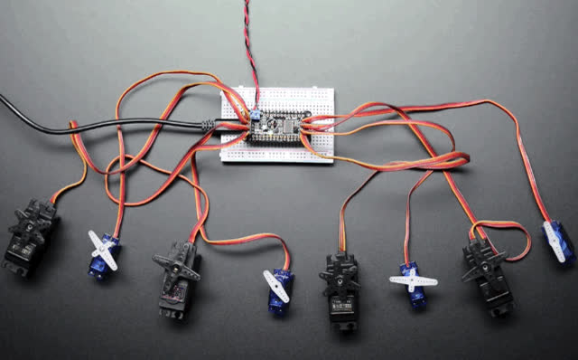
Adafruit Learning System
A 8 x servo party for your Feather!
idle grove
Anyone have an Intel real sense alternative
 digital pollen
Don’t know if this is the right channel but what are these things that come with breadboards for?
primal shell
They're often used as tie points for power supplies or other signals coming in from off-board. You can run a piece of solid wire from one to the breadboard, and then plug the incoming signal into the top with a banana plug.
 twin cove
And the rubber pads are for the underside of your board, to try and prevent it from making contact from whatever surface you're working on (desk, table, workbench, etc) and causing shorts
median smelt
primal shell
It explains on this page that servos can use a lot of power and make electrical ...
Thank you
idle grove
Anyone have an Intel real sense alternative
primal shell
I don't know, what is real sense?
idle grove
primal shell
I wonder if the SeeedStudio DepthEye would suit your purpose
idle grove
Probably but anything cheaper
primal shell
Webcam + structured light projector + software
idle grove
Ok
 sharp lark
If you’re using realsense, you might wanna spring for the d455
It had integrated imu and 2x the distance
It’s a little bigger and more expensive than the d435, but I’ve heard it’s good
The d435i is essentially the same as the d435, it just has an integrated imu
If you’re looking to do V-SLAM, the t265 is better because it does the computing for you, but it differs from the others because it’s not really a depth camera per say
 unborn gale
idle grove
Anyone have an Intel real sense alternative
unborn gale
idle grove
Anyone have an Intel real sense alternative
an old kinect (v1 or v2, depending on your requirements) should do everything you need
one important thing to remember is that the kinect v2 needs usb 3.0
idle grove
Ok thx
vernal sparrow
Has anyone in here worked with the JH-D300X-R4