#help-with-robotics
1 messages · Page 5 of 1
 proper summit
 elder lily
 weak kelp
@elder lily you could try to not move center part on your RC plane
as B-2 Spirit Stealth Bomber use similar how those BFS actuator fins work
so other wing fin go up when other go down when it turn
 terse sparrow
Looking for some help. Im using a adafruit motor shield v2.3 and i want to control two continuous servos with four push buttons with pull down resistors. Need help with the code.
 vocal star
@weak kelp Thanks for the pointer to the video. It could have been a little shorter, but overall pretty interesting. I've subscribed to the guy's channel.
 tardy breach
Can anyone help me with this. I cant seem to figure out what this diode(top left of picture) is and where to find a replacement. It says A2 E8 on the top.
 primal shell
Lots of diodes are marked A2: http://www.s-manuals.com/smd/a2
 south cargo
Anyone know if there is a way to solder an off switch onto a crickit?
 jaunty sable
Easiest way I know is to put it inline with the battery
Is anyone here a fan of the old RoboRally board game?
Surely I can't be the only person who has thought about putting together a batch of robots based on Crickit or Adabox 002 to do a live-action version...
 unborn hazel
Question about adding HC-06 bluetooth module to Crickit with CPX ; all 4 Servo pin sets will be taken up by the robotic arm. Arduino program already has code for bluetooth module and it works with Nano board. How would this module be wired to the Crickit? Any ideas?
south cargo
Thanks @jaunty sable . That's what I'm going to have to do. I never saw RoboRally, but a storyline with battlebots is totally something I'd watch.
 turbid trail
@unborn hazel You should be able to use the Signal I/O pins (3x8 connector) and find a couple that support UART.
 cursive dawn
@jaunty sable https://www.youtube.com/watch?v=5yPij5_XoLo roborally with robots (pretty sure I saw something more recent not that long ago, but this is what I found)
 sly sand
Hey everyone! I want to start experimenting with robotics for the very first time using an arduino. Can anyone recommend a good starting kit or should I just pick something interesting from amazon?
primal shell
A motor shield or a Crickit is a great way to get started. I'd avoid off-brand stuff with no support like you'd get from amazon.
sly sand
@primal shell Can you provide a link for a motor shield or crickit? Not sure what I'm looking at with these google searches
primal shell
Motor shield https://www.adafruit.com/product/1438
sly sand
I ended up buying an off-brand kit earlier but it's all seemingly basic components
Cool, added to cart!
primal shell
There are a few versions of the Crickit to suit different CPU modules. Here's the one for Circuit Playground https://www.adafruit.com/product/3093
primal shell
The motor shield is an Arduino shield and works fine with a generic Arduino. The Crickit also needs a CPU module of some sort to work with. While you could theoretically lash it to an Arduino, it's much easier to use a Crickit with the CPU it was designed for (there are versions for Feather, Circuit Playground Express, Raspberry Pi, and micro:bit). If you have one of these CPUs, just buy the matching Crickit. If you don't, you might want to pick up a CPU as well.
sly sand
I don't have a CPU. Does Adafruit sell those as well?
so I got the Crickit for Circuit Playground Express, so now I need to get the Circuit Playground Express right?
primal shell
You said you wanted to experiment with Arduino, so I was guessing you might already have an Arduino. If not, this is a nice one: https://www.adafruit.com/product/2488
The Circuit Playground Express is available here: https://www.adafruit.com/product/3333
sly sand
I have the Adafruit Bluefruit LE Feather M0
Ok I will add that on to my order. I do want to do CircuitPython
I know a bit of Python, but pretty much nothing about electronics, so I'm going to take an online course for cheap from udemy
primal shell
Ah, that's a Feather board, so you'd likely be better off with the Crickit for Feather than the one for Circuit Playground Express. https://www.adafruit.com/product/3343
sly sand
I
whoops. I'll probably just leave the arduinos to run the lighting rig I just set up, and try this CircuitPython thing with the CRICKIT and Circuit Playground Express
primal shell
Another approach, to get a bunch of useful parts at once is AdaBox 008, which includes a Circuit Playground Express, the matching Crickit, as well as other useful parts (motors, wheels, etc.). It's $80, but a handy way to get a bunch of useful parts at once. https://www.adafruit.com/product/3906
sly sand
Oh sweet! I'll get that instead.
primal shell
I can heartily recommend the Circuit Playground Express as a platform for learning CircuitPython.
sly sand
Ok, thank you very much @primal shell !
 old blaze
Hi all. When I want to power a rPi separate from the Crickit Hat, should the rPi be powered on first, then the Crickit power once the pi is on? Does the Crickit Hat automatically detect the pi already have power?
sly sand
The USB port on the Crickit HAT for the RPI is unusual in that it acts like a PiUART - allows a pass-through to the Pi's serial port, probably using CP2104 USB to UART bridge.
That's in addition to the use of this same USB port (again, on Crickit) to update Crickit firmware from time to tome.
The PiUART, in turn, provided a means to cut one of its traces, to prevent backpowering.
vout
The first question on my mind about the above image is why did they provide a connection for VOUT there?
The Crickit CPX has a bit more documentation, which is why I'm referring to it.
sly sand
There is a 5V path from DC 2.1 mm barrel, another from the USB port, and a third, at VOUT on this Crickit CPX.
quote
The Crickit power will also power the Circuit Playground Express or Feather so you don't need separate power for your microcontroller board (however, if you want to plug it into USB for programming, that's totally OK too!)
sly sand
Looks to me like the tiny switch on the Crickit HAT would be the master power switch, and would be the most preferred method to shut everything down at once (including the Pi).
Obviously most people want to shut down the Pi properly, so this would limit the timing of the use of this master power switch (if that's what it is) to sometime after the Pi was commanded to shut down, in software.
The way around that seems to be to power the Pi independently.
That way, just the robotics (motors and what-not) could be shut down, without also shutting down the Pi.
Because there is a shared ground that is well-bonded, between the Raspberry Pi and the Crickit HAT, this works just fine, if I'm correct in my thinking on this.
🔹 🔸 🔹
 frigid perch
So a long time ago my dad tried making a mop robot. I am thinking about revisiting his project for him. His mop robot had a ton of problems with slipping all over the floor. It didn't have any traction over the surface it had made wet. Any thought for how I could improve upon this? I was thinking of something that would dry the floors as it went but that would be hard. Thanks!
primal shell
Sounds sort of like a Zamboni. I wonder if you could plot a course so it didn't try to go over an area it had already mopped. I'm sure there are "paint itself into a corner" situations where it would have to wait until the floor dried, but it's what I thought of.
frigid perch
Is there a way to sense if the floor is wet? Thanks! @primal shell
 brave locust
two tracks of wire on a tire? sense the resistance between them?
primal shell
Hmm, that's a good question. You could use conductivity, reflectivity, maybe humidity? Or measure what you care about and maybe have a traction test.
Or do away with traction altogether and build a hovermop.
frigid perch
I like the conductivity idea. Sense the resistance between the robot and the floor lol. I will look into it. Thanks!
weak kelp

Amazon Web Services, Inc.
AWS DeepRacer is the fastest way to get rolling with machine learning, literally. Get hands-on with a fully autonomous 1/18th scale race car driven by reinforcement learning, 3D racing simulator, and global racing league.
Amazon Web Services, Inc.
AWS RoboMaker - Cloud robotics service that makes it easy to develop, test, and deploy intelligent robotics applications at scale.
weak kelp
some from reInvent
primal shell
Meh, not impressed with DeepRacer. And you can get Donkey Car today, for less money. http://www.donkeycar.com/

Donkey Car
An opensource DIY self driving platform for small scale cars. RC CAR + Raspberry Pi + Python (tornado, keras, tensorflow, opencv, ....)
brave locust
I wonder if you could get better tires with more weight for traction
weak kelp
some ROS as Microsoft have Rufus (ros robot) what use WinML
primal shell
Maybe use sucker tires for more wet traction?
frigid perch
Thanks!
weak kelp
octopus tires?
frigid perch
Maybe but I like the idea of a sensor to see wet floors so let's see how this goes.
brave locust
someone got an IR sensor handy that can take a pic of a mopped floor?
frigid perch
Too difficult to do that lol. @brave locust
weak kelp
@primal shell the deepracer is based on moster truck RC car chassis
primal shell
I'm not surprised, however the chassis isn't the important part to me anyway.
 spark cargo
Anybody here have any ideas for a locking system for arduino, like a door lock. i have some ideas but im not sure about my home brew
weak kelp
its more to easy start with machine learning with something real stuff
lets say you build a robot and train machine learning in the cloud and teach your robot as well
you could control your robot with crickit and using ROS like to connect with jupyter notebooks to teach your robot and then load those trainned models to your robot
@spark cargo you could think way to face detect for doorlock as door get locked when person go off and unlocked for person who is allowed to enter
for that need camera with ML model in board so it can detect faces
spark cargo
well im using rfid currently
and keypad access
im thinking about a motor controlled deadbolt type thing
for a safe
weak kelp
like solenoid?
spark cargo
yes
weak kelp
you could add face detection to it for additional security layer
spark cargo
i would have to reserch and learn, what sensors does it use
im sure i could find it online if you dont want to explain
weak kelp
there is now neurostick from intel what you put usb slot
spark cargo
how to do control data like that with arduino, wouldnt you need some type of external storage for that amount
or am i mistaken
weak kelp
you could test this http://customvision.ai
you could add pi for it what get camera detection so it call then arduino
spark cargo
hm
ive got to get this project figured out with what i have before i add more
i still need to do more reserch on keypads
weak kelp
there is some FPGA boards for arduino too
spark cargo
could it identifiy certain plant growth patterns you think?
weak kelp
if you train it to detect those then yes
weak kelp
you could do ml also from soil for plant growth as well with visual
 subtle spindle
Looking for participants for online robotic arm competition: http://roboarm2018.makerobots.eu/
 night star
can you guys pm me your favorit RasPi HATs?
 chrome grove
Does adafruit sell any battery fuel gauges at all such as the MAX17043
Or battery monitors
chrome grove
Or coulomb counter
primal shell
SparkFun has one https://www.sparkfun.com/products/10617 but I don't know of an AdaFruit offering.
chrome grove
Thanks I saw that. I also saw that they have one for the LTC4150
I was hoping for adafruit to have one to include in my order but oh well!
Will probably just build my own out of two high resistance resistors and a cap
primal shell
Not as fancy as a coulomb counter, but it works (I've done that in some of my projects too, and a few Feathers use that approach as well)
chrome grove
Yeah I have built a few which are quite accurate. I usually just choose the lowest tolerance resistors
chrome grove
Never mind. Happy holidays!
 dry flower
This may be the wrong channel, but it somewhat pertains to robotics. I am currently working on a GUI for a robot that will display data from sensors and other things. However, I am having trouble with the BNO055 sensor. This is the bug, https://pastebin.com/i7rVL7ah I have tried reinstalling the sensor module but this problem is still occurring. The sensor was working a couple of days ago but now it has stopped working, I followed the guide on adafruit exactly. Thank you.

Pastebin
 tame palm
So I am trying to setup a PS2 controller to wirelessly control a robot. I am using the ps2x library and have checked all the wires. I keep getting this error ```Controller mode not matched or no controller found
Expected 0x41, 0x73 or 0x79, but got FF
 alpine jewel
I think that that means that it cannot find the connected device, or one is not specified. I am not sure.
 hollow shoal
since when are ps2 controllers wireless?
tame palm
It came in a kit
It seems like something is not soldered correctly on the receiver end
 valid dirge
Anyone here has any experience with building soft robots? I’m exploring the idea of making soft robotic glove together with some doctors in the hospital for a spinal cord injury patient
 strong carbon
Spinal Cord Surgery with Robots. Thats scary and interesting.

 spice kelp
I just discovered that using a PS4 game controller as an input device on a raspberry pi is pretty trivial. Introduces lots of interesting possibilities.
 modest tulip
I am starting a project for an autonomous rc car and I need a magnetometer to keep track of heading. There are a couple different breakouts available. Does anyone have any idea about the differences between the following breakouts: https://www.adafruit.com/product/3463 https://www.adafruit.com/product/3387 https://www.adafruit.com/product/2472 https://www.adafruit.com/product/1120

The NXP Precision 9DoF breakout combines two of the best motion sensors we've tested here at Adafruit: The FXOS8700 3-Axis accelerometer and magnetometer, and the FXAS21002 3-axis ...

Add motion, direction and orientation sensing to your Arduino project with this all-in-one 9-DOF sensor. Inside the chip are three sensors, one is a classic 3-axis accelerometer, which can ...
If you've ever ordered and wire up a 9-DOF sensor, chances are you've also realized the challenge of turning the sensor data from an accelerometer, gyroscope and magnetometer into ...

He told you "Go West, young maker!" - but you don't know which way is West! Ah, if only you had this triple-axis accelerometer/magnetometer compass module. Inside are two ...
 crisp stone
@modest tulip Hello!
I did a project of an autonomous car a while ago, right now I have asked a question in the general section about it ,,, To be able to make a precise autonomous car you need a magnetometer that combines with the accelerometer ,,, I mean, to measure a direction in degrees you have to put the compass horizontal, but if the car is climbing a slope you need to compensate the inclination for a correct reading of the magnetometer, this is something that @abstract ice has to pronounce, if this is feasible and As you would do, I will attach my autonomous car code so you can take it as a reference, you can ask me anything, sorry for the translation, I am Spanish speaking, that code worked perfectly but without the inclination compensated, the car It oscillated until arriving at destiny by the data that loosen the IMU that they were garbage due to the vibrations.
sly sand
Anyone here who has ever worked with XBee radio modules? Or knows someone who has. I need help with configuring XBee radio to communicate between 2 devices. Please help
 viscid citrus
hi does anyone know if a system has been tried like this , Servo-hydraulic drive system idea for prosthetic hand just a thought i had made a quick sketch
valid dirge
@viscid citrus looks interesting, I had similar thought before, but I hit dead end when I try to packaging the drive system design, it’s simply too bulky to be implemented
viscid citrus
brushless motors in a rc servo type package with encoder maybe the way to go , just a thought , :}
valid dirge
@viscid citrus well, I would say motor size isn’t really the biggest concern, but it’s the fluid transfer system that’s giving headaches. I presume the easiest way to go is to use syringes, unless you want to manufacture your own hydraulic piston
The hydraulic piston need space to move, so if let’s say the piston length at full retraction is L, when it’s full extended you’ll have 2L in length
The space that you’re placing the hydraulic piston will need to accommodate for that 2L length
Another way to go around this is you can use a bigger piston at your input, trading the extension length for a bulkier piston
Both approach will end up with a huge drive system, if you compare it with other kind of drive system, like cables actuated and electric linear actuated design. That’s the dead end I’m facing here
primal shell
You could also use accordian-style actuators, which can be more compact (this is how spiders work).
 snow shale
I thought spiders worked through dark magic and evil intentions. Which could easily be confused with accordions, for all their similarities.
valid dirge
Hmm, accordian style actuators? I haven't seen that before, or maybe I had but I didn't know what it was called😂
primal shell
Same basic notion as an air lifting bag, but more constrained, like a bellows.
Seems it's actually a commercial product https://bellowstech.com/products/applications/actuators/
 idle valve
From an aptly named company.
 zealous dagger
Does anyone know about a suction cup that can be motorized? Something that can pick up light objects? Please @ me so I get notified thanks
primal shell
@zealous dagger Useful search terms are "vacuum pick-up tools" and "vacuum pen". Here's one likely site: http://www.techni-tool.com/Vacuum-Pick-up-Tools#!Vacuum-Pick-up-Tools
zealous dagger
@primal shell tysm that’s exactly what I was looking for
sly sand
Does anyone know what motors these are and where to purchase them?
I need them for a robot I am building
primal shell
I'm not sure that's a motor, it may just be a gearbox and perhaps encoder. There are flat "pancake" motors available, most of them are for spinning floppy and optical discs, but there are some made for robotics use as well.
sly sand
Do you know of any flat motors that are shaftless and circular? @primal shell
primal shell
A motor will necessarily have some sort of shaft, to support the rotor, but it can be a short shaft. Many motors are circular. Some axial-field motors are pretty flat. Generally the brushless type motors will be flatter, as they don't need room for a commutator/brush assembly.
 ancient lichen
@primal shell is right ... @sly sand Google "hollow electric motor" .. they have hollow shafts ... I don't know a thing about them ... I want so badly to link the Isaac Hayes song but it is probably nsfw .. Can you dig it?
 hidden jacinth
@sly sand I have taken apart some laptop cd drives and the circular "motor" appeared to be mounted directly to a steel plate with an incorporated circuit-board on one side. But i think ultimately it is simply a super-low profile spindle motor.
sly sand
@hidden jacinth Alright thanks!
 cosmic ocean
I am currently trying to use a planetary geared stepper motor for robotics applications. I am using the adafruit stepper motor hat for the raspberry pi. I follow their tutorial using the standard stepper motors but only the encoder on the back of my motor moves. Will this library not work with planetary geared stepper motors?
I am using the adafruit MotorKit and stepper library
primal shell
Normally planetary gear sets have multiple rotating assemblies, so locking one assembly sends the torque to another one. This means there are a lot of possibilities. It could be the encoder is connected directly to the motor and the gear assembly is simply reducing the RPM enough that the motion of the output shaft is slow. Alternatively, you may need to lock an assembly somehow (internal clutch?) to get output.
 iron egret
Anyone have experience with Feetech Servos. Debating between FEETECH FT1117M ($8) or something like a HiTech HS-85BB ($20) for an eye mech Im making. Currently using a slighlty weirdly sized Hobbyking servo and want to go with something a bit more universal for releasing the files
sly sand
" to all you prosthetics engineer's i thank you"
"maybe one day i will solder with my right arm again"
 quaint knoll
Hi!
idk if this is the right thread or if the arduino lane would be better but here ya go:
I have a robot actuated by 4 dc motors (w/encoders) on an arduino MICRO (I am using 4 interrupts 0,1,2,3) and want to add wireless control. I think I am leaning towards HC-05 BT module, but am open to other suggestions. Will the HC-05 work with only one interrupt (i am using tx/rx for encoder interrupts)? Can i use pin 7 for it, or would i need to move tx or rx to 7 and use that for my BT?
idle valve
@quaint knoll You should be able to use the HC-05 via software serial on whatever pins you choose. As far as interrupts go, I've never really used them combined with serial
sly sand
Would anyone have a problem if this channel was used for sharing project updates on robotics projects?
 modern pulsar
@sly sand That's an excellent use of this channel. Feel free to share project updates on robotics here!
sly sand
One of my favorite parts of robot building is the connectors. Sometimes it's finding unusual ways to use cheap ones, but when I have an excuse to use fancy mil-spec I love it!
sly sand
Here's the first pass at the motor mount, using a modified design from something I found on Thingiverse:
hidden jacinth
@sly sand turns out it was 3.5" floppy drives for laptops.
 ionic quartz
Would desktop version be different?
primal shell
A lot of floppy and optical disk (CD-ROM and DVD) spindle motors are that style, which is normally more or less an axial-field motor. They're pretty flat, produce low torque, and need an appropriate controller, as they're brushless.
If you remove the rotor from a motor like that, you'll see the stator coils, which will generally look something like this https://www.reddit.com/r/electronics/comments/4jewzv/pcb_mounted_motor_coils_in_a_floppy_drive/

reddit
230 votes and 8 comments so far on Reddit
sly sand
I completed the two motor mount modules this afternoon. Mil-spec connectors are great, but they are a pain to solder. I'd use the crimp versions but the crimpers are $500.
primal shell
You can get a passable radial jaw crimper for an affordable price.
sly sand
Interesting, do you have a link for one?
primal shell
This one was nicer than I expected https://www.ebay.com/itm/Crimp-Tool-Kit-Ferrule-Crimper-Plier-Wire-Stripper-800-Connector-Wire-Terminal/
 tidal ridge
@primal shell bad link
any insight on crimpers for jst xh connectors? thinking about this one. https://www.amazon.com/IWISS-Crimping-AWG28-18-Ratcheting-Connector/dp/B01N4L8QMW
primal shell
Erf, my attempt to make a more-permanent link didn't work (I guess it was session dependent). Here's the direct link to the item https://www.ebay.com/itm/112995349358
Amazon tends to sell dubious stuff, and sure enough, this article points out the Iwiss units are poor, and recommends the Engineer PA-09 (for AWG 32-20) and PA-20 (for AWG 28-18). https://iotexpert.com/2018/01/18/jst-connector-crimping-insanity/
You can get the PA-09 from AdaFruit for $50 https://www.adafruit.com/product/350. For reference, the recommended tool is the YRS-859, for over $1000 https://www.digikey.com/products/en?keywords=455-2569-ND
tidal ridge
why is a crimper a grand?? https://www.digikey.com/product-detail/en/jst-sales-america-inc/YRS-859/455-2569-ND/2298138
Order today, ships today. YRS-859 – Hand Crimper Tool Rectangular Contacts from JST Sales America Inc.. Pricing and Availability on millions of electronic components from Digi-Key Electronics.
primal shell
It's a lot of precision machining and probably a few exotic metals, special hardening procedures, testing, calibration, verification, etc.
tidal ridge
Looks a lot like this one - https://www.amazon.com/dp/B078WNZ9FW
never considered exotic metals. Yeah if it's from JST it should last a very long time. Never thought I'd see a manual hand tool cost that much.
primal shell
Looks completely different to me https://media.digikey.com/Photos/JST Photos/YRS-859.JPG
 tidal ridge
Should have clarified - I mean in comparison to the "Engineer" model
primal shell
Yeah, the Iwiss ones appear to be engineered to look like the originals. And they may basically work, but be a little harder to use, make poorer crimps (bad connections, wires pull out more easily, not gas-tight, insulation damage, etc.).
tidal ridge
Yeah they add laser etching to make them look the part
So what about this ratcheting style? https://www.adafruit.com/product/1213

Make cables and wiring harnesses with ease using smooth ratcheting crimpers. These precision machined crimpers will turn you into a pro, no more painful struggles with pliers and generic ...
primal shell
I get why professional tools are expensive, and I get why most people don't want to splash out that kind of money. There are times I go for the Harbor Fright version, and there are times I buy the best available. But often I find myself examining the middle ground, looking for something that's good-enough and that I can reasonably afford.
Those look similar to the Pololu ones, and the orange-handled ones you originally linked to. I don' t know who makes the blue-handled ones, but in general I'm comfortable buying tools from AdaFruit.
Amusingly, I just bought a (different) pair of ratcheting crimpers to replace some cheap old plastic squeeze crimpers that finally failed. The difference was amazing.
tidal ridge
in a good way I assume? I know when crimping ethernet connectors I do prefer the ratchet style.
primal shell
I really like the way the ratcheting ones work.
Weirdly, the non-ratcheting one costs more ($50 vs $35)
tidal ridge
now my robot will be so clean with beautiful wire harnesses!
primal shell
Nicer than this one I built, I'm guessing
primal shell
Yup, that looks familiar!
tidal ridge
raspberry pi with an arduino motor control board. i made wise choices....
weak kelp
have you checked ROS?
tidal ridge
I will once I get one of those $100 rplidar a1 units
weak kelp
@tidal ridge there is some porting to windows too on ros so you can choose when its that time
 tawdry verge
I'm having trouble finding the documentation for the NeoPixel interface on the Crickit/seesaw library for Arduino
primal shell
Some useful info here https://learn.adafruit.com/make-it-glow-with-crickit
tawdry verge
@primal shell unless I'm super blind (totally possible) there is no Arduino code in that article. Only CP and MakeCode
primal shell
Sorry about that. Looks like it's the same as the Arduino NeoPixel library, but you include #include <seesaw_neopixel.h> and instantiate it with c seesaw_NeoPixel strip = seesaw_NeoPixel(12, PIN, NEO_GRB + NEO_KHZ800);
tawdry verge
What is PIN?
primal shell
It's the pin the neopixels are connected to. For the NeoPixel connector on the Crickit, I think it's 10
tawdry verge
Thanks
 rustic raptor
I had this stuff for almost a year and now I'm getting to it...( if it matters the dc motors are a 1:90 all metal gears)
now if I can only get it ready to mow my lawn that will be growing in 5 months.
weak kelp
as Microsoft is porting ROS to Windows http://aka.ms/ros and ROS http://www.ros.org/ so if you want to make your robot to ROS
tidal ridge
seems silly when linux is the best option
weak kelp
WinML works great and I have seen demo of WinML using at ROS so it make some cool things, also opens up options for ROS
also seems the Windows IoT core isnt supported for ROS for Windows yet but Windows IoT Enterprise
 topaz compass
@primal shell @tidal ridge I know I am late to the conversation about crimpers, but I agree with the crapshoot level of quality on amazon tools. Of course they're all just Chinese sellers anyways. I've had two different Iwiss crimpers and they are both poorly made with bad precision.
Pretty sure I wound up returning both. I actually sprung for a $250 professional Molex crimper for commercial connectors. The craftsmanship is amazing on those tools meant for constant use. I see why they can charge so much.
Actually I take that back, it's just the ratcheting Iwiss crimpers I had issues with. I do have one set of non-ratcheting crimpers which actually aren't terrible.
tidal ridge
Thanks for the feedback. Very valuable as I still had it in my mind iwiss isn't total junk. Now I see its trash. I do find the rachets are more prone to issues. Maybe I'll get the plain version
topaz compass
Indeed. Despite my just knocking them, these are actually REALLY handy for doing tiny JST connector pins. If you don't mind double crimping by hand. https://amzn.to/2EgfqdG
I found none of the "2-crimps-in-one" ratcheting crimpers I found (or could afford) did a good job with the smaller pins like we use on drones.
 dreamy relic
Hey, is it "easy" to build a flying drone for caving exploration, something that can auto pilot, detect walls, explore and get back to start position ?
rustic raptor
(Poor lighting for pictures.) I think I might've done something wrong. (Its all about the learning curb.)
primal shell
Did you ... put a CPX on a Hallowing?
primal shell
Ah, that should be fine.
 gleaming elbow
does anyone know of a way to fix the garbage text and flashing LED produced by flashing the latest stable firmware build to the ESP8266MOD?
gleaming elbow
please DM me if you do.
sly sand
Hello friends! I'm a computer engineering student trying to learn more about embedded programming. I've spent the last few weeks diving into C and computer architecture, and I think I want to try to make a simple 4 wheel rover over spring break. I've been doing some research, and apparently the ARM cortex m3 or m4 meet industry standards and are a good place to start. Then I started looking for a development board, and things got a little overwhelming. I understand that in order to drive the robot's DC motors, I will need some kind of shield or motor drivers that are sold separately from the development board. I guess I'm really asking if anybody can suggest a dev board that runs on an M3/M4 and has sufficient IO, power, etc for a small robot.
primal shell
One reasonable way to get started would be a Feather M4 Express, along with a DC Motor Featherwing that can plug directly onto it to control your motors.
sly sand
Awesome I was checking that board out earlier but didn't know if it was enough for my application. Thank you!! Hopefully I'll be able to get started ASAP and share my progress/badger you all with noob questions. Discord is so cool for this kind of thing.
Thank you again
primal shell
It's a 120MHz M4 core, with a bunch of I/O and onboard power supply, additional flash storage, etc. I've found it plenty powerful for the things I've built.
sly sand
Excellent. Affordable too. Can't wait to start.
 hallow drum
Hi, has anyone gotten the good old HR04 working on a CPX and Crickit using circuitpython? been trying but i'm not there.
tidal ridge
what is an HR04? the ultrasonic distance sensor?
idle valve
@hallow drum There's a CircuitPython library for the HC-SR04 here: https://github.com/adafruit/Adafruit_CircuitPython_HCSR04

GitHub
CircuitPython library for controlling HC-SR04 ultrasonic range sensors - adafruit/Adafruit_CircuitPython_HCSR04
weak kelp
some if you want to get some power on your robots https://www.nvidia.com/en-us/autonomous-machines/embedded-systems/jetson-nano/

NVIDIA
NVIDIA Jetson Nano enables the development of millions of new small, low-cost, low-power AI devices.
ionic quartz
That certainly should help with humanoid robots like Inmoov
 fleet citrus
We tried a the old Jetson, not much more useful then a Android phone or raspberry pi for simple vision tracking
hallow drum
Thank you Andon for the info on the HR04, the problem I'm having is with the line "sonar = adafruit_hcsr04.HCSR04(trigger_pin=board.D5, echo_pin=board.D6)". I cant figure out what the board.D5 and board.D6 should be replaced with to work on the Circuit Playground Express and Crickit.
 main jolt
@hallow drum From the adafruit tutorial on the ultrasonic sensor The sensor's 5V Echo output cannot be directly connected to the inputs of a board like the Circuit Playground Express (CPX) but some trivial electronics can remedy this incompatibility. which means you need a level shifter board between the sensor and the board which is built for 3.3V logic.
Once you have that, try board.A5 and board.A6 or use the other free pins on the CPX.
hallow drum
I did add a voltage divider to the sensor, the problem is not with the electronics but the software. the board.xx command does not work with the cpx-crickit combo. I tried to modify the code in the CircuitPython Signals page found in the Cpx-Crickit page but can't get it to work.
main jolt
@hallow drum see if you can get the sensor working on the CPX alone with what you can gather from this tutorial. https://learn.adafruit.com/jack-o-theremin/build-the-circuit then add on the Crickit for other stuff. Sorry, I haven't worked with Crickit.

Make spooky, pumpkiny sounds this Halloween!
hallow drum
Thanks for the info caitlinsdad, thought of that using the same example but I need at least two or more sensors, so i have to use the 8 crickit -signal pins.
main jolt
@hallow drum Only me rambling here but some thoughts - Those sensors don't seem be I2C bus devices so if you were using multiples they can't be easily chained together. They are "slow" analog devices which need to be fired off and sense one at a time so they don't get confused with the noise of the other sensor signals. So if you are trying to use that to maybe triangulate and determine position or collision avoidance, you might be able to multiplex a bunch of sensors on one set of data pins for the CPX. There is a multiplexer/port chip that expands an i/o to act like more and be addressable so you can fire off one sensor, sense, turn it off and switch to the next sensor. The technique is used a lot in other projects like make a pair of eyes follow you as you walk by a painting or something. Good luck.
hallow drum
No reason to go to multiplexing when the crickit has 8 i/o pins,. A simple uno can handle this and has but i what to get it to work with circuitpython.
 chrome dock
@hallow drum In arduino you can call them as "CRICKIT_SIGNAL1", but no idea in circuitpython.
It's probable that hasn't been ported (yet).
I'm using a Crickit to drive a 5V mini-solenoid. Using 1000 as frequency, and 1.0 as the fraction, but the mini-solenoid is not pulling or pushing anything with any force I can feel.
Any ideas?
primal shell
Your solenoid is connected from 5V to one of the Drive outputs?
 halcyon mirage
building this project, and i totally forgot about a power supply... decently new at this... anybody wanna double check my reasoning?
5v, im figuring ~250mA for my arduino deumillanove, the hitec HS-311 servo i have says 800mA stall current, so im rounding up to 1A, then this nema17 stepper i ordered (https://www.amazon.com/gp/product/B01N30ISYC) says 250mA at 12V. im going to power it with 5v, dont think i need much torque, so im guessing 850mA for that too, rounded up to 1A again
5v 2.5A wall wort supply is what im aiming for. am i decently on target? or way off?
primal shell
Should be sufficient, but you won't get much speed out of that stepper either with 5V.
halcyon mirage
dont need speed or torque, its a space station pointer
1 step every minute or 2 im guessing
primal shell
Might work then.
halcyon mirage
thank you much. just wanted a sanity test on it 😛
primal shell
I'm fond of dash gauge steppers for small pointers.
halcyon mirage
if i had to buy a stepper, i wanted one i could use for an etch-a-sketch cnc. so i think this one will do
ill have to feed it 12v for that project, but thats a problem for future-smokkin
primal shell
Fair enough.
halcyon mirage
didn't need CAD for this project, the parts are already on the way... but i got bored waiting for the parts to get here, so i made it in fusion360
 primal shell
Looks like it could be the beginnings of an orrery.
halcyon mirage
lol
never got the chain working in fusion, but the gears have the correct 3:1 reduction
primal shell
Yeah, I liked the ghost chain. That would have been a lot of moving parts.
halcyon mirage
ooo! the 2 motors never need to run at the same time.
i think i can knock 1A off my req's
primal shell
That helps.
halcyon mirage
wakeup; do math based on current time; if it's moved more than 1step in the x axis, then take a step. if its moved more than 1step in the y axis, then take a step. sleep;
primal shell
The advantage of fine-grained control: you can make sure you don't activate more than one thing at a time.
halcyon mirage
yarr 😃
chrome dock
@primal shell Yes, one part to 5V and another to 1 in the drive outputs.
halcyon mirage
happy friday!
 median orchid
I've never done a robot project before but I got a crazy deal on one of these today: https://www.robotshop.com/en/bogie-runt-rover.html
I have a crickit and circut playground express from Adabox 08, and I was wondering if it would be possible to use that to drive this robot. The Bogie Runt has 3 motors on each side but this crickit seems made to control just two.

Rocker-bogie suspension
Rubber wheels to provide great traction
Includes Six 140RPM pre-wired motors
Easy assembly
The three on each side would turn on and off together, so I feel like they could be controlled as if they were two. But I imagine the crickit couldn't provide enough power for 3 motors. Is there a way around this? Or do you have advice on a better way?
median orchid
Ok, I looked up the stats of the motors in the kit, and i found their max load current is 250mA. And Crickit can do 1A for each motor output. So that means I could run 3 motors on each side safely with the Crickit right?
 bright bronze
The voltage is a bit short. The kit is made for 6.0-7.4VDC battery packs and the Crickit supplies 5V.
 surreal elbow
Don't know about those exact motors, but I'd imagine they are just the standard TT motors. I've run those off 5v without any problems. Assuming the currents you posted are correct, you should be able to run it off the Crickit that way.
One thing I would do is check the motors. It's not uncommon for there to be slight variations in speed on them. It's not usually significant, but may be worth matching them up so that similarly turning motors are on each side.
 obtuse rune
does anyone have the robojax arduino motor shield?
halcyon mirage
its been a while, and im having a brain fart. how can i test how much dc current my arduino project (with motors) is pulling?
i have a good fluke AC multimeter, but it doesnt have a dc amperage option. cant i test a voltage drop somewhere?
 proper cedar
you need a known series resistance to measure across
halcyon mirage
Fluke 324 True RMS Clamp Meter with Temperature, 400A. Great savings PLUS Free Shipping when you order today on Fluke-Direct.com. In stock, fast shipping!
thats the meter i have. no dc amperage option
proper cedar
choose a resistor that results in a small enough voltage drop that it doesn't affect your circuit too much, but is large enough to measure.
I would choose say 0.2V. You then need to estimate your current, maybe 2A or so? How big are your motors?
V = IR, so R=V/I. For 2A, this gives you 0.2/2 = 0.1R.
You then need to ensure the resistor can handle the power. Work out how much power your resistor is dissipating. P=I*V = 0.2*2 = 0.4W in this case. Therefore, you need at least a 0.5W resistor, and probably a 1W resistor so it won't get hot enough to burn your fingers
Hmm what is the smallest voltage range that meter can measure? It looks like it is only 600V to me
halcyon mirage
2 decimal places, in dc. i can measure 0.33vdc from a hot water heater's thermopyle
rated as high as 600vac
proper cedar
OK great, then choosing a resistor that gives you 0.2V should be OK.
Estimate what current your motors might take max, then choose the resistor based on this.
If you don't have a low value enough resistor, put them in parallel to make the right-ish value.
This also shares power between the resistors, so they won't get so hot.
halcyon mirage
also...
arduino + motor shield. stepper motor is 350mA max (will see nearly zero load). servo motor says operating current draw 180mA, full load 800mA (will see nearly zero load)
the 2 motors will never run at the same time. its for a space station pointer eventually
proper cedar
guess 1 amp or so then max
halcyon mirage
rotate the stepper into place, release it. rotate the servo into place, release it
wait 1-2mins, see if we need to move 1 step. if so, move the stepper and release. move the servo and release
i just wanna see how much current im pulling
proper cedar
Hmm your peak current usage is very short then. Might be hard to measure, as your multimeter does not update very fast.
halcyon mirage
i have an oscope too. but im a noob with it
proper cedar
With the o-scope, it gets more dangerous, as its much harder to measure voltages "across" components with an oscilloscope
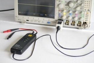
In an electronics lab, a recently-built advanced oscilloscope is one of the more costly test instruments. To protect this investment from instant
halcyon mirage
found it in the dumpster at work, when the company next door was moving out. it had 2 broken knobs. i used epoxy + made sure they were set correctly as the glue set. i now have a pretty good scope lol
yea, ive read those. which is why im not using it yet lol.
proper cedar
Also with steppers, they actually use more current when not moving if they are still held in position
halcyon mirage
dunno if i could do it correctly yet. ive played with it a few times, mostly watching audio from my laptop's headphone port
wait, what?
oh yea
i dont need it to hold position
move to the next step, and release the motor. it will have nothing pushing against it
doesnt need holding torque
proper cedar
good, that will keep it cool to the touch
halcyon mirage
proper cedar
to measure with your multimeter then, modify your code so it spins continuously. Just one step will be too short for your multimeter to see
halcyon mirage
yarr. i do want to test it at max. so ill make it spin hard, maybe even both motors running at the same time...
proper cedar
yeah go for the worst case, good way of double checking.
Often, acceleration may take more power than constant speed rotation.
halcyon mirage
12v 3.7A dc supply coming into the motor shield, which will give the stepper 12v. it feeds into the arduino's vin pin, so it does the 5v regulation itself. (its gunna get warm, i wish i had a 9v supply)... the stepper power comes from the arduino's 5v pin, which seems wrong to me... but all the adafruit examples use it, so it should work?
i have the parts to rewire it if needed, but lets see how the 'hello world' things go
proper cedar
What stepper driver shield do you have?
halcyon mirage
derp. the servos power comes from the arduino 5v pin
proper cedar
Yeah the servos will need that, won't like 12V at all
halcyon mirage

Control servos, steppers and DC motors with an Arduino!
warning! this is the ancient one! you prolly have the new one...
yea i have the old one
proper cedar
Are you sure? Its 7 years old
halcyon mirage
stepper motor is powered from my 12v supply. it also feeds that 12v supply into the arduino (if i want it to, and i do). the servo motors are powered from the arduino's 5v regulator
yes im sure. its sitting in front of me, and i built it like 5-7 years ago
ill take a pic
proper cedar
Its OK I believe you
It should be OK to power the servo from the Arduino 5V, as there is a capacitor on board to smooth things out a bit. The Arduino regulator might get quite warm, but that's OK as it will turn off safely if it gets too hot
halcyon mirage
good to know
proper cedar
By the looks of your video, you are not putting very much load on the servo either, so it won't draw too much current compared to the peak, unless you move it very fast.
Either way, you need an inline resistor to measure the current draw with your voltmeter. Are you OK with how to do that now?
halcyon mirage
neither one of them will have much of a load. i can release the motor entirely, and it will hold
proper cedar
Are you happy with how you can measure the current?
 proper cedar
yes, you need to calculate the value using the equation I gave you, and check the power is OK so it won't burn
And if it will, you need either a higher power resistor, or multiple resistors in parallel.
halcyon mirage
got it. thank you so much
i do have plenty of breadboards, and a pile of resistors. i can make it work. ill use ur equation to choose the right value, and make sure i can dissipate the heat
proper cedar
No worries, let me know if your finding the maths a bit tricky and I can do it for you.
Its easier if you know how to do it yourself though, as then you can check against what resistors you already own.
Great
halcyon mirage
im an AC electrician by trade, but i like programming + electronics as a hobby. ive played with arduino for years, but mostly blinking leds. not much exp with motors
im afraid of pulling too much current and letting the smoke out. i'd like a way to test it
i think i got it, thank you sir
proper cedar
No worries! You could always use a fuse as well, they work at low voltages too 😉
Polyfuses in particular are quite nice, as they are self resetting
tidal ridge
slip ring for continuous motion?
halcyon mirage
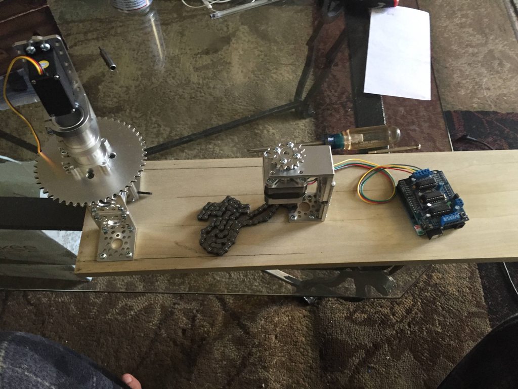
got the chain+sprockets hooked up. the chain is fiddlier than i thought it would be
at first, the motor wouldnt even spin. too bound up. took me a bunch of fidgeting to get everything working smoothly. hope it holds
think it may need more structure, so it cant flex

 primal shell
I suspect that's one reason cog belts are popular.
halcyon mirage
i think ur right
too late now, and i cant redesign to make the chain sit vertically. so ill tough it out
i guess
primal shell
Once you have it dialed in, it should behave, it's just annoying getting it there.
 hexed rock
on a three-wheeled robot, with two rear wheels differentially driven (i.e. steered by the rear wheels), for the front wheel is a single pivoting wheel, with the pivot ahead of the wheel axis, work well? Any guidance on how far the pivot should be ahead of the wheel axis? contemplating rotating in place, it has to be a little ahead, but can't get my head around the affect of various amounts
primal shell
It generally works well, but there's likely to be some slippage. The farther the third pivot is from the centerline of the driven wheels, the more drag it's likely to apply, which will tend to move the axis of rotation.
surreal elbow
Have you checked for three wheeled bike building info? I'd imagine the math for the angle should be very similar.
nevermind, I think I read that wrong.
hexed rock
I think you read it right. The problem with bikes is that they are actively steered. For the kind of robot I'm envisioning, the wheel just kind of follows, hence why its axis of rotation vertically needs to be ahead of its horizontal axis, so it will swing in the direction of travel. Or, I guess I could put a motor on the third wheel? Wouldn't be that hard, would take a little to calibrate it so nothing dragged, but doable.
primal shell
That's how my lawn tractor works, the steering wheel both pivots the front wheels and adjusts the drive proportion to the rear wheels.
 versed solar
I just picked up a few ItsyBitsy M4s and am excited to get rolling with them. However, I'm having trouble finding detailed specs for the board. For example, right now I want to know what sort of protection (if any) there is on the USB port power. Is there any short circuit protection to avoid blowing laptop USB ports?
The best "spec sheet" I can find is this intro doc:
Am I blind?
versed solar
Ok... Mouser has the same specsheet for it, so that is probably the best thing available.
versed solar
Aha! I didn't realize that these boards were open hardware! 😃
So the answer to my question is: V_HI has no short circuit protection whatsoever (unless the USB output itself has it in laptops?), but the 3V3 output has the protection from that AP2112K, which seems to be at least (?) 600 mA.
primal shell
Most quality laptops have a polyfuse or smart circuitry to limit current in USB ports.
 queen burrow
Hi, new here. I don't have a specific project or question to ask about right now, but I did have a general question. Across all of my current and future projects, there are some patterns that form regarding all the issues I keep running into, with no clear solution. The problem is this: All of my projects require a "brain" (micro controller, and arduino, etc), but they all also use outputs (motors, solenoids, and custom loads etc) that require voltages and currents that both cannot be supplied by micro controllers and will harm/damage/destroy said micro controller. In addition, most of my projects are wireless, thus require a battery. My question is, is there a general solution to this problem? I feel it is quite common, but that it is so common, I can't seem to find consistent and non-confusing help because most people have figured it out. If not, can someone give me an example of a complete project that has solved my issue(s) in one case, and we can piece it apart from there? Is there a basic kit for this; Particularly for a large number of inputs and outputs?
versed solar
@queen burrow Generally you can have two power supplies. One for your "brain", and one for your motors/etc. Join the grounds so that you have a common reference point, and you are good to go. Current flows from the two supplies should be clearly distinguishable, with only the ground as a common point.
If you just want to use as single power supply (as with many projects). you just need to make sure that your high current things (e.g. motors) are driven directly from the supply/battery, and so is the "brain" (in parallel). This way the high currents do not pass through your microcontroller. Microcontroller outputs typically can't drive much current... generally just tens of mA.
In the single supply case, resulting junk from high current loads like a motor (where junk includes stuff like sagging supply voltages, inductive kickback, etc) that gets onto the supply rails can certainly affect the "brain" side of things, but that is what a good regulator is for, and why you need to expend some effort to quiet down your loads (e.g bridging capacitors and flyback diodes across your motors).
As an example of the single supply case, you can conveniently see that VHI output which is in place to provide the source voltage to stuff like motors, while the onboard microcontroller gets the regulated 3.3V output (+3V3) from that AP2112K. Also note that the VHIpath still goes through one of those MBR120 diodes, which can only handle 1 A in total. I f you wanted to pull more you'd have to connect directly to your VBAT (or VBUS, which likely can't give much).
Hopefully that helps?
queen burrow
@versed solar I understand the use of the diodes, but I don't understand the use of the capacitors. I have a signal processing background but I am rusty and out of practice. I think my issue with that is that one capacitor across a motor is not sufficient for signal noise reduction, and in the case of controlling outputs, it also seems overkill and unnecessary.
Also, what if outputs require very high voltage?
Also, what if I want to control 18 heavy duty motors, servos, or solenoids?
primal shell
Generally there will be (at least) two power systems: one for motors and one for logic, although they can both be derived from a single source (popular for battery operation).
queen burrow
@primal shell And... I do that how? The suspense is killing me. I've been trying to tackle this for a few years now. I am suffering a lot of embarrassment trying to ask this here. I know this is very trivial for a lot of people.
primal shell
Power management is anything but trivial, and a continuing issue for lots of robotics projects. One approach I've had good luck with is to use a battery pack the produces the (higher) voltage I'll be using to power my motors, and use that directly for the motor drivers, and regulate it down to 5V to distribute to the logic (which, in many cases, regulates it again down to 3.3V, but the double-regulation can help enormously with noise, brownouts, and the like).
I'm fond of using a UBEC like this one https://www.adafruit.com/product/1385 to get a nice 5V supply from a higher voltage without a lot of waste and heat.
queen burrow
@primal shell Not sure where this device should go. Do you place it between the battery and the arduino, or the arduino and the output? Another problem I run into is finding a micro controller that has enough inputs and outputs to run the number of loads I want, while also being a device I have the knowledge to use (a Raspberry pi is out of the question). It gets worse when (depending on the load) it can take 3 to 5 output pins to control one load correctly. What if I want to control 20 stepper motors for example, with forward-backwards control and angle reading? An Uno and a Mega aren't going to cut it, as far as I know.
primal shell
It would go between your battery and the power supply input on your Arduino.
While it can take a few pins to operate a stepper motor controller, those pins can often be shared between more than one controller. For example, for I2C based controllers, you only need 2 pins for several devices. For SPI based controllers, you need 3 pins for the SPI bus itself and one more pin for each device you're controlling.
You can also use devices known as multiplexors or expanders to get more I/O pins without switching to a bigger controller.
Another approach is to use more than one controller: you can have one controller that operates a few motors and monitors position feedback, and another controller that tells it what to do.
queen burrow
@primal shell Really? Those options will work even if each motor is doing something completely different?
primal shell
It can, the limiting factor tends to be timing. If you need tight synchronization among a lot of motors (for example, stepper motors in a CNC arrangement), it's harder than if you're operating a rolling robot with an arm.
It also matters how you're operating the motors. DC motors are normally operated by PWM, steppers are often run by controller chips that manage the timing for you, but sometimes are controlled at a low level with "step" and "direction" inputs that have to be sequenced by the controlling processor. That last can be demanding.
queen burrow
@primal shell I would say tight synchronization is very important.
primal shell
Then you may want to look at either dividing the load (several controllers) or using a more capable CPU with lots of IO (like the Grand Central). You might also look at how things like GRBL are implemented (which use an Arduino to run several motors in synchrony).
I'm eyeing a Grand Central myself for a somewhat related problem: I want to replace the brains of a pinball machine and need reliable real-time control of lots of things (lights, sounds, bumpers, kickers, etc.).
queen burrow
@primal shell Oh, good thing it's in the product store. I felt like searching the internet for "Grand Central" wasn't going to end well.
primal shell
Hmm, good point.
queen burrow
@primal shell Well, it uses Arduino. It's also good for if I do eventually get to the point of learning Python. It reminds me of a product released on Sparkfun about a year back. It was a huge board built specifically for what we have been talking about and it had a stackable accessory that can be bought to add more and more outputs. It was advertised as one of the most extreme products they ever sold. I didn't get at the time because I was still focused on making a network out of xbee's and metro minis.
primal shell
You can program the Grand Central using the Arduino IDE, but if you want to stick to the AVR CPUs, you may have to either use smart motor drivers, or split up the load across multiple boards.
Hmm, not sure what the SparkFun product was, but guessing T'Rex, Rover, Stepoko, or perhaps Motor Plate.
weak kelp
if you want to test your JetsonNano with PiCam https://www.youtube.com/watch?v=dHvb225Pw1s

Let's hookup a RPi Camera to a Jetson Nano Developer Kit. No fuss involved. 0:55 - Install Camera 2:46 - Initial Test 4:47 - Code sample demos Full article o...
 austere marsh
With the CPX crickit i've noticed under powered issues when driving 2 servos with 3 x AA new alkaline. Should I need 4 x lithium ion AA? It works fine if there's microusb from the laptop to the CPX with the battery pack on the cricket ie green happy light is on, then gets red flashing with just the 3xAA alkalines
primal shell
3 AA is a little marginal, but it might work if you add some bulk capacitance to ride out the spikes. Alternatively, you could go to 4 alkaline AA. I'm unsure about the lithium cells, some of those are 3V, so you'd only need two.
austere marsh
Thanks @primal shell I tried 4 x AAA alkaline but the happy light started flashing red so was unsure if that meant over powered
sly sand
i use a 18650 cell to ride out spikes on the pi.
primal shell
Hmm, you're right: I had misremembered the specifications: it is unhappy if it goes under 3V or over 5.5V, so 6V won't work. Perhaps either stronger cells (C or D instead of AA) or some capacitance would help, otherwise you may need a regulator of some sort.
tidal ridge
anyone know where to find micro servos with more than 180 degrees of motion? I can find continuous, but nothing > 180
I guess im just going to solder some resistors on the servos I have to increase motion

Easy and cheap way to make a nice 180 degree throw for a Pan servo for FPV
 upbeat bloom
I am looking for a sensor, maybe a board, not sure here to monitor the battery level, and if it is above a certain level of charge, to run a routine, and if the level is below the set thresh hold just keep charging (from solar panel.) If I am thinking correctly, the chip/sensor would sit between the battery/charger and the microcontroller/feather/Metro/etc. Any idea what this is called. Not specifically for a robot project, but wasn't sure where to ask. Thanks.
 grizzled hound
if you already have a charging circuit, there might be an indicator/output on it for charge level. if it has a 'charging' status and a series of outputs for 'level of charge' you could pretty easily build some logic that is only on when its not charging and the charge level is high enough
otherwise you might try monitoring the voltage if you know what the voltage is when charged. eg if its 4v when mostly charged and 3.5v when too low you could use that
it depends a lot on your exact battery setup and charging circuit though
primal shell
There are 270° servos out there like this one https://www.dfrobot.com/product-1177.html
tidal ridge
@primal shell Thanks, but those are what I'm naively calling "standard" size. I need the "micro" form factor like the SG90
primal shell
Sorry about that, I missed the "micro" part. I did learn about interesting servos looking around (there are servos that can make 1, 3.5 and 6 turns out there for "sail winch" duty, which I didn't know), but I'm not seeing any micro servos with more than 180° travel.
You may be stuck modifying a servo, or adding gears or levers to get the action you want.
tidal ridge
yeah i considered continuous rotation and adding 2 limit switches but complexity is annoying. I think adding resistors to the potentiometer is the cleanest option
i have this cool pan tilt, but the sg90 servos now have weak range of motion
primal shell
Interestingly, it's a geared design, I hadn't seen that variant before.
tidal ridge

Pan tilt mechanism with ball raced pan platform & geared tilt for higher torque.
Available on my website:https://www.3dprintcq.com/product-page/geared-pan-tilt
Australian delivery only, sorry.
The base with the mounting tabs was from a different remix, but oddly enough it's still not tall enough and the servo hangs out the bottom..... so probably going to have to make it even taller
primal shell
That's a neat little design, even if it does need some fine-tuning. My pan-tilt brackets are simple sheet metal pieces, or this little injection-molded plastic one https://www.adafruit.com/product/1968
primal shell
Pololu has a nice sale for National Robotics Week: https://www.pololu.com/nationalroboticsweek2019

In celebration of National Robotics Week, we are discounting Pololu robot kits and their accessories 25% (limit 3 per item) and offering 20% off all other Pololu-brand products with an “Active” or “Active and Preferred” status (limit 5 per item). The sale runs through...
tidal ridge
Pro tip with pololu is they announce products on their blog and have coupon codes. Even some codes many months old still seem to work!
austere marsh
so yeah the crickit works fine with multiple servos using 4 x AAA NiMH
I should have gone back and re-read the doco rather than relying on memory
primal shell
That's 4.8V nominal instead of the 4.5V nominal from 3 alkaline cells, which gives you a little more margin, and I vaguely remember that NiMH cells (even little AAA ones) are fairly low impedance* which will help avoid brownouts during current spikes. * Although not as low impedance as NiCd or lead-acid.
tidal ridge
Adding resistors to my servos definitely increased the range.... and also immediately stripped the plastic D piece for the potentiometer. The catch is you definitely cannot put the full range PWM signal because one way will always be continuous motion.
Added 1.5k to both vcc and gnd of pot
primal shell
That's unfortunate, as it otherwise looked like a reasonably clean approach.
tidal ridge
it's fine as long as you stay within a smaller PWM range than normal. usually it's 500-2000us with 1500us as midpoint. I have a servo tester and just cranked it full in both directions. So long as you stay in the middle you're actually in pretty good shape. the typical midpoint is 1500us, but this also skews that midpoint. I suppose one approach to extend range more safely is to put a single resistor on just the VCC side so it will still go to 0v and stop. Effectively shifting the mid point and enhancing range. I think I'm going to get the mg90 servos with metal gears and see if it fares better. Overall this approach seems to work perfectly.
tidal ridge
queen burrow
Is there any hardware that something like the Metro Mini can power by itself?
sly sand
Yup seen 2 many of those servo's dead
primal shell
@queen burrow That's a fairly broad question. Do you mean the Metro Mini's on-board regulator, or via an I/O line? And "hardware" covers everything from LEDs to motors.
queen burrow
@primal shell Hardware as in anything that can move. So motors, actuators, solenoids, servos, etc. I didn't want to exclude anything I am not aware of. Not sure what you mean buy I/O line. But yes, with its own on board regulator
primal shell
The Metro Mini doesn't provide much in the way of power. Its on-board regulator is only capable of 150mA of output, which won't drive much. The FTDI chip also provides 3.3V at 50mA, enough to light a couple of LEDs, but that's about it.
150mA isn't enough to run even a tiny motor like https://www.adafruit.com/product/3871
In general, if you want to run things that move, you'd need a separate power supply (which can be the same one that's supplying the Metro).
Motors generally aren't picky about voltage, so they don't need a regulated supply, but they do need some current capability.
queen burrow
@primal shell That last bit is actually really helpful info. I was always concerned about burning out my motors as well.
primal shell
Motors are pretty robust in general.
queen burrow
@primal shell So a I have a lot of those quarter sized CD player brushless DC motors. Can it run those? Also, are the power requirements of the motors I mentioned, low enough not to harm the Metro mini if I power them directly and make a direct control signal connection to the board?
primal shell
I don't know what those draw, but likely more than the on-board regulator can supply (the digital outputs can't run motors directly anyway, and that's probably a brushless motor, so you need to phase its supplies to make it run).
 cosmic badger
CD motors are round 3.3v
primal shell
I was wondering if the 150mA the regulator can provide was sufficient.
 formal saddle
anybody here got a tutorial or a place where I can make my own parts to create my own servo steering? I want to use an arduino robot car chassis but add my own type of steering into it , however I have no idea where to find parts that include small metal rods, hubs and connectors so my servo can steer or turn the direction of my wheels.
tidal ridge
Modified servo final product. First time soldering SMD turned out OK.
@formal saddle check this out: https://hackaday.com/2019/04/09/nearly-entirely-3d-printed-rc-car-is-4wd-fun/

Remote control cars can be great fun, particularly if you’ve got a spare carpark or dirt lot to hoon them around. Any good hobby store will have shelves stocked with all manner of vehicles &#…
formal saddle
thank you
 desert maple
Anyone know if Vex 393 motors will work with a L293D ic controlled by a raspberry pi?
hexed rock
Well, the stall current on a 393 is listed as 4.8A
The output on the L293D is listed as 0.6A with peak 1.2A
So .. it will work, but if you load the motor much, the chip will likely let the blue smoke out.
Going by the specs, anyway
desert maple
Ok thanks
 regal gull
What are the advantages/disadvantages of using 360 servos vs. DC motors?
primal shell
For servos, the controller doesn't have to handle much power, it just tells the servo how fast to go (via PWM). For DC motors, the controller has to deliver the entire motor power, and can thus control the speed (and direction, if the controller supports it) using variable current or PWM.
regal gull
I understand the differences, but in what situation would you use one over the other?
sly sand
Torque!
tidal ridge
Try both!
regal gull
k, thx for the quick replies!
hexed rock
Thoughts on attaching the drive end of a SG90 servo to a 3D-print? The teeth in the horn are just too small to FDM print. Gluing in a horn is kind icky, and well, using screws ... they gonna be really really small and hard to get just right. Is there some simple way for this that I am missing?
primal shell
Make a recess to fit the horn and clamp it in somehow?
tidal ridge
Don’t they come with screws? Usually they come with the proper pieces and screws to attach to the horn. Then you can screw your piece into that more easily.
Are there any servos that are around $20 that don’t destroy themselves over time?
hexed rock
Yah, but getting the hole right for the screw to go into is non trivial; it is unlikley to print right at that size, and I don't think I even have a drill that size.
tidal ridge
hexed rock
Well, I could use one of my PCB drills...
The SG90 has really tiny screws (well, really tiny everything)
hexed rock
It's not ... elegant. I mean, for sure, it'll get the job done, I just thought there might be some magic out there 😃
primal shell
The horn recess trick is illustrated here https://create.arduino.cc/projecthub/StaffanEk/skating-robot-2adf1a
sly sand
I should just shove a servo in a closet somewhere where I can't hear it and run it until it breaks, with a .. elapsed time meter on it. ;)
Even if it were a flying (model) airplane I'm thinking the number of hours' use would be very low.
In the rare event your plane is not crashed or lost, the servo will fail at some point in the near future, would be my (wild) guess.
I've never priced out the high-end stuff (if it exists).
tidal ridge
mine was taking constant abuse with max torque and such. i figured any decent servo would have mosfets rated for the stall current. and maybe bonus features to shut itself off before damage
primal shell
There are servos like that, but they're not the $8 specials you see everywhere.
sly sand
OH I just assumed raw mechanicals would break down such as bearings and whatnot. Or stripped teeth on gears.
If you pay USD $150 you expect it to work for a while. ;)
primal shell
Yeah, for that kind of coin, I would want some circuit and mechanical protection.
tidal ridge
I'm in the ballpark of $17 currently - working my way up to find the best value. The $17 servo beat the $5 servo so far... will report further progress 😉
primal shell
Please do, this is useful info.
 humble shuttle
Has anyone tried (and/or succeeded) and making a sphere-bot using Cricket yet?
As far as I can tell, the hardware is all there (stepper and servo drivers) but I don’t know enough yet about the firmware (still digging) to know if it could be run on a Circuit Playground Express or not.
https://www.open-electronics.org/spherebot-reloaded-customize-your-xmas/

Let’s create a plotter to decorate Christmas Tree balls with writing and drawings. Christmas is coming you dusted off your xmas tree and decorated it: everybody try to make it different, buying new decorations and balls of different colors. Well, if you are looking for some...
primal shell
I'm guessing a CPX would have plenty of horsepower to run it.
 tired pawn
@primal shell where should I get started on real-time processing? I bought a beaglebone again and it’s functions are pretty good but what is making it real-time processing vs arduino metro or pi cards?
primal shell
It's a little hard to nail down what constitutes "realtime processing". I tend to think of things like Arduino as realtime, as they don't have an operating system to get in the way, and can respond quickly to information. Beaglebone has an advantage too, as it has separate CPUs which can be dedicated to tasks, giving consistent fast turnaround. The Pi isn't so good at this, as the operating system can cause unpredictable delays in responding to inputs.
Unfortunately, I don't have any resources to hand to point you to.
sly sand
Maybe look at RTOS and decide what that is, first.
If you have a latency-critical application (like RADAR) you cannot have delays or you will lose data (and the target that you're painting with radar).
Other applications are more asynchronous and while they still need to meet a production deadline, the instantaneous results may be incomplete and may also not depend on other instantaneous results. They may be done in parallel, in a batch, and the like.
My guess is those ideas may be involved in evaluation of a system as 'real-time' or not-so-much. Just a guess.
To me it's just a buzzword.
Not only is your subjective experience of reality not real-time .. but it is also not historically accurate.
Your brain produces a narrative that's only peripherally related to objective inputs it receives from the environment. ;)
tidal ridge
Real-time is best done via arduino
Beagle real time cpu is basically an arduino-like cpu baked into a pi-like cpu. But I don’t think the beagle real time units are as easy to program as an arduino.
primal shell
True: Beagle is more powerful (its real-time CPUs are more powerful than an Arduino, and I think there are two of them), but it is also more complicated to program.
tidal ridge
on the flip side, raspberry pi 3 B+ is more powerful on the linux / general purpose side because it's quad core vs beagles single core
 ebon mantle
https://www.youtube.com/watch?v=FlsB8ve67Cs
i want some wheels like that

Pledge your support to keep FUN loud, live and independent for $1 and get Patreon only benefits including uncut full episodes! Go to https://www.patreon.com/...
primal shell
Looks like an updated version of the one in tin toys where one wheel was mounted on a rotating assembly.
formal saddle
anyone has a link to buy a good lipo battery for arduino? I need a steady 7v to 9v supply for my 4 dc motors, 9v is not enought as the l298n driver somehow outputs less than 7v with 9v input. 11 v should suffice and it has a regulator.
also, on a mega 2560, besides 2 to 13 pin, which other are pwm pins? with my current setup I nrequire about:
14pm pins,2 analog in, and 1sda and 1scl
which means I need 2 extra pwm pins
 lean cloud
you could look at hobbyking lipos
formal saddle
ok
lean cloud
hobbyking make good quality 11.? lipos that i use in some of my RC cars
formal saddle
also, quick question, is there a way to output data from the arduino (like a variable or something) to a raspberry pi?
lean cloud
you can implement a tx/rx serial relatively easily
formal saddle
ok will check hobbyking, I am lookingfor something really really budget, (10$ or under 20$ with a charger) . just meant to drive the dc motors, the rest of sensors will be driven by voltage given by arduino or raspberry pi
tx/rx serial would allow for example send a parameter to the raspberry pi, I imageine I would have to configure the raspberry pi to listen for the variable being received right?
lean cloud
yeah, you can use "screen" in linux, you'll need to read up on enabling hardware serial on the pi
formal saddle
ok, ok.
lean cloud
I personally feel it's easier than doing USB serial on the pi
formal saddle
THen my issue would be using other sensors on the raspberry pi
lean cloud
you'd still have the i2c and SPI buses available
formal saddle
probably easier, but then I would be powering the arduino from the raspberry pi
i2c and spi buses , ok, what about like programming? I am used to programing on teh arduino, easy to set up pins, pwm and analog in, and other stuff, but onraspberry pi no idea how to deal with the gpio in a way I could use for example some sensors from the arduino
lean cloud
if you've used i2c sensors on arduino it's not too different in pi/python
but python is quite different from C#
formal saddle
hmmm
i havent used pythong at all
only c,c++ and java so far
and some assembly
welp, time to learn python
thanks for the help
lean cloud
no worries
rustic raptor
Huh, anki is shutdown? Where did they go wrong?
 ashen mural
So I just bought a couple of these from amazon Onyehn 2Pcs 1.8v 3v 5v 6v 7.2v 12v 2A 30W Low Voltage DC Motor Speed Controller PWM 1803BK 1803B Adjustable Driver Switch 2 Pack https://www.amazon.com/dp/B07FLJ6ZHQ/ref=cm_sw_r_cp_api_i_4ELYCb49SFEKF
I’ve got a project where we just need to rotate a motor at variable speed. I’d much rather buy this type of thing from Adafruit... anyone know if they’ve done anything like this?
primal shell
Most of the motor shields, H-bridges, etc. available from AdaFruit will let you use PWM to control motor speed.
If you already have a CPU in your project, you can use that. If not, pretty much any of the small CPUs would be able to do so (read the value from a potentiometer and generate PWM to control the motor speed).
 steep loom
Hello guys, many thanks for the inspiration! I have rather limited access to M2, M2.5, M3 screws, has anyone used a 3D-printed alternative and was satisfied with the results?
The project isn't the final prototype and would surely require some modifications therefore glue isn't that good of an option for me.
idle valve
@steep loom If you're in the US, Lowe's typically has M3 screws. I wouldn't try to print a threaded object that small, it likely wouldn't work.
 mellow willow
I swear I came across documentation in the last couple days to invert servo direction in circuitpython but I can't seem to find it now. Anyone know? (without creating a function)
basically, I have functions that will be moving all the servos at once to position(variable) if there's a way to invert it within the code easily that would be nice
primal shell
It's not in your browser history?
mellow willow
oh boy lol
I don't have a ton of experience with python so there's been a ridiculous amount of searching since then
i've been searching google for over an hour trying to find this. may or may not exist. Could've been for arduino. I know makecode has the ability to reverse servo direction.
 exotic ridge
does anyone know how to program a pager motor please? looking for help
steep loom
Thank you @idle valve will try my best to find them
I live outside the US but pretty sure I'll find them somewhere
@exotic ridge any particular kind? so I can look up the datasheet
Because in general, they are just regular DC motors.
To my understanding, you can basically drive them using l298n motor driver. These are pretty common and many illustrations are available online.
exotic ridge
@steep loom I need help connecting 2 pager geared motors to a Trinket MO board. Can someone please help me?
 thick sun
hi guys. my l293d motor driver is getting hot. any ideas why? the circuit looks like this
just without battery and power from the rpi atm ( i know you shouldnt do that)
the driver is made for 2 seperate motors so each site controls one motor. the first pin from each side is there to turn it on.
first i tried like this. power is connected to the first pin so i think its just constantly turned on? on the first foto i send a gpio pin is connected to the first pin of the driver so you can turn the driver on/off manually but then it gets hot
steep loom
@exotic ridge Sure, L298 can drive 2 motors easily just like what @thick sun did. You'd be able to control them via almost any device that can output 0 or 1.
@thick sun L298N naturally heats up fast so, it is recommended to use a heat sink whenever possible. Motors can drive relatively high currents.
thick sun
well the strange thing is that it is not heating up with the second circuit i posted
the only difference is that it is always powered in the second picture. the rest is the same
steep loom
First schematic isn't clear, but it looks like they're both identical
thick sun
nearly. the first pin to turn the driver on is connected to power in the second pic so i think its always on. in the first pic its connected to a gpio pin so you can turn the driver on via code
steep loom
The Enable pin acts like a switch so when it's off, no current shall pass.
if it's off, that essentially killing half the heat. so it should be cooler.
but if it's always on, it shouldn't make any difference at all.
One way to do it is to have control over the Enable pin, just to kill some heat.
Eventually it would act the same as sending LOW signal to both the input pins on that side.
thick sun
but exactly thats it. when i connect a gpio pin to the enable pin it heats up
maybe i will just use always on because its not getting warm then
steep loom
I don't know what is causing that actually, could you please check with a current meter to see how much current is being drawn from the supply?
thick sun
i will eat smth now and check it later. thanks for your help
steep loom
Sure! let me know the updates.
thick sun
@steep loom you still arround?
thick sun
i just changed my motor controller. its working now
steep loom
Awesome! @thick sun keep up the good work and share your results
 frank pecan
I'm in the process of "upgrading" and old cuckoo clock, and I have the bird under control using the Crickit motor controller and the sound using the speaker, of course, but now I need so be able to send a pulse to the quartz clock every second to make the hands move. According to what I have read, I need to use two GPIO ports and send one high and the other low for about 40ms then both to low for 960ms, then reverse polarity for 40ms then low for 960mm until the end of time!! I was thinking of using the SIGNAL pins, since they are driven by the onboard seesaw, but I'm trying to figure out how I make that pattern, and let the seesaw go off on its own without being impacted by the CircuitPlayground Express. Any suggestions?? Thanks!
BTW, I just ordered a Crickit HAT for my Rpi, and I might swap to that when it arrives, so I for sure cannot rely on the OS for any critical timing. 😄
primal shell
You want the Seesaw to generate the pulse train for you?
frank pecan
If possible, yes. Then I can offload that work from the CircuitPlayground or RPi.
primal shell
You might be able to do that with PWM, but you'd probably get a more accurate solution with custom Seesaw firmware.
Alternatively, you could add yet another CPU (a really simple one like an ATtiny85) to do that job.
frank pecan
I thought about pwm, but that would be a solid pulse.
I guess I could put a Trinket M0 in there, and let it run with that pattern.
But that is essentially like having the seesaw
primal shell
I'm not sure what you mean by a solid pulse.
frank pecan
A standard, non varied pulse.
I can't PWM a pattern
It needs to be 40ms +5, 960ms 0, 40ms -5, then 960ms 0.
primal shell
Ah, I see. Yeah, a Trinket M0 would be overkill, but should be able to do it. I can think of a few other ways to do it, but by an large you'd need either a CPU or a hardware solution.
You could add that functionality to the Seesaw by recompiling the firmware, but I can understand if you don't want to go through that process.
frank pecan
if i can program the seesaw and it still works with the Crickit, that would be best
since its integrated...
primal shell
Seems like it should be possible, but apparently you need something like a J-link to load the new code onto the board. https://github.com/adafruit/seesaw
frank pecan
Yeah, maybe a stand-alone trinket. I have a ton of old ATtiny85 versions, but I have tried to take Arduino coding out of my life, and am trying to stick to Circuit Python. So, a Trinket M0 will probably do the job.
 dry prawn
@frank pecan neat. how'd you figure out how to drive the quartz mechanism? One of my when-I-get-around-to-it projects is a clock that ticks wrong enough to grate against someone's nerves
frank pecan
I started here -> https://www.instructables.com/id/Arduino-Quartz-Clock-Controller/

Instructables
Arduino Quartz Clock Controller: This instructable shows how to build an Arduino Quartz Clock Controller and is based around FLORICA TUDOR-NICUSOR's Clock With Alarm, Hygrometer & Thermometer.This controller will remotely drive, advance/retard & adjust pulse timings of u...
Working on the Trinket M0 driver with two Zener diodes. Hopefully it won't be that difficult
Unless I get super busy at work, I hope to publish a guide on the cuckoo clock.
dry prawn
a timer module PWM should be able to generate a similar sort of signal, but you probably need some other passives to generate the -5V...
frank pecan
Its not actually -5
its two GPIOs. One goes +5 while the other goes low for 40ms, then wait for 960 and do the opposite.
That makes the servo swap the orientation of the gear that drives the clock. 😄
The link above also shows how to "hack" the Quartz movement to make it work.
dry prawn
so still +5 and 0? A TC module can generate a normal signal on one pin and an inverted on another. CP might not be able to do it, but manually register fondling in Arduino can
frank pecan
Quick, two minute code for the Quartz movement. 😄 Now, lets see if the clock actually moves ahead!!
I can hear it ticking. Might need to add a power transistor. We'll see.
frank pecan
I don't think the little 3v3 blip is enough to push the gears. Might try a longer pulse, or some power transistors ... to be continued
frank pecan
I adjusted the pulse width to 100ms, set the time, and headed off to bed. And, this morning, at 6:05, when I got up. This is what I found!
🤓
 empty olive
Cool!
frank pecan
Its called a Quartz movement because it uses a Quartz crystal for timing. (As long as you use the built in timing circuitry)
 lime meteor
say I have a pi hooked up to 4 servo motors (each pulling say 3 volts)via PWM and the GPIO's (that's possible right?), would it be possible to redirect the power from the pi (to the motors) to an external power source like a battery (to the motors)? Would I need to?
(sounds like a #help-with-linux-sbcs question but the project, as a whole, is robotics related. Sorry if its ultimately in the wrong channel)
primal shell
Yeah, you connect all the grounds (the pi, the motors, and the new power supply) together. You connect the signal leads of the servos to the GPIO pins on the pi, and the power leads of the servos to the new power supply. This is a common configuration.
jaunty sable
And there are breakout boards to do all of this for you and simplify your coding, BTW
lime meteor
alright thanks guys
exotic ridge
BATTERY PEOPLE. 2 DC motors on a shield and metro 328. What battery should I be using for the metro and what battery for the shield? Someone please help!
tidal ridge
depends on size of motors
tidal ridge

Everything you ever wanted to know about batteries!
exotic ridge
on/off switch on metro broke off!! someone please help
 sharp solar
@exotic ridge I can't find anything online about fixing it. Only thing that might work would be soldering two wires to each end of where the switch touched metal, and hooking up a different switch on a proto board or breadboard. I'd honestly recommend buying a new one tho, but this might work for now.
 pine fable
@exotic ridge please email support@adafruit.com with the picture you posted and the order number from when you bought the metro if you can find it
 tribal magnet
Hi adafruit!
Is this the right place for me to ask a few questions about choosing mosfets?
primal shell
Yeah, here or #help-with-projects would likely be appropriate.
tribal magnet
aha I'll post in #help-with-projects then
sly sand
So I'd like to build an autonomous robot that can detect wasps and kill them with a 2 inch rotor blade taken from a toy drone and alert me to the presence of various other bugs
jaunty sable
This is how Skynet starts.
sly sand
nah just self-defense 😃 Otherwise I have to pay a neighbor 20$
jaunty sable
I don't know if this is a practical project at this point in the technology curve. Identifying one type of flying bug from another seems like it would take a well-trained neural network, which presumably would be fairly big and bulky and (relatively) heavy and power-hungry.
sly sand
Don't want to identify the bug just being able to tell it's a flyer or a grounder
And take a picture so I can identify it. It need to be able to track it
jaunty sable
wasps are small and change position quickly, so would you be relying on just visual capture/comparison or would you have some sort of sonar/lidar type system to detect them?
those are all hard problems, though
Like way more than $20 hard
sly sand
I was hoping the system could analyze the picture instead of using something like sonar/lidar. But I would obviously need something else to get its position
 shy widget
autonomous flight is hard. ballistics is easy - could do it a hundred years ago.
put a bug a salt on a turret.
sly sand
The very least would be able to detect a flying insect and alert me so I don't get stealth-jumped by it
jaunty sable
analyzing the picture can be done -- Make had an article in the last couple of years about a neural-network based laser toy that auto-activates when a cat walks around -- but the problem there is the board to run the neural network was fairly expensive and it take a lot of effort to train it
sly sand
It would be a tracked or wheeled robot
jaunty sable
you don't want a false positive on a leaf
or any other stuff that can be blown about in the air
which means at least SOME training as to what the "contact" is and looks like
sly sand
This is for indoor use so there shouldn't be any leaf, just wasps and flies that can potentially get past the gaps in patio string and its rail
jaunty sable
yes, but you still have to train the network to be able to recognize the tangos you're actively looking for
teaching a processor to distinguish this random string of bits from this random string of bits is hard
sly sand
Couldn't I use something like edge detection in a camera picture?
jaunty sable
You can do rudimentary "the background has changed" detection, but that will give you lots of false positives
And yes, you absolutely can use that, but you'll have to test and see which method is most useful in your intended application
is it "good enough" for your desired level of cost/complexity?
sly sand
I don't have enough knowledge to track it with a doppler radar but I would really love that one day
based on something like this: https://www.youtube.com/watch?v=Zr78A6cJDa4
Researchers at MIT's Lincoln Laboratory devised a radar system that any avid DIYer should have no trouble reproducing. This simple radar system provides a ba...
jaunty sable
you might want to find some tutorials on doing this kind of thing to see what the limits are (can you even spot something wasp-sized with a camera from, say, a Pi?) to help steer you to the components you're going to need to build around
sly sand
For the blade would I need to mount it on some arm or would it have to rotate 360o around the robot?
jaunty sable
I would think that would depend on how your vision system worked and how it had to tie in
the bug is going to try to evade
so you'll have to actively direct the blade into the bug
sly sand
ie: would I mount it up like a lawn mower but facing up or 360o around the robot and the robot rise up/down on a spring/arm
jaunty sable
with either of those, how do you keep the bug from just flying or back out of range?
and how do you track the blade to make sure it doesn't impact arm/furniture/pet/human?
sly sand
I'm aware that robots complexity is related to degree of freedoms of its moving part, so I'm thinking the easiest would be to get under the bug and mow it like a lawn mower from under
it's just a small 1.5inch diameter plastic blade, it wouldn't do anything on a furniture and doesn't really hurt a human
plastic blade looks like this
it's mounted with a pin under it so the first challenge is getting it to turn
I guess I'll have to glue it on the servo motor or prick it with a drawing pin but I'll have to be careful so I don't have stability issues later
 carmine monolith
Hey all, I am having trouble with the ZED SDK package in installing inssde Jetson nano board
so what do I do
I want to reinstall the zed sdk from start but dont know how to do it
coz it has installed lots of extra package
any help?
carmine monolith
Solved it !! thanks
 lavish spindle
assembled my Crikit with CircuitPlaygroundExpress
Attached continuous servo to Servo 1
Simple code:
But no movement.
I 1) downloaded uf2, 2) hit reset, mounted disk drive, dropped file into drive 3) drive disappeared, CPE restarted ... no movement
Am I missing a step?
Now, I press reset while USB attached, all led go red, no drive appears.
tried a PC instead of my mac. Drive show. Updating firmware.
ha, I was running "motor" not Servo
😃 loving it
rustic raptor
I've been there, once I read the small print it it was good. 😃
tribal magnet
anyone knows of a close range break beam sensor?
I don't need to range
Just need to detect when a object of diameter 4mm passes through
primal shell
This should do the trick https://www.adafruit.com/product/3986
tribal magnet
D: How do you always have the answers to everything @primal shell
primal shell
Oh, I just don't reply when I don't have an answer 😃
tribal magnet
This sensor is like a drop-in answer to my prayers
primal shell
I like it when that happens!
tribal magnet
Made my lonely KY-032 work in the meantime 😃 @primal shell
primal shell
Slick! I like it!
I'd had an idea a while back for a CD changer robot built out of a toy train, that would keep track of its position by counting the railroad ties.
tribal magnet
that must have been quite a "while"
I've been seeing people using their CD/DVD drivetrains to build all sorts of things
Its like the new hardware hack badge
 mortal narwhal
I have an electronic pressure regulator that I want to control with a variable 0-12V. (analog not PWM)
I plan to use a DAC and an Op Amp to achieve this. I'm just wondering if my thinking of how this will work is correct or not.
I'm looking at this part of a video here: https://www.youtube.com/watch?v=7FYHt5XviKc&t=13m18s
Assuming the DAC can supply 0-3.3v to the plus side of the op amp. I then plan to use 5.1k and 2k resistors to get a 3.55 gain factor (ideal is 3.63 aka 12v/3.3v).
Now the part I'm unsure of is .. Can I use a V+ of 12v and a V- of GND? Or do I need a -12v on V-? Keep in mind I want the end result close to 0-12v output.

The most often requested video! In this tutorial Dave explains what Operational Amplifiers (OpAmps) are and how they work. The concepts of negative feedback,...
primal shell
If you want the output to cover the entire supply voltage range, you'd need a rail-to-rail op-amp. Additionally, you may need to do a little juggling to offset the (input) voltage to the center of the range.
mortal narwhal
I realize I will lose a bit of the high end of the range, but that should be okay. I'm likely going to be operating in the low range.
Is TL082 rail-to-rail?
I'm also not going to be using half of that. Only the "regular" facing op amp section.
I'm not worried about the juggling. I'm an excellent programmer, not so great electrical engineer 😅
primal shell
That one's not rail to rail, maybe an AD623ANZ?
mortal narwhal
Ohhh.
primal shell
It would be voltage juggling, probably a couple of resistors (not a software solution)
mortal narwhal
Oh. I thought I could compensate within the DAC software.
primal shell
The DAC software can only produce whatever voltages the DAC is capable of (0 to 3.3V). The center of a 12V supply is 6V, and you'd probably want your voltage centered around that point.
mortal narwhal
So by grounding V- I am creating an offset? The middle becomes 6V?
primal shell
Maybe have an input range from 4.35V - 7.65V
So 0V out of the DAC would become 4.35V and 3.3V from the DAC would become 7.65V. Then you could multiply that with the op-amp to expand that range to 0-12V.
mortal narwhal
Oh, 0-3.3v is the range I'm expanding.
It's an I2C DAC, should be my software telling it what voltage I want out.
primal shell
Right, you start with 0-3.3V but the op-amp will attempt to expand it around its center value (which will be half the supply voltage, since you're using a single supply) which is 6V.
So you have to electrically shift your 0-3.3V DAC output to a 4.35 - 7.65V op-amp input.
mortal narwhal
Gotcha
primal shell
Or just float your logic circuitry to 4.35V, which would accomplish the same thing, but then your digital and analog grounds would differ.
mortal narwhal
That's what I suspected, but was hoping was not the case.
I was hoping 0v would be 0v, not 6.
primal shell
It can be, if you have symmetric supplies (+12V and -12V) for your op-amp.
mortal narwhal
Right. Which way is the simpler route in your opinion?
And honestly, I don't know how to produce a negative voltage. I'm learning most of these things as I go along with my project.
hollow shoal
If the current is low enough you could try tle2426
Virtual ground
Aka rail splitter
Then you put in 12v and get +/-6
mortal narwhal
I'm already using 24v elsewhere, splitting that into +/-12 could work.
hollow shoal
Sure
mortal narwhal
Nah, I can't.. The 24v circuit is 2.5A. E/P regulator is 4-20mA input.
Never knew there was a splitter component though, so thanks, definitely going to keep it in mind.
primal shell
That should be fine: that just means that 2.5A is available, it doesn't mean the load has to draw 2.5A.
mortal narwhal
Haha, oh
primal shell
Basically it means "up to 2.5A".
mortal narwhal
I'm going to have to re-think my plan a bit, but you definitely pointed me in the right direction.
primal shell
There are also handy "make a negative voltage from a positive voltage" chips like the TL7660 which are great for low-current applications like this.
What you want to do is practical and often done, it just requires a few more components.
mortal narwhal
I have another random question. When using a mosfet why do I have to ground the source to my MCU? Why isn't it good enough to just ground to the main power?
 primal shell
One way to think of it is as if the MOSFET has an input (source and gate) and an output (source and drain), which share a pin.
To control the MOSFET, you effectively vary the voltage between the source and the gate, and you need a connection to the source to do so
mortal narwhal
The first time around I ended that circuit in the picture at the 10k resistor. And figured both input and output were grounded to the supply voltage, but it wasn't working. Not until I grounded to the MCU, then it all "magically" started working.
To me it's magic, but I'm wondering what the real reason is.
primal shell
The real reason is that voltage is a difference in potential between two points. You can't have a voltage in isolation, it's always relative to something.
Because of this, if you hook an I/O pin to something, that has no particular effect without something to compare it to. That's why the ground on the MCU is required: to provide the other voltage reference. Again, the thing that controls a MOSFET is the voltage between its source and its gate.
The 10kΩ resistor isn't really needed in that circuit, unless it's going to be operated with the MCU off, or with software that doesn't control the voltage on that I/O pin.
sly sand
The mosfet maker might be recommending 10k ohm resistor in their datasheet like the one for dht11 does
So naturally they fellow the recommendations of the manufacturer
That is what I often see with arduino/pi. Very high abstraction that don't mention why you need something unfortunately
primal shell
I presume the DHT11 has an open collector output, so it needs a pullup to get a logic level from it.
sly sand
They seem to says it's because the data bus is bidirectional and the pull-up resistor between the data pin and gnd prevent it from going in one of the direction I guess
dht11 is surprisingly digital. I was expecting analog especially from a 0.25$ chip
Turns out it throw a lot of 1 and 0 after a measure and it has crc and begin/end codes
primal shell
Yeah, a MOSFET isn't like that, hence my wondering about that resistor.
sly sand
Docs I'm reading seems to says "Resistor to reduce the gate-source voltage to 0 V when the input signal is open-circuited" also I don't know much but aren't mosfet voltage-based devices? So it won't work if there are no voltage flowing throught it like the difference create by a resistor?
primal shell
They are voltage operated devices, but voltage doesn't flow into the gate. Yes, the resistor will ensure that the transistor is turned off if the input signal is open circuited, my point was that I wouldn't expect it to be open circuited.
tribal magnet
That 10k resistor at gate isn't always necessary
for instance if you are doing PWM
@mortal narwhal I'm curious about the op-amp. What's its role in your application?
I haven't used one before and would love to know when would be a use-case
primal shell
The op-amp is being used to amplify the 3.3V signal from the DAC to the 12V needed to control an electronic pressure regulator.
tribal magnet
@primal shell Thanks!
primal shell
Op-amps are often used to add, subtract, multiply (amplify), and do integration, differentiation, summing, and buffering/impedance translation.
 left coral
@primal shell dropping in super late here but I think the Arduino pins go Hi-Z when they're being bootloaded, so the external resistor is helpful to make sure the various random bias currents don't turn on your motors when you don't want them to. It also provides a discharge path for the charge coupled in through the drain-gate capacitance when you turn on the 60V supply.
primal shell
Hmm, that makes sense. And yes, the pins default to input (which is a Hi-Z state) on power up/reset.
 novel laurel
so... hi guys, I'm new, and I want to try to make an animatronic cat tail for a cosplay using muscle wire (honestly it's just an excuse to play with muscle wire). I'm thinking flexinol because it just lengthens and shortens (I believe) and works at lower temperatures (and presumably currents), which would mimic muscles better, I think
any thoughts?
I'm going overboard with this cosplay just because I want to learn how to use an RF controller to switch all the lights into Rainbow Disco Mode halfway down the catwalk when I'm competing with it. Because honestly, the character woudl totally use it if she had it. Adorable Electric Catgirl Pandoria is one of my all-time faves
I'm wondering if I'm going to have enough output pins for each of the wires; I'm not sure if I can do something clever there. There are a couple pieces where I want to cram everything into an ATTiny for space reasons, but I should be able to fit in a full arduino of some description for the upper body lights and tail
if robotics isn't the right channel, feel free to point me elsewhere
tribal magnet
@novel laurel I tried something similar but muscle wire is extremely hard to work with (I could be wrong!)
and expensive as well (again, I could be wrong because I tried this 3 years ago)
The issue was with conditioning the nitrile wire and getting enough tension to move something
We ended up using splines, steel wire and motors to make the prop move
And...
I've got a question too! Its software design question for larger robotics code
I'm wondering if its uncommon to split motor control and sensor procedures between two MCUs?
I want to use interrupts to stop a stepper when a sensor is triggered, but the code is getting hairy when more and more motors, and sensors are involved
I wrote a stepper library (that determines the appropriate duty cycles) so I could have more control (and an understanding of the problems). I'm aware of libraries out there like AccelStepper, and I haven't yet explored writing straight to registry.
I'm new to problems of this scale but so wondering if anyone can point me in the way.
novel laurel
@tribal magnet darn. Well, I'm still determined to at least try it, but I won't get my hopes up too high. What specific wire did you use?
tribal magnet
Muscle Wires are thin, highly processed strands of a nickel-titanium alloy called Nitinol - a type of Shape Memory Alloy that can assume radically different forms
They were really expensive as well
If you overheated them by an overcurrent, they lose all their superpowers
primal shell
I thought you were looking at the kind of wire that shortens with temperature, not shape memory alloys (SMA) like Nitinol or Flexinol?
Hmm, looks like the issue is more subtle and complex than I thought. I had originally learned about the Nitinol SMA from reading about it in the Edmund Scientific catalogue. You'd form it into the desired shape, heat it to red heat to store it, then you could reshape it, and when it was mildly heated, it would return to the remembered shape.
I had figured that this was what SMAs did in general: bending motion vs contractile behaviour. It turns out that the various SMAs can do both, so there are two ways to use them, but the contractile effect is both smaller (a few percent) and (much) stronger.
Apparently composition and processing can be tuned to optimize for transition temperature and bending vs contractile effects, for example the "LiveWire" formulation is optimized for low temperature and bending.
novel laurel
Yeah, I'm going to try using the other type
It might not have as much range of motion, but I expect that's something I can work around
Flexinol, that is
tribal magnet
Let us know how it goes!
novel laurel
I definitely will!
Once I have enough informatino to be worth posting about, i'll probably talk about it on my instagram, but I'll hopefully remember to send it here too

139 Followers, 112 Following, 51 Posts - See Instagram photos and videos from The Mystic Artisan (@the.mystic.artisan)
but yeah, as far as accidentally burning out the wire goes, the power considerations for the flexinol seem to be converging toward a solution that already exists... a LED driver chip that I already have on hand
programmable output current and voltage, soft start, pwm control
I have a whole bunch of these from a previous project http://www.ti.com/product/TPS61040
not the optimal solution for driving a lot of them, but for just one? sure
should be enough to get me started experimenting, anyway
It sounds like flexinol has plenty of pull force, but I still need to figure out the best way to amplify the contraction to get a decent range of motion
well... perhaps I don't have to; I should experiment and see
I picked up some nitinol first, but it was clearly too soft to do any good, even if the shape changes were very dramatic
the flexinol isn't here yet, but I'm looking forward to trying it out
remind me - for calculating how much voltage it wants, I jsut pick a current, figure out the resistance of the length of wire, and plug it into Ohm's Law, correct?
novel laurel
I wonder what percentage real muscles contract by, actually
maybe I'll get more out of 4% (with an opposing force) than I think I will
primal shell
Yeah, if you're not using programmable output current, you can either calculate the voltage (which is twitchy) or use a current limiting resistor (the usual approach). Note that the wire changes resistance with temperature, which makes the no-resistor approach harder.
Both Nitinol and Flexinol are nickel-titanium alloys, the softness will be similar, but shouldn't matter if you're using them in contractile mode.
novel laurel
LED driver ICs seem to actually be a pretty legit protective mechanism that produces a predetermined current and voltage; I jsut need to know what voltage to set it up for
anything that vaguely works and doesn't burn out the wire
novel laurel
you know, the more I think about it, the handier LED drivers seem to be. unless I'm wildly misinterpreting what they're good for. but a chip that provides overvoltage protection, soft start, PWM control, and configurable output current and/or voltage in a SOT-23 package sounds like it would be useful to throw into all kinds of things, if you just do not want to think about mosfets
incidentally
adjusting curvature has all kinds of handy information
I guess if I need more contraction, I just have to figure out how to get more wire into the length - arrange it into a zigzag, or double it up, or somethnig
a pulley maybe?
unless I'm completely flaking out on my memory of what simple machines are good for
primal shell
Yeah, the usual pulley/gear/lever sort of force/distance tradeoff applies as usual. Given your use case, you shouldn't need to do anything more than move the fulcrum.
mortal narwhal
I'm working on moving a circuit from breadboard to protoboard.
The basic layout is 5v collected by a 4N35-octo, anode to cathode is 3.3V from the MCU, it emits to a MOSFET gate. The mosfet switches power for 24V lights.
It worked fine on the breadboard, but now that it's on the protoboard I'm experiencing an unknown issue I'm unsure how to fix. The output when turned on and read by the MCU reads low instead of high. If I unplug the input wire from the board it goes back to high, its somehow being pulled down.
Any idea why that might be happening? Or how I could fix it? I really have no clue.
primal shell
Sounds like a short circuit, maybe a stray bit of wire or solder? You could measure from the point the MCU drives to ground, should show a diode drop but not a low resistance.
mortal narwhal
I get a reading of 1.3v 🤔
I unplugged the anode cathode from my circuit pin header and held them directly onto the anode cathode of the opto by hand. The problem still persists.
mortal narwhal
Okay.. so weird.. I dont have enough hands to try a reading with that by hand thing. So I quickly stripped some wire connected it to my volt meter and plugged that in on a mini breadboard between wires coming in and going out for both anode and cathode.... and...
its reading 1.4v now, hooked up normally. not by hand. And its bumped up enough that the problem is gone?? Weird...
1.4v-1.5v if I do it by hand.
Well at least I have a work around for this problem. Pass through the mini breadboard.
Tested further, just the anode / MCU output passing through a mini breadboard fixes it.
mortal narwhal
Another question:
What kind of ohm rating for pull-up resistors should be used with I2C devices in series? Or how do I calculate that?
primal shell
I2c should be in parallel but I may be misunderstanding you
mortal narwhal
Yeah, I meant parallel. But I guess I don't need the pull-up resistors after all. I thought my circuit for those was incorrect, but it turned out to be a race condition in my code.
 gleaming minnow
After about 3 months of this design the voltage regulator died on me. In this mode it was a 5v 3a regulator running about 6-7 RGB LEDs, an esp32, and an MPU6050. I believe it was just a fault with the regulator, but not 100% sure. ESP32 may be in tact, but have not verified code on it yet, just verified that the power LED came on. Since I do plan on continuing the design by making it a custom PCB with a USB port to charge a phone, should I add current protection and short circuit protection on it in addition to probably a different regulator? Are there benefits to designing the regulator as a part of the PCB instead of externally like the images show? I don't think I have a schematic for this version but could make one if needed. Motor control is handled by a L298N getting it's power directly from the 3 cell Lipo
primal shell
Weird, it looks like it burned at the input terminal. Normally I'd guess a cracked trace or cold solder joint, but those loads don't amount to enough current to cause that kind of damage. Perhaps a strand of wire came loose and caused a short circuit? The only components near there are the input capacitors, and they don't look like the source of the damage.
A switching regulator is a little tricky to design well, so I'd be tempted to make it separate so I could choose either a commercial product or roll my own possibly at a later date. However, it would be easier to assemble and have fewer connections to go bad if it were all on one board.
What I'd probably do is connectorize everything so I can plug the regulator into the board.
gleaming minnow
Thanks for the suggestions
tidal ridge
my guess is if the reg is fried your esp is maybe fried too
but i fried a few regs which shutdown a pi and the pi didn't die so maybe it's fine
mortal narwhal
Is there a way to wire a mosfet with the device you want to switch on and off grounded at all times?
Or is there a different component for that?
primal shell
You can use a MOSFET to switch something on by grounding it, but I'm unsure what you mean by "grounded at all times". Perhaps you want the device always connected to ground and switch the power supply lead with a MOSFET?
mortal narwhal
Yes I want to switch power supply rather than ground
This is the device in question https://kellypneumatics.com/product/low-flow-pressure-regulator/

kellypneumatics.com
This pressure regulator precisely controls both positive and negative outlet pressure ranges, even during changes in outlet flow. Click here!
When not grounded (aka mosfet off) the feedback signal is showing voltage from the supply
primal shell
Ah, the negative lead is common to both the supply and the feedback connection, so switching it would cause problems.
mortal narwhal
Yep, problems..
primal shell
You'll need to do "high side switching", which is usually done with a P-channel MOSFET (not the N-channel type normally used for low side switching). Additionally, you will probably need a level shifter to drive the MOSFET, since its reference voltage will be the supply voltage.
The usual lashup looks something like this (your valve would be where the part labelled "fan" is)
The level shifter (Q3) can be a MOSFET as well if desired (a 2N7000 is a popular choice), in which case R5 is optional.
mortal narwhal
In the normal MOSFET setup. Could I use a second MOSFET to hold off supply voltage until I switch them both on?
primal shell
I'm not sure what you mean.
primal shell
So, a high side switch and a low side switch? I'm not sure why you would want to do that, since breaking the ground connection interferes with the feedback.
mortal narwhal
I'm suggesting 2 low side switches
primal shell
Why?
mortal narwhal
Well if I did a high side switch as you said, would the regulator be left powered on if something bad happened to the MCU?
I think it would, maybe I'm mistaken
primal shell
By default, no, that's why R4 is there: in the absence of input, it will be switched off. However, if the MCU died with an output stuck high, the regulator would be left on.
Now I see what you're trying to do, have a redundant power supply switch. That would basically be two ordinary high side switches in series, so they both have to conduct for the regulator to get power.
mortal narwhal
That was my thinking yes. And I have 2 N-channel MOSFETs already.
primal shell
You'll need P-channel MOSFETs for high side switching.
I suppose you could do as you described and have both a high and low side switch, understanding that when the low side switch operates, your feedback voltage will be wrong.
You could even get fancy and do high reliability railroad style signalling to shut off if anything happens to the MPU. The usual lashup is to AC couple one of the inputs and have a rectifier and capacitor between it and the MOSFET, and arrange for the software to toggle that output on and off. As long as it does, the capacitor will pass the signal and the MOSFET will stay switched on. But if the program stops, the output will stop toggling (use big-bang methods, not PWM for this for it to work), the capacitor will stop conducting, the MOSFET will lose gate drive, and shut off.
mortal narwhal
In my testing I saw feedback voltage was as expected with supply and ground disconnected.
It also seemed wrong with them both connected and the regulator powered on.
I tried a lot of different setups.
A lot of your suggestions are going right over my head. I'm going to have to come back and study them, lol.
primal shell
A voltage is defined between two points. I would expect the feedback voltage to be defined between the feedback pin and ground. If ground is disconnected, you don't really have a circuit, unless there's a "sneak path" back through something else.
mortal narwhal
I can send 0-5v signal from the DAC and measure the same 0-5v on the feedback side. But I have to ground the feedback side with my voltmeter.
primal shell
I don't really understand what you're doing, sorry.
mortal narwhal
It's okay. You are helping me out a lot. I have no one else to talk to about these issues.
I really just need an electrical engineer on the project team.
Madbodger, do you work for Adafruit?
I'm wondering who fabricates breakout boards for them.
primal shell
No, I don't work for AdaFruit. I just hang out on Discord and try to help out some.
mortal narwhal
Ah, okay.
primal shell
I'm guessing they design their own breakouts, outsource the circuit boards themselves, and assemble them in-house.
mortal narwhal
Yeah, if our project ever takes off I'm going to have to find an outsourced fabricator.
primal shell
There is a range of services available, with widely varying prices and capabilities. Circuithub does excellent work, but they're expensive. PCBgogo has reasonable rates, but I haven't used them personally.
mortal narwhal
Madbodger, I went and got a p-channel mosfet like you said. That was exactly what I wanted.
It just took me a while to wrap my head around the setup. I had to do a simulation to see it happening.
The only issue now is it's not getting enough volts off of the MCU (vin connect from the 2.5mm barrel). So rather than displaying the feedback signal, it displays how many volts it's missing (while still being operational eye roll), ~.2V.
I'm probably just going to run another 2.5mm barrel jack directly to a circuit for it. Rather than going through the MCU.
primal shell
In general, I try to avoid wiring power through my MCU and run it separately.
mortal narwhal
My MCU says it's capable.. I just figured why not. But yeah... I see why not.
primal shell
It's one of those things that seems handy and theoretically should work, but theory and practice are the same in theory, but different in practice.
mortal narwhal
I also have to split the voltage from the feedback signal. I was just going to step it down from 0-5v to 0-2.5v using two same Ohm resistors, but it doesn't seem to work.
I tried the same resistor setup with a flat 5V from the controller and that worked fine.
primal shell
Ought to work, given a common ground reference and reasonable-impedance resistors.
 proud tundra
Hi, I am trying to find a microcontroller that has bluetooth classic support so I can have my inputs coming from a Dualshock 4 controller. I currently have and arduino mega adk that works but would like a microcontroller with M0-M4 so I can multitask, any suggestions?
hollow shoal
only thing cheap I've found with bluetooth classic is SIM800. I'm looking into a similar problem where I want to make a bluetooth keyboard host
primal shell
BC417?
hollow shoal
ooh that looks promising
@primal shell know of any good breakout modules for those?
primal shell
The usual approach seems to be to hack up a RN-42 or HC-05, basically pretending they're breakout boards.
hollow shoal
those look like good modules too
primal shell
Apparently there's also a BC4 module that appears to be more like a breakout.
hollow shoal
hc-31?
primal shell
I hadn't seen that one before, it looks like a later version.
proud tundra
i have an hc-06 but couldnt interface it with the dualshock
queen burrow
I am looking for a list of common household items that would contain small electric DC pumps and/or valves. Any pointers?
 silent galleon
Airbeds, blood pressure cuffs, expresso machine (Maybe AC?), Japanese bidet toilet seats...
primal shell
Aquarium pumps, fountains, water flossers
queen burrow
Airbeds and aquarium pumps are to large, I believe. I am not familiar with Japanese bidet toilet seats (are those even sold here?). Also, I am assuming you mean small desk top fountains, then yeah, that could work.
The rest seem like pretty good suggestions. I don't know why I was drawing a blank.
Would any of those have one or more DC valve though?
 lean quartz
@queen burrow are you trying to identify easy things to scavenge a certain size of pump and/or valve from?
primal shell
Wee little pumps are easy enough to find (floating solar fountain teardown here shows how they're constructed: https://www.youtube.com/watch?v=y9BvhPG-rQE). Miniature solenoid valves are less common. I suspect the most common use for small DC operated ones is fuel injectors, but that's not really an easy place to scavenge parts. Washing machines have some nice ones, but they're often mains operated.
One place you can find DC operated solenoid valves is in pneumatic adhesive (or solder paste) dispensers. There's also eBay. https://www.ebay.com/itm/121090156302

eBay
Valve stays close when the coil is de-energized, and it opens when energized. 2ACK Series solenoid valve has two holes in the bottom and can be mounted in any position. Armature Tube Material: Brass.
queen burrow
@lean quartz yes.
lean quartz
An idea of size limits or intended application would help others filter out items that are too large. Might also identify new parts at a certain budget that might mean scavenging isn’t required.
queen burrow
I am trying to experiment with soft robotics. I have a pump, but I need a way to control the fluid flow. I need pumps because I am not completely certain if one pump with multiple valves is better than just having multiple pumps.
lean quartz
Fluid is air or water? I can see using a pump and/or valve to actuate in one direction, but how do you actuate in the other direction?
queen burrow
@lean quartz I would use air first, but I would like to work my way up to using water. With air, I can get away with using an open system. I can either apply pressure to the entire system, and use valves to vent or deflate sections, or I can pressurize a chamber and vent into sections to inflate them (sections could deflate passively but slowly when valve is closed). With a closed system, I would need twice as many valves, but I wouldn't have to run the pump constantly. I could also create an unconventional connection between the various chambers and sections to exchange air pressure between them to get away with not having as many valves.
lean quartz
Mini solenoid valves could be bought new for $10 each or so. So could larger-sized valves. For those and an open system, they’d be no better than an on/off pump in terms of function. One pump, a manifold, and several valves might be smaller than using several pumps with no manifold.
Might also be able to retract your robot joints with spring-like members, too. Imagine a structure that’s curved until you pressurize a tube or bladder that straightens things out, and when you release the air pressure, the spring-like member retracts to its original curved shape.
primal shell
As far as I can tell, low cost pumps are more common (https://www.aliexpress.com/item/32894401053.html) than solenoids, but they're simple brushless centrifugal pumps: they won't work with air.
For air use, perhaps a single pump, a storage tank, and valves like these (which are inexplicably described as "discouraged") https://www.aliexpress.com/item/32856372733.html
lean quartz
Discouraged must be a botched translation. Only other major thing to consider is flow control: pressure equals force, and often correlated to speed, but doesn’t have to. A high pressure actuator can move slowly if there’s a flow control valve in line. Haven’t done much of this on a true mini scale, only at assembly-line machine sizes.
sly sand
I'm having issues with my stepper motor. Lately, I've been trying to build a laser cutter using an Arduino Uno as the brains. I'm currently using GLDR to translate Gcode commands to Arduino output. I'm using an EasyDriver stepper controller and a Nema 17 stepper motor. The issue that I'm having is that every time I push a command such as X+10, which originally should make the motor rotate 10 steps, the stepper motor goes crazy. Currently I'm supplying the controller with 12 volts and 4 amps and I got the motor supplied with .75 amps which I'm certain is too little.
sly sand
I tried using an example code but still had the same effect. I'm starting to believe its my power that's making it act up. The motor is rated for 1.7 Amps and I can only supply it with 0.75 Amps
 urban wren
Does anyone have an inside line to either program managers or engineers on JPL's Mobility and Robotic Systems team? I need some help with drivetrain design. I have all the electronics (mostly) built, and am working on hazard avoidance. I need some help with the actual suspension, drivetrain, and power systems. (Oh, this is for an autonomous platform, so no RC controllers....)
primal shell
I ended just using an EiBot board for my laser cutter, but ended up using GRBL to run a Quadstepper for my tabletop milling machine.
sly sand
Hello, I am looking for sockets CI for ATTINY84. would you have a seller's URL? I searched for a can everywhere and found nothing. Thank you
 pale hound

aliexpress.com
Smarter Shopping, Better Living! Aliexpress.com

aliexpress.com
Smarter Shopping, Better Living! Aliexpress.com
Something like this?
sly sand
Thank you @pale hound
 celest plover
Hey so I'm trying to control some stepper motors and I can't get the drivers to work
I've tried 15 and so far only one has worked
I'm simply swapping them in and out of the brradboard
I'm kinda baffled as to why
Tmc2208 driver
 thin hazel
I've recently had some experience with the TMC2130, which is very similar to the 2208, so I may be able to throw my two cents in, do you have any extra information (are they the official TMC2208s, are you trying to do serial communication or just run them as a standard driver). Hope I can help.
celest plover
Run them as drivee
Bought from here
The one working I had broke, I think I may have damaged it by disconnecting while the motor was atrached
thin hazel
Have you set the current on them?
queen burrow
So I have a Razor 24v motor that was originally powered by two 1 AH 12V batteries.
I have a battery setup that will provide 24V at 4AH, and I want to run two of these motors in parallel. Is this okay? Will I ruin the motors?
primal shell
Should be fine. The greater battery capacity will give you more run time
queen burrow
@primal shell Thanks. I still don't have my head wrapped around "amp hours". Wasn't sure if it meant I was giving the motors 8 amps of current.
primal shell
No, the Motors will draw what they need if they're getting the right voltage, which they are.
queen burrow
@primal shell Okay. Should I be concerned if I am using a 18V drill battery + a 6V battery (amp hours differ)?
primal shell
It will probably make the batteries run down at different rates so you be careful not to run them down too far
queen burrow
@primal shell Won't the motors stop running before that happens?
primal shell
^should
No they'll just slow down
You could just run them with the 18V battery - they'll still work but a little slower
queen burrow
Well, they need to pull weight and go fast.
tribal magnet
@celest plover Do you still need help with the TMC2208s? I've got quite some experience with them
I recently blew a whole set of them when I was soldering while the power was still running
They are extremely sensitive to overcurrent and you should never ever disconnect them while the motors are powered
I use a servo motor driver breakout to test them usually (the Keyes one) in their various microstepping modes
celest plover
@tribal magnet yeah I think I killed them lol
I just had one really resilient one for some reason
I bought some a4988s and they work fine so just gonna use these
Thanks for the offer though!
tribal magnet
yeah the a4988s are rock solid
so are the LV8729s
but they are comparatively much noisier
 crystal musk
Im trying to run two dc motors (https://www.amazon.com/Electric-Magnetic-Vibration-Products-Yeeco/dp/B07CJZ58G5/ and a 3.7v dc motor)with an l293d driver and a 9v battery but doing so causes one to run slow
im looking for a battery thats around 50 mm in height that would be able to run it
any suggestions?
basically around the size of a 9v
lean quartz
Running one motor is normal speed, but running two motors makes one run slower than the other?
primal shell
Could be your 9V battery can't supply enough current to run both motors at full speed at once.
celest plover
Update on my steppers
One of them works fine for a minute or two, then stops
Regardless if a load is applied
I've tried replacing the driver, motor, step pin with other known working connections
novel laurel
✨ hardware ✨
tribal magnet
yeah you got to pick a spot on the breadboard with good juju
and pray to the east at least two times
Just get the keyes stepper board lol, I actually have a breadboard mounted with that and a small microcontroller to test stepper drivers
novel laurel
In my experience, BTW, keeping your breadboard very tidy without wires looping everywhere cuts down on the "this only works if it's plugged into the top right corner" moments
 signal depot

