#help-with-radio
1 messages · Page 15 of 1
 nimble hedge
Have you ever heard of people using ESP32-now? The website says it's a peer to peer protocol that doesn't need a router.
 young cove
never heard of ESP32-now
the RFM modules we use in AF products are certified
there is a test report in the product description. I think it's just for the module
 fallen yacht
I was thinking it might be possible to connect a Feather nRF52840 Sense to a Bluetooth keyboard
but some example code here https://github.com/adafruit/Adafruit_CircuitPython_BLE/blob/master/examples/ble_hid_central.py is a work in progress I suspect, Anyone done this or know of insurmountable issues 😃 ?

GitHub
Bluetooth Low Energy (BLE) library for CircuitPython - adafruit/Adafruit_CircuitPython_BLE
fallen yacht
any old bluetooth v3.0 keyboard is not going to cut it, I'd need bluetooth v4.0?
Still, I don't know if connecting is feasible (security challenge codes etc.)
 idle oxide
does anyone know if the LoRa Bonnet ( https://www.adafruit.com/product/4074 ) presents itself as any sort of KISS or /dev/ device when plugged into the Pi?
The latest Raspberry Pi computers come with WiFi and Bluetooth, and now you can add even more radio options with the Adafruit Radio Bonnets! Upgrade your Raspberry Pi with a LoRa / LoRaWAN ...
Note: this might be a VERY dumb question; I've actually never used a Pi hat or bonnet before.
 primal warren
It's an SPI peripheral, so probably not.
idle oxide
ok!
turns out enabling spi support in rpi creates a dev ( https://www.raspberrypi.org/documentation/hardware/raspberrypi/spi/README.md ) but we'll see if that's usable when I get the board
This section contains documentation with technical information about the Raspberry Pi hardware, including official add-ons and the Pi itself.
primal warren
Ah, that's interesting! I wonder if it's a generic SPI dev you can use to talk to SPI peripherals, or it has sub-devices for things like the LoRa bonnet.
idle oxide
Dunno! Exciting!
primal warren
I'm all a-curious now, but since SPI doesn't really have a probing mechanism, I would be surprised if it auto-creates devices (but the drivers for the specific devices might)
idle oxide
Update: got the LoRa bonnet and the m0 feather Lora, worked on 'em enough to get the demo transmit/receive working but I got a loooooong way to go other than that I think. Whoof.
Unrelated to this channel but gosh is CircuitPython neat or what? I don't think I can use it for what I'm going to do necessarily but it's still mind-blowing.
 slender current
glad you like it @idle oxide !
 lyric fox
Hey I was wondering if there is a fm receiver kit that has good reception -- I was hoping to get radio from ~60-70 miles away. Are there differences between the kits that are out there?
 granite spear
For the most part, your choice of antenna is probably going to be what matters, I'd guess.
lyric fox
Thanks for the reply. I was looking at something like this: https://www.amazon.com/dp/B00DHHOZBI/ref=as_li_ss_tl?ie=UTF8&linkCode=sl1&tag=hogwired-20&linkId=f5f0c00d1adebb414865a5545fc2014f&language=en_US
primal warren
While twinlead isn't as common as it once was, making your own folded dipole isn't hard, and can provide solid reception. Even a random wire antenna can work well. The old trick of using your phone line as an antenna can be worth a try (try a 47pF capacitor between one of the phone wires and your antenna input).
 queen glade
Does anyone know if the Ethernet FeatherWing will work on the Adafruit Feather M0 Radio with LoRa Radio Module as the documentation for the ethenet says the lora module has to be disabled which kinda defeats the purpose
granite spear
I don't know for sure, but I suspect that disabling it is just for simplicity to avoid SPI conflicts in the example. The LoRa module and the Ethernet do use the same bus, but it should be possible to just use the chip-selects to use them both in the same design.
 normal drift
The LoRa module has to have its CS set high when accessing another SPI device. It does not have a pull-up.
 native ferry
Hey guys, a project at work has me hunting for a new wireless lapel mic for our current audio system. We have a handheld mic that works at 171.905 MHz, if we were to use any lapel mic that also transmits at 171.905, would it work with the old system?
I figured since it has to do with radio frequencies, this channel was better than the audio one
queen glade
@normal drift thanks that is just what I was hoping for. so i'm assuming it only needs to set set high when i'm doing ethernet stuff then I can set it low again after
normal drift
Yes, that is my understanding. I have not used it that way myself but have seen several successful reports in the forum discussions
like this one https://forums.adafruit.com/viewtopic.php?f=57&t=165136
the green box here looks like it is describing the same issue https://learn.adafruit.com/adafruit-wiz5500-wiznet-ethernet-featherwing/usage#run-example-code-2567232-10
queen glade
Ah that explains it, it helps when you know what it is your looking for. After reading the ethernet wing documentation saying to disable the lora module but giving no reason why I was googling for adafruit lora m0 and ethernet featherwing and not getting any useful results. So I thought i'd ask here to get a quick answer before I bought a ethernet wing and found out it really didn't work. many thanks
normal drift
Actually, you do not have to set it low after, I don't believe. THe Lora driver will deal with it
queen glade
o.o its clever
normal drift
at least, I think it will -- good luck.
queen glade
that green box is what got me all worried it wouldn't work full stop. it is really unclear
normal drift
yeah -- you've prompted me to do some testing so I can speak more authoritatively on this. As you see in the link, I usually just refer folks to the M0_RFM9x guide https://learn.adafruit.com/adafruit-wiz5500-wiznet-ethernet-featherwing/usage#run-example-code-2567232-10 which just says -- set it high and they have reposted that it works.... I'll did out the parts and try it myself soon to see if there are any hidden issues.
If you switch it on an input and set the Pull-up then it might be best to switch back to output when you are done. If you just set it high as an output, I think the SPI will just take over when it want to use it.
I think just setting it High before you access the ethernet board should be fine.
queen glade
I think what you have said about the lack of internal pull-up is what that note i saw what getting at so i'll probably order one and see. Once again thanks for your help
normal drift
Glad to help -- Good luck.
 viscid vector
Hey, Im totally lost. I've been working with this Bluetooth module for several days now and I am still unable to make it receive data from the arduino serial. I am able to send data from the module to the arduino but not the other way round. I just redid my voltage divider circuit thinking that may be the issue, but it still will not work. Heres my circuit
Those two resistors are 1k and 2k, they may currently be in the wrong positions but I've tried both ways just because why not. Im colorblind so idk which is which.
My code seems fine too
Pastebin
Pastebin.com is the number one paste tool since 2002. Pastebin is a website where you can store text online for a set period of time.
viscid vector
@ me if u can help please
primal warren
Do you have two way serial communication to the Bluetooth module?
viscid vector
as in, do i have both communication between the bluetooth module and arduino both receiving and transmitting?
No, thats my issue, I am unable to transmit data to the bluetooth module
(That is my conclusion at least)
@primal warren
primal warren
Do you have any other devices you can test it with?
primal warren
Maybe try making the Arduinos talk to each other to make sure your serial code is right?
primal warren
I can't really tell
viscid vector
alright
viscid vector
@primal warren i connected the first arduinos 10th and 11th digital pins to the other arduinos 11th and 10th pins respectively, uploaded the following code to one, and then used my other code on the other and was able to receive data
#include <SoftwareSerial.h>
char mystr[10]; //Initialized variable to store recieved data
SoftwareSerial BTserial(10, 11); // RX, TX

void setup() {
  // Begin the Serial at 9600 Baud
  Serial.begin(9600);
  BTserial.begin(9600);
}

void loop() {
  BTserial.readBytes(mystr,5); //Read the serial data and store in var
  Serial.println(mystr); //Print data on Serial Monitor
  delay(1000);
}
So you're sending data successfully, and the rate is probably right if you're receiving data. That leaves a) you are sending data but the module doesn't like it, b) the module's receiver is damaged, or c) something I'm not thinking of.
viscid vector
@primal warren Not sure if you read my code from earlier, but I was sending data from the serial monitor, and was sending AT commands like AT
primal warren
No, didn't look at the code. I vaguely remember some modules have different firmware that doesn't expect AT commands, but presumably the data you're getting from it gives some hint of what protocol it's using.
viscid vector
i mean the datasheet says that AT is a valid command
primal warren
I wonder if the firmware loaded matches the data sheet.
 viscid tusk
Does anyone know what the right way is to strip rigid coax?
I tried using a little pipe cutter but it didn't go well
primal warren
That's the spirit!
viscid tusk
A tuning eye is a special tube with a ring that fills up when a station carrier is correctly tuned
 lavish valley
Oh
viscid tusk
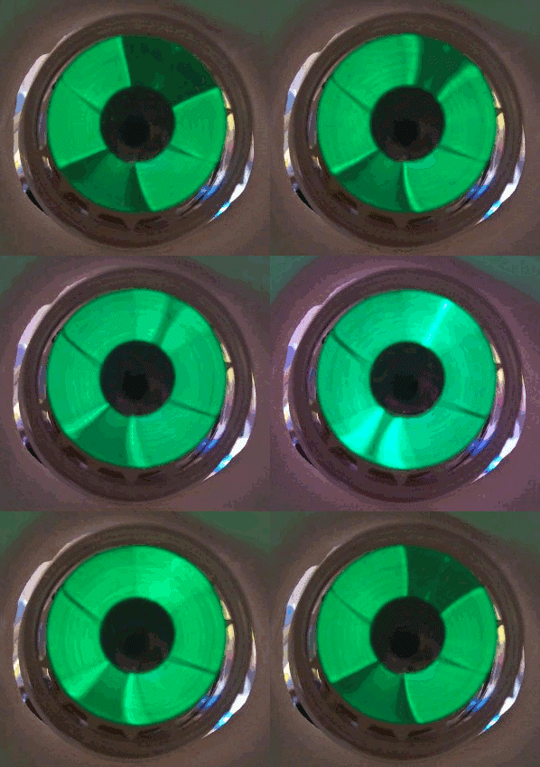
A magic eye tube or tuning indicator, in technical literature called an electron-ray indicator tube, is a vacuum tube which gives a visual indication of the amplitude of an electronic signal, such as an audio output, radio-frequency signal strength, or other functions. The mag...
lavish valley
@viscid tusk are those black things capacitors
lavish valley
How
viscid tusk
a component tester
lavish valley
I don't have one
lavish valley
Ok
 spark fiber
22kp = 22000pF = evidently 22nF
lavish valley
What a weird way to say nf
 half plover
Not really. I’ve seen 10nF represented as 10000pF
lavish valley
Well that cap above it says 5000pf
lavish valley
These are paper and wax
primal warren
Yeah, the black things are capacitors (possibly paper in oil)
viscid tusk
My DIY rigid coax stripper works great https://mobile.twitter.com/colinza/status/1292447915617792003



 old smelt
I keep watching projects like this and this that are making LoRa communicators.

It is very simple and low component count / cost device.
It called as armageddon communicator but I think it can not survive any disaster,
I making it for fun and learning communication, It is super hi tech walkie talkie,
you have much more cool smart device in you pocket wi...
It seems like one pain point is having to build a hardware keyboard.
We drag around this phone with us so what about using the phone as the input/output and having a “dumb” LoRa radio with Bluetooth connection? And then maybe the “dumb” LoRa radio could serve several phones in the local area. I’ve never done anything with LoRa so I’m curious what issues would be expected with a project like this?
As for hardware, I’m thinking a NrF52840 Feather with a LoRa Featherwing would do the trick.
These are just some notions bouncing around in my head and wondered if anyone has experience to share along these lines?
old smelt
I fully suspect that the hardware may be the easy part and the software/network stack/encryption may be the hard part.
idle oxide
@old smelt Meshtastic is something along those lines: https://www.meshtastic.org/
Meshtastic
An opensource hiking, pilot, skiing, Signal-App-extending GPS mesh communicator
Using LoRa for emergency communications / completely terrible TCP/IP networking is a component of some upcoming research for me, so I am VERY INTERESTED in these kinds of things.
primal warren
It seems like LoRa loses its appeal if you have a GSM network available, so using a phone to speak Bluetooth to a LoRa gateway isn't a widely applicable use case. However, there are Bluetooth keyboards out there, which would make such a gateway/display a more logical approach.
old smelt
Thanks for the good ideas. I agree that cell service would be best if available. I’m thinking that backup modes like Lora could be useful in emergency situations or for other remote connections.
The meshtastic seems like a lot of good reading material to start with. Thanks @idle oxide.
idle oxide
I've got two Meshtastic boards (delivered to my workplace, which I haven't been to in a while, so I haven't picked them up yet but will in the next day or so) so I am looking forward to seeing if they work.
viscid tusk
Now I just need to play some tetris to get this all in the box
viscid tusk
yay
 chrome spruce
Is that an oscilloscope?
primal warren
Looks like a spectrum analyzer to me
 hollow furnace
Is this a good place to ask for help with Nrf24L01 transceivers?
normal drift
Yes. May not be a good time (weekend) but it’s a good place!
idle oxide
Hello folks! I have a Raspberry Pi LoRa bonnet (https://www.adafruit.com/product/4074) that works swimmingly with the Python test code, but I'm wondering if there's any way to access it over /dev (I have modprobed the i2c-dev module, but i2cdetect -l just shows me i2c-1 unknown bcm2835 (i2c@7e804000) N/A and I think the bcm2835 is a Raspi chipset thing and not the actual bonnet showing up)
and/or put it into a KISS/TNC mode of operation?
if not, no big deal, can likely shoehorn the LoRa Feather M0 into a TNC, but it would be nice to do it with the bonnet as I already have it and there's a nice antenna attached.
normal drift
@idle oxide Not quite sure I understand what you are trying to do, but just in case it helps, the OLeD screen is the I2C part of the Bonnet. The LoRa module is accessed via SPI.
idle oxide
Ohhhhh huh, ok. I hadn't thought about the screen. What I'm ultimately trying to do is lay TCP/IP on top of LoRa, which is possible with at least the RFM9XW breakout (https://github.com/kc1awv/KISSLoRaTNC).
I understand that the bandwidth will be absolutely terrible, which is fine. Just trying to build a proof-of-concept.
normal drift
If it can be done via the Adafruit Breakout, I don't know why it would also not be possible with the bonnet. I think all the pins are available.
idle oxide
Problem is, the implementation is Arduino code and I am definitely not bright enough to port it to a Raspberry Pi. hm.
normal drift
ah -- that may be a challenge. the "blinka" interface on Raspberry Pi hides a lot of the details for the bonnet demo code.
idle oxide
it's ok! If I can get it to work on the M0 LoRa Feather, I'll just get another one and stick it on the Pi. I'm sure I'll have a use for the bonnet anyway.
normal drift
I worked with TNC's a long time ago -- IIRC it was at 300 baud - terrible bandwidth was a way of life 😉
idle oxide
hah! indeed. I mean... I hope it's not that bad -- https://unsigned.io/15-kilometre-ssh-link-with-rnode/ suggests that it's more like 3G or dialup -- but if I can get anything at all that will make me happy.
granite spear
As I recall, LoRa maxes out at about 20kbps for the shortest-range, least-sensitive configuration, and drops in speed from there for the longer ranges, even down into the "seconds per bit" rather then "bits per second" territory.
idle oxide
@granite spear huh, that's not what I've heard. Wow that's slow. whoof.
granite spear
Actually I'm exaggerating a little... the max-range setting seems to be about 18 bits/sec raw, probably a little less with preamble and packet overhead.
normal drift
I once worked with an underwater acoustic device that transmitted at 1 bit/sec -- it was great -- you could receive and copy the data by ear and pencil 😉
like very slow morse code...
primal warren
I vaguely recall the Voyager data rate is something like that
normal drift
Talk about LoRa .... thats really long range.....
 mortal verge
Hi all, I recently bought two of the Adafruit-sold SDRs ( https://www.adafruit.com/product/1497 ) and I simply can't get any of the FM band ( my first test for a strong signal, which I thought would be dead simple ) but all I get is noise. I'm on a Mac and I'm running CubicSDR, which as far as I can tell from John Edgar Park's video demo and others, should * just work *. But after a ton of fiddling around, I cannot get any FM radio stations to show up. Am I missing something here?

If you've ever been curious about software defined radio (SDR), this USB stick is the easiest way possible to have fun with a powerful, configurable receiver. Packed with the powerful ...
Since I bought one for a friend, I tried that one, thinking that maybe the hardware was bad, but got the same exact results. (107.3 in the Boston area should be super strong. 😦
primal warren
I would look at the antenna connection first
mortal verge
Yeah, I tried pulling the antenna to USB connection and plugging it back in on both of them, and there's literally no change in the noise level, which I found strange. I can find tiny little other signals that seem like data or devices here and there, but the fact that I can't find FM stations makes me think there's something significantly misconfigured.
primal warren
That's an odd one. Alas, I don't know how to go about debugging it.
 dark tiger
Ok, I got looking at phone repeaters
Considering the pricetag, I doubt I'll see purpose to buying one, so I thought about trying my hand at making one
The question I came to is about the pcb design
primal warren
Like POTS? 48V + ringing?
dark tiger
Well, like a mobile booster
primal warren
Ah. I got a good price on one from a marine supply store (it turns out there aren't cells out on the water, so boaters are a good market for boosters/repeaters).
 restive fjord
SKR Nomadic Research Labs
Audio and Comm Console
https://microship.com/audio-comm-consoles/
Steve has the ship to shore thing adequately covered. ;)
I think there's doo-dads you can buy that extend your cellular phone where there's no cell tower, via WiFi which you provide, and Internet.
But that sounds a lot like a cell phone that has WiFi capability. I don't remember if there's a real difference.
viscid tusk
Yeah, I tried pulling the antenna to USB connection and plugging it back in on both of them, and there's literally no change in the noise level, which I found strange. I can find tiny little other signals that seem like data or devices here and there, but the fact that I can't find FM stations makes me think there's something significantly misconfigured.
@mortal verge The antenna included isnt long enough for 2m FM band
you need a piece of wire about half a meter long
you also need a good ground for the antenna
some PCs can introduce a huge amount of noise on the USB ground if its not earth referenced
Also try play with the AGC controls to see if that helps
the mag mount antenna also benefits from being stuck to a nice piece of metal to act as a ground plane
normal drift
@mortal verge FYI -- I can receive a high power local station with mine - 97.5 here in NH
 fossil sail
I made a direct conversion HF receiver. Why can I only hear signals at around 9:30PM - 11:00PM?
granite spear
(vague handwave) Because the ionosphere mumble mumble...
primal warren
I suppose it does depend on the band, conditions, your antenna, and QRM
 worldly valve
what is the best way to boost the antenna signal on an fm radio transmitter but keep it under legal limits
fossil sail
Cut the antenna to 1/2 or 1/4 of the wavelength of the frequency you are transmitting on @worldly valve
worldly valve
how do i do that?
primal warren
Note that the antenna length won't be quite the same as the free air wavelength
fossil sail
The green thing is the antenna cut it to 1/4 of calculated measurement shown on the website
(Or extend it)
primal warren
Note that if you just straighten out the coil, you'll get more gain/range
worldly valve
the calculator takes forever
primal warren
Just divide 29980000000 by the frequency to get the wavelength in centimeters
primal warren
Yeah, seems right
worldly valve
thats long
fossil sail
make sure it is 1/4 of 78cm
or 1/2
Lol u think 78cm antenna is long.You should see my 66ft antenna lol
primal warren
It's 1/4 of 313cm, which is 78cm (which should be further adjusted, but that's in the nature of fine tuning)
Just straightening out the antenna coil will give much better signal
fossil sail
Ah ok
fossil sail
My 66ft is for HF RX
normal drift
80M quarter wave?
normal drift
only if you ask a question 😉
 tranquil pelican
ok, wait lemme translate it for u 😄
Ok, i am retuning my old radio from 1986. Now, i have a problem. Currently, range of the radio is ~92-108MHz. I still want to go lower to 88MHz. I can't do it, because it is changed by inserting core of the coil. I unscrewed core all the way down, but i need to go lower.
Now, what to do?
unscrewed this core
i can give you schematics
normal drift
Not something I can help with, sorry -- hopefully someone else can and will as soon as they are available. Good luck!
tranquil pelican
ok, thanks
or wait
when you remove core from the coil, then inductance will be lower?
@normal drift
normal drift
Sorry -- I don't know much about this type of issue. There are others who are often monitoring this channel that should be able to help. It may take take awhile until they respond.
primal warren
That does seem backwards, lower frequency is normally higher inductance (which would be the coil engaging with the core more, not less)
tranquil pelican
so what you actally mean?
primal warren
I mean the core should be centered in the coil for lowest frequency operation.
tranquil pelican
hmm
i think that my lower frequency range was going up when inserwing the core, but i can check it
wait a minute
nope, it works the opposite way
primal warren
Either the coil enclosure is different than you think, or you're tuning a local oscillator?
primal warren
If you're going to do things like re-tune radios, you should probably do some learning on how radios work, or you could end up more confused.
tranquil pelican
hmm
i prefer repairing polish amplifiers from 80s, but it's my own radio and i want it to work on new fm range
and i can't really understand some words that you use :c
primal warren
Alas, I do not know the Polish term for "local oscillator", "mixer", and other radio sections
tranquil pelican
if removing core makes good effect for me, then what about making gaps between turns on the coil?
primal warren
Making gaps will tend to lower the inductance, which would change in the same direction as removing the core
tranquil pelican
ok, then i will try to make some gaps
worldly valve
just wondering is there a way to tell how far my radio will go?
primal warren
If you run out of range by changing inductance, you can get even more range by changing capacitance. You'll eventually cause the circuit to not work as well, but I do not know what that point would be.
tranquil pelican
ok
i will make some gaps and try to retune it
then i will write how the result is
primal warren
@worldly valve Try it and see is probably your best bet.
worldly valve
ok
so just take my radio for a walk i guess and see how far my transmitter reaches
primal warren
I did that with one of my LoRa radios and a simple 18cm wire antenna. It continued to work up to a range of 1100 meters (1.1km).
worldly valve
dang
granite spear
Generally, no, except for very low frequencies. It's a problem for submarines.
half plover
That’s what my senior design team is looking at solving 😉
We have SBIR funding from NASA which is pretty cool
granite spear
What kind of approach are you pursuing?
 warm tapir
Visible Light
@half plover What kind of range is possible with that?
half plover
There is a lot of variables that control that. In surface waters, maybe 2-3m. As you get deeper, maybe up to 25-30m where turbidity is lower
granite spear
Cool. I previously worked on long-distance laser comms, though in air rather than water.
restive fjord
granite spear

WIRED
The laser was shot from a balloon 20 miles above the Nevada desert. Its target was a one-and-a-half-inch hole on another balloon. Val Kilmer never had it better.
half plover
Yeah, lots of people doing it with lasers
Fiber internet is technically VLC
We are building a low cost system with LEDs. Much harder lol
Also, fun fact: LEDs can be used as photo diodes 😉
granite spear
Yep, that's a handy trick sometimes.
primal warren
They can be fairly high speed photodetectors
half plover
That too
normal drift
@vocal veldt You might be ionterested in this https://forums.adafruit.com/viewtopic.php?f=60&t=168167&p=825925#p825925 We now have working versions of rfm9x/rfm69 for MicroPython...woohoo!
worldly valve
im gonna try to develop some software for radio. wish me luck
 vocal veldt
@normal drift Are they open to adding their changes to a github repo?
Pretty neat that the _circuitpython_TinyLoRa and RFM9x/RFM69 libs now BOTH have ports for micropython targets
normal drift
@vocal veldt you mean a new repo for a MicroPython version?
Is there one for tinylora?
Would you post to the forum discussion and ask if the person who ported it wants to do that? Or if they don’t , is it ok if some else does.
vocal veldt
@normal drift ya - https://github.com/fantasticdonkey/uLoRa

GitHub
LoRa / LoRaWAN + TTN for MicroPython (ESP32). Contribute to fantasticdonkey/uLoRa development by creating an account on GitHub.
normal drift
ah -- nice -- Do you want to follow-up in the forum post to encourage the original poster to put it on github if they want to maintain and expand it?
It still needs some work. I'm not sure of their intent for the long term but once it is up, I can fork it and do some things I'd like to ry with it.
vocal veldt
@normal drift I'll read the post tomorrow, I usually do sweeps on fridays
I'll give them some encouragement to hopeflly post up on github instead of the forums
normal drift
They posted it to the forum at my request originally and I modified it and posted it back for them
vocal veldt
worldly valve
what is the best free broadcast software? i have tried some, but i cant find one i like. i want one where it will randomly play my tracks
primal warren
I just use iTunes.
 cloud yoke
VLC plays mp3s
 winged kiln
@normal drift So we need to transmit a panoramic picture, data from a gps, and from a gyroscope. I haven’t picked a camera yet so I can’t give a specific number, but reading off google around 8mb? I think my best bet is to just use a JPEG and reduce the quality significantly? What do you guys think? Again I have to be able to send this 1.5miles at max, in the worst situation. Is there a way I can calculate which frequency would be best for me? I don’t need the picture to get their fast as well. A VTX for FPV drone flying goes at 5.8GHz, but their image quality sucks at long range and won’t be as big as a panoramic.
winged kiln
Ok so update, I have started looking into using a GSM module with a rasberry pi or something that will allow us to connect a sim card and use that to send a photo to ourselves, by uploading the picture to a drive or maybe sending it to another phone on us. We will be at a launch site and I am not educated on how SIM cards work, but don't SIM cards need to have a cell tower nearby? I was also wondering about how the communication works? Does a SIM card change the frequency it sends on? Is that what 4G 3G and LTE stand for?
restive fjord
You have to be near a cellular tower for GSM.
They faked Star Trek by planting repeater towers nearby.
Since the tower is so close, your own radiated signal can be very weak.
winged kiln
Thanks Nis! I am so glad I joined this discord. You guys are full of knowledge!
So a Sim card/GSM module is able to change the frequency it send data on correct?
restive fjord
Do you own land on both ends of the proposed radio link?
winged kiln
No, we are just a college team and reserving a launch site nearby
restive fjord
There were two primary cell net compatibilities. One is GSM.
CDMA is the other one.
Really new phones can do both.
But you can't switch over on a convenience basis.
You still commit to a given system.
I would guess that any cellphone based solution would have acceptable bandwidth.
The exact locale matters some.
If you had all the money 💰 in the world you would use every available service and see which one delivers the best value.
Then discontinue the others.
Physically it probably comes down to less than three networks to choose from.
Around here that means AT&T or Sprint.
The others are reselling those two, in my town.
I have Ting, which resells Sprint.
 paper dune
Any one here know how to decode the bluetooth characteristic specs? I'm having some issues working with the Fitness Machine Service
 coarse crater
Hey I ve started working on GSM can anyone pls share best wiki links or books regarding that
 dark nymph
Any one here know how to decode the bluetooth characteristic specs? I'm having some issues working with the Fitness Machine Service
@paper dune Can you tell us more about the issue you're encountering and show us your code ?
Hey I ve started working on GSM can anyone pls share best wiki links or books regarding that
@coarse crater What are you building with GSM and what kind of information do you need to get going ?
 unborn scroll
Hi! I got a couple of the lora radio bonnets for Raspberry Pi. And I am going through the setup in:
https://learn.adafruit.com/lora-and-lorawan-radio-for-raspberry-pi/usage
And all works except that the The Things Network site considers my device as never seen... is there any trick I should know to see my device data populate in TTN website? I am in nyc, which appears to have a gateway according to the map in their website.

Adafruit Learning System
Add low-power long-range radio communication to your Raspberry Pi Project
 broken hinge
I am working on a project on the nRF52840 and am at the point where I need to start work on the wireless part of the firmware. However I am somewhat confused on terms and would like some grounding:
It is increasingly looking like "Bluetooth Low Energy 5" / BLE5 is commonly used to refer to Bluetooth 5 in general - not just a subset or mode like Bluetooth Mesh? And as such, I should stop going around the Nordic Semi APIs and examples for BLE in search of the same for "bluetooth proper"?
granite spear
So, the Nordic chips only support BLE, rather than "classic" Bluetooth like paired headphones. And indeed, BLE5 usually refers to the whole spec, not just the mesh features.
If you need classic Bluetooth too, you want to look for a "dual mode" chipset.
broken hinge
Excellent. I'll disregard "BLE" as marketing lingo and just read "Bluetooth 5" when I encounter it in docs and API 🙂
paper dune
@dark nymph So the issue is that I'm trying to decode the data that I receive while trying to use this service but all I get are single string characters when I'm expecting integers, I'm kind of out of my element here decoding bit and bytes
granite spear
@paper dune Can you give some more info? It could be that you're getting a character which is simply supposed to be interpreted as a numerical byte. Or maybe you're getting part of a multi-byte integer which has to be decoded. Hard to tell offhand.
dark nymph
@paper dune I have not run this in a very long time, but I bet I was trying to do the same thing you are. This also might be some sample code from Adafruit's learn guide too and not my own. I forget 😉
At the time, I just wanted to scan and print all the things I saw. BUT if you let this run it will likely crash. I just ran this on a CP Playground Bluefruit Express and it ran fine for a short time and then crashed
<Address b4:fb:e4:8f:a8:f4> <Advertisement  >
Traceback (most recent call last):
  File "code.py", line 30, in <module>
TypeError: can't convert bytes to int
Hopefully that helps you some if only in shared misery. Maybe someone else on the channel can offer more specific help if you share your code as well.
paper dune
yeah so my issue is more about decoding, I can get "data" it's just gibberish since it's not being decoded/interpreted correctly. This is the callback to a function that I have a toy app https://github.com/alexdmejias/web-cadence-indicator/blob/master/src/App.js#L102-L117. The spec for the characteristic lives here https://www.bluetooth.com/specifications/gatt/services/ (sorry it's a pdf download and what I'm interested in starts at pg. 42) but you can also find the spec as xml for the desired characteristic here https://www.bluetooth.com/wp-content/uploads/Sitecore-Media-Library/Gatt/Xml/Characteristics/org.bluetooth.characteristic.indoor_bike_data.xml . I have a data point that's something like "4402FE014600050000"(hex), I'm just not sure how to decode it to something useful
Bluetooth® Technology Website
GATT Services are collections of characteristics and relationships to other services that encapsulate the behavior of part of a device. All Service Assigned Numbers values on this page are normative.

GitHub
Contribute to alexdmejias/web-cadence-indicator development by creating an account on GitHub.
granite spear
Is that an actual hex example or just random characters? I would normally expect to understand this format, but the example doesn't parse like I would have thought, so I'm hesitant to give you advice that doesn't work.
paper dune
err trying to post another value but the bot keeps blocking it
0b 01000100 00000010 01001110 00000010 01001010 00000000 00000101 00000000 00000000
I guess the bot doesn't like one unbroken string
The values are kind of weird because they mix the amount of bits depending on the piece of data that you are looking for, sometimes they use 8-bit sometimes 16 or 32
granite spear
Yeah, that doesn't quite make sense to me either. I'd need to read the spec more carefully, as I assume there are some padding rules which aren't specified in the XML.
dark nymph
@paper dune I wonder if there is a ReactJS Library to help you you with Bluetooth. I don't work with ReactJS but a quick search and this one popped up https://www.npmjs.com/package/react-bluetooth
 paper dune
@dark nymph I took a look at that library and a few other but it seems like they are all just helpers to get the raw data and assume that you can figure out how to decode the data yourself
@granite spear yeah the xml spec assumes that you already know how to deal with raw ble data
thank you both for the help
dark nymph
What are you reading data from?
And does it have a published spec of its data structure?
paper dune
it's from an indoor bike, complete spec live in this pdf and the barebones data structure is here https://www.bluetooth.com/wp-content/uploads/Sitecore-Media-Library/Gatt/Xml/Characteristics/org.bluetooth.characteristic.indoor_bike_data.xml
trying to get an actual link to the spec and not some suspicious pdf file
dark nymph
Lol
paper dune
this should work if anyone is interested https://www.bluetooth.org/DocMan/handlers/DownloadDoc.ashx?doc_id=423422
dark nymph
And if you connect to it with a raw Bluetooth app like NRF connect it works fine?
Reason I ask, is because not all indoor bikes will implement that Bluetooth spec properly.
paper dune
yup, I just pulled some data again
inst speed  8.5km/h
inst. cadence 45.0 per min
inst power 8W
Heart rate 0 bpm

44 02 52 03 5A 00 08 00 00
OK that’s a good sign.
paper dune
directly from nrf connect
dark nymph
You still have the same problem. But at least you know the bike is transmitting the data properly. And it very well could have not been.
This is an interestingly similar question https://stackoverflow.com/questions/49503063/how-to-get-bluetooth-le-characteristic-value-from-packed-byte-array

Stack Overflow
Using the examples in the Noble-Master Node package, I've got as far as finding the top-level characteristic I need from the TacX Vortex Bluetooth Le bike trainer I'm using. However, I cannot figur...
paper dune
Per the above link and looking at the spec, it looks like the first piece of data is uint16 flag field, I'm not sure why I'm getting 2s and the fields enabled don't seem to match the data that I have
 const flags = data.getUint16(0);

    console.table([
    flags & 0x0,
    flags & 0x1,
    flags & 0x2,
    flags & 0x3,
    flags & 0x4,
    flags & 0x5,
    flags & 0x6,
    flags & 0x7,
    flags & 0x8,
    flags & 0x9,
    flags & 0x10,
    flags & 0x11,
    flags & 0x12,
    flags & 0x13,
    flags & 0x14,
    flags & 0x15,
    flags & 0x16,
    ])
You want flags & (1 << n). Right now your masks are the numbers, not the particular bit.
(And also you're using decimal numbers with a hex prefix.)
paper dune
I'm not entirely sure what you mean by the last comment
would n be decimal numbers in this case? as in:
    console.table([
      flags & (1 << 0),
      flags & (1 << 1),
      flags & (1 << 2),
      flags & (1 << 3),
      flags & (1 << 4),
      flags & (1 << 5),
      flags & (1 << 6),
Yes, that's correct.
The last comment is saying that 0x16 is actually the number 22, whereas I assume you meant 16.
paper dune
oh I see, bitwise operations still baffle me, so would an output like this make more sense? it still doesn't make sense to me if the spec says that the first piece of data is 16 bits where each bit indicates the presence of different features
granite spear
That's saying that there should be 3 fields present, the first of which is the average speed, from the flag bit in the second bit position. However, I don't understand the following bytes, since they don't match the documented widths of those 3 fields. I expect there are some extra padding rules affecting that, where a uint8 is actually stored as two bytes, etc.
paper dune
@granite spear @dark nymph I called it quits and asked in stackoverflow, someone has kind enough to provide literally everything I needed https://stackoverflow.com/a/64004591/2332633, dropping this here in case anyone else has the same question
Stack Overflow
I'm trying to use the Fitness Machine Service + the Indoor Bike Data characteristic to get the cadence data. By using the nRF Connect Android App I can see that the data is there, sample data:
inst.
Now I just have to do it in circuitpython
granite spear
Ah, great. The "instantaneous speed is always present" part was the missing piece of info for why things didn't line up before.
paper dune
yup, I meant to confirm that in the spec but I forgot about until you just mentioned that
dark nymph
That’s not cheating. That’s working smarter. 👍
slender current
@paper dune I can help with ble if you have trouble
 spiral tapir
Can anyone give me insight on what i might be doing wrong here?
I'm using this bonnet on a raspberry pi zero w: https://www.adafruit.com/product/4073 and following the guide from the learn section: https://learn.adafruit.com/adafruit-radio-bonnets/sending-data-with-the-rfm69
I've done all the setup steps, verified spi and i2c, and oled screen is working properly. However, I can't seem to get the bonnet to receive packets from my 433mhz remote. Here is a direct link to script I'm using https://github.com/adafruit/Adafruit_Learning_System_Guides/blob/master/pi_radio/radio_rfm69.py (which is also in the guide linked above). The only thing I've changed here is line 53 to be rfm69.encryption_key = None and line 49 to be rfm69 = adafruit_rfm69.RFM69(spi, CS, RESET, 433.0) to match the remote.
primal warren
I suspect that remote works differently and will need a modified setup.
spiral tapir
It's just a simple etekcity remote for rf outlets. There are a bunch of tutorials of people making raspberry pi controlled setups with them. I just don't get why the bonnet doesn't see anything on receive. It's simply a 433mhz packet to read I believe?
primal warren
It's probably just an ASK/OOK modulated stream, non-packetized.
restive fjord
is it possible to disable retransmissions and ACKs using the radiohead library?
the protocol I'm creating deals with those already, so I don't want to waste airtime on something that's already being done
I'd like to keep error correction though, so kind of like UDP, where every datagram is uncorrupted, but there's no guarantee it will be received
normal drift
@restive fjord use "Datagram" - not "Reliable Datagram"
restive fjord
how so?
normal drift
just a second
restive fjord
thank you
normal drift
use the RHDatagram mode https://www.airspayce.com/mikem/arduino/RadioHead/classRHDatagram.html
instead of RHReliableDatagram https://www.airspayce.com/mikem/arduino/RadioHead/classRHReliableDatagram.html
restive fjord
alright, thank you
normal drift
Good luck -- BTW -- I think the max payload size may be 292 -- trying to confirm.
restive fjord
pretty sure the max packet size defined in the header was 255 bytes
normal drift
Looks like that is correct -- no sure where I got the 292 from. I never press it that hard 😉 you may have to leave room for the CRC
@restive fjord Sorry, I was confused --- in the CircuitPyth0n library it is limited to 252 to allow room for the header.
granite spear
Sure, that's close enough.
granite spear
Yeah, ultrasound at that range with a target as small as bird is probably going to be need to be dangerously loud.
Radar is probably at least possible, but not easy, since birds are small and they aren't made of metal. The data you get out of a radar system is also confusing to interpret, as the simplest systems just give you a distance and velocity but not actually a direction or height.
One step up from that would be something like TI's millimeter-wave radar chips, which give some angular information: https://www.ti.com/sensors/mmwave-radar/overview.html They have some demo videos on Youtube which show what kind of data you can get from them.
TI delivers a broad portfolio of mmWave sensors to meet automotive and industrial market needs.
half plover
You could definitely build one yourself
But it would be a huge undertaking
I’d suggest working with the TI sensor and get a feel for how it works and then build your own piece by piece
Also watch some videos on EMI propagation and RF design and antenna design
restive fjord
There's a lot of digital-interface two-way radios on the market.
The days of analog front panel controls (potentiometers and encoders that are rotary switches with complex bit patterns generated) are just about over.
Now you have LCD or outright TFT displays.
They are very (very) small form factors.
Like a shortwave portable.
Continued in an uploaded .TXT file; original deleted here in channel.
http://3dprinterpartsandaccessories.com/dad/old-amps/
Now that's an amplifier!
I heard him this morning on 160 meters, CW, bottom of the band. Delaware, to Connecticut (where I am).
restive fjord
The FCC is doing enforcement on RFI from LED signs. ;)
Two-way radio ops routinely complain of radio noise at traffic lights around here. ;)
primal warren
A lot of LED lighting also produces copious RFI
restive fjord
I did a 7-segment display with an array of light-emitting diodes. Really very noisy, radio-wise.
primal warren
I've been known to switch LEDs (and gas discharge lamps) with opto-isolators merely for the risetime slowing, to reduce RFI generation.
restive fjord
aha. nice.
restive fjord
I'm trying to figure out if I need a > 28 MHz oscilloscope to look at AM mode modulation on 28 MHz ham band transmitter.
I don't see a good inexpensive path around that requirement (a scope bandwidth in excess of the signal carrier's frequency).
We're really talking about 27 MHz fwiw. ;)
primal warren
I don't think you do, if it's an analogue 'scope: they still respond to (and past) their bandwidth rating, just with less sensitivity, so the voltage calibration isn't accurate, but for relative things (like modulation measurement) they work fine.
You'll also get waveshape distortion for non-sinusoidal waves, but an AM carrier is generally either sinusoidal or (in the case of class C amplifiers) can be regarded as such.
half plover
There's some kind of downsampler you can use to measure high RF waveforms
I saw it used in a video of a guy making a super fast oscillator of like 28GHz or something like that
primal warren
I did use an equivalent time sampler to characterize a fast risetime (~350ps) pulser a while back. However, for modulation, you don't need anything that fancy, you can simply build an AM detector (known as a "demodulator probe" back in the day) to look at the envelope with even a 100kHz 'scope.
half plover
oh gotcha
restive fjord
Yeah I just want to dial down the power of the transmitter and adjust modulation on AM so it's clean.
These transmitters ship too hot, for people who want to radiate strong signals. I want it for QRP (very low power).
What I do now is just watch the S-meter on a receiver, and dial back the AM modulation so that the needle moves less during speech.
And also listen on the receiver for the worst distortion.
I'm probably at about 65 percent modulation.
50 is proper; the CB'ers these radios were made for want 100 percent or more. ;)
(though I'm sure the factory setting is under 95 percent) (and fairly clean)
primal warren
Heh, I've got an old vacuum tube modulation monitor that would probably do the job
restive fjord
Yeah exactly .. that's the kind of thing I need to have on-hand.
The easiest way to adjust modulation is to ask a skilled listener a few miles away to judge your audio when three or more other stations are also present (all with good audio).
If your signal is the quiet one in the group, then you know to adjust it upwards slightly.
primal warren
I'd aver that the easiest way is a modulation monitor. Seeing the pattern on the screen makes it quick and easy to dial in exactly what you want.
restive fjord
I have no idea where those are sold and what they cost. ;)
Heathkit sold a 'station monitor' that was a kind of oscilloscope. Years back.
primal warren
Got mine at a hamfest for $5, but an ordinary oscilloscope and a little circuitry will do the trick.
restive fjord
I have a 25 MHz digi scope (Owon).
primal warren
That would probably be sufficient, but it probably doesn't have a ramp output like an old-style 'scope, so you'd have to gin up something (not too tough), and a demodulator (a few discrete parts)
If you have a signal generator that can produce a ramp/triangle, that would work.
restive fjord
At audio? I think I have a LabVolt that'll do that.
square wave and sine wave
no sawtooth
I used to have a function generator, but gave it away.
primal warren
Frequency doesn't matter, audio range is fine. A sine wave might do, depending on how well behaved your scope is
Or you could integrate your square wave with an op amp and capacitor
restive fjord
Well the Owon is rated to 25 MHz and the radiated signal can go pretty low, to about 25.1 MHz.
primal warren
With the demodulator, you'd only need about 10x your ramp frequency, so 25MHz is way more than sufficient
restive fjord
25.7 MHz.
Really.
So I build some kind of detector, and that takes the 25.7 MHz out of the equasion.
primal warren
Right. You're just examining the modulation envelope, which is at your modulation frequency. 1kHz is probably fine.
primal warren
To really get the shape, the scope should be at least 10x that, so a 10kHz scope is plenty.
restive fjord
Oh okay I'm getting you.
A full oscope picture is populated by the RF carrier 'filling' the envelope, but that's superfluous.
primal warren
Right, the old modulation monitors just sent the signal to the deflection plates and called it a day. Worked fine if your transmitter could drive such a capacitive load.
restive fjord
It's the envelope shape and amplitude and crossover points that matter, not the 'filled in' RF (which you cannot make out, the individual cycles, anyway).
and the 'detector' (two 1N914's) guarantees my audio has 'passed through the transmitter, entirely, from microphone to antenna' so that I'm looking at the real world, not the input.
primal warren
Yup. I'll generally use a 1N34A (or a 6AL5), but 1N914 works too
restive fjord
the youtube scope guy covered most of this, but they plod on and on until you change the channel, if you're not invested in the minutae. ;)
primal warren
Most youtube presentations are not paced well for me 😕
restive fjord
Especially if they're struggling with their English, when they aren't native speakers.
primal warren
That, and my hearing issues, makes for a frustrating combination
restive fjord
Like someone who says 'um' about as often as a human blinks their eyes.
Well you just managed to pull out of me understanding I already had but didn't own. ;)
like a leased car
See that's why we played with the oscope in the lab in high school.
lissajous figures were my favorite thing to do with them.
primal warren
I'd modify old junk TVs into Lissajous viewers and gift them to my friends to watch while listening to music.
restive fjord
So this has all got to be germaine to audio amplifier fine-tuning adjustments as well.
For home audio (nothing to do with radio) and class AB amps and all that jazz.
The point is clean waveforms so there's less noise and distortion and unwanted .. heating of parts, perhaps.
On radio it's a lot about not radiating unwanted harmonics.
Low audio is safe, but not effective (it annoys others on the air to have to struggle to hear what you're saying)
primal warren
A lot of the sonic character of class AB audio amplifiers comes from their crossover behavior. Many people try to tune them up at full output, where crossover behavior is masked: you'll get the best results running them at low level, where crossover distortion dominates. Once that's dialed in, it will generally sound as good as it can.
Note: this is for high-fi: guitar amps are used (and adjusted) in different conditions for different characteristics.
restive fjord
Sure, yeah.
We had enough of this theory in high school so that it's not at all foreign.
But not nearly enough hands-on labs.
primal warren
There are some great labs in "Learning the Art of Electronics", showing how an ordinary 2-transistor push-pull amplifier has crossover distortion, and ways to combat it using bias, predistortion (including it in the feedback loop of an op-amp), etc.
restive fjord
;) predistortion i love that idea ;) /english
sounds like a current political platform
primal warren
The diagrams explaining it are great: they show a dog in the loop and refer to making an "inverse dog" to undo whatever is happening, or create a specific waveform
primal warren
I'm really liking the book, I wish I had bought it years ago
restive fjord
Max Creek (a band) used to do the Grateful Dead method of stage mic's - two mic elements 180 out of phase, aimed pretty much at the loudspeakers behind the musicians.
primal warren
We used to use cardioid pattern mics in a similar way, aiming their nulls at noise sources
restive fjord
Yeah the sound guys in the band would put pink noise through the loudspeakers and adjust a graphical EQ for room acoustics, a few hours before the band went on (with an audience).
I need to get that book.
For years I depended on ARRL pubs like Radio Amateur's Handbook.
primal warren
The ARRL books are a good source of information, even the older ones that can often be had cheaply
restive fjord
I tried to give away almost all my equipment. I was done. Then, I wasn't. Now I think I have more than I had, then. ;)
primal warren
I have some understanding of that
restive fjord
lol
I keep seven bicycles inside the apartment, which is a sign I'm incorrigible anyway you slice it.
(I ride every one of them)
primal warren
And here I am incorriging you 😉
restive fjord
;)
This time it's different; I'm fighting a lot harder to tolerate the clutter.
Too many things given away I now wish I had.
primal warren
I did deploy some insulated Copperweld as an antenna recently, but haven't hooked a transceiver to it yet.
You're in easy HF range
restive fjord
Well there's some very nice designs based on heat sinks.
Yeah I don't have the lower bands; just 10m at the moment.
I used to work 40m and 20m out of this apartment, and some 12 meters stuff when the sunspots were good for propagation.
Also there's been unbelievably strong hash on the lower bands, lately.
primal warren
A bit far for 10m, it would take a bit of luck (or better antennæ)
restive fjord
I heard just one CW station on 160 meters this morning .. from Delaware.
primal warren
I wonder if I have the coils for 160m
restive fjord
With the upstairs neighbor home 24/7/365 it's hard to .. manage explorations required .. to track down RFI stuff on-premises.
primal warren
I have the advantage that I'm neighborless and surrounded by farmland
restive fjord
That's great! That's the way to live.
The CW station I heard was right at the bottom of the band, maybe 3-5 kHz from the band edge.
Quite a bit of fading, but at times he was moving the S-meter needle pretty good.
(a good 2+ S-units)
primal warren
I could, of course, hook up an actual transceiver instead of trying the building block radio pictured
primal warren
Fancy! I have the older TS-530.
restive fjord
Yeah mine was TS-520 I think.
A little soft on 15m and 10m but a good rig.
(6146-B's iirc)
primal warren
The TS-530 is kind of drifty, but performs well. I'm trying to decide whether to modify its built-in VFO (there are well known improvements that can be made), or just use an external one.
restive fjord
Yeah it was drifty for sure.
primal warren
Same 6146-B finals.
restive fjord
I have their R-599A with the extra CB band in the bandswitch.
primal warren
Amusing choice of model number.
restive fjord
oh yeah heh.
it was also branded something else.
allied maybe
I never did get the matching transmitter.
That's what I should shoot for.
The Drake radios were nice.
We had a Johnson Viking transmitter, and a National NC-300, I think, on the receive side, for a club station (1974).
That National I liked a lot.
I have to get going, here. Thanks for the modulation remarks ..that's going to be great, if I can motivate to build that stuff!
By the time I have it built I should know how to use it. ;)
 coarse urchin
Hi!
I would like to know if the GPS cable(https://www.adafruit.com/product/960) can be shortened, is there a tutorial for it?
Thank you
restive fjord
If it's a tuned length, then no. If not, may devolve to soldering skills (or use of a crimped connector.
@coarse urchin
It's very early in USA (7:12 a.m.) so later in the day there may be a better response. ;)
Just guessing about the GPS cable.
coarse urchin
Thanks, I'll wait for more opinions = D
restive fjord
;)
primal warren
@coarse urchin Yes, that's an active antenna, so you could shorten the cable if you like. However, since it's an active antenna, there's not really a need to do so.
coarse urchin
@primal warren I understand you, I do it because of the container where it is located is very fair in size ,,,
What would be better to cut it on the SMA side and re-solder it? I don't know if I need any special tools ,,, or on the contrary, would I have to open the box where the antenna goes and shorten on that side?
Thank you
primal warren
I'm unaware of what the antenna internals look like. If it's easy to open the antenna enclosure and unsolder the cable, that's probably the simplest way. If it's not (for example, if it is potted), then it is probably easier to cut the connector off and attach a new one. There are various style SMA connectors available, some are crimped, some are soldered.
coarse urchin
Thanks, I'll try !!!!!
restive fjord
Good morning from California! 🙂 I am interested in the LoRa gateway and I'm curious if it's specific to the Pi3, or if a Pi4 can be used. I don't need the enclosure and prefer the $50 cheaper one here: https://www.adafruit.com/product/4284

If you're building a Raspberry Pi project and need to send data back-and-forth, the WiFi module built into newer Pi's should be fine for most cases.However, WiFi does not have a long ...
LMK if this should be posted in the pi channel
vocal veldt
@restive fjord I think you can use it with the Pi4 - I may have configured the sample gateway with the Pi4 at the time..But I don't remember.
You may want to ask RAK's technical department, there is a contact listed on the user manual for the Pilot Gateway Pro RAK7243
restive fjord
Can Circuit Playground (model 3333) or Bluefruit (model 4333) communicate with another one over LoRa?
primal warren
Not by themselves, but you might be able to add a LoRa board somehow.
restive fjord
That’s what I’d like to find out how to. I have some LoRa radios, but don’t know wiring.
primal warren
Many of them are based on the same HopeRF chips
 modern pasture
Hello. I'm currently working on a Raspberry Pi IoT project which involves imitating my ceiling fan remote. However, the remote uses 302.5 MHz to communicate with the fan and I have been unsuccessful so far in finding a module for that frequency. I was wondering if there are any radio modules out there for 302.5 MHz or if there is another solution that I haven't come across yet. Whatever the case, I look forward to a response! Thank you!
Also, here's the FCC ID.io page for the remote: https://fccid.io/IN2TX01

FCC ID
FCC ID application submitted by Hunter Fan Company for Remote Control Transmitter for FCC ID IN2TX01 ( IN2 TX01 ) User Manual, Frequency, Reports, Images and more.
granite spear
There are tunable transmitters that would work at that frequency, but unless you have some knowledge about what sort of modulation scheme it uses, that might not help much.
modern pasture
I opened up the remote the other day and was able to find some documentation on the one IC inside
I remember seeing something about modulation in there
I'll keep investigating modulation schemes then, thank you so much!
primal warren
Many remotes use something known as a "SAW filter" as a tuning element in their oscillator. You should be able to find a 302.5MHz SAW filter, at which point building a transmitter consists of rolling your own oscillator, or modifying an existing one (432MHz ones are common) by swapping the filter and tweaking the tuning a little, possibly as simply as spreading the turns of a coil out a little. On the one hand, it's not very complicated, on the other hand, some fancy test equipment and RF experience would probably be necessary.
There are probably 302.5MHz transmitters out there somewhere, perhaps modifying one of them to be controlled by your Pi would be simpler.
 edgy shale
Anyone have experience with rfm9x on a pocketbeagle?
I'm trying to use adafruit_rfm9x using adafruit_blinka
specifically getting this error, although we're prettyc onfident in our wiring
primal warren
I'd add a debug printout to see what version it is getting. If it's completely bogus (like 00 or ff), it probably is wiring. If it's something else, you may have an RFM69 module instead of an RFM9X.
edgy shale
Looks like we're getting out ff as the version. Will reexamine the wiring
fossil sail
Does anyone have tips on receiving GOES satellite?
primal warren
For satellites in general, I'm fond of a cubical quad antenna (light, easy to build, good gain), and keeping track of doppler shift. However, for GOES in particular, I don't know.
fossil sail
The frequency is 1694.1MHz so I bought a 1 meter long dish. I can clearly see the signal. But when I try to decode it the error rate is too high. Im getting about -20dbm
primal warren
A dish has a pretty narrow beamwidth, so if you can track the satellite accurately, it should give you a solid signal (although a feedhorn mounted preamp might help too).
primal warren
Ah, that does simplify things. So you have a solid signal but decoding is failing. What sort of modulation is it? I'm wondering if atmospheric variations are causing phase shifts or something.
primal warren
Ah, that would be susceptible to phase shifts.
fossil sail
I might just try getting the dish higher up
If that does not work I might have to get a second LNA
primal warren
Those are both worthwhile things to try. If there were a way to analyze what was going on in the decoding process, that might yield some useful clues.
 vapid island
I'm not sure if this is the channel to ask this in, but I have no experience, and I'm curious about trying something
some sort of paint, or something ultralight
that is passive
that could be picked up at reasonable distance (mid upper 10s of meters) by a "radar" of sorts
basically, sending up some decently large model rockets, so not a lot of room, and no power to play with
got a drone with some payload weight, and decent battery
want to make something that would allow the drone to track the rocket once it hits the ground.
granite spear
You might consider retroreflective paint / stickers. Have a searchlight on the drone and pick up the rocket position in a camera.
On the more sophisticated end, there is "harmonic radar", where you have a passive tag that reradiates a radar pulse on a different frequency, which makes it much easier to pick up and isolate from all the other same-frequency reflections.
primal warren
A radar retroreflector is pretty easy to make, just a half cube of something like aluminized mylar. You could support it with something like soda straws, it would only weigh a few grams. Making it ærodynamic might take a little creativity, however.
 waxen hornet
Does anyone know if this Lora chip can be used without/ independently of an Arduino: https://learn.adafruit.com/adafruit-rfm69hcw-and-rfm96-rfm95-rfm98-lora-packet-padio-breakouts/arduino-wiring ? Thanks

Adafruit Learning System
Radio transceiver modules for long distance data communication
normal drift
You need a microcontroller of some sort to use it.
It is not a microcontroller. itself. Just a radio.
waxen hornet
Ok, thanks
 wise quarry
anyone know of a BLE example in CP that passes a json string over UART? (or some other method, as I need to pass ~5 parameters from the BT app and store them as variables to be used later). For now, with the basic examples I can send a byte or string like echo, but not a json string like { "name":"John", "age":30, "car":null }
 flat jewel
Hi. I'm starting the design of a gaming device with wireless buttons. The controller has a matrix display and the buttons could connect with the controller at distances around 10 meters. What devices do you recomend for communications? Can the ESP8266 use a protocol similar to ZigBee?
worldly valve
can i calculate how far my fm radio will broadcast?
primal warren
You can, but you'd need to know the transmit power, the receive sensitivity, the antenna gains (and alignment, and polarization), matching network and cable losses, and path loss.
 wanton sun
I am currently making an ESP32-Pico-D4 feather. I’m having trouble with the antenna circuit. It seems like inductance and capacitors’ value changes, and I don’t know these values for the antenna I’m using.
Please help me
This is the antenna I’m using https://lcsc.com/product-detail/Antennas_Rainsun-microwave-Tech-AN9520-245_C99665.html
Rainsun microwave Tech Rainsun microwave Tech AN9520-245 US$0.35 LCSC electronic components online RF & Radio Antennas leaded datasheet+inventory and pricing
Ping me if you answer
primal warren
@wanton sun I'm not sure what you mean by the inductance and capacitance changes? Are you trying to design a circuit, and the equations fail to converge, or have you assembled something and you're examining it on a network analyzer and the readings aren't stable, or what?
wanton sun
I mean, that I am designing a circuit, and I have no idea about capacitors and inductors for RF matching
primal warren
I saw the discussion got moved to #help-with-hw-design
 torn jewel
On the more sophisticated end, there is "harmonic radar", where you have a passive tag that reradiates a radar pulse on a different frequency, which makes it much easier to pick up and isolate from all the other same-frequency reflections.
@granite spear
Yeah this is easy to implement, it can be done with a small wire element and a diode. I read an article in the 90s about it being done to make tags light enough to attach to moths for tracking
 tropic jolt
Hey people, I have a cheap-o chinesium RFM95 868mhz module i have wired it up in like this: GND = GND 3.3 V = 3.3 V DI00 = GPIO 5 (physical pin 29) RST = GPIO 25 (physical pin 22) CLK = SCLK (physical pin 23) MISO = MISO (physical pin 21) MOSI = MOSI (physical pin 19) NSS = CE1 (physical pin 26) Just to confirm i am not using the breakout just the module its self however i wanted to make use of the RFM9x library. i have checked the wiring and with a multimeter however i get the error printed Failed to configure radio for LoRa mode, check wiring! i am following this tutorial :https://learn.adafruit.com/raspberry-pi-single-channel-lorawan-gateway/pi-wiring-2

Adafruit Learning System
Turn your Raspberry Pi into a single-channel LoRaWAN Gateway
a few of my friends are using a few of the chips from the same batch using the radiolib library and are having issues with that. aparently these chips give the incorrect RFM95_CHIP_VERSION of 0x12
(in case that helps)
has anyone here had any success running the chip by its self? I do have a separate OLED screen which i am using too that all seems to work fine along with the buttons (although i am just hot wiring them to ground at the moment awaiting for them to show up lol)
oh btw i am running the rfm9x_check.py
tropic jolt
sorry made a few edits to the above as i linked the wrong things
am i right in thinking there is a error in this tutorial and that the DIO0 should be connected to GPIO22?
(physical pin 15)
to answer my own question - yes there appears to be an error in the guide. moving DIO0 to GPIO 22 physical pin 15 on the pi ) works, anyone know who i contact about getting the post updated ?
tropic jolt
turns out there is a tab on the left hand side of the page, to submit corrections etc.
 zealous apex
I'm working on a project that requires to detect if 2 Arduinos come in close contact, like 6-8 ft, is there any way to limit the range on an existing device like a 334mhz transmitter or receiver. or does anyone know of a really low power device that allows for such a small range
restive fjord
@zealous apex All you could really do is limit the power of the radiated signal, and you'd still likely over-reach your perimeter.
6-8 feet is maybe an RFID application? Might be way too far.
normal drift
@zealous apex have you considered BLE?
zealous apex
yeah, looking into that now. looks like a much better sensor
granite spear
Is sonar a possibility? You'd get much better distance discrimination with something like a TDK Chirp sensor.
zealous apex
not really an option, need to know what device is in range, there will be many
with a module like the HC-05, is it seeable to other HC-05s automatically? even when its scanning for other signals itself? and if so is there a way to identify each HC-05 module as a specific device or id number when detected?
granite spear
Not really. Decawave UWB radio modules are another option which give solid distances.
zealous apex
so while scanning for Bluetooth devices my hc-05 wont be detectable to others?
granite spear
Sorry, my error. I misremembered HC-05 as the cheap sonar module, but it's the cheap Bluetooth module. Yes, I think they should be mutually discoverable.
zealous apex
ok thats great. do you know if there is a way to uniquely identify them, like an id number or something like that?
granite spear
Yes, I think they have a MAC address which should be unique.
zealous apex
oh wow, thats perfect. thanks for ur help
granite spear
Just to reiterate, you're going to have problems getting reliable distances out of stock Bluetooth.
zealous apex
how unreliable? i just want to ensure its within 6-8ft, is that doable?
granite spear
Simple answer, no. You'll get a signal strength, but depending on lots of things, the same signal could be 3 feet or 50 feet. It's like asking "what distance can I hear a car".
 deft mica
will the new matrix control boards wifi work with 802.11b ?
restive fjord
@fast granite It's customary to choose just one channel and trust the processs.
 fast granite
@restive fjord understood, thanks, removed
 little fog
Hey folks. Long time lurker here... I bought an RTL-SDR dongle that I plan to use to receive temperature/humidity sensor output. I'm trying to test it out on my mac before trying to get it running on a raspberry pi way down in the basement. However, I can't seem to find the USB serial device. Does anyone know how to talk to one of these things over a USB serial device on macOS?
I don't see it under the cu device family, for example:
❯ ls /dev/cu*
/dev/cu.Bluetooth-Incoming-Port
I diffed the contents of /dev before and after plugging it in and I don't see a difference
granite spear
Are you sure it will show up as a USB serial device, as opposed to a native USB device? You might diff the output of lsusb.
(If OS X has that... it might not.)
little fog
I think that's the ticket; once I installed rtl_433 it showed up just fine
So I think I was looking in the wrong place.
I started poking at the Python bindings for the libsrtlsdr but haven't figured out how to get the 433Mhz sensor data out of them yet
primal warren
Does your Mac have the driver for the USB-serial chip in the dongle? You can use "About this Mac" -> "System Report" -> USB to see what's plugged in.
little fog
@primal warren turns out that I was misunderstanding what I needed, and it wasn't exposed as a USB serial device at all. Once I got that sorted, it was easy from there.
(thank you!)
primal warren
Ah, some other kind of device! I'm glad you got it figured out!
zealous apex
anyone know how to get the rssi value with the hm-10 bluetooth module. cant seem to find any good resources for it
granite spear
From a datasheet found at https://people.ece.cornell.edu/land/courses/ece4760/PIC32/uart/HM10/DSD TECH HM-10 datasheet.pdf
 eternal knot
Anyone used a HomeAgain pet tag DIY RFID solution that works at a distance for use with Arduino? The only one I saw that looked like it could possibly work was https://www.ti.com/lit/ug/scbu049/scbu049.pdf?ts=1605508241790 (from a reputable vendor). Just not sure if it would provide the range, and didn't know how to get an antenna that would boost it's range/sensitivity if necessary
was trying to get at least 120mm range for one of the small rice sized RFID chips
it's also a 134.2 khz chip
primal warren
Some of those scale better than others. You may end up winding a large loop antenna to get sufficient field size.
unborn scroll
Hi! I am following the instructions here to setup the radio bonnet:
https://learn.adafruit.com/lora-and-lorawan-radio-for-raspberry-pi/rfm9x-raspberry-pi-setup
Everything works great, and I was trying to set it up to run the script on load (raspbian light, raspberry pi zero). I am running into an issue where the loading script can't find the font5x8.bin.
I am adding the line to run the script in '/etc/rc.local' is there any way to go around this dependency? and if not, is there a place I can add this file or a line of code I can add to staisfy it so it can run the python script on load? thanks!
unborn scroll
sure! thanks for reaching out! let me send you details in the @ and then I can share here whatever would be helpful to others 🙂
 final edge
Are we as makers allowed to use the 61.25Ghz ISM band?
It says unlicensed devices, so I assume so
granite spear
I think so, but that band is a bit less internationally harmonized than other ISM ones, it seems. I think it has a 100mW power limit for unlicensed use.
primal warren
Right, it depends where you are, the rules vary by country
final edge
@granite spear Hm, is that 100mW as the transmit power, or a function of measured power after you account for an antenna?
Im looking at horn antennas, and according to my math with a 100mW TX power can travel 5.5km which is around what I was hoping
If I spent $2.2K per antenna, that math also says I could go 69km... nice
I just wanted a microwave band to play in and this 60Ghz ISM looks like a fun space to be
primal warren
At that frequency, dish antennæ are a good bet, and old TVRO dishes can often be had fairly cheaply, if you're willing to haul them.
granite spear
Unfortunately, 60GHz is strongly attenuated by the atmosphere (~10 dB/km), so it may be a bad choice for longer-distance links. That's one reason the spectrum is not widely used.
@final edge You'd need to check the FCC regulations. Often they have limits on the maximum antenna gain versus transmit power too.
final edge
Got it, that is why 5G has a phased array antenna with a high power output
I will need to check regulations
fossil sail
EME 100mw
 manic thistle
Here's a question for the hivemind... Is there a preferred IDE for learning to use SDR? I'm playing with GNU Radio Companion, but it's a very steep learning curve. My background is in analog radio, so the DSP language is all new. It's a powerful tool, but I was wondering if there's a simpler approach.
 teal fiber
I've been trying to execute this project https://learn.adafruit.com/circuit-playground-express-dac-hacks/transmitting-am-radioand I am getting zero transmission from the circuit. I've swapped the wires I was using, tried it on a playground express and a gemma M0, tried two different AM radios, tried to see if I would see anything with my SDR, and I've run out of things to try. Has anyone successfully done this that could give some tips?
 scenic kettle
I'm very new to electronics, so I'm probably doing something dumb... But I bought the Simple RF M4 Receiver (315MHz) and a Keyfob Single Button RF (315MHz). I can't get them to work. I also bought a 2 x 2032 Coin Cell Battery Holder - 6V output with On/Off. So I connected the plus and the minus of battery to the + and ground of the reciever and then connected a 6V DC motor to VT output pin of the reciever and to the ground. When I turn it on and try pressing buttons on the Keyfob, nothing happens. I tested the all the outputs (and +5V input) on the reciever with the motor to verify they were working. I also tested it with 5V from an arduino UNO, thinking maybe the 6V was too much and that was causing the issue. But again nothing. I actually ordered 2 recievers and 2 keyfobs and tested with both and still nothing. Am I just unlucky and got 2 busted recievers or is there some simple beginner thing I'm missing?
primal warren
The coin cell probably doesn't provide sufficient current to run the motor. Even if it does, it would run down the coin cells very quickly. Additionally, the output from the receiver can't supply enough current to run the motor either: the usual approach is to use the output to turn on a transistor (via a current limiting resistor), and then the transistor switches the motor power.
scenic kettle
You might be right, but the coin cell at least can run the motor if I connect it to it directly. I think I read somewhere that the reciever should give out 5V, but I'll test it with a LED to see if anything comes out. (I really need to get a multimeter).
I tested it with an LED and got it to blink 😂 Thank you very much
manic thistle
teal fiber
I've been trying to execute this project https://learn.adafruit.com/circuit-play...
How are you checking for signal? If there's no modulation, you may not here anything on a simple receiver. You'd have to listen on a CW or side band capable receiver. (Of course, on an oscilloscope or spectrum analyzer, you'd be able to see the carrier signal if it was modulated or not.)
final edge
@granite spear you mentioned 60GHz is strongly attenuated by the atmosphere, didnt realize by how much 😆 Jeez
I see why its the dog breakfast of bands
They mention ~20 dB/km of attenuation during poor conditions
granite spear
Yep. It's actually an advantage for some short-range applications, since it cuts down on signal leaks from cell to cell, but it's a pain for long-range stuff.
final edge
Huh, interesting, but Im more interested in ground P2P with directional antennas (Optimally, a phased array, however Im not made of money and time), not "long distance" but a few KM.
The priority is simply bandwidth
granite spear
The major alternatives I'd be looking at would be 5-6 GHz, or possibly 70-80 GHz if you're willing to take some more trouble.
final edge
70-80Ghz is more interesting to me
granite spear
AFAIK getting a P2P license in that band is relatively straightforward, but it does need to be done on a per-site basis.
(That's what Loon uses for its balloon backhaul, with little steerable dishes, so it's feasible to get decent distance with.)
final edge
Hm, that is interesting... thanks for that info Im going to continue research.
 mental solar
Hey there, anyone have experience with the RFM95W Lora Bonnet?
I can't seem to get it recognized by the i2c interface
granite spear
Does anything show up with i2cdetect at all?
mental solar
No, I just unhooked everything and then hooked back up and ran i2cdetect and the bus is empty
How far down should this bonnet sit on the pi? The end closest to the SD card slot doesn't go down as far as the other end. Should it seat all the way down on the pins?
granite spear
That I don't know offhand, but ordinarily I'd expect daughterboards to be level, yeah. You might ask in #help-with-linux-sbcs too.
mental solar
Ah, good point. I just did a continuity test on all the pins in the shorty bonnet plug and I do have continuity from the raspberry pi pins to the through holes on the top of the bonnet.
Starting to think this bonnet board is DOA. I can't figure out if I should be seeing any sign of life from the bonnet when it's plugged in but no code is running.
normal drift
@mental solar It should fully seat. Did you check to see if there was a short between any of the pins on the bonnet. The SCL/SDA are on the end you are having trouble with. Can you see any obstruction that is preventing it from seating?
mental solar
@normal drift Thanks for the reply. Yeah, just found an obstruction in the #6 pin. Probably a solder ball or such. I cleared it and the bonnet is seated properly now. Still not detecting it on the i2c bus. Someone on the forum mentioned that the display is the device that is i2c but the radio is SPI. I put an AHT20 on the i2c bus and it was detected fine.
Anyone know a good commnd to run that is the SPI equivalent to 'i2cdetect'?
granite spear
There unfortunately isn't one. SPI doesn't have addresses, just chip-select pins, so you have to know the command protocol of the chip you're talking to in order to get a reply from it.
 little epoch
As far as bus protocols, it's a little hard to SPI on.
mental solar
Ah, that makes sense
I guess I am left to just coding a test to see if I can get something back from the radio.
granite spear
That said, chips often have a "who am I" register that you can query as a detection mechanism. You'd need to consult the datasheet for the details.
mental solar
Still not sure what to do about the screen.
granite spear
But yeah, the lack of the screen appearing on the I2C bus indicates something is probably wrong with the bonnet or how it is connected / powered.
mental solar
OK, just tested the bonnet's power. both at the pin connector and the test points for 5v, 3.3v, and ground have the correct voltage. So power getting to the board seems fine.
Gonna check the 'Learn' article on the bonnet and see if they have a snippet to query the radio.
See if it responds, which would mean the SPI interface is working.
mental solar
OK, just grabbed a snippet of test code for the RFM95 and commented out the Display bits and replaced it with Print() statements. The radio is detected and button 'A' and button 'C' are working. Button 'B' seems scuffed and the display doesn't show up on the i2c interface.
granite spear
Weird. The button is a bit of a red flag in my mind, since it's hard to screw that up. The board may have gotten damaged (bent?) somehow and broken some solder joints or something.
 barren lodge
Okay another question from my mind
https://youtu.be/PsUsByrOveE I saw this and understood how it works

I found these amazing wireless LEDs in Akihabara(aka Akiba) in Tokyo that light up wirelessly - with no wires or batteries! And I got them working on a standard phone wireless charger!
See behind the scenes of Strange Parts and what's going on in between videos:
http://twitter.com/strangepartscom
http://instagram.com/strangeparts_com
http://fa...
Now i´ve been curios if I can use the enegry from radio station transmission to make an led blink/glow/light something like the cristal radio
granite spear
"Energy harvesting" is a good keyword for this. There are some chips out there designed for it, either from purposeful power transmitters or from ambient radio waves like WiFi. The power you get is pretty small, though, unless you have a significant antenna.
barren lodge
Ah okay, yeah I thought about making some kind of body mod with it
So antenna would have to be pretty small
granite spear
E-peas
Do you want your device to recharge from Radio Frequency (RF) source without the need to change a battery? Discover our RF AEMs!
barren lodge
Okay, i´ll dig deeper into rf harvesting
What do you think, could it be realistic making an led glow/light/blink with a tiny antenna
Even though it wouldnt work everywhere, but every time im close enough to an antenna
final edge
@barren lodge then you're more looking at wireless power transfer, inductive powering/charging. You can get tiny 15x15mm molex branded NFC antennas but they are only meant for like 2-6mA
barren lodge
I saw low current leds with 2mA
final edge
You just need to couple two antennas, and make an inductive charging circuit, but the question is how far away it works
granite spear
If you're willing to accumulate power for a little while into a supercapacitor and then blink a LED for a short time once you have enough juice, that becomes more feasible, too.
barren lodge
That wont be suitable for a bodymod 😄
granite spear
It should also be mentioned that there are ways to harvest energy from movement / vibration or from body heat.
barren lodge
Peltier?
granite spear
MATRIX develops competitively efficient thermoelectric technology for energy harvesting and refrigeration.
 tired rivet
Any input on this cell booster? Wondering if the company is reputable and such https://shakespeare-ce.com/marine/product/ca-vat-10-r-anywhere-superhalo-cellular-booster-kit/

5-Band Cellular Amplifier The Super HALO is a marine grade 4G, 3G and 2G voice and data cellular reception solution. Its 5-band compatibility makes it compatible with AT&T, T-Mobile and Verizon networks. The Super HALO is optimized to boost cellular reception for your boat, car, recreational vehicle, home or AnyWhere® else, with support of 7+ u...
 crimson mulch
Trying to also understand if I should just use regular 900mhz or LoRa for this application. It doesn’t sound like I need any actual LoRa things other than it’s advertised as longer range. But even then it sounds like adding a fancy antenna gets me to the same. I need to use circuit python and I need a P2P network. Things like encryption or addressing could be important but I’m getting the impression that with non LoRa boards I have more options with CP?
granite spear
The range is the big advantage yeah... LoRa does some nice tricks with the radio modulation to be able to go longer distances at the same power level than a garden-variety 900 MHz transceiver. But if you don't need that, it's just extra complexity. That said, the LoRa chipsets can also operate in "normal" mode to give higher bit rates.
crimson mulch
@granite spear What are we talking about for range difference? I could use a couple hundred yards, and a km would be about as good as I could ever want. I do need to run on battery power and could hopefully get 3 days of battery on a charge.
granite spear
That's definitely achievable with LoRa, give or take antenna and bit rate choices.
crimson mulch
Right but what about without?
granite spear
Harder to guarantee with a garden-variety transceiver, I'd say. There are combinations of radios, antennas, and power level / bit-rate settings that would do it, but also lots that would not.
"Range" is very flexible... the range you get from mountaintop to mountaintop is very different from the range you get in a city environment.
crimson mulch
what about 200 yards? does that seem like a reasonable feet for garden variety? we're talking about flat open land, not city environment
granite spear
It's just hard to say, there are a lot of unknown variables. It's possible, but not guaranteed depending on many of the design choices you will make along the way.
crimson mulch
I guess what is hard for me to make a decision on, is LoRa vs garden-variety, when the sample code is basically the same for the two, and there really isn't much documentation that I can find on what the differences really are from a practical perspective, a coding perspective, a circuit python integration perspective, or a capability perspective. Really the majority of what I know at this point is that LoRa does some magic to get longer range with less power. So I'm leaning LoRa but just trying to not eliminate other options because of lack of knowledge.
I should probably just build both, just didn't want to originally but I could.
granite spear
You should definitely expect some experimentation and education along the way, so don't feel the need to set a design in stone right at the beginning. Radio has a lot of subtleties, so just start playing with something and go from there. 😁
crimson mulch
Thanks for chatting, I appreciate it, I'll probably just order parts for both to try it out
final edge
This feels like a n00b question I should really know, but I am making a 50ohm microstrip transmission line for 2.4Ghz antenna, and Im not positive where to derive the electrical length in degrees, I understand the basic concept of electrical length, but not how it relates to my specific antenna
primal warren
It's the wavelength (corrected for the propagation velocity) divided by the trace length, times 360°
final edge
primal warren
It's the wavelength (corrected for the propagation velocity) divided by the trac...
I understand that, I'm trying to get a final transmission line length, does the electrical length matter at all when using an antenna? I have my required transmission line width, Im just trying to figure out the length
primal warren
From memory, the electrical length does matter
final edge
How do I know what the electrical length should be for my antenna?
primal warren
... it's complicated
final edge
Do you have a solid link that would tell me more? Most google results Im finding are not helpful
primal warren
Erf, I'm at work. The ARRL site should have something useful
final edge
Thank you
Seems to be that the length cannot be longer than 90 degrees but Im not finding info on how short it can be
primal warren
The connecting part, or the radiating part? The distinction is somewhat artificial, as often the connecting part radiates as well
final edge
the connecting part, just a microstrip before a radiating antenna
Sorry i should have been a bit more clear
primal warren
That's basically a transmission line (like coax). The length shouldn't be important unless you need specific phasing, or you're dealing with an impedance mismatch.
final edge
Fantastic, thank you, but when you say impedance mismatch, the impedance only seems to change with substrate parameters and the width, how would I use a length to help with matching? Unless I misunderstand, and you mean that the resistance of the line contributes to a mismatch on the other end of the line
primal warren
You can use a length of mismatched microstrip to "transform" a mismatched impedance into another one (subject to assorted rules and restrictions)
final edge
Hm, I need a book on this, subjects like this is where I wish I had enough to go to college 😆
Should move to india
primal warren
I have a ruler like this on my desk, but admit I do not fully understand its intricacies https://www.sv1afn.com/en/pcb-art/-1.html

www.sv1afn.com
RF & MW Special Edition 2016 Elegant PCB Ruler After many requests and based on the same concept of visualizing components for design reference, as used on the Elegant PCB Ruler, I would like to present you with this PCB Ruler dedicated to the RF and Microwave designer. It includes the metric and imperial scales as well as the AWG 0-30 cable/wir...
final edge
Ive been meaning to grab one of those... so pretty
 unborn kelp
I wanted to make a PCB ruler but then I realized a 12 X N in PCB would be pretty expensive
well 12 and a bit
unborn kelp
I just need to sell them then I guess.
primal warren
There are several people out there that collect such rulers, so there's a market
unborn kelp
I just need to make mine interesting enough I suppose
primal warren
Or pretty
tired rivet
final edge
Hm, I need a book on this, subjects like this is where I wish I had enough to go...
iunno you might find more info here than college these days might teach you
final edge
You know, whenever I hire new ppl, I really wonder the same thing.
The fact I need to tell college grads that computers do what you tell them to, and their code is in fact bad, its not the phase of the moon, makes me question
And the whole thing where all of them know how JAVA works, but not programming languages in general. At least the ones I have been told to hire
dark tiger
Ok, I'm not crazy in that people knowing Java, but not coding in general is a thing
I'm often reminded that coding is worste for grammar checking ya
tired rivet
I mean the logic is the same but it’s learning a language so if i cant speak in python then java is my corner
 vague flare
What is the Linux alternative for Bluefruit Connect? I want to interact with a NUS (Nordic UART Service) on a nRF device
Preferably in terminal (https://github.com/adafruit/adafruit-bluefruit-le-desktop)
restive fjord
so
any way to set up an ISR
that gets called whenever a message is received?
i know that that the RadioHead library does this itnernally
i want to be able to process serial commands at idle
and then when a packet is incoming, i want to transmit it over serial
(i'm using the LoRa feather m0)
final edge
Most SX1272 drivers handle it for you, you would basically need to write the library yourself
Usually in the Arduino framework the attachInterrupt() function is used
final edge
You could, but then it would interfere with the rest of the library in operation
restive fjord
nvm i can just put it all in my main loop
 echo knoll
@vague flare nRF's should enumerate as a gsm modem subclass; port is probably already available as /dev/ttyACM<x> minicom or any comm program should be ok to use for terminal.
 wintry ether
Hello team! I am trying to use the LoRa Radio Bonnet for the Raspberry Pi (https://learn.adafruit.com/lora-and-lorawan-radio-for-raspberry-pi) to talk to the Helium Network. The examples show how to connect to The Things Network (TTN) but connecting to Helium is different since it uses OTAA exclusively. I see that the Adafruit Feather with LoRA (https://www.adafruit.com/product/3178) can be used to connect to Helium (https://developer.helium.com/devices/arduino-quickstart/adafruit-feather-m0-rfm95) but that is based on an Arduino instead of the Raspberry Pi.
final edge
@wintry ether really depends on the solution you want, sadly Helium dont provide you with a easy way to do it, CP strangely broke their usual modularity I praise them for and they have a TTN library not a LoRaWAN library, you might be able to use RAKs libraries, I assume since its the same radio chipset it should just work. Though if you are trying to make a professional end device and want to put time into it, this is the right place to start https://github.com/Lora-net/LoRaMac-node

GitHub
Reference implementation and documentation of a LoRa network node. - Lora-net/LoRaMac-node
 serene aspen
Any suggestions for a cheaper and small rf module which can be used as transceiver to send and receive messages over a range of about 500m-1km ?
granite spear
What bit rate? If it isn't much, I'd be reaching for LoRa.
serene aspen
@granite spear around 4800-9600 bps will be sufficient for now
granite spear
That's doable. LoRa is packet-based rather than a stream, but it can hit those sorts of rates and distances with a reasonable antenna.
serene aspen
Lora is full duplex capable ?
I have HC-12 modules atm
When trying to send and receive from same HC-12 I am having some issues
I know it is half duplex
But still I am trying how can I send and receive via threading or switching
Had some issues with sending and receiving threading events
But switching seems to be working fine
Right now I just tried that with 2 HC-12 modules
granite spear
No, LoRa is half duplex.
granite spear
Is the 9600 bps per drone or total?
granite spear
LoRa is probably a bad choice then, since it couldn't support a 960000 bps base station.
serene aspen
I see
Indeed for base station I cannot allow every modules to transmit data at same time, need to workout with the architecture first
granite spear
I don't have anything to recommend for this use case, I'm afraid. That's getting into more "serious wireless infrastructure" territory.
 lapis flax
Hi, I'm looking to write a OOK driver for the RFM9x Module. I've started with the datasheet and existing rfm9x code, and was wondering if anyone had any thoughts or suggestions for this project? I'm not super familiar with radio hardware. Also, would it be better to try to include this as a setting in the existing driver or create a new driver (if I end up contributing it to the community)?
 turbid jewel
lapis flax
Hi, I'm looking to write a OOK driver for the RFM9x Module. I've started with th...
turbid jewel
lapis flax
Hi, I'm looking to write a OOK driver for the RFM9x Module. I've started with th...
Do you have an RTL-SDR dongle? Will help with testing
lapis flax
No, I don't. What's that used for?
lapis flax
Also, I put my first stab at it on a forked repo: https://github.com/lgnashold/Adafruit_CircuitPython_RFM9x, and made a Git issue for discussion: https://github.com/adafruit/Adafruit_CircuitPython_RFM9x/issues/55 if anyone is interested.
GitHub
I am working on using the RFM98PW on a satellite, and as part of that, I will need to leverage the OOK capabilities of the radio module to transmit an easily-understood beacon. To do this, I have b...
 misty sleet
Whenever I run my PyPortal (an airlift board) for a while, I get a message saying that the ESP32 is not responding. Is there anything I can do to prevent this or automatically restart the ESP32 if it crashes? I'm using CircuitPython
 tiny dust
what does the locus of a series-attached transmission line that does not have the same characteristic impedance look like on a smith chart? is it not a rotation where the center of rotation is the normalized impedance?
 cursive iris
If an LTE modem has an antenna terminal for GPS/GNSS, is that purely optional? Or is there something about LTE carrier connections that requires an accurate GPS location?
primal warren
Should be optional if you don't care to use the (presumed) GPS functionality. I doubt it uses GPS for a time reference or anything.
granite spear
An easy way to think about it is that LTE works indoors, so it can't rely on a GPS signal.
crimson mulch
Is there a best practice for uniquely identifying BLE devices? I'm using nRF52840s and if possible I'd like to advertise a unique identifier.
slender current
@crimson mulch you should be able to read the mac address from circuitpython
crimson mulch
slender current
<@!509938944373293056> you should be able to read the mac address from circuitpy...
I assumed so as well but didn’t see the Api anywhere
crimson mulch
slender current
<@!509938944373293056> you should be able to read the mac address from circuitpy...
Not having an IDE with code completion is showing me how bad I am at digging through docs
slender current
(sorry was getting caught up on #help-with-circuitpython )
do want the mac of your device or one you are talking to?
crimson mulch
I would need the MAC address of the device that is doing the advertising, or the peripheral. This looks promising, but what do I do with those 6 bytes?
final edge
BLE MAC addrs are 6 bytes long
slender current
@crimson mulch those six bytes are the unique id
 steep crypt
(Sorry in advance if this isn't the right place) I recently got a pair of RYLR907 radios, and most works well, but the radios say after getting the receive command that the command needs an "AT" added to the lead, but adding an "AT" makes an invalid command, they worked earlier in the day, but I haven't been able to get them too since. Would anyone have any ideas on how to fix it? Thanks in advance
primal warren
I'm not familiar with those radios or their receive command, but I'm wondering if you sent something that changed the radio mode so it interprets commands differently, and you'd have to send something to change it back.
steep crypt
If I did I didn't notice it, thanks for the suggestion though
misty sleet
Is there a list somewhere of all the standard BLE services? (Heart rate, battery, temperature, etc.)
final edge
@misty sleet https://www.bluetooth.com/specifications/GATT/
Bluetooth® Technology Website
Bluetooth Generic Attributes Generic Attribute Profile (GATT) is built on top of the Attribute Protocol (ATT) and establishes common operations and a framework for the data transported and stored by…
misty sleet
Thanks
wintry ether
Hey peeps! I got the Adafruit LoRA Radio Bonnet with OLED - RFM95W @ 915MHZ working with the Helium network!
https://github.com/ryanzav/LoRaWAN
There is activation via OTAA and transmit, and an application that sends confirmed messages and prints the RSSI on the OLED of the response. I will gladly accept contributions to this fork of a python LoRaWAN implementation!

GitHub
LoRaWAN implementation in python. Contribute to ryanzav/LoRaWAN development by creating an account on GitHub.
 grim shadow
I have an active powered speaker with an aux in, could I use a arduino or esp to create a Bluetooth device my laptop could see and treat like a sound device?
Sort of like how my laptop can identify my wireless earphones
 blazing dirge
with esp32 i think its the a2dp sink approach? there is an example in their arduino core/idf I think
@grim shadow
grim shadow
@blazing dirge thanks, i'll check that one out
vocal veldt
@wintry ether neat!
Any chances of getting this going with CircuitPython? tinyLoRa only works with ABP activation, not OTAA
wintry ether
vocal veldt
<@!645079007964037140> neat!
The Helium network needs OTAA so I couldnt use tinyLoRa.
barren lodge
Hey, I just got some more or less random question, I got this tattoo machine and if I use it I have disturbing noises in my headphones, which are plugged into my computer, when listening to music, can somebody shortly explain me how this happens, just for curiosity.
blazing dirge
@barren lodge lots of things can interfere when it comes to electronics- given the tattoo machine likely has some noisy motors/components and such in it, or if connected to the same power socket could be causing issues etc... perhaps thats the culprit. you could perhaps try using different power sockets (away from each other), moving the main unit of the tattoo machine away (maybe use a longer cable if thats a thing?) or try one of those usb audio devices...
perhaps if on a laptop, you could try running from power block if not already - i sometimes get static when running on battery which goes away when connected to mains. or... get a better quality tattoo machine (or maybe just its PSU depending on model)?
probs a case of tinkering until you find what works 😂
primal warren
Most tattoo machines work like an ordinary buzzer, a magnetic field from an electromagnet pulls an armature toward itself, which in turn opens a contact, turning off the electromagnet, at which point a spring pulls the armature back, which closes the switch, turning on the electromagnet again, etc. The problem is that when the power is disconnected, the magnetic field in the electromagnet collapses rapidly, causing a large voltage spike and possibly arcing, which generates lots of electromagnetic interference.
@barren lodge To limit the interference, you can either try to absorb it (with a small capacitor connected across the switching contacts), damp out the spike from the field collapsing (with a diode across the electromagnet coil), and/or use shielding/filtering to limit the propagation of the interference.
 limber patrol
If you're interested in a more in-depth teardown and walkthrough of how a tattoo machine works, "Big Clive" does a good job of it
https://www.youtube.com/watch?v=Vw8o-I7ytDs

I've always been intrigued by these units, particularly their very retro appearance and technology. So I bought a full kit of machine, PSU and accessories to take to bits.
Even if I've no immediate plans to start recklessly tattooing people, it's still rather an attractive ornament due to its very retro and slightly steampunk appearance.
The li...
It's basically a big electromagnet with some spiky parts on it (not quite, but close)
 copper girder
@young cove there seems to a limit to the number of bytes the UARTService in BLE can read at a time. I can't seem to be able to receive anything more than 20 bytes at a time....
@young cove I am using the nrf52840 feather express
young cove
the bytes are sent via notification, which is limited to a single BLE packet. So you need to keep reading until you get what you need.
there are extended BLE packets, but we may not be using them. It also depends on the two peers negotiating longer packets
copper girder
I tried reading byte by byte too, anything I sent more than 20 bytes does not seem to get through.... it's strange
young cove
are you using the latest versions of the libraries and what version of CPy are you using?
copper girder
Cpy 5.3.0
young cove
please try updating the libraries and using 6.0.1
copper girder
Cpy 6 seems to have a bug when I try to change the DeviceInfoService
young cove
that is fixed in 6.0.1 (was broken in 6.0.0, sorry)
copper girder
Ah.... ok, I will try that then. Thanks Dan
young cove
if you are still having trouble, we can look at your code. I would try the echo page in the BLE Connect app, and type a long string for the nRF52840 peripheral to echo. Then try something similar with an nRF52480 being central
copper girder
Appreciate it. Let me take another crack at it with Cpy6.0.1
copper girder
@young cove just tested it with the ble_uart_echo_test, the behaviour is the same as my code. As long as I try to send anything more than 20 bytes, nothing comes through
CPy6.0.1 with updated libraries
Could it also be a limitation of the Bluefruit Connect app? I am sending from that...
copper girder
@young cove I tested with the Nordic Toolbox app and it tells me an error when I try to send anything more than 20 bytes at one time so it seems that this is the limit of the notification packet. I'll have to work around this limitation. Thanks.
 kindred storm
wintry ether
Hey peeps! I got the Adafruit LoRA Radio Bonnet with OLED - RFM95W @ 915MHZ work...
kindred storm
wintry ether
Hey peeps! I got the Adafruit LoRA Radio Bonnet with OLED - RFM95W @ 915MHZ work...
@wintry ether does this work with circuit-python?
 hearty jasper
Not sure if this is the best channel, but I recently purchased and set up a couple of the Adafruit Radio Bonnets with OLED Display - RFM69. I have decided that I need a bigger display for output. I would prefer to keep it simple, but don't mind using a breakout board for the current bonnet and supplemental display, just prefer not to solder. Anyone have any recommendations for what display to purchase? I'm sure someone has done something similar so if so, what did you use? I don't need touchscreen and would prefer around 4 inches, though can be flexible. I will just be putting out large amounts of text.
 viral solstice
Anyone know what this wire called? Its broken in my car sterio which connect lcd of sterio to sterio
 nocturne solstice
viral solstice
Anyone know what this wire called? Its broken in my car sterio which connect lcd...
nocturne solstice
viral solstice
Anyone know what this wire called? Its broken in my car sterio which connect lcd...
Generically it's a ribbon cable. Of course, there are lots of types of ribbon cables
primal warren
Many of them are referred to as "FPC" cables
viral solstice
alright thx
manic thistle
I've got a question that involves GNU Radio and a Python syntax error.
I'm setting up a WBFM receiver flowchart. It successfully generates the Python code, but when I run it, I get a syntax error message.
It says "Indentation error - Unexpected unindent"
The error appears on a class definition line. I've looked through the online docs, but all they say is that indentation errors are a subset of syntax errors.
Not a lot of help...
Has anyone had this sort of error? And, hopefully, com up with a solution?
primal warren
You'll sometimes see that if there's a mix of tabs and spaces, but in general it means that the indenting changed unexpectedly between one line and the next.
manic thistle
OK. That could be. The line in question looks like it's stand alone, but I didn't check the lines just befor it.
I'll take a closer look and see. Thank!
 worthy inlet
Adafruit Learning System
Radio transceiver modules for long distance data communication
These gpio, are they accessible via the CP library?
vocal veldt
@worthy inlet not that I know of, but pull requests are accepted + appreciated!
 limber vigil
I'm having a very hard time updating the firmware in my Feather M0+ATWINC1500. I've tried with three boards now. On one, CheckFirmware can't successfully connect to the radio at all. On the other two, it shows 19.5.2. But uploading the FirmwareUpdater and then running Test connection on those two boards, it fails. I've set the pins to 8,7,4,2 on both sketches.
I also almost always have to hit the reset button to even download sketches. I've tried different USB cables and ports.
normal drift
@worthy inlet You can read the contents of Register 0x12 to see what Interrupts are pending. Then based on the DIO pin mapping you "could" determine the state of the Gx pins. Awkward, but it may be useful. I'm not sure what else you can do because the meaning of each of the Gx pins depend on the state of the DIO Pin mapping register (0x40). see Table 18 of the datasheet https://cdn-shop.adafruit.com/product-files/3179/sx1276_77_78_79.pdf How are you planning to use them?
worthy inlet
normal drift
<@!612688444086550549> You can read the contents of Register 0x12 to see what In...
Read some Switches, while out of Pins on the CircuitPlayground board itself.
normal drift
Ah -- It is not obvious to me how to do that. I'm not sure what would happen if you connected an external signal to one of them and then selected a DIO pin mapping that did not use that pin. The library now sets the DIO pin mapping for Transmit and Receive so I don't think it will work "as is" since those mappings configure all the Gx pins. The code does not actually use the Pins so it may be possible to change that ....
I am not ware of a simple way to just read the sate of a DIO (Gx) pin. I think you have to read the IRQ flag register then use the DIO mapping to figure out which pin was connected to which IRQ. Unless I am missing something... very possible.
 past agate
I just saw Collin's Next Mind sdk demo, https://learn.adafruit.com/control-electronics-with-your-brain-using-nextmind pretty cool stuff. So I guess this bring interface is based around the visual cortex. Is there a way to see the raw data it's picking up, I'm curious what that would look like? I especially wonder if you could close your eyes and visualize things and pick that up instead of what your eyes balls are looking at, this tech seems so neat!

Adafruit Learning System
Use your own neural output as user input, triggering motors & electronics of your choosing
 fiery saddle
Hi everyone, i have a problem with rfm9x library. I am sending data between a raspberry and an arduino using LoRabees, the problem comes when the raspberry receives 2 messages, one just after the other, both messagea are ignored.
normal drift
if the messages are very close in time, the rfm9x library on the Pi may have problems - can you put a delay between them to see if it helps.
fiery saddle
A delay is not an option due to the nature of the project.
normal drift
It is hard to get the timing on the Pi to match that from Arduino. There may be another issue. Does the LoRabee use the RadioHead Library? the CP RFM9x library expects a RadioHead compatible packet header.
Have you ever received a packet on the Pi from the Lorabee?
fiery saddle
Yes, both are using radiohead library, raspberry and arduino.
normal drift
ok -- so there is hope ...
fiery saddle
Y receive packets normally but when the packets are too close, notging happens
normal drift
Can you post your code from the Pi?
There are some timing parameters that you may be able to tweak. Do you know how close the packets are in time?
fiery saddle
Less than two seconds, sometimes they arrive almost at the same time.
My code is too long but the line i am using to receive data is:
s_lora. receive(timeout=none)
normal drift
try removing the timeout=none
fiery saddle
I'll try, thank you.
normal drift
The default Timeout is .5 seconds -- If no packet is received, it will return None -- you may have to adjust your code to test for None and call .receive again
hmm with timeout=None it will actually just use the default .receive_timeout which is .5 sec - It may depend on what your code is doing between calls to .receive if no packet has arrived. You could try experimenting with longer timeouts.
fiery saddle
Between calls the raspberry sends a response packet to the arduino
normal drift
what if nothing was received?
fiery saddle
It checks for None and return
normal drift
are you expecting a packet every 2 seconds?
fiery saddle
No, the packet may come at any time.
normal drift
how often do you call .receive()?
fiery saddle
The function that call receive() is the callback of the interruption of LoRaBee
fiery saddle
The LoRaBee activates an interruption in the raspberry that calls the receive()
normal drift
hmm -- I am confused .. I thought the LoRaBee just transmitted a packet to the Pi? How is an interrupt being used?
fiery saddle
Both, arduino and raspberry, have LoRabees. When raspberry receives a packet, send a response. But when arduino sends two packets, one just after the other, nothing happens in the raspberry.
Sorry if i have not been clear enough
normal drift
Ah -- so you have a Lorabee on the Pi -- I thought you had some sort of Adafruit RFM9x board. Support for using interrupts with the RFM9x Circuitpython library on the the Pi is very experimental. I have not tried it in a long time.
fiery saddle
The interrupt works perfect, the problem is when the raspberry receive 2 packets almost at the same time. Do you know if threads would fix this?
normal drift
I have no idea ... you've given me a good reason to go look at it again.... As I originally said, very closely spaced packets may not be possible... I'll try some tests to see if I can reproduce the problem ...
fiery saddle
OK, i'll see what can i do too, thank you very much.
normal drift
Good luck!
normal drift
@fiery saddle I just did a quick test and this example code https://github.com/adafruit/Adafruit_CircuitPython_RFM9x/blob/master/examples/rfm9x_rpi_interrupt.py is able to receive packets that are closely spaced. In my case they are coming from two different sources -- One is a received packet and the other is its acknowledgment -- they are received less than 100ms apart.
fiery saddle
! Thank you¡ I am going to read it and tell you if it works
normal drift
I'll try a few more tests, but it is encouraging....
I also tried just sending 3 packets back to back from another Raspberry pi and they are also received OK -- also spaced by about 100ms.
It appears to work better with interrupts than without - If I try receiving then without using interrupts I only get 2 of the 3 packets sometimes.
Unfortunately, I thing an Arduino can sent packets much more closely spaced so it may not be a fair test. It'll take me awhile to get an Arduino board set up to try. What microcontroller board are you using with Arduino?
The interrupt does work well!! I should use it more often 😉
fiery saddle
I am using an arduino uno
normal drift
I am trying to send packets from an feather_m0_lora board using the Arduino IDE with the RadioHead library. If I send 3 packets back to back - I seem to only receive 2 -- but I do receive something....
with a 100ms delay between packets, I usually get all 3
This is with an RPi4 receiving -- What version of Pi are you using?
On an RPi Zero W --- it is only getting 2 out of 3 most of the time - with the 100ms delay.
With a 200ms delay the ZeroW gets all 3
I did some digging into this several months ago and found that the issue was in the way SPI is handled on the Pi. It has some very long delays compared to Arduino code. I don't have any good ideas to improve that.... yet. Still, I am surprised you are not receiving either of the 2 packets sent. That seems odd to me.
 karmic goblet
I am new to all this.
Wondering if I could connect the FM transmitter (Adafruit Stereo FM Transmitter with RDS/RBDS Breakout - Si4713) to a Pico and broadcast an audio file on a loop. If so, where would the audio file be stored?
slender current
we don't have audio playback support in CP for the pico yet (I'm working on it now)
you could save the file to the pico's flash if it's small enough
karmic goblet
CP=circuit python? If I used Thonny, would that work? Again, I am new to this. 🙂
slender current
yup!
It doesn't work with thonny I believe but you can use Mu as well
circuitpython also shows up as a drive with python code on it
karmic goblet
Confused now.
I connect the transmitter to the Pico. The code to run the transmitter is written in Micro Python and uploaded. That is generally how this works?
slender current

Adafruit Learning System
New to CircuitPython? This is the place to start.

Adafruit Learning System
Create your own mini radio station and rock all night
 prisma holly
Hello everyone, i'm using an NRF24l01 for a project but the range is not good enough, are there any alternative with a better range (50 metters would enough) and with a similar low power consumption ?
Also the project is made to be put in a quite small enclosure, i don't have the space for a big antenna
fiery saddle
normal drift
I did some digging into this several months ago and found that the issue was in ...
Hi @jerryn i think i solved the problem. The interruption is only receiving the packets and storing them in a queue, a thread read the queue and process the dara. The arduino send packets several times if an answer is not reveived. Hope it can help you, sorry for my english, spanish is my native languaje.
normal drift
@fiery saddle Ah -- that does make sense (your English is fine -- much better than my Spanish!) Is the Arduino using "Reliable Datagram" mode? (expecting an ACK packet) or just expecting a specific response that you generate. If you are queueing the response, is there any way you can send a response when you actually receive the packet to avoid the delay?
I may have misunderstood -- Have you found a way to make it work for you?
 misty prawn
We purchased a Kidzone Ride-On Bumper Car with remote around Christmas. I’m trying to get a second remote to pair with it, preferably so I can make it do my biding without ruining the remote that comes with it. It uses a RX25 motor controller and the remote uses a TX4. It operates on 2.4Ghz. Are there any tools Adafruit sells that can help me hack it? Would a Hackrfone be my only option at 2.4Ghz?
 rare coyote
Has anyone tried OOB pairing between a pair of nrf52840s with one equipped with a reader and the other using the built in tag? Looking to be able to pair the two securely without requiring an input method.
final edge
rare coyote
Has anyone tried OOB pairing between a pair of nrf52840s with one equipped with ...
Im working on it, the nfc guys really want you to pay for that info, but ST has some great slide shows around the topic https://nfc-forum.org/wp-content/uploads/2019/12/Secure_Bluetooth_pairing_made_easy_with_NFC.pdf
There is another better, simpler slideshow but I cant seem to find it
So far Ive only gotten as far as detecting the phone is there and exchanging basic info
Aha, NDEF standard is what I was thinking of https://learn.adafruit.com/adafruit-pn532-rfid-nfc/ndef

Adafruit Learning System
Radio Frequency ID and Near Field Communication using the PN532
Android supports using NDEF for non secure pairing if the other way is too complex
rare coyote
Thanks, I spent a little while looking around myself. The Nordic nrf52 sdk had some examples somewhere using nfc for pairing as well but I think it relies on the softdevice
final edge
rare coyote
Thanks, I spent a little while looking around myself. The Nordic nrf52 sdk had s...
A soft device is one way to do it, I dont have that as an option and been writing the library myself but its on the back burner until a few other components are done.
misty sleet
I'm trying to make a BLE Gamepad with CircuitPython, but as soon as I call Gamepad(hid.devices), I get an error saying Could not find matching HID device. I couldn't find any examples for BLE Gamepads, so I've been modifying the code for BLE Keyboards.
misty sleet
Fixed that issue, but now it doesn't appear in the bluetooth device picker on any of my devices.
misty sleet
It's connecting now, but not sending HID gamepad commands.
 pseudo galleon
Hi. I have a flight controller that I want to use in an DIY automated drone. Is there any way I can send commands to my flight controller from the pi?
Can I use it in place of the receiver?
So the pi can emulate a RC transmitter/receiver
pseudo galleon
In summary, I need to send the output of a python script(s) to a flight controller to get it to do things like move up and down. Is there a way I can attach the pi to where the radio receiver usually goes to send these commands and which protocol would I use?
(btw in in Australia so I might be late to get back to anyone)
restive fjord
@pseudo galleon Ham radio rigs and scanning radios both used RS-232-C (DB-9 shell like a modem). Way back in olden days.
pseudo galleon
Can you elaborate? Sorry I'm not to familiar with this radio stuff
restive fjord
It's called serial communications.
Like morse code, but much much faster.
it would tell the device what to do by issuing it commands.
Very similar to typing commands to a 'computer'.
The radio has a vocabulary of words it understands the meanings of.
BAND 20 might tell a ham rig to change bands to the 20 meter band.
I never used it but the capability was there.
Presumably it was to offload common 'chores' onto a computer interface instead of turning knobs.