#help-with-radio
1 messages · Page 14 of 1
 coarse urchin
 prisma lantern
Thank you for your reply, I tried UDP broadcasting but the latency is enormous. Its nearly a second.
@scenic cliff
 restive fjord
This is the current configuration of two of my RFM69 nodes. 103 is top and 102 is bottom. I added receive (green) and send (yellow) LEDs.
restive fjord
@normal drift What are you testing code against for RadioHead compatibility?
 normal drift
@restive fjord are you testing with the released library and your code examples and the that do not use the RadioHead header or the new features in PR24 for “reliable data gram”.
restive fjord
I am still running with the stock library. You did not answer my question.
There still seems to be some kind of issue between my Feather M4 Express boards and the adafruit_rfm69 send() function. It just gets hung up there or it gets the send timeouts. My ItsyBitsy M4 Express runs fine though.
normal drift
I could not answer you question until I knew what you were testing. I mainly have been using the Radiohead library to test the addressing modes of the header and the "reliable datagram" -- neither of which would be useful for you with the code you are running. I'll hae go digging for an example -- it will be later this morning before I can do that.
maybe I did not understand your question.
normal drift
for a basic test -- I used this demo https://github.com/adafruit/RadioHead/blob/master/examples/feather/RadioHead69_RawDemo_RX/RadioHead69_RawDemo_RX.ino and on my CP board i just send a packet with "Hello World" to trigger it.
It'll be interesting to see if your feather_m4 works noremally with the Arduino code
basically I was just doing the Basic RX/TX example from the guide https://learn.adafruit.com/adafruit-rfm69hcw-and-rfm96-rfm95-rfm98-lora-packet-padio-breakouts/using-the-rfm69-radio#basic-rx-and-tx-example-9-7 with the tx side being from CP
 barren lodge
As I know phones use theyr frames as antennas.
Can I also use the case of my pc as antenna for wifi if I use this wifi card?
Or should I better print a suitable pcie cover mounting? Mini-ITX acutally 😄 no PCIE covers 😄
barren lodge
Can I just place the antennas somewhere inside the case or is too isolating?
 primal warren
If it's a plastic/nonconductive case, you can. If it's a metal/conductive case, you'll want the antennæ outside it, as a conductive material will block the signal.
barren lodge
So just took a look on the Antennas of that chip that where in the laptop
Its more or less just wire, could I just 3d print something looking like an antenna and push cable into that?
primal warren
Normally 3D printed objects are nonconductive so they won't work as antennæ. However you can make an antenna out of simple wire.
A laptop antenna is often a cleverly shaped piece of metal molded into a plastic trim piece.
barren lodge
Yes like that case
So I can just insert that small pad into something that looks like an antenna
primal warren
I don't really understand what you're saying there. "Insert that small pad"? Or plug something into the U.FL connector? "something that looks like an antenna" in an electrical (RF and impedance) sense, or a visual (size and shape) sense?
barren lodge

Antenna look similar to this
If I just make something to hold it outside the case, that just looks like an antenna but has this lil thing inside
primal warren
Ah yes, that should work fine. I was unclear that you had the actual antenna bits already.
 alpine halo
From @barren lodge 's earlier comments I wasn't sure if he meant to keep the original antenna wire, or use a new wire in a housing. In which case, it's best to use the original antenna wire and just add a plastic housing around it, correct @primal warren ? Otherwise you do need to worry about the replacement wire being similar in RF/impedance to the original
primal warren
Agreed: the original units are a good bet, but making replacements requires a little more engineering.
barren lodge
Okay so plastic housing is good
Other wise this should work right? https://amzn.to/2QPD8Vb
primal warren
Outboard antennæ like that generally work pretty well, but I've had poor luck buying stuff like that from amazon.
barren lodge
Oh bad to hear. Did it just not work or blow your device?
primal warren
Didn't work, as far as I can tell, a cracked connector or something. Some devices can be damaged operating into an open circuit like that, but as far as I can tell, mine still works.
barren lodge
I need my sister filming when my dad unboxes the pc 😄 For his cases that will be sky rocketing 😄
primal warren
That does sound like a keeper
barren lodge
What is a keeper?
primal warren
I meant a video of the unboxing would likely be something worth keeping
barren lodge
Oh yeah clearly
I bet most of the video would be with confusion 😄

Unboxing Chieftec IX-01B caja para placa base formato mini ITX ideal para montar un miniPC HTPC con fuente de alimentación pasiva. Más información: http://androidpc.es/blog/2014/04/02/unboxing-caja-mini-itx-chieftec-ix-01b-para-minipc-pasivo/
I choose this case btw, look how small it is XD
primal warren
That is a cute lil enclosure
barren lodge
Thank you for helping you with my radio question
Its going to be a budged build, so next topic is the storage 😄
primal warren
I apologise for my confusion imagining you were trying to 3D print the antenna itself!
primal warren
I can try?
barren lodge
Okay tell me if we need to switch channels
But rather simple. In the video at 5:33 min you see the mounting bracket for storage. I thought about leaving that away and print ssd holder that fits onto where fans supposed to go.
Since the mobo is made to run without active cooling and I have more open space above it and the pc is meant to be silent
primal warren
I do love fanless equipment
restive fjord
I know Adafruit is shut down for orders, but I am curious if anyone knows why the Particle LTE stuff seems to be sold out everywhere. Is there a new product coming? I am hoping it's not because they have been discontinued.
restive fjord
@restive fjord Have you checked the Particle.io website?
normal drift
restive fjord
Digikey is the place I check if Adafruit does not have something I want or need.
restive fjord
Is it possible to send and recieve data to and from a HC-05 module?
looking to make a small car that gathers data
controlled with an android app
 granite spear
You probably want to clarify the question. The HC-05 is designed for sending and receiving data, so if it didn't do that, it would be useless.
restive fjord
I got my official change of call sign from the FCC today. I got my older call sign back. 😉
 slender current
@restive fjord nice! I was just browsing call signs for myself 🙂
restive fjord
@restive fjord nice! I was just browsing call signs for myself 🙂
@slender currentYou will start out with something like KH7CPY, but you can change that by filing an application with the FCC through their ULS https://www.fcc.gov/wireless/systems-utilities/universal-licensing-system where you should create an account as soon as you have your ticket (license). That is the portal where you manage your license, update your address, etc. You will be able to get any 2x3 (like KM7CPY) or 1x3 (like N7CPY) call sign that is not currently assigned. In the case of a call sign you want that has been previously held, you might have to wait up to two years for it to go back into the general pool. I was lucky because my current call sign had been just out of service for a little over two years when I applied for it. 😉 🙂

Federal Communications Commission
Now that I am tinkering heavily with Circuitpython, I would really like to get into packet radio. Technician class can use any Amateur Radio band from 6M (50 Mhz) up. 440 MHz (70cm) is heavily used for local point to point communication as well as through repeaters.
restive fjord
I scrunched all my code and libraries for an RFM69 test node onto one of my Feather M0 RFM69 boards, complete with Circuitpython 5.0.0. 🙂 The 'time' module does not seem to be part of the RFM69 build though. 😦
I am surprised that 'time' was not built in because it is so often used.
normal drift
@restive fjord at the REPL type: help('modules') and post the result -- also what do you see when you import time -- the 'time' module should be present
Press any key to enter the REPL. Use CTRL-D to reload.
Adafruit CircuitPython 5.0.0 on 2020-03-02; Adafruit Feather M0 RFM69 with samd21g18
>>> import time
>>> help('modules')
__main__          digitalio         pulseio           sys
analogio          gc                random            time
array             math              rotaryio          touchio
board             microcontroller   rtc               usb_hid
builtins          micropython       storage           usb_midi
busio             neopixel_write    struct
collections       os                supervisor
Plus any modules on the filesystem
>>>
@restive fjord ya, digital modes are more interesting to me too. I'm planning on trying for both technician and general
restive fjord
I would upgrade to General except there is no possibility of me having a good HF rig or antenna where I am. Right now, I can not even afford a decent HT for 440/144 MHz or much of anything else.
The Technician test is just 35 multiple choice questions.
primal warren
It's possible to get creative with antennæ (loops, flagpoles, Beverage, etc.). It's also possible to homebrew HF gear, but if we weren't all on lockdown, you could probably pick up a nice old rig for like $15 at a hamfest.
Which part of the world are you in?
restive fjord
@restive fjord ya, digital modes are more interesting to me too. I'm planning on trying for both technician and general
@slender current Are you going to try for them both in one sitting?
I had a sweet little ICOM 706mkIIg with most of the accessories. I bought it used from another Ham and I really miss that radio. It covers all the bands from 160m (1.8 MHz) to 70cm (440 MHz), except for 220 MHz. I highly recommend this radio if you can find one for a good price. http://www.icomamerica.com/en/products/amateur/hf/706/specifications.aspx
primal warren
I did General and Extra in a single sitting (after having a root canal and emergency training)
normal drift
which was worse -- the root-canal or the exam 😉
restive fjord
I did General and Extra in a single sitting (after having a root canal and emergency training)
@primal warren Show off! 😜
primal warren
It was a weird day indeed.
 fiery quail
If you’ve done a decent amount of electronics tinkering and reading independently, Extra isn’t so bad. I did all 3 exams at once ($15 well spent), and tech/general were hardest for me because it was the most rote memorization (exact ranges of bands, regulatory limits, etc)
restive fjord
@normal drift Are you using the Feather M0 RFM69 board?
normal drift
I loaded the feather_m0_rfm69 UF2 onto a feather_m0_rfm9x board (don't have the rfm69) just to verify that time was in the build - and as I posted it is ```Press any key to enter the REPL. Use CTRL-D to reload.
Adafruit CircuitPython 5.0.0 on 2020-03-02; Adafruit Feather M0 RFM69 with samd21g18
import time
help('modules')
main digitalio pulseio sys
analogio gc random time
array math rotaryio touchio
board microcontroller rtc usb_hid
builtins micropython storage usb_midi
busio neopixel_write struct
collections os supervisor
Plus any modules on the filesystem
the build does not know or care what board it is on - as long as you don't access the radio 😉
restive fjord
Oh! The time library is in the 5.0.0 RFM69 build. I do not know where I got that it is not.
normal drift
¯_(ツ)_/¯
restive fjord
Dang. I just hit the memory limit for the M0. 😦 There will be no SD card. 😦
normal drift
I doubt you can load the rfm69 driver and the sdcard driver at the same time
restive fjord
I could do without pulseio, rotaryio, touchio, usb_hid, and usb_midi. Also micropython and microcontroller unless they are used by other libraries.
I can not load them both.
I would rather build in adafruit_rfm69.
 stark star
I'm diving into Wireshark with a Bluefruit LE Friend nRF51822 in an effort to find out what what signals my Oticon Connectclip is using to communicate with my hearing aids and my phone, but the wireshark plugin link is broken and I have no idea where to go or what to do in order to proceed with the tutorial
link to tutorial https://learn.adafruit.com/introducing-the-adafruit-bluefruit-le-sniffer/v2-wireshark-usage

Adafruit Learning System
Have a peek under the hood of BLE, sniffing and visualising traffic down to the packet level
slender current
@slender current Are you going to try for them both in one sitting?
@restive fjord Yup! That's my plan. I have plenty of time to study now. 🙂
restive fjord
@slender current You may as well go for Extra too then! It does not cost any more. 🙂
slender current
heh, I may if I get everything else ready before I can take the tests. not clear to me what I get from it though
primal warren
Some of the questions seem like they would be hard (like doing arctangents in your head), but they're arranged so the answers are split between <45° and >45° so you can just see which ones are less than or greater than 1.
fiery quail
Also you can bring a scientific calculator
Just not a graphing calculator
I think Extra just gets you some more HF privileges. Plus if you want to be a Volunteer Examiner, most places will be more welcoming if you're AE because then you can administer all of the exams. (As opposed to as General, you're only allowed to administer Technician).
Plus it gets you a shorter callsign off the bat!
primal warren
It makes you eligible for shorter callsigns, it isn't automatic (or it least it wasn't when I upgraded)
fiery quail
It doesn't on upgrade
If on your first test day you take all 3 exams, they give you a shorter callsign as your first callsign
e.g. my first callsign is 2x2
restive fjord
It makes you eligible for shorter callsigns, it isn't automatic (or it least it wasn't when I upgraded)
@primal warren Yes, you can get a 2x2, 1x2 or 2x1 call sign. You can get an Ax call sign (AD3SD). I beleive only Extra can get the 2x1 or 2x2 A call signs.
Correct, shorter call signs are not automatic.
I am quite happy with my 1x3 call sign. 🙂
primal warren
I opted for a 2x1
stark star
I'm trying to set up the Bluefruit LE Friend nRF51822 but the wireshark plugin link is broken and I have no idea where to go or what to do in order to proceed with the tutorial https://learn.adafruit.com/introducing-the-adafruit-bluefruit-le-sniffer/v2-wireshark-usage
Adafruit Learning System
Have a peek under the hood of BLE, sniffing and visualising traffic down to the packet level
slender current
@fiery quail @primal warren @restive fjord I'll probably shoot for a call sign similar to my grandpa's W7HAV. only need general for it
restive fjord
@fiery quail @primal warren @restive fjord I'll probably shoot for a call sign similar to my grandpa's W7HAV. only need general for it
@slender current That is a 1x3 call, which you can get as a Tech.
slender current
👍 I want general for the HF digital
restive fjord
I know, but I was just pointing out that Technician class like me can get 1x3 call signs. 😉
If I still had my ICOM 706, I might want to go for General too. That is one sweet little radio! 🙂
slender current
🙂
restive fjord
There are at least two of them on eBay now for under $400.00.
 dark tiger
I know of couple of dudes that got EA for aviation related stuff
Then again, I do know one guy that got EA because he finally went for general & taken EA on same sitting & passed, lol
Unfortunately, the hamfest that done this testing was scheduled this month . . .
restive fjord
Hi! So currently im working on a car that is controlled with an android app, the car also has some sensors on it. Im wondering if the HC-05 modules can also send data aswell as receive data when connected to an android app?
 scenic cliff
@restive fjord yes it can
restive fjord
@scenic cliff thanks man!
restive fjord
a follow up to my previous question
will I need to use two serial ports? the default one and a second using the software serial library
granite spear
Each serial port has a TX and RX line, so they're bidirectional.
restive fjord
Damn, for some reason I can't get my app to read data from my arduino
Has anyone used the ketai library for processing to establish a Bluetooth connection between a hc-05 module and a processing android app?
Do I need to use software serial?
granite spear
Software serial is only needed if you can't use the pins devoted to real serial ports on your Arduino.
restive fjord
@granite spear I dont suppose youve ever used processing to connect to one of these modules?
granite spear
Afraid not.
 shell moat
I'm trying to code bluetooth between 2 different modules. On the Peripheral side I'm using Arduino BLE 33 Sense and the ArduinoBLE library. On the client side, I'm using Grand Central M4 with a Adafruit Bluefruit SPI friend and the adafruit BLE libraries. Without going the route of GAP/GATT, I was hoping to communicate using the Adafruit BLE uart method ... but that appears to be proprietary ???
Is possible to use the uart style send/receive stream style with a non-adafruit ble library?
I tried to find what "standard" adafruit is using, but searching the internet and including the "uart" phrase obviously finds other stuff, since it seems that this terminology is used elsewhere... for example SPI/UART/I2C style physical connections as well.
normal drift
@plain grotto thatnks for the rfm69 PR review/comments 👍
 plain grotto
@normal drift Thanks for your work on it! Very cool stuff I will definitely be playing with it some more.
normal drift
These radios are a lot of fun.
primal warren
So are these (building simple AM receivers out of vacuum tubes with an electronics learning set)
restive fjord
Here is a cool set I found: https://www.youtube.com/watch?v=y6PFM3ab1Qs

In this video I build up an I/Q style radio using a Tinypico running micropython as the controller
Tinypico can be found here
https://www.tinypico.com/
The tinypico maker's youtube channel Unexpected Maker is
https://www.youtube.com/channel/UCu94OHbBYVUXLYPh4NBu10w
Referenc...
 hot moat
primal warren
hot moat
primal warren
I've built a couple of the Ramsey airband receiver kits, but not that one.
restive fjord
Here is some hardcore building. It is an SDR Tranceiver, which makes it very tempting. http://fivedash.com/index.php?main_page=product_info&cPath=1&products_id=7
Five Dash Inc. Your Source for SoftRock Radio Kits SoftRock RXTX Ensemble Transceiver Kit - The SoftRock RXTX Ensemble Transceiver Kit provides a 1 watt SDR transceiver that can be built for one of the following five band groups: 160m 80m/40m 40m/30m/20m 30m/20m/17m 15m/12m/1...
restive fjord
Here is part 1 of 11 for the video build. https://www.youtube.com/watch?v=xlzhTCbA7sA
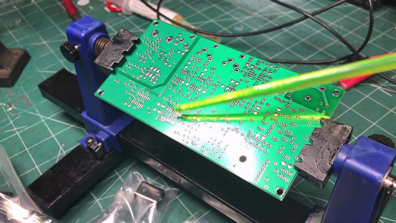
This video series will be for the Ensemble RXTX radio available from fivedash.com:
http://fivedash.com/index.php?main_page=product_info&cPath=1&products_id=7
WB5RVZ.org Build Site. Apologies for getting the call wrong in the video. Very comprehensive
http://www.wb5rvz.org/en...
restive fjord
@normal drift I have to fix a problem with one of my nodes and then I am going to take your latest RFM69 stuff out for a spin. 🙂
I just updated from your repo.
normal drift
@restive fjord use the released version. No need to use my repo.
They should be the same but it has been released so I’ll soon get rid of my branch.
restive fjord
Oh, OK.
 rare lodge
I'm having trouble getting my AdaFruit BLE Sniffer set up. I can get the tool bar to show up on Wireshark, but it does not see the device. However, I do see the device in the system and CoolTerm can open the port and get bytes. Any advice on how to set that up in 2020?
rare lodge
@strong scaffold I'd start wtih Getting Started with Bluetooth Low Energy by Kevin Townsend etal.
 strong scaffold
Thanks
normal drift
Wow! I guess "line of sight helped " https://www.thethingsnetwork.org/article/lorawan-world-record-broken-twice-in-single-experiment-1 ⚡
plain grotto
@normal drift there was a small (understandable) mixup at the digikey factory I was shipped feather 32u4's instead of FeatherWings. They are on top of it though, replacements coming in a few more days then I can test the RFM9x PR
 hollow geyser
Does anyone know what the difference between a tracking source and a tracking generator is?
I know what a TG is but have never heard the term Tracking Source.
I am looking to do return loss measurements of an antenna in the 5GHz neighborhood.
 young cove
@hollow geyser maybe the TS is set manually?? which spectrum analyzer is this? I'd guess the manual explains the difference
hollow geyser
I was looking at a HP 8595E. Manual: https://literature.cdn.keysight.com/litweb/pdf/08590-90301.pdf?id=1000000079-1:epsg:man
I didn't see it in there and since the manual is OCR'ed the term doesn't show up by searching for it.
They talk about the TG starting on page 86 but there is no mention of Tracking Source.
young cove
@hollow geyser I searched for the word "tracking" and there's a mention of "external tracking source" (I lost the page number). The tracking generator is option 010 or 011, and there's a table somewhere that shows one of those only goes up to 2.9GHz. That matches the chart above. So they must be talking about an external tracking source, not using option 010 or 011.
hollow geyser
That makes a lot of sense.
shell moat
I'm trying to determine if the Bluefruit (Adafruit_BluefruitLE_nRF51) library supports running as a Central (ie. Master). All of the examples appear to be Peripheral/client based ...
is it true that the Bluefruit nRF51 library only works as a Peripheral!?
I'm trying to use my Grand Central Express M4 with the bluefruit spi friend to be a Central/master, then have multiple other arduinos run as peripherals to the grand central ... so that they can "network" for a robotic game that I'm writing.
Ugh, ok, I found a definitive answer in the BLE FAQ. It says NO. Honestly, seems like a big miss everywhere else in the doc, including the hardware description.
restive fjord
@shell moat Take a look at the nRF52840 and associated libraries. This is the newest stuff, but I do not have any experience with it. I do have a Bluefruit SPI Friend, but have not done anything with it yet.
shell moat
The bluefruit spi friend is nRF51 ... so the older libraries. Even the newer nRF52 libraries have a warning on them saying that they're focusing on Peripheral, and that Central stuff is there but only lightly tested. In this case, I should have just gone with a cheap HC05 and common libraries. Now I'm thinking NRF24L01 which is probably a better fit all around. cheaper/faster/simple.
plain grotto
Is there any practical difference in choosing 868mhz or 915mhz on the devices that allow either?
primal warren
Mostly your local radio frequency usage regulations and antenna matching
plain grotto
Is there an easy visual way to tell the difference between the RFM69HCW Feather Wing like this: https://www.adafruit.com/product/3229 and the RFM95W Feather Wing like this: https://www.adafruit.com/product/3231

Add short-hop wireless to your Feather with these RadioFruit Featherwings. These add-ons for any Feather board will let you integrate packetized radio (with the RFM69 radio) or LoRa radio ...

Add short-hop wireless to your Feather with these RadioFruit Featherwings. These add-ons for any Feather board will let you integrate packetized radio (with the RFM69 radio) or LoRa radio ...
In the first few photos the RFM95W Feather Wing has a metal shield over most of the green add on board. But not in all of it's photos.
Is that a difference in revisions of the same product? or is the shield indicative of a different product?
restive fjord
@plain grotto 915MHz is for the USA and I think 868MHz is for Europe.
plain grotto
Thank you
normal drift
I think the metal shield is a recent addition. From the product page - https://www.adafruit.com/product/3231 “As of Jan 23, 2020 - The module now comes with a nice tin on top. Functionally, it is the same exact module, but now protected with a metal cover”
Add short-hop wireless to your Feather with these RadioFruit Featherwings. These add-ons for any Feather board will let you integrate packetized radio (with the RFM69 radio) or LoRa radio ...
plain grotto
Ah, I see thank you
plain grotto
On the Radio Featherwing I see here: https://learn.adafruit.com/radio-featherwing/wiring that I am supposed to use a few little wires to connect RST, CS, and IRQ to A,B,C,D, E, or F (or a few other pins I think) because different Feathers may have different pins available so it needed to be user selectable. But when I look at the example circuit python code a few pages further in the same guide: https://github.com/adafruit/Adafruit_CircuitPython_RFM9x/blob/master/examples/rfm9x_simpletest.py I don't see any references in that code to an IRQ pin being declared or used. Is there anywhere that will tell me more specifically what the IRQ pin is used for and whether it's needed for use with Circuit Python?


GitHub
CircuitPython module for the RFM95/6/7/8 LoRa wireless 433/915mhz packet radios. - adafruit/Adafruit_CircuitPython_RFM9x
normal drift
@plain grotto It is not used for the CircuitPython examples. It is used for LoRaWan and for arduino. I have also tried using interrupt on the RaspBerry Pi with CP with limit success...
It is used to trigger an interrupt on the completed transmit or receive so you don't have to poll for it. Since CP does not support interrupts in Python ....yet, it is not used.
plain grotto
Phew, thank you. I was coming to that conclusion (that it wasn't used) but wanted to be sure.
Ah, I see that makes sense. Thank again. I've got all the right devices now. Hoping to get the RFM9X PR tested tonight. Need to solder a few more pins and antennae wires then I'll be ready to go.
normal drift
here is how I wire mine for use with both CP and Arduino
CS -B
IRQ - D ```or solder in header pins so you can just apply jumpers as desired.
plain grotto
Oooh, that is a neat way to do it. That way it remains selectable
I like the curled antennae too.
normal drift
https://www.adafruit.com/product/4269 and there isa 433 MHz version but it does not look like Digi-Key stocks the 433 MHz version 😦
plain grotto
🎉 📻
Received (raw header): ['0x1', '0x2', '0x1f', '0x40']
Received (raw payload): bytearray(b'response from node 2 31')
RSSI: -22
That’s a retried packet. First ack must have failed!
plain grotto
You can tell from the 0x40 in the last element of the header right?
plain grotto
It seems like the one of my devices (the Edge Badge) is getting needing the retry far more commonly.
it feels about 10 0x0 to 1 0x40flags on the PyGamer and the opposite on the Edge Badge. I'll try swapping the wings to see if it follows.
normal drift
You can try increasing rfm9x.ack_delay
Or increase the delay before responding to a packet.
plain grotto
The tendency to have the retry flag stayed with the host device Edge Badge (node2) is still getting far more retry flags than the PyGamer node1. Okay I'll tinker with them some more later. The retry seems to work very well on them. Thank you for implementing all of this again!
normal drift
Glad it is working! There are a lot of “knobs to tweak” for better or worse...
💤 time here . Good night!
plain grotto
See ya. soon for me too
plain grotto
@normal drift I started working on a rudimentary serial based CLI messaging system built on top of your library modifications. https://github.com/FoamyGuy/CircuitPython_Radio_Mail_Serial_CLI/blob/master/radio_mail_serial_cli.py It still needs some work but the first messages have been successfully sent, received, read, and deleted  📻
📻

GitHub
Contribute to FoamyGuy/CircuitPython_Radio_Mail_Serial_CLI development by creating an account on GitHub.
normal drift
@plain grotto Nice! Look forward to playing with it.
 dawn pumice
can i use the bluefruit le uart friend to make my circuit playground express bluetooth compatible?
dawn pumice
hello?
plain grotto
@dawn pumice I think it depends a little bit on what you mean by "bluetooth compatible" is there something specific you are hoping to be able to do?
Also are you trying to use Circuit Python or Arduino or something different to program the Circuit Playground Express?
I don't believe you will be able to plug in in the bluefruit le uart friend to a CP Express and have it start behaving like the Circuit Playground Bluefruit with it's bluetooth capabilities. But I think you could perhaps write a custom program that makes use of the bluefruit le uart friend for a specific purpose like UART Service, or HID service etc... But it may be somewhat difficult. Unless I am missing something I don't see a Circuit Python library for that device. So if you are hoping to use Circuit Python you might have to deal with the low level commincation of the AT commands supported by this device, rather than having a nice high level library. I am not certain though.
 gray badger
Hey, I'd want to get 8 kbit/s with a 433MHz LoRa Wing. Obviously I want to stay inside legal limits (here in Spain it's 10% duty cycle, 10mW output power). Does it sound reasonable or will I have to drop to FSK mode?
I'm aware you can do things like frequency hopping and maybe some fancy things on top of that, but maybe it's not "good radio etiquette" to keep occupying the spectrum.
granite spear
I think the 10% duty cycle will be a problem. As I recall LoRa maxes out around 20kbps for full link utilization.
strong scaffold
@gray badger have you heard about LoRaWan its lora implementation but most of the stuff is already made for you some power saving measures like adaptive frequency scaling and transmission power and iirc they have legal limits built in for most countries
you can use Raspberry pi (with some additional hardware ofc) as LoRaWan gateway, and if desired info can be sent to any LoRaWan cloud service online (most are not free but there is things network which is free with restrictions)
or you can manipulate LoRaWan packages yourself, I think they are just json files
gray badger
Yeah I know about LoRaWan, but I want to avoid as much overhead as possible (the connection will be point-to-point anyway). It's just for experimentation purposes, so I don't need much of the features it offers but I want the maximum raw throughput
strong scaffold
if you dont mind me asking why you need that much throughput?
gray badger
(btw my idea is to link two GameBoy with a cable link adapter which sends the signal through LoRa. AFAIK the protocol is so timing-sensitive I cannot expect it to work, but the guy behind TCPoke managed to get Pokémon through the internet. Also, the GameBoy serial clock can be forced into slave mode so I can handle a lower bitrate, but I'm not yet skilled enough to know)
I was just doing that 😛
strong scaffold
thats cool
tbh too complicated for somewhat of a simple thing but great academic project
should be learning a lot
gray badger
As you can see is nothing serious or to be used in any professional solution, so I don't mind going outside the standard path for learning purposes
But I wanted to check with people actually using these modules if what I was trying to do was at least sensible or I was just nuts
strong scaffold
I dont know much about these but it feels like %10 uptime is not enough
data rate probably less problem than connection loosing because of legal radio use
gray badger
I'd be happy with zero loss at ~500m, enough to cover my village
Or maybe I could forger duty rate, and use 100% of the channel but only for 10% of the time? It's counted hourly here
(so 6 minutes of full-speed full-power communication! 😎 )
I'll have to look into frequency-hopping, it seems the only way to pull out this. Making both ends agree on which channel to hop into (taking into account any channel can be occupied and that I don't have too much airtime available) will be interesting to solve...
strong scaffold
Playing Zelda 4 swords 6 minutes every hour
dawn pumice
@plain grotto
bluetooth compatible in the most basic way, transmitting bits to and from the adafruit
the use im going for right now is to be able to connect to the CPX and send it a number indicating which position in a list to write to and then the value to write (0 or 1)
im essentially trying to use the CPX to emulate being an NES controller so that I can use it as an adapter to all sorts of random things as a controller and so i can write some software to send inputs to the NES
then on the clock pulses it can feed the data from the list into the NES
currently im using circuit python but I dont have any problems with switching to arduino
I was hoping to use it kind of like it says in the description, as a fancy pants wireless uart adapter, i was thinking i could plug it into the CPX's serial ports
gray badger
1 mW is allowed 100% duty cycle. How far can it get me w/ good antennas on both ends and clear line of sight?
plain grotto
@dawn pumice I see. I do think it would be possible to do that with it but I think the code in Circuit Python might end up somewhat "clunky" and there don't appear to be any examples to work from so you'd need to dig into and understand the underlying AT commands of that device. I would recommend trying to get a Circuit Playground Bluefruit instead if you can. It's got bluetooth built-in to the Circuit Playground form factor so you won't need to connect an extra device to use BLE functionalities. And there are Libraries for writing the Circuit Python code for it so you'll have a much better starting point.
dawn pumice
i dont know if I will be able to get a bluefruit, seeing as they arent in stock, would a feather be able to do the same thing?
and aren't the at commands just some set up for the device?
@plain grotto
plain grotto
@dawn pumice any device based on an nrf52840 would work the same there is a Feather nrf52840, and a another on with some extra sensors
dawn pumice
thanks,
one other question
aren't the AT commands just used for configuration
plain grotto
To be honest I've never used a device like that with AT commands so I am not sure. But yes I think they are for setting up configuration of the BLE services and things.
dawn pumice
gotcha
dawn pumice
can someone point me in the direction of how to write a basic program that can utilize ble on windows
just needs to work at its most basic, connecting to a ble device and then sending some packets
dawn pumice
is there even a library for windows app dev using BLE?
plain grotto
@dawn pumice maybe this can help? https://pypi.org/project/PyBluez-win10/

I don't have much experience with it personally so I can't really offer much insight but it looks to be a decent option for making a program that runs on Windows and uses bluetooth communication.
dawn pumice
The question is is it compatible with Bluetooth low energy
Worth a shot
The first and only version listed is from 2018
So probably
It’s probably better to just use the BLE windows runtime api calls for C++/#
Or just test it with the adafruit ble python library on Linux or Mac OS
 remote blaze
In the AP_SimpleWebServer example code of the wifi101 library the string called currentLine is created to hold incoming client data, but in what command is that string getting data
restive fjord
@remote blaze This sounds like an Arduino sketch. Is that correct?
granite spear
Looks like it's in the currentLine += c; statement: each incoming character is appended to the line one by one, until it gets cleared by a newline.
remote blaze
Oh okay so those characters are constantly being added
that makes sense thanks
@restive fjord yep one of the example sketches from the wifi101 library
restive fjord
@remote blaze Have you tried asking about this in #help-with-arduino??
remote blaze
Oh haha I didn't realize that was there, I just saw radio and I just thought to come here
restive fjord
Center freq of 500 kHz CW filter on this Kenwood R599A is just a tad too high.
Really emphasizes s/n ratio, though.
dawn pumice
https://youtu.be/lWzUlqv4XNE
Did they ever make a follow up to this?

Quick preview of a fun hack I've been working on to reverse engineer the protocol for a Bluetooth low energy RGB light bulb. Using a Bluefruit LE sniffer I captured the BLE commands sent by the bulb's control app so I could reverse engineer and replay the commands myself. A ...
dawn pumice
anybody?
 olive hill
Hello everyone! I need help ASAP. I've created a custom electronics package for a rocketry project that uses the RFM95 LoRa radio. There are three boards with flat ribbon cable interconnects between them. Everything except the radio functions and I've narrowed it down to a signalling issue, I think. Both hardware and software work flawlessly.
My working theory is that the SPI clock speed is too high (the RadioHead library defaults to 1 MHz) and that is creating interference for the MOSI and MISO lines right next to it. Does anyone know how I can lower the SPI frequency on an ItsyBitsy M0 or the RadioHead RMF95 library?
primal warren
It may be sufficient to just slightly slow the rise/fall times to reduce the harmonics. Alternatively, move the antenna away slightly and/or use shielding.
 hard wing
@olive hill Is this an HPR application?
olive hill
@hard wing HPR?
hard wing
@olive hill High Powered Rocketry.
olive hill
Not really. Using Estes E motors for 100-250m AGL apogee.
@primal warren figured out the issue. The radio wasn't working because of some bad soldering on a board interconnect upstream of the radio. It's operating normally now. Thank you for the advice though!
hard wing
Ah, ok! I'm building a flight controller for HPR applications. Controls staging and apogee detection for drogue deploy, and then altitude for mains deploy. Mine's just a little one - 20,000 feet. Our big ones hit 250,000+ feet at Mach 3-ish.
primal warren
Ah, that's annoying, but an easier fix than shielding/snubbing/rerouting.
olive hill
@hard wing holy cow, that's just a tad bit more powerful lol.
@primal warren absolutely. Now just have to redesign the control board because I forgot proper level shifting 😅
primal warren
Seems like your flight controller will need to withstand some G forces
You might be able to bodge on some level shifting (it's just a couple of parts)
 alpine bone
is there a way to see what inputs a Bluetooth devices causes? i am trying to use a remote with the raspberry pi.
 tribal nacelle
@alpine bone It'll probably help folks understand the issue better if you put a link to your Bluetooth device here
alpine bone
it is a very unused bluetooth remote. the link is https://www.amazon.com/Cynoculars-Virtual-Reality-Headset/dp/B01LKZA7FQ/ref=sr_1_1?dchild=1&keywords=Cynoculars&qid=1590613920&sr=8-1
i couldn't find an official site
primal warren
Just pair it with your laptop and see how it identifies and what it sends.
alpine bone
is there a certain way to do that? it is meant for games, and might send unique signals.
tribal nacelle
@alpine bone do you have an Android phone? perhaps something like https://play.google.com/store/apps/details?id=de.kai_morich.serial_bluetooth_terminal&hl=en_US will help determine what is being sent, probably an equivalent app for iOS.
alpine bone
sadly, i have an iphone, the least maker-friendly phone of them all.
tribal nacelle
https://apps.apple.com/us/app/get-console/id412067943 looks similar, I'm just Googling, not sure if this method will help but the price is right 🙂
alpine bone
i believe that app is for wifi things, based on the comments
tribal nacelle
sorry, how about https://apps.apple.com/us/app/bluetooth-terminal/id1058693037

App Store
## Apple Watch Support now available ##
Bluetooth LE Terminal is an App which allows you to test Bluetooth Low Energy enabled Devices.
For example: You want to build an accessory for an iPhone or iPad with Bluetooth LE. You want to test the hardware even before you develop...
alpine bone
that one is perfect! now i just need to learn to use bluetooth... (there are plenty of guides on the adafruit learning system) thank you!
tribal nacelle
you are very welcome, hopefully it'll provide clues as to what is being sent
dawn pumice
so im running into a couple problems with my flora ble friend
it works fine just sending data back and forth in data mode
but the AT commands don't seem to be working
i set the switch to data a mode, the light is blinking 3 times, and i tried a firmware update, but for whatever reason its not replying to the commands
im using a circuit playground express, tx wired to rx, rx wired to tx, gnd to gnd, 3.3v to 3.3v
im using this code
import board
import busio

uart = busio.UART(board.TX, board.RX, baudrate=9600,)
command = "AT+GAPCONNECTABLE=?"

a = bytes(command, 'utf-8')
uart.write(a)
uart.reset_input_buffer()
while True:
    data = uart.read(32)  # read up to 32 bytes
    if data is not None:
        data_string = ''.join([chr(b) for b in data])
        print(data_string, end="")
and im getting this as output: LE=? (and if i remove the wipe input buffer i see all of the command i issued)
i should get OK in response
same thing with other commands, i get the last three or four characters
also worth noting but may not have to do with the problem, the nRF toolbox and bluefruit le connect on my iPhone can connect and talk to the flora ble friend, and windows can see and connect, but it doesn't show up in bluetooth settings on my iphone
Anyone know what might be going wrong with the AT commands?
primal warren
You might need to write a carriage return and/or linefeed at the end of the command.
command = "AT+GAPCONNECTABLE=?\r\n"
I just had the same thought, I’ll try it in the morning and let you know how it goes
Ty!
dawn pumice
yep that was it
still don't understand why it shows up in bluetooth devices on windows and in my iphone apps for uart, but not in other devices on my iphone
thank you for the help!
It is set to be connectable and I started advertising, but still nothing
 cunning widget
I know that Bluetooth Classic and BLE are very different standards I'm wanting to create a "smart and Nerdy Watch that among other things can use bluetooth to talk (voice) to someone over the phone I know streaming voice is doable via Ble but that their are many BT classic devises on the market but I don't know if there are any libraries for me to do this. If there is a CircuitPython Library then that would be awesome especially if it will run on adafruit's nrf52840 series of boards. If I need to go back to Arduino language to do this that that will be Ok - although I prefer python.
it would be great to know if nrf52840 boards are capable of Bluetooth classic
granite spear
They are not, unfortunately. All the nRF chips are BLE only.
primal warren
Even the nRF8001?
granite spear
I believe so. The "Bluetooth Smart" label is another branding for BLE.
 tawdry mist
Hello. I am new to bluetooth and working on making a BLE connection between a feather m0 bluefruit and a mac in python.
I tried using uart_service.py from the adafruit proof of concept python wrapper (https://github.com/adafruit/Adafruit_Python_BluefruitLE), with the bluefruit bleuart_cmdmode example, but it gave me an error (attached image). Seems like it is not able to gain access to the mac bluetooth module.
It worked okay on my raspberry pi 3 B.
Anyone know what to do? Or someone who can possibly point me in a better direction? I have also tried using bleak (https://pypi.org/project/bleak/) where I was able to scan for nearby BT devices, but unable to detect the bluefruit.
I am using python 3.7 on macOS 10.14.6.
 dreamy glen
Hmmm I'm looking for a 433khz all in one oscillator datasheet, anyone knows where to find one?
Like a general one cause the model I have don't seem to be findable/available
To be more specific, I refer this kind
One says epcos r707 cmsn the other is unreadable
primal warren
I suspect that's a SAW resonator and not a whole oscillator
Perhaps this is what you're after? https://www.mouser.com/catalog/english/101/930.pdf
dreamy glen
seems like it . . .
the thing i'm trying to do is instead of using the included controller of the remote i want to use a esp32 to controll gates whatever code are they
the objective is to make a universal wifi 433 khz remote
primal warren
Sometimes it's easier just to buy a 433kHz transmitter module like https://hobbycomponents.com/wired-wireless/617-433mhz-wireless-transmitter-module-mx-fs-03v
dreamy glen
hmmm sadly my local shop doen't seem to have it . . .
either it's not listed on their site or they just don't have it, plus i'm gonna ebe able to go there only in a month or os i think
so osmething owrking rn woud be nicer . . . that's why i wanted to try to directly go wiht thta pcb/components
primal warren
That circuitry is fairly sensitive to layout, but it should be doable.
dreamy glen
what if i just unsoldered the microcontroller on the remote and just added a jumber to the esp32 where it would controll it?
primal warren
That's probably the quickest way forward
dreamy glen
hmm nice
ty
tho now how about reciving?
cause i know that thta board is able to recive too, to record the codes
primal warren
Perhaps the circuitry is on there too then?
 lavish valley
I'm typing to build my own fm radio how do I do that
Any good schematic
I think i have most parts
primal warren
Do you want to do the simple approach (slope detector) or the fancy one (ratio detector)?
lavish valley
Can you explain ratio VS slope
primal warren
A slope detector works by tuning the radio to the edge of the passband, so the varying frequency causes a varying detuning, thereby changing the voltage recovered and demodulating the signal with no extra parts.
I'm fond of this schematic
primal warren
Heh, you didn't specify 🙂 There ought to be some transistor designs out there too.
lavish valley
Yeah
primal warren
There are also FM tuner ICs out there, but they're more like "use an IC" than "build a circuit".
lavish valley
I don't want ics I want to build from scratch
Also I hate smd so small
primal warren
You might look up the "pendelaudion" circuit: it's fairly straightforward and can work well.
lavish valley
Will is sound good
I mean I was thinking to use the lm386 amplifier at the end
primal warren
The pendelaudion circuit works well and sounds good, and is fairly easy to build, but takes a fair amount of fiddling to get it working.
lavish valley
See what I can put together I will ask questions later if I don't understand 😅
primal warren
One popular FM IC is the TDA7000, if you want to look at that approach.
lavish valley
Is it pin through hole tho
primal warren
Yeah, it's available in an 18-pin DIP package.
It's been around forever (patented in 1977) but it's pretty solid, easy to use, and works well.
lavish valley
This looks Promising
primal warren
That looks like the basic pendelaudion circuit.
lavish valley
That bf451 transistor can i use whatever npn transistor
Or is is something special about it that I need just that
primal warren
Hmm, I'm used to seeing a BF541 in that circuit, I wonder if that's a typo. You need a reasonably fast (that's the "F" in the part number) transistor there.
lavish valley
Or is that pnp
Whatever
primal warren
Ah right, the BF541 is the NPN version, the BF451 is PNP.
lavish valley
So f means fast alright
You think i can use whatever transistor I have
Maybe I have that one haven't looked
primal warren
Yeah, first letter A is germanium, B is silicon. Second letter C is small signal audio frequency, F is small signal high frequency.
primal warren
A common 2N3906 might work.
lavish valley
Ok
lavish valley
That variable capacitor how do I wire that up looks like all 4 is in parrarel in 2
Mine has 4 pins and a ground
lavish valley
@primal warren also do you think a bc 557/ bc556 would work
primal warren
Yeah, that's a Colpitts oscillator, so it has 2 sections, in that schematic, it's shown as 4. They're all ganged, so they're turned by the same shaft.
lavish valley
So I should just connect all 4 together
primal warren
I don't know if a BC557 would work or not, the "C" transistors are designed for audio use and may not have much gain at higher frequencies. However, newer transistors are often higher performance than older ones, so if it's of recent manufacture, it may work.
I just took another look, it's not a Colpitts arrangement, so the 4 just behave as a single capacitor, so try the one you have.
lavish valley
It's not used so I think so
I think it came with my arduino that transistor btw
I got it last year a whole kit
primal warren
A BC557 has a transition frequency of 100MHz minimum (150MHz typical). A BF451 has a transition frequency of 325MHz. So the BC557 is pretty marginal in that circuit.
primal warren
You can give it a try, but it may not oscillate. However, it might work at a lower frequency. The frequency is determined by the capacitance of the capacitor and the inductance of the coil: do you know the value of your variable capacitor?
lavish valley
I salvage it from a non working radio i don't really know
primal warren
As a wild guess, I'd say 365pF: more than ten times the capacitance of the 25pF unit specified. So your circuit may well oscillate with the slower transistor, but at a lower frequency.
Or the impedance may be too low and you'd have to add some turns (or a core) to the coil.
lavish valley
Do you mean L1
primal warren
A lot of variable capacitors have visible innards, if you can figure out about the size of the plates and how many there are, you can work out the capacitance.
lavish valley
Yeah I can see in
primal warren
If it has a lot of plates (a dozen or more in a stack), it's probably an AM unit (typically 365pF). If it only has a few plates, it might be a lower capacitance FM unit.
lavish valley
This is the board
Don't mind the holes I placed it wrong 2 times before but I can put components over the holes
primal warren
A typical 365pF AM tuner capacitor looks like this
lavish valley
It goes through
primal warren
Oh, yours is a fancy one! I can see at least 4 trimmer sections inside it.
lavish valley
Yeah
primal warren
It looks like the sort of 4-section unit used for both AM and FM tuning, so it probably has a couple of sections that would be about right for that circuit.
The tricky part is figuring out the pinout.
lavish valley
Yeah
primal warren
You didn't happen to harvest any transistors from the same radio?
primal warren
There's likely at least a couple that are high-frequency ones you could use (if they're NPN, you can just run the circuit from the opposite voltage)
Ah, that thing. Now I remember. Hopefully it has some discrete parts and not just integrated circuits.
lavish valley
I don't think it had it was not much Ics at the time most stuff was external
Mostly the amplifier
And other small stuff I don't mind
On the tuner board there's a c1675 and a c536
Anything useable
primal warren
C1675 is probably short for the Japanese type 2SC1675, a 125MHz NPN transistor. Not particularly useful for this particular circuit.
lavish valley
Oh
primal warren
Similarly, the C536 is probably a 2SC536, a 115MHz NPN transistor, also not particularly useful here.
lavish valley
I try to build this radio with parts I have at home
But I don't have all the parts
primal warren
Maybe start with an AM transmitter if you haven't built one before? FM transmitters are a little exotic and difficult to get working reliably.
primal warren
Right: start with something that's more amenable to building with scrounged parts, and use that to get some experience. Starting with the hard one seems like a recipe for frustration.
primal warren
It supports Class 1 (100mW) and Class 2 (2.5mW).
 spice meadow
It should however also be stated that for range calculations knowing the tx power is not enough. There are other factors that limit range such as antenna design, propagation environment, and interference making it very tricky to get a good numbers analytically. I would recommend that you measure.
primal warren
BLE stands for "Bluetooth Low Energy": by definition it is not "strong". What are you actually trying to accomplish? Perhaps BLE is not the right tool for your job.
granite spear
For selecting a module, a "Class 1" Bluetooth radio goes up to the maximum 100mW transmit power level. You can also get longer range through choice of antennas.
spice meadow
@primal warren It is a bit of misleading acronym. It is made for IoT and IoT may require substantial range while still maintaining low power. Sure range is governed by tx power to a large extent, but a lot of things can also be accomplished with clever use of modulation and coding schemes that favour robustness over data throughput, and this is what BLE has done.
I would definitely use BLE for stuff like controlling robots at range (at least until the cellular iot protocols become readily available) but it should be made clear that you cannot expect to stream HD video froma robot using BLE. It is not built for that
primal warren
While I agree that IoT may require range, I'm not sure BLE is the right tool for that use case. I tend to look to other technologies for that.
spice meadow
Which ones do you prefer?
primal warren
I'm a fan of LoRa for point to point use, but I've also had good luck with ordinary ASK/OOK radios.
Was able to work across a large convention hall with this trivial wire antenna.
spice meadow
I remember I looked at this a few years ago and BLE was very attractive for some use cases. One thing is that it does not require underlying infrastructure (everything is d2d). It also has very nifty functionality for implicit clock synchronization of both devices (originally intended for audio streaming for regular bluetooth but carried over to BLE, and some robust variant of FHSS that made the signal quite robust against frequency selective interference.
I have only just recently learned about LoRa so I don't know a great deal about it yet. However it does not look very interesting imo since LoRa only encompass L1 functionality. L2 is the single most important aspect of wireless protocols and since LoRa relies on other technologies for L2 scheduling decisions I think it is quite a limitation.
I am personally more a fan of the upcoming cellular iot technologies (NB-IoT and CAT-M1). The L1 and L2 standards for them are solid. Once they get launched properly I think they will blow most other stuff away.
primal warren
I figure I'll wait and see on the cellular iot technologies. I generally use LoRa in a point-to-point mode with no additional infrastructure, it works just fine that way.
I'm able to get over a kilometer of range with short wire antennæ.
spice meadow
Just for reference the nbiot standard defines 10's of km of range for class 1 devices 😄
And these are ranges that must be met by the operator for them to be able to call the system nbiot.
primal warren
Yes, once things move to the cellular realm, different parameters apply. However, I'm regarding all that stuff as vaporware for now.
 quaint radish
Is there a feasible way to make an equivalent of a digital walkie-talkie based on LoRa, so up to 10 people could communicate in the neck of the woods (no gateway to the Internet)? Or is LoRa unsuitable and buying a modern digital walkie-talkie the still better solution? I have only used LoRa to transmit sensor data, but never looked into voice. Thanks!
strong scaffold
You can use LoRa frequency range just %10 of time legally it's like 6 minutes talking every hour I'd not say it's suitable @quaint radish
spice meadow
Yep, I agree. A voice application is fundamentally different from data in that longer periods of time is needed to transmit data (basically the tx needs to happen as long as PTT is pushed) and that can be quite long when a human is speaking. the 10% duty cycle is what kills this idea. Otherwise it would be quite suitable. I would recommend you guys to buy some cheap radios instead
primal warren
Depends on whether by "communicate", you mean "talk". If you want to just send text messages to each other, LoRa is dandy. If you want to digitize speech and pass it around, LoRa is not going to serve you well.
quaint radish
@strong scaffold @spice meadow Right, that sounds like LoRa walkie-talkies are unfeasible rumour projects, thanks!
@primal warren It was about talking and voice messages, like a digital walkie-talkie delivers, but LoRa is, as I understand, suited for something else, thanks!
lavish valley
i found a ic that should work for my diy radio just curious what is T3
primal warren
Looks like a tuned transformer of some sort (maybe an IF transformer?)
primal warren
Yeah, likely that sort of thing. I'm fond of the old TDA7000 for FM tuner use.
primal warren
Looks like a usual 10.6MHz FM IF transformer
lavish valley
ohhhh thanks
lavish valley
Hmm what now
Does the RF goes out through the coil
I can't Chinese so I don't know what it's saying
primal warren
You mean T3? The IF is coupled out through the coil, yes.
Yeah, you could condense things, but the wideband circuits will need to be properly arranged to work well.
cunning widget
I've noticed that a lot of the Ble examples using circuit python require you to be using an Apple device as a long time tinkerer android seems to fit my needs better. Are there CircuitPython libraries to use an Android phone that will allow me to make something based on https://learn.adafruit.com/ble-vibration-bracelet/coding-the-ble-vibration-bracelet ? I'm fairly sure I will be using the clue board. A seperate issue for the same project is can I send sensor data from the clue to the phone if so will I need to write an app for my phone to handle the different messages going between the clue and my phone?

Adafruit Learning System
Feel your iOS notifications with BLE and CircuitPython
lavish valley
I just follow the schematic I don't really know what it does or what I'm doing
Where should the IF go now
Should the IF go into this
Also am radio isn't that useful here so I won't lay time on making am
normal drift
@vocal veldt It has come up a few time recently that users are finding it very hard to use the rfm9x library on the feather_m0_rfm9x board since it runs out of RAM -- Do you think it is worthwhile to spend time trying to reduce the library size -- I did not think about size when I was working on it recently - I know I made it bigger (added a 256 byte buffer as well as code). Should we just give up on the M0 ... They are great for Arduino and RadioHead but very limited for CP. I use one for a very simple program that only uses the rfm9x library. It works OK, but I've never had much success using additional libraries with it so adding sensors does not work well. This is the latest discussion https://forums.adafruit.com/viewtopic.php?f=60&t=166139 I hope you did not mind my jumping
in
primal warren
@lavish valley Looks like the KA2263 goes after the demodulator, so you'll still need the IF strip and demodulator between your chips.
That would likely be your TA8108 chip. So the FM section goes TA7358 (FM tuner), TA8108 (FM IF/demod), KA2263 (FM stereo demultiplex), then PA.
lavish valley
what is pa
primal warren
PA is "power amplifier", the final stage that drives the speaker or headphones.
lavish valley
oh ok i think the lm386 would be fine for that
primal warren
That's a popular choice. Your existing unit might use a different chip or even discrete components.
primal warren
Then a little LM386 makes sense.
lavish valley
if im right the ta8108ap goes in after the if coil
it has am but i wont use that
if am isnt necessary to power it
primal warren
Yeah, looks like after the IF transformer, there's a resonator/filter then that chip for the IF strip and demodulator.
 vocal veldt
@normal drift I dont mind you jumping in at all, ever 🙂
@normal drift until we have a M4 LoRa board, I feel it's a worthwhile task to spend time reducing the rfm9x library size so it can function with additional libraries. I remember we once discussed freezing it into the m0-radio firmware - did that ever happen?
normal drift
@vocal veldt not that I am aware of -- I expect we'll have to trade of some other modules.. I'll try to take a look at both the library and freezing it over the next few days.
vocal veldt
@normal drift thanks for the assistance. iirc busdevice and rfm9x would need to be frozen into the build
lavish valley
Is this coil thing needed to the radio also what is this called
(I will not use this because it's broken if needed)
restive fjord
That's a bar antenna.
You can build an external loopstick type antenna, to replace it.
Or use a coil of wire (of proper dimensions) placed near the radio to induce radio signals into that bar antenna.
lavish valley
so basically its a internal antenna
restive fjord
Wikipedia calls your antenna loopstick; I'm thinking of a different kind.
Yeah it's used in lightning detectors and for AM radio (540-1750 kHz roughly, in USA) .. aka 'medium wave' for Yurrup.
It's a ferrite core with a winding around it.
Like a power transformer.
lavish valley
is it needed for fm
restive fjord
Not at all. ;) Unless ...
unless the designer somehow incorporates it into the FM RX circuit.
I think that's an unusual solution/choice, though.
lavish valley
then i dont need it am is pretty much useless here there is not alot of channels here on the am band
restive fjord
The long whip antenna on a portable receiver is for FM reception; there'll be a small loopstick inside the same radio for AM.
Why do you want to remove it?
lavish valley
idk is am even needed
restive fjord
AM is useful in Connecticut, USA during major storms when traditional communications are down/compromised, to get basic information.
lavish valley
i am in europe
restive fjord
It's also used for talk radio (baseball games for example).
I don't know how much the Medium Wave band is used in Europe at present.
The market nearly collapsed for Medium Wave in the USA, at one point, due to low fidelity.
normal drift
Hey -- don't belittle baseball by associating it with "talk-radio" 😉
restive fjord
lol
lavish valley
haha
restive fjord
You only need about 2300 Hz bandwidth for fairly effective speech-based radio communications.
High-fidelity audio takes a lot more than that.
lavish valley
Oh
restive fjord
DSL (telephone network based Internet service) leverages this fact .. the audio band is way low on the phone wire; and in a separate, higher band, the Internet service carrier is found.
Basically you filter out the Internet band to get your piggybacked telephony service.
They can't frequency-shift the telephony because it relies on legacy end-user equipment ('telephones').
So your old phones wouldn't work if they shifted the telephony out of the original band it was traditionally found in, when voice telephony was (almost) the only use of the POTS (Plain Old Telephone System).
So when DSL was deployed, they added to the system, but did not subtract anything useful.
Google for nyquist limit for theory on bandwidth limits. ;)
 tranquil pelican
anyone made fm crystal radio?
primal warren
I do want my old phone to work
FM crystal radio? That's an interesting concept. I guess it would have to use slope detection?
primal warren
You wouldn't need much, FM is in the VHF band.
However, slope detection is inefficient, high powered FM transmitters are less common than high powered AM transmitters, and the shorter wavelength makes it more difficult for an antenna to capture enough energy for a passive receiver. I'm not saying a crystal FM receiver is impossible, but it seems like an uphill battle to me.
tranquil pelican
yup
restive fjord
There's an electric appliance called a 'mixer' used in the kitchen, to stir batter for cakes and such.
A friend of mine in high school said the local AM BC tower was close enough to their house you could hear the station through that mixer, which is basically an electric motor. ;)
First hit on stackexchange:
https://electronics.stackexchange.com/questions/217083/simplest-fm-radio-receiver
FWIW analog radio receivers are notoriously difficult to construct for a satisfying experience, but when less performance is required, they're easy enough to demonstrate through use of simplified circuits.
Even commercally vended (through-hole construction) CB transceivers aren't usually known for good stability (required for enjoyable Single Sideband communications).
That's one reason why many CB's are AM only - easier to make and use without superb frequency stability (especially over many years' use).
primal warren
I don't think I agree that analog radio receivers are difficult to construct. Even a fairly basic circuit with an undemanding layout can perform well. There are also ICs (MK484 and similar for AM and TDA7000 and similar for FM) that simplify things further and give solid performance.
I will allow that FM receivers are more difficult than AM receivers as they're higher frequency, wider band, and have more complex demodulation, but they're still not that difficult to hand build.
Look up the "pendelaudion" circuit for details of a nice little circuit that will receive FM with just a handful of parts.
primal warren
Probably a voltmeter to serve as a tuning or signal strength indicator
I built this dual band hybrid AM/FM receiver a few weeks back, it worked well enough.
lavish valley
what is that types of blocks
primal warren
Those are Lectron blocks. http://www.lectron.de/
lavish valley
bruh out of stock
primal warren
Their factory is closed for the time being due to the pandemic.
There are other vendors of similar electronic building blocks (Brick'R'Knowledge, Snap Circuits, Gakken, etc.) but I like the Lectron ones the best.
lavish valley
is that good learning kits
there are more am stuff in this chip than fm it mostly goes throu it
primal warren
I really like Lectron as a learning kit (that's what I learned electronics on and I still use it). However, there are a bunch of other good kits out there as well.
There's a surprising amount of FM processing going on in that chip.
lavish valley
pin 16 15 12 11 9 an 8 is that the pins i should use just for fm
primal warren
Probably need pin 10 (supply) and pin 6 (AGC) as well.
lavish valley
how does the volt meter or whatever (V.M) look like
this is a bit of a pain but i really want to build this radio
primal warren
It's just a moving coil meter like https://www.adafruit.com/product/3990
Analog panel meters are arguably not as blingy or flashy as LEDs, but their simplicity adds a touch of elegance and makes them easier to read quickly.This Large 5V Analog Panel ...
primal warren
Yeah, you can get away without it.
You can skip the demultiplexer too if you don't care about stereo.
primal warren
Yeah, that decodes the stereo signal: if you don't need stereo, you might be able to get away without using that chip.
lavish valley
so i only need pin 16 15 11 10 9 8 and 6 right
normal drift
@vocal veldt I tried "freezing" the rfm9x module into the build and initially it overran the flash by more the 6K -- I took out a few other modules but it is still failing by > 2K -- not encouraging. I'll spend some time looking at the library before I go to far down this rabbit hole.
vocal veldt
@normal drift Woah, weird. I was able to freeze it and incl. with BMExx libs when I wrote the guide
@normal drift Are there methods, like the advanced methods, you could possible split out into smaller modules?
normal drift
probably -- I'll take a look and then create an issue to start tracking ideas.
vocal veldt
@normal drift ok, please let me know, ill be tracking this as well
normal drift
@vocal veldt I think both CP and the library have grown quite a bit. I'm experimenting in the library code today to see if there is low hanging fruit ...
vocal veldt
@normal drift ok!
lavish valley
@primal warren so what now what about pin 12 mpx how do i connect that when not using a meter
primal warren
I don't think you need to connect it if you don't want a tuning meter or stereo signal indicator.
cunning widget
I'm wanting to do a few things with BLE that the included examples don't cover dafruit's apps for android are able to send a lot of different info/data over ble to the microcontroler I'm wondering if there is a way to see the raw data of all data types instead of only the formated data for a few types with examples. I'm particularly interested in being able to send text to display on an attached display (using clue or feather nrf52840 with a display feather-Wing)
 fast isle
mmm any one do SDR ( software defined radio ) with a pi3B+
 cursive stratus

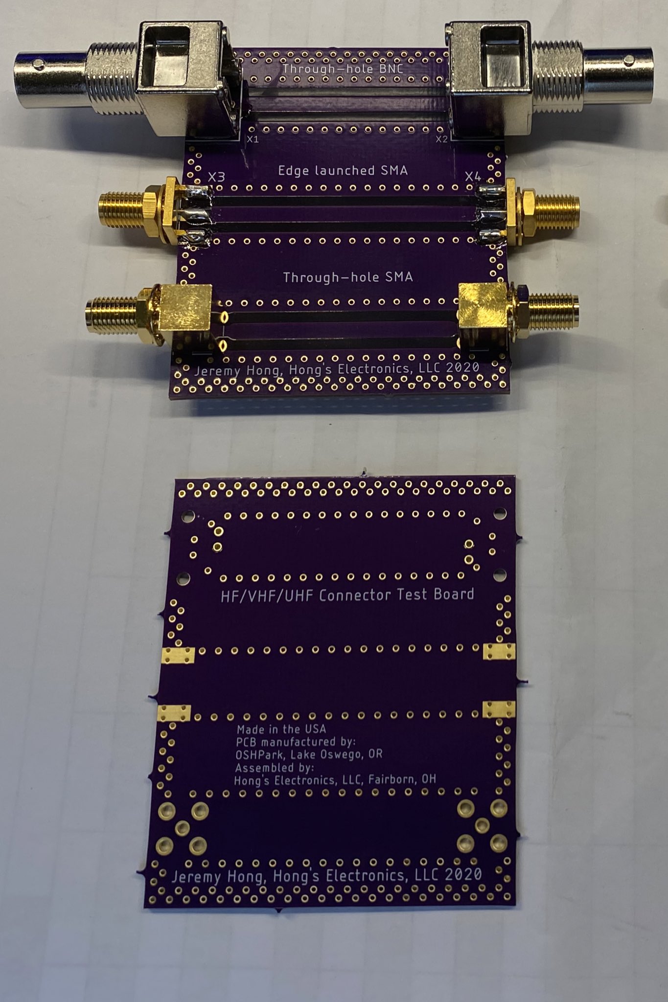
So the HF/VHF/UHF connector test board (Using @oshpark’s super swift service) looked fairly good for what I had designed for (~800MHz). I was curious to see what it would look like upto lower C-Band and wow! That edge launched SMA is actually very good!
 Twitter

Very cool analysis of connectors in pcbs.
 pastel iris
@fast isle I answered this post in the pi channel
young cove
@cunning widget a better place to ask about BLE and CircuitPython is in #help-with-circuitpython. I did a lot of the BLE work but don't read this channel regularly. I will answer over there.
vocal veldt
@normal drift Do you want to draft a release for RFM9x or should I? (noticed u did the last one, didnt want to step on existing work)
normal drift
Either way is fine with me -- you are welcome to do it.
or -- I'll be happy to.
@vocal veldt @slender current had some comment on the PR -- we should make sure they are resolved before releasing
normal drift
good questions! Not sure I have good answers.
slender current
isolating the changes to a smaller library could help
if unused const variables are included, fixing that could be a huge win for many libraries
normal drift
@slender current I'll try to test that with some "test" code -- would be a good learning experience. any objection to releasing this as is and working on that later -- Next I want to work on CP build for the feather_m0_rfm9x -- if it works the also the rfm69. It builds now for en-US, but only has 222 bytes left -- not sure it will work for all languages. I can take out analogio to see what that allows and play play a bit with some of the CFLAGS settings.
There is no rush to release this -- if you prefer I do more on the size reduction first.
slender current
releasing is fine with me
I'd love to have a better understanding of why it improves memory use so we can apply the changes more broadly or improve the core
normal drift
@vocal veldt Lets hold off on releasing until I get the CP build settled -- If I have to do more I'll create a new PR. I just wanted to have it merged so it can be linked into CP
Do you have any concern with removing analogio from the cp build?
vocal veldt
@normal drift Not personally. Only issue I could see is people using photoresistors + lora
most modern temp sensors are i2c
normal drift
the zh_Latn_pinyin translation fails by ~700 bytes with analogio but passed by 372 with it out. Its either analogio or neopixel_write....
vocal veldt
@normal drift i vote analogin
normal drift
ok -- will try -- de_DE build failes by 76 bytes even w/o analogio ... still trying to squeeze
vocal veldt
🤏
normal drift
🔨
normal drift
@vocal veldt How do you feel about removing pulseio? It would men no DHT11/22 -- but its big?
or maybe not -- dht driver will bitbang if no pulseio -- i can test that
vocal veldt
@normal drift DHT11/22 are commonly used w/IoT projects, i'd be hesitant to remove if it doesnt use pulseio.
normal drift
but will the bitbang option work -- just about to test it
does not seem to work 😦
hmm dht22 does not work even with pulseio on thisi board.....not sure what is going on.
normal drift
ha! found an issue with the DHT on M0s -- this may still work -- will see after the issue gets resolved - may be a CP , not driver issue https://github.com/adafruit/Adafruit_CircuitPython_DHT/issues/45
 somber grotto
Hi, I'm project raspberry with Arduinos with sensors and communications using radio NRF24L01, any recommendations and examples?
 bold flax
 somber grotto
OK, thanks.
 gaunt kiln
hey
 broken sinew
Does anyone have experience w/ the raw RFM 95 chip? Without the breakout board?
I wired a pair up to my nanos and tried to test a two way comms setup (one receiver and one transmitter). Transmitter works but it doesn't seem to receive- any thoughts?
Also posted in #help-with-arduino
granite spear
I'm not quite sure what you mean by "raw"... do you just have a SX1276 chip and associated RF circuitry on your own board? Are you using LoRa or the other radio modes? There's unfortunately lots of potential things that might prevent an end-to-end link from working.
 clever verge
with adafruit shield thingie
without shield
Hi @broken sinew bob11334. I had the same problem with the 'test' code. I was using the rf9x without shield and had to make sure the pins were correctly corresponding with library.
I also have the same question concerning these two boards. how do they differ? other than the one being way easier to connect with arduino due to pin spacing.
Can they do the same stuff? If you provide 3.3V.
clever verge
(Referring to RFM95 for both. Want to know what the adadruit shield does, in short.)
sorry didnt check pictures before uploading 😉
normal drift
here is the schematic for the breakout board -- same for RFM69 and 9x, I believe https://cdn-learn.adafruit.com/assets/assets/000/031/773/original/adafruit_products_schem.png?1460752861

 charred plaza
so the breakout basically just prepares it for 5V use?
clever verge
Thanks for sharing. I am using adafruit itsybitsy M4 so am already at 3.3V. I will continue using LoRa without breakout as it doesnt do anything special.
normal drift
Good luck with it!
broken sinew
@clever verge Hey, sorry for the late response. Can you clarify how you solved your problem?
Here's a fritzing of the setup as it stands- can you point out what I'm doing wrong?
broken sinew
@granite spear Just the SX chip and a spring antenna, you can see the attacked fritzing diagram for more info
Quite a basic system I'm afraid
clever verge
Give me some time i will get back to you;)
clever verge
@broken sinew can you also send me a copy of the code that you are using? maybe I can look at that. Later today or tomorrow I will be working with LoRa again then I will send you details of my sketches.
broken sinew
I'm just using the test code off adafruit
clever verge
your wiring looks fine. I am not using the same board tho, so I cant tell you exactly.
broken sinew
Lovely to hear
Yeah I'm just using the test code for benchmarking, then I'll swap over to custom sketches
clever verge
Ok I had to modify the test code a bit. I havent got time to get into it now, but I will let you know when I do. I will share a pdf that really helped me, maybe you can use it to fix your project.
 tidal kiln
how can i make the errors section in the arduino ide smaller ?
primal warren
You can just drag the divider bar up and down (at least in some platforms)
 true venture
let me know if I should ask this somewhere else. I'm working with an nRF52840 feather, using nRF's SDK, and want to be able to have two devices (BLE peripheral + central) connect and "bond" (is that the word?), so they can always reconnect in the future. it seems like the "Peer Manager" library should handle this (it stores bonding info), but I can't figure out how to retrieve the necessary data to reconnect (something like a MAC so I can filter to the right device).
tidal kiln
@primal warren thanks a lot for ur answer
though, i minimized the section to its maximum but it is still big for me
primal warren
I think the minimum is 4 lines or so.
tidal kiln
let me check
@primal warren i fixed it yay
i was setting the font to a higher value than usual in the preferences
therefore the font in the error section is bigger
thanks anyways
primal warren
Ah, that would do it, and thanks for sharing your fix!
tidal kiln
@primal warren you re welcome brother 🙂 🙂
 quasi oar
Hello everyone. Trying to understand the operation of an example set of code and LoRa. Using a Feather M0 RFM9x, I'm running the standard "Hello World" example from Terry Moore et. al. I connect up to my gateway fine. The code sends two packets of data 1) the "Hello World" and 2) an empty payload. From then on it stays in the [OP_TXRXPEND, not sending] state. I was assuming it would have resent the initial "Hello World" payload again. Is there an acknowledgement that it should receive? What am I missing here?
normal drift
Do you have a link to the example? Is this Arduino or CircuitPython?
quasi oar
@normal drift Hey, there. Standby, I'll grab it. This is Arduino.
normal drift
This is the Arduino example I have used for LoraWAN-- but it's been ahwile https://learn.adafruit.com/the-things-network-for-feather
That is, are you trying to use LoraWAN via a gateway or just a local Lora transmit/receive?
quasi oar
I can't find where I got my example. It's the old one that has been around for awhile. Yes, I have a LoraWAN gateway that sends to TTN and then on to AWS. In any case, I'll jump over to the Adafruit examples. I used them when I was using the 32uF board which worked fine. Should have stayed on the straight-and-narrow. I won't waste anymore of anyone's time. Thanks Jerry.
normal drift
No problem. It's good to branch out! Good luck!
quasi oar
Just got to make sure to pick the right branch for your weight!
quasi oar
@normal drift Actually, that was the example I had used as well. I had just hacked mine up a bit to try and figure out what was going on. Unfortunately, using the stock code results in the same problem. It sends a couple of time and then stops and sits at [OP_TXRXPEND, not sending]. 😐
normal drift
hmmm -- I've had that code running for months....It looks like it is hanging trying to transmit
quasi oar
Exactly.
normal drift
do you have G0 connected? Probably would not get this far with out it.
on the M0_RFM9x -- of course its connected -- is the pin set correctly
quasi oar
You lost me on G0...
normal drift
the interrupt pin -- goes by several names G0, DI0
quasi oar
I see. I'll check that.
normal drift
it looks like it uses both DIO0 and DIO1
I have to go offline for the evening -- I can dig into this more tomorrow if you are still having trouble.
quasi oar
Thanks again for your help. I'll ping you if I get any progress. Have a good evening. @normal drift
quasi oar
@normal drift I got it going. It was IOHS on my part, I had not set the jumper correctly from io1 to pin6. I had inadvertently set it to pin5. Measure twice, cut once...
gaunt kiln
hey
broken sinew
Howdy 🙂
clever verge
@broken sinew Hi. ive managed to get my two way communication to work. hope the code helps.
This one sends first
broken sinew
@clever verge thanks for the upload! TFT is the LCD display, right? Can we safely suppress its use in the code?
What board is this based on? Looks like an uno?
tidal kiln
hi guys
does anyone
know how to hange the arduino ide language in the app files because i chnaged my ide language and it cant boot up
any helps will be greatly appreciated
tidal kiln
does reinstalling the ide reset its language ?
i dont mean the programming language guys
<@&617066238840930324>
i mean the editor language
primal warren
You can change it in the preferences dialog.
primal warren
First screen, second line.
tidal kiln
this is my preferences, where exactly @primal warren
primal warren
tidal kiln
ah i understand you rn , i changed the language of ide and it cant boot up
so i cant access t othat window no more
i wanted to know if there is a way to change the language in the preferences.txt
primal warren
I think it's the editor.languages.current= value
 umbral scroll
Hey guys
I'm testing out some nRF24L01s with Arduino
But I'm having some problems, I'm not able to get my setup to work
I have an Arduino Uno + one nRF24L01 as a transmitter and another Uno + nRF24 as a receiver
I believe there aren't any problems with the wiring
I'm using this library: https://github.com/nRF24/RF24

Code was directly taken from a blog called "HowToMechatronics": https://howtomechatronics.com/tutorials/arduino/arduino-wireless-communication-nrf24l01-tutorial/
Here's the transmitter code:
#include <SPI.h>
#include <nRF24L01.h>
#include <RF24.h>
RF24 radio(7, 8); // CE, CSN
const byte address[6] = "00001";
void setup() {
  Serial.begin(9600);
  radio.begin();
  radio.openWritingPipe(address);
  radio.setPALevel(RF24_PA_MIN);
  radio.stopListening();
  Serial.println("ready");
}
void loop() {
  const char text[] = "Hello World";
  radio.write(&text, sizeof(text));
  Serial.println("Radio write");
  delay(1000);
}
Here's the receiver code:
#include <SPI.h>
#include <nRF24L01.h>
#include <RF24.h>
RF24 radio(7, 8); // CE, CSN
const byte address[6] = "00001";
void setup() {
  Serial.begin(9600);
  radio.begin();
  radio.openReadingPipe(0, address);
  radio.setPALevel(RF24_PA_MIN);
  radio.startListening();
}
void loop() {
  if (radio.available()) {
    char text[32] = "";
    radio.read(&text, sizeof(text));
    Serial.println(text);
  }
}
Last time I tried this was about a year ago and I didn't have any problems. Could the problem be something to do with the library version...?
I would really appreciate some ideas for solving this problem, but I'm aware that debugging RF problems isn't the easiest thing to do. Thanks.
granite spear
So I don't see any SPI initialization. Is that necessary or already taken care of inside the RF24 library?
umbral scroll
I don't think that's necessary. I'm pretty sure the RF24 library takes care of that.
tribal nacelle
@umbral scroll I always wanted an excuse to fire up my nRF24's, I saw your post and thought I'd try them. I'm running the same sketches as above and I'm watching Hello World scroll by...
tribal nacelle
1.3.5, by TMRh20, right from Library Manager
umbral scroll
I installed TMRh20's library from his website
It does appear in the Libraries Manager, though
I believe I was using version 1.3.4 during my tests yesterday
umbral scroll
I think I'll try a reinstall tomorrow morning.
tribal nacelle
but it does appear the library sets up SPI
umbral scroll
Could you by any chance measure how much current the nRF24's are consuming?
umbral scroll
I was did some measurements yesterday just to see if my nRF24s were burned out or something
tribal nacelle
about the same on Tx
umbral scroll
They were drawing about 1mA, so if your modules are drawing 3mA with an LED i think my modules should be working fine
about the same on Tx
@tribal nacelle Thanks mate
tribal nacelle
Now I need a project to put them in 🙂
umbral scroll
An RC car is always fun to build
tribal nacelle
yeah, a buddy at work bought a ton of stuff for that purpose, got frustrated and donated to me. Guess I owe him a car 🙂
umbral scroll
Hahaha
tribal nacelle
he was going to use XBee modules, a nice trade
umbral scroll
The craziest thing I've seen so far with an nRF24 is a Wi-Fi/Bluetooth jammer
tribal nacelle
what just keep scrolling through all the channels?
at max power
I think a car is the direction I'll take...
umbral scroll
http://hugorezende.com.br/blog/jamming-wifi-signal-with-an-arduino-and-nrf24l01-module/
More details here

Disclaimer: This post is only for educational propose only. Jamming any kind of signal is considered crime in many countries. Some weeks ago started to look and understand better what is behind the Wi-Fi and Bluetooth technology, more specifically, over the electromagnetic w...
tribal nacelle
i'll have to check range (i have the lo power versions)
but if i ever get back to the office and somebody ticks me off... 🙂
umbral scroll
what just keep scrolling through all the channels?
@tribal nacelle I think the nrf24 targets a specific frequency and just spits out random noise
tribal nacelle
i'll take a look
umbral scroll
I think a car is the direction I'll take...
@tribal nacelle Best to play it safe, lol. I think wireless signal jamming might be illegal.
umbral scroll
i'll have to check range (i have the lo power versions)
@tribal nacelle I built an RC car with nRF24s last year. Just by eyeballing it I would say you could get a range of 20 to maybe 30 meters with the low-power modules (i used those in my car).
but if i ever get back to the office and somebody ticks me off... 🙂
@tribal nacelle Lol hahaha
tribal nacelle
good enough range (especially on only a few mA's
umbral scroll
did you maybe swap MISO and MOSI?
@tribal nacelle I'll check.
tribal nacelle
but the code is good as is, one less variable
umbral scroll
Yup
tribal nacelle
Now I have to dig deeper, oh well, not bored in quarantine anyway!
tribal nacelle
are you using UNOs?
umbral scroll
Yup
Still nothing. Darn
I'm starting to think some of my modules might be faulty
tribal nacelle
time to build the spectrum analyzer part of the jammer...
umbral scroll
Do you think that could help somehow?
tribal nacelle
it would tell you if module A is putting any rf out
unless module B is the broken one 🙂
umbral scroll
Since these modules operate at 2.4Ghz, could they might pick up the signal from my Wi-Fi router?
umbral scroll
+5 Volts? I don't think so
tribal nacelle
these little adapters i have incorporate a 3.3v reg
umbral scroll
Those adapters are quite handy
Unfortunately I don't have any
I think I'll measure the current draw of each module with only 3.3V and GND connected
tribal nacelle
but if you have the correct dupont wires it's easy enough without them
umbral scroll
Yup
tribal nacelle
I bought these years ago, but almost immediately started using wifi or BT
try adding some print statements to see where the code goes, is radio.available?
tribal nacelle
cool, i have an oled round here somwhere...
umbral scroll
This is what I get when I disconnect power from my nRF24 on the Rx side
Now I connected power, reset the Arduino and Serial Monitor and the Rx outputs this to the Serial Monitor
I don't understand exactly what the output's saying, but some things do change
tribal nacelle
and TX is running?
umbral scroll
For one, the lines I highlighted in blue have get printed periodically on the Serial Monitor
Some other parameters in the STATUS and ADDR and whatever change too
and TX is running?
@tribal nacelle Yup
I'll disconnect Tx now to see what happens
tribal nacelle
second example looks like Rx address is noise
umbral scroll
This is with the Tx disconnected
Somewhat different, but I still don't know what's happening
second example looks like Rx address is noise
@tribal nacelle How come?
tribal nacelle
that code isn't as well documented as I'd like
i was looking at RX Address near the top
on your first test it was 0x00
so maybe second example is good
need to dig into the library to see what radio.printDetails(); gives
umbral scroll
I think radio.printDetails() prints out things like STATUS, RX_ADDR, Data Rate, PA Power, etc.
Just guessing really
tribal nacelle
yes but what does status x mean? 🙂
the numbers at the bottom represent signal level on each of (126?) channels but it's not clear to me how
on the 1st example it was a sequence, not random data
umbral scroll
I think we can ignore the first two lines
Not sure
It just looks like it's looping though decimal digits on the first line and hex digits on the second line
I don't know what that means though
The rest just looks like really long random hex numbers to me
tribal nacelle
shows printDetails
i would think both Rx and TX would show address 1 in the Rx address lines above
umbral scroll
What does RX_ADDR_P0-1 and RX_ADDR_P2-5 mean?
Are those two different addresses for the receiver?
Why would the receiver have two addresses?
tribal nacelle
you can have up to 6 data channels (addresses) per "radio" as i understand it
I believe that is what the example sketches const byte address[6] = "00001"; sets, the channel the radio is using
so 0xe7 and 0xc2 seem wrong
with my TX still running and scanner on Rx:
opps got slapped...
umbral scroll
Crazy bot lol
tribal nacelle
RF24/examples/scanner/
STATUS = 0x0e RX_DR=0 TX_DS=0 MAX_RT=0 RX_P_NO=7 TX_FULL=0
RX_ADDR_P0-1 = 0x3130303030 0xc2c2c2c2c2
RX_ADDR_P2-5 = 0xc3 0xc4 0xc5 0xc6
TX_ADDR = 0xe7e7e7e7e7
RX_PW_P0-6 = 0x20 0x00 0x00 0x00 0x00 0x00
EN_AA = 0x00
EN_RXADDR = 0x03
RF_CH = 0x4c
RF_SETUP = 0x01
CONFIG = 0x0e
DYNPD/FEATURE = 0x00 0x00
Data Rate = 1MBPS
Model = nRF24L01+
CRC Length = 16 bits
PA Power = PA_MIN
just enough
so that makes sense, RX_ADDR is 0x31 or 1, then all 0's
umbral scroll
Hold up
the numbers at the bottom represent signal level on each of (126?) channels but it's not clear to me how
@tribal nacelle So each one of the lines that just looks like random hex digits is just the Rx displaying the signal strength on the 128 channels that the nRF24 allows for data transfer?
tribal nacelle
i believe so. try expanding the serial monitor out wider
umbral scroll
Serial monitor is fully expanded already
tribal nacelle
on mine i see only 0's after the opening sequence
tx on example, rx running scanner
the tx might be timing out
umbral scroll
Can you send a screencap?
RF24/examples/scanner/
STATUS = 0x0e RX_DR=0 TX_DS=0 MAX_RT=0 RX_P_NO=7 TX_FULL=0
RX_ADDR_P0-1 = 0xe7e7e7e7e7 0xc2c2c2c2c2
RX_ADDR_P2-5 = 0xc3 0xc4 0xc5 0xc6
TX_ADDR = 0xe7e7e7e7e7
RX_PW_P0-6 = 0x00 0x00 0x00 0x00 0x00 0x00
EN_AA = 0x00
EN_RXADDR = 0x1d
RF_CH = 0x4c
RF_SETUP = 0x07
CONFIG = 0x0e
DYNPD/FEATURE = 0x00 0x00
Data Rate = 1MBPS
Model = nRF24L01+
CRC Length = 16 bits
PA Power = PA_MAX
so that makes sense, RX_ADDR is 0x31 or 1, then all 0's
@tribal nacelle I don't understand what you're saying
tribal nacelle
how do you paste a jpg in here?
umbral scroll
Honestly, I'm kinda tired. It's 2:41 AM here in Brazil. Going to bed and I'll pick this up in the morning.
how do you paste a jpg in here?
@tribal nacelle I just take a screencap and use Ctrl + V.
tribal nacelle
lol, late here to, i think the hex is ASCII coded, 31 = 1, 30 = 0
yes it is late
i'll post what i'm seeing here tomorrow
nRF24_Scanner
umbral scroll
Swapped out module on Rx.
Not sure what all zeros means.
Finally
YEAH BOIII
I don't know what did it hahaha
The Arduino that was running as Tx yesterday is now Rx and vice-versa
I also changed the new Tx's nRF24 for another one i had lying around
Thank you very much for your tips @tribal nacelle !
tribal nacelle
No problem! it's working with original modules or you had to swap one?
umbral scroll
I had to swap at least one
tribal nacelle
ok
umbral scroll
(not gonna lie i lost track)
tribal nacelle
"No amount of software engineering will overcome bad hardware"
umbral scroll
True hahaha
tribal nacelle
OK, off to work, happy hacking!
umbral scroll
Added a counter to each received message
I'm happy to see it running : )
@tribal nacelle Thanks! You too
restive fjord
I hope this is the correct chat room: Does anyone know how to send just plain binary (e.g. create a plain binary Characteristic) using Adafruit_CircuitPython_BLE library?
broken sinew
Hey @restive fjord , if you dont mind me asking, why do you want to send plain binary?
 dusk vector
Anyone know of an iOS tool that will read and display a raw NFC tag? (as in like, the full memory structure)
tidal kiln
does the servo motor need a pwm signal to work ?
granite spear
Yes, typically. Sometimes they will also take an analog signal, or a more complex communication bus, but PWM is normal.
tidal kiln
thank you @granite spear
 sweet jungle
Hello. Having some trouble getting a Feather M0 with RFM95 LoRa to do the simple example at https://learn.adafruit.com/adafruit-feather-m0-radio-with-lora-radio-module/circuitpython-for-rfm9x-lora. When I try to define rfm9x = adafruit_rfm9x.RFM9x(spi, cs, reset, 915.0) I get the error "RuntimeError: Failed to find rfm9x with expected version -- check wiring". Pretty sure I have installed CP and libraries correctly. Thanks for any help.
granite spear
Can you clarify how you're setting up the SPI configuration?
sweet jungle
Let me just give you the whole example (same as on learn.adafruit.com)
Adafruit CircuitPython 5.3.1 on 2020-07-13; Adafruit Feather M0 RFM9x with samd21g18
import board
import busio
import digitalio
spi = busio.SPI(board.SCK, MOSI=board.MOSI, MISO=board.MISO)
cs = digitalio.DigitalInOut(board.D5)
reset = digitalio.DigitalInOut(board.D6)
import adafruit_rfm9x
rfm9x = adafruit_rfm9x.RFM9x(spi, cs, reset, 915.0)
Traceback (most recent call last):
File "<stdin>", line 1, in <module>
File "adafruit_rfm9x.py", line 260, in init
RuntimeError: Failed to find rfm9x with expected version -- check wiring
granite spear
The guide says:
However if you're using the Feather M0 RFM69 board with a built-in RFM9x radio (and you've loaded the special version of CircuitPython just for this board as mentioned above), you instead want to use these pins for the CS and RST lines:
reset = digitalio.DigitalInOut(board.RFM9X_RST)```Does that apply to your situation?Hmm. Yes, that worked! But I don't think it should have. I have this board: https://www.adafruit.com/product/3178, which I thought was not an M0 RFM69 board with a built-in RFM9x.
normal drift
@sweet jungle No tsure I understand -- that is an RFM9x
the pins names for the rfm9x M0 boards are RFM9X_CS, RFM9X_RST
sweet jungle
Thank you @normal drift. Reading the instructions for a simple Tx/Rx test at https://learn.adafruit.com/adafruit-feather-m0-radio-with-lora-radio-module/circuitpython-for-rfm9x-lora in the "Usage" section suggests that I have a "Feather M0 RFM69 board with built-in RFM9x radio"

Adafruit Learning System
Send your message really really far and wide
normal drift
@sweet jungle ah -- that is a typo!
sweet jungle
@normal drift so it should read "Feather M0 RFM95 board with a built-in RMF9x radio" then?
normal drift
yes -- I will fix that
sweet jungle
Thank you both @normal drift and @granite spear for your help!
normal drift
You are welcome -- Thanks for pointing that out. -- it is fixed now
sweet jungle
@normal drift Magic! Thanks.
 kindred dome
Does anyone know of a relatively cheap and decent quality RC transmitter/receiver combo or transceiver?
primal warren
The Turnigy 5X is a fairly good deal, 5 channel combo, can generally be had for less than US$30
 fossil sail
Does anyone know a mosfet that can switch at around 27MHz?
granite spear
That might depend on how you are driving it. MOSFETs are often characterized by gate capacitance, so if you have a strong driver, you can switch them more quickly.
 viscid tusk
You get mosfets that can switch at Ghz
 last merlin

viscid tusk
vocal veldt
@normal drift fwiw - I found there's a a port of CircuitPython TinyLoRa to MicroPython https://github.com/fantasticdonkey/uLoRa

GitHub
LoRa / LoRaWAN + TTN for MicroPython (ESP32). Contribute to fantasticdonkey/uLoRa development by creating an account on GitHub.
if anyone asks about TTN on ESP32 natively
 floral anvil
I have no clue what that component is nor what it does
Google failed me and gave me Syma X5C drones
granite spear
It looks like a capacitor, similar to the others around it.
floral anvil
Is there a way to identify if it's broken?
granite spear
It appears to be leaking, so yeah, it's probably broken.
tribal nacelle
is it a cap or a tilt sensor?
floral anvil
I doubt that it's a sensor
It doesn't have access to anything that can control it.
Is that not glue?
Oh wait
Does any of these look burnt?
granite spear
Not particularly...
floral anvil
Should I remove this? Underneath it silicon.
granite spear
That's likely a heat sink.
floral anvil
Could whatever that's under it be burnt?
granite spear
🤷 How could I possibly know that, heh heh?
floral anvil
.3. I will find out
 signal flume
I'm new here, nice to see I'm not the only one who is rough on things lol
floral anvil
Everything looks fine.
tribal nacelle
what does it do or not do?
floral anvil
Is there some sort of component app that helps you identify components?
tribal nacelle
sometimes the components have markings that help, sometimes not
if you know what it is you may find a schematic for it
floral anvil
This has no markings
Heard some noises from the adapter
I can smell something
The thing says output 5V
And a computer comp pushed 5V
Nvm
primal warren
@floral anvil the unmarked component looks like a crystal to me.
floral anvil
@primal warren Thank you so much! After typing Crystal in a application I found, the second page I found out what it was. Thank you again Jesus 🙏.
The crystal is a Abracon AB308-28.6363MHZ
 topaz ledge
Hi! Does anyone know of some super low power project that could passively listen for a signal to wake up from a low power state, then check to see if it is being "addressed". If being addressed, turn on an LED.
I am looking for a very small device that could receive signals over IR or over radio.
I am imaging a solution for a coat check where you'd decorate the hanger with one of these "things" and then when a person arrives with their tag, I could then light up the right hanger. Thoughts? And thank you!
primal warren
The TI "SensorTag" chips were designed for that sort of thing.
topaz ledge
Thank you. I'll take a look at those. Searching....
topaz ledge
Has anyone done any work or projects with the TI CC2650 family of devices? They look like fun! or (CC2652RB)
 twilit relic
Can the Adafruit Feather nRF52840 Express read from a Garmin ANT+ heart rate strap?
plain grotto
@twilit relic as far as I can tell ANT+ Seems to be a little USB dongle that reads data from workout devices, not an actual device itself like a heart rate monitor.
That being said. The Feather nRF52840 probably could read data from the heart rate monitor device if it uses BLE to transmit the data. However you may need to do some of the legwork to figure out and set up the proper BLE services and characteristics in order to get it working.
I would start by trying to find out if Garmin provided any API documentation for the device you are hoping to read from.
granite spear
ANT is a different wireless protocol using generally similar radios to BLE. The nRF52840 is capable of handling it, and Nordic has a SoftDevice that does it, but I have no idea whether that's exposed in the Adafruit libraries, or if there is support specifically for the Garmin sensors.
young cove
we don't do ANT because it requires licensing; it's not free to use
 urban anvil
ANT seems to be a thing competing with BLE
twilit relic
Thanks, @young cove. I figured something like that might be the reason ANT wasn't mentioned on Adafruit's page, even though Nordic's spec sheet had it.
primal warren
First you need to determine where it is coming from.
lavish valley
I'm trying to fix that clock radio i don't know what i did or what is going on
Is it a ground loop is it bad filter caps
I am soon giving up on this old thing
If i gave up on something it just end up in the part bin
I think im going to get the radio working without the clock board and build a nice case to it
Maybe rebuild the clock
primal warren
When you say "static", I think hiss or crackle. When you say "ground loop" or "filter caps", I think hum or buzz.
lavish valley
Hope this is enough
primal warren
Ah, that's hum/buzz.
primal warren
Your guesses of "ground loop" and "filter capacitor" are good ones, it could also be interference from something nearby (including its own power supply)
lavish valley
connected pin 4 and 5 down there togeter that turns on the radio maybe thats not the way
do i look on the amp pinout pin 10 should go to ground and thats how you turn this thing on
primal warren
Oh cool, you have the schematic
lavish valley
yeah
 idle oxide
Hey folks, I have a quite possibly exceptionally stupid question about the LoRa Bonnet RFM95W. I would like to try to layer TCP/IP on top of LoRa -- I am absolutely aware that the bandwidth would be extremely terrible. There's ways to do this with other LoRa equipment (the LoStik via AX.25, this guy https://unsigned.io/ethernet-and-ip-over-packet-radio-tncs/ has a way to do it with the hardware he built but not using AX.25, which would probably be ideal). But I can't see if the RFM95W can act as a TNC in this manner, or be accessed in any way by the Pi except via python modules.
I am extremely new to LoRa so there might be something very obvious that I am missing, my apologies if so.
primal warren
I'm not sure myself, but I'm guessing the RFM95 cannot act as a TNC on its own, it's more like a modem, so you'd have to implement the rest of the TNC yourself.
idle oxide
whoof. almost assuredly way beyond my level of competence, but good to know, thank you @primal warren
primal warren
Alternatively, you could use LoRa as a transport layer, and spoof AX.25 around it, but that's probably more difficult and confusing.
idle oxide
I believe that's how people are doing it with the LoStik etc. Maybe that'd work.
gonna order 'em anyway, even if I can't do TCP/IP it'll still be useful.
primal warren
They're fun to play with, and work well. I just use them as byte pipes, with a trivial protocol on top of the byte stream. I haven't tried layering something as complex as IP (let alone TCP) on top of it, but there are a bunch of clever people out there.
idle oxide
yeah, I have this pending research project (I'm a librarian) about what can/should libraries do in the event of almost total infrastructure failure, and I have a dumb idea of providing wifi access spots connected with LoRa to provide some semblance of communications without a connection to the general Internet.
thanks again, will dig into it and if by some miracle I get it working will let folks know.
primal warren
Oh, cool! That makes it clearer why you mentioned AX.25, as it's the sort of packet switched network the amateur radio community (among others) uses to communicate with whatever links they can manage.
idle oxide
Yeah, I'm a ham radio license holder, so I was familiar with AX.25 (haven't used it, but it's been around).
the problem with AX.25 is apparently the protocol adds a chunk of overhead, plus apparently there's always rumours of it being removed from the kernel.
primal warren
I've only used it a little myself, but it's a logical choice for emergency communications.
idle oxide
yup. Hm. I wonderrrrr if the LoRa wouldn't work whether the RFM69 (e.g., the packet without LoRa) would. Hm.
primal warren
If we're in HF range, we could set up a link and experiment with it (I'm on the mid-Atlantic coast of the United States)
idle oxide
Oh, that would be so wonderful, but I'm in a very cramped apartment with no ability to string around any sort of reasonable HF antenna. I pretty much only work 2m/70cm via HTs and mobile.
have often thought about trying some of the incredibly low power/low bitrate amateur protocols though. There's a bunch of new (well, new-to-me) ones out there.
like WSPR. US to Australia with one watt. https://www.reddit.com/r/amateurradio/comments/5ou2hv/pi_zero_wspr_beacon_with_amp_17666_km_reception/

reddit
116 votes and 41 comments so far on Reddit
primal warren
I've read about some of those newer modulation schemes, they look incredible. I haven't tried them either, but I probably should.
 snow monolith
often thought about trying some of the incredibly low power/low bitrate amateur protocols though. There's a bunch of new (well, new-to-me) ones out there.
@idle oxide Having read some of this thread, I want to suggest you might be interested in playing with Espressif ESP32 chips. They are inexpensive and learning how to use them on the 2.4mHz band might fit your interest. I have not dug deep into it yet but I've seen talk of an Espressif only LORA mode available with enough through put to be useful. Google "802.11 LR Mode"
idle oxide
@snow monolith thank you!! I will look into it!
@snow monolith whoa 1km range with an ESP32? Is this something the HUZZAH ESP32 feather can do?
idle oxide
Whoa, just found this: https://github.com/kc1awv/KISSLoRaTNC . Doesn't mention the Feathers explicitly, but it's arduino code, so I'm wondering -- could this be uploaded to and work with M0 Feather? https://www.adafruit.com/product/3178

GitHub
Arduino based LoRa KISS TNC. Contribute to kc1awv/KISSLoRaTNC development by creating an account on GitHub.

This is the Adafruit Feather M0 RFM95 LoRa Radio (900MHz). We call these RadioFruits, our take on an microcontroller with a "Long Range (LoRa)" packet radio transceiver with built ...
exciting that the Github repo explicitly mentions tncattach, which is eeeeexactly what I'm looking for, I think.
primal warren
Oh, that looks useful! Thanks for pointing it out!
idle oxide
Will probably put in a GitHub issue about the feather. Hopefully it's a dumb question.
snow monolith
@snow monolith whoa 1km range with an ESP32? Is this something the HUZZAH ESP32 feather can do?
@idle oxide until I actually try it, I won't know for sure.
So what I'm reading is LR mode is 4db greater sensitive than 802.11 B and physical data rate is 1/2 or 1/4 Mbits.
I'm imagining test set up of two surplus satilite dishs with ESP32 in feedhorns. I'd have to reduce tx power to stay legal.
primal warren
Man, I wonder if I can still retrieve my old 3 meter mesh dish.
idle oxide
@snow monolith if you do get this running I'd love to hear about it.
snow monolith
Don't expect about anytime soon : )
I'm exploring how to get ESP32 to be a bridge device. It would be continent if I could just use the USB port to handle the network layer but I'm not turning up much information on how to do that inside the ESP32. However in the Espessif/esp-idf they have an example called eth2ap that show how to wire up and Ethernet port. Ordered a few cheap Ethernet modules and now have to wait for the slow boat from China to deliver them.
 nimble hedge
I'm really not very good with radio stuff so I was hoping to pose a part-selection question here. I've been working on this multi-node alarm clock that uses NRF2401 boards I got off Amazon. This is something I'm trying to transform into a Tindie product and the NRF2401 parts aren't pre-certified, so I'm hoping to switch to something else. What would people recommend for short range (<100ft) peer to peer wireless communication?
The alarm turns on for about 30s every day for this wireless communication between its various nodes, and enters low uA sleep mode for the rest of the time.
Right now I'm thinking either ESP32-NOW, an NRF52 using bluetooth something or other, or maybe LORA? But I feel like I'm probably blundering what might be an obvious solution to more experienced radio people
granite spear
I'd generally reach for BLE these days... there are several good options for M4 SoCs, including the Nordics, and lots of people make pre-certified modules using various chipsets.
It also gives you the option for easily managing the devices via a smartphone or desktop app if you need to. Also handy for debugging and firmware updates.
nimble hedge
That was my first thought, but I've also read that regular BLE is not efficient for peer to peer communication? My goal here is to definitely avoid rewriting the wheel. Of all the chipsets Circuitpython supports, nordic is probably the one I'm the least familiar with.
@granite spear can NRF52s talk to each other without too much in the way of code shenanigans?
granite spear
I generally wouldn't worry about protocol efficiency too much if you're only communicating for 30 seconds a day. The Nordic chipsets also support their proprietary protocols like the nRF24 uses, so you can skip the Bluetooth stack and just send "raw" bytes if you want.
But I do not have familiarity with CircuitPython support myself, so I couldn't comment about how easy it is to get that running.
nimble hedge
I just meant how easy it is to program. I don't really care about what's going on under the hood, but my impression was that getting two Bluetooth devices to talk to each other instead of a phone was somewhat involved
My worry is more about needing to program a complicated wireless routine for a chip I'm not familiar with, rather than power concerns or anything like that.
@young cove maybe you have thoughts, how hard is it to do NRF52 to NRF52 communication with Nordic's C APIs?
young cove
it is not incredibly hard; i have to be afk for a while but will swing back
there is an sdk (which we don't use the higher levels of) with many examples
young cove
@nimble hedge I'm back. You can use BLE advertising for non-reliable communication, or use BLE connections. The main issue with BLE is probably the range. Bluetooth 5 has "extended range", and you could use a newer chipset for that.
Alternatively an RFM module would work too, and would have better range, because its' lower frequency. You probably don't need the additional cost of LoRa for in-home: the basic RFM69 modules can do a few hundred feet.