#help-with-radio
1 messages · Page 1 of 1 (latest)
 calm thistle
I cannot find to which pin I must connect the interrupt pin G0 from the RFM69
https://rpi-rfm69.readthedocs.io/en/latest/hookup.html#pinout-guide
 granite spear
I'm not familiar with this off the top of my head, but my assumption is that you could use almost any GPIO, and you would just specify which one you chose in the initialization parameters for the RFM69 library.
 normal drift
There should be no problem using the RFM69 with a pico. As noted, G0 can be any available GPIO pin. If you are using CircuitPython, then G0 is not needed. It is needed for Arduino libraries.
For the Pico you will need to select SPI pins see https://learn.adafruit.com/getting-started-with-raspberry-pi-pico-circuitpython/pinouts fro an example and a pinout diagram.
 crude gust
Hi
I'm using lora sx1278 E32 433T30D which is 1watt model
and at datasheet it says it can transfer 58 bytes data
I'd like to know about, in a second how many packet I can send
how can I calculate this
granite spear
LoRa has a lot of different speed modes depending on how much range you need. As I recall it maxes out at about 40kbps throughput at the highest settings.
crude gust
granite spear
LoRa has a lot of different speed modes depending on how much range you need. As...
I need to transfer 5 packet per second, And packet will include 3 float data
so, its possible with lora right?
granite spear
Yep, that should be easily possible.
crude gust
granite spear
Yep, that should be easily possible.
thank you, really
crude gust
hi
I'm using lora
Im using lora, and trying to transfer mpu6050 gyro datas
I can get gyro data, and make packet for transmit
but my code just sends the first value of gyro
the other packets are constant firsst values
doesnt change
#include <Servo.h>
#include <Wire.h>
#include <MPU6050_light.h>
#include "SparkFunBME280.h"
#include <TinyGPS++.h>
int offset =20;
int a;


struct Signal {

  byte GyroX[4];
  byte GyroY[4];
  byte GyroZ[4];
  byte Nem[4];
} data;

static const uint32_t GPSBaud = 9600;
TinyGPSPlus gps;
BME280 mySensor;
MPU6050 mpu(Wire);
long timer = 0;
Servo sg90;


void setup() {
Serial.begin(9600);
Serial2.begin(9600);
Serial3.begin(9600);

sg90.attach(8);

sg90.write(180);
  Wire.begin();
    byte status = mpu.begin();
  if (mySensor.beginI2C() == false) //Begin communication over I2C
  {
    Serial.println("The sensor did not respond. Please check wiring.");
  }
}


void loop() {
   mpu.update();

  while (Serial2.available() > 0) {
       if (gps.encode(Serial2.read()))
       displayInfo();
    }
}

void send(Signal *table)
{

  Serial3.write((uint8_t *) table, sizeof(Signal));

}

void displayInfo()
{
  if (gps.location.isValid())
  {

   *(float*)(data.GyroX)=(mpu.getGyroX());
    *(float*)(data.GyroY)=(mpu.getGyroY());
    *(float*)(data.GyroZ)=(mpu.getGyroZ());
    *(float*)(data.Nem)=(mySensor.readFloatHumidity());

 Serial3.write((byte)0x00);
      Serial3.write(0x3f);
      Serial3.write(0x17);
      send(&data);


 delay(1000);


}

  Serial.println();  }
}
this is my code
 primal warren
You might need to say struct Signal instead of Signal. You could declare it with float values instead of doing all the casting.
granite spear
crude gust
Im using lora, and trying to transfer mpu6050 gyro datas
I can get gyro data, a...
It looks like your code might be getting trapped in the GPS character-receive loop, and never getting back to the main loop() to run the IMU update routine. It might just send the same LoRa packet over and over again once the GPS location becomes valid, if new GPS characters come in faster than the time it takes to send a packet.
crude gust
granite spear
It looks like your code might be getting trapped in the GPS character-receive lo...
thanks, I fixed my code and now working
 ebon needle
I am trying to establish a P2P connection between LoRa e5 mini but the serial monitor is showing error as "LoRa sender failed" and same error for receiver part too.
Code for sender 👇🏻
#include <LoRa.h>

 int counter = 0;

 void setup() {
   Serial.begin(9600);
   while (!Serial);

   Serial.println("LoRa Sender");

   if (!LoRa.begin(868E6)) {
     Serial.println("Starting LoRa failed!");
     while (1);
   }
 }

 void loop() {
   Serial.print("Sending packet: ");
   Serial.println(counter);

   // send packet
   LoRa.beginPacket();
   LoRa.print("hello ");
   LoRa.print(counter);
   LoRa.endPacket();

   counter++;

   delay(5000);
 }
Code for receiver👇🏻
#include <SPI.h>
 #include <LoRa.h>

 void setup() {
   Serial.begin(9600);
   while (!Serial);

   Serial.println("LoRa Receiver");

   if (!LoRa.begin(915E6)) {
     Serial.println("Starting LoRa failed!");
     while (1);
   }
 }

 void loop() {
   // try to parse packet
   int packetSize = LoRa.parsePacket();
   if (packetSize) {
     // received a packet
     Serial.print("Received packet '");

     // read packet
     while (LoRa.available()) {
       Serial.print((char)LoRa.read());
     }

     // print RSSI of packet
     Serial.print("' with RSSI ");
     Serial.println(LoRa.packetRssi());
   }
 }

GitHub
An Arduino library for sending and receiving data using LoRa radios. - GitHub - sandeepmistry/arduino-LoRa: An Arduino library for sending and receiving data using LoRa radios.
I am referring this for the circuit connection and codes.
Above github page suggests us to use sx127x lora boards and I am wondering 🤔 why ony sx127x, why not lora e5 mini. (Developed by seeed studio)
normal drift
Unless I am mistaken, the E5mini does not use SPI to communicate with the microcontroller. It uses a serial UART with AT commands. the arduino-LoRa library is expecting an SPI device.
Looking at the Wiki https://wiki.seeedstudio.com/LoRa_E5_mini/ there "may" be a way to use it via SPI, but I have never tried it.....
 celest fable
Good Morning! I have a feather_m0_rfm9x feather board, and I noticed the circuitPython modules omits the 'onewireio' module. Is there a way to get one wire working on this feather?
 half plover
celest fable
Good Morning! I have a feather_m0_rfm9x feather board, and I noticed the circuit...
half plover
celest fable
Good Morning! I have a feather_m0_rfm9x feather board, and I noticed the circuit...
In the Adafruit_circuitpython_bundle should be the library you’re needing

The easiest way to program microcontrollers
celest fable
I have copied the adafruit_onewire over to the lib folder, but when I import the library, I get the following error
Auto-reload is on. Simply save files over USB to run them or enter REPL to disable.
Press any key to enter the REPL. Use CTRL-D to reload.
Adafruit CircuitPython 7.3.2 on 2022-07-20; Adafruit Feather M0 RFM9x with samd21g18
import board
from adafruit_onewire.bus import OneWireBus
Traceback (most recent call last):
File "<stdin>", line 1, in <module>
File "adafruit_onewire/bus.py", line 17, in <module>
ImportError: no module named 'onewireio'
I noticed the 'onewireio' module is not listed for this board, and when I import the library in the lib folder, I get this error. Everything is as current as I believe is available to download.
normal drift
celest fable
I have copied the adafruit_onewire over to the lib folder, but when I import the...
onewireio is only include in the "FULL_BUILD" and the feather_rfm9x cannot handle the FULL BUILD. You can try a custom build to attempt to add it, but it's tough to cram more into the m0 builds.
Wait - I may be incorrect on that -- looking...
 crisp rampart
Hi everyone! I am new to programming for BLE/Bluetooth. I'm making an RC car with a Feather ESP32-S3 (with 2MB PSRAM) and I have tried using Adafruit IO and it works very well but I'm only allowed a certain number of requests a minute, so I thought BLE would be perfect. I have the Bluefruit Connect app on my computer (and phone) but when I run the code from this learn guide: https://learn.adafruit.com/circuitpython-nrf52840/bluefruit-le-connect-basics the feather raises a NotImplementedError when I initialize a UARTService.

Adafruit Learning System
Quickly get started with an Adafruit nRF52840 board using these CircuitPython demos!
I think it only works with an NRF52840.
But then I found this learn guide (for an ItsyBitsy, I know): https://learn.adafruit.com/adafruit-airlift-bitsy-add-on-esp32-wifi-co-processor/circuitpython-ble and I couldn't find the adafruit_airlift library so I used the esp32.mpy library instead. It worked, but it's using the wrong pins, it's using a board.ESP_RESET pin as the reset button but it's not working. When I edit the .mpy file it raises some memory error. Do you know what is happening?

Adafruit Learning System
Add a Airlift Bitsy Add-On to give your projects an extra-small internet enabled lift!
 slender current
crisp rampart
But then I found this learn guide (for an ItsyBitsy, I know): https://learn.adaf...
slender current
crisp rampart
But then I found this learn guide (for an ItsyBitsy, I know): https://learn.adaf...
ESP32 as a coprocessor is different than the S3. BLE on the S3 is incomplete unfortunately.
celest fable
normal drift
onewireio is only include in the "FULL_BUILD" and the feather_rfm9x cannot hand...
Is it correct that if oneWire is not in the FULL_BUILD, then adding the module (adafruit_onewire) to the LIB folder won't actually add oneWire?
thanks
normal drift
Yes, but I am still trying to confirm (or deny) that onewire is not in the rfm9x build.
normal drift
celest fable
Is it correct that if oneWire is not in the FULL_BUILD, then adding the module (...
What version of CircuitPython are you using?
crisp rampart
slender current
ESP32 as a coprocessor is different than the S3. BLE on the S3 is incomplete unf...
You might be right. However, after replacing the UARTService() with board.UART(), I at least got it connected to my phone but it can't detect anything about the feather except for that it is called CIRCUITPY.
celest fable
7.3.2
normal drift
It looks to me like it "should" be there -- still checking.
normal drift
celest fable
7.3.2
ah -- no -- it is not -- see https://docs.circuitpython.org/en/latest/shared-bindings/support_matrix.html
adafruit_bus_device, analogio, board, busio, digitalio, math, microcontroller, neopixel_write, nvm, os, pwmio, rainbowio, random, storage, struct, supervisor, time, usb_cdc

Frozen Modules: adafruit_rfm9x```I have seen this and can confirm that the onewireio is not in the firmware file feather_m0_rfm9x. I was thinking, okay, we just add it to the lib folder, but alas I see there is more to the module's nature than simply dropping into the lib folder.
Thanks, this clarified that onewire is not available on the rfm9x firmware for circuitPython, and that's okay. I have a M4 express standing by, but will have to use a separate lora module, and that's okay too. I was trying to use the ds18x20 temperature library to read the temp and then push the value upstream with the radio, but this is not the board for that task.
Thanks for the help!
normal drift
celest fable
I have seen this and can confirm that the onewireio is not in the firmware file ...
I think the adafruit_onewire library still depends on the underlying onewireio moculde
yes https://github.com/adafruit/Adafruit_CircuitPython_OneWire/blob/main/adafruit_onewire/bus.py#L17

GitHub
temperature sensors & more! Contribute to adafruit/Adafruit_CircuitPython_OneWire development by creating an account on GitHub.
The feather_m0_rfm9x is a challenge with CircuitPython -- the M4 + external rfm9x will be a much better experience!
crisp rampart
slender current
ESP32 as a coprocessor is different than the S3. BLE on the S3 is incomplete unf...
Looks like I'm a little stuck. Is there a timeline for when BLE for the S3 will be complete?
slender current
no, unfortunately it requires changes to the underlying nimble library
https://github.com/adafruit/circuitpython/issues/5926 will be updated when things are added
crisp rampart
slender current
<https://github.com/adafruit/circuitpython/issues/5926> will be updated when thi...
Thank you!
My idea is to take the code from the ItsyBitsy ESP32 (the adafruit_airlift.esp32 library) and use it on my feather, changing the pin names so it's compatible. Do you know the pin mappings/names for "reset" "gpio0" "busy" and "chip_select" - for example on the Airlift Shield it's D5, D6, D7, and D10 - and do you think this approach might work?
 woeful vector
hi all,
any good GSM module to hook up to a microcontroler
primal warren
woeful vector
hi all,
any good GSM module to hook up to a microcontroler
There are a few choices, the Simcom SIM7600 series (different variants for different countries), some Mikroe/Quectel modules (don't know if they offer 4G), and the U-Blox modules.
 buoyant elbow
Any pointers to connect 2 cc1101 to a feather m4? I'm new to Microcontrollers and spi
 narrow pike
Hi folks! I'm having trouble with my various rfm96 radios, I'm trying to use the addressed "Reliable Datagram" mode. I have two feathers running Arduino with the Radiohead module (addressed as #1 and #2) and a kb2040 with circuit python (set to #4)
The kb2040 (#4) is receiving a tx from #1, but #1 says it doesn't get an ACK. When the two feathers send to each other, the ack works, but that code does manually send the ack. The circuit python code appears that it sends the ack for you (with_ack=True).
I've tried debugging by playing with the timeouts/wait times, and I can't get #1 to see an ack from #4. #4 only needs to get messages, aside from the ack.
Any tips to debug further?
More info: The line:
rf69_manager.sendtoWait((uint8_t *)radiopacket, strlen(radiopacket), DEST_ADDRESS)
returns false, even though the other radio got the message
normal drift
narrow pike
Hi folks! I'm having trouble with my various rfm96 radios, I'm trying to use the...
do you have rfm96 or rfm69? you mention both.
It can be hard to get a Circuitpython to see an ack from an Arduino board. They just come too fast.
The current RadioHead library does not have a delay for that ack. There was talk of allowing it, but I don't think it has been added to the released version yet.
narrow pike
normal drift
do you have rfm96 or rfm69? you mention both.
Typo, I keep making that. They're all rfm69
It's the other way, the CP board is supposed to send ack to ardunio
normal drift
It sounds like your issue is the opposite, so it should work. Try setting the ack_delay to 0
narrow pike
Will do - is there a way to increase how long rf69_manager.sendtoWait waits before it says it failed?
Okay with the CP board set to ack_delay of 0, the feather is seeing some of them - but some still are not considered ack'd
normal drift
glad it is improving 😉
I can't access the Radiohead documentation now -- website is not responding.
narrow pike
no worries, ty for the help
normal drift
now its back
it's very slow -- I thought there was a setting for the timeout on the Radiohead side.
normal drift
I meant the website is slow...
normal drift
I have to go offline now. I can try some tests maybe tomorrow to see if I can reproduce the problem. Can you post the code you are running?
narrow pike
Sure, I'll get it into a minimal repro and share
thanks again for the help, this is at least more stable than it was 😄
normal drift
Great -- glad to help.
narrow pike
Oh I found setTimeout method
That looks like it's what I needed, I set it to 2000 and they're all passing! I will play with the times, nothing I'm doing is super time-sensitive so this works great
normal drift
narrow pike
That looks like it's what I needed, I set it to 2000 and they're all passing! I ...
Great! Good luck!
 fervent plank
oh dang a channel for my next project, a diy car audio system. i wanna exit the world of car stereos with useless features and make my own thats basically all inside the dash except an aux in port
so basically bluetooth receiver and 3.5mm in to rca to amp to speakers
im having trouble sourcing what seem to be good components tho
any recs audio boards with bluetooth ? if the bluetooth thing doesnt have any direct input line how should i handle switching? any other oversights?
 vale star
I wanna do something for fun....make a little AM Radio receiver that only picks up Jupiter's Radio waves - is there a circuit I can build that I can adjust to this Freq?
It's kinda weird thing I wanna do but wish to do as a weird project
granite spear
I don't think Jupiter has a particular narrowband frequency range. You'd more want a satellite dish that you can point specifically at its position in the sky. Though no guarantee that would work either, as I'm not sure of the signal strengths involved or the other noise sources in those bands.
vale star
trust me it's all the way down of the range it has so much radio waves it's freaky
primal warren
Many radio circuits us an LC tank circuit for tuning and by changing the values, you change the frequency
 floral onyx
I am curious if I soldered the spring antenna onto my RFM95W, LoRa bonnet correctly. I couldn't find a close up of what was meant by the ant pad. After a few hours I have only picked up two packets, I was expecting to scrape more. Did I put this in the right location? Also, I accidentally got solder in the little hole behind the SMA mount, is that a problem?

 primal warren
floral onyx
I am curious if I soldered the spring antenna onto my RFM95W, LoRa bonnet correc...
primal warren
floral onyx
I am curious if I soldered the spring antenna onto my RFM95W, LoRa bonnet correc...
I think that's probably right, but I'm not sure if there's a ground pad nearby that could be shorted. Normally an antenna or the connector is populated, not both, but that's probably okay. That little spring antenna is not a very efficient antenna.
normal drift
floral onyx
I am curious if I soldered the spring antenna onto my RFM95W, LoRa bonnet correc...
I think the antenna should go through the hole next to the ufl connector. You have it connected to the ground pad, I believe.


The top picture is just a wire antenna the lower 2 are the spring version. These work well for me.
normal drift
the schematic shows the connection point as JP6
normal drift
and as 1ANT on the layout
 floral onyx
normal drift
and as 1ANT on the layout
floral onyx
normal drift
and as 1ANT on the layout
This is exactly what I was looking for. Thanks! Ill try and clean it up and resolder to just the hole.
floral onyx
I was hoping to multipurpose my RFM95W bonnet and use it to listen for my utility meters that broadcast in the 900mhz range. I am finding a lot of SDR related libraries that should be able to decode the messages, like https://github.com/merbanan/rtl_433, but these seem to be SDR specific and expect USB dongles. Is the RFM95W bonnet considered an SDR? Does anyone know if I can get a SDR utilities to work with it? Or am I going to have to dig in further and write my own decoding?
granite spear
floral onyx
I was hoping to multipurpose my RFM95W bonnet and use it to listen for my utilit...
No, it's not really an SDR, as it's receiving with specific frequencies and modulation schemes. So you'd need to match the exact channel, bit rate, etc., assuming the utility radios are compatible at all.
floral onyx
granite spear
No, it's not really an SDR, as it's receiving with specific frequencies and modu...
So does that mean with a true SDR I wont need to know the exact frequencies and broadcast details? Does an SDR somehow receive from a range instead of a specific configuration?
granite spear
floral onyx
So does that mean with a true SDR I wont need to know the exact frequencies and ...
Yeah, a software-defined radio basically digitizes the raw radio signals from a chunk of frequencies, and then can run analysis on all the data to decode whatever protocols it knows about. Whereas a "normal" radio receiver has specific circuitry for the signals that it uses.
floral onyx
granite spear
Yeah, a software-defined radio basically digitizes the raw radio signals from a ...
Thanks. I was struggling to understand the difference between my bonnet that I can set via code and these SDRs. Appreciate it.
 short nimbus
Hey my question is a bit raw but there is something stopping me from doing radio related stuff
my apartment is really small and I can't have much of an atenna, also it's concrete etc. Have miniaturization helped antenna gain a lot or you still need a tower antenna in your backyard ? If the 1/2 and 1/8 formula still apply the max I can hope for is for wavelenghts between 60cm and 240cm right ?
 remote pond
the concrete might be a bigger barrier than lack of space
short nimbus
Could put an antenna up to 2m on my balcony only 5 months a year outside. Would have to be secured for wind/rail etc and even then the outside layer of my building is worked metal
remote pond
what sort of radio work are you thinking of doing? receiving? transmitting? amateur radio? or other services/unlicensed bands?
short nimbus
building my own AM/FM radio hopefully, checking for wifi/IR interference (this one would need to be portable), I don't have an ham license and I'm within LoS of the police station so I'll have to double-check the legality of anything I do
possibly trying radar indoor too
It's just that looking at AARL book not having a big antenna seems as much of a problem as a car that doesn't have wheels or they are too small
remote pond
the 1/2 wavelength thing is only a guideline for certain kinds of antennas (half-wave electric dipole). there are other kinds of antennas (magnetic loops, for example) that take up far less space for the same wavelength, but there are tradeoffs
short nimbus
magnetic loops is the one where you buy a huge winding of naked copper cable and try to cleanly wrap all of it around say a pole or a nail right ?
remote pond
there are also ones that are a single circular loop of copper pipe
but you can tune any random wire to receive/transmit on any frequency (within reasonable limits), if you have the right amount of capacitance and inductance. it might not be very efficient, or you might need horribly high voltages to transmit on it…
short nimbus
for the time being it would just be receiving
would like to 'listen' to space as well but apparently that's not the right word, it's more light being "converted" to radio waves and it assume it's going to very hard in the typical city (atmospheric scattering, lights around etc)
my most pressing concern will probably be to pick a frequency on a transmitter control for r/c and detect beforehand if somebody is going to interfere with me if there are several remote control going on
remote pond
short nimbus
would like to 'listen' to space as well but apparently that's not the right word...
where did you hear about light being "converted" to radio waves? there are radio telescopes, and they don't convert light (if by "light" you mean the visible spectrum)
short nimbus
remote pond
where did you hear about light being "converted" to radio waves? there are radio...
Saw a video critic of contact by an astrophysicist and she kept getting annoyed seeing ellie listen to space with headphones
And she kept trying to explain we can't listen to them like this since it's light being converted to radiowaves
But I'm not an astrophysicist so I have no idea what that even mean
I can probably find the video but I've been very confused since then
Had one IRL tell me about the same in person and not even being to listen live because you have to rent time on it and it's processed by computers first so live isn't even possible
remote pond
short nimbus
Had one IRL tell me about the same in person and not even being to listen live b...
can you "listen" to radio waves from space with headphones/audio? yes. is it useful for doing astronomy to do so? mostly not, and that's what they might have been complaining about
also, i gather that some radio astronomers have prejudices against SETI folks, for "wasting" valuable radio telescope time looking for signals from extraterrestrial intelligences instead of doing "real" astronomy
short nimbus
she wass a SETI species/kind of astrophysicist
wikipedia used to say that SETI was pseudo-science and was going to tell her in the live but couldn't find a source
remote pond
but even SETI does a lot of computational stuff instead of listening to the raw signal, so that part is true. i guess an eccentric SETI researcher could feel like additionally listening to the raw signal "just in case", but doing that instead of letting the computers work seems foolish
short nimbus
so if there is a lot of r/c in my area and they are interfering with my transmitter/receiver IR remote controls it would be illegal to jam them right ? I don't mean in competitions where it's against the rules but every day use 🤣
I rofl because I typed electronics RF on my public state library digital books collection and the first 150 books are about electronic warfare 🤣 Not sure if it's the right public library...
remote pond
um, radio and IR are different parts of the spectrum; how are you experiencing this interference?
short nimbus
When I go to R/C convention there are often transmitters interfering with each other, that would be my 1st project if it's easier than getting am/fm
Like something a transmitter will control someone else r/c etc so they usually will ask everyone to turn off their transmitter etc but I have an unsupervised track nearby with no rules
primal warren
The 2.4GHz spread spectrum ones are very good at playing nice with each other.
 blazing maple
I should work on my gps tracker some more.
We have a couple JLGs at my work and they are always hiding somewhere...

I assume xbee were like wifi in strength? It's been a long time since I used these. The lora is way betterer yes?
 granite spear
XBee would probably be intermediate between the two. WiFi is fast and short-range, XBee is medium and medium, and LoRa is slow and long-range.
short nimbus
canadian seller selling atomic clock receiver board for 50$ but the signal is 60KHz and from NIST, as if that will reach canada...
If I don't catch AM stations from the US don't see why this would work. Right ?
granite spear
short nimbus
If I don't catch AM stations from the US don't see why this would work. Right ?
The atomic clock signals are much longer-range than AM radio due to the lower frequency. There's only the one broadcast station in Colorado, but it can be received all across the U.S., so I presume Canada is in range too.
short nimbus
it can be but I really doubt it and they should says so
There are probably peoples doing ham also repeating the signal in their antennas set I guess
granite spear
I suspect that's probably illegal if so. It's likely a reserved frequency.
short nimbus
Ah I thought that certain peoples/organizations like universities/antennas parks owners might be authorized to repeat this signal to provide the signal as a public signal which would probably require a large/powerful/expensive transmitter
remote pond
i think repeating the signal defeats the purpose of having a continuous carrier wave broadcast of exact frequency broadcast from a single known location
short nimbus
Probably and apparently we have a similar canadian service on a widely different frequency
so shrug
primal warren
granite spear
The atomic clock signals are much longer-range than AM radio due to the lower fr...
Most of the US: there's another station (WWVB) in Hawaii.
 quick ermine
short nimbus
I rofl because I typed electronics RF on my public state library digital books c...
quick ermine
short nimbus
I rofl because I typed electronics RF on my public state library digital books c...
Late reply, but the FCC refers to jamming as intentionally causing harmful interference. It is always illegal, regardless of where you do it. Some folks think it’s only bad on licensed frequencies, but that is wrong. Even jamming on the ISM band is illegal.
 restive fjord
hi, why there is no cc1101 hw from adafruit?
restive fjord
short nimbus
Ah I thought that certain peoples/organizations like universities/antennas parks...
The very definition of WiFi. ;) From a timekeeping perspective. In practice, the deployment of cellular is so widespread now that it is effectively a good source of standard time.
CHU in Canada broadcasts on three frequencies.
https://en.wikipedia.org/wiki/CHU_(radio_station)
"CHU transmits 3 kW signals on 3.33 and 14.67 MHz, and a 5 kW signal on 7.85 MHz."
primal warren
restive fjord
hi, why there is no cc1101 hw from adafruit?
The CC1101 is a fairly old chip, the CC1200 is a more current transceiver, and the CC1310 and CC1312 are the related MCUs with RF capability
restive fjord
quick ermine
Late reply, but the FCC refers to jamming as intentionally causing harmful inter...
Simple google search suggests much of FCC enforcement is concentrated on inintended radiators, including roadside LED/LCD displays (digital signage). We have traffic signals in town that render HF communications pretty much ineffective, while stopped for the light.
 edgy breach
I run my FONA without a Lipoly battery 😈
 bronze lichen
edgy breach
I run my FONA without a Lipoly battery 😈
bronze lichen
edgy breach
I run my FONA without a Lipoly battery 😈
Legends say that will open a black hole so be careful
 lethal helm
Whats up.
I got 2 rfm9xs. I wired them exactly as the tutorials (3v, ground, ce1, gpio 25 for reset, miso, mosi, and gpio 5 for g0). I have tried the basic test code and it used to work for both modules, now it does not. Sometimes I get the "failed to find rfm9x with expected version" and sometimes I get "failed to configure radio for LORA mode". I have tried everything and nothing works.. SPI is enabled The only other device I got connected to the pi is a sense hat that I got working with only 8 gpio pins but I doubt having that connected is the issue.
anyone know what else I'm missing. Im also new to this stuff. Thanks
and sometimes (like once every 50 times i try to run the script) it does work (and when I mean work i mean initalize)
granite spear
lethal helm
Whats up.
I got 2 rfm9xs. I wired them exactly as the tutorials (3v, ground, c...
That sounds like it might be a flaky connection in the wiring, so I'd double check your solder joints or breadboard connections to see if something might have worked itself a little loose since the last time it worked consistently.
 waxen idol
Hello, Im working with this radiofruit feather m0: https://www.adafruit.com/product/3177 and am trying to have it send radio packets, which I can then receive on my computer using wireshark. Does anyone have experience doing this and if so, how I could configure wireshark to do this?

This is the Adafruit Feather M0 RFM69 Packet Radio (433 MHz). We call these RadioFruits, our take on an microcontroller with a RFM69 HCW packet radio transceiver plus built in USB ...
granite spear
waxen idol
Hello, Im working with this radiofruit feather m0: https://www.adafruit.com/prod...
I don't quite understand. Wireshark is a piece of software for analyzing packets on a network interface or USB... it won't just receive 433MHz radio broadcasts.
granite spear
waxen idol
I thought it could monitor radio traffic no?
I believe it can look at WiFi and probably Bluetooth traffic if the PC is equipped with those radios, but it can't just pull in random radio waves without any sort of antenna or receiver circuitry, since it's just software.
 little forge
Is it possible to have a simple website on wifi boards so as to control it within the same wifi network preferably running Circuit python
granite spear
I don't know what the status of Circuit Python support is for web servers, but the ESP-IDF framework does have library support for that sort of thing.
little forge
is there a way to send data over wifi to a wifi enabled board from a phone or tablet?
primal warren
little forge
is there a way to send data over wifi to a wifi enabled board from a phone or ta...
Yes, WiFi is just a transport layer for TCP/IP, so you can open sockets and send data. One reason HTTP is popular is that it's widely available on phones and tablets, but there are apps available that support other protocols, or if you're into programming, you could roll your own.
 dusty onyx
anyone up for helping sort out transmitting a data set from one nano to another using nrf24l01s? 😛
dusty onyx
dusty onyx
anyone up for helping sort out transmitting a data set from one nano to another ...
I need to simulate lightning flashes created by one arduino and actually flashed by another. For example, turning an LED panel on for 410ms, off for 250, on for 337, off for 678, on for 635 then off. (LED string controlled via mosfet - that part works fine)
primal warren
dusty onyx
anyone up for helping sort out transmitting a data set from one nano to another ...
I'm actually working on a similar project, although the nRF chips are not my primary option
 wraith panther
I forget this channel exists sometimes 🙂
https://www.aliexpress.us/item/3256802523800409.html?spm=a2g0o.order_detail.0.0.22487d56P77zj2&gatewayAdapt=glo2usa&_randl_shipto=US
I bought these! They look "better" in some regards than the cheaper ASK modules. What I like is the receiver has a power enable pin which will come in handy for low power stuff. Just waiting for them to come in and I'll post a review for others
They also seem to be pretty well documented too
I wish it did have a "Wake on RF" pin though. I still have to figure out how I will put the receiver side to sleep and not miss a packet.
Maybe power up once per second and check for data?
And then there's these I bought too:
https://lcsc.com/product-detail/RF-Modules_Feng-Niao-RF-C2857839_C2857839.html
They also look...interesting.
I may have bought too many so Im gonna have to give some away lol
primal warren
wraith panther
I forget this channel exists sometimes 🙂
https://www.aliexpress.us/item/3256802...
I'll be interested in that review. I did some experimenting with some fairly minimal modules, they basically worked, but the RF flux was high enough to interfere with my other circuitry, so I ended up switching from 433MHz ASK to 2.4GHz DSS.
wraith panther
I dont have RF equipment on hand so I cant really say if it will interfere with other stuff-I dont have a particular way of doing so, but if you have a suggestion on how I can test it, Im open to hear about it. I have a scope that only goes up to 50Mhz though.
primal warren
You can make a simple RF sensor out of a loop of wire, diode, and capacitor to detect an RF field: it won't be calibrated, and it will be orientation sensitive, but might be useful for relative sorts of measurements.
wraith panther
Hmm
Couldnt I also use a receiver and just see how far away I get noise? Ive noticed on some of the modules I tend to get a lot of nonsense characters but once it picks up on the transmitting side, it tends to go away
I think I get what your getting at-a crystal RF receiver.
primal warren
That too, I suppose.
little forge
will BLE circuit python code written for board using the nrf 52840 work the same on an esp32-S3
little forge
primal warren
Yes, WiFi is just a transport layer for TCP/IP, so you can open sockets and send...
can this be done using circuit python at this time while I've been a hobbiest programmer for 30 odd years I don't think I have the knowledge or experience to write libraries or protocols but if an app exists for Android devices and there is a Library that already exists for Circuit Python that would be great
 worn bridge
little forge
can this be done using circuit python at this time while I've been a hobbiest pr...
worn bridge
little forge
can this be done using circuit python at this time while I've been a hobbiest pr...
There are many different ways to do this, depending on what kind of data you want to send. MQTT is popular with IoT and small data transactions, while HTTP is suited to sending more complex pages and documents for viewing convenience.
https://learn.adafruit.com/mqtt-in-circuitpython is a good starting point for the circuitpython side, and #help-with-circuitpython can help you with more circuitpython-specific questions.
As for the Android side, you can either find a broker app directly on the tablet, or set up a separate MQTT broker with the tablet as a client.

Adafruit Learning System
Learn how to connect your CircuitPython devices to the internet with this lightweight publish/subscribe protocol.
Google can help more with that, as I’m not familiar with any particular app selections.
If MQTT doesn’t seem like a good fit for your project, circuitpython also has an HTTP library somewhere, but I’m less familiar with it and don’t really know of any really good guides that help explain how to use it. https://learn.adafruit.com/wordle-personal-esp32-s2-web-server/create-the-web-server does, however, demonstrate that circuitpython capable Wi-Fi boards are capable of hosting small web servers, but I think this project uses Arduino…

Adafruit Learning System
Bring the "Before-Times" Wordle to those around you
 timid onyx
anyone know of a good board for cellular in the US? Adafruit still hasn't replaced/updated the fona and it maketh me sad 😦
primal warren
timid onyx
anyone know of a good board for cellular in the US? Adafruit still hasn't replac...
There are some SIM7600 boards and Mikroe offers some 4G boards based on ublox modules
wraith panther
Got my RF modules in 😄

these are all "dumb" ASK/OOF modules but the circuits look a bit more complex 🤔
wraith panther
I have to figure out how to test them and come up with a method. Some of them use non standard pin spacing , ie not 2.54mm
8 and 9 (on the bottom) seem to be the smallest of the bunch. What interests me is that little DFN IC. Thats pretty complex for a simple receiver..
primal warren
Looks like one uses a SAW filter
wraith panther
yea, the middle one. BUT theres more circuitry on back
wraith panther
So far, on the receiving side this modules are pretty good! Im getting very little noise and no random characters.
One module so far only consumes 800uA and is probably the best one so far. 😁
primal warren
Ah, good findings! Thanks for getting all of these, testing them out, and sharing the results with us.
wraith panther
I could send you some if you trust me with your address. Its not like I need 5 each of them. I kind of had to order that way on purpose and I have more coming from Aliexpress. They are kind of mostly the same but theres a chinese seller who makes them. Their whole website is in chinese and doesnt translate well, but they seem to be where these modules come from.
Not much info on them on their website either
The only test I havent been able to do are the ones with non standard pinouts (I guess I could wire them) and long range tests. The only range test Ive done is say from my PC to out in the living room, which is relatively short (30ft?) and is LOS.
edgy breach
Can the FONA 3G make calls and send data at the same time?
If not, can someone link me a module that can? (CLASS A GPRS)
wraith panther
ASK/RF Module Testing thread
primal warren
wraith panther
I could send you some if you trust me with your address. Its not like I *need* 5...
While I'd trust you with my address, I already have plenty of these modules (bought from various surplus electronic vendors over the years). I recently tried to use them to implement a remote control robot, but found out the cheap ones radiate enough energy to interfere with surrounding circuitry, so I shifted to 2.4GHz spread spectrum instead.
wraith panther
primal warren
While I'd trust you with my address, I already have plenty of these modules (bou...
Hmmm. How could I test that? Ive been thinking of using the Antenna that was sent with these modules, along with a germanium diode and small cap to form some rudimentary signal strength meter
They are interesting modules, Much better than the really cheap ones. But I had to dig around to find these.
primal warren
That seems like the right sort of idea. Maybe a few inches of wire, a Schottky diode and small capacitor. I did find, unsurprisingly, that it was very sensitive to orientation.

I had stuffed one of the UHF transmitters in a solderless breadboard along with a Teensy to generate the PPM waveform I was using, and it worked briefly, then died. I was annoyed to find out I had fried my Teensy.
wraith panther
Did you use a Schottky diode because you didnt have any germanium ones on hand?
primal warren
I used it for the very low voltage drop and fast recovery, also the small size (the germanium diodes I have around are larger 1N34A style through hole ones)
wraith panther
I think I have those too unless I got rid of them
but I too have a fair amount of Schottky diodes
wraith panther
is what Im building
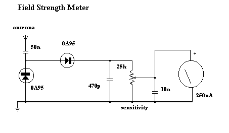
Not knowing much about RF, but whats the 50nF cap for? Ive seen values elsewhere in the pf range
OK So thats really cool. I can see the actual signal being sent out on my scope 😄
primal warren
The 50nF capacitor just acts as a DC block for a voltage shifter/doubler. Its value is not at all critical.
wraith panther
So testing is finished. I did not do long range testing as Im pretty confident theese would be OK. Updated my thread.
wraith panther
Huh, the bot stops me from uploading the code I used.
primal warren
Code tends to have character patterns that look a lot like problems, I think the usual advice is to use a service like pastebin
wraith panther
Its simple enough lol. I mean, its just using the equivalent command to send out ASCII characters via serial.
 grizzled vapor
wraith panther
Not knowing much about RF, but whats the 50nF cap for? Ive seen values elsewhere...
grizzled vapor
wraith panther
Not knowing much about RF, but whats the 50nF cap for? Ive seen values elsewhere...
You probably want a bigger capacitor with low inductance is all you need so it can pass high frequencies. I don't know rf either, so I'm just making a very educated guess.
 primal jolt
im having a very hard time connecting a nano every to an RFM69HCW (radio) using the RadioHead library, particularly it doesnt seem to recognize that theres even a device on the SPI interface
granite spear
primal jolt
im having a very hard time connecting a nano every to an RFM69HCW (radio) using ...
The first thing I would double-check would be the pin assignments you're using.
primal jolt
what are the spi pins on a nano every? i couldnt find much info on that
granite spear
Looks like D11 (MOSI), D12 (MISO), and D13 (SCK).
primal jolt
which pins should those connect to on the radio chip?
granite spear
Aren't the radio pins labeled as MOSI, etc.?
primal jolt
yes, but im not great at this
primal jolt
nvm, im just dumb
 wraith panther
Lol so I have a problem:

👀 I bought more modules than I need-because I didnt know if this seller on Aliexpress would get them to me, so now I have other modules to test. Guess its not a bad problem to have but, its not like Im going to use a bunch of wireless devices around the house lol
 dark tiger
I see no problem, I see a hobby
timid onyx
anyone know of a decent z-wave 700 breakout?
thread is around the corner but still using 2.4GHz so i'd prefer to use z-wave
 haughty patrol
Anyone know where to get, or build a 2m transceiver? I'm a licenesed ham, and want to build my own aprs weather station.
primal warren
Getting them isn't too tough, hamfests, surplus places, and ham radio stores like Ham Radio Outlet carry them. There are also the popular inexpensive radios like the ones made by Baofeng. There are also a variety of designs and kits by various radio clubs that can be instructive and satisfying to build.
haughty patrol
I guess I need to find those kits, cuz I didn't want a baofeng in a box hooked to a raspberry pi, it just feels really silly, I don't understand why all the ham stuff I find is like prebuilt radios.
Not when all other forms of radios out there I can buy chips and have.
primal warren
There are also some nice RX/TX modules by Dorji, NiceRF, Sunrise, etc, and some Arduino type shields (HamShield, ArduTrx, etc.) built around them
Some kit pointers here, but most of the kits I see are for HF, as VHF and UHF require special parts and techniques, so the designs are complicated and subtle and require somewhat exotic parts. No problem for manufacturers cranking out thousands of units, but hard to justify for building a kit you might sell a few dozen of.

Ham Radio Secrets
Ham radio kits pack a lot of value. This page explains how much and why.
haughty patrol
primal warren
https://www.hamradiosecrets.com/ham-radio-kits.html
Ahhh that's some information I didn't have that makes some things make more sense.
primal warren
If you don't mind using the prebuilt modules as the heart of a transceiver, some useful part numbers to look for are the Dorji DRA818V, NiceRF SA818-V, and Sunrise SR_FRS_1WV
haughty patrol
I'm not really involved in the local club cuz I haven't bothered, and I can't ever seem to get a word in edgewize with the old men on the repeaters so I'm kinda just out here in ham world googling with no one to talk to.
primal warren
That's frustrating. There are several hams on this Discord, and we're happy to answer questions and help out how we can
haughty patrol
primal warren
If you don't mind using the prebuilt modules as the heart of a transceiver, some...
OMG those are some of the things I've been googling for for months with no luck.
Thank you!
primal warren
That's the result of me chasing a bunch of things down for a while, so I'm happy to share the results of my efforts
Most of the modules are based on the same chip (Auctus AT1846S or a clone), along with an RF amplifier of some sort, some switching logic, and antenna matching circuitry
Oh, I found a breakout board that could be handy http://hamshop.cz/rf-modules-c36/pcb-for-dorji-dra818v-or-dra818u-modules-i271/

Not much to it, but it looks really handy
 haughty patrol
looks handy, now just to figure out how to order one of the chips LOL
primal warren
It looks like a couple of them are available on Tindie for good prices
wraith panther
Aliexpress has them too if you dont mind the month wait
primal warren
wraith panther
🤔 they have other RF modules lol
primal warren
Yeah, there are a variety to choose from, I figured I'd just give a couple of examples I'd happened to see
 molten torrent
I'm using a bunch of nRF24L01s for my class to control simple electronics on a robot. We have the radios connected to Arduino running the RF24 library by TMRh20. (See here for the circuit and some example programs: https://github.com/michaelshiloh/resourcesForClasses/tree/master/src/arduinoSketches/nRF24L01). We have perhaps 7 pairs of these working at a time. Each pair has a different address so they should not be interfering with each other's data, although obviously they are competing for bandwidth.
We're having lots of problems with the radio link randomly dropping out completely, or receiving incorrect data.
Do you have any suggestions as to what might be causing this, and more importantly, what I might do to overcome these problems?
little forge
I know there is a way to set the ble Device name to something clear so I know what device to select when trying to use the ble connect app to control my playground bluetooth but I can't find this info anywhere maybe I'm just not seeing it because i'm to tired to be doing this at the moment currently the code for my project is unchanged from the example code from https://learn.adafruit.com/bluetooth-turtle-bot-with-circuitpython-and-crickit/code-with-circuitpython. I think name I want will be play-ble I have tried a few different things like ble.name = "play-BLE" no luck Please san someone help me
 exotic compass
 primal warren
molten torrent
Do you have any suggestions as to what might be causing this, and more important...
primal warren
molten torrent
Do you have any suggestions as to what might be causing this, and more important...
I think those chips are using a spread spectrum modulation that hops around between different frequencies in a known pattern, both to dodge interference from other devices and reduce interference they produce. The problem you're seeing could be that they're all using the same modulation pattern so instead of dodging each other, they're all stepping on each other. What I don't know is how (or if) you can change the modulation pattern using that particular library.
primal warren
little forge
I know there is a way to set the ble Device name to something clear so I know w...
Bluetooth is complicated, so I'm mostly guessing here. I think setting ble.name just sets what is returned after the connection is made. In order to set the name that's selected before you connect, I think you need to create and configure an Advertisement object (which you can import from adafruit_ble.advertising). Then set the short_name property of that object to the one you want, and hand that advertisement object to ble.start_advertising()
molten torrent
primal warren
I think those chips are using a spread spectrum modulation that hops around betw...
Thanks for the insight. I'll study the documentation and see if there's a way to manipulate that.
 stoic glen
I m using a bunch of nRF24L01s for my
 misty sleet
I'm trying to play audio from a microcontroller over the radio using Adafruit's Si4713 breakout board. The transmitter works when I play audio from my computer, and the microcontroller plays audio when I hook it up to a speaker, but for whatever reason it doesn't work when I connect the microcontroller's audio output to the transmitter's input. Any idea what I'm doing wrong?
primal warren
misty sleet
I'm trying to play audio from a microcontroller over the radio using Adafruit's ...
Three possibilities occur to me. The first one is that the transmitter is coupling RF into the data leads and scrambling the signal (I had the same issue when trying to build a UHF remote control once: the data wiring acted as antennæ and picked up the transmission). The second is a ground problem, where the units don't share a common zero-volt reference for some reason (floating power supply, ground loop, etc.). The third is a power supply problem: it could be the power draw of the transmitter is dragging down the power supply to the microcontroller.
misty sleet
primal warren
Three possibilities occur to me. The first one is that the transmitter is coupl...
The microcontroller and the transmitter have a common ground, and the microcontroller is doing another task at the same time, which seems to be functioning, so I don't think it's a power or grounding issue.
I have noticed that my radio makes a slightly different sound depending on which way I wiggle the wires, so it could be the first issue you mentioned. How would I go about fixing this?
A few other things I should mention: When the circuit is off and my radio is tuned to the station, I hear static, whereas when the circuit is on, I hear nothing, so the transmitter must be doing something. In some cases I can hear the audio from the radio very faintly but with a lot of static and a screeching sound.
primal warren
misty sleet
The microcontroller and the transmitter have a common ground, and the microcontr...
You can try using shielded or twisted pair cable, or simply adjusting the length or arrangement of the wires
restive fjord
Hello everyone, I am looking for example code (circuitpython or micropython) the subject of receiving BLE beacons with an nRF24L01 module. who can help?
 sterile tundra
restive fjord
Hello everyone, I am looking for example code (circuitpython or micropython) the...
sterile tundra
restive fjord
Hello everyone, I am looking for example code (circuitpython or micropython) the...
Just to make sure I’m understanding this right, is the communication Beacon -> nRF24L01?
restive fjord
sterile tundra
Just to make sure I’m understanding this right, is the communication Beacon -> n...
https://www.youtube.com/watch?v=BejQ1GyEmWU - this is what i want to do but using circuitpython on esp32s2 with no bluetooth build in

Xiaomi BLE Temperature and Humidity monitor datalogger
with Arduino, nRF24L01, RTC and N5110 LCD
Changes in BLE version:
- no longer LowPower (BLE data need to be received all the time)
- less RAM usage - only 36 bytes are used for N5110 LCD frame buffer (844 previously)
- saved some 9x14 font flash used clock, now font is reduced to digit...
sterile tundra
restive fjord
https://www.youtube.com/watch?v=BejQ1GyEmWU - this is what i want to do but usin...
What libraries are you using for the nRF24?
sterile tundra
sterile tundra
What libraries are you using for the nRF24?
I found what seems to be the go-to circuit Python library for the nRF24. When I look at the BLE API for the library though, it seems to indicate the nRF24 has some limitations for BLE support. In addition, the library only supports broadcasting Beacon packets. There’s no support in the library for receiving Beacon packets. It might make sense to look into a different module for Bluetooth support. Here’s the page that explains the Bluetooth library and it’s limitations. https://circuitpython-nrf24l01.readthedocs.io/en/latest/core_api/ble_api.html
 gilded isle
hello community , i want to make a lora based network . i want to ask if someone know how destination and node function work in adafruit_rfm9x library , because i need to set source and destination addresses for my communication
in my scenario a drone talks to a base
and this base talk to a server via lora
all communication is based to lora
granite spear
gilded isle
hello community , i want to make a lora based network . i want to ask if someone...
The base level LoRa protocols doesn't include any addressing scheme (every node on the channel receives every packet), so you'd either want to implement that yourself as part of the data packet, or use a higher-level protocol like LoRaWAN.
restive fjord
https://tapr.org/ was a good resource for ax.25
normal drift
gilded isle
hello community , i want to make a lora based network . i want to ask if someone...
If you are using the CircuitPython adafruit_rfm9x library, it supports the same header used for the Arduino RadioHead library. You can specify addresses with this. There are examples here: https://github.com/adafruit/Adafruit_CircuitPython_RFM9x/tree/main/examples take a look at the rfm9x_node1.py and rfm9x_node2.py examples.
 deft lion
Is there BLE support in CircuitPython for Adafruit ESP32 Feather V2? Or, is it coming in the future?
slender current
@deft lion There is a PR to enable it for some ESP32s. Note that it's still partial support like the S3 has.
 grim dove
Does the https://www.adafruit.com/product/3072 do encryption and auto-retransmit or just the non-Lora RFM69's

"You see, wire telegraph is a kind of a very, very long cat. You pull his tail in New York and his head is meowing in Los Angeles. Do you understand this? And radio operates ...
normal drift
grim dove
Does the https://www.adafruit.com/product/3072 do encryption and auto-retransmit...
They are implemented in software. Are you using Arduino or Circuitpython? I think the Arduino RadioHead library does support encryption for the RFM9x. CircuitPython library does not. Both will support auto-retransmit -- it is referred to as "reliable datagram" in the RadioHead Library and the same protocol is implemented in the CircuitPython library. I hope that helps.
FYI -- here is an example of using encryption with the Arduino RadioHead library https://www.airspayce.com/mikem/arduino/RadioHead/rf95_encrypted_client_8pde-example.html
I have not tried it myself...
 sweet jungle
Hello Folks. I have several Adafruit Feather 32u4 RFM95 LoRa "radiofruits" that I stack on Feather M4s for a variety of applications (weather station, IR animal camera, telegraph, etc.). Normally when I am testing these modules I can get -20 dB or better received signal power when I set the Tx within a few feet of the Rx (normally using spring antennas). I always run at max power setting (tx_power = 23). Lately, though, I can do no better than -50 to -60 dB with the same setup/configuration. One possible difference is that I am running with CircuitPython 7.3.3 on the M4s. Previously I think that I was running with CircuitPython 6.x. I have done some tests where I have tweaked the tx_power) down to 13 (default), but it does not change the RSSI. Any suggestions as to what might be causing my low RSSI? Thanks!
 main girder
is this the better place to ask about FONA stuff rather than #help-with-circuitpython
because I'm decently sure it's a software issue
see here #1050380383188951040
 round acorn
Hello! I'm using ESP32 RFM95W module to send data over LoraWAN. I'm using the latest version mcci-catena/arduino-lmic library. Although it works well, I'm unable to effectively set ADR or change SF. There are several issue of this type on github, but they are very old and apparently are already fixed. So, I don't know anyone here has faced similar issue and could help me please
round acorn
It's always working at SF7BW125
round acorn
Okey, so if anyone if interested on this, I found that the first uplink SF can not be changed. My ESP32 was deep sleeping after the first uplink, and as it reset itself after the deep sleep every uplink was the first one...
woeful vector
Hi all
Anyone worked with SIm800L for HTTP post ?
primal warren
woeful vector
Hi all
Anyone worked with SIm800L for HTTP post ?
I've used the SIM808 for that, but you're probably better off asking your actual question than whether someone has "worked with" it.
sweet jungle
Weak RFM95 LoRa Signal Power
 fringe isle
Hi I have a question. I have a lora node (925Mhz) that placed under concrete box with metal plat on top. I know the best option for optimal RF transmission would be to place the antena outside the box. But if I made cut holes for vent would the signal penetrate, so I can mount the antena next to the metal plate? If yes how big the hole aperture/diameter so the 925Mhz can pass?
restive fjord
I'd be very suspicious that a metal plate improves signal transmission (or reception).
Normally I'd just say don't do it.
I usually reframe questions as if the device had 'wants' and that I had no wants. That's the right view, I think. (I know it is there but it does not 'know' that I am there ;)
primal warren
fringe isle
Hi I have a question. I have a lora node (925Mhz) that placed under concrete box...
10cm would be large enough that 925MHz wouldn't be greatly attenuated
fringe isle
Thank you for the answers
fringe isle
primal warren
10cm would be large enough that 925MHz wouldn't be greatly attenuated
Could you tell me how you come up with that number?
restive fjord
468 / f = y
https://www.radioqth.net/dipole
A 1/2 wave dipole (antenna) for 27 MHz is about 17 feet long.
 $ dc -e '5 k 468 27 / p q'
17.33333 # feet
 $ dc -e '5 k 468 925 / p q'
.50594 # feet
The problem is equivalent to a "waveguide beyond cutoff", so I just used this calculator https://www.everythingrf.com/rf-calculators/circular-waveguide-calculator
 stuck portal
Can a LoRa Radio transmit and receive audio?
granite spear
stuck portal
Can a LoRa Radio transmit and receive audio?
Not natively. If you compress it enough, you could send audio data over a LoRa link, but it's something that you'd have to implement as a custom protocol.
 umbral oxide
packets are only 252 bytes
stuck portal
Ok. I'll make something at some point. Thanks.
 edgy swift
I have run into a problem that is perfect for the NRF52840. I have several of the feather express boards, but I am struggling with the basics in Mu/CircuitPython I just need to transmit audio from several sources to a Pi and record the data via a python program. The demo programs (most up-to-date) to BlueFruit connect don't actually connect. Can anyone point me to an example, or should I drop back to Arduino IDE for more success?
 young cove
edgy swift
I have run into a problem that is perfect for the NRF52840. I have several of t...
young cove
edgy swift
I have run into a problem that is perfect for the NRF52840. I have several of t...
Have you tried the CircuitPython 8.0.0-betas? A few bugs were fixed, though the basic demos should work with 7.3.3. Plenty of people have success with this.
Transmitting a lot of audio over BLE could be an issue. Are these short chunks?
CircuitPython BLE on the Pi requires using the bleak library under the covers. There have been problems in the past with the Bluetooth firmware on the Pi, though that was while ago.
Further questions are probably better asked in #help-with-circuitpython to get more eyes on the problems
stuck portal
Using Arduino IDE, can LoRa transmit and/or receive audio?
primal warren
As discussed above, LoRa probably doesn't have the bandwidth to do so effectively.
 wary arrow
Is there a chip anyone could recommend for combined ADC + FFT around 10MHz?
half plover
wary arrow
Is there a chip anyone could recommend for combined ADC + FFT around 10MHz?
How deep and precise of a sample do you want
Do you want like 8 bit ADC? 10 bit? 12? 16? You’ll want to use a SPI interface for speed. Though usually high speed Analog front ends feed into an FPGA for really high speed FFT.
If you took something like this: https://www.digikey.com/en/products/detail/analog-devices-inc/AD9283BRSZ-50/621671 and used PIO on an RP2040 in Arduino, you could probably get really close to 10MHz
The ADC uses a parallel interface which would either be piped to an fpga or pio input that could sample all the input pins synchronously
primal warren
wary arrow
Is there a chip anyone could recommend for combined ADC + FFT around 10MHz?
How much bandwidth do you need? Is it like 0 to 10MHz, or maybe 9.5MHz - 10MHz? Many units use a heterodyne technique where the incoming signal is mixed with another frequency to produce a lower frequency result that's easier to process.
wary arrow
primal warren
How much bandwidth do you need? Is it like 0 to 10MHz, or maybe 9.5MHz - 10MHz?...
Thank you, I didn’t know about this. Bandwidth is 5-15MHz ish
wary arrow
half plover
If you took something like this: https://www.digikey.com/en/products/detail/anal...
Thanks!!
 untold needle
Need to make a radio receiver for frequencies from 10-40MHz and need the data to store somewhere on the circuit to be analysed later. I have been advised to look at heterodyne receivers. I was wondering how to make this in MHz rather than what most people's projects frequencies are, which is usually in KHz. I was wondering if this would make a difference that I would need to account for.
granite spear
untold needle
Need to make a radio receiver for frequencies from 10-40MHz and need the data to...
One obvious difference is the amount of data you'll need to digitize and store. That'll need a high-speed ADC and a lot of RAM, depending on how long you need to record the signal.
untold needle
granite spear
One obvious difference is the amount of data you'll need to digitize and store. ...
right, but circuitry-wise, what components would have to be different as well and is there anywhere I can simulate this. I have an oscillator for those frequencies and an amplifier, do I need a mixer or anything else. Or can I just follow what most people have done for their AM/FM radio receivers.
granite spear
untold needle
right, but circuitry-wise, what components would have to be different as well an...
Sorry, I don't have that kind of experience to advise you on. Digital guy... 😅
untold needle
granite spear
Sorry, I don't have that kind of experience to advise you on. Digital guy... 😅
no problem, thanks though
primal warren
The differences between kilohertz and megahertz are mostly component values and construction techniques, the basic principles are largely the same.
You will need a mixer if you want to employ a heterodyne technique. There are other approaches, of course, but I'd recommend the heterodyne one as, while it sounds complicated, makes the circuitry simpler to build and more modular.
untold needle
right, how do I calculate these different component values
untold needle
primal warren
You will need a mixer if you want to employ a heterodyne technique. There are o...
Yes I think I will go with it
Will I need a high speed ADC chip as EdKeyes recommended or is there any other way to do it(I'm also thinking about the weight here since my restriction is 300g)
primal warren
Most things scale linearly with frequency, so as the frequency goes up, you'll see smaller values for capacitance and inductance. You can play with values and frequencies with this simple calculator to get a feel for how it works. https://www.allaboutcircuits.com/tools/tank-circuit-resonance-calculator/
granite spear
BTW, the high-speed ADC would depend on the bandwidth of the signal you're recording. I was originally assuming you wanted to capture a good chunk of the 10-40MHz spectrum, but if you're just tuning into a narrow channel within that range to listen for some specific lower-speed data, you can digitize at baseband instead, and the ADC could be more modest.
restive fjord
The old problem with building a superhet from scratch was oscillator stability.
For that reason it was not considered a beginner's project at all.
621.384 is the call-number that's useful (in the lending library)
untold needle
restive fjord
The old problem with building a superhet from scratch was oscillator stability.
...
I'm definitely a beginner
however
I do have a book on superhets
untold needle
granite spear
BTW, the high-speed ADC would depend on the bandwidth of the signal you're recor...
Well mainly frequencies from 20-30MHz
restive fjord
I would wild-guess that you can get a stable oscillator today and interface it successfully in a modular build, but I've never done it. ;)
For some reason or another the theory behind receivers is something I iterate through quite often whenever I'm working with the technology (using a transciever to converse on the air, or just listening passively).
restive fjord
You can hold a second inexpensive shortwave radio very close to the one you're listening to and decode SSB on an AM-only radio for example. ;)
Or CW.
untold needle
restive fjord
You can hold a second inexpensive shortwave radio very close to the one you're l...
hmmmm, I guess I'm definitely going to have to go down the rabbit hole of churning through material
Building my own radio receiver that is not AM or FM is going to be tought
tought
tough
restive fjord
I'd ordinarily recommend an inexpensive vacuum-tube based receiver but getting one in working condition isn't easy, anymore. ;)
untold needle
Right
restive fjord
AM is almost 'trivial' but FM is not. Today with all 'the chips' yea it is likely to be easier.
untold needle
restive fjord
AM is almost 'trivial' but FM is not. Today with all 'the chips' yea it is likel...
well 20-40MHz probably isn't trivial
especially seeing as I have to create a receiver that can store the data under 300g
restive fjord
I've heard of this project type before (wx balloon) (radiosonde) but never once has someone (much) later came back with an 'I DID IT' report (pity if they had and I'm just not remembering it. ;)
My brief look into it said 'get a radiosonde if you want a radiosonde' as they've already solved the problems.
untold needle
restive fjord
I've heard of this project type before (wx balloon) (radiosonde) but never once ...
this is very similar to my project but mine needs to operate at 20-40MHz
restive fjord
The nice thing about the upper end of that is the length of the radiating element of the antenna .. gets shorter. CB (27 MHz) is about 17 feet for a 1/2 wave dipole (L = 468/f?)
untold needle
restive fjord
The nice thing about the upper end of that is the length of the radiating elemen...
I dont even know to start with the heterodyne
I have an oscillator
and capacitors
but I dont know what values I need for my components and I dont know how to connect them
restive fjord
signal comes into the antenna. it goes into one leg of the mixer. a local oscillator is also injected into the mixer.
untold needle
restive fjord
signal comes into the antenna. it goes into one leg of the mixer. a local osci...
right
but how do I store this data
restive fjord
it's not data
untold needle
restive fjord
it's not data
What is it then? after its in the mixer
restive fjord
you get the four products of the mixer (sum difference freq a freq b) out of the mixer.
untold needle
because ideally I would like to graph the frequencies Im receiving
untold needle
restive fjord
you get the four products of the mixer (sum difference freq a freq b) out of the...
right
restive fjord
It's still a signal you've just moved the carrier frequency
untold needle
right
but can the mixer store different frequencies or just the first one that hits it
restive fjord
Signals consist of modulation and carrier (For basic signals)
untold needle
yes
restive fjord
The modulation has the information (intelligence) except for CW transmissions (morse code) where the modulation is simply the presence of absence of the carrier.
granite spear
Maybe back up a second. Do you know what transmitter is being used to send whatever signals you're trying to pick up?
untold needle
the project is to emit radio waves to bounce back off the ionosphere then receive them in my weather balloon
untold needle
granite spear
Maybe back up a second. Do you know what transmitter is being used to send whate...
I do
granite spear
So what does the transmitted signal look like? It is just a carrier, is it Morse code, is it video?
untold needle
a carrier
but for it to reflect off the ionosphere
it has to be between 1 and 40MHz
We are only planning to do 3 or 4 specific frequencies
like 21, 28, 32 and 36MH
granite spear
Gotcha. This starts to be easier, then, since your receiver just needs to detect the strength of the signal at a particular frequency, rather than try to decode any actual data, etc.
untold needle
granite spear
Gotcha. This starts to be easier, then, since your receiver just needs to detect...
yes
exactly that
remote pond
untold needle
but for it to reflect off the ionosphere
so something like ionospheric radar?
untold needle
remote pond
so something like ionospheric radar?
I guess so yes
its quite simple
send a carrier
it reflects
that hits my weather balloon
and I want it to basically just store the frequency received and the strength
untold needle
granite spear
Gotcha. This starts to be easier, then, since your receiver just needs to detect...
That sums it up basically perfectly yes
remote pond
untold needle
and I want it to basically just store the frequency received and the strength
you might want to modulate the transmitted signal somewhat, to reduce noise. do you need to get the time of flight?
untold needle
remote pond
you might want to modulate the transmitted signal somewhat, to reduce noise. do ...
time of flight?
remote pond
untold needle
time of flight?
like do you want to figure out how far away the reflection is?
granite spear
It'll likely be easiest if you somewhat hard-code the frequencies you're actually using rather than getting a general "show all the frequencies" spectrogram. So you can feed the signal into specific filters, or switch your oscillator frequency to tune into the right channel.
untold needle
granite spear
It'll likely be easiest if you somewhat hard-code the frequencies you're actuall...
thats the plan
do i need fourier
granite spear
No, you shouldn't need Fourier, just a filter circuit or few. I'm not an expert, so I'll defer to other people here who are, but my mental model would be like antenna -> mixer -> filter -> amplitude detection -> low-speed ADC -> store the data.
untold needle
the hard code frequencies will be 27MHz, 27.5 and 28MHz
since we have an oscillator for 27-28MHz
These our our components:
ADE-1 RF Mixer
TL051 IF amplifier
MAV11 amplifier
AD8307 log detector
so I have 2 amplifiers, a mixer and a log detector @granite spear
and an oscillator for 27-28MHz
granite spear
Great, the AD8307 is the "amplitude detection" part I was fuzzy about. That'll give you a good signal strength measurement.
untold needle
granite spear
Great, the AD8307 is the "amplitude detection" part I was fuzzy about. That'll g...
write but couldn't we store the signal as analogue rather than using an ADC, what are the benefits of an ADCA
ADC
granite spear
"Store" usually implies saving it on an SD Card or something digital. To store it as analog you'd need like a tape recorder or something like that.
untold needle
right yes yes yes
untold needle
granite spear
"Store" usually implies saving it on an SD Card or something digital. To store i...
how do I save it on an SD card without programming it
does it just automatically go from the AD8307 to the SD
but if we alter the frequency we transmit on the ground, we might not be able to change the oscillator's frequency in-flight, we have 3 hard coded frequencies to transmit, 27, 27.5 and 28, so will the oscillator still work
remote pond
untold needle
does it just automatically go from the AD8307 to the SD
probably not. you need to read the analog output from the AD8307 with the ADC of an MCU or something, and write that out to the SD card
untold needle
remote pond
probably not. you need to read the analog output from the AD8307 with the ADC of...
Right, understood
granite spear
"Oh my sweet summer child..." Nothing in electronics is automatic. You have to force the circuit to perform your will through design and programming and blood and sweat and tears... 😉
untold needle
granite spear
"Oh my sweet summer child..." Nothing in electronics is automatic. You have to *...
Hahahaha
but apart from saving it to SD
remote pond
granite spear
"Oh my sweet summer child..." Nothing in electronics is automatic. You have to *...
except maybe for the kinds of circuits with hidden feedback that makes them look like magic
untold needle
the rest seems pretty simple, or am I missing something
antenna -> mixer -> filter -> amplitude detection -> low-speed ADC -> store the data.
this doesn't seem so hard
will this definitely work? It seems way too good to be true haha.
remote pond
so your (variable-frequency) transmitter is on the ground, and your receiver is on the balloon?
untold needle
remote pond
so your (variable-frequency) transmitter is on the ground, and your receiver is ...
yes
we are only planning to transmit 3 frequencies
27, 27.5 and 28MHz
granite spear
untold needle
will this definitely work? It seems way too good to be true haha.
There's definitely a lot of details to get right in the process, but as radio projects go, it's not too bad.
untold needle
granite spear
There's definitely a lot of details to get right in the process, but as radio pr...
yeah......
how fast can we log something to an SD card though?
remote pond
i guess you could hop the LO among those frequencies, if you can tolerate discontinuous reception and don't want to have a communication channel to ask the receiver to switch frequencies
untold needle
remote pond
i guess you could hop the LO among those frequencies, if you can tolerate discon...
mmmm, what about 3 different oscillators for the 3 different frequencies, I'd prefer a graph
well my group would
because depending on how fast we can store it, it affects the amount of samples. Therefore 27MHz could look closer to 27.5MHz with too few samples couldn't it?
granite spear
untold needle
how fast can we log something to an SD card though?
Pretty fast, at least 1000 measurements/sec without too much trouble. You probably wouldn't need anything like that.
remote pond
you want to sample all 3 frequencies simultaneously?
untold needle
remote pond
you want to sample all 3 frequencies simultaneously?
no
different time points
so like 5 minutes of 27
5 minutes of 27.5
5 minutes of 28
untold needle
granite spear
Pretty fast, at least 1000 measurements/sec without too much trouble. You probab...
my friend in my group says you need at least 300,000 a second to reliable discern signals in the 10s of MHz? Is he mistaken
remote pond
untold needle
my friend in my group says you need at least 300,000 a second to reliable discer...
i think that really needs more context to give a reasonable answer
untold needle
he first said, 'samples just means data points - the more data points we can take per second, the more accurate our reading is (27MHz will look like 27.5MHz with too few samples)'
then said we need 0.3MHz of measurements
remote pond
you can send a 1kHz bandwidth signal on a 27MHz carrier, and you'd still only need 1kHz of bandwidth to sample the demodulated signal
untold needle
I think he must be mistaken
remote pond
untold needle
he first said, 'samples just means data points - the more data points we can tak...
could you ask him to explain what he means by "27MHz will look like 27.5MHz with too few samples"?
granite spear
untold needle
then said we need 0.3MHz of measurements
In this case your oscillator tuning and your filters would be what distinguishes the frequencies from each other, so you don't have to sample fast to tell them apart.
remote pond
your transmitter is sending unmodulated carriers at those three frequencies, one at a time, right?
untold needle
granite spear
In this case your oscillator tuning and your filters would be what distinguishes...
300,000 measurements/secright right
we don't want to send information on a carrier signal like FM/AM radio does, we want the carrier signal itself basically
remote pond
do you expect nonlinear behavior? that might be the source of some of the concern
untold needle
remote pond
do you expect nonlinear behavior? that might be the source of some of the concer...
thanks a lot
untold needle
granite spear
In this case your oscillator tuning and your filters would be what distinguishes...
right so specific band-pass filters for each frequency of course
untold needle
remote pond
your transmitter is sending unmodulated carriers at those three frequencies, one...
yes, exactly that
I dont think we expect nonlinear behaviour, should we?
remote pond
if you wanted to measure them simultaneously, you'd need a mixer with more than 1MHz bandwidth, and then digitize the demodulated signal (tricky), or feed it into three narrowband filters, one for each possible transmission frequency, and sample those
untold needle
remote pond
if you wanted to measure them simultaneously, you'd need a mixer with more than ...
nah thankfully not, they are one at a time
remote pond
untold needle
I dont think we expect nonlinear behaviour, should we?
i dunno. the ionosphere does weird things sometimes
untold needle
remote pond
i dunno. the ionosphere does weird things sometimes
this is very true
So far this seems quite...easy, I say that hesitantly because lots could still go wrong and we are all beginners in our team but your advice and EdKeyes seems great.
primal warren
untold needle
because ideally I would like to graph the frequencies Im receiving
That is a whole different kettle of fish, known as a "spectrum analyzer"
untold needle
primal warren
That is a whole different kettle of fish, known as a "spectrum analyzer"
well thats ideal, just knowing frequency and strength would suffice
but if it isnt much harder or impossible
a spectrum analyzer would be nice
since we do have to present our data
at the end of the project
primal warren
untold needle
We are only planning to do 3 or 4 specific frequencies
That, on the other hand, is a much easier proposition and you may not even need a heterodyne circuit, since you'd basically just looking for the presence or absence of a signal, and don't need to decode modulation. You might be able to do that with a set of tuned circuits/filters, one for each frequency you want to detect.
untold needle
primal warren
That, on the other hand, is a much easier proposition and you may not even need ...
thats the plan now, thanks to you and several others clearing it up
primal warren
Yeah, the more details we know, the more specific answers we can offer
untold needle
primal warren
Yeah, the more details we know, the more specific answers we can offer
you guys are great at this problem solving
must have loads of experience
untold needle
primal warren
Yeah, the more details we know, the more specific answers we can offer
the last problem I'm having is with the antenna
using my research, it says optimum length of an antenna is quarter wavelength
that would mean we need a 10m+ antenna
how would that work out
granite spear
You should be able to get a more compact one using a helical coil or something similar. There are lots of off-the-shelf options in the 27MHz band you can look at.
primal warren
If it's on a a balloon, you can just have a thin wire hanging down.
untold needle
granite spear
You should be able to get a more compact one using a helical coil or something s...
Cant find anything like it
I cant find anything lightweight(<200g) that receives 27MHz
untold needle
primal warren
If it's on a a balloon, you can just have a thin wire hanging down.
How long would this have to be?
primal warren
A quick search for "antenna wavelength calculator" yields a bunch of hits including this one https://www.southwestantennas.com/calculator/antenna-wavelength which says 277cm for 27MHz. I have seen balloon transmitters tailing J-pole antennæ but a simple quarter wave one seems lighter and easier.
granite spear
untold needle
I cant find anything lightweight(<200g) that receives 27MHz
This claims to be 150g... a lighter-weight "tactical" antenna. https://www.amazon.com/ABBREE-Tactical-42-5-Inch-Connector-Compatible/dp/B07VF563FB

ABBREE Tactical Antenna 27Mhz 42.5-Inch for CB Handheld/Portable Radio with BNC Connector Compatible with Cobra Midland Uniden Anytone CB Radio
primal warren
It's just a simple quarter wave wire, just a piece of wire would be lighter and cheaper and work as well.
untold needle
primal warren
A quick search for "antenna wavelength calculator" yields a bunch of hits includ...
hmmmm
remote pond
you could use a magnetic antenna, but the receive signal strength calibration might be trickier with those
granite spear
But I think madbodger probably has the best solution. In most terrestrial applications the antenna needs some structure to stand up vertical, but for a balloon, you can have a wire just hanging down, which could be very light.
untold needle
granite spear
But I think madbodger probably has the best solution. In most terrestrial applic...
riht
right
but how to connect that to my circuit
granite spear
...mumble mumble matching-network circuit mumble mumble RF black magic mumble mumble...
untold needle
https://www.sotabeams.co.uk/antenna-wire-lightweight-100m/ quickly I found this and its only 3.3g per metre, so 3 metres is 10g

SOTABEAMS
Find great deals on SOTABEAMS for Antenna Wire - Lightweight - 100m. Shop HF and VHF Portable Antennas and Accessories for Amateur Radio/Ham Radio with confidence.
but to connect that to my circuit
I dont know
untold needle
granite spear
...mumble mumble matching-network circuit mumble mumble RF black magic mumble mu...
Black magic
untold needle
primal warren
It's just a simple quarter wave wire, just a piece of wire would be lighter and ...
I agree but I don't know how I would connect that to my circuit
granite spear
To a first approximation, the antenna wire is just where the radio signal enters your circuit, so the wire connection itself would be an input to your receiver/amplifier/mixer. However, there might need to be a little bit of impedance-matching "stuff" or the like involved. <hand-wave>
untold needle
yes
the wire connection is just where the radio wave hits it
but I dont know how to connect that to my other components
I will research
remote pond
yeah, you probably need an impedance matching network to connect the antenna to your circuit's input. i think often it's a simple hand-wound transformer on a toroid? your RF mixer probably has specs on what impedance it needs to see on its ports
primal warren
untold needle
https://www.roadtechmarine.com.au/3-foot-27mhz-helical-whip/p/DC2030
Are you in Australia? Did you know about this balloon project done by a student there? https://diyodemag.com/features/new_heights_part_1_high_altitude_weather_balloon_artemis_global_tracker
primal warren
untold needle
I dont know
The impedance of a quarter wave antenna at its feed point is about 36Ω, and most radio gear is designed to operate into a 50Ω load. Since it's a receiver, not a transmitter, that impedance mismatch (which isn't too bad anyway) wouldn't cause a problem.
untold needle
primal warren
The impedance of a quarter wave antenna at its feed point is about 36Ω, and most...
my teammate seems to think I need fourier analysis to find out the exact frequency of the incoming wave from the antenna, without using fourier, how would I find out the EXACT frequency of the incoming wave
@granite spear if you can help with this that would be much appreciated
granite spear
untold needle
my teammate seems to think I need fourier analysis to find out the exact frequen...
As I understand your goal, you don't need to precisely measure an unknown frequency, but only need to measure the signal strength at certain known frequencies. So your filters will already zero in to say "Give me only the radio signals between 26.9 and 27.1 MHz", and then you'd have the amplitude of everything in that band, which would encompass your source signal.
It would be more complicated if you needed to measure the frequencies themselves, and in that case you would need something like Fourier analysis, but I don't think you need to do that as you've described the problem.
If you're worried about confusing the signal-strength measurements with background radio noise, then you may want to consider doing some slow modulation of your transmitter, like turning it on and off every second. That way the receiver data logs would show an obvious pattern in the signal strength, and you can distinguish between your transmitter's impact versus background noise.
remote pond
untold needle
my teammate seems to think I need fourier analysis to find out the exact frequen...
could you describe at a higher level the experiment you're going to be doing with this equipment? that might help narrow down the solutions
remote pond
untold needle
my teammate seems to think I need fourier analysis to find out the exact frequen...
asking your teammate why knowing the exact frequency is important might be helpful, if the transmitter will only be one of three fixed frequencies. also, there's no such thing as "exact frequency" in practice. any measurement of frequency will have sources of error, and finite Fourier transforms will trade off frequency resolution vs time resolution
also, if your three fixed transmitter frequencies span 1MHz (which i think is true based on previous postings), you will need to sample the mixer output at more than 2MHz (Nyquist limit) for your FFT, which could be challenging on a microcontroller
half plover
remote pond
also, if your three fixed transmitter frequencies span 1MHz (which i think is tr...
Getting into fpga territory
Or, at the very least. PIO territory
remote pond
PIO is digital only right?
granite spear
I believe so, yeah. It's not impossible that the ADC is also hooked up to the PIO state machine, but I haven't run across anyone using it like that.
remote pond
a parallel-output ADC might be one such situation
remote pond
but 2MHz ADCs seem likely to be on the expensive side
half plover
$10 for a 50MHz 8Bit ADC parallel out
remote pond
nice
remote pond
wow this stuff got a lot cheaper since the last time i looked at parts in this space
untold needle
remote pond
also, if your three fixed transmitter frequencies span 1MHz (which i think is tr...
if we were to do fourier, we would do it at ground level rather than in the balloon itself
 heady scarab
 granite spear
untold needle
if we were to do fourier, we would do it at ground level rather than in the ball...
granite spear
untold needle
if we were to do fourier, we would do it at ground level rather than in the ball...
Recording enough data on the balloon to do the analysis later might be challenging. Not impossible, but you'll be pushing the processor and SD Card to keep up.
primal warren
You don't have to do Fourier anyway, there are other techniques available to measure incoming frequency (such as sweeping the LO). But if you just need to know which of 3 known frequencies it is, that's a much simpler problem. If you actually need to know the "exact" frequency, it depends on what you mean by "exact" (Fourier is little help for high accuracy here). And I'd be curious as to why (are you trying to measure Doppler shift?).
wary arrow
What does DC mean in this, 0Hz? “frequency in the range from DC to whatever MHz”
granite spear
wary arrow
What does DC mean in this, 0Hz? “frequency in the range from DC to whatever MHz”
Yes, that's correct. DC is often used to mean "a constant signal", which would also be considered 0 Hz.
wary arrow
granite spear
Yes, that's correct. DC is often used to mean "a constant signal", which would a...
Thanks!
If I am trying to measure the strength of 50 predetermined frequencies between DC and 15MHz, would I be better off using some kind of filter bank, or an FFT (maybe in an FPGA)? Like the poster above, I’m just testing for the strength of a signal not its information content. I’m new to radio
granite spear
wary arrow
If I am trying to measure the strength of 50 predetermined frequencies between D...
Hmmm, that's kind of a weird intermediate case. One tool to potentially have in your toolkit is the Goertzel algorithm, which is basically like calculating a single FFT term at a particular frequency.
primal warren
There's also the swept LO technique. You dial your LO into each frequency to test, mix it with the incoming signal, then measure the intensity at a fixed frequency out of the mixer
Note that a frequency range like that can be problematic. 1MHz to 15MHz is MUCH easier than 10Hz to 15MHz (let alone down to DC)
wary arrow
granite spear
Hmmm, that's kind of a weird intermediate case. One tool to potentially have in ...
Intermediate because of the number 50?
granite spear
wary arrow
Intermediate because of the number 50?
Yeah. Annoyingly large to handle every frequency differently, but annoyingly small versus doing a full FFT spectrogram, heh heh.
wary arrow
granite spear
Yeah. Annoyingly large to handle every frequency differently, but annoyingly sma...
🙂
wary arrow
granite spear
Yeah. Annoyingly large to handle every frequency differently, but annoyingly sma...
I think I’ll do the FFT approach. Harder, less specialized, but I’ll learn a lot!
untold needle
granite spear
Yeah. Annoyingly large to handle every frequency differently, but annoyingly sma...
my teammate seems to think FFT will work perfectly fine since we will be getting the same frequency in and it will just be a sine wave. What are the problems with fourier because I remember there are some inaccuracies and difficulties with running fourier on this sort of input.
also @primal warren how would I sweep the local oscillator if it is a fixed frequency LO
primal warren
You would need a different LO if you want to sweep it.
granite spear
untold needle
my teammate seems to think FFT will work perfectly fine since we will be getting...
The main difficulty is that you'll need to digitize the signal at relatively high speed (~1 MHz) and either record all that data for later analysis or have a moderately beefy CPU to run the FFT in real time. That would probably also imply having a more sophisticated amplifier on the receiver, since you'll need to have enough SNR to read the instantaneous radio wave instead of averaging the power over many carrier cycles. Not impossible, but seems like overkill for the type of data you want to collect, assuming I'm understanding your project requirements correctly.
untold needle
primal warren
You would need a different LO if you want to sweep it.
2 LO's?
primal warren
That's a possible approach, a fixed one for receiving one particular frequency, and a controllable one for scanning the band
untold needle
primal warren
That's a possible approach, a fixed one for receiving one particular frequency, ...
mmm, any other way to get the exact frequency in real time/afterwards
primal warren
Again, it depends on what you mean by "exact frequency" here. The more exact, the more difficult.
untold needle
primal warren
Again, it depends on what you mean by "exact frequency" here. The more exact, t...
like within 0.01MHz
so relatively close
primal warren
Um, why?
untold needle
primal warren
Um, why?
well my teammates want a pretty close estimation of the exact frequency, so that we can plot if the ionosphere changes frequency as an additional
primal warren
You might want to consider measuring relative frequency changes instead of trying to measure absolute frequency at that precision
untold needle
primal warren
You might want to consider measuring relative frequency changes instead of tryin...
would fourier afterwards be the only way for exact frequency
untold needle
primal warren
You might want to consider measuring relative frequency changes instead of tryin...
how would we go about that
primal warren
Fourier isn't really practical for that kind of resolution
granite spear
Note that there is no "the" frequency, since your receiver will be picking up all frequencies in a band. So you could look for "the frequency of the highest-power signal" or something like that.
untold needle
primal warren
Fourier isn't really practical for that kind of resolution
ok well what if i said within the nearest 0.05MHz
just closer than our band pass filter can get
untold needle
granite spear
Note that there is no "the" frequency, since your receiver will be picking up al...
yes but we are only broadcasting one frequency at a time e.g 27MHz
so we want a pretty close estimation of the exact frequency afterwards or in real time
granite spear
untold needle
yes but we are only broadcasting one frequency at a time e.g 27MHz
Yes, but you aren't the only transmitter in the world. 😉
untold needle
granite spear
Yes, but you aren't the only transmitter in the world. 😉
thats very true
but it's unlikely any others will hit
untold needle
granite spear
Yes, but you aren't the only transmitter in the world. 😉
any way to get the exact frequency or pretty close without fourier though?
primal warren
You're getting into the realm of crystal ovens and the like here
untold needle
primal warren
You're getting into the realm of crystal ovens and the like here
right
remote pond
could use a PLL to both lock onto the frequency for power measurement, and also get you a frequency measurement? though i'm not sure that gets you the required frequency precision
untold needle
remote pond
could use a PLL to both lock onto the frequency for power measurement, and also ...
how close would that be
I mean I just want to get as close as fourier would get or a bit closer
but without using fourier essentially
if that makes sense
primal warren
I was thinking a PLL, because monitoring the correction voltage would give a reading of how much the frequency had changed (which seems to be something they want to measure)
untold needle
It is an odd request I know
remote pond
untold needle
how close would that be
i guess it would be a very peculiar sort of FM receiver
primal warren
Fourier will not get close. It's a pretty crude approximation. The numbers you're quoting aren't practical with a Fourier approach.
untold needle
primal warren
Fourier will not get close. It's a pretty crude approximation. The numbers you...
thats true, my teammate will not believe it
any other way to get a bit closer than fourier?
remote pond
among other things, you'd need a huge number of samples to get near that precision with Fourier. i don't remember the relations off the top of my head
untold needle
mmmm
granite spear
primal warren
Fourier will not get close. It's a pretty crude approximation. The numbers you...
Fourier should be able to do that, I think... Getting 0.01MHz with a 1MHz band is just 100 frequency bins.
untold needle
granite spear
Fourier should be able to do that, I think... Getting 0.01MHz with a 1MHz band i...
apart from fourier is there a different approach, just looking at all possibilities
Fourier seems like the best one though
primal warren
Earlier ranges quoted included "0-15MHz" and around 27MHz. Is there just a 1MHz band of interest? I may have missed that.
untold needle
primal warren
Earlier ranges quoted included "0-15MHz" and around 27MHz. Is there just a 1MHz...
27MHz, 27.5MHz and 28MHz we will broadcast
remote pond
i think it was a different poster who wanted 0-15MHz
untold needle
local oscillator is fixed at 28MHz
primal warren
Yes, there are lots of different approaches (such as the aforementioned PLL, swept LO, banks of tuned filters, SAW filters, etc.)
remote pond
how large a frequency shift are you expecting from ionospheric effects?
untold needle
remote pond
how large a frequency shift are you expecting from ionospheric effects?
not sure, probably not large though
remote pond
i mean i do recall reading about weird stuff like intermodulation via nonlinear effects from the aurora, but you haven't talked about this being a polar mission…
untold needle
no
untold needle
remote pond
i mean i do recall reading about weird stuff like intermodulation via nonlinear ...
just looking at the best way to measure the frequency coming in without Fourier in real time/afterwards
untold needle
granite spear
Fourier should be able to do that, I think... Getting 0.01MHz with a 1MHz band i...
thats pretty close, anything without fourier would be nice though
remote pond
untold needle
just looking at the best way to measure the frequency coming in without Fourier ...
i think if a frequency shift does happen, you're also going to receive some amount of your unmodified transmitted frequency as well. you might be able to use this to your advantage
untold needle
remote pond
i think if a frequency shift does happen, you're also going to receive some amou...
how so?
but what if there is no frequency on the other hand
no frequency change?
i meant
granite spear
It's probably worth a little research to figure out what kind of ionosphere effects are happening, to decide whether they're measurable at all (with different kinds of circuits) and how much value you will get from the measurement.
untold needle
granite spear
It's probably worth a little research to figure out what kind of ionosphere effe...
we are expecting no frequency change at all
but in case
we would like to know the (pretty close to) exact frequency
granite spear
Just watch out for scope creep. It's waaaay easy to accidentally make your project 10x as difficult chasing "just in case".
untold needle
granite spear
Just watch out for scope creep. It's waaaay easy to accidentally make your proje...
well fourier seems like it would work
but another method would be nice
primal warren
You're likely to receive something like this, where the red line is your transmitted carrier, the small triangular set of peaks to the left of it is the echo from the ionosphere, the peak to the left of that is a terrestrial R/C transmitter, etc.
 untold needle
wouldnt that require a spectrum analyzer
If we could get data like that
that would be amazing
primal warren
Basically what you're describing is similar to a spectrum analyzer.
remote pond
spectrum analyzers can typically be swept LO or FFT
primal warren
Maybe just buy a HackRF One and use that?
untold needle
primal warren
Maybe just buy a HackRF One and use that?
this seems cool, what does this use
untold needle
primal warren
Basically what you're describing is similar to a spectrum analyzer.
would be perfect, but we have a fixed oscillator not a variable one
primal warren
But you still want to analyze the spectrum of the resulting 1MHz band?
untold needle
primal warren
But you still want to analyze the spectrum of the resulting 1MHz band?
yes
but how to do that without another oscillator
untold needle
primal warren
Maybe just buy a HackRF One and use that?
too expensive and heavy though
primal warren
You have the room and weight for a crystal oven and the battery pack to power it, and you can't loft a 200g HackRF One?
untold needle
primal warren
You have the room and weight for a crystal oven and the battery pack to power it...
well we dont
whole thing needs to be 200g
untold needle
primal warren
You have the room and weight for a crystal oven and the battery pack to power it...
would a HackRF do everything
200g including antenna
primal warren
I don't think you're going to have a crystal oven in that case
untold needle
no I dont think so
remote pond
hm, HackRF One goes up to 6GHz; i wonder how much extra power that is compared to a fixed LO (or narrow-range swept LO)
primal warren
Yeah, it's probably overkill (for example, they don't need a transmitter)
untold needle
😂
untold needle
primal warren
Yeah, it's probably overkill (for example, they don't need a transmitter)
it seems like the only way is fourier
untold needle
granite spear
It's probably worth a little research to figure out what kind of ionosphere effe...
seems like fourier is the only way apart from maybe a PLL but I'm not sure if that works
untold needle
primal warren
Yeah, it's probably overkill (for example, they don't need a transmitter)
wait a second, didnt you say a 2nd local oscillator could be used to sweep the first one and act as a spectrum analyzer?
@granite spear can you confirm, since I have found a decent local oscillator that operates 1-160MHz and is relatively cheap
granite spear
AFAIK if you use a variable LO, you wouldn't need the original fixed one. But yeah, in combination with a narrowband filter, you should be able to get spectral data that way.
untold needle
granite spear
AFAIK if you use a variable LO, you wouldn't need the original fixed one. But ye...
wait I wouldn't even need the fixed one?
untold needle
granite spear
AFAIK if you use a variable LO, you wouldn't need the original fixed one. But ye...
whats the difference between a narrowband filter and a band pass filter
granite spear
Yeah, if you can set your variable filter to 28 MHz, then it can assume the role of the fixed LO.
untold needle
well the variable oscillator is on its way
so could I use that instead
I mean it was only £2
so if not thats fine
granite spear
Same thing... "narrowband" just implies a relatively tight window, like 1.00 +/- 0.01 MHz if you want to measure frequencies with that kind of precision.
untold needle
oh
an IF narrowband?
got it

@granite spear something like this???
ive got mixer, amplifier, filter, what is an envelope detector and video filter???
granite spear
You wouldn't need those, instead you'd feed the signal at the end to that power-detector chip you have.
untold needle
oh the logger?
untold needle
granite spear
You wouldn't need those, instead you'd feed the signal at the end to that power-...
the AD80.... logger
untold needle
granite spear
You wouldn't need those, instead you'd feed the signal at the end to that power-...
oh thats easy then, only other part I am confused about
Ramp generator???
granite spear
That's to control the frequency of the variable LO... It probably takes a voltage input to set the frequency, so a ramp just sweeps through the frequency settings.
untold needle
granite spear
That's to control the frequency of the variable LO... It probably takes a voltag...
oh thats completely fine
untold needle
granite spear
That's to control the frequency of the variable LO... It probably takes a voltag...
and an attentuator?
granite spear
Not sure about that. Probably it's to keep the mixed signals at a similar amplitude or something like that.
primal warren
untold needle
wait a second, didnt you say a 2nd local oscillator could be used to sweep the f...
No, I had said you could have one fixed LO for your fixed frequency and a second variable LO for sweeping.
untold needle
primal warren
No, I had said you could have one fixed LO for your fixed frequency and a second...
would this not work as a spectrum analyzer
primal warren
How you control your variable oscillator depends on the oscillator. Some use analog control, some (like DDS types) use digital control. It's hard to obtain accuracy with an analog controlled one without a PLL setup, but the crystal controlled DDS ones can be fairly accurate.
untold needle
primal warren
How you control your variable oscillator depends on the oscillator. Some use an...
its a crystal one
this one
primal warren
That one ... is not variable.
untold needle
primal warren
That one ... is not variable.
it is variable isnt it?
primal warren
No.
untold needle
right.
RF,Oscillator, PSDR-1,PGEN45
@primal warren this one is definitely variable isnt it?
primal warren
It's variable, I'm not sure if it will be accurate enough, and it would take some modification to accept a control voltage (or current)
untold needle
primal warren
It's variable, I'm not sure if it will be accurate enough, and it would take som...
cant find any variable local oscillators for my frequency
this is ridiculous
primal warren
Since you want accuracy, you might want to take a DDS route instead. There are inexpensive AD9850 / AD9851 modules available that might suit your purpose.
untold needle
primal warren
Since you want accuracy, you might want to take a DDS route instead. There are ...
are there?
are they variable local oscillators
I dont know what DDS is
primal warren
DDS is Direct Digital Synthesis, it allows a digitally programmable sine wave generator of high accuracy
untold needle
primal warren
DDS is Direct Digital Synthesis, it allows a digitally programmable sine wave ge...
right but I want a variable local oscillator dont I?
primal warren
You want a source of a high accuracy variable frequency sine wave to feed into a mixer
A VFO is the simplest approach, but may not provide the accuracy you want
untold needle
primal warren
A VFO is the simplest approach, but may not provide the accuracy you want
found this one from digikey
does this do the same job as a local oscillator
primal warren
Basically, but you'll need a microcontroller or something to tell it what to do. I like to buy modules containing that chip instead of trying to build the circuitry to support the chip myself. The modules are fairly common (here's one on eBay https://www.ebay.com/itm/294988082847)
untold needle
primal warren
Basically, but you'll need a microcontroller or something to tell it what to do....
I mean we have an arduino?
primal warren
Yes, you can control it with an Arduino
untold needle
primal warren
Yes, you can control it with an Arduino
oh thats brilliant thank you so much man
untold needle
primal warren
Basically, but you'll need a microcontroller or something to tell it what to do....
thats perfect as well, thing is delivery is a month away, but there are different ones probably that are quicker
primal warren
Modules like that are available from lots of places.
untold needle
primal warren
Modules like that are available from lots of places.
yeah I see that
this seems amazing
untold needle
primal warren
Modules like that are available from lots of places.
so with this acting as a local oscillator, a spectrum analyzer circuit would now work
primal warren
Yes, you'd just have the software cycle through a range of frequencies and measure the received strength for each one
untold needle
primal warren
Yes, you'd just have the software cycle through a range of frequencies and measu...
software?
primal warren
Yes, the Arduino will need to run some software to control everything
untold needle
oh right yes
of course
only problem now is I'm thinking of weight
needs to be <200g
wary arrow
What’s a low latency way to collect ADC samples for FFT integration, on a CPU? Dump into a ring buffer?
half plover
Use something with a DSP core and use DMA to transfer the ADC data
But you could use SPI based ADC on a board that has SPI DMA capabilities to essentially do the same thing
 viscid vector
hello
do any of you know of any arduino-esque boards with half decent ble built in? I'm using the Portenta H7 and BLE Nano and talking between them but im finding that the nano is a massive range limitation, cant even reliably communicate when 1m away
i need reliable communication at a maximum range of 3m
and i dont have budget for a second portenta
using a board with BLE built in is ideal since this project is large in scope and this was meant to be the simplest part
and the nicla is gone from shelves
granite spear
viscid vector
do any of you know of any arduino-esque boards with half decent ble built in? I'...
Adafruit's own Bluefruit boards might be ones to consider. There are both ARM https://www.adafruit.com/product/3406 and AVR https://www.adafruit.com/product/2829 versions, both Arduino-compatible.
 grizzled herald
Anyone aware of a way to use ESP32 as a BLE packet capture for Wireshark? I've done similar with Nordic's "Connectivity Firmware" and wondered if there was a project for ESPs
young cove
grizzled herald
Anyone aware of a way to use ESP32 as a BLE packet capture for Wireshark? I've d...
If you do a websearch for ESP32 BLE Sniffer, that turns up a bunch of things.
https://github.com/Matheus-Garbelini/esp32_bluetooth_classic_sniffer has wireshark support, it appears
grizzled herald
I'll check it out!
 fallow plank
I got 2 of the RFM69 modules, soldered uFL connectors, got those nice 433mhz antennas and all of that for a glorious 70 meters in direct eyesight.
When there is something in between they do not work at all.
Am I doing something wrong?


It's my first time with radio stuff
I tried to keep the soldering as flat as possible with no pointy ends
Running them at default settings of the circuitpython module
Would it inprove if I desoldered the uFL and put an sma connector directly?
waxen idol
Hello I have a rfm9x lora radio 433 mhz and for some reason when I plug it into my computer, it j wont turn on or get detected. I tried putting it in bootloader mode, but it doesnt get detected by the computer all it does is blink a red LED , and when I plug it in, the yellow CHG light blinks once really quickly and doesnt turn on again. Anybody have any ideas on what could be wrong?
granite spear
waxen idol
Hello I have a rfm9x lora radio 433 mhz and for some reason when I plug it into ...
You might want to specify exactly what board you have, as the LoRa radio itself won't have a PC interface. There'll be some other microcontroller on the board which is controlling the radio.
waxen idol
Oh it’s a feather 32u4
 azure fox
Anyone have any RFM95 Arduino examples to learn from?
worn bridge
fallow plank
I got 2 of the RFM69 modules, soldered uFL connectors, got those nice 433mhz ant...
Unlikely, if it works without anything in the way it’s probably just an inability to penetrate the object in question. 433MHz is susceptible to interference by solid objects, and the ability to pass through something does depend on material as well.
fallow plank
it can't pass a small tree
Could you then recommend me some modules that got some better range?
worn bridge
I unfortunately don’t have enough personal experience with other modules or hardware alternatives for that type of range and application. One possibility is to evaluate different types of antenna for better application-specific transmission?
fallow plank
Alright, thank you very much!
remote pond
yeah, i think 433MHz is high enough frequency that attenuation due to trees, etc. starts to be noticeable. living things are mostly water, and water can absorb radio waves…
 west perch
Silly question, you do have the 433MHz modules to go with the 433MHz antennas, right?
little forge
Im wanting to create a number of wearable projects using mainly esp32 s2 QT Py boards for the wearable bits and have a control box in my hand bag besed either on an esp32s2 Feather or a Pi zero W. I think I can create a wifi network without connecting to the internet on the Pi I know I can create wifi on my phone but that auto connects to the internet but if I set up so not connecting to internet on my phone I'd Like to see some examples of multiple ESP32 s2 boards sending Data to and from each other If there is an example to Do this on the Adafruit site or elsewhere on the net using Circuitpython, MicroPython or Arduino then Links would be very helpful. Thanks
 short gyro
" Like to see some examples of multiple ESP32 s2 boards sending Data to and from each other" I think using something like LoRa is a better option than wifi
young cove
fallow plank
Everything is 433mhz
Double-check that the boards are 433 MHz. The raw radio chip can operate at multiple frequencies, but there are components on the board that tune the output circuitry to 433 or 868/915 MHz.
Are the antennas vertical?
What is the RSSI reported on both sides? They should be more or less equal when A receives B and vice versa.
For entertainment you could try the higher frequency and see whether you get a better RSSI. That would say they might be mislabeled.
a simple vertical wire cut to the right length is often sufficent as an antenna

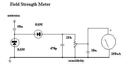 young cove
is that our antenna? which part number?
fallow plank
nah, local retailer didn't have yours
fallow plank

grobotronics.com
Δείτε περισσότερα στην ιστοσελίδα www.grobotronics.com
same accursed shop I got the bad flux, I however couldn't find anywhere alse
They have no text whatsoever on them
RSSI on both sides is close to 20 when close, +-5 side to side
young cove
You could try just tacking a vertical wire to the center antenna output. Then make it straight vertical: https://learn.adafruit.com/adafruit-rfm69hcw-and-rfm96-rfm95-rfm98-lora-packet-padio-breakouts/assembly#wire-antenna-2433240 (pictures there don't show it vertical). Length as specified
fallow plank
Honestly at this point, yolo
I will disconnect the antenna, but not desolder the ufl connector, is that fine?
young cove
70m is getting toward the far range on these
young cove
fallow plank
I will disconnect the antenna, but not desolder the ufl connector, is that fine?
yes
also make sure the sw is setting the frequency correctly. You could also try the Arduino test programs to see if there's some issue with the CircuitPython libraries.
fallow plank
young cove
~~70m is getting toward the far range on these~~
Ah so these modules don't go much further with undirected ants?
young cove
I take that back, that should be fine for unobstructed. I was thinking about inside a house
fallow plank
young cove
also make sure the sw is setting the frequency correctly. You could also try the...
The library is ancient.
Ack code is broken.
Uses ints instead of bools for enabled properties.
No useful error messages whatsoever.
Docs potato.
I will tidy up once I am done getting harassed by the module.
young cove
fallow plank
while 433 does -24
-24 sounds pretty good.
any diff with the wire antennas?
there are a number of range discussions in the adafruit forums
fallow plank
young cove
any diff with the wire antennas?
I want to find the perfect cable first, solid core chopper. It will take me a few days to find it.
worn bridge
little forge
Im wanting to create a number of wearable projects using mainly esp32 s2 QT Py b...
https://learn.adafruit.com/mqtt-in-circuitpython/circuitpython-wifi-usage shows an example of an ESP32-S2 board connecting to Adafruit.io via MQTT. With a bit of modification and some setup on a Pi Zero W, you can have the Pi act as an MQTT broker in place of Adafruit.io (see "Self-Hosted Brokers" under "Connectiong to an MQTT Broker" for details) and send data back and forth that way.
Adafruit Learning System
Learn how to connect your CircuitPython devices to the internet with this lightweight publish/subscribe protocol.
normal drift
azure fox
Anyone have any RFM95 Arduino examples to learn from?
Have you looked at this guide? https://learn.adafruit.com/adafruit-rfm69hcw-and-rfm96-rfm95-rfm98-lora-packet-padio-breakouts/rfm9x-test and at the examples available in Arduino after you install the RadioHead Library http://www.airspayce.com/mikem/arduino/RadioHead/index.html
normal drift
fallow plank
The library is ancient.
Ack code is broken.
Uses ints instead of bools for enabl...
What library are you referring to? This is not "constructive criticism".
fallow plank
Oh sorry, I was talking about the CircuitPython RFM69 library.
I will take care of it myself.
It's pure python afterall.
normal drift
fallow plank
Oh sorry, I was talking about the CircuitPython RFM69 library.
I will take care ...
You are welcome to submit PR's to the repository if you make improvements.
normal drift
fallow plank
The library is ancient.
Ack code is broken.
Uses ints instead of bools for enabl...
What is "broken" about the ACK Code? Please file an issue in the repository if something is broken https://github.com/adafruit/Adafruit_CircuitPython_RFM69
fallow plank
I am incredibly busy these days. I have noted it down and will file proper issues late next month.
University exams.
normal drift
Good luck with your exams!
fallow plank
Thanks.
normal drift
fallow plank
I am incredibly busy these days. I have noted it down and will file proper issue...
FYI -- I did just verify that the rfm69_node1_ack and rfm69_node2_ack examples run as expected on my feather_m0_rfm69 boards with the current library and Circuitpyhton 8.0_rc1
fallow plank
For me the acks always returned true even though node2 was disconnected from power
perhaps I did something wrong then
My code was based on simpletest
I didn't see the ack examples
normal drift
I am not seeing that - mine fail the ack if either is disconnnected.
Wen you have time -- feel free to post your example that is not working (or file an issue).
fallow plank
I will do everything in the issue.
untold needle
Hi guys, I get how to make a band pass filter for my specific values and everything
but how do I make more than one
so one for 26 --> 27.5 MHz and then another for 27.5 -->29Mhz
2 separate
can I make it so that the signal goes to 2 band pass filters
untold needle
@primal warren @granite spear

this is the circuit diagram I have from antenna to filters so far
the top filter is from 1-500KHz
the bottom one is from 500KHz to 2MHz
does this seem right at the moment?
it looks far too simple for me, however that does make sense as right now neither the local oscillator nor antenna circuits are present
half plover
untold needle
it looks far too simple for me, however that does make sense as right now neithe...
Top filter (low band) doesn’t look right
primal warren
untold needle
can I make it so that the signal goes to 2 band pass filters
Yeah, just split it up, run it through the two filters, then recombine. Unless you just want one filter at a time, then you just need some signal switching
untold needle
half plover
Top filter (low band) doesn’t look right
Yeah I'm not sure how to split up the filters
untold needle
primal warren
Yeah, just split it up, run it through the two filters, then recombine. Unless ...
Was my circuit diagram correct
primal warren
untold needle
Was my circuit diagram correct
I'm still fuzz-brained while getting over COVID, so I'm not sure, but it looks to me like you're using one filter as a ground reference for a second filter, and that doesn't seem right to me.
half plover
I feel like it should be a cascading band pass filter
Put either one at the source and then the other in line
primal warren
Like, two in series? I think that would filter out everything, which is why I proposed two in parallel
half plover
Well, I’m not necessarily saying have two band pass filters in series; I’m trying to remember what I’m trying to convey but my brain is fuzzy as well
Not from Covid, just being up all night with sick child 😵
young cove
untold needle
so one for 26 --> 27.5 MHz and then another for 27.5 -->29Mhz
Since these bands are adjacent, I'm confused. Do you want to take the input and direct it to two filters, and then keep their outputs separate? Or do you want to combine their outputs? If the latter, why not a single filter covering the two bands. Also you said these are 27ish MHz filters, but the diagram implies they are AF filters after a mix-down to audio frequencies. What is the use case here?
granite spear
young cove
Since these bands are adjacent, I'm confused. Do you want to take the input and ...
I believe he's trying to measure the signal strength for two different possible transmit frequencies.
untold needle
granite spear
I believe he's trying to measure the signal strength for two different possible ...
I solved this issue now, but now I'm coming up against a fourier transform issue
my professor has told me it wont work due to the nyquist limit
and me not getting enough samples to do fourier
@granite spear do you know about this and can you suggest any possible solutions
due to the nyquist limit I would have to get something like a sample every nanosecond, is this possible, or is there another way with fourier.
granite spear
My understanding was that you were trying to measure frequencies between about 26 and 27MHz, so a 1MHz band? That would ordinarily need sampling on roughly the 1 microsecond scale or a little better for Nyquist, but nanosecond sampling would be a major overkill, I think.
untold needle
 untold needle
granite spear
My understanding was that you were trying to measure frequencies between about 2...
untold needle
granite spear
My understanding was that you were trying to measure frequencies between about 2...
even with mixing the frequency will still be around 0-2MHz
or even 0-3
also how do I sample this quickly
even 1 microsecond or below
granite spear
untold needle
even 1 microsecond or below
It's challenging, as you'd need a relatively high-speed ADC and data-processing path. Not impossible, but it's not easy, so it's worth examining whether you really need to go down that path or if you can do something simpler like just signal-strength measurements at a couple of known frequencies.
untold needle
granite spear
It's challenging, as you'd need a relatively high-speed ADC and data-processing ...
but fourier requires nyquist doesn't it?
granite spear
Yes. The Nyquist limit is a general statement about how much information about frequencies you can get by sampling in time.
untold needle
a high speed ADC is not a problem
untold needle
granite spear
Yes. The Nyquist limit is a general statement about how much information about f...
yes I understand this but we would like to run fourier, we can have a very fast ADC but I don't know what a data-processing path is
granite spear
I mean, you need to be able to store all the data from the ADC and then run a fast-fourier transform algorithm on it, so that requires a decent chunk of memory and CPU power that might be challenging for microcontrollers.
untold needle
granite spear
I mean, you need to be able to store all the data from the ADC and then run a fa...
we don't need to run FFT on the balloon itself
we just need to store enough voltages
to run FFT at ground level
when the balloon comes back down
granite spear
Well, then you need to have a lot of fast data storage instead, so still challenging.
untold needle
granite spear
Well, then you need to have a lot of fast data storage instead, so still challen...
so fourier is looking unlikely?
untold needle
granite spear
Well, then you need to have a lot of fast data storage instead, so still challen...
why can't it all just store on the SD card from the very high-speed ADC
granite spear
It just depends on the time available and the skill level of the folks involved. The real question is, do you truly need it or are you just doing it because someone said it sounded like a good idea? 😉
untold needle
granite spear
It just depends on the time available and the skill level of the folks involved....
not immensely skilled
but you also said fourier seems like a decent idea
so
That was our final plan
until we found out about nyquist
granite spear
untold needle
why can't it all just store on the SD card from the very high-speed ADC
Again, it's not impossible, but the word "just" there hides a lot of complexity, heh heh.
untold needle
granite spear
Again, it's not impossible, but the word "just" there hides a lot of complexity,...
well we have a month
and I'm willing to work quite hard
I'm pretty determined
I also have holidays this coming week
so I could spend 3-4 hours on it per day
granite spear
untold needle
but you also said fourier seems like a decent idea
I probably said it's a decent idea IF you are required to measure exact frequency spectra. But it depends on what your goals are.
untold needle
So I'd say researching and skill wouldn't be the issue here
untold needle
granite spear
I probably said it's a decent idea IF you are required to measure exact frequenc...
exact frequency is what we want
band pass filters are a back up
the sampling rate is the only problem
one sample every 150 nano seconds seems viable
granite spear
Yep, you're going to want something like a 5-10 million samples/sec rate.
untold needle
granite spear
Yep, you're going to want something like a 5-10 million samples/sec rate.
yes something like that
there are 20MSPS ADCs that dont draw too much current
what else is requires apart from a very high speed ADC
half plover
This all playing out like the Digital Spectral Analysis grad class I’m taking
untold needle
half plover
This all playing out like the Digital Spectral Analysis grad class I’m taking
any suggestions to get like 10-20 million samples/sec
half plover
Yeah, one sec
untold needle
thanks
untold needle
jesusa
half plover
A 50MSPS pipelined 8-bit parallel out ADC
half plover
Probably an FPGA
granite spear
Heh heh, and here's where that word "just" pops up to bite you. 😂
half plover
The PRU on that has single cycle gpio state access
untold needle
granite spear
Heh heh, and here's where that word "just" pops up to bite you. 😂
I need this
half plover
Plus 200MHz means you should be able to easily avoid any issues over sampling doing periodogram
untold needle
i only need like 20MHz
half plover
Yeah
half plover
A microcontroller that’s fast enough
untold needle
arduino?
untold needle
RP2040 never heard of it
half plover
PIO on that gives you single cycle access to up to 8 pins on each PIO register
RP2040 is on the Raspberry Pi Pico
untold needle
RP2040 looks pretty good
half plover
135MHz, 2x 8 bit PIO registers that can run independently of the CPU and transfer directly from the registers into your FFTs
half plover
C programming can be hard
untold needle
it cant be just 2
remote pond
i think it doesn't have an FPU so you'd have to use an integer FFT?
half plover
It has a software FPU
untold needle
remote pond
i think it doesn't have an FPU so you'd have to use an integer FFT?
I need to store the voltages
not run FFT there itself
untold needle
half plover
C programming can be hard
isnt it python?
remote pond
hm, can you write 20Msamp/sec to an SD card?
half plover
Ah, yeah just datalogging you can store the ADC values right to a file
untold needle
half plover
Ah, yeah just datalogging you can store the ADC values right to a file
no need for RP2040?
half plover
untold needle
isnt it python?
You can use it but it will be considerably slower
No, rp2040 is necessary
untold needle
for what though?
half plover
Getting the ADC data
untold needle
so it goes through a high-speed adc
half plover
Let me draw a diagram
remote pond
the ADC can't write to flash storage on its own, much less an actual file on a filesystem
untold needle
half plover
Let me draw a diagram
yes please
this seems pretty difficult but I can work hard
half plover
 untold needle
why is there computer
half plover
You can put the data into MATLAB
MATLAB would read the values from a CSV file that the RP2040 would write to
Or a text file, either would work in this case
The PIO data is store in a large array and written to the data file
Then use MATLAB to run all your FFTs
untold needle
half plover
You can put the data into MATLAB
cant I shove it into an SD card as binary or something
half plover
I mean, you could log it to an SD Card but the Pico already comes with 2MB of flash so I’m not sure why you’d want to add additional complexity
untold needle
half plover
I mean, you could log it to an SD Card but the Pico already comes with 2MB of fl...
oh yes
just save to SD Card
half plover
And it can be loaded as a file system directly accessible by a computer
So unless you expecting to log tens of MB of data, I don’t really see it necessary
Adafruit sells a feather with 8MB of flash as well
untold needle
half plover
So unless you expecting to log tens of MB of data, I don’t really see it necessa...
well sampling rate of 20MHz
what coding has to be done on the RP2040
@half plover and is python fast enough
since I'm decent at python but have almost no C expertise though I'm not afraid to learn
remote pond
how long do you need to sample for?
untold needle
remote pond
how long do you need to sample for?
intermittent for like 4-5 minutes at t tiome
time
remote pond
untold needle
intermittent for like 4-5 minutes at t tiome
um, 5 minutes is 6000MBytes of 8-bit samples at 20MHz (edit: ugh, can't arithmetic today)
or do you mean sampling at intervals of 4-5 minutes, but only for enough samples to get a good FFT?
and this is going to be flying in a balloon, right? or was that someone else's project?
half plover
4-5 minutes seems like a really long time
Even systems for like cellular signals only sample for maybe a few hundred milliseconds at most
young cove
@untold needle Do you have to sample the whole band at once? Could you sweep the range with a variable oscillator and mixer? Not sure whether you're trying to get detailed info on signals in a whole band at once or just detect presence.
untold needle
remote pond
and this is going to be flying in a balloon, right? or was that someone else's p...
thats the one
untold needle
young cove
<@623559296784924692> Do you have to sample the whole band at once? Could you sw...
dont have a VFO
young cove
untold needle
dont have a VFO
you mean too late to add one to the radiio part? Si5351?
is the point of this the design part, or could you get an off-the-shelf SDR and do what you want?
untold needle
young cove
you mean too late to add one to the radiio part? Si5351?
plus I think this plan is working
untold needle
half plover
4-5 minutes seems like a really long time
we could do 10 seconds but we arent 100% sure we will get any data
or even milliseconds
we will do 0.1s samples
yes
but @half plover even 0.1s of 40MHz takes up like 20MB or more
remote pond
with the data storage requirements, it might be easier to do the FFT on board. but that means a microcontroller that can compute it fast enough
i guess you could stream a data downlink of the raw samples using a carrier frequency that's not as affected by the ionospheric phenomena you're measuring, but that's also challenging, because now you have a high-bandwidth digital RF link design problem
granite spear
Hahaha, at that point you could just upconvert the received signal directly to a different band and retransmit it.
remote pond
granite spear
Hahaha, at that point you could just upconvert the received signal directly to a...
could be tricky. ionospheric doppler shifts are apparently a thing, though i don't know offhand whether they're large enough to interfere with this particular measurement
untold needle
remote pond
with the data storage requirements, it might be easier to do the FFT on board. b...
We are going to do 50ms intervals
Or 5ma
5ms
We will do 5ms every 5 minutes
Over 3 hours
Every 2 minutes actually
Which is like 0.45s overall
@remote pond @half plover 0.45s total won't take up that much storage surely
Only problem now is will python FFT be fast enough for all the data points
@granite spear i take it you have some expertise in FFT
Will python fourier be fast enough for 0.45s at 30MHz, so effectively 15 million samples
granite spear
Grabbing the data from the ADC will still be tricky, but you should have enough RAM to store milliseconds of data easily, and you can take your time to run an FFT on it or save it to SD Card.
untold needle
granite spear
Grabbing the data from the ADC will still be tricky, but you should have enough ...
I think @half plover suggested an RP2040 to grab the data
And I know python FFT is O(n log n)
granite spear
Yes, a RP2040 can do it. I'm just saying that it will also take some relatively advanced coding.