#help-with-audio
1 messages · Page 1 of 1 (latest)
 dull basalt
 solemn flint
dull basalt
i want to try to make a reel to reel but dont know where to start
solemn flint
dull basalt
i want to try to make a reel to reel but dont know where to start
What does "make" mean to you?
dull basalt
creating a terrible abomination with just enough functionality to play a reel to reel tape
solemn flint
I meant more like, are you planning to wind the coils to make your own motors and stuff like that, or thinking more of buying a cassette player on eBay and trying to adapt it to run on reel-to-reels?
dull basalt
i was planning on using 2 motors i already have- but if its a problem i could try to find one on ebay
solemn flint
(I don't have any particular advice myself. I was just trying to clarify your question enough that other people who might know more would see where you're starting from.)
dull basalt
(ah thx for helping tho)
 median hemlock
I always thought there was some magic in the reels, but I think the magic is in the pinch roller dragging the tape by the head at a fixed rate. Reels are just the practical storage medium! I’ll bet there is a lot of leeway between too little and too much tension.
 terse maple
i think most reel-to-reel tape decks i've seen have used a dual capstan setup, unlike most cassette decks, so they can maintain very stable speed and tension around the magnetic heads
dull basalt
ah
 glacial spruce
While I've seen dual capstan reel-to-reel decks, that's for different play modes, not trying to coördinate tape motion at two places. I will see mechanisms with a spring loaded swing arm that controls the motion of the take-up reel: the capstan sets the speed, drag from the supply reel, idler, and swing arm controls the tension across the heads, and another swing arm adjusts the take-up tension.
median hemlock
I was glib about the reel control and tension not being important; all my DIY efforts are lofi affairs! Tape loops don’t really use the reels.
 pallid latch
So, what you are saying is that it's not a reel issue for you.
 scenic nacelle
High audio peeps, I am using mics for many applications, mostly related to real time, sound-in-the-room, sound reactive artsy stuff (Neopixels, movement, video effects, ...). I started with the inexpensive electret mic such as https://www.adafruit.com/product/1063 . I used them with my CircuitPuthon code on various dev boards (SAMD51 aka M4 boards my fave for sound reactive due to hardware float support). The noise floor on all samples from many vendors of the MAX4466 electrets was horrible badly ruining the sound reactivity. Some can be filtered or perhaps filter some after A->D conversion on the mcu. I also tested with wled on ESP32 variants. There is virtual NO noise. It takes more pins and complexity of PCB or breadboard but not too bad (3 pins vs 1 plus +/- if I recall).

Add an ear to your project with this well-designed electret microphone amplifier. This fully assembled and tested board comes with a 20-20KHz electret microphone soldered on. For the ...
I have sampled many vendors and settled on AITRIP 5Pcs INMP441 in 5 pcs. I tried cheaper and Aliexpress supplied by there was a noticible difference in quality of the parts. https://www.amazon.com/AITRIP-Omnidirectional-Microphone-Precision-Interface/dp/B092HWW4RS/ref=asc_df_B092HWW4RS/?tag=hyprod-20&linkCode=df0&hvadid=532852622530&hvpos=&hvnetw=g&hvrand=12119124758140991084&hvpone=&hvptwo=&hvqmt=&hvdev=c&hvdvcmdl=&hvlocint=&hvlocphy=9001828&hvtargid=pla-1423859966284&th=1 I couldn't find a share or get URL so here it is with my life's metadata embedded.

AITRIP 5Pcs INMP441 Omnidirectional Microphone Module MEMS High Precision Low Power I2S Interface Support ESP32
I tried PWM and I2S other options but these work the same, correctly, every time. Anyone know of a better option around the cost per unit? I anticipate needed at least 20-60 of these round mics. Word of warning: many pages show the pins soldered incorrectly. The side with the mic icon and center hole must face upwards with pins to BB or PCB on opposite side. This is due to mic being the whole so if you mount it the other way you limit it's ability to get clear, full input. Then the mic converts it to digital data on mic and ships the data back over high speed i2S.
this is the correct orientation. This is counter-intuitive because of the way the botton components look. But the mic icon and hole must face up. I adopt a convention of orienting it consistently with the mic icon pointing consistently in one direction that suits the wiring and makes connecting more simple and repeatable.

Love these mics.
Thoughts? Options?
dull basalt
can i use a 3 pin microphone connector on a 6 pin?
i dont know anything about this kinda stuff, im trying to convert a ¼" cable from a microphone to a 6pin microphone cable in a radio
 azure panther
Heya, I'm looking to understand the basics of what I need to do the following: Play music from a single source to a crowd, loud enough to be heard, but not so loud that it's trying to be the only thing that's heard.
I think I need 2 speakers, so I assume I need an amplifier capable of providing sound to two speakers. I also want to play the music from an aux cable.
What should I look for when shopping for systems? I want to find the bare minimum and then something slightly nicer.
glacial spruce
There are a whole bunch of parameters there. PA systems sometimes have speaker arrays directed so people close to them aren't overwhelmed, but people far away can still hear them. Additionally, some are optimized for voice, others for music. What you'll need will depend on the type of sound you care to project, size of area, shape of area, number of people, amount of background noise, etc. You can find very cost effective amplifiers these days, using combinations of class D operation, used equipment, and even inexpensive new designs can perform well. Most of the expense will generally be the speaker arrays.
azure panther
Doe this amp look suitable? https://www.outdoorspeakerdepot.com/amplifiers/stereo/60w-class-d-digital-stereo-mini-power-amplifiermic-mixer-with-source-sensing-and-bridge-xmp60.html It's a nice price.
glacial spruce
Beats me, it's hard to tell by looking.
azure panther
Hm ok. I have some 70V outdoor PA speakers I can use. How can I tell if a nW amp has 70V outputs?
glacial spruce
I'm not sure what a nW amp is, but most will have speaker specifications. You can, of course, use a matching transformer to convert a low impedance speaker output (such as 8Ω) to 70V, but that's more parts, expense, and complexity.
azure panther
n as in "en" as in any given number. Sorry, wasn't clear. Thanks for the input
glacial spruce
For example, the amplifier you linked to can drive 4Ω or 8Ω loads, but doesn't have a 70V tap available.
azure panther
I have to say the 70/25V designation vs 4 or 8 ohm is simply confusing to a newbie
glacial spruce
Note that some 70V speakers are ordinary low impedance speakers plus a matching transformer. If so, you can wire around the transformer and drive the speaker directly.
azure panther
so the audio is an AC signal then?
back and forth?
I thought it was DC for some reason
glacial spruce
Yes, audio is an AC signal. Human hearing notionally covers from about 20Hz to 20kHz, so audio signals are generally in a similar range.
glacial spruce
That's kind of how the class D amplifiers work, they modulate a high frequency signal with PWM in order to offer efficient amplification. The high frequency signal is then filtered out (in some cases by the inductance of the speakers themselves), yielding an audio frequency envelope.
azure panther
interesting
glacial spruce
I actually bought a "100W" amplifier from a Far East manufacturer recently for $39, it seems like a decent unit but I rather doubt the power claim (I haven't measured it yet)
azure panther
I'm looking at a 60W unit for my purpose
glacial spruce
That seems reasonable. There are youtubers (such as Williston Audio Labs, Zero Fidelity, and cheapaudioman) that buy and review inexpensive amplifiers, they can be a useful resource.
azure panther
100 bucks will cost everyone less than paying me to learn how to save 30 bucks
glacial spruce
That kind of rational thinking is rare these days, good on ya
azure panther
I don't always exhibit it, but I try. Sometimes people like seeing lower BOM costs, even if it takes longer. Doesn't make sense but...
glacial spruce
Sometimes it makes more sense than others: the trick is figuring out when!
If you're building a million of something expected to be used for a couple of years, it makes sense to save a few cents on cheap capacitors. However, if I'm building/repairing one of something, the cost of my time is much higher than most components, so I use fancy 10000 hour 125°C capacitors or even polymer ones. But those cases are easy to identify. Choosing a small amplifier to power my ancient Radio Shack Minimus 7 speakers seems like a much harder problem to optimize (I ultimately opted for a floor model AudioEngine N22 on a nice markdown)
glacial spruce
Those are dandy for power supply bypassing, but I'll tend to prefer film capacitors when I want more stability.
azure panther
I just meant where appropriate, as an example of something spendy
glacial spruce
Ah, got it
azure panther
glacial spruce
Ah, got it
How critical is outdoor rating for...outdoor use?
for wire
glacial spruce
There are a few failure modes wires can have when used outdoors. The main ones I'm aware of are water ingress and UV damage. You can often get away with it, at least for a while.
azure panther
hmm
it's 40 bucks for what I need. Not worth having 70V conducting where I don't intend
 earnest stratus
Hi @pearl depot - did you ever make this work? I'm looking at a very similar application where using the Music Maker FeatherWing and want to directly write the audio files to it over SPI instead of pre-loading them on a computer.
glacial spruce
earnest stratus
Hi <@484468443513618437> - did you ever make this work? I'm looking at a very ...
The SD card supports an SPI(ish) interface, so this might be reasonably straightforward
earnest stratus
SPI(ish) sounds close enough for me. Thanks @glacial spruce
dull basalt
dull basalt
can i use a 3 pin microphone connector on a 6 pin?
help
glacial spruce
dull basalt
can i use a 3 pin microphone connector on a 6 pin?
Mmmmmaybe. It depends on the microphone and the radio. Sometimes you just need to adapt the wires, other times, you'll need to add a little circuitry.
dull basalt
ok thx
its not realllllyyy coming from my mic but from my mic to my pc to a sound card to the radio
glacial spruce
You might have to do some level matching and/or impedance translation, and possibly some ground loop isolation. It's not that hard, but the details depend on the particular setup you're building.
dull basalt
ok thx
 karmic needle
How does one go about getting higher/better quality audio from a microprocessor?
Assuming that something like a MAX98357 is low quality, what should I be looking into to get better quality?
- Is I2S good enough?
- Is it a better DAC, e.g. ES9023?
- Not just the DAC, but also the circuit design and components around it?
FYI, I'm looking at ESP8266, ESP32 or anything equivalent as a microprocessor.
(If that helps in the context of my question)
glacial spruce
You're on the right track. Other factors include resolution and sample rate, but in my experience the biggest factors are the circuitry and digitized audio quality. For example, a 2V signal with 16 bit resolution works out to a little over 30µV per bit. All sorts of noise and linearity issues can affect things at that level.
karmic needle
What's a good compromise for a hobby project? e.g. I feel like using MAX98357 may not be good enough for my project, but I also don't want to be designing my own DAC circuitry.
DAC/audio circuitry seems like wizardry at times. The audiophiles lose their minds over it.
I'm not aiming for audiophile quality either. I just want something that sounds clean.
Should I just use an existing DAC board then use I2S to connect to it?
(Will that be enough, or will I somehow face other problems?)
(Btw madbodger, you're always around to help people. I swear you're a god here)
glacial spruce
I have no way of evaluating what would be "enough" in your case, but an existing DAC board + I2S seems reasonable to me.
karmic needle
glacial spruce
I have no way of evaluating what would be "enough" in your case, but an existing...
I discovered the ESP32-A1S which has an audio codec chip under the shield. (Either ES8388 or AC101).
I'm still chasing down how good the audio quality is on these devices, but I suspect this might be a good starting point for the project.
 young spire
Late to the talk, but shielding and ground loops are two big things to watch for.
 last prawn
Yeah - its going to be extra tricky on a dev board with a wireless adapter
 drowsy tiger
I'm working on a project for a chip that plays sound upon power being connected to it however I want to add more sound files and be able to select which sound file plays upon powering up. Anyone willing to take a look and help me out? Amazon comments told me that adafruit has a product for it but I am a total noob.
solemn flint
drowsy tiger
I'm working on a project for a chip that plays sound upon power being connected ...
Possibly they were referring to https://www.adafruit.com/product/2217

Would you like to add audio/sound effects to your next project, without an Arduino+Shield? Or maybe you don't even know how to use microcontrollers, you just want to make a sound play ...
drowsy tiger
solemn flint
Possibly they were referring to https://www.adafruit.com/product/2217
That def looks like what would do the trick. It has 11 triggers to play different sounds. I am more looking to make it something like this: https://www.youtube.com/watch?v=-a9V3zV7vkY

Preview of tracks from the Ressha melody box.
Inspired by my trips to Japan, it's hard not to miss the sights and sounds. You'll hear various greetings while travelling Japan but train stations are particularly known for their station-specific tunes. This melody box plays a selected track when it detects power and includes volume control. Choo...
Do u know any products that could help me create something like it?
glacial spruce
AdaFruit offers some Music Maker wings and shields, some with built-in audio amplifiers, that let you put a bunch of sound clips on an SD card and play them back.
drowsy tiger

Would you like to add audio/sound effects to your next project, without an Arduino+Shield? Or maybe you don't even know how to use microcontrollers, you just want to make a sound play ...
You guys know if this comes with everything shown in the picture?
glacial spruce
drowsy tiger
You guys know if this comes with everything shown in the picture?
No, it just comes with the board itself and the terminal blocks for hooking up speakers.
drowsy tiger
glacial spruce
No, it just comes with the board itself and the terminal blocks for hooking up s...
Does adafruit sell the rest of the items shown in the pic?
glacial spruce
I think so? Maybe not those exact speakers, but you should be able to pick up a breadboard, AA cell holder, speakers, wires, etc.
azure panther
How can I tell if an MP3 is compressed or not?
azure panther
I'm trying to figure out if the 16MB of flash on the VS1053 board adafruit sells is enough for a 10MiB Mp3
solemn flint
azure panther
How can I tell if an MP3 is compressed or not?
"Is it an MP3? Then yes, it's compressed."
solemn flint
I don't have the context of the guide, but some use cases would need to convert the MP3 back into a WAV file or equivalent raw audio to play it.
azure panther
hmmm
let me see if I can find it again
It's sort of moot because I'm going to use the version with an SD card
 stable iris
Sometime mp3 are almost uncompressed
but there is still some
Also wheter 16mb is enough depends on how smart the decoder is with buffers
The worst thing would be a decoder that convert it to a wav in memory (seen it before...)
dull basalt
Hi everybody. Does anyone use I2S microphone (SPH0645) with circuitpython ? I'm trying to wiring this kind of micorphone on a Raspberry Pi Pico but I don't have fin documentation about it.
 weary gyro
dull basalt
Hi everybody. Does anyone use I2S microphone (SPH0645) with circuitpython ? I'm...
weary gyro
dull basalt
Hi everybody. Does anyone use I2S microphone (SPH0645) with circuitpython ? I'm...
Not possible at the moment, I think. PDM microphones is currently the only supported audio input for CircuitPython as far as I know
dull basalt
Hello, does anyone know how to convert a wav file into an array ? Then I want to manipulate array with ulab
last prawn
dull basalt
Hello, does anyone know how to convert a wav file into an array ? Then I want to...
I'm guessing the example there gets you most of the way there
 hasty crater
I could be wrong but I don't think audiocore works on all boards anymore. Might have been dropped for audioIO and audiomixer. You'll have to look into it.
I'm guessing what you'd be interested in is putting rawsample into array and those examples are showing audiocore.
If I'm right then might save you some time and effort if you hit a wall and can't get audiocore to work with your code.
last prawn
hasty crater
I could be wrong but I don't think audiocore works on all boards anymore. Might ...
It might - I just looked at the docs really quick to see if there was a circuitpython way. I think in reality I'd probably just grab any wav loading library and load it up (or quickly write one that just throws away the header)
 fair forge
Good morning! I couldn't find anything in the learning guide, but is there a way to make a voice recorder with Circuit Python? My Pyportal Pynt already has an SD card and a speaker. If I add a mic, I just need code to complete it. Thanks!
last prawn
fair forge
Good morning! I couldn't find anything in the learning guide, but is there a way...
Its hart to tell if the i2s pins are available or not on the pyportal pinout (lots of similar colors) but if they are available you're best bet is probably one of the i2s mems microphone breakouts
It looks like they might not be exposed
fair forge
Thanks! Though the hardware isn't the issue... I've been looking for a good sketch to record and play back.
last prawn
Do you already have a microphone attached or are you trying to do the "record through the speaker" trick?
Most of the sketches available for doing this use i2s and zeroDMA (and tend to not play nicely with things like screens)
fair forge
I've got a mic but haven't hooked it up yet... But I'm familiar enough with the hardware, I don't need any help with that. I just couldn't find a sketch that does "record". I was just looking through the Learning Guide, so if there's another resource out there, that would be nifty.
But actually, I just found a little piece of hardware that does everything I need that's standalone... So all this is probably moot.
last prawn
What I'm getting is that "record" is meaningless unless we know how your mic is connected. If you're just connected to an analog pin then you're really just datalogging analog signals so anything that logs analog data to the SD card will work. If you want to convert it to a normal audio fileformat theres a little more work. If you're connected to something thats using a protocol like i2s,i2c,spi then you need to interface with that based on what the chipset is doing, etc
fair forge
Gotcha... However, it is moot since I just purchased a standalone Voice Recorder Module from DFRobot. I thought it would be easier to do this on the Pynt, but this thing does everything I need and no programming necessary. Just plug and play.
Thanks for your help though!
 tall mango
I got a new/old CD player recently and for some reason the bass is really distorted and keeps peaking really easily, i even compared it to a rip of the same CD and it's definitely too loud. There's no volume adjustment so I'm wondering if there might be a specific potentiometer on the inside that deals with the amplifier's peak volume? The model of the player is JVC XL-V 112 BK.
I even replaced a few leaky capacitors near the audio output
There's an internal potentiometer labeled "TRK GAIN" and another labeled "PLL ADJUST", but there's an unlabeled potentiometer next to the first one


 unborn drum
didn't get any answers in the circuitpython chat so I'm trying here too: in circuitpython, audiomp3 seems only accept an mp3 as an io.fileIO object (as created by open ) and doesn't accept an mp3 file I have in memory (stored in a byteIO object). Both types inherit the same io.RawIOBase class, and I think both contain the same stuff (a stream of bytes). I know I could write out my mp3 to the file system and read it back in, but maybe someone has a better way?
stable iris
having the whole mp3 in memory kinda kill the point of mp3 as per the hoffman algorithm...
it's supposed to buffer a small part of the raw audio in memory
unborn drum
I'm receiving this audio over serial, so mp3 was chosen to fit within the bitrate. Therefore, I happen to have the mp3 in memory and not on the filesystem
stable iris
do you have the whole mp3 in memory or just a part? what are you using to read the serial data (audiomp3 must have the mp3 in contigous memory to work)
unborn drum
its a small mp3 file, 32kb. I get the file like this and I write it to the filesystem(for now):
while True:
    if serial.in_waiting > 0:
        myAudio += serial.read()
    elif serial.in_waiting == 0 and len(myAudio)>0:
        break

f = open("myAudio.mp3", "w")
f.write(myAudio)
f.close()
then later I open the mp3 again:
audio = AudioOut(board.A1)

while True:

     audio.play(decoder)
print("playing")```yeah so far with all the research I've done that's all you can do I think
that library doesn't support reading the audio from memory and need a file for sure to read the frames in the mp3 correctly
I looked at the code for it and I'm fairly certain of what I say
The only way around I'd see is to fool circuitpython into thinking the file you have in memory is an actual file throught another circuitpython library
unborn drum
thank you for looking! It's a shame, because the byteobject "myAudio" is functionally identical to the fileobject that gets created later when I open my saved mp3.
stable iris
I doubt they will be able to do it as playing a bitrate above 44khz is difficult on some board and this would probably need more performance (having part of the mp3 in memory twice), but I'd open an issue / suggestion if I were you
stable iris
unborn drum
thank you for looking! It's a shame, because the byteobject "myAudio" is functio...
no problem, I know you waited for a while but sometimes it takes a long time to correctly answer a question
terse maple
unborn drum
thank you for looking! It's a shame, because the byteobject "myAudio" is functio...
is it the same, though? i think bytesrray can be fed to io.BytesIO, but is not the same. did you try creating a BytesIO object from it?
unborn drum
terse maple
is it the same, though? i think `bytesrray` can be fed to `io.BytesIO`, but is n...
You are correct 🙂 I recently deleted the BytesIO code i was using so I can't easily reproduce the error, but audiomp3 really wants a FileIO object
stable iris
terse maple
is it the same, though? i think `bytesrray` can be fed to `io.BytesIO`, but is n...
from the code it seems it needs a structure that it simply different from a mp3 that it make from the file and keep referering to file-> (for reading the next frame for instance), also assumed that having a file insure that the memory will be contiguous as it warns about
probably wouldn't need that much to have a version that can read it from memory instead of a file but didn't seem possible currently
terse maple
unborn drum
You are correct 🙂 I recently deleted the BytesIO code i was using so I can't ea...
yeah, it seems to specifically look for mp_type_fileio, which might actually contradict its official documentation, though i'd have to read more carefully to be sure
unborn drum
terse maple
yeah, it seems to specifically look for `mp_type_fileio`, which might actually c...
would you be so kind as to point me to where you see that?
i was digging around for the source but having trouble locating it
unborn drum
terse maple
https://github.com/adafruit/circuitpython/blob/main/shared-bindings/audiomp3/MP3...
you're the best!
stable iris
I went to the circuitpython dev channel and asked the same question, was puzzled that github couldn't find a core library in circuitpython code 😄
oh well at least it gave me a sorta good question to ask in the dev channel
unborn drum
i think I'll collect the info here and open an issue on github. the documentation does seem to imply a BytesIO object should work, and maybe it's easy to change the source to be more inclusive. Thank you for the help @terse maple and @stable iris! On the plus side, I have now learned how to switch between USB and circuitpython having file system access 🤣
unborn drum
for anyone playing along at home: https://github.com/adafruit/circuitpython/issues/6850
tall mango
Im trying to use an I2S DAC to debug a CD player DAC but for some reason the output is just very even white noise, what does this mean? The IC that usually recieves the I2S signal is a SANYO LC7881, and im using the UDA1334 DAC.

Maybe i missed a required pin?
solemn flint
tall mango
Im trying to use an I2S DAC to debug a CD player DAC but for some reason the out...
You might check to see if you have an endianness mismatch or something, like reading the most-significant byte in a 16-bit audio value as the least significant. That'd scramble everything up and look like random noise.
tall mango
Is there a way to change the endianness to read most significant byte on the Adafruit I2S decoder?
The back of the board doesnt specify MSB, only LSB and I2S (default)
karmic needle
Does anybody know how you would go about syncing sound across multiple microprocessors driving speakers? (Over a network)
I know Logitech Media Server does this. I'm still trying to understand how this is done by reading the source code.
Any other info or tips would really be appreciated.
 late arrow
karmic needle
Does anybody know how you would go about syncing sound across multiple microproc...
late arrow
karmic needle
Does anybody know how you would go about syncing sound across multiple microproc...
I don't know, but if you're looking at source code, maybe check out snapcast: https://github.com/badaix/snapcast
karmic needle
Ah this is great. I was actually thinking about dropping frames or adding a very small delay to try and bring streams back in sync.
Never thought to use time synchronization but that makes total sense
Thank you so much for this
azure panther
The featherwing for the vs1053 with a headphones jack uses this circuit for a reason I don't know.
- is this just filtering?
- does any circuit from a chip that advertises it can go to a headphones jack need this?

 dusty rivet
azure panther
The featherwing for the vs1053 with a headphones jack uses this circuit for a re...
dusty rivet
azure panther
The featherwing for the vs1053 with a headphones jack uses this circuit for a re...
The answer to your first question is yes, notice the note that says C1,C2 specified for a 20Hz cut off? Good indicator that’s what it’s used for if you see that.
azure panther
Sorry I'm operating at a low level today, I have a migraine
stable iris
also 20khz is normally the average limit of human hearing
not much point going above, hence cutoff
dusty rivet
20Hz is the bottom end of what we can generally hear as well
stable iris
I don't know why those specific ohms though
they are the same which is obviously to get the same volume on both R-L
but I don't know why 100 ohm in particular
dusty rivet
100ohm is probably current limiting
Or they’re using it in parallel with the 22ohm to get 18ohm load
stable iris
aren't they normally like 100k ohm because of op-amps ?
stable iris
also what kind of resistor is rated for letters instead of numbers ? 🤣
resistor says ZZ
 stable iris
but don't they calculate ZZ before they put it in a schematic ?
dusty rivet
My guess is the additional circuitry is for filtering sub 20Hz noise
dusty rivet
stable iris
but don't they calculate ZZ before they put it in a schematic ?
No idea, they supposedly changed the antenna matching network on some of the ESP32 qt py but some of them ship with just 0 ohm resistors lol..
They make a ton of designs so it’s very likely just a small oversight
stable iris
at least now I know that if the sound of a speaker is bad I can jusst hook a 500ish iF cap on each side and a small resistor for higher-fidelity
azure panther
stable iris
resistor says ZZ
I'm fairly certain it's 22
Basically I want to look into the dfrobot dfplayer mini and I'm not sure if I need this filtering or not. They don't give nearly as much data to their customers as adafruit does
stable iris
dusty rivet
Perhaps, I’d have to look at the data sheet though
datasheet is alledgedly only available in business and seems to be a digital "black box"
dusty rivet
stable iris
datasheet is alledgedly only available in business and seems to be a digital "bl...
For the vs1053?
stable iris
*in chinese I meant 😄
dusty rivet
stable iris
my google-fu isn't what it used to be apparently
azure panther
I'm looking at MP3 player boards. How do I decide if I want mono or stereo? I want to output to a headphone jack that then goes to a traditional amplifier
 lethal slate
You want stereo. It is possible to feed a mono signal into both channels but stereo is better.
I guess it depends on your mp3 files. No point in mixing it down to one channel if your amplifier has two.
azure panther
ok so what kind of headphone jack do I need?
azure panther
lethal slate
You want stereo. It is possible to feed a mono signal into both channels but ste...
Do you know if the raspberry pi uses stereo or mono? I ask because the speakers I use with my pi are only TRS, which feels like mono to me, and it works fine
lethal slate
What kind of jack is on your amplifier? TRS is stereo, mono would only have Tip and Sleeve.
azure panther
let me check.
I'm actually pretty sure I'm OK with just using mono
Given the options
Well the DFPLayer mini says it's mono but it connects to tip, ring, and sleeve?
Like it has a DAC_L and DAC_R output
azure panther
Which of these is traditionally tip/ring/sleeve?
 weary gyro
azure panther
The featherwing for the vs1053 with a headphones jack uses this circuit for a re...
weary gyro
azure panther
The featherwing for the vs1053 with a headphones jack uses this circuit for a re...
This is the recommended output filter for headphones, as described in the VS1053b datasheet: https://cdn.sparkfun.com/datasheets/Dev/Arduino/Shields/VS1053B.pdf
weary gyro
azure panther
Which of these is traditionally tip/ring/sleeve?
1 = sleeve, 2 = ring, 3 = tip
but test out your jack to be sure
azure panther
weary gyro
This is the recommended output filter for headphones, as described in the VS1053...
where'd you find it in the sheet? Searching isn't working out
weary gyro
azure panther
where'd you find it in the sheet? Searching isn't working out
I typed "vs1053b datasheet" into google
azure panther
no sorry, where in the sheet did you find the recommendation?
weary gyro
azure panther
no sorry, where in the sheet did you find the recommendation?
it's the first (and I think only) schematic, figure 3. Here's that, with the headphone output part highlighted in yellow
 weary gyro
looks like adafruit added some extra DC-blocking capacitors (and perhaps current-limiting resistors?) after the recommended RC filter. This may be talked about more in the datasheet, but I didn't see it. It may be common on hobby-level audio stuff where we're hooking our audio outs to other potentially harmful things 🙂
azure panther
yeah I'm trying to figure out if this other board I'm looking at implements something similar but the only thing to do is to email the mfr
Which I've done.
weary gyro
If you're talking about some rando board off Amazon or Aliexpress, in my experience they almost always implement the minimal reference circuit from the datasheet
(for chips in general, not this particular chip)
azure panther
It's from DFRobot so not super rando
azure panther
I'm looking at the DFRobot player mini for my needs and it seems to fit fine, but i want to output to an amp via headphone jack. Looking at the chip onboard's datasheet (YX5200-24SS), it has a separate ground for the DAC. However the DFRobot chip doesn't break this out. Is this a red flag?
Basically what are the major downsides of using power ground for DAC ground?
glacial spruce
Sometimes there will be digital noise on the power ground, which can get into the audio channel if they're shared.
azure panther
hmm ok
so I was thinking of in the future making boards with the actual chip on DFrobot just my own design. I would need two ground planes, right? Connected at one point?
azure panther
glacial spruce
Sometimes there will be digital noise on the power ground, which can get into th...
But it's not necessarily a complete failure mode all the time? Like it might work fine?
glacial spruce
Yeah, it often works fine. Once in a while, you might notice a squeak or crackle in the audio under some circumstances.
azure panther
that's tolerable in my case
but I'll want to fix that for others
unfortunately this chip is an ali express special so I can't get it quickly
So I'll have to live with the less than ideal design for now
azure panther
glacial spruce
Yeah, it often works fine. Once in a while, you might notice a squeak or crackl...
Thanks
 twin vessel
Do you knows know how I could get a speaker and microphone onto my raspberry pi zero w? I was looking over a bunch of options like the speaker bonnet (which i don't think has a microphone input). anything i could get that would help?
 cinder briar
twin vessel
Do you knows know how I could get a speaker and microphone onto my raspberry pi ...
cinder briar
twin vessel
Do you knows know how I could get a speaker and microphone onto my raspberry pi ...
There are some things on Amazon (like a pHAT by waveshare that has 2 audio out channels and 2 mic in channels (2 mems mics onboard). There are also some things by Pimoroni.
Adafruit might have something, but I've never looked at that
twin vessel
i'm gonna just be doing usb input/output
i have a usb hub
and i'm buying a small usb speaker and microphone
glacial spruce
That's like another level of indirection and less specific to a Pi, but as long as there are drivers for it available for the Pi, it should work.
 tepid grove
I admit to using one, some £3-5 mic/audio usb for laptops, repurposed like everything into the land of Pi's
 harsh gust
Hellow everyone!
Idk if you guys still remember but I have asked quite a lot of questions in this channel around April and May regarding piezo amp circuits.
I copied and pasted, and documented some of the question-answers in my OneNote and I see @glacial spruce helped me a lot haha Thank you.
I am not sure if I shared the result, but here is the result.
I displayed it in my school expo on May 5th. It was a great experience.

"Anthesizer I" is a track consisted of audio clips from Anthesizer, an audio-visual exhibition held at CalArts Expo 2022.
Anthesizer is an audiovisual exhibition featuring Harvester Ants, Pogonomyrme
This is an extended version of ambience track made out of the recordings.
Back then I used a really crude circuit design that had a clear electric humming noise in the background.
But now I'm trying to come up with a better circuit with lower noise. So I brought this up to one of my faculty members at my school today.
Telling him that I want to build a piezo amp circuit specifically being used for taking micro sounds that ants create.
I told him that I want to build this circuit -> http://www.richardmudhar.com/blog/piezo-contact-microphone-hi-z-amplifier-low-noise-version/
But he told me it is a wrong pursuit and it never works. He suggested me to use a prebuilt preamps or audio interfaces in the market, and he told me he thinks it's not necessarily the problem of the preamp circuit.

This is the purist approach solution to the tinny contact mic sound problem if you want the lowest electrical noise, or the lowest distortion at higher levels. Piezo mics aren’t usually considered …
What do you guys think? It would be nice if yall can share your opinions.
glacial spruce
harsh gust
I am not sure if I shared the result, but here is the result.
Cool, that came out well, nice build!
glacial spruce
harsh gust
I told him that I want to build this circuit -> http://www.richardmudhar.com/blo...
I'm not sure I'd agree with "it's a wrong pursuit" or "never works", but for low-level signals like that, you do need careful layout and shielding to ward off unwanted noise pickup. The techniques aren't necessarily difficult, but they're somewhat subtle and it can take some time, thinking effort, and iteration to come up with an implementation that works well. Some people prefer to just buy a finished module, others enjoy the process and learning that comes with working it out themselves (I am firmly in the second camp).
harsh gust
glacial spruce
Cool, that came out well, nice build!
Thank you!!
harsh gust
glacial spruce
I'm not sure I'd agree with "it's a wrong pursuit" or "never works", but for low...
I am not trying to accomplish everything quickly. I am thinking of doing it again on next school expo which might be next year May 5th. So I have plenty of time until then.
I have a beginner experience of messing around with very simple circuits with arduino starter kit last semester. And I'm learning basic theory on mathtutordvd.com
so for example if I am gonna build this circuit
 harsh gust
I told him that I want to build this circuit -> http://www.richardmudhar.com/blo...
harsh gust
harsh gust
I told him that I want to build this circuit -> http://www.richardmudhar.com/blo...
I think I can do, but I don't know how I am going to be able to build the circuit above
terse maple
if you can find one, an analog oscilloscope is a valuable learning tool for working with analog circuits. i feel like it's too easy to "get lost" navigating a digital oscilloscope if you've never used an analog one as a reference point
harsh gust
ohh I have never used it. Isn't it super expensive?
or are you talking about practicing reading circuit diagram?
terse maple
no, i mean an actual physical CRT analog oscilloscope. they show up in the used market from time to time, sometimes for cheap, and you don't need more than a few MHz of bandwidth to do most audio work
harsh gust
terse maple
no, i mean an actual physical CRT analog oscilloscope. they show up in the used ...

stuff like this?
agh, ppl online say that I can build the circuit even without necessarily knowing exactly how all the things work together
I would like to know what is the best practice to achieve the ability to read the diagram and build it right away
terse maple
it's somewhat true that you don't need a deep understanding of how the circuit works to build it. it's also true that some understanding of what the critical parts of the circuit are will help you build it in a way that has the fewest problems (unwanted oscillations or noise)
harsh gust
terse maple
it's somewhat true that you don't need a deep understanding of how the circuit w...
ohh so true
like the way ppl here helped me out with my problem last semester 😵😵
harsh gust
terse maple
if you can find one, an analog oscilloscope is a valuable learning tool for work...
but what else do I do with analog oscilloscope?
glacial spruce
There's not a whole lot you can do with them, they're built for viewing signals and that's what they do best. However, you can use them to visualize music, do "scope art", movie props and the like.
harsh gust
glacial spruce
There's not a whole lot you can do with them, they're built for viewing signals ...
ahhh got it got it. Thank you so much always!
 native furnace
Hey all, i have some questions
is there a small form factor mp3 audio player with an amp
cinder briar
Dfplayer mini?
native furnace
i went with the audio fx with amp, it doesnt need a seperate microcontroller


The recent meme on the chinese internet.
KFC had released a Psyduck toy on the 21st of May,
Since then, Psyduck has become quite a delightful and viral meme in China.
Chonky, yet energetic.
Pathetic, yet upbeat.
Why, he's full of contradictions! And perhaps reminiscent of Chinese people doing their signature park exercises.
Anyway, w...
im purchased this toy from taobao, gonna try to mod it to play "the duck song" instead
azure panther
I bought this (https://www.digikey.com/en/products/detail/sparkfun-electronics/BOB-11570/6006052?utm_adgroup=Adapter%2C Breakout Boards&utm_source=google&utm_medium=cpc&utm_campaign=Shopping_Product_Prototyping%2C Fabrication Products&utm_term=&utm_content=Adapter%2C Breakout Boards&gclid=Cj0KCQjwmouZBhDSARIsALYcouqIjGBgbkvpyJqCM1qJsHgyBIQNQMYEcs3BDcTBJG_hLdWvSeTAzXYaAiPpEALw_wcBl ) is it useless with a normal TRS plug?
glacial spruce
azure panther
I bought this (https://www.digikey.com/en/products/detail/sparkfun-electronics/B...
That should work with a TRS plug, it'll just connect the plug sleeve to both sleeve and ring2 on the breakout. Tip is still tip, and ring1 is ring.
 opaque eagle
Okay so thus far most of my electronics work has been digital, but now I'm trying to build a passive mixer. I have a design, but I'm concerned a line level signal won't "get through" it. Basically, I have six stereo inputs, each runs through a 10k stereo log pot for mixing purposes and then a "mute" DPDT switch. those all join into one stereo signal, which goes through a master 10k stereo log pot, then a 1k ohm resistor on each channel (I don't know why you would do this? The guide for a simpler mixer on Adafruit does, though, and I assume they know what they're doing). Then it goes into a bank of DPDT switches that route it to one of four outputs. Is there anything to be concerned about here?
I feel like even just the two pots the signal runs through would result in some significant loss in volume, even if they're both in their minimum resistance position
So maybe this needs to be an active mixer?
dull basalt
I had a circuit diagram for this. Passive mixing gives rather poor results, especially with changing inputs ("I want to hear that channel just a bit louder, let me turn this knob and..")
Fortunately they are still publishing the article:
https://sound-au.com/articles/audio-mixing.htm
Keep in mind that potentiometers are not power oriented, they are signal oriented. They're for line-level signals, rather than amplified signals.
Radio Shack used to sell an 'L-Pad' (wirewound rheostat) to control loudspeaker volume, designed to handle the fully amplified signal (probably 5-10 Watts) which was wall-mounted like a dimmer for a ceiling lighting fixture.
opaque eagle
I ran a soundboard for a theatre production a couple months ago and since the cast wasn't mic-ed I was only in charge of the occasional sound effect. I had a lot of down time to learn how mixers work in practical application but the actual circuitry is my next frontier
glacial spruce
opaque eagle
I feel like even just the two pots the signal runs through would result in some ...
You want a series resistor protect the inputs from being shorted to each other if more than one pot is turned to 0 resistance (that may be what the 1k one is but I don't have the schematic handy). The loss in volume shouldn't be too much. Passive mixers are generally fine.
azure panther
Having an issue that I'm trying to track down the source of. Using a cheap headphone jack I am connecting a DF player mini to speakers. Previously I connected to headphones and had the same issue I'm going to describe.
So one speaker/headphone is really quiet. But I brought both channels up on a scope and they seemed fine? as far as I could tell at least by just looking
it feels more likely that it's the headphone jack. Am I far off?
glacial spruce
Yeah, probably dirt, a cracked solder joint, or something has lost spring tension
azure panther
My next step is to get some cheap normal headphones (Bluetooth gang) and hold some wires up against the contacts. It doesn't really matter for this test whether I put L on L and R on R, right?
And is this correct?
 glacial spruce
It depends: there are two common standards for TRRS. What you have illustrated is the CTIA pinout. The other one (OMTP) has ground and mic swapped, so ground is one the sleeve, and mic is on ring 2.
CTIA is used by Apple (and others), OMTP is used by Nokia (and others). There are also a few other variants in existence like using the "mic" lead for video, and a camcorder standard where tip is still L, but ring 1 is video, ring 2 is ground, and sleeve is R.
glacial spruce
You can often figure out which lead is ground, as it should have similar resistance (generally between 8 and 32 ohms) to both the L and R signals via its transducers
azure panther
glacial spruce
You can often figure out which lead is ground, as it should have similar resista...
OK I'm getting 46-51 ohms (it varies) for between TIP and RING2 and RING1 and RING2. 700ish ohms to sleeve
It seems that RING2 is ground?
glacial spruce
Yeah, seems like it. For a cross check you can measure tip to ring1, it should be about twice the value for either of them to ring2.
azure panther
what's the difference between volume and volume gain? I'm looking at a datasheet for a chip and it has options for setting the volume and the "volume adjust" or "volume gain" (the english is imperfect).
solemn flint
Possibly "volume" is like adjusting the output to a fraction of 0.0-1.0 of the input level, whereas volume gain means the baseline 1.0 point is actually amplifying the input by X amount. I am just guessing, though.
 hollow coral
Hi,
I have a couple of these speakers. How can i use these with a microcontroller to play music. I have a nano rp2040 connect. What additional hardware will be required to do so. Don't know much abt the specifications of the speaker. Also don't know if this is the right place to ask.
 glacial spruce
hollow coral
Hi,
I have a couple of these speakers. How can i use these with a microcontroll...
glacial spruce
hollow coral
Hi,
I have a couple of these speakers. How can i use these with a microcontroll...
Basically you need a source of audio and an amplifier. AdaFruit offers some "Music Maker" shields and wings that include a SD card slot (to hold the music), an MP3/Ogg decoder chip and (optionally) an amplifier to drive speakers. They're fairly low power amplifiers, but may be sufficient depending on how efficient your speakers are, and how much volume you need. You can use separate amplifiers if you need more power (AdaFruit offers a 20W stereo one, if you want more than that, there are plenty available). Most speakers present an 8 ohm impedance, but there are some that are higher or lower. Most amplifiers will work with most speakers, if the impedance doesn't match, you'll just get less volume before they start to sound distorted.
 icy vine
Hi everyone! double posting here. If that's not allowed please go ahead and delete. I have audio playing from an SD card to a small speaker using a QT Py ESP32 Pico and CircuitPython. I need to port the code over to MicroPython though. Does anyone have any experience with this that might be willing to help?
I've been trying to port it over myself but havent had any luck
 flint narwhal
icy vine
Hi everyone! double posting here. If that's not allowed please go ahead and dele...
flint narwhal
icy vine
Hi everyone! double posting here. If that's not allowed please go ahead and dele...
Can you provide a some more detail on what you have tried so far? Also, what hardware is connected to the speaker? e.g. I2S DAC board?
icy vine
This is the circuitpython code
This is the Micropython code that I currently have
This is what I have wired up

@flint narwhal
flint narwhal
icy vine
This is what I have wired up
I think the MicroPython code is close to working. Here are two things to look at:
- the machine.SDCard class is not supported in MicroPython for the rPi Pico. You will need the code below (modified to include the SPI pin numbers that you have):
    from sdcard import SDCard
    from machine import SPI

    cs = Pin(13, machine.Pin.OUT)
    spi = SPI(
        1,
        baudrate=1_000_000,  # this has no effect on spi bus speed to SD Card
        polarity=0,
        phase=0,
        bits=8,
        firstbit=machine.SPI.MSB,
        sck=Pin(14),
        mosi=Pin(15),
        miso=Pin(12),
    )

    sd = SDCard(spi, cs)
    sd.init_spi(25_000_000)  # increase SPI bus speed to SD card
    os.mount(sd, "/sd")
- double-check the Pico I2S pin assignments for sck, bck, and sd
- try a basic I2S example to make sure all your hardware is working. Then, add the WAV file.
https://github.com/miketeachman/micropython-i2s-examples/blob/master/examples/play_tone.py

GitHub
Examples for I2S support on microcontrollers that run MicroPython - micropython-i2s-examples/play_tone.py at master · miketeachman/micropython-i2s-examples
icy vine
Thanks mike
 gaunt rampart
hi! working with a RPi Pico + Pimoroni i2s audio pack using CircuitPython
something weird is happening in a simple audio test inside a while True.
- if I connect the pico, and open serial monitor, audio samples play correctly non-stop
- if I just connect the pico, without opening the serial monitor, pico stops audio at exactly 1 minute
- if I connect the pico to a smartphone power adapter 5v micro-usb, pico stops audio at exactly 1 minute
solemn flint
Does it print anything to the monitor as it runs? I'm thinking that at some point a buffer is filling up and blocking if there's no USB serial port to flush the data to.
gaunt rampart
mm might be some midi stuff I forgot about related to that.
I'm also sending midi through usb_midi, could it be that, as you said, the usb buffer is filled without usb serial "receivers" to flush data, and that blocks pico after a while?
solemn flint
I don't know for sure, but that sounds like something to investigate. Where is the USB MIDI data going? When you don't start the serial monitor, are you also not starting whatever is connected to MIDI?
gaunt rampart
doing some tests now
mm made a brand new simple audio test inside a while True, and works fine
so I guess I'll disable things one by one in my bigger code until I found the issue
gaunt rampart
oh !
found out, that it was about supervisor.ticks_ms()
The value is initialized so that the first overflow occurs about 65 seconds after power-on, making it feasible to check that your program works properly around an overflow.
that's why my simple test with a while True + time.sleep() works fine, but not inside my sequencer that relies on supervisor.ticks_ms()

gaunt rampart
solved it by using adafruit_ticks.ticks_diff() 🙏
in the place where I was diffing ticks
solemn flint
Good troubleshooting!
dull basalt
I am using an Adafruit PAM8302A connected to the DAC of a Particle Photon, reading .wav files from an SD card. Sounds are playing except if a .wav file finishes there is a glitch grinding sound - this doesn't happen when skipping file to file - only when file finishes playing. The only library I can find for playing sound in particle.io is the speaker library: https://github.com/monkbroc/particle-speaker . The glitch occurs in the example code of this library as well.


GitHub
Generate audio output for a speaker with a Particle device - GitHub - monkbroc/particle-speaker: Generate audio output for a speaker with a Particle device
gaunt rampart
Hi, I'm trying to understand how PWM audio works in the context of a Raspberry Pi Pico. Adafruit docs says,
https://learn.adafruit.com/circuitpython-essentials/circuitpython-audio-out#play-a-wave-file-2994862
CircuitPython supports mono or stereo, at 22 KHz sample rate (or less) and 16-bit WAV format. The M0 boards support ONLY MONO. The reason for mono is that there's only one analog output on those boards! The M4 boards support stereo as they have two outputs. The 22 KHz or less because the circuitpython can't handle more data than that (and also it will not sound much better) and the DAC output is 10-bit so anything over 16-bit will just take up room without better quality.
Why 22KHz sample rate? and what does mean that the DAC output is 10-bit (emulated by the PWM pin?) so anything above 16-bit will just take up room? shouldn't we quantize our audio files to 10 bit (bit depth in amplitude) instead? I guess I'm confusing the PWM bit resolution with the actual sample bit depth
the only thing I understand about PWM, is that as micros can output low and high voltages (0v and 3.3v) on some supported pins, and we can modulate the duty cycle to emulate intermediate voltages.
when PWM is applied to audio, the duty cycle is related to the amplitude of the sample at a single point in time
solemn flint
gaunt rampart
the only thing I understand about PWM, is that as micros can output low and high...
This is not PWM, but analog output through a DAC (digital to analog converter).
gaunt rampart
ah, good to know 😅 , ok, so that "analog" output works to fed a real DAC
so the idea to build a DAC around the PWM pin is different
what I really would like to understand is its limits, why 22khz sample rate, and why the PWM 10-bit dac limits to 16-bit depth
solemn flint
gaunt rampart
what I really would like to understand is its limits, why 22khz sample rate, and...
I don't have the details, but I presume CPy would have difficulty keeping up with faster sample rates, since it would have to push more data and refill buffers more quickly, so possibly it would fall behind and there would be gaps in the audio.
The "16-bit" part is because audio files typically have whole-byte sample sizes... 8-bit, 16-bit, 24-bit. Since the DAC can't use more than 10 bits of data in its output, using a file with 24 bits of sample would be mostly just be discarded rather than affecting the audio quality. 16 bits is the nearest common size to the true resolution.
gaunt rampart
thx! makes sense
 whole smelt
Hi all, I'm on the ESP32-S2 and looking for a CP way of recording ADC data, doing a bit of processing, and then transferring directly to DAC to drive an audio amp.
For the DAC, the documentation says "No DAC-based audio output" (https://learn.adafruit.com/adafruit-esp32-s2-feather/esp32-s2-bugs-and-limitations)
Is it possible to use audioio.AudioOut for ESP32-S2 despite this (i.e. does it only apply to DMA transfers?) Guessing audioio wouldn't be in the API manual if it wasn't supported for ESP32-S2
glacial spruce
I don't know if audioio supports an outboard DAC (via I2S or parallel data), but I'm guessing you'd need something like an outboard DAC to provide an audio output.
whole smelt
Do you mean the ESP32-S2 in particular? audiocore docs say it supports onboard DAC with parallel data (https://docs.circuitpython.org/en/latest/shared-bindings/audiocore/index.html) @wispy mortar do you know?
weary gyro
whole smelt
Hi all, I'm on the ESP32-S2 and looking for a CP way of recording ADC data, doin...
Currently the only way to read in audio in CircuitPython is via audiobusio.PDMIn (https://docs.circuitpython.org/en/latest/shared-bindings/audiobusio/index.html#audiobusio.PDMIn)
For outputting audio, the only supported output method on ESP32-S2 is audiobusio.I2SOut
weary gyro
You can verify yourself by going to the download page for your board and seeing which modules are included on the right-hand side where it says "Built-in modules available". For instance, for the Feather ESP32-S2, there is no audioio (DAC) or audiopwmio (PWM), only audiobusio (I2S/PDM) https://circuitpython.org/board/adafruit_feather_esp32s2/ Conversely, you can look at a particular module in the Module Support Matrix and see which boards it supports. For example, for audioio you can see that no ESP32-based boards are supported https://docs.circuitpython.org/en/latest/shared-bindings/support_matrix.html?filter=audioio
whole smelt
Thanks @weary gyro . What about just using analogio or analogbufio and updating fast enough for audio as an ADC on input and DAC on output? That's in the matrix.
One of the issues is that I have is that audio IN is analog, not I2S/PDM as I dont have an external chip. So if analogiobuf is not fast enough, is it possible to read using I2S using internal ADCs straight into memory?
For analog OUT I could probably replace my driver IC with an I2S compatible one, but just trying to avoid that.
I dont have very stringent requirements on audio quality, so resolution and sampling rate might not be a problem. Any idea what the max sampling rate for analogbufio/analogio is in CP, or is that equal to what the chips datasheet says?
weary gyro
whole smelt
Thanks <@352910176736772096> . What about just using `analogio` or `analogbufio`...
Probably not. With analogio you cannot retrieve values at anything approaching audio sampling rates. The new analogbufio library has two problems: it's only available on RP2040-based boards currently, and while it can capture at an audio sample rate, it blocks your code flow for the read and can only read into the buffer provided. So you could record a small snippet of audio (a few seconds) but then you'd have to handle the resulting buffer and set back up the analogbufio.read(). All that will cause several milliseconds of not recording audio, so you get pretty nasty glitches if you tried to use it to record audio. (I could be wrong about this, analogbufio is very new and I've not tried it, but I believe it's not "AudioIn" but rather "analog sensor in")
gaunt rampart
hi! is it possible to queue samples to the audiomixer before playing? would it make sense to add that feature?
I'm working in a drum sequencer + sampler, audio sounds fine, but noticed audio a bit choppy when several voices play together, despite using I2S.
I suspect that as samples/voices are not mixed exactly at the same time, there might be some transient/attack phase issues?
at some point in the code, I'm just looping through voices and doing mixer.voice[idx].play(sample[idx]) but I wonder if delays between each play() might explain the choppy audio.
samples are 44100hz, but also tried 22050hz. using I2S through PCM5100A DAC (pimoroni pico audio pack)
gaunt rampart
audio/timing is not perfect, but very decent! honestly I cannot regret, being able to code in python a few lines.
here are two examples, the i2s is 44k; and the pwm 22k, it has a very basic RC filter but still lot of noise
it's an euclidean sequencer, whose steps are uniformly distributed, the sequencer extends from a @weary gyro 's one (thanks!)
https://github.com/redraw/euclid-pico-seq
GitHub
Contribute to redraw/euclid-pico-seq development by creating an account on GitHub.
weary gyro
gaunt rampart
at some point in the code, I'm just looping through voices and doing `mixer.voic...
do your samples' start and end points smoothly fade to zero? If they don't, then I could imagine some discontinuities in the audio happening as a sample is added or removed from the mix. But also, AudioMixer has some issues, as I'm sure you've discovered. Reducing sample rate seems to help but I've experienced so many glitches that I've lost count
gaunt rampart
ah I could try adding a quick fade but without losing the attack
 hidden siren
Hello, I need MicroPython library for the Adafruit AGC Electret Microphone Amplifier - MAX9814. Also, Adafruit I2S MEMS Microphone Breakout. Is this available?
harsh gust

I am thinking of sticking a pot in this piezo amp.
May I ask how much of resistance would be great for the volume control?
10k? 50k?
dusty rivet
hidden siren
Hello, I need MicroPython library for the Adafruit AGC Electret Microphone Ampli...
There’s a pretty good chance there is a library out there on GitHub. Let me take a look
For the max9418, it looks like it feeds into an ADC so you would use an ADC pin and read the value fed to it
glacial spruce
harsh gust
May I ask how much of resistance would be great for the volume control?
It's a pretty high impedance source to start with, I might add a one meg pot in series with the 1 meg load resistor for the piezo sensor, and connect the wiper to the op-amp input.
harsh gust
glacial spruce
It's a pretty high impedance source to start with, I might add a one meg pot in ...
oh no I just ordered bunch of 10k pots
😭😭
glacial spruce
Worth a try, but you may not get much volume range.
harsh gust
ahhh
glacial spruce
Alternatively, you could put the volume control after the op-amp, where it's lower impedance.
harsh gust
I was thinking of putting the pot in series with the power
would there be a huge difference depending on pot's location?
glacial spruce
That approach is unlikely to work well
harsh gust
glacial spruce
It's a pretty high impedance source to start with, I might add a one meg pot in ...
then do you consider this is the best option?
glacial spruce
harsh gust
then do you consider this is the best option?
I don't know enough about your particular situation to say. Do you want a volume control because the op-amp is overloading and clipping, or because the following stage is overloaded, or just to add some manual control?
harsh gust
glacial spruce
I don't know enough about your particular situation to say. Do you want a volum...
I want to have some manual volume control
glacial spruce
The "best" option depends on your parameters, but just wanting a manual control doesn't strongly affect where to apply it in a circuit. My usual approach is to put it after the first stage of amplification so you don't end up impacting your signal/noise ratio as much. In this situation, it's probably also easier, which is nice. The technically neatest approach would be to replace R7 with a pot, and take the output from the wiper. However, since you have 10k pots instead of 100k pots, the easiest approach might be to replace R5 with a 10k pot wired as a rheostat.
harsh gust
woww
thank you so much sir
It is always you who answers my queations
🙇♂️🙇♂️🙇♂️
glacial spruce
There are a bunch of good helpers around, each with their own fields of knowledge and interest. It would appear that yours and mine tend to align. There are large swathes of questions where I have nothing useful to add.
harsh gust
hahhaaha that is true
cuz I ve been asking piezo amp questions specifically
over and over
 warm bay
Hi, I have a TPA2012 (https://www.adafruit.com/product/1552) powered by a 5v AC/DC power supply, and I'm getting some noise through the speakers. If I power it with a 4.5 battery pack there's no noise.
I've done some research, and my understanding is that a bypass capacitor should help. Is that correct? I've looked into how to build one (eg on a breadboard), but I couldn't find any easy example

This incredibly small stereo amplifier is surprisingly powerful - able to deliver 2 x 2.1W channels into 4 ohm impedance speakers (@ 10% THD). Inside the miniature chip is a class D ...
gaunt rampart
do your samples start and end points
glacial spruce
warm bay
Hi, I have a TPA2012 (https://www.adafruit.com/product/1552) powered by a 5v AC/...
Not much to it, just add capacitance across the power lines. For low frequency noise (hum, buzz), use a larger capacitor (maybe 10µF or so), for high frequency noise (whine, crackle), use a smaller capacitor (maybe 100nF or so).
warm bay
glacial spruce
Not much to it, just add capacitance across the power lines. For low frequency ...
sorry, I dont have much experience with the terminology. What does "across" in "across the power lines" mean? Do I just put in line on the +5V?
glacial spruce
No, "across" means "in parallel", so one lead to the zero volt (or "ground") connection, and one to the power connection. This will tend to shunt AC signal (noise), keeping it out of your amplifier.
warm bay
glacial spruce
No, "across" means "in parallel", so one lead to the zero volt (or "ground") con...
so would it look something like this?
 glacial spruce
Yeah, that's what I had in mind. Worth a try.
warm bay
I'll try and report, thanks!
warm bay
@glacial spruce that didn't work, but I figure out what my actual problem was. I've re-read the TPA2012 page, and it mentioned:
The inputs of the amplifier go through 1.0uF capacitors, so they are fully 'differential' - if you don't have differential outputs, simply tie the R- and L- to ground.
Well, my input is stereo, but my output is mono, so I only had the R input connected. Once I connected the L input, most of noise went away.
I still had some noise, presumably from the power. I'm using a USB2.0 to Terminal block (https://www.amazon.com/dp/B07QQQZ1DV?psc=1&ref=ppx_yo2ov_dt_b_product_details), and once I connected the shield to ground, the remaining noise went away too.

Size:Length(30CM/12Inch) Colour:(Black) Package Quantity:(2packs) Material: Plastic & Metal Features:DIY USB 2.0 A Male to 5 pin (way) Bolt Screw Terminal Pluggable Type Block Connector Cable (USB to screw teminals) This terminal is wired in accordance with the USB wiring standard for structured ...
harsh gust
I have a quick question

So, I have this TRS phone jack female
Tip is left and Ring is Right, right?
what if I have a mono signal coming in? How do I connect it to the phone jack that has TRS

This is the one I have
glacial spruce
A mono signal is normally tip and sleeve.
harsh gust
glacial spruce
A mono signal is normally tip and sleeve.
so I don't have to do anything with Ring?
glacial spruce
harsh gust
so I don't have to do anything with Ring?
If you want to send a mono signal to a stereo device, you can send the signal to both tip and ring, however, if your plug a TRS plug into a TR jack or vice versa, it can short ring to sleeve, so if you need to cover both possibilities, you may need to add coupling resistors to avoid such a combination shorting out your entire signal.
hidden siren
Looking for some help with my Qt Py RP2040 and my PDM mic. Using CP 7.3.2, 7.3.3+ is not working with Mu or Thonny. The error is runtime error: no pull up found on SDA or SCL; check your wiring.


 late arrow
hidden siren
Looking for some help with my Qt Py RP2040 and my PDM mic. Using CP 7.3.2, 7.3...
late arrow
hidden siren
Looking for some help with my Qt Py RP2040 and my PDM mic. Using CP 7.3.2, 7.3...
you're using a StemmaQT port for the PDM mic?
hidden siren
Yes Paul
late arrow
I have a similar setup, but I just initialized it this way:
mic = audiobusio.PDMIn(board.SCL1, board.SDA1,
                       sample_rate=16000, bit_depth=16)
I've tried a few STEMMA cables
late arrow
But you have to import aduiobusio
I have to run out for a few, but I'm using a QT Py rp2040 like you with the same PDM mic. If you want to look at my code, it's here: https://github.com/prcutler/circuitpython-programs/blob/main/audioreactive-32x8/code.py
hidden siren
Sweet, thanks'
 hearty helm
I have a requirement to add sound effects to an interactive museum exhibit. The system should be able to play several effects at once -- imagine for example a pin ball machine where the ball triggers one sound effect that is still decaying while the ball hits a subsequent item and triggers another different effect without impeding the completion of the prior effect. These would NOT be sampled/recorded effects in MP3 files -- I am hoping that we can choose from a variety of drum and other percussion instruments, however I don't yet understand how midi synths work. Would this device be suitable for our needs: https://www.adafruit.com/product/1788 This isn't a coding question, I'm good with general coding and I/O on microcontrollers, this question is more about finding a device that can generate multiple musical synth effects simultaneously.

Bend all audio files to your will with the Adafruit Music Maker shield for Arduino! This powerful shield features the VS1053, an encoding/decoding (codec) chip that can decode a wide variety ...
solemn flint
hearty helm
I have a requirement to add sound effects to an interactive museum exhibit. The...
Yes, MIDI synthesizers are good at overlapping multiple sounds, since that's necessary for reproducing instruments like pianos or a whole band at once. They'll usually have some sort of spec for the number of simultaneous notes they can play but it'll generally be "lots" on your scale. The limitation would be that you'd be restricted to the built-in instrument sounds rather than being able to necessarily create your own.
harsh gust
glacial spruce
If you want to send a mono signal to a stereo device, you can send the signal to...
thank you so much sir!!!
hearty helm
solemn flint
Yes, MIDI synthesizers are good at overlapping multiple sounds, since that's nec...
Thanks @solemn flint, so, does a board like this come with its own instrument sounds? Does one have to buy the board to find out the quality and extent of the library? Can the library be changed? I would imagine there are tiers of quality and if you want a great sounding piano you have to pay for it, but are the libraries and the hardware separable / combinable? Hope that question makes sense. Sorry if I'm asking what sounds like a MIDI question ... I think it's a legit question still since I'm trying to understand what sounds the Adafruit product comes programmed with.
solemn flint
hearty helm
Thanks <@382380426628562955>, so, does a board like this come with its own instr...
The instrument sounds will be built into the synthesizer chip itself, so it's probably not easily changeable. The datasheet would probably list the instruments it has, but it would be hard to know how good they sound without trying it out.
hearty helm
just found this buried in the specs https://cdn-shop.adafruit.com/datasheets/vs1053.pdf page 32 shows instruments
thanks again!
hearty helm
FWIW there are more advanced synths out there, for anyone that may be interested. e.g. https://moderndevice.com/products/fluxamasynth-32

Modern Device
The Fluxamasynth is a module that makes it easy to add high quality sound to any Arduino or Raspberry Pi project. The Fluxamasynth is an embarrassment of riches when it comes to big sound, access to lots of low level tweaks, and a design that emphasizes quality and affordability. Other modules require some sort of Ardu
native furnace

how do i set the volume to max and save it before power on
need to change it too boot at 100% volume instead of 50%
 odd oasis
native furnace
how do i set the volume to max and save it before power on
odd oasis
native furnace
how do i set the volume to max and save it before power on
According to the learn guide, the volume is simply not saved between power cycles. It would have to be manually updated somehow by user input or some creative microcontroller outputs.
native furnace
i think i have to adjust it in firmware
ill be running this without a uController
harsh gust


I made that on Fritzing based off of that circuit diagram
It might look really crude and inefficient, if you have any advice to tidy them up, or if you see any problems, pls let me know.
My very first priority is safety and sturdy, second is making it as tidy and compact as possible.
brown lines are soldering, white lines are wires
glacial spruce
The piezo circuitry is the lowest level and highest impedance node, so it's likely to be the most susceptible to interference: I would make that section as compact as possible.
harsh gust
glacial spruce
The piezo circuitry is the lowest level and highest impedance node, so it's like...
how do I go more compact than that?
harsh gust
harsh gust
this is not compact enough?

I'm trying to hook up a piezo element with mono audio cable. But I have no idea with the polarity with that thing
glacial spruce
harsh gust
how do I go more compact than that?
Move all the components associated with the input circuit close to the input pin on the IC.
glacial spruce
harsh gust
I'm trying to hook up a piezo element with mono audio cable. But I have no idea ...
It depends on the piezo and the circuit. Now that I look at it, the circuit is attempting to apply a bias like with a condenser mic, but a piezo doesn't need the bias. In any case, try one way (maybe the red wire to the center conductor), and if it doesn't work, try the other way.
harsh gust
glacial spruce
Move all the components associated with the input circuit close to the input pin...
hmmm I honestly don't know how I can get them closer to the opamp
I will think about that
Thank you! I will try that too!
glacial spruce
You could move the resistor and two diodes closer to the IC, is all I was thinking.
harsh gust
ohhh ok I will do so! thank youu
harsh gust

what would be the best way to connect piezo element and 3.5mm audio cable?
do I just get rid of those cables attached to the piezo element and solder them straight away?
terse maple
you might want to keep the wires that are already attached to the piezo element, because it might be tricky to solder replacements
harsh gust
ahh then do I have to solder wire to wire?
these wires are so thin it's so tricky to solder them together 💀
solemn flint
One thing I sometimes do is coat a thin wire with a little brushed-on melted solder to thicken it up. That makes it easier to twist around the wire you want to ultimately solder it to.
terse maple
harsh gust
ahh then do I have to solder wire to wire?
you can strip additional insulation off the ends to make it easier to twist them together to make a good solder joint
harsh gust

Idk this is super ugly I don't know what yall mean by twisting tho
when I try to twist em one anther, they get easily untangled, and even if I make it, they get untangled while I solder
solemn flint
That black wire looks like it'll snap apart in a stiff breeze...
harsh gust
solemn flint
That black wire looks like it'll snap apart in a stiff breeze...
oh that was me trying to twist them toegether before I solder
 solemn flint
Ah, gotcha.
harsh gust
I did it like so, but it's so nasty hahaha
harsh gust

This is the purist approach solution to the tinny contact mic sound problem if you want the lowest electrical noise, or the lowest distortion at higher levels. Piezo mics aren’t usually considered …
I am actually using this circuit (maybe some of you guys know that I have been posting this circuit multiple times by now haha)
I was getting that humming last night I tested
I do have it on my breadboard, and it's on my shelf just like he mentioned on that text lol
and if that's causing this humming, why? how does that make this humming noise? I'm curious.
And what should I do to prevent them as much as possible?
glacial spruce
There are five main ways hum can be coupled to a circuit. There's mechanically (a low frequency vibration being picked up by the microphone element), inductively (nearby current flow coupling into nearby conductors), capacitively (nearby voltage gradient coupling into nearby conductors), radiatively (hum being broadcast into a wire acting as an antenna), and conducted (via the power supply generally).
You can reduce mechanical coupling by isolation (vibration absorbing foam, etc.), inductive coupling by reducing loop area and magnetic shielding, capacitive coupling by electrostatic shielding, and conducted by filtering (series inductors, parallel capacitors, etc.)
 cinder condor
I noticed that some of the examples for the Audio library initialize AudioInputI2S before or without AudioOutputI2S, and this was causing them to crash with the Adafruit version of the Audio library. I made this PR to fix it: https://github.com/adafruit/Audio/pull/7

GitHub
...by handling the entire initialization of Adafruit_ZeroI2S in config_i2s, with a check to ensure it happens only once.
harsh gust
glacial spruce
You can reduce mechanical coupling by isolation (vibration absorbing foam, etc.)...
thank you so much again!!!!
azure panther
A friend is looking at tubes from Raytheon for a guitar amp. I am passing along info that I don't have any understanding of in hopes that it's enough for someone to provide an opinion. " I'm seeking out two 12ax7's and one 6v6. I found a couple on Reverb.com, the 12ax7's were branded as Baldwin organs, the 6v6 were old military surplus". Does this sound like a good idea for a guitar amp?
 primal lagoon
azure panther
A friend is looking at tubes from Raytheon for a guitar amp. I am passing along ...
primal lagoon
azure panther
A friend is looking at tubes from Raytheon for a guitar amp. I am passing along ...
Baldwin organs used 12ax7 valves so if new ok but if second hand they may already be past their use by time. 6v6 military surplus are normally new and are generally better quality than standard. If they are the tin can type the container size is larger and may not fit if other items are close but this is rare.
azure panther
primal lagoon
Baldwin organs used 12ax7 valves so if new ok but if second hand they may alread...
Thank you, I passed that along
harsh gust
has anyone tried EVP recording 
 green raven
hi all, i know you get this question a lot, but what would be the best starting place for makign an mpc-style controller, something with the ability to record and play multiple streams of sound? any recommendation for boards (adafruit boards, teensy, audio shields?), language (circuitpython, arduino?). or is it not worth investigation this due to SD card streaming limits and go directly for a Rpi4 instead? thanksd
glacial spruce
The multiple streams part makes it trickier. While modern (micro) SD cards support pretty high transfer rates, they support that over their own proprietary bus, while most hobby implementations use QSPI (which is somewhat slower) or plain SPI (which is even slower). I would suspect that for the performance required, you'd be better off with C/Arduino/Rust than Python. The "Music Maker" and audio shields/wings would be a good start, and the Teensy Audio Library would implement some of the difficult bits for you.
 narrow onyx
Anyone know what type of connector this is attached to the wires? I’d like to replace the speaker, but I’m wondering what connector that is, and if that would be better than soldering directly to the pad. Thanks!

 fickle leaf
narrow onyx
Anyone know what type of connector this is attached to the wires? I’d like to re...
fickle leaf
narrow onyx
Anyone know what type of connector this is attached to the wires? I’d like to re...
They come in numerous sizes. If you just need a couple, suggest you check at an auto parts store or in the electrical section of a hardware/home store. https://www.adafruit.com/product/4748

Totaling 150 connectors and matching plastic sheaths, this Spade Quick Connector Kit is a must-have for your workstation. You'll have enough connectors to fuel your ...
A crimping tool gives the best results.
narrow onyx
fickle leaf
They come in numerous sizes. If you just need a couple, suggest you check at an ...
Thank you!
unborn drum
I'm trying to use a pi pico w to record a short sample of audio, with the intention of sending that audio to a speech recognition api as a 16bit wave file with a 16k sample rate.
I'm having trouble sampling an analog pin and saving the samples as bytes to the file system fast enough to achieve 16000 samples per second. This code can only do about 4k samples per second and thats without processing the samples at all. I may be... way off the mark 🤣
    f.write(b'0'*32000)
    f.seek(0)
    print('sampling audio...')
    while i < 16000:
        f.write(mic_pin.value.to_bytes(2, 'little'))
i += 1```For higher speed applications like this, you may need to use specialized libraries (I think there might be an "audioio" one?), or a lower level language (like C/C++/Wiring/Arduino).
terse maple
at least try to batch the writes? i'm not sure whether the file handles in CircuitPython try to do buffering
 carmine fern
I'm trying to control NeoPixels while playing audio, but for whatever reason all NeoPixels operations seem to be ignored while audio is playing. Here's some code:
import audiomp3
import audiopwmio
import neopixel
import time

pixels = neopixel.NeoPixel(board.D9, 300, auto_write=False, brightness=1.0)
audio = audiopwmio.PWMAudioOut(board.D6)

decoder = audiomp3.MP3Decoder(open("song.mp3", "rb"))
audio.play(decoder)
print("audio is playing")
while True:
  print("red")
  pixels.fill((50, 0, 0))
  pixels.show()
  time.sleep(1)
  print("green")
  pixels.fill((0, 50, 0))
  pixels.show()
  time.sleep(1)
I know it's not blocking completely since "red" and "green" still end up getting printed at the correct times. The NeoPixels work just fine if I comment out the audio portion. Please ping if replying.
I'm on a Feather RP2040 by the way
Nevermind I got it to work. I think the issue was that the NeoPixels and the speaker were both on pins that use PWM4.
 stray jungle
harsh gust
stray jungle
harsh gust
Is this Fritzing?
harsh gust
stray jungle
Is this Fritzing?
yes
harsh gust
my prototype on the right kinda works but another one I have just made doesn't work which is so disappointing and stressfullllll


I made it on a perfboard. they are the same circuit
this perfboard one makes humming noise in low freq no matter the power switch is turned on or off.
Idk what I should do other than making a new one.. but I want to know what is causing this issue
glacial spruce
It could be a ground loop or coupling to (or lack of coupling with) the conductive enclosure
harsh gust
ahhhh
harsh gust
glacial spruce
It could be a ground loop or coupling to (or lack of coupling with) the conducti...
I temporarily put a cotton on the aluminum floor and now that crazy humming in low freq stopped.
but it still doesn't turn on/off.. no response..
 queen cradle
I would double check your connections — make sure you don’t have solder bridging or a gap (it looks like there might be a little bridging, but the image is a little blurred and I can’t tell if it’s anything that would matter)
 queen cradle
I’m not an amp expert, but I think it looks fine there?
Circled a couple spots on your picture where it looks like there maybe is a connection issue
 harsh gust
ahhh that is so sweet of you
queen cradle
:3
So looking at your Fritzing vs. the linked circuit -- I see you have an LED in series with the power switch, which the linked circuit does not. Did your breadboard version have that LED?
harsh gust
I might check those points and if it's still not working, should I just move on and try making another one with slightly wider space in between those junction points? 💀💀💀
harsh gust
queen cradle
So looking at your Fritzing vs. the linked circuit -- I see you have an LED in s...
ohh yeah I omitted LED on the perfboard version
queen cradle
I would try bypassing the LED and see if that works!
And if it works with that bypassed, just move the LED to be attached to the power rails
harsh gust
"bypassing" you mean, including?
queen cradle
Exclude -- remove it from the non-working version
You can just jump from your power switch to the power rail
Wait
Brain fart
Sorry, getting over being sick, now I realize you do NOT have that on the perf board version, so nevermind that
harsh gust
hahahaha yeah that's why I was asking
I didn't use LED part in that version
on breadboard, I have LED part and it works fine
queen cradle
I would say keep going over it and make sure that your perfboard version is wired up just like your breadboard version -- components in the right spots going to the right places, caps and diodes and IC in the right directions...
Also, silly little thing... make sure the battery is good
I can't tell you how many times I kept going over something and it was just a dead battery, lol
harsh gust
thank you so much!!
queen cradle
You're welcome :3
harsh gust

I checked each points, soldered again
this time I attached LED (with a resistor) at the one end of the switch
the LED lights go up, but I cannot hear any sound 💀💀
queen cradle
Is this one actually making a good connection?

Actually, looks like you’re missing solder here entirely
 harsh gust
queen cradle
Actually, looks like you’re missing solder here entirely
harsh gust
queen cradle
Actually, looks like you’re missing solder here entirely
those 3 are the pins that are not being used

so the pin 1, 5, 8 are not used in this circuit
harsh gust
queen cradle
Is this one actually making a good connection?
and if you are saying like

filling up that part to connect that blob into that GND line,
that is actually


this part
queen cradle
Not the gap; see how the pad here doesn’t have solder glomming onto it? It might not have a good connection to that leg of the capacitor

It would be so helpful if I could hold it and look at it XD
harsh gust
queen cradle
Not the gap; see how the pad here doesn’t have solder glomming onto it? It might...
ahhhh thank you I will fill up that gap right away!!
queen cradle
Hopefully that’s all it is! Make sure you check for other spots with similar issues
 queen cradle
Hmm… your IC isn’t backwards, is it?
I would use your multimeter’s continuity mode to make sure you don’t have bridging where it shouldn’t be
harsh gust
queen cradle
Hmm… your IC isn’t backwards, is it?
what does this mean?
harsh gust
queen cradle
I would use your multimeter’s continuity mode to make sure you don’t have bridgi...
yeah I think I read it somewhere on google
I should def try that
queen cradle
harsh gust
what does this mean?
Like, it's not spun around the wrong way, is it?
Gotta make sure none of your parts are backwards, as well as having good connections and no bridging
harsh gust
queen cradle
Like, it's not spun around the wrong way, is it?
uhh I don't know I think I did it right 🧐🧐
queen cradle
Can you get a closeup of the top of your board?
harsh gust
I think I got everything right
yes ok just a sec


it's really hard to show all
💀💀💀
queen cradle
Analyzing...
Ok, IC looks to be the right way around
Have you double checked your resistor and capacitor values? And capacitor polarity?
harsh gust
queen cradle
Have you double checked your resistor and capacitor values? And capacitor polari...
no I haven't.
those are measured by multimeters right?
queen cradle
Resistors you can check with a meter, or by the color band code on the resistor body. Capacitors will have their values on the side
harsh gust
queen cradle
Resistors you can check with a meter, or by the color band code on the resistor ...
I have checked each and every element comparing to my breadboard version, it's all normal..
queen cradle
Hmm... very strange...
harsh gust
queen cradle
Hmm... very strange...
I know right!? THank you so much for your help tho.
harsh gust
queen cradle
Oh, you DID check the battery to make sure it's good, right?
yes, since now I have attached the LED
I can see if it's bc of battery or not easily
queen cradle
Not sure what the next best diagnosis step is... wondering if one of your components is dead if it's all wired exactly the same with no shorts and good solder connections
harsh gust
they are all new tho.. maybe I messed some up by soldering too much
queen cradle
Dead from the box components can happen! And it is possible something overheated
harsh gust
queen cradle
Dead from the box components can happen! And it is possible something overheated
ahhh yeah definitely
queen cradle
Do you have another batch of components?
harsh gust
queen cradle
Do you have another batch of components?
yes I have plenty of components to start all over again multiple times
I just wanted to know exactly what the problem was but it's kinda hard to find huh haha
queen cradle
So as a sanity check, to make sure you really do have things put on properly... Try to copy the one that isn't working onto a breadboard exactly. If you recreate it on a breadboard and it works, then you know either something got fried or was otherwise faulty
harsh gust
queen cradle
So as a sanity check, to make sure you really do have things put on properly... ...
ahh yeah right I should do that rn 😿 thank you so so much
queen cradle
Don't mention it!
glacial spruce
harsh gust
they are all new tho.. maybe I messed some up by soldering too much
It sounds like at one point, your board shorted to the conductive enclosure, that could have destroyed something, even if it was brief.
queen cradle
Oh, yeah, I forgot it was in a conductive enclosure! Gotta be carful if things like that
harsh gust
glacial spruce
It sounds like at one point, your board shorted to the conductive enclosure, tha...
ahhh that also makes sense 😱
harsh gust


I made the same thing on the breadboard and now I can hear some noise, but still not getting any signal
queen cradle
Hmm… but the original breadboard one works fine?
Wait, is the jack backwards? I see red going to the negative rail
glacial spruce
It looks like your bias resistor may be in the wrong column
harsh gust
queen cradle
Wait, is the jack backwards? I see red going to the negative rail
red wire is the 'tip' and blue wire is 'sleeve'
tip -> GND, sleeve -> (+) right?
harsh gust
glacial spruce
It looks like your bias resistor may be in the wrong column
bias resistor? hold on
queen cradle
A resistor in the wrong spot can make all the difference
Your original breadboard model was working, right? You should compare that to the one you just built
queen cradle
So whatever you changed on the second breadboard, hopefully you can apply to the perfboard and it’ll work!
harsh gust
I ve been working on this for months
I am not building a rocket or sth it's just a piezo amplifier, and everybody seems like they are doing it fine with no problems,
I feel so dumb
glacial spruce
We all start as beginners, and piezo amplifiers aren't the sort of thing a lot of people (successfully) build
Yours is a particularly high gain application, which makes it even harder
harsh gust
glacial spruce
We all start as beginners, and piezo amplifiers aren't the sort of thing a lot o...
ahh thank you for your kind words
queen cradle
It’s impossible to see that the reason it looks simple for some is that they’ve had a long road of struggles to get to that level. Look at musicians who seem to effortlessly play a billion notes from memory without breaking a sweat — that takes many years of practice!
harsh gust
queen cradle
Ghosts
I changed the piezo to another one and now it finally works
on the breadboard
ok now I assume some of the components were burned or damaged while I solder over and over again
(and I think I was soldering some components while the battery was in the battery snap)
so that is another big oops
 formal token
hi! I'm trying to record audio (speech for ASR) on Raspberry Pico W using Circuitpython. I'm not even sure what type of microphone I should use yet; I tried MEMS ("Adafruit PDM MEMS Microphone Breakout") and it's coming out very low quality; I also have an electret microphone ("Electret Microphone Amplifier - MAX4466 with Adjustable Gain"), but I don't know how to use it with Circuitpython (no direct support?)... help, anyone? 😦
whole smelt
Are there any plans for greater support for audio or audiopwmio for Espressif devices in the future? There are a lot of devices that could potentially benefit from this
unborn drum
formal token
hi! I'm trying to record audio (speech for ASR) on Raspberry Pico W using Circui...
I gave this a shot with the electret mic, and couldn’t make it work. Using this code in a loop:
mic_pin.value.to_bytes(2, 'little')
…does work to fill up a buffer in ram with samples, but you will be limited to what can fit in RAM. When I tried to write out the samples to the file system instead, the sample rate that CP can do fell to about 4000 per second. Then you still have to manually append the proper bytes for a wav header, send it out, store the response, etc.
If you search my username in this channel you’ll find my prior post on the topic. It was suggested to me to use a lower level language, but I bet somebody clever could work out a way to achieve a passable sample rate (8khz?) for speech detection in circuitpython.
formal token
unborn drum
I gave this a shot with the electret mic, and couldn’t make it work. Using this ...
I tried doing this manually with an electret mic and I'm getting around 500Hz from just a loop trying to keep track of the current sample using time.monotonic_ns(), so I'm not even close 😦 and that's even before reading the value and writing it to a file (batching or no batching)
 stone magnet
Hey all, I'm using the Talkie library https://github.com/ArminJo/Talkie to output some simple speech, but for some reason I'm getting very loud clicks and pops at the start of most words. I tried adding the output filter they specify at the bottom but it didn't change anything

GitHub
Refurbished Arduino version of the Talkie library from Peter Knight. - GitHub - ArminJo/Talkie: Refurbished Arduino version of the Talkie library from Peter Knight.
Any ideas on what I could be doing wrong or how I can fix this?
For example, "Good morning, the time is 11:36 AM"
glacial spruce
I'm guessing you have an offset voltage in your audio data, sharp transitions at the beginning/end of your samples, or both. You could try a coupling capacitor to the output (or a smaller one if you already have one), adjusting the zero level of your samples, and adding fade-in and-fade out to the samples to avoid the abrupt transitions.
stone magnet
I think I understood my mistake... Seems I purchased microfards instead of nanofarads their filter sheet provides. Think that could be the reason?
glacial spruce
That could be a contributing factor, yes: the larger capacitor will couple more low frequency energy
stone magnet
Dang that's unfortunate. I'll go back to the store and get the right one, we'll see if that helps
I don't think the issue is with the samples. Their demo works fine in their videos
glacial spruce
I didn't know if you were using their samples or your own samples.
stone magnet
Although this video is using just a speaker connected straight to the arduino, so I don't know what to think https://youtu.be/O_yl5kcRO5w

Arduino projects can talk with synthesized speech using the Talkie LPC based library, similar to the speech synthesizer chips used in early arcade games and the Texas Instruments Speak & Spell product. One such LPC speech synthesizer chip is the TI TMS5220.
Sketch:
https://github.com/GadgetReboot/TalkieDemo
Talkie Library:
https://github.co...
glacial spruce
I'll admit I haven't really looked into the details, just listened to the sound clip and guessed at possible causes/fixes
stone magnet
Is the capacitor type important at all for this usecase?
glacial spruce
Not wildly. While an electrolytic capacitor might cause some issues, other types (ceramic, film, etc.) should be fine, and for the low values involved, I'm guessing you don't need an electrolytic type.
dull basalt
peterforth Talkie
https://github.com/Esp32forth-org/peterforth/tree/main/speaks
He also did a YT video on this iirc, quite recently.
stone magnet
That's really clean output
Maybe the problem lies with the fact I'm driving it on headphones rather than speakers? And he's using some amplifier board which may do some filtering
I'm going to need to do the opposite, drive it down to line level for my project
dull basalt
I did watch the video he put up -- pretty sure he used amplified speakers.
It sounds just about the same as NOAA weather radio, minus maybe some fidelity. But recognizable voice. ;)
stone magnet
That's the voice I want 👀
dull basalt
I had the TI Speech board around the time Stephen W Hawking was still using it (or had recently moved onto something else). Early 1990s with an i386-DX-33 machine.
glacial spruce
I just used Software Automatic Mouth
unborn drum
Apologies if I’ve asked here before, but I’m re-stumped about something.
I’m using circuitpython’s MP3Decoder to play mp3 files which I am receiving from an external source, they don’t reside on my file system.
My problem is the mp3 decoder is insistent on only working with file-type objects, and it seems the only way to create one is to open the file from the FS.
So I’m wasting a lot of time writing my mp3s out and reopening them. I’d much rather keep everything in RAM, but I can’t find a way to package the received bytes that the decoder will open.
Does anyone know any tricks? Maybe accessing a different kind of io object could help me?
glacial spruce
unborn drum
Apologies if I’ve asked here before, but I’m re-stumped about something.
I’m u...
"Big" Python has things like BytesIO that let you use in-memory objects as streams like files. Alternatively, you could see what methods MP3Decoder uses to access the file objects, and write a wrapper class that implements those.
 prime trail
unborn drum
Apologies if I’ve asked here before, but I’m re-stumped about something.
I’m u...
prime trail
unborn drum
Apologies if I’ve asked here before, but I’m re-stumped about something.
I’m u...
it's unfortunately designed that way
I ran into this, switched to Arduino, which is more difficult but the Arduino MP3 library (listed in an Adafruit guide) allows you to specify a function to get the bytes instead of specifying a file object like the circuitpython api
i also don't think writing mp3 files out to storage constantly is good for the flash life too, so yea you definitely want to avoid doing that
formal token
Recording audio is harder than I thought 😦 I just replaced my MEMS PDM mic in the hope that the previous one was broken (e.g. while soldering), but I still can't record anything and recognize it when playing back - speech is barely recognizable, even when I speak directly to the mic. Am I expecting too much?
glacial spruce
I think the mics can work well, but many of them you have to convert the data to whatever form your playback device expects
formal token
I'm using "import raw" in Audacity, trying to set the same settings as when recording (16KHz, mono, unsigned 8 bit); does this sound reasonable? or is there more subtelty to raw data?
I feel like I'm missing something simple - incorrectly interpreting the data I'm saving might just be it
to show how desperate I am - I just ran the same circuitpython program on an entirely different board with a builtin MEMS mic (arduino nano connect), and it's the same - very quite/noisy sound. I'm clearly doing something wrong.
formal token
I tried oceanaudio as well and I don't think it's simply about the format; something is clearly wrong, though, because speech reaches maybe amplitude values of ~5%, even if I'm speaking directly to the mic
harsh gust
Would a piezo element connected to analog inputs (A0~A11) in Daisy Seed sensitive enough to detect the movements of ants?
like, when an ant step on it and walk around on it, would it be able to detect their movement to trigger sth?
I am talking about bigger size ants, not a small ants that you can barely see
solemn flint
You might have trouble with a direct piezo element, but might be able to do it with a piezo bend sensor?
harsh gust
solemn flint
You might have trouble with a direct piezo element, but might be able to do it w...
do you mind telling me a little more about it?
solemn flint
harsh gust
do you mind telling me a little more about it?
They're sometimes called bimorphs. Two thin piezo layers back to back on a flexible substrate, so a small force will bend it. One piezo layer gets stretched and the other gets compressed, so you can detect a differential signal from them.
You might also be able to do something with like aluminum foil as a capacitive or inductive force sensor.
Though honestly measuring the weight of an ant is probably a lot harder than detecting its presence optically or something like that.
glacial spruce
I doubt the Daisy Seed analog inputs are sensitive enough on their own. They're 12-bit ADCs and (I'm guessing) 3.3V logic, which would make a LSB of 800µV. You'd probably still need some amplification ahead of the ADCs.
harsh gust
solemn flint
Though honestly measuring the weight of an ant is probably a lot harder than det...
ahhhh got you
harsh gust
glacial spruce
I doubt the Daisy Seed analog inputs are sensitive enough on their own. They're...
ahhhhrg
another idea gone 😿
median hemlock
I have seismometers that can detect very subtle changes (like pushing on a solid wood table) but that’s a magnet/coil suspension and low frequency response compared to ant marching. IMO detection AND signal conditioning are going to be way more challenging than the Daisy part.
unborn drum
formal token
I tried oceanaudio as well and I don't think it's simply about the format; *some...
I'm still working on my (apparently very similar) project, and I'm crossing my fingers for your success! Meanwhile, if you want to DM me some files of your raw audio, I'd be curious to see for myself how they look.
formal token
unborn drum
I'm still working on my (apparently very similar) project, and I'm crossing my f...
Yes, sounds like we're working on similar stuff!
I'll send you a sample audio file once I get home.
I've seen your other commends and playback of mp3s from the network is also something I'll have to solve (I'd rather avoid writing to the SD card).
BTW I don't know if it's affecting you as well, but just in case, I'm also trying to listen to HTTP commands without blocking other tasks and I'm making some progress (my current plan is to work around one Adafruit_CircuitPython_asyncio limitation and use the Microdot HTTP server).
stone magnet
@glacial spruce I went back to the store and got the right caps. Unfortunately didn't improve the clicks. Definitely quieter though.
Any thoughts? I was able to buy a cable that now lets me extract the audio from my phone directly, so that's a more accurate sound file
Would I be better off trying to reach the library author? Or could this be maybe a problem with the knockoff arduino I have? Or even the breadboard?
glacial spruce
I don't really know. I would have to know more about the sound clips, library, and circuit to be able to answer that.
 green island
glacial spruce
"Big" Python has things like BytesIO that let you use in-memory objects as strea...
green island
glacial spruce
"Big" Python has things like BytesIO that let you use in-memory objects as strea...
I'm currently working on a RawStream class for audiocore, that's designed for accepting buffered streaming input. I don't intend on attempting to add streaming MP3 support myself (I want to use it for a real-time synthesizer), but it would be a core component of something like that. I don't have a timeline though (aside from "hopefully soon", because I want to use it!). It's not actually that complex, but I have limited time, and I'm extremely unfamiliar with working in the CircuitPython ecosystem. The basic C code, however, is pretty simple (at least, once I finally settle on a program architecture for the system...I keep discovering new design decisions I didn't realize I would need to make and new options I didn't realize I had).
weary gyro
stone magnet
<@348911944486486016> I went back to the store and got the right caps. Unfortuna...
I couldn't see it upthread, but what does your output circuit look like? And what is the exact sketch you're using? Is it exactly the same as the demo from that youtube video? The clicks sound like a DC offset being applied and removed. This could be because: a) the Arduino audio output code is stopping & starting the PWM generator or b) the audio filtering circuitry doesn't have a DC blocking cap (usually > 10uF in series before amplication)
unborn drum
green island
I'm currently working on a RawStream class for audiocore, that's designed for ac...
that sounds very exciting to me! I wish I could help, but I'm so far I'm strictly a library user, not writer 😅 I'd love to hear more though, whenever "hopefully soon" rolls around 🙂
green island
I'm pretty sure what I am doing is how real sound cards handle audio. I sometimes design and develop video games in my free time, and one of the libraries I use does audio this way, and I think it is doing it this way because that's the kind of interface sound cards use. Right now, audiocore can only do wav files off of the filesystem or static samples. That only works if you are storing the audio as a file or can contain all of it in memory at once. For streaming and real-time audio generation, it doesn't work, and you can't just do static samples end-to-end, because there's no mechanic for smoothly transitioning from one to the next. So the class I'm working on will accept buffers, and if you feed it buffers fast enough, it won't run out, allowing it to transition smoothly. I'm convinced that this is possible because playing wav files uses a similar mechanic, and it works. For networked audio, you would just have to transmit fast enough to keep up. For my synthesizer, I just have to generate the next portion of the wave before the previous one runs out, which the RP2040 seems to be easily capable of (at least, if the wave isn't too complex...).
For MP3, you would need a decoder layer above the stream player. I don't know how to do this, and I don't have time to work it out, but I don't think it would be too hard for someone with more experience with MP3 to take an existing decoder and adapt it to feed into the stream class I'm working on.
I'm really hoping "soon" will only be a week. I think I worked out design for a critical element that had me a bit stumped, and maybe it's the last big road block?
stone magnet
weary gyro
I couldn't see it upthread, but what does your output circuit look like? And wh...
The clicking happens for me on all their demo sketches, including that voltmeter one. I'm using the exact same.
I've setup this output filter on my breadboard as well, it's a schematic in the library's github but there wasn't much improvement. That image uses a power amplifier, but I'm not using one. It's connected directly to my headphones through a small TRRS jack breakout board. I'm assuming these caps should be able to act as a dc blocking.
Would there be some way to check if the arduino is starting&stopping the PWM generator?

I was thinking that it could be cause by me headphones, but the same happens on a small buzzer & when connected directly to my phone as a mic input
weary gyro
I would expect that 10nF cap on the output should really be more like 10uF
stone magnet
Luckily enough I bought the wrong ones the first time around and tried both 😁 couldn't hear a difference between this circuit in uF and nF
The clicking always occurs at the same exact part of the messages. Don't know if that tells us anything
weary gyro
Are you using a regular Arduino Uno (5V) device?
stone magnet
Yep, although a Elegoo knockoff. I think I've got a pro micro somewhere that I could try as well
Could it be just a cheap board?
weary gyro
I was just wondering if you're doing AVR-stuff at 5V or a 3V board
lemme see if I can get this going on one of my Arduinos..
stone magnet
That would be awesome if you could let me know how it goes. Maybe it's just a board problem
weary gyro
I got this set up on an Uno and the best quality I could get was using 100nF (0.1uF) for all caps. Stills sounds pretty clicky tho
After poking around the Talkie library source a bit, looks like it's just turning off PWM at the end of words? Normally with a PWM audio output, your idle state is 50% duty cycle (which averages to 2.5V when filtered), which looks like what's it's doing for Teensy and SAMD chips but not for AVR (regular Arduino)
stone magnet
Might be just because it's through the speaker & mic but that significantly sounds less clicky than my output. I'll try with a Bluetooth speaker
weary gyro
One thing you can try in software is go to line 965 in Talkie.cpp (https://github.com/ArminJo/Talkie/blob/master/src/Talkie.cpp#L965) and change it to look like this:
 stone magnet
I'm going to try in a minute
The speaker definitely made it sound less clicky on my side too. Gonna look up how to modify these librairies. Giving it gibberish still compiled so I must have been doing something wrong
stone magnet
weary gyro
One thing you can try in software is go to line 965 in Talkie.cpp (https://gith...
Isn't this code dead on UNO because it's wrapped in an #if defined(ARDUINO_ARCH_SAMD)?
weary gyro
stone magnet
Isn't this code dead on UNO because it's wrapped in an `#if defined(ARDUINO_ARCH...
ah yeah you are correct. I was just looking for cases of PWM_OUTPUT_FUNCTION()
flint narwhal
green island
I'm pretty sure what I am doing is how real sound cards handle audio. I sometim...
It would be great to see raw audio sample handing in CircuitPython Most MicroPython ports offer this capability which opens up many audio applications. You might want to check out my repo of MicroPython I2S examples. The examples show 3 different ways to stream audio samples: Blocking, Non-blocking with a callback, Uasyncio. My preference is uasyncio. Hope this helps ! https://github.com/miketeachman/micropython-i2s-examples

GitHub
Examples for I2S support on microcontrollers that run MicroPython - GitHub - miketeachman/micropython-i2s-examples: Examples for I2S support on microcontrollers that run MicroPython
green island
I'm not going quite that deep. CircuitPython already has audio playback capabilities that are decent. The problem is that there are only two classes for it, and neither allows for streaming. WaveFile just uses a rotating buffer to load samples from a wav file and send them to the audio playback code. RawSample takes a static sample and can play it once or loop. I've actually got some synth playback working with RawSample, but I can't do dynamic generation, because there's no way to smoothly transition from one sample to another. This is fine if you are playing only very basic waves. You generate one period and play it back on loop, and you're done. But what happens when you want to apply a 20Hz LFO to a 440 Hz wave (any type, doesn't matter)? At 48kHz, your sample length for the base wave is 109 samples, and the LFO is 2,400 samples. Those are coprime, which means you need a total of 109 * 2,400 samples to hold the entire waveform, and with 16 bit samples, that's 4MB for just one tone.
Anyhow, CircuitPython handles asyncronous playback really well, at least on the RP2040, and my goal isn't to reproduce that. I'm not trying to overhaul the entire system, and the basic framework I need is already there. What I'm actually doing is making a new class that the user can add a sample to while the previous one is playing. As long as you add a new sample before the previous one has finished playing, you get continuous playback, and that means that you don't have to generate the entire waveform all at once to play in a loop.
The only difference this will have compared to real sound cards and PC audio systems is that you don't get a callback that gets called when the buffer is running low. Instead, you have to poll to determine when it is ready for more. You could easily do that with asyncio though. (I'll be using pyRTOS instead, as it gives me more precise control.)
flint narwhal
Is there any reason that you need to use CircuitPython for this project vs MicroPython? From your description it looks like MicroPython will work for you, with no extra effort on your part. Your type of application was foremost on my mind when I wrote the I2S C code for the MicroPython ports - it is designed for efficient streaming of audio samples.
green island
I mean, not strictly. I do think this is something that would benefit CircuitPython though, so I want to add it either way at this point.
I did make pyRTOS for CircuitPython, and I don't really want to try to maintain it for anything else.
The I2S doesn't really matter to me, as the amp/speaker I'm using doesn't use it. It's something I'm interested in dabbling in sometime in the future, but it won't work for my current project. (I have a background in direct digital audio generation and basic analog audio processing, so generating raw audio is where I'm comfortable. Going from that to formal protocols, not so much.)
The one place MicroPython would be really handy here is multi-processing, using the RP2040's second core as a dedicated audio processor, but right now, that's just another thing that would push back completion of the project. Writing this audio streamer object for CircuitPython is surprisingly easy compared to trying to completely change the architecture of my entire project.
That said, if I decide to do a more advanced microcontroller synth in the future, I might have to go with MicroPython, because the audio generation will take a lot more CPU time.
I guess part of it is also that I just enjoy working at lower levels with microcontrollers. I like Python, but with microcontrollers I'm more comfortable with C. And this is also an opportunity for me to learn. I'm considering writing a whole synth module in C in the future, but it's intimidating due to my lack of experience in developing for CircuitPython/MicroPython. This is something small that will help me fill that gap.
flint narwhal
I totally see your points. Please keep posting on your progress. The synthesizer applications are quite intriguing.
formal token
flint narwhal
It would be great to see raw audio sample handing in CircuitPython Most MicroPy...
Thanks for the comment, I didn't know this repo of yours, it sounds great! I actually switched from Micropython to Circuitpython for easier wav/mp3 playback, but its limitations in async/concurrent processing are a bit painful.
 echo hedge
CircuitPython does support asyncio now. It doesn't do the RP2040 coprocessor yet though
azure panther
echo hedge
CircuitPython does support asyncio now. It doesn't do the RP2040 coprocessor yet...
Is that a planned feature?
echo hedge
its on the radar but how to add it is unclear
whole smelt
Hi, I have a question about adjusting audio gain.
I have a MAX98357A audio amp with I2S coming from an ESP32-S2 running CP. I'm wanting to play a WAV file. How would I adjust the gain dynamically? The chip has a couple discrete gain levels selectable with resistors, but how would one dynamically adjust the gain in firmware?
formal token
echo hedge
CircuitPython does support asyncio now. It doesn't do the RP2040 coprocessor yet...
asyncio -> I tried that, but doesn't work for networking (https://github.com/adafruit/Adafruit_CircuitPython_asyncio/issues/35); I haven't given up yet, though 🙂

GitHub
CIrcuitPython subset of CPython asyncio library. Contribute to adafruit/Adafruit_CircuitPython_asyncio development by creating an account on GitHub.
echo hedge
yup true
weary gyro
whole smelt
Hi, I have a question about adjusting audio gain.
I have a MAX98357A audio amp...
I do this with audiomixer. Set the hardware gain appropriate for your output device then adjust gain in software. e.g. https://github.com/todbot/circuitpython-tricks/blob/main/larger-tricks/audiomixer_demo_i2s.py
 bleak palm
weary gyro
I do this with `audiomixer`. Set the hardware gain appropriate for your output d...
bleak palm
weary gyro
I do this with `audiomixer`. Set the hardware gain appropriate for your output d...
ah interesting the audiomixer works around some of my audio problems as well
When using PWM Audio,
audio_out1.play(mixer) -> plops once at the beginning, but then mixer.voice[0].play doesn't plop
audio_out1.play plops everytime it's called
It could be that the audio_dma_setup_playback called from common_hal_audiopwmio_pwmaudioout_play takes long enough to cause the plop
which is super awesome, I was staring long and hard at all the code and the workaround is great for now
thank you @weary gyro 🚀
whole smelt
I do this with audiomixer Set the
harsh gust
hey guys I am just trying to get the "trigger" effect with using piezo elements connected to analog inputs of circuit playground
can I just hook up both leads straight into each inputs or should I only connect (+) lead into Analog input and (-) lead to ground?
and do I need a resistor for this?
 pseudo cloak
It doesn’t matter
The only difference is it will be twice as loud if you connect both + and - instead of - going to ground
harsh gust
thank you!
harsh gust
pseudo cloak
The only difference is it will be twice as loud if you connect both + and - inst...
but it's a different story if I am trying to get the audio signal from the piezo element right?
pseudo cloak
harsh gust
but it's a different story if I am trying to get the audio signal from the piezo...
Do you mean using the peizo as a mic?
harsh gust
pseudo cloak
Do you mean using the peizo as a mic?
yeah I am also using piezo as a mic in different projecg
project*
pseudo cloak
harsh gust
yeah I am also using piezo as a mic in different projecg
It’s the same
harsh gust
pseudo cloak
It’s the same
ahh oki thank you!!
pseudo cloak
Wait actually thinking about it if the - pin is connected to gnd it would double the amplitude at + so it would probably be better when recording to have - connected to gnd
odd oasis
harsh gust
can I just hook up both leads straight into each inputs or should I only connect...
You may have to experiment a bit here, as some piezo elements may have too small a voltage swing to be read directly. It’s pretty common in many applications to put the piezo through amplification circuitry, but it ultimately depends on the piezo and the application.
median hemlock
OTOH piezo can generate short voltage spikes way above the supply voltage, so sometimes you’ll see a tiny cap or resistor to dampen/shape the pulse.
 deep valley
I have a wired headset with a combo jack that I want to make into a wireless one. Is there a dev board that supports bluetooth le audio and has support for a line in microphone that you would recommend? It would also be nice if it could also operate over a USB direct connection for lower latency.
solemn flint
deep valley
I have a wired headset with a combo jack that I want to make into a wireless one...
Depending on your goals, you might find that just buying an off-the-shelf Bluetooth headphone adapter would be cheaper and easier than building and programming your own from a dev board...
queen cradle
Also I don’t think BLE supports audio at all
solemn flint
queen cradle
Also I don’t think BLE supports audio at all
That's been changing in the last couple of years, though I'm not sure how widely supported the new standard is.
queen cradle
Oh, that’s cool. Hopefully if it’s not supported widely it’ll grow quickly
deep valley
solemn flint
Depending on your goals, you might find that just buying an off-the-shelf Blueto...
I had thought about that but I am having trouble finding a receiver module that supports a line-in
cinder condor
I've been using a Feather M4 Express for audio with a couple different codec options (SGTL5000 and WM8731), and I'm finding the audio quality isn't great. There's some irritating distortion no matter what I do.
I've been running the codecs as followers with the M4 providing MCLK (from pin D0). I'm getting a little out of my depth here, but I notice the M4 schematic doesn't seem to have a high frequency crystal on it — would it make sense that this distortion I'm hearing could be because the M4's clock isn't great for audio?
One option would be to get a crystal and try running the WM8731 as leader with its own clock, but there's a bunch to figure out to make that work, and I don't want to go exploring down that path if I've got the wrong idea about what's going on.
glacial spruce
cinder condor
I've been running the codecs as followers with the M4 providing MCLK (from pin D...
I'm pretty sure the M4 uses a PLL clock multiplier, I think the internal CPU clock is 120MHz, which should be plenty. It might be worth trying to characterize this "distortion": is it clipping, aliasing, crossover distortion, some sort of nonlinearity (which can often be an audio encoding issue), framing/synchronization errors, phasing, jitter, or something else?
cinder condor
glacial spruce
I'm pretty sure the M4 uses a PLL clock multiplier, I think the internal CPU clo...
I'm not sure how to pin down what it is. There's nothing obviously wrong with the output waveform on my scope from a sine wave input. It's always present even at low volumes, and sounds maybe frequency-doubled. Somewhat like adding a square wave at double the frequency and a fraction of the volume.
glacial spruce
That could be crossover distortion or some sort of coupling problem. Have you tried a different amplifier?
cinder condor
I've heard crossover distortion and it does sound somewhat similar, but again, not showing up in the waveform. I've tried several different amplifiers on the output, including the built-in headphone outputs from the codecs, and it shows up everywhere.
I am passing audio through btw, so both inputs and outputs on the codec are potentially involved.
cinder condor
Coming back to the clock idea, my 44100Hz sample rate doesn't neatly divide into 120MHz. Docs for the SAMD51 suggest running the core clock at 118540800Hz (which I don't know how to do), or that a true sampling rate of ~44642.86Hz might be acceptable "mostly when the sound samples are generated internally".
Not sure I'm on the right track with this clock stuff, but it's a difference I noticed in how things are done in the DaisySeed and Teensy, which I happen to have and which do sound right.
glacial spruce
It could be a clock aliasing issue, I suppose. I'm unsure what the best way would be to fix that.
It's pretty close, if you set the clock divider to 2721, you'd get 44101Hz, which is pretty darn close (better than 44643, I'm unsure where they get that number)
cinder condor
Hm, maybe I can figure out how to mess with the clock divider and see if doing that makes clear whether it's involved. Would that be in Adafruit_ZeroI2S?
I'm using the Adafruit fork of the Audio library.
glacial spruce
I haven't looked into those details
cinder condor
After setting the sample rate to 48000Hz to see how it would affect the sound, I'm now pretty confident this was a clock aliasing issue. The distortion is much less at 48000Hz, almost inaudible.
I think it must just be that 48000 * channels * bit depth, or whatever the calculation is, divides more evenly into 120M
tall mango
Anyone know if there's a chart or something for note frequencies and resistor values for the 555 timer?
tall mango
Nevermind, i found a reversed 555 frequency calculator
narrow onyx
Is it possible to remove this connector from the speaker without having to replace the slide-on connector? I couldn’t get more than maybe 1mm by pulling on it
 dull basalt
I usually give up early - probably crimped on (inappropriately) or maybe was soldered after sliding it on. They slide off with reasonable force when they're used correctly, as a rule.
You can cut the wire with diagonal cutters very close to the connector, to conserve length, and decide if you still want to remove the stubborn connector afterward, or not.
Or cut it with some length of wire on either side of the cut and use splicing to do what you wanted to do. That's often what I'll do.
odd oasis
narrow onyx
Is it possible to remove this connector from the speaker without having to repla...
If you have a millimeter of give, it’s not an issue of it being soldered on, so there is a way to not destroy the inner tab. The outer quick connect, however, is unlikely to survive the removal process if there’s a locking tab inside…
 random bone
narrow onyx
Is it possible to remove this connector from the speaker without having to repla...
random bone
narrow onyx
Is it possible to remove this connector from the speaker without having to repla...
if you have some needle-nose pliers try grabbing it and pulling. You can get a much stronger grip than with your fingers. If you can place a flat-bladed screwdriver at the end of the push-on connector, perpendicular, so that one side is touching the end of the connector, and the other side is at the right-angle on the speaker, then you can twist the screwdriver slightly and push up on the connector. Or you may be able to do something similar at 90 degrees, prying up one side, and then the other.
narrow onyx
random bone
if you have some needle-nose pliers try grabbing it and pulling. You can get a m...
Pliers worked, thank you!
deep valley
I am trying to replace the combo jack on my razer headset and I don’t know what standard it uses. How do I wire this new cable? Im also not sure where the mute switch goes.


 boreal pilot
So, for my toy project I figured I would buy inexpensive old cellphone parts to power it. Here's a pic of a Galaxy S3 loudspeaker. Would something like this work with an arduino?
 dusty rivet
boreal pilot
So, for my toy project I figured I would buy inexpensive old cellphone parts to ...
dusty rivet
boreal pilot
So, for my toy project I figured I would buy inexpensive old cellphone parts to ...
That kind of looks like a microphone rather than a speaker. Hmm 🤔
boreal pilot
It just might be
I read the aliexpress description wrong LOL
Something like this, maybe.
Id rather get something that's a surface mount rather than just a regular ol speaker
fickle leaf
This 8-ohm 800mW speaker works nicely. https://www.digikey.com/en/products/detail/pui-audio-inc/sms-1508ms-ht-r/13165921
harsh gust
I am looking for 1/4 mono Phone jack male
I see several options with different price range
Is there any difference?
https://www.markertek.com/product/sp/connectronics-sp-1-4in-phone-male-connector
https://www.markertek.com/product/np2x/neutrik-np2x-x-series-1-4in-phone-plug-nickel-contacts-nickel-shell
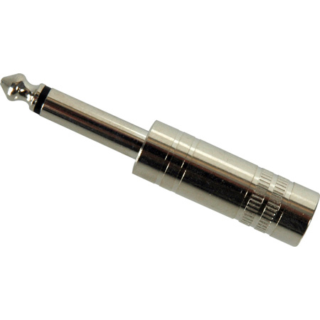

The new X-Series improves on the design of the existing phone plug by offering the thinnest available 1/4' plug with unique Neutrik chuck type strain relief on the market.
Between these two, for example
glacial spruce
Yeah, there are normally differences. This one, for instance, is a particularly nice one (and it ought to be, for nearly a sawbuck) https://www.digikey.com/en/products/detail/amphenol-sine-systems-corp/TM1RBJ-AU/10443414
 ashen sinew
I need help I have the soundboard from adafruit that connects direct to speakers. It makes a beep when frist powered but doesn't play any audio I added. It doesn't even play the test audio. Can I get a rundown on wiring and triggering? I would think I got it right based on the picture on the site but I don't know.
glacial spruce
ashen sinew
I need help I have the soundboard from adafruit that connects direct to speakers...
The learn guide covers wiring and triggering, have you looked at that? https://learn.adafruit.com/adafruit-audio-fx-sound-board/pinouts
ashen sinew
I have. that is why I don't know what I'm doing wrong. The start time works so I don't think it's the speaker. The wiring seems fine and the files are the sample ones from the guide.
 haughty dragon
Hey guys, so I went through the whole chat but there might be a thing you're missing, how do I create headphones with only 1 frequency and 1 sound in that frequency? I have bone-conduction headphones or oscillators.
glacial spruce
I'm not sure what you're asking. Only one frequency? Just a booooooop sound? That would depend on the signal source, not the headphones.
haughty dragon
okay. I want one frequency and I thought about this not needing a controller but what would it require in case I did that? 🙂
I want 40Hz while device is on
glacial spruce
Just a 40Hz oscillator
haughty dragon
okay and is that all?
cinder condor
Am I understanding right that you want the headphones to play a 40Hz tone while the device is on?
To do that, you'd need a 40Hz oscillator, and an amplifier to drive the headphones. You could build an LM386 headphone amplifier, that's a pretty simple one...
haughty dragon
Thank you @cinder condor!
harsh gust
glacial spruce
Yeah, there are normally differences. This one, for instance, is a particularly...
what do you mean by normally differences?
glacial spruce
I mean that normally different connectors will have different properties, some of which may be germane to your use case.
 torn wadi
Hey all, I've followed the Grand Central Soundboard project and want to send the audio into my computer through mic-in instead of to speakers. I had an old headset that I took the TRRS cable from and the wires that come out the other end are R+, GND, L+, MG, MC+. I feel like I would just put it through the MG and MC+, though searching around it seems like that would be too high a signal for the port on the pc. Any thoughts on how I would go about doing this?
glacial spruce
torn wadi
Hey all, I've followed the Grand Central Soundboard project and want to send the...
A simple attenuator should be able to adjust the level.
cinder condor
I eventually tracked down the distortion I was hearing trying to do I2S audio with the feather. It was a problem with the choice of clock dividers in Adafruit_ZeroI2S. I made a PR to fix it: https://github.com/adafruit/Adafruit_ZeroI2S/pull/14
GitHub
There were several problems:
Using int floor division, mckoutdiv was sometimes winding up far from the ideal value (e.g. at 48kHz, 48M/(48k*256)=3.90625, which was being floored to 3). Rounding s...
 brazen bronze
Any sggestions on great tiny speakers and mics for a watch
dusty rivet
brazen bronze
Any sggestions on great tiny speakers and mics for a watch
It won’t be cheap but here’s what Digi-Key has https://www.digikey.com/en/products/filter/speakers/156?s=N4IgjCBcoCwGxVAYygFwE4FcCmAaEA9lANrgDMAHAKwCcI%2BYMATAOwz3gxlgIC6%2BAB1RQQAZQwBLAHYBzEAF95%2BJiTEDsAQwDW2dCF7ygA
You’re looking at least $20
brazen bronze
dusty rivet
It won’t be cheap but here’s what Digi-Key has https://www.digikey.com/en/produc...
thank tou but i rhink the mic amp and speakers from adafruit will do just fune do you think they will?
dusty rivet
These are just speakers, design for small spaces like in ear headphones
You would need to provide amplification and supporting circuitry
Not sure if you’re down that path yet
brazen bronze
😅
dusty rivet
Here’s a more like.. open air speaker https://www.digikey.com/short/87fvfbd0
Cheaper too. SMD mounted, needs supporting circuitry but would be great
Honestly I might use that in my watch. Use it for alarms and sounds
brazen bronze
dusty rivet
Honestly I might use that in my watch. Use it for alarms and sounds
exactly and notifications like high or low heart rate
 bronze locust
I have two devices with Toslink output and a speaker with one Toslink input and one coax digital input. I'm looking to connect both devices to the speaker and am happy to have to flip a switch when I want to switch devices. What's the best and/or cheapest way to do this? I'm assuming it's either get a multiplexer or get a Toslink to coax converter. Looks like it's not a trivial conversion, you actually need some circuitry? [Edit: oh wait, converting to and from optical needs a converter no matter what, doesn't it]
 vale bone
A mux is going to be cheaper than a switch or a converter, but you'd have to guarantee that only one device is going to attempt to transmit at a time.
bronze locust
hm yeah. i'm looking at switches and there are a couple of mechanical ones for like $10, but i guess it's unsurprising that reviews say they tend to break
Monoprice makes a switch for $25 (https://www.monoprice.com/product?p_id=43392) and i generally trust them as a brand. Then again they also make (possibly discontinued) one of the crappy $10 mechanical switches
This Blackbird PRO Toslink® S/PDIF 4x1 Switch allows you to connect up to four Toslink digital optical S/PDIF audio source devices to a single output device, such as a television or ampl
toslink to coax converters appear to cost about the same
i guess the converter has the advantage that there would be only one input selection control (the speaker's input selection) rather than having two layers of selection
boreal pilot
Currently trying to get the best audio out of the Rp2040, would a DAC be sufficient?
Like a little integrated circuit
glacial spruce
A DAC is the usual approach, presumably you could use parallel or SPI, I'm unsure if an RP2040 can do I2S (but it may be possible via PIO).
boreal pilot
Sweet. I have an amplifier that gets me not great results but I have sound control over I2C
glacial spruce
While I2C DACs exist too, it's a kind of slow protocol and may not work well for audio.
solemn flint
There are also audio-specific chips, often called "codecs", which bundle ADCs and DACs of suitable sample rates and quality with useful stuff like headphone drivers.
boreal pilot
Interesting, okay. Because we will be driving a small speaker and a headphone jack.
Where would I find something like this?
https://www.adafruit.com/product/1712 It would run in-line with this

A mini class D with AGC and I2C control? Yes please! This incredibly small stereo amplifier is surprisingly powerful. It is able to deliver 2 x 2.8W channels into 4 ohm impedance speakers (@ ...
glacial spruce
boreal pilot
or will any DAC do the job
As in all engineering, it depends. How many I/O pins do you have free? What sampling frequency do you want? What bit depth do you want? How many channels?
boreal pilot
glacial spruce
As in all engineering, it depends. How many I/O pins do you have free? What sa...
I have a bunch of i/o pins free. Sampling frequency, as high as possible. 10 bit is okay, and just the one channel i think for now
glacial spruce
On the inexpensive and fast end, there's TI's ADC1175, capable of up to 20M samples per second with 8 bit samples. For 8 bits, it's an easy byte transfer. For more bits, it's either more parallel bits or two 8-bit fetches. There is a related 10-bit part, same speed, 10 bits, the ADC10321, Maxim also offers their MAX1426, the Analog Devices AD9200, or if you prefer a SAR architecture, the Analog AD7470
boreal pilot
glacial spruce
On the inexpensive and fast end, there's TI's ADC1175, capable of up to 20M samp...
So I ended up testing my audio with a headphone jack. It works fine, so I think I was just using a bad speaker
though there's still a slight high pitched hiss. Whats the best way to fix this?
glacial spruce
That could be amplifier noise, or digital noise coupled into the audio circuits. You might need shielding, isolation, and/or filtering to reduce it.
boreal pilot
What's the best way to find out? I dont have. an oscilloscope
glacial spruce
It tends to be an iterative, try it and see sort of approach. Try adding a capacitor to the power supply line to the amplifier and see if it improves. Try putting a grounded piece of metal between the CPU and amplifier and see if that helps, etc.
boreal pilot
Okay, gotcha. Right now it's just a breadboard and I can imagine that would cause some interference.
harsh gust

I am trying to solder and assemble this one, it's 1/4" Mono Male cable
I am not sure how I should assemble this right


is this the right way? (pretend the wires are soldered already)
glacial spruce
That looks like a nice plug. Are you asking how the wires should be attached, or how the housing should be assembled? It looks like you have the right idea, the two parts thread together to compress the inner parts to grip the wire and provide strain relief.
glacial spruce
Generally, manufacturers give some information on how to assemble their products.
harsh gust
it just came with only the components. I have tried soldering XLR cable once, long time ago
it looks a little different from it, lacking insulation pad and stuff
glad that I am going right direction haha
harsh gust
glacial spruce
That looks like a nice plug. Are you asking how the wires should be attached, o...
yeah I was wondering how to assemble those together
ok nice
and for soldering, Tip goes with the center, and Ground goes with the outer one, right?
glacial spruce
Often the documentation is available on the manufacturer's site, and you can look it up by the part number.
Yes, the center cup is the tip contact, and the outer one is the other ("sleeve").
harsh gust
Ok I did it and tested it out, it works perfectly fine

but I don't think that's soldered well.
and it took me so much time soldering that one thing, which shouldn't really take this long...
I am using this solder that I got from All Electronics

and I use this cheap soldering iron I got from amazon years ago.


Do you think that I need to upgrade my gear? or it's just me not good at it yet? 😮💨
It wasn't like this before but today, the solder was like dry clay, falling apart, quickly dry out in the air and just drop on the table, messy, not attaching on the surface at all, etc
it was really hard to do anything but I don't know if it's me, or the iron or the solder
terse maple
if it's the piezo element you're trying to solder to, it's basically a heat sink, so will be challenging to solder to directly. there's a reason they're connected using spring contacts in a lot of manufactured electronics
glacial spruce
Solder can do that if the iron temperature is too high or too low, and/or if there's insufficient flux. Note that flux burns off as you solder, so if you're taking a while to make a joint, the flux will all get used up. Flux is magic, it makes everything better.
harsh gust
ahhhh
random bone
harsh gust
ahhhh
if you buy flux, make sure you buy flux designated for electronics soldering. hardware store flux for plumbing is acidic and will eat up your connections. (zinc chloride flux is bad)
glacial spruce
Additionally, buy flux that's compatible with your solder (lead free solder uses different flux than leaded solder)
harsh gust
ahhh thank you so much!!!!
random bone
Leaded solder is a lot easier to use, but it's your decision about what to use. Lead-free solder that has silver in it is generally easier than not. Also the solder should have a flux core, not just be solid solder without flux. The solder I see in tubes at AllElectronics looks like regular leaded solder with a flux core, but you can confirm based on your order.
dull basalt
we always used Kester (Brand) 60/40 iirc.
harsh gust
ahhh thank you! I will try kester 60/40
harsh gust


I am doing it at school and it works so well!! I think it's my solder and my soldering iron 😮💨😮💨
azure panther
That is a fairly nice iron
harsh gust
oh is it? how much is it lemme google this model real quick
azure panther
It's like an entry level nice iron. I have one. I love it
azure panther
Yeah it's not cheap
 broken falcon
Anyone aware of a tutorial for DAC (M0) audio out for Feathers using Arduino? It's straightforward with CP and audioio, but I cannot use CP for other parts of my application. I'm using a Huzzah32.
glacial spruce
I don't think a Huzzah has an M0?
dusty rivet
glacial spruce
I don't think a Huzzah has an M0?
I don’t see any in the shop
glacial spruce
To be more specific, I thought the Huzzah board was ESP32 based, not SAMD (M0) based
broken falcon
Sorry, typo on my part. I meant The analog out pin (A0) as opposed to I2S.
I came across this library, which might do what I need. https://github.com/pschatzmann/arduino-audio-tools
GitHub
Arduino Audio Tools (Music Player, Music Recorder supporting I2S, Microphones, DAC, ADC, A2DP, Url, MP3, AAC, AudioKit, ES8388) - GitHub - pschatzmann/arduino-audio-tools: Arduino Audio Tools (Musi...
whole smelt
Hi all, trying to run a basic PDM mic example using an ESP32-S2.
samples = array.array('H', [0] * 160)
But I get NotImplementedError: PDMIn not available.
Is this because it's unsupported on Espressif platforms? If so, are there any workarounds for reading microphones?
boreal pilot
Hey folks, I bought one of these to play audio for my project but I cant seem to figure out where to find the right code.

Currently it's hooked up to my RP2040 via I2C
terse maple
boreal pilot
Hey folks, I bought one of these to play audio for my project but I cant seem to...
are you sure that's the right screenshot? a thermocouple amplifier is for measuring temperature, not playing audio
boreal pilot
I bought the wrong component then. Lol

I also bought this but there doesn’t seem to be circuit python intergration
terse maple
i think i saw a CircuitPython module for it, but there was a warning that it doesn't play audio files because CircuitPython can't move the bits around fast enough (yet)
boreal pilot
Oh sweet
So I’m out of options for playing sound through my RP2040

Unless I get one of these?
odd oasis
boreal pilot
I also bought this but there doesn’t seem to be circuit python intergration
If you just need to play audio from a few files, this could work.
boreal pilot
its like, toy sound effects.
odd oasis
Oh then you should be able to store the effects on a micro SD card and use the rp2040 to command which file
boreal pilot
To the Codec breakout?
odd oasis
I believe that’s how that one works, anyways
boreal pilot
I got audio working with a separate Amp
just using Audio over PWM
But theres still this high pitch wheezing that I cant seem to solve,.
terse maple
yeah, that breakout isn't set up to directly read files from SD. it relies on the microcontroller to shuffle bits between the SD and the codec chip
odd oasis
Yeah, if you need better sound quality https://learn.adafruit.com/mp3-playback-rp2040/pico-i2s-mp3 is the way to go
 boreal pilot
it just needs to work for now
boreal pilot
terse maple
yeah, that breakout isn't set up to directly read files from SD. it relies on th...
Yikes
odd oasis
PWM inherently has very high frequencies that could be filtered out with a well-designed low-pass filter, but I2S is probably easier.
boreal pilot
Yeah unfortunately I ordered the wrong parts
odd oasis
If you have any resistors and capacitors, you could try filtering the PWM output? https://www.allaboutcircuits.com/technical-articles/low-pass-filter-a-pwm-signal-into-an-analog-voltage/
In this article we will take a closer look at how to effectively low-pass filter a PWM signal into an analog voltage.
boreal pilot
This article just talks about voltages
boreal pilot
Made some progress. i made a low pass filter but now my overall volume is very low.

Here’s what it’s looking like so far.
dull basalt
Hey, could anyone please help me with STEMMA Speaker, I have it connect it to Flora . Could someone tell me please how to enable the speaker and which library to use? Would simple Arduino Tone Library work? Can anyone help me with the code, I just need a quick example. 🙂
 lime yew
dull basalt
Hey, could anyone please help me with STEMMA Speaker, I have it connect it to ...
lime yew
dull basalt
Hey, could anyone please help me with STEMMA Speaker, I have it connect it to ...
Have you had a look at the guide? How far have you gotten? https://learn.adafruit.com/adafruit-stemma-speaker

Adafruit Learning System
Have you heard the good news? It's a STEMMA Speaker!
dull basalt
lime yew
Have you had a look at the guide? How far have you gotten? https://learn.adafrui...
I did go throught the guide. What I don't understand is how do I enable it for Flora? Can I use the CircuitPlayground Library? I am absolute newbie, so the guide only raised more questions then answers. 🙂
lime yew
dull basalt
I did go throught the guide. What I don't understand is how do I enable it for F...
Yeah the guide is assuming you're using a board running CircuitPython the Flora doesn't so yes you would program it in Arduino and use the tone library or similar to drive it
 tacit oasis
Hello everyone, can we play audio in stéréo with 2 I2S, and in the same time displaying images et using analogiques calculation ? (in Esp32-S3)
It needs multitasking, I tried Asyncio( ), to gather Sound audio and display and calculation, but looks like the sound doesn't want to play in the same time with the others interactions
I dont know if this is too much for the program or the Esp32
odd oasis
tacit oasis
It needs multitasking, I tried Asyncio( ), to gather Sound audio and display and...
Esp32 with circuitpython should be able to play i2s audio in the background while other tasks are running. Could you post your code?
Not sure how much calculation you’re doing or how much display updating you’re doing, but if the overhead of the python interpreter is slowing things down, you may instead have more success transitioning to arduino or ESP-IDF.
tacit oasis
I am using CircuitPython beaause of : audiomixer and audiocore
My main code is:
it's linked with 3 other files, one for the sound, the other for a matrice and the last for the screen
To see in the screen le pressures above à matrice surface (I can take a picture if you want)
Here the three others files:
tacit oasis
odd oasis
Not sure how much calculation you’re doing or how much display updating you’re d...
Only one display and à multiplexeur with analogique input
The main files is for creating the tasks, the matrice one for analog input to localisé pressures , and the screen one for a display to show the pressures on the matrice
odd oasis
“while Mixer.playing:
pass”
Is blocking your code in your play_Ambiance() function, it seems.
tacit oasis
I tried "while Player.playing" too, why do you think it will block?
odd oasis
tacit oasis
I tried "while Player.playing" too, why do you think it will block?
Namely, the “pass” keyword prevents any other async function from running until the while condition becomes false. Essentially, this means until your Mixer or Player is done playing whatever file or sample it’s playing, none of your other code will run.
In this case, I would try commenting out the while loop entirely and see what it does.
tacit oasis
No sounds comes out, I will try to see if others interactions work then.
How can I continuously read audio files with others interactions without a while loop : and pass?
odd oasis
Hm, might be worth checking out #help-with-circuitpython for that. I know AudioOut.play(audio mixer) is non-blocking, so if no sound is playing, you may have some issue with your setup somewhere else. I haven’t tried using it with asyncio so I’m afraid I can’t help much more than that…
tacit oasis
Thank you Hem, ok I am gonna to check with help-CircuitPython 😊
 round birch
@dull basalt
I have that speaker. It's just an audio amp as far as I can tell. STEMMA is a misnomer as the interconnect has only three pins. It suits my needs but is power hungry.
odd oasis
round birch
<@456226577798135808>
I have that speaker. It's just an audio amp as far as I c...
Stemma should not be mistaken for Stemma QT. They have different connectors, and only the latter is designed specifically for I2C.
round birch
@odd oasis
The devil is in the details.
 inner lava
hello!
anyone here played with moodbar?
I'm trying to get it output only 28 segments, so to fit it on a LEDShim, but can't find the code section where it states the number of samples 😅
inner lava
managed!
for future reference, open src/moodbar/moodbarpipeline.cpp, replace 1000 with your value of choice and you're golden!
FYI, result when ran against Oxygène Part IV
 harsh gust

alright now I gotta mount this circuit into the aluminum enclosure
what would be the best secure way to do ittt
glacial spruce
As always, "best" depends on what your parameters are. A low effort and very secure way is to pot it in a liquid that hardens, fixing it firmly in place. However that's messy and makes it difficult if you ever need to repair it. A quick and easy way is stick it in place with foam tape. The traditional approach is to drill holes and use standoffs to screw it in place. Other possibilities include hook-and-loop fasteners, clips, guides, an internal framework, replacing the lid with a front panel with everything attached, foam, board edge supports, and many others.
queen cradle
Whatever you do, just make sure there’s a gap or insulation between the board and the case. I recommend insulation, even if there’s a gap, just in case something conductive gets between the board and case
harsh gust
maybe buying one of these and attach both on the enclosure and the circuit, and then attach em together to hold it tight?
 harsh gust
also, this is the test recording of the piezo mic.

This is the screenshot of previous answer by @glacial spruce, I am sure it's not mechanical coupling

I tested out like this
that is a ant nest built with hydrostone gypsum cement, piezo mics are built inside of it
so it's piezo mic -> amp circuit -> zoom h4n pro
 minor girder
hello
i need help finding a bluetooth board with amp output listed in the specs?
like this

MakerHawk 2pcs Bluetooth Audio Receiver Board BT 5.0 Stereo Audio Amplifier 3.7-5V Car Speaker Amplifier for DIY
orrr can i put an transistor bewtween a 2.5W amp and a 1W speaker
minor girder
if i can find a 1W amp
for my one 1W speaker
and a 2W amp for my bone headphones
no such thing as a dual amp with 1amp and 2 amp
lol
glacial spruce
The wattage doesn't have to match exactly, they're just maxima. So you could use a 3W stereo amplifier to drive a speaker and at least one of your bone transducers, depending on the transducer impedance and what the amplifier supports, you might be able to drive both of them (with the same signal). If you want 3 separate signals, you'd need 3 separate amplifiers, but it could be one monaural one and one stereo one.
minor girder
i want the speakers to be connected to my mic for my voice seprate audio than the music
glacial spruce
So music (via bluetooth?) to one (or two?) speakers (or transducers?), and voice (via analog?) to a (different?) speaker?
boreal pilot
https://learn.adafruit.com/adafruit-max98357-i2s-class-d-mono-amp/circuitpython-wiring-test Would this work with Feather RP2040?

Adafruit Learning System
Add digital-quality audio with a class D amplifier for easy sound!
 plush temple
boreal pilot
https://learn.adafruit.com/adafruit-max98357-i2s-class-d-mono-amp/circuitpython-...
plush temple
boreal pilot
https://learn.adafruit.com/adafruit-max98357-i2s-class-d-mono-amp/circuitpython-...
yes, I'm working with it on a RP2040
boreal pilot
Oh sweet
boreal pilot
plush temple
yes, I'm working with it on a RP2040
What does your pinout look like?
plush temple
boreal pilot
What does your pinout look like?
audio_out = audiobusio.I2SOut(board.A1, board.A2, board.A0, left_justified=False)
boreal pilot
Sweet, okay. thanks dude!
plush temple
np
tall mango
if im gonna connect a bare condenser microphone module to my PC's microphone port does it need a mic pre amp or does the PC not need it?
I know for example a turntable needs a pre amp to connect to a speaker, but im wondering if said speaker (in this case PC) has that pre amp built in
 gritty brook
Hi everyone, I'm getting into embedded audio and trying to understand this codec's datasheet. One of the things that confuses me is Standalone vs Software mode. Are they exclusive, or should I / can I use both? As far as I can see Standalone mode allows to set certain configuration options by pulling one of the pins up or down. Software mode allows to send configuration bits via i2c or spi.
Is it basically you either want a less configuration-and-pin-use-heavy standalone mode withe less options or more configuration & more configuration options software mode?
https://statics.cirrus.com/pubs/proDatasheet/CS4270_DS686F2.pdf
glacial spruce
tall mango
if im gonna connect a bare condenser microphone module to my PC's microphone por...
It depends on the condenser mic module. There are several kinds, with differing requirements and capabilities.