#general-chat
1 messages · Page 54 of 1
 fossil dawn
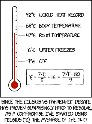
The symbol for degrees Felsius is an average of the Euro symbol (€) and the Greek lunate epsilon (ϵ).
 steel sequoia
Apologies if general is not the correct channel to ask but none of the other seemed appropriate either;
Are there any routes for bulk ordering of products such as the neopixels? The largest sizes I'm able to find usually range in between 10 and 100 pieces where I think for the project I might need around to more than 600 per and I'm trying to build 5 
 sick apex
what is an 8bit shift register
74hc595n hyc2125z
i have one of these but idk what it does
steel sequoia
Ah it's a bit like a conveyor belt on which you can keep putting bits; though it's better to take this to one of the help channels
 fair summit
local restaurant:
 sick apex
and what about a 4N35, i got one of those too
sick apex
steel sequoia
Ah it's a bit like a conveyor belt on which you can keep putting bits; though it...
ill read the data sheet
steel sequoia
Basically, you can send bits one at a time until you have 8 in there, shifting all of them over one bit per new one, then output all of them at the same time
sick apex
steel sequoia
Basically, you can send bits one at a time until you have 8 in there, shifting a...
alr
steel sequoia
4n35 sounds like an optocopler, that right?
sick apex
it says that, what are they
steel sequoia
Optical coupler, you can think of it like a relay that fully disconnects two things;
On one side something like a light and the other a solar panel, so when one side is on the other will let current through
It's useful for making sure certain parts are fully isolated, but has different uses (mostly between high voltage controlled by low voltage) because running like 400v through a processor isn't a good idea 
sick apex

so i could use it to turn on a 12 v light
with a micro controller
or something
without frying it
steel sequoia
Yeah, though that depends on the specs the optocoupler, but you shouldn't fry your microcontroller yep lol
steel sequoia
They do but that keeps them in the same circuit, so if something happens with the thing that turns on suddenly you can have that power flowing through your microcontroller
sick apex
ohhh right
steel sequoia
It's similar in use, but keeps the signals/electricity of the two things fully isolated, you can think of it like a relay
sick apex
so the octopus thing doesn't let you blow everything up
but the transistor would let you
got it
steel sequoia
Yep
 sick apex
fr
 dusty citrus
Ah may be dumb but I don't get it
I got 5 vlan
1 vlan default I want to edit it's ip but I can't
I was told to connect through another vlan
Like the 8 vlan X ip 10.10.98.1 like in port 10
Done can't connect to the switch dashboard
(so I can edit the default vlan)
 late fulcrum
In some routers, you can't edit the VLAN you're on, as it would disconnect you
dusty citrus
late fulcrum
In some routers, you can't edit the VLAN you're on, as it would disconnect you
In this case it's a switcg aruba ion 1690 ; I thought that it was not possible too, but I was told that I was wrong idk
 rapid geode
 dusty citrus
Yuk too much cheese
 raw jasper
rapid geode
raw jasper
rapid geode
enjoy!
rapid geode
dusty citrus
Yuk too much cheese
you are dead to me
actually has fairly little cheese
compared to say, pizza hut etc
dusty citrus
Fun fact I sometime discard cheese from bought pizza
dusty citrus
I also do lol
Anyhow you should try some "focaccia Recco" if you like cheese
 rapid geode
i made a stuffed crust pizza once


 pale veldt
Anybody here with apps script experience?
 rain cradle
pale veldt
rain cradle
<https://dontasktoask.com/>
rain cradle
pale veldt
rain cradle
<https://dontasktoask.com/>
my B
Its a very stupid problem,
basically a part of my code is
var value=ss.getRange(1,2).getValue();
if(value ='1'){
ss.getRange(1,2)
Browser.msgBox('Congrats you are level 1!')
But the variable value turns grey as apps script is not being able to recognise that the variable is in use. How do i solve this?
 glad ruin
Not sure if this is the case with JavaScript, but it looks like you are assigning value = '1' in the if statement rather than comparing for equality.
pale veldt
I want to basically get a cell (Which will depend on a dropdown) value and then compare if that value is 1 or 2,
pale veldt
glad ruin
Not sure if this is the case with JavaScript, but it looks like you are assignin...
how do i compare? i come from Bluej hence i used if like this.
glad ruin
rain cradle
double equals is funny
Yeah I know JS does some Weird Things™️ with type conversions and comparison operators.
glad ruin
pale veldt
how do i compare? i come from Bluej hence i used if like this.
I don't know JS, I just know that it has some very odd rules.
pale veldt
I used <= and now it works fine
rain cradle
FYI equality is usually ==
 urban arrow
Needed a way to find the count of dicts inside a list - which is normally how a json file is formatted, like when I download from AdafruitIO. Came across this: magical.
DICT_COUNT = len([ele for ele in data if isinstance(ele, dict)])
data is the name of the object I loaded the json file into (json.load) .
Still learning every day 🙂
rain cradle
could also use filter, not as readable in this usecase, but would be better on other scenarios len(list(filter(lambda x: isinstance(x, dict), data)))
filter returns a generator, so you need to convert it into a list ("consume" it) to be able to check its length
urban arrow
cool, thanks.
 tardy badger
Me at work last week: “ah yes, enough work to keep me busy”
Me today after a meeting:

Basically got told that a firehouse has been turned on and they want the work yesterday lol
tardy badger
Lol I’d most assuredly end up under federal investigation if I tried lol
rapid geode
yes, but the investigators are using chat gpt
 brittle condor
does anyone know any info about these microbuttons that ipads use for their volume buttons?
i'm trying to find the single component because the part it self it's either hard to find or too expensive...

 violet parcel
wow cooking simulator graphics from the screenshots above are really good
tardy badger
brittle condor
does anyone know any info about these microbuttons that ipads use for their volu...
They tend to be similar to these https://www.digikey.com/en/products/detail/EVP-BB4A9B000/6212410
You likely won’t get the exact part number though
violet parcel
tardy badger
They tend to be similar to these https://www.digikey.com/en/products/detail/EVP-...
there is plenty of the whole thing at 2$ on aliexpress not sure what is the problem here exactly I feel like there is more to this question since the aliexpress results were very easy to find
tardy badger
They’re asking about the buttons specifically, not the assembly
Apple very often will use proprietary buttons because it’s cheap to custom order them if you want to buy 500 million of them
violet parcel
just cut them it's just 2$... and they said the whole part itself is hard to find or too expensive. I doubt 2$ is too expensive or aliexpress is hard to find
so my understanding is that they prefered to find the whole part but they will now settle for the buttons
fossil dawn
🔮
brittle condor
violet parcel
just cut them it's just 2$... and they said the whole part itself is hard to fin...
I was trying to get faster shipping than AliExpress... I can't find the part within europe...
brittle condor
tardy badger
They tend to be similar to these https://www.digikey.com/en/products/detail/EVP-...
Thanks!
fair summit
brittle condor
Thanks!
ifixit has the button assemblies in their European store for 15-20 euros: https://eustore.ifixit.com/
brittle condor
Didn't know they had an europe specific store, thanks!
violet parcel
I dont know where you are in Europe but are they walking the part to europe to spend 1 month on shipping ?
when they ship something to me in canada takes 1 day to get to canada and 2-3 months to marinate at the customs
violet parcel
no
 solar flicker
Oh
fair summit
there are analogs for much of MicroPython's functionality (machine, etc.)` in CircuitPython, but the API is different
violet parcel
but it could be close enough if you dont have any other code for a chip/component. But micropython is actually a mostly full python. Circuitpython is a custom version of python in a way because of a custom API much more centered on electronics (AFAIK as I knew one year-ago)
solar flicker
Let's say I got a code like this:
import network
import socket
from machine import Pin
from time import sleep

wlanLed=Pin(5,Pin.OUT)

wlanAdapter=network.WLAN(network.STA_IF)
wlanAdapter.active(True)
powerLed.on()


wlanAdapter.connect("someAP","somePass")

while wlanAdapter.isconnected()==False:
    wlanLed.toggle()
    sleep(0.5)

wlanLed.on()  ```
Will it work with CircuitPython?disclaimer: as far as I knew / 1 year ago
@solar flicker Id ask in #help-with-circuitpython tell them you want to convert this micropython program to circuitpython and if it is possible
brittle condor
violet parcel
when they ship something to me in canada takes 1 day to get to canada and 2-3 mo...
from china, at least with aliexpres it takes just 10 days usually...
from the uk, i had mixed experiences, once ordered from pimoroni and had no issue, came withing the week, others it took months...
from australia, i only had one package from a friend, it took months and i completely forgot that it was shipped
from the rest of the world, no idea...
late fulcrum
brittle condor
does anyone know any info about these microbuttons that ipads use for their volu...
Those are generally implemented in 3 pieces: there's the traces/contacts which are part of the underlying PCB, then the dome that implements the switching action like https://www.snaptron.com/products/standard-domes/, then polyimide tape to hold the domes in place.
brittle condor
i know what you mean, but those are an all in one component which gets soldered on the pcb
 torpid jungle
Out of curiosity; Is there a logic IC existing that can do comparison of multiple PWM signals and output the lowest to the output pin? Or is that IC now something like Atmega or other MCU?
glad ruin
Are these signals synchronized?
torpid jungle
glad ruin
Are these signals synchronized?
Unfortunately not 
E.g.; they are Tacho signals which I would like to see which is the lowest.
 glacial wigeon
some MCU's like the rp2040, can measure the pulse width of 2 (maybe more?) pwm signals in hardware, and report that to software
then you can just average a few pulses, and decide
torpid jungle
Oh, I know, I've got Pico board coming up as a fan controller but I was thinking that am I able to achieve the comparison without MCU
glacial wigeon
you could also just run the PWM signals thru a low-pass filter, turning them into analog
and then use an opamp to compare them
 glacial wigeon
something ive thought about, with regular old servos
what if, in the old says, the PWM signal was just low-pass'd
and then opamp compared, to a pot
and the result, drove the motor
and boom, servo!
solar flicker
I have a question
Whenever we plug in pico to laptop while holding bootsel button, it shows 127 mb of free space. Then why it shows 800 kb in thonny as all space?
glacial wigeon
solar flicker
I have a question
Whenever we plug in pico to laptop while holding bootsel butto...
that 128mb drive, is entirely unrelated to the available flash space
that is just for accepting UF2 files
solar flicker
Uhm...
Then it means most of the 128 mb is took by uf2 file?
glacial wigeon
no
the uf2 file is not actually stored as-is
each 512 byte block of the uf2 file, contains 256 bytes of data, and a command
as you try to copy the file in, the bootrom will interpret those commands, and program 256 byte chunks to the onboard flash
the pico only has 2mb of flash in total
glacial wigeon
the rp2040 chip supports a max of 16mb of flash
so the largest valid uf2 file would be about 32mb
the fake disk drive is 128, just to give some extra room
solar flicker
I am having trouble with installing adafruit pip package. where should I talk about it?
here? or in other channel?
 ancient rivet
solar flicker
I am having trouble with installing adafruit pip package. where should I talk ab...
ancient rivet
solar flicker
I am having trouble with installing adafruit pip package. where should I talk ab...
guessing these are circuitpython libraries? try #help-with-circuitpython
solar flicker
ancient rivet
guessing these are circuitpython libraries? try <#537365702651150357>
yep
Alright,moving there
 velvet minnow
hello! anyone have experience or know anyone who has experience with schematic/pcb design?
fair summit
velvet minnow
hello! anyone have experience or know anyone who has experience with schematic/p...
ask your q in #help-with-hw-design
velvet minnow
fair summit
ask your q in <#656770973852237844>
thanks!
late fulcrum
glacial wigeon
and boom, servo!
That's pretty much what the chips in servos do
 glacial wigeon
ah, so while the specs may claim a required freq and pulse length
its just analog
glad ruin
Most hobby servos are just analog, yes.
late fulcrum
Depends on the servo, but yes, some are just simple analog circuitry
 zinc pier
Hi all, i need some advice, i have a Adafruit 16-Channel PWM/Servo HAT, on an RPI, the basic plan is to have it control a servo to open an iris and then turn on a fan. I have managed to get the servo working, but I am at a loss on what to do for the fan. When i connect the Noctua fan (3pin) to the hat, the fan starts straight and I have no control. Any suggestions?
glad ruin
3-pin fans aren't the same as servos. They have power, ground, and a tachometer output.
 south light
Yep, speed controllable fans have a 4th pin
And fans don't take nicely to just trying to PWM their supply voltage either
urban arrow
OK guys, I know... I used to fly (still do just not as often) RC helicopters, and have several servos lying about. They're pretty hi-voltage tolerant designed for heli/airplanes. Could you point me to a good beginner guide? I don't have a "servo" controller board per se. Just want to get started experimenting. Do I need a breakout? Or working with a breadboard OK? Thanks.
south light
zinc pier
Hi all, i need some advice, i have a Adafruit 16-Channel PWM/Servo HAT, on an RP...
do you actually need to control the speed or is just on/off allowable? If it is allowable, you could use a mosfet to cut power to the fan
south light
urban arrow
OK guys, I know... I used to fly (still do just not as often) RC helicopters, an...
Positive power to servo vcc, ground to ground, mcu ground to servo ground, most mcus can drive a servo from a GPIO. Just gotta be careful to not connect the servos power direct to the mcu
zinc pier
So what would be the best way to control a fan, don't actually need speed control (it would be nice but not a deal breaker) but i do need to shut it down.
late fulcrum
Probably just a transistor to switch the power on and off.
fossil dawn
Even those 3-Pin PC fans are speed controllable. But I think they are controlled by adjusting the voltage
glad ruin
The third pin is the tachometer, which is used to measure the speed.
fossil dawn
yes exactly. But I think you control the speed by varying the voltage of the positive wire
 unkempt hearth
By some minor miracle, it appears that the Adafruit Powerboost 1000 is back in stock. I am not well versed in power circuits, but when I use this module do I need a battery circuit protector (DW01) when using a 18650 type cell, or are the protections provided in the MCP73871 module sufficient? Also, not excited to see the Micro-B connector, but can I use a Type-C breakout connected to USB/Gnd? I assume the MicroB data pins aren't really being used.
south light
fossil dawn
yes exactly. But I think you control the speed by varying the voltage of the pos...
yes, though with limited nonlinear control, and building such a circuit controllable from an arduino is accordingly a bit of a pain in the butt
PWM'ing a voltage tends to just reset the BLDC controller repeatedly rather than limiting voltage. So you have to filter it
At which point, easier to just buy 4 pin fans
late fulcrum
unkempt hearth
By some minor miracle, it appears that the Adafruit Powerboost 1000 is back in s...
The charger module will protect against overcharging, but the boost unit won't protect against short circuits or overdischarging. The data leads aren't used, so any way to feed it 5V will work.
sick apex
raw jasper
Oh you've actually got it working?
yes but at like
4 bytes per second
max
and i also haven't added any parity yet
i managed to get around 26 bits per second
when i set the bitrate to 32 bits per second
im gunna up it to 64 then check if it gets faster
fossil dawn
what are you using to transmit between them?
Software bitbanging? Or some SPI, I2C, other stuff?
 night crescent
WE ARE LIVE! ASK AN ENGINEER! https://youtu.be/6bGPyMwcw50

ASK AN ENGINEER 7/19/2023 LIVE!
Visit the Adafruit shop online - http://www.adafruit.com
LIVE CHAT IS HERE! http://adafru.it/discord
Adafruit on Instagram: https://www.instagram.com/adafruit
Subscribe to Adafruit on YouTube: http://adafru.it/subscribe
New tutorials on the Adafruit Learning System: h...
sick apex
fossil dawn
what are you using to transmit between them?
Software bitbanging? Or some SPI, I...
im making my own transfer protocol
lmao
fossil dawn
i see 👍 very interesting
sick apex
yes
fossil dawn
but I bet you can optimize it further if you use some hardware for it
sick apex
probably, i mean im generating a clock on the host board
so if i used a crystal oscilator or something it would probably be faster
i think im gunna use another one of my boards to generate a clock
to see if i can make it faster like that
only issue is that i dont have an oscilator on hand
fossil dawn
RP2040 pio would be perfect for this I think 🤔
fossil dawn
I haven't even started to look at PIO assembly. lmao
sick apex
but i dont know how to set a delay and i need to be able to control the speed
so i can test during the parity phase
so i can inject a bit flip
night crescent
10% discount code, code is: portalpower http://www.adafruit.com ends at midnight NYC time
Adafruit Industries, Unique & fun DIY electronics and kits : - Tools Gift Certificates Arduino Cables Sensors LEDs Books Breakout Boards Power EL Wire/Tape/Panel Components & Parts LCDs & Displays Wearables Prototyping Raspberry Pi Wireless Young Engineers 3D printing NeoPixels Kits & Projects Robotics & CNC Accessories Cosplay/Costuming Hallow...
glad ruin

Now you're thinking with Portals
https://images-ext-2.discordapp.net/external/pRlj50_2FoXpY5MpLcsjYCnEdHqXrIoQmpzMNE3Sc-U/https/i.imgur.com/Bq0GsOz.mp4
 sick apex
fossil dawn
I haven't even started to look at PIO assembly. lmao
sick apex
fossil dawn
I haven't even started to look at PIO assembly. lmao
i know basic x86 assembly and how to use it
i know the instructions are different but they shouldn't be too dissimilar that i cant figure it out
fossil dawn
wow
glad ruin
They are completely different, but far simpler.
sick apex
yeah i know i've seen some
fossil dawn
I only knew the assembly for the 4bit, 32byte memory mcu we programmed in class in VHDL 😆
sick apex
i mainly just use asm in my c++ projects to perform maths slightly quicker
glad ruin
The PIO is a special-purpose processor. Actually it's not really even a full processor, just a programmable state machine.
sick apex
glad ruin
The PIO is a special-purpose processor. Actually it's not really even a full pro...
which i could in theory use to generate a clock pulse right?
fossil dawn
sick apex
which i could in theory use to generate a clock pulse right?
of course yes
glad ruin
Yeah
sick apex
lemme just record a video rq
glad ruin
Although you'd probably be better off using a timer for that.
fossil dawn
For example PIO is used to create I2S in earlephilhower/arduino-pico. And I2S has Bitclock, left-right-clock, and signal. All generated using PIO I think
sick apex
this is as fast as I can get it so far
set with my bitrate being 128 in code
so the clock im generating is set at 128 times per second
its only managing about 26 bits per second
im gunna spin off the data receive onto the other core
and see if i can make it any faster like that
late fulcrum
sick apex
but i dont know how to set a delay and i need to be able to control the speed
There's a useful video on it: https://www.youtube.com/watch?v=oLYLnb7kpLg
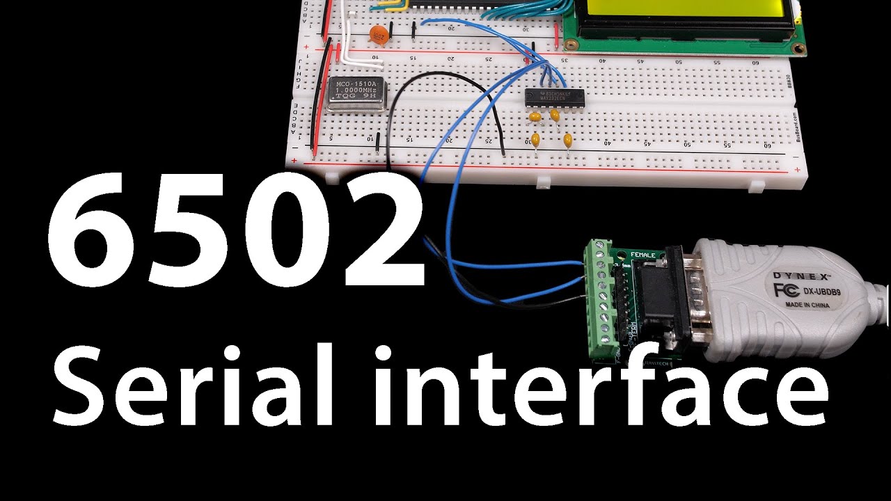
Support these videos on Patreon: https://www.patreon.com/beneater or https://eater.net/support for other ways to support.
Social media:
Website: https://www.eater.net
Twitter: https://twitter.com/ben_eater
Patreon: https://patreon.com/beneater
Reddit: https://www.reddit.com/r/beneater
Special thanks to these suppo...
sick apex
late fulcrum
There's a useful video on it: https://www.youtube.com/watch?v=oLYLnb7kpLg
seen it, doesn't exactly apply to what im trying to do
i thought it would but it didn't
thank you anyways
Core  0 register dump:
PC      : 0x4008b05b  PS      : 0x00060036  A0      : 0x80089bec  A1      : 0x3ffb91f0
A2      : 0x3ffbf398  A3      : 0xb33fffff  A4      : 0x0000abab  A5      : 0x00060023
A6      : 0x00060023  A7      : 0x0000cdcd  A8      : 0xb33fffff  A9      : 0xffffffff
A10     : 0x3ffbf384  A11     : 0x00000001  A12     : 0x00060021  A13     : 0x3ffb92d0
A14     : 0x007bf398  A15     : 0x003fffff  SAR     : 0x00000000  EXCCAUSE: 0x00000001
EXCVADDR: 0x00000000  LBEG    : 0x40086108  LEND    : 0x4008611e  LCOUNT  : 0x00000000


Backtrace: 0x4008b058:0x3ffb91f0 0x40089be9:0x3ffb9230 0x400884ac:0x3ffb9260 0x4008845c:0xa5a5a5a5 |<-CORRUPTED
the joys of trying to use the other core
late fulcrum
Multi core is hard
sick apex
late fulcrum
Multi core is hard
i change my approach
im gunna make 2 tasks
a core 0 loop
and a core 1 loop
core 0 loop will handle the clock and sending the data
core 1 loop will handle updating the OLED display
which means i dont need to spend so much time talking to the OLED display on whilst trying to send data
hopefully i can gain a few bytes per second
then its upto the clock speed
sick apex
late fulcrum
Multi core is hard
you see anything wrong there?
wait one second
there
Guru Meditation Error: Core  0 panic'ed (Unhandled debug exception).
Debug exception reason: Stack canary watchpoint triggered (IDLE)
Core  0 register dump:
PC      : 0x40089d8d  PS      : 0x00060036  A0      : 0x400884af  A1      : 0x3ffb9210
A2      : 0x3ffc2c7c  A3      : 0x3ffc2e70  A4      : 0x3ffc2e70  A5      : 0x00000001
A6      : 0x00000000  A7      : 0x00000000  A8      : 0x3ffc2c84  A9      : 0x3ffb91f0
A10     : 0x3ffbc8d8  A11     : 0x3ffbc8d8  A12     : 0x00000014  A13     : 0x00000000
A14     : 0x3ffbc8d0  A15     : 0x80000001  SAR     : 0x00000000  EXCCAUSE: 0x00000001
EXCVADDR: 0x00000000  LBEG    : 0x40086108  LEND    : 0x4008611e  LCOUNT  : 0x00000000


Backtrace: 0x40089d8a:0x3ffb9210 0x400884ac:0x3ffb9240 0x4008845c:0xa5a5a5a5 |<-CORRUPTED```that's what i get
ohhhhhhhh i haven't linked the memory
im smart i promise
 ebon dew
seem pretty dang smart to me. if you're in kernel panic land you're pretty advanced in my eyes.
sick apex
ebon dew
seem pretty dang smart to me. if you're in kernel panic land you're pretty adva...
lmao fair enough
handling memory from one core to another isn't very fun when there isn't an operating system to do it for me
ebon dew
You're probably limited to the clock speed of the little displays which for SPI is about 33.3mhz in circuit python for most boards. Like.. there is a speed limit.
sick apex
ebon dew
You're probably limited to the clock speed of the little displays which for SPI ...
nah, im outputting the bits through an LED aswell and its only flashing at like 26 hz
well flashing / not flashing
but i have another one linked up in reverse
so when its a 0 one turns on
if its a 1 then the other turns on
ebon dew
and if you were using I2C you'd likely hit half that speed since I2C is half duplex and SPI is full duplex. Only way to go faster is parallel/PIO state machine. There are ways but that kind of thing is way over my head.
maybe i meant Hz and not Mhz.
sick apex
ebon dew
and if you were using I2C you'd likely hit half that speed since I2C is half dup...
im using I2C for the OLED
ebon dew
It's been a while since I attempted overclocking... got it up to about 2x before it starts artifacting so 33.3x2 = 66.6
sick apex
but the LED only runs at like 26 hz
late fulcrum
I2C is inherently slower, it often runs at 100kHz or 400kHz, whereas SPI is generally well up in the megahertz
late fulcrum
I'm wondering why your LED is 26Hz. Even a 1MHz CPU should be able to go significantly faster than that
sick apex
late fulcrum
I'm wondering why your LED is 26Hz. Even a 1MHz CPU should be able to go signif...
its a 240hz processor
like i set the clock speed for the output to be around 1khz
and it still didn't work
im switching it over to multi core, once that's sorted i'll lyk what happens
late fulcrum
when you say "set the clock speed for the output", what are you referring to?
ebon dew
yup then you'll hit a 33.3 Mhz barrier with I2C. i think the limitation is part of the protocol more than the board.
sick apex
late fulcrum
when you say "set the clock speed for the output", what are you referring to?
the host device generates a clock speed that signals to the target device to interrupt and read data from the data pins
ebon dew
I have yet to try with a Metro iMX, I bet they're fast. 😉
sick apex
i know the clock speed is getting higher because the led i linked to the clock speed flashes faster
but the data wont go any quicker
late fulcrum
It sounds like you're not directly controlling the LED, but sending info to something that then turns the LED on or off?
sick apex
late fulcrum
It sounds like you're not directly controlling the LED, but sending info to some...
just toggling the pin high / low for the clock speed
ebon dew
It will if you use SPI displays with it.
or PIO which I've never tried and have no experience with
just sounds like you're hitting an I2C limit
sick apex
its like this ```cpp
#define BITRATE
void loop() {
delay((1000 / BITRATE) / 2);
//send some data
// toggle clock high
delay((1000/ BIRATE) /2);
// toggle clock low
}```
late fulcrum
"the data wont go any quicker" What data? I'm missing something basic here.
late fulcrum
So, bit banging asynchronous serial?
sick apex
i'll show you what i got
ebon dew
using I2C which is tied to SCL clock rate.
sick apex
void Core1Loop(void * parameter) {
  for(;;) {
    for(byte_idx = 0; byte_idx < strlen(message); byte_idx++) {
      char tx_byte = message[byte_idx];

      for( int bit_idx = 0; bit_idx < 8; bit_idx++) {
        tx_bit = tx_byte & (0x80 >> bit_idx);

        digitalWrite(TX_DATA, tx_bit);
        delay((1000/TX_RATE) / 2);
        b_updateDisplayBits = true;
        digitalWrite(TX_CLK, HIGH);
        delay((1000/TX_RATE) / 2);
        digitalWrite(TX_CLK, LOW);
      }
      b_clearDisplayBits = true;
    }
  return;
  }
}```message is a const char pointer
glad ruin
Well, that's about the least efficient way you can possibly do it. Even SoftwareSerial uses a timer I think.
sick apex
const char* message = "Hello World\n";```yeah i know im still ironing out the details
but i still dont se how it doesn't get any faster
when i increase the bitrate
surely it should
ebon dew
"it's a rough draft" can always be the start of something awesome.
glad ruin
There's a lot of overhead when calling delay.
sick apex
ebon dew
"it's a rough draft" can always be the start of something awesome.
considering im inventing my own transfer protocol currently there is a lot of weeds to pick
glad ruin
And digitalWrite is very slow.
sick apex
glad ruin
There's a lot of overhead when calling delay.
im switching to using millis in a min
or vTaskDelay
sick apex
glad ruin
And digitalWrite is very slow.
how else am i supposed to pull a pin high or low
late fulcrum
I'm used to seeing stuff like shifting the bits themselves, instead of shifting a mask, but that's not where you're killing your performance.
glad ruin
None of those will be efficient.
sick apex
then what will
late fulcrum
It's way faster to do port writes. However, you can just lift the code from softwareserial and use that, it's already written for you.
glad ruin
sick apex
how else am i supposed to pull a pin high or low
Directly accessing the GPIO pins, or using a timer.
sick apex
glad ruin
Directly accessing the GPIO pins, or using a timer.
how do you directly access the gpio pins
and use a timer
what kind of timer
late fulcrum
If your MPU has a built-in UART, you could use that too (the same thing Ben Eater did, but he used an outboard UART, since the 6502 doesn't include one)
glad ruin
sick apex
what kind of timer
One of the several integrated into the chip.
sick apex
i think the esp32 has uart
late fulcrum
PORTA = 0x01; and stuff like that to directly access the GPIO pins
late fulcrum
It's a piece of hardware that clocks serial data in or out automatically.
glad ruin
late fulcrum
`PORTA = 0x01;` and stuff like that to directly access the GPIO pins
Yeah but you'd have to configure the necessary pins as outputs first, and unless you're implementing an 8 bit parallel interface you don't want to just assign a value to the entire port.
ebon dew
you make it sound as if uart can be faster than i2c... why go to 2 wire vs 4 wire?
late fulcrum
glad ruin
Yeah but you'd have to configure the necessary pins as outputs first, and unless...
Yes, I skimmed over a bunch of details, just pointing out the basic operation
ebon dew
can it if it's done with bitbanging and registers?
sick apex
ebon dew
you make it sound as if uart can be faster than i2c... why go to 2 wire vs 4 wi...
well i currently have 2 wires but in the future i am gunna try and do synchronous hand off so they can all share the same clock when i add more boards
ebon dew
if that were true then it seems like most displays would still be using uart.
glad ruin
sick apex
wait isn't a ; in asm a comment
It's not assembly. PORTA and the like are just definitions to access the GPIO registers on AVR.
late fulcrum
Asynchronous serial is generally slower than even I2C, I'm just pointing out it can be done more easily than bit banging it in a loop.
ebon dew
ok someone said the word assembly, i'm out. 😛 have a good night.
sick apex
glad ruin
It's not assembly. PORTA and the like are just definitions to access the GPIO re...
ohhh
can someone look at this and tell me if you spot anything wrong
Guru Meditation Error: Core  1 panic'ed (IllegalInstruction). Exception was unhandled.
Memory dump at 0x400d15f8: 00ffe5c6 0000f01d 0c004136
Core  1 register dump:
PC      : 0x400d15fc  PS      : 0x00060330  A0      : 0x00000000  A1      : 0x3ffc66c0
A2      : 0x3ffc24e8  A3      : 0x00000000  A4      : 0x3f40014b  A5      : 0x0000000d
A6      : 0x00000080  A7      : 0x00000000  A8      : 0x800d159c  A9      : 0x3ffc66b0
A10     : 0x0000000d  A11     : 0x3f400158  A12     : 0x000000ff  A13     : 0x0000ff00
A14     : 0x00ff0000  A15     : 0xff000000  SAR     : 0x0000001c  EXCCAUSE: 0x00000000
EXCVADDR: 0x00000000  LBEG    : 0x400866e1  LEND    : 0x400866f1  LCOUNT  : 0xfffffffc


Backtrace: 0x400d15f9:0x3ffc66c0


ELF file SHA256: 9027fd3d54f5fd32```WOAH
ITS TRANSMITTING FAST NOW
its doing Hello, World! in less than a second
i have the TX rate set to 128
and it seems to be doing it
not very well
the data is all jumbled because they're sort of out of sync
but alright
im still getting "illegal instruction"
but its transmitting
glad ruin
sick apex
the data is all jumbled because they're sort of out of sync
Yeah that is the purpose of the start bit when dealing with asynchronous serial.
sick apex
glad ruin
Yeah that is the purpose of the start bit when dealing with asynchronous serial.
so if i send a blank bit to start with
wait but my OLED is showing an adafruit logo
so something is broken all over
glad ruin
sick apex
so if i send a blank bit to start with
And sync to it on the receiving side
Really what you want to do is define your protocol beforehand.
sick apex
first i need to figure out why the transmitter is broken
Guru Meditation Error: Core  1 panic'ed (IllegalInstruction). Exception was unhandled.
Memory dump at 0x400d15f0: 06124944 f01dffe7 0c004136
Core  1 register dump:
PC      : 0x400d15f6  PS      : 0x00060330  A0      : 0x00000000  A1      : 0x3ffc66c0
A2      : 0x3ffc24e8  A3      : 0x00000000  A4      : 0x3f40014b  A5      : 0x0000000d
A6      : 0x00000080  A7      : 0x00000000  A8      : 0x800d159c  A9      : 0x3ffc66b0
A10     : 0x0000000d  A11     : 0x3f400158  A12     : 0x000000ff  A13     : 0x0000ff00
A14     : 0x00ff0000  A15     : 0xff000000  SAR     : 0x0000001c  EXCCAUSE: 0x00000000
EXCVADDR: 0x00000000  LBEG    : 0x400866e1  LEND    : 0x400866f1  LCOUNT  : 0xfffffffc


Backtrace: 0x400d15f3:0x3ffc66c0```this isn't really helpful though
void Core1Loop(void * parameter) {
  Data *TXdata = (Data*)parameter;
  for(;;) {
    for(TXdata->byte_idx = 0; TXdata->byte_idx < strlen(TXdata->message); TXdata->byte_idx++) {
      char tx_byte = TXdata->message[TXdata->byte_idx];

      for(TXdata->bit_idx = 0; TXdata->bit_idx < 8; TXdata->bit_idx++) {
        TXdata->tx_bit = tx_byte & (0x80 >> TXdata->bit_idx);

        digitalWrite(TX_DATA, TXdata->tx_bit);
        vTaskDelay((1000/TX_RATE) / 2);
        TXdata->b_updateDisplayBits = true;
        digitalWrite(TX_CLK, HIGH);
        vTaskDelay((1000/TX_RATE) / 2);
        digitalWrite(TX_CLK, LOW);
      }
    }
  return;
  }
}
its in here
that the error occurs
late fulcrum
for (byte * ptr = TXdata->message; *ptr != '\0'; ++ptr) {
  byte bits = *ptr;

  for (int bit = 0; bit < NBITS; ++bit) {
    digitalWrite(TS_DATA, bits & 0x80);
    digitalWrite(TX_CLK, HIGH);
    delay();
    digitalWrite(TX_CLK, LOW);
    delay();
    bits <<= 1;
  }
}
struct Data {
  const char* message = "Hello, World!";
  int byte_idx;
  int bit_idx;
  bool tx_bit;

  bool b_updateMessage = true;
  bool b_updateDisplayBits = true;
  bool b_clearDisplayBits = true;
}data;```thats the data struct
late fulcrum
There's no real reason to tuck byte_idx (which you don't really need at all anyway) or bit_idx into the struct.
Unless you're going to leave the function and come back in, which it doesn't look like
sick apex
late fulcrum
There's no real reason to tuck byte_idx (which you don't really need at all anyw...
its because i use that to determine the position of the character when drawing to the OLED
late fulcrum
There's a coroutine sharing it to draw on the OLED at the same time?
sick apex
late fulcrum
There's a coroutine sharing it to draw on the OLED at the same time?
there is 2 tasks
they both get a pointer to the struct
late fulcrum
There's your problem
sick apex
ah
how do i go about fixing this problem
they both need to have access to the current version of the struct
late fulcrum
a) redesign your data structures, b) mutexes, c) strict rules on access, or d) data mirroring
oh, or e) do both operations in a single thread
sick apex
late fulcrum
oh, or e) do both operations in a single thread
i cant do them both in the same thread because thats what was making my transfer rate very very slow
how do i mirror the data in real time
late fulcrum
I disagree. Yes, that was making your transfer slow, but that doesn't mean it can't be done performantly
sick apex
it was making it very very slow
also
i've spent like an hour
putting them both on different cores
im not about to go back now
lmao
im in it to win it fr
so how would i go about mirroring the data
core0 only needs read access to the data
no writing will be done on core 0
core 1 will be used for data transfers and core 0 will only need to read any on going transfers
late fulcrum
Then make sure the read-only access really is, then declare the dynamic variables (counters and such, not the message) as volatile
sick apex
so infront i just write volatile
both cores will need to change the last 3 bools
because they're to do with updating the OLED
so the data transfer core can update the OLED when it needs to
late fulcrum
That's different from "read only" and "no writing". It really seems like you need to redistrict your data, as that shouldn't be necessary. If it is necessary, you'll need to chunk your data into words, and use mutexes.
sick apex
time to open my good friend google
late fulcrum
While you're googling, you may also want to look up related concepts like "semaphores", which are another standard method for coördinating operations between multiple threads/cores/processes.
sick apex
late fulcrum
While you're googling, you may also want to look up related concepts like "semap...
yeah i was looking at those earlier
glad ruin
For what you are doing, I think this is likely overkill. It's mostly a matter of properly utilizing the hardware.
sick apex
glad ruin
For what you are doing, I think this is likely overkill. It's mostly a matter of...
i think im just going to take the memory hit and make a copy of the structure when its needed
if that doesn't work then i'll research mutexes and semaphores
i already know that sempahores will slow everything down to how it was before because the OLED will keep the thingy
until its finished
which is exactly what it was doing before
late fulcrum
The usual approach is to make most of it read-only, and have a couple of items that maintain state. I've had the best luck with a few variables one thread can write, and a few different ones the other thread can write, and having logic handle the handoff and synchronization.
While you've seen a bunch of persistent instances of things being slow, it doesn't have to be that way. I've had to redesign the flow of control for that very reason, so things can proceed while something else is holding the MacGuffin. In fact, I'm walking a large corporation through that very issue, they're saying they can't fix the slow response of their kiosks because they don't have enough network bandwidth, so I have to explain to them that the kiosks can do the reactions (user feedback on button clicks, etc.) locally without waiting to hear back from the server.
Privately, I refer to this as "the Niantic problem", because of the utterly awful implementation of Pokémon Go, so every tiny interruption of connectivity (to GPS, Bluetooth, or the internet, which happens frequently on cell phones) causes the game to freeze up.
sick apex
i've got lots of research to do
late fulcrum
Truth. I've had good luck with stripping down the problem to basics and implementing the trivial version and ironing out the issues with that, then bolting on the rest of the functionality once I have a working platform.
One last hint: the ESP32 is a 32-bit architecture, so shared variables should be 32 bits wide, otherwise the CPU may have to do a read-modify-write to modify parts of a word. In other words, declare your shared variables as 32-bit quantities, not bytes or bools or whatever. This will buy you both speed and reliability (at the expense of memory usage, where you're using 32 bits to store a single bit's worth of information). I've seen some truly bizarre behavior (I was writing a device driver for a Sun-3 once, and learned the VME interface implementation did some truly strange things, like if you were writing a single byte, it replicated the byte 4 times and put the result out on the 32-bit VME bus, along with flags essentially saying "only pay attention to byte N of this". This worked with the existing Sun hardware, but third party boards like I was working with had a variety of entertaining reactions to this sort of bus transaction).
 burnt tendon
tl;dr: thread carefully.
 stable rose
anyone know why adafruit isn't shipping any lithium batteries?

 gaunt cove
Finally took my first steps with CircuitPython today, I'm an experienced firmware dev and worked with MicroPython on OpenMV but finally wanted to take CircuitPython for a spin.
Really happy with the developer experience! However, some of the things weren't straight forward for my particular combination (RP2040-Zero + ST7789 1.14" TFT display) like using busio since board.SPI() doesn't exist for my board and also how green and red are swapped in the board rgb definition. @sonic prism 's questions on discord helped a lot. I will be writing a post soon, for now I'm happy to share my code

GitHub
CircuitPython example for RP2040-Zero board with ST7789 based 1.14" Adafruit TFT display - GitHub - botmayank/rp2040-zero-st7789-displayio: CircuitPython example for RP2040-Zero board with...
The first blinky is always fun no matter how many platforms you do it on 😅

 fossil dawn
stable rose
anyone know why adafruit isn't shipping any lithium batteries?
fossil dawn
stable rose
anyone know why adafruit isn't shipping any lithium batteries?
I bet because they normally ship them with UPS and UPS is on strike
Lithium Battery shipping is kinda weird (like who ships them and to where) because they're classified as some dangerous goods
raw jasper
fossil dawn
Lithium Battery shipping is kinda weird (like who ships them and to where) becau...
I mean, they are
fossil dawn
well yes 😆
sick apex
stable rose
anyone know why adafruit isn't shipping any lithium batteries?
might have run out of their license to do so or found a safety risk in the way they were doing it or something like that
sick apex
ebon dew
This is true. It's like that moment in Castaway where Tom Hanks made fire.
me every time i manage to transmit hello world across my micro controllers
im still working on the issue with the screen
its transmitting perfectly fine
well its all messed up because i havent' finished what i was doing
but core 0 wont initiate its loop
or it will but core 1 wont tell core 0 to update the screen
because before the loop in core 0 i set it to clear the screen which it does perfectly
its annoying that i dont have a JTAG debugger thingy
okay so its when i set a variable
it happens then
so when i set the updateDisplayBit variable
to signal to the other core to update the display
it gets mad
im gunna assume its because when i set that boolean to true
core0 checks
then sets it to false
and its happening that fast
that core 1 hasn't relinquished its control over that variable
late fulcrum
Did you make your bools int32 sized?
sick apex
late fulcrum
Did you make your bools int32 sized?
you can do that
huh
what
i thought a boolean was just like
a bit
1
or 0
im dumb
late fulcrum
It is, but you're running on a 32-bit processor. A bool, in Arduino speak, is a byte. So to update it, the processor has to fetch a 32-bit value, do some masking on it, and write the modified 32-bit value back to memory. So using 32 bits to store your 1-bit value makes it an "atomic" operation, reducing the chance of race conditions, confusions, etc.
late fulcrum
Instead of bool tx_bit;, use uint32_t tx_bit;
sick apex
i fixed the memory dump issues by changing things to uint8_t
but if i change them to uint32_t then would that fix more issues
late fulcrum
What things did you change to uint8_t?
sick apex
late fulcrum
What things did you change to uint8_t?
the bit idx and byte idx
i made the updateMessage / display bit things
volatile
and that fixed the register dump
now i just need to figure out why the oled isn't updating
solar flicker
Hello
I would like to ask on lil question:
Is bootsel button configurable?
solar flicker
alright thanks
sick apex
hold it down to wipe the be able to update the boot code
solar flicker
Alright, got it
sick apex
no problemo
sick apex
late fulcrum
What things did you change to uint8_t?
okay so i have the core0 running and i made it serial print test when the loop runs
im getting test in my serial monitor
so that part runs
now im gunna move it around
and probably order a JTAG USB debugger
late fulcrum
I'll normally hang LEDs off various pins and blink them when the code does various things.
sick apex
late fulcrum
I'll normally hang LEDs off various pins and blink them when the code does vario...
i keep accidentally blowing up LEDs cause i forget to add a resistor
so me and LEDs aren't in a talking mood rn
okay this is interesting
i put it inside the if statements
and it runs
sort of
i made it print out the variable name for each if statement
and it only prints out b_updateDipslayBits
so only that is being run
oh
that's because its the only one i updated
fossil dawn
solar flicker
Hello
I would like to ask on lil question:
Is bootsel button configurable?
On RP2040 there is a kinda sketchy way to use the bootsel button like a regular button in your code. But it's sketchy and slow 😆
fossil dawn
Yes
sick apex
man i hate multithreading
fossil dawn
But it might LITERALLY DOUBLE the amount of components your project needs 😝
sick apex
fossil dawn
But it might LITERALLY DOUBLE the amount of components your project needs 😝
also doubles the capability of your project
fossil dawn
😄
sick apex
i have a button linked to the en pins on all the processors i have plugged in at once
cause obviously im clustering them
i hit the button
restarts all of them
keeps them in sync
until i write something to actually keep them in sync
I find this weird
I don't understand why it's not reading
i mean outputting to the oled
updateMessage
Hello, World!
b_updateDisplayBits
1
b_clearDisplayBits
0
updateMessage
Hello, World!
b_updateDisplayBits
1```i can even get it to print the variables
im so confused
dusty citrus
sick apex
```
updateMessage
Hello, World!
b_updateDisplayBits
1
b_clearDisplayBits
0
updat...
add “\n” ?
dusty citrus
sick apex
huh
u want to print something on both display?
sick apex
dusty citrus
u want to print something on both display?
both the displays are connected to different controllers
im transmitting data between them
on the host controller i am adding threading so i can use both cores but i cant get the OLED to update for some reason
dusty citrus
keep them in parallel circuit
late fulcrum
sick apex
i can even get it to print the variables
.flush();
sick apex
late fulcrum
`.flush();`
on what?
the display class
oh also
if i return
then it gets very angry
at me
the bitrate is now 5
cause i set it to 5
now i can see what im doing
updateMessage
Hello, World!
b_clearDisplayBits
0
b_updateDisplayBits
1
b_updateDisplayBits
1
b_updateDisplayBits
1
b_updateDisplayBits
1
b_updateDisplayBits
1
b_updateDisplayBits
1
b_updateDisplayBits
1
b_updateDisplayBits
1
b_clearDisplayBits
0
updateMessage```okay so now its updating the display 8 times aka per bit
then updating the message
which will update the cursor
but its not actually displaying on the oled
it just shows the adafruit logo
now i removed the cpp display.clearDisplay()
late fulcrum
sick apex
on what?
After every print, do a flush, so the printed data is actually transmitted before the code does the next thing
sick apex
so display.flush();
late fulcrum
Wait, what? What are you printing to?
late fulcrum
So you're trying to update the display with the data stream AND print debugging to the OLED at the SAME TIME???
sick apex
late fulcrum
So you're trying to update the display with the data stream AND print debugging ...
the data thats being transmitted is on core 1
all transmission happens there
then core 0 handles printing to the serial monitor
and the oled
out of the way of any data
that core can lag behind, that's fine
 proven olive
sick apex
the data thats being transmitted is on core 1
proven olive
sick apex
the data thats being transmitted is on core 1
The bot thought you were spamming (a lot of messages really fast) so it muted you. I've fixed it. Sorry about that. Just be mindful of how fast you send messages.
sick apex
proven olive
The bot thought you were spamming (a lot of messages really fast) so it muted yo...
sorry, i got a bit excited i'd been working on this for ages and i finally fixed the issue
i'll keep that in mind
proven olive
sick apex
sorry, i got a bit excited <a:kekwarp:1010246060163211456> i'd been working on t...
Yeah, no big deal! Perfectly understandable
sick apex
 now i just have to work on making the 2 buttons i added, change the clock speed
glad ruin
You'll want to debounce those.
sick apex
glad ruin
You'll want to debounce those.
wdym
glad ruin
The contacts on most switches and buttons are springs that vibrate for several milliseconds after being pressed. In practice, this means that pressing a button once can actually register many small rapid presses.
Here's an excellent paper on the topic.
https://my.eng.utah.edu/~cs5780/debouncing.pdf
sick apex
its only for testing so i dont need to recompile with a new bitrate it dosen't really matter what its at aslong as i can make it faster and slower
if i was leaving it in there i'd use them but im not its just so i dont need to recompile at each bitrate to see the maximum i can get without glitches
then work more on stuff
glad ruin
Yeah but you'll have a hard time getting the rates to match up since you can't control how many times your switch contacts will bounce.
sick apex
glad ruin
Yeah but you'll have a hard time getting the rates to match up since you can't c...
what if i just limit the amount of times you can increase the bitrate in x amount of time
also, when i cause an interrupt twice
it breaks
glad ruin
Well, you'll want to fix that.
sick apex
Guru Meditation Error: Core  1 panic'ed (Interrupt wdt timeout on CPU1).

Core  1 register dump:
PC      : 0x4008afb2  PS      : 0x00060c35  A0      : 0x80089f26  A1      : 0x3ffbf1dc
A2      : 0x3ffb8314  A3      : 0x3ffb81a4  A4      : 0x00000004  A5      : 0x00060c23
A6      : 0x00060c23  A7      : 0x00000001  A8      : 0x3ffb81a4  A9      : 0x00000018
A10     : 0x3ffb81a4  A11     : 0x00000018  A12     : 0x3ffc2d2c  A13     : 0x00060c23
A14     : 0x007bf388  A15     : 0x003fffff  SAR     : 0x00000013  EXCCAUSE: 0x00000006
EXCVADDR: 0x00000000  LBEG    : 0x400867d1  LEND    : 0x400867e1  LCOUNT  : 0xfffffffd
Core  1 was running in ISR context:
EPC1    : 0x400de03b  EPC2    : 0x00000000  EPC3    : 0x00000000  EPC4    : 0x00000000


Backtrace: 0x4008afaf:0x3ffbf1dc |<-CORRUPTED


Core  0 register dump:
PC      : 0x4008b14b  PS      : 0x00060035  A0      : 0x80089b4f  A1      : 0x3ffbeaac
A2      : 0x3ffbf388  A3      : 0xb33fffff  A4      : 0x0000abab  A5      : 0x00060023
A6      : 0x00060021  A7      : 0x0000cdcd  A8      : 0x0000abab  A9      : 0xffffffff
A10     : 0x3ffc2b44  A11     : 0x00000000  A12     : 0x3ffc2b40  A13     : 0x00000007
A14     : 0x007bf388  A15     : 0x003fffff  SAR     : 0x00000002  EXCCAUSE: 0x00000006
EXCVADDR: 0x00000000  LBEG    : 0x400861f8  LEND    : 0x4008620e  LCOUNT  : 0xffffffff


Backtrace: 0x4008b148:0x3ffbeaac |<-CORRUPTED


ELF file SHA256: 9dee55f4535233d5```how am i supposed to know what that means
void incrementClockSpeed() {
  Serial.print("Increment");
}

void decrementClockSpeed() {
  Serial.print("Decrement");
}```that's literally all i do on an interrupt
  attachInterrupt(digitalPinToInterrupt(INCR_BITRATE), incrementClockSpeed, RISING);
  attachInterrupt(digitalPinToInterrupt(DECR_BITRATE), decrementClockSpeed, RISING);
it doesn't error when i connect the interrupt pin to the clock pin
 snow plover
I bought an Analog UV Light Sensor Breakout - GUVA-S12SD and am looking for a way of protecting it outdoors that is also transparent. I found a small piece of fused quartz and also some clear acrylic. Would you recommend one over the other?
raw jasper
sick apex
it doesn't error when i connect the interrupt pin to the clock pin
Oh, you cannot do serial in an interrupt
sick apex
raw jasper
Oh, you cannot do serial in an interrupt
huh
i have a button thats supposed to toggle an interrupt
but it doesn't work
raw jasper
sick apex
huh
Problem is
sick apex
if i connect the clock that its outputting then it interrupts
raw jasper
When you are in an interrupt
You have a specific timeframe to do what you want
This is timed by a facility in the CPU called the "interrupt watchdog"
If this times out, the CPU assumes there is something seriously wrong with the program (it's not responding)
so it panics
sick apex
so how can i make it interrupt when i press a momentary button
raw jasper
You are doing it right, but you can't have a serial.print call inside
the interrupt handling function
sick apex
i can
cause it works
when i connect clock
i removed it
and it still didn't work
i found out why though
glad ruin
"Can" ≠ "should"
sick apex
its because it doesn't like 3.3 volts
it breaks when i put 3.3 through it
if i put 5 through
glad ruin
It is technically possible to do, but that doesn't mean it will work reliably.
sick apex
i dont get the issue
raw jasper
glad ruin
Printing things to serial is slow
sick apex
noted
glad ruin
Particularly if your serial write function is blocking.
raw jasper
sick apex
if i put 5 through
FYI, I do not think the esp32 is 5v-tolerant
glad ruin
Even when buffered, if the buffer is full there are only two options: wait for the space to be available, or ignore the incoming data.
sick apex
raw jasper
FYI, I do not think the esp32 is 5v-tolerant
well it takes 5v
and outputs 5v
so it probably is
also i removed the serial thing and it worked
it didn't work before
now i can adjust the bitrate without recompiling
which is great
because i hate recompiling to change a number
glad ruin
sick apex
so it probably is
Don't go off if "probably". Read the datasheet and determine whether it is actually rated for it. Most parts will accept voltages beyond their ratings for a time, but that doesn't mean they will function properly, and it will die eventually due to overheating.
 raw jasper
 raw jasper
It certainly cannot take 5V. It may be "taking it" right now because your chip ended up in a "good place" within the space of possible manufacturing variations, but that does not mean it will do so forever
sick apex
its taking whatever it gives
there is no external power besides from USB
if it can output it
raw jasper
Which board do you have?
raw jasper
Not chip, board

 umbral phoenix
the chip doesn't run on 5v, so there is probably a 3.3v pin from the output of the regulator
glad ruin
Also, keep in mind that even with a 3.3V supply, if you are driving an I/O pin with 5V that it can backpower.
sick apex
the only thing plugged into the VIN rails are some capacitors for stabalisation and the other board
one board outputs voltage over the rails
the other board takes that in
and powers itself
raw jasper
I do not see any 5V supply pin in this board. Where did you get 5V power from?
sick apex
 read what i said
i have said idk if it is 5v
already
i thought it was because vin usually is
because its over USB
raw jasper
Nah
sick apex
usb does 5v
sick apex
maybe
raw jasper
That takes 5V
sick apex
but idk that
raw jasper
and "makes it" 3.3V
Otherwise, you'd have a lot of magic smoke in your room, and no chip
Because the esp32, like most modern micros, has not been designed to run at 5V
umbral phoenix
I would bet money that there is a 3.3v regulator on the board... ESP32 chips do not operate on 5v, they require 3.3v
sick apex
😩 magic smoke
 sick apex
i managed to get it to about 71 bytes per second
its probably faster but the allocation size of the char array is only 71
so i need to increase that and find out if i can make it faster
glad ruin
Have you defined a protocol?
sick apex
wdym
glad ruin
You're trying to make two chips communicate by twiddling a GPIO pin. Have you defined how they are supposed to communicate?
sick apex
glad ruin
You're trying to make two chips communicate by twiddling a GPIO pin. Have you de...
oh, not yet
im trying to make it stable
and add parity
and make everything work first
before i start defining anything
raw jasper
It usually helps if you define what you are implementing before you actually do so
sick apex
because knowing my luck i'd add something that's supposed to do something but it didn't because of a bitflip or something
im just gunna make it stable first
else it will break something and i wont notice
cause hello world still turns into a jumbled mess after a while
raw jasper
there is probably a bug in your transmission or reception code
sick apex
raw jasper
there is probably a bug in your transmission or reception code
its normal for something like that to happen
raw jasper
It is fairly unlikely that you're running across interference at such low speeds
You have, like, what, 71 symbols/second?
glad ruin
Yeah, you need to define your interface spec first.
sick apex
considering its running at about 570hz
glad ruin
That will help a lot.
sick apex
there could be some interference between the clock and the data
wait
im stupid
i just realised why
bahaha
sick apex
when the clients char allocation gets filled up
it crashes
which then loads it back up
but half way through a byte
so then it gets half of the first byte
and half of the second one
that's why it does that
raw jasper
(and that's why having a defined spec helps)
sick apex
wdym by defined spec
raw jasper
Defining what you are going to implement, how it should behave, before you actually write any code
sick apex
ohh so like a plan
glad ruin
Exactly
raw jasper
I guess you could say that ;)
sick apex
i already have a plan i just thought you meant using preprocessor to define something
confused the hecc outta me
glad ruin
No, we mean that you should clearly define your plan—on paper—before you write any code. You should have documentation with block diagrams explaining how both the transmit and receive logic work, show how communication is started and stopped, and define the timing.
sick apex
got it
south light
And most protocols will also have a packet framing of some sort so the other device knows if it's only received half a message
pale veldt
Hey guys, is there any way to substitute numbers for a variable in getCell() function in apps script?
late fulcrum
What is apps script?
ebon dew
If it’s python then probably something like cellVoltage = getCell() print(cellVoltage)
If it’s arduino then var cellVoltage
The language matters more than what it’s to be used for with a question like that.
urban arrow
OK really dumb Q. (I know, no such thing - well, I'm good at it...)
On the CP downloads where the specific board only has a BIN file - if the board does present itself as a drive when plugged in, how do you load up the BIN file?
Asking in particular about an ST board that is supported in CP.
If more complicated than this, I'm not that interested in getting the board. Thanks.
 stuck moth
urban arrow
OK really dumb Q. (I know, no such thing - well, I'm good at it...)
On the CP do...
stuck moth
urban arrow
OK really dumb Q. (I know, no such thing - well, I'm good at it...)
On the CP do...
stm boards usually have their own way to load the bin file
this is for the f405 https://learn.adafruit.com/adafruit-stm32f405-feather-express/dfu-bootloader-details
urban arrow
Excellent Scott thanks. Looking now.
raw jasper
late fulcrum
What is apps script?
'Tis probably this: https://workspace.google.com/products/apps-script/

Discover Apps Script, a low code platform focused on building custom business solutions to integrate, automate, and extend Google Workspace.
I've never used it, so I can't help them
 tranquil swallow
Has anyone setup a cups print server before, i want to run it on the same pi I use for octoprint but idk how to set it up
raw jasper
tranquil swallow
Has anyone setup a cups print server before, i want to run it on the same pi I u...
I've done it once, way back
I do not remember it being especially hard
In broad strokes, you set up cups as you would on a local machine, edit the config files to set up some sort of access control, and open port 631 to the LAN
(It's been years. I do not remember the exact steps)
tardy badger
Other people googling houses: “wow, I really love this neighborhood down the road or in the neighboring state/country”
Me googling houses: “how do you go about buying a house on this island in the middle of the south Atlantic”
late fulcrum
First, you buy the island...
rapid geode
my house is on an island in the atlantic. kinda a bid island though with 500m people
glad ruin
Well with 🇬🇧's economy down the drain you might be able to buy it and evict everyone.
rapid geode
there was a country for rent a while ago
ready to order my key cap stuff i think

eep
tardy badger
late fulcrum
First, you buy the island...
I’m fairly certain Britain won’t sell me St Helena lol
I’d make a British political joke but I’ll reserve that off platform
burnt tendon
I mean, first you need a flag.
rapid geode
no flag no country!
 burnt tendon
On the other hand, once you make a play for St. Helena it's probably a lot easier to meddle in the Falklands.
tardy badger
 burnt tendon
Well, maybe Ascension , then meddle in the Falklands
rapid geode
im going to make a land claim of southern france. seems only fair
i wont go there. ill just use it to store my unfinished projects
tardy badger
rapid geode
im going to make a land claim of southern france. seems only fair
The French would be like:
Dang it didn’t save the gif
Please hold
rapid geode
ha
tardy badger
 rapid geode
sigh
that is a stereotype. in actual fact the french only surrendered most of the time,. not all of the time.
:x
rapid geode
never saw that movie
tardy badger
It’s worth watching once
rapid geode
ha
tranquil swallow
Are there armhf scanner drivers for brother multifunction printers, I got the print functionality working with drivers and cups.
 half sun
I feel like I’m getting addicted to it
 late fulcrum
tranquil swallow
Are there armhf scanner drivers for brother multifunction printers, I got the pr...
late fulcrum
tranquil swallow
Are there armhf scanner drivers for brother multifunction printers, I got the pr...
Possibly VueScan?
raw jasper
Seconding the vuescan suggestion. It's pretty good, and I've just learned there's a linux ARM version. There's a free trial version to test your scanner with before you buy
tranquil swallow
Thanks
 valid marsh
Hey so general advice request. I have these 0.6mm boards I ordered just arrived. I’m soldering some neopixels on with solder paste.
Till now I’ve done solder paste under my grill (broiler in American), but I’m worried about it being too thin/delicate.
Would I be better:
A) using the new hot gun I bought?
B) using a hot plate to heat from underneath?
late fulcrum
I suspect a hot plate would be easier to control
valid marsh
Thanks
tranquil swallow
Is a new car for $100,000 at 8% Apr good
late fulcrum
No, that's bad, unless it's a Ferrari.
tardy badger
BMW and Mercedes can cost you that
Also any fully loaded GM SUV/Truck
There’s some trucks that can run you like $150k
late fulcrum
But at 8% they will be a depreciating asset.
tardy badger
Eh, all cars technically are
late fulcrum
There are few times a new car is a good deal. I like to buy my cars with a few months and a few thousand miles on them, at half the original selling price. That dodges the lion's share of depreciation. And Ferraris don't depreciate like normal cars.
tardy badger
Unless you’re lucky to have like.. one of 34 remaining 1962 Ferrari 250 GTO
That car has gone for $5-10m more every time one goes to auction
It’s a beautiful car and a true marvel of automotive engineering at the time.
late fulcrum
I should go buy one of those the next time one becomes available. It was built the same year I was!
tardy badger
New Ferrari on average depreciate 15% every year for the first 3 years and then level off
Which is more than I expected
tardy badger
tranquil swallow
I have no plans on home ownership
late fulcrum
Buying a new vehicle to refurbish seems like throwing away money to me.
tardy badger
Ford Lightning, for when you’re a “manly” man but you also care about the environment
Forgot the quotes
tranquil swallow
late fulcrum
Buying a new vehicle to refurbish seems like throwing away money to me.
Can I finance a used car
tardy badger
Usually
But they tend to be more expensive to finance
Often requiring more money down.
For bank financing, they need to be less than 12 years old and/or have less than 120k miles
Dealer financing should be avoided if you can
Most institutional lenders won’t finance something with a ton of miles or being over a certain age because of increased maintenance costs.
And the likelihood of the buyer defaulting is assumed to be higher but I’ve noticed banks tend to finance bad credit applicants for newer cars because of what’s deemed “recapture value”
tranquil swallow
Thanks thats helpful to know
tardy badger
late fulcrum
I should go buy one of those the next time one becomes available. It was built ...
I think the last went to auction for over $70m
Never mind, $48.4m lol
A nice discount over $70m 😬
late fulcrum
Let me check the couch cushions...
late fulcrum
Stupid me, I bought a new couch.
tardy badger
🫣
late fulcrum
Now I know: to buy a used car, get a used couch
tardy badger
My mom was telling me about one of her sisters husband had a grandmother that passed away. When they cleaned out her house they found cash stashed everywhere
Books, mattresses, cabinets, jewelry boxes
tardy badger
late fulcrum
Now I know: to buy a used car, get a used couch
Make sure to add used house to that list. Some have boxes of cash behind the plaster and slat walls
😀
late fulcrum
I did buy an abandoned house on the cheap. Didn't have a lot of value in it (lots of glass jars of screws and nails, mostly). I renovated it and sold it for a $70k profit.
fossil dawn
When you're using SPI, make sure to connect the MISO correctly! (A lot of tutorials miss this step. You should be able to get MISO in any asian supermarket.)
 sick apex
anyone know if the esp32-wroom's wifi module has monitor mode
i cant tell if its in the spec sheet or not
because its referred to by many names
fair summit
sick apex
anyone know if the esp32-wroom's wifi module has monitor mode
we have wifi monitor mode in CircuitPython, it uses the "promiscuous" mode in the ESP-IDF
tardy badger
I genuinely feel like a solid 20% of software engineering in the embedded Linux application development space is updating dependencies to support new tool chains.
 arctic peak
fossil dawn
When you're using SPI, make sure to connect the MISO correctly! (A lot of tutori...
arctic peak
fossil dawn
When you're using SPI, make sure to connect the MISO correctly! (A lot of tutori...
Do I have to use white miso or can I sub red miso?
fossil dawn
Sorry, a professional can probably explain it better than I can. https://www.justonecookbook.com/miso/ If you're still unsure you can contact an applications engineer at marukome to find the perfect miso for you
Personally I recommend using consistent colors as that makes tracing the signals easier
 sick apex
what's the best place to get good, cheap components, quickly
tardy badger
Choose 2
sick apex
good and cheap
south light
Fast and cheap. Amazon
south light
Fast and good. RS, mouser etc
tardy badger
Good and cheap is probably most distributors
sick apex
its just annoying cause all the good vendors in the US will charge me a fortune
for shipping
umbral phoenix
@sick apex it’s also possible to use Arduino or Espressif IDF to write a wifi monitor program
south light
UK. Pimoroni
sick apex
umbral phoenix
<@278655432757870592> it’s also possible to use Arduino or Espressif IDF to wri...
alright because i want to see if i can write software for a pentesting tool
and build it
but idk if the esp32 had monitoring mode
umbral phoenix
but CircuitPython also as dan mentions, it’s super-easy
sick apex
it does so that's good
sick apex
umbral phoenix
but CircuitPython also as dan mentions, it’s super-easy
i personally prefer c++
tardy badger
LCSC will probably be faster if you’re living in SE Asia or Middle East
sick apex
UK
tardy badger
Mouser/DigiKey for EU/UK and North America
Maybe even South America
Mouser actually has an EU warehouse
umbral phoenix
@sick apex feel free to ping me, i can point you to resources for any of the three environments, i’ve done monitor projects in all three (and also rasp pi)
sick apex
umbral phoenix
<@278655432757870592> feel free to ping me, i can point you to resources for an...
send me whatever you got for arduino code with ESP32
i'll read it all
sick apex
tardy badger
https://mouser.co.uk
im checking it out rn
umbral phoenix
on phone now, can do when i’m back at desk
sick apex
umbral phoenix
on phone now, can do when i’m back at desk
no worries, just shoot me a dm with some links in it or something
and thank you
i think im gunna buy an SD card module
what's the best interface to use
fossil dawn
tardy badger
Mouser actually has an EU warehouse
really? 😮 I ordered from mouser.de and they actually shipped from the US.
But it was actually really nice. Arrived in around 4 days and all taxes were calculated and paid during checkout. Zero customs. Zero extra fees. But I needed to order at least 50€ because then I got free shipping. Otherwise it would be like 20-30€ for shipping 😂
tardy badger
Did you order from https://eu.mouser.com/
fossil dawn
fossil dawn
But you know, once you're over that 50€ free shipping it doesn't matter where their warehouse is because they take care of everything 😄
dusty citrus
Tme has also eu warehouse
But expensive
Most big distrubutors like it, have warehouses scattered, eu included
Although they're more business oriented as I see
south light
RS components have a UK warehouse I think
fossil dawn
sick apex
what's the best interface to use
for SD cards?
One or four bit SD bus. It's faster than SPI and you can theoretically connect 30 SD-cards without needing 30 CS lines.
Not many microcontrollers support it. For RP2040 there are 2 different implementations using its PIO. Here's one and you can see the speed increase vs SPI https://github.com/carlk3/no-OS-FatFS-SD-SPI-RPi-Pico/tree/sdio
Many people including the linked RP2040 library say "sdio" but actually sdio is something completely different.
Arduino, etc. mostly use SPI I think. I've never seen UHS-II, UHS-III or SD Express for like hobby microcontroller stuff, but I haven't looked in particular.
dusty citrus
AliExpress ain't an option? Now up to 15€ you get 15 days Shipping
fossil dawn
tardy badger
Avnet might be an option for European customers?
Farnell (by Avnet) only sells to business customers😭
fossil dawn
that's only a forum and the shop links to farnell
tardy badger
Ah
sick apex
fossil dawn
for SD cards?
One or four bit SD bus. It's faster than SPI and you can theoreti...
I really don't know lmao
I just need to put an SD card in the loop so. I can use some part of that to share data
between my boards so I don't have to use my own transfer protocol for everything
fossil dawn
maybe just use SPI between your boards?
https://www.circuitstate.com/tutorials/making-two-raspberry-pi-pico-boards-communicate-through-spi-using-c-cpp-sdk/ Here's how to do that with 2 Picos
I don't know how (or if) it would work to share one sd card between multiple microcontrollers
tardy badger
I’d like to thank all the brave souls who put in the effort to ruin chatGPT’s ability to do math
raw jasper
fossil dawn
When you're using SPI, make sure to connect the MISO correctly! (A lot of tutori...
LOL, this is the best -- "Applications engineer at marukome" 😆
I wonder how much miso you have to order to get a marukome FAE assigned
ebon dew
If you buy a used house in the hopes of finding money in the walls you are going to be without walls and money.
tardy badger
ChatGPT went from 98% accuracy in answering math problems to 2% accuracy. And I just think that’s beautiful.
ebon dew
whoops, looks like my discord didn't refresh and was responding to something from.. ugh discord.
raw jasper
tardy badger
ChatGPT went from 98% accuracy in answering math problems to 2% accuracy. And I ...
[tinfoil hat mode]Think openAI did it on purpose to rid themselves of some of the "uncanny valley/it's gonna replace us" factor? :P[/tinfoil hat mode]
Nah, it's probably catastrophic forgetting by all the rounds of RLHF the base model has been through.
Or it could be the novelty factor wearing off and the users perceiving the actual limits
tardy badger
Nah, ChatGPT started adding user chats to its training model. If you have enough people gaslighting the language model, it will change the outcomes of all similar answers
raw jasper
...and the internet wins again :P
Didn't they learn from microsoft tay? That was one catastrophe and a half (and certainly not an instance of the internet winning)
tardy badger
The internet always wins
ebon dew
Possible. US General Milley basically said quantum computers are so fast that no human brain can match it... and he's the kind of person that would have access to the top shelf stuff.
raw jasper
If practical quantum computers exist (with an usable number of qubits), "quantum AI" would be the least of our worries
Shor's algorithm is a thing
fossil dawn
tardy badger
ChatGPT went from 98% accuracy in answering math problems to 2% accuracy. And I ...
huh? What happened there? I only asked it to do boolean algebra and it claimed that !b = !!b = b according to double negation 😂
raw jasper
(I... uh... just noticed that the MISO meme does the master/slave terminology thing 😬 :( )
tardy badger
ebon dew
Possible. US General Milley basically said quantum computers are so fast that no...
Quantum computers are fast but will never replace conventional computers
And they’re only fast at a specific subset of problems too.
ebon dew
Didn't Jepler get ChatGPT to admit 1+1=3?
raw jasper
Quantum computers are more like "FPGAs" than computers
fossil dawn
tardy badger
Nah, ChatGPT started adding user chats to its training model. If you have enough...
amazing! Tay.ai 2.0 😝
raw jasper
tardy badger
And they’re only fast at a specific subset of problems too.
tbh, I remember there was a conference on quantum machine learning recently? No idea where the field is at atm
ebon dew
same
fossil dawn
raw jasper
Didn't they learn from microsoft tay? That was one catastrophe and a half (and c...
ah you were faster 👍 😆
tardy badger
Jepler likely was part of the inputs that slowly changed the outcomes of the language model
Lol
Which makes me proud of this community’s achievements
ebon dew
Teddy Ruxpin, the never ending story, and Jepler broke ChatGPT... I honestly would not doubt it if someone told me that.
raw jasper
Teddy Ruxpin? The...... home animatronic?
raw jasper
ebon dew
Teddy Ruxpin, the never ending story, and Jepler broke ChatGPT... I honestly wou...
Go home timeline, you're drunk :P
tardy badger
The big thing for quantum machine learning, is it still requires conventional computing to run deep learning algorithms along side any quantum algorithms
raw jasper
I have read one quantum computing textbook
It covered everything up to Shor's algorithm
ebon dew
It was a recent toy hackery thing by Adafruit. They hacked Teddy Ruxpin.
raw jasper
But I haven't looked into where the field is at for..... 5 years?!
tardy badger
I have read.. lots of research articles and listened to many talks in quantum computing
ebon dew
same, not checking in on quantum computing an AI for 5 years, at the pace technology grows, it's probably scary good now. and we're just getting the trickle down tech from it with chatgpt stuff.
ebon dew
I imagine it's probably IBM based more than google.
tardy badger
Also any videos from IBM
raw jasper
otoh, people haven't figured out how to fully use the potential of reconfigurable computing (fpga acceleration)
(As in, it's not widespread yet)
raw jasper
tardy badger
Also any videos from IBM
Yeah, I remember IBM's quantum docs being good
tardy badger
I’m just trying to learn about developing IP cores for things like Ethernet, Bluetooth, Wi-Fi, etc..
MIPI and CSI too
raw jasper
nice
I feel JTAG should be on that list :P
Though JTAG is... something in and of itself 😆
raw jasper
Nice! I hope you'll enjoy it
ebon dew
There should be an entire course just dedicated to JTAG, UART and debugging.
raw jasper
UART is not that complex
Funnily enough, WCH micro does not implement JTAG for their things, opting for a proprietary one-wire protocol instead
tardy badger
I think embedded classes should teach you how to implement SPI, I2C, UART on an FPGA to help better understand the underpinnings of their functionality
Just a whole class dedicated to it
ebon dew
The same can be said with most protocols you already know. Everything is a black box until you learn the inner workings.
tardy badger
Maybe I’ll do that
ebon dew
I think most embedded classes now do that at least python embedded classes.
raw jasper
I agree :)
tardy badger
Then DjDevon will have a reason to try IcyBlue 😉
raw jasper
Apparently, there's a video of the founder explaining said protocol:

This video will briefly introduce the following two questions.
What is the 1-wire debugging RISC-V protocol?
&How does WCH-LINKE work?
&How does WCH make RISC-V MCU 10 cent ?
#riscv #32-bit #debugging #1-wire protocol #10 cent riscv
WCH official store:
https://www.aliexpress.com/store/1102052740?spm=a2g0o.productlist.main.2.54be1507MM7Pub
T...
tardy badger
Hash tag marketing
ebon dew
🫠
raw jasper
Where's a face_with_dollar_signs emoji when you need it? :P
tardy badger
🤑
raw jasper
Oh, there it is

 ebon dew
I would honestly love to be at that level I simply don't have the time to dive that deep anymore.
tardy badger
Just sleep less, problem solved
Jokes aside, I understand
I am 4 hours deep into overtime today, 2.5 more to go
ebon dew
Oh and in good news picked my mom up from rehab. After 2 months, 2 hospital, ICU, then rehab, picked her up today and she's back home and doing very well.
raw jasper
That's great to hear :)
tardy badger
Also good news, my dad’s cancer is gone so he doesn’t have to do surgery 🙂
Radiation and chemotherapy pills worked
ebon dew
She was at 89lbs when she went in with pnuemonia, fever, and sepsis. Now at 116lbs literally eating 3000-5000 calories a day like a body builder.
raw jasper
Nice!
ebon dew
and I have a nice graph to always keep an eye on her heart rate. using fitbit as a rudimentary nursing station. i know it's not 100% accurate but it's better than nothing. it's been very helpful.

from avg heart rate of 45-50bpm 2 months ago to this is just amazing. they jacked her up for a month on antibiotics, IV drips, and steroids.
from bedridden to walking without a cane or any assistive device. it's just amazing.
tardy badger
My dad of course still has a long road before being officially cancer free. 5 years of clear scans to be declared cancer free
ebon dew
some chemo works, some doesn't. depends on the size of the mass and how aggressive it is.
tardy badger
But it appears for the scan he had that the cancer is gone, so the clock and appointments to perform deep scans starts and hopefully they all come back clear