#show-and-tell
1 messages · Page 17 of 1
 torn viper
 solar yew
I glanced up and thot I saw 'Ill bring the C4' haha
torn viper
haha
 warped cobalt
Also a must for a party 🤣
solar yew
rofl
torn viper
sounds like something the mythbusters guys would say
solar yew
alright I gotta start the day (New York time zone here).
@torn viper That is so great, about the USB. Great!
torn viper
Pacific time zone here 😛
my sleep hasn't been great lately
but I don't always mind
and yeah thanks for the congrats
 upbeat geyser
Another good-looking front panel (for, IMHO, a really reasonable price, and instructions are provided to roll your own as another option) http://obsolescence.wixsite.com/obsolescence/pidp-8
obsolescence
 scarlet galleon
I like my cables flat http://prntscr.com/qryu3o
 solar yew
Lumex 96x8 matrix mounted on Hammond 20" x 11" sloped chassis.
Filter: first class paper envelope (2x) covering the matrix.
cropped, unretouched original.
Red wire goes to Trinket M0 with stacking headers (for scale). Waxed string for cable harness.
Blurry because that's how sensitive the focal length is for this rear projection screen (paper envelopes) at varying (small!) distances from the matrix (which is a bit too bright for this use case, and cannot be adjusted further, due to Lumex factory firmware limitations).
With the envelopes in place (as optical filters) the display is quite readable and there's no sense of 'turn that thing off, it's too bright' with them in place. ;)
brighter exposure showing other details. cropped oddly. ;)
That's a 2.1 mm DC jack 5V going to a separate (1A) USB-A sourced power supply (running directly off 110 VAC - some tablet charger I had on hand) to power the matrix (which draws 350 mA with everything on at moderate brightness (all 96x8 pixels lit in white, iirc).
Shared ground with the Trinket M0 and the external 5V supply just mentioned.
(no capacitors no nothin' added .. just shared ground). Signalling between SAMD21 and the Lumex module is USART 115200 bps.
I jammed 2x extra long header pins into one of the two DC 2.1 jack binding post things, and a singlton into the other, to make the power interconnects using the provided Dupont connectors on the Lumex display.
(2x because I needed to make the shared ground interconnect to a) the Trinket M0 and b) the Lumex display matrix module.)
http://adafru.it/400 xtra long hdr
http://adafru.it/368 DC 2.1 to screw terminals
upbeat geyser
I've used the extra long header pins trick too. A quick way to join things.
solar yew
@upbeat geyser It felt like I could have put in a third header pin into the ground terminal connection. ;)
(two went in easily)
I used a polystyrene (sp?) or somesuch white cutting board (supermarket vended $7 maybe) to mount the Lumex display (surface mount, standoffs) on the face of the Hammond chassis.
It had deep grooves along the perimeter, some small distance in, to catch the juices when cutting veggies.
That was a lot of sawing to get the pieces out. ;)
Adds a metric ton of stability to the more fragile lumex PCB.
Right now I only have three 2.5 mm holes drilled in the entire face plate of this chassis.
I'm reserving options for later before considering a large cutout for a (more) flush mount display.
The chassis is used standing on edge (rear vertical panel in normal orientation becomes the base).
So it slopes ten degrees from the vertical.
(the perimeter grooves became the seat for the Lumex display, so it's a bit under flush from the surface of the cutting board segments - factory edges of the cutting board are on the outside and have a finished look to them)
 feral magnet
Hi here. I made a couple of projects with the last two adabox. All is my github repo : https://github.com/Marius-450

I would love some feedback, specialy for https://github.com/Marius-450/Gravity-Etch-a-Sketch : the Gravity Etch-a-sketch
GitHub
Etch-a-sketch using accelerometer and turtle library, for CircuitPlayground boards with TFT Gizmo - Marius-450/Gravity-Etch-a-Sketch
 dreamy hollowBOT
Etch-a-sketch using accelerometer and turtle library, for CircuitPlayground boards with TFT Gizmo - Marius-450/Gravity-Etch-a-Sketch
feral magnet
hum... take the other pic... you bot.
this one was better to illustrate...
I'd like to know if it works with CPX+TFT Gizmo
 coral gull
Tonight's developments:
Modifying Vox Pathfinder 10 for more pleasing distortion sound;
Also changed speaker for a higher power one so I can use it with Bass without worries
Also made cables to use the mini Vox speakers together
Soon I'll glue a piece of tolex to the top of the lower speaker so the top one doesn't slide
Might do both IDK
solar yew
I made an rov thruster using designs from bluerobotics.com and adapted it to use my motor
 signal loom
@solar yew that is so cool! We use bluerobotics for our competition. What are you building thrusters for?
solar yew
I will make an rov using ardusub
 modest raven
Playing osu! on big keys, powered by Adafruit electronics, with extra mash: https://www.youtube.com/watch?v=EoNDXEGqH34

Another day, another keeb to build.
This time, I am using the NovelKeys Big Switch series to build another osu!
keypad. I also had the opportunity to attend the first 2020 osu! Ontario meetup, where I had players try out the keeb I built. It was fun seeing them try out som...
 tawdry quartz
Hey, I made some code that uses a WS2812 LED strip to display status from MQTT messages.
This is quite handy for monitoring.
https://gitlab.com/t__o/ledalert
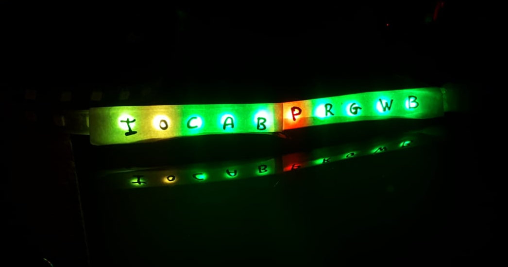
I m still new to Arduino, so any improvement is welcome. I failed to make a lib out of it for now
 ancient skiff
wahoo I completed my 3d printed keyboard and posted the design files to thingiverse. https://www.thingiverse.com/thing:4129809

I was inspired by the SiCK-68 but wanted a tenkeyless layout, so I designed it from scratch.
Here are some other features I added in my design:
Case holds plate at a slight incline
Threaded inserts are used for the case-closing screws
Provision for 4 8-neopixel strips inside,...
 onyx summit
Almost finished with my first major project, just some assembly and gluing left. Designed the 3d printing, PCBs, and code all by myself (and taught myself most of that for the project). Check out my Analog Binary Infinity Mirror Clock!

GitHub
Contribute to bamapookie/analog-binary-infinity-mirror-clock development by creating an account on GitHub.

Using an infinity mirror illusion as "hands," construct a binary clock that moves like a normal, analog clock.
 exotic pagoda
Scraped this motor off of a dryer. Im thinking about making it a duct to remove fumes around a 3d printer thats coming
And im also making an alarm clock
 rugged sail
3D printed sphere using alpha brass pla

This is another experiment with our Creality Ender 3 Pro. As you will see in the video, we are 3D printing a shiny smooth sphere, with the printer.
More Read Here: https://www.delhitechnologyclub.com/3d-print-sphere
👉🏻 F A C E B O O K
https://www.facebook.com/delhit...
 solemn bolt

Another day another Glockenbot video. I really enjoyed making the projection mapping for this one. It really gets good at the 2:00 mark.
This has been a fun project

 upbeat geyser
That's a whole lot of digits, is your sensor really that precise, or is that conversion artifacts?
 sharp comet
@upbeat geyser Its the on board sensor on the CPX. Im not sure how precise it is. But in a newer version i do have it rounding to 2 decimal places.
torn viper

Got Linux booting on the FPGA of DE10 Nano board (not the ARM SoC part) https://t.co/3GclaHEX1L
One PR in to litex-boards, I'll do up the PR to linux-on-litex-vexriscv shortly
#fpga #MiSTerFPGA @IntelFPGA @enjoy_digital
 Twitter
upbeat geyser
Twitter
upbeat geyser
A while back, my water heater started tripping its overtemperature cutout. I wasn't sure which thermostat was responsible, so I hooked up monitors for both heating elements, and a temperature sensor and had it log to an SD card for a while. It finally tripped again, showing that the lower element came on and stayed on until the water hit 75°C, at which point the overtemperature cutout tripped again.
 upbeat geyser
Yes, the overtemperature sensor was right to trigger.
 cedar dew
I’ve made progress with my circuitplayground python
solemn bolt
Looks great
 kind harbor
Spent my weekend doing a pointcloud scan of my face and rendering it in Blender. I have a few more ideas now 🤔
solar yew
Scored 0.025 aluminum from hardware store .. with a drywall nail.
Folded it back on itself on a good break line. Then dressed the fold with a file.
24 x 8 now 19.5 x 8 and mounted against the rear face of the front panel (inside the Hammond 20x11x4 sloped cabinet).
So now I have all kinds of cheap real estate to play with, inside the cabinet, without drilling the front panel.
I went with a front panel-exiting power supply cable (eventually with a good grommet for the hole).
When the back of the cabinet comes off (bottom, in normal orientation of this model) I don't want to be disconnecting any wires.
So everything is bolted in some manner to only the front panel half of this chassis.
coral gull
3:30AM project: new pickups for my SG copy guitar
coral gull
It's done. I'm impressed so far, these cheap eBay pickups seem to be less noisy than the originals. And sound good from what I can tell right now.
upbeat geyser
Nice! Looks great too.
sharp comet
Preparing for the game with  https://gfycat.com/livelypepperydunnart

 soft condor
Surprise box of ~800 single-inline resistor packs from Electronic Goldmine... having more fun with these than I should probably admit.
upbeat geyser
Looks like you got a better assortment than I did. I do like Electronic Goldmine, but my resistor assortment was a whole box of the same one.
Got these cool purple neon-like bulbs there a while back
 obtuse walrus
This may not look like much, but it represents a solid bodge and proof of concept: https://cdn.discordapp.com/attachments/480464358674006026/673713414174146600/PHOTO_20200202_211502.jpg
it'd look like more if it displayed!
That... is the top left 8x8 pixels of my Raspberry PI's HDMI output, replicated in Neopixels
The tools for this were all over the place, so this represents a Python script hooking into a compiled C library to get framebuffer metadata in a super lightweight way
That is the Raspbian mouse cursor, for the record
Upcoming, I implement a sampling algorithm and I can have an easy-peasy screen-extending Ambilight clone for any content displayed by the Pi
Which should then, in theory, include Steam In-Home Streaming, movie playback, on-Pi retro gaming, etc.
upbeat geyser
Impressive hack! I like it!
coral gull
There's one project I want to finish this month. I've converted a guitar (similar to the one I posted yesterday) into a bass, and all that's left is doing the paint job I want (translucent green with 4 white stripes in the front and back). I have another set of those pickups which I'll use on it, too.
feral magnet
I got my maze game working properly !
everything is there : https://github.com/Marius-450/Maze_CP
GitHub
A little maze ball game for Circuit Playground boards with TFT Gizmo, driven by the accelerometer. - Marius-450/Maze_CP
I'd love to have some feedback 🙂
ping @upbeat geyser who said it was a cool project a few days ago 😛
upbeat geyser
Perhaps I should obtain a Gizmo so I can try it out
feral magnet
I'm proud ... I made all the steps (see Etch-a-sketch and Chateau in my github account) as planed, and finally I have something better than just a PoC or an example.
 scenic siren
@feral magnet I emailed a link to your message here with your image and GitHub link to our group to get it added to the Python on Hardware newsletter.
feral magnet
TY 🙂
scenic siren
For future reference, it's hosted on GitHub, so you can submit links and photos yourself via PR if you have things you'd like included in the newsletter. https://github.com/adafruit/circuitpython-weekly-newsletter/tree/gh-pages/_drafts

GitHub
Community newsletter for python on microcontrollers - adafruit/circuitpython-weekly-newsletter
@feral magnet So next time you create something super nifty, feel free to submit a PR for it to the newsletter. 🙂
feral magnet
I'll do with great pleasure. thanks !
 spiral crest
my first breadboard experiment with NPN transistor 😄 i did not blow it up
 empty rose
I got addicted to mod stylish Swiss 60 - 70's radius with PI's and HifiBerry's (And some arduino's to make the original potentiometers work)
HifiBerry released a fancy OS with Bang & Olufson, its super easy set up and use. (I alway found the Volumio OS to be a bit of a UI mess)
 delicate basalt
@empty rose that looks like a lot of fun, what type of options does the B&O OS give you?
empty rose
@delicate basalt https://www.hifiberry.com/hifiberryos/ not to many options. Its just has a very clean UI, and everything works very well out of the box
HiFiBerryOS is is our version of a minimal Linux distribution optimised for audio playback. The goal isn't to add as much functionality as possible, but focus
delicate basalt
thanks! The #nowplaying endpoint looks pretty handy for making an external display of some sort 🤔
 plush gorge
Printings fun, but the real fun is when the printing is done & it's time to put 'em together. :-D Any guesses what it'll be?
 terse totem
@plush gorge is it a tripod mounted toothpaste tube squeezer with a sniper stock, trigger, and scope?
plush gorge
Lol, nope @terse totem . Think sinking heat.
terse totem
aha! a threaded insert mounting tool thing!
plush gorge
Yup, u got it! No reason not having the specified parts should stop ya from making what u need or want. ;-)
 west zinc
Hey folks, finally learned how to drive stepper motors to build a two link SCARA robot arm. Added a couple of display elements so it could drive a digital binary/analog clock.

https://youtu.be/KadsL82TdRcThis project is a vehicle for me to learn about steppers, SCARA arms with inverse kinematics, bimodal stability of switches, mechanical linkages and some PLA flex to create friction sliders. It uses a two link SCARA arm to control four binary indic...
Here are a couple important things I learned. First challenge was to figure out how to make the axles. I though that 3D printing axles would be tough since threaded holes probably wouldn’t work.
I found that you can buy a kit of those brass 5mm hex standoffs and make any length axle you want, in 5mm increments. Also they have M3 threaded holes in both ends.
I don’t have a lathe and can’t tap holes, so these 5mm hex standoffs with threads were a godsend. And since you can add or remove 5mm long sections you can adjust the length as you are iterating. Yay!
Next, I found bearings with fairly large openings but still relatively small diameter. I used these 12x8x3.5 mm bearings. (MR128). With a 8mm bore, this gave enough room for the 3D printed shaft around the 5mm hex axle.
So in a short summary: Hex standoffs are your friend!
signal loom
This is our robot. We are going to be going to Utica representing southern Westchester county in the NY finals! We compete in FIRST Tech Challenge if anyone is interested in following along.
 slate tusk
@signal loom nice to see another FIRSTer, Im an alumni of an FRC team
obtuse walrus
Congrats, fellow Westchester person!
sharp comet
@scenic siren Super cool spirit level example! I couldn't help but wonder if CPX + Gizmo could handle it... Alas not enough memory to run it as is. But I was able to get pretty nice results using OnDiskBitmap in the background and only a single Circle shape. https://gfycat.com/boilinggiantgoose
 scenic siren
@sharp comet Well done!
sharp comet
Finally had a chance to play with the new BLE stuff with CircuitPython. Made some valentines emoji sender/receiver for my wife: https://www.youtube.com/watch?v=aMJWyGEpyB4
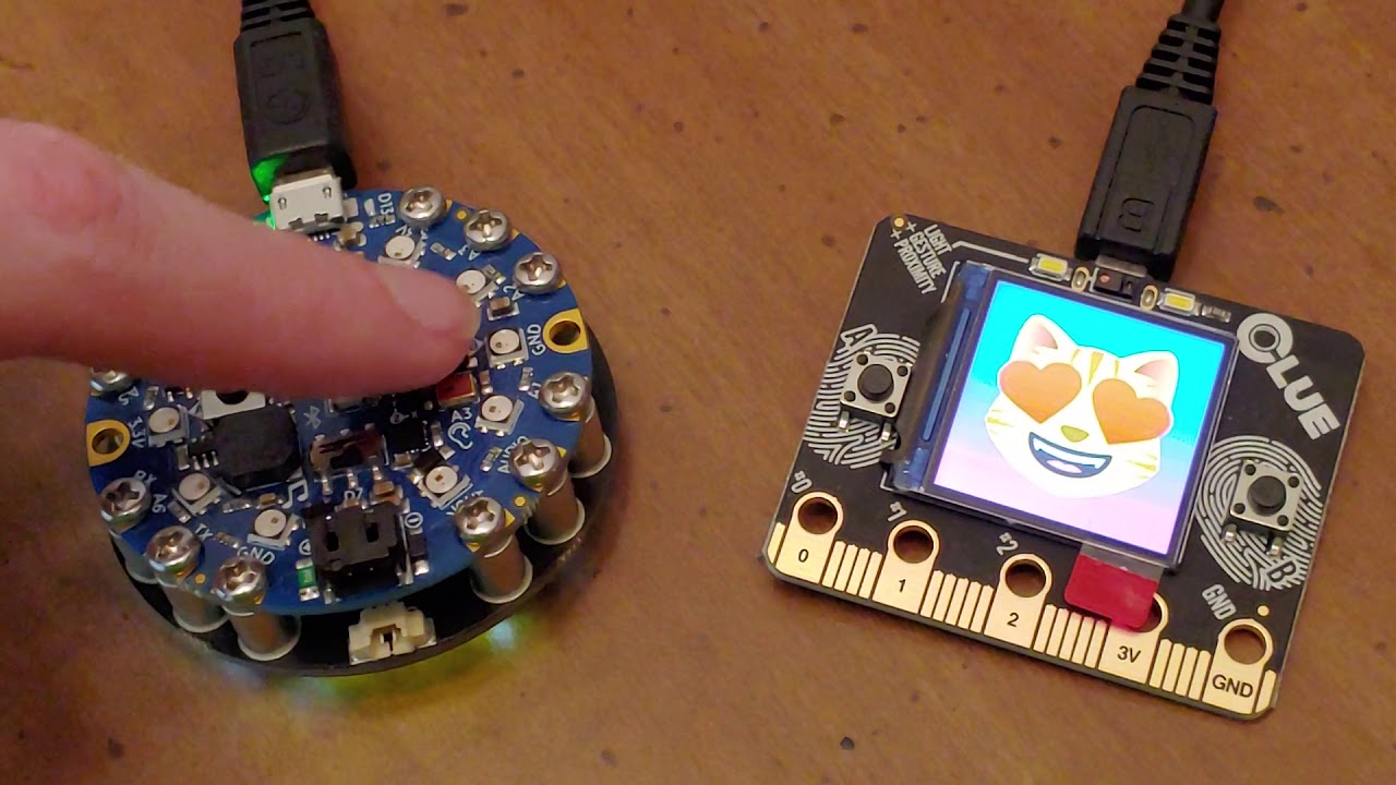
Made valentines emoji sender / receiver for my wife using Circuit Python!
obtuse walrus
Re: Screen mirroring on NeoPixels from a few days ago, I updated my hacky Python script to operate on a memory map object (mmap) of the framebuffer rather than using a normal file access and it's an order of magnitude faster, about 4-6 milliseconds per frame. That's plenty of time to do all sorts of fun pre-processing, and this is still in a single thread Python script!
It feels so good to get these kinds of speeds vs. the old Adalight-style hacks with Java screenshotting apps and whatnot https://learn.adafruit.com/adalight-diy-ambient-tv-lighting
 feral magnet
there is always more than one way to do it. great job !
ancient skiff
3d printed pcb vise (thingiverse design)
empty rose
Building a small 24/7 DragonBall TV for 7 year old nephew!
Used an old dia viewer i found and my parents place
empty rose
its a pi 0 with the a small tft and amp ordered from adafruit
ancient skiff
Wow that looks amazing
sharp comet
CLUE is so much fun to play with  🔍 I made a script to use it kind of like Dumbledore's Deluminator, absorbing and then emitting light. https://github.com/FoamyGuy/CircuitPython_CLUE_Deluminator

GitHub
Contribute to FoamyGuy/CircuitPython_CLUE_Deluminator development by creating an account on GitHub.
 glad sable
Made a short and sweet magnetic sensor graphing script for the Adafruit Clue! The code could probably be a bit cleaner and more efficient, but this is what i came up with quick. Check out the source code here: https://github.com/AndrewTribble/adafruit_clue_Magnetic_Graph/tree/master

GitHub
Contribute to AndrewTribble/adafruit_clue_Magnetic_Graph development by creating an account on GitHub.
cedar dew
Hi guys. I’ve loaded this python head stl and fusion360 files you thingiverse if anyone is interested

This is a python head that I modelled to hold my Circuitplayground. I use the head to mount to code on the go while I'm riding the bus to work.
I've included the video I made of how I pieced this all together.
I added 2 extra strips - 1 for the eyes for the tilt sensor and ano...
 spring elm
@cedar dew that's really cool
cedar dew
Ty i will still add better segments for the back
plush gorge
Taking apart 1 of the pumps that I have...
Any idea what'll happen if I apply a DC voltage to the red & black wires?
Now the $64,000 question. How do I get the big heavy metal part off of it?
Give me a lever long enough and a fulcrum on which to place it, and I shall move the world.
Good ol' Archimedes 🙂
Okay?!? What kind of motor is this set up??
Any thoughts?
@marsh quest are you possibly still on?
This is the inside of the pump. I have a pair of these pumps & was thinking that these motors might be good to make home power generating wind mills.
upbeat geyser
@plush gorge Looks like a vibratory or induction motor. I think the red and black wires go to a capacitor. Hooking DC to them will probably not do anything useful.
plush gorge
Good morning. Thought I'd add that I was able to deduce that the permanent magnates are in that metal center piece that's sticking up, while the coil windings are in the large piece. Something that I wasn't expecting is that this is isn't just a water pump, but the water is channeled to flow between the permanent magnets and the coil windings, keeping the motor cool. 🙂 The only thing I wonder now, is could this motor design have enough kick to generate electricity adequately. & how am I going to cut through the 5/8th inch thick steal piping to access the motor's output shaft.
upbeat geyser
Many pump motors are liquid cooled. While I usually flame cut thick steel, it's probably not a good idea in this case. Perhaps an angle grinder would be appropriate.
You might also be able to get away with just cutting a small opening concentric with the shaft, using that to bring another shaft in, and join them with a shaft coupler.
Alternatively, you might be able to replace the entire pipe end with a simple flat end plate, but you'd have to replace or relocate the bearing.
plush gorge
Morning @upbeat geyser
That makes sense @upbeat geyser . Even using an angle grinder, I've never cut through metal this thick. It'll be interesting to say the least. Is there anything I should know or do when I prep or actually cut into it?
Also, how do you think this type motor will do as a generator once I get it hooked up to a drive source like fan blades to make a wind turbine?
upbeat geyser
I don't have a feel for how it will do as a generator, I'd give it a spin and see.
 bitter hazel
This is our robot. We are going to be going to Utica representing southern Westchester county in the NY finals! We compete in FIRST Tech Challenge if anyone is interested in following along.
@signal loom cool bot. I was lucky enough to meet up with a north carolina team last week when I was there and help them troubleshoot their bot. they placed second in the competition last sat and would be advancing to the next level. I have been thinking about starting a team in New York city but cost, space and effort are the biggest hurdles. I was amazed to have met 5 teenage boys that was able to meet on a regular basis and sit still long enough to build a robot and write code for it. I hope you do well in the finals!
 toxic yew
I finally got around to assembling a USB breakout in the originally intended configuration.
The first version I assembled used terminal blocks in place of the downward facing headers.
signal loom
@bitter hazel thanks for the kind words and your effort as a volunteer. I have attached some new video of our current bot as well as our display wall.
bitter hazel
@signal loom Do you know of any FIRST teams that are based in new york city?
bitter hazel
FTC
signal loom
I’ll make some calls and get back to you. You are interested in mentoring?
@bitter hazel
 half reef
it appears my clock chip is not in perfect working order 
upbeat geyser
Got some missing segments myself
plush gorge
Lol, 4.2 volt A.C. with only a sixth of a turn with an allen wrench. So loving my PMAC motors! :-) Can't wait to get these hooked up to a wind mill!
@upbeat geyser
empty rose
Done:

Do need to figure out why the sound quality is so bad all of a sudden, was quite ok in the previous vidro
Any clues?
 lucid bloom
Working on a project with some friends, it's an arcade racing game with fans tied to player speed. A water mister for hitting water barrels. A hacked PS2 racing wheel, the wheels buttons and potentiometer go to an Arduino that plugs in/shows up as a joystick with the pi 4. The rumble packs and water mister go to an Adafruit motor HAT and the fans go to a Cytron Dual Motor Driver HAT. There is much work to be done making the arcade cabinet but the underlying functionality is all there. I will periodically post updates as we progress.
lucid bloom
These are from when I was testing the rumble pack/fan code
 patent nimbus
evening all hopefully im not breaking any rules but iv made a video on how to build a simple logic probe hopefully it might prove use full to some people 🙂 https://youtu.be/WCgTf-XEmUY

in this video we will be looking at how to make a simple Logic probe.
you don't have to be an expert to make a logic probe in this video we will look at what logic probe is and how to use one. ending with how to make a simple logic probe for your self.
spiral crest
who can resist old school LEDs lol
Reading 1: 3.3V rail
Reading 2: 3.3V rail through 1M:10K divider (calculated)
Reading 3: Potentiometer swiper
Reading 4: GND
Timer 1: duration to get A2D voltages
Timer 2: duration to display voltages
LEDs <-> same as Reading 3.
toxic yew
I finally got around to converting my chrome book to a GalliumOS (Linux) book.
 crimson egret
@rustic stag I won't be able to show up for a while, I'm teaching a Python/CircuitPython at the time of the live show.
I was wondering if I can sneak in a question for ask and eng. I've made a 30% translation of the welcome to CP here https://github.com/fede2cr/adafruit_learning_spanish

GitHub
Translation of the learning guides from Adafruit to Spanish - fede2cr/adafruit_learning_spanish
I hope to finish it this weekend. So, my question is, is there a visit count for the learning guides, or something similar that I can use to prioritize which guide to translate next.
(I wanted to show the timeline of micropython today, as well as the Maix RISCV running Linux 😦 )
scenic siren
@crimson egret This is great! I know there are stats available internally, but I don't see them available externally. I will look into it for you though. It may be that we can provide you with suggestions for other guides to translate, but I don't want to make any guarantees.
crimson egret
Absolutely, that would be more than fine. I would only need a top three or five, so I can get to them one by one.
scenic siren
I'll ask about it in our internal meeting this evening. Do you mind if I direct message you?
crimson egret
Not at all.
west zinc
Just finished a TINY bedside clock. Uses a 1.3” TFT display, an ItsyBitsy M4 express and the precision RTC breakout. Clock design is my wife’s “morphing” design where it shows part of the hour number depending upon how much of the hour is “used up”. It’s about 8:45pm!
Thanks for the Adafruit crew for making it easy to piece together a project with electro-bits and make something useful.
sharp comet
@west zinc very cool I like the way it displays
Do you have it written up or the code online anywhere? I'd love to learn a bit more about how you made it.
sharp comet
Excuse the potato quality camera work, but here's a neat Android / Circuit Python project I'm working on for the day job. Android device driving video content on a screen and communicating via USB Serial with an Itsy Bitsy M4 in order to receive triggers from the product pedestals as well as use PWM to control the lights embedded within. Shown here with set up for 4 products but thanks to all the IO pins jammed onto the Itsy Bitsy our custom board has support for up to 10 triggers and 10 LED strands. https://www.dropbox.com/s/rtqaj28h082u8n5/20200220_104244.mp4?dl=0
 delicate basalt
Trying again now that I’ve fixed the month.
Google calendar fed day view. Still have some design features I want to add, but works as a proof of concept
 fierce stream

Created a Haunted house music player for my son, https://github.com/h3lls/EliPlayer

Turns out if you want to use the DFRobotDFPlayerMini for playing mp3's it takes up almost every byte of memory even throwing everything in progmem. That didn't leave enough room for the 1.14" TFT display since the SDCard and the GFX libs alone take almost 70% of the available program space.
So I just split it to two different arduinos. At some point I am going to move it all to a teensy which will have no issues and also give some extra pins for doing LED light shows.
 stark lava
UniPi - WiFi voucher vending machine project: https://github.com/kbeflo/unipi

GitHub
WiFi voucher vending machine leveraging UniFi controller and UniFi access points - kbeflo/unipi
@upbeat geyser
upbeat geyser
Nice build!
signal loom
This is my first major personal "robotics" project. My friends challenged me to go start a battlebots team, so I did. I taught myself Fusion a few weeks ago and started designign my Beatleweight, Afterburner
 hidden stratus
Not sure where to post this (I miss the old G+ community a bit) but in case someone wants some Feather LORA instructions and code example I put together a framework that worked good for me. Thanks @marsh quest for such a great set of boards! https://youtu.be/zXHMCecD_5k

Code & Instruction for the Adafruit Feather + LORA radio to add wireless communication to any project.
PCBWay: http://pcbway.com
Subscribe to my other channel! https://www.youtube.com/channel/UCTUoaahtQ3eIBtUvwaE2ixw
Join the Patreon Squad! http://mkme.org/Patreon
Full code...
spiral crest
@signal loom see if you can find repeats of Robot Wars on the BBC. The ones that did the best had a skirt 0.5mm all the way around and could drive either way up.
signal loom
Yeah. I use a lifter as my primary weapon so if I end up on my head, I can use that to get back over. I also have been reading the Riobotz combat robotics tutorial and that has a lot of useful resources and explains a lot of the math that goes into designing a bot like this. @spiral crest
I will post here again when I start my building
solar yew
i got to admit.
this is awesome.
https://blog.adafruit.com/2020/02/21/dropping-a-massive-fleet-of-paper-airplanes-from-a-giant-r-c-controlled-paper-airplane-flitetest/

Adafruit Industries - Makers, hackers, artists, designers and engineers!
In this Flite Test video, the team decides to use their giant R/C plane that’s in the form of a classic paper plane as a mothership from which to launch hundreds of actual paper planes. A sil…
now add this to each paper plane.
https://www.youtube.com/watch?v=GSDNgnhJ-FM
if possible some light sensors.

At the request of many viewers, I decided to take on the challenge of making an RC paper airplane! Turns out its not too hard at all to accomplish!
3D printed part
https://www.thingiverse.com/thing:2905006
song:
https://www.youtube.com/watch?v=18JQUYgpOlw
MY WEBSITE::::...
add AI
west zinc
Hey @sharp comet, I haven’t written it up yet. Stay tuned and I will put it up somewhere. It’s a tiny version of this LED clock designed by my wife. It uses a 3D printed grid and a paper diffuser in a photo frame.
sharp comet
Super cool 😀
west zinc
No electronics today. Made a baby Stitch instead.
 rocky beacon
Arduino music player I have been working on:
https://www.youtube.com/watch?v=kasEZQ5rv2g
GitHub repo: https://github.com/JarkkoPFC/arduino-music-player

TFT visualizer for Arduino Music Player, running on Teensy 3.6.
Music: "Rollin'DowntheStreet" by FearofDark (https://modarchive.org/module.php?169549)
Project GitHub page: https://github.com/JarkkoPFC/arduino-music-player
TFT Display: https://www.pjrc.com/store/display_ili934...

GitHub
MOD/S3M/XM/IT Music Player for Arduino. Contribute to JarkkoPFC/arduino-music-player development by creating an account on GitHub.
 mellow wedge
The two rivals
solar yew
coopetition
 hidden saffron
Current set up, using a laser to find the edges of a part and check for squaresness of the part. Planning on switching to lidar based sensors vs laser just for sake of speed.
After finding the edges another mill screws on the drywall and locates the parts using data from the scan
rocky beacon
Here's another project I have been working on, Arduino 3D graphics lib, currently running on Teensy & ILI9341
https://www.youtube.com/watch?v=Xs_5Sv9oBtk

Got the 3D rendering working with Teensy 4.0 and DMA, which is able to render the model significantly faster than T3.6. This also features cluster visibility culling, which does conservative culling of unseen section of the model (back-facing & occluded) without need to transf...
rocky beacon
This is doing software rasterization because there's no GPU on Teensy
west zinc
Stitch has evolved
solar yew
west zinc
@solar yew too cute!
 bold tiger
project in process but Im making my own pick and place machine
solar yew
So when i was a teen i got a tiny toy tank IR controlled.
Since then the lithium cell faded 72th scale in size i knew i would search hard to source a battery.
So am i slowly been doing a write up of them.
- disassembly.
- replacing the logic from a cheap ir to a k210 and esp32.
- building the logic
- building a charging dock.
- coding navigation.
- coding different AI models and methods for more realistic combat detection.
- release my final project and code like i used to in the past without crying about failure.
i have a collection of e'm
sharp comet
Neat! Id love to see the writeup @ @solar yew
sharp comet
@solar yew Neat! Id love to see the writeup. (Sorry for wrong ping GoblinSlay3r, phone discord client was getting confused or something I think.)
west zinc
@sharp comet Here is the write up on the 1.3” TFT mini clock:
https://hackaday.io/project/170191-13-tft-clock-with-morphing-display

This project is a tiny bedside clock built using a 1.3" TFT display paired with an Adafruit Itsy Bitsy M4 and the Adafruit high resolution clock time (DS3231).
My wife provided the design direction of the hour display and the minute hand. She chose a "morphing" design where...
Not sure why the first image isn’t showing up since it shows fine on the gallery.
sharp comet
Awesome 😀
west zinc
Thanks @sharp comet the image is working now. https://hackaday.io/project/170191-13-tft-clock-with-morphing-display

This project is a tiny bedside clock built using a 1.3" TFT display paired with an Adafruit Itsy Bitsy M4 and the Adafruit high resolution clock time (DS3231).
My wife provided the design direction of the hour display and the minute hand. She chose a "morphing" design where...
sharp comet
Hooray! love it.
I really like the nice enclosure with room for the itsy bitsy in the bottom. Makes me want to grab one of those screens!
 deft bloom
Just been working on a modular control panel with rotary encoders, LED displays and Cherry MX buttons
(whoops, didn't mean to add a self reaction lol)
solar yew
Nice!
solar yew
@west zinc i have a few of those displays floating around on a few pi's
i think the pi could benefit from a screensaver this majestic
 half sage
Hey everyone. I have been working hard and managed to get the Robo HAT MM1 ported over the MakeCode so that it is officially supported. This gives you so much more you can do with it. The tutorial / story on how it was done and the difficulties will be completed later.
MakeCode Maker - Blocks / Javascript editor
A Blocks / JavaScript code editor for MakeCode Maker Boards
solar yew

GitHub
The best way to write secure and reliable applications. Write nothing; deploy nowhere. - kelseyhightower/nocode
😂
 craggy parrot
and use "Write Only Memory" devices.
west zinc
If you have an LED ring clock, here are some holiday chime ideas:
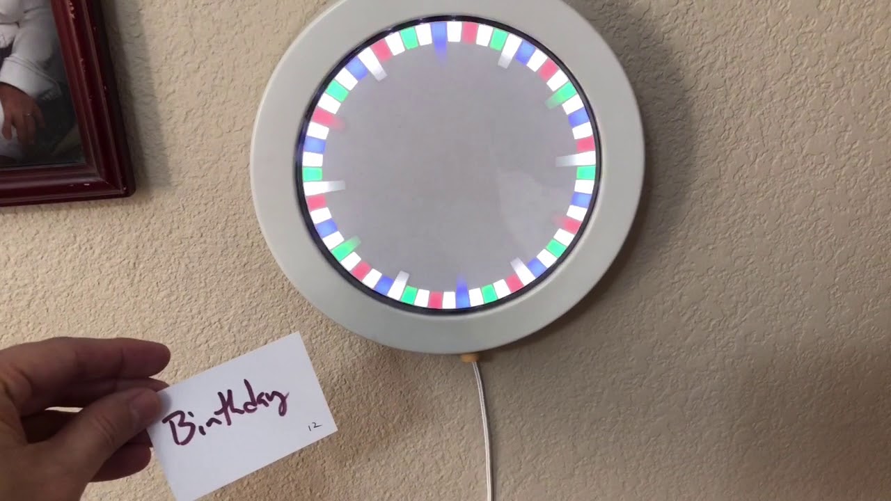 glad sable
One neopixel driver at 250x magnification
upbeat geyser
The result
 bright solstice
just got an arduino today, i didnt make much of a program here but you gotta start somewhere right? https://gfycat.com/littleoddasianelephant
 upbeat geyser
Pretty!
bright solstice
haha thanks, i got sucked into a rabbit hole of videos on breadboards and now i cant stop buying things :/
I have to wait a week for a few EEPROM chips to come in, i want to use those and some seven segment displays to make a d20 randomizer
upbeat geyser
I know that feel
 dusk zinc
Is that your 1MHz computer?
bright solstice
im also really tempted to spend 30 bucks for a one pound grabbag of IC's i saw on ebay lol
upbeat geyser
It's about 10Hz right now... This is my 1MHz computer.
bright solstice
oh dayum
dusk zinc
Are the other boards all RAM?
upbeat geyser
Yup. Eventually I realized I wanted more RAM, but Motorola bus RAM boards were expensive, so there's a Motorola-to-S100 converter hiding in the box, and they're ordinary S100 RAM boards.
bright solstice
that first pic you sent with the Mega, what does that circuit you made do?
is that an eeprom programmer maybe?
upbeat geyser
I'm breadboarding an 1802 CPU, a little bit at a time. Right now, it's just the CPU and address demultiplexer. I'm planning on using a FRAM chip for both RAM and ROM so it can run programs.
bright solstice
ah, i understood most of those words XD
upbeat geyser
The Mega is the clock generator and bus analyzer, Ben Eater style.
bright solstice
ah, yeah ben eater is the rabbit hole i got into lol
upbeat geyser
I'm aiming to do the same sort of thing Ben Eater is doing with a 6502 breadboard, but I'm using the Mega as the clock source instead of Ben's 555 circuit, and using a FRAM chip as both the RAM and ROM so I don't have to mess with programming an EPROM and wiring up two chips.
And, of course, using an 1802 chip instead of a 6502.
dusk zinc
Cool... retro but with some modern conveniences 🙂
upbeat geyser
Yeah, that's how I feel about it.
Planning on using a cheap LED display to start with, Lee Hart style.
bright solstice
ahh, what i want to do is make a manual eeprom programmer and use 2-3 eeprom chips to make a circuit that cycles through the numbers 1-20 very fast as long as you hold a button, then output the result to two seven segment displays.
then take that to a D&D session in a couple weeks lol
its simpleish(i think) but again gotta start somewhere right?
upbeat geyser
Ah, like an EEPROM driven sequencer as a die simulator. I like it!
bright solstice
yeah, like the first chip would just tie a few bits of its output to its adress register and it would just loop over and over... i think
upbeat geyser
I'm unsure if you'd need a latch to keep things updating in synch, but the best way to find out is to try it!
bright solstice
also not sure if im gonna have enough output pins on the first chip... i looked online trying to find a eeprom chip with 16 outputs instead of 8 but i couldnt find such a thing
upbeat geyser
Hmm, there are 16-bit ones, but they don't have parallel interfaces, which is what I'm guessing you'd want.
bright solstice
oh wait im dumb i can just use the output address to also be the output die roll number at the same time
yeah i saw those ones, and i didnt feel confident enough to want to deal with those just yet
upbeat geyser
True!
You could use a second PROM to decode the count/address to 7-segment patterns.
bright solstice
yeah thats what im thinking, probly gonna need 2, one for each 7-segment
i found a lot of 7 eeprom chips on ebay for 12 bucks thats local-ish so i grabbed it
upbeat geyser
Or you could have an oscillator drive both another address pin and a digit select lead, depending on how you like to do things.
bright solstice
yeah i saw ben eater do that with the single eeprom to control 4 leds but im not sure im gonna do that
upbeat geyser
Right, it's your design, you get to decide how you want to do it.
bright solstice
plus i also want this thing to be really fast, hopefully changing the number hundreds of times a second, so it would be impossible to time your button presses
upbeat geyser
That should be totally doable.
It occurs to me that even if there's a synchronization issue and it makes a weird jump to the "wrong" number, so what, it's supposed to be random anyway.
bright solstice
yeah like as long as i can get it all to fit on one board nicely (using a seperate board to program the eeproms) ill be good
though.... if i could also tie a 20 roll to cause extra leds to light up...
#featurecreep
upbeat geyser
The only two pitfalls I see are the possibility it jumps to a number like 30, and you'd have to decide what to do if it picked that, and the possibility that it gets into a weird metastable loop so it just ping-pongs between two numbers and skips all the others. However, there are ways to deal with all that if it happens.
bright solstice
well my idea is that say address 12 outputs a 15, then you tie that to its input address lines so the eeprom then outputs whats on address 15, which could be a 7 for instance, then it reads address 7...
eventually looping back to address 12
upbeat geyser
Right, I get that. But without a synchronization register, there's the possibility that one of the data bits is a little faster than the others, so it jumps to an address that's a mix of the old and new address bits.
bright solstice
oh but im using the big eeprom chips that have pins for all the addresses and outputs though, i just need to make the clock pretty fast too, ugh i forgot the clock lol
still pretty much a noob on this lol
upbeat geyser
That's just it: PROMs aren't normally clocked, you just give them an address and (as long as the enable and chip selects are set) they just spit out data. A synchronization register would accept a clock, grab the data, then on the next phase output it (which would go back to the address input). That would avoid those timing issues by only sampling the data when it was stable.
It's just a chip with 8 data inputs, 8 data outputs, and a clock input that contains flip-flops that "latch" the data.
bright solstice
coudnt i hook the clock to the enable though?
upbeat geyser
74373 and its cognates is a popular choice (that's the chip in the upper left on my 1802 breadboard: since the 1802 outputs its 16-bit addresses 8 at a time, I need the latch chip to hold the high order bits until the low order bits are ready)
bright solstice
since im not planning on it not cycling through the numbers, just and gate the button and clock to the enable?
upbeat geyser
You could, but you'd still have what's known as a "race condition": as soon as the chip is enabled, it'll start trying to output the data bits, but they probably won't all show up at exactly the same time.
bright solstice
hmm
upbeat geyser
It's a subtle issue, but could result in the chip just jumping back and forth between (say) 3 and 16 and skipping all the other numbers.
For some D&D campaigns, that wouldn't be a problem, but for others it could range between hilarity and disaster.
bright solstice
could also theoretically fill the entire eeprom memory with the numbers 1-20 so that if it does accidently jump to say address 37 it would be able to jump back into the normal cycle...
upbeat geyser
The proof is in the pudding: try it and see.
You could just decide to re-roll if it happens to stop on 37 (but I'm guessing for 1-20, you'd just have 5 address leads, so the only possible numbers would be 0-31)
bright solstice
yeah, its gonna be a tight fit to get everything on the board as it is, i wish i had a couple tiny AND gates i could use, the ones i have are quad and gates
upbeat geyser
There are single-gate chips available, but they tend to be surface mount (I have been known to mount them on 6-pin DIP adapters, I probably have a picture somewhere). However, you might also be able to get away with "wire-or" or diode logic.
bright solstice
yeah it will be interesting to see what i can do when i get the parts in in 6 days or so
upbeat geyser
On the off chance that you do decide you want to breadboard an 1802, the folks at BG Micro have this set of parts available: https://www.bgmicro.com/9Z1510.aspx
bright solstice
haha maybe some day XD
upbeat geyser
I went ahead and took a picture of a little robot I built using a couple of the single-gate chips mounted on DIP adapters (the small red ones) plugged into little breadboards
bright solstice
lol i just did the math, 3 eeproms, one quad-AND, and a 555 timer, with 1-pin gaps between each chip uses exactly 64 pins... my breadboard has 63 XD
though i can squeeze the 555 timer and the quad and together just barely
though that also means i have no room for the button... or the 7-segs 😦
upbeat geyser
You can probably see I don't have 1-pin gaps between my boards.
bright solstice
gosh someday im gonna have to try messing with robotics. i actually have an old lego NXT kit in a box
upbeat geyser
Heh, I'm playing with my old NXT kit, trying to build an automatic Lego sorter. I'm using a tractor tread as a conveyor belt.
bright solstice
but when i wanted to mess with it years ago i couldnt get access to the programming software. the software only worked for XP at the time and i had win7, lego wanted to charge like 100 bucks to get the win7 version of its software back then 😦
but i found out a few days ago that the software is free again for it
upbeat geyser
Yeah, I found that too, even cool stuff like a Python interface
I picked up one of the Lego motor/sensor Arduino shields too.
bright solstice
though i always had issues building with the NXT compared to the original robotics kit, its hard to wrap my head around making things that actually align with those darn motors and such
upbeat geyser
I'm getting used to the different Technics mindset too.
bright solstice
it just felt like every pin was in the worst place possible
upbeat geyser
I keep running into "off by half a stud" issues.
And there are half-stud adaptor bricks available but do I have to use them all the time?
These guys
bright solstice
oh, thats what those were for?
upbeat geyser
I'm not sure what they're "for", but I keep needing them!
bright solstice
hmm, i wonder if i could manage with just 2 eeprom chips... 5 output lines on the first chip for the address, and then 3 + 8 on the second would be 11 remaining pins... bleh that isnt gonna power 2 7SD's
actually... the first 7SD only needs to display a 0, 1, or 2...
upbeat geyser
That saves a few pins. Or you could just use 7447 or other decoders instead of whole PROMs.
Hmm, 1 PROM, a 74185 binary-to-BCD decoder (16 pins), 2 7447 BCD-to-7-segment decoders (16 pins each), might fit
Or use 2 PROMs, and use the digit multiplexing trick to make the second PROM drive both digits.
bright solstice
i mean that solution uses 3 sets of 16 pins, same as 3 eeproms
ugh i can actually remove one pin for the first seven segment display, but still leaves me 2 pins short for using just 2 eeproms
mainly either that segment B is always on or segment F is always off
wait no i can just tie segments AGED to the same pin, and have zero be no lights on
which i think gives me exactly enough output pins
actually gives me one pin spare, 3 pins for display one and 7 for display two
upbeat geyser
Did a quick doodle of how I was envisioning using a PROM to drive 2 digits
bright solstice
https://i.imgur.com/XrOLhCg.png heres how i see it working
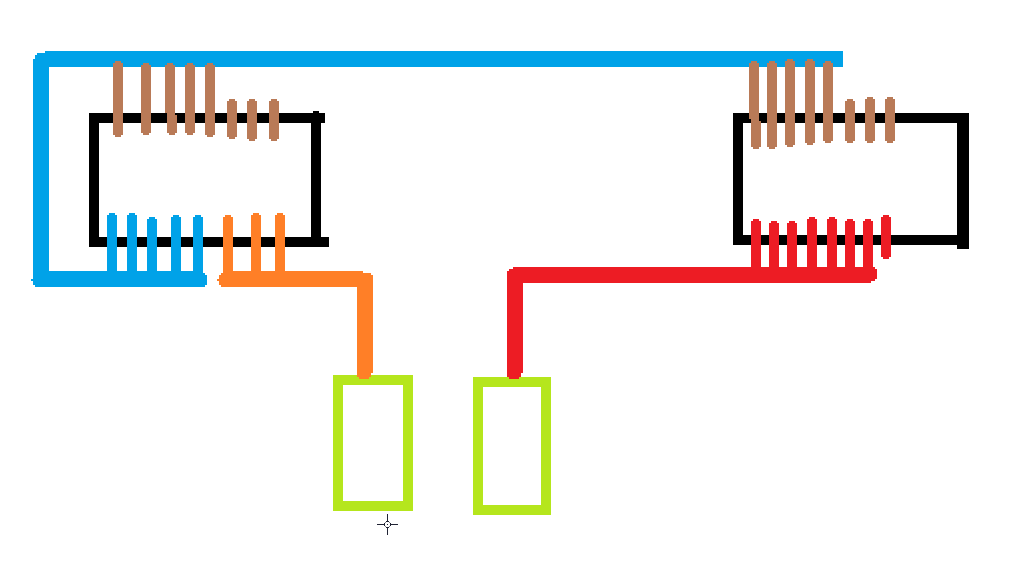
the brown is address in, the blue is the output address, orange hooks to the first 7SD, red hooks to the second 7SD
actually nice thing is i can use the spare output pin on the second eeprom to turn on some extra leds on a 20 roll
upbeat geyser
That works too, just spitballing here.
bright solstice
yeah i mean im kinda just planning this as i go now
i might have to try to make the one AND gate i need with pure transistors to save space
bright solstice
no wait i could just tie the output of the clock to one of the ends of the button, skipping the AND gate entirely
 civic vale
@bright solstice Be extra careful, running logic signals through a switch can have extraordinarily hard to track glitches.
Especially with a clock. Contact bounce in the switch will give you lots of extra clock transitions each time the contact transitions.
bright solstice
yeah i can def see that being a problem in most cases
luckily for this weird thing im building, hopefully it wont matter how often the clock does extra pulses, as long as its not faster than the EEPROM can handle
though i have 2 choices of chip to use when they come in, im getting some SST29EE010-120's, and two AT29C020-10PC's the latter seeming to be flash memory that acts like EEPROM
bright solstice
new idea: using the last 3 address lanes to add support for d6, d8, and d12's
could combine them and get d4's and d10's as well
bright solstice
also juust realized these eeprom chips are gonna be harder to program compared to the one i saw ben eater use, these chips seem to need several bytes of data programmed onto it all at once haha
bah now im grabbing some AT28C256's instead, will save me on pins anyway
deft bloom
First time using SMD components (especially this small). The 2.4mm x 2.7mm NeoPixel Nano’s
upbeat geyser
Difficulty of programming PROM/EPROM/EEPROM/flash is why I ended up preferring FRAM. Digikey still has many thousands of FM1808 in a DIP-28 package in stock too.
bright solstice
@upbeat geyser i looked at the spec sheet of the fm1808 and saw this https://i.imgur.com/5YO6rbl.png does the CE pin of most eeproms work the same way? cause i really need the feature of 'still output but stop taking in address inputs' on the eeprom im going to be using (specifically the AT28C256)

the doccumentation on the AT28C256 isnt as clear for a noob like me
if that isnt a feature of the AT28C256 then im going to need some weird latching 8-bit buffer thingy of some sort
oops ignore last thing
upbeat geyser
Hmm, I don't know. It would be cool if the chips would do it for you, so you don't need additional external chip to latch the address (or data).
That is why I mentioned the 74373 earlier: that's just what it's for.
bright solstice
ahhh, i see now
yeah i reaaaly hope i dont need that, it wont fit on the single board
upbeat geyser
Right, chip count is limited by board real estate.
bright solstice
i mean i have 6 small boards that just came in, but i really want to have it fit on one board
well i can probly re-watch bens video on the eeprom chip and see if he mentions my issue
but at the very least ill find out on sunday when the chips come in
well i ordered 5 of the 74373 chips for less than 4 bucks and its actually not gonna take 5 months to ship atleast
hey do you know what wire guage ben eater uses on his boards? is the same thickness as the jumper wires i have, but i have no idea how to measure mine lol. i saw some reels of jumper wires on amazon but it looked a bit thicker and i dont really want that
upbeat geyser
The link is on his web page: 22AWG https://www.jameco.com/z/JMS9313-01G-22-AWG-6-Color-Solid-Tinned-Copper-Hook-Up-Wire-Assortment-25-Feet_2153705.html?avad=234285_d19963989&source=Avantlink
Buy 22 AWG 6-Color Solid Tinned-Copper Hook-Up Wire 25 Foot
I imagine he uses plenty of the already cut and formed wires like this too https://www.jameco.com/z/WJW-60B-R-Wire-Jumper-Kit-350pc-22-AWG-14-Lengths-10-Colors_19290.html
Buy Wire Jumper Kit 350pc 22 AWG 14 Lengths 10 Colors
Here's Ben's parts page: https://eater.net/8bit/parts
bright solstice
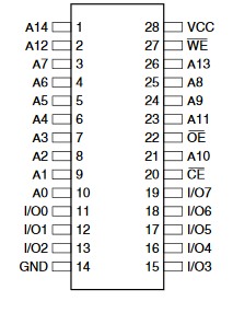
there shouldnt be anything wrong with treating address pins 12 and 14 as pins 8 and 9 right? https://i.imgur.com/LQ7Jc7W.png
 upbeat geyser
You'd have to shuffle the bytes you program it with to match, but yes, that's a common trick.
More specifically, you can treat A12 and A14 as A8 and A9, pin 14 is ground, and pin 12 is a data pin. 🙂
bright solstice
though now that i think about it, linking a13 a8 a9 and a11 instead may work out better, as i need 5 address lines for the main loop, and the other 4 lines for when i want to switch between d6/d8/d10/d12 modes
upbeat geyser
The address lines are basically arbitrary, as long as you arrange for the data to be loaded to match, it'll work fine.
bright solstice
i cant find a good deal on fram chips that have any good shipping times, so im mostly just gonna pray that the CE pin works the same way on this eeprom
upbeat geyser
I built one system that booted in 8-bit mode then upshifted to 16-bit mode. Technically, I should have moved all the address pins over by 1 bit, but I didn't have enough room for all that logic, so I just moved the high-order address pin to the bottom, interleaving all the bytes in one mode. I wrote a short program to shuffle the data to match before loading it onto the chip, it worked fine.
DigiKey ships pretty fast if you're in North America, don't know as much about other parts of the world.
bright solstice
nope i finally figured out that i cant have the eeprom output without reading an address, dang lol
upbeat geyser
I ended up buying more-available surface-mount FRAM chips and soldering them to DIP adapters.
bright solstice
and fram is just ugh spendy 😦
upbeat geyser
I'm not sure what you mean by "reading" an address. Do you mean latching an address by toggling /CE?
bright solstice
hey is there any surface-mount 24 pin fram chips? i only saw fram chips in 28-pin dips
yeah pretty much, just output what the last address had
but turning off CE on the eeprom chips makes the output high-z
upbeat geyser
Yeah, the parallel FRAM chips are all 28 pins and up.
bright solstice
if i get 2 24-pin eeprom chips i can fit in the 74373
upbeat geyser
It would be cool if there were a 6-bit latch in a 16-pin package, but I don't know of one.
bright solstice
yeah even with the 74373 now i have to hold 9 bits with that lol, so ill have to do some more trickery
upbeat geyser
I don't think you'd have to hold more than 5 bits (the mode select bits don't need a latch).
Hm, looks like you might be able to use a 74118 or 74119 hex latch, but those are obscure, obsolete chips.
bright solstice
oh yeah you right on the 5 bits thing
this seems too good to be true, 5 fm1808's for 7 bucks? https://www.aliexpress.com/item/33022842131.html?spm=a2g0o.cart.0.0.63493c00aigVp5&mp=1
upbeat geyser
Hmm, 74174 looks even better, hex D flip-flop in a 16-pin package.
I assume the cheap FM1808s are counterfeit, factory rejects, or pulls, but they might work for the sort of undemanding uses you and I are likely to put them to.
Hmm, "express shipping" is 6 weeks or so.
bright solstice
yeah its a long time but it is the cheap lol
upbeat geyser
I did order some of the FM1808B-PG from Rochester Electronics/DigiKey. They should show up faster.
bright solstice
i ended up getting 2 of the 24-pin eeprom chips for 2 dollars but its gonna be an eternity to deliver. there isnt really a local option for the at28c16 😦
upbeat geyser
Hmm, DigiKey has 74HC174 in DIP packages in stock for 50 cents apiece.
upbeat geyser
DigiKey has some odd FM28V020 chips (with no warranty, huh) for $4.24 apiece, but they're in unwieldy 28-TSSOP packages and what's up with the no warranty?
bright solstice
just did the math and the 74hc174 will barely fit into the board if i dont do the 'flashing lights on a 20' feature with the bigger eeproms im getting
will literally use every pin except 2 that the power supply would barely hang onto lol
bright solstice
so how do i use the 74174 exactly? how do i make it output but not input?
just by stopping the clock input?
upbeat geyser
Yeah, it just copies the input bits to the output when the clock pin goes high.
bright solstice
ahh ok
oh sweet they do take paypal, im gonna grab 10 of the things lmao
i mean its only 50 cents a piece lol
it says if its less than 14 ounces of weight i can get pretty cheap shipping, any idea how much one of these things would weigh?
upbeat geyser
A few grams, even a handful of them and packaging should be under 14 ounces. I usually use the cheap USPS shipping, but you can even get free shipping if you're in no hurry.
bright solstice
dang its probly not gonna ship til monday, but oh well
cause its past the friday shipping window
well ordered them haha, i only needed 1 but i couldnt help but to grab 10 of em lmao
cheaper than the dang fram chips lol
and i can use the arduino as a substitute for that chip until it arives
i should use potent-ish resistors any time im using it for a pull-down right? like say 10k ohms?
upbeat geyser
They're logic levels, probably don't need pull-downs except for things like switches, but I may be missing something.
bright solstice
mainly for things like switches was why i was asking XD
I realized I'm actually 1 pin short so I've had to... Improvise
By putting the end of the button and the clock input of the (using a proxy chip in its place) 74164 chip on the same column
also literally shoving a resistor in the same darn hole as one of the button ends XD
bright solstice
Starting to do some mock wiring, finished all the address-side logic
upbeat geyser
Cool! What are the 8-pin chips?
bright solstice
they are proxies for the eeprom, they just 555 timers lol
bright solstice
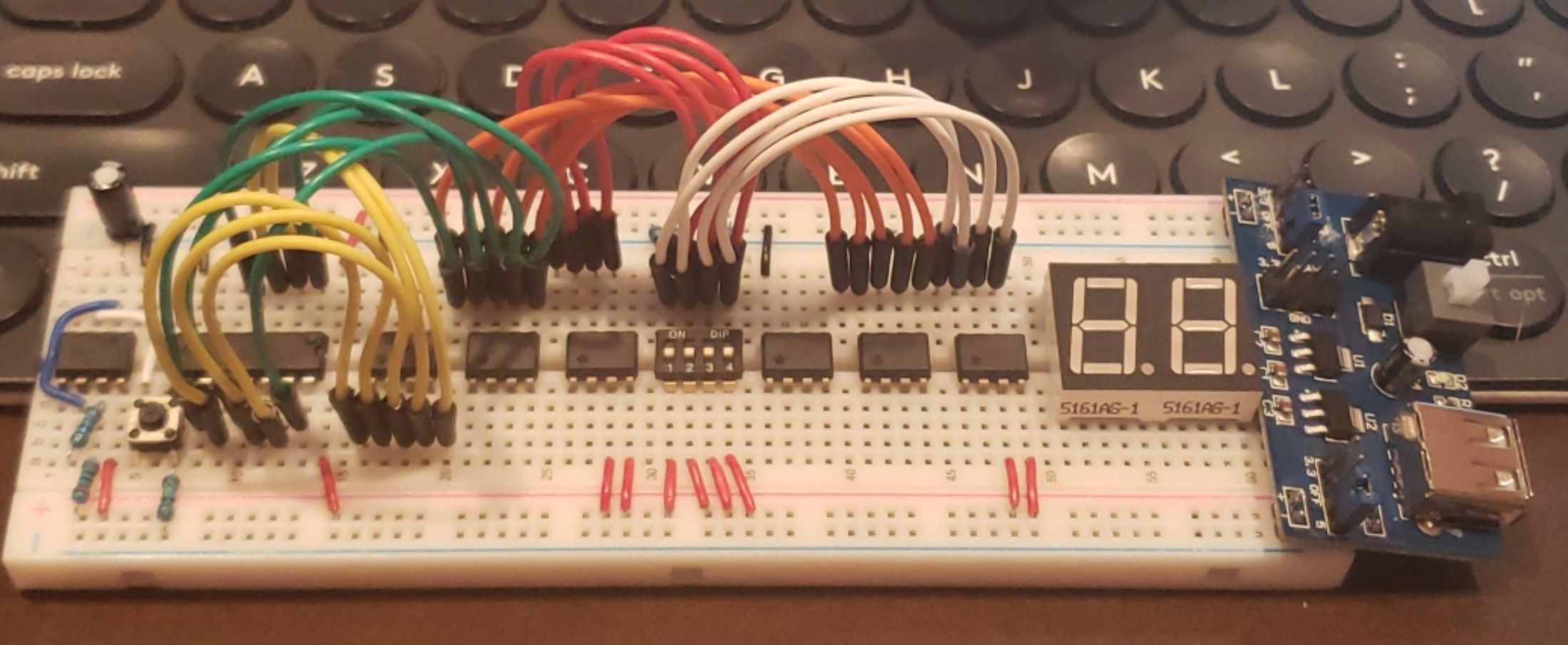
my seven segment displays came in early
https://i.imgur.com/lziSoMG.jpg when i say this thing is barely gonna fit on the board i reaaaly mean it lol
 upbeat geyser
Bwahaha yeah
bright solstice
i need to get working on making the arduino eeprom programmer soon, would like to have that ready before the chips arrive tomorrow
i reaaly want an excuse to get this https://www.ebay.com/itm/1-Lb-Pound-LOT-IC-DIP-Bag-Logic-CMOS-TTL-ANALOG-etc-SEMICONDUCTORS-NOS-UNUSED/273538814604?hash=item3fb02f128c:g:r2gAAOSwJb9WsuHy

eBay
Mostly DIP but may include SMDs. Most data sheets should be out there for you on the web. The pictures show a typical bag and the other picture us an example of what I bag from.
upbeat geyser
Or join https://tgimboej.org/Main_Page
half reef
@bright solstice what do you mean by them being proxies?
bright solstice
they arent the actual chip, i just put them in the place of the chips that are coming in so i can see how it lays out
half reef
ahh gotcha
bright solstice
More wiring progress
plush gorge
My little project car's getting a body. I'm having it my Mits'ute lol 'Mitsubishi utility vehicle'
signal loom
Im designing a robotics game in the FTC style
Anyone can participate in the design challenge
coming 4/2020
Let me know if you are interested in competing
bright solstice
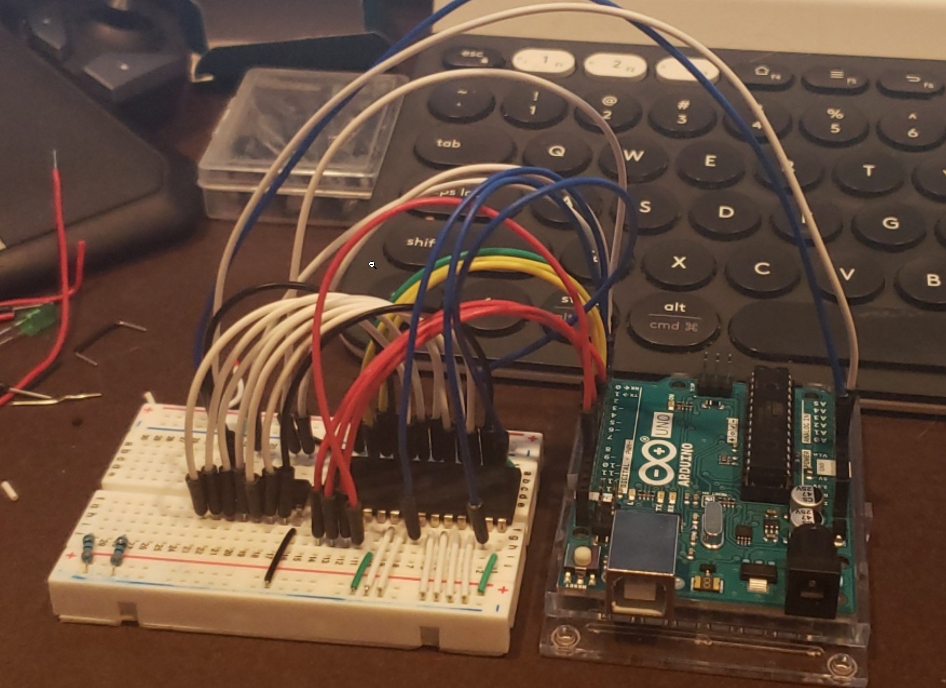
oh dang thats some vehicle
i finally got my eeprom chips, now to see if i can program the things https://i.imgur.com/g4OjOrx.jpg
 topaz flicker
Nice!
bright solstice
im starting to wonder if the write protection was enabled on this eeprom chip... i cant get the darn thing to accept new data 😦
bright solstice
it actually may be that these chips are fakes that dont have any memory and always output high 😦
bright solstice
okay so i think atleast 4 of the 5 eeprom chips i got are fake, and the 5th one is... acting hella weird, i can kinda program it... but it has almost no output voltage at all on a 'high' output... my program may be just hella messed up though, nothing makes sense lol
but the first 4 chips, they send a full 5 volts out of each data pin when set to output, like the more i think about it the less that makes sense, there should be some resistance inside the eeprom chips
this has been a frustrating result for sure, i had beem mulimetering and testing and trying to degug the code of my arduino for 4 hours only for the end result to be most likely these chips are junk 😦
upbeat geyser
Are you sure your PROM programmer is supplying the right voltages and timing?
bright solstice
tbh i cant be 100% sure yet, i sure a heck tried though... but later im gonna do the fully manual version that ben eater made and skip the arduino entierly and see if i get any different results
bright solstice
ok im like 92% sure they are all fake now. i did the whole tutorial for the manual eeprom programmer from ben eater and its just the same dang results. i cant write anything to the darn chips 😦
also i found a forum post about this exact issue
...the 5th chip that i thought was acting weird was because it actually had its vcc pin broken i think this entire time and i didnt notice, so i was just getting garbage from it
i was just getting high-z outputs out of the data pins and my arduino would randomly read them as 1 or 0
https://stardot.org.uk/forums/viewtopic.php?t=11039 the tops of my chips are the same look as the fakes on this page
bright solstice
i mean its either that they are fake, they all have write protection on, or im just derping it up biiig time
well i found an arduino program that is supposed to be able to remove the write protection from these things: https://github.com/TomNisbet/TommyPROM ill give it a go in a few days when my new shift registers come in

GitHub
Simple Arduino-based EEPROM programmer. Contribute to TomNisbet/TommyPROM development by creating an account on GitHub.
 proud ether
Here's my latest project: Kinect-controlled first-person-view mini-mech:
https://www.instagram.com/p/B9dUeXoBX3Q/

Instagram
265 Likes, 8 Comments - Scott Monaghan (@mrpitiful) on Instagram: “She’s got claws... and she knows how to use them. ALICE is an #FPV mini-mech Powered by #Kinect…”
signal loom
I started to make some nice posters out of the CAD I did for robotics this year
bitter hazel
@proud ether how did you interface with the kinect?
bright solstice
made a manual eeprom programmer, only does first 8 address bits though https://i.imgur.com/uBdLjvl.jpg
 bright solstice
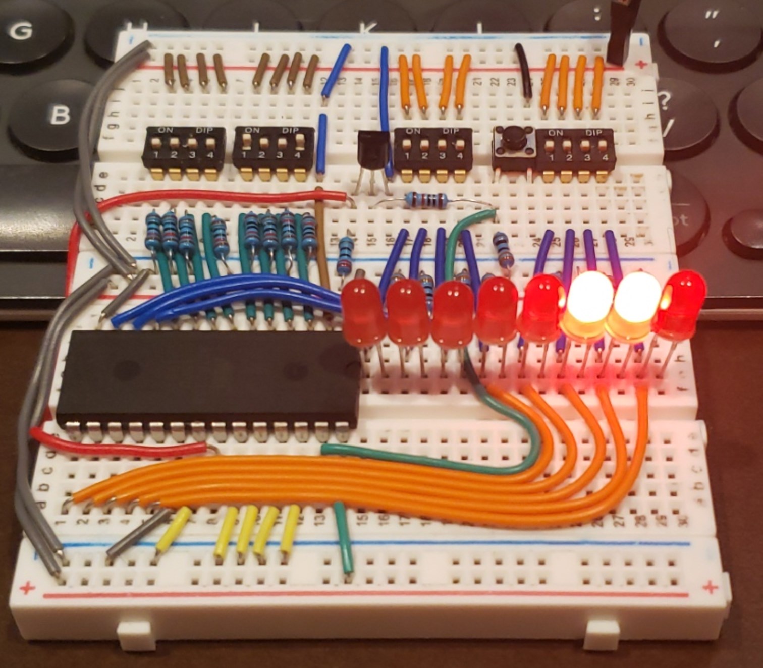
the new and improved EEPROMgrammer 1.1 allows one button press to cause a write, and otherwise always outputs 🙂 https://i.imgur.com/Uw5rIH7.jpg
 proud ether
@bitter hazel I'm using the Kinect v2 SDK and then I connect to my CircuitPython board over serial.
You can see the code here: https://github.com/scottmonaghan/alice

GitHub
Code for Alice, the kinect-controlled mini-mech. Contribute to ScottMonaghan/Alice development by creating an account on GitHub.
bitter hazel
cool. i see you still need a .net service running on a windows box somewhere to talk to the kinect. i was hoping there would be a way to communicate to it directly from the circuit python
proud ether
@bitter hazel That would be so cool!
upbeat geyser
You don't really: it's been reverse engineered. https://learn.adafruit.com/hacking-the-kinect/overview
proud ether
@upbeat geyser cool! For my project I'm going to stick with the least complex option, but @bitter hazel there ya go!
upbeat geyser
Heh, I've never considered .Net to be the least complex option
bitter hazel
nice. they've even decoded the commands. i would still write in c# though as i miss it dearly (we've had to take a bit of time off from each other but we're still in love with each other) its just the need to put it on a windows box that's annoying. there was a gamestop in our area that was finally closing and i did ask if they had some kinect sensors for sale but they told me microsoft has stopped making them since 2017!
if i can find them for cheap in some thrift store for like 10 bucks id probably get one just to try this out
upbeat geyser
Microsoft never made them. Primesense invented and produced them, they were just branded microsoft.
bright solstice
Huzaaaah! The eeprom-based randomizer works! Nearly finished tidying up the wires but I'm tired lol
Once I had the eeprom chips programmed and the octal latch arrived, it just slotted in and worked immediately. Somehow the wiring I did a week before I even had the chips ready was done correctly
Did 200 'roll's and got an average of 10.565, pretty darn close to the correct average of 10.5
upbeat geyser
Slick! Well done!
bright solstice
Haha thanks man, now I just gotta figure out what project to do next. I'm getting some at28c16's in a few days (ordered em before I was sure the 28c256's worked) so I could shrink the project down 4 pins, but I dunno if I want to deal with redoing all that wiring anyway lol. Probly just gonna leave this board as it is once I finish replacing the 'tall' wires
I'm getting 4 knockoff Nanos in a few days too so maybe my next thing will use those
upbeat geyser
My DIP packaged FRAM chips just showed up today, I'm looking forward to playing with them in my breadboard computer.
 fair plover
Frim Fram?
bright solstice
pictures of breadboard computer?
upbeat geyser
It isn't much, yet...
fair plover
I hope that's not contagious! ;)
spiral crest
a veritable rats nest of wires 😄 all the anodes are done for the 16 segment displays; then I have 10x 7 segment displays to wire up
 native rivet
https://gearx.org/ just went live with our open design for a portable, printable, magnet generator yesterday. Our team of devs is growing, and we'd love you guys to get involved! The full assembly and current hardware list is free to download and if you want to make a regular commitment we also have our own Patreon https://patreon.com/gearx . Thanks guys!

gearx.org
Gearx is the first open design for a portable, printable, magnetic generator. Download your free assembly; start developing or become a core developer on our Patreon.

Patreon
fair plover
Someone needs to make 8/16 segment LED displays, but with some sort of serial communication rather than individual LED control! Something like an 8-bit WS2811 or other standard protocol. Too many wires!
upbeat geyser
Et violà! https://www.adafruit.com/product/1911

Display, elegantly, 012345678 or 9! Gaze, hypnotized, at ABCDEFGHIJKLM - well it can display the whole alphabet. You get the point. This is a nice, bright alphanumeric display that shows ...
fair plover
OOh! Full alphanumerical led displays!
NOICE!
(Some assembly required)
Why is it limited to 8 "backpacks" in serial per i2c channel?
upbeat geyser
Every device sharing an I2C bus needs a different address (so they'll know which one is the recipient of data). I suspect they only have 8 different possible addresses. You can get around this with either multiple I2C buses, or an I2C multiplexer like https://www.adafruit.com/product/2717
fair plover
As annoying as the WS2811 timings are, it's a beautiful "protocol" for passing along data to "next-in-line" and is nearly infinitely extendable.
And whereas the WS2811 are 3 bytes, these LED displays would only need 1 byte each.
AND you'd only need 4 pins per led.
upbeat geyser
The SPI(ish) ones are pretty extendable too, and aren't timing dependent (you can run them manually with a couple of switches if you wanted to). However, they take 2 signals (clock and data) instead of one. They can also go much faster than WS2811 or I2C.
I'm unclear where you're getting 4 pins per LED.
bright solstice
yeah its a 14 segment led, though 14 pins sounds like madness so its gotta have some sortta decoder thingamajig
fair plover
Mad: I was envisioning a 8/14 LED display controlled by a chip similar to the WS2811. Vin, Vgnd, DIN, DOUT
But yeah, SPI would be better and more standard, only adding one extra pin for clock
Imagine if each "digit" of this had its own controller, how FEW wires you'd need to make it run:
https://hackaday.io/project/169632-7-segment-display-array-clock

It's an digital clock made out of 144 7 segment displays controlled by an arduino nano.
upbeat geyser
I did manage to get a single HT16K33 to run 3 alphanumeric displays, 10 digit displays, a few LEDs, and a keypad.
fair plover
Are you building a flux capacitor interface?
upbeat geyser
Funny you should ask.
fair plover
LOL!!!!!!
The advantage of the WS281x protocol is that it is "use and forward" and address-less. Theoretically infinite in number of nodes (apart from timing constraints) But limited by the speed that the ICs can grab its signal and keep forwarding the rest down the line.
Adding a clock line can make it faster, no? While still being address-less.
Ooh! SPI daisy chained? Would that work?
lucid bloom
I upgraded the speakers on my pi3+vt220 music terminal (it does other stuff to I have an IR remote that launches/kills programs, does volume, etc)
upbeat geyser
Ah, that brings back memories!
lucid bloom
I'm thinking of retrobrite ing it
upbeat geyser
Yes, the synchronous LED strips like DotStars work like that https://www.adafruit.com/product/2328
lucid bloom
It came from the accounting department of wgbh which is the public broadcasting station in Boston. I got it from the rhode island computer museum, it's technically on loan
But they had 6 others when I got it so I don't think they will need it anytime soon
upbeat geyser
Makes sense. I wish I still had my RetroGraphics "VT-640". I think I still have a VT-510 somewhere, along with the demo ROM that lets you play games on it.
lucid bloom
I will add the leds that's a great idea
upbeat geyser
I was meaning the LED comment to @fair plover but yes, you could echo that bar graph display with LEDs too.
lucid bloom
This is the serial hat that I am using which breaks out some of the gpio
upbeat geyser
I was wondering how you were accessing/converting the serial data from the Pi.
lucid bloom
I used the cheap little ones before but that hat is much easier/reliable
No need for a null modem like with the little ones
upbeat geyser
Makes sense.
fair plover
I have an old DEC VT-220 somewhere as well. It used to be connected to my Uni's VAX.
lucid bloom
You can emulate that with a pi 😉
upbeat geyser
That would be amusing, having a Pi talk over a serial link to another Pi that's emulating DEC escape sequences and displaying on a monitor. Bonus points for using the composite video output and a CRT monitor.
fair plover
If it's VT220, it's gotta have the smooth scroll text!
upbeat geyser
That always looked cool on the ones with the long persistence phosphor screens!
lucid bloom
You can do it all on one pi
I used to have mine with a computer monitor next to the vt220
fair plover
Pi is too over powered for a vt220
lucid bloom
yea the max baud rate of the vt220 is 19200. it barely keeps up with cava that I use for the music visualizer. https://github.com/karlstav/cava

GitHub
Console-based Audio Visualizer for Alsa. Contribute to karlstav/cava development by creating an account on GitHub.
west zinc
For the 12mm size.
west zinc
Print in place button retainer for 12mm tactile buttons: https://www.adafruit.com/product/1119

Medium-sized clicky momentary switches are standard input "buttons" on electronic projects. These work best in a PCB but can be used on a solderless breadboard as shown in this ...
Inspired by ClockSpring: https://clockspring3d.com

 upbeat geyser
That's slick! Were you still thinking of adding some more LEDs to celebrate a "roll" of 20?
bright solstice
I was, but I'd have to shrink down the board. I can remove 8 pins by taking away the switches I was gonna use for the d6/8/10/12 that I haven't used yet, and by swapping to some at28c16's I got in the mail recently
It was either something like the flashing leds like you said, or have a circuit that slowed down the clock to a stop after you let go of the button, or maybe a vibration motor that activated when you held down the button
I could shrink things even further if I found an easyish to use eeprom that had 16 parralel data lines, or maybe I could use one of the tiny serial eeproms and a serial decoder of some sort, but I kinda have doubts on that saving much on pins
I mean I could reaaaaly shrink things down by using a single nano... But that would be too easy lol
I'd like it to be as small as possible without actually using a processor lol
The Fram chips would shrink things down a lot just cause I don't have to use the octal latch but gahh the spendyness of the things :(
upbeat geyser
Yeah, they're like $12 apiece. The 555 circuit for the slowdown is reasonably compact and would be a nice visual effect.
bright solstice
Yeah theoretically the best would be a Fram chip with 16 data lines but I dunno if that's even a thing
 queen solstice

hello
#invention
#robot
#raspberrypi
 clear surge
Love that Burke!!! A+
queen solstice
thank you @clear surge
sharp comet
@queen solstice that is hilarious! Do you have the code online anywhere?
queen solstice
@sharp comet I'll put it in the explanation video that I'm making right now
upbeat geyser
@bright solstice While I'm unaware of a 16-bit FRAM chip, you can always use two 8-bit ones and parallel the address/control lines (this is the usual approach). However, given your space constraints, the pin duplication would be onerous. You might be able to design a little DIP carrier board that carries 2 8-bit SOIC FRAM chips with their leads already paralleled, yielding a DIP packaged 16-bit FRAM, but I doubt a custom PCB is really an option for this project either.
bright solstice
yeah that sounds pretty spendy XD its not like this project is critical, i mean it already functions lol
upbeat geyser
The other approach is to see if you can cram all the functionality into 8 bits somehow.
Or use your PROMs in a multiphase approach, so (for example) address 0x0012 rotated to 0x0112 and 0x0212 and 0x0312, and each phase did different things with its output bits. It's wasteful of address space, but you have a ton of unused address space to play with
bright solstice
yeah if i could somehow control 2 7SD's with one eeprom chip... hmm maybe with another d latch....
upbeat geyser
There are BCD to 7 segment decoder chips. And the latch trick is how some early CPUs (1802, 8008, etc.) implemented a wider address bus than the chips had pins to support.
bright solstice
oh thats an actual trick?
though if i was to do such a trick, i would need at the very least one more address pin, which would mean im using 6 of the output pins to control the input address...
i mean unless there is a magical eeprom that has a 'go to next address' function built in
also since i managed to make the counter, i promised myself i would buy a grab bag of IC's so i did just that haha, hopefully ill learn some cool stuff just going through all those when they get here
im hoping for atleast a couple binary adders and counters in the bag
actually if i get a binary counter i could possibly skip the one d latch i have... and be able to do the circuit with a 8-bit latch, a binary counter, and one eeprom chip
...maybe
...hmm probly not actually
...actually wait i may be able to
sharp comet
@queen solstice awesome, I'll keep an eye out for it! Thank you
spiral crest
powered by my skin :)
unfortunately i can't draw enough current to power the led brightly continuously so i charged up a 100uf capacitor ahead of time and discharged it with the led.
my body apparently is 16V 32VAC above ground
spiral crest
full wave rectification of my body :) lol
 lapis jasper
Here is my show and tell for today! Old zenith transoceanic royal 3000-1.
 humble plaza
full wave rectification of my body 🙂 lol
@spiral crest Try using a BJT!
 bright hull
just to throw this up, stemma breakout mounting holes mate nicely with pi camera (m2 screws), fun mashup of mlx90640 ir cam with pi cam
spiral crest
no point, i'm not using a battery 😉
sharp comet
@cunning lava pong achieved. Loving it so far!
 vast drum
Just got this little vintage DL2416 LED display working! Loving the retro glow. I really want this on a watch.
bright solstice
dang that display looks siiick, i almost want to pick one of those up myself now, they only like 16 bucks on ebay
vast drum
^ me 4 days ago 😂 yeah can't wait to build something with it. next step is getting it working with fewer pins using a shift register or i/o expander
bright solstice
4 digits also would be perfect for a yugioh life point counter my friend really wants me to make lol
vast drum
if you only need digits and not alphanumeric & still want that retro look for cheaper, I also found these old National Semi NSA1166 displays on Jameco for only $2.50 a pop https://www.jameco.com/z/NSA1166-National-Semiconductor-LED-Display-7-Segment-Red-0-10-Inch-6-Digit-1-65V-5mA-2-Inch-Long_2210976.html
haven't hooked it up yet but also looks cool 🙂 digits are a bit smaller though
(can you tell i'm on a retro LED display kick)
bright solstice
need a picture to see what those lit up look like
vast drum
👌 will post one, probs tomorrow night
bright solstice
but 6 digits with a lot of wasted space on the sides deffo wouldnt work for me
vast drum
yeah it's a bit of an awkward package
you can tell some wiseguy at National Semi thought "ooh we'll save a bunch of money selling a 6-digit version by reusing our 9-digit package rather than making new ones!" .....and 40 years later, they're still selling the surplus
bright solstice
lmao now it makes sense
vast drum
there are also (presumably) knockoffs of a slightly smaller version of the 2416, the HDPL-1414, on AliExpress for like $1 https://www.aliexpress.com/item/4000374284086.html?spm=a2g0s.9042311.0.0.73234c4dmltP5n
bright solstice
how much do the actual 9-digit ones cost i wonder
vast drum
i'll tell you in a month if the 1414 works 🙂
tried looking for a 9-digit one with no success... they're probably out there somewhere though. could probs pull one out of an old calculator or something.
bright solstice
knockoff siemens displays eh? hmm
vast drum
i guess the HDPL ones are actually Broadcom, there are a few companies that make/made these "intelligent displays" in a few similar form factors
vast drum
^yep
"intelligent" because you send them 7-bit ASCII char codes rather than having to worry about the individual segments
bright solstice
whats the difference between the 1414 and 2416? one is inteligent?
vast drum
i think just form factor/pinout. 1414 is a bit smaller. they are both intelligent i believe
vast drum
the digits are smaller, but they are similar size packages. i guess the 2416 is a bit wider (1" vs. .7") but same distance between the pin rows (0.6")
bright solstice
yeah the 2416 kinda looks cooler i think
if im not gonna save pin columns with the 1414 anyway...
vast drum
1414 is 12-pin while 2416 is 18-pin, but the extra pins on the 2416 support some extra features that you can ignore & tie down the extra pins
bright solstice
though i just found this version of the 1414 that looks pretty sick https://www.ebay.com/itm/LITRONIX-SP5-14-DL-1414-Intelligent-Display-16-Segment-Red-New-Item-Quantity-1/372984990172?hash=item56d7a349dc:g:KasAAOSw4Kdeanm7

eBay
Find many great new & used options and get the best deals for LITRONIX SP5-14 DL-1414 Intelligent Display 16-Segment Red New Item Quantity-1 at the best online prices at eBay! Free shipping for many products!
vast drum
yeee i saw a few of those on ebay too. love that look with the exposed traces
bright solstice
got those cool gold wires going about it
yeah thats the term, im still a noob at this stuff XD
i only got into this hobby like 3 weeks ago haha
vast drum
vast drum
& that's ok, i feel that way a lot 🙂 i've been doing some form of electronics off and on for a long time, but only as a hobby & never got a proper EE education heh. always feel like there are lots of deep things i know and lots of basic stuff i'm clueless about 🙂 that's why i love communities like this
bright solstice
nahh its 9 pins wide i see now
but that one is so sick looking, and the gold could totally go with the series 1 yugioh egyptian look
vast drum
yeah dude. love that look. hide my credit card lol. already spent too much on components this month 🙂
heading to bed. good luck going down the LED display rabbit hole 😂 ✌️
bright solstice
lol night man
upbeat geyser
For some reason there was a boatload of these odd displays with 7 7-segment digits along with some indicators. I bought 200 of 'em for a few bucks. Anybody want some?
bright solstice
200 of them for only a few bucks? dayum
whats the other side of that thing look like?
upbeat geyser
About like you'd expect
It's a Rohm LS-2074M2G
They're also used as the display in Lee Hart's "6502 badge" project http://www.sunrise-ev.com/6502.htm
signal loom
Those are neat. How much do you want per unit?
bright solstice
id say i want some but i have no idea what id do with em XD
signal loom
Im gonna throw em into my control box for our robots
upbeat geyser
I'm not looking to make money on them, I just have more than I need (200 was the minimum order).
bright solstice
lol how much was the actual cost for 200?
upbeat geyser
It was a while back, like $40 or so, maybe?
signal loom
How are they to program? Is it just 2 pins per segment?
Im still learning 7 segment displays
upbeat geyser
The digits are multiplexed (like many digital displays), so each segment is at an intersection of "segment select" and "digit select" pins. The individual LEDs are pinned out separately, however.
west zinc
https://youtu.be/5gk06Rwm4pc
The LED cylinder tower lives!
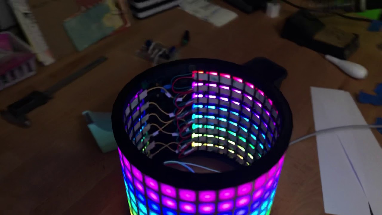

I got the LED strips soldered and inserted into the cylinder. I printed retainer strips to keep the LEDs in their slots. It’s now wired up to the Adafruit Feather Huzzah32 and now running a rainbow trial. I taped two sheets of paper to make the diffuser. Not perfect but pret...
vast drum
awesome @west zinc ! looks really great esp for such a simple diffuser! https://1.bp.blogspot.com/-XisgnoK1TOY/VkX3n_5sUmI/AAAAAAAAkSY/ZBu9LSDKRxA/s640/JOHN%2BTRAVOLTA%2BSATURDAY%2BNIGHT%2BFEVER.gif
 west zinc
Thanks! I made a ring LED clock with a paper diffuser and it works well enough. One lesson learned: use rubber cement to glue the paper to the LED matrix dividers. White glue will make the paper crinkle. But rubber cement-flat paper! Here’s the clock, the video doesn’t do it justice:
bright solstice
Okay, one pound is a looot of chips
would anyone be interested in a stream of an absolute noob going through all of the chips in this bag and looking up datasheets and such? lol
bright solstice
... so the first chip i look at is a telephone tone generator... would it be possible to use this to replicate the old-school dial-up internet sound effects?
its the UM91210
 candid crescent
Probably not quite... the modem sounds include things beside touch-tones.
bright solstice
i thought it might be that the other sounds were just touch-tones with like PWM-ish stuff attached
solar yew
Touch Tones are pairs of audio tones. It's a two-note chord for each combination.
There's probably 8 tones in total.
   a b c d
E
F
G
H
__
Ea Eb Ec Ed
Fa Fb Fc Fd
Ga Gb Gc Gd
Ha Hb Hc Hd
Eight tones, sixteen pairs of tones.
Tone-based signalling is for simple addressing and doesn't operate at faster rates needed for real data transfer.
Analog modems are more along the Bell 103 standard (and more recent advances). I think it's 103. Been a while.
The Bell 103 modem or Bell 103 dataset was the second commercial modem for computers, released by AT&T Corporation in 1962. It allowed digital data to be transmitted over regular unconditioned telephone lines at a speed of 300 bits per second. It followed the introduction of...
v.42 v.42bis that type stuff is in the above listing.
bright solstice
okay im actually gonna open this bag on stream, if anyone wants to help tell me what all this stuff is XD https://www.twitch.tv/omaigrundles

Twitch
A noob opening a bag of old integrated circuits #Arduino #Electronics #Derp #Blerp #Hashtags #Hashbrowns
bright solstice
so i went through like between 1/4th and 1/3rd of the bag and this is what was in it so far https://i.imgur.com/8r37uW0.png
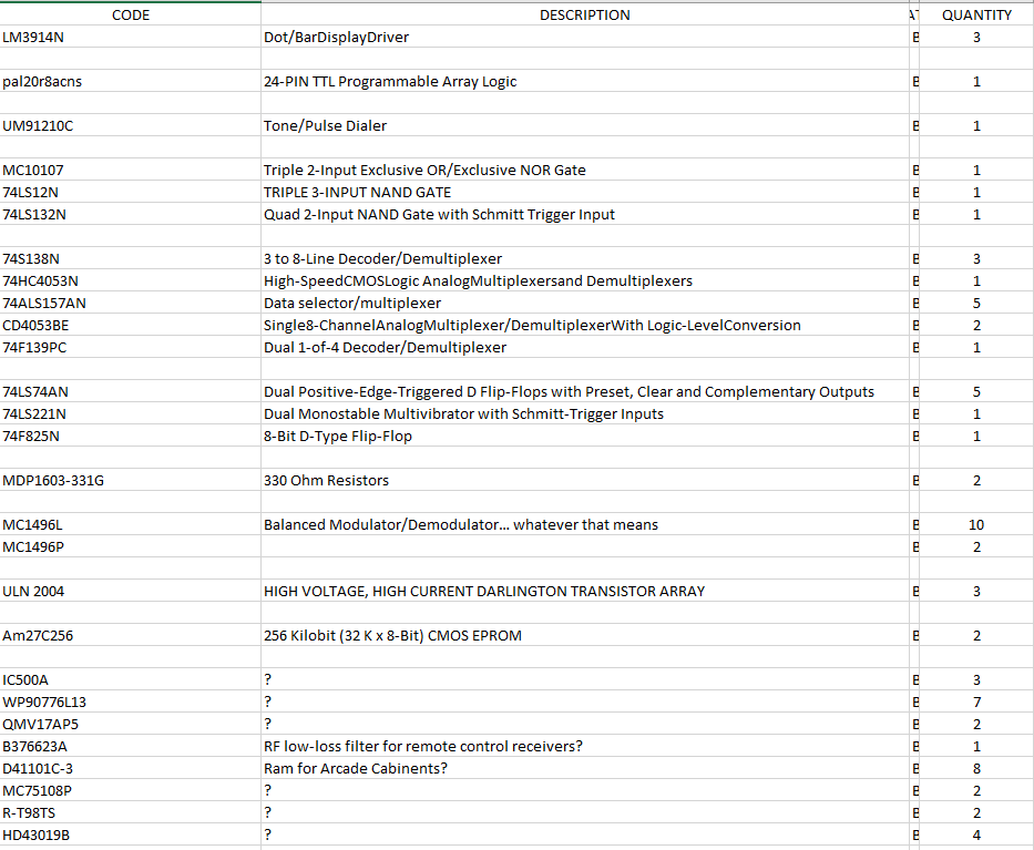
bummed that i couldnt find the datasheet for 8 types of IC so far 😦
topaz flicker
Hope you can find some info on those chips.
upbeat geyser
@bright solstice I think HD43019 is an IR remote control chip, and 75108 is a dual line receiver.
What kind of package is the RT98?
bright solstice
it looks like a DIP-20 package but the pins are Waaaay closer together than my other chips
getting some pics soon
upbeat geyser
Might be a Richtek R-T98TS AKA RT9898 AKA RT9901
bright solstice
yeah though i havent seemed to be able to find much info on any of em lol, though to be fair it would be hard to use this chip anyway cause of how the pins are on it
i didnt even realize it was like that til i looked at it again just now
upbeat geyser
Some info is easer to find than others. You might want to add a "package" column so if people want to help you find info, they'll have more to work with.
bright solstice
yeah im doing that right now
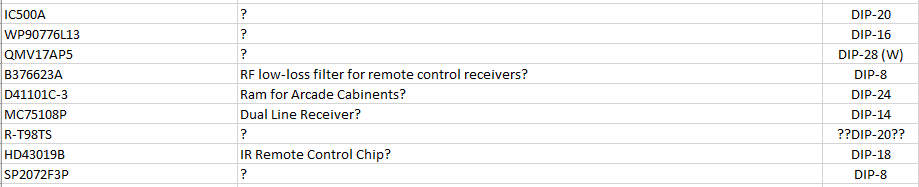
i dunno if there is a specific package name for the 'wide' DIP chips
bright solstice
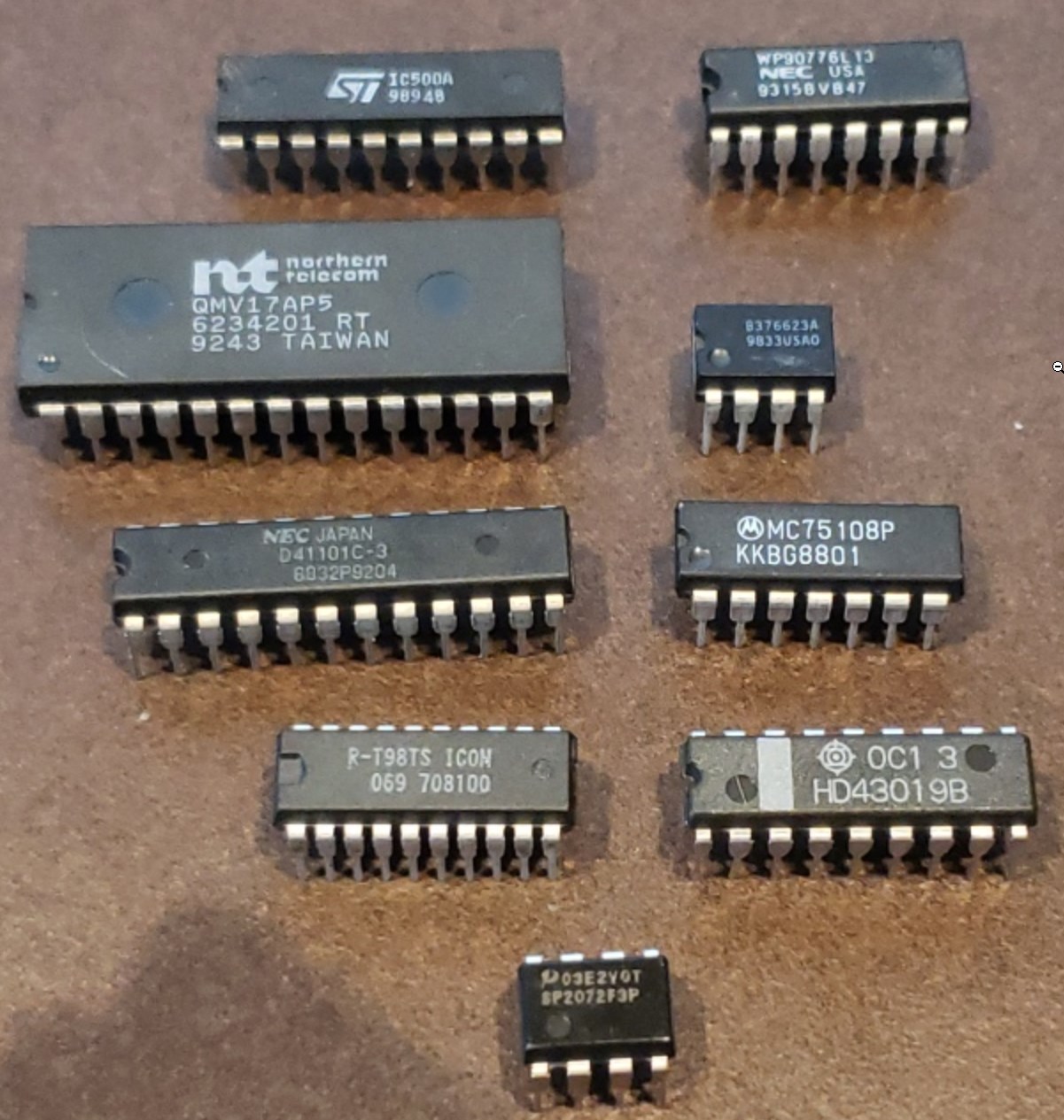 bright solstice
lol i went through some more of the bag, im slowly drowning in NAND gates https://i.imgur.com/suyf587.png

im bummed that i havent found any counters/adders in this bag so far 😦
upbeat geyser
Counters are moderately common, adders, not so much.
bright solstice
One of the chips was described as a 'programmable logic' chip, but I couldn't make much sense of the data sheet, is it like I could use that chip to emulate most of the basic logic gates and such?
upbeat geyser
Possibly!
vast drum
Still playing with those DL2416 retro LED displays... made this little Bluetooth clock by soldering an Espruino MDBT42Q breakout directly to the display! + a Lipo and micro charger. I love this thing, gonna try and make a case for it & turn it into a watch
half reef
@bright solstice i've got no idea if you've already found this but through copious Googling i managed to dig up a datasheet for the D42101C-3
the evidence is pretty much anecdotal but someone repairing an old Snow Bros machine says they were able to use the D41101C-3, which you have, in place of the D42101C-3 that was originally in the Snow Bros machine, and it worked just fine
bright solstice
ooo
half reef
so it might be helpful to you? who knows
i can link it to you in a DM if you'd like, it's a direct download rather than something you can immediately view in browser otherwise i'd link it here
bright solstice
thats actually really great cause i wanted to find out about the ram most of all, i got like 30 of the unknown ram chipx XD
half reef
o.o
bright solstice
https://i.imgur.com/oPUxApi.png nooo these ones are also unknown!
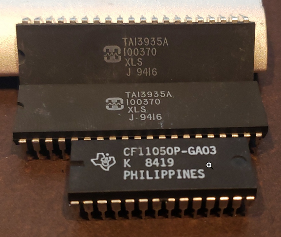
its a dang DIP-40! it might be a processor or even a 16-bit parralel EEPROM! gahh
also finally finished going through the whole 1-pound grab bag. This was the result https://i.imgur.com/pUE6fh6.png
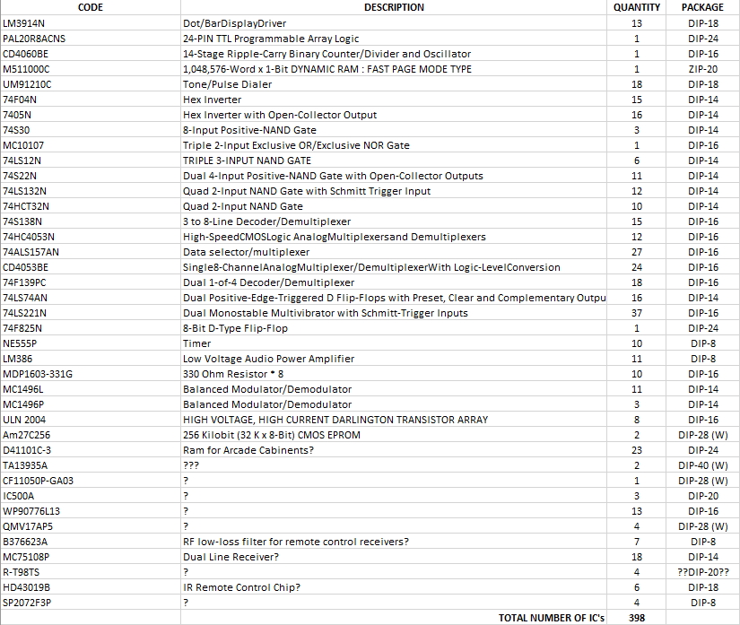
also, i did manage to get one binary counter in the end lol
upbeat geyser
That DIP-40 Harris chip may be house numbered. I'm guessing an OTP CPU but could be all sorts of things.
bright solstice
rock tumbler? more like a rock-flinging minigun
plush gorge
upbeat geyser
I'd use a steady rest for that trick.
plush gorge
What's a steady rest.
@upbeat geyser as in is that the name of tool I hadn't heard of?
upbeat geyser
It's basically a support for turning long thin objects in a lathe without letting them wobble too much.
Those rods in the background remind me of one of my recent projects
west zinc
The cylinder LED matrix hardware is completed and packed for shipment to my brother for more detailed programming. I had to leave a special surprise for him and my nephews when they power it up.
vast drum
took me a minute to see it... now can't unsee ;P
Cool RNG @solar yew !! i've seen a lot of super-complicated TRNG projects and wondered if it could be done with radio noise more simply, as you've done. Nice work - have you done any statistical analysis on the output to prove you've got a nice random distribution?
solar yew
@vast drum great question. Some, I have done frequency analysis on the bitstream. Highs and lows appear with approaches same frequency (within a hundredth of a percent of half duty). I have not ran a diehard battery yet but on the to-do’s.
approximately
vast drum
Cool. The math is above my head, but a bit of googling turned up "SP-800-22", a NIST document which describes some randomness tests, and this github library which implements them https://github.com/terrillmoore/NIST-Statistical-Test-Suite
also, is that a custom PCB you made to tie the breakouts together? I've been considering doing one of those for a project i'm working on with like 4 or 5 boards, it'll be a rats nest otherwise! never done it though
solar yew
@vast drum wonderful! I’ll investigate some of those resources. Yes, I sometimes just build a carrier PCB that provides all the electrical connections between the breakout boards. The next phase will be to produce a PCB with only the components (no breakout boards).
@vast drum you can download my Eagle files from the GitHub repo
plush gorge
@upbeat geyser cool, what was the project? I didn't know the name, but I was just thiking today about making adjustable stands for just that problem. :-)
upbeat geyser
My project was actually a machine learning project to detect defective parts on a production line by looking at them with a webcam and identifying rust and other defects.
bright solstice
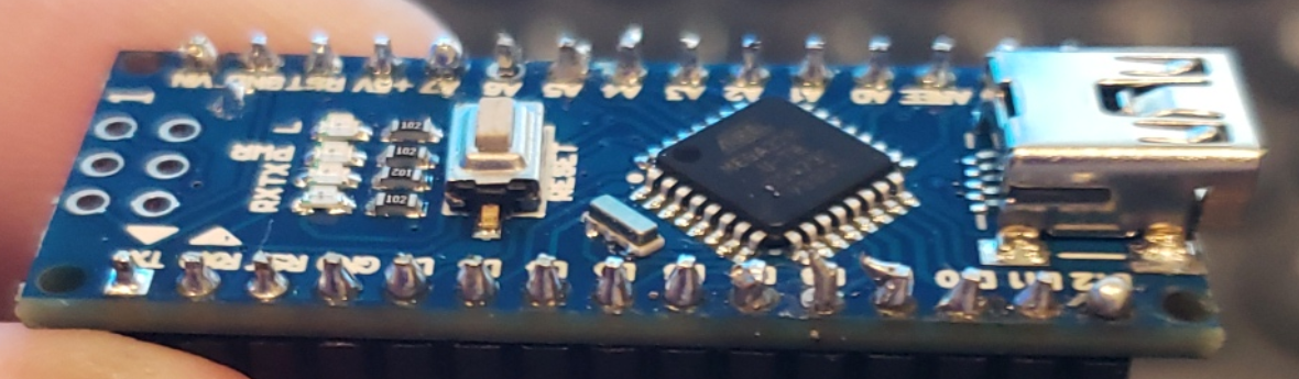
First time soldering, its pretty bad
pin A6 im pretty sure needs to be redone at the least, but this old soldering iron i have is so big and unweildly... and i feel old cause my hands were pretty shaky overall 😦
bright solstice
....though that might also be because i was using a power washer for about 2-3 hours the day before...
vast drum
not bad at all for first time @bright solstice ! A6 & a few others just need a bit more solder. & A7 looks like a "cold joint", just give it a few seconds of heat until the solder flows/wets the pad nicely.
I always get some of those funky "long tails" too but they're easy to fix with a bit more heat or just leave em, NBD. most of those joints look fine.
bright solstice
yeah A6 needs wor for sure
vast drum
def make sure to keep your iron on the pad for a few seconds after melting to get good "pad wetting" ie. so it flows nicely onto the pad, rather than just clumping around the pin
bright solstice
the end of my soldering iron is gigantic compared to these pins though haha
vast drum
i tend to rest my forearm or elbow against the table to fight "shaky hand syndrome" - i gotta drink less coffee 😛
bright solstice
its just a junky radio shack soldering iron, like, is radio shack even a thing anymore?
vast drum
ah. might wanna get a smaller tip. seems like you've done ok with that one though
hahaha no i think they finally went belly up last year. i have an old radio shack iron kicking around somewhere too that i used for years 🙂 finally upgraded to a TS100 last year
@bright solstice just saw your request for iron recommendations in the other channel - i can def recommend the TS100. nice & compact & it heats so fast that it totally changed my workflow. I used to keep my iron plugged in and heated while working & then i'm always worried about the cat bumping into it or something. Now I just do the other stuff with the iron off, & when i'm ready to solder, i plug it in and it's heated 10 seconds later
bright solstice
the tis100 looks nice, also looks way smaller than the behemoth i was using lol
vast drum
yeah i love it, was looking at it for a bit & finally pulled the trigger when Adam Savage gave it an endorsement on his Twitter 🙂
you can go far on an old Rat Shack iron though... & if you get good with it, using the TS100 will be a cinch. It's like how baseball players practice their swing with those big weighty bats 😛
vast drum
yeah they are a bit more of an investment. i used a ~$40 weller iron with adjustable heat for awhile that worked pretty well too. could probs find a knockoff brand for $30ish
I think this is the Weller I have https://www.amazon.com/dp/B000AS28UC/ref=psdc_13837391_t2_B07RZV2DW8
though that photo shows it with a massive tip for some reason
bright solstice
hmm
the ts100 though is pretty much the smallest option you can get though right?
vast drum
it's the smallest overall iron i've seen. you can get super small tips for most irons though.
be careful if you end up shopping for a TS100, many of the cheaper listings do not come with a power supply so you gotta provide your own or pay an extra ~$20 for one with a supply
also you may have seen this already, but this is the best visual description of what to look for in your joints https://learn.adafruit.com/adafruit-guide-excellent-soldering/common-problems
bright solstice
btw i saw this on ebay, seems like a cool idea https://i.imgur.com/qLNrpce.png

oh, that is a good reference, thanks haha, i knew like none of that XD
vast drum
^ that is kinda cool. i haven't really had a problem with TS100 ergonomics but i have small hands 😛
civic vale
That soldering tutorial page must have been interesting to make. Getting a line of solder joints showing all the possible mistakes is hard if you are actually good at soldering, your built up instincts keep pushing you to not do that.
 forest arrow
Hello everyone! I'm super excited to get back into soldering, buying from adafruit, and building more projects 🙂 2 days ago I built an alpha version of the STFU Machine due to my wall-neighbor sleeping at 9pm. https://www.instagram.com/p/B-DghGsnLgI/?igshid=1gwwrn1w3z5ii

Instagram
17 Likes, 1 Comments - Wes Lorenzini (@wes321) on Instagram: ““STFU Machine” Alpha complete! Feel like your music or voice is too loud for your neighbors? Did…”
I did some "hearing tests" with him yesterday to try and gauge how my analog out readings correlate with what he can hear vs not through the sound proofing + wall. I tried 20hz, 130hz, 512hz, 1024hz, 2048hz, 4096hz, and 8192hz with him at various volume levels. After that I needed a solid break since that made me quite nauseous
I also pressed too hard on my 4-Digit 7-Segment FeatherWing Display or shorted it via breadboard after I didn't cut the wires short enough on the inside so lesson learned there!
Micro cutters are on the way!
 bleak lichen
Hey guys, really excited to show off inspectAR for a few minutes longer tonight!! Hanging out on the discord between know and then if anyone has any questions
 hollow hull
I'd like to show a birdhouse with solar powered weather station today
ancient skiff
hi, tuning in as directed 🙂
 lunar venture
does anyone have the join link?
forest arrow

YouTube
To show and share your project at 7pm today, view the chat or in discord https://adafru.it/discord and look for the JOIN link to join. For best results be o...

Engage your Facebook, or YouTube, Live audience with interviews and shows; all the tools you need for professional shows right in your browser.
@lunar venture
lunar venture
thanks
forest arrow
streamyard is for you to show off what product, youtube is for watching.
vast drum
@lunar venture @ancient skiff discussion in #live-broadcast-chat FYI 🙂
ancient skiff
ah my mistake 🙂
 light sundial
anyone know how to get on the show and tell stream?
scenic siren
The SteamYard link. But it might be full.
light sundial
where is that?
forest arrow
Engage your Facebook, or YouTube, Live audience with interviews and shows; all the tools you need for professional shows right in your browser.
light sundial
thanks!
bleak lichen
Hey guys if anyone wants to check out inspectAR you can make the download here https://www.inspectar.com/sign-up-free
Sign up and try inspectAR free version. Access smart datasheets and docs in AR for evaluation boards, open source circuits, and DIY kits for iOS and Android.
Also, if you wanna use us to show and tell your project send me an email at info@inspectar.com. Its a done deal!
bright solstice
https://i.imgur.com/uU6Zo7c.jpg second time messing with the soldering iron, went back over a buncha the pins, and burnt a finger XD
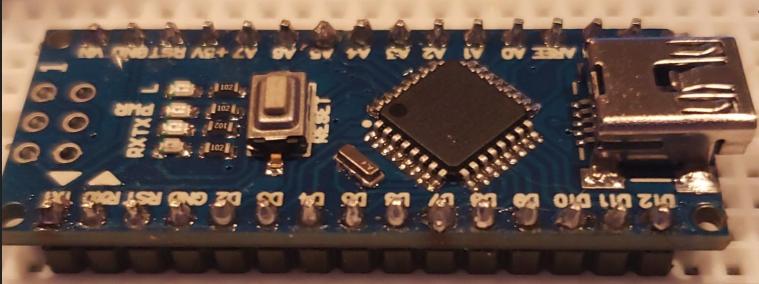 glad sable
looking good!
 plush igloo
crimson egret
plush igloo
crimson egret
This is just a very early code, for showing Covid19 stats in a PyPortal.
https://github.com/fede2cr/pyportal_covid19
GitHub
Using and Adafruit PyPortal to receive daily stats about the progress of Covid19 infections in your country - fede2cr/pyportal_covid19
crimson egret
A bit of work later...
signal loom
I like that. I may make a version that has our total number of masks and face shields produced
vast drum
I ❤️ Tindie kits. just put together this great little AVR programmer shield for tinkering with ATTinies and Megas 🙂
bright solstice
made in oregon? i live there lol
https://i.imgur.com/BBdXPbV.jpg my 'old' eeprom-based d20 randomizer vs a theoretical layout that would shrink it down quite a bit... if i just took the time to wire it and program the eeproms
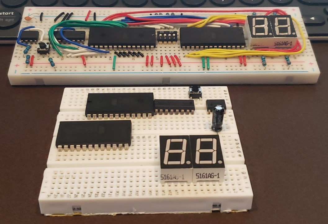
the wiring would most likely be an absolute mess considering im not using a power/ground rail lol
and the fact that one eeprom chip is gonna have its address read in backwards
also since i never used the DIP switches in the original, im just chucking it out on the new layout... though there is room to slap it in theoretically, just to the left of the 7SD's
bright solstice
https://i.imgur.com/lIFIr17.jpg ok just need to get the buttons wired now and code for button presses
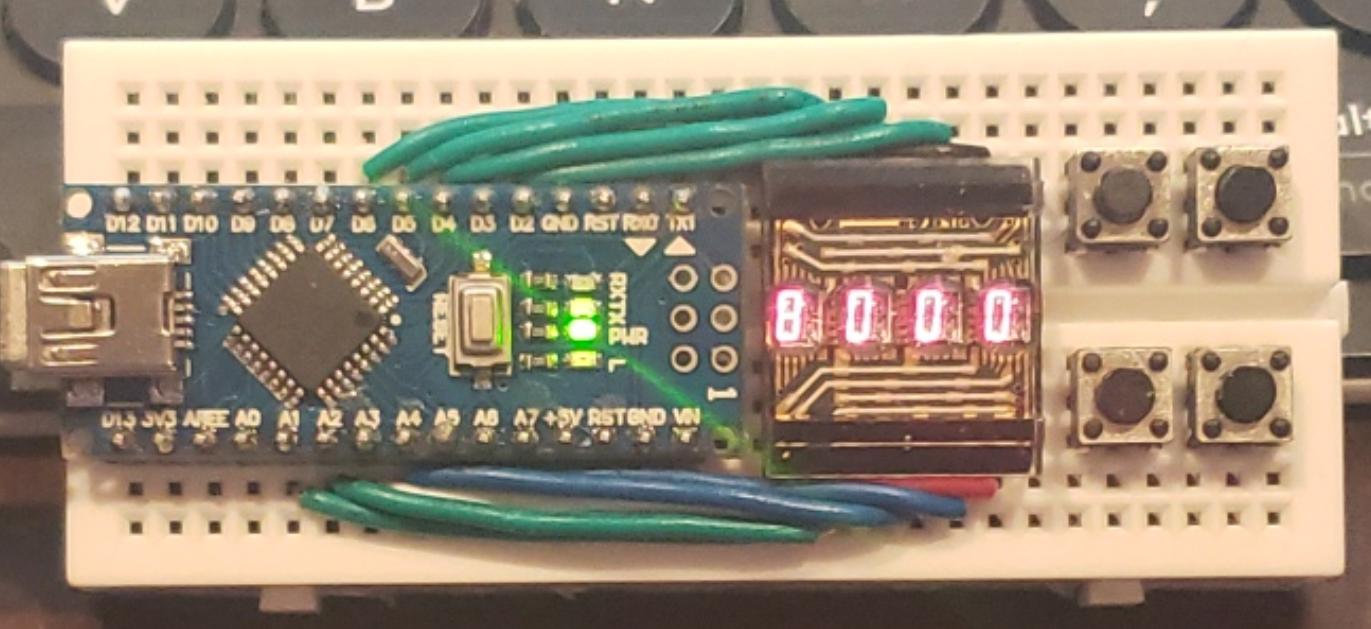 vast drum
yeee looking good after the haircut @bright solstice, nice work!
bright solstice
XD
bright solstice
finished wiring, really happy i was able to figure out a way to slap the resistors on without it looking terrible 🙂 https://i.imgur.com/lNq6EWU.jpg
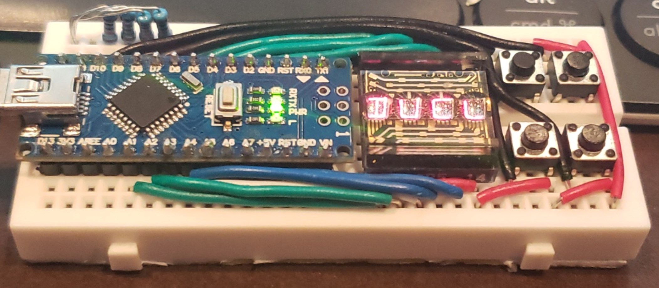 bright solstice
my only issue now (other than taking the time to finish coding) is figuring out how to power this thing... like i need something tiny can power this thing for a couple hours at a time
one idea i had was using a usb-powered 9v battery thing... can a nano accept 9v without releasing the smoke of death?
upbeat geyser
The regulator on a Nano accepts 7-12V in, so should work with a 9V battery. The information is on https://store.arduino.cc/usa/arduino-nano under the "Tech Specs" tab.
bright solstice
can the nano also accept 9v through its USB port? cause my new idea for powering it is soldering the ends of a 9v battery adapter to the pins of one of these https://i.imgur.com/ofZ1TWa.png
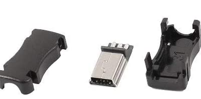 candid crescent
No, I don't think so. There's a separate VIN pin which goes to the regulator, but the USB is straight to 5V on the board, according to the schematic.
bright solstice
ugh, dangit i already ordered this yesturday and didnt think about that til today... is there like some really small like voltage-changer-thingy i can slap onto this?
dealing with voltage is such a pain lol. only reason im doing 9v is because i ordered a usb-chargeable 9v battery replacement, as its way smaller than any powerbank i could find online
candid crescent
Any particular reason you don't want to use the VIN pin on your protoboard?
bright solstice
looks and i wanted to easily be able to pull the plug out to turn the device off
and also i was gonna make a couple extra of these to power nano's easily on future projects. tired of luggin a giant powerbank around
if they sold a 5v usb powerbank in the size of a 9v battery id buy in a heartbeat lmao
candid crescent
We offer wide range of products including phone battery, emergency phone, iPhone smallest, android, cell and travel phone charger at great prices.
bright solstice
huh. that is interesting haha
well the thing is i do already have all the other stuff coming in ugh XD
would this magical-looking tiny device be something i could use to fix all the problems?
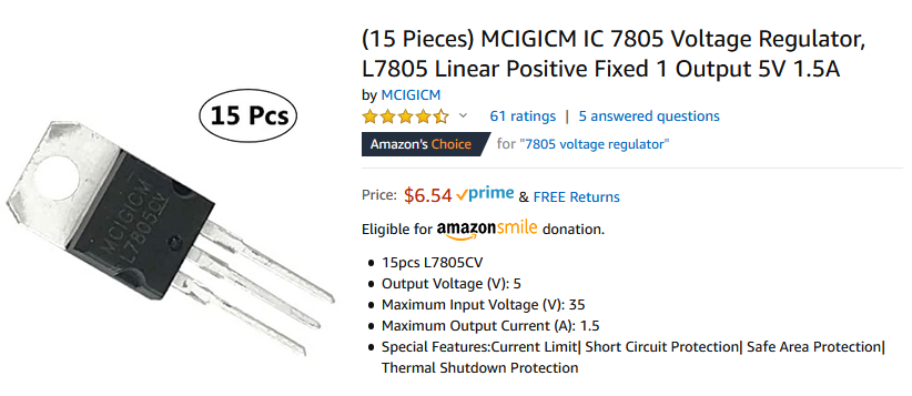 candid crescent
Yes, although bear in mind that it will burn close to half your battery power, since it'll dissipate the difference between 9V and 5V.
bright solstice
ohhhhh
does the arduino do the same thing to the power that comes into its vin pin?
candid crescent
Yes, it does. Simple linear regulator, looks like.
bright solstice
oh dang, thanks for all the info so far, man electricity is complicated
what would it take to not waste the power?
cause that '9v'(apparently tests on the one i ordered only outputs 8.1 v according to a reviewer, so thats kinda good for me) battery only has a charge of 500mah
candid crescent
For that you would need a buck converter, aka DC-DC converter. Those use inductors to change voltages at around 90% efficiency.
bright solstice
is there an extremely small version of this device?
candid crescent
They can be quite small, yeah, depending on the current needed. Recom, for instance, has a line of chips which is marketed as a linear-regulator replacement, so same pinout with better conversion efficiency.
bright solstice
either way though, failure or no on this project, im learning things, and thats the main point i guess XD
i cant belive its not even been a months since i ordered the first parts and started doing things like this
 latent fog
Its a little messy still, but here is my Adafruit Clue - Motocycle datalogger for Track use.
Clue is providing sensor data including a uart gps, this sent to the raspberry pi for packaging, the pi is providing video capture, gpio for the handle bar buttons you see up on the top right, as well as file hosting via wifi
green button turns on the whole system, using the adafruit lipo charge break out board, blue botton arms the data logger and pi camera capture, red button is used to indicate a lap event, my motorcycle has a race ecu that also provides feeds for the rpm, throttle position and bunch of other useful info
additionally I wrote a Qt visualiser for the sensor and video data
its all still a work in progress
upbeat geyser
@bright solstice There are little high-efficiency regulators available https://www.digikey.com/product-detail/en/recom-power/RO-0505S/945-1220-ND/2256400
sharp comet
@latent fog that is super cool! do you have the current progress documented anywhere else online? They are always on the lookout for neat projects like this to feature in the weekly newsletter.
latent fog
@sharp comet I did a you tube video a few days a go, I was gonna do another one in few days showing more progress. What documentation would be appropriate. I'd love to put something together. I'm going to be uploading my code to my git hub including the arduino, rpi scripts and qt application all open for people to grab and use.
after this project I want to make my own juggling balls with an clue like board in, so that people can code them to take advantage of the sensors when designing their light shows.
sharp comet
@latent fog Youtube and Github are perfect. If you put links here for those I can get it submitted for next weeks newsletter.
latent fog
awesome I'll wrap up the software and get it on git hub, I did have some changes to the adafruit libraries locally to add additional sensor types, one for gpio buttons and gps sensors not sure how I go about sharing these I guess I could make a fork but its a bit heavy weight
sharp comet
Typically way would be to make a fork, add your changes to it and then make a Pull Request on the Adafruit repo.
latent fog
alright I'll look to cleaning that up, or implement those bits in my code for now
thanks @sharp comet
sharp comet
Yep, you're welcome.
latent fog
Here is a video of my project along with the git hub repository for the code:
https://www.youtube.com/watch?v=tLEF2G1SJGI
https://github.com/johnmichaelquinlan/datalogger
Adafruit Clue - https://www.adafruit.com/product/4500
Adafruit Dragon Tail - https://www.adafruit.com/product/3695
Adafruit Micro Lipo USB charger - https://www.adafruit.com/product/1904
Adafruit GPS Active External Antenna - https://www.adafruit.com/product/960
Raspberry PI Zero W - https://www.adafruit.com/product/3400
Camera Cable for PI Zero - https://www.adafruit.com/product/3157
Raspberry PI Camera - https://www.adafruit.com/product/3099
Lipo 3.7v 2000 mAh - https://www.adafruit.com/product/2011
uBlox Neo M6 GPS breakout - although any of the uart gps breakouts on the Adafruit site would also work just fine.

This is a quick update and overview of the data logger project including the analysis software I started writing to look at the data and video.
Find almost everything I used to build this at Adafruit:
Also checkout the code that makes this all wor...

GitHub
motorcycle track datalogger. Contribute to johnmichaelquinlan/datalogger development by creating an account on GitHub.
Do you feel like you just don't have a CLUE? Well, we can help with that - get a CLUE here at Adafruit by picking up this sensor-packed development board. We wanted to build some ...
Sometimes I dream of having a miniature pet dragon that would sit on my shoulder, while I write code and build projects. Maybe its little snorts of fire could even heat up my soldering iron ...

Oh so handy, this little lipo charger is so small and easy to use you can keep it on your desk or mount it easily into any project! Simply plug it via any MicroUSB cable into a USB port and ...
sharp comet
@latent fog Really cool! thank you for sharing 🙂
latent fog
next steps are get this in a box and mounted on the motorcycle and take for a test spin, then add more functionality to the analysis software like a google maps with a gps path traced over, lean angle analysis or 3d model orientation.
Then I have some feeds from my ECU that are 5v analogue signals I need to get into the clue for throttle position, rpm
I could even add wheel speed sensors with an encoder or magnet / induction sensor, sespension travel with linear potentiometers
 pine perch
How do you join show and tell

Adafruit Learning System
Show us what you are working on weekly on Adafruit's Show and Tell broadcast
 lusty siren
It's not electronics, and I've been kinda away for a while now, but: I've started making dice and today inked a set with glowy numbers. I'm certainly enjoying myself with these.
https://twitter.com/jollyrollerdice/status/1245904713800912897

Didn't have a chance to make Glow In The Dark dice (Don't worry, I'm going to make them!), but I DID ink these ones with some paint I mixed up and works!
#handmadedice #dice #glowinthedark
 Twitter
 tired walrus
Hi. I recently joined Adafruit world. Circuitpython caught my interest for some time and I bought CLUE so I can reuse stuff I have for micro:bit. Controlling Strawbees crane is my first project. I have very little free time so movement isn't polished. I can send code if someone is interested. Here's video of crane in action: https://drive.google.com/open?id=1ZTBG4MrLfJgD2YA4Yma-N0Nm0dyjp3TG

Google Drive
scenic siren
@lusty siren I love it!
lusty siren
Thanks! I think they turned out fairly well
lusty siren
A closeup of the dice under more normal lighting. They're amber colored with (rubber) flies in them!
solar yew
How to Make a DIY Alarm Clock With LCD Keypad Shield
https://www.instructables.com/id/How-to-Make-a-DIY-Alarm-Clock-With-LCD-Keypad-Shie/

Instructables
How to Make a DIY Alarm Clock With LCD Keypad Shield: Hi everyone! In this instructable, I'm gonna show you how to make an Alarm Clock using Arduino Board. I've used Arduino UNO, LCD keypad Shield, 5V Buzzer and Jumper Wires to build this clock. You can see the time on the dis...
I hope you guys like it!!
queen solstice

#minecraft #arduino #invention
I know, it's burry.
https://github.com/SmothDragon/FacialDetectionAndLaserDetectionForPlayingGames
 whole horizon

Instagram
28 Likes, 1 Comments - Shane Morris (@modernalchemist2) on Instagram: “A demonstration of how the black mage eyes work. You can see the full video of how I made it here:…”
latent fog
I turned my breadboard prototype datalogger into a hard wired prototype datalogger ready for a box:
the clue and rpi can both be unplugged and the edge connectors on the clue and sides of the pi for the memory card and camera cable are pretty close to where the edge of the box will be so I should be able to make access points for those easy enough
Just gotta stick it in a box, mount it on the bike and take it for a spin
vast drum
awesome looking good @latent fog !! i love that process of reorganizing/compactifying. gotta post another pic when you get it on the bike 🙂
signal loom
Working on a laserable 3D Verk shield design
Stay posted over at https://hackthepandemic.org

Hack The Pandemic
Hack The Pandemic is a driven group of Makers, Designers, and Volunteers that work with healthcare providers to develop PPE to combat the COVID-19 Pandemic
dusk zinc
When the volume buttons on the receiver remote control break, of course you just make a "Pyoneer" volume controller with a Trinket M0 running CircuitPython.
bright solstice
The mostly completed yugioh life points calculator. Includes ability to display higher than 10k, the ability to halve your life, in/decrement by 10, and a 'game over' screen. Timings could be improved for sure, but it mostly works! https://gfycat.com/determinedgentleflycatcher

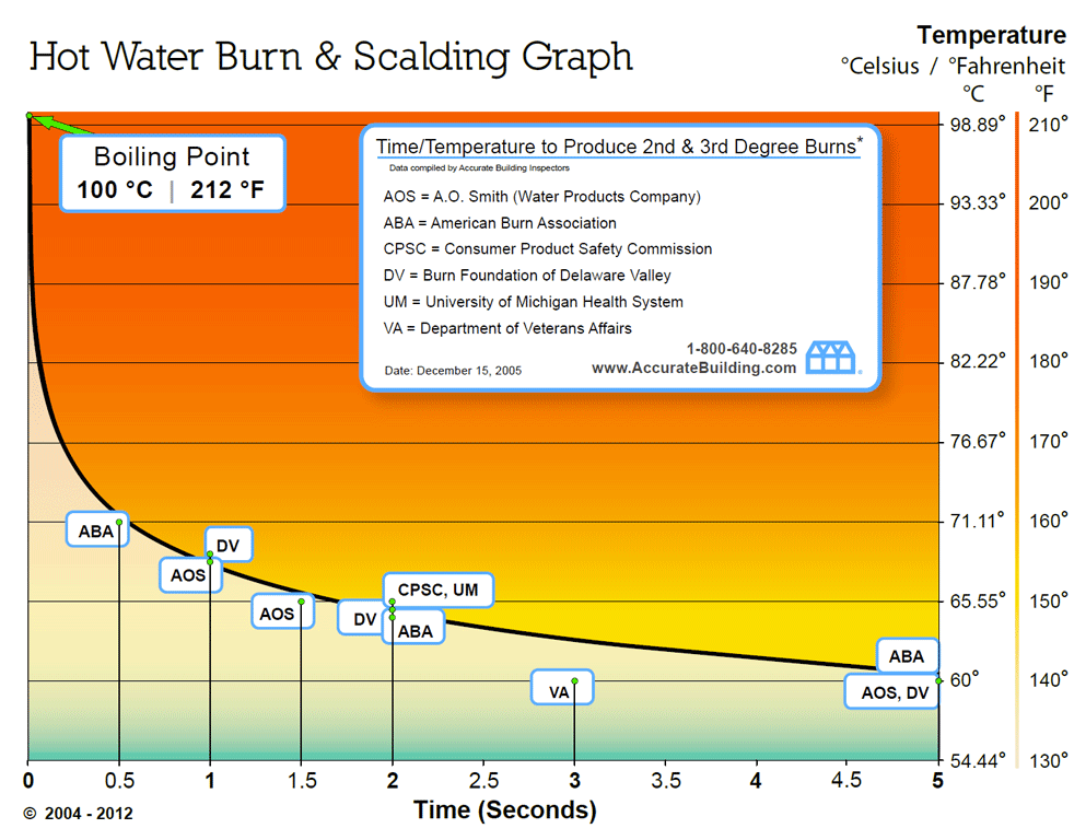





i didnt use any libraries to control the display, just did all the code from scratch. I want to be able to hit the buttons really fast but also not ever have any accidental second button presses, but its a fine balance
i just need to now figure out what to do for the third project 😦
upbeat geyser
My first time generating a VGA signal with an FPGA
My monitor didn't like my first couple of tries, so I finally looked at my horizontal synch signal with an oscilloscope, to see it's way too narrow, maybe 50ns, when it should be 3.8µs or so.
candid crescent
Nice! Which FPGA are you using?
upbeat geyser
ICE40 HX1K on a Nandland Go board.
bright solstice
niice
torn viper
yay @upbeat geyser
one of us... one of us..
nandland has a lot of great materials
I'm currently borrowing his spi slave and fifo for a project
upbeat geyser
Had some issues with IceStorm/IceStudio but worked through them.
torn viper
oh, what were those?
upbeat geyser
Once I've cleaned up my code, I may submit it back to include as examples.
torn viper
the only problem I've had with icestorm/yosys so far is my code being bad and it generating unusable output from my unusable code haha
upbeat geyser
With IceStudio, if I started with the Go board, it would fail with a bogus "FPGA I/O ports not defined" error. The workaround is to select the Alhambra board (adjust the pins), build, then switch back to the Go board (re-adjust the pins), then it builds successfully.
upbeat geyser
The Nandland example code wouldn't build because it's (apparently) a different VeriLog dialect, so I ended up rolling my own.
It's a nice little board to get started on, I like it.
torn viper
cool
upbeat geyser
I may pick up an IceBreaker once they're back in stock at Mouser.
torn viper
yeah, I started with an intel de10 nano and now I'm working on a project targeting tinyfpga
upbeat geyser
After fighting with the Xilinx and Altera tools multiple times and giving up multiple times over the years, it's nice to have a toolchain that actually behaves and is easy to install.
I actually ordered a TinyFPGA BX back in September, but it never shipped.
torn viper
where did you order it from?
upbeat geyser
I ordered it from tinyfpga.com
torn viper
I'm getting mine from sparkfun
upbeat geyser
I just brought up the order status page, it still says "You'll receive an email when your order is ready"
torn viper
maybe find luke on twitter or something
upbeat geyser
I sent him an email a few weeks back, but no reply.
torn viper
bummer
I wonder if he got a bunch of distributor orders and couldn't fulfill his direct orders or something
upbeat geyser
I figured that or it somehow slipped through the cracks.
torn viper
yeah
maybe it got lost because it looks like he's not selling directly through that site anymore
like in the shuffle from direct orders to crowd supply orders
upbeat geyser
That does sound logical, but I'm unsure what to do about it.
torn viper
complain on the internet!
upbeat geyser
I guess I could sign up on the TinyFPGA Discourse and ask there.
 prime zephyr
Got mine through CrowdSupply. They show in-stock there. https://www.crowdsupply.com/tinyfpga/tinyfpga-bx
 upbeat geyser
They're in-stock at several places, but I already paid for it
prime zephyr
Charged the card then never shipped? That's always irritating. Likely too late for a card complaint too. At least it's $40 not $400...
solar yew
IS this show & tell?
half reef
show and tell actually happens in #live-broadcast-chat if you didn't spot it already @solar yew
this channel is for showing off your creations any other time
 round zodiac
I made a PyBadge metronome in CircuitPython. This is my first useful creation with PyBadge and CorcuitPython. Source code is metronome.py at https://github.com/gmeader/pybadge and a demo video is at https://youtu.be/ICGBr8tG5b0

GitHub
example code for Adafruit PyBadge. Contribute to gmeader/pybadge development by creating an account on GitHub.

A metronome app written in CircuitPython for the adafruit PyBadge
Source code is on http://github.com/gmeader/pybadge
scenic siren
@round zodiac Thanks for sharing! I sent it to be added to our Python for Microcontrollers newsletter that we do each week.
lucid bloom
It looks like a normal Adafruit box but in fact it is a wardriving rig with custom .kismet to .kml scripts, 2 USB wifi cards, Bluetooth dongle, pijuice battery pack, berryimugps, gps antenna, USB drive and a button. When you are done driving you push the button and it generates the maps and puts them on the USB drive. After the car has been off for 10 minutes it will shutdown and wake when the car is started
I split the project in 2. I have a war walker that maps open hotspots, connects to them, does the captive portal and then speed tests the networks. What the war walker does doesn't work at driving speeds
https://github.com/fruitybug/fruitygis
This is the script I modified and made several versions of
It was a very fun project and fun to test.

GitHub
kismet to kml (new version kismet sqlite to kml). Contribute to fruitybug/fruitygis development by creating an account on GitHub.
 proper dirge
Not sure where to put this, but it was pretty cool that Creality sent me five n95 masks.
Whether or not they make me safer, it gives my mom peace of mind when I deliver her groceries.
 lone saffron
scrounged some neopixels, a feather, and some foam core together to make a heart for the window
sharp comet
@lone saffron Very Nice! Do you use CircuitPython on the Feather to drive it?
lone saffron
we ended up using arduino- will be testing the Bluetooth control a little later tonight
I do want to start messing with circuit python though- maybe this is the chance...
upbeat geyser
Playing with Lectron, got this 2-transistor amplifier to oscillate in interesting little peeps
 ivory prism
holy heck haha thats crazy
its like circuit lego
 rough patio
A little musical snippet made with a Teensy 3.6 Arduino on keys and DIY modular synth doing beats https://www.youtube.com/watch?v=DS6oFbQnCGg

Using our #stayathome time to get stuck into digital signal processing! The teensy 3.6 arduino runs a polyphonic triangle patch made with #FAUST Functional Audio Stream and the teensy audio library, controlled via MIDI with the arturia keystep. The sound is then run through th...
upbeat geyser
@ivory prism That's what I learned electronics on, it's great to use. They're little clear blocks with components inside and the schematic symbol printed on top, so when you arrange the blocks into a schematic, you've built that circuit. While there are similar systems out there (Snap Circuits, LittleBits, Gakken, Brick-R-Knowledge, etc.), I like the Lectron approach the best.
 jovial pilot
Made a lil' toilet indicator to let me know when the bathroom is free, using a servo, a neopixel, Airlift, and Adafruit IO.

Cute as a button, this lil' internet-connected, miniature toilet model sits on my desk and lets me know when the house's only bathroom is free. Equipped with a servo, a NeoPixel, and a ESP32 breakout board, Lou the Toilet glows different colours and raises and lowers its lid t...
round zodiac
I created a new PyBadge CircuitPython app that monitors the USB MIDI port and displays the MIDI clock tempo BPM (Beats per Minute).
Source code is in https://github.com/gmeader/pybadge in the midiclock folder. Test code in Python3 is included to generate MIDI clock messages on the host computer to send to the PyBadge.
GitHub
example code for Adafruit PyBadge. Contribute to gmeader/pybadge development by creating an account on GitHub.
terse totem
@round zodiac that's really great and useful!
latent fog
Finally got a box to fit my project in, I got a box that was too small but looked awesome, this one is just a prototype box that I can take the project out for a spin in.