#show-and-tell
1 messages · Page 10 of 1
 lusty siren
I can read, I swear!
I want to build a Pi-powered Smartphone, It'd have to be a Pi 3, though. Zero just doesn't cut it, capability-wise.
 woven relic
Since it IS Star Wars Day I'll show off my lightsaber I've been working on! I was gonna wait till the next show and tell but I gotta share since @terse totem did a lightsaber build today too.

Google Photos
 terse totem
@woven relic that's terrific!
woven relic
Thank you! the original saber has a board and speaker inside so im using those for the sounds but at some point i may look at removing it and replacing it with an sd card and another arduino type. I currently have a trinket pro in there. The button i use to change the colors is an RGB button so it displays the current color that the saber will light up when you turn it on. but the button isnt completely true to the color thats gonna show up.
 mystic ruin
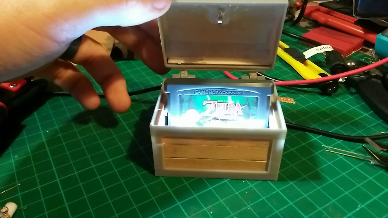
I think I'm finally finished,was a bit of a pain to fit everything in! I should have made it slightly bigger
If you haven't seen me talk about it before its a present for my reddit secret Santa. Its using an attiny85 to play the melody, a normally closed reed switch to turn on when chest is open
And is powered by an old Nintendo ds battery (this is way overkill for this project, even if the cell was now at half capacity it could run for at least 5 hours 😂
terse totem
That looks great @mystic ruin
mystic ruin
Thanks @terse totem !
 crimson knoll
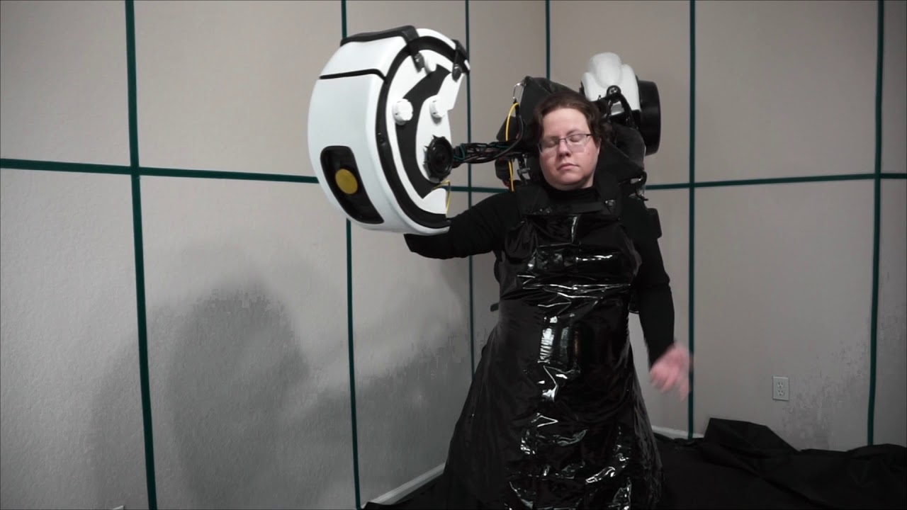
update photo of my GLaDOS puppet project
 stable kayak
Don't trust it when it offers cake.
crimson knoll
heheheh
 edgy stratus
I have one more build log to push to the project, but would anyone be willing to give me feedback on my buildlog/project? I want to get better at documenting my projects so I'd love any feedback!

This trophy will act as our Game Night Group's 2017 Champion Trophy.
 karmic fjord
Ok. Functionally ready for next Wed night. The code needs some cleanup before being published, though.
 toxic yew
One of the main reasons I bought this was for the soldering practice. I guess I proved my need for practice by breaking three of the eight fuse holders.
 rain escarp
Practice is awesome.
karmic fjord
It’s how you develop skill.
 shut sigil
Tip tip, when I press the tip of the soldering iron onto the surface of the copper/pin, I will roll the tip slightly into the pin just prior to applying the solder. It tends to get the heat distribited quicker around the pin. And remember rule of thumb, remove solder and then iron. For me it's a tip-in, roll, solder-in, solder-out, tip-out, all in what, 2 seconds max?
lusty siren
The way I learned to fix things was because they were broken. I'll let you figure out who broke them most of the time
lusty siren
It's often "Oooh, I wonder what's in here!" or "How does this work?"
I can't tell you how disappointed I was at age 4-5, sitting there with a flathead screwdriver and a mangled hotwheels car, disappointed that there was nothing inside
shut sigil
What's this switch for? I wonder what will happen if I just plug it in.
Oh, when my slot cars would stop running. Thats when I figured out what a reostat was and how dc controlled the car.
I thought HEY, more voltage, faster car. Well, for a while, then smoke. Just like the real thing. 😃
lusty siren
Then you take out the motor and put a new one in!
shut sigil
Bingo!
lusty siren
Hm. I feel like a "Custom slot car" contest/showoff thing would be really fun and cool.
I know all of us could do all sorts of things on the back of one of those vehicles.
shut sigil
Oh Oooo, don't get me thinking.... ><> 😃
I'll tell ya what I want to see this February, a big Adafruit logo on the hood of a Daytona 500 racecar.
The logo with the colored strips across it.
shut sigil
I watch the last 10 laps. The best part.
shut sigil
FYI - I've been using mu and my micro:bits lately to make a game for the holidays and wanted a way to power them without the battery hanging off. I found this. Got three of them and am very happy so far. I know Adafruit likes to support quality products not in their inventory and this may be one to consider.

Kitronik
The MI:power board for the BBC micro:bit is a stylish way to power your BBC micro:bit from a 3V coin cell. A piezo buzzer is built in and a battery is included.
karmic fjord
@shut sigil That’s pretty cool. I do like the bolt-on expansion board approach. I’ve been thinking of exploring that idea with the CPX.
 cunning lava
@shut sigil you might be interested in a micro:bit project I'm working on: https://hackaday.io/project/27757

Arcade games on the Micro:bit
shut sigil
@cunning lava Wow Wee, that's quite some ambitious project. I'm curious as to how the interface for the pushbuttons is designed. I assume your using more than the 3 P's. And that display, are you driving that with SPI or I2C? Lookin' good though. Best of luck... ><>
cunning lava
The display is i2c, and so is the chip that handles the buttons — I'm using two of the easily available gpios for that, the third is for sound
I'm still not sure if it will be fast enough for anything but snake
shut sigil
Ah, got it, nice. If you notice, that M1 power board I show comes with a speaker and uses the P0 via the bolted connection.
cunning lava
yeah, I do exactly the same thing
I also have a battery on the backside
and a power switch
shut sigil
Kind of funny eh? All this power on a little so-called learning device. Gotta love embedded. And getting to love Python. This language is surprising me almost everyday lately. And I really like mu. Pretty cool IDE.
cunning lava
@lime wind has put a lot of love into mu
 vital plank
@shut sigil that power board for the microbit is pretty nice, except for the wasted space on the back....I wonder what I could mount there
shut sigil
@vital plank It works great. Does what its suppose to. As for the back of the board, It seems all that blank space has gotten you thinking. And that's what I call a "Good Thing"! 😃
 dense thunder
Hi everyone. I just open source something that could be helpful if you like Arduino, video games and art in general 😃 You can learn more here: https://medium.com/@maximecoutteperoumalcorne/you-can-now-create-an-arduino-and-unity3d-interactive-experience-without-latency-2d7388dcc0c

Medium
Hi, I’m 16 years old and during the holidays I like to work on little projects. I grew up in a very artistic environment - my father is a…
vital plank
Adapted the color_sense example written for Arduino to CircuitPython https://github.com/BravoDelta151/CircuitPython_Misc/blob/master/color_sense.py

 wet comet

pro-micro based pc gamepad. cherry MX switches, ALPS analog stick. IK its a bit rough, but works a treat. if anyone wants to build one im happy to share the sketch + pad profiling software in qt
 toxic yew
@lusty siren When I was in early grade school in the 70s, I won a calculator (very similar to if not the same as http://www.vintagecalculators.com/Omron86SR_1.jpg) in some sort on contest at school. Soon after getting it and seeing screws on the back, I wondered what was inside so I took the case apart. All of those buttons were individual loose bits of plastic. When it came time to put it back together I thought "wait, how were these buttons arranged?" and had to sit there and push unlabeled switches a bit to figure it out.

The glowing screen was kinda cool, as you could type in a string of 8's to light up all the segments and it sort of functioned as a flashlight. I also discovered that if youy held down a bunch of the buttons at the same time, the segments glowed more brightly.
 scenic siren
@mystic ruin That looks great! What a lovely gift idea!
 strong phoenix
@mystic ruin I'll second that! and how is there no :zelda: or :hyrule_flag:???? 😄
 bitter hazel

 vernal ferry
repost X) - got some purple pcb's to try building my own trinkets :B
#winteractivities
 tough crown
Here is a watch with a Gemma Mo, the Flora GPS, The Neoring 12 and a small charging circuit. (I'm trying to hack a bit to fit an accelometer in it too but there is no pin left)
The battery last for a least 36 H
bitter hazel
@tough crown awesome! You have pics of the insides
tough crown
I had to unsolder the battery connector from the usb chargeur breakout and connect directly the two pin to the other battery connector on Gemma
(I didn't had any smaller gauge wire left the good point is that is doesnt require any other mechanical fixation)
The two 500mah battery in parralel are in the bracelet, I cutted the cable to connect them to only one battwry connector (JST)
I may eventually release the stl, my printer settings and the schematic when they will be a bit more organised
strong phoenix
No electronics, but it's making a larger stick into a smaller sticks. Tea light holder, in African Mahogany. Still need to do final planing, cut a showy recess in the bottom, and shellac it. Shellacing will happen after Christmas..."here is your present. now, give it back so I can finish it." 😄
scenic siren
I've done that!
 glad roost
@strong phoenix at least you didn't just give a picture of it
strong phoenix
hehe. well, I have done that before. still working on that project. it keeps getting moved backwards (design and build was early on in my woodworking tool purchase hobby). but, at least I have a plan to fix it... 😐
glad roost
"all items are made to order. thank you for your patience"
vernal ferry
Phew 😅😅😅😅
bitter hazel
@tough crown awesome build. I have been trying to get a functional smartwatch small enough using a particle photon. It does work with accelerometer, lcd display, wifi and even threw in voice control but only lasts 20 mins 😃 But I'm sure the NY MTA won't let me wear it on the subway. lol https://photos.app.goo.gl/7vE90qXjLaXiriZC2

@tough crown where did you get the bracelet? did you 3d print that out or hacked it off something?
tough crown
I designed it on Inventor and 3D printed it out of Flexible filament
 solar yew
https://www.instructables.com/id/Felt-Neopixel-Rainbow-Crown/
Not 3D printed but...

Instructables.com
This weekend, I made a light up, neopixel-enabled crown for my 3-year-old cousin. She always seems quite taken with my light-up contraptions so I figured it was time...
 worn peak
hello
solar yew
Well originally it was meant to be. But then decided to go full on felt and lasers
tough crown
@bitter hazel I forgot to mention in the aswer
 buoyant breach
Using a Feather Huzzah ESP8266 and neopixels I'm working on a weather display to show tomorrow's weather
There's cardboard behind the paper to separate the light sections
lusty siren
That's awesome!
 junior agate
Woa! Great design
buoyant breach
Thanks
 fair vessel
@buoyant breach looks great!
buoyant breach
Thanks @fair vessel
karmic fjord
@buoyant breach It’s pretty cool. The backlighting idea is good. The neopixels are so bright; they’re great for this sort of thing.
buoyant breach
In running some light tests I think it could actually work well with more lights but it works well as it is as far as brightness goes
solar yew
It's good because it is in your own hand, yet it is still technology. Like in the old days when many gifts were made by hand, they were constantly evocative of the giver, when the receiver would glance at the gift (especially a useful gift).
toxic yew
I started on this months ago, but set it aside for a while until finally finishing it this week. Actually, it needs a couple more dabs of glue to keep it together.
There's quite a glaring omission in the guide (https://learn.adafruit.com/tiny-tardis-pendant), though. It very obviously uses two screws, but contains no mention of them at all.
bitter hazel
So proud of my 10 yo. He put this together all by himself. Now to see if I can get him to sit long enough to setup the software for it
lusty siren
@bitter hazel Well, you got him to sit long enough to put it together
bitter hazel
@lusty siren I’ve been trying for a couple of years to get him interested long enough to learn how to build things. Surprisingly, when I did absolutely nothing and just left him the package and the instruction manual that came with it he ends up completing it. Lol
lusty siren
Kids really don't like adults looking over their shoulder. Even if they really do need it
 midnight phoenix
Sorry just posted this in the general discussion, but I just saw this subdiscord...what's the name of the gh? I couldn't find it last night. thx
vernal ferry
made a simple photoshop file that allows me to customize a boomy avatar 😃 something about those eyeees
photoshop file for anyone to use / modify etc.. ☺
karmic fjord
@toxic yew Is that tardis big enough to fit a piezo and circuitry to make the tardis noise? And maybe pulse the leds? It should be... they’re bigger on the inside, right?
Who’s the fellow who has been working on the ALU/RISC design on Show & Tell? Is he on here? I’d be happy to chat with him about assemblers if we can connect.
toxic yew
@karmic fjord The electronics are all in the pedestal underneath and there isn't much room in this version. There's also a larger version that might have enough room. You wouldn't want anything in the upper portion that would interfere with the lighting. Actually you can see some of the wiring on some of the sides on mine. After I finished it, I thought of a better way to wire it that would leave less slack wire.
solar yew
@karmic fjord I think the handle was two initials, the first one 'g', for the person working on the ALU. The moniker appears in the place of their tiny video square at the bottom of the screen, when their feed appears in the main window. They don't seem to be represented on Discord.
lusty siren
@karmic fjord @solar yew I believe it's GB
Might be able to find them via the Google groups?
 lapis jasper
@vernal ferry could you make a couple to use as emojis?
solar yew
@lusty siren this isn't Shane -- I'm not going to be chasing after them. 😉
https://en.wikipedia.org/wiki/Shane_(film)
. . .
In an iconic closing scene, Shane rides out of town, slumped forward in his saddle, ignoring Joey's desperate cries of "Shane! Come back!"
karmic fjord
@lusty siren Thanks
vernal ferry
@lapis jasper sure! just lmk what you'd like - can do others too
lapis jasper
@vernal ferry a stock blue boomy plus the rainbow at least
vernal ferry
@lapis jasper thought stock boomy was gray! and sure 😃 ill slip those in todo
lapis jasper
you would know better than me @vernal ferry
lusty siren
If it was stock, we'd call it Blue-my
rain escarp
@lusty siren 👏
toxic yew
Got my replacement fuse holders from Digi-Key. All fixed. Now I’m just waiting on some toggle switches to arrive from Hong Kong.
I'm making a slightly modified version with a case and individual switches for each set of terminals: https://www.thingiverse.com/thing:2575867

I wanted a bench top power supply, I found the hobby ones can be quite expensive. So I decided to repurpose an old PC power supply that was of no other use. First I tried parting out all I would need myself, and then I discovered the sparkfun breakout board which turned out to be cheaper than buying all the components myself. Of course with the little ones around I didn't want any little fingers getting inadvertently zapped, so I added a few extra switches to the board to power off each individually. I designed the case with that in minde and to keep the board and fuses from little fingers and falling things. The print was my first time with this red pla, and it didn't come out as nice as I would have liked, but hey that's on the inside of the box.
Other things to make this work:
-ATX power supply (cut off all the extra wires and capped them.
-sparkfun atx breakout board
-5 mini toggle switches (because they're way more fun than the cheap slide switch that came with the board)
-green led (green means go, power is on, came with a red one)
-screws
-wire that's laying around
shut sigil
@toxic yew Hey hey, ya did it. I have one of those kits but haven't made it yet. Got supply and everything necessary. You did a fabulous job on yours.
oops, maybe I spoke to soon.
Your going to build this, right.
With mods.
 uncut meadow
Cool!
@shut sigil The top photo is what I have done so far. The Thingiverse link is the modded versiion I'll be making. Watch out for those fuse holders when you make yours. The Sparkfun guide says that you might want to bend the legs of the fuse holders. The first one I broke was becuase I first bent one a bit too far and when I tried to bend it back a little, it immediately broke off.
The other two broke when I soldered it sitting upside down, hoping that would keep the fuse holders pushed in flush with the pcb, but two ended up with one leg all the way in and the other only part way in, leaving them on an angle. When I attempted to de-solder and push them all the way in, they broke.
The technique I finally arrived at was to use my self-closing tweezers to hold the fuse holder flush with the pcb while soldering. Just make sure it is pressing against both side of the fuse holder or it might end up slightly lopsided (one came out that way, but it should still work fine).
I bought five replacements in case I broke any more, also figuring that if I didn't break any, I'd have a set left over for possible use in a future project.
toxic yew
I guess it would all depend on the power supply used. This definitely isn't as good as a variable output power supply, but it's a whole lot cheaper.
shut sigil
@toxic yew I was thinking of using a fuse to hold the fuse holders in place as I soldered them. The fuse would be taped to the board.
toxic yew
@shut sigil Yeah, that would likely work well.
uncut meadow
that pin needs to be an emoji
solar yew
Power supplies commercially produced have a 'crowbar' circuit. I forget the deal on that one.
I imagine it's a dead-short protection mechanism across + and - terminals.
vernal ferry
ahh! awesome @lapis jasper !! ty
mystic ruin
I made a video of programming an Attiny85 with a DIY shield if anyone would like to check it out

Attiny is a tiny Arduino compatible micro controller that costs about $1 and is perfect for running off batteries. In this video we look at how to program th...
 magic dome
Just finished building 2 of these
From pictures I saw most people mount everything to the bottom half of this fight stick enclosure. I found that mounting anything to do with the controller to the bottom of the top plate is the easiest way to manage it for serviceability
toxic yew
@magic dome Looks cool.
I wonder if it is possible to get the kind of trackballs that were used in acrade games like Centipede and Missle Command. That would make the ultimate arcade controller.
woven relic
Woooooooooooo!!!!! I got Andes Mints!!!!
rain escarp
@woven relic Man, Andy is going to be so mad that someone stole his mints and gave 'em to you...
woven relic
Lol
toxic yew
@woven relic Now just figure out how to robot-ize those helping hands to feed them to you. 😛
rain escarp
rename ALEXA to Seymour.

SEYMOUR, feed me! Feeeeeeeed me!
🌻
 uncut hornet
Not really built yet, more of a concept. I believe I devised a way to create a completely Rubberhose'd data partition in a normal 2.5" SATA drive
Basically you hotwire SATA to USB, add a 4PDT On-On configuration switch (input is SATA to USB cable) and the outputs would be 2 RAID10s using USB to MicroSD card readers
It's essentially impossible to read the other partition unless you disassemble the drive and flip the switch
At the worst, I might need to create a SATA to USB converter, but apparently if you wire power from the 5V SATA power connector, you should be able to get it to recognize.
Another project is by creating an Arduino based USB Rubber Ducky (link about it here: (https://github.com/hak5darren/USB-Rubber-Ducky/wiki) but instead of preprogrammed scripts, it allows for you to send commands via texting. I have Revision 1.1 hosted on my GitHub repo: https://github.com/MK-V/SMSDucky

GitHub
SMSDucky - An Arduino Sketch designed to be able to transmit DuckyScript commands to an Arduino from SMS messages.
 ionic spire
Tried to do the christmas stocking el wire thing, kinda messy but i tried lol

Used el wire on my Christmas stocking, looks pretty cool 🙂#Adafruit #elwire #electronics #diy

 Twitter
might do it for my whole family next year
lusty siren
@ionic spire That looks really cool!
 warped cobalt
Takes practise
ionic spire
thanks!
 whole flare
I made an illustration of the NodeMCU using only shades of yellow and white. What do you guys think ?
 random tundra
Nice
whole flare
It might ruin it's low profile though @Miming#2270
bitter hazel
True but it’s still better than plugging a micro usb plug since it gets in the way of the usb port on the rpi zero. My retro pi console looks so much better now
@whole flare
whole flare
Okay, that hack looks great
Although I can see multiple cases where MicroUSB is much more useful then JST though
Mostly due to the wide reach of smart phones
bitter hazel
Personally I’d love it if the rpi zero had a powerboost 500c built in too 🙂
 onyx grove

cunning lava
so, that small game console I'm working felt kinda too big recently, so I made a shrunken version
cunning lava
26mm on the side
whole flare
Isn't that way too small ? @cunning lava
Also NES and Atari or basic Arcade games only
cunning lava
it is way too small, I just couldn't resist to try and make it anyways
you have to use your fingernails to press the buttons
whole flare
@cunning lava So it's kindof impractical but cool
cunning lava
it has a coin cell on the back
whole flare
Okay, that really puts it's size into perspective
That's more the size of a DS3231 breakout's size
 bright hull
@cunning lava nice. hmmmmm. maybe there could be a museum of super tiny game consoles.
https://learn.adafruit.com/worlds-smallest-mame-arcade-cabinet/overview

Tempest in a Teacup
cunning lava
raspberry pi is certainly popular for that use case
probably because it has so many emulators already
bright hull
being cursed with a non-metric brain, didn't appreciate size until seeing the coin cell
toxic yew
@cunning lava Your console reminds me of the strip where Dilbert decides to one-up IBM for putting Linux in a wristwatch and makes a Linux ring with a one character display.
cunning lava
well, this is 160x80 rgb display, so not too shabby
gameboy had 160x140 for comparison
solar yew
Yeah I can't count how many times a shipped product seemed smaller in person than in photographs of it, prior to ordering.
When I got my Amazon Kindle (while back now) I cut out a rectangle of thin plastic (liner from bottom of cloth grocery bag, as sold by the grocer) the exact size of the outside dimensions (case + display) and held it in my hands for a while, to get used to that size -- then ordered it.
No surprise that time, when I got the real one. 😉
crimson knoll
Practicing with my puppet today: https://www.youtube.com/watch?v=Qxe_XPUyGDw&feature=youtu.be
 eager pine
@cunning lava tiny gaming! Perfect for stealth gaming
Or regular gaming for tiny people 😆
vernal ferry
@bitter hazel why not use the test points at the back of the zero?
@cunning lava looks awesome! and super cute 😄
bitter hazel
@vernal ferry just looked it up. I had no idea you can solder directly to those points! Thanks for the tip but unfortunately for my current build the case is covering those points
vernal ferry
@bitter hazel 😃
@bitter hazel https://cdn-shop.adafruit.com/970x728/3161-02.jpg

could also wire the power the same way the usb is re-routed in this image
bitter hazel
@vernal ferry that's actually what I did but added the jst so I can easily take it apart
 tepid adder
My two Beam Pluggable LED Boards arrived today. Now to make them into a Times Square Ticker Tape Scrolling Sign https://www.adafruit.com/product/3668

Beam is a beginner-friendly PCB with 120 LEDs arranged in a 5x24 grid, a great size to display text or animations in your project. Plug in one to four to create a long blinky display that ...
 heady tangle
@tepid adder - Mine arrived a couple of weeks ago. The hardware has worked out nicely, but I was a little bit disappointed by the provided software. I ended up rewriting it to fix some bugs/quirks (and to make it compatible w/the Adafruit GFX library). Just heads up.
 drowsy sundial
I had my friend help me with the front end and we turned my lamp into a RGB LED Desklamp. Its great
vernal ferry
bbbbuttons! ~ have been stalled by not having enough gpios for buttons and to simplify things i remapped a usb joystick with soft tactile buttons (because placement matters XP)
the only thing now is to figure out some issues with i2c stuff on the trinket... x)
was using a feather m0 with the joy featherwing but gave up that route :p
 night hare
@vernal ferry what mcu do you use?
vernal ferry
@night hare trinket m0
bitter hazel
@vernal ferry that is a beautiful display. I wish I hadn’t cheaped out on my retropie display. Currently using a pitft 2.2”
vernal ferry
@bitter hazel it uses up all the GPIOs, so has that drawback.. seen this but want to try as well https://www.amazon.ca/Quimat-Raspberry-Breakout-Expansion-Protective/dp/B075KBSD9X/ref=sr_1_28?rps=1&ie=UTF8&qid=1514685820&sr=8-28&keywords=raspberry+pi+display
more for pi 2/3s though
bitter hazel
It could probably work with a zero. It uses hmdi only and even has audio out. I see its 35 usd here so its also priced ok
Im guessing its only using pins for the touch screen and power
vernal ferry
You can also just use hdmi and save all the pins for something else.
tepid adder
@heady tangle Thanks for the warning. I'll be on the lookout for that.
 keen temple
I designed a tank/robot arm for Engineering Week 2018, over my Christmas break. What does everyone think of the design? I still have a few parts to print, but the competition is not until February.
lusty siren
@keen temple Oh, cool! I'm being lazy and using the MakeBlock Tread Kit treads for my TankBot
I'm going to 3D print the wheels for it, but the body will likely be sheet metal. Too big for my printer
warped cobalt
Nice, that makes me realize how to resolve issue of driving model tank on pavement
mystic ruin
Was playing around with Kicad the ohter night, trying to build the smallest Attiny programmer i could
I think the above was 1.4 x 1.4 cm (half an inch in american money?)
The male header pins would be female ones it would plug directly into the ICSP pins that most Arduinos have, Where the Attiny is would be socketed too, which gives some room for the top of of the female header pins
lusty siren
@mystic ruin Have you worked with SMT devices? A SMT ATTiny with a similar layour might not be much larger than the header pins
 jolly storm
It definitely needs some work on the alignment, super early prototype/PoC 😅 https://streamable.com/t5ulc

using an esp8266 and one of those small TB6612 driver boards, kinda convenient but boy does it need a lot of wires
have it working pretty well running its own network with a web interface
lusty siren
Do you have a purpose in mind, or is it just because you can?
jolly storm
it was supposed to go on a graduation cap, lol
onyx grove
@mystic ruin Dont you think the ICSP Pins would intefere with the Attiny ?
mystic ruin
As in hit the bottom @onyx grove ?
onyx grove
yeah
mystic ruin
I think it will be close but It should be ok
 mystic ruin

This will be on the top
And the attiny will plug into it
So there is room in the center of it
onyx grove
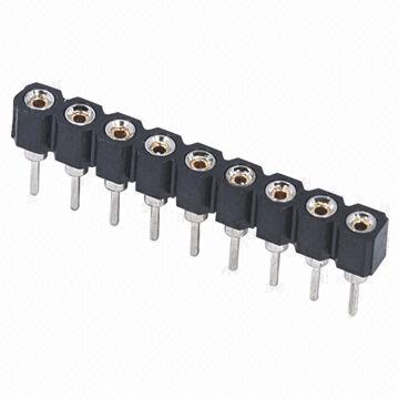
Hmmm I am not sure wether it will interfere or not.................You could probably use machine headers
Would be lot better..............
mystic ruin
Hmm maybe
I'll have to see if the attiny legs fit in ok
Good suggestion though!
I have some at home
onyx grove
Nice............
And the attiny alone is needed right................for programmming.................?
mystic ruin
Yeah this board is just for programming it
Once programmed it will be transfered to some other circuit/breadboard
onyx grove
Its a attiny programmer right.............?
mystic ruin
I built a shield to do this already but I just thought it would be a fun project
Yup
onyx grove
Hmmm...........So the goal is to program attiny..............
mystic ruin
Yes
mystic ruin
It sounds like you have more to add, Do you have any other suggestion? I don't mind criticism!
onyx grove
Yeah.
If I would have made I would have done it full smd as @lusty siren said addded a bit of LEDs...........and thats it
And if possible would have made it standalone.......
With a USB But thats a differnt subject
mystic ruin
I was going to use this to make it smd compatible
1pcs SOIC8 SOP8 to DIP8 EZ Programmer Adapter Socket Converter Module 150mil
http://s.aliexpress.com/nIrEvuii?fromSns=Copy to Clipboard
(from AliExpress Android)

I don't know of any other way to have removable smd programer
mystic ruin
I'm not too worried about it being stand alone, a bit over my head for my first project
The led and resistor are smd
mystic ruin
Cool!
onyx grove
😅 Cause I need to complete my typing lessons
 rotund hemlock
Just 3d printer a violin and I’m thinking about printing a clear one and put LEDs in it and a trinket that does signal analysis and lights up based on notes played...
onyx grove
Nice.........!
uncut meadow
Have an awesome project? I know you do! Show it today at 7:30 ET 4:30 PT.
Learn to get started: https://learn.adafruit.com/how-to-get-added-to-the-adafruit-google-plus-show-and-tell-circle/about-show-and-tell

Have an amazing project that you want to show to Adafruit? Here's how to get added to the Show and Tell Circle on Google+
😃
 proper tiger
Meditate here! https://bit.ly/MeditateWithRain
fair vessel
I have the solder sponge holder on thingiverse if anyone is interested in printing it: https://www.thingiverse.com/thing:2744439
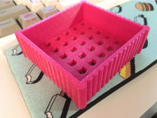
A soldering sponge holder with cat-shaped drain holes on the bottom.
Sized to fit the larger sponges sold at Adafruit.
karmic fjord
@fair vessel Nice print, but I'm confused by the drainage holes.
fair vessel
@karmic fjord so the sponge can dry between soldering. i'm also working on a dish for underneath
warped cobalt
So it doesn’t get moldy?
fair vessel
yes exactly
karmic fjord
Ah. Maybe it's the humidity level here (or lack thereof) but I never seem to have that problem. Mine is always dry when I turn on my iron. My routine is 1) turn on the iron, 2) go wet the sponge.
fair vessel
oh gotcha. yeah i usually have to let mine dry in a dish rack so i'm hoping this lets the sponge hangout with all the other soldering gear in between sessions
solar yew
I only wet half of a standard small kitchen sponge (yellow if I have one). I use the dry side to clean the tip of the iron with a small amount of extra abrasion. It's got scorch marks on it. Since I use the side of the sponge for this, I just keep it on an open coffee can filled with gravel (for ballast) which is my emergency 'make it stay put' desktop weight, as well.
May want to keep the poison out of the dish rack. < no manners, sorry.
fair vessel
oh good idea to get more of an edge. & no worries it's a good point
solar yew
I have plans to order one of those magnifier headset things that have a band around the forehead. Jerry's Art-o-Rama sells them (or did a while ago). More light and magnification helps me get a better solder joint. I make sure the joint is mechanically stable before I begin. Didn't used to. Joints look much better, this way. I also put a flashlight not much bigger than the AA battery that powers it (Cree, 90 lumens!) under my ball cap, so it's shining down my nose on the work, as a makeshift headlamp.
http://www.jerrysartarama.com/mag-eyes-hands-free-magnifier
fair vessel
that's awesome! more light definitely helps. i hanve't seen those headsets before. definitely sounds like they'd help with things
curious if i'd still need my glasses with that thing haha
solar yew
Probably not - astigmatism won't be corrected but it's often minor. You can rotate your head sideways to cancel a bit of that (as when viewing the Moon to get a slightly better look). Movie titles are the worst, in my experience.
 plain stream
huh, that looks cool
solar yew
I've seen those magnifiers in person -- they've carried them for two decades. Price is stable.
I want to add one more bit of resolution to this pushbutton DAC I built yesterday with the R2R ladder net.
https://github.com/wa1tnr/ADC-studies-arduino/tree/master/ADC_Gemma_M0_4bit/doc
Jcn R7, R8 and R9 is the output at present (location of V-out). Rest is unbuilt. I'm going to try doctoring the value for R1 to see where that puts me. I'll lower the value to bring the DAC output closer to Vss (ground).
Wow that really improved the spread - 47k in parallel with R1 (100k).
I dropped R1 to a singleton 18k. Improves the low end but the ADC is still reading about 640 ('units of ADC' for now until I look this upt). The next bit over will read higher than 640, but I did see 1000 as a reading when I let the ADC input pin float (disconnected from the resistor ladder DAC output).
solar yew
a0: 159-170   a1: 399-410   a2: 544-553   a3: 633-642
a0: 152-172   a1: 397-412   a2: 543-553   a3: 635-644  a4: 696-705
```Maybe the bits get squeezed downward when I add the next leg. ;) << nope@solar yew short discussion of such visors here: https://forums.adafruit.com/viewtopic.php?f=8&t=99556. I am in that thread.
keen temple
I assembled my Eweek arm, but some parts need to be redesigned for better range of motion.
lapis jasper
ordered pyoven baords from oshpark and posted the files here: https://github.com/chickadee-tech/pyoven

 sterile basin
@lapis jasper is that what I think it is? You’ll be able to automate your toaster oven?
lapis jasper
@sterile basin thats the goal, so I can use it for pcb reflow
sterile basin
Nice
One day I’ll need someone to explain to me what solder reflow is
I still have no clue
Like, no clue how ovens and soldering work
fair vessel
@sterile basin try this guide: https://learn.adafruit.com/adafruit-guide-excellent-soldering/common-problems?view=all

Solder at peak performance!
@lapis jasper that's really awesome! can't wait to see how it goes
junior agate
@sterile basin https://www.youtube.com/watch?v=_5lksMvmqQc < you can really see the process with SMT chips here, at hyperspeed!

We taught a SMT soldering class at the Atlanta hackerspace ( http://freesideatlanta.org ) focusing on using stencils and solder paste. Here are some shots of...
sterile basin
@fair vessel @junior agate thanks!
lapis jasper
thanks @fair vessel !
lusty siren
@keen temple Now you're armed!
And yes, I realize this joke is almost an entire day late
bitter hazel
@keen temple cool. You got more details about the build and cost? I’ve always wanted an extra helping arm in my life
rain escarp
@lusty siren He's just exercising his right to bear (robot) arms. I gotta give him a hand for that.
lusty siren
I'm not sure you need to give him a hand. He already has one extra
solar yew
I am trying to make a android os called "Star OS" were there are NO bloatware and it just looks diffrent
But the project is paused
night hare
@solar yew thats cool, would it be able to run normal apps or not?
 wanton mason
Red Star OS? :kappa:
solar yew
Yes, it would be able to run normal apps @foobar#4503
Maybe that should be a special edition of the OS. @wanton mason
Here is the reason why the project is paused, I looked at how to make a custom android rom and it does not support windows as I can see.
vernal ferry
@solar yew what was the thought behind variable line thickness on the logo?
solar yew
I went in a different direction with my ADABOX002: https://www.youtube.com/watch?v=JQBfuo-KPoM

Adafruit ADABOX002 Robot Friend modified into a BalanceBot using a MPU6050 sensor, Powerboost 1000, and a Feather Protoboard. A 3d printed frame (the red par...
 eternal maple
Nicely done, @solar yew !
solar yew
@vernal ferry I just wanted to add it like it is traveling in a fast rate
uncut meadow
Awesome!
woven relic
Woooshy woosh woosh!!!
uncut meadow
Awesome!
woven relic
Can I get a #sparky on this one?? I made my original set of motors spit out smoke, but it wasn't the magic blue smoke we all love. It was from the bearings over heating
uncut meadow
ask in the #adafruitextracredit
scenic siren
Show and Tell is the place to share Sparky moments 😃
uncut meadow
oh
woven relic
It's not really your typical sparky moment I guess
 coral spruce
We did a quick weekend project with some NeoPixels and a Trinket for our Lego Saturn V kit. We posted our process and the code for the Trinket in case someone else wants to make it! https://medium.com/@realasa/making-a-lego-saturn-v-blast-off-af5adc55d6f

Medium
For Christmas, my lovely wife gave me a Lego Saturn V. After building it and putting it on a shelf, I soon realized that I wanted a more…
fair vessel
@coral spruce that looks great!
coral spruce
@fair vessel Thanks!!
lusty siren
@coral spruce I agree with @fair vessel - Well done!
"We searched online and found a few open source projects for NeoPixels that had “fire” effects. After trying them out we decided to write our own library to get the exact look we had in our minds" Yep, you've definitely got the mind of a Maker.
coral spruce
Thanks @lusty siren ! We had a lot of fun dialing in the right amount of gradient vs. flicker. Here's the Github link if anyone is interested! https://github.com/asamiller/blast-off
 rain escarp
@coral spruce I look at that and wish I nabbed one of the Saturn V's when they were available last month 😃
lusty siren
@rain escarp Just build your own. You can even do full-scale!
rain escarp
But then I'd have to go to the moon. They don't have internet there!
lusty siren
You'd only have to visit.
rain escarp
No no no, if I'm going to go all the way there, I'm going to stay there.
lusty siren
Might need to build two, then.
rain escarp
At twice the price?
lusty siren
You'd need more than a few days' supplies
coral spruce
@rain escarp I think Toys R Us might have some online! Otherwise, I’m totally behind building a full, life-sized version. Lego will hold up to the stress of launch, right? 😂
 hallow hedge
hello evryone here are my reports for open source hardware held in Nigeria have a look at it and answer some of my quetsion https://drive.google.com/open?id=1lhtZcGSgoYD4E30RXzMX8BDxJ4AVQ0cY

Google Docs
plain stream
I know it's been said recently, but man does desoldering through-hole components (especially with a header) make you question your choices.
it turned out okay in the end though https://files.witches.town/media/media_attachments/files/000/918/338/original/c74f435b702b30a2.jpeg
 vernal ferry
@plain stream yeahhh, I have plenty of headers that i can sacrifice them -- lost some copper :<
plain stream
I pried it loose enough to get my snippers in there and then went to town
 clever pebble
when Ball Chair testing for the size and how it looks bigger before make a 3D printing files for it like those pillows
 marble tapir
Can't do the show and tell tonight, but here's my project for PAX South that I've been working on the past couple days instead of sleeping
Runs the same code as my tuba, but now with BLE control thanks to a 32u4 Bluefruit feather
It will be pinned to the back of my Enforcer shirt (that's the name of the con volunteers)
Initial plan was for a cape...but that's a LOT of lights, a LOT of sewing to secure them, and a LOT of power if I want them to last a day.
clever pebble
Small scale Ball chair
keen temple
@Miming#2270 I plan on sharing the finished design on Thingiverse, but I'm still testing the design. I'll post the link here, and mention your name, when it is available.
uncut meadow
Brodcast starting shortly. 5 mins left: https://www.youtube.com/watch?v=gIdVDJ3w5Vo&feature=youtu.be

Visit the Adafruit shop online - http://www.adafruit.com https://plus.google.com/+adafruit 1) Add +Adafruit Industries to your circles 2) Post a message/comm...
vernal ferry
Progress on my modified bag project.. Running on an ESP32 😃
running the I-C-U (I see you) animation from the WS2812FX lib
plain stream
Pinewood Derby car now has a rare earth magnet embedded in the back
I originally tried hot glueing the magnet on, but “force of rare earth magnet” vs “hot glue” was rather like Muhammad Ali vs me in a boxing match
lusty siren
I tried using superglue for a Rare Earth Magnet back when I did miniatures wargames.
That... only worked for a limited amount of time before ripping free.
uncut meadow
ik they are super strong
plain stream
it's superglued in now. seems to be holding well, but I really only need it for a small amount of time
lusty siren
Well, @plain stream - I was using two REMs pulling against each other, so that didn't help.
plain stream
ha, I suppose not!
lusty siren
There was also a gap between them
In retrospect, the whole design was awful, but... I was something like 15 and had never used them before.
vernal ferry
@plain stream yay superglue to the rescue!
bitter hazel
@plain stream what was the magnet for? Just for mounting the flora?
Also, cool derby car 👍 one of my first projects was frankenstiening a rpi 1 on top of an rc car but since I didn’t know how to rewire the motors to the pi I decided to just mount the remote on the car and wire the pi to the remote. It was a remote (ssh), remote (rc remote), remote car (rc). lol
plain stream
it's a CPX, but yeah it's for mounting
since there's only one it's a little finicky. and sometimes the wires jostle and I lose the I2C connection to the OLED. but it's a price I'm willing to pay to have no soldering/bulky alligator clips
solar yew
Haha.
I've done a great deal of improvising to avoid soldering. Lately I'm melting metals (did it for a living a very long time ago, so I do have the skills -- just don't especially like doing it).
I got to admit, the smell of it brought back good memories.
plain stream
I don't mind soldering, but it'd make my CPX not look shiny and nice
but isn't soldering also melting metal?
I mean, I appreciate the effort! 😄
solar yew
Soldering is melting metal. That's what I was referring to. /explains_Art
I remember that the part of the wire that had no solder wicked up into it, but was very close to the part of the wire that did have solder wicked into it .. that's the break point when a soldered wire (to, say, the edge of a circuit board) is bent too many times.
So I tend not to solder directly to something valuabe like an MCU target board, unless the thing I soldered to that target board cannot move, relative to the target, under ordinary uses.
plain stream
got it
solar yew
A good example of that was when I soldered wires to the graphic LCD ST7565 . I secured those wires more or less permanently, relative to the circuit board of the LCD. Since the wires I used (the Adafruit 6" jumpers) are nice and flexible, I'm not worried about the main length of them being bent, now and then, to fit around corners. I expect this soldering job to last me a good 5 years before one of the connections breaks.
 cedar dew
Hey guys. I have a project I'm working on that I can use a hand with. It's a 3D model of a modern take on the Assassins Creed blade. I'm struggling to print where I have a curved bottom sitting on top of a support generated by the out of the box Prusa software. http://bit.ly/2qYrZGZ. I'm thinking of just making it a flat bottom to print straight off the printer bed. I'd appreciate your help.

Here's my take on the Assassins Creed Modern blade. I'd appreciate if you guys can share some feedback before I do any further work on this. Don't forget to note work by the 3D designer from "Make It Real"
marble tapir
So I finished the project when I actually got to the convention. 😄


At PAX South this year I have a crowd controllable sign on my shirt. Hardware is @adafruit Feather 32u4 Bluefruit LE and Neopixels. Anyone using Chrome on Android can control it via a web page. https://t.co/uWEjaMf1KF
Twitter
So no one has to click through to read the whole thread if they don't want to, the shirt is using a Feather 32u4 Bluefruit LE and neopixels. It is broadcasting, via Eddystone, a url to a website. When people visit that website, if they are still close in proximity to be, it allows them to control the shirt.
It uses the new Chrome Bluetooth APIs to communicate, so it basically only works for Chrome on Android. However, for anyone with that combo, they can change the pattern, palette, and turn the glitter on and off.
solar yew
Mike Doell case mod - accept USB input for PiUART http://adafru.it/3589
Case mod == cutting an oval shaped hole in the case http://adafru.it/2251
Extech EX330 http://adafru.it/308 accepts the stacking banana plug of the Pomona Minigrabber Test Clip http://adafru.it/2607
mystic ruin
Hey all, I'm working on a video for my Zelda chest project and I would appreciate any feedback on what I have so far

My Tools & Kit*: Ts-100 Soldering Iron - UK : http://amzn.to/2nlOF23 - US : http://amzn.to/2jDcyxl Logitech C920 HD 1080p Pro webcam - UK: http://amzn.to/2pn...
(There is also some silence in the middle that I have since fixed)
Its only half finished as I need to do the electronics/arduino part
 urban gulch
Making a fume Extractor for my local makerspace(osmm) in RI. Soldering fume extractor, 3d printer case w/ logo and some helping hands 😄
plain stream
I need to get those fancy helping hands, I think. the ones I have aren't as flexible as I need
tepid adder
Haha! Success. Got a huzzah talking to the internet through wifi with circuitpython. May not seem like much, but I'm pleased. And now I can work on getting it to do something "real".
rain escarp
@plain stream I have the following Franken-helping hands creation. It's a wide heavy base with parts holders, an adafruit-supplied Hobby Creek brass ring with the actual helping hands, a low profile "base" so it doesn't get too tall [otherwise the loc-line hoses can't easily reach], and finally--- a panavise head of your choice. I like the JR head because it's small, cheap, and holds smaller circuit boards easily.
https://www.amazon.com/PanaVise-312-Tray-Base-Mount/dp/B000B63208/
https://www.adafruit.com/product/3019
https://www.amazon.com/PanaVise-305-Low-Profile-Base/dp/B0002BC1YU/
https://www.amazon.com/PanaVise-Vise-Head-Shaft-Bases/dp/B000SQWPY0/

We've really gotta HAND it to them, the Third Hand Pana Workstation brings the benefits of the Super Fancy Third Hand Kit to the PanaVise line of work holding vises. This is ...
plain stream
@tepid adder awesome!
rain escarp
Is it overkill? Yes. It's worth it though. It does everything I want, and it's extensible....I can easily swap out panavise heads depending on the project, and the loc-line hoses are a common part. I can add, remove, rearrange them as i see fit.
plain stream
nice! but jeez that's gonna add up quickly
strong phoenix
there's always discount Wednesday! aka AAE... 😛
rain escarp
Yeah, it's not cheap. That's the only drawback. It's one of my most used tools -- I already had a handful of panavise products sitting around, so I didn't need to get a lot for my build.
But for someone looking to upgrade from a $5 harbor fright unhelpful hands, it's a sticker shock.
plain stream
I have a bunch of adabox 10% codes too. and a gift certificate. so yeah, I'll be able to take a chunk off.
rain escarp
I personally don't recommend using the Panavise Jr Head + base. Because the head doesn't come off the base.

The best mini-vise for working on smaller PCBs (2.875" or less in one dimension)! The jaws are strong plastic that wont damage the PCB and doesn't mind if you hit it with the ...
I learned this the hard way...now I have a spare panavise sitting around!
plain stream
got it
rain escarp
I figure, spend the extra couple of dollars and get a normal base that can take any of the panavise heads -- if you want to upgrade with their monster circuit board holder, or larger project jaws...you have that option.
strong phoenix
i've thought about picking up a new 3rd hand setup. but, that would take out all the fun of "how am i going to solder this without burning my hand, or the house down?"...
rain escarp
Pffst, if you haven't burned at least 3 houses down by now, you're not even trying....
😉
strong phoenix
haha. fair point. runs to the neighbor's house with soldering iron in hand
rain escarp
"Marge! Remember our neighbor? HE'S BACK AGAIN"
plain stream
I own a house now and would prefer to not burn it down :p
rain escarp
I'm allergic to being burned alive. Gives me a nasty rash.
A few years ago during the summer, I was on a project designing rampage -- I was going to build a helping hands. And I sat down, looking at designs, drawing up things I needed in mine, sourcing parts, etc.
then, hobby creek came out with the brass ring. and I seriously smacked my forehead.....that's what I needed.
As antithetical it is to the maker movement, this is a project I felt it was best to just throw money at a solution.
solar yew
I just use bad words. For example (during meal preparation) when I take a hot roll out of the hot oven, instead of wearing oven mitts, I just use my fingers. At the moment of high-temperature contact with the roll, I say (rather forcefully) <bad word> that's hot!
I do the same thing in the workshop, when things don't (obediently) stay put while I'm working on them (between iterations of trying various immediate solutions to stabilizing them a bit more than they already are). When they move (again!) that's when the bad word is used.
So far, I haven't run out of bad words.
karmic fjord
I went for those arms and the large panvise. It's a bit of a monster, but is a joy to use.
mystic ruin
Let me tell you all about the wonders of blue tac
But seriously I do use blue tac all the time when I'm soldering
Its less than $2 for a pack here and its reusable
 ruby ledge
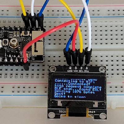
feedback wanted. I created a common API to access SPI/I2C/GPIO for ARM SBCs supported by the Armbian Linux project (it also supports Raspberry Pi boards). A new wrinkle to the idea is to have the same API usable on Windows/MacOS/x64-Linux by using an inexpensive Arduino as a remote I/O slave device. Here's an example. The left SSD1306 OLED display is driven by my Mac and the right one is driven by my Orange Pi Lite using the same C code (https://github.com/bitbank2/oled_example). Thoughts?

Both displays are running my https://github.com/bitbank2/oled_example project. The one on the left is running from my Mac remotely through an Arduino. The on...
lusty siren
@ruby ledge That looks super cool
I'm not sure I'd get a lot of use out of it, as my Orange Pi projects are almost entirely Android-based (H3Droid is really good for this)
ruby ledge
I just thought it would be nicer to test sensor/display code from my Mac rather than deal with the "sketch" world
lusty siren
Oh, yeah.
ruby ledge
either way, it just makes ArmbianIO project more useful
lusty siren
It's a great idea, I just don't personally have much immediate use for it.
ruby ledge
the reason I wrote it is because of the header pin situation.
each board maps their GPIO pins differently. I wanted to create a universal system where header pins could be referenced by the PIN number, not some odd GPIO numbering scheme
lusty siren
Makes sense
ruby ledge
even different Allwinner boards randomly choose different GPIO lines to bring out to the header
lusty siren
That sounds immensely annoying
ruby ledge
This allows me to run my test code on RPIs, OrangePis, NanoPis, BananaPis, without having to worry about the BCM/GPIO numbering
lusty siren
That's always great. Lets you make sure the bugs you see are actually bugs and not hardware shenanigans.
ruby ledge
right - and allows me to pop my LCD display onto any of my boards and my code works without having to change anything
SPI is SPI, etc
the non-RPI boards have tried to copy WiringPi, but don't properly support their efforts
lusty siren
That's one of the things I like about #circuitpython-dev - You can just use SPI_MISO for the MISO pin without worrying what pin number it is.
ruby ledge
I'm not a big python fan, but I understand the attraction
my mission is to learn the IoT world top to bottom and share what I can with the community
lusty siren
A good mission to have
ruby ledge
I don't look for "libraries" or "instructibles". I get the data sheet and connect it and write the code to drive it. Best way to learn. Then I share the results on my github
lusty siren
I dislike programming, so that sort of thing is completely the opposite of what I do.
ruby ledge
I'm almost at the point where I'm helping companies create useful products. The knowledge I've gained over the last 2 years has proved useful.
The Italian word of "conoscenza" better describes how I'm approaching IoT devices
anyway, glad it piqued your interest
lusty siren
...You used piqued (Correctly!) instead of peaked. And you're doing neat things.
You should also bring this stuff onto the weekly Show and Tell. I'm sure people would love it
ruby ledge
well - take a look at what I'm working on. It seems a little too nerdy/narrow-focus for this group:
https://github.com/bitbank2
 lusty siren
Nerdy and narrow-focus define a significant portion of the people here.
ruby ledge
ok, well - maybe you can suggest a topic from the stuff I'm working on that would seem most interesting to the group and I'll try to present it in a more friendly format
lusty siren
A lot of people use Raspberry Pis, and I've seen Orange/Banana/etc Pis used. And people would love to be able to control I2C/SPI/etc things more-or-less directly from their computer. That's something people would be interested in
ruby ledge
Ok let me make more progress, share the code, then I can talk about it.
lusty siren
Sounds good!
plain stream
@rain escarp whoops my finger slipped and I ordered all those panavise and third hand products
rain escarp
@karmic fjord @plain stream Awesome! [disclaimer: I'm not responsible if your wallet cries out for mercy]
plain stream
we're moving. I tacked it on to an order with a new tv and some mounting arms. no one will notice 🕵
rain escarp
hahaha, whatever keeps you from getting in hot water 😉
It adds up, but it's a buy-it-only-once sort of product
karmic fjord
Indeed. It was a incredible, and justifiable, upgrade from the basic/inexpensive things I was using. It does, however, look like massive overkill with it holding a trinket.
rain escarp
@karmic fjord What makes it nice is the ability to add many sets of hands. Here's a DIY kit from Sparkfun for making more "hands" with the loc-line air hoses [or you can source the hoses and parts yourself, if you feel as such]

This parts kit allows you to modify a coolant hose into an additional hand for your SparkFun Third Hand. It includes the alligator clips and hardware neces

These plastic Flexible Coolant Pipes have been primarily used to spray refrigeration or washing fluid for machine tools but, thanks to their articulation,
During one of Sparkfun's 20% off sales, I picked up a bunch of the hoses. Good supplier, I know they'd work with this application.
scenic siren
This is the one I got: https://www.quadhands.com/collections/for-your-panavise/products/quadhands-base
I love it
rain escarp
Versus going to Amazon and rolling the dice if the hose threading is exactly compatible...or even listed correctly 😉 😉
scenic siren
Panavise Jr in the center. And the arms are removable and I bought nuts and bolts to go with them, they're the same size as the standard Panavise hardware, so you could attach one to a different Panavise if you have mutliples.
And the customer service is amazing, which adds a lot to my opinion of products pretty quickly.
rain escarp
Never heard of Logo, they're solid?
*looks at their webpage -- woah, nice
If I wasn't already invested in a panavise ecosystem [long before i even assembled my helping hands I linked above], I probably would have seriously considered these -- they look nice
The magnetic base one looks sweet
scenic siren
Yeah you can buy more arms of different sizes separately if I remember correctly.
This was my first soldering accessory. I bought it through Amazon with a Panavise Jr. The base weighs a ton, it's incredibly solid. I've used it for all sorts of things and I've been really happy with it.
It's pricy, but I'm really glad I decided to get it.
rain escarp
i bookmarked it
karmic fjord
It's always a joy to upgrade to high quality products.
scenic siren
I never had one before! This was my first third hand and Panavise. Super exciting. Got it in June-ish.
karmic fjord
Nice
I had far cheaper versions for too long 😃 It was very much a case of dabbling and not being completely sure if I would carry on with the hardware work. it didn't take long to be sure 😃
But then it took longer to get frustrated enough with the cheap stuff to decide to upgrade.
scenic siren
I convinced myself that it would be worth it later even though I hadn't really done much of anything with soldering before. In this case, I turned out to be right.
Yeah I know that feeling.
karmic fjord
That was the first time I got all the freebies with an Adafruit order 😃
scenic siren
Nice! 😃
rain escarp
My journey with panavise started when I got a vintage circuit board holder vise + base from a yardsale for $10 (very much like this one)
https://www.amazon.com/PanaVise-315-Circuit-Board-Holder/dp/B000B5Y99C/
and then I got a few different heads. and a larger round base with little compartments for holding things, etc
[all the while, hating my Horror Fright/Harbor Freight helping hands -- you know, the tiny ones that everyone comes to disliike]
adafruit stocked the brass ring from Hobby Creek....and i was so impressed I stopped trying to build my own and just purchased it.
several years ago, at the time, there wasn't many options for helping hands that were well made + not out of line expensive. Feels like the industry has blossomed in the last few years with these tools. Which is awesome!
mystic ruin
An unsual show and tell, but I submitted a guest video for the EEVblog channel and it go picked!
https://www.youtube.com/watch?v=yabl87SD-3M

Brian is the one who wrote the ESP8266 Youtube library that I used in the Nixie Tube Sub Counter video series. Here he is showing you all sorts of cool libra...
karmic fjord
@rain escarp Oh wow... I remember those. They were standard equipment when I did my electronic tech program. I had completely forgotten about those.
vernal ferry
@mystic ruin AWEESOME!
mystic ruin
@vernal ferry yeah! I've been kind of a nervous wreck at 9pm every evening for the last week or so! He had emailed to say he was including it but he never gave a list of what days what would be shown so I didn't know if it had been forgotten about or what
mystic ruin
It seems to be being generally well recieved. It kind of insane to watch the views grow so fast on it, in 4 hours it has passed out my last 3 videos combined
solar yew
Looks to me like you more than earned your spot. @mystic ruin
mystic ruin
Thanks @solar yew !
@hallow hedge it will be on this time tomorrow
(or at least it usually is)
hallow hedge
Kkkkk
strong phoenix
?showtimes
 topaz leafBOT
3D Hangouts - 11am ET Wednesdays
Show & Tell (YT only) - 7:30pm ET Wednesdays
Ask an Engineer - 8pm ET Wednesdays
Desk of Ladyada - Random hacker times
John Park's Workshop - 4pm EST Thursdays
Desk of Tony D - Evenings PST Fridays
topaz leafBOT
3D Hangouts - 11am ET Wednesdays
Show & Tell (YT only) - 7:30pm ET Wednesdays
Ask an Engineer - 8pm ET Wednesdays
Desk of Ladyada - Random hacker times
John Park's Workshop - 4pm EST Thursdays
Desk of Tony D - Evenings PST Fridays
uncut meadow
?ShOwTiMeS
topaz leafBOT
3D Hangouts - 11am ET Wednesdays
Show & Tell (YT only) - 7:30pm ET Wednesdays
Ask an Engineer - 8pm ET Wednesdays
Desk of Ladyada - Random hacker times
John Park's Workshop - 4pm EST Thursdays
Desk of Tony D - Evenings PST Fridays
uncut meadow
?sHoWtImEs
topaz leafBOT
3D Hangouts - 11am ET Wednesdays
Show & Tell (YT only) - 7:30pm ET Wednesdays
Ask an Engineer - 8pm ET Wednesdays
Desk of Ladyada - Random hacker times
John Park's Workshop - 4pm EST Thursdays
Desk of Tony D - Evenings PST Fridays
uncut meadow
?ShOwTiMeSs
vernal ferry
Some quality air time with https://www.adafruit.com/product/3686 an esp32 and a tft featherwing. Also my first project with Adafruit IO, the tft featherwing displays streaming data directly from the sensor vs. adafruit IO's dashboard displays data over time.
Breathe easy, knowing that you can track and sense the quality of the air around you with the PM2.5 Air Quality Sensor with Breadboard Adapter particulate sensor. Mad Max & Furiosa ...
.. more graphs!
 quasi girder

Google Photos
 proper kraken
How bout dis for show and tell: https://photos.app.goo.gl/qPRokVbf4o5nVfe53

Google Photos
junior agate
@quasi girder 😮 it's a real-life soundboard
quasi girder
@junior agate it certainly is! As it's my first project, it still needs some work, but I'm pretty proud of it.
junior agate
I like it! uses the trellis?
quasi girder
Yep
The only issue I have is that the rubber button covers for the trellis don't always make good contact
solar yew
I'm giddy.
https://media1.tenor.com/images/782ba18e2ff1bb49a36ade1ab90f2869/tenor.gif?itemid=7549364

Sorry if that was inappropriate. I'm just so excited.
karmic fjord
@fair vessel I saw your "very bright" project. I have a couple dotstar projects so it will be a very, very bright show & tell tonight 😃
karmic fjord
I'm working on learning guides for them now.
cedar dew
Hey guys. Just showing off my take on the arc reactor. I’m using a modified version of the adafruit powerplant sketch for this one but I built this to get my feet wet using micro controllers.
karmic fjord
@cedar dew That looks amazing!
cedar dew
It still has a bit of work . You can see the Gemma board peaking out. The translucent PLA is great for diffusing light instead of clear plastic
Love what you're doing dastels. Wish I had a teach to show me real life tech when I was a kid. I think if you get them to build something practical or cool giving them options to add complexity, that would be great
karmic fjord
@cedar dew I thought I saw the gemma back there.
@cedar dew Yes, I'm looking into library based makerspaces (new book just came out) to see what I might be able to do here where I live.
@cedar dew I'm also seriously thinking about getting some proper audio/video setup and start streaming project stuff.
cedar dew
@karmic fjord If you need a hand with getting any 3D models done that you can print to help with this, I'd be happy to help
Free of course
karmic fjord
@cedar dew Ha... ya... My first 3d printer is scheduled to arrive early next month.
 formal kite
Whew. Made it - just got off a plane!
karmic fjord
someone remind me... where do I find the join the live stream link?
formal kite
@karmic fjord - Google Plus - give me a minutes I’ll try and find it.
karmic fjord
ok, I'm on the G+ page for tonight's show
 quick mortar
Hi all.
cedar dew
Hi
karmic fjord
got it
scenic siren
Can you link it @karmic fjord ?
quick mortar
And we're away!
mystic ruin
A video on my Zelda chest project if anyone is interested

Here is the chest from the Legend of Zelda games I made for my match on reddit secret santa. When you open the chest it lights up and plays the chest opening...
warped cobalt
Pretty sweet
 topaz dew
Real awesome. Cross-stitch Link is badass too!
mystic ruin
Thanks @warped cobalt !
@topaz dew yeah I thought it was so good! I'll let my wife know 😃
dense thunder
Hi everyone
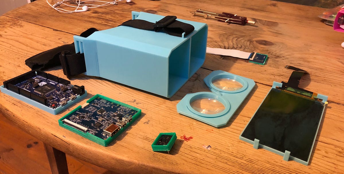
I created a VR headset from scratch for $100
freeCodeCamp
My name is Maxime Coutté. I’m 16 and I built my own VR headset with my best friends, Jonas Ceccon and Gabriel Combe. And it ended up…
mystic ruin
@dense thunder awesome project, I saw it on reddit this morning
dense thunder
thanks 😃 @mystic ruin
mystic ruin
Is this your first big project?
You are still in high school right? (or the French equivalent of high school)
solar yew
The other pi is just for scale. Got it working today. Had a scare. First boot was a bust. Finally found that the jumper between the pi and the hat was backwards. Anyway, I gotta cute little buzzer sound when I smiled in front of the camera about 8-10 times.
And a bright blue light 🤗
ruby ledge
@solar yew can you see if it's possible to run custom code on the Myriad2 ?
solar yew
I don't know theMyriad2.
ruby ledge
That's the DSP doing the work in your vision hat
They used to be hard to buy due to limited quantities and hardware/software delays. Now that Intel has bought them, they're more available and being used in more products
Movidius is the brand name
solar yew
Haven't gotten far enough. Just happy to have found I didn't fry a pi.
ruby ledge
it's a 12-core VLIW DSP that can do about 10x as much work as an ARM with the same amount of energy
I worked with them on various projects and would buy the vision kit if I could verify that the Myriad2 is accessible and able to be independently programmed
solar yew
Have you looked at the aiyprojects.withgoogle.com/vision site? There's quite a lot about "TensorFlow" (all Greek to me). Perhaps it might mean something to you.
ruby ledge
I'll take a look
solar yew
And there's a blurb towards the end about the 'mcu' and the gpio access to it.
solar yew
I thought tensor was a Roger Penrose word
His thesis in 1956, Tensor methods in algebraic geometry.
karmic fjord
@solar yew Tensorflow is google's deeplearning/neuralnet tech.
cedar dew
Hey Guys. Just showing off my finished power plant model - https://youtu.be/R-_Mn9t1OoE

This is my take on A model inspired by Iron Mans Fusion powercore. All 3D printed in PLA except the vertical supports which is ABS. I used a Gemma micro cont...
I know I added this here before but I got the lighting working properly. after fixing a few poorly soldered joints
bitter hazel
@dense thunder just wanted to give you and your friends props for that awesome vr headset! Keep up the good work you guys 😃
clever pebble
how many joules that generate?
cedar dew
1.21 Gigawatts per second
 neon island
is the way to share your project on show and tell still the google plus event thread? I dont think I saw one last wednsday
vernal ferry
Finally updated my esp8266 ledstrip controller ~ hopefully better & more stable than the previous version. Was a fun exercise in using different languages:

GitHub
Simple-LED-Strip-Controller - ESP8266 Based LED light strip controller via a web browser
karmic fjord
@vernal ferry Nice
Reminds me of one project I did... To start there was a World of Warcraft plugin written in Lua that kept track of where you were and displayed a QR code on the screen with that information. that QR code was read by an iPhone (camera watching the code on the screen) app witten in Swift that extracted the location when teh code changed, created json with the info and sent it via wifi to SteelSeries Engine written in Go which called a function written in Scheme (which I had written in Go as part of SS Engine) that took the location and got the color palette for that region (from data generated by a ruby script) and sent that color data over USB/serial to a teensy running code written in C++ that controlled an 8x30 array (8 strips) of neopixels. As you moved around in the world, the neopixels reflected the palette of the region, providing ambiant light to match where you were.
Whoa.. that's a sentence and a half.
vernal ferry
@karmic fjord sounds great! it's pretty cool how technology is malleable :}
karmic fjord
@vernal ferry It was fun.
lapis jasper
@neon island yup. I can try and get you the link later too
solar yew
Thank you, Alan Turing.
eager pine
This weekend I scanned myself with Kinect and 3D printed my own face 😊 Results were actually better than expected!
Could only print half at a time
woven relic
I don't think I shared my redone work desk!!
vernal ferry
@woven relic where all the magic happinz 😃
woven relic
Yup!!! loving my new rework station i just got! All i had was a small weller soldering station before
woven relic
lol nah i wish. those are blank usb plugs
 ocean cedar
Hi Everyone, just showing off some cases I made for the Raspberry Pi Zero. Made one out of copper and a few out of aluminum. CNC milled on a Taig and hand polished. Hope you like 'em!
woven relic
ohhhhhh very nice @ocean cedar
glad roost
@ocean cedar Beautiful!
ocean cedar
Thanks! Unfortunately, I made these right before the W came out, and putting anything with wireless in a solid metal case pretty much reduces the reception to zero! Oh well, I use these for my non-W pi Zeros.
vernal ferry
@ocean cedar slick :)!
ocean cedar
Thanks!
lusty siren
@ocean cedar Those look amazing. Too bad about the W, but they still look awesome.
ocean cedar
Thanks. Yea, wireless is great, but there are uses where it's not needed so that's what I've used these for. At some point, I may try to make one out of lack Delrin or maybe a nice hardwood for my W versions.
lusty siren
Can also just use an external dongle, too
ocean cedar
That's true, wireless or wired.
 harsh slate
@eager pine what software are you using with the Kinect?
karmic fjord
@ocean cedar Those cases are beautiful!
ocean cedar
Thanks, here's a video I took of the copper one just to show the polish and how it reflects. Still need to figure out a clear coating for the copper one. The aluminum ones hold the polish really well, but the copper one starts tarnishing in minutes if you touch it with bare hands!
 vernal ferry
@ocean cedar do you have other designs? :}
strong phoenix
@ocean cedar would paste wax work? A bit more tedious than say a spray-on, but that's usually what I do with my woodorking tools. Oh, and just remembered this one; check out BoeShield..

A multipurpose spray that provides superior corrosion protection, waterproof lubrication, and moisture displacement. Developed by the Boeing Company.
ocean cedar
@vernal ferry That's the only computer case I've made so far, but I've made a few toys from wood for my son on the mill:
@strong phoenix The polish I use has carnuba wax, or however it's spelled. It does help, but doesn't last long enough to be able to handle it frequently. Not a huge deal, as I just have it on a shelf. I recently watched a video on using a heat gun to melt powder coating and thought I'd look into clear and if there would be any issues with it sticking to copper.
There's also clear spray paint that's used often on classic cars and things like that. I'm just hesitant to try it since getting it back off if it doesn't go on well would be a huge pain!
strong phoenix
@ocean cedar yeah, carnuba would work too. just a no-no on in the woodworking world because of the silica (IIRC)...causes problems when applying a finish. RE: clearcoat...that's one good thing to Boeshield; easily removable.
eager pine
@harsh slate i used ReconstructMe http://reconstructme.net/
worked well! I thought the model would need cleaning up and removal of extra shapes (I used the free version) but when I opened the model in Cinema4D there was only one weird artifact way off in space I had to delete.
and i added some extra light by turning the flashlight on on my phone and taping it behind the kinect camera
clever pebble
@eager pine check this https://www.youtube.com/watch?v=oBO-0LC1nNM
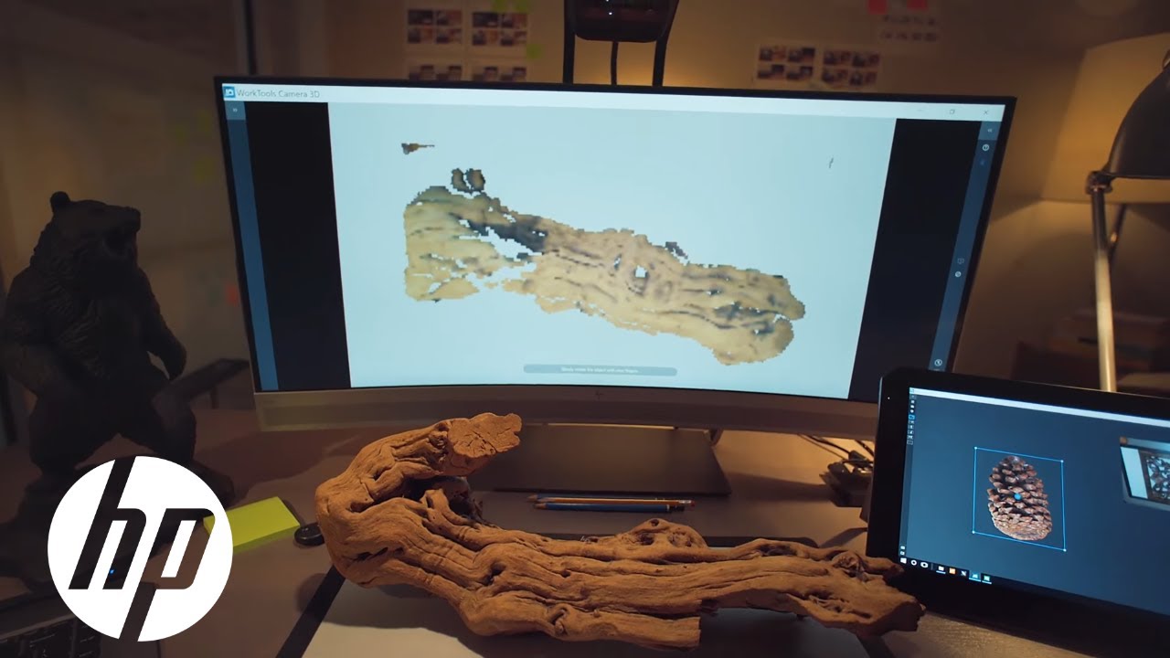
Reinvent creative workflows with the HP Z 3D Camera, which adds down-facing 3D and 2D capture to your display. Learn more: http://www.hp.com/go/z3dcamera SUB...
 regal dune
#sparky I decided that I didnt need pins and accidentally brigged the + and - pins without knowing, caught it before I tested it. Also got solder on pins that didnt need it. Also had to roll solder with an iron to barely get solder in it.
 obtuse walrus
Well, and explain a bit what happened :v
regal dune
Some of the solder that went through the board also hugged on to one of the chips
Because soldering upside down
ruby ledge
pro tip: use an iPad power adapter when testing situations like this. It has over-current protection and won't cause any magic smoke if shorted
I was testing someone else's prototype GBZ board and it had 5V shorted to GND
didn't cause any harm to the board or the power supply
 coarse fjord
Hi I am new. I made my first Arduino project this week a little device that consults the I-Ching for you (information on the I-Ching: https://h2g2.com/edited_entry/A647840 ) Here is a video on instagram of it doing its thing. https://www.instagram.com/p/BeWJ05Llcm9/

The 'I Ching' - the Book of Changes, from the edited h2g2, the Unconventional Guide to Life, the Universe and Everything

Instagram
7 Likes, 3 Comments - L. Christopher Bird (@zenmondo) on Instagram: “A working #arduino I-Ching using a 2.8" TFT Touch Shield from @adafruit Things are a little rough…”
bright hull
@coarse fjord neat. is it generating a hexagram?
coarse fjord
It is using the coin method
I found the image of an old chinese coin on wikimedia commons and used that for the bitmap of the coin.
I mean yes, it is generating a hexagram, using the coin method.
eager pine
@clever pebble oooh thanks for sharing that video about the hpz 3d camera - so cool!
solar yew
pots, switches
three per perfboard sector
File folder with document clamp - repurposed
The pasteboard offers good protection to the pins of the potentiometers during prototyping.
karmic fjord
Really hoping my PCB order arrives by Wed evening. That'll give me a reason to test my new cameras.
solar yew
It's nice to have something you really do want to show, instead of making up stuff to image for 'practice'.
karmic fjord
It'll be a nice followup/closure to the prototype I showed at the start of the month.
solar yew
Long day for me. Time for 'Rumpole of the Bailey' to unwind with. ;) seeya.
solar yew
Stacking headers on toggle switches. Crimp-on jumpers for the pot.
The potentiometer solder lugs are 2x4 cross-section shaped instead of 4x4 (post) shaped(**1) and so need some help with the female (Dupont) jumpers.
Crimping them, with the end of a Klein Tools 11046, does the job nicely.
____________________
(**1) lumber analogies ;)
Intent is to build an R2R resistor ladder net using potentiometers and toggle switches (to set the bits) for a digital to analog converter (DAC):
https://en.wikipedia.org/wiki/Resistor_ladder#Resistor_ladder_with_unequal_rungs
As a bonus, I should be able to build this logarithmic resistor ladder circuit as well:
https://en.wikipedia.org/wiki/Logarithmic_resistor_ladder#Circuit_implementation
The initial design is for a reconfigurable network (hence the effort to make things that can be unplugged and/or joined into some other part of the circuit).
vernal ferry
Working on my first project with a servo~ here it is in action:
https://www.instagram.com/p/Bej_WrVHHcx/
It's a small part of an enclosure that will live inside my bag. Planning to have a hole in my bag that will let some ambient air in for measuring temperature/air quality - I dont think this is the most rain proof or water sealed approach but should help a lil -

Instagram
7 Likes, 1 Comments - Timothy (@adaywithtimothy) on Instagram: “WIP. #opensesame #esp32 #espressif #adafruitfeather #adafruit #youvegotservod #servos #arduino…”
cedar dew
Here's an update of my "Apple of Eden" project that I'm making using a 3D print in clear PLA and white PLA, combining the halves of 2 different models. I have a trinket mini running 2 different sketches and LiPo battery powering everything through a power boost. I'm trying to configure a sense touch at the bottom to turn the power boost on and off through a transistor - I will assemble it all then gold foil everything except the lines.
Now that I’ve done enough with electronics, I’m finishing off my Apple of eden in white and translucent - I’ve combined the halves from the two models to sho...
eager pine
@cedar dew ooh that's gorgeous can't wait to see it with the gold foil!
cedar dew
ty @eager pine
eternal maple
Work in progress. One more Adafruit part to arrive (tomorrow, I hope?). Still need to insert a custom meter scale and attach the handle. I needed something to prevent USB prototypes from inadvertently loading my host tablet's USB power -- while still allowing me to send and receive data via USB, mostly for monitoring serial output and operating CPy's REPL. The meter was added so that I can watch the power load of the USB device under test. The overall design goal was to make it look like a retro HP benchtop power supply. 

... meter backlighting inspired by @terse totem 's workshop.
warped cobalt
I'm now waiting to see @terse totem wearing a basic black suit with that case, as he presents finale
strong phoenix
@eternal maple i envy your enclosure prowess. so clean.
eternal maple
Thanks @sommersoft#0222 ! It takes a while, but I enjoy taking my time.
woven relic
Does this count as show and tell?
Video from my couple of flights with my drone I built.
https://youtu.be/0m36na5pVug
 vernal ferry
@woven relic :O!!! awesome (also mighty blue sky 😉 puntended )
terse totem
@eternal maple that case and panel meter! So great.
eternal maple
Thanks @terse totem !
warped cobalt
@woven relic The local guilde is wanting to do drone flights at Cedar Rock park if you're interested
woven relic
@warped cobalt Is it a state park? If so we aren't allowed to fly there without a Ranger's permission
@vernal ferry thank you sir
warped cobalt
No, & it’s a group thing to get permission to fly in parks
vernal ferry
@woven relic 😃 Which MCU runs your drone/camera etc.. curious
woven relic
I have a Bardwell F4 Flight Controller. im not sure what MCU is on the board but i can look
@vernal ferry the MCU on the Flight Controller for it is a STM32F4 Arm Cortex
vernal ferry
ooooh googles it up
woven relic
yeah i had to google the board to make sure it was the MCU
vernal ferry
I've never flown a drone, is this an FPV one too?
woven relic
yup!
only reason that video looks so clean was because it was from my gopro that was attached to it. though i gotta get a better mount for it
vernal ferry
does it get... dizzying? or does the first person camera stabilised?
woven relic
oh theres no stabilization on the cam hahahaha its screwed down
 keen grove
is this strictly hardware based projects or can we do show and tell on like programming projects?
bright hull
@keen grove fine as long as it's generally makery or hackery related
keen grove
what's that mean?
bright hull
what's the project?
keen grove
just a game I wrote in python 3.4, I want to post a link to a gameplay video I recorded of it to ask how interesting it looks
one I wrote from scratch on my own
bright hull
@keen grove that's fine, go for it
keen grove
https://www.dropbox.com/s/wp1iosjd5y76mfh/2018-01-30-11-13-42.mp4?dl=1, 'eres a short gameplay video of a game I've been working on since late 2016

4,923 lines of code in all, plus 118,850 for the names of the stars, planets, species and ores
in all, about 900 kilotbytes of data uncompiled
woven relic
Whoop whoop!!!!!
 eager falcon
I built an exhibit for my local TEDx event with parts from Adafruit. The show was Saturday and it went great. Here is a short clip.
https://youtu.be/IeXUfnC5DCs

 sudden notch
`
solar yew
Seattle .. did MS-DOS and shipped a chip with it.
 grave wedge
@solar yew my understanding was that Seattle Computer Products build an
8086 S100 board and that the DOS came with that board.
I forgot to mention you can find out more about IRLib2 all my technology blog at http://tech.cyborg5.com/
I also forgot to mention that I wished I had a photo of power supply and that old 1970s era S100 based computer. It was a non-switching power supply with a transformer that was about a 5 inch cube and it had capacitors the size of a frozen concentrated orange juice can. The thing was a monster.
The 16k memory boards consisted of 1k by 4 bits ICs with a total of 32 of them on each board. The entire thing ran at 4 MHz. There's almost more computing power in an Arduino Uno then there was in that behemoth machine from 1978.
ruby ledge
reminds me of my early computing days
my friend had a CP/M-85 running at 4Mhz and we thought it was incredible
my first machine was a TRS-80 Color with 4K of RAM running at 0.895Mhz
keen grove
and nowadays anything less than 2ghz is crap
and anything with less than 2gb of ram is crap
and 512 mb of vram
 tidal citrus
I remember when I did my first build on my own and 1ghz was really fast and now my 4.2 seems slow sometimes
coarse fjord
My first computer used a 6502 running at 1Mhz
keen grove
my first computer had a #700 mhz 32bit arm apu
tidal citrus
im not sure the specs on my first, I was only refrencing the first one i built on my own
it was an apple 2e I think
coarse fjord
That computer with the 1Mhz processor was an Apple II + circa 1978 or so. Then I used a lot of PCs back in the day that were 4.77 MHz I think. I think that was the standard clock speed for those 8086 dealy-jobs. When my school got a 16Mhz 286 we thought it was so fast the letters came on the screen before you typed them. It was also the first processor we saw with a heatsink, we thought they were doing something wrong to warrant that
coarse fjord
the 286 computer came free with the purchase of the CD-ROM drive and a subscription to an Encyclopedia on CD-ROM
So to be clear the CD-ROM drive was the expensive bit, so much so that they threw in a free computer when you bought the drive.
tidal citrus
and the the time i put a stick of ram in wrong .... thats the day i got my magic blue smoke badge
coarse fjord
When I was in school, studying electronics, there was a lab project that the circuit was designed to burn up a resistor and let out the smoke. To kind of drill into us the kind of situations that would do that.
tidal citrus
to my discredit it was a cheep mobo with no little platic think to block that sorta thing
never happed again... at least so far
coarse fjord
I don't recall but I seem to think I blew up an IC of somekind during my time at Intel, but the memory is hazy.
tidal citrus
And thats why this project I am about to order terrifies me, I have never realy solderd more the a bunch of leds (and resisters) building a pc is easy not cooking sometothing from miswiring not so much
 sudden sable
Syringe Pump Assembly
stable kayak
Looks awesome.
sudden sable
Bearings, Threaded Insert, Coupler, Motor, Carriage, Frame, Saddles
Controller
For slow steady fluid circulation in lab's cochlear tissue experiments.
sudden sable
60 ml
stable kayak
What are you making?
sudden sable
@stable kayak Part of an fixture that holds a tissue sample. The syringes will push and draw artificial inner ear fluids beneath the sample to maintain consistent composition over the course of experiment.
stable kayak
So a biomaterial printer, kind of?
sudden sable
Biofluid wash, more like.
tidal citrus
Better then a mag spinner I take it?
stable kayak
Sounds nice.
sudden sable
Mag spinner, unfamiliar to me.
sudden sable
Ah, for us yes - we stimulant the tissue samples with sound or current to measure how it moves in response. Stirring or a noisier pump like peristaltic would add noise.
tidal citrus
U have also contemplated using them in my dye work
sudden sable
*stimulate
Hoping to upgrade soon with control through USART and OLED - that's what the empty headers on the board are for. Currently operation is manual, just the LEDs for indicators of which motors are active, flow direction.
tidal citrus
And the tiny tissue + noise would be bad
sudden sable
The tissue is bananas fragile. Other lab members tried peristaltic and destroyed there samples with the pressure.
*their
tidal citrus
Wow
stable kayak
Sounds crazy.
sudden sable
A few millimeters of water's worth of hydrostatic pressure can do similar damage. We've been trying gravity driven flow but it's difficult to keep steady for long durations. This should give us at least 30 minutes between refills of steady circulation.
Excitement related, the while loop of the controller's main is empty - just ISR's.
tidal citrus
How long are the experiments? I take it not long with 30 min being good? Sorry this is a topic of interest to me as I am hearing impaired, I like seeing advances in the field
stable kayak
Oh my
sudden sable
We work with very recently excised tissue samples, from preparation to end of experiment the sample is in our hands for maybe 2-3 hours, with preparation taking about 1 hour. After that, the cells in the sample that respond to electrical stimulus are mostly dead. Hopefully the improved composition control from this device extends that duration.
stable kayak
Sounds like an interesting project.
sudden sable
In experiments where the stimulus is mechanical only, that might extend to 5-6 hours.
That 1 hour preparation time is spent working on a fragile bit of bone and tissue about 2mm in diameter. No coffee allowed before dissection.
stable kayak
I can imagine why coffee wouldn't be allowed.
tidal citrus
One of the smallest bones in the body I think?
stable kayak
Correct.
sudden sable
Not sure of the size in humans, we use gerbils. Unmodified, cochlea is maybe 2.5mm diameter, 3mm tall.
stable kayak
Oh my
sudden sable
To close. Appreciation to Rochester Makerspace - laser cutter for frame, printers for syringe mounts and carriage and lathe/mill for couplers were very handy.
stable kayak
Awesome.
tidal citrus
As in Rochester NY?
ruby ledge
or MN?
sudden sable
Aye, snow home.
tidal citrus
I'm from there
ruby ledge
cochlea in humans is quite a bit bigger
tidal citrus
I'm in Albany now
tidal citrus
So if this works well, will you move to a larger syringe?
sudden sable
Not sure, may get cumbersome. I would more likely add another pair of syringes so one set can circulate while the other refills/empties.
Max flow rate is pretty limited by the gear reduction of the motors and low pitch of the thread, which is good for making flow steady but will likely make refilling a little lengthy, so not having to interrupt circulation during refill is preferred.
 plucky otter
This is how you do image capture right?
stable kayak
Looks great.
 red cobalt
There's no school like the old school. I remember seeing old cast-metal monsters that clamp onto the front and give you a little periscope to peer through as you operated your film camera below…
lusty siren
I love the clicky switches and buttons and want to make something with them, but I have no idea what
tidal citrus
I have an undying love of cherry mx blues, why not make a hot key pad of some sort ?
lusty siren
I don't even use the one built into my keyboard....
Also, was more thinking the toggle switches/buttons like are on Adam's SEM control.
tidal citrus
heem I am way caught up in my project atm but if something comes to me i will let you know
 indigo charm
Finally finished my first project in a while! HomeKit enabled NeoPixel strips: http://www.fischco.org/technica/2018/diy-homekit-lights/
BlinkenLights!
We recently took the plunge and got a bunch of HomeKit enabled light switches for our house. After that we got a string of the Hue Lightstrips for pretty multi-colored lights! After looking at the Hue strip, I thought that would be a cool project to build your own version. It also gave me an excuse to play with some NeoPixels which I’ve wanted to play with for a while now. :)

DIY Lightstrips with NeoPixels, FadeCandy, and a Raspberry Pi.
grave wedge
IRLib 2 update released. Fix problems with Trinket M0 unable to use pin 3 and pin 4. Hats off to @marsh quest who found the problem. I defy you to name another electronics CEO who takes the time to debug someone else's library. Here is the link on GtHub https://github.com/cyborg5/IRLib2

GitHub
IRLib2 - Library for receiving, decoding, and sending infrared signals using Arduino
eternal maple
To make it easier to learn and prototype with CircuitPython when traveling, in a waiting room, or at the makerspace, I picked up one of the purple zipper cases (https://www.adafruit.com/product/3704) and made a CircuitPython to-go kit. Now I just need to sew on a Blinka patch to top it off.
The case is just the right size for a FeatherWing 2.4" TFT display. I have a black one that may be altered to include a clear polycarb window for the 2nd gen corrosion monitor remote. The case's substrate is formed flexible foam, similar to foamed PVC, with a layer of fabric on the inside and outside. The outside is a coated synthetic fabric that is heat-sensitive. Sewing or E6000 may be the best way to attach parts and patches to the case.
rain escarp
@eternal maple Weird question about the case -- does it have a chemical smell? Sometimes cases like that have a pronounced plastic/chemical smell that's offputting...
eternal maple
@rain escarp It's very slight. I have a very sensitive nose and didn't notice it until my sensor was within about an inch.
rain escarp
That's seems managable.
I've had camera tripods stink -- the plastic on the rubber feet was sticky, and was actively offgassing for a week after delivery. Needless to say, it was double-bagged and returned promptly.
 plush gorge
I first came on show and tell to talk about this project over a year ago, my Dalek. Lol well Dalek to be. Unfortunately it afford a major set back. I've been having issues of one sort or another sense about a month after I showed it on show and tell, well kind of fried the main board circuit board while trying to test it after installing a new part. 😦 R.I.P. Dalek.
That is until...
As we All know Daleks will always find a way to return. 😉
solar yew
C8051F330D driving 14-segment LED display module. CP2104 'PiUART' repurposed to talk to the 8051 chip.
Upper left: Vcc 3.3V monitor (green LED) and a pushbutton RESET circuit for F330. Also, an NPN transistor 2N2222A to invert one input of a Darlington transistor array.
CP2104 PiUART top center. ULN2804A Darlington array in upper right (to sink common cathode LED array.
Silabs C8051F330D microcontroller (lower right) is sourcing 3.3VDC to the LEDs (all of them, simultaneously, via 470 ohm current-limiting resistor bank in lower middle right).
solar yew
C8051F330D lower left configured for JTAG/C2 (F330 uses only C2) for debugging or reprogramming F330 without the (serial) bootloader (which operates through MAX3232 serial interface, or (as shown here) Silabs CP2104 USB-to-UART bridge (PiUART)).
A pair of transistors (biased for an earlier project) remain in lower center (NPN on the left feeding PNP on the right). The remainder of the /RST circuit (1N4148, 1k resistor) for F330 is hidden under the mess of wires needed to make 14 segments lit (RESET is at row 50, column a, nearest breadboard).
There are also ten 0.1 uF disc ceramic (in parallel) to substitute for the 1 uF callout for a capacitor that's also in the RESET circuit; they are (also) hidden under the ratsnest, and occupy one set of power rails.
solar yew
The original values were 47k on the input of 2222A, and a voltage divider of 2k (1k, jcn, 1k) up to Vcc for the output from 2N2222A. That was no good; so the new output is 470 ohms on the low end and 2200 ohms on the high end, lowering the output so that ULN2804 is turned off entirely (2804 was leaking current, because it was not turned off hard enough with the 1k/1k divider output).
ULN2804A is turned on by bringing its input up to Vcc (I'm using 3.3 VDC, throughout). It is also an NPN transistor, and in a sense it is an inverter (it operates by sinking current to ground on its output, for a positive (logic HIGH) input). 2N2222A operates similarly, and needs a postive voltage (a logic HIGH) to conduct.
The active 2N2222A circuit is just below the RESET button, and feeds the singleton input to ULN2804A (upper right) to control one of the multiple, 14-segment alphanumeric display digits. 2804 turns all 14 segments on or off, by sinking cathode current of the LED array, originating with the microcontroller, C8051F330D).
The plan was to select digits for refresh in this way, but there were no pins remaining on F330 -- this is an unresolved problem. In the interim, it was found that joining the inputs of a pair of adjacent Darlingtons was sufficient to switch on both outputs, even while keeping those separate.
To keep from burning up the F330, a time slicing is specified in the program so that only a single LED is lit at any one instant. This iterates faster than the eye notices easily (uncalculated at present time) with a very wide video blanking pulse (nothing lit) punctuating each transition. The 470 ohm current limiters are at near the limit of the microcontroller's carrying capacity.
The program is carefully configured so that any power-on reset type of state it might enter tends to turn off the LEDs -- it's fairly difficult to illuminate even one LED by mistake. So there's a bit of failsafe built into the program (and maybe the circuit as well).
ULN2804 was available, but no driver transistors (PNP) for the individual LED segments were on hand, save the one.
Though I believe the F330 is good for about 8.5 mA per GPIO pin, and was better in one mode than the other (push-pull vs open drain) 8.5 mA was chosen as the max for a port pin on F330, which prompted the 470 ohm current limiter.
Port I/O DC Electrical Characteristics.
Output High Voltage I_OH = -10 mA, Port I/O push-pull Vdd - 0.8 Unit: Volt
Output Low Voltage I_OL = 8.5 mA  Max 0.6 Unit: Volt
I_OL = 25 mA Typical: 1.0 Unit: Volt
Low: 25 mA; High: -10 mA.
Tells me it can sink 2.5 times the current it can source, and when it is sourcing current it must be configured as push-pull. When sinking, open drain (PnMDOUT bit set to zero).
I think I decided they made one coefficient negative to indicate the same system of reference to both measurements.
Smoke test was just fine and I suspect I could get a lot more 'currenty' with this micro, but I'd rather time-slice it and use a thin duty cycle -- the voltage regulator and the micro run at temperatures that don't alert the fingertip (standard thermometer) so I think things are good there, but I'd like some numbers to work with (not sure how reliable an ammeter might be inline with Vcc, with a pulsed load).
eternal maple
Since I'm upcycling five holiday window decorations with NeoPixel strips (instead of incandescent rope lights), a PCB will speed up the assembly process and will likely make the end result more reliable and maintainable. Besides, I love PCB layout -- that's probably the main reason for making a PCB for a relatively simple circuit.
solar yew
Love the silkscreen ❤
 shut mesa
This is a bit old, I made it a few years back.
T-Rex using raspberry pi A+ and blatantly ripping off the excellent Beetbox project.
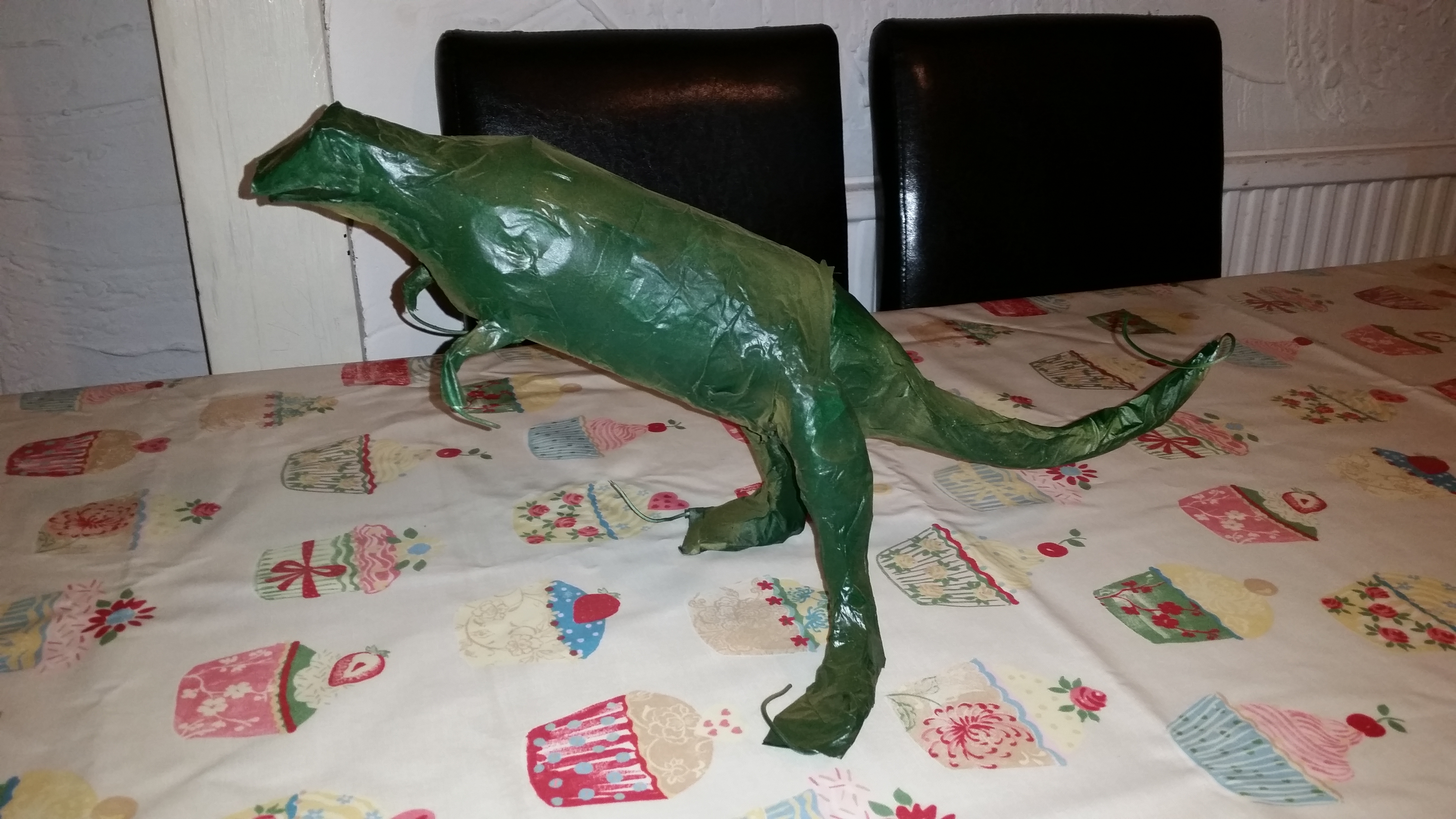
@tidal citrus I jumped in a time machine and wrote up that blog post 3 years ago, just to fulfil your request.
tidal citrus
that thing is sweet
shut mesa
There are better options for the electronics really, one of the audio fx boards would be much more efficient.
tidal citrus
but you had fun
shut mesa
Yeah, and I had an A+ to hand.
Like I have about 6 pi0W's to hand
And 4 pi3's. And.... well lots of parts lying around.
tidal citrus
wow
shut mesa
I'm planning on having a robot building day with my kids and a friend's kids, so I got a bunch of 0's for it.
tidal citrus
nice
 coral gull
Hi, I'm going to try finishing this project either tonight or tomorrow, as I'd like to showcase it on Show and Tell
scenic siren
@coral gull The link is usually posted into #live-broadcast-chat when Show and Tell starts. Look for that tomorrow!
coral gull
I will, thank you!
already got it half done. Installed the 2 voltage regulator boards, transformers and switches. one board is a boost/buck I set to keep the tube filaments at 12v, the other is a boost board set to 115v to power the tubes' plates.
I'll sleep now and finish it when I wake up, it's almost 4:30AM (thank goodness I'm only working thursday and friday this week!)
solar yew
hehe dino no touchy me! Love it 😃
shut mesa
Thanks TreeHouseCookie.
As soon as I saw the Beetbox I knew that I wanted to make it, but an exact duplicate wasn't for me.
solar yew
That's a nice healthy B+ supply. ;) What tubes are you running and what are their functions?
mystic ruin
I made my wife a present using el wire and a photo frame
It was a nice quick enough project, the el inverter is very loud though
lusty siren
Looks like you've got a bit extra in teh back, too!
keen grove
why not just give her a nokia 3310?
because nokias are indestructible
so it can be a symbol of your love to her, and it can also allow her to play a vintage copy of snake.
solar yew
I think nothing says love like a Lockheed SR-71 Blackbird, but that's just me.
lusty siren
@solar yew I know at least one person that would agree with you
strong phoenix
<-- this guy? still my favorite aircraft. A-10 is a close second.
warped cobalt
Only indestructible phone I liked was G-Zone Commando
keen grove
the only way to destroy a nokia 3310 is to take it to mordor
warped cobalt
Win my heart with a P-40
keen grove
the one ring was made of nokia 3310s
warped cobalt
G-Zone Commando only can be destroyed by explosion, TNT isn’t enough
strong phoenix
my nokia N70 was very tank-like as well. but yeah, the 3310 was the king of tanks.
warped cobalt
And I surfed webs & stuffs on it
And I know it’s indestructible, because it survived worste of construction sites
keen grove
the nokia 3310 physically cannot be destroyed
stable kayak
You drop it and the earth implodes. And THEN explodes, because that's totally how explosions work.
warped cobalt
I’m sure I can
stable kayak
Try putting it through a mallet.
warped cobalt
Let me use it on construction site
If it survives, I’ll give it some kudos, if it can stream anime after it, I’ll like it
If it can stream anime on 4.5” screen ( or bigger), I’ll consider it
stable kayak
The new one probably can.
keen grove
my laptop is so big and clunky yet sturdy, I could beat nosy people who nosily stare at my screen with the computer and it not break
my laptop is weaponizable
warped cobalt
You never dropped electronic device down elevator shaft, have ya?
Oh, say 7 flights
stable kayak
Wheras my laptop would implode out of existance if it got poked.
keen grove
my laptop probably would too if it had an ssd
stable kayak
My laptop is apparently waterproof. It is NOT impact proof, though.
warped cobalt
I put in SSD/HDD hybrid
Battery died
Which is why it quit working
Ugh, it only lasted 11 years
coral gull
I finished my project and it works as it should! I'm very happy with it https://www.youtube.com/watch?v=B79d7bydqr0

Mini amp using 5902 and 6N21B Subminiature tubes
warped cobalt
Awesome
solar yew
nice work!
vernal ferry
a prototype adafruit io connected air quality monitor using the following: https://www.adafruit.com/product/3315 ,
https://www.adafruit.com/product/3405 ,
https://www.adafruit.com/product/3686
on the next prototype ill be adding a ccs8111 inside somewhere as well. I'll show how the interface looks like when i've gotten more work in it.. so far it generates a line graph for visualising air quality over time. Used my soldering iron to test out the sensor.
also trying out taking photos with the glossy side of a vinyl sheet as background, I am still playing around with the lighting & I need to find a good tethering workflow with my camera -- Lightroom CC Classic 's tether feature is very buggy.

A Feather board without ambition is a Feather board without FeatherWings! Spice up your Feather project with a beautiful 2.4" touchscreen display shield with built in microSD card ...

Aww yeah, it's the Feather you have been waiting for! The HUZZAH32 is our ESP32-based Feather, made with the official WROOM32 module. We packed everything you love about Feathers: built ...
Breathe easy, knowing that you can track and sense the quality of the air around you with the PM2.5 Air Quality Sensor with Breadboard Adapter particulate sensor. Mad Max & Furiosa ...
:p also one of these days ill show up on show and tell live --
keen grove
yes
pringlebot 9000, circuit playground edition
now in sour cream for a limited time only!
 leaden frost
How many chips in the can?
keen grove
9000
the more you put in it the longer the battery life
because potatos are a power source
vital plank
Step 1: Eat pringles (sorry, I didn't keep count)
keen grove
if I eat enough potatoes, will the amount of bioelectricity I generate increase?
solar yew
All Your Pringle Are Belong To Us
keen grove
maybe I should eat lots of potatoes so I can charge my laptop when I'm away from a wall outlet
leaden frost
Newton's law - it takes a lot of energy to move a couch potato.
vital plank

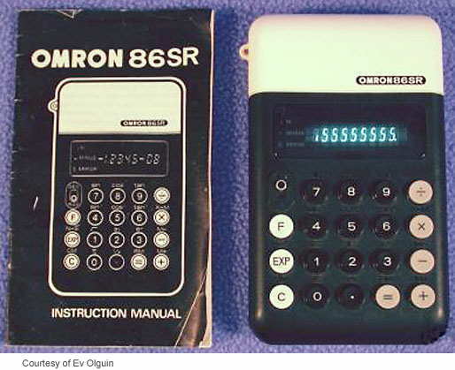




 junior dust
exploding button!
leaden frost
@junior dust Nice animation. Too bad that the same mechanism is used for anti-personnel mines. Remember to use your powers for good and not for evil.
 hearty basalt
Hello this is my first time on show and tell channel
I made a pcb that interfaces the ESP32 dev board with Buttons and a 2.2inch LCD screen
the cad
The button silk screen promoting Falcon heavy launch
PCB from Fab front and back
The "hacks" for horizontally misaligned pads
The final working version with a NES emulation
The actual soldered ESP board (top vertical) and a generic ESP32 board (for comparison, bottom horizontal)
lapis jasper
@hearty basalt awesome silkscreen
proper tiger
Anyone know where the link to sign up for show and tell today can be found?
indigo charm
^^ me too!
coral gull
I think they'll post it when they go live? it's what I was told at least
eternal maple

Have an amazing project that you want to show to Adafruit? Here's how to get added to the Show and Tell Circle on Google+
lapis jasper
@indigo charm @coral gull @proper tiger I usually have it early and can post here if you ask me for it
indigo charm
Cool, I'll try and msg you early next week. Finished a write up of DIY HomeKit enabled neopixel strings I'd like to share: http://www.fischco.org/technica/2018/diy-homekit-lights/

BlinkenLights!
We recently took the plunge and got a bunch of HomeKit enabled light switches for our house. After that we got a string of the Hue Lightstrips for pretty multi-colored lights! After looking at the Hue strip, I thought that would be a cool project to build your own version. It also gave me an excuse to play with some NeoPixels which I’ve wanted to play with for a while now. :)
scenic siren
@buoyant breach That's amazing!
buoyant breach
@scenic siren Thanks!
cedar dew
Hey guys. Showing off the final model of my Warded man display. This piece is based on a Book series by Peter Brett called the Demon Cycle. The base is 3D printed from translucent PLA then finished with Gold leaf and distressed. The hand is slush coated with epoxy resin then covered with bronze coat. The lights are driven by trinket micro-controller attached to a power supply and some neopixels. https://youtu.be/I7D1SXl-hGM

This is the final result of my Warded Man hand Avatar display.
tidal citrus
@buoyant breach how long till you can test the neopixels ?
buoyant breach
@tidal citrus I have to wait for it to fully dry so probably not until tomorrow night at the earliest
tidal citrus
I can't wait to see it
 fast shoal
I can't either జ్ఞా
tidal citrus
I used to make paper when I was in middle school, I am sad that i did not keep it up
fast shoal
Sounds fun
buoyant breach
I'm taking a paper making class in college this semester but I thought I could mix in some electronics too
tidal citrus
I saw on the cast, i thought it was very cool
I would love to know about the presses you have accsess to some time
buoyant breach
Sure! I will be sharing more next week once I have my neopixel paper up and running
tidal citrus
cool
 fiery lark
bright hull
fiery lark
bright hull
@fiery lark nice. hey, is that a reflow toaster? 😃
plain stream
gotta have your toaster streudels while you game!
(but really, that's awesome. I'd like to build an arcade cabinet soon, particularly because I have two joysticks and four buttons already)
oh, great: I just saw that the adafruit joysticks I have use sanwa balltops, so I can swap out the red on my second one and have different colored buttons for P1/P2
mystic ruin
I recently got into the high end reflow oven game myself
lusty siren
I had a toaster oven once, years ago.
I managed to set it on fire by cooking bacon in it... without a tray.
The bacon was fine. Heating up the apple pie later was not. Woosh!
mystic ruin
"The bacon was fine. " phew, thats the main thing 😃
lusty siren
The apple pie was fine, too!
mystic ruin
even better!
lusty siren
It wasn't a big fire, but boy was it surprising.