#show-and-tell
1 messages · Page 5 of 1
 molten jewel
 exotic sierra
molten jewel
is that the 1.3" screen?
exotic sierra
molten jewel
is that the 1.3" screen?
Yup
 reef flax
Hi all, just wanted to share my case I created for the Pimoroni Hyper Pixel. 🙂 Prints in one go no supports needed. https://www.tinkercad.com/things/7ZqPsQFhYTl-hyperpixelcase

Tinkercad
3D design HyperPixelCase created by 3D Hippy with Tinkercad
 exotic sierra
working on cleaning up some old designs. This is the RPGA Feather, a Feather with an RP2040 and an Lattice iCE40 FPGA.

The cleanup comes as I'm working to get designs from EAGLE to KiCAD. So far, so good.
molten jewel
oooh purty

 north mural
That looks amazing.
 timber peak
Meet the Picuno (Pico+Uno) powered by the RP2040 with level shifting to 5V on select GPIO for almost complete backwards compatibility with the Arduino UNO. Also similar to the metro. Just thal all GPIO are mappaed out to headers and level shifting to 5V from 3.3 to vice versa has been added. Fully open-source as well. Specs: atrivatech.com/picuno and File Repo: github.com/atulravi/picuno

 quartz needle
Progress! Now to figure out switches in Circut Python
 weary night
Hi everyone, I wanted to share with you a project that I have been working on for about a year now. I had created several projects based on the former PyCOM GPy. The PyCom company unfortunately made these modules EOL way to early and a few months later they bankrupted. This left me with some projects for which I had no good modules. I failed to find a good alternative and took on the challenge to create a pin compatible successor to the GPy. The work is now finished and I created Walter, a fully open source cellular IoT module with LTE-M, NB-IoT, GNSS, WiFi and BLE. In contrast to PyCOM all software is open source and available on github. At the time of writing the laboratory is finishing the CE, UKCA, FCC, IC and RCM certifications. I have tested Walter all over the world with the help of beta testers (https://walterdemo.quickspot.io/) and it is stable as a rock. If you are interested I would love for you to have a look at my project on Crowd Supply https://www.crowdsupply.com/dptechnics/walter

Crowd Supply
A certified ESP32-S3 module with LTE-M, NB-IoT, and GNSS for prototyping and production
 sonic fractal
I made a small wifi weather station with my DX32 and a BME280 (by mashing code the frankenstein way) it also has an oled that displays the IP adress, temperature and humidity

It uses the adafruit sensor libraries, u8g2 and WiFiManager (goated library)
sonic fractal

i put it on the freezer

pretty brutal endurance test
i also added a button to wake up the oled from sleep, this saves power
 willow loom
 north mural
is that your own board or something you purchased? it's fixable with flux.

 low pulsar
 dark cairn
ch340dip
dark cairn
ch340dip
@dark cairn nice! I've never dared to try it, but just trying to learn from your attempt - a) is that magnet wire, or something else? b) did you start with soldering on the legs on the chip first, or on the protoboard? c) Guessing you may have tried it both ways - is this easier/simpler than putting the chip upside down (dead-bug style?)
dark cairn
low pulsar
<@614096041083404300> nice! I've never dared to try it, but just trying to learn...
a) It's just plain chopper wire strands from a old pc psu
b) I first soldered the pins to the protoboard, then the wires to the chip and finally the wires to the pins.
It's was first time doing it, so idk if it was the best way. It took about 40 minutes.
c) I totally forgot that strategy existed lol
low pulsar
Very nice 🙂 thx for sharing!

 vernal vigil
This afternoon's project

 bitter dome
i was kinda bored so.. here's a donut.
song: addicti.mod (https://modarchive.org/module.php?32912)
 fair creek
Here's the code if anyone is interested.
https://github.com/oldmanbluntz/PulseSync-Automated-Lap-Monitoring-System

GitHub
Just a timer system for slot car tracks. Based around the ESP32, has a web portal that displays the data, as well as on screens on the track. - oldmanbluntz/PulseSync-Automated-Lap-Monitoring-System
What I've been working on the last while.
Just a slot car lap counter. It's crude, and whallops the network with HTTP GET/POST to keep updated (I'm working on switching it to websockets), but it all works where it's at right now, except updating the start lights and beeps on the webpage.
 north mural
Wow that is awesome! 👏
I added display rotation for the CharliePlex matrix to Circuit Python. This should make chaining them in any orientation easier.
fair creek
hey, that'll be a handy addition. I've been getting back into the addressable LED's again, projects for my kid and myself. I have a couple matrices in a shopping cart waiting for work to start again.
fair creek
I have plans to convert the slot car track to a digital system. 6 or 8 cars on the 2 lanes with lane change pieces and pit stops. Variable voltage inputs for different levels of skill, or to use cars from various ecosystems as they can use different voltages (carerra go 1/43 runs 14 volt and Artin 1/43 runs at 9 volts, and one other runs at 7.4 volts. Small esp32 based microcontrollers in the cars to run a motor driver and the system to keep track of which lane the individual cars are in for lane changes (this will use IR transmitter LEDs in the cars and receivers in spots in the track to read the hex coming from the cars), SD card support to add a driver database and store historical lap times/best times. Relays to shut down power to the rails for timers, the whole 9.
 vernal vigil
This afternoon's project
vernal vigil
vernal vigil
This afternoon's project
Here it is in action, in my Eurorack system


GitHub
Eurorack synthesizer module designs. Contribute to Len42/Synth development by creating an account on GitHub.
molten jewel
i made a thing


 exotic sierra
FPGA ✨ magic 🪄 ✨


 tepid socket
Raspberry Pi Pico based video game console. Here are all the details and the only game I have programmed for the system so far that can be tested in browsers:
https://kyuchumimo.itch.io/follow-the-leader
I have another game that is based on the same hardware, but I haven't programmed it for the system yet. It can be played in browsers too:
https://kyuchumimo.itch.io/reversi
 dark cairn
ch340dip
dark cairn
dark cairn
ch340dip
Now did it to an esp32

It's got ancient code on it..
At this point I could make a devboard without a pcb
That sounds fun
Ikea style devboard: It comes in 20 pieces.
bitter dome
dark cairn
"just esp32, nothing else" :D
 pallid saffron
dark cairn
Ikea style devboard: It comes in 20 pieces.
pallid saffron
dark cairn
Ikea style devboard: It comes in 20 pieces.
"why do i need wood dowels for my electronics project?" 😀
 severe pine
I'm still learning hot air soldering so it's a little janky, and the paste application was a like uneven, but this only took reworking a single LED to get working!
Full overview of the board itself pre-LEDs, still have an SSD1306 OLED to install once that arrives

 sonic fractal
exotic sierra
FPGA ✨ magic 🪄 ✨
sonic fractal
exotic sierra
FPGA ✨ magic 🪄 ✨

 solemn vector
molten jewel
i made a thing
solemn vector
molten jewel
i made a thing
Nice! What are these for?
molten jewel


 clever stone
@molten jewel - have you shared a video or writeup on how you created the silicone buttons? I have never attempted molding buttons but you're results look like something I would like to try 👍🏼
north mural
You can print your own with TPU filament but you have to remember to leave space for the carbon pills.
 finite valve
Working on support for the Sunton 7" ESP32S3 device. So far the display, capacitive touch, sd slot and external IO are functioning.. There's an on board i2s amp that I'm still trying to figure out to make sure I have the pins correct and whatnot.
molten jewel
clever stone
<@825075799093805138> - have you shared a video or writeup on how you created th...
those are from an nes controller.
😛
but they would be pretty easy to make
clever stone
@molten jewel - thanks. Between the earlier photo where the button pads were translucent and the the above photo of a CNC'd mold, I was hoping you have a good process for molding soft buttons.
molten jewel
thats not a mold, thats the nes controller case being cncd


now i gotta do the other side 🙂
dark cairn
Finally merging all the "dip modules" I assembled the monster


It works fully
It's not just usb power, but also serial
finite valve
CircuitPython on an ESP32S3. Next step is to make the computer play against you..
bitter dome
severe pine
Full overview of the board itself pre-LEDs, still have an SSD1306 OLED to instal...
how easy is it to do hot air soldering and how many times you failed at it?
i've only done through hole soldering, but never done smd
severe pine
It's easier than I thought it would be! Although, I do most of my SMD stuff by hand
I wasn't particularly careful or precise with the temperature when soldering those LEDs, but they came out just fine, and I only had to rework one of them one time for them to all come to life
but for anything that isn't tightly packed or only has leads on the bottom, pretty much anything 0402 or larger, I just do it by hand and it's really surprisingly forgiving. A bit of flux and patience and it's totally achievable, grab a cheap SMD practice kit and you'll get the hang of it in no time
bitter dome
severe pine
but for anything that isn't tightly packed or only has leads on the bottom, pret...
i thought it would be that hard :\
wanting to get into it because i wanted to make my own rp2040 or esp32 board
severe pine
bitter dome
wanting to get into it because i wanted to make my own rp2040 or esp32 board
JLCPCB offers pretty affordable assembly services, which I used for the more complicated back side of mine - if you're just starting out it's a great option :)
molten jewel
severe pine
JLCPCB offers pretty affordable assembly services, which I used for the more com...
ii was thinking of that for rev 2 of my pcb as i want to integrate the charger onto it. is it still viable when you only want 15?
severe pine
I think it's worthwhile if you want to save yourself the manual assembly time, depending on how complicated it is and how many components there are
in some past projects I even left out some larger/easier components that I already owned to solder in myself to save on assembly costs more
molten jewel
it saves me buying a charger board, then wiring it to the pcb as well. and it allows more battery room
so if it only adds a few dollars each plus components, it will be win all around
north mural
@bitter dome It's good to know how to do hot air rework for repairs. I wouldn't recommend hot air rework for assembling entire boards especially for boards that have a lot of densely packed 0402 or smaller components. Oven or hotplate reflow on the other hand makes much more sense for home DIY assembly. Once you know the limitations of rework and reflow you're far more likely to want an assembly service for projects that exceed your capability. You won't know what that is until you actually do rework and reflow. 😉 You'll know what you can do manually and what actually needs an assembly service. It's a good learning experience.
finite valve
Got the AI working in my tic tac toe game.. if i set players to 0 it plays itself forever 😄
bitter dome
finite valve
Got the AI working in my tic tac toe game.. if i set players to 0 it plays itse...
faaaast :)
 pallid saffron
"would you like to play a game..."
 ancient bear
Adding the adafruit wireless leds to my 3d printed prosthetic eye, next is something around glasses maybe to relay on demand the power https://youtube.com/shorts/KftwzVSL3J8

Using openscan to replicate my eye prosthetic, cleaning with blender, printing with Formlabs, adding electronics and coating with few layers of medical grade epoxy and other biocompatible materials. Early stage of wireless powering for easy inspection of socket and potential measurements.
 molten jewel
terminator!
ancient bear
I need to try red!
clever stone
@bitter dome - RE: hand assembly of PCBs with SMD components
If you’re hands don’t shake (much) there is a pretty easy and affordable process for doing your own SMD assembly.
When you order your PCBs, order the small unframed stencil. It’s about $7 to $10.
Use a hotplate for reflow. The hotplate method means you can easily “nudge” a component if it’s not quite right. I like the very cheap (2 for $20) soldering rework hot plates from Amazon.
The hotplate also makes it easy to rework, if you have a problem.
FYI: I recommend using leaded solder paste vs lead-free. The latter it harder to get right and requires more heat to work.
molten jewel
ancient bear
I need to try red!
neopixel. then you can have it change around. green normal, red when you want the kids to clean their rooms
north mural
My own personal Adafruit/CircuitPython Pull Request display. Shows the last 10 PR's so I can easily see what's new in PR Land. Pulls last 10 PR's into a buffer, disconnects from the API, loops through the index infinitely until it's time to get an update (every 15 minutes). https://github.com/DJDevon3/My_Circuit_Python_Projects/tree/main/Boards/espressif/Unexpected Maker Feather S3/4.0 ST7796S/CircuitPython Latest PR Display
ancient bear
molten jewel
neopixel. then you can have it change around. green normal, red when you want th...
Hmmm sadly I don't see neopixel https://www.adafruit.com/category/537 😦
Adafruit Industries, Unique & fun DIY electronics and kits : Wireless - Tools Gift Certificates Arduino Cables Sensors LEDs Books Breakout Boards Power EL Wire/Tape/Panel Components & Parts LCDs & Displays Wearables Prototyping Raspberry Pi Wireless Young Engineers 3D printing NeoPixels Kits & Projects Robotics & CNC Accessories Cosplay/Costumin...
molten jewel
oooh you are using inductive power
hm
i thought maybe you had a battery stuffed inside (how much room is inside an eyeball/ haha
molten jewel
neopizel is tiny. but how to power and control it is another topic
get a custom blown glass hollow eye? 😛
ancient bear
I'm 3D printing the eye itself, so I can make more space but it's still very limited
If there wasn't a brain behind I could make more space
molten jewel
yeah i looked it up. i had assumed they were a round ball
3d printed? is pla safe in your head? haha
i guess its ok for a short time
ancient bear
It's biocompatible resin used for printing prosthetic, mouth pieces, surgical guides
molten jewel
oh neat
ancient bear
Yeah I should be super clear this is all medical grade equipment except for the little led, it's definitely not safe to use normal 3d printer material, I'm actually waiting for tests on iso10993 on this project before I use it for more than 5 seconds and without doctor supervision
 brave thistle
Reliable MAGTAG temperature & humidity --> to --> Google Sheets script (uses Pushingbox.com as a "man-in-the-middle"). See my Gist: https://gist.github.com/PaulskPt/86551032942e760910b0fb7fa6e2a1bb

 dire axle
Made a thing with Python and Circuit Python that’s syncs an LED strip with what’s happening on screen
 lapis jasper
dire axle
Made a thing with Python and Circuit Python that’s syncs an LED strip with what’...
lapis jasper
dire axle
Made a thing with Python and Circuit Python that’s syncs an LED strip with what’...
Super cool! How'd you do it?
north mural
How did you do that with Circuit Python? Very cool.
Made some more progress on the Github API example for Circuit Python Closed PR's. A little nicer to look at. The color is all washed out but you get the idea. Thanks to @cunning lava and @glad roost for their help sorting out the different image methods. Avatars end in v=4 there is no file extension. They can be a bmp, gif, jpg, or png. Had to use response header content-type to figure out the image type, then use the appropriate method to load them on a display. PNG doesn't quite work fully so displaying Octocat for any PNG's instead. https://github.com/DJDevon3/My_Circuit_Python_Projects/tree/main/Boards/espressif/Unexpected Maker Feather S3/3.5 ST7796S TFT/CircuitPython Latest PR Display
It'll take a lot more work to fold in open issues, merged issues, and draft PR's. It's a good start.
finite valve
Aayyy I made it in the video.
dire axle
lapis jasper
Super cool! How'd you do it?
Thanks 🙂 There’s a Python script running that captures screenshots using PIL, and before it gets the colours, it checks whether there are vertical and horizontal black bars (for non 16:9 content). The corrected coordinates are then fed into a function which gets the colour for each neopixel. This is then sent to the Adafruit Qt Py RP2040 using serial
dire axle
north mural
How did you do that with Circuit Python? Very cool.
The Circuit Python part is just seeing whether there’s any data being sent to it through serial and displaying the colours, not much processing happening
 rough dew

GitHub
Firmware for an arduino-based co2 detector, which displays its reading on an IV-21 VFD tube. - timbermonson/arduino_cotwo
Made a lil github page for my CO2-reader-with-VFD-display project!
It's just got the code, CAD, and a few showoff photos :>
 lapis jasper
dire axle
Thanks 🙂 There’s a Python script running that captures screenshots using PIL, a...
lapis jasper
dire axle
Thanks 🙂 There’s a Python script running that captures screenshots using PIL, a...
Looks great!
 obtuse hemlock
Given the hours spent here getting help ont it, I might as well show off my sprig media player: (code available here: https://github.com/TheOtherTridentGuy/SprigMP)
 lost remnant
Setup esphome for my funhouse. Found someone's configuration on GitHub, reworked the display, and removed some logic as they were tracking energy use. It's neat that you can configure the backlight individually as well so could have it turn off past a certain time and only enable it on motion for a short period, etc. all from home assistant automation. The dotstars are also configurable and can play effects like rainbows from the UI.
My config: https://gist.github.com/Timo614/81f525892629e0285237a739a1eb66ef (switching to EDT, using the graphs for the display)

 north mural
two awesome projects back to back 🙌
 versed lava
Ordered one of the vivid units to test as an interface and some DSP processing for a synth i'm working on. Managed to get Godot built and running on it. Learned a bit - had to use aptitude to install the required libraries. I had to compile the fallback text server. There isn't any vulcan support for the 3399 so it has to be run in compatibility mode.

 sand grotto
rough dew
It's just got the code, CAD, and a few showoff photos :>
sand grotto
rough dew
It's just got the code, CAD, and a few showoff photos :>
Yeah that's beautiful, the wiring and layout is very nicely done, and the VFD just sings in the photo.
 north valve
Adafruit CircuitPython 9.0.3 on 2024-04-04; Sparkfun Thing Plus MGM240P with MGM240PB32VNA
I was curious about Matter connected devices, came back around to CircuitPython the hard way. I'd be interested in everyone's experiences and thoughts.
https://www.somenice.com/2024/04/matter-as-a-smart-home-standard/
north mural
That's too bad, not every project works out. 😦 Thank you for sharing your experience. I'd hoped things would be more streamlined than that but your experience is about what I expected it to be like. Can an ESP32 run Bluetooth Classic? Yes but only if you use their SDK. I imagine most matter implementations will be the same requiring individual SDK's. There isn't support in Circuit Python yet. I think we're too used to Circuit Python being a platform that integrates all the SDK's into 1 platform. That's one of its greatest features, going outside of that you can expect to be required to use all the individual SDK's so that they suck you into their ecosystem because learning every vendor SDK takes a lot of effort.
lapis jasper
north valve
`Adafruit CircuitPython 9.0.3 on 2024-04-04; Sparkfun Thing Plus MGM240P with MG...
Matter is on our radar. What were you hoping to achieve with it?
exotic sierra
I’ve been working on the RPiano code and it’s really coming along!
Mind the bodge in the I2S amp, trying out a gain pin config for more gain
north valve
lapis jasper
Matter is on our radar. What were you hoping to achieve with it?
Thanks for the reply Scott. I was hoping to create something I could control with Google Home, voice and app, but also just learn more about Matter.
It seems more of a professional certification as much as a open standard and limited to specific tasks. Good for consumers and vendors but CircuitPython offers everything for DIY.
I learned lots in the process and may eventually get the thread compatible hub and devices.
pallid saffron
if you're looking for an alternative for home automation, Home Assistant is an open-source and very DIY approachable (MQTT is a great protocol for devices here) and/or ESPHome -- basically all you need is some MCU (or a raspberry pi) that has Wifi and you're already 2/3 the way there
finite valve
Home assistant is great. Ties a ton of vendors together as well as integrating esp based custom sensor devices.
pallid saffron
i'm controlling my lego/servo robot arm with it 😈
 sharp comet
New circup feature in the works for loading library examples. Loading files and tab completion working are successfully 🎉 This snippet illustrates the action:
circup example displ[TAB] -sh [TAB][TAB to show possibilities] cir [TAB]
Watching you get tab completion working was very satisfying.
solemn vector
Finished my arcade controller. Raspberry Pi Pico with CircuitPython inside. No 3D printing, using a perma-board. Designed to play PICO-8 games.
 north mural
Looks super clean. Nice enclosure. Pictures of the guts? I'd be interested in seeing what's inside.
solemn vector
Thanks! It is in fact pretty simple:


The details of the design are here (still writing a few sections): https://github.com/isacben/picocade
GitHub
🕹️ An arcade controller for the pico-8 fantasy console. - isacben/picocade
clever stone
When created hundreds of objects with displayio on CircuitPython, using vectorio is SOOO much more memory efficient. Using the Adafruit_Display_Shapes library crashed before 64 trapezoids. This rendering has 288 trapezoids and 565 circles appended to the group ...
(thanks out to @terse totem; it was their YT video that came up on my search and it was easy to work from)
 north mural
clever stone
When created hundreds of objects with `displayio` on CircuitPython, using `vecto...
north mural
clever stone
When created hundreds of objects with `displayio` on CircuitPython, using `vecto...
Did the group remove do what you needed?
 alpine token
Made this with CircuitPython and the Circuit Playground Express. Nice having sensors/LEDs built-in: https://www.youtube.com/watch?v=00ZI6rT8ne8

Sound-reactive cyberpunk guitar strap with "Arduino" + leftover PCBs
Simple version on JCo Audio: https://www.youtube.com/watch?v=qI9JWv_ScBo
Sponsored by PCBWay: https://www.pcbway.com/
ToC
0:00 Intro
1:11 PCBs repurposed for strap
1:41 3D-printed mount for Circuit Playground Express and battery
3:12 Soldering WS2112B LED PCBs together
5:20 IO...
 kind burrow
What in the world is going on here?? With MAJOR thanks to the FoamyGuy Tim C and JEpler Learn guide.
I totally hacked and plagarized their "CP Text Editor" code, especially dang.py - I'm not using the other classes.
Setup: Feather RP2040 USB Host, RFM69 FeatherWing, SH1107 OLED on a tripler.
Pico has an RFM69 breakout on a header strip I soldered onto the Pico Proto board, routing the required wires to the Pico's SPI/etc pins. Also the DVI Picowbell to 7" HDMI monitor. I had this all done and in use before Tim published the Learn guide.
I eventually figured out how to capture the keypresses, display them on the SH1107 OLED, and then with a specific escape key, I send the built-up string thru the RFM69 FeatherWing to the Pico's breakout, then show it on the HDMI. I'd rather not show the hacked code now, only because it's still a mess and "on the list" to tidy up ha ha.
I added the SH1107 display to main code, and then the RFM69 initialize in the dang.py file.
There's a 2nd part to this madness... this project took me like 2 months to get right. I'm reading certain keywords passed to the Pico, then doing supervisor.set_next_code_file and reload() to execute other code files. Those code files also have their own RFM69 polling, where I look for a "reset" string, and then switch back to the "main menu" - this isn't shown in the pics. Of course, keep in mind that the Pico/DVI uses a LOT of memory, so the other called programs are pretty basic - mostly easy cute graphic stuff.
https://learn.adafruit.com/circuitpython-text-editor-on-the-go/overview


Adafruit Learning System
Terminal powered text editing that you can take anywhere.
 lucid bloom
A couple weeks ago I decided to build my own gourmet mushroom growing box. All of the mounting hardware/adapters were designed/printed by me to fit 1 inch holes. It works through esphome and home assistant with a picow and pi zero w/pi cam to take pictures. It has 2x 16 neopixel rights, a smart plug, sht31, IoT Power Relay, 2x usb fans, reptile fogger and ptfe filters. The camera provides an rtsp stream and I have a couple programs/scripts so that an image is saved every 5 minutes/make gifs. The light cycle is 7am to 7pm, I get a gif notification at 10am,1pm,4pm and 7pm sent to my phone to view the days progress. Today is day 3 and it is beginning to show signs of life, I am growing Blue Oyster Mushrooms which are supposed to be easy to take care of. If this works well I am going to try something that is harder to grow like Pioppinos or Namekos as well as make build guide.


 north mural
kind burrow
What in the world is going on here?? With MAJOR thanks to the FoamyGuy Tim C and...
north mural
kind burrow
What in the world is going on here?? With MAJOR thanks to the FoamyGuy Tim C and...
That is awesome. I want to do something like that someday. Are you going to write up a playground note on it? I would love to read a more in depth tutorial on your project!
north mural
lucid bloom
A couple weeks ago I decided to build my own gourmet mushroom growing box. All o...
Very cool! What are you using for the monitoring GUI it looks great! Please update when you have some mushrooms growing too.
lucid bloom
It's home assistant, I took quite a bit of time making that dashboard so it looks great on my laptop or phone.
north mural
I don't understand the plastic bag or anything about growing mushrooms. Would also love to read a playground note that goes more in-depth on the process. Ah I've yet to use home assistant. Now I'm more inclined to check it out. That's really cool.
lucid bloom
There are a couple things I did differently than most of the examples I found online. 3d printed mounting hardware so there is no tape/glue and easy assembly. I designed my exhaust fan mounts to fit a ptfe filter so every hole that isn't plugged with something has a ptfe filter. My humidifier runs about 10-12 minutes per day and maintains 85%-90% with zero water buildup in the box.
I went down there and took a picture with my phone, it's kinda hard to see the tiny stuff with the pi cam.
 kind burrow
north mural
That is awesome. I want to do something like that someday. Are you going to wr...
kind burrow
north mural
That is awesome. I want to do something like that someday. Are you going to wr...
Thanks. Probably give it a go when I clean up the code...
BTW DJ, I very recently grabbed your code to get the rocket launches schedules, copied over to PI 4 and displaying on a TFT. Cool thanks.
lucid bloom
north mural
I don't understand the plastic bag or anything about growing mushrooms. Would a...
The bag is where the mycelium live. I bought a grow kit which is basically after the mycelium has taken over the food inside the bag and it's 100% ready to grow mushrooms. Different types of mushrooms want different conditions, some are easier than others. https://www.mycolabs.com/indoor-grow-kits
Indoor Grow Kits
north mural
kind burrow
Thanks. Probably give it a go when I clean up the code...
BTW DJ, I very recentl...
Neat! I love hearing when people find something I've done useful. Did you notice the weird way that windows are randomly filled? Sometimes it's window open, t-minus, close or some combination of the three? Took a lot of if statements to get them all sorted no matter what sequence they decide to add to the api.

 sonic fractal
My DX32 mini weather station
 sonic fractal
DX32D Dingus S3
Failure... and success
The first unit is faulty, i made a mistake and damaged it. However the second one, while it may not look as good is working perfectly

I could however salvage the working parts from the dead one and build another, but im too tired now
Maybe another day
sand grotto
Just stumbled upon this today (BIPES: Block based Integrated Platform for Embedded Systems):
https://bipes.net.br/pico/ui/
 sudden sail
Finished v1 of the code for my wife’s custom weather monitor. Left block is weather data from open-meteo API, right is temperature and average humidity from 3 sensors that will go in various locations outside (presently all in my basement). Temperature in Albuquerque varies wildly between sun and shade, and she wanted monitors for each. The eInk updates every 20 minutes and also allows for remote battery monitoring. Now to design 3D printed enclosures for the base station (shown) and the outdoor sensors.

 last bronze
Needs some love, but overall works (some of the flaps aren't working properly). A military telephone switch made in 1974
 carmine lagoon
Our crowdfunding campaign for the open-source synthesizer PGB-1 is now live on Crowd Supply. 🥳 With CircuitPython support 
https://www.crowdsupply.com/wee-noise-makers/wee-noise-makers-pgb-1

Crowd Supply
Open source synthesizer, sequencer and groove box that's meant to be customized and modified to your taste.
brave thistle
Hi, created this Gist (Raspi5 with Adafruit AHT20 and Adafruit GamepadQT), at intervals sending data directly to a Google Sheets spreadsheet: https://gist.github.com/PaulskPt/3cecfff431908e4e6441dc9956022ced
Gist
datatogoogle_raspi5_v3. GitHub Gist: instantly share code, notes, and snippets.
sharp comet
kind burrow
What in the world is going on here?? With MAJOR thanks to the FoamyGuy Tim C and...
That is amazing! Thanks for sharing here 🎉
Making good progress on Textual TUI based CircuitPython Example Loader. It can search the full list now, and actually loads the selected example.
kind burrow
sharp comet
Making good progress on Textual TUI based CircuitPython Example Loader. It can s...
Thank you Tim - couldn't have done it without you! (Grin)
versed lava
Follow up on using the Vivid Unit as a frontend for a hardware digital modular synth. Godot doesn't run great on it - but its good enough for the frontend. Recorded it playing out of the crappy built in buzzer because its kind of cool 😉
 scarlet pelican
versed lava
Follow up on using the Vivid Unit as a frontend for a hardware digital modular s...
scarlet pelican
versed lava
Follow up on using the Vivid Unit as a frontend for a hardware digital modular s...
Could you tell us more about this, this looks awesome
This is a guitar multieffects pedal one of my senior design teams at Georgia Tech made, based on the Daisy Seed STM32 platform and an OLED display: https://youtu.be/SEiJecN_Ums

The is a senior design team that I advised. I'll post a link to some documentation here in the description after the students wrap things up.
One the students finish their report and tidy up their code and such, they plan to put on a GitHub repository and I'll post the link here
versed lava
scarlet pelican
Could you tell us more about this, this looks awesome
Basically - I'm a little... disappointed... that in 2024, we still don't have something like a Nord Modular where you can edit the synth itself on the hardware. Meanwhile, we have all these relatively cheap SBCs and microcontrollers around these days so when I saw Adafruit had these vivid units in stock I thought it would be a fun board to experiment with. My goal is iterating fast so I decided to use Godot as the frontend and write a modular synth engine in C++ as a GDExtension.
The synth engine so far:
- 4 basic synth blocks: PolyBlep osc, Simple Attack/Release Envelope, Simple Sine LFO, and a simple 4-pole moog style filter
- 8ish control nodes for things like Gain, DCOffset, Adding/Multiplying/Min/Max/Rectifying signals
- Supports sample accurate modulation
- Any parameter can be modulated by any source including samples (this means you can do things like amplitude or phase modulation easily)
Godot:
- Has a built in graph edit that they made for visual scripting. I've repurposed it for a modular synth
- The graph edit lets you make your own node types that define their inputs and outputs
- When you make a node, an osc for example, it adds that node in to the C++ synth engine and binds the controls
- When you connect nodes/control signals it connects them in the C++ engine
versed lava
scarlet pelican
Could you tell us more about this, this looks awesome
Issues so far:
- The RK3399 in the vivid unit is... a lot slower than I was hoping. Its plenty fast for a synthesis engine but it struggles to run godot at a consistent framerate
- The RK3399 doesn't have a vulcan driver and the opengl 3es support doesn't seem very good
- Because of the above issues, I don't think it'll work very well for quickly scripting up musical nodes and controls like a step sequencer and an X/Y pad. I think it means I'll probably move to a Pi 4 or 5 since the more I have to do in c++ the slower I can iterate - and i'd rather iterate.
Next steps:
- Replace my toy synthesis blocks with real ones
- Add cost estimations to the blocks
- Add polyphony support (right now its a single monophonic voice)
- Add a midi engine
- Write a driver to use GPIO as inputs to the synthesis engine (it would be fun to let users hook up sensors and such)
- I have some other audio-type stuff such as an adafruit 8x8 trellis, some weird canbus synth things I built, encoders, etc I want to be able to use/bind modules to for realtime control
scarlet pelican
versed lava
Basically - I'm a little... disappointed... that in 2024, we still don't have so...
WOW! This is really impressive!!!!
versed lava
scarlet pelican
WOW! This is really impressive!!!!
Thanks - its a lot of fun. I'm able to move fast because I have 15 years in the audio plugin industry. I changed jobs so its reinvigorated my passion for making stuff like this at home lately 🙂
scarlet pelican
versed lava
Issues so far:
1) The RK3399 in the vivid unit is... a lot slower than I was hop...
very interesting -- when I read "canbus" I don't think synth...
scarlet pelican
versed lava
Thanks - its a lot of fun. I'm able to move fast because I have 15 years in the...
that's awesome -- who did you work for? (I had some student learning JUCE this semester)
versed lava
scarlet pelican
that's awesome -- who did you work for? (I had some student learning JUCE this s...
iZotope (which is now Native Instruments)
scarlet pelican
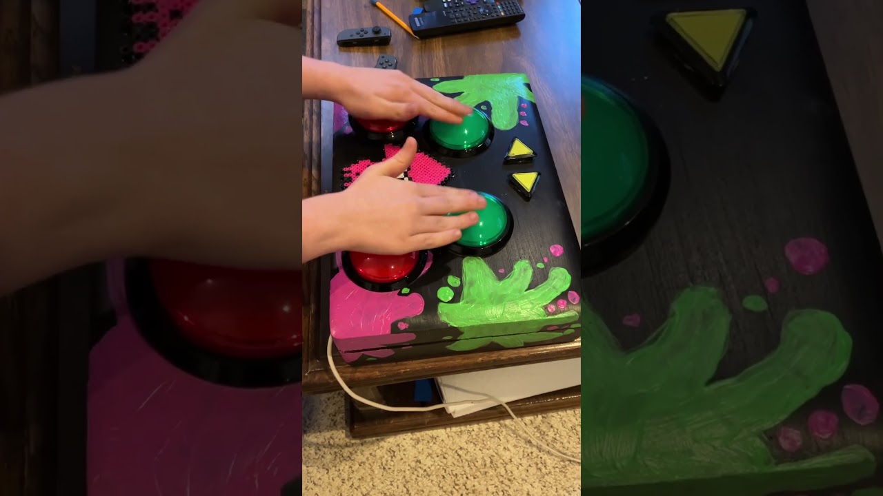
One of my students built this real life Squid Beatz 2 controller for the game Splatoon 2: https://youtube.com/shorts/Xx-PWgOwrWg?si=jlUpECdr0eNpKsv8
 versed lava
scarlet pelican
One of my students built this real life Squid Beatz 2 controller for the game Sp...
versed lava
scarlet pelican
One of my students built this real life Squid Beatz 2 controller for the game Sp...
Do you teach a general engineering class? It sounds fun
scarlet pelican
versed lava
Do you teach a general engineering class? It sounds fun
At Georgia Tech we have a progarm called "Vertically Integrated Projects," which are faculty led student teams that do cool stuff where the students get class credit. The students are encouraged to sign up for it over multiple semesters, so there's some continuity as new students getting up to speed can be helped brought up to speed by students who have been on the team a while
scarlet pelican
versed lava
Do you teach a general engineering class? It sounds fun
I have a VIP team called "Retrofuturistic Hardware: Music, Gaming, and Computing" https://www.vip.gatech.edu/teams/vw9

Modern electronic devices are powerful but uninspiring; they are ubiquitous but ephemeral. We will design and fabricate devices for music production, gaming, and computing sparked by real-world...
scarlet pelican
versed lava
Do you teach a general engineering class? It sounds fun
We also restore and program vintage computers and came consoles. We build a lot of custom arcade controllers, you can see more here: https://www.youtube.com/playlist?list=PLOunECWxELQRNu0a2vS3iJ6OmM_7JOAqP
exotic sierra
scarlet pelican
At Georgia Tech we have a progarm called "Vertically Integrated Projects," which...
I wish I had this 🤯
versed lava
scarlet pelican
At Georgia Tech we have a progarm called "Vertically Integrated Projects," which...
That sounds like a great resume builder. I always look for that kind of stuff when I'm helping hire for green positions
 grave owl
Added multiple new functions as of about ten minutes ago with version 1.0.2
GitHub
Tool to automate Wash>Reaver workflow with cyberpunk themed output. - d3k4-k3rb3r0s/CarWash
 grand jay
64x64 HUB75 with an old plasma demo ported to Protomatter on nRF52840. there’s some level shifters under that big pile of ribbon cables (needed due to 3.3V logic not playing nice with the matrix)
 native inlet
scarlet pelican
One of my students built this real life Squid Beatz 2 controller for the game Sp...
native inlet
scarlet pelican
One of my students built this real life Squid Beatz 2 controller for the game Sp...
heck yeah
i don't usually do rhythm game stuff but i love splatoon
exotic sierra
RPiano V1 is fully assembled and glamorously photographed 🤩


If you’re interested in this cute little piano, I’ll be selling it through my shop and as with most everything I make, it’ll be open source with schematic and whatnot available soon! https://www.oakdev.tech/store/p27/PREORDER_-_RPiano_-_Learn_And_Make_Music_Maker.html#/
Oak Dev Tech
Oak Development Technologies or Oak Dev Tech is a hobby and DIY electronics maker specialized in modularized breakouts for rapid prototyping and hobbyist makers.


 vernal vigil
Wiring up a synth module prototype while I watch JP's stream

 gusty shard
Love the look.

 warped siren
Uh oh, someone put the Death Star plans on Github! https://www.reddit.com/r/arduino/comments/1cjz81d/death_star_plans_code_on_github/
Reddit
Explore this post and more from the arduino community
gusty shard
Many Bothans died to bring us this information.
north mural
Running on an Adafruit ESP32-S3 Feather. Hardware acceleration only really works with vector fills. It says it can do images but I haven't experimented with that yet and I think that feature only works with 16-bit parallel mode. Most microcontrollers are running 8-bit (FourWire) SPI mode. Camera doesn't adequately capture how fast the refresh is due to framerate differences. It's so fast the RGB cycles become a blur. EPILEPSY WARNING: RAPIDLY CHANGING FLASHING COLORS
I said ra8875 display, that wasn't correct. The RA8875 is a display driver board. The actual display is just a 40-pin 7" SPI TFT display.
exotic sierra
(Bright flashing color notice: if you have issues with epilepsy, this video has bright flashing lights which might cause a trigger)
north mural
exotic sierra
(Bright flashing color notice: if you have issues with epilepsy, this video has ...
Thanks, I put a warning on it now.
exotic sierra
north mural
Thanks, I put a warning on it now.
Great demonstration otherwise 😎
I’ve been wanting to use larger displays so the possibility of faster updates is enticing
north mural
I'm going to come up with more examples to add to the library. Something less burning on the eyes.
Yes it's very enticing but the lack of displayio makes it feel like the old basic gfx library from like a decade ago. a TON of work to be done for this driver board but the potential has me really excited, I'm just scratching the surface.
It reminds me of the potential for kmatch's HackTablet but the problem there is not everyone can get one. With something like this it can be made widely available.
 late kraken
Testing using extracted icons from the MaterialIcons TTF font.
 north mural
Here's the OSWHLab link for the board I brought onto Show & Tell last night. Triple adapter that allows you to use any combination of Feather + Pi Pico + QT Py or add-on boards. https://oshwlab.com/djdevon3/st7796s-triple-adapter

In EasyEDA open source hardware lab, open source square pools all kinds of electrical design engineerings together to realize resource sharing easily.
 lean elbow
north mural
Here's the OSWHLab link for the board I brought onto Show & Tell last night. T...
lean elbow
north mural
Here's the OSWHLab link for the board I brought onto Show & Tell last night. T...
This is sweet!
 unreal mica
it's sort of based on the Si5351A breakout board by Adafruit, same header/pinout (with 2 additional) at least, but a new design with extra features, including an I2C RTC IC and larger (1A) 3.3V regulator that outputs to one of those extra pins; made it to add RTC (and 3.3V) to an existing design that had no other way to easily add it without having to buy a whole new one :3
 late kraken
Current UI showing live data. The space at the bottom will be a spark line of the last series of data
 north mural
That’s great. Love the icons.
late kraken
thanks
I cut up the value display into 3 text labels so that I could get a "proportional" font treatment for the decimal
 gray inlet
I got a bag from a bakery, and it was pretty enough that I wanted to use it as a gift bag. However, I wanted to cover up the name of the bakery.
So, I glued some cotton balls onto the bag to cover up the name, and turn the printed cloud into a three-dimensional cloud.
But before I glued on the cotton balls, I cut a couple of small holes on each side of the bag. (The two sides of the bag are identical.) On each side of the bag, I mounted a 130mm warm white "nOOd" (Adafruit #5504). On the inside of the bag, I wired up the two nOOds in series with each other, and in series with an appropriate resistor, and connected the circuit to a 9V battery snap.
So, now I have a bag with a glowing cloud on each side, which is powered by a 9V battery inside the bag, hidden underneath the present.

 exotic sierra
I made a 2bit trainer MCU on an fpga
 burnt wyvern
scarlet pelican
One of my students built this real life Squid Beatz 2 controller for the game Sp...
burnt wyvern
scarlet pelican
One of my students built this real life Squid Beatz 2 controller for the game Sp...
I always thought the button layout for that minigame was really confusing on the stock controller, so its cool to see a dedicated device for it!
late kraken
Latest UI test with a spark line!
 exotic sierra
I made a 2bit trainer MCU on an fpga
exotic sierra
exotic sierra
I made a 2bit trainer MCU on an fpga
I’ve put the trainer CPU up on GitHub for anyone to try out: https://github.com/skerr92/O2-Trainer

GitHub
Home of the OASIS 2b Trainer CPU. Contribute to skerr92/O2-Trainer development by creating an account on GitHub.
 quartz canyon
exotic sierra
I’ve put the trainer CPU up on GitHub for anyone to try out: https://github.com/...
quartz canyon
exotic sierra
I’ve put the trainer CPU up on GitHub for anyone to try out: https://github.com/...
Maybe populate main branch?
exotic sierra
When I’m done developing 0.1.0 I will
I thought I shared the branch 💀
GitHub
Home of the OASIS 2b Trainer CPU. Contribute to skerr92/O2-Trainer development by creating an account on GitHub.
quartz canyon
Can you tell me what it does?
exotic sierra
Linearly executes 8 bit wide instructions. I can Add, Subtract, AND, and NOT for ALU operations, store intermediate in the 2b x 4 register file, store and read from a 2b x 16 bit of memory. And has the ability currently to load new instructions by asserting instr_we
Still some work to do on it, but it does run a simple program
quartz canyon
Yeah, I see. Thank you for explanation.
https://github.com/skerr92/O2-Trainer/blob/0.1.0/src/alu.v#L11-L14
https://github.com/skerr92/O2-Trainer/blob/0.1.0/src/instr_mem.v#L10-L26 --test program?
Plus some state machine in https://github.com/skerr92/O2-Trainer/blob/0.1.0/src/cpu.v#L60-L105
exotic sierra
quartz canyon
Yeah, I see. Thank you for explanation.
https://github.com/skerr92/O2-Trainer/b...
Yup, pretty simple stuff for now 🙂
I’m going to release 0.1.0 today sometimes, start 0.2.0 which will include some additional operations like jumps
quartz canyon
exotic sierra
Yup, pretty simple stuff for now 🙂
Simplicity is very hard thing to keep.
I like this code because I can read it in like 10 minutes.
exotic sierra
The goal is to keep it very simple
quartz canyon
So there is no difference between code and data? Can we generate random say 5-byte programs for given test data until we get program that does ((a OR b) + 2)?
Also you don't have comparison and jump?
exotic sierra
quartz canyon
So there is no difference between code and data? Can we generate random say 5-by...
Those will be coming, right now I was just using an 8 bit wide instruction which kind of limits what can be done
0.2.0 will widen the instruction to 10 or 12 bits.
This will allow memory to at least double, instructions to double, and ALU operations to double
Eventually this will encompass the same instructions as DungV, which is the first processor I made implementing the OASIS instruction set
Which I will eventually push up the changes to that 💀 I realize it’s been 5 months since I’ve done anything
OASIS = Open Architecture Simplified Instruction Set, sort of a pet project to develop a flexible architecture for CPU
quartz canyon
exotic sierra
Those will be coming, right now I was just using an 8 bit wide instruction which...
I mean the idea is to generate program that transforms input to desired output.
Say I want program that XORs two 2-bit operands. I know it's possible in NAND and NOR but I don't wish to think about formulae.
So I wish
do
  is_correct = true
  code = generate_random(5) // 5 bytes length
  for a = b00, b11
    for b = b00, b11
      mem[0] = a
      mem[1] = b
      execute(code, mem)
      if (xor(a, b) != mem[2])
        is_correct = false
until is_correct
print_code(code)
Yeah, that should be possible as xor will be added
north mural
Pulled the trigger on a PCB design that acts as a simple step down from 27VAC to 24VAC. The irrigation timer I have has a built-in 24VAC transformer but it actually outputs 27VAC. According to the irrigation timer documents it requires a minimum distance of 15 feet to connect a pump-start relay (PSR). Why 15 feet? Because it needs that distance for voltage drop to bring it closer to 24VAC. Since my timer is only 2 feet from the PSR I'm going to introduce some resistance to make it think it's 15 feet away. This is a solution to a problem that only affects a few people but when you have this issue you can either run 15 feet of cable just to connect to a PSR 2 feet away or do something like this. A variable resistor or potentiometer might be a better solution I'll look into in the future. For now I just need it as a proof of concept prototype.

The values printed on the 3D models are incorrect. I've verified the actual components are a 10 ohm and 82 ohm resistor.
 stark latch
Tiny robot arm WIP. Uses 6 SG90 servos: base, shoulder, elbow, wrist flex, wrist rotate, grip. With arm fully extended, it's about 200x100x60mm. Weighs about 105g. The "fingertips" are 1x2mm.
Will eventually be controlled by a Feather M0 Express, which will sample potentiometers attached to a much larger (4x scale?) controller arm, translating and scaling the inputs to drive the robot arm.
And, yes, I'm aware of how much it looks like a deranged robot bird.
 pallid saffron
nah -- i like it a lot, but i'm pretty big on deranged (been meaning to post this for a bit) -- this is the Autonomous Servo Servant Home Assistant Thingie (uses MQTT and HA for remote control) -- say "hello", Thingie (i'll let y'all work out the acronym yourselves)
i think i may steal the "fingers" setup you have there ...
north mural
Beautiful acronym. 👏
pallid saffron
i was pretty nefarious for those when i was workng: there's a whole bunch of very silly named software apps running Your Local Cable Systems 😈
stark latch
...and I just now found out that the Arduino servo library, in addition to the write() method, which takes integer degrees, has a writeMicroseconds() method that translates to increments of about 0.18 degrees. That means that, with a bit of reprogramming...
a) the "fingertips" could separate in increments of about 140 micrometers instead of 1mm or
b) the fully-extended arm, rotating at the shoulder, could have a precision of 0.35mm instead of 2mm
So a six-fold increase in precision just by changing a few lines of code. That might actually make this thing practical.
pallid saffron
don't know if you were aware of the origins of your project's concept -- https://en.wikipedia.org/wiki/Waldo_(short_story)

"Waldo" (1942) is a short story by American writer Robert A. Heinlein, originally published in Astounding Magazine in August 1942 under the pseudonym Anson MacDonald. It is available in the 1950 book Waldo & Magic, Inc. (as well as other collections). Both stories in that collection involve magic but are otherwise unrelated.
The essence of the ...
stark latch
pallid saffron
don't know if you were aware of the origins of your project's concept -- https:/...
Yep! I had a copy of "Waldo & Magic, Inc." sometime in the 80s I think.
pallid saffron
stark latch
Yep! I had a copy of "Waldo & Magic, Inc." sometime in the 80s I think.
i had the crazy "matching" set of heinlein books that ace put out in the late 70's -- before he got totally [expletive] weird
stark latch
pallid saffron
i had the crazy "matching" set of heinlein books that ace put out in the late 70...
Yeah, some of his stuff did not age well. 😄
alpine token
MIDI Spoon Piano w/ Raspberry Pi Pico, circuitpython, & touch sensing: https://www.youtube.com/watch?v=52Xef2qi53g Big props to @warped siren for the code as I literally just plunked what he wrote into my design.

How I made a MIDI spoon piano with a Raspberry Pi Pico and capacitive touch sensing
#raspberrypi #3dprinting #music
ToC:
0:00 - Intro
0:34 - Design
1:00 - Laser & Cuts
2:02 - 3D Printing issue
2:33 - Finish and assembly
3:46 - Initial trial
5:09 - Redo and add octave/mod control pad
7:38 - Trial with control pad
8:47 - Ben tries it out
10:49 -...
stark latch
Robot Arm - Test #1
https://www.youtube.com/watch?v=uZeP9UainAQ

This is a tiny robot arm I designed, made from six SG90 servos and a bunch of 3D-printed parts.
With them arm fully extended, it's about 200x100x60mm. It weighs about 105g. The "fingertips" are 1x2mm.
It's currently being controlled by an Adafruit M0 Express, reading six 10k potentiometers.
north mural
I thought there would be too much weight on them with 3D printed brackets. Good to know those servos can take it. great design.
stark latch
north mural
I thought there would be too much weight on them with 3D printed brackets. Good...
Thanks! I think I need to upgrade the servos, though. Those are SG90 knockoffs I picked up on Amazon. I might pick up a couple TowerPro digital SG90 servos and see how different they are.
 marble mantle
get mg90 version, with metal gears
pallid saffron
i swapped to cheap MG90S -- they have the same basic footprint as the SG90's but metal gears, different spline, and (from my experimenting on adjusting the trim values) a 200 degree full swing -- the stall torque is about the same, but they play nicer with small over-loads
vernal vigil
"Get a second monitor," they said. "It'll make programming easier."

I'm not convinced.
pallid saffron
size does matter in some cases
bitter dome
pallid saffron
size **does** matter in some cases
Make the font very small and get magnifying glass 🙂
marble mantle
1-pixel font works great
 eternal swift
"128x64 ought to be enough for anybody" (Jonathan Frakes III)
 earnest flax
I rewrote the POV code and made it more user friendly! @adafruit’s image_load and displayio libraries make file parsing in #CircuitPython easy! I hope this code unlocks some new projects ideas for Breadstick owners 🌈🪄I can’t wait to see what you all make!
 Twitter
·
earnest flax
Twitter
·
earnest flax

Raspberry Breadstick POV Demo Code https://learn.breadstick.ca/breadstick/breadsticks/raspberry-breadstick/code-examples/pov-wand
dark cairn
Native Beryllium OS console support for the display and keyboard of the Cardputer.
So it's basically a laptop now.
You can go online, download files, edit documents and play games.
What else could you need?
RAM? No you don't.

(clearer screen photo)

Since it has pins exposed too, you can even use it to connect to other boards via uart..
clever stone
Using what I learned from writing my CircuitPython asyncio input handler, the user experience for the 2024 eChallengeCoin text adventure game is SOOOO much better.
As you make your way thru the Dark Labyrinth. The ePaper display will periodically update your map!
(asyncio example: https://gitlab.com/bradanlane_cp/asynchronous-io)
 sonic fractal
The RECH-1, one of chiles nuclear reactors


 dark cairn
Emergency power bank.
And I once again repeat: Grove is USB-A for microcontrollers.
Prove me wrong.

It's 1500 mAh, so it's not bad.
vernal vigil
First test - it works 👍

 cunning lava
I got jealous of the people who had all those ribbons added to the bottom of their conference badges, so I decided to make a blinky ribbon for myself for next time.
 exotic sierra
Doing some RP2040 + iCE40 examples 😎
marble mantle
reverse engineering some smart servo protocol...
 exotic sierra
marble mantle
reverse engineering some smart servo protocol...
exotic sierra
marble mantle
reverse engineering some smart servo protocol...
How’s the rigol scope working out for you?
marble mantle
quite well except I didn't yet find a simple way to hook it to a computer.
PulseView can't see it, and Rigils official software is for Windows only (I use Mac).
But I didn't spend much time on this.
exotic sierra
I’m considering a 200MHz scope from Siglent
I want to do some Ethernet stuff (125MHz per channel or so) so a 200MHz scope would work I think.
exotic sierra
Personally I’d love a Teledyne Lecroy but I don’t have the budget for that 😀
marble mantle
maybe a used one?
exotic sierra
Hehe, even used ones are pretty pricey. One day though 🙂
 peak marlin
I made a thing - the code needs some work but it works:
https://github.com/DerBroader71/repomonitor
GitHub
Repository monitor using Sunton ESP32-2432S028R and CircuitPython - DerBroader71/repomonitor
if anyone remembers teletext https://en.wikipedia.org/wiki/Teletext
 jade path
peak marlin
I made a thing - the code needs some work but it works:
https://github.com/DerBr...
jade path
peak marlin
I made a thing - the code needs some work but it works:
https://github.com/DerBr...
I don't know if you're interested, but that looks like the so-called "cheap yellow display", you might want to submit it to https://github.com/witnessmenow/ESP32-Cheap-Yellow-Display/blob/main/PROJECTS.md
GitHub
Building a community around a cheap ESP32 Display with a touch screen - witnessmenow/ESP32-Cheap-Yellow-Display
vernal vigil
protip: If you're making your own cables using header pin + socket connectors, paint a colourful stripe on one end of the connectors so you never plug them in backwards
 sand grotto
vernal vigil
protip: If you're making your own cables using header pin + socket connectors, p...
sand grotto
vernal vigil
protip: If you're making your own cables using header pin + socket connectors, p...
Just had to buy some more tipex pens for that reason, sharpie on black connectors doesn't quite cut it 😉
exotic sierra
Video that’s too long for my non-nitro account https://x.com/oakdevtech/status/1795617281470505158
Doing another example with the RPGA Feather, this time getting a pseudorandom 3 bit number from the FPGA into the RP2040.
 Twitter
·
Twitter
·
The one time I get no link preview boo..
Okay, anyway that link is to a video demonstrating getting an output from the FPGA to the RP2040 on the RPGA Feather
 odd panther
Well this is what I was able to make

 restive forum
odd panther
Well this is what I was able to make
restive forum
odd panther
Well this is what I was able to make
Max Headroom cosplay when???
odd panther
restive forum
Max Headroom cosplay when???
Honestly, not a bad idea
vernal vigil
when you're not sure about the pin assignments
 vernal vigil
(turns out I guessed right woohoo)
Achievement Unlocked: Put the Darn Heatshrink Tubing On Before Soldering Both Ends

 warm crater
Hey all I want to do another show and tell next week and I need to come up with a better way to point a camera at the project instead of trying to aim my laptop camera at it. Can I use my iPhone or something? What would be best would be an external camera on a tripod so I can have both hands to much with the project on camera.
 livid copper
They make a little tripod that can hold up a phone
 cedar trellis
warm crater
Hey all I want to do another show and tell next week and I need to come up with ...
cedar trellis
warm crater
Hey all I want to do another show and tell next week and I need to come up with ...
You could get something like this for your phone, flexible gooseneck that can be adjusted in any direction.
 clever stone
@warm crater - the direction you need the camera to point is often the key to deciding what to use.
I use current (and old) smartphones as cameras for stream through OBS. I have two solutions for holding phone cameras:
- Down facing camera uses a 3D printed platform
- Forward and arbitrary angle facing camera uses a locline clamp
Down camera solution:
https://gitlab.com/bradanlane/models


 stark latch
Robot Arm Test 2
https://www.youtube.com/watch?v=2F_dEwJgQ4A

This is a tiny robot arm I designed, made from six SG90 servos and a bunch of 3D-printed parts.
Since the previous test, I've:
- upgraded the servos to Tower Pro SG90 digital servos
- printed a controller arm
- strapped down the wiring a bit
It's still a bit jittery. Some of that seems to be noise on the wires from the controller, some is just...
late kraken
Deep sleep wake from button press! My first physical button interface 😁
stark latch
stark latch
Robot Arm Test 2
https://www.youtube.com/watch?v=2F_dEwJgQ4A
STL files and SCAD source available here in case anyone wants to make one: https://www.printables.com/model/898783-tiny-robot-arm
For the video, I'm using a Feather M0 but any sort of device that can control 6 servos would do.

Printables.com
A very small robot arm using six SG90-style servos | Download free 3D printable STL models
 magic matrix
https://www.youtube.com/watch?v=iatpEbRMiGw&t=22s
final year project, electronics engg.
open for suggestions

Final Year Project made by Electronics Engineering Students at UET Taxila.
Waqas Ahmad
20-enc-10@students.uettaxila.edu.pk
Toheed Husain
20-enc-46@students.uettaxila.edu.pk
Amir Khan
20-enc-51@students.uettaxila.edu.pk
G-Code sender Application:
https://github.com/MToheedHussain/G_code-Sender
exotic sierra
Respinning IcyBlue FPGA to use an even nicer Lattice FPGA, a Crosslink-NX


Still a work in progress but wow doing the power on this thing was wild
Lots of capacitors and ferrite beads
sand grotto
Circuitpython ESP32 BLE sending SHT3x data (on T-DisplayS3) to Adafruit BlueFruit Connect app. Thanks for the work Scott, seems to pass initial halt and catch fire test, thrilled doesn't begin to cover it https://youtu.be/BnHAt1iiKOM

Adafruit Bluefruit Connect app running on an Apple iPhone, connected to a CircuitPython board (an Espressif ESP32-S3 based LilyGo T-Display S3). A Sensirion SHT3x series of Temperature and Humidity sensors is attached to the StemmaQT (JST-SH 4pin) I2C port, transmitting the sensor data over Bluetooth Low-Energy (BLE) and being graphed in the @ad...
sand grotto
sand grotto
Circuitpython ESP32 BLE sending SHT3x data (on T-DisplayS3) to Adafruit BlueFrui...
Moved on to reliable hard-fault 😄 Using an LSM303AGR (accelerometer) with the BLE Web Dashboard, hard fault as soon as it tries to start notifications from the AccelerationService, although I'm also seeing a console message claiming the web dashboard is attempting to update the measurement period which happens before notify start (I set it to 500 ms period instead of 100 in code so shouldn't be required, but maybe not part of broadcast info so writes desired value rather than read then write if incorrect).
Modified example to skip non-available sensors and have 3 Accelerometer options, https://github.com/tyeth/Adafruit_CircuitPython_BLE/blob/web-bluetooth-dashboard/examples/ble_bluefruit_web_dashboard.py, I'll capture more details before filing an issue.
BLE Web Dashboard: https://kind-decisive-paw.glitch.me/
sand grotto
Feather ESP32v2 working well too (for temp+humidity+button+neo)
 exotic sierra
More progress on the Feather NX

 sand grotto
exotic sierra
More progress on the Feather NX
sand grotto
exotic sierra
More progress on the Feather NX
🤩 What's on it, couldn't find with a quick search?
Think this might be the year I do a PCB (first since I was a kid)
exotic sierra
sand grotto
🤩 What's on it, couldn't find with a quick search?
Think this might be the year...
It’s a Lattice Crosslink-NX FPGA their LIFCL-40 line I believe.
Based around this one here: https://www.digikey.com/en/products/detail/LIFCL-40-7BG256C/12751829

DigiKey Electronics
Order today, ships today. LIFCL-40-7BG256C – CrossLink-NX™ Field Programmable Gate Array (FPGA) IC 163 1548288 39000 256-LFBGA from Lattice Semiconductor Corporation. Pricing and Availability on millions of electronic components from Digi-Key Electronics.
sand grotto
Aye, not cheap, fair play. I'm still FPGA shy for now, but tempted for years. Need a real reason to have one, some dynamic reprogrammable reason (DSP seemed a lot of cases or video things). One day 😁
exotic sierra
sand grotto
Aye, not cheap, fair play. I'm still FPGA shy for now, but tempted for years. Ne...
Yeah, this FPGA will be able to do some crazy stuff like run a RISC-V softcore, run litex or even small Linux distros
There are cheaper variants as well that come in QFN packages
sand grotto
exotic sierra
Yeah, this FPGA will be able to do some crazy stuff like run a RISC-V softcore, ...
How beefy is that softcore, what kind of modules / IP gets loaded potentially...
exotic sierra
Well, you can do SGMII (L2 MAC protocol), MIPI, CSI, you can end up doing other things like RGMII which is also Ethernet.
The fabric supports 1.25G SERDES
You also get support for LPDDR3
The MIPI PHY can do 10G per PHY, and there are 2x on the FPGA
exotic sierra
It’s big application is like edge ML/AI applications with connected cameras
sand grotto
Okay, that's something that could push me, I know GPUs aren't optimised for TPU work, and I have dreams of identity detection amongst squirrels and birds (to squirt with water when feeding at bird feeders too long - daily limit)
exotic sierra
😄
sand grotto
Hehe, it's the funny mischievous and perverse that fuel me, second to the need to understand things
exotic sierra
Im working on a few designs with this FPGA too. I should make a module that supports hooking up cameras and gigabit Ethernet
sand grotto
exotic sierra
Im working on a few designs with this FPGA too. I should make a module that supp...
Sensible combination
exotic sierra
I broke out one of the PHY that does MIPI/CSI/DSI but I would probably need a crossover board to ensure you could use it with camera modules
sand grotto
This is it, nothing is simple in FPGA-land
exotic sierra
That’s just high speed io land in general
😄
But, as long as the designer does the right things, you should only have to hook things up
sand grotto
That's it, follow the design rules (a lot automated these days) and fingers crossed it's all gravy (lol language is funny)
 raven shale
This is my (third) iteration of Adafruit's Maypad + KB2040 tutorial project. The hardware was one and done, but I went through KMK (following the tutorial), then wrote my own circuitpython script using the keypad library (to learn), and finally went back to QMK since they made it substantially easier to use on the RP2040 with VIA support. I printed out a case and keycaps for it as I'll be sending it off as a gift to numpadless friend.
 exotic sierra
More progress on the Feather NX
exotic sierra
exotic sierra
More progress on the Feather NX
Back looks better now
 clever stone
@sand grotto - if you are not ready to jump to FPGA, then I would consider digging into what is possible with the PIO of the RP2040 - it is capable of doing some impressing tasks: VGA, DVI, signal generator, CANbus, USB, and more.
sand grotto
clever stone
<@375674153203662851> - if you are not ready to jump to FPGA, then I would consi...
100% good advice. Yeah I should probably explore something simpler in PIO before diving into verilog/vhdl etc, I'd hoped to dive into the ULP cores in esp-land, but keep getting distracted by new shiny things (BLE on esp32 this week)😄
clever stone
@sand grotto - new MCUs are a Maker's "SQUIRREL" 😜
cunning lava
cunning lava
I got jealous of the people who had all those ribbons added to the bottom of the...
pcbs arrived
 clever stone
Combining the CircuitPython deep sleep feature with an ePaper display and an accelerometer interrupt ...
 eternal maple
The CG-35 retro RPN calculator project. CircuitPython running on an ESP32-S3 with a 3.5-inch capacitive touch FeatherWing display. https://youtu.be/bBqApLaqzmY

Patterned after a popular retro Reverse Polish Notation (RPN) calculator, the CG35 is a CircuitPython-based version implemented on a 3.5-inch FeatherWing capacitive touchscreen display. An Adafruit ESP32-S3 Feather provides the computational power.
The calculator's Learn:Playground page: https://adafruit-playground.com/u/CGrover/pages/cg-35-a-retro-rpn-calculator
exotic sierra
Welp, I think it's basically ready to order at this point
 cunning lava
pcbs arrived
cunning lava
cunning lava
pcbs arrived
The LEDs arrived too.

 ashen iron
I'd like to present my Feather compatible ESP32 board (with STEMMA QT port, too) for solar & battery powered projects: ESP32-S3 PowerFeather.
Features a Texas Instruments BQ25628E as charger IC, with an on-board fuel guage Onsemi LC709204F. Low current deep sleep, under 20 uA.
Has an ESP-IDF & Arduino helper library for interfacing with the BQ25628E and LC709204F.
I made a showcase video of it: https://youtu.be/VF9AFk1Hf88

Showcase video of ESP32-S3 PowerFeather, a low power ESP32 dev board for solar and LiPo/Li-Ion battery-powered IoT projects. It features an ESP32-S3-WROOM-N8R2, Texas Instruments BQ25628E battery charger IC, and an on-board battery fuel gauge Onsemi LC709204F.
Timestamps:
0:00 Introduction
1:18 Part 1 - Hardware Tour
11:40 Part 2 - Power Feat...
Please excuse the production quality - as I don't really have a setup for media production like this 😄
Hopefully the information is good, though.
More info in the docs site: https://docs.powerfeather.dev/
Features & Specifications
 eager atlas

I updated some stock ticker matrix cpy code for a 64x64 display and now I can wake up and see if I'm a millionaire yet.

GitHub
Contribute to SamDamDing/MatrixPortalStockTicker development by creating an account on GitHub.
exotic sierra
We’re on the same wavelength @clever stone 😋
I posted cool stuff on Xitter and was like, “I should share this on the Adafruit discord” and here you are after posting on Xitter too 😂
clever stone
I am working on two designs that are collectively referred to as "Explorer Badges". They are an RP2040 boards either loads of capacity for exploring what is possible with programming microcontrollers with CircuitPython.
The boards support both PWM and I2S audio. Here is an audio demonstration ...
exotic sierra
RPGA Feather is a thing of beauty. RP2040? Easy choice. ICE40 FPGA? Accessible and well supported. Together? An amazing embedded experience.


 clever stone
I am fascinated by what could be possible with FPGA 🤩
exotic sierra
Now all I have to do this weekend is finish rounding out documentation, examples, etc.. and also waiting for Tindie approval
marble mantle
exotic sierra
Now all I have to do this weekend is finish rounding out documentation, examples...
do you still sell through your own store? or Tindie only?
exotic sierra
marble mantle
do you still sell through your own store? or Tindie only?
Switched to just Tindie for now. Maintaining my web store was a bit more expensive than I was expecting with sales being pretty slow.
When they pick up, I’m going to probably do my web store again
molten jewel
O_o really? what are the costs of your own store?
etsy steals almost 20% of my sale whihc is quite high
ashen iron
Aside from ESP32-S3 PowerFeather, I'm also working on a LoRa FeatherWing, featuring E22-900M22S (SX1262) + PIC18.

Why the PIC18? To allow some degree of pin remapability, in case of stacking multiple of these.
late kraken
After much learnings, I am driving both displays! eInk using the ThinkInk feather friend over SPI and an OLED over I2C
 exotic sierra
I've been working on a local parts management web app to help me track parts. I've made it so far to support adding individual parts, a list of parts in a csv file, as well as being able to update parts, and add basic project management (name, desc, repo link). This will be getting better over time. But I figured i'd share it here 🙂 https://github.com/skerr92/my-reels


GitHub
Home of local parts management server, MyReels. Contribute to skerr92/my-reels development by creating an account on GitHub.
 ancient skiff
I designed and 3d printed an enclosure for a friend's retrocomputing project. You'll be able to load code on a microcontroller a nibble at a time by pressing the 0-9 A-F keys on the left, and access different modes and actions via the 4 buttons + 4 toggle switches.

 amber merlin
I made this video showing off a board replacement and firmware for one of those buddhist chanting boxes - and then I realized that adafruit stocks them! so maybe of interest to the folks here: https://www.youtube.com/watch?v=_xELX-fj47k

A music box that you can script with lua.
https://github.com/jonbro/aleatorium/
exotic sierra
I’ve added a preliminary project part list table to the projects page. Still some work to do in order to make this more cohesive and not just a spam of parts in partlists

 gritty owl
I made my bathroom a little bit funky. 🙂
I designed and did most of the work by myself and my gf. Not just the electronics, but everything beside the tiling.
I used wled, ethert Dig Uno and SK6812 ledstrip

 lost remnant
Built a USB PD CH224K based WLED controller with 12V and 5V output. I'm fairly new to circuit board design so I'm glad it worked with minimal issues. Hacked an aliexpress purchased infinity mirror LED thing to put on WLED animations. The bouncing balls one is fun. Going to redesign it later to ditch the D1 mini in favor of an ESP32 on the board but I didn't want to complicate the project further given a lot of it was new to me and I was fearful it wouldn't work as-is.


 lost remnant
Built a USB PD CH224K based WLED controller with 12V and 5V output. I'm fairly n...
lost remnant
lost remnant
Built a USB PD CH224K based WLED controller with 12V and 5V output. I'm fairly n...
I'm a fan of the CH224K -- WeAct makes a CH224K board they sell fairly cheap with a dip switch allowing for voltage toggle -- useful for all sorts of projects. https://oshwlab.com/wagiminator/ch224k-usb-pd-decoy Stefan Wagner also has an open source version available.
 cedar timber
exotic sierra
RPGA Feather is a thing of beauty. RP2040? Easy choice. ICE40 FPGA? Accessible a...
cedar timber
exotic sierra
RPGA Feather is a thing of beauty. RP2040? Easy choice. ICE40 FPGA? Accessible a...
What are you intending to do with the FPGA?
exotic sierra
cedar timber
What are you intending to do with the FPGA?
Whatever you can think up, run a softcore CPU, DSP core, etc..
I have a hobby business so I sell things that I think are pretty cool. Some people also think they’re cool and buy them
burnt wyvern
Not sure if this is a project that's suitable enough for this channel, but the switch for checking if the disc tray is closed in my Nintendo GameCube broke and I couldn't find a reasonably priced OEM or third party replacement (around $25 USD without tax or shipping!!) So I decided to improvise, I harvested a limit switch from a dead 3D printer and with a lot of measuring and iterations of 3D prints (and a bit of cutting the shell, sadly) I managed to make my own! And yeah, it just barely fits.
 cedar timber
exotic sierra
I have a hobby business so I sell things that I think are pretty cool. Some peop...
cedar timber
exotic sierra
I have a hobby business so I sell things that I think are pretty cool. Some peop...
Oh awesome! I have great respect for business owners. Do you have an online shop?
cedar timber
burnt wyvern
Not sure if this is a project that's suitable enough for this channel, but the s...
Nice job! Looks legit
exotic sierra
cedar timber
Oh awesome! I have great respect for business owners. Do you have an online shop...

Tindie
Oak Development Technologies or ODT is a small form factor hobby electronics developer and manufacture based in the United States! We work …
burnt wyvern
cedar timber
Nice job! Looks legit
Thanks!
exotic sierra
I'm really excited for Alpha Release 0.0.3 for MyReels! This update brings the ability to "build" projects. What this does is allows you to select from current projects and it will subtract the number of parts needed to build your project from global inventory. It's pretty straightforward. https://github.com/skerr92/my-reels/releases/tag/0.0.3

GitHub
What's Changed
Add project partlists by @skerr92 in #6
alpha-0.0.3 feature update by @skerr92 in #7
Full Changelog: 0.0.2...0.0.3
If you try it out, let me know what you think 🙂
 eager flume
I ported doom-nano to an ST7735. Wasn't too difficult but I made a quick optimization that instead of clearing the screen, I draw vertical lines over the parts i've updated (so only those parts are redrawn to the screen), which boosted the FPS from 2 to 10
GitHub
A 3d raycast engine for Arduino. Contribute to simplyrohan/doom-nano development by creating an account on GitHub.
 fringe oak
I had been posting about this in project help but I’ve got the default face done now 🎉
 jovial ocean
Proto!
 shell hawk
I compiled an unofficial CircuitPython port for Docker and I'm hoping some of you can break it. Images are available x86 and ARM.
https://github.com/rgrizzell/docker-circuitpython-linux
If you're not keen on running strange Docker images on your computer, build instructions are in the README.

GitHub
CircuitPython container image for Docker and other runc-based container orchestrators. - rgrizzell/docker-circuitpython-linux
 glad roost
shell hawk
I compiled an unofficial CircuitPython port for Docker and I'm hoping some of yo...
glad roost
shell hawk
I compiled an unofficial CircuitPython port for Docker and I'm hoping some of yo...
have you seen this also? https://github.com/adafruit/circuitpython/pull/9349
ashen iron
ashen iron
Aside from ESP32-S3 PowerFeather, I'm also working on a LoRa FeatherWing, featur...
Assembled 3 pcs for now for developing the PIC18 firmware...

 cursive egret
I figured I’d share my completed Spaceship Earth build. I mapped the LEDs to a 2D matrix so I could display custom patterns. I created a playlist that syncs up with the EPCOT 40th Anniversary Points of Light Show.

This is a model of Spaceship Earth at EPCOT. It was 3D printed and is lit by NeoPixel LEDs and powered by an Arduino running the WLED software.
I re-created 32 presets and timed them out on a playlist to closely match the EPCOT 40th Anniversary Points of Light show on the real Spaceship Earth.
Thank you to @adafruit well as Noe & Pedro Ruiz...
cedar timber
Going from a Pi Pico W to the nRF52840 Sense! This should make for an excellent brain for the rover 😁
 lean elbow
Built another "top-secret" lunchbox. This one is a bit smaller in size and scope than the last one I built, but I like the way it came together more. The idea for this one is to have several old-school telephone switchboard-style puzzles, perhaps as part of a larger suite of puzzles/top-secret devices. Here's a quick peek at a puzzle where you need to make connections with the ports of matching color, before running out of time, or connection attempts.
The idea for a switchboard routing style puzzle box came from an episode of JP's workshop several months ago where he was playing around with similar concepts. Thanks @terse totem!
 terse totem
This is wonderful!!
lean elbow
Thanks John! 😄
lapis jasper
lean elbow
The idea for a switchboard routing style puzzle box came from an episode of JP's...
Very cool! How are you detecting which plugs are plugged into others?
lean elbow
lapis jasper
Very cool! How are you detecting which plugs are plugged into others?
Thanks! The basic idea is that each plug is connected to a GPIO configured as an input with a pullup resistor. Then, periodically, we iterate through each plug's GPIO, changing it to output and setting it low, and then scanning the rest of the input plugs to see if they've been pulled low. If so, we know those two plugs are connected. I can't find the episode of JP's workshop where he was playing with this, but I believe this video was the inspiration https://www.youtube.com/watch?v=Fa_JP8u2bVc
Learn how to create a "Connect the Wires" puzzle commonly found in escape rooms, using an Arduino UNO and some 6.4mm audio connector cables/sockets.
Documentation, including parts list, wiring diagram, and full code listing is available on my patreon page: https://www.patreon.com/playfultech
north mural
Working on a touchscreen for the Rachio irrigation timer. work in progress.
 pallid saffron
how to make a Pi 3 actually work a bit (and top out I2C as well) -- running Kotlin/JVM 😈 for multi-threading
 tired flax
Managed to port a tiny Convolutional Neural Networks to CircitPython. Incredible the RP2040 chip is able to handle a camera , TFT LCD and the neural network while running CircuitPython. I have written a detailed writeup about my project (https://tinyurl.com/45vbwcs4), which contains a workflow that can be used to train models in Tensorflow and port them to CircuitPython. This repository has everything needed for running the model and training new ones: https://github.com/code2k13/cnn_circuit_python .

GitHub
This repository contains code for running Convolutional Neural Networks (CNNs) on CircuitPython. It contains code to train models using Tensorflow on computers and convert them to CircuitPython. -...
lost remnant
https://www.printables.com/model/926922-animal-tags https://www.cranberrygrape.com/3d-printing/animal-tags/ 3D printing related project writeup describing the process of taking an image and turning it into an SVG to then cutout via fusion 360. A pretty simple project so apologies if it doesn't belong here.
lost remnant
lost remnant
https://www.printables.com/model/926922-animal-tags https://www.cranberrygrape.c...
 lean elbow
This is really cool, I was actually planning on trying something like this soon. Thanks for the write-up!
lean elbow
My gf asked me to build her a little gadget to help her remember if she took her meds on any given day. The way it works is she presses the button when she takes her meds, and the device lights up. It uses an RTC to reset the lights every night. Kirby fans might recongnize the audio
Uses a Propmaker RP2040 feather, a clear arcade button modified with a Neopixel, 2 neopixel sticks, and a little oval speaker. Programmed in CircuitPython
quartz needle
That's a great idea
Mine is just one of those med bottle tops with the timer for. When it was last opened
lean elbow
Thanks! This is the design she sent me when she asked me to build it lol. The comic sans in the final build was my idea 😂
 stark latch
Made myself a custom 3D-printed membrane keypad. The controller is a Trinket M0, using the Keypad and Keyboard Arduino libraries to scan the matrix and translate into keyboard events. The key graphics are printed on vinyl adhesive printer paper.

 proven ruin
an em dash key would be so useful.
stark latch
proven ruin
an em dash key would be so useful.
Right? I was using em dashes so much, I built a keypad for it. Granted, I could've just bought a NeoKey and done just the em dash, but why engineer when you can over-engineer? 😄
bitter dome
bitter dome
i was kinda bored so.. here's a donut.
this is the same donut but battery powered

 loud crane
hey guys, I saw adafruit's Neo trinkey rubber ducky, and it didnt seem to work on other devices, and looked like some code could be removed, so I made one that use BOARD.Button rather than whatever they were using, and ported the code to the QT2040 Trinkey, and published it on github:

GitHub
Simple, CircuitPython powered QT2040 Rubber Ducky. Contribute to N-coder82/qtducky development by creating an account on GitHub.
if anyone wants to use
stark latch
Might've gone a bit overboard on this... https://youtu.be/OVDJm5ZllzE

I wrote some OpenSCAD code to generate membrane keypads. Out of curiosity, I tried to see how many keys I could cram onto a keypad about the size of a credit card and have it still (sort of) work. The answer is 60.
The keyboard is about 86×54×2mm. The wiring and microcontroller quite a bit more bulk. And it worked the first time I tried it, mo...
lost remnant
https://www.youtube.com/watch?v=umzO1WO6qNo
https://www.cranberrygrape.com/mini-projects/unihiker-remote/
Fairly simple project just making a remote control for an omni-directional mecanum car using my DFRobot Unihiker. The car I used comes with a Banana Pi PicoW S3 which is primarily geared towards CircuitPython. Relied on the libraries included by the car's manufacturer for a lot of the heavy lifting here.
lost remnant
lost remnant
https://www.youtube.com/watch?v=umzO1WO6qNo
https://www.cranberrygrape.com/mini-...

 rich linden
I had a little bit of inspiration and wanted to see if I could use an LLM to help suggest projects with items I purchased from Adafruit. I downloaded a csv with my "inventory" and created the following. It suggests components, provides basic project planning, and produces some rudimentary code. It is interesting but needs some more work.
 exotic sierra
Nice
 grave nacelle
skerr suggested that I should mention this here... this is a project I made for sending video frames from a Pi Pico to a web page over Web Serial. It's basically a virtual display https://github.com/samblenny/webserialdisplay. There's a Playground guide for it at https://adafruit-playground.com/u/SamBlenny/pages/virtual-display-over-web-serial
 short summit
that's a cool project and nice job documenting all of it, too!
grave nacelle
thanks!
lapis jasper
grave nacelle
skerr suggested that I should mention this here... this is a project I made for ...
Nice! Maybe we need a generic framebuffer display so that you could have displayio render into something you can send. I've wanted to add USB video support for this too.
grave nacelle
lapis jasper
Nice! Maybe we need a generic framebuffer display so that you could have display...
mmm... yeah, I've definitely been considering how/if I can rig this up with displayio stuff to use it as a virtual display. Haven't gotten past the vague-idea stage yet, and I'm generally unfamiliar with displayio, so I don't know how much is possible with the current core + libraries.
if it's possible to somehow get a bytearray reference to the backing buffer used by a displayio.Bitmap, then it would be very simple to base64 encode the whole thing.
if it is possible to get both the bitmap's dirty rectangle and a bytearray reference, then it would probably be not too difficult to send rectangle-update frames instead of always updating the whole frame
maybe this is already possible with something like
bitmap = displayio.Bitmap(320, 240, 65536)
arr = np.frombuffer(bitmap, dtype=np.uint16)
(from https://learn.adafruit.com/capturing-camera-images-with-circuitpython/working-with-image-data )

Using parallel cameras like OV2640
lapis jasper
grave nacelle
if it is possible to get both the bitmap's dirty rectangle and a bytearray refer...
I don't think we actually expose this back to circuitpython. It is an interesting idea.
stark latch
Very simple thing but also very handy. It's just a USB A and micro USB wired together and stuffed into a custom enclosure. But it's so much less messy than having a 6-inch cable to connect two devices that are only an inch apart.
 stark latch
I've been playing with 3D-printed membrane keypads lately. I found a Bluefruit Feather that I think I got as part of an AdaBox, wired it up to a 60-key matrix, and printed up some graphics on a label sheet. The result is a pretty decent rechargeable wireless keyboard. It measures 130×82×15mm including the stand I made for it. No idea how long it`d last on a full charge, though.

 lean elbow
Are you using PLA for the membrane pads, or something like TPU? Or both? Very curious about the process!
stark latch
lean elbow
Are you using PLA for the membrane pads, or something like TPU? Or both? Very cu...
Yep, it's PLA all the way through. The pads are a zigzag to make them more flexible, Copper foil on the underside of the pads and the top side of the base. The STLs and OpenSCAD source are here if you want to try it out: https://www.printables.com/model/931882-membrane-keypad

 lean elbow
Very clever! Thanks for sharing the designs, I definitely wanna give this a shot 😄
lost remnant
https://www.hackster.io/timo614/level-up-xiao-level-shift-pcb-72a42b
https://www.cranberrygrape.com/mini-projects/level-up-board/
https://oshwlab.com/timo6141/xiao-level-shifter_copy
https://youtu.be/0NuqCE4w80U
Made a level shifting PCB for my Xiao sized microcontrollers. Allows selecting 3V3 or 5V via a jumper. Pretty simple PCB.
 lost remnant
https://www.hackster.io/timo614/level-up-xiao-level-shift-pcb-72a42b
https://www...
lost remnant
lost remnant
https://www.hackster.io/timo614/level-up-xiao-level-shift-pcb-72a42b
https://www...
Used it for various projects which worked well -- Uno 5V to Xiao ESP32S3 3V3 serial, i2c 5V for Seeed's Vision AI V2 module, and a water atomization module that runs at 5V
stark latch
lean elbow
Very clever! Thanks for sharing the designs, I definitely wanna give this a shot...
I prettied it up a bit and posted everything on Printables. It uses the Feather 32u4 Bluefruit LE but could probably be reworked to use a different board, as long as it has Bluetooth and at least 16 free GPIO pins.
https://www.printables.com/model/942010-bluetooth-keyboard

Printables.com
A small wireless keyboard with membrane keys | Download free 3D printable STL models
lean elbow
stark latch
I prettied it up a bit and posted everything on Printables. It uses the Feather ...
This is great, thanks!
lost remnant
https://www.cranberrygrape.com/mini-projects/foot-pedal-enhanced/
https://www.youtube.com/watch?v=37s4px8k248
Tiny project using a Xiao SAMD21 as the MCU for my foot pedal replacing the existing controller for a cheap USB based foot pedal from aliexpress. The original foot pedal used 4 wires with a round robin approach for powering the pins while checking the state of the others but I designed and 3D printed a replacement component for use with a 5 conductor wire in place of the 4 with a separate power wire. Makes for a neat actuator. Tested it out with a video game controlling the spaceship via the pedals. Planning on using this for future projects.

 fervent finch
5 JSON pulls and a lot of trial and error later my first coding project in 15+ years is pretty close to done. Pulls MTA and openweathermap data as well as data from a temperature sensor. The LED display is counting down seconds to the next bus and the individual neopixels blink when nearby trains have delays. Going to work on tidying code and creating an enclosure next.
 pallid saffron
literally a "plug-and-play" instant infra-red remote transceiver (the question now is esphome or finish making the software myself... 😈 )

 crimson egret
In the next months, JWST will be doing long spectrographs that could confirm dark stars. In cosmology, it could be the biggest confirmation of our lifetimes.
So I made a scheduler that says what JWST is doing right now, with a lovely MagTag.

 main loom
After months of procrastination, I finally got off my butt and actually integrated everything. I'm not technically done yet as the two orange buttons are still linked, and part of me would like to separate them and make a proper 3 button joystick.
When I started work on this I was worried about trying to map a 10 bit analog read into the 16 bit values that the computer actually expects. Turns out the TinyUSB library handles that for you when you configure it as a gamepad. In fact, it only wants 8 bit values.


I'm actually quite pleased with being able to nestle the trinket and extra wires in the open spaces of the housing. going on the outside of the screw standoffs works great as strain relief too.
pallid saffron
as a former apple //e owner (and played the bleep out of F16), this just really tickles me no end
main loom
Hehe. Now I just have to find something to play. Modern games need so many buttons.
pallid saffron
DOOM? 😈
 main loom
Hmm. Doom might actually not be a bad idea.
Well, Heretic actually. Obviously still need the keyboard for some things, but two buttons would be enough for shooting and interacting with things.
lost remnant
main loom
Hmm. Doom might actually not be a bad idea.
Well, Heretic actually. Obviously ...
"One Finger Death Punch" uses two buttons IIRC -- stick figure fighting game.
 neon harbor
Currently working on finishing this. The PCB and Firmware is done, I am just working on getting some excellent enclosures
https://hackaday.io/project/196972-open-source-linux-camera-with-ai

We believe the Maker community, alongside the Open Source movement, has driven innovation into the electronics industry. The Arduino community has been revolutionary to the electronic space, allowing beginners to easily develop new and fresh ideas with relative ease. Not only by selling readily available kits, but also by Open Sourcing their sch...
pallid saffron
these two are a little hard to see, but this is a demo of the https://github.com/EAGrahamJr/ha-minimqtt (in progress) library -- the first is the device being discovered by HomeAssistant (registers as "i-spy"), the second is a "connectivity sensor" (binary) that's tied to the board.BUTTON on the ESP32 (connected when button is pressed)

GitHub
HomeAssistant abstraction for use with minimqtt and asyncio - EAGrahamJr/ha-minimqtt
 native basalt
Over the last two months I’ve been working on a pretty cool project, a fully automated IOT enabled model railroad. This layout uses 3 esp32s, an MQTT server and a python script to let people around the world run my model train layout over twitch. Right now it is fairly simple with just a run command but overtime plan to add lights and more effects to the layout. If anyone wants to learn more feel free to ping me and I’d be happy to share more.


 north valve
Casey Jones, you better watch your speed
 karmic mulch
Got OpenMote to play the Dino Game! It's surprisingly fun to have buttons back and not be limited to a mouse or keyboard.
 cunning lava
This is the most powerful CP game console I made so far, with 16MB of flash and 8MB of psram, plus 320x240 screen and i2s sound
 cursive egret
Had some more fun with the NeoPixel Spaceship Earth project.

This is a model of Spaceship Earth at EPCOT. It was 3D printed and is lit by NeoPixel LEDs and powered by an Arduino running the WLED software.
I re-created 40 presets and timed them out on a playlist to closely match the EPCOT Anthem Points of Light show on the real Spaceship Earth.
Thank you to @adafruit as well as Noe & Pedro Ruiz for cr...
north mural
Font animations can be more RAM efficient than sprite sheets. Here is a demonstration of a 75px symbol font that is 4 KB while a 75x375 sprite sheet it's 28 KB. Because it's a font there's an added benefit of being able to color any glyph (animation frame) independently. Even though the cloud and lightning bolt are neighboring characters they can be separately colored. The animated frames are unicode keyboard characters. I'm sure there's a better use case for this but I don't know what it is. Since fonts are vector based in their design this might really appeal to those who like designing with vector.```py
def animated_font(glyph1, glyph2, glyph3, glyph4, glyph5):
weather_icon_base.text = f"{glyph1}"
weather_icon_animate.text = f"{glyph2}"
time.sleep(0.5)
weather_icon_animate.text = f"{glyph3}"
time.sleep(0.5)
weather_icon_animate.text = f"{glyph4}"
time.sleep(0.5)
weather_icon_animate.text = f"{glyph5}"
time.sleep(0.5)
while True:
animated_font("\uF0F1", "\uF0F2", "\uF0F3", "\uF0F4", "\uF0F5")
To move the character itself with code would take a lot more code. Since the animation is built into the font all you have to do is display the characters sequentially.
 solid falcon
Yeah Font Animations was a trick used in old school nintendo games as well. The way they got stuff to wiggle when you highlighted it and stuff, wasnt by moving it via code. It was litterally just displaying characters back to back on a custom font saved in the game cart.
 silent mango

Nuvotion Visuals
Learn where to find CRTs, how to stack them into a wall, and remotely control video routing using a matrix switcher
lost remnant
Made a compressed TinyML model of 38 bird outputs and put together a project around it https://www.hackster.io/timo614/bird-detection-with-tinyml-and-a-blues-notecard-b8b705
Using a tilt sensor to trigger Seeed Vision AI V2 Module inference over i2c on my level shifting board (https://www.cranberrygrape.com/mini-projects/level-up-board/) and Xiao ESP32C3 which then sends a note (with the bird image) over Blues Notecard to their backend which is routed to a Rust server hosted on shuttle.rs using Axum as the framework.
pallid saffron
north mural
Font animations can be more RAM efficient than sprite sheets. Here is a demonstr...
I just realized that you might have a slight "translation error" -- temperature and wind-speed are in imperial units but the pressure is in metric
north mural
pallid saffron
I **just** realized that you might have a slight "translation error" -- temperat...
I prefer millibars. Not a fan of the weather industry switching to hpa.
 median holly
https://github.com/Kingfrankbob/MatrixAPI
I present to you:
MATRIX API
Hosted on a Raspberry Pi on my local network, this was built with a 64x64 matrix and a Matrix Portal M4. Revolving between these screens:
My version of the Wave Function Collapse
Time (digital + analog)
My local Pool temp
Local Weather with bonus calculations
Hilbert Curve
ADDED BONUS
After 9pm local time it will be forced in to Moon Mode which draws an 8 bit representation of the current moon phase according to the Noaa Weather API (US Only iirc)
Still not perfect and has memory issues, I tried a few fixes but could never get it working 100%... I was going to show this on Show And Tell but IDK if I will ever get the time
Hosted with flask, and on my local pi an auto updater script and auto start script as well (will not be added to repo)
I have implemented Custom drawing and graphics because none of the library's available had the functions I needed, I have considered adding this as a PR to ad fruits official stuff, but its not efficient so who knows. Id like to add it tho, as it seems like if could be useful for more than just me...
If you have any questions feel free to ping me, the github is also public if anyone has comments on my code


GitHub
Contribute to Kingfrankbob/MatrixAPI development by creating an account on GitHub.
lost remnant
https://www.youtube.com/watch?v=E5HlXIfxEXU made a generative AI sandbox.
 lost remnant
> https://www.youtube.com/watch?v=E5HlXIfxEXU made a generative AI sandbox.
cunning lava
neon harbor
Are buttons handled by interrupts?
lost remnant
lost remnant
> https://www.youtube.com/watch?v=E5HlXIfxEXU made a generative AI sandbox.
cunning lava
neon harbor
Are buttons handled by interrupts?
they are handled by the keypad library in cp
 grand turtle
https://github.com/hlord2000/OPT4001-STEMMA-QT-Light-Sensor
Made this stemma board last night for TI's precision ambient light sensor 👍 JLC is making them now!

 tame dawn
This is my portable rig. After my Pixel Slate battery started to swell I got bored buying non-upgradable hardware. So I put this together. It's a Sunfounder 10.1" IPS touchscreen, powered by a Raspberry Pi5 with a Pimoroni NVMe base, a 1 TB NVMe SSD, and a 3000 mAh battery. I'm using PINN to run Android, stock Raspberry Pi OS, and mxlinux. Still finalizing the case for the Pi but overall I'm happy with the end result.

 bitter dome
tame dawn
This is my portable rig. After my Pixel Slate battery started to swell I got bor...
bitter dome
tame dawn
This is my portable rig. After my Pixel Slate battery started to swell I got bor...
looks pretty neat
 trim igloo
I created a new library called CircuitPython-mocks (https://circuitpython-mocks.rtfd.io/) which should allow collecting code coverage (and establishing expected code behavior) during soft-tests of Circuitpython-based projects. Currently, the SPI, I2C, UART, and DigitalInOut classes are mocked (along with some dummy pins in a mocked board module). I'm interested in adding mocked PWM functionality, but first I was hoping to see if it worth my time by gathering community feedback.
short summit
trim igloo
I created a new library called CircuitPython-mocks (https://circuitpython-mocks....
Nice work! If you're looking for community feedback, you may want to share this in the #help-with-circuitpython channel, which is where most of the community hangs out. Cross-posting is usually discouraged, but in this case I'd recommend it. Or come on Adafruit's Show & Tell show on Wednesday night and show it off. 🙂
north mural
trim igloo
I created a new library called CircuitPython-mocks (https://circuitpython-mocks....
I think some of the repos have built in tests that might only be available within the repo. Tests are different than examples. This might be worth asking in the dev channel if it's something that can be added to their functional test scripts.
trim igloo
short summit
Nice work! If you're looking for community feedback, you may want to share this...
Thanks for the reactions. I'm not a typically on discord. I will cross-post as you recommend it. I wasn't sure if this thread was a good place to start either.
trim igloo
north mural
I think some of the repos have built in tests that might only be available withi...
I'm not sure what "repos" you're talking about. I understand the difference between unit tests (which are a python-based repo's "tests" folder) and integration tests (which are really what the example scripts are). I don't know of any functional test scripts/conventions that are specifically for Circuitpython projects; that's why I created the library. There's been some talk about unit testing MicroPython code in some older forums, but the topics were never properly resolved.
 trim plank
Just finished making my first library ever!. It's a helper library that simplifies the usage of buttons by detecting different kinds of button presses, and returning a list of the inputs each time it's updated. Thank you very much to all the folks who helped me set everything up properly this past week! Just made the pull request for it to join the community bundle, we'll see how that goes.

GitHub
Added CircuitPython_Button_Handler, a helper library that handles different types of button presses such as short presses, long presses, double presses and holding actions.
 woeful depot
I've been using CircuitPython on RPi Pico's to build some 26-pin, 48-pin (and potentially a 70-pin) capacitive touch boarda. It works amazing as USB-MIDI devices and HID for keymapping projects.

SPOKE allows you to add 26 touch sensors to your projects for simple computer interaction.
Head to www.spokeboard.com to learn more.
 vagrant shard
That is really cool, I see it as a more capable makey makey
woeful depot
vagrant shard
That is really cool, I see it as a more capable makey makey
Makey Makey is great, but uses resitive touch, rather than capacitive. So with this one you don't need to be constantly holding a ground wire in order to trigger things. Also, as circuitpython is so amazing, you can edit the code in Notepad or by just copying/pasting example code. No IDE's needed!
vagrant shard
woeful depot
Makey Makey is great, but uses resitive touch, rather than capacitive. So with t...
Cool, it seems to me like the goal is to open capacitive touch to artists and make that style of device user friendly and accessible to those less technically inclined ?
woeful depot
Thats the plan! I'm trying to remove as many barriers to access as possible to make it easier to allow artists to focus on the creative stuff and not have to worry so much about the tech
dark cairn
T-Watch S3, the CP PR is almost ready now and I have already started on the watch desktop environment.
By the time i'm finished this will be a fully touch optimized tui environment.
Other than the code for determining if you touched inside a boundary, it shouldn't take that long.
I have the Wio Terminal app to steal code from for the file manager and settings.
dark cairn
 grave nacelle
https://adafruit-playground.com/u/SamBlenny/pages/usb-host-gamepad-decoder
(I figured out how to read gamepad input events over the MAX3421E USB Host BFF for QT Py)
eager flume
Tiny QT Py console (NES Emulator) on a breadboard! I plan on making another version but inside an Altoids Smalls tin (kinda like the mintyPico but much more powerful)
 clever stone
Had a blast dropping the reveal of the DEFCON DCNextGen Badge on this week's Show & Tell livestream - definitely check out the replay!
The first thing I want to say is THANK YOU to the the Adafruit staff and volunteers who contribute to this discord. The help-with-circuitpython and circuitpython-dev channels were amazing resources.
The DCNextGen badge is packed with hardware. It runs the RP2040 with 8MB of flash storage. The badge also has a 200x200 tri-color ePaper display, 2KB of EEPROM, PWM audio with mono amp, I2S audio output (via a header), Neopixels, touch pads (each letter is a touch pad), diagnostics LED, USB-C, STEMMA-QT, and IR receiver and emitter. It has a 3D printed back to protect it from the typical conference attendee abuse.
The badge sports a UV printed PCBand measures 85mm*155mm.
The lanyard does double duty as the USB data cable with USB-C and USB-A on one end and USB-C, USB-micro, and Apple Lightning on the other end.
The CircuitPython support means all the goodies like displayio, touchio, synthio, pulsio, and more are supported. The badge is also officially supported on circuitpython.org (search for the Explorer Badge).
https://circuitpython.org/board/bradanlanestudio_explorer_rp2040/
There is also a workshop series being delivered to attendees. The workshops cover a very basic intro to Python as well "Hack the Badge" - a deep dive into CircuitPython for the badge hardware.
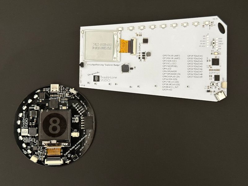
The “Explorer Badge” is a CircuitPython board with integrated features to provide an all-in-one learning device.It has been inspired by Adafruit’s Circuit Express series.The combination of the RP2040 with 8MB of Flash and a wide array of integrated hardware, makes the Explorer Badge an excellent ...

 digital tree
HackberryPi Handheld

 jade path
digital tree
HackberryPi Handheld
jade path
digital tree
HackberryPi Handheld
love it! Does the onboard wifi chip for the pi zero w support monitor mode?
digital tree
jade path
love it! Does the onboard wifi chip for the pi zero w support monitor mode?
Yes

 slate torrent
Took a very tiny (almost non-apparent) amount of inspiration from the Feather ESP32-C6 and added an LSM6DSV32X to it. It is mostly the same, apart from some slight differences. It has the same pinout, so it should be usable in the same way. Gonna be a little while before I can order the boards.

Hopefully the IMU won't be under stress. I've made a board using it before, but I think that it came under some stress which makes have some weird drift characteristics. Either it doesn't drift at all, or it drifts 100 degrees in about 10 minutes. Some drift in the heading axis is expected of aa 6-axis IMU, but that much isn't right.
The BOM cost, excluding small components like resistors, capacitors and 21% tax isn't even that high. I might also build a bord using the BNO085 some time. I've found the magnetometer to give much better performance, although it doesn't seem to be very smooth.

Also added some stuff to the bottom because 𝘧𝘢𝘯𝘤𝘺

 solemn ferry
slate torrent
Took a very tiny (almost non-apparent) amount of inspiration from the Feather ES...
solemn ferry
slate torrent
Took a very tiny (almost non-apparent) amount of inspiration from the Feather ES...
Wow, cool. Doesn't adafruit say the BNO085 has issues with ESP32 I2C though? I saw it somewhere
solemn ferry
slate torrent
Also added some stuff to the bottom because 𝘧𝘢𝘯𝘤𝘺
Love the bottom marking
slate torrent
Wow, cool. Doesn't adafruit say the
 torn fiber
Made this LED Stock Ticker with the Adafruit 64x32 LED Matrix (5mm pitch), Matrix Bonnet, and Raspberry Pi 4. I’m still working on trying to get the padding between the symbols even, but the logo sizing makes it a bit difficult. If you look closely at the monitor it shows the terminal, and it is getting the live stock prices every 5 secs and updates the symbol accordingly if there is a noticed change in the price, that is using the Finnhub API and Websocket to get live quotes. Can't wait to test it out during NYSE open, let me know what you think and if you think anything should be changed.
 high imp
Learn and see how to make some different breakout boards in KiCad 8
https://youtu.be/J3X9zgJsM18

Please visit the video sponsor : https://www.pcbway.com
Complete design walkthrough process going through the schematic and PCB design for this board.
▶ Subscribe: https://www.youtube.com/channel/UCqyPRKnXxjDJOQAXV__6yNw
Click the Bell Icon to get notifications about my future videos!
▶Refererral link:
https://pcbway.com/g/i8683S
▶Order PCB ...
dark cairn
It may be tui, but it's well made tui
Reusable sliders, selector panels, screen can lock at any point with timeout or manually.
I will make this be on par with normal smartwatches.
Albeit tui.
bitter dome
dark cairn
this makes me wanna get a t-watch s3
dark cairn
bitter dome
this makes me wanna get a t-watch s3
Also, I have a full file manager that does things already implemented.
You can even select ducky scripts to have them ran or even "type" text documents to a computer.
By the time you get it i'll have a audio playback through the file manager too.
bitter dome
wait it also got a speaker too?
dark cairn
just tx unfortunately
dark cairn
bitter dome
does it have an sd card slot too?
Nope, it's 110% full inside, no space for an led even.
dark cairn
it's a n16r8
the psram is a lot more important here as you can do things with the display and wifi
bitter dome
@dark cairn one thing im curious, what is the software programmed in?
dark cairn
bitter dome
<@614096041083404300> one thing im curious, what is the software programmed in?
CircuitPython, the port PR got merged today.
alpine token
Article I wrote about CircuitPython VS Arduino C. TL;DR: Which is better depends on the situation: https://embeddedcomputing.com/technology/open-source/development-kits/arduino-vs-circuitpython-for-microcontroller-programming Also, H/T to @warped siren who IIRC answered a question I had while working on it and is mentioned toward the end!

Embedded Computing Design
If you’re starting out in the world of microcontrollers and dev boards, you may find yourself faced with a fundamental question: Arduino or CircuitPython? Some of the same considerations will also apply to MicroPython–which you can read about here–but I’ll table that discussion to keep the scope reasonable.
warped siren
alpine token
Article I wrote about CircuitPython VS Arduino C. TL;DR: Which is better depends...
Good article! It covers the main difference for me when choosing: Do I want to try something out fast? Then CircuitPython. Do I need it to be fast? Then Arduino (or chip SDK).
Most things don't need to "be fast" in the code one writes, especially if the fast stuff is already being done (and tested!) inside the CircuitPython core (USB, audio, display compositing, keypad debouncing, encoder reading, etc etc)
dark cairn
Thy alarm screen
alpine token
warped siren
Good article! It covers the main difference for me when choosing: Do I want to t...
Thanks so much, and thanks for your help with it, both directly and indirectly!
clever stone
@alpine token - when I am planning a "product" I often choose CircuitPython because it is easy to customize and more approachable for a broader set of end users.
A simple example: I purchases a Rot13Labs "fox" - a PCB with a small transmitter module used to create a low power transmission which user need to find using RF listening equipment.
Before a consumer can use the "fox" they must edit the code (to change just one variable) to use their FCC callsign.
The product came with an implementation using the Arduino framework and easy-to-follow instructions. Even still, the consumer must setup their Arduino tools and configure as you describe.
I ported their code to CircuitPython. Now a user only needs a text editor to change the one variable and they are done.
When performance is key, my language is C 🤩
alpine token
clever stone
<@354418635584045056> - when I am planning a "product" I often choose CircuitPyt...
Good point for sure! Ha, nice little tagline - you come up with that?
clever stone
Yeah. I sometimes get lucky with words.
Here is the rot13labs fox hunt badge (I have no involvement in the hardware).

I ported their Arduino code to CircuitPython.
https://gitlab.com/bradanlane_cp/foxhunt
 ruby ocean
clever stone
<@354418635584045056> - when I am planning a "product" I often choose CircuitPyt...
ruby ocean
clever stone
<@354418635584045056> - when I am planning a "product" I often choose CircuitPyt...
I ported their code to CircuitPython. Now a user only needs a text editor to change the one variable and they are done.
With circuitpython, that can be put in settings.toml, to the user does not even need to touch the code.
clever stone
@ruby ocean - true. Either way they need to edit one file to change one setting.
dark cairn
Stopwatch app, laps recording included.
works up to 999 days

I'll get exporting laps to txt in /home done in a later iteration.
I'll also implement a lap difference graph on the last 2 lines later on.
By the time i'm done this will be the most professional clock.
sand grotto
dark cairn
By the time i'm done this will be the most professional clock.
Casio fans gonna bite your hand off for one 😉
dark cairn
Timer app
Just cause it's tui doesn't mean it can't be fancy
The changes in the hourglass are 100 lines of if-elses that apply the differences of each state.
grave nacelle
I made a visual USB gamepad tester thing for Feather TFT and the MAX3421E USB Host FeatherWing. The code uses adafruit_imageloader, a BMP spritesheet, and displayio.TileGrid to show animated gamepad buttons on the LCD that change color when you press buttons on the actual gamepad: https://youtu.be/pUZS2N6Ij_4?si=JMHMXlNshjJtsDyk

This shows an Adafruit ESP32-S3 TFT Feather running my CircuitPython code to read input from a USB gamepad and visualize the button presses on the LCD. The visualizer uses a BMP sprite sheet file with a displayio.TileGrid.
There's also a playground guide about it here: https://adafruit-playground.com/u/SamBlenny/pages/feather-tft-gamepad-tester-with-sprites
The gamepad.py file has an XInput gamepad driver that people might be able to reuse for other projects. But, so far I haven't managed to get the driver working with my 8BitDo USB Wireless Adapter 2. If I could get that to work, then the gamepad driver might be pretty widely usable with various wireless gamepads, which would be nice. So far, that doesn't work though.
kind burrow
Hi all. I tried out and did a fair amount of Python/Arduino coding with PyFirmata few months back - the link is
https://roboticsbackend.com/control-arduino-with-python-and-pyfirmata-from-raspberry-pi/
It was in a CircuitPython weekly newsletter from Adafruit a few months ago.
Anyway, still trying to keep up my chops in Arduino, so here's the latest project.
I have an Ada FT232H with an Airlift breakout running Python code on the PC. It downloads JSON and saves it to my disk, then runs a Python script to import this file, and sequentially pass data thru PyFirmata (installed on both the PC, and the receiving Arduino boards) thru the COM port.
This display is Ada ST7789 EYESPI hooked up to an ancient BareBones board with ATMega168 chip.
The weather data is from api.open-meteo.com
The pic is live weather data in Texas - it's HOT.
P.S. I tried this same code on a QtPy SAMD21, but the firmata.h file does not have that board definition, so no dice. And I don't think anybody's gonna update the file...
I have several OLD Ard boards running Pyfirmata stuff - it's pretty cool to create nice Python code on the PC, and pass data to them. At least they're not obsolete "quite" yet. The Arduino code is very simple, since all does is get a callback from Firmata, get the string, and display it on whatever.


Control your Arduino board directly from your Raspberry Pi (or computer) with pyFirmata, using only Python code. Complete tutorial with code examples.
north mural
kind burrow
Hi all. I tried out and did a fair amount of Python/Arduino coding with PyFirmat...
I've done something similar with Circuit Python. One advantage of Circuit Python is you can have Python download a CSV or JSON file directly to the CIRCUITPY drive because it's a USB mass storage device. I wouldn't even know where to begin to do that with Arduino. Well done!
lean elbow
I built a Bluetooth adapter for plugging in a Wii nunchuck. While it could be used to control any number of things, I'm using it right now to control these LED glasses.


 jovial pilot
I recently completed a tactile Augmentative Alternative Communication device for a largely nonverbal client. Uses the RP2040 prop-maker, CircuitPython, and 160 snap-dome buttons to play pre-recorded phrases. Folds away for a bit of portability.
[Video shows a person opening the Augmentative Alternative Communication (AAC) device by lifting a velcro strap, revealing the grid of brightly coloured icons. When closed the AAC is slightly wider than a sheet of paper. When open it almost doubles in width. The camera zooms in as the person presses an icon of a speaker with the word "DOWN". The AAC then plays the phrase "Please turn the volume down"]

 dark cairn
Snake game soon on T-Watch-S3

I "could" have used a bmp sprite sheet file.
But I'm me, so 150 lines of setting colors on a bitmap during init.
Now it's undebuggable.
 lucid sigil
Mini MIDI player on M5AtomS3 + M5Synth unit
https://www.youtube.com/watch?v=JEpDJCvkeEI
https://github.com/konstantint/M5MidiPlayer


GitHub
CircuitPython MIDI player app for M5 AtomS3 + Synth Unit - konstantint/M5MidiPlayer
stark latch
Working on a 3D-printed key mechanism that's compatible with MX-style keycaps. Here's and early test.
https://www.youtube.com/watch?v=y0qTy7bDPgk

This is a 3D-printed key switch that's compatible with MX-type keycaps. In this case, I printed my own keycap but pretty much any compatible one will do.
The entire mechanism is printed in PLA, except for the copper foil.
sharp comet
I'm tinkering with the Circuitpython Web IDE with the aim of adding support for serial plotter similar to Mu. Starting to see some data getting plotted for the first time is exciting 🎉
 sudden sail
For some reason, (and I won't assert that it is a good one) I decided to build a battery powered hand held recursive DNS server. It has RGB lights, a convenient hand grip, and an IT Crowd reference. Raspberry Pi Zero with Pi-Hole and Unbound DNS in a 3D printed case I designed.


 neat cloud
dark cairn
Snake game soon on T-Watch-S3
neat cloud
dark cairn
Snake game soon on T-Watch-S3
I don't suppose you have any source you could share? I'm having a heck of a time bringing up the ST7789 on mine.
dark cairn
neat cloud
I don't suppose you have any source you could share? I'm having a heck of a time...
Are you on CircuitPython or are you trying to do it in C?
The init sequence and pins are available in the CircuitPython source.
https://github.com/adafruit/circuitpython/blob/main/ports/espressif/boards/lilygo_twatch_s3/board.c
neat cloud
dark cairn
Are you on CircuitPython or are you trying to do it in C?
The init sequence and ...
In CP
sonic fractal
my latest board design, kinda sligtly maybe close to one year after my first design

here is my first one

 subtle fox
nice!!
 sonic fractal
 steep remnant
My latest. Fig Pi boards, color silkscreen.
steep remnant
My latest. Fig Pi boards, color silkscreen.
Oooh that is GOOD! how much extra does the color silkscreen coat? I wanna try it someday
lean elbow
Wrote some firmware for the LED Glasses driver board to go along with the Wii Nunchuck BLE adapter I built a couple of weeks ago. I wrote about it at https://adafruit-playground.com/u/squid_jpg/pages/sparkle-specs-firmware-for-adafruit-led-glasses-driver (PlatformIO Arduino source code is also available on my github, linked in the write-up)

Worth mentioning that the firmware also works without the nunchuck, and works with the Bluefruit Connect app!
exotic sierra
The iCE5LP4K FPGA feather I developed is now supported in IceStudio and APIO

Also RPGA Feather as well
lean elbow
lean elbow
Wrote some firmware for the LED Glasses driver board to go along with the Wii Nu...
Quick update: I finally figured out how to convert the compiled bin files for the firmware into UF2 files, so if you want to try out the Sparkle Specs firmware (and/or the BLE nunchuck adapter) without having to deal with PlatformIO, it's super easy. Both guides are updated!
 thin turret

 void spoke
🚀 Excited to introduce PowerTiger! A powerful, open-source energy monitoring solution built around the RPi Pico W. Perfect for tracking power consumption in real-time for 16 terminals.
GitHub
Home power monitoring system - Monitoring energy consumption with better granularity - codetiger/PowerTiger
sand grotto
void spoke
🚀 Excited to introduce PowerTiger! A powerful, open-source energy monitoring so...
Nice one! You might benefit from adding a StemmaQT / qwiic connector for future i2c expansion (other sensors or display etc)
 proud spindle
That is very cool
void spoke
Sure, am working on the next version. That sounds great option to add, for solder-less users
Almost all of my knowledge came from Adafruit’s documents and repositories. Can’t express how much am thankful to Adafruit.
 sacred timber
I just received my Adafruit CH334F 4 port USB hub breakout and am starting to replace the bulky USB cables on my robot. The existing Zero4U hub (lower right, with blue lights) will be replaced by the CH334F (lower center, with green lights). I've finished one: the connection between the CH334F and a Pimoroni Tiny FX (upper left) that I'm using for lighting. This is looking down on the robot from above.

 rose rampart
https://github.com/Mrgithub93/CharLCD_Draw
I made a simple drawing script for custom characters on LCD screens
GitHub
custom 8 characters drawing for LCD displays. Contribute to Mrgithub93/CharLCD_Draw development by creating an account on GitHub.
 glad crescent
I don't know how many people are using Bluesky but it seems to still be a bit small when it comes to tech projects or open source stuff. I developed a custom feed over the weekend that aggregates personal projects across the network, feel free to check it out! Anything with tags like #opensource, #raspberrypi, etc. should get caught by it, though I'm still working out kinks with the algorithm lol. Check it out and let me know what you think!
https://bsky.app/profile/idreesinc.com/feed/tech-vibes
steep remnant
sonic fractal
Oooh that is GOOD! how much extra does the color silkscreen coat? I wanna try it...
As of right now - I think it's cheaper. It does require ENIG finish and a couple other things, but I was using that anyway.
lean elbow
Remix of a cool LED noodle Triforce. Made the body volume big enough for a QT Py mount, and used a QT Py to make the LED noodle pulse.
(original print can be found here https://www.printables.com/model/372674-triforce-led-noodle-light)

Printables.com
Triforce light made with LED noodle (https://www.adafruit.com/product/5503), printed on Prusa i3 mk3. | Download free 3D printable STL models
 fleet dragon
How about industrial-quality controller that runs Circuitpython? This one is based off Feather M4 CAN, extended with industrial DIO and analog inputs. Protected against almost everything (ESD, overcurent, short circuit etc) . Check it out!
https://github.com/rox-automation/rox-icu

GitHub
Software and documentation for ROX Integrated Control Unit - rox-automation/rox-icu
fleet dragon
sacred timber
I just received my Adafruit CH334F 4 port USB hub breakout and am starting to re...
😱 omg jumper wires
 upper sage
I've made a graphics editor and code builder for U8g2 and AdafruitGFX
I’ve been working on this project more than a year now but I was too humble to just post about it everywhere around. I still feel nervous writing this...
https://lopaka.app/ is my pixel graphics and interface editor for projects with OLED/TFT/LCD displays. It produces ready to use code based on popular graphics libraries
The source code is open and it is free to use: https://github.com/sbrin/lopaka
Right now in Lopaka you can:
- draw basic shapes
- write text in different fonts
- insert images
- generate ready-made code for u8g2, AdafruitGFX, TFT_eSPI
- convert images to XBMP
Anyway I believe that small tool would be very useful for our community.
 tired shard
Just a tell and no show, but I've had these two fans in my house for a long time with no remotes. Decided to just make every IR remote turn them on and off, a capacitor on the IR signal line and and a diode from there to the button makes it work! Life changing honestly. (also ripped out the piezo buzzer 🙌 )
void spoke
tired shard
Just a tell and no show, but I've had these two fans in my house for a long time...
How do you differentiate noise and signal? I mean doesn’t a bright sun light produce IR and that switches the device
sacred timber
void spoke
How do you differentiate noise and signal? I mean doesn’t a bright sun light pro...
It's not the presence of infrared light, it's the presence of infrared light pulsed at a very specific frequency.
void spoke
sacred timber
It's not the presence of infrared light, it's the presence of infrared light pul...
In that case how will it work with every IR remote as mentioned in the original post? That’s what am wondering, coz every IR remote has a different pattern of IR pulse right? Plz correct me if my understanding isn’t correct
sacred timber
void spoke
In that case how will it work with every IR remote as mentioned in the original ...
Yes, each manufacturer can use a different frequency and protocol, or they use something like Philips RC-5 protocol, which has a code that's passed over the beam called a System Number to differentiate different devices, so that your Yamaha stereo and your Samsung TV remotes don't fight with each other. But you can also buy universal remotes that can send messages to any device, you just have to tell the remote which device you are mimicking.
tired shard
void spoke
In that case how will it work with every IR remote as mentioned in the original ...
It works because when the IR receiver pulses low for the fist bit in the signal the capacitor makes it so that it can't immediately recover, this low state is what triggers the button. So its only relying on the fist pulse which can be provided by most if not all ir remotes. (at least I think that's why it works)
sacred timber
tired shard
It works because when the IR receiver pulses low for the fist bit in the signal ...
I'm not sure if I'm understanding you correctly, but not all protocols use a low start bit, but it sounds like your circuit would simply react to the first low bit, even if it wasn't actually the first bit.
tired shard
Exactly the first low pulse is held low long enough to be interpreted as a button press
sacred timber
You might get false triggering from other remotes since this is somewhat haphazard, but it's not like there's a whole lot of remotes in your house that you're aiming at your fans I'm guessing.
tired shard
Yeah if put directly beside the tv it'd be fairly annoying but thats just not the case for me. The nice thing is the way the fan is made you do have to actually aim the remote for it to work. When not in the enclosure though you can turn it on and off with the ir coming out of the flame from a lighter so that's fun, maybe the sun would trigger it but they're fairly shielded, does window glass block ir?
sacred timber
Sounds like an interesting way to take advantage of what's kinda a hole in the system... and play time too!
sacred timber
fleet dragon
😱 omg jumper wires
I'm curious: what would you do?
I mean, even NASA/JPL uses jumper wires...
 tired shard
sacred timber
Sounds like an interesting way to take advantage of what's kinda a hole in the s...
tired shard
sacred timber
Sounds like an interesting way to take advantage of what's kinda a hole in the s...
lol exactly
void spoke
tired shard
Exactly the first low pulse is held low long enough to be interpreted as a butto...
Interesting
would love to hear about your experience after a few weeks.
tired shard
It's been about a week. No complaints here.
cunning lava
coding a tiny boulderdash game
 tired shard
void spoke
Interesting
tired shard
void spoke
Interesting
too lazy to pull apart the fan but here's what a bare bones example would look like (the higher the capacitance the longer the low state)
 fleet dragon
sacred timber
I mean, even NASA/JPL uses jumper wires...
fleet dragon
sacred timber
I mean, even NASA/JPL uses jumper wires...
For a "central" arhitecture (good for small robots) I'd use something like Pimoroni Yukon . For a "decentral" architecture multiple local nodes connected by a CAN bus would be great (like in automotive).
sacred timber
fleet dragon
For a "central" arhitecture (good for small robots) I'd use something like Pimor...
I'd actually like to use Yukon but I want a higher-level controller like a Raspberry Pi, and the Yukon doesn't easily lend itself to being a sub-controller, it's kinda meant to be the master. If I could shove my entire robot OS into MicroPython that might be the case, or if I started on a different, simpler robot then sure, I'd likely consider Yukon as my entire system. It looks good.
 pseudo tree
sacred timber
I just received my Adafruit CH334F 4 port USB hub breakout and am starting to re...
pseudo tree
sacred timber
I just received my Adafruit CH334F 4 port USB hub breakout and am starting to re...
what in tarnation... I love it.
bitter dome
i hope this channel also cover libraries, here's an irc library i just wrote for esp-idf projects: https://github.com/Danct12/esp-irc
GitHub
A small, easy to use IRC library for ESP-IDF. Contribute to Danct12/esp-irc development by creating an account on GitHub.
sonic fractal
sacred timber
I just received my Adafruit CH334F 4 port USB hub breakout and am starting to re...
This looks impressive, and also looks like electronic spaghetti bolognese.
May i ask, where is the main core of the robot, like which one of those boards holds the MCU or SBC that runs it?
sonic fractal
upper sage
I've made a graphics editor and code builder for U8g2 and AdafruitGFX
I’ve been ...
Dude you are a legend! Ive been using lopaka for some of my projects and i love it
sacred timber
sonic fractal
This looks impressive, and also looks like electronic spaghetti bolognese.
May i...
Sure. That photo obviously was rather confusing. It's spaghetti in the sense that I've got wire harnesses running all over the place, but they're all just standard 0.1" Dupont connectors going from board to board, so it's not actually so confusing if you know what the devices are.
This photo shows the robot a bit better. There are three levels of 3mm black Delrin plastic, the lowest is the battery mount (you can see the Makita 18V battery hanging underneath) and an area for the mess of wires coming from the motors, motor encoders and some of the motor armature sensors to be hidden. The next level has the voltage regulator, motor and servo controllers. This is all hidden behind that aluminum control panel with the toggle switches and knobs, open on the other side. The top plate has a Raspberry Pi 4 at the back, several ESP32s for various things, an I2S sound board, and there's room for what will eventually be a cluster of three STM32 Pyboards that will be used when I get to "phase 3" with all six motors and the triple-rocker suspension.
The front of the robot has a clear polycarbonate bumper and a bunch of sensors. The two masts have IMUs at the top, with a shorter mast for a GPS unit.

As Jev mentioned in the "I'd actually like to use Yukon" thread, the idea with the Pyboard cluster is that I'll eventually be pushing the RT tasks off to the Pyboards and leaving the Pi to do the higher-level planning. The OS is in Python and is a Behaviour Based System. A single Pyboard can manage a pair of quadrature motor encoders natively in MicroPython, hence the trio of boards.
I forgot to mention that there's also a Raspberry Pi Zero 2 W mounted near the front with a standard Pi camera that streams HD video for telerobotics use, and an OAK-D Lite smart camera that's mounted but currently not (yet) used. I'll be using it to get pixel-level distance sensing off its stereo cameras.
sonic fractal
sacred timber
As Jev mentioned in the "I'd actually like to use Yukon" thread, the idea with t...
I am quite impressed, crazy how it has like every sensor to register everything happening around it
sacred timber
sonic fractal
I am quite impressed, crazy how it has like every sensor to register everything ...
The basic idea is relatively simple. It's a Behaviour-Based System (a bit like an insect's mind), so everything is a Behaviour. Each sensor has a purpose, and its output is used to create a Behaviour. For example, there are digital (on or off) IR bumpers on all the wheel armatures that simply cause the robot to stop. There are also a pair of analog (variable value) IR sensors aiming outward at an angle from the front - you can see the small green board just behind the polycarbonate bumper. Working together they provide a distance measurement left and right, and together create a behaviour that modifies the left and right motor velocities to speed up or slow down depending on the distance value from each sensor. So if the right sensor senses an obstacle closer than the left sensor that makes the robot move more to the left, away from the obstacle.
The IMU has an accelerometer, gyrometer and magnetometer (each contributing 3 degrees of freedom (DoF) so it's a 9 DoF IMU). If the robot tilts too much in one direction it just stops in place currently and screams, but it could also have a different reaction, like maybe backing up. I've got a "Move North" directive that uses the magnetometer to generally choose to go north when the robot can, whilst avoiding obstacles.
I've also got a VL53L5CX on the front that returns an 8x8 grid of distances up to 4m with an accuracy of 1cm. Pretty amazing sensor, about the size of a grain of rice. I take that grid and normalise the vertical values (since ground-based robots dont' usually care too much about the vertical), run the whole thing through a simple algorithm, and voila! I get a pretty good indication of where a doorway is: anywhere that is open vertically and has a distance greater than the sensor's limits. With that, I again alter the left and right motors (adding a lambda to each) to tend to steer the robot through the doorway.
 floral prawn
My first experience coding with CircuitPython

In this video we shall we shall see how to program the MAKER UNO RP2040 for the first time. We will be using the Thonny compiler for programming. As for the code, we will be using the example code provided in the Cytron official tutorial site.
Below is the link for the tutorial:
https://my.cytron.io/tutorial/getting-started-guide-with-maker-uno...
thin turret
I made a neopixel tester/counter out of parts on hand. The first 3 leds are RGB so you can tell if the string has a different color order. The buttons are +100 +10 +1 / -1 -10 -100 and move the white pixel. I work with a rock opera theater company and there are a lot of props that have neopixels in them built by volunteers and this is going to help so much with debugging and testing with out having to break out the strandtest and keep re-compiling with different strand lengths or hands on counting pixels to see where an element begins
 sacred timber
I've just updated my I2CSlave code for the RP2040. It provides the ability to send up to 32 ASCII characters to an RP2040 slave device and return a single byte status code. There's also an I2CDriver class that subclasses I2CSlave, using the message content (e.g., "set dark_orange") to set the NeoPixel on an Itsy Bitsy RP2040. Anyone could similarly do a subclass for their own purposes. I plan to extend I2CSlave to also set the on/off state of the six LED channels on a Pimoroni Tiny FX.
https://github.com/ifurusato/mros/tree/main/itsybitsy-rp2040

GitHub
Operating System for the MR01 Mars Rover. Contribute to ifurusato/mros development by creating an account on GitHub.
grave nacelle
I made a clock thing for Feather TFT.
Playground guide: https://adafruit-playground.com/u/SamBlenny/pages/feather-tft-clock-with-gamepad-input
Code: https://github.com/samblenny/feather-tft-clock
 vernal vigil
My latest Eurorack module prototype, using a Daisy Seed

 untold sable
grave nacelle
I made a clock thing for Feather TFT.
Playground guide: https://adafruit-playgro...
untold sable
grave nacelle
I made a clock thing for Feather TFT.
Playground guide: https://adafruit-playgro...
@grave nacelle Interesting in that I liked the font for the 7-seg clock, but if I am reading your code right, that is not a font but instead a bunch sprites of each bar displaying the time?
untold sable
vernal vigil
My latest Eurorack module prototype, using a Daisy Seed
@vernal vigil a couple more prototype boards in the mix and I think you're there. 😆
last bronze
stolen from uni, asked if it was stocked officially and the storage manager literally shoved it into my hand ✨😍

They look brand new, it's a whole controller board pulled out of a Zopan PFL-20 frequency counter
grave nacelle
untold sable
<@1220648290941669377> Interesting in that I liked the font for the 7-seg clock,...
that depends on how narrowly you define the term "font"... you're right that it uses displayio.TileGrid sprites to display glyphs for letters rather than using CircuitPython's text label mechanism (which, I think, probably uses font files).
 obsidian wind
last bronze
stolen from uni, asked if it was stocked officially and the storage manager lite...
obsidian wind
last bronze
stolen from uni, asked if it was stocked officially and the storage manager lite...
I love it when the lab manager tells us to just get rid of his old junk so he doesn't have to
slate torrent
slate torrent
Took a very tiny (almost non-apparent) amount of inspiration from the Feather ES...
Just built it (still missing an LDO for the IMU because I forgot to order it, but I can wire it up to 3.3V as well so gonna try that tomorrow).
First time relfowing a PCB for me. Used the MHP50 from miniware which so far seems absolutely amazing, although I have nothing to compare it to.
 grave nacelle
@terse totem I got curious about your mention of making a keyscan tester thing and wanted to see if I could read raw HID reports from CircuitPython. Turns out it works pretty well, subject to some minor timeout tuning. Anyhow, I made this thing. Thought I'd send you a link in case there's any code that would be of use to you: https://github.com/samblenny/pumpkin-numpad-tester
there's also a video demo at https://www.youtube.com/watch?v=wvavzqcXkAI
I haven't written up a Plaground guide though... didn't want to get out ahead of whatever you end up doing.

GitHub
work in progress (alpha). Contribute to samblenny/pumpkin-numpad-tester development by creating an account on GitHub.

It's almost Fall, so here's a pumpkin themed numeric keypad tester. The display uses CircuitPython displayio TileGrid sprites to indicate key presses. Details of the USB HID reports get logged to the serial console. The hardware is an ESP32-S3 Feather TFT, a MAX3421E USB Host FeatherWing, and a Perixx USB numeric kepad.
 analog nymph
I just created a Python script to use a Feeltech function generator and Hantek oscilloscope to sweep a filter and create a bode plot. The script is published here: https://github.com/jonw0224/bodeplot

GitHub
Utilizes a FeelTech FY3225S function generator and a Hantek 6022 osilloscope to sweep a filter from 10 Hz to 2.5 MHz and create a bode frequency response plot - GitHub - jonw0224/bodeplot: Utilize...
bitter dome
added TLS support to my esp32 (esp-idf) irc library

since it uses esp-tls library, it should be compatible with wolfssl as long you provide a tls certificate by yourself as it does not support the CA bundle library from esp-idf.
wolfssl is untested but i'd suggest to avoid it for a commercial product unless you're willing to pay for a license
weary night
I just got a tip to join the live show and tell show with the Walter module that we have launched. This because I actually want to get Walter distributed through Adafruit and that would be the best way to get in touch with the right person. Walter is a Pycom GPy replacement and upgrade. It is a multi-radio cellular IoT module based on the ESP32-S3 and the Sequans Monarch 2, there is WiFi, BLE, LTE-M, NB-IoT and GPS/GLONASS. The module is fully certified (CE, FCC, UKCA, IC, RCM) which means that you can incorporate it into commercial designs without the need to go through very expensive certification, basic EMC/spurious emissions testing is enough.
From a software perspective me and my team are fully committed to the open source approach and to give choice to developers. On github we have published our libraries for Arduino, ESP-IDF and Micropython. We have contributed the Sequans modem drivers to the Zephyr project and also added Walter as a board. We are also working together with IoT platforms such as Golioth, Datacake, BlueCherry, ...
For now we made some tracking demo's and we have a Walter Feels board which does remote sensing, I also created an fine dust sensor, ... everything is on https://www.quickspot.io. Now I would be keen to learn how to best present this on the Show and Tell show. Any cellular IoT projects that you have in mind (and are buildable in a few hours) would be nice to hear.

Walter IoT module
Meet Walter, the only module which combines WiFi, Bluetooth, NB-IoT, LTE-M and GNSS in a single super small and easy to use package. You can program walter using Arduino, Micropython, the Espressif IDF and more. CE and FCC certification is currently pending which makes this a truly unique product.
 lapis kestrel

 stiff crystal
Checking in for Show/Tell, have not been able to for a while. Just watching tonight!
 dusk zinc
Not finished yet, but this is a project I'm doing for a family member to detect when the mailbox is opened. I didn't want any cables or devices near the mailbox opening, so this uses light sensors (two different I2C lux sensors, a phototransistor, and a PIR ...for redundancy(!), and for good response at full range).
Inside the metal mailbox is the sensor box (left). It's cabled through to an outside radio box (right) immediately behind. The radio box has the MCU, LoRa board (too far for wifi), and power from 12VAC.
LoRa messages are sent to a remote unit in the house: when the MCU is restarted, when light is detected inside the mailbox, when light is detected in the radio box (indicating possible tampering), and hourly. The messages will be retried with increasing random backoff, and there's a CRC and acknowledgements from the house unit.
The house unit has a TFT display, 3W I2S amplifier with speaker, and a NeoKey. It spends most of its time listening for a message. When the mailbox has been opened, it will play an MP3 file (several times over a period of time), and light up the NeoKey in case the sound isn't heard. Pressing the NeoKey will stop the sound (there's also a switch to turn off the sound completely). May add SMS or email notifications.
Because it's inconvenient to access and change the software in the radio box, each acknowledgement message from the house unit contains current datetime (all messages are timestamped), and configuration parameters that may get updated from time to time.


 scenic siren
dusk zinc
Not finished yet, but this is a project I'm doing for a family member to detect ...
scenic siren
dusk zinc
Not finished yet, but this is a project I'm doing for a family member to detect ...
This is excellent! I had considered using a light sensor for mine, but ultimately went with the reed switch. I wasn't sure if a light sensor would work. Good to know it does!
 sly bane
wanted to give a quick shout-out to people here for helping me with this design at a few points - this is a pretty basic circuit (astable 555 timer with adjustable on/off cycle gated by an analog sensor and switching a power relay) that I'm going to be using to control a solenoid valve to water my mushrooms based on soil moisture, but it should be applicable to any switchable device and any sensor with an analog voltage output

don't ask about the empty LED holes, I definitely didn't burn out all my LEDs during prototyping
 supple mortar
I like the new packing materials !

 cursive oak
https://learn.adafruit.com/adafruit-dvi-sock-for-pico/circuitpython#hello-world-dvi-output-example-3170966 works without any changes to the example code, on the Raspberry Pi Pico 2!
 fervent finch
Little ESP32 based display for next arriving bus and streetcar in New Orleans is more or less done. Debating whether to try a diff color for the 3d printed LED covers.

 lean elbow
fervent finch
Little ESP32 based display for next arriving bus and streetcar in New Orleans is...
lean elbow
fervent finch
Little ESP32 based display for next arriving bus and streetcar in New Orleans is...
Another thing you might consider is using filter gels like these cut-to-size for your seven segment displays https://www.amazon.com/gp/product/B0CN2T59V7. They do a pretty good job of masking out the unlit segments while making the lit segments really pop.
fervent finch
lean elbow
Another thing you might consider is using filter gels like these cut-to-size for...
Interesting! I might give these a shot
fervent finch
lean elbow
Another thing you might consider is using filter gels like these cut-to-size for...
Remembered I had some gel samples around! Thanks for the suggestion!
 lean elbow
fervent finch
Remembered I had some gel samples around! Thanks for the suggestion!
lean elbow
fervent finch
Remembered I had some gel samples around! Thanks for the suggestion!
Oh that looks really nice! 😄
fervent finch
lean elbow
Oh that looks really nice! 😄
Thank you! I agree it looks better than the 3d printed covers. Was having issues getting those to lie flush
fervent finch
And now: making a capacitative switch for the next one.
lean elbow
I know I know, everyone's built some version of a "Doomsday Messenger" at this point. Still, here's my own take on them, using Solder Party's Keyboard Featherwing and featuring a UI written using LVGL.
https://adafruit-playground.com/u/squid_jpg/pages/keyboard-featherwing-messenger-powered-by-lvgl
 cedar trellis
lean elbow
I know I know, everyone's built some version of a "Doomsday Messenger" at this p...
cedar trellis
lean elbow
I know I know, everyone's built some version of a "Doomsday Messenger" at this p...
I would really love the project ... if I weren't so jelly that you got not one, but TWO keyboard featherwings! 😆
I missed out on those 😭
lean elbow
cedar trellis
I would really love the project ... if I weren't so jelly that you got not one, ...
They are so cool. I've heard rumors that a new version may be forthcoming...
Also at the end of my playground I wrote a little about what could be a nice alternative (The LILYGO T-Deck). Once I'm gainfully employed again I'll probably grab a couple and port the firmware to them.
cedar trellis
lean elbow
They are *so* cool. I've heard rumors that a new version may be forthcoming...
...
Oh, nice, I'll check it out, thanks!
Also, awesome project!
lean elbow
Thank you! 😄
grave nacelle
I made a CircuitPython game about pumpkins and skeletons for Feather TFT with USB gamepad controls. Playground guide which includes code, an embedded gameplay video, etc is at https://adafruit-playground.com/u/SamBlenny/pages/pumpkins-vs-skeletons-game-for-circuitpython


 errant pasture
Finished implementing audiodelays.Echo in a synthesizer project I've been working on. Here's a video demonstration if anyone is interested in hearing what it sounds like in practice. https://youtu.be/OMHBoUTUblk @median spoke @warped siren

This utilizes the latest build from this pull request: https://github.com/gamblor21/circuitpython/pull/1
For more information, follow the main pull request here: https://github.com/adafruit/circuitpython/pull/9640
Thanks to Mark (@gamblor21) for laying the foundation for the new audio effects system!
clever stone
"Code" can be boring and not cool so I created an animation to explain how I wrote Python to automate the machine files for pick-and-place machines ...
 stiff coral
Behold…the Fartsichord…built from scratch it is a functional Fotoplayer style device.


The keys play the fart noises, the gold buttons play cartoon sound effects, the monkey can play the cymbal when you flick the level below him, there is a clown horn, trail whistle and diner bell. The screen to the right is the mp3 player which plays the music as I sync the sfx and farts with it
scarlet pelican
stiff coral
Behold…the Fartsichord…built from scratch it is a functional Fotoplayer style de...
That may be the coolest thing I have ever seen
In other news, we used some Adafruit USB-to-TTL serial cables to get a terminal connection to a Synertek SYM-1 from 1978. It didn't work at first -- using the scope we finally figured out the SYM-1 used inverted logic (so 0 V represented a digital "1"), so we used a 74LS04 inverter and it worked! https://youtu.be/Q0vPR5ka12A

The SYM-1 TTL serial interface uses a convention that's inverted relative to all the modern USB-to-Serial interface cables I have, so we used a 74LS04 inverter chip. The negative logic doesn't seem to be mentioned the manual; we discovered the convention via an oscilloscope after realizing that at some bauds rates the SYM-1 thought we were trans...
 weak lodge


Fun project to put together. Would recommend painting the numbers for ease of reading.
gray inlet
I got a couple of my pieces accepted to an art show for trans and neurodiverse artists!
The piece on the right is a custom circuit board I made in KiCad, with some through-hole NeoPixels and an ATtiny85 microcontroller.
The piece on the left contains a couple of Adafruit products: there are eight pink nOOds (#5510) and a Qi wireless receiver (#1901). The jar sits on a wireless charging pad, so I didn't need to make any openings in the jar to get the power in.

 distant frost
I have recently been fantasizing about sitting in the shade of a solar array in the desert, drinking a glass of ice water made with the solar power.
This is a picture of my first step in that direction. It is a desiccant wheel dehumidifier in the west Texas desert. I have instrumented it with the following Adafruit parts:
FeatherS2 (the brain)
Adalogger featherwing(time and storage)
HDC3021 Humidity and temperature sensors (input and output of humidifier)
NAU7802 strain gauge interface (to weigh the water produced)
various Stemma cables.
It produces a reasonable amount of water (>300 ml per hour) at 25C 25%RH which is very encouraging.
Next step: figure out its performance limits (humidity and temperature) and get it running from solar power!
 sacred timber
distant frost
I have recently been fantasizing about sitting in the shade of a solar array in ...
sacred timber
distant frost
I have recently been fantasizing about sitting in the shade of a solar array in ...
Interesting project! Would wrapping the dehumidifier in a good layer of insulation improve the performance?
distant frost
I am not sure if insulation would improve its performance. This is a big learning experience.
sacred timber
distant frost
I am not sure if insulation would improve its performance. This is a big learni...
I like that you're willing to try something that's clearly an experiment, with no guarantee of success. 300ml/hr of water isn't a bad start, that's over 7 liters per day, enough for one or two people to survive. 👍
sacred timber
distant frost
I am not sure if insulation would improve its performance. This is a big learni...
I'm curious: how does the water taste?
distant frost
It tastes like distilled water, though my wife doesn't want me to drink it until I have had it tested like it was well water from a new well.
sacred timber
distant frost
It tastes like distilled water, though my wife doesn't want me to drink it until...
Your wife is probably right as microbes and other things can live in that water. When I was traveling in India I had a fancy water purifier, which would remove pretty much anything that might be living in the water. You can get them at any camping store.
lucid bloom
I made a parking sensor with a feather, neopixel wing, printed case and VL53L4CX. I'm using esphome/home assistant, I still have to wait a bit before I can install it but everything seems to be working. Green -> Yellow -> Red -> flashing Red when in the zone -> flashing Blue is too far. It's only going to light up when the door is open and I'm connected via Bluetooth to my vehicle. I didn't hardcode anything related to distances I used helpers to set it all up with templates so I can easily change parameters from the UI. I'll hopefully install it along with my ratgdo next week.
 lucid bloom
I did make the mistake of using qt and not attaching the xshut pin which meant that after I ota updated or reboot the sensor would be in a failed state and this was occurring as I was trying to write the component. The sensor would only work if I power cycled it, eventually got it sorted out by soldering a small wire from a1 to xshut.
 feral orchid
Extremely bad crude FM transmitter on a Pico that uses the third harmonic and some pio mixing to modulate
lean elbow
Built another fun project by the Ruiz Brothers! This time the Tri-Rod from the new Zelda game. Had to slightly scale down the rod part on the z-axis to fit my build volume but everything worked out alright! Also using the little pebble-style fairy Neopixels cuz I didn't have any of the double-sided ones.
 ashen iron
Designing a UPS board for use with RPi Zero/ RPi (with not too much USB devices attached):

Headline features:
- Up to 18 V, 3 A input
- Adjustable solar panel MPP voltage from firmware
- Up to 3 A charging (adjustable from firmware)
- LiPo/Li-Ion/LIFePo4 support (Up to 65 Ah capacity)
- On-board battery fuel gauge
- 5 V, 2.5 A output
- Battery temperature sensing + battery charging current reduction/cutoff based on temperature
- On board microcontroller for more functions (scheduled wake/shutdown, RTC function, voltage/current monitoring, power control etc.)
- Underslung on Pi
ashen iron
ashen iron
Designing a UPS board for use with RPi Zero/ RPi (with not too much USB devices...
Written more about it in Hackaday: https://hackaday.io/project/198538-powerups

Design of a smart UPS (uninterruptable power supply) for the Raspberry Pi that supports solar power input and 1S lithium-ion battery (LiPo/Li-Ion/LiFePo4).
 granite sentinel
Howdy folks!! I levelled up a costume of mine with some Adafruit 8x8 matrix(es?) and 5mm UV LEDs to make the teeth "glow". The beginner guides and Arduino sketches were incredibly helpful on the Adafruit site!! My programming skills for Arduino were not sufficient, so I worked with chatGPT to get the code working for the eyes 🙂 Happy to share the code (if that's ok) and resources for making the bitmaps if anyone else is looking to get something up and running! Eyes have a random timer for the blink and use a thumbstick to control where the eyes "look". (Instagram link shows the costume in motion)
https://www.instagram.com/reel/DBZIBxnvV8t/?igsh=Mm16NjRoeDl0czF0
 lean elbow
Whoa that is awesome 😮
granite sentinel
Thank you!!
errant pasture
Just figured out how to get analog input looped back out through I2S. Got guitar input successfully working with a simple preamp! https://gist.github.com/dcooperdalrymple/4f00bf3e7131093cf3c2afc8e8c51544
Gist
CircuitPython Audio Input/Output Loopback. GitHub Gist: instantly share code, notes, and snippets.
Didn't take long to get audiodelays.Echo running! https://gist.github.com/dcooperdalrymple/c3472598c9dce986f2f1c6830fe297c2
peak marlin
Hope this is the right place to show this. I needed a way of displaying text effects on a display as part of something I am building. I couldn't find anything anywhere, so with the assistance of ChatGPT, I ended up writing a helper library that does 5 different effects - fade, glitch, glitchmore, matrix and destroy
https://github.com/DerBroader71/circuitpython_text_animations
If people could give it a try, raise any issues, new effects, etc I will then try to get it included in the Community Bundle
GitHub
Text animations for Circuitpython. Contribute to DerBroader71/circuitpython_text_animations development by creating an account on GitHub.
 dapper osprey
this is ginger, my robo-cat! he's micropy powered (I didn't manage to get circuit py work🤭) and he blinks his eyes and purrs when shake-triggered...


and an old drawing of him...
 sacred timber
dapper osprey
this is ginger, my robo-cat! he's micropy powered (I didn't manage to get circui...
sacred timber
dapper osprey
this is ginger, my robo-cat! he's micropy powered (I didn't manage to get circui...
So you got that all working in the end?
dapper osprey
sacred timber
So you got that all working in the end?
yeah! and now I'm trying circuit py (as I want to access ginger from iPad, but idk how to do it...)
and of course I saved the original code for later😉
bitter dome
dapper osprey
this is ginger, my robo-cat! he's micropy powered (I didn't manage to get circui...
that's cool! i love the idea of a computer friend :)
dapper osprey
bitter dome
that's cool! i love the idea of a computer friend :)
you know, I love these robo-creatures... I had a Furby as a kid (who, surprisingly, didn't do any of the weird things they are said to do...) I liked him, but I like ginger more, because I can customise him🤭
bitter dome
dapper osprey
you know, I love these robo-creatures... I had a Furby as a kid (who, surprising...
i never had furby as a kid, the closest thing i could get was tamagotchi, but that's something else entirely
dapper osprey
bitter dome
i never had furby as a kid, the closest thing i could get was tamagotchi, but th...
i got one recently! although it's just a cheap 168-in-1 who always resets😅
bitter dome
dapper osprey
i got one recently! although it's just a cheap 168-in-1 who always resets😅
i got this one, recently because it was cheap. but it's only tetris and some tank shooting/driving game 😅
got bored of it very quickly, but it's fun to hook it up to a power source and play with the potentiometer
i got that on video, lemme find it
i actually found that most of the power draw on these came from the piezo speaker
if you disable sound the thing can run at really low voltages
dapper osprey
bitter dome
https://cdn.fosstodon.org/media_attachments/files/110/236/772/859/413/381/origin...
i had this one too... the Tetris mode was fun, but as I said, I like to customise things, so... I'll just play with ginger😉
I also love that he has microbit type pins on the bottom, so my micro stuff fits with him...
dapper osprey
dapper osprey
i had this one too... the Tetris mode was fun, but as I said, I like to customi...
i made these face graphics for him✨


 bitter dome
dapper osprey
i made these face graphics for him✨
bitter dome
dapper osprey
i made these face graphics for him✨
pretty cool
dapper osprey
bitter dome
pretty cool
if you get a meowbit one day, feel free to use them... I think ginger would be happy to know there is another robo-cat somewhere😸🥰
you can also use canva to make your own...
sacred timber
dapper osprey
if you get a meowbit one day, feel free to use them... I think ginger would be h...
I was kinda inspired by your MeowBit and the idea of a Tamogotchi, so I wrote a quick MicroPython script that emulates a cat doing random things for random amounts of time.
#!/usr/bin/env python3
# -*- coding: utf-8 -*-
# or micropython

import time
import random

class MeowBit(object):
    '''
    Emulates a randomly-behaving cat.
    :param name:  the cat's name.
    '''
    def __init__(self, name='puss'):
        self._choices = [ '🐱 waits', '😸 purrs', '😾 scratches', '🙀 hides', '😻 meows', '😿 is sad', '😽 kisses' ]
        self._name = name
        self._min_delay_ms = 500
        self._max_delay_ms = 5000

    @property
    def name(self):
        ''' Returns the name as a property. '''
        return self._name

    def get_behaviour(self):
        ''' Returns a randomly-chosen behaviour. '''
        return self._choices[random.randint(0, len(self._choices))-1]

    def get_delay_seconds(self):
        ''' Return a random delay time in milliseconds. '''
        _delay_ms = random.randint(self._min_delay_ms, self._max_delay_ms) # from 1 to 5 seconds
        return _delay_ms / 1000.0

# ..............................................................................

try:
    _meowbit = MeowBit('ginger')
    print('{} is awake! Ctrl-C to quit…\n'.format(_meowbit.name))
    while True:
        _behaviour = _meowbit.get_behaviour()
        _delay_sec = _meowbit.get_delay_seconds()
        print('► {} {} for {:.2f} seconds.'.format(_meowbit.name, _behaviour, _delay_sec))
        time.sleep(_delay_sec)
except KeyboardInterrupt:
    print('bye!')
    pass
This works in regular Python or MicroPython. Feel free to reuse, modify, etc. The output looks like:
ginger is awake! Ctrl-C to quit…

► ginger 😽 kisses for 2.69 seconds.
► ginger 🐱 waits for 3.17 seconds.
► ginger 😾 scratches for 3.97 seconds.
► ginger 😻 meows for 3.13 seconds.
► ginger 🐱 waits for 2.48 seconds.
i have a lot of esp32 lol. maybe i'll make a internet-connected robo-cat. 😛
dapper osprey
@sacred timber @bitter dome you know, it's nice to chat with coding/robo-cat fans like you...😊🥰
sacred timber
dapper osprey
<@828135237744984114> <@185316010474078208> you know, it's nice to chat with cod...
Likewise ☺️ . I thought you might be able to use the MeowBit class as a basis for more complicated behaviours. I tried to add enough hooks in there that you could expand upon the class methods and have them trigger sounds, images, etc. rather than just printing emojis to the console as it currently does. And you could have your shake sensor trigger things as well. Turn the MeowBit into a more randomly-Tamagotchi style creature...
(I had to just now go and feed my cat, she was stalking me...)
I was thinking of adding weights to each behaviour so some would be more likely than others...
dapper osprey
sacred timber
Likewise ☺️ . I thought you might be able to use the MeowBit class as a basis fo...
that's a great idea! I just don't know if ginger's 2mb memory would be enough (I can't use sd, because I'll get another meow for Xmas, and want to communicate with each other... and the communicator is put into the same slot as sd)
bitter dome
dapper osprey
that's a great idea! I just don't know if ginger's 2mb memory would be enough (I...
seems plenty
sacred timber
dapper osprey
that's a great idea! I just don't know if ginger's 2mb memory would be enough (I...
Oh, absolutely. You can put a lot of code in 2MB of memory. I've built rather complicated robots within that amount of space. The only thing that really takes up a lot of space is images. Text/code is very small by comparison.
bitter dome
the esp32 only have like 300 kb ram or something :P
bitter dome
sacred timber
Oh, absolutely. You can put a lot of code in 2MB of memory. I've built rather co...
yeah, the images will definitely take a lot of spaces
these are also GIF too
sacred timber
To give you an idea of how much space code requires, this robot’s code is about 1.4MB, and that’s including a lot of extra files I’m not even using (as the current code is a clone of my Mars rover's and I've not trimmed away all the excess yet). The repo is at:
https://github.com/NZPRG/krzos


GitHub
Operating System for the KRZ03 Robot. Contribute to NZPRG/krzos development by creating an account on GitHub.
You can always check the free RAM on your microcontroller (in MicroPython):
import gc

def check_ram():
    ''' Returns the amount of free RAM in MB. '''
    gc.collect()
    ram = gc.mem_free()
    print('free ram: {:.2f}MB'.format(ram / 1000000))

check_ram()
exactly... so ig I'll just keep ginger's expression simple...
dapper osprey
sacred timber
You can always check the free RAM on your microcontroller (in MicroPython):
```p...
cool!
bitter dome
dapper osprey
exactly... so ig I'll just keep ginger's expression simple...
you can also make the 404 a static image
which should massively reduce sizes
dapper osprey
bitter dome
you can also make the 404 a static image
i like animations more, though...
sacred timber
I didn't realise the MeowBit is running an STM32F401. That's an industry-level microcontroller, quite impressive. It's the same chip used on the Nucleo F401RE development board: https://www.st.com/en/evaluation-tools/nucleo-f401re.html

So in theory if you really got your head around that chip you'd have an avenue into a pretty cool job.
dapper osprey
sacred timber
I didn't realise the MeowBit is running an STM32F401. That's an industry-level m...
that's why like them, they can do a lot for such a small cat...
sacred timber
The STM32F401E has 10 hardware timers! Each one can run periodically or as a one-shot timer.
sacred timber
dapper osprey
that's why like them, they can do a lot for such a small cat...
It's kinda funny, it's marketed a bit as an educational toy, but the microcontroller is industry-level. 🤔
dapper osprey
sacred timber
So in theory if you really got your head around that chip you'd have an avenue i...
I'm an asperger so I can't really go to work (too tiring), but I like playing with stuff😅
sacred timber
dapper osprey
I'm an asperger so I can't really go to work (too tiring), but I like playing wi...
Not to pressure you, but there may be kinds of work you could do remotely though. I've worked in the IT world for about 35 years and have worked with people who had their own issues (like not being able to be in a group of more than a few people, or loud rooms), and it's important to remember that everyone has their own value and special abilities.
dapper osprey
sacred timber
It's kinda funny, it's marketed a bit as an educational toy, but the microcontro...
they're both edu-cat-ional and capable🤭
sacred timber
I worked with a guy who is a brilliant mathematician and programmer but really couldn't be in meetings at all. I had to help him out by getting him moved to a manager who was more sensitive to his needs, could put him in a quieter part of the office, etc. So I think intelligent managers know how to value good people.
dapper osprey
sacred timber
Not to pressure you, but there may be kinds of work you could do remotely though...
well I prefer talking to people like this than in person (except these I really like)
sacred timber
Sure, that's fine.
Totally understandable.
What I've learned is that people with Asperger's (which I think might have been the mathematician's diagnosis as well) can't deal with too much noise, too much sensory input at once. He was being forced by our manager, who was on the spectrum herself, into sitting in dev meetings with more than a dozen often very-competitive people, and he just couldn't cope with it at all. One time he left the meeting and went into the stairwell and screamed. After he was moved to a different manager (a very cool guy who wore bare feet in the office and taught Tai Chi as a hobby), he was fine, he thrived. And now that there are options for remote work this makes it more reasonable for people who can't deal with an office environment.
I guess my point is that there are places that value talented people and are willing to work with them. Over the past decade or so organisations have come to better understand that there is no "normal" and that they need to cater to peoples' needs better if they want to recruit and keep good people.
dapper osprey
sacred timber
What I've learned is that people with Asperger's (which I think might have been ...
for me being remote is the only option... but ig it would still be stressful (deadlines and all)🥺
sacred timber
dapper osprey
for me being remote is the only option... but ig it would still be stressful (de...
Understood. I’m not trying to pressure you at all ☺️
dapper osprey
sacred timber
What I've learned is that people with Asperger's (which I think might have been ...
that's my case too! I often have 429 (too much input at once) or 'input not understood' (idk the number)
dapper osprey
dapper osprey
that's my case too! I often have 429 (too much input at once) or 'input not unde...
seems like me and ginger think the same😅
sacred timber
My best mate is a high school teacher and he told me he deals with a lot of neurodivergent students, it’s now just part of the job. When I was a kid nobody (teachers or students) had any idea. I’m considering becoming a high school teacher myself, there’s apparently nowhere near enough technology teachers here in New Zealand.
dapper osprey
sacred timber
My best mate is a high school teacher and he told me he deals with a lot of neur...
I think you would be great for it, you seem to know a lot both about tech and people😊
sacred timber
dapper osprey
I think you would be great for it, you seem to know a lot both about tech and pe...
Thank you 🙏🏼 that’s very generous of you. I think I’d be okay dealing with students with special needs but I don’t know how I’d do with the ones who really don’t care. I guess that’s part of teacher training…
I’d love to teach electronics and robotics, would be fun
north valve
Happy Halloween
I spent all day making AI "do everything for me"
I hope you enjoy https://www.somenice.com/2024/10/gold-and-ghosts/
 thorn crane
ok so this got renamed when it became a work thing and not a personal hobby thing, but i've got an initial release of a micropython driver for cratedb out the door -- https://github.com/crate/micropython-cratedb/
GitHub
A MicroPython driver for CrateDB. Contribute to crate/micropython-cratedb development by creating an account on GitHub.
 warm bolt
Creating a synth "patch" (sound) using CircuitPython synthio library: https://www.instructables.com/Creating-Synthesizer-Sounds-Using-CircuitPython-Sy/
Instructables
Creating Synthesizer Sounds Using CircuitPython Synthio With Pimoroni PGA2350 or Cytron Maker Pi Pico: This article shows the process to create a synthesizer patch step-by-step in code using the synthio library in CircuitPython. The synthio library provides a flexible way to create patches (sounds) with polyphonic playback on a wide range of mic...
lean elbow
this looks awesome 😮
errant pasture
I like your delay on the vibrato LFO!
 leaden orbit
first test PCBs for my eurorack-compatible modular keyboard/joystick system arived ^.^
 dire axle
Designed a macropad around the Adafruit Neokey 1x4 and a seeed studio xiao / qtpy microcontroller. This is used to control the media of my Sonos speakers as well as a Baseus I-Wok Lightbar which I repurposed to be controlled wirelessly instead.
Link to download the files for this enclosure: https://www.printables.com/model/1057338-adafruit-neokey-1x4-and-seeed-studio-xiao-macropad


Printables.com
I've designed a simple macropad using the Adafruit Neokey 1x4 PCB and a Seeed Studio Xiao microcontroler. | Download free 3D printable STL models
errant pasture
Quick demonstration of chaining multiple audio effects together with CircuitPython 9.2.0: https://gist.github.com/dcooperdalrymple/4e48a96d8c789490e9f17e3f4f8124ca (audio sample in comments)
Gist
Layering multiple audio effects within CircuitPython 9.2.0 - multieffects_test.py
dapper osprey
what do you think about my meowbits new face graphic?😸🤖

 untold birch
Created a few pinout graphics


 pearl kayak
What are some great starter devices besides the Circuit playground?
Reply to this message or tag me/
sacred timber
pearl kayak
What are some great starter devices besides the Circuit playground?
Reply to thi...
A Raspberry Pi Zero, an Unexpected Tiny PICO. I can think of a few others. How do you define a "starter device"?
pearl kayak
sacred timber
A Raspberry Pi Zero, an Unexpected Tiny PICO. I can think of a few others. How d...
Let's say I'm new to Adafruit
I've got this: https://www.adafruit.com/product/5544

The Raspberry Pi foundation changed single-board computing when they released the Raspberry Pi computer, now they're ready to do the same for microcontrollers with the release of the ...
sacred timber
pearl kayak
I've got this: https://www.adafruit.com/product/5544
Sure, and the RP2040 or new RP2350 are really great starter boards. I'm using MicroPython and the RP2040 implementation works really well, with even some advanced programming opportunities using its PIOs. I'm not so much a fan of the original form factor, my favourite is the Itsy Bitsy RP2040 or maybe even the Qt Py RP2040 if you don't need many pins. Both include a NeoPixel which the original Pico doesn't have.
A new chip means a new ItsyBitsy, and the Raspberry Pi RP2040 is no exception. When we saw this chip we thought "this chip is going to be awesome when we give it the ItsyBitsy ...
sacred timber
pearl kayak
thx
Do you have any idea what programming language you might choose? The three main ones on microcontrollers (or MicroProcessing Unit/MPU) would be C/C++ (like the Arduino), Adafruit's CircuitPython, and MicroPython. If you go with a Single Board Computer (SBC) like the Raspberry Pi you'd be installing the Raspberry Pi OS (based on Linux) and you could use almost any known programming language. If you want to use WiFi I'd say the Raspberry Pi is probably easier, if you just want to connect to the board using an IDE (developer environment) and work with that, then an MPU would suit just fine. There's quite a lot of variety and your choice is really dependent upon your goals.
jade path
This video might be helpful for thinking through that decision: https://www.youtube.com/watch?v=XLr80pUsoEA&list=PLEBQazB0HUyTF7kB7v1S77F9QK0gT--Kt&index=5

Which should you use for your project, Arduino or Raspberry Pi? In this video, Becky Stern shows you the primary differences and explains why you would choose a microcontroller or single board computer (SBC) for your project.
Electronics with Becky Stern playlist: https://www.youtube.com/playlist?list=PLEBQazB0HUyTF7kB7v1S77F9QK0gT--Kt
Product ...
@pearl kayak
pearl kayak
I already use CircuitPython
sacred timber
pearl kayak
I already use CircuitPython
CircuitPython is a subset of the Python language (sometimes called CPython) you'd would find on a Raspberry Pi or any other computer, whereas CircuitPython is used only on microcontrollers. As such you probably (unless you want to branch out language-wise) might want to stick with a microcontroller. Though the things you learn in CircuitPython are largely transferable to regular Python.
You can install CircuitPython on any RP2040 board on the market, and all RP2040 chips have identical performance specifications (the newer RP2350 is compatible and higher performance), so what you're comparing are form factor (the shape and size of the board), its features, and price. The Pico is about $4 and manufactured by the Raspberry Pi Foundation itself, whereas Adafruit, Pimoroni, SparkFun and many others make boards using the RP2040.
weak lodge
🤞 Ordered these today, hopefully they work!

 cursive oak
cursive oak
cursive oak
cursive oak
cursive oak
They're basically a fully open-source (and less expensive) version of this: https://www.adafruit.com/product/3363

It's never been more important to add two-factor authentication to your online accounts. Two-factor adds another layer of protection in case your password is stolen or hacked, by relying ...
 sterile zodiac
My Fallout Radiation King Radio, running Python on a Pi Zero, and CircutiPython on a RP2040. https://youtu.be/Ueci1Zbh5sI?si=2BfhGaXc4Lq2JhyS
Project log: https://www.therpf.com/forums/threads/zaps-fallout-radiation-king-radio.304867/
I finally got the wood working done.
 open spade
I just launched Lampy!
I built this using Xiao ESP32C3 and 72 Neopixels; Xiao was such a delight to work with!
https://shop.absurd.industries/products/lampy
The design, hardware and software are completely open-source, and I'll release the blueprints through Nov/Dec 💫

shop.absurd.industries
Lampy comes with mesmerising ambient modes, seamlessly transitioning from one to another.
sand grotto
I've created a modified version of ESPTOOL for the web (forked from esptool-js), which allows reading and displaying the partition table of a device, along with downloading any of the partitions (with sensible filenames!).
It's a copilot assist job, only basic reading+downloading tested, not encrypted/readonly partitions, nor coredumps.
Available to use here: https://tyeth.github.io/read-partitions-esptool-js/
The ported version of gen_esp32part.py is here: https://github.com/tyeth/read-partitions-esptool-js/tree/readCurrentPartitions/src

 fringe vault
I set this up yesterday, because I'm tired of my laptop keyboard. Next will be making something with a sheet of aluminum, once I can afford to buy things again.
This is my keyboard: https://hackaday.io/project/176016-dactyl-lynx


This is my fork/rewrite of the original Dactyl.
stiff coral
Currently revamping my “Fartsichord” I’m building a new enclosure. This time it’s going to have a self playing xylophone using solenoid motors and arduino. My plan is to get the xylophone working first and then figure out how to get the midi that’s programming the xylophone simultaneously play via speaker with an organ soundfont. I’m following a tutorial from a site called “build your music” and I’m currently waiting for the remaining parts to arrive from Ali express

Excuse the sawdust on the floor, this is my work room
My adafruit parts did arrive today so I’ll check those out in a bit. I plan to reuse the farting piano keyboard I made in the new model (huge thanks to the folks here who helped me figure that out
Here’s the original one again


The new one will have a bigger enclosure and a plexiglass window so you can see the. Xylophone working
I had to order the xylophone on eBay because the instructions I’m working with are for a specific brand of xylophone
So I have to wait for that to arrive
scarlet pelican
I helped my wife with the electronics for the hat for her Elizabethan R2-D2 outfit; it plays R2-D2 sounds and blinks lights. And... I did someting dumb and blew it up. 😦
https://youtu.be/oes-Xb3rMYg

Sparkfun LilyPad MP3: https://www.sparkfun.com/products/11013
Support this channel via a special purpose donation to the Georgia Tech Foundation (GTF210000920), earmarked for my work: https://youtu.be/VBu-LST1p9c
stiff coral
A rebuild of the farting keyboard portion of my “Fartsichord”


It’s 8 neokeys, with a plastic piano key epoxied on the top of a keycap
I have to dremel some of the keys a bit so that don’t stick together but it looks great I think
 covert grail
I am very happy to announce that my project, Pipo modules, just got pre-launched on Crowd Supply 🥳 !
It's a plug-and-play sensing platform for all kinds of creative applications, with a convenient web interface. Turn mouvement, touch, distance or any sensor into a MIDI or OSC wireless controller in seconds.
Check it out and subscribe to stay tuned!

Crowd Supply
A family of sensors for creative interactivity with music, video, graphics, and more

158 Followers, 288 Following, 11 Posts - See Instagram photos and videos from Pipo Interfaces (@pipo_interfaces)
clever stone
The PortaProgXL is my take on Adafruit's (totally unsupported 😉) TesterBrains hardware programmer.
A great thing about open hardware is the user can spin up what they need.
Changes I made:
- LiPo support
- 170x320 display
- buttons and joystick
- USB-C everywhere
- extra neopixels
- smaller form
Things I kept:
- SD Card
- Buzzer
- STEMMA QT
- switchable power to attached devices (USB, VBUS, and 3V3)
- all the programming modes
All of the subsystem code is written and tested. It still need UI and a case (combination of acrylic and 3D printing)
Here is a link to LadyAda describing their TesterBrains ...
https://m.youtube.com/watch?v=Qg2qjeiy4pg&t=75s


The Desk of Ladyada - More RP2040 Tester Brains
This week at the Desk of Ladyada, we spent more time on our RP2040 Tester Brains board: this is our board that is replacing the Teensy3.6-based testers that we've been using for years with an available chipset. We've now published the CAD files on github (https://github.com/adafruit/RP2040-Based-T...
clever stone
Took a break from coding to figure out the case for my PortaProgXL (Tester Brains).
It's a sandwich with a 3D printed bottom box, the PCB, a 3D printed spacer, and an acrylic faceplate.
clever stone
covert grail
I am very happy to announce that my project, **Pipo modules**, just got pre-laun...
Very creative and expressive design! Congratulations on reaching launch 🚀
 worldly ore
hello. i needed the INA3221 breakout for a CAD project so i modeled it. i couldn't find an existing model anywhere. maybe someone finds it useful 👍 https://cad.onshape.com/documents/61e5952d81df14de6f7bea09/w/870a94fab556d9d887c01c01/e/6ac5b2ea9793989d516bb18d?renderMode=0&uiState=674372ce85d46d09f075de9f


Sign in to Onshape, the #1 fastest growing CAD system in the world with over 4 million users.
clever stone
First real use of my PortaProgXL has been to reflash a bunch of SAMD21 PCBs either updated firmware. (video on BlueSky; no login or account required)
https://bsky.app/profile/bradanlane.bsky.social/post/3lbugychz3k2n


One use of the PortaProgXL is for batch programming - common when the hardware is assembled and tested before dormouse ready (or if a bug is found late and every board needs to be reflashed).
Here I am using the PortaProgXL with a pogo-pin probe to flash a bunch of SAMD21 PCBs.
 Bluesky
·
Bluesky
·

 errant pasture
Finished putting the final touches on a new learn guide on Playground which documents how to connect to I2S microphones using CircuitPython and my new CircuitPython_PIO_I2S library! https://adafruit-playground.com/u/relic_se/pages/adafruit-i2s-mems-microphone-breakout-circuitpython-wiring-test
jade path
errant pasture
Finished putting the final touches on a new learn guide on Playground which docu...
Of the two mics mentioned, why would you choose one over the other?
errant pasture
jade path
Of the two mics mentioned, why would you choose one over the other?
That is a great question which is going to require further examination of the datasheets. I've personally only been using the ICS-43434 breakout (the cheaper and newer option), but they should operate nearly identically. The most significant difference I can see so far is the range of supported sample rates. The SPH0645LM4H supports 32KHz to 64KHz and the ICS-43434 supports 6.25 KHz to 51.6 KHz (using two different power modes). The SPH0645LM4H technically only has 18-bits of precision though it operates as 24-bit (the other is full 24-bit). Because a lot of CircuitPython operates at 16-bit (ulab.numpy, audiosample, etc) you can easily just use them at 16-bit (8 LSBs are ignored).
 real galleon
Hi everyone!
We’re looking for testers to receive a free sample of our battery management module, designed to make prototyping and development faster and easier.
This module is completely open-source, and all project documentation, including the datasheet, firmware, schematics, and PCB design files, is available on our GitHub: https://github.com/EDrTech/bATtiny-Guard-PMG001 (if you find it helpful and decide to use it in your projects, please reach out with all questions and feedback!)
We’re also working on a series of hardware development modules to tackle common prototyping challenges, and we’d love to connect with makers, students, or universities interested in testing them out and providing feedback.
If you’re working on a Li-Po battery-powered project, please fill out this form to apply or share with someone you think could benefit from it https://forms.gle/t4yk1BZac5GnCijx5
GitHub
Power management module. Contribute to EDrTech/bATtiny-Guard-PMG001 development by creating an account on GitHub.

Google Docs
This form is an application to receive free bATtiny Guard development kits created by EDrTech.
It is designed to support hands-on learning and prototyping in engineering, electronics, and power management, whether in university programs, school projects, or personal development endeavors.
We are offering sponsorship for:
University Programs: 2 ...
untold sable
real galleon
Hi everyone!
We’re looking for testers to receive a free sample of our battery ...
Interesting. I like the built in current measurement which is a nice touch. What is the target price for this?
eager flume
I'm working on a embeddable 3D renderer. It works with the Arduino IDE, but I'm making this for ESP32s. I'm currently trying textures and larger scenes. Maybe I could get a small Minecraft clone running
There is another library called TGX but it is optimized for the Teensy family and I also think it lacks some features. From my testing, its really complicated to render simple things and has a lot of boilerplate...
real galleon
untold sable
Interesting. I like the built in current measurement which is a nice touch. What...
Still working on it, but planning to make it as affordable as possible. If you have some project that has Li-Po battery in it, please fill out the form for a chance to get a free sample - we would like to get as much feedback on the use as possible. If you subscribe to our crowdsupply campaign, you will be notified about the final price as soon as we launch - https://www.crowdsupply.com/edrtech/battiny-guard
We are also working on a series of other modules to cover different use cases, will have some new prototypes in a few weeks. If you have any ideas or suggestions of features that this module doesn't have but would be useful (not just for single cell li-po batteries) , we're listening 👂

Crowd Supply
Precise and flexible management and monitoring for battery-powered devices
eager flume
eager flume
I'm working on a embeddable 3D renderer. It works with the Arduino IDE, but I'm ...
Added textures!
 soft violet
Colaborated with my local airsoft field to make a system for the gamemode domination.
We successfully ran a game with 4 of these today!
The adressable LEDS from Adafruit were awesome

 forest prairie
Layering boards without putting everything on a pcb


 tepid iris
 clever stone
forest prairie
Layering boards without putting everything on a pcb
clever stone
forest prairie
Layering boards without putting everything on a pcb
If I am interpreting things correctly, you have wireless charging into your sphere?
 ashen creek
Just built myself a miniature pipboy smartwatch thing using an ESP32-S2 Reverse TFT board.

A few more pics.


 untold sable
ashen creek
A few more pics.
untold sable
ashen creek
A few more pics.
Neat. How much battery life do you get out of it? Is it always on or do you wake it to read it? Of course you have to be near known Wifi right?
ashen creek
untold sable
Neat. How much battery life do you get out of it? Is it always on or do you wake...
Five hours or so if the screen is constantly on, but I put a tilt sensor in it, so the screen stays off unless the watch is held at a viewing angle. Only need to be near known wifi once a day. The time syncs with ntp servers, but the internal clock does a good job of keeping the time when off of wifi. The weather data though is daily weather, so once a day it needs wifi to get that.
untold sable
ashen creek
Five hours or so if the screen is constantly on, but I put a tilt sensor in it, ...
Ah ok daily weather, not live. I see. Yes, I have a few projects running on ESP32-S3 which grab NTP time as well and I have found that simply setting the RTC of the MCU to that even after days I don't see significant drift. Good enough for my needs and probably fine for something like yours that updates daily. Oh and nice job on the 3D printed case. Looks great.
 frosty dirge
I made a Topre macropad/ornament for a secret Santa exchange! Was a fun, no stress design.


 clever stone
frosty dirge
I made a Topre macropad/ornament for a secret Santa exchange! Was a fun, no stre...
clever stone
frosty dirge
I made a Topre macropad/ornament for a secret Santa exchange! Was a fun, no stre...
Looks great! What microcontroller did you choose?
frosty dirge
clever stone
Looks great! What microcontroller did you choose?
It's samd21
clever stone
frosty dirge
It's samd21
Thanks! Great chip. Great choice.
I use the SAMD21 on my "Coin M0" which supports both Arduino and CircuitPython.
https://circuitpython.org/board/bradanlanestudio_coin_m0/
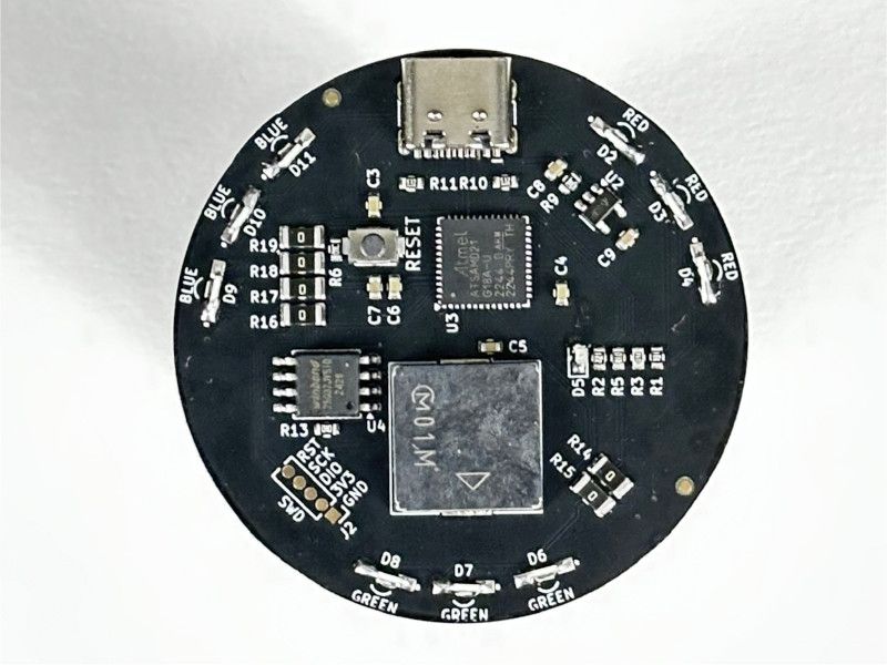
The “Coin M0” is a little round CircuitPython board with just enough features for a mini macropad.There’s an ATSAMD21 microcontroller on board with 4MB of flash, Neopixels, touch pads, and a little speaker.The Coin M0 can run CircuitPython or Arduino very nicely and the flash storage is plenty fo...
frosty dirge
It's my favorite little MCU for onboard stuff. So dead simple.
This is running ZMK though.
clever stone
I am looking forward to developing for the AVR64DU (8 bit MCU with USB). It is very budget friendly
frosty dirge
I'm seeing lots of folks go ch552 and that family for cheap 8-bit USB stuff.
clever stone
I need all of the 64KB of flash plus a little EEPROM.
scarlet pelican
My son breadboarded this circuit so we could talk to the MOS KIM-1 with my laptop: https://youtu.be/f36RJ-k_s0E

Some of the lab techs at Georgia Tech found this while sort through piles of long forgotten boxes. Luckily, they thought "let's run this by Lanterman first" before tossing it out.
Support this channel via a special purpose donation to the Georgia Tech Foundation (GTF210000920), earmarked for my work: https://youtu.be/2BnAYPB5xag
0:00 -- Intro...
clever stone
scarlet pelican
My son breadboarded this circuit so we could talk to the MOS KIM-1 with my lapto...
Impressive spelunking and a talented next generation hardware hacker 👍🏻💪👏🏼
sand grotto
TinFX-W and Micropython powered Lego NeoPixel Christmas tree 🎄
Code: https://github.com/tyeth/christmas-tree-neopixels-pimoroni-tinyfx-w/
Gallery: https://photos.google.com/share/AF1QipNleDYwzHlcNteEjaLrvq75awYH58Z31Qw7cj1WPOI7epapDlhymlNzVpuJOSPEdg/photo/AF1QipNq2aFrhsYKPCbpBf4XvHDOz3JNl2vqmOrXok6O?key=R2JweEJkY01zSklsNlcyWVFmc1RIV1YyXy1DaUhB

 languid nebula
A side question... where do you get that squirrel? It is part of the kit?
sand grotto
languid nebula
A side question... where do you get that squirrel? It is part of the kit?
Yeah, part of the small kit, couple of hazelnuts, ladybirds, and shrubs as well as the gardener (and mostly what's seen).
The axe is an old knights set
 languid nebula
Awwwwwww thanks☺️☺️
 sacred timber
sonic fractal
he just needs some bateries and hes done
sacred timber
sonic fractal
he just needs some bateries and hes done
So this is your PC board design? Looks great. Also the name of my cat... 😄
sonic fractal
sacred timber
So this is your PC board design? Looks great. Also the name of my cat... 😄
Hes a little robot i made
ill make the design files public once i confirm hes working
sacred timber
sonic fractal
Hes a little robot i made
ill make the design files public once i confirm hes wo...
Is there a ball caster under the middle-front then?
sonic fractal
sacred timber
Is there a ball caster under the middle-front then?
Yes, a very small one
 sacred timber
sonic fractal
Yes, a very small one
sacred timber
sonic fractal
Yes, a very small one
Cool. I've been thinking I might try designing my own PCB at some point, as I've got some spare N20 motors with encoders from my current project (I replaced the ones I had with more powerful ones to handle a larger robot with Mecanum wheels, so I've got 4 spares).
I like your graphics, they look good.
sonic fractal
sacred timber
I like your graphics, they look good.
Thanks
The moai isnt mine btw, i was given permission to use it by the creator
His name is RetroAdvance64
I like adding icons and such to my boards
Adds character to it
sacred timber
Yeah, sure, I have a graphic arts background (including cartooning) so I'd like to do something arty-farty with the design. A little personality...
I'd like to do a circular board so I'd have a balanced differential robot, two casters. But keep it small.
sonic fractal
sacred timber
I'd like to do a circular board so I'd have a balanced differential robot, two c...
That sounds quite challenging to do, i wish you luck on your project.
If you ever end up making it, feel free to share it with me
sacred timber
sonic fractal
That sounds quite challenging to do, i wish you luck on your project.
If you eve...
It'd be sometime later next year, as right now my main project is a small 4 wheel Mecanum, putting my Mars rover on hold since I'm out-of-country for awhile. So there's already a queue of projects, but I've wanted to try a really small 1 or 2 PCB design for awhile, avoid all the difficulties of wire harnesses by using a custom PCB. [Most of my messaging is over on Personal Robotics...]
Of course, one of the more difficult parts is choosing the batteries. I normally use 12V or 18V power tool batteries, but for a really small robot they'd probably be too big. But maybe the smallest of the Makita 12V batteries might work out, considering the alternative might be just as heavy. I'd not want to use bare LiPo batteries and I'd like a decent running time.
sonic fractal
Yeah picking the batteries was tough for me too due to the size of my robot
I ended up going for 14500 batteries since theyre small
sacred timber
So are they sandwiched between the two PCBs then?
I generally try to balance my batteries (since they're often the heaviest things on the robot) over the axles as much as possible.
sonic fractal
sacred timber
So are they sandwiched between the two PCBs then?
So i uhh
Actually domt have them yet
sacred timber
Ahh
sacred timber
No, you often can't ship batteries overseas because of the possibility of them flaming out.
Depending on the kind of battery.
sonic fractal
Yeah yeah that, the shipping company explicitly states that i cant ship lithium batteries, although im unsure if there are exceptions
sacred timber
Probably not. There's been situations where freight planes had explosions when carrying a bunch of lithium batteries so now there's a lot more restrictions. You probably need to find a local vendor like DigiKey or Mouser.
For example, if you look at the bottom of the pololu.com page they have a list of distributors by country. Some companies have distributors in most larger countries.
So even if you live in a smaller country, if it's near one on a distributor list and can be shipped by truck, you'd be fine.
sonic fractal
sacred timber
So even if you live in a smaller country, if it's near one on a distributor list...
Found one, its in another city but they do ship to where i live, thanks for the suggestion!
 topaz cipher
I recently completed a project writeup for a Personalized Digital Tree Ornament: https://www.hackster.io/rhammell/personalized-digital-tree-ornament-with-animated-icons-17742a
This ornament includes a small display, that shows animated face icons bouncing around on screen- making a nice little personalized gift for the holidays.
It uses an Feather RP2040 along with an Adafruit 1.8" TFT display.
The writeup may be helpful for anyone dabbling in displaying images using CircuitPythong and the displayio library. It gives a detailed explanation on how to make transparent bitmap image using GIMP, and how to read in and animate that image ont the display

Hackster.io
Build your own digital ornament that lights up your Christmas tree with animated face icons of your loved ones By Bob Hammell.
 ivory briar
A school project I did. I’m using an ESP32-s3 and some sensors to gather data and send to my AIO account.
Pic of the hardware
 eager flume
I got gnuboy running on my tiny console! It's running on the Arduino framework so it's really easy to tinker with. I'm now working on getting a selection menu to launch either this or my previous NES emulator. I plan on getting SMS emulation working after.
(There is one downside to this which is that GBC roms can be up to 8MB large, but I only have 2MB on this QT Py... I could replace it with a more powerful chip but then I couldn't make it this small without a PCB)
 broken rain
ivory briar
A school project I did. I’m using an ESP32-s3 and some sensors to gather data an...
broken rain
ivory briar
A school project I did. I’m using an ESP32-s3 and some sensors to gather data an...
That's really cool. Do you have a github to share the code and printables to share the case?
sand grotto
ivory briar
A school project I did. I’m using an ESP32-s3 and some sensors to gather data an...
Very interesting, and a nice project! Did you find the INA219 was reading too infrequently to be useful, or the current was too little etc, just curious as I do see a couple of peaks in the current graph (and I forget which of the current sensors does charge/coulomb counting)
sand grotto
eager flume
I got `gnuboy` running on my tiny console! It's running on the Arduino framework...
Nice work!
There's the Adafruit ESP32 qtpy pico, which has 8mb flash and 2mb psram, or you could grab something like a 32mb flash 8mb psram esp32s3 in small form factor (maybe include the display) from another vendor. This is my goto for larger flash+ram plus display (but only 16mb flash with 8mb psram and you probably find the usb+button positions less ideal) https://lilygo.cc/products/t-display-s3?variant=42351558590645
ivory briar
sand grotto
Very interesting, and a nice project! Did you find the INA219 was reading too in...
Well, those spikes in my graph are just the few times I decided to test the charge. It's supposed to be charged by a solar cell, but as there aren't many places for me to place the cell at home, it's been kinda difficult to test it long term. Also, you're right that the INA219 reads the current infrequently, but that's fixed by using a for-loop to collect multiple samples (600 worked best for me) and then calculating the average value I get. In short, the INA works, I just haven't used it to charge a lot and that is the reason for the irregular spikes in the graph.
ivory briar
broken rain
That's really cool. Do you have a github to share the code and printables to sha...
I do have a repository, but only a private one between me and my teacher, as this was a school project. Could maybe make a new public repository with the code, but must first see with my teacher then. Also, it's really messy as I'm still quite new to coding and especially to github and how that works. Also, the printable case wasn't done by me so I don't have any files for that.
sand grotto
ivory briar
Well, those spikes in my graph are just the few times I decided to test the char...
Thanks, really appreciate the detailed answer!
weary night
I have created a cellular LTE-M connected Christmas tree with the Walter module: https://youtu.be/3ue0cUZLDmw

Check out Walter: https://www.quickspot.io
It's the festive season, and Walter is spreading some colorful cheer! We’ve built a Christmas tree using a WS2812B LED string and programmed it with sparkling effects. Thanks to its LTE connection, you can change the tree's colors from anywhere in the world!
eager flume
sand grotto
Nice work!
There's the Adafruit ESP32 qtpy pico, which has 8mb flash and 2mb psr...
Yeah I was looking at the Pico, but for now I'm limited on PSRAM. Also that display looks interesting but I'm going to switch to a 240x240 screen soon as I'm currently drawing at half resolution (for the NES emulator)
Although the Pico also has a DAC so it would work with audio
 light summit
My latest lander sculpture using a Particle Photon 2 along with Adafruit’s 170x320 TFT display and PDM microphone. The display has an SD card so I can store a ton of images and graphics. Hoping to use the microphone for simple voice commands.
The lander is showing a demo screen, but the data will eventually be fetched over the internet using webhooks.
 sand grotto
eager flume
Although the Pico also has a DAC so it would work with audio
sand grotto
eager flume
Although the Pico also has a DAC so it would work with audio
Maybe an i2s amp (they're small and supported by esp and most platforms)?
untold sable
ivory briar
A school project I did. I’m using an ESP32-s3 and some sensors to gather data an...
Great job on the various display setups. Lots of info on a screen without being cramped/cluttered so still easy to read. Good siplay layout is an underrated skill.
 half marten
Tiny little thing I made, looking for some feedback around the switching regulator layout and tracing
 pearl kayak
low pulsar
half marten
Tiny little thing I made, looking for some feedback around the switching regulat...
pearl kayak
low pulsar
half marten
Tiny little thing I made, looking for some feedback around the switching regulat...
(not feedback, but learning from your design) was part of the thinking to be breadboard friendly? - if yes, are the header pins positioned to plug into a breadboard in that orientation to power up the rails?
half marten
low pulsar
(not feedback, but learning from your design) was part of the thinking to be bre...
Yes the idea is it make it as plug and play as possible, it powers the breadboard rails to either 5.0 or 3.3V
clever stone
half marten
Tiny little thing I made, looking for some feedback around the switching regulat...
I may not be reading your PCB layout correctly but it appears you have your 5V and 3V pins in a row that is covered by the PCB.
Are the soldered headers for your PCB point up and thus not touching the headboard?
If not, then the pins of a row are connected, your U+ and U- are shorted together. They are also covered up by the PCB.

This image is just a reference to show you how the pins of a breadboard are connected.
A popular layout is to have VCC and GND pins align with the left and right edge rails with pins down so the power PCB plugs directly into the breadboard.
Here is a 3D party example:

 potent aurora

It power the power rails only
the headers along the PCB are upwards to be accessed with wires or for testing points
also the selection happens through the upwards pins aswell
its manual, to prevent unconscious decision to shift voltages from 3.3 to 5.0 and vice versa
This one an older version however
still waiting on JLCPCB for v2
low pulsar
potent aurora
thanks for the visual 👍🏿 (I didn't recognize the smd 2x3 pads on the back side, nice.)
sonic fractal
light summit
My latest lander sculpture using a Particle Photon 2 along with Adafruit’s 170x3...
Omg dude im a big fan of your work
I used to follow you when i had IG
half marten
Redesigned Arduino R4 Minima
https://www.youtube.com/watch?v=MV3ItGxBP1M

 daring timber
I've made a tool that can be described as a CI/CD system for the RP2350/RP2040. I hope this could make your development workflow more convenient.
Please take a look, feedback appreciated: https://flashmypico.com/
 bright sky
Wrote the drivers for this lcd panel for Kaluma.js that runs on a RP2040. Wrote some other tools to convert pngs to embedded json bitmaps too. Got some rudimentary orientation code going.
half marten
Cute!
eager flume
eager flume
I got `gnuboy` running on my tiny console! It's running on the Arduino framework...
https://github.com/simplyrohan/esp32-gameboy-color
repo if you want, still a WIP but its not too bad to port to your own setup if you modify hardware.h and hardware.cpp
GitHub
An Arduino powered Gameboy Color emulator! Contribute to simplyrohan/esp32-gameboy-color development by creating an account on GitHub.
untold sable
bright sky
Wrote the drivers for this lcd panel for Kaluma.js that runs on a RP2040. Wrote ...
Which display is that? Nice job btw.
bright sky
@untold sable gc9a01
 solar yew
I hope you all are well! I am the creator of the Raspberry Pi Recovery Kit and I am in the process of bringing everything over from my doscher.com site to my Github account here: https://github.com/jdoscher. If you see something missing, @ me and I will add it :). Cheers!
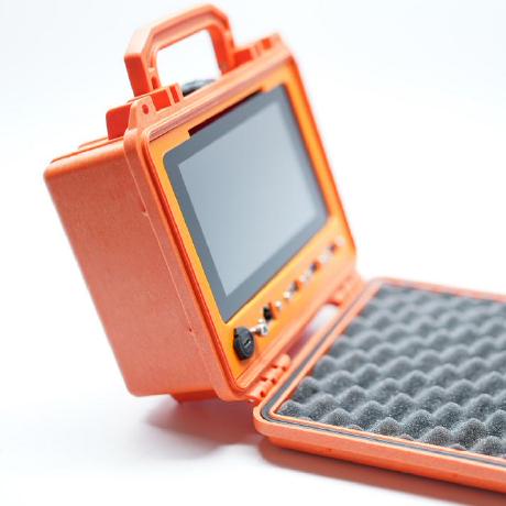
GitHub
Maker, Designer, and Sometimes Coder. jdoscher has 31 repositories available. Follow their code on GitHub.
 swift nexus
I picked up some NOODS during the holiday sale and wanted to make something that made use of the flexibility, so I made a tensegrity table desk toy: https://hachyderm.io/@thzinc/113763212970483778
Attached: 2 images
Aww yeah! I printed and built my tensegrity table with NOODS from @adafruit@mastodon.cloud. I’m very pleased with the outcome.
Looking forward to writing up the build process on this one.

 bright sky
Using shift registers for the first time right now. Fried a microcontroller tonight but finally got it working. I’m emulating a NES controller on a bread board and using switches so I can “slow it down” as I work on another shift register to decode the serial out to do parellel out for a gameboys inputs.
 wind nest
I am currently building a pick and place machine to assemble PCBs dose anyone want some pictures.
low pulsar
Nice 🙂 (I've never even held a Gameboy, a naive question.) how does one interface with a Gameboys input? Briefly looked at some diagrams, and saw a diode matrix for the buttons.
clever stone
wind nest
I am currently building a pick and place machine to assemble PCBs dose anyone wa...
Wow! Are you using a kit or building from plans? I have been curious about the kits as well as the few available desktop machines.
bright sky
low pulsar
Nice 🙂 (I've never even held a Gameboy, a naive question.) how does one interfa...
So there’s 4 wires that the game boy reads d pad and buttons from. There’s two control pins/wires that flip high and low for switching the diodes between d pad and buttons. So the game boy uses 6 pins instead of a full 8 to read the controller inputs.
bright sky
low pulsar
Nice 🙂 (I've never even held a Gameboy, a naive question.) how does one interfa...
I created an interactive web (react) app (not deployed yet) that illustrates the button states in slowmo to illustrate it more.
stiff coral
A sneak peek at the near finished Fartsichord. A farting circus organ. I built the wood cabinet myself and it runs off 16 neokeys (8 for the gold buttons on the front, 8 for the farting piano keys) the gold buttons on the front play cartoon sfx and there will be 8 piano keys that play fart noises. The last thing I need help with is getting the fart keys to light up a separate led for each key when pressed. This also has a raspberry pi music player coded by my friend Alex. The player has an external usb mount so I can add more music to it. The text was printed on parchment printer paper and glued onto the wood recessed window. A WIP but it’s almost done

 daring timber
Hi! I'm back with a new RP2350/RP2040 feature that lets you pre-configure firmware constants before flashing: https://flashmypico.com/docs/howto/configurables
wind nest
clever stone
Wow! Are you using a kit or building from plans? I have been curious about the k...
The kid costs way too much. I have built him for about $400.
wind nest
*kit
and it is based around the lumenpnp but heavily modified tol cost under one thousand
lucid bloom
A heavily augmented yet completely unmodified Mac SE. My friend modified the floppy so it boots into the tts program. There is a USBWombat and PicoW which makes it say the contents of an mqtt message by typing it in then Ctrl T to make it say the message. The accelerometer is a mpu6050 and d1 mini which allows it to respond to being poked. The most recent part on top is a pi zero 2 and waveshare wm8960 with stereo mems mics which enables the conversational aspect.
 stiff coral


The Fartsichord is done! Huge thanks to @glad roost for helping me along! I’ll post a video at some point
Made the cabinet and all the bells and whistles myself
Still have to attach the back hatch
stiff coral
Now it’s finally finished!!!


 smoky heath
Makes me think of when he was a guest at Late Night and brought his fart machine 😉
 craggy yew
I true marvel indeed!
clever stone
stiff coral
What a gas!
untold sable
clever stone
What a gas!
Jumpin' Jack Flash!
clever stone
untold sable
Jumpin' Jack Flash!
♭- flat
sharp comet
swift nexus
I picked up some NOODS during the holiday sale and wanted to make something that...
that looks really cool, great job!
It's not hooked up to RTC or other real time source yet, but I'm pretty happy with how this displayio analog clock face is turning out.
swift nexus
sharp comet
that looks really cool, great job!
Thanks! I wrote up the build at https://thzinc.com/2025/01/03/illuminated-neon-tensegrity-table-desk-toy.html
Last month, I added some of the 300mm NOODS LED strands to my Adafruit order because they were on sale...
sharp comet
Awesome! thanks for writing that up and sharing it here. I love the wobble that it does.
woeful depot
Hi all!
My current project is called SPOKE, it is a 27-pin capacitive touch controller based on the RP2040 chip from raspberry pi. It has 27 neopixel LEDs that work as indicator lights and also has connectors for i2c devices for additional inputs/outputs or daisychaining boards together!
It runs on Circuitpython so can easily be coded to do lots of different things. So far I've experimented loads with USB-MIDI, Keyboard and Mouse emulation for game/software controllers and also using serial-in for controlling other things.
I'm starting a kickstarter for it soon, as it has the potential to be a really useful tool for makers/educators, currently just building an audience who might be interested in supporting it!
https://www.kickstarter.com/projects/tomfox/spoke-touch-sensing-made-simple

Kickstarter
SPOKE is a simplified capacitive touch sensor board for interactive computer interfacing.
swift nexus
sharp comet
It's not hooked up to RTC or other real time source yet, but I'm pretty happy wi...
Round displays are so cool
sharp comet
Agree'd!


 wind nest
I have created my owbn microcontroller moard around the pic16f1455


GitHub
Contribute to AdamKirby07/Biscuit-MCU development by creating an account on GitHub.
it is cammed the Biscuit microcontroller or biscuit mcu
It has usb to program, a battery connector for non litihum batteries and 8 io pins
i have created my own drag and drop ide, mplab can be used (microchips oem ide) and i am working on an arduino core.
*called
if anyone wants to join the waitlist go onto the discord linked at the bottom of the github and send a message in waitlist