#help-with-3dprinting
1 messages · Page 13 of 1
 faint sky
brads are for very lightweight things. for a book shelf you'll want something much thicker and something that can be used with much larger drywall screws.
brads are like .5mm or 1mm they're tiny like staples.
 iron remnant
Oh, neat. I printed a whole bunch of LED mounts that clips to the shelves in my geekroom, except I was going for plain COB strips so there's a bit of material there to act to diffuse the light.
 misty gyro
faint sky
brads are for very lightweight things. for a book shelf you'll want something m...
misty gyro
faint sky
brads are for very lightweight things. for a book shelf you'll want something m...
Chiming in here (again), you need to be careful when mounting things to a wall. In particular sheetrock isn't all that strong. If you're mounting anything heavy you really want to use a stud-finder and put a decent sized nail or screw into a stud.
iron remnant
The dad joke of pointing the stud-finder at yourself is, of course, entirely optional.
 coarse coral
Yeh I was thinking on the lines of angle brackets as a triangle to reach out to the distance but I doubt it would support. I'll maybe use the 3d printer as a solution for this but likely it may end up within a cabinet since a cabinet will act as an enclosure at the same time
coarse coral
faint sky
brads are for very lightweight things. for a book shelf you'll want something m...
Yeh it needs a good amount of attention to think it over
coarse coral
misty gyro
Chiming in here (again), you need to be careful when mounting things to a wall. ...
I'm just going to go with @iron remnant s advice
iron remnant
So, here's what I ended up doing

It's all 2020 extrusion that I got pre-cut from Misumi USA. So the goal was to hold a printer (I sized it so it'll fit my current printer or the larger printer I'm probably going to upgrade it to) and all of the accessory bits like filament, plus my networking gear and linux box, plus whatever else happens to fit.
For me, at least, it's a lot easier to switch to a fully enclosed printer instead of making the printer space enclosed. The doors would smack into the adjacent shelving (it fits in a corner) and also part of the advantage of an enclosure is that the print is stronger and warps less because the enclosure holds in the heat.
And then the nice thing about 2020 extrusions is that they are open to a lot of modifications. So I've got a Honeycomb Storage Wall 2020 mount that I need to post at some point, plus a lot of cable management and DIN rail mounting stuff.
 acoustic quiver
Hi there, I have an Elegoo Neptune 4 Pro, and am currently trying to do PID tuning on the heat bed and at the end of the process it comes up with an error saying !! pid_calibrate interrupted and Can not update MCU 'mcu' config as it is shutdown
Has anyone else experienced this issue? or have any pointers on how to resolve it?
I am running Firmware Version V1.1.2.03 and UI Version 1.2.4
coarse coral
iron remnant
For me, at least, it's a lot easier to switch to a fully enclosed printer instea...
This is a well thought out stand for a single printer I like it a lot, and also could be good because u changed my thinking that the printer would be on display in my lounge since it's pretty quiet but having this type of solution means there's space for filament it can be enclosed and further to that I have a wall cupboard that it would sit really well within which is external vented. This mean I can line up my print and forget about it with all those benefits plus the benefit of not looking at the print after first layer until it's finished (developed this habit with printers I had trouble with).
Neat! Ideas!
coarse coral
acoustic quiver
Hi there, I have an Elegoo Neptune 4 Pro, and am currently trying to do PID tuni...
Sorry I have a Neptune 3 plus but haven't did pid tuning yet
faint sky
Just happened to me. Over time the nozzle worked its way loose and I found it inside the spaghetti mess. Both the nozzle and sock came off. I know for a fact I tightened the heck out of the nozzle when I installed it, and it was on a brand new extruder that never had filament through it before. This will likely be a recurring issue as it's happened to both my sprite extruders now.

This is likely another culprint for when people get giant molten blobs around their hotends. It requires manual labor to clean up (while the hotend is hot).
I think it's due to the way filament is twisted or when the nozzle moves over a part and meets rotational friction, it slowly loosens over time.
I had my printer dialed in extremely well so when I had to raise the z-offset by .5mm and noticed molten filament coming out the side of the silicon sock, should have been my first clue. 5 minutes later the nozzle and sock and were on the bed surface along with some spaghetti when I came to check on it.
Now I'm thinking that nozzles need some way of keeping them in place like a cotter pin or locking mechanism because this is the 2nd brand new extruder this has happened with.
Yes I have 2 sprite extruders. 1 is for .4 nozzle and the other for .8. It's much easier to swap out the entire extruder assembly than just the nozzle.
 misty oasis
Ok hello again,
I had a friend come over who’s experienced and he couldn’t figure it out either. Something’s wrong with the balancing of the heat bed he said. Unsure what that means, and now unsure what to do next.
faint sky
Tighent the vrollers on the y-axis (front to back) bottom? With too much free play on the vrollers it might make the carriage tilt side to side.
 vocal flax
I'm having problem with bed leveling left of the bed always low compared to right side. Its i3 style bed slinger. I've tried leveling gantry (both manually with a caliper and g29 (individually driven z). Trammed bed both manually with a paper on 4 corners and with tramming assistant in marlin. Tried glass bed and pp bed, (glass unfortunately shattered can't show it right now). I am out of ideas.


Any ideas on what might be causing this
faint sky
What printer specifically? Left side definitely a hair lower than right. Does it have automatic leveling and/or adjusting screws?
It's not off by much but noticeable enough to cause quality issues later in a print. Off by about .15mm
Does it have a pinda style probe for autoleveling and bed mesh?
vocal flax
I have automatic leveling and adjusting screws
Ive already said it's i3 clone. Prusa style bedslinger
It has a touch probe with opto interrupter
faint sky
Do manual probing with a sheet of paper starting in the middle first. Then do the outside corners, repeat that a couple times until you've got everything trammed like you want. Then do an auto bed probe. The more level you can make the entire bed prior to bed probing the better.
vocal flax
M48 gives good enough results
As I said, tried both manual tramming and assisted tramming
faint sky
You mentioned gantry though, are you concerned it's not square somehow?
ok then AFTER the bed mesh is created then you can still tweak it with the adjusting screws. bring that left side up a little?
vocal flax
I've tried to level gantry to bed to y rods and to motors as reference points all same result
vocal flax
faint sky
ok then AFTER the bed mesh is created then you can still tweak it with the adjus...
Then next print the left side is low again.
Using auto bed level every print
vocal flax
It probes 4x4 matrix every print
faint sky
in which case yes i'd be concerned with the gantry being a hair higher on the left.
vocal flax
faint sky
in which case yes i'd be concerned with the gantry being a hair higher on the le...
I've tried 3 different method of doing that no luck
faint sky
fixing a .15 or so deviation with the gantry isn't trivial... but the bed probe should accomodate for that, so your bed probing isn't working as it should either.
faint sky
i would do a bed probe, make a mesh, then disable it from doing it every print. that way you can make the screw adjustment once and then never touch it again.
i have no experience with i3 only enders, unsure how that will translate.
vocal flax
That's a workaround and probably a good workaround but it doesn't solve the problem
faint sky
it does if you never touch it again and only use bed probing when something changes. that's how i use my S1 pro and works quite well.
vocal flax
I3 is the same thing but it has real linear rods than v grove sigma
faint sky
my bed probe only comes down in the center once per print just to verify bed height, and uses the same existing mesh every time.
there are others here with rod experience that hopefully with jump in. i've never owned one with rods, well except the Anet A8 but that was a decade ago.
vocal flax
It's not a solution, it's a workaround and credits to you it's a good one. Unfortunately, I have 2 different bed surfaces, glass and pp sheet. And I sometimes use heated sometimes not heated. I have 3 combinations of bed.
faint sky
yeah sorry that's all i have for you 😦
vocal flax
It doesn't work for me. Also, this printer is a hobby itself, so would like to solve it
vocal flax
faint sky
yeah sorry that's all i have for you 😦
No worries thanks
faint sky
maybe try Prusa support discord? there's gotta be some specialists out there.
vocal flax
faint sky
there are others here with rod experience that hopefully with jump in. i've nev...
My thing is very close to anet A8 tbh
vocal flax
faint sky
maybe try Prusa support discord? there's gotta be some specialists out there.
I tried 608 wasteland, I guess I can try my luck there
faint sky
problem i had with the A8 was the rods warped and rusted over time. rods only work when they're perfectly straight and cheap rods just destroyed the entire thing.
not to mention the entire thing was a complete fire hazard waiting to happen
vocal flax
Oh I don't have that problem, mine are alloy and has thick plating or something. Could be outside induction hardened I don't remember.
Haven't seen any wear or rust on rods for 10+ years
faint sky
well i used it in a garage, in florida, high temperature, high humidity, turned everything into rust within a year. it was cheap cheap horrible quality A8.
vocal flax
The marlin config is my own no fire hazards here 👌
faint sky
the fire hazard was the A8 PSU and wiring
vocal flax
Custom built, bought piece by piece
faint sky
very nice! hope you figure it out. if you do please come back and let me know what fixed it. all i can think of is tricking the bed probe.
vocal flax
My prime suspect is rigid couplers, which has no basis, I just am out of options and change everything I can
If that doesn't solve Ill turn table 180 degrees to put double bearing side on the right
Again has no evidence these could be it
Actually I might do 2nd first because it makes sense to have something wrong down than up
 misty ibex
@faint sky did you finish your new infinity mirror?
coarse coral
vocal flax
I'm having problem with bed leveling left of the bed always low compared to righ...
Left just looks off. I don't know if you have build plate tighteners but why don't you just lower right a touch and bring up left?
Seems quite straight forward I know.
faint sky
misty ibex
<@126221640559362048> did you finish your new infinity mirror?
No it's in the pile of unfinished projects. Had to take a vacation, then work on halloween stuff, then get back to it. Month went by and forgot to get back to it.
misty ibex
I hate it when that happens...
 torpid jasper
“Pile of unfinished projects” implies a “pile of finished projects” and frankly I’m not sure such a thing exists
 balmy pulsar
no such thing as a finished project
vocal flax
coarse coral
Left just looks off. I don't know if you have build plate tighteners but why don...
As I explained again and again the error is repeatable, if I adjust left gets low again
coarse coral
Maybe your springs are weakened
vocal flax
Springs are tight. I've tried very compressed less compressed different ways of tramming
Result is same always
 shy kelp
Something like tpu or silicone, but cheaper?
Latex is cheaper, but it's a pain to work with, if you need some thickness
 tardy juniper
Hey, so I have a CR10 Smart but for some reason, it is autoleveling but then ignoring the auto level data when it goes to print
I cant figure out whats causing this
Also when it prints I have to set my z offset rediculously high which I think is also due to the same issue
faint sky
You must add gcode to your slicer machine start gcode settings (in Cura) to use the bed mesh otherwise it will ignore it.
Each sliced model gcode file is embedded with the code to use the bed mesh or not.
For my S1 Pro it never used the bed mesh until I added M420 S1 Z10

You have to look up your slicer software settings for your printer and figure out how to add the gcode to use bed mesh. M420 S1 Z10 only applies to Marlin. If you're using a Bambu or Klipper you have to figure out how to do that on a software basis.
tardy juniper
Thanks thats perfect
I think thats exactly what I was missing. No idea why I couldn't find it anywhere online
faint sky
Use G28 prior to that to home all axes first too
faint sky
Remove G29 in favor of G28 and M420 S1 Z10 both.
tardy juniper
Oh so no g29?
M420 S1 Z10 will auto level?
I thought that only told it to use the saved auto level mesh
faint sky
G29 does a bed probe prior to each print which is unnecessary if you do M420 instead
tardy juniper
Will M420 auto level?
faint sky
So do an autoleveling with your control pad. Add G28 and M420 lines and it will use your last autoleveling bed mesh.
tardy juniper
Ok
faint sky
G28 will home all axes and do 1 single probe in the center to confirm bed height. Then it will go to the closest left corner, use the M420 bed mesh, and start on purge lines when nozzle temp and bed temp are reached.
This makes it so you only ever have to use autoleveling when something changes. It will never do a full 16 point (or how ever many probe points you have) again until you manually do it again. It saves so much time prior to each print.
When you do it for the first time have your hand on that z-offset compensation to move it up/down on your first print. As it's printing the purge lines that's when you do your final z-offset compensation.
It's mostly to help avoid bed scraping but also will ensure your first layer goes down at just the right z-offset you want.
From then on both your bed mesh and z-offset will remain the same every print... and you can print forever like that.
M420 itself does not do autoleveling no, it only uses the mesh from your last autolevel probing.
As long as you have that line in your printer settings it's exported with every gcode file you create.
Therefore your printer interprets that as always use last saved bed mesh.
You can redo autoleveling at any time and your gcode file will use that new bed mesh instead. Autoleveling creates the bed mesh.
The first thing I do is a manual bed level, get everything as perfect as you can, then do autoleveling for the bed mesh.
Your manual leveling cannot be more than 1mm off on any corner. Autoleveling cannot compensate more than 1mm deviation.
tardy juniper
Ok so I left in the g29 just to get it to level before printing (using m420), but it seems to not compensate still
Like the z axis screw is just stationary until it goes to the next layer
faint sky
 tardy juniper
Thats how my prints used to look 😭
Is it possible that since it g29'd in the same print as when it tried to load the mesh from eeprom that there wasn't a mesh?
Also is there a separate command for saving the mesh to eeprom or does g29 do that by default
faint sky
unlikely but with this method you can redo autoleveling as many times as you want to create new bed meshes and the cgode will use the new one.
faint sky
tardy juniper
Also not sure if this helps, but my z offset is currently at the max value
And if I decrease it at all the nozzle is too close
faint sky
do you have increment set to 10mm?
faint sky
use .1 or .5 increments
faint sky

Accessories purchase, Please contact our official email or website, remember to attach your machine type and accessories pictures
Official email:info@creality.com
Official website: https://www.creality.com
Any technical support in need, Please contact our official service email,remember to attach your printer model、complete orderscreenshot、purch...
Do not use this video for guidance, it's complete garbage and extremely deceptive.
tardy juniper
🤣
I haven't seen that one honestly
But I'm not suprised, crealitys products are kinda trash lol
faint sky
Your touchpad is setup a lot like my S1 Pro.
faint sky
Not sure what you mean by max value... I've never maxed out z-offset compensation.
faint sky
🤦♂️
 faint sky
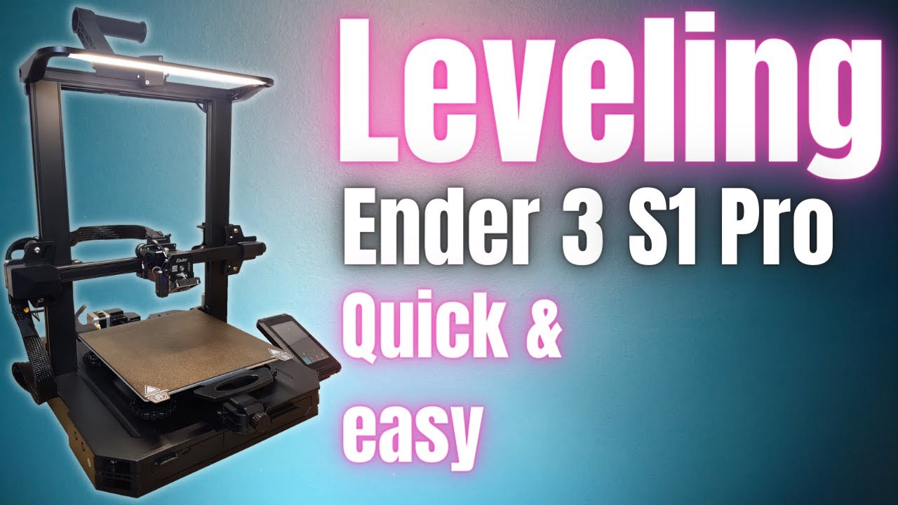
Leveling or Tramming the bed on your Ender 3 S1 Pro 3d printer is quite a quick easy process, but it's one that can cause some issues if not done right.
In this video i'll show you how to set your spring pre-load, manually tram your bed and then use the automatic leveling feature to create a bed mesh.
Bed level test stl file: https://www.thing...
 faint sky
That video by Ricky Impey is really good and should be close enough to adapt for your uses since your touch pad is very similar.
faint sky
and for people who have odd leveling issues due to gantry alignment issues there's this one to pay attention to.

One of 3d printing's biggest problems, especially when you are new, is levelling your bed.
In this video I'm going to give you 3 simple things you can do to put your levelling issues to bed once and for all.
.............................................................................................................................................
It's easier for me to link videos than to write paragraphs on this stuff over and over. If you have a printer issue the first thing you should be doing is scouring youtube for videos on the subject. Most everything I've learned about 3D printing has been from Youtube.
tardy juniper
Oh yeah for sure
My issue was just finding anyone who was experiencing the same issue 💀
But I do think the links you sent will give me the right direction, so thx
faint sky
I hope so, good luck. If you can't figure it out I'm always here.
tardy juniper
For sure, thanks!
faint sky
Finished installing the printed u-channels for the side-lit strips. Took about 10 hours of printing. Has a PIR sensor for motion activation.
 vocal flax
@tardy juniper if you go devons' route make sure you use store settings option. Default marlin option is to scrap any bed leveling data prior to homing and m420 brings values from eeprom (or equivalent) which is normally zeroed out during flashing
faint sky
G28 doesn't delete a bed mesh it only disables it. If the very next command is either G29 or M420 it is reenabled. So the combination of G28 and M420 is homing, disable bed mesh, enable bed mesh. If you use G29 it will take a new bed mesh prior to each print. If you use M420 as long as you don't physically change anything the same bed mesh will always be valid. This is why I do not touch the bed surface AT ALL, EVER, and I certainly don't remove and flex the bed surface to pop off prints. If it ain't broke don't touch it. M420 will work forever.
However as I've recently discovered you do have to account for possible nozzle unscrewing itself. I didn't believe that was a real thing until it happened to me. When it started unscrewing it lowered the z-offset the more it came unscrewed and yeah it gouged my bed a tiny bit in one spot. So even if you do everything perfectly correct, things can still go wrong.
coarse coral
I opted to disassemble my printer and rebox for moving and I only had one job but managed to break one of the small wires in the process
vocal flax
faint sky
G28 doesn't delete a bed mesh it only disables it. If the very next command is ...
If you haven't store it on non volatile memory, m420 brings values from non volatile memory (which is erased when freshly flashed) then you lost the bed leveling information. I didn't said g29 erases it.
faint sky
How often do you flash your firmware?
vocal flax
If he never leveled the bed and stored the settings (write to non volatile memory) it's safe to assume no data (all 0es) pulled from memory
faint sky
Some of the newer enders don't require manually storing to eeprom. It's done automatically during autoleveling.
Which is why you want to manually level as perfectly as you can before running autoleveling. After that is the final adjustment of z-offset while the purge lines are going down on your first print.
He said he did level the bed manually and with autolevel but his prints weren't using the bed mesh because he was missing M420.
The reason I'm against using G29 every time is the probe will rarely measure the same data every single probe, there's variability. You remove the variability with M420 and can adjust to that manually if needed. I know it sounds weird but it works. G29 can have you chasing your own tail sometimes when the prints come out slightly different every time and that's because it's taking a new bed mesh every time prior to printing.
In an ideal world G29 results will be identical every time. In reality, in my experience, far from it.
coarse coral
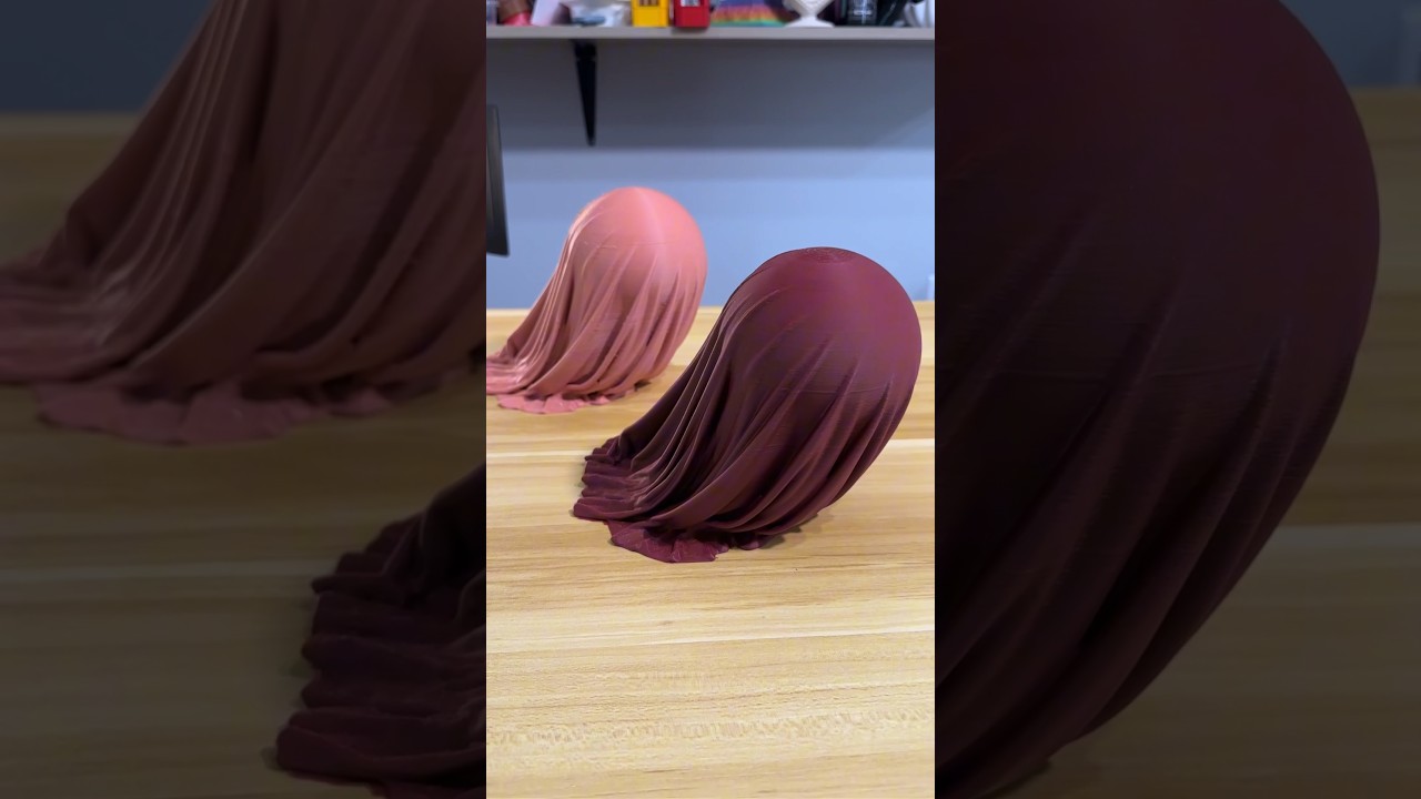
An amazing sculpture you wanna see? Here it is! An invisible ball under a cloth by @extreme3dprint 🤩 Our fifth candidate for the Top 10 video 😬 its gonna be cooool
I just loved this. An amazing halloween decor for sure. Also I did some asmr content for my ears. 👂 I love the crunch. Available on @cults3d
What do you think 🤔
#asmr #halloween ...
His first print is so clean
vocal flax
faint sky
In an ideal world G29 results will be identical every time. In reality, in my e...
G29 is not supposed to be identical every time because thermal expansion (of bed and many other things on printer) is random (enough).
Not leveling every time will be good enough for 3d printing
Also you can test your probe to be good enough for the application with m48
faint sky
That's true if you're experimenting with different filaments. Good point. I've been using the same stuff for so long I don't have to touch anything.
If I were to go back to printing with PETG yup I'd have to recalibrate again.
Different nozzle temp with different filaments = different viscosity which would require z-offset changes at the very least.
 oak cairn
gex
faint sky
Modified a Pi 5 model to include their active cooler.


Not perfect but should be close enough for an enclosure design.
balmy pulsar
radus on the fan hub too big. also doesnt have the ejector pin mark. fail
😛
looks nice
faint sky
 balmy pulsar
haha
faint sky
Yes I completely guessed on everything, didn't measure a thing with calipers. 😛
balmy pulsar
hehe
yeah. im used to being given a couple bad photos of a car and expected to make something that seamlessly transitions from live action...
these days we have scanners, so much nicer
faint sky
I'm too lazy for that. Only needed a rough estimation. The enclosure is going to be about 3x the size of the pi because of an external SSD.
I have a stupid idea of making a kind of windmill from the exhaust fan.
balmy pulsar
yeah. its nice having models for making stuff. so glad so may suppliers give them out
windmill haha
faint sky
 faint sky
kind of something like that where the air gets directed into a cone that blows a rotating thingy.
balmy pulsar
why a cone? to accelerate the air?
faint sky
a whimsical enclosure
yes because the fan isn't that powerful so the heat will help act like a geothermal vent along with directed airflow... that's the idea anyway.
balmy pulsar
hm
faint sky
but it won't be like a real windmill because there aren't enough blades
balmy pulsar
and theres no mill
faint sky
will be more like a paddlewheel
faint sky
 balmy pulsar
the wind turns the fan blades. then mechanically spins the paddle wheel, whuck paddles waht?
a creek?
faint sky
yes it will be stupid but it will be my kind of stupid
faint sky
there will be no water involved, pi's are hard enough to get as it is.
balmy pulsar
hahahaha
faint sky
hoping the cone will increase velocity like a turbine
balmy pulsar
indoors?
im still lost. a fan (from a pc?) is gound to blow air on another fan in hopes of spinning it?
*brain broken, does not compute, NAN
i am trying to launch my keycaps later today. got a few more things to do, take a bunch of pictures etc

 elder oxide
balmy pulsar
elder oxide
balmy pulsar
The packaging is really nice
balmy pulsar
thanks
im pleased with it mostly. lots of little things to improve next go around. but for this week, im done haha
my cnc machine (one servo) died while making a vacuum fixture to cut these out. so i ran out and bought a cricut.
actually not that bad a machine haha
faint sky

General idea, it's impractical but I like the idea because it's impractical.
It's a Pi Wheel case...
faint sky
shut up no
balmy pulsar
haha
faint sky
😢
faint sky
I still don't have a way to power it on so didn't know that lol
balmy pulsar
yeah, fans blow into the heat sink then the air exhauts out the sides
faint sky
glad i didn't go any farther with the design you saved me a lot of effort. was going to make a little cottage around it and everything. 😦
balmy pulsar
eek
i bet you still can. just need to harness the air differently
that type of paddle wheel is for water as well. youd need something that will atch air better
faint sky
Can always add an external 5V blowing up but that would defeat the purpose. Maybe can do it on top of the SSD I'm sure that'll get warm.
yes was just a rough design to show the concept
balmy pulsar
ah
pic of the real pi fan?
im betting it also blows air on the heat sink beside it
faint sky
i posted one, scroll up, already installed.
balmy pulsar
cant see the side
faint sky
There is no real holes on the side which is why I thought it blew up.
it's just a square tin can all the way around
balmy pulsar
...
faint sky
 balmy pulsar
it must all come out the bottom
faint sky
eh tried powering it via usb c from the pc but didn't like that. spun the fan for a second. it spins clockwise.
balmy pulsar
no im right, its on the side with the fins.
 faint sky
aww crap
faint sky
right, I would fully expect it to blow up but they're the ones that have put a ton of R&D into it so they'd know best.
too used to PC exhaust fans i guess
there's no slots to blow it toward the heat sink either. it's just to put airflow across the entire metal plate.
🤷
balmy pulsar
no, would never blow upward. that creates negative pressure under the fan and would not cool anything.
same reason your pc case fans blow in
with the rear exhaust being the optional one
but the fins on the heat sink are sideways. obstructing the fan exhaust
just makes it look like an afterthought
faint sky
if there was enough vent space to draw heat up below the can that would work. i guess they wanted as low profile a solution as possible.
elder oxide
It’s easier to push air through than pull it through
balmy pulsar
no. fans always blow into the heat sink
elder oxide
Physics are weird lol
balmy pulsar
never the other way
faint sky
if it's in an enclosure then it's just going to recirculate the warm air inside back into the fan.... i dunno.
elder oxide
It all has to do with the pressure system created by the fan and it’s contact area with the heat sink
balmy pulsar
your enclosure needs to guide the air in and out
faint sky
knowing this will change my case design a little to ensure it can suck outside air in from above the fan.
balmy pulsar
otherwise the fan will serve no purpose.. liek on a steam deck :x
faint sky
making an enclosure for this just got a little more complicated :/
balmy pulsar
you an also make your printed case shroud the fins, guiding the are to an outlet
faint sky
i have some mesh grill for pc fans, can just make something to incorporate some mesh.
balmy pulsar
real enclosures are serious business. they may loock like a tin box, but they take into account a lot of physics
i think most pi enclosures are just boxes though, haha
faint sky
yeah most enclosures i've seen are purely aesthetic.
balmy pulsar
yup
i remember the first ibm server we got. was the first case id ever seen where the maker clearly took airflow seriously. several injection moulded ducts that channeled air
as opposed to the typical row of 40mm fans that did very little
faint sky
the problem with ducting in 3d printing is removing the support material
balmy pulsar
open side ducts. channels. not tubes
the pcb is the 4th side of the duct
in the context of a pi case, it would be like ribs
that are in highly specific locations
iron remnant
I had a bunch of aspirations of doing a more elaborate DIN mount Pi case with fans and ducting and stuff but instead I just printed a simple one and never got around to doing the fancy version.
I did do, long ago, a mockup for what a modern chassis designed to look and be shaped like the Mac IIci/cx/Quadro 700 case from the days of yore and at least one guy nagged me because he really really wanted me to make it real.
And, like, sure there's plenty of mac-esque pi cases but the scale is all wrong.
faint sky
Finding a square display that exactly matches the Mac would probably be the hardest thing. Unless you did some kind of CRT bodge but then the Pi would be inside close to the CRT and get a ton of interference.
I think it would be cool to make a modern version with a widescreen with HDMI. A modern take on a classic. Nothing wrong with that in my opinion.
Just don't post it to Mac enthusiast forums, they'd get frothy.
iron remnant
Well, I was mostly going for the afforementioned IIci/IIcx/Quadro design.
If I wanted to make the Mac enthusiasts frothy, I'd make a replica IBM PS/2 Model 25 but with Apple logo and colors.
faint sky
or just build an m-ATX mid case PC and slap an apple logo on it with a Windows 11 desktop.
I think my build volume might be enough to print an entire Mac classic. Problem is I really don't feel like squinting anymore and prefer the really big monitors of today.
iron remnant
Well, the notion I had was to get a MicroATX motherboard, a SFX power supply, and space for the usual accessories and a fully faithful implementation of the design guidelines.
Unfortunately it's still 400mm on one axis.
faint sky
print in half, solder melt it together, bondo, sand, paint?
iron remnant
Actually, no checking the file, it's 320x400mm so it's gotta be drawn and quartered still no matter what.
Assuming anything smaller than a 350mm x 350mm bed.
faint sky
Most ideas sound way better in the mind, sometimes just have to let ideas go. I have a desk full of half completed projects from always getting sidetracked with new ideas.
iron remnant
Yeah, like, I designed it as a learning project.
And I posted photos in case it eventually would cause someone else to go through the trouble of launching a kickstarter for the best retro Apple case design.
And, really, I don't have room for a random extra PC solely because I wanted something cute like a Mac IIcx.
coarse coral
Will putting my 3d printer in a closet which isnt much more in size than the width and depth of the printer have similar benefits to an enclosure?
Does vertical space play a part in this, it's basically a floor to ceiling closet usually for hanging coats.
I'm thinking of just making a shelf for the printer, nothing much really.
coarse coral
faint sky
Sorry but this design although it may be total genius still seems hilarious
iron remnant
So, check this out: https://www.youtube.com/watch?v=WrQiUL0jAzc
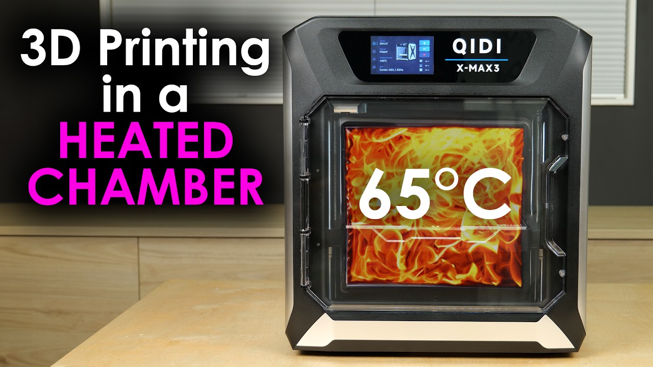
Thanks to QIDI for sponsoring this video. Check out the QIDI X-Max 3 here https://geni.us/QIDI3D and get a special discount with code CNCKITCHEN30
It is common knowledge that higher technical materials should be printed in a heated chamber. But why do they warp less when printed in a warm environment, and how much stronger do they get? I used t...
A closet is going to give you some potential benefit from microplastic and VOC pollution
It's probably not going to maintain the heat like an enclosed printer would.
But also small aerosol particles and gasses are not necessarily easy to wrap your brain around the transport of, as evidenced by COVID and some of the less effective measures of protection.
coarse coral
Thanks @iron remnant looks like anything where ambient temps are close to printer temps delamination is less and strength increases. Looks like the printer will be in the closet for 3 reasons now. It doesn't take up floor space and as above.
faint sky
I wouldn't put it in a closet that has your clothes as a fine particles will coat everything eventually. An empty unused closest would be ok.
faint sky
A Ring Doorbell Enclosure that acts more like a wireless security camera by hiding the doorbell light.
 coarse coral
faint sky
I wouldn't put it in a closet that has your clothes as a fine particles will coa...
coarse coral
faint sky
I wouldn't put it in a closet that has your clothes as a fine particles will coa...
Yep this will be a single purpose closet (it's actually a walk closet rather than IKEA) and it looks like this could be the ideal purpose.
faint sky
and I made it backwards. It's supposed to be angled in the other direction. Noticed after the 7 hour print finished. 🤦♂️
coarse coral
The plus is i can't imagine it used many grams of plastic?
 arctic dragon
It’s still 7 hours of print time.
faint sky
It's actually quite thick. It used a lot of plastic. Finally nailed it on my 3rd print.

The black angle bracket that comes with it has a weird curve to it. It's not a perfect radius, it's a little squared off. Eventually dialed it in but it took more revisions and plastic than I wanted. Spent about half a spool getting it right. That's the way it goes sometimes.
and the .8 nozzle doesn't do curves very well 😛
 radiant bridge
Can anyone provide the physical measurements for https://www.adafruit.com/product/420 ? I'm looking to design and print an eclosure for this and the Matrix Portal S3. The data sheet does not have it included

Bring a little bit of Times Square into your home with this 16 x 32 RGB LED matrix panel. These panels are normally used to make video walls, here in New York we see them on the sides of ...
 vestal thicket
radiant bridge
Can anyone provide the physical measurements for https://www.adafruit.com/produc...
vestal thicket
radiant bridge
Can anyone provide the physical measurements for https://www.adafruit.com/produc...
The S3 Matrix Portal 3D CAD is here: https://github.com/adafruit/Adafruit_CAD_Parts/tree/main/5778 Matrix Portal S3 but I don't see the matrix panel you linked to
radiant bridge
Thank you, I am looking for the display as well
faint sky
radiant bridge
Thank you, I am looking for the display as well
Dimensions: 192mm x 96mm x 12mm (7.6" x 3.8" x 0.5")
a link to the product datasheet is at the bottom of the product page too. 😉
I know there are P4 & P5 brackets but I don't think anyone's done P6 brackets yet if that's where you're headed with it.
and there's no actual 3D models of matrix panels yet to my knowledge.
radiant bridge
faint sky
a link to the product datasheet is at the bottom of the product page too. 😉
The product data sheet does not show the dimensions, even the one on digikey shows the gerber files for the matrix portal and not the led matrix.
coarse coral
arctic dragon
It’s still 7 hours of print time.
True
I don't print much at all so my lack of patience with 3d printing has returned to newbie levels again
faint sky
The dimensions are different at the bottom of the page depending on which pitch you choose. So those dimensions should be accurate for the P6 panel.
radiant bridge
was hoping to find something like this that I could use accurately create a case around https://learn.adafruit.com/assets/117190
for the display, will break out a ruler and calipers and test print some I guess.
coarse coral
faint sky
and the .8 nozzle doesn't do curves very well 😛
I actually came up a solution to just screw a ring doorbell down using metal hinge pieces this was like 2 years ago. I sprayed all the brass black and the total cost was under £4
Somewhere I have a photo
faint sky
The goal of my project was to cover the doorbell button and light. Yeah a metal case could do but I have a 3D printer and it's printing season. 🙂
coarse coral
Keep on smashing it 💪
faint sky
radiant bridge
was hoping to find something like this that I could use accurately create a case...
I'm confused, you want to try to use the ISFL31 driver to drive a matrix panel? I don't think that's going to work. You want a Matrix Portal S3, it'll make your life much easier.
radiant bridge
nope, was just an example for the size/image/measurements I was looking for
radiant bridge
I will do some simple modeling and post a link
 hollow blade
best 3d printer for value or are 3d printing shops better?
 toxic kite
value depends on how much fiddling you want to deal with I suppose
coarse coral
If you want large build size and lower price I think Neptune 3 or 4 plus is a good purchase. Faster printing speeds on the 4 now also
Personally I am done with creality products
arctic dragon
hollow blade
best 3d printer for value or are 3d printing shops better?
Also worth taking into account is the amount of printing you anticipate, and the timeframes you would need your parts in. There’s unfortunately too many variables to have a single right answer.
faint sky
There's also resin printers if you want higher resolution detail and don't mind a smaller build volume.
I'll agree with the Neptune 4. It's a good value for the money and comes with Klipper for higher speed printing.
The 3D printer marketplace is so saturated that most often you get what you pay for.
If you buy anything except a Prusa be prepared to have no manufacturer tech support.
coarse coral
I'm impressed at Neptune's pretty solid build quality and overall aesthetic. It's a nice printer for the price. My Neptune 3 just sorta works and the first levelling calibration I was very impressed with it.
But yeh if I could swap for a Neptune 4 I totally would.
 vivid helm
faint sky
There's also resin printers if you want higher resolution detail and don't mind ...
vivid helm
faint sky
There's also resin printers if you want higher resolution detail and don't mind ...
... and sticky, stinky resin.
... and hundreds of dollars in consumables.
... and reduced versatility.
All uncured SLA resins are toxic.
shy kelp
... And waste that can't be just throwed
... And it's a bio-hazard
... And in the stinkless resin, you don't know what actually is
... And it's a pain to cure it right
... And it's a pain to generally handle it
balmy pulsar
resin haters
 nova minnow
henloa

does anyone know why my print is showing that it'll be full of holes
when the fusion file is completely solid
faint sky
Might be z-seam points?
vivid helm
Yeah those are just seams.
faint sky
it can produce an artifiact which is why the slicer is letting you know where they'll be. depends on how dialed in your printer is.
nova minnow
faint sky
it can produce an artifiact which is why the slicer is letting you know where th...
aslong as it doesn't leave a hole the whole way through it'll be fine
faint sky
typically it's the opposite and will leave a little bump
nova minnow
faint sky
typically it's the opposite and will leave a little bump
alright good
i can just fix that after
faint sky
I just found out about card scrapers and burnishing tool to scrape artifacts away instead of sanding. Just got my card scrapers in. They're not even sharpened and make a huge difference.
nova minnow
faint sky
I just found out about card scrapers and burnishing tool to scrape artifacts awa...
well its just a prototype for something im working on
i brought a massive spool of recycled filament from old plastic bottles
faint sky
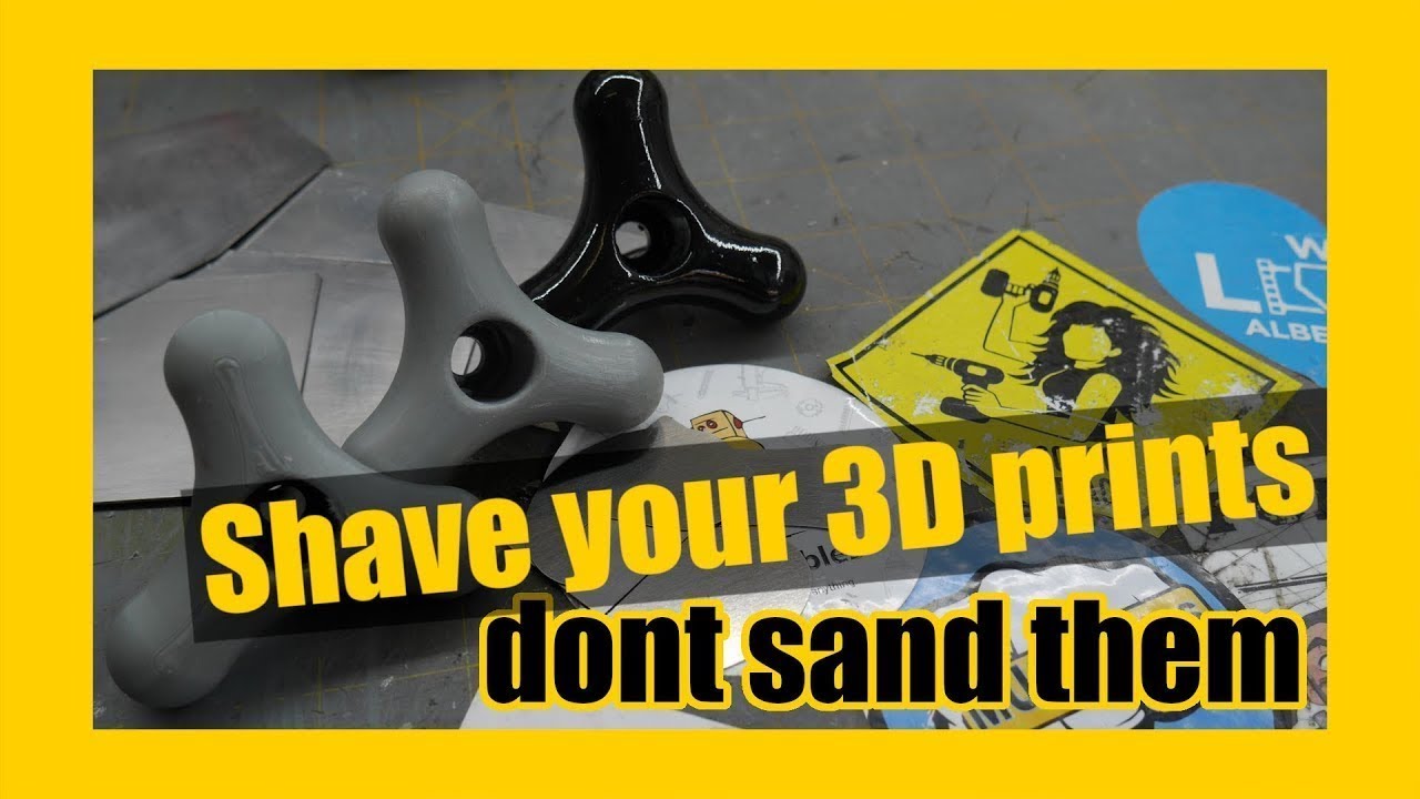
New video: How to make custom scrapers! https://youtu.be/TbvFPN7yxt0 Spending time sanding 3d prints is a thing of the past. Reduce your time prepping prints for paint or just prepping them by using card (or cabinet) scrapers! These little guys can quarter your time prepping 3d prints. Period.
00:00 Introduction
00:55 Card scrapers
01:47 The ...
nova minnow
so im making a straw that you can slot into itself
properly
perfect size for any drink container
faint sky
I make big stuff and these are really handy.
 faint sky
interesting
nova minnow

yes i noticed a design flaw
that hole you see on the bottom right
wont be there soon
imma just extrude it cause i dont need clearance there
faint sky
getting the infill out of that channel will be challenging.
i mean support material not infill
nova minnow
first thing i do is try printing it without supports
if it breaks then i add them
it seems like it should be fine
in fairness
to make it easier to print i sloped it kinda
so its not like a solid overhang
it kinda builds itself up as it goes
shy kelp
faint sky
I make big stuff and these are really handy.
You can even put it in the oven with grainy stuff like salt
I wonder if you can get decent effect with a brush and a power tool
A lot of microplastics...
faint sky
Sometimes you can print on air but I wouldn't count on it. If you want to ensure you can do the channel without supports then make the walls 45 degrees between the parts.
balmy pulsar
nova minnow
will it leave a hole or no?
usually you will see a small over extrusion bump from transitions. no bid deal.
nova minnow
i'll probably just bend some sheet metal if i have to
put that in there
break the support out
it'll be fine
shy kelp
There are also arc overhangs
nova minnow
i hope it prints without supports because the whole idea is to use as little plastic as possible

faint sky
I have a 90 degree pick tool that would be good at something like that.
nova minnow
it's supposed to be a recycled thing
shy kelp
nova minnow
i hope it prints without supports because the whole idea is to use as little pla...
You may use the "lighting" infill with a thick shell then
shy kelp
Or just slice it in two
balmy pulsar
shy kelp
You can even put it in the oven with grainy stuff like salt
I wonder if you can ...
the salt thing is basically a recast. You are effectively making a cast part using the original part as the pattern and salt as the mold.
faint sky
Pick tool set can come in handy for getting hard to reach support material out.
 nova minnow
oh i have them already
balmy pulsar
teeeny long nose and curved pliers too
 faint sky
i meant the channel on the first part you showed
nova minnow
im doing it at 0.08mm cause its supposed to be water tight
weather it will be or not is a separate question
balmy pulsar
youll never get water tight on a print. ive tried
well, not "never" but i wouldnt rely on it
faint sky
that's a very fine setting. keep an eye on it for excess buildup around the nozzle.
nova minnow
faint sky
that's a very fine setting. keep an eye on it for excess buildup around the noz...
tyty
nova minnow
balmy pulsar
youll never get water tight on a print. ive tried
dw it's less of a water tight test rn more of a does the design work
test
balmy pulsar
what is the nozzle?
nova minnow
i'll worry about the water tight part when i get to it
nova minnow
balmy pulsar
what is the nozzle?
0.2
faint sky
yeah might be possible with flow rate adjustment, i've never gone below 0.12
balmy pulsar
ive done a lot of 0.15mm layers with a 0.3mm nozzle. it clogs a LOT
faint sky
yup that's another concern, very likely to clog
balmy pulsar
it does work, but id say every 2nd small print is a fail
faint sky
there are smaller nozzle sizes for finer detail but i don't have an personal experience with them.
building a 0.08 profile sounds like a challenge
balmy pulsar
i have some 0.2mm in a box. ive gone full on the other way though, i like 0.8mm nozzles now.
for building larger structural parts fast
faint sky
same
for industrial boxes, enclosures, etc.. I'll take function over form. The .8 nozzle puts down some thick lines.
nova minnow
i have a superstition about my printer
if i dont listen to money for nothing whilst it prints
it always fails
every time
when i put it on
it comes out perfect
every single time
faint sky
lol they all have their own personalities for sure. keep it happy and it will keep you happy.
nova minnow
yes
my printer just loves Dire Straits
i mean the start of money for nothing is 100% what makes it print right
just the best intro ever
after them asking for their MTV
yk the bit
balmy pulsar
i feed mine cookies. and pizza.
nova minnow
balmy pulsar
i feed mine cookies. and pizza.
wooooooooo
shy kelp
I am using my k1 as shoe drier
It never ends to clog
Literally my 10 year old ctc i3 wood gives me less problems
As they say when you go cheap you end up spending more huh

 acoustic quiver
Hi there, I can create a thread for this issue (as it may get a little extensive lol) but, I am using an ELEGOO Neptune 4 Pro, trying to do some Pressure Advance calibration using the Pressure Advance Tower test built-in to OrcaSlicer and running into some issues, I can specify further but I just want to gauge first if anyone has experience with that or may be able to help, thanks in advance! 🙂
I am dealing with underextrusion in the corners of the test print. A theory is that the firmware is not respecting Pressure Advance changes via G-Code

Sorry if the quality isn't great, but you can see that in the back corners light is clearly passing through, and in the front corners there is definite underextrusion and stringyness
I am probably going to run a test following the Klipper Documentation rather than the test built in to OrcaSlicer, and see if maybe I have some settings wrong, or missing a step or something. I will update with how that goes, but any input or recommendations would still be greatly appreciated!
acoustic quiver
I am currently running the test with the provided STL from the Klipper documentation. The corners look much sharper so here's to hoping this test works. I am wondering if maybe I am supposed to issue the TUNING_TOWER_COMMAND stuff or whatever, but am unsure because I'm pretty sure I ran this same test a couple weeks ago with the built-in OrcaSlicer test without issuing any commands and the corners came out fine back then.
I am unsure as to what the issue could be there, and can only hope I didn't mess up a setting somewhere and don't realize lol. As far as I know the only things I have changed are printing temp, Flow Rate, Rotation Distance, and that should be it
 inland galleon
any 3d modelers around? trying to figure out how best to 'fold' the highlighted face down into the flat part of the back

this is in f360. i can do basic squarish things ok but this is by far the fanciest thing ive ever tried to model, and its been stalled for like 2 years ^^;
this is loft (with some fillets, and im not in love with it
 balmy pulsar
loft needs a gap for best performance. split the object and leave some space between and loft the gap. use the guide tools to make sure is is straight. Also, dont mate round to sharp corners with a loft. Add a small fillet to the top edges of the second part.
inland galleon
ill def try the fillet, but im not sure what you mean by the gap
you mean split the obect at the part im trying to merge (vertically) and put a small gap between them?
balmy pulsar
nope
split on the face selected in the first image
then make a gap between thr 2 parts
 split raven
For people using CAD for 3d printing, do you try to use dimensions that are multiples of layer height / extrusion width? Does it matter? I assume that the slicer will round up / down values so if you want more control / accuracy you might as well take those into account when designing?
vocal flax
shy kelp
I am using my k1 as shoe drier
It never ends to clog
Literally my 10 year old ct...
I think there are 2 reasons for this. The design was robust, and repeatable. And back then availability of low quality components were low. I'm sure they were present but I assume the price cut wasn't worth the supply chain complications.
vocal flax
inland galleon
This is probably best resolved using surface tools. as far as I understand you want to "extend the surface then stitch with other surfaces to create solid".
vocal flax
split raven
For people using CAD for 3d printing, do you try to use dimensions that are mult...
Layer height/extrusion width yes. Depends but most likely not. Slicer might do some stuff, depending on settings. Arachne setting in prusa slicer may vary line width to match dimension or slicers do some filling movements for small gaps similar to ironing.
shy kelp
split raven
For people using CAD for 3d printing, do you try to use dimensions that are mult...
No? I just use some random precision table online by material, and scale by that value. Or print some dummies to have a real world value
faint sky
I don't scale at all with my models. I attempt to get them accurately represented to the thousandth of a mm. I do not take into account what the layer height or any other slicer settings will be. Doing so is pointless unless you want to make a model for every nozzle size and setting. The models are what they are, and the slicer has to compensate for that not the other way around. Are there advantages to doing it the way you mention? Well yes but will take up so much more of your time that's its not worth the effort.
balmy pulsar
you will need to scale if you intend to match any pre existing object. the material shrinks unevenly. for pla i often have x and y set to 105%. z tends not to shrink significantly due to the nature of the way it prints.
faint sky
I suppose if you're going to make a model of something that won't fit on a print bed like a full sized car then yes scaling will be required. For shrinkage I do those adjustments in the slicer.
split raven
Interesting responses, thanks. I didn't think about compensation for shrinkage. That's the kind of thing I would expect the slicer to do
balmy pulsar
faint sky
I suppose if you're going to make a model of something that won't fit on a print...
i mean scaling in the slicer....
you dont tamper with the cad model of course
split raven
Do you do scaling in the slicer in addition to adding some clearances in the CAD design?
inland galleon
vocal flax
This is probably best resolved using surface tools. as far as I understand you w...
thanks. looks like i have a new tool to learn
balmy pulsar
split raven
Do you do scaling in the slicer in addition to adding some clearances in the CAD...
clearances you would do in cad if needed. scaling in the slicer is just to get the output to "match" the cad as close as possible (its never perfect)
inland galleon
i only worry about layer size if im making something thin. if its going to be like 1.5mm+ i figure im fine with the error margin
shy kelp
Has someone ever tried to print some cage nuts?
Didn't found them in the hardware store, I've got standard nuts which work fine, I don't have time to do some testing so I was hoping to find some already made model
It's easy, but I don't trust too much the plastic wings
faint sky
Haven't tried it but seems about the right shape. https://www.thingiverse.com/thing:5248527
shy kelp
Not really the case, it's for a rack, I ended up designing some crap without knowing the exact holemount (although it has some tolerance)
Let's see how it goes tomorrow with 4/5 hours of sleep yuk
 leaden slate
I am printing one of these
https://www.printables.com/model/41018-microphone-voucher-box-mikrofon-gutscheinbox
the head is 2 pieces and im going to print it out of conductive pla so it can be a capacitive touch object. Do I need to do anything special when i put the 2 halves together? The wire will be connected to the bottom half, I am concerned that if I use some super glue that the top half wont work
https://media.printables.com/media/prints/41018/images/406494_58751cba-ec3f-4572-b2c3-b669781c9d98/thumbs/inside/1600x1200/jpg/head.webp

Printables.com
Ein Mikrofon mit Ständer und abschraubbarem Kopf zum Verschenken von Eventgutscheinen. | Download free 3D printable STL models
 faint sky
could redesign it so it's snap fit
or put large metal scissor springs that make contact with the inner shell once put together.
leaden slate
that makes sense. my skills are limited to openscad. I added a couple holes to the stl for the clip for the bottom half, maybe I could add more holes and a peg to hold them together, the only downside is it took a long time to render
 leaden slate
There's also nothing stopping me from putting a screw into it
faint sky
coat the inside with aluminum foil then make a big ball of foil to fit in there. it's bound to make contact that way too.
i mean there are about 100 different ways to skin that cat
 ornate imp
is there a reasonable and sane way to split a mesh for a print in half or am I going to have to keep fighting blender 
vivid helm
ornate imp
is there a reasonable and sane way to split a mesh for a print in half or am I g...
PrusaSlicer has a tool for that.
ornate imp
seems if I had use mirror modified on a mesh, applied it, did other work, and then try to bisect it fails to bisect properly on one of the sides
ornate imp
vivid helm
PrusaSlicer has a tool for that.
can it export back to stl? I normally use cura, not sure how programs etc differ
still kind of an amateur with 3d printing and 3d modeling in general makes me irate
vivid helm
ornate imp
can it export back to stl? I normally use cura, not sure how programs etc differ
Yeah, if you right click you can export.
ornate imp
I'll give that a try, thanks. Blender refuses to slice this properly and I can't figure it out
and this is all just so I can make sure this helmet frame I'm creating is the right size, but it's slightly too big for my ender's bed
vivid helm
ornate imp
I'll give that a try, thanks. Blender refuses to slice this properly and I can't...
It could be that your model is screwy.
Some models are like that.
ornate imp
considering I'm trying to print a wireframe of my original model that's also possible, but it's incorrectly splitting on exactly one half of where I had it mirrored
really annoying
 faint sky
I don't use Blender, what I'd do in Fusion 360 is make a flat plane to cut the two sections in half. Then delete the plane.
Technically I would extrude the plane negatively so there is no plane but that's the basic principle. No idea if that'll help in Blender.
ornate imp
Bisect is a mesh splitting tool that does the process you're explaining, but the actual mesh separation afterward is breaking due to the mirrored mesh state or something, even after applying the modifier so t hat it's just a raw mesh before bisecting and it still does this
Every time I use blender I have to re-learn how to do the most basic things and anything that's not just doing an extrusion or something ultra-simple is outdated info or breaks in weird ways, I've never enjoyed do any 3d modeling at all so I just hate it every time 
20 years of repeatedly going back to do any basic 3d modeling and it drives me insane every single time
Generally I believe people are capable of doing anything if they apply themselves enough but 3d modeling is one thing I cannot do adequately, ever.
faint sky
If it's mirrored and you're deleting the original side of the mirror then it should change the other half. In theory. Your idea is sound, no idea why that's not working.
ornate imp
The weird part is those attached vertices on the center-to-right, are the original non-mirrored portion that I had before it was mirrored
which makes it even weirder
faint sky
oh it tedious for sure and there's always a learning curve.
ornate imp
yikes
okay, I have no idea how I'm going to adequately test the proportion of this without burning through entire spools
I thought going wireframe would reduce the filament but then I need even more supports, so just one half is 600g 
faint sky
there isn't a measuring tool of some kind? so you can scale it the correct dimensions?
ornate imp
I can 1000% guarantee you I cannot properly measure the size of my head for this model
that's why I want to do a basic 'shape' print to test the proportions
faint sky
lol, youtube videos. there's a video out there somewhere.
looks like bisect mode is what you want
ornate imp
well I split in half in prusa but the filament cost is too much for me right now
I'll figure out something eventually, just a lot of things for my project are oriented around framing this helmet correctly
faint sky
😦
ornate imp

faint sky

A quick demonstration of the Bisect Tool
Fine me here on Twitter: https://twitter.com/IdoineTutorials
Gumroad Membership & Downloads : https://gumroad.com/onlinerender
#blender #tutorial #bisec
ornate imp
just going to print the original model not this wireframe one, still have to use prusa to slice though since blender is being dumb
haven't done a print longer than 8 hours before so this'll be an experience 
thank you for looking though, I think it's just an actual bug in blender or some kind of extra situational knowledge we're not aware of
my very much WIP project is being shaped by this

 worldly comet
Hi. I like my Ender 3, but now I want auto bed leveling and two colors at a time. Suggestions?
faint sky
Sovol SV04 is an IDEX (independent dual extruder) setup. Sovol is a Creality clone that uses mostly Creality components. That would be the cheapest entry level for an IDEX. Then there is of course the Prusa MK4 with MMU3 addon or a quite pricey Bambu with AMS.
There are also some mods available for the Ender 3 to make it an IDEX if you're not wary of tinkering with your setup.
worldly comet
faint sky
There are also some mods available for the Ender 3 to make it an IDEX if you're ...
Thanks!
ornate imp
Not surprised but the first half of my helmet 3d print cracked at layer lines when removing it from the baseplate; I semi-melted those portions back using a heatgun, though kind of overheated and damaged it, but I'm mostly testing size/shape as a very rough print so I'm not upset about that.
I printed with standard PLA (not PLA+), 'low quality' 0.28mm layer thickness, 20% infill and the reason I did that is to speed up the printing time while reducing filament usage - although apparently using a thinner layer line with more infill would've used a lot less supports and thus less filament, but I saved 10 hours off half of this entire model in print time.
As I continue working on iterations of it toward the final goal I'm probably going to use 100% infill, thinner layer lines, and might look into PLA+ or another filament type.
Curious if anyone has some suggestions on how I can ensure it can be kept sturdy in case something bumps into it that it doesn't split along the filament line, including potential post-processing (which I may end up doing on final result with sanding/painting/etc).
faint sky
I wouldn't waste money on PLA+. Either use PLA for indoor projects or PETG for outdoor projects. PLA+ is an attempt at a hybrid and falls short of its intended use.
If you're going to print hotter with PLA+ might as well print with PETG anyway.
ornate imp
So far I've only used PLA filament, and this probably wouldn't be used outdoors much at all if ever
I'm just concerned about strength of the print's resistence to impacts/falls/etc so it doesn't split open, but again it's probably infill and layer thickness that should solve that
shy kelp
ornate imp
I'm just concerned about strength of the print's resistence to impacts/falls/etc...
Indeed, or another way may make a more or less void shell (use lighting infill), and then infill the inside with some other material, like any cheap construction potty, but it won't be light
You may also want to use some infill combination to save time while not having bad resisted
In the bambuslicer it doesn't seem to he there, but in some others it was... You could replicate in cad anyway
Or maybe make an outside coat of resin
Or then use the 3d print thing, as a base for sturdier materials
ornate imp
given it's a helmet for an XR wearable project I'm working on, the lighter I can make it the better, because I've also got electronics, wiring, and batteries to fit in as well.
I'll also have to ensure it is breathable so it'll probably have some vents here and there which will weaken the structure but also make it harder to just 'cover it' it with another material, but this type of design work is new to me
I'm probably going to be dealing with 5-10 iterations of this before it's even close to what I want. this first print was just a size test print for the initial structure so I can get an idea IRL if it fits on my head, what parts I need to give more room for, etc befoer I work on the actual model more
it's 2.7mm thick so it's not all that big, I'm just concerned about it splitting too easily even when I use 100% infill or once I make more structurally weak sections
and I don't want to spend hundreds on filament trying to figure this out if I can since a single print attempt costs me $10+ in material
shy kelp
ornate imp
and I don't want to spend hundreds on filament trying to figure this out if I ca...
Make a aeries of smaller copies then
Or just one and call it a day
Or use it as a base for other materials like paper and vinavil
ornate imp
if I had 500x more experience as a 3d modeler (because I have effectively none) I'd consider 'just one' as a possibility, but that's not possible heh
shy kelp
ornate imp
if I had 500x more experience as a 3d modeler (because I have effectively none) ...
It needs to fit your face? You could easily replicate with a couble of photos
Or maybe 3d scan your face through photogrammetry and use that, but likely you'll have an heavy mesh that you need to retopo (I am bad with it, I can't help much more)
ornate imp
Fitting my face is the reason I'm doing this initial print to get a size gauge, and I'm almost done printing
I already tried using a premade high quality model and trying to edit it was extremely futile. ignoring retopology I couldn't seem to edit anything without severely breaking the mesh
my concern is making sure I'm not spending dozens/hundreds of hours trying to make a model that inevitable just won't even work if it's never going to be structurally strong enough to do this project
I'm newer to 3d printing and absolutely new to making wearable structures for a project, but this isn't just a cosplay thing to wear once or twice, I'm making a custom XR headset that is going to be used quite a lot
shy kelp
Yet another option is going full "analogic" get a negative of your face through life casting using like silicone (not sure, google that, I haven't done anything since I was in art highschool)
shy kelp
I mean you should try what works or you could cold consider to pay someone else to do the job for you
But unless you're getting someone from a lower income country, it won't be cheap either way
ornate imp
Yeah I'm not paying someone else to do this, I'll just have to brute force this on my own.
Because it's a low-poly model I can very easily measure offsets needed from this first print off the flat quad sides, and then make adjustments from there in my mesh.

This is the cracks it had, and then it looks funny because I tried using heatgun to re-attach it lol
that's just the back half, and so far I can tell it fits my head well. front half is finishing tonight
once this finishes and I get a feel for the sizing while figuring out offsets needed, places to put my electronics etc, then I can do a more thorough quality print which hopefully won't crack like that
currently takes 500-600g of filament for one iteration to print and I don't expect that to change more than +/- 50g
faint sky
Use a soldering iron to remelt pieces together. Theres a knife attachment for most soldering irons or plastic welders that is specifically for that kind of thing.
ornate imp
Y'know, when I got my soldering iron + heatgun station it came with about a dozen tips and I've really only used one so far.
faint sky
Cracking apart means the shell is too thin. But you also dont want to waste a ton of filament for thicker prototypes.
ornate imp
I wondered if the knife-tip was just some kind of weird multi-pin desoldering tool instead
faint sky
It is but also works great for plastic welding.
ornate imp
The shell is too thin in general (2.7mm)? Or would having thinner layer lines be better? Or both, heh
faint sky
Just ensure to clean the tip well after use so you can solder with it later. Wet sponge does well.
ornate imp
Yeah I have sponge and brass wool
brass wool for the solder ofc
I wouldn't want melted plastic in that
faint sky
Yup i use my soldering iron on both electronics and 3D prints. As long as you clean it well its a dual purpose tool.
ornate imp
speaking of soldering iron and 3d prints, I should print a case for my pinecil I just got
faint sky
Shell is just too thin if walls are 3mm. I make beefy 5-10mm thick parts. They’re more prone to warping than cracking. You’d need a baseball bat to crack it.
ornate imp
Any process for the final design to be uh... cooked? Obviously a bad idea to put it in your home oven, but something to that effect that could cure the layers a bit more
faint sky
But i wouldn’t want to do prototypes thicker than 5mm. Thats a lot of filament for a helmet sized project.
ornate imp
Or maybe some kind of primer sprayed on
Yeah, I just did a basic modifier to the model to give it volume and printed that to see what would happen. I physically measured the print afterward, heh
faint sky
If you more strength for a helmet just brush on some clear epoxy resin.
You can add fiberglass to the outside, even kevlar, and epoxy that.
Of course sanding and painting too.
I built an entire 16 ft boat using that method. If you want a strong helmet that’ll do it.
ornate imp
The worst case scenario I can imagine is it falling to the ground in terms of impact
I probably don't need it to survive a baseball bat, but that would be a neat bonus 
balmy pulsar
new toy. (well, old toy, but being heavily modified)

this is what it used to look like.

basically i am making it smaller.
balmy pulsar
the motor is on the top there. 500w ac servo.
86mm square.
and yeah, its heavy, 500lbs fully built.
haha
ornate imp
@faint sky second half cracked when I removed it despite trying to be gentle, but the knife soldering tip trick helped seal it 'enough', ty
ornate imp
I ended up welding them together using it too
worldly comet
Hi. I’m setting up a new SV04. I turn it on and do a 'home' and the right extruder moves to the right and tries to keep going after it hits the limit. Could it be because the metal piece is bent? I really don’t want to disassemble and pack this thing and send it back.
 faint sky
Does it have a limit switch on that side? Malfunctioning limit switches are a common issue for a printer not homing correctly. Also possible if there is a limit switch that it wasn't installed 100% correctly. No the metal bend shouldn't be a problem that I can see.
worldly comet
I used a wrench to straighten the bent blue metal piece, and that allows the part to slip into the limit switch. So that problem is solved.
faint sky
I stand corrected. It didn't look that bad but if it required a slot to fit the limit switch trigger yes that would be an issue.
misty ibex
So close to getting my new office setup and getting my 3d printer settings tweaked. I'll be asking for a lot of help here....
shy kelp
On the bambu slicer, do I have no way to use a svg or the kind to introduce patterns on the outside shell?
hollow blade
hey guys I found something to 3d print at a shop but have a problem
are the dimensions already predefined
faint sky
with an stl yes the dimensions are predefined, no scaling should be necessary
 pseudo isle
does anyone have CNC machine that might want a little side work?
balmy pulsar
depends what the work is
I am in xmas gift mode https://www.youtube.com/watch?v=pSjNn7hZf3g

In the category of "things you should not be doing on a mini router, but reaaaaaly want to". :)
This is the long form video showing the process of machining a steel keyfob. Off camera I did an epoxy "enamel" fill in red and black. Epoxy is not enamel sadly, so it did not level out to a thick glossy finish. Instead we will wait til it cures and ...
next up, wood magnetic knife blocks
pseudo isle
what i need is acrylic cut into a circle
balmy pulsar
ah, no. acrylic is better done with a laser.
milling it has a tendency to make cracks
 bleak flare
@pseudo isle there are quite a few cut to order shops on Etsy that will allow you to upload a shape and then they laser cut it
 toxic plover
My ender 3 pro has a tendency to not extrude properly, its been happening ever since I added this sharpie mount. I removed it since, but still doesn't. I replaced the tip, tried leveling, and cleaning the hotend but no luck
 vocal flax
toxic plover
My ender 3 pro has a tendency to not extrude properly, its been happening ever s...
vocal flax
toxic plover
My ender 3 pro has a tendency to not extrude properly, its been happening ever s...
Have you reseated/changed PTFE tube. I've heard PTFE tubes can cause under extrusion.
Cleaning extruder gears is also an easy option. Can be checked off easy if not done in a while
faint sky
define not extruding properly?
under extruding, over extruding, inconsistent extruding with gaps?
PTFE tubes on a bowden setup are considered consumables. They will eventually degrade near the end, get crusty, and particles can break off causing clogs and inconsistencies. Partial clogs can be a pain to track down because it usually involves tearing down your hotend assembly up to the extruder gear to find the issue even on a direct drive system.
vivid helm
I just had to do that recently
faint sky
With direct drives the most common cause for clogs is too close of a z-offset and too fine of a layer height. Backpressure will cause clogs faster than a physical defect.
yeah it's not fun but necessary maintenance occassionally. extruder gears can wear down so have to check those for proper operation and wear too.
calibrating e-steps is part of that. whenever you have to disassemble the print head assembly then you have to recalibrate everything again. just goes with the territory of being a 3d printer owner.
and there's the possibility of your nozzle literally unscrewing itself due to friction on layer lines. that has been a continual issue on my Ender 3 S1 Pro. i've figured out that's a major reason people wake up to their entire print head assembly being covered in a gigantic blob. if it unscrews even a little filament will start oozing out the size of the nozzle where it screws in instead of the from the tip.
if you start getting excess buildup on the sides above the sock good chance the nozzle has unscrewed a little.
and the main culprit for that really is over extrusion and incorrect flow rate or esteps
toxic plover
vocal flax
Have you reseated/changed PTFE tube. I've heard PTFE tubes can cause under extru...
That's the next thing I'll try
toxic plover
faint sky
under extruding, over extruding, inconsistent extruding with gaps?
Very thin lines and occasional blobs
faint sky
yup partial clog or too much back pressure
toxic plover
Ight I'll see if I can fix it
 hardy inlet
Could any one enlighten me about why my print turned out like this,
Is it a clog or not dry filament or something else?
Any help would be appreciated
 balmy pulsar
clog or slipping extruser
toxic plover
hardy inlet
Could any one enlighten me about why my print turned out like this,
Is it a clo...
Yea basically mine if they even get that far
hardy inlet
balmy pulsar
clog or slipping extruser
Thanks for the help, I heated it up a little and pulled out a long thin filament and it seems good now
hardy inlet
toxic plover
Yea basically mine if they even get that far
That's unfortunate, I hope you resolve the issue
balmy pulsar
clogs are annoying. ive had some filaments like matte PLA that are really prone to clogging
i guess cause it literally has sand in it
coarse coral

 ocean orbit
yes that looks less than ideal
coarse coral
Terrible. Impossible to recrimp
I could solder it at risk of melting the plastic
I feel solder is the best thing
Or do I just snip the block and try to crimp


There was absolutely no reason for me to disassemble this thing just to move house
coarse coral
I need a new filament holder this one maxes out at the ceiling (not something you hear every day) and also need to model a holder so that the LCD can rotate 90
Not sure what I feel about this. Yes it's a sort of ready made enclosure but it just seems somewhat restricted. Lowering the shelf is probably the smartest move
coarse coral
coarse coral
Yeh this has been cancelled
coarse coral
Yeh the printer was taking a q and a and got most of the answers factually accurate. The host decided that wasn't good enough, so yes. Cancelled.
vocal flax
coarse coral
I need a new filament holder this one maxes out at the ceiling (not something yo...
Why not reverse bowden and tush type of spool holder
coarse coral
vocal flax
Why not reverse bowden and tush type of spool holder
It's too high either way, I will struggle to remove the build plate at the only orientation it fits. I'll probably come up with a shelf in some other location of which none are apparent to me yet
Was considering up high there but that space is too valuable for media and consoles
 faint sky
Don't place it so high that you have issue reaching to swap out filament rolls.
Some type of square stand would go well there. Maybe something with cabinets to store spools and tools in. The one thing most people don't account for is where all those boxes of spools will go.
shy kelp
Did I f my tip? The back stuff is melted petg
 vocal flax
Nah if you use brass (or something soft and heat resistant) to clean it off when it's not it should be fine
balmy pulsar
petg will always build up on the nozzle. you need to just keep cleaning it off. sometimes several times per print
main thing is to keep it from hitting the print if it builds up a lot
faint sky
While it's hot rotate a wet sponge around it and that helps a lot. Then the brass sponge helps take off the rest and will get it back to a nice clean tip you can add solder to.
balmy pulsar
most printers come with long tweezer sets. this is what they are for
faint sky
Once it cools down you can scrape most of the filament off with a fingernail too. Doesn't all have to be cleaned up while it's hot.
like if you intenionally leave a chunk on there when it cools it'll pop right off.
balmy pulsar
i find when it is cold petg is bonded on. not gonne ever come off.
coarse coral
faint sky
Some type of square stand would go well there. Maybe something with cabinets to ...
Thanks @faint sky Yeh I have 3 wall storage wardrobes from floor to ceiling. I really want one of those to be freed up for all project work.
One currently is storage for golf clubs and decorating things for my place. The other is overflow storage which could be re organised a little bit and the other acts as a closet. I think the second will need to be overflow and closet and free up the last.
The last wall closet should ultimately be the 3d printer at a height that's practical with storage under for filament and all my electronics tools and project thingies.
I considered getting rid of my desktop pc and going to a laptop recently but I doubt thats going to happen. I don't want to feel like I'm not in the pc master race any more
I'll probably just buy some off cuts of wood and make a shelf. Then add storage to that over time.
But then again I just measured and for correct orientation I need 76cm deep and sadly all I have is 60. Closets are not an option now and where the previous photo shows that's not an option either as it leaks into the walking area.
The only other obvious place is table mounted next to a radiator which is bad for many reasons. There's actually no place that I can see 🙈
It's probably going to be going in horizontal on a shelf to wall closet number 2.

When Ur 3d printer is bigger than Ur house
faint sky
If your 3D printer is bigger than your house then you just print new additions to the house. Wouldn't that be nice.
coarse coral
Clever idea. I'm on it
shy kelp
faint sky
If your 3D printer is bigger than your house then you just print new additions t...
Not going to be legal though
You know you should first pay tons of licensing first
coarse coral
Print closet version 1. Codename: Creally Squashy C1
I measured this to a height that was optimal, and also identified places of the walls to drill into. Ultimately I ended up putting off cuts atop offcuts in order to get the right structural integrity. This is engineering (not) at it's finest
coarse coral
Definitely going to find a more solid piece of wood for the shelf itself or maybe some aluminium. That's so janky
 sudden lion
Looks like I wrecked this end stop switch, ordered a new one

While I'm at it I should probably clean up the dust
faint sky
Yup that's what it looks like when the silver trigger tab breaks. :/ I got a pack of cheap ones from Amazon but only about 1 in 10 actually worked correctly. Test the switch continuity to make sure it works before going through the trouble of installing it.
vocal flax
If it still presses its better to not use the little metal part. It improves repeatability and it doesn't catch random stuff.
Overall more robust
faint sky
if you can get it to reliably press in the same spot... that one looks pretty borked.
sudden lion
Yes it's not able to press it because it's broken out of place
 reef sapphire
sudden lion
Looks like I wrecked this end stop switch, ordered a new one
reef sapphire
sudden lion
Looks like I wrecked this end stop switch, ordered a new one
same happened to me but if you have the metal bracket just put ut back itll work
sudden lion
reef sapphire
same happened to me but if you have the metal bracket just put ut back itll work
It somehow got bent/moved to where it's no longer laying on it's side, I am not sure the proper way to move it back or if it's fixable. I'm not very mechanically/electronicy inclined. I'm afraid I might break something. I'm just a hobbyist but I know someone who is an expert on this kind of stuff
It looks like it's lifted off the PCB
faint sky
The limit switch was directly soldered to a PCB? Usually they're screwed down into a mounting location. That does not look easy to access. What are the chances you can contact the manufacturer for advice or warranty?
vocal flax
That looks like MakerBot limit switch clone those aren't screwed in neither has screw holes exposed (PCB covers)
It's just the metal legs bent if you fold it over how it was or to a place where itd press (assuming it doesn't spring back) it could work.
Additionally if you're handy you can just scrap the whole board and make switch holder and manually wire it
balmy pulsar
just pay $3 and get some omron limit switches 😛
hardy inlet
I was 3d printing today and my first layer had a skip in this section. It looks like the nozzle still went through the entire section but the filament did not come out. By the time I saw it, it was already done with the first layer and the rest of the print went fine.
Do I need a new stepper motor for this or is this a different problem?
Any help is appreciated!
 ocean orbit
i would keep an eye out for a repeat of the issue
coarse coral
Yeh keep an eye, it might be just your nozzle or tube had a bit of a clog. I'd replace nozzle and tube (or at least snip) if it continues to happen. Also I've found that Bowden's are naturally lubricated with the material they are made of and some times it becomes somewhat abrasive leading to chatter in the flow. In the past I've replaced the tube and the chatter goes away
shy kelp
No luck to find some kind of spring constant/topology sheet between different materials, or do I necessarily need to waste material into some testing?
ocean orbit
a 3d printed objects properties will depend on how its printed so you would probably need to do testing anyway, depends what you are doing though
balmy pulsar
yeah, a solid pla or abs spec sheet is kinda meaningless
shy kelp
Ehm outside of pcbway, there ain't any cheap metal cnc manufacturer?
balmy pulsar
jlcpcb has it too
i think
Instant online PCB quote, get PCBs for only $2. Check design with the online gerber viewer, Easy and quick PCB Price Calculator from JLCPCB
more limited options. just aluminium and plastic and copper
i think jlc does in in house though and pcbway aggregates verndors
faint sky
Send Cut Send comes to mind, if you want sheet metal laser or water jet cut and formed. Depends on your design needs. Actual CNC from a PCB manufacturer doesn't sound like a bad way to go if you want a metal casting mold or something like that.
balmy pulsar
cnc is not one button. thats the main issue with the services. you need to be super clear what you want and to what tolerance. every decimal place in tolerance can add 2 zeros to the price
ocean orbit
considering hte amount of times i mess up my 3d prints i would be terrified of ordering lol
balmy pulsar
i have a friend for big stuff or precision stuff i cant do. i trust him to make sense of what i am asking.
maybe i could save 20% with pcbway but... not really worth my effort
we have a colour code system. blue is "inimportant", yeloow within 0.005", green 0.001", and red is "as good as you can possibly do"
so i just colour all the surfaces in fusion
faint sky
I think the point was for people who don't have a friend with a CNC and/or don't want to pay an arm & leg for a small personal project for a one-off. The whole point of 3D printing is being able to design & produce small parts for hobby use.
balmy pulsar
well no, the point of 3d printing is to make things that are otherwise difficult or impossible to make any other way and to make functional models quickly. it has adapted for hubby use very nicely because it is becoming more and more of a one button solution. CNC is still complicated and somewhat expensive whether you do it yourself or send it out.
anyhow. cnc service form pcbway and jlc seem quite organised, but it will all hinge on communication.
ive used JLC for metal prints, and they communicate issues very well
vivid helm
Safety is another major consideration. Also power.
hardy inlet
On the right is the first layer of the print and on the left is the rest of the print, there seems to be some extrusion issues with the infill. Does anyone know the solution to this problem? I just cleaned out my nozzle and Bowden tube. I'm starting to think it is my extruder stepper motors fault.
 shy kelp
balmy pulsar
well no, the point of 3d printing is to make things that are otherwise difficult...
shy kelp
balmy pulsar
well no, the point of 3d printing is to make things that are otherwise difficult...
It's also incredibly loud, I can't have that equipment at home even if I had the money
I kinda regret refusing a job into a factory that did manufacturer machineries to print on metal, but I guess that from now on I am banned from working there since I refused the job like a week prior the start date lmao
shy kelp
hardy inlet
On the right is the first layer of the print and on the left is the rest of the ...
I may be wrong, but to me, it seems that you have some leveling issues or filament that bubbles
hardy inlet
shy kelp
I may be wrong, but to me, it seems that you have some leveling issues or filame...
Thanks for the advice, I was dumb when cleaning and messed up my Bowden tube so I trimmed it and when reinstalling I didn't have it touching the nozzle which caused the issue and a lot of clogging.
It's printing fine now but I only have half my bed to use since the Bowden tube is shorter now, just waiting on the replacement to come in
shy kelp
Any cheap 3d scanner (like 200? Or more, but the less the better), that makes up usable meshes?
Photogrammetry is a pain and expensive
Random things that I find on the net, are like limited in object size, having a turntable table
balmy pulsar
200... 000? yes.
:x
i think creality has one for $600. thats one of the cheapest i know of
ocean orbit
Im going to go with probably not for anywhere close to that price
Theres the openscan but its certainly more than 200 and very limited in object size, what kind of thing did you want to scan? Someone might have an idea
 verbal sail
shy kelp
Ehm outside of pcbway, there ain't any cheap metal cnc manufacturer?
verbal sail
shy kelp
Ehm outside of pcbway, there ain't any cheap metal cnc manufacturer?
What are you looking to have done? I built a small lathe and may be able to help
ocean orbit
I would love a lathe and other tools, sadly tiny apartment 😦
balmy pulsar
my lathe was destroyed in a flood, but i cleaned it up a little and sold it to the university of guelph race car team. should be interesting ha
verbal sail
ocean orbit
I would love a lathe and other tools, sadly tiny apartment 😦
Build one. Some extrusions, brackets, and a grinder/ hobby saw and you have a basic lathe that turns aluminum well and fits on a desk
ocean orbit
oh for sure but i have no space sadly, nevermind though!
balmy pulsar
grinder i think is way too fast. but the principle is sound. especially since the "cheap" mini lathes are now almost $2000
verbal sail
This was an early version of what I have. I made some alterations since then to make it more stable. It has variable speed as well. Fun part is, I used the grinder to build the lathe
 ocean orbit
That is cool, amazing what you can do with a bit of ingenuity
verbal sail
I'm going to be redoing the instructions for the build if yall want it
ocean orbit
I couldnt use it but im sure some will be able to

 verbal sail
I'm gonna be adding a mill section to it as soon as I figure out how and can afford it
balmy pulsar
mill is harder, because it needs so much rigidity and precision.
verbal sail
Yeah. I'm thinking I may have to add an extrusion cube with cross beams. Take some inspiration from architecture and construction
balmy pulsar
i am trying to put this one together economically. it is not really turning out to be worth while for me though. i can buy a better/bigger one for less time and money. :/

"real" used cncs are so cheap now too. if you have any space (i dont).
verbal sail
Me neither
balmy pulsar

$800 for that
but $2000 to ship to me
haha
sigh
and its still much too big for most people
ocean orbit
Is that a crt?
ocean orbit
Amazing
balmy pulsar
this one is also $800. 1999 ish.
 ocean orbit
When a machine weighs 3000lbs the additional weight of a crt isn't a big deal
balmy pulsar
i actually want that one, but the shipping makes it not viable
ocean orbit
Cnc Mill vs manual is always a question
balmy pulsar
id not bother with manual at this point
ocean orbit
See thats kind of amusing because I likely wouldn't bother with cnc
balmy pulsar
what i do with these brother machines is rip out the 90s controller and put linux on
balmy pulsar
still needs some fine tuning, but 400ipm adaptive clearing cant be all bad :)
i used to have 2 of those. i sold them when i moved. but now i want another one
anyhow... haha
faint sky
verbal sail
This was an early version of what I have. I made some alterations since then to ...
You converted a benchtop grinder into a PWM lathe? I didn't even know that was possible. That's rad!
vocal flax
More like VFD probably
faint sky
I've never seen that done before. It's a really neat idea.
verbal sail
faint sky
You converted a benchtop grinder into a PWM lathe? I didn't even know that was ...
I dunno about Pam. Its just variable spead through a pot. Simple wiring inside. But yeah. Otgere tgan yhe pwm i did turn a bench grinder into a lathe, with optional table saw, stone cutter, and rotary tool. Technically its for wood, but it can handle soft metals like aluminum
vivid helm
verbal sail
I dunno about Pam. Its just variable spead through a pot. Simple wiring inside. ...
Is it a pot or an autotransformer?
shy kelp
verbal sail
What are you looking to have done? I built a small lathe and may be able to help
In this use case I wanted to import something made out of clay in a digital copy. Although it would also be nice to import other objects (usually cad-like) so I can avoid redrawing them
faint sky
I think PT actually had a short article on using your phone as a 3D scanner. It what he used to make a 3D mesh of the first Bell Telephone hacker van. I'm sure it's in the Adafruit blog somewhere.
If you can make a 3D mesh of an entire van then small objects should be much easier in comparison? I've never tried it but it's been on my mind.
Ah it's called Photogrammetry. https://blog.adafruit.com/2017/03/02/photogrammetry-3d-scanning-for-beginners-6-must-haves-recommended-by-sketchfab/

Adafruit Industries - Makers, hackers, artists, designers and engineers!
Nick Lievendag has a write-up over on the Sketchfab blog of 6 ‘must-haves’ for anyone interested in getting started with 3D scanning (these ‘haves’ may also interest anyone …
and there's an Adafruit Learn Guide https://learn.adafruit.com/use-3d-scanning-to-make-low-poly-3d-models/creating-a-3d-scan

Adafruit Learning System
Make low poly 3D models, no prior experience required!
Making them low poly is optional. It starts with a high poly model and low poly is more like an optional artistic choice.
balmy pulsar
faint sky
Ah it's called Photogrammetry. https://blog.adafruit.com/2017/03/02/photogrammet...
yeah, thats what he is trying to get away form 🙂 there IS a scanner add on for the iphone, but ive tried it and it's not great. Its a tricky field, and even many of the higher end expensive scanners are pretty terrible.
Scanning is one of my main jobs, so ive gone through most available options
faint sky
Ah here it is. PT scanned an entire van. https://www.youtube.com/watch?v=JokGUXH3u9I

Thank you 2600 for an amazing HOPE #hopeconf and to St Johns
! Photos and more ahead, here are some fun ones to get started ... including a 3D scan of the 2600 van! will make a physical one soon... maybe add to driving games too :)
ah ok. yeah i would take ihavenofish advice on this subject. they have... professional experience in this field.
balmy pulsar
yes. my advice is to avoid the field like the plague hahahah
faint sky
lol
balmy pulsar
it is mostly geared to construction and engineering, and they really do not understance "why you would want a nice mesh"
faint sky
it's likely a rabbit hole of hardware devices that come up short in delivering on their marketing hype?
balmy pulsar
actually, a lot of times the hardware is solid, but the software is abysmal
like our leica scanner. the machine is amazing. the software is borderline useless (and costs $7400 a year)
faint sky
there have always been 3D digitizers on a small scale. i think what makes the phone option attractive is the ability to scan huge objects.
balmy pulsar
well, photogrammetry can use any camera. in some cases you can get godo results. but it is mostly useless for anything that needs to be acurate, or is small
shy kelp
balmy pulsar
it is mostly geared to construction and engineering, and they really do not unde...
(Or something usable)
Photogrammetry makes up heavy blobs
balmy pulsar
blobs are software. were you using agisoft?
when i use agisoft i then bring it into cloudcompare which can select polygons by density and delete them
blobs are usually low density patches
faint sky
so there's a lot of points in the mesh you end up having to correct manually anyway. have at least a quick mesh is better than starting from scratch?
balmy pulsar
i use cloudcompare to mesh lidar usually
shy kelp
Tbh, it's a while that I haven't done any photogrammetry (camera shots+random software), I don't really remember
But I needed to retopo or do some subprocess to make it usable
balmy pulsar
well, you always need to retopo. that is a given
ocean orbit
ive seen some really good results on the miniature scale, like, small objects
faint sky
ah the scanning apps require a phone with lidar like newer iphones?
balmy pulsar
lidar is "real" scanning. but lidar is not all created equal. the iphone was pretty useless
my leica is lidar. that is acurate to a mm over 50 metres
but thats also $125000
:x
shy kelp
Bruh
faint sky
i'm still using an iphone 5 because the lidar feature on new phones just creeps me out.
ocean orbit
ive sen some excellent results from the open scan mini, but thats for like, warhammer model sized things
balmy pulsar
is openscan using the pi cam?
i saw some good results for micro scale scanning with a pi based one
ocean orbit
pi cam or the upgraded one, i think you need the higher res one for it to get decent results
balmy pulsar
k
ocean orbit
its a few hundred bucks, like 3 or 400 i think all told? but i was surprised
balmy pulsar
the other main this we use for tv is a booth of camera. its a mix of photogrametry and structured light patterns
thats mostly for scanning people
ocean orbit
is that like the kinect that uses the grid?
ocean orbit
sick
balmy pulsar
we dont own one of those. they cost too much
ocean orbit
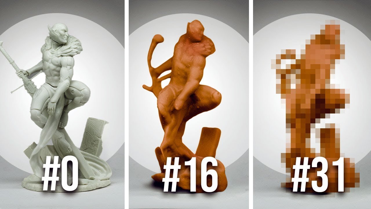
AD: To find out more about Collective studio click here: http://www.patreon.com/collectivestudio
What happens when you 3D scan and then 3D print the same figure 100 times? Well, we tried our darndest to find out! Thanks to the open scan 3d scanner and the phrozen 8k mini 3d printer we got quite far until the miniature couldn't stand on its own ...
this is the video i watched
surprisingly good results on a small scale
balmy pulsar
yeah.
when you have a fixed sensor and structured light source, you can do some amazing things
ocean orbit
ah, structured light IS what the kinect uses
balmy pulsar
basic photogrametry "fails" because it has to deal with arbitrary positions and lenses, and often shallow depth of field
ocean orbit
i thought it might be, though obviously a simple version
ocean orbit
anyway, 3d scannign is hard and expensive 😛
balmy pulsar
then you have scanners like creaform that use markers
ocean orbit
i saw a reddit post that basically put it pretty well i think, if its just a one off or something its probably cheaper just to pay a guy to copy whatever it is manually
balmy pulsar
and the last type is the good old arm. faro or romer or nikon. laser on the end, but the arm is calibrated to some microns, so it always knows where the laser is. these are usually the most precise options for engineering
ocean orbit
ive seena few requests to 3d scan a part i could build in a couple of hours and im a massive amature
balmy pulsar
on set, our main purposes of scanning is to get accurate dimensions.
for tracking and modellsing extensions
shy kelp
So in a nutshell there's nothing decent and cheap yet?
balmy pulsar
but i also scan props accurately so they can esplose etc
ocean orbit
this makes sense, it also makes sense if you are replicating a tonnnn of stuff
balmy pulsar
shy kelp
So in a nutshell there's nothing decent and cheap yet?
not your kind of cheap
ocean orbit
i mean, it depends on your definition of cheap and your definition of decent and the size of the thing you want to scan
but 200 is gonna be ROUGH in any definition
balmy pulsar
yeah
shy kelp
balmy pulsar
not your kind of cheap
Lowest amount? Just to have an idea, and see if it may be worth for me
balmy pulsar
the creality is $500. thats your entry into something "useful"
but i would stop short of calling it good
ocean orbit
how big of an object are you planning to scan?
balmy pulsar
my neighbour made a scanner. it was really hated by customers. i forget their name
ocean orbit
you can do up to 18cm squared wirth the open scan?
ocean orbit
i just think right now 3d scanners at the hobby level are going to be a pain either way
balmy pulsar
yes
ocean orbit
probably less of a headache to just pay someonme on fiver to do it for you
balmy pulsar
hehe
well, as an example, we charge lets say as a random number $2000 to show up and scan a set. We then charge $5000 or more to turn that scan into something useful. The "scanning" is the easy/cheap part. People in the hobby world want 1 button instant gratification, and scanning is not there (yet)
ocean orbit
whereas you cna probably pay someone on fiver like, $30 to copy a simple part 😛
So yeah, id maybe look into the open scan https://en.openscan.eu/
if you are only doing small parts but even then you will likely need to do cleanup

OpenScan
Günstige 3D-Scanner-Bausätze und ausführliche Anleitungen zum Thema Photogrammetrie und 3D Scan allgemein von OpenScan.
balmy pulsar
ha. i wouyldnt go that far. but yeah
ocean orbit
and its gonna be like 3 or 400
unironically i have considered looking into doing some modelling jobs when im more experienced but it would absolutely violate the fusion360 license so oof
balmy pulsar
100k is the fusion lic
ocean orbit
i thought they had swapped it to any proft, ill check
balmy pulsar
if you get to 100k, you can pay the 450
oh. i think officially you need to move to the registerd start up version
i forget now
they have changed it a few times
balmy pulsar
i sell fusion models of guitar. i made $1250 this year. ha.
which is not bad for not really doing any work
balmy pulsar
selling models is a completely viable "job" if you pick the right niche
ocean orbit
can i peek what you are selling?
i was more thinking of going on a commision thing personally but i am interested

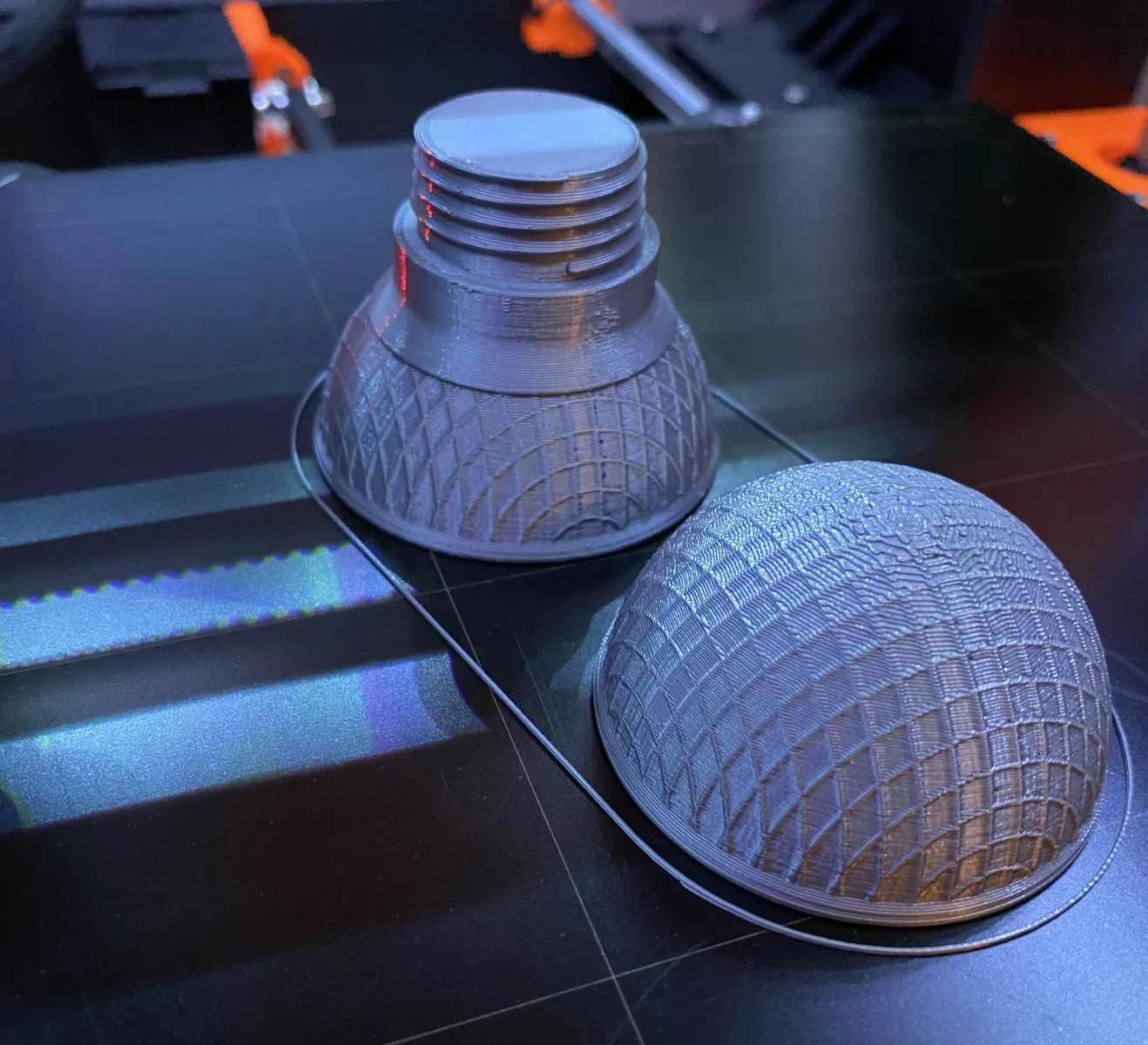 balmy pulsar
this will be the next big one to launch.


kid/travel size
but it is quite complex, so i need to make it "ingestible" to people.
ocean orbit
yeah, plus making it useable, makign something that L:OOKS like a guitar is i imagine the easy part of the situation
balmy pulsar
i want my cad sales to get up to over $1000 a month this year. we'll see
ocean orbit
I will cross my fingers for you, my goal this year is to expand my skill
been doing a bunch of modelling for various little projects and i suddenly realised "wow i should have done this at university"
ocean orbit
i am not artistic in the slightest so i would be screwed doing miniatures
balmy pulsar
people sell minature cad models for $5-$20 each. model one a week. after a year you have something pretty self sustaining
ahh
yeah im not great at organic
ocean orbit
sameee
balmy pulsar
better at spadce ships
😛
i am prepping to print this
needs some work
i cant sell that of course (technically i guess i did "sell" it to microsoft hah)
ocean orbit
hah even then im kind of rubbish, creatively i struggle, if you want a practical part or bracket or mechanism or something along those lines i can probably do it, but making something creative and aesthetic
not so much
balmy pulsar
also need to make a printable 6 foot tall rocinante one day
but they never alocate time for it
ocean orbit
thatw ould certainly take a while
I have the basic idea for a clock kit in my head at the moment, mostly 3d printable with an electronics BoM
balmy pulsar
well the rocinante model is a complete dumpster fire. it is meant to render, not print of course. it will take an intern like 3 weeks to make it "manifold"
balmy pulsar
ok, so fusion "start up" is $150 for 3 years now. so not free, but still pretty acceptable
ocean orbit
Thats definitely doable if you are making over 1k a year
shy kelp
There's also rhino
1k Perpetual licensing
Or about 200 as a "student"
balmy pulsar
rhino is not a similar software
rhino is freeform surfacing (its more than that, but that is the core)
where fusion is parametric solid modelling
there is some overlap, but they have fundametally different purposes
shy kelp
Mah I don't see them being so much different
As much rhino is not parametric by default it can be with grasshopper, which now is well integrated
Bruh this year I'm 24
balmy pulsar
ive been doing 3d since before you were born. 😛
ha
waitn, no, i mean im 29
yeah thats it
ocean orbit
if i was to swap from fusion i would likely move to something free rather than another paid product
shy kelp
What's there freecad? Pretty bad imo
ocean orbit
though the free options are from what i have heard, variable in their utility
balmy pulsar
i need the machining side of things, and there isnt much free that is worth using