#circuitpython-dev
1 messages · Page 221 of 1
 obsidian dome
 tulip sleet
Currently removing stuff is somewhat ad hoc. You'll want to look at ports/atmel-samd/mpconfigport.h and maybe boards/trinket_m0/mpconfigboard.h
 raven canopy
@cunning trail in reading the article, and looking at Debra's blog, seems that for the handbags/headbands she's using the Gemma (naturally..best fit). To get around the file size with hardware, ItsyBitsy M4 would be the closest wrt size constraints. Then there is also Roy's pixelbuf work that may help on the M0 too. Having said all that, MakeCode seems the "better" suggestion in the interim?
tulip sleet
@obsidian dome you may want to use the 3.x branch right now instead of master, which is undergoing churn as we develop 4.0
obsidian dome
danh: Thanks. I'm looking into it. Right now I'm setting up a VM for building.
tulip sleet
Feel free to return here for help. A number of folks who hang out here have done their own builds
obsidian dome
Looks like I can easily loose touchio, i2c and SPI for my project
raven canopy
@obsidian dome what OS are you on?
raven canopy
k. i was going to suggest WSL if you're on Windows. Its the "fastest" compile time-wise.
interesting. anyone else stumble upon this recently?
https://github.com/actions
https://github.com/features/actions

GitHub
Automate your GitHub workflows. GitHub Actions has 16 repositories available. Follow their code on GitHub.

GitHub
Easily build, package, release, update, and deploy your project in any language—on GitHub or any external system—without having to run code yourself.
obsidian dome
Any suggestions for how to determine which modules use the most space?
 ruby atlas
I saw they announced it, but wasn't aware it was available yet.
raven canopy
still beta, but it showed up on the CP repo. (which is how i came across it)
ruby atlas
@obsidian dome hmm.... i wonder if the object sizes are useful there.
obsidian dome
That's what I was thinking, but sometimes small objects have massive dependencies in code. Don't know if circuitpython will be like that.
ruby atlas
find build-metro_m4_express -name \*.o -ls
That's why I wondered about it.
build-metro_m4_express/firmware.elf.map might help
(use your build dir instead)
I can't remember if the map is produced if you don't use DEBUG=1
obsidian dome
Kudos to whoever manages the circuitpython repo. Once I got to the learn page it all worked like a charm. The only trivial issue was checking out 3.x as three directories from master (lib/tinyusb, ports/nrf/nrfx, tools/huffman) weren't empty. But hey, I know now to rename a directory. Again, kudos for a good tutorial and process.
ruby atlas
 yeah, I still refer to the debugger setup instructions page instead of remembering it. I ❤ Adafruit Learn.
 lethal abyss
I use a Trinket M0 Express with CircuitPython 3.1.1 and libs bundle from 12/29/2018
Trying to use a LED 7-segment Display
As in the doc, when reaching
display = adafruit_ht16k33.segments.Seg7x4(i2c)
Generates an error: NameError: name 'i2c' is not defined
Here some photo of the wiring
Trinket M0
https://photos.app.goo.gl/bsmJMYGT3PXyopBE9
Led Backpack
https://photos.app.goo.gl/8TfvWC1onWZRoYq26

Google Photos

Google Photos
 tidal kiln
sounds like you didn't create the i2c bus
do you have a line of code that looks like this?
i2c = busio.I2C(board.SCL, board.SDA)
oh... right :)
The problem was I jumped to the Led Backpack in the doc and forgot this line. Thanks
tidal kiln
np. what doc are you reading?
lethal abyss

How to use LED Backpacks & FeatherWings with CircuitPython!
everything is there but I made this quick read jump.
tidal kiln
hmmm. yah, that's written so the individual sections aren't really code complete.
lethal abyss
that's easy to jump that line (I saw the import lines just before)
tidal kiln
yep. the "I2C Initialization" section applies to all the displays - the sections that follow
take a look at the examples in the library also:
https://github.com/adafruit/Adafruit_CircuitPython_HT16K33/blob/master/examples/segments.py
having complete code to look at helps
lethal abyss
oh nice, I was looking for example like this but was looking for something with the name of the library I use (adafruit_ht16k33)
perfect, I'm doing a little countdown gadget for the fun
 marble hornet
If the esp 32 has two cores can Cp run on just one? (Just conjecture. Not request or suggestions)
Leaving the other available for wifi sterf ?
 stuck elbow
I didn't know thete was CP for esp32
 solar whale
There is not and there is not likely to be...
solar whale
@marble hornet some interesting stuff on using both cores with Arduino https://www.hackster.io/rayburne/esp32-in-love-with-both-cores-8dd948 --- I did some quick google searches for micropython on dual cores and there appears to be work on this. I did not dig too deeply.

Hackster.io
Arduino on the ESP32 is a match made in heaven: One core for RF and one core for Arduino; but you can cheat and get more Arduino resources. By Ray Burnette.
 manic glacierBOT

 meager fog
@umbral dagger hey hey
the guides are ready to live in a min...but i was wondering, i think the debouncer should go in a helper library no? seems like ya use it alot?
 umbral dagger
@meager fog Yeah, we'd mentioned that. Kattni and I are going to sit down and talk (me) through it to make it happen. Just haven't gotten mutual time to do that yet. There's a couple tweaks I want to make to it to make it more generally useful. It's on my list for the new year. That said, it's getting a fair bit of testing.
meager fog
kk its not too hard - i have a checklist
if ya can, for the garmin guide, can you take a 2-3 sec gif of you spinning it in your hand so we can see the lens part?
like turning it around so you can see that there's a lidar sensor on the other side 😃
 hazy gust
ive been intersted in that myself, that page is giving 404

Share your code with the world
hazy gust
ah 😃
 wooden lichen
What is the maximum pwm frequency for the M4 in circuitpython?
For example in the code "led = pulseio.PWMOut(board.D13, frequency=5000, duty_cycle=0)"
 exotic pumice
I can't quite recall but I think it's like 20-50KHz-ish or less
it's definitely in the KHz range
 hearty edge
First time here... Looking for some help with libraries. Not sure how to change default settings. For example - changing the range on the L3GD20 gyro.
meager fog
nav, check the docs here https://circuitpython.readthedocs.io/projects/l3gd20/en/latest/api.html
marble hornet
@solar whale thanks for the link!
Separately:. Is there a good reason to go 32 over 8266 when doing cp wifi?
meager fog
yes esp32 can to secure connectiosn better/faster
hearty edge
Thanks, but my mechanical engineering background is showing. Tried
sensor = adafruit_lsm303.LSM303(i2c,rng=0)
and got back TypeError: unexpected keyword argument 'rng'
umbral dagger
@meager fog Converting a spin gif now. Where do you want it?
hearty edge
Apologies...being a dingbat. I am working with both. Trying to use my Metro Express with ZumoBot.
umbral dagger
@meager fog have a look
tulip sleet
@hearty edge adafruit_lsm303.LSM303() only takes an i2c argument, not a rng argument. Just take that away for now.
hearty edge
@tulip sleet Thanks - got that. Now trying to write set a register on L3GD20. Trying SENSOR.write_register(_L3GD20_REGISTER_CTRL_REG1, 0x0F) and getting a NameError.
Fubling my way through "class" and "parameters"...
tulip sleet
@hearty edge the _L3GD20_REGISTER_CTRL_REG1 value is not available (normally you'd use SENSOR._L3GD20_REGISTER_CTRL_REG1) because it's a compile time const due to special rules (it's set via const(...)). Do you need to set the register yourself? We already set it to 0x0f in __init__()
hearty edge
@tulip sleet Thanks again. What I am really trying to do is to get a handle on how to use the libraries to control the different aspects of the sensors. I would like to have my students - mechanical engineering sophomores - to use these devices so I am trying to do a deep dive. I am trying to decide how much background info I need to use a given sensor and its associated libraries. I don't want to treat them as "black boxes"
tulip sleet
@hearty edge I have to go out for a while. I'd suggest starting with the current driver and then modifying it, as opposed to using it as it is, because it's set up for a particular style of use (hence you can't write the registers yourself).
tidal kiln
@hearty edge the library is too much of a black box in this case? you're going to want them to understand the registers?
hearty edge
@ @tidal kiln @tulip sleet I guess that the ideal thing would be to have some more examples that could be used to explore the capabilities of a sensor. The libraries reference the information provided on the data sheets, but it's not obvious to a novice how to explore/implement the functionality.
tidal kiln
sounds like maybe the examples are too simple?
or is there functionality of the sensor that is not currently implemented in the library?
hearty edge
@tidal kiln Examples are too simple (IMO)... The libraries look to be very complete.
tidal kiln
ah. ok.
it's a trade off
for each library we want to have, at a minimum, a "simple" example that truly is very simple
not much more than a "hello world" for the sensor
some libraries will have additional examples that explore things further
or maybe covered by guides in the learn system
marble hornet
the 840 has zigbee!?
hearty edge
@tidal kiln BTW - I am a BIG fan of everything Adafruit has done and continues to do. I just usually approach learning things with the idea that I will eventually have to explain it to someone else. What I need to do is to get more proficient with Python. Do you have any recommendations that would be particularly geared towards Circuitpython?
marble hornet
did the 8266 support wifi in 3.1.1? or just running on it
tidal kiln
anything Python would be fine, it should translate fine to CircuitPython
CP tries to do everything in a way that's backwards compatible with CPython - which is what you're probably running on a PC
this tries to explain some of the main differences:
https://learn.adafruit.com/circuitpython-essentials/circuitpython-expectations#differences-between-circuitpython-and-python-18-7
meager fog
@hearty edge we do have a guide that shows going thru a datasheet to make a sensor driver. python's a lil different than C but i find it easier to code sensor drivers in python

Learn about porting an Arduino library to CircuitPython with the VL6180X distance sensor.
that may be helpful so youc an see the 'thought process'
tulip sleet
@marble hornet it does support wifi, using mostly the MicroPython supplied modules
@hearty edge for books, if you're already a programmer, I can suggest:
https://www.amazon.com/Python-Nutshell-Desktop-Quick-Reference/dp/144939292X/ (front section has a concise introduction)
https://www.amazon.com/dp/0321680561/ (somewhat out of date (early Python 3.x) , but well written)
https://www.amazon.com/dp/1617294039 recommended by others but I have not looked at
hearty edge
@meager fog Thanks! I'll take a look. BTW - Congrats on the Forbes Top 50.
meager fog
nav, thanks - and if you end up writing drivers let us know we'll include in the bundle! 😃
hearty edge
I'm an ME so not likely, but maybe a tutorial or two as I figure things out....
meager fog
you'd be surprised ! there's a lot of mechatronics out there people like to use python with - you could have a lot to contribute 😃
@umbral dagger here for a few mins, lookin' @ LIDAR
meager fog
Adafruit Industries, Unique & fun DIY electronics and kits : - Tools Gift Certificates Arduino Cables Sensors LEDs Books Breakout Boards Power EL Wire/Tape/Panel Components & Parts LCDs & Displays Wearables Prototyping Raspberry Pi Wireless Young Engineers 3D printing NeoPix...
ruby atlas
Man, the maker world is getting so awesome!
I wish all this fun stuff existed when I was an 8yo dabbling with electronics.
meager fog
me too! thats why i made some of it 😃
ruby atlas
yay!
Thanks! I hope yet to get my kids excited by it, but it's harder now that there's so much electronic magic around them.
meager fog
@umbral dagger 🤦 i forgot to ask if the spinning lidar could have the LEDs be on, if it isn't too much bother do you mind regiffin' but with it turned on
marble hornet
@tulip sleet mircopy code on cp for wifi ?
 sinful sand
I'm building a model theatre for my daughter (Previously posted in #help-with-projects ). I want to have sound, lights and servo or motor control. I have a TrellisM4 which gives me the sound capability and the buttons to control everything. It has been suggested I buy an Itsy Bitsy to run the neopixel LEDs that will be the stage lights and the servos/motors to raise/lower the curtains. Can I connect the Itsy Bitsy and the TrellisM4 over I2C? How would I go about passing a key-press event on the TrellisM4 to the Itsy Bitsy to say, change the colour of the neopixels? Or actuate the servo?
ruby atlas
One option would be to use serial
sinful sand
@ruby atlas Ok. I am a novice with CP. I have read through a learn guide on I2C - SPI but it was about connecting a sensor not microcontroller to microcontroller. Are you aware of any sample code that may give me a starting point?
ruby atlas

The next step in learning CircuitPython.
The JST port can be used as I2C, ADC, or UART.
https://www.adafruit.com/product/3938 Finally, a 4 pin JST hacking port is available for extra add-ons. It's STEMMA and Grove compatible, and provides GND, 3.3V power, and two pins that can be used for I2C, ADC, or a UART. So connect some other sensor, or read stereo audio in, or maybe hack together a MIDI port. Whatever you like!

We got a big ol' blender and tossed in an ItsyBitsy M4, two NeoTrellis boards and an electret mic amp - turned on the 'mix' button and out came the NeoTrellis M4 - a super fun ...
https://www.adafruit.com/product/3800 can be powered from the 3.3v of the STEMMA port making it a single wire bundle (4 wires) to connect the two boards.
What's smaller than a Feather but larger than a Trinket? It's an Adafruit ItsyBitsy M4 Express featuring the Microchip ATSAMD51! Small, powerful, with a ultra fast ATSAMD51 Cortex ...
 steep moth
The ItsyBitsy M4 Express can also play audio files.
ruby atlas
There are sooo many awesome boards 😃
steep moth
I ❤ my ItsyBitsy M4 Express. I can't wait to get the Adafruit Grand Central.
ruby atlas
You could also probably just use the Trellis M4 to control everything.
umbral dagger
@meager fog Will do. After dinner.
marble hornet
@steep moth I have the same sentiment about the itsy m4
Aren't they great!
But that gc m4 🤤 more wam
sinful sand
That looks useful and I will read with care. I would be grateful for any code samples that specifically detail passing a key-press event on the TrellisM4 to an Itsy Bitsy. @ruby atlas Can I connect neopixels to the TrellisM4?
ruby atlas
Signed up for the Adafruit Grand Central!
steep moth
They are awesome, I started to use mine with Circuit Python, but I found it easier to accomplish my goals in Arduino, so I started using my M4 in Arduino.
ruby atlas
@sinful sand yes. Let me find the pinout details. Neopixels just need data and power.
steep moth
I hope the Grand Central is not too expensive. I think it will probably be around $40, which is kind of out of my price range.
marble hornet
What is this Arduino you speak of, I've Never heard of it?😉
My guess is 35 🤞 but once it is out one could easily make their own (via copy)
Like as part of a project
sinful sand
I bought my TrellisM4 because of the M4 chip, the large memory, the sound capabilities and of course the LEDs/buttons!
ruby atlas
hrm, i can't find the pinout details for the board beyond a few mentioned on the learn guide.
marble hornet
Is the trellis m4 256 k ram or 192?
ruby atlas
i don't feel like figuring out how to read the board/schematic file 😃
steep moth
"512 KB flash, 192 KB RAM"
sinful sand
I have had a lot of fun with mine - who doesn't love light-up buttons.
steep moth
It now has a new silkscreen on the back.
ruby atlas
Trellis M4 = SAMD51G19A, GD25Q64C flash. Metro M4 = SAMD51J19A, S25FL116K, S25FL216K, GD25Q16C flash.
(per boards/*/mpconfigboard.mk)
Same chip so same ram makes sense.
sinful sand
I saw that. I think I'm glad I have one of the 1st ones.
ruby atlas
I have one from the adabox010 and 2 more for the kids I got shortly after that also ahve the fancy silkscreen.
I've got one currently doing an FFT spectrum analysis of the music pumping out of my mixer to my office 😃
sinful sand
They do look nice.
ruby atlas
They were out of stock on the acrylic cases, so I designed an OpenSCAD 3d printable case.

This is a snap-fit case for the Adafruit Trellis M4 board and buttons.
The OpenSCAD files can be easily modified to support multiple boards or to add support for adding NeoTrellis boards. Keep an eye on this project for updates that support 8x8 or 4x8 cases.
This is design...
sinful sand
I can't see a way of controlling neopixels and a servo with just the JST/STEMMA port. Other than via another MC.
ruby atlas
You'd have to send control sequences to something like the trinket.
sinful sand
More thought required and hopefully some example code to connect two MCs. Off to bed now, it is late in GMT land.
 idle owl
There was another community member communicating between two Itsy Bitsys but I don't remember who.
They were using UART afaik.
 upbeat plover
i want to do UART to feather M4 to feather adalogger
ruby atlas
Hmm i really wanna know what the grid of pads is on the back of the trellis m4.
OpenBoardView installing 😃
that didn't work
next
exotic pumice
eagle has a free version
ruby atlas
ty
exotic pumice
@tulip sleet, are you skilled enough with git to know how I could get that patchset for samd51 into a more recent openocd?
umbral dagger
@meager fog New gif in place. I replaced the guide thumbnail as well.
exotic pumice
git cherry-pick?
marble hornet
Is there a wifi coprocessor guide yet?
ruby atlas
No.
@marble hornet Dumping notes from jerryn to you:
https://discordapp.com/channels/327254708534116352/327298996332658690/527997507054338058
/usr/local/bin/esptool.py --chip esp32 --port /dev/ttyUSB0 --baud 115200 --before default_reset --after hard_reset write_flash -z --flash_mode dio --flash_freq 40m --flash_size detect factory_WROOM-32.bin
https://github.com/adafruit/Adafruit_CircuitPython_ESP_ATcontrol
@ruby atlas -- you can use teh library from here (I htink it is in the latest bundle as well) and the demos in the examples should work -- see the demos code for the pins to wire up -- GPIO15 is critical for flow control - you need to connect RX,TX,VUSB,GND,GPIO15,RESET from the ESP32 to the metro M4 -- swap RX/TX - use the recommended or any other GPIO for the GPIO15,RESET(edited)

GitHub
Contribute to adafruit/Adafruit_CircuitPython_ESP_ATcontrol development by creating an account on GitHub.
HTH
idle owl
@ruby atlas @marble hornet https://learn.adafruit.com/adding-a-wifi-co-processor-to-circuitpython-esp8266-esp32

Surf the 'net with Blinka!
ruby atlas
oh!
that would have helped me 😃
There's so much stuff on the adafruit learn system now I find it hard to navigate.
marble hornet
@ruby atlas I totally! Agree.
exotic pumice
I think my adapter speed might've been too high. I have working breakpoints!
I also updated openocd
ruby atlas
I'm using the segger jlink and arm-none-eabi-gdb-py build-metro_m4_express/firmware.elf -ex "target extended-remote :2331" 😃
exotic pumice
yeah I'm doing some super janky openocd raspberry pi stuff
marble hornet
And thanks @idle owl
exotic pumice
I think I'm on my way to success
here I have a comparison of oscctrl bits on my rust program and on arduino
ruby atlas
heh 😃
exotic pumice
now I just have to look up all the ones that are different
umbral dagger
@meager fog I'm seeing the Garmin guide, on 'learn.' but without a live link.
meager fog
@umbral dagger heya back - https://learn.adafruit.com/garmin-lidar-lite-range-finder ?

Measure distances using lasers. LASERS! No sharks, though.
umbral dagger
@meager fog It's good now.
meager fog
thanks, sorry had to hit a button
ok i checked off the 3 that went live!
whatcha wanna do next?
steep moth
Nice simple learn guide. Nice!
meager fog
@umbral dagger how bout a 2d lidar with a pi, you wanna try writing a library for it?
umbral dagger
@meager fog I was wondering about using a Feather M4 (possibly the Grand Central?) for that.
meager fog
feather m4 would do a fine job
TG, there's an existing guide. thats what we have now. no ETA for more, its very alpha and experiemental!
exotic pumice
my metro m4 randomly can't write to 0x00006000 anymore
marble hornet
@meager fog okay, subject to change then? Should I be worried about working changes or am I fine PCB wise ?
@exotic pumice external or internal?
exotic pumice
@marble hornet huh?
oh, internal
afaik
maybe I'll try a uf2 on it to see if that unlocks it somehow
marble hornet
On the chip or as part of the USB drive ?
Can you paste the error ?
Ah. Can you run earse file system with a trinket firmware?
Or wire an Arduino sketch ?
exotic pumice
Error: SAM: NVM programming error
Error: Failed to erase block containing 00006000
Error: SAM: failed to erase sector 3 at 0x00006000
Error: failed erasing sectors 2 to 4
Error: flash_erase returned -4
(gdb) load blinky_basic.elf
Error erasing flash with vFlashErase packet
@exotic pumice I wasn't sure about the openocd patch set, if it even came from git. You would use the patch command, not necessarily git. I wish it was just in a repo somewhere.
exotic pumice
yeah it is a git repo it's just not on github
marble hornet
What programming tool are you using? Jlink?
manic glacierBOT

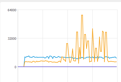
ok so i did more testing tonite, and used the mu plotter to get a sense of the data and it seems really spikey, did you notice this too?
exotic pumice
it's a bit jank
it was working pretty well for the past few hours though
now all of a sudden, can't write
exotic pumice
I've power-cycled and run a bunch of stuff that's supposed to erase and clear protection flags
to name a few
atsame5 chip-erase
flash write-image erase unlock
flash erase_address unlock
i have no real experience with openocd, unfortunately
marble hornet
Neither myself
exotic pumice
yeah
marble hornet
Have you tried running the bin without over uf2. Like loading cp.bin into memory?
tulip sleet
or, you can convert all the .bin's to uf2, and load that way
uf2conv.py is in the circuitpython repo and also the uf2-samdx1 repo
with the j-link mini edu, you can run the gdbserver also and use the load command
tulip sleet
it means the bootloader is running, waiting for an upload (UF2 or arduino style)
exotic pumice
oh I fixed it
I loaded through a separate openocd command, and then loaded through gdb as well
weird
exotic pumice
my clocks bleeping work!!!!!!!!
samd51 hal ready to go possibly
this is huge for me
tulip sleet
great! gotta say good night! but congrats!
exotic pumice
g'night @tulip sleet
marble hornet
Night @tulip sleet
Sleep well
Separately
Can you scan for IP addressssss over at?
Ah, okay
I see
 tawny creek
I think you can get a list? @marble hornet
marble hornet
Do you see example code?
tawny creek
GitHub
Contribute to adafruit/Adafruit_CircuitPython_ESP_ATcontrol development by creating an account on GitHub.
exotic pumice
that's access points
exotic pumice
you'd probably have to ping a range and see who responds
marble hornet
Hmmm okay.
tawny creek
ahhh IP's sorry yeah thought you meant list of access points
exotic pumice
on a PC I'd use nmap, on an ESP idk really
marble hornet
Is this English ?
exotic pumice
lol
Nmap Free Security Scanner, Port Scanner, & Network Exploration Tool. Download open source software for Linux, Windows, UNIX, FreeBSD, etc.
what is your use case?
marble hornet
Making a wifi connected device where consumers would set it up
A wifi flow guage
So it needs to be connected to a phone or something somehow
Wifi does need to happen
For it though
Am I being clear? Am I englishing ?
exotic pumice
why do you need to scan for IP addresses?
upbeat plover
@exotic pumice did you need to change the BOOTPROT like i need to to get it to write?
exotic pumice
no, I just wrote with a different command and it seemed to clear things up
it wasn't even in the bootloader range I don't think
exotic pumice
have you guys seen this micropython talk at 35c3? https://www.youtube.com/watch?v=xCPnOxWxHIc

https://media.ccc.de/v/35c3-9648-micropython_python_for_microcontrollers How high-level scripting languages make your hardware project beautifuly easy MicroP...
just checking it out now and thought you guys might be interested
 mint remnant
I don't use python because i use c and c++ now for 30 years but i will download the video and listen. Thank You @exotic pumice
 lone sandalBOT

 timber mango
Hi
raven canopy
hey @timber mango! 👋
 halcyon wolf
@exotic pumice I watched the video...very interesting....I must explore further. Like Mike, I'am far more used to C/c+ and java than python. I watched another presentation by the creater of micropython and it's apparently being used in some serious stuff. Interestingly he did question the need for circuitpython as an "easier" version of python.
timber mango
I try to write a driver to use the M4 board as two neotrellis
to be able to put everythong in one multitrellis instance
so I try to understand how neotrellis (with Seesaw) works to do the same with the trellis M4
raven canopy
i haven't used or delved too far into either of them, yet. i imagine you could interface them over I2C with the Seesaw (SAMD09). are you on working on the C side or the Python side?
timber mango
only on the python side
but I need to understand what data the seesaw is sending over I2Cto code the same behavior on the trellis M4
solar whale
@pastel panther Thanks for reviewing/approving the rfm9x. If you have time would you also take a look at thr rfm69 -- same fix https://github.com/adafruit/Adafruit_CircuitPython_RFM69/pull/14 -- cut/paste is dangerous thing 😉

GitHub
Corrects an error if packet header receipt is enabled but packet is not addressed to recipient and filtering is enabled.
marble hornet
hey, i'm looking to use this: https://www.adafruit.com/product/1400 to switch power in project (the tricorder) but the button can't be physically pressed. i see that the output of the nand gate is connected back to the input by a not gate. can it be hacked into it somehow? else could i please have some mosfet help 😅 (i'm not great at them) . other suggestions welcome too. thank you either way

The Adafruit Push-button Power Switch is a tidy little design that lets you control a DC power source using an everyday tactile button. The breakout uses a latching analog circuit that is ...
please 😅 😀
i have a capacitive touch sensor as an input rn
raven canopy
@timber mango in looking at the NeoTrellis library, seems that it's just using the Seesaw library. So, that should give you some insights.
NeoTrellis importing Seesaw: https://github.com/adafruit/Adafruit_CircuitPython_NeoTrellis/blob/master/adafruit_neotrellis/neotrellis.py#L51
Seesaw library files: https://github.com/adafruit/Adafruit_CircuitPython_seesaw/tree/master/adafruit_seesaw
solar whale
@marble hornet so you want to replace the pushbutton with your cap. touch switch?
solar whale
so - can't you just do that in the circuit? or is the cp touch also powere y the same source. Is that the problem?
marble hornet
the cap touch is separate (it's the same regulator output but turning off the rail to the m4 and sensors )
i'm just really bad at using mosfets and transistors (smd) i can rarely get them to work. the m4 and such will draw more current than the cap chip can provide
solar whale
right -- I am by no means an expert on ths, but it looks likea good place for a transistor -- the Cap touch would just turn the transistor on/off to close/open the point where the pushbutton is. Does that make sense?
solar whale
I would think momentary -- just like the pushbutton
while the button/captouch is pressed, the circuit is closed.
upbeat plover
is it possible to remap TX and RX? was thinking of putting a feather and hallowing together but the RX and TX will be in same place.
i already tested so if anything crazy happens when i connect the two running different stuff, hallowing was running slide show, and adalogger was logging sensor data
marble hornet
in addition to the pushbutton! okay now i;m on the same page.
solar whale
or instead of it -- I was just saying that the pusbutton action is more like momentary than toggle.
it makes contact while it si pushed
marble hornet
i have a bunc of these laying around. (i agree, i though the transistor was replacing the pushbutton board, now i see what your'e thinking, 👍 )
solar whale
ok -- I thought just just wanted to hack into that board.... may be a much simpler way to do it.
marble hornet

Transistors are powerful little electronic switches, and we really like these NPN and PNP transistors whenever we need to control medium-power electronics, such as small motors, solenoids, ...
yeah. i'm reordering the board with touch so i don;t mind changing to toggle
solar whale
there may be a much simpler way just using the cap touch and a transitor or mosfet alone.
solar whale
I was focuse d on how to tap into the circuit you posted -- not on the implmentation
you might want to jump over to #project -- there are some folks there who may be of great ehlp.
ruby atlas
wheee:
WARNING: CPU could not be halted
Failed to halt target device on connect```i was light on implementation description. however the hacking would be quite fun. (too space inefficient though if just a transistor would work)
thank you @solar whale i'll take a jump over
upbeat plover
{ MP_ROM_QSTR(MP_QSTR_TX), MP_ROM_PTR(&pin_PA10) },
{ MP_ROM_QSTR(MP_QSTR_RX), MP_ROM_PTR(&pin_PA11) },
solar whale
thats what I meant
upbeat plover
i change those two right?
exotic pumice
I think you just figure out which pins are available to be tx or rx on the sercoms and then tell busio to make a uart out of them
upbeat plover
TX and RX are not something specail just name of pins? i can just change code around and it works?
exotic pumice
The code you pointed at is just binding the names
They can only be sercom pins
There's a script somewheres that tells you which
upbeat plover
one board id do this ?
busio.UART(TX, RX, baudrate=115200, timeout=3)
and other board this?
busio.UART(RX, TX, baudrate=115200, timeout=3)?
solar whale
@upbeat plover since the pins are physically tied together, I don;t think you can use them to communicate between the boards.
since thay have to cross over between the boards to work.
upbeat plover
okay ill have to do something else then, like use a statemachine and just check up or down between pins
exotic pumice
The link I posted is a script that tells you which pins can be UART
upbeat plover
@exotic pumice i ran script has long printout
solar whale
perhaps I'm wrong -- if you rediine the pins on one side to swap RX/TX, then I think it should be OK - pin is just a wire.
upbeat plover
D0 is not a TX pin so i dont think i can just switch code around
solar whale
yo would have to rebuild CP with swapped pins on one board
exotic pumice
If the script tells you you can, you can. That's the magic of sercoms
exotic pumice
It's from the guide here https://learn.adafruit.com/circuitpython-essentials/circuitpython-uart-serial
The next step in learning CircuitPython.
upbeat plover
hmm ill have to run it on hallowing but looks like i can use different pins and do what i wanted
exotic pumice
Yep, whatever pin combos the script tells you, just do busio.UART() and you have a new UART
Getting rid of the old one is a separate problem
I guess that's actually what you want. Sorry.
upbeat plover
How do you get rid of old ones?
exotic pumice
I guess it probably uses the one bound to the name like you were showing before as the main one
MP_ROM_QSTR....
upbeat plover
okay so in pins change those to the new ones i see?
exotic pumice
Try it and see
upbeat plover
alrighty
exotic pumice
I've never done it before
upbeat plover
might take a bit, but ill update once boards are running changed CP
solar whale
@upbeat plover which board are you runnig the modified CP code on?
upbeat plover
both
hallowing and feather M0 adalogger, changed both D6 to TX and D10 to RX
building now
solar whale
OK but I' confused don't you want to cross TX/RX between the boards
upbeat plover
oops orignal problem forgot to switch lol
solar whale
and you can't use D0/D1 on those boards? just swap on one of them?
upbeat plover
hallowing d6 = TX d10= RX, adalogger D6= RX d10 =Tx
have yet to test anything came here with my thoughts first
D0 would not have worked not a sercom
solar whale
on which board?
upbeat plover
both its not TX
solar whale
ok -- I was looking at a diferent board (ItsyBitsyM4) it is on that one.
upbeat plover
anyone have a simple script to test this with?
marble hornet
@idle owl i was listening to the weekly again and wow that was an impressive amount of work you did !
idle owl
😊 Thanks!
solar whale
@upbeat plover ah -- now I see -- not on hallowwing -- too bad.
upbeat plover
moddified CP on both boards now
solar whale
oos -- ignore taht old version -- just a sec
@upbeat plover here is the alpha5 compatible version ```import board
import busio
import time
RX = board.RX
TX = board.TX
with busio.UART(TX, RX, baudrate=115200, timeout=3) as uart:
while True:
data=input()
if "reset" in data:
uart.write(bytes("\x03","utf-8"))
uart.write(bytes("\x04","utf-8"))
else:
uart.write(bytes(data+"\r"+"\n","utf-8"))
getresponse = True
while getresponse:
response=uart.readline()
print(response)
if(response == b'' or response == None ):
getresponse=False
Invalid Pins😬
solar whale
??
upbeat plover
yeah no clue why, im gana edit build and see if i remove the D6 and D10 and only have the PA to RX and TX
solar whale
where do you get the "invalid" pins message?
upbeat plover
line 8
solar whale
post the code you are running
upbeat plover
i copy pasted the alpha5 , where the time is 3 and not 3000
solar whale
but did you remap RX/TX in your build -- try using D6/D10
upbeat plover
building new CP right now with D6 and D10 removed and only having them as RX and TX
okay, ill try default CP next with D6 and D10 defined where they go
solar whale
that is what I meant -- use D6/D10 in the script - with your modified CP
timber mango
@raven canopy thankyou. I'm looking at the seesaw lib but I don't fully understand what the seesaw keypad does and send over I2C
I guess I have to experiment a little with neotrellis first
upbeat plover
@solar whale everything i try gives invalid pins for line 8
even current CP build with RX and TX pins lol
solar whale
so in the script you replaced RX with D6 and TX with D10 -- in both places
meager fog
@tidal kiln heya i can review the guide now
solar whale
what __ can you post the code and error mesasge that fails on current CP?
upbeat plover
import board
import busio
import time

RX = board.RX
TX = board.TX

with  busio.UART(RX, TX, baudrate=115200, timeout=3) as uart:
    while True:
        data=input()
        if "reset" in data:
            uart.write(bytes("\x03","utf-8"))
            uart.write(bytes("\x04","utf-8"))
        else:
            uart.write(bytes(data+"\r"+"\n","utf-8"))
        getresponse = True
        while getresponse:
            response=uart.readline()
            print(response)
            if(response == b'' or response == None ):
                getresponse=False
main.py output: Traceback (most recent call last): File "main.py", line 8, in <module> ValueError: Invalid pins
with CP alpha 5
solar whale
that fails on current master CP -- or your modified CP?
upbeat plover
current master
upbeat plover
oh
solar whale
whew! thanks @meager fog
upbeat plover
okay ill try moddified again
 warm spoke
Hi all
I new to IOT 😃, but have been lurking on adafruit.com for some months now looking components and guides over. It's been ~10 years since I did C# and VB.NET development, so I thought CircuitPython was a good place for me to start anew. As a first project I want to read (using the https://learn.adafruit.com/using-ds18b20-temperature-sensor-with-circuitpython/hardware guide) temperatures from some 1-wire DS18B20 sensors I have been using with my smart house installation (www.loxone.com) and post these to a API interface on the smart house controller. I have therefore purchased a Feather HUZZAH ESP8266 board and have successfully flashed it with CircuitPython 3.1.1. My next step was to connect board to my WiFi network, but I'm not actually sure how to do that using CircuitPython as the most relevant guide, I have found so far, (https://learn.adafruit.com/adding-a-wifi-co-processor-to-circuitpython-esp8266-esp32) assumes that the Wifi board is the HUZZAH ESP8266 Breakout board running ESP8266 AT firmware and being managed from a Feather M4 Express running CircuitPython.
Is is unrealistic for a newbie like me to do everything on my single Feather HUZZAH ESP8266 board running CircuitPython?

How to connect and use a DS18B20 one-wire temperature sensor with CircuitPython!
upbeat plover
is there some kind of check in busio im missing?
meager fog
doc, you could - but we are sorta moving away from useing the bare esp8266 with circuitpython... might be better to try micropython for your project
solar whale
@upbeat plover -- what happened?
meager fog
doc, this is the only circuitpython wifi on esp project we've published https://learn.adafruit.com/circuitpython-totp-otp-2fa-authy-authenticator-friend/software - but it did work

Keep accounts secure without frustration
upbeat plover
invalid pins still, i tried current CP and just do RX = board.D6 and it fails
stuck elbow
@hexchat the wifi stuff is the same as for micropython, so you can use those guides
upbeat plover
but when i run the UART_Test_Script it says D6 is both RX and TX
solar whale
I think that measn it can be either, but it is defined as one of them
upbeat plover
it fails and says Invalid Pins if RX is anything other then PA11
warm spoke
Thanks ladyyada. I'll have a look at the 2FA TOTP guide 😊
upbeat plover
or TX anything other then PA10
ill think ill just do as you suggested and cut and jump, make it cross pins physically
solar whale
taht is on current CP -- on which board -- hallowing?
upbeat plover
yea hallowing
solar whale
taht is how it is defined on adalogger
rX = PA11, TX = PA10
not on Hallowing
on Hallowwing RX = PA09 TX = PA10
@upbeat plover I have to go AFK for awhile -- I suggest double checking how things are defined -- good luck.
upbeat plover
on both boards it wont let me change RX or TX
 valid falcon
I think this is a very basic question but I've been struggling with it and would appreciate some help. I'm using the Hallowing and using capacitive touch to trigger an led blink. Using the built in led on pin 13 works as expected but when using an external led through any GPIO the light is on by default and then blinks as expected with touch. I'd like that led to be off by default. I think I need to pull it down but haven't been successful as that doesn't seem to work on outputs. I checked and the touch value is responding as expected. Here's a simple example: https://gist.github.com/pdbartsch/c01440f60d5d9c24917bc1820cd3b664 Thanks in advance!

Gist
Simple example to illustrate my problem using an Adafruit Hallowing with CircuitPython. When using the built in red led on pin 13, the light remains off until I ask it to turn on with the capaciti...
upbeat plover
im going to delete my CP and get from git again
steep moth
@valid falcon How do you have the LED wired up?
valid falcon
@steep moth positive to 3v and negative on GPIO pin 9
steep moth
Try connecting negative to GND and positive to GPIO pin 9.
valid falcon
@steep moth Haha. Thanks! I knew it was simple but not THAT simple.
steep moth
@valid falcon You're welcome. Have a great day.
valid falcon
@steep moth you too!
meager fog
@tidal kiln p0ngz
tidal kiln
@meager fog p1ngz
tidal kiln
sure thing
meager fog
ok assign me the review once you have the PR in
tidal kiln
it's just fork/add/PR?
tidal kiln
ok...should only take a sec...
meager fog
having all our code examples in one spot makes it easier manage 'em
upbeat plover
featherpins = RX is PA18/D10, TX is PA20/D6
hallowingpins= RX is PA18/D6, TX is PA20/D10
does that seem right?
trying to UART a hallowing and feather adaloger with the feather just plugged into back of hallowing
tidal kiln
can try. my outbound pipe is reaaalllyy sllloowww today. trying to get that learn PR up. sry.
meager fog
oh noo! want me to do the code PR?
here's my PR

turns out we need more codes to detect the 'warranty' bit on a raspi
i tested it on a pi and i have a person who can test after its pulled - so i dont think its a biggie
tidal kiln
the plumbing on all this has changed since last time i looked at it
where's the Detector class?
meager fog
@tidal kiln its in init?
ruby atlas
I wonder what versions of the Pi I have scattered around.
tidal kiln
so there's no attempt to parse out the info. just a straight compare to value?
meager fog
thats right
ruby atlas
At least a 3 B+, several 2s, and at least on pre-2 model.
meager fog
yeah
tidal kiln
ok. now that i'm up to speed....PR looks fine. basically just adding in those other possible values.
upbeat plover
I was using wrong pins looks like D1 and A3 will work with just code no CP changes
feather_m0_adalogger; RX = A3, TX = D1
hallowing_m0_express; RX = D1, TX = A3
solar whale
@upbeat plover nice! I guess it's OK as long as neither pin is the same on both.
upbeat plover
so if i got that code running on one and send this from other i get this
>>> uart.write(bytes("hello"+"\r"+"\n","utf-8")) 7
solar whale
@upbeat plover AS for stacking feathers (not wings) in general, I was concerned there were some possible conflicts on some of the power/battery pins -- I don't see any problems, but it's worth checking carefully
solar whale
definately don't ever power both!
tidal kiln
@meager fog guide code PR finally up
meager fog
@tidal kiln checkin!
merged!
@tidal kiln fixed that missing code - wanna approve?
(once travis' done)
tidal kiln
done
meager fog
thanks!
exotic pumice
So what's a warranty bit? Does it void if you overclock or something?
raven canopy
i forgot how painfully slow the build is in Vagrant VM. even after i bumped the available memory in vmware. 😴
ruby atlas
interesting, builds are about the same speed in parallels for me.
raven canopy
VirtualBox* (maybe that has something to do with it?)
ruby atlas
do you have VT-x enabled? (and/or VT-d)
raven canopy
i don't think so. read some warning somewhere when i started with the vagrant, iirc.
ruby atlas
VT-x significantly speeds up virtualization by reducing overhead
assuming virualbox supports it
i haven't use vbox in a long time
raven canopy
vbox does. vagrant seems hit or miss in my re-googling.
ruby atlas
vagrant should use whatever virtualization you tell it to use
raven canopy
well, it seems to be picky on implementation...
and, yes, VT-x/AMD-V is enabled. 🤷
on Windows, and vagrant+linux VM doesn't support Hypervisor; which is what i was conflating with VT-x
raven canopy
hmm. this note from Vagrant may be a bigger issue, actually:
Windows users: NFS folders do not work on Windows hosts. Vagrant will ignore your request for NFS synced folders on Windows.
(i use vagrant for shared folders, since i debug in Atmel Studio vs gdb)
manic glacierBOT

G'day Limor, Happy Holidays!
What kind of touchpad setup did you have? The physical setup is quite
finicky, more so than for example the ESP32's self-oscillating method.
To get decent readings out I used a grounded backplane and a thin
insulating layer over the touch sensors.
I've attempted to clean up the signal using a linear regression (of
sorts) to estimate but we might need to do some experimentation and
stick some constants into boards/*/mpconfigboard.h to tune the
algorithm per boa...
upbeat plover
when stacking feathers i get an issue "OSError: no SD card"
but when they are not stacked everything works fine
here is code for feather
import board
import busio
import digitalio
import adafruit_sdcard
import time
import storage

# LEDs
redled = digitalio.DigitalInOut(board.D13)
redled.direction = digitalio.Direction.OUTPUT
greenled = digitalio.DigitalInOut(board.D8)
greenled.direction = digitalio.Direction.OUTPUT

# SD card
spi = busio.SPI(board.SCK, board.MOSI, board.MISO)
cs = digitalio.DigitalInOut(board.SD_CS)
sdcard = adafruit_sdcard.SDCard(spi, cs)
vfs = storage.VfsFat(sdcard)
storage.mount(vfs, "/sd")

# write to SD card
def sdwrite(sdlog):
    with open("/sd/wowecho.txt", "a") as fp:  # open to add line to log.txt
        redled.value = True  # turn on Red LED when SD in use
        print(sdlog)  # print what your about to write to SD
        fp.write(sdlog)  # write to SD
        fp.flush()  # what does this do, hope it helps????
        redled.value = False  # turn off Red LED when SD is done

uart = busio.UART(board.D1, board.A3, baudrate=115200, timeout=3)

while True:
    greenled.value = True
    data = uart.read(32)  # read up to 32 bytes
    # print(data)  # this is a bytearray type
    if data is not None:
        greenled.value = False
        # convert bytearray to string
        data_string = ''.join([chr(b) for b in data])
        sdwrite(data_string)
and code from hallowing
import board
import busio
import time
uart = busio.UART(board.A3, board.D1, baudrate=115200, timeout=3)
uart.write(bytearray('hello'+"\r"+"\n"))
it writes so fast i dont even notice LEDs change most of the time
ruby atlas
are you stacking two feather m0/m4 boards, or two wings on a board?
tidal kiln
@upbeat plover the hallowing isn't really a wing, so you can't stack it on a feather
steep moth
You might have to cut some pins. The hallowing is probably causing interference on the spi lines.
upbeat plover
sck is the pin
i checked all pins
@tidal kiln so far these two seem okay with eachother, ill have to test more like TFT and sensors and all that
raven canopy
@upbeat plover i think what ArduinoUno17 and cater are saying, is that if you have the full header pin connecting both boards, then SCK/MOSI/MISO are connected on both boards. this may be causing some signal interference on the Adalogger when it tries to communicate with the SD card; the Hallowing's SPI pins may be sinking the voltage low. recommend that you only have power (V/GND) and UART (RX/TX) connected between the two boards...
exotic pumice
here's a happy gif for anyone who was following my samd51 rust project
https://i.imgur.com/Jcq80Eu.gif
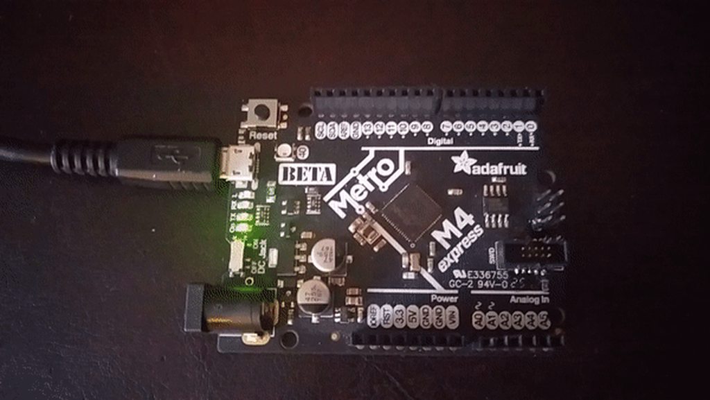
no blinka involved
exotic pumice
thanks to everyone that helped me get to this point
ruby atlas
For those of you that have been listening to me/watching me work on pixelbuf:
32 pixel array, Feather M4 - Runtimes in seconds for a 256 loop wheel():
neopixel.py brightness=0.1 7.31797
neopixel.py brightness=1.0 5.42851
encapsulated pixelbuf 1.75293 (python settem, getitem wrappers)
pixelbuf neopixel_write 1.69814
pixelbuf neopixel_write via python 1.68467
direct common_hal_neopixel_write 1.6835
I'm going to see how non-sliced setitem performs next. That may make the decision easier.
raven canopy
nicely done @ruby atlas! i envision many happy "blinka blinkers" when you're finished...
ruby atlas
animated blinkas i imagine
raven canopy
and...how is that not a team name i have heard of? "Our next competitors for the Annual Retinal Trickery Competition are...Blinka's Blinkers!"
upbeat plover
i like UART
exotic pumice
just looking at itsybitsy m4, very cool that swclk and swdio are first class pins
I gotta get me one of them
now I see why you guys mentioned the itsybitsy when I was looking into making a swd implementation
solar whale
@upbeat plover @raven canopy regarding the stacked feathers, it should be OK to stack SCK,MISO,MOSI -- they are a bus and are norammly shared amond all SPI devices. I'd look elsewhere for the conflict.
upbeat plover
it was SCK, i detached it and so far no further problems
solar whale
hmm -- I guess that makes sense now that you mention it -- only one board can provide the clock. wings dont do that. .. there is more to stacking feathers than meets the eye -- be careful out there....
upbeat plover
yes for sure, i was going to try m4 but couldnt even find good pair of pins for TX and RX
exotic pumice
@upbeat plover I think the same script for finding tx and rx would run on m4
upbeat plover
yeah it does, i mean pair for both boards that line up well when stacking
exotic pumice
oh I see
upbeat plover
Hallowing has accelerometer, TFT, and external si7021 sensor all going, sending; temp, humidity, x y z G, and Lightsensor analog value over UART to adalogger and adalogger puts that all in a txt file on SD card
really seems like its working so far
solar whale
@umbral dagger I tried to point this forum post you your blog about updating the feather M0, but the blog link is broken https://forums.adafruit.com/viewtopic.php?f=57&t=145597&p=719369#p719369 -- Do you want to comment on it?
umbral dagger
@solar whale Done. I seems to have not turned https support on when I changed hosting.
manic glacierBOT
just using a wire, but it needs to be stable no matter what the method - did you add a way to test with an optional charge gpio pin? that should work more consistantly :)
manic glacierBOT
 manic glacierBOT
manic glacierBOT
manic glacierBOT

 tough pier
So I'm new at this but not programming, I'm using a CPX and i want it to throw some keyboard commands when I hit real momentary pushbuttons so my F/A-18E's APU will be just like the real one. Anyway here's my code:
import time
import board
import digitalio
from adafruit_hid.keyboard import Keyboard
from adafruit_hid.keycode import Keycode
kbd = Keyboard()
apu = digitalio.DigitalInOut(board.A1)
apu.direction = digitalio.Direction.INPUT
apu.pull = digitalio.Pull.DOWN
while True:
if apu.value:
kbd.send(Keycode.A)
else:
print(apu.value)
time.sleep(1)
problem is all I get back is false.
I have a normally open momentary hooked to ground and A1
but oddly enough, if I take it to the REPL, I can get apu.value of false and I get true when I press it. I must be missing something real easy. Sure enough it was easy. Momentary switches need to be pulled up and then given an IF not statement instead. Like So:import time
import board
import digitalio
from adafruit_hid.keyboard import Keyboard
from adafruit_hid.keycode import Keycode
kbd = Keyboard()
apu = digitalio.DigitalInOut(board.A1)
apu.direction = digitalio.Direction.INPUT
apu.pull = digitalio.Pull.UP
while True:
if not apu.value:
kbd.send(Keycode.A)
time.sleep(1)
kbd.release(Keycode.A)
 light plaza
hello, if I have questions to the usage of a circuitpython-lib, where should I ask?
I try to run the example of the adafruit_lidarlite circuitpython lib, but the only thing I get, are exeptions. The LIDAR works with the Garmin Libs (and same wiring) without problems ...
solar whale
@light plaza this is the place to ask -- post your code and the error messages and people will try to help when they are online.
also let us know what microcontroller board you are using and what release of Circuitpython.
light plaza
Feather M4 Express, CircuitPython 3.1.1 with the Library-Bundle.
code (lidarlite_simpletest.py):
import time
import board
import busio
import adafruit_lidarlite
Create library object using our Bus I2C port
i2c = busio.I2C(board.SCL, board.SDA)
Default configuration, with only i2c wires
sensor = adafruit_lidarlite.LIDARLite(i2c)
Optionally, we can pass in a hardware reset pin, or custom config
#import digitalio
#reset = digitalio.DigitalInOut(board.D5)
#sensor = adafruit_lidarlite.LIDARLite(i2c, reset_pin=reset,
configuration=adafruit_lidarlite.CONFIG_MAXRANGE)
If you want to reset, you can do so, note that it can take 10-20 seconds
for the data to 'normalize' after a reset (and this isnt documented at all)
sensor.reset()
while True:
try:
# We print tuples so you can plot with Mu Plotter
print((sensor.distance,))
except RuntimeError as e:
# If we get a reading error, just print it and keep truckin'
print(e)
time.sleep(0.9) # you can remove this for ultra-fast measurements!
The error-Messsage(s):
Measurement failure
solar whale
@timber mango I don't see anything obvious -- hopefully some familiar with that sensor or the library will be online later. Do you have the RESET line wired in - Does the Garmin Software use that?
light plaza
@solar whale No, I do not have the reset-line wired in.
I have only the 5V, GND, SDA and SCL lines wired and I have attached two pullup-resistors to 3.3V and the capacitor, that the LIDAR manual shows.
If I use the same configuration for a L3GD20 sensor and change only the SDA and SCL wires, I2C works as expected with the circuitpython adafruit_l3gd20 -lib.
If I have the LIDAR wired and exchange the feather M4 with feather M0, that runs the Garmin Arduino Lib, the LIDAR works fine.
So it seems, that the only thing, that does not work, is the adafruit_lidarlite. But I cannot imagine this, because it would be the first time, that a adafruit - lib does not work ...
solar whale
@timber mango Is it a 5V device or 3.3V -- the Feather M4 expect 3.3V signals for I2C
light plaza
@solar whale It is a 5V device
does a M0 expect 5V?
and I have the pullup-resistors connected to 3.3V
solar whale
The M0 is also 3.3 V so I don;t know but I would be careful connecting a 5V device to either one. I'll defer to someone with more harware experience to comment. Good luck -- I see you also posted your question to the forum so I hope you get some help soon.
light plaza
Hm, but Adafruit is selling them (the Version without HP, that is 5V, too ) and they have a project (range finder), where they have wired it the same way as I do (even without pullups, but I have tried it without pullups, getting the same exceptions). And Adafruit is providing this lib.
It would IMHO make no sense, if they would sell hardware, provide a tutorial together with a lib, if it would not work from a power point of view, would it?
@solar whale and thank you for your comments
solar whale
@light plaza I don't work for Adafruit - I was just trying to help and as noted I don't see any obvious problem. Hopefully the people who provided the library can respond when they are online. Good luck!
tulip sleet
@timber mango Also feel free to ask in https://forums.adafruit.com, where paid technical support people hang out and can refer problems to the appropriate library writer.
light plaza
@tulip sleet yes, I already did, but there was no answer, so I had a look into the chat, if here is a better place to ask ... I am not that familiar with the many "channels" Adafruit offers to communicate to its customers ....
tulip sleet
@timber mango Could you give a link to your forum post? It can take a few days for a specialized response some time. Also, if you think there's a bug in the library, post an issue in its github repo. Discord is for more casual support and support by the community. Only a few of the support people monitor Discord
light plaza
@tulip sleet Ah ok, here is the link to my forum-post: https://forums.adafruit.com/viewtopic.php?f=60&t=145569
tulip sleet
@timber mango - it appears there are differences in the I2C details: http://blog.pistuffing.co.uk/garmin-lidar-lite-v3-vs-v3hp/
light plaza
@tulip sleet ok, thank you, so the lib has to be adapted to the new registers? that leads to my seconfd question on the forum, How to do that 😉
and what I do not understand in this case: Why is it possible, to use the same version of the official Garmin lib for both LIDARs and why do they not mention on their github page, that there are differnces .... but, I will have a deeper look at these registers, to compare them.
I actually did a quick comparison, but there it seems, that the registers are the same .... so I have to look more accurate .....
tulip sleet
@timber mango i think the regs are the same but the way they work is slightly different (based on that blog post above). The Garmin Arduino library probably handles both, but we don't (since we don't sell the V3HP and so didn't test against it).
there may be other clues in the vast internet, but that was the most promsiing link I found
umbral dagger
@light plaza I replied to the forum post. As for the issue of 5 vs 3.3. It just worked when I hooked it up. I had an I2C level convertor on hand in case it was needed, but it didn't seem to be. I never encountered any issue during coding, build, & testing.
@light plaza There's (in garmin/LIDARLite_Arduino_Library) actually separate libraries and examples for each model.
manic glacierBOT
 marble hornet
my dad is using windows 8, should he install the windows 7 drivers ?
for cirpy
**and the drive isn;t showing up as a serial device
idle owl
@marble hornet Yes.
marble hornet
Thanks
idle owl
At least I have had three people do that and it worked, but I still make no real guarantees.
ruby atlas
Apparently I'm going to need to trace execution to see where cycles are going. assignment of a single value (foo[n]) vs slicing is significantly slower than expected - worse than neopixel.py even. Except in one code path. Either way, I'd like to know why.
upbeat plover
@light plaza do you have one of these? https://www.adafruit.com/product/2465
the guild shows you need one to make 3.3v power 5v
https://learn.adafruit.com/garmin-lidar-lite-range-finder/hardware

PowerBoost 1000C is the perfect power supply for your portable project! With a built-in load-sharing battery charger circuit, you'll be able to keep your power-hungry project ...
Measure distances using lasers. LASERS! No sharks, though.
idle owl
<@&356864093652516868> Reminder: No Weekly meeting today! We won't be meeting again until 7 January 2019. Have a wonderful New Year!
marble hornet
awe
raven canopy
@idle owl i'm off today and tomorrow, if you want to chat cookie+pypi. @tidal kiln, @gusty kiln (and anyone else, really) would you be available & willing to participate? my only experience with the PyPi stuff is as a spectator, so your inputs would be helpful i think.
of course, i'll need to work out my mic issues from last week. 😄
idle owl
@raven canopy Tomorrow should work. Today I'm headed out after an already-scheduled meeting. I don't think the discussion will be that involved, I already know what we can add and what we can't. And the general cookiecutter issues aren't PyPI related, they're bugs.
light plaza
@upbeat plover hat I do not have such a PowerBosst Charger.
As far as I have understood the tutorial, I would need this, if I wanted to use a battery, but I do not want. "To make it mobile, we can use a LiPo battery and a PowerBoost to get 5v."
raven canopy
ahh. misunderstood (forgot?) the scope, maybe. just let me know...i have zero plans.
idle owl
@raven canopy Scope is we're adding as much of the PyPI stuff to cookie as possible to get it out of the way since basically everything is going on PyPI. And there are a couple of unrelated issues.
I'll ping you tomorrow!
light plaza
@tulip sleet if the registers are the same, do you have an idea, how I could find out, where exactly the differences are?
 jaunty hound
Does anyone out here have experience with the mcp9808 temperature breakout board?
idle owl
@raven canopy Or depending on when the meeting ends, maybe today, but probably not.
tulip sleet
@timber mango i would hope the data sheets show the differences (not necessarily explicitly). As @umbral dagger mentioned in the forum, it sounds like the Garmin-supplied drivers cover both V3 and V3HP, so that could could be taken as "truth". @umbral dagger said there are different versions for the two variants (? I haven't looked at the Garmin library)
marble hornet
does an open drian output mean it defaults to gnd?
raven canopy
@idle owl all good. we can just mark it for tomorrow...early dismissal from a meeting should never be rewarded with another meeting! 😜
idle owl
It almost always is 😃
raven canopy
troof.
tulip sleet
@marble hornet the drain is usually
yes, usually, the drain is on top and is "open" (not connectted to anything)
marble hornet
thank you
tulip sleet
(picture is from elsewhere, not wikipedia article)
 tough flax
Finally getting back into the serial comm issues - holidays took me out.
light plaza
@tulip sleet ok, after looking into the zip file, I saw, that there are indeed two versions, one is called LIDARLite and one is called LIDARLitev3HP ... so - as you said - inside of them must be the truth 😉
tough flax
@tulip sleet I've added debugging at the Python level - basically its never returning from input() when the string is sent from the command line (via echo)
From minicom it does... that will push me to look at how we're calling the readline lib...
umbral dagger
@light plaza Between the Garmin libs and datasheets, it should be easy to create a 3HP module.
idle owl
@tough flax We're in a meeting for a bit here, fyi. So there will be a bit of a delay in response.
tough flax
Sorry - didn't realize
idle owl
No worries! Simply letting you know so you're not wondering 😃
upbeat plover
@marble hornet you still working on that mini M4?
marble hornet
yeah
upbeat plover
i kinda want one
marble hornet
what do you wanna use it for?
upbeat plover
nothing special just shrink a project
upbeat plover
that's pretty cool, how many you get made at a time? do you do a whole bunch to check manufacturing process is good?
tough flax
@tulip sleet @tidal kiln @idle owl I am not sure this is a CP issue, so I created an issue in my client code repository to track the analysis on this - we can move results over https://github.com/ATMakersOrg/Little-HandRaiser/issues/1

GitHub
I thought I'd make a place to store the progress on this - I'm not sure it's a CircuitPython issue yet. The problem is that when trying to send data to CP from linux, the input() method...
 carmine kestrel
greetings
i have a question
i want to have the itsy bitsy m0 provide a raw bytestream over usb since i need a fairly high bitrate for something
500+ kb/s
upbeat plover
i think USB is limited to 115200?
raven canopy
@carmine kestrel i can't give any concrete yes/no on possibilities; my understanding isn't strong enough to be definitive. however, here are some things to consider. the M0/M4 are USB Full Speed compliant, which means theoretically the bitrate is 12Mbps; practical speed is much less (1-9Mbps based on googling, with most results in the lower range).
if you are using CircuitPython, i don't recall a method to send a data stream through USB; only to capture receiving it using input(). (someone please correct me if i'm wrong on this.) the only real option is to use an external UART-to-USB converter, and use busio.UART. there is also USB HID support, but that would most likely be quite limiting since you'd have to convert data to keycodes/etc and parse it on the PC side.
Arduino may have better options, with the use of Serial \ Serial1. i haven't really used Arduino in quite some time, so i can't help at all on that front.
carmine kestrel
i was hoping since it had the HID capability i could pretend to be some other USB device
modem ? or perhaps audio or so on
to the stream the data that way
long as i can open the raw stream PC side before a decode
raven canopy
well, there is HID Consumer Control. but, if you were planning that, then i guess you already thought about intercepting and parsing on the PC side.
carmine kestrel
i should then be able to implement a custom decoder to pull out my data
 timber birch
Humble has a new python bundle out.. I posted the link in books
carmine kestrel
HID doesn't seem the right overall choice though since it's ISR driven handling in the OS with limited to 0 buffering
there is already uart over the usb but i'd need it to run @ 1 Mb/s ish and i don't know if it will let me
raven canopy
yeah, i agree. iirc there is an open issue for (re)implementing multi-terminal, but not completely sure that would allow this. and, i'm fairly certain there hasn't been any movement on it.
carmine kestrel
best idea was to present as an microphone
and then open that
and then take the bytestream and re-interpret
BUT i'd have to know how to present as a microphone vs HID
raven canopy
@tulip sleet did most (all?) of the HID work. he would know best if that can be extended.
carmine kestrel
ok
technically it's 5 microphones but i can interlace them in one stream so no big deal
TY though 😃
marble hornet
does anyone know a board house that will also populate boards ?
exotic pumice
it's called pcba or pcb assembly. SeeedStudio is one.
pcba is rather expensive though
PCBWay is another popular one.
 prime flower
microfab
stuck elbow
https://pcbshopper.com/ <-- click the "assembly" tab

PCBShopper is a price comparison site for printed circuit boards. Enter your PCB's specs and immediately see prices from more than 20 PCB manufacturers.
there are many more, for example elecrow is not listed there, that's where I assemble mine
marble hornet
thanks !
manic glacierBOT

 pliant pond
Happy New year everyone! I was wondering if there was anHTTP client library in circuitpython (Need to make a simple POST to a webservice)?
 inland tusk
HAPPY NEW YEAR, Hope everyone has prosperous 2019 to come.👌
Charles
prime flower
@inland tusk you too!!
@pliant pond no httpclient yet, it's still early but you can connect to the internet using this guide https://learn.adafruit.com/adding-a-wifi-co-processor-to-circuitpython-esp8266-esp32
Surf the 'net with Blinka!
pliant pond
Thanks for answering! I was just hoping for some of the encoding to be offloaded to smarter brains than mine 😄
inland tusk
@prime flower Brent hope you have one too
tough flax
@tulip sleet @tidal kiln I have an update - basically two things have to be true to get input() to return and provide data (at least when the client's linux). 1) You must send a carriage return (\r) - Minicom does this and echo does not. and 2) you must read from the socket (from the linux side).
So, the following works:
$ printf "red\r" > /dev/ttyACM0
$ cat /dev/ttyACM0
The only problem I've found is that cat never returns (neither does tail which I found surprising). I also learned that there's basically no way to make echo send a \r consistently, but the bash builtin printf does fine.
This command works exactly as I'd like :
printf "@wheel\r" > /dev/ttyACM0 ; head -1 /dev/ttyACM0 > /dev/null
Still would love to know why I have to read the stream to get it to act, but I'm not complaining - I have a solution 😃
exotic pumice
How does one "step over" a line in gdb? ie go to the next line, not jump into the function call
exotic pumice
thanks
tough flax
Or launch it from emacs & you'll get a menu & lots of goodies (my first IDE was Emacs + GDB)
umbral dagger
@tough flax Anything with text I usually use GNU Emacs.
manic glacierBOT
upbeat plover
is the CPX sound sensor SPW2430?
light plaza
@tulip sleet , @umbral dagger , thanks for you hints, I got it working now.
ruby atlas
ha, oops, just called a file neostar.py and another dotpixel.py
raven canopy
@ruby atlas better than neodot.py and pixelstar.py, right?
upbeat plover
took me bit but added sound sensor to cpx frozen lib
just does dB
cpx.magnitude
everything was from here https://learn.adafruit.com/sensor-plotting-with-mu-and-circuitpython/sound

Plot all the things!
hmm i guess it isnt dB at least it's no where near the same as my multimeter, but does reflect how loud sound is
raven canopy
@terse bay moving over from #help-with-projects, what OS are you on and which version of CircuitPython are you running?
 terse bay
Alrighty, this looks like the proper forum for my question:
I am fairly versed in MATLAB and ARDUINO coding, but have taken on the side project of learning CIRCUITPYTHON by building a neotrellis toy. I have a Feather M0 Exprtess built and functioning and am currently working on the code for a Simon-like sequential memory game. I am building it off of the simple Neotrellis Example file. My question is this: How do I edit and save .mpy files? I am using MU as my editor and it doesn't seem compatable. Ive searched quite a bit to no avail. THANKS!!!!!
im on windows 10, CP version 3.x.x
im at the gym on the treadmill lol, if you need the actual version I can post in a bit when I gewt home
light plaza
@terse bay as far as I have understood this, you cannot edit the *.mpy files
raven canopy
Actually, let me back up a minute.
How do i edit and save .mpy files?
.mpy files cannot be edited. they are .py files that have been converted to bytecode, using the mpy-cross utility. so, you'll have to edit any .py files, then run mpy-cross to convert them. here is a link to download mpy-cross 3.x for windows: https://github.com/adafruit/circuitpython/releases/download/3.1.1/mpy-cross-3.x-windows.exe
light plaza
you have to edit *.py files and use a "cross-compiler", to "compile" *.mpy out of them
raven canopy
@terse bay are you trying to edit a library/etc that was downloaded, or your own local files?
terse bay
oh ok, that's silly, but I think I understand. So in order to get into Imported files from an example code, and tinker with them ( that seems to be how I learn best what things do), I need to pull it off the GitHub, save it as a .py file and put that in the lib folder on board, then I can edit it? must I also delete the original .mpy that im tinkering with?
can I import .py files exactly the same way as I have been with .mpy files?
raven canopy
@terse bay you can download the .py bundle, as opposed to one-at-a-time.
and yes, .py imports the same. however, memory issues can arise depending on the size of the file. CircuitPython does the bytecode conversion of .py files internally, but that takes up additional RAM space. that is why using .mpy is recommended (required in some cases).
upbeat plover
@raven canopy https://cdn.discordapp.com/attachments/327298996332658690/529493911924768778/express.py is line 109 needed?
the actual property is down at line 506
or maybe @idle owl could help
terse bay
@raven canopy Ya i have the current pi bundle for version 3.x.x . and sounds good, thanks. I suppose I will go ahead and learn how to use mpy cross, I guess it will be handy eventually .
raven canopy
@upbeat plover its possible that the instance variable could be removed, and have the property just return the math.sqrt result. i don't see anywhere else that the instance variable is used...
upbeat plover
thank you, removing it should free up a tiny bit of ram?
raven canopy
tiny...yes. wouldn't expect much savings, if its even noticeable. 😉
upbeat plover
    @property
    def magnitude(self):
        samples = array.array('H', [0] * 160)
        self._sound.record(samples, len(samples))
        minbuf = int(sum(samples) / len(samples))
        sum_of_samples = sum(float(sample - minbuf) * (sample - minbuf)
            for sample in samples)
        return math.sqrt(sum_of_samples / len(samples))
does that look correct?
raven canopy
yep
upbeat plover
after loading adafruit_circuitplayground.express has like 22kbs of ram
raven canopy
well, on the CPX that library is frozen in. are you updating the frozen lib? that may complicate your comparisons, if not.
upbeat plover
yeah also i have to load gc so not just express is being loaded
manic glacierBOT
 upbeat plover
this was my memory test
`>>> import gc
gc.mem_free()
22256
gc.collect()
gc.mem_free()
22208
gc.collect()
gc.mem_free()
22176
gc.collect()
gc.mem_free()
22144
from adafruit_circuitplayground.express import cpx
gc.mem_free()
11408
gc.collect()
gc.mem_free()
11504
cpx.magnitude
48.4383
gc.mem_free()
10144
cpx.magnitude
131.216
gc.mem_free()
8784
cpx.magnitude
75.0965
gc.mem_free()
7424
cpx.magnitude
60.0724
gc.mem_free()
6064
cpx.magnitude
58.9491
gc.mem_free()
4704
cpx.magnitude
48.5408
gc.mem_free()
3344
cpx.magnitude
53.6286
gc.mem_free()
1984
cpx.magnitude
63.8343
gc.mem_free()
11616`
looks like gc.collect() is not needed and i only have 11kbs not 22kbs
raven canopy
the garbage collection will eventually toss out stuff; gc.collect() just forces it.
upbeat plover
so i do need to import it to do the auto collect?
raven canopy
nope. well, there are instances in code where forcing it is useful.
upbeat plover
smaller samples seem better when trying to use as "the clapper"
upbeat plover
I'm not sure how to do github but I think this needs to be verified. https://github.com/adafruit/Adafruit_CircuitPython_CircuitPlayground/commit/c377b39ba584cf03d734f228ec7a3855f5fb12eb

do i click the "Create pull request" button?
im gana click it
 terse kayak
Yes, that puts it in for approval
 acoustic pollen
is it possible/okay to change the usb label name of a circuitpython cpx so that it works with devices that only work with certain labels on a usb device?
upbeat plover
maybe this? im not sure never tried
GitHub
CircuitPython - a Python implementation for teaching coding with microcontrollers - adafruit/circuitpython
tawny creek
@acoustic pollen like “CIRCUITPY” to something else?
ruby atlas
if the volume name, yes, it's in filesystem.c line 66 https://github.com/adafruit/circuitpython/blob/master/supervisor/shared/filesystem.c#L66
GitHub
CircuitPython - a Python implementation for teaching coding with microcontrollers - adafruit/circuitpython
upbeat plover
thats probably what he means
acoustic pollen
ywah
*yeah
is it possible to do it from windows itself when it's plugged in or does it need to be special built?
ruby atlas
special build.
tawny creek
@ruby atlas @acoustic pollen Idk if this is a bug, but I just tried renaming "CIRCUITPY" to "CIRCUITPY2" in Windows 10 and Mojave with no issues
(on 4 alpha 5)
ruby atlas
May be fine, but I bet it returns as CIRCUITPY if you reconnect.
tawny creek
not true, it retains the new name
upbeat plover
does it have new name on other devices?
ruby atlas
Let me pull out my laptop
tawny creek
only tested on windows and mac
ruby atlas
yep retained on mac between systems
tawny creek
maybe a perk of Tinyusb ? hm
ruby atlas
there's undoubtedly code someplace to save that to flash
upbeat plover
thats cool
ruby atlas
/dance
meager fog
does it work if you then take that to another computer?
ruby atlas
Yep
I moved it to my other mac.
Now I know which one is my Feather M4 and which is the Metro M4
tawny creek
@meager fog @ruby atlas only discovered this by mistake 😄
meager fog
it didnt used to work
ruby atlas
STATIC mp_obj_t vfs_fat_setlabel(mp_obj_t self_in, mp_obj_t label_in) { ... well that'll help 😃
manic glacierBOT
this apparently works now - and quite well! handy when you have many circuit py boards :) find a good spot in the essentials? maybe early on cause its useful for classrooms!
ruby atlas
Should failing to upload artifacts cause a PR to fail Travis?
(IMO it shouldn't be trying)
hearty edge
Happy New Year! Still working with I2C registers. Trying to modify MCP9808 code from https://learn.adafruit.com/circuitpython-basics-i2c-and-spi/i2c-devices
Trying to change the resolution by setting register address 0x08 to value 0x0. The code I am using is below. The three commented lines in the while loop was my latest attempt.
import board
import busio
import time
i2c = busio.I2C(board.SCL,board.SDA)
def temp_c(data):
value = data[0] << 8 | data[1]
temp = (value & 0xFFF) / 16.0
if value & 0x1000:
temp -= 256.0
return temp
while not i2c.try_lock():
pass
while True:
i2c.writeto(0x18, bytes([0x08]), stop=False)
resolution = 0x0
i2c.writeto(0x18,resolution,stop=False)
i2c.writeto(0x18, bytes([0x05]), stop=False)
result = bytearray(2)
i2c.readfrom_into(0x18, result)

tempC = temp_c(result)
tempF = tempC * 9 / 5 + 32
print('Temperature: {} C {} F '.format(tempC, tempF))
time.sleep(1)

Learn how to talk to I2C and SPI devices with CircuitPython!
tawny creek
hm @hearty edge if you wrap your code in ``` it'll format it to code for easier viewing
hearty edge
@tawny creek thanks for the tip!
import board
import busio
import time

i2c = busio.I2C(board.SCL,board.SDA)

def temp_c(data):
    value = data[0] << 8 | data[1]
    temp = (value & 0xFFF) / 16.0
    if value & 0x1000:
        temp -= 256.0
    return temp


while not i2c.try_lock():
    pass

while True:
    i2c.writeto(0x18, bytes([0x08]), stop=False)
    resolution = 0x0
  # i2c.writeto(0x18,resolution,stop=False)
    i2c.writeto(0x18, bytes([0x05]), stop=False)
    result = bytearray(2)
    i2c.readfrom_into(0x18, result)

    tempC = temp_c(result)
    tempF = tempC * 9 / 5 + 32
    print('Temperature: {} C {} F '.format(tempC, tempF))
    time.sleep(1)
@ruby atlas that build is failing on the Building Translations. need to run a make translate then commit that. i'm peaking at the reason for artifacts; there's no cron but i imagine its for the nightly S3 build.
ruby atlas
aha! i missed that failure.
hearty edge
This has the comments in the correct locations
import board
import busio
import time

i2c = busio.I2C(board.SCL,board.SDA)

def temp_c(data):
    value = data[0] << 8 | data[1]
    temp = (value & 0xFFF) / 16.0
    if value & 0x1000:
        temp -= 256.0
    return temp


while not i2c.try_lock():
    pass

while True:
 #  i2c.writeto(0x18, bytes([0x08]), stop=False)
 #  resolution = 0x0
 #  i2c.writeto(0x18,resolution,stop=False)
    i2c.writeto(0x18, bytes([0x05]), stop=False)
    result = bytearray(2)
    i2c.readfrom_into(0x18, result)

    tempC = temp_c(result)
    tempF = tempC * 9 / 5 + 32
    print('Temperature: {} C {} F '.format(tempC, tempF))
    time.sleep(1)
And yeah, i'm sure it's the nightly S3 stuff, but that was just misleading I think.
acoustic pollen
im missing the adafruit_circuitplayground.express library. where would i re-get it
upbeat plover

How to build CircuitPython yourself on different platforms
acoustic pollen
i don't see anything related to re-downloading the lib in there
upbeat plover
git pull
git submodule sync
git submodule update --init --recursive
# Then make again.
for updating but i usually just delete the whole circuitpython and git clone
if i have changes i keep them backed up somewhere else
acoustic pollen
is there a way to re-install the library just with a folder or is it unique to every cpx board?
upbeat plover
if your trying to change frozen lib adafruit_circuitplayground.express library you have to rebuild and then use new uf2 file
im not sure how its "missing"
raven canopy
@acoustic pollen the library is "frozen into" the CPX firmware. if importing it is failing, then the file system may be corrupt.
idle owl
@upbeat plover I replied to your PR on GitHub. Unfortunately we won't be able to add the feature to the library. It's already almost too big. The buffer required to do sound sensing causes memory allocation failures consistently as soon as any other code is added to a program. It runs fine alone, but if you add any other features to your program, it begins to fail.
We tried before, I have the code already written to add it. 😃 But until there's an update to how memory is handled or physically to the CPX, it isn't viable.
acoustic pollen
for some reason the keyboard feature isnt working on circuitpython on the cpx
from the make it a keyboard guide
upbeat plover
@idle owl can i get an example of a failer? cause im not seeing any issues yet and only diffrence is 176 bytes when importing cpx
I believe you i just would like to understand it.
idle owl
@upbeat plover I can in a bit. It was failing when you started to add other things like NeoPixel or light sensor or some other feature of the lib. Like, if loud_sound() (which was simply a threshold check), turn on NeoPixels or something like that.

 craggy harbor
Why are the A0 and A1 pins on the Feather M4 marked with brackets on the PCB? Can I use them like regular digital pins?
 floral panther
NEW YEAR'S DAY 2019 - GitHub stars live @adafruit @github #adafruit #github #circuitpython-dev https://youtu.be/ZLSLhEF9ShI & https://github.com/adafruit/circuitpython

GitHub
CircuitPython - a Python implementation for teaching coding with microcontrollers - adafruit/circuitpython
 main meteor
I think it's because they offer DAC functionality. I believe you can still use them as digital IO pins.


 floral panther
GitHub
CircuitPython - a Python implementation for teaching coding with microcontrollers - adafruit/circuitpython
manic glacierBOT


Message:
You are running in safe mode which means something unanticipated happened.
Looks like our core CircuitPython code crashed hard. Whoops!
Please file an issue at https://github.com/adafruit/circuitpython/issues
with the contents of your CIRCUITPY drive and this message:
Crash into the HardFault_Handler.


 upbeat plover
@idle owl i found a crash when doing
from adafruit_circuitplayground.express import cpx

while True:
    if cpx.magnitude > 400:
        cpx.play_file("electrons.wav")
that crashs circuitpython and causes safe mode, even if you have a sleep at the end of file play but
from adafruit_circuitplayground.express import cpx
cpx.play_file("electrons.wav")
cpx.magnitude
cpx.play_file("electrons.wav")
cpx.magnitude
runs without crashing
everything else seems to work in the cpx lib
manic glacierBOT
 upbeat plover
from adafruit_circuitplayground.express import cpx
import gc

while True:
    gc.collect()
    if cpx.magnitude > 400:
        cpx.play_file("electrons.wav")
no crash so everything does work fine
@raven canopy this is where the gc.collect() was useful

 upbeat plover
from adafruit_circuitplayground.express import cpx
import gc

cpx.pixels.brightness = 0.3

while True:
    gc.collect()
    if cpx.magnitude > 400:
        x, y, z = cpx.acceleration
        print(x, y, z)
        cpx.red_led = True
        print(cpx.touch_A1)
        print(cpx.touch_A2)
        print(cpx.touch_A3)
        print(cpx.touch_A4)
        print(cpx.touch_A5)
        print(cpx.touch_A6)
        print(cpx.touch_A7)
        print(cpx.button_a)
        print(cpx.button_b)
        cpx.pixels[9] = (30, 0, 0)
        cpx.pixels[8] = (30, 0, 0)
        cpx.pixels[7] = (30, 0, 0)
        cpx.pixels[6] = (30, 0, 0)
        cpx.pixels[5] = (30, 0, 0)
        cpx.pixels[4] = (30, 0, 0)
        cpx.pixels[3] = (30, 0, 0)
        cpx.pixels[2] = (30, 0, 0)
        cpx.pixels[1] = (30, 0, 0)
        cpx.pixels[0] = (30, 0, 0)
        print("Lux:", cpx.light)
        print("Slide switch:", cpx.switch)
        temperature_c = cpx.temperature
        temperature_f = temperature_c * 1.8 + 32
        print("Temperature celsius:", temperature_c)
        print("Temperature fahrenheit:", temperature_f)
        print("free mem:",gc.mem_free())
        gc.collect()
        print("free mem:",gc.mem_free())
        cpx.play_file("electrons.wav")
        print("free mem:",gc.mem_free())
this works, so calling everything from a loud_sound() seems fine
manic glacierBOT
upbeat plover
added si7021 too and still has lots of memory, but i cant use touch_a4 or touch_a5 with the si7021 sensor thats unrelated to cpx.magnitude has to do with scl and sda
idle owl
We can't instruct people to include garbage collection in cpx lib projects - it's meant to be simple and for beginners.
upbeat plover
i was thinking that so im trying a build with express.py with it included lol
exotic pumice
new org for Rust neopixels
https://github.com/smart-leds-rs
https://i.imgur.com/GHFuPLF.jpg

GitHub
WIP Organization for drivers, effects and similar stuff with smart (addressable) leds - smart-leds-rs
it's supposed to be a smiley face
I'm not that great at neopixel demos haha, and I'm not sure if my library is even stable enough to do anything more than that
idle owl
@upbeat plover I appreciate your enthusiasm! The problem is that memory usage isn't always consistent, so even with gc.collect() included in express.py, we're still opening things up to potential failures. Like I said, the library is already massive. The amount of space left over after import is less than we'd like to have already. sound_level() requires a buffer. The difference between what I have written and what you wrote is that your buffer is half the size of mine - mine was 160 bytes which is what was used in the Sound Meter demo. It's possible that you're running into less issues than I did due to that difference.
but even losing 80 bytes to the buffer for your magnitude is not ideal.
I'm willing to test what you come up with, but I'm really not sure it's viable with the current environment.
upbeat plover
alright, im still gana give it a shot cause CPX "the clapper" is nice
idle owl
If we decide to include it, we can reopen your PR and make changes there (there are a few things that would have to change for backwards compatibility and to fit with the library design)
I agree! That's why I tried to add it. I like the idea of having as much of the functionality on the board in that library as possible.
The last two things are sound and IR. Both are massive unfortunately.
upbeat plover
yeah IR need much bigger buf

 marble hornet
hey, i've never actually needed to use on chip pullups but can an input be pulled up without an on board resistor?

 prime flower
@marble hornet yep - https://circuitpython.readthedocs.io/en/3.x/shared-bindings/digitalio/Pull.html
marble hornet
thnx
manic glacierBOT
 upbeat plover
@idle owl i tried hard to get it to work but even after i add gc and gc.collect() to the play_file and magnitude
from adafruit_circuitplayground.express import cpx

while True:
    if cpx.magnitude > 500:
        cpx.play_file("electrons.wav")
still crashes
from adafruit_circuitplayground.express import gc, cpx

while True:
    gc.collect()
    if cpx.magnitude > 500:
        cpx.play_file("electrons.wav")
doesnt crash... something weird is going on i dont understand
manic glacierBOT
 manic glacierBOT


Thanks. Could you be more explicit? Is this on a Hallowing or some other board? Did you alter the original demo program or is it unchanged? Are you still having trouble?
manic glacierBOT
 manic glacierBOT

>>> class A:
...     def __new__(cls):
...         super(A, cls).__new__(cls)
...
...
...
>>> a = A()
Traceback (most recent call last):
  File "<stdin>", line 1, in <module>
  File "<stdin>", line 3, in __new__
AttributeError: 'super' object has no attribute '__new__'
Is this feature implemented?
manic glacierBOT
 manic glacierBOT

 regal juniper
Hello all, I am new to this and I am working with Itsy Bitsy controller, I just want to know up to what extent I can work with Circuit Python. Can I do a commercial project using circuit python.?
manic glacierBOT
 regal juniper
I am trying to install circuit python on my board as per the instructions on the website, green led keeps on blinking and the drive with circuit python never comes.
marble hornet
@regal juniper cp i believe is under the mit license so:
https://opensource.org/licenses/MIT
what exact version of the itsy bitsy do you have? (is the board black?)
regal juniper
I am using one with cortex m4.
regal juniper
Yes I tried with different cables.
marble hornet
okay so no drive of any kind showed up?
regal juniper
Nope.
regal juniper
Itsy bitsy drive was there but when I uploades the circuit python file everything disappeared and a green light is continously blinking on the board.
I have tried uaing different operating systems and computets but the issue persists.
stuck elbow
which image did you flash?
marble hornet
can you get the boot-loader to appear again?
regal juniper
This one.
Yes I can get the boot-loader appear again by pressing the reset button twice.
regal juniper
Tried it but same issue.
manic glacierBOT
 regal juniper
Windows 7 and windows 10
 tall sand
Happy New Year! I can haz a BLE MESH wrapper in CircuitPython plz? https://www.nordicsemi.com/Software-and-Tools/Software/nRF5-SDK-for-Mesh
The nRF5 SDK for mesh is ideal for developing applications that use Bluetooth mesh networks . It is a richly featured SDK for building sophisticated solutions with Bluetooth mesh.
regal juniper
I am on windows 7 currently.
I have installed Adafruit drivers, are there some else.
marble hornet
okay,... it should be these:
https://learn.adafruit.com/welcome-to-circuitpython/installing-circuitpython

New to CircuitPython? This is the place to start.
GitHub
All in one Windows driver installer for Adafruit's boards. - adafruit/Adafruit_Windows_Drivers
regal juniper
Yes, I have installed these too.
marble hornet
i'm thinking...
can you try installing once more, just incase (i had to only check the top line to get them to work on win8 )
stuck elbow
since bootloader appears, the cable is not power-only
marble hornet
so it's probs sw thing right? (on one side or another)
regal juniper
I don't get it.
marble hornet
becasue the bootloader shows up that means there is a data connection. that means the problem isn;t in connecting to teh board it is software problem
did cp work before the update?
(please excuse the spelling)
regal juniper
The thing is I have had developed a custom board with some other modules on it along with Itsy bitsy controller. While designing I followed the schematics of Itsy Bitsy controller. When the board arrived, I burned the bootloader using Jlink and now trying to install cp but coming up with the issue.
Cp never worked.
marble hornet
so it isn't a from adafruit board? but the same pinout ?
is there a flash chip on the board?
marble hornet
is there a GD25Q16C on the board?
and i'm just curious are those 0402?? really cool!
regal juniper
yes these are 0402, I doubt the existance of GD25Q16C
marble hornet
ah okay, so the itsy m4 board has that built in. it is where the files are stored
@stuck elbow is there enough space for an m4 with internal flash as the drive?
regal juniper
3.87 MB
marble hornet
where do you see that?
regal juniper
The drive with label ITSYM4Boot.
marble hornet
i see that on my m4 board too, but that doesn;t necessarily mean that there is 3.xx mb of flash
i think, if you don'y have external flash connected to the atsam51, you will need to make a custom board file for your device which uses the internal flash as the drive
regal juniper
The reason I am trying for cp is that I want to configure sercomm ports as serial ports. Is there any way around? Can I do it using Arduino IDE?
marble hornet
i don;t have the expertise but plenty of the cp helpers can help with the board configuration. (it isn't too complicated) i've done it, just not enough to show someone how
and i'd ask in #help-with-projects about that in arduino
marble hornet
are you familiar with github?
manic glacierBOT
It is for the Hallowing.
Running the latest version of the 4.00 Alpha
I attached a Bluefruit LE UART Friend [2479] to the pins on the back to try working with bluetooth.
I'm working on a custom program from that has the intention of running a neopixel strip in a pattern that can be changed by an app on my phone via the bluetooth.
The zip file in the original contains the code file which caused the error.
The board runs a simple program so tonight I'm going to try rebuilding the progra...
marble hornet
i do know it isn't that difficult you just need to know what to do, i suggest askig someone with more experience then i.
regal juniper
Yes I am.
marble hornet
okay, so you'll need to clone the cp repo then in ./ports/atmel-samd/boards duplicate and rename the itsy m4 folder then the changes will be made in there
GitHub
CircuitPython - a Python implementation for teaching coding with microcontrollers - adafruit/circuitpython
regal juniper
Thank you.
manic glacierBOT
 prime flower
@solar whale did you use a jlink to flash the particle with ?
or is there another way to get circuitpython loaded on there, like the uf2x sketch
solar whale
@prime flower yes -- flash bootlader,sd then CP
jlink only for bootlader and SD -- uf2 for CP
manic glacierBOT
 solar whale
I think you need to put our bootloader on it first -- needs J-Link
manic glacierBOT
 solar whale
@prime flower here is what I did - using J-Link -- cloned the nrf bootlader https://github.com/adafruit/Adafruit_nRF52_Bootloader, then ```in projects/adafruit_github/Adafruit_nRF_Bootloader
make BOARD=particle_argon clean
make BOARD=particle_argon
make BOARD=particle_argon erase
make BOARD=particle_argon sd
make BOARD=particle_argon flash
copy CP .uf2 to CIRCUITPY
same for particle_xenon
@prime flower I am not familiar with what you refer to as the uf2x sketch -- I don't know if a stock particle board can be uploaded to by arduino or not -- iI have not tried that.
prime flower
was referring to https://github.com/adafruit/uf2-samdx1, but I'm following along with the nrf52 bootloader rn
solar whale
@prime flower try this link https://www.nordicsemi.com/Software-and-Tools/Development-Tools/nRF5-Command-Line-Tools
The nRF5 Command Line Tools are used for development, programming, and debugging of Nordic Semiconductor's nRF51 and nRF52 Series SoCs (System on Chip).
prime flower
yep that works, adding to my path
manic glacierBOT


__new__ requires MICROPY_CPYTHON_COMPAT which is only enabled on samd51/M4 builds (maybe on NRF but definitely not samd21/M0) due to the increased flash usage. See #1167.
solar whale
@prime flower let me know if it works OK -- I have not upgraded to the latest nrfprog so will wait until you confirm before I do 😉
manic glacierBOT
@dhalbert @tannewt if either of ya can verify this (i believe its true) then @kattni please add to the Expectations page :)
solar whale
@prime flower Nice! I don't think Mu is particle aware yet --- not sure how to get it there...
prime flower
fairly quick flash -> install, but I had the arm toolchain already installed
solar whale
yeah -- it was quick and easy for me.
prime flower
Download the ESP32 firmware bundle above, unzip and place the esp folder in the root directory of your CIRCUITPY drive alongside adafruit_miniesptool.py
@solar whale do you mean, keep miniesptool in CIRCUITPY instead of lib/
oh you didnt write that part, whoops
solar whale
oops -- missed that -- if you have miniesptool in the lib, then no need to copy it over again
prime flower
ESP32 mini prog
Resetting
Traceback (most recent call last):
  File "code.py", line 25, in <module>
  File "/lib/adafruit_miniesptool.py", line 448, in sync
RuntimeError: Couldn't sync to ESP```the guide still needs some clean-up