#circuitpython-dev
1 messages · Page 78 of 1
 fleet hollow
 blissful pollen
I'll look at the distortion PR first for sure. And I agree it may be easier to squish the audio to mono at the end vs handle it everywhere. The smaller boards are not using any crazy audio processing anyways.
I do wonder also is 8 bit being use that much either.
 onyx hinge
Howdy folks. I have some big news: In 2025 I'm finishing up my work at Adafruit. I'm not quite comfortable calling it "retirement", but we'll see what the future brings. https://social.afront.org/@stylus/113691513879680883
My #CircuitPython2025 @adafruit@mastodon.cloud
I’m not going to bury the lede: 2025 is the year I’m hanging up my hat as a core developer of CircuitPython. My involvement with Adafruit & CircuitPython will change from what it has been to just an occasional project. For that reason, this post is more about expressing my gratitude for the past an...
blissful pollen
onyx hinge
Howdy folks. I have some big news: In 2025 I'm finishing up my work at Adafruit....
First off congratulations, I know how tough a decision ones like this can be. I am also jealous of the travels you will have in April.
Thank you for all your contributions and help over the years since I joined. I cannot count how many times I saw something you were working on and went "wow cool" to myself.
onyx hinge
I appreciate hearing that, @blissful pollen
 manic glacierBOT

 manic glacierBOT

CircuitPython version
Adafruit CircuitPython 9.2.1 on 2024-11-20; M5Stack Timer Camera X with ESP32

Board ID:m5stack_timer_camera_x
Code/REPL
import busio
import board
import espcamera
i2c = busio.I2C(scl=board.SCL, sda=board.SDA)
data_pins=[board.D2,board.D3,board.D4,board.D5,board.D6,board.D7,board.D8,board.D9]
c = espcamera.Camera(data_pins=data_pins,pixel_clock_pin=board.XCLK,vsync_pin=board.VSYNC,href_pin=board.HREF,i2c=i2c,pixel_format=espcame... manic glacierBOT

I've done some more testing with both the CYW43439 on the Pico W boards and the RM2 module.
The older CYW43439 operates as described in the Cypress Semi datasheet. It does not change gSPI data phasing at lower clock rates.
The newer RM2 modules change gSPI data phasing somewhere between 21.429MHz and 23.077MHz on the two RM2 modules I tested.
Assuming a 150MHz processor clock, a divisor of 3 results in a 25MHz gSPI clock. Depending on the accuracy of the RM2's gSPI clock measurement,...
manic glacierBOT

Thanks for digging so deep into this @eightycc!
manic glacierBOT

I discovered that when a Metro M4 and Metro M7 are running the same code which acts upon a fixed period of time passing (measured by calls to time.monotonic()), my newly purchased M7 claims the time period has completed in only ~85% of the real time required by the M4. Both are sending begin and end messages via serial to a Raspberry Pi 400 which is listening to the serial via another Python code which measures the elapsed times. The Metro M4, as well as a Trinket M0, Gemma M0, and Circui...
manic glacierBOT
Do you have any other non-RP2040 CircuitPython boards to try, to see if they produce the same result or show the correct frequency?
 jaunty juniper
@willow totem I see you added Circuitpython and tinyuf2 PIDs for the Lilygo T-QT [pro] to the Espressif usb-pids repository (around 2023), but the board is not implemented in CP or tinyuf2 that I can see.
I have a T-QT pro (N4R2) and was preparing to PR it to both repos, I think I can use those PIDs then ?
I also implemented the N8 model though I can't test it, but there isn't much difference anyway (I followed the QTPY S3 which have the same variants). I believe they can share the same PID.
(these PIDs https://github.com/espressif/usb-pids/pull/80)
 willow totem
Yeah think that should be totally fine, but verify they're correct, I was on a t-displayS3 and t-qt mission at the time (its a t-qt pro I have too)
oh sorry, vid/pid mad, I've no idea what I'm saying, it's 1am here and I've had a bit of pub time
Thanks for your websockets lib too, recently had to use it for an RC joystick to RC forklift 😁 (still unfinished like so many things - but works)
jaunty juniper
oh nice, I think I might want to look into using ConnectionManager in the future
willow totem
Just reread the PR, yeah that should be fine
I wondered about exposing some timeout stuff, but otherwise nothing came up, it just mostly worked
jaunty juniper
I'm getting back on the Circuitpython saddle after a long time away and I have so many projects I want to update 😛
willow totem
Oh exciting, you bring some interesting things usually, I often find myself down similar paths that you've already beaten/trodden
Oh I might have already done half the work for the t-qt, you might want to peruse these branches in my fork:
 jaunty juniper
I'll take a look then, and I'll submit PRs with those PIDs tomorrow (it's past 2AM here, I try not to PR after midnight 😄 )
willow totem
Wise, very wise (he says having released at 3am on Friday night), but it was only delayed by some good testing 😁 and I wanted the pico2w out for holidays
manic glacierBOT

FWIW, I just came across this note in the docs for alarm.exit_and_deep_sleep_until_alarms:
If CircuitPython goes into a true deep sleep, and USB or BLE is reconnected, the next deep sleep will still be a true deep sleep. You must do a hard reset or power-cycle to exit a true deep sleep loop.
So, I guess the issue I encountered here is actually documented behavior, though it would ...
manic glacierBOT
Don't know if this is a clue, but the actual runtime was closer to 83% of what was expected, which is very close to 5/6. Maybe some counter or prescaler is specified incorrectly.
 onyx hinge
@errant grail "Luxurious Cedargrove Atmospheric Reading System (LCARS)"
 errant grail
onyx hinge
<@339922377746022402> "Luxurious Cedargrove Atmospheric Reading System (LCARS)"
errant grail
onyx hinge
<@339922377746022402> "Luxurious Cedargrove Atmospheric Reading System (LCARS)"
Hilarious!
onyx hinge
Let this serve as a reminder that our next Discord meeting is not until January 6, at the normal 1PM ET/10AM PT time. Happy holidays!
manic glacierBOT

I think I have a Teensy 4.1 in the drawer - I'll see what it does and report back :+1:

New class, audiobusio.I2S, which can be used to both record and playback audio over a unified I2S bus (single pair of bit clock and word select pins).
Notes:
- This functionality currently relies on PIO and is only functional on RP2xxx boards. I am not familiar with the architecture of other boards which implement the audiobusio module: Atmel SAMD, Espressif ESP32, or i.MX RT1020. Support for these boards (if possible) would likely have to come in later updates.
- The interface is mo...
manic glacierBOT
I've located a new bug. When using a buffer size on audiomixer.Mixer or an audio effect that is less than that of audiobusio.I2S, the audio distorts significantly.
import board
import audiobusio
import audiomixer

codec = audiobusio.I2S(
    bit_clock=board.GP0,
    word_select=board.GP1,
    data_in=board.GP2,
    data_out=board.GP3,
    sample_rate=22050,
    buffer_size=1024,
)

mixer = audiomixer.Mixer(
    voice_count=1,
    sample_rate=22050,
    buffe...
Can you help change the board.TFT_TIMINGS["frequency"] to 16000000? Having 12500000 is making the board display a white screen in the ESP32-8048S050C_I. Can I assign this value at startup?
I compared and tested the factory default program with 12.5M value in Arduino IDE, it is having the same effect. Please help change this to 16M
manic glacierBOT

Continuing to struggle on figuring out the correct boot sequence for this screen, which I feel is kind of a pre-requisite to integrating it with displayio. I rigged up my saleae to snoop the SD line, which is shared with the SPI for the screen itself, and got the exact sequence of SPI startup commands, which I cross referenced to the official driver. I also added in some power bus enable steps I'd missed in my original test sketch.

CircuitPython version
Adafruit CircuitPython 9.2.1 on 2024-11-20; Raspberry Pi Pico with rp2040
Code/REPL
import audiobusio
import audiocore
import board
import array
import time
import math

I2S_CLK = board.GP2
I2S_WS = board.GP3
I2S_DATA = board.GP4

# Generate one period of sine wave.
length = 8000 // 440
sine_wave = array.array("H", [0] * length)
for i in range(length):
sine_wave[i] = int(math.sin(math.pi * 2 * i / length) * (2 ** 15)...@dhalbert It worked like a charm!
Not sure if I am at fault or if this is a new version, I bought this from Guiton store instead of Sunton. Thanks for the files!
manic glacierBOT

As indicated in #9661 @sandzco appears to have purchased a variant of this board that requires a different display frequency. I don't have either the original or variant boards but I have put this firmware on the makerfabs 7" board, which seems to be a close cousin, and the firmware at least loads without boot looping.
This update will allow the default display frequency to be overridden through a settings.toml parameter.
If this PR is merged I'll submit a PR to circuipython-org updatin...
manic glacierBOT
Also, I notice that the bit clock signal looks like this (example pulled off the net, not actual signal) instead of a true square wave :
On my other ESP32 board, it is a true square wave, with sharp corners.
manic glacierBOT
The sine wave data that you're generating is unsigned 16-bit ("H"). I believe that the PCM5102A is expecting signed data ("h"). I'd try changing the array format and remove + 2 ** 15. It might also be a good idea to take down the amplitude a bit. If your going straight from the DAC into headphones, I find it can struggle at high volumes since that chip does not actually have a headphone amp built-in. It outputs line level audio. I can test your code later today otherwise.
As for the shap...
manic glacierBOT
Hum... If the unsigned or signed 16bit were the issue, shouldn't it also not work with the other board? Since it works with the ESP32 with the exact same code (aside from the pins assignment), doesn't that indicate that the PCM5102A is compatible with unsigned and that the issue lies elsewhere? Same thing with the amplitude?
On the ESP32, the bit clock is very square. I would expect a "sawtooth" waveform like this if I were trying to go too fast for the chip I use (RP2040).
blissful pollen
@fleet hollow Just to give you an update I started the review but have been fighting some stomach bug so got slowed down.
manic glacierBOT
I tried the program above on four boards, all running CircuitPython 9.2.1. All sounded the same:
- Feather RP2040 Prop-Maker, using the built-in I2C amplifier
- Using a MAX98357A outboard I2S amp:
- Feather RP2040
- Feather ESP32-S3
- Feather nRF52840
In addition, I looked at all the I2S signal waveforms coming out of the RP2040, using a 100MHz oscilloscope. The bit clock was a square wave (and so were the other signals).
Looking at th...
Damn it. My fault.
The board I was using already had something connected to the GPIO I was using, hence, the deformed signal.
So sorry about the wasted time.
I think this has been resolved and Dan reopened the issue that prompted the now reverted update so this issue can probably be closed.
manic glacierBOT

I'm using a nullbitsco nibble which has a 16x5 matrix with the multiplexed via two '138 3:8 decoders.
With no delay the DemuxKeyMatrix scanner was giving phantom key strokes on almost every key press, where (r,c) is
pressed but (r,c), (r+1,c) and sometimes (r+2,c) register. I tried the same 1us delay as the basic KeyMatrix but
still saw echoes, especially where many bits change in the demux input. The qmk implementation uses a 5us delay
which also works here.
In passing this class w...
This looks fine! Would you like to add your proposed additions to the API?
 lone sandalBOT
 manic glacierBOT

At the moment, synthio.Envelope creates Attack and Release slopes in a linear fashion, however due to logarithmic human perception of loudness, this doesn't sound as natural or musical as "logarithmic" (non-linear) envelopes do. That's why ADSR+VCA parts of synthesizers don't use linear response. Another example is Volume potentiometers in audio, typically logarithmic for better control.
What could work best in this case is 'exponential' flag for Envelope parameters, which is False by def...
 mortal kernel
A common CP debugging problem occurs when attempting to use intensive serial logging while reproducing a timing-related problem. The delays caused by writing log data to a UART at 115Kbps (3 to 12 ms per line depending on its length) are large enough to affect the problem under debug. On devices with large memories (ex., RP2350 with 8MB PSRAM), it's feasible to allocate a large log buffer that receives log output. In its simplest form the buffer wraps when its limit is reached, so the most recent log entries are available.
Logging to memory is a nice compromise between logging speed and simplicity of logging implementation.
 tulip sleet
mortal kernel
A common CP debugging problem occurs when attempting to use intensive serial log...
tulip sleet
mortal kernel
A common CP debugging problem occurs when attempting to use intensive serial log...
Good idea! The SAMD UF2 bootloader also does in-RAM logging, though I have yet to get it to work properly.
mortal kernel
I'm playing with it now. Do you think it would be worthwhile to expose it as a Python module?
(by "it" I mean logging to PSRAM, not the SAMD UF2 bootloader stuff)
tulip sleet
is this logging you are doing in Python or C?
tulip sleet
mortal kernel
I'm playing with it now. Do you think it would be worthwhile to expose it as a P...
Could it be an additional handler added to https://github.com/adafruit/Adafruit_CircuitPython_Logging ?
mortal kernel
It's in C. I've added an additional "device" following the mp_*printf conventions.
That way I capture time-stamped REPL messages as well as log messages written specifically to the log device.
That logging module is nice. I think I can work with it.
tulip sleet
so what would the Python API be? To access the buffer and/or to make log entries?
Since it was in C a module that was normally off would make sense, since there's no use for it unless you add debugging printouts, I think.
mortal kernel
I'm thinking mostly about C logging for CP debug right now, so it's under a build-time flag CIRCUITPY_FAST_LOGGING. As it is now, when the flag is set, the buffer gets allocated and logging starts immediately. A Python module that allows configuration of buffer size, logging on/off, and buffer dump to a stream is the minimum I'd like.
tulip sleet
CIRCUITPY_RAM_LOGGING?
mortal kernel
Of course logging from Python would be desirable. Sure, RAM makes more sense.
I've also fixed a slew of bugs in serial.c. It no longer hangs up CP when a message goes out before the UART is initialized.
A given port can now move the initialization of the serial console earlier in its startup with consequences.
Also added general purpose memory dump. Here's a sample:
112.071(0.087): [  112071] ETHTX itf=w0 len=1514 src=28:cd:c1:ff:b9:17 dst=00:1b:21:f0:77:ee subtype=0800
112.078(0.007):     IPv4 tlen=1500 id=57 flags=0 frag_offset=0 protocol=6 src=192.168.001.219 dst=192.168.001.217
112.088(0.010):     TCP src=80 dst=53596 seq=00004520 ack=5ae2db14 flags=5018
112.095(0.007):     0x0000: 001b21f0 77ee28cd c1ffb917 08004500 : 05dc0039 0000ff06 30dec0a8 01dbc0a8 : ..!.w.(.......E. ...9....0.......
112.107(0.012):     0x0020: 01d90050 d15c0000 45205ae2 db145018 : 2c363a04 00007d2e 70757265 2d666f72 : ...P.\..E Z...P. ,6:...}.pure-for
112.119(0.012):     0x0040: 6d202e70 7572652d 696e7075 742d312d : 347b7769 6474683a 3235257d 2e707572 : m .pure-input-1- 4{width:25%}.pur
112.131(0.012):     0x0060: 652d666f 726d2d6d 65737361 67652d69 : 6e6c696e 657b6469 73706c61 793a696e : e-form-message-i nline{display:in
112.143(0.012):     0x0080: 6c696e65 2d626c6f 636b3b70 61646469 : 6e672d6c 6566743a 2e33656d 3b636f6c : line-block;paddi ng-left:.3em;col
112.155(0.012):     0x00a0: 6f723a23 3636363b 76657274 6963616c : 2d616c69 676e3a6d 6964646c 653b666f : or:#666;vertical -align:middle;fo
112.167(0.012):     0x00c0: 6e742d73 697a653a 2e383735 656d7d2e : 70757265 2d666f72 6d2d6d65 73736167 : nt-size:.875em}. pure-form-messag
112.179(0.012):     0x00e0: 657b6469 73706c61 793a626c 6f636b3b : 636f6c6f 723a2336 36363b66 6f6e742d : e{display:block; color:#666;font-
excellent
another thing we have not had is a pervasive macro to do mp_printf(&mp_plat_print, ...) and handle multiple args. I haven't taken the time to figure out how to do that with the preprocessor. It would save typing time. You'd have a similar macro for the RAM logging.
mortal kernel
Yes! I've factored it somewhat, but there are still several different ways to write to the serial console, various flavors are used in various places to accomplish the same thing.
Since C doesn't do overloading, at least PRINTF and VPRINTF variants are needed.
tulip sleet
mortal kernel
Since C doesn't do overloading, at least PRINTF and VPRINTF variants are needed.
I found some examples in specifc modules. for a macro, it is just:
#define MP_PRINTF_DEBUG(...) mp_printf(&mp_plat_print, __VA_ARGS__)
Here's the code that motivated the idea that VPRINTF was needed:
static inline void cyw43_printf(const char *fmt, ...) {
    const uint32_t max_len = 132;
    // leave room at end of buffer for possible \r\n and null terminator
    char buf[max_len + 2];
    uint32_t bidx = 0;
    if (cyw43_last_printf_line_ending) {
        uint32_t now = time_us_32() / 1000;
        uint32_t delta = now - cyw43_last_printf_time_us;
        cyw43_last_printf_time_us = now;
        bidx += snprintf(&buf[bidx], max_len - bidx, "%lu.%03lu(%01lu.%03lu): ", now / 1000, now % 1000, delta / 1000, delta % 1000);
    }
    va_list args;
    va_start(args, fmt);
    uint32_t max_buf_len = max_len - bidx;
    uint32_t print_len = vsnprintf(&buf[bidx], max_buf_len, fmt, args);
    bidx += print_len;
    va_end(args);
Here I'm taking a variable number of arguments, but to pass on those args I need to capture them as a va_list object and pass them on to a print specialized to handle it. In this example I'm printing to memory, but if I were using macros to access mp_printf I'd also need one that called mp_vprintf.
jaunty juniper
I have a Lilygo t-watch (ESP32 not S3) that doesn't have a REPL anymore in 9.2, but comes back when I empty the sdkconfig file which contained the following:
CONFIG_ESP_CONSOLE_UART_CUSTOM=y
CONFIG_ESP_CONSOLE_UART=y
CONFIG_ESP_CONSOLE_UART_CUSTOM_NUM_0=y
CONFIG_ESP_CONSOLE_UART_NUM=0
CONFIG_ESP_CONSOLE_UART_TX_GPIO=1
CONFIG_ESP_CONSOLE_UART_RX_GPIO=3
CONFIG_ESP_CONSOLE_UART_BAUDRATE=115200
I'm not sure if that means we lose the esp-idf output and if there's something that should be done about it or we leave it like that.
manic glacierBOT
work in progress - something is broken when using the new options, looking into it
jaunty juniper
oh but also the web workflow is unreachable in CP9
tulip sleet
jaunty juniper
I have a Lilygo t-watch (ESP32 not S3) that doesn't have a REPL anymore in 9.2, ...
Fairly recently we took away all those defs from a number of boards. I can't find the PR right now, but Scott made it all be default. You can see in mpconfigboard.h:
// UART pins attached to the USB-serial converter chip
#define CIRCUITPY_CONSOLE_UART_TX (&pin_GPIO1)
#define CIRCUITPY_CONSOLE_UART_RX (&pin_GPIO3)
Maybe that board was missed.
web workflow should be working
jaunty juniper
I might go try a debug build to see what the web workflow is doing
haven't had issues with other boards
except maybe I suspect some instability when web, USB and some other activity like neopixel animations are working together (on the Fun House) but I haven't investigated those yet
tulip sleet
you could try loading some stock ESP32 build (if the UART pins are the same)
manic glacierBOT

CircuitPython version
Adafruit CircuitPython 9.2.1 on 2024-11-20; MakerFabs-ESP32-S3-Parallel-TFT-With-Touch-7inch with ESP32S3
Board ID:makerfabs_tft7
UID:48CF6E86FA45
Code/REPL
>>> import board
>>> dir(board)
['__class__', '__name__', 'BUTTON', 'DISPLAY', 'GPIO19', 'GPIO20', 'I2C', 'RX', 'SCL', 'SDA', 'SDIO_CLK', 'SDIO_CMD', 'SDIO_D0', 'TFT_BACKLIGHT', 'TFT_PINS', 'TFT_TIMINGS', 'TFT_TIMINGS1024', 'TFT_TIMINGS800', 'TOUCH_RESET', 'TX', '__dict__', 'bo...
@mwalimu
The interface used for the SD card on this board is SDIO, not SPI.
It's not clear from the schematic, and the documentation wiki is broken, but there are comments in their sdcard code example.
The sdioio module should be used instead of sdcardio , see: https://docs.circuitpython.org/en/latest/shared-bindings/sdioio/index....
manic glacierBOT
I loaded this on the Makerfab 7tft to mount an SD card:
import os, storage, board, sdioio
sd =sdioio.SDCard(clock=board.SDIO_CLK,command=board.SDIO_CMD,data=[board.SDIO_D0],frequency=25000000)
vfs = storage.VfsFat(sd)
storage.mount(vfs,'/sd')
os.listdir('/sd')
@tulip sleet it seems like my issue with the Lilygo T-Watch was that the web workflow was started as soon as the settings.toml file was uploaded in CP8, while it required a hard reset in CP9. Because it worked without it in 8 I didn't even think of that... Also on any other board I would have, but the watch having a battery and no reset button, it requires holding its button to turn it off then on (or microcontroller.reset())
tulip sleet
jaunty juniper
<@329766224093249548> it seems like my issue with the Lilygo T-Watch was that th...
got it... I don't remember this change specifically, but it was probably part of a re-org internally.
jaunty juniper
so I'll soon PR the serial fix and it should be good
 austere acorn
 tacit ingot
I want a lil help
tacit ingot
I want a lil help
If the help is about core CircuitPython development, ask away.
If the help is about something else, pick a different channel (on of the "help-with-..." channels preferably), and then ask away.
manic glacierBOT

CircuitPython version
9.2.1 for ESP32 P4
Also tried later development versions with the same outcome.
Code/REPL
Didn't get a repl
Behavior
After successfully flashing circuitpython 9.2.1 (for esp32 p4) using esptool, I get no repl, and the serial monitor just shows
SP-ROM:esp32p4-eco2-20240710
Build:Jul 10 2024
rst:0x10 (CHIP_LP_WDT_RST),boot:0xf (SPI_FAST_FLASH_BOOT)
SPI mode:DIO, clock div:1
load:0x4ff33ce0,len:0x78
load:0x4ff2ab...I have successfully run esp's own examples for the board, so the hardware is OK.

In Circuitpython 9 my Llilygo T-watch 2020 v3 lost access to its serial port through USB.
This restores it by emptying the sdkconfig file (after comparison with the Feather ESP32 V2).
manic glacierBOT
Did you erase the flash before loading the .bin?
Try 9.2.0, and also try the latest version, both from here: https://adafruit-circuit-python.s3.amazonaws.com/index.html?prefix=bin/espressif_esp32p4_function_ev/
manic glacierBOT
This is working for me now with transpose=True or False. I can't test columns_to_anodes=False since my hardware needs True (the original default case). The default case works fine and the code is essentially the same as the regular KeyMatrix
lone sandalBOT
 manic glacierBOT
Yes, I erased the flash first. I get the same result with 9.2.0.
In Thonny it reports
Device is busy or does not respond. Your options:

  - wait until it completes current work;
  - use Ctrl+C to interrupt current work;
  - reset the device and try again;
  - check connection properties;
  - make sure the device has suitable MicroPython / CircuitPython / firmware;
  - make sure the device is not in bootloader mode.
but I get the same after pushing RST.
The latest version does not work either.
Further info - the web installer does not recognise the chip,
Detecting chip type... unknown!
Error: Cannot read properties of null (reading 'getChipDescription')

```so I used e.g.
`esptool.py --port /dev/tty.usbserial-210 write_flash -z 0x0 /Users/ralph/Downloads/adafruit-circuitpython-espressif_esp32p4_function_ev-en_US-9.2.0.bin
`@tannewt has this board and did the port. I don't, unfortunately, so I think we'll have to wait for his return from break in early January.
 wraith crow
I have the p4 ev board and did have the firmware running. I am not home at the moment but I seem to remember it took a couple tries to get things going. I'll take a look again tonight.
manic glacierBOT
I loaded 9.2.1 by connecting to the type C connector labeled: USB-UART and running this command:
python ~/micros/bin/esptool.py --chip esp32p4 --port /dev/ttyUSB0 write_flash -z 0x0000 ~/Downloads/adafruit-circuitpython-espressif_esp32p4_function_ev-en_US-9.2.1.bin
After the firmware was flashed I was able to connect to the REPL using tio on the /dev/ttyUSB0 port. If after flashing the firmware I connected to the type C connector labeled USB-OTG no serial port was created and of c...
lone sandalBOT
 manic glacierBOT
Before starting, I had the P4 on /dev/tty.usbserial-210 when plugged into the USB-UART.
I downloaded using
esptool.py --chip esp32p4 --port /dev/tty.usbserial-210 write_flash -z 0x0000 /Users/ralph/Downloads/adafruit-circuitpython-espressif_esp32p4_function_ev-en_GB-9.2.1.bin
After downloading, I checked for other serial ports, but I could only still see /dev/tty.usbserial-210, with no REPL. I can see no tty on connecting to the USB-OTG port. Doing
`screen /dev/tty.usbserial-210 115200...
Furthermore, I am using esptool from esp-idf 5.5, in case that is relevant.
My ESP-32 P4 board is version v1.4
I tried disconnecting the display, but it made no difference. (I didn't want to disconnect the camera is I dont want to risk mangling the fragile edge connector).
manic glacierBOT
So something is different. It sounds like you are using the same ports, but here's a picture -- maybe you can both describe exactly which ports you are using:
(from https://docs.espressif.com/projects/esp-dev-kits/en/latest/esp32p4/esp32-p4-function-ev-board/user_guide.html)
What is the version number printed on the board?
What is the part number of the ESP32-P4?
What is the part number of the f...
mortal kernel
@onyx hinge mpconfigboard.mk for raspberry_pi_pico2_w sets CYW43_PIO_CLOCK_DIV_INT=3. Why was this value selected?
onyx hinge
@mortal kernel that's a reasonable question. I do not recall. I almost certainly copied it "from somewhere".
if it's wrong then let's change it.
mortal kernel
onyx hinge
<@849815081251766292> that's a reasonable question. I do not recall. I almost ce...
Good to know. It probably came from MP. There are differences between the RM2 and the CYW43439 in the way that gSPI selects its phasing for RM2 to host responses that are causing stability problems. See https://github.com/micropython/micropython/pull/16057. If the raspberry_pi_pico2_w will tolerate /2 my opinion is we should change it.

GitHub
Adds changes needed to support Pico 2 W. This requires the develop version of the sdk so I've kept the PR in draft.
onyx hinge
Removing a non-default setting so we get the SDK default setting seems like a good idea. do you have a Pico 2 W to test with?
mortal kernel
onyx hinge
Removing a non-default setting so we get the SDK default setting seems like a go...
I don't, but I will order a couple today.
onyx hinge
Another factor that may affect the RM2's gSPI clock measurement leading to unpredictability is the PIO clock divider's insertion of "leap" cycles to maintain the specified clock rate. The resulting jitter may cause measurement of small clock samples by the RM2 to be inaccurate causing it to change phasing erratically.
Noticed this in your comments on https://github.com/micropython/micropython/pull/16057 @mortal kernel. Do 'leap cycles' apply to integer divisors or only int+frac divisors?
mortal kernel
(I live for that Adafruit THANK YOU on a complete order, always makes my day). My understanding is that any divisor that's not a power of 2 will jitter. The PIO divider accumulates fractional residue and inserts an extra "leap" cycle whenever it exceeds a full processor clock cycle.
onyx hinge
I'd check out https://datasheets.raspberrypi.com/rp2350/rp2350-datasheet.pdf section 11.5.5 "clock dividers" to see if it matches your mental model.
mortal kernel
Thanks! I'll be AWK for the next 6 hours or so.
manic glacierBOT
When flashing, I used the USB-to-UART port, as stated above. I get no REPL on either USB-to-UART or USB 2.0 Type C (USB-OTG) port in either case. When applying additional power I also connected a PD charger to the USB Power in Port.
The LCD display is connected to the board's 5V ans GND, but this should OK with the extra PD charger connect. I had no power issues when using the device without the extra PD charger when running Espressif's demos, even ones using the LCD and WiFi at the sme time...
The port I was calling USB-UART is labeled as "USB-to-UART Port" on this diagram and is the only port I've had success flashing firmware through. With the 9.2.1 (stable) firmware that's also the port that I see the REPL on, it shows up on Ubuntu as /dev/ttyUSB0. My board is labeled as v1.4 and the flash is 'GigaDevice 25Q128ESIG UMB125 AM2425" Espressif: "ESP32-P4 NRW32 FB01 FEBF056"
I am using esptool v4.8.1 and just to be sure I just loaded the GB version of 9.2.1 but it also worked fin...
Another interesting difference is that I don't see the serial output you're original post describes on either port using the 9.2.1 firmware but it does show up on the USB-to-UART port after flashing the "absolute newest" firmware image. With that firmware the REPL and CIRCUITPY drive show up over the port labeled "USB 2.0 Type-C Port".
@ralphrmartin you are seeing a boot loop, assuming you see that output over and over again no matter what. If anything, your chip looks later based on the version or date codes, but I haven't been able to find a discussion of the codes.
I am also using esptool v4.8.1. I agree that I am stuck in a boot loop (watchdog reset) and I agree that my chip looks later.
Could you each do:
esptool.py --port ... chip_id
so we can see if the chips are different revs?
esptool.py v4.8.1
Serial port /dev/ttyUSB0
Connecting....
Chip is ESP32-P4 (revision v0.1)
Features: High-Performance MCU
Crystal is 40MHz
MAC: 60:55:f9:f9:88:2d
Uploading stub...
Running stub...
Stub running...
Warning: ESP32-P4 has no Chip ID. Reading MAC instead.
MAC: 60:55:f9:f9:88:2d
Hard resetting via RTS pin...
I also connected the camera to my board and it made no difference....
esptool.py --port /dev/tty.usbserial-210 --chip esp32p4 read_mac
reports a mac address which is not 00:00:00:00:00:00, so I conclude my part is not an engineering preproduction sample.
I get
esptool.py v4.8.1
Serial port /dev/tty.usbserial-210
Connecting....
Chip is ESP32-P4 (revision v1.0)
Features: High-Performance MCU
Crystal is 40MHz
MAC: 60:55:f9:fc:00:42
Uploading stub...
Running stub...
Stub running...
Warning: ESP32-P4 has no Chip ID. Reading MAC instead.
MAC: 60:55:f9:fc:00:42
Hard resetting via RTS pin...
OK, there we go!
Chip is ESP32-P4 (revision v0.1)
vs
Chip is ESP32-P4 (revision v1.0)
I wonder if we need to upgrade ESP-IDF to handle something about the newer revision.
This page
https://espressif.com.cn/sites/default/files/ae/ESP32-P4%20(Revision%20V1.0)%20Engineering%20Sample%20Notes_EN.pdf
says
Please note that before using the current ESP32-P4 Revision v1.0 chip, you must
upgrade t o ESP-IDF master branch commit ID:
0546805fc57422a52ef390ad70a4bfcd92a42f6c or a later version.
manic glacierBOT
From discussion in #9915: v1.0 of ESP32-P4 does not work with our current choice of v5.3.1 for ESP-iDF. Thanks @ralphrmartin and @RetiredWizard for reseach and testing.
Thanks for finding that. I did some looking: those changes are in ESP-IDF v5.3.2 -- we are at v5.3.1, so an upgrade would fix that. I tried just substituting the changed files from that commit but there are other changes that make it not compile. I opened issue #9917.
manic glacierBOT
Great thanks. I'll wait patiently...
manic glacierBOT
I have no idea what's involved in updating the IDF version but just to see what would happen, I updated the version listed in .gitmodules and compiled a firmware image. The image loads on my board but that obviously doesn't mean the firmware is using 5.3.2. I'm curious if there's any chance this image is using 5.3.2 and if it will work with the v1.0 P4 board.
Yes - I tried it out but it ended up the same way as the other failures....
Thanks anyway! :-)
manic glacierBOT

Couple small comments on the code. I'll test this on hardware shortly. Sorry for the delay!
Could this and line 306 be factored up out of the if/else block? The compiler probably does anyways.
Is it worth this being done only if we know we are in LOFI mode?
We may want to check that delay >= 0. Never did in the original code (my bad) but a LFO could go negative and weird things happen.
manic glacierBOT

Dear circuitpython team,
I have added a new board. This board is a Sunton ESP32_2432S024C. I have no affiliation with this vendor, but am a user of the board.
The board is one of the Cheap Yellow Display ("CYD") variety. It has a 320x240 pixel screen (ILI9341) with capacitive touch (CST820), an SD card slot, an RGB LED, and a light sensor.
manic glacierBOT
Hi - there are multiple similar Sunton boards. There is
- https://circuitpython.org/board/sunton_esp32_2432S032C/ -- 320x240, 3.2", uses an ST7789
- https://circuitpython.org/board/sunton_esp32_2432S028/ - 320x240, 2.8", uses an ILI9341
Is this board pretty much the same as the second one, except for the display screen size?
manic glacierBOT
Is this board pretty much the same as the second one, except for the display screen size?
Hi, yes, the boards are indeed quite similar. So much so that I started with the board files from sunton_esp32_2432S028 (both use an ILI9341) and took the touch configuration from sunton_esp32_2432S032C (that one uses a CST816, the sunton_esp32_2432S024C uses a similar CST820).
[adafruit/circuitpython] Pull request review submitted: #9918 Added new board sunton_esp32_2432S024C
This looks good. I looked at the other boards, as you mentioned. It seems a bit crazy that the boards all use different combinations of display controllers and touch controllers, but they may use the parts that they can get.
One Q re pre-commit version.
Could I ask why you changed this? It's probably a good idea, but maybe let's do it in a different PR.
You are right. There was a warning about a soon-to-be-deprecated naming and I applied it a little too fast.
I have added a commit to remain at 4.0.1.
[adafruit/circuitpython] Pull request review submitted: #9918 Added new board sunton_esp32_2432S024C
Thanks! Could you also submit a PR to https://github.com/adafruit/circuitpython-org to describe the board? Guide here: https://learn.adafruit.com/how-to-add-a-new-board-to-the-circuitpython-org-website
manic glacierBOT
Thank you for doing all this work! The macros to manipulate bitmasks are a nice addition. At first I thought they were pre-existing, but I saw that you added them.
- I merged the Pico-PIO-USB update. Could you update to the merge commit? Thanks.
- I tested I2SOut on Feather RP2040. I happened to have a test program that played a tone. No sound comes out with this build. Feather RP2040 PropMaker would also be an easy test board.
 orchid basinBOT
manic glacierBOT
orchid basinBOT
manic glacierBOT
I believe this has now been merged as #9918
I'm not sure there's a version of this board that the rotation option is necessary for, but if that option remains for this board we should probably update the settings.toml environment documentation.
The earlier draft PR has a few pin/feature differences that could be differences in unique builds of the devices. The draft also makes more of the touch interface visible through board attributes.
lone sandalBOT
 orchid basinBOT
The precheck for this pull request crashes due to a wrong Ruby version. I have created an issue for this: https://github.com/adafruit/circuitpython-org/issues/1556
manic glacierBOT

This is going to be one of those issues where if I knew more I might not have to ask about it. I noticed that the 9.2.1 firmware for Pico 2 (rp2350) currently doesn't include the Alarm module. I briefly looked at the shared-bindings code in the repo (and I am completely incompetent w/ C) but I didn't see any code in there that looked specific to implementing alarms per-board.
Can I ask about progress or progression blocks for this module specific to the rp2350? Was it an intentional remova...
orchid basinBOT

If we're going to pin every ruby dependency, should we also at least pin ruby to a minor version like ruby-version: '3.4' rather than a major version like ruby-version: '3' during the build?
at the moment the latest https://rubygems.org/gems/google-protobuf/versions/4.29.2-x86_64-linux does not work with 3.4.
Fixing only the ruby major version number has been a repeated problem for google-protobuf, which comes precompiled and lags in support for new ruby releases.
Instead, install a known good ruby minor version 3.3.
Closes: #1556
manic glacierBOT
Sleep works differently on RP2350 than RP2040. We just haven't gotten around to it yet.
Hi, if you're curious about the project structure, the port-specific implementations are found in the ports/<portname>/common-hal/ directories (and supporting libraries in the port directory). shared-bindings define the python interface to modules and shared-module common implementations.
Here is the rp2 implementation:
https://github.com/adafruit/circuitpython/tree/main/ports/raspberrypi/common-hal/alarm
And where it's disabled for 2350:
https://github.com/adafruit/circuitpytho...
If you happen to do a commit before the final review and have a moment after this line could you add:
word = mix_down_sample(word);
I'll try to make it more elegant later but there is an issue and that fixes it.
So the final chunk is:
word = echo + sample_word;
word = mix_down_sample(word);That makes sense to me. A quick if statement should fix it.
Casting it to an unsigned integer does force it to be >= 0, but a negative result might cause it to wrap around. If it's 0, I believe it will do a minimum of 1 sample of delay. I'll look into it.

CircuitPython version
Adafruit CircuitPython 9.2.1 on 2024-11-20; Adafruit QT Py ESP32S2 with ESP32S2
Code/REPL
#===========boot.py:
import storage
storage.remount("/", readonly=False, disable_concurrent_write_protection=True)
#===========code.py:
import adafruit_connection_manager
import adafruit_ntp
import os
import time
import wifi
import rtc
wifi_ssid = os.getenv("CIRCUITPY_WIFI_SSID")
wifi_password = os.getenv("CIRCUITPY_WIFI_PASSWORD")
... ionic elk
@slender iron currently working on an alternative to FourWire called PreambleFourWire that replaces fourwire's use of a command/data pin with command/data preamble bytes to support the M5Paper's read-write SPI protocol. I think the existing EPaperDisplay class should be able to fit on top of that without too much craziness but I'm still learning the assumptions BusDisplay makes about the devices it supports.
FourWire could be modified directly to support preamble bytes but would require changes across the whole codebase.
tulip sleet
ionic elk
<@252717193496756235> currently working on an alternative to `FourWire` called `...
Scott is off until the New Year, btw
 crimson ferry
some (espressif) boards have this in mpconfigboard.h, but many don't:```
#define CIRCUITPY_CONSOLE_UART_RX DEFAULT_UART_BUS_RX
#define CIRCUITPY_CONSOLE_UART_TX DEFAULT_UART_BUS_TX
@crimson ferry py/circuitpy_mpconfig.h:#if defined(DEFAULT_UART_BUS_TX) && defined(DEFAULT_UART_BUS_RX) py/circuitpy_mpconfig.h:#define CIRCUITPY_BOARD_UART_PIN {{.tx = DEFAULT_UART_BUS_TX, .rx = DEFAULT_UART_BUS_RX}} based merely on a text seach it seems those DEFAULT_ macros are used to define what serial connection board.UART() creates. If those are in use by the console instead, then I don't think board.UART will work, or else it will interfere with the REPL.
crimson ferry
console is typically over USB though right? so why in an ESP32-S3 would those be doubled up?
tulip sleet
these are usuallly on chips without native USB (e.g. plain ESP32), and some USB-capable chips with extra USB connectors (or no connection to the native USB!)
tulip sleet
which one? e.g. lilygo S3 watch has no USB connector
crimson ferry
it has a USB-C connector
tulip sleet
from 'mpconfigboard.mk` for that board:
CIRCUITPY_CREATOR_ID = 0x1BBB0000
CIRCUITPY_CREATION_ID = 0x00AB0001

# This board doesn't have USB by default, it
# instead uses a CH340C USB-to-Serial chip
CIRCUITPY_USB_DEVICE = 0
CIRCUITPY_ESP_USB_SERIAL_JTAG = 0
WHY they did that, I have no idea
crimson ferry
(I don't have that board, I'm just trying to find a good starting template for the Waveshare ESP32-S3-ETH)
tulip sleet
see if has a serial chip or not
crimson ferry
it (the -ETH board) has native USB
 stuck elbow
tulip sleet
WHY they did that, I have no idea
stuck elbow
tulip sleet
WHY they did that, I have no idea
probably copied an esp32 project...
tulip sleet
crimson ferry
(I don't have that board, I'm just trying to find a good starting template for t...
so in that case, pick a more conventional S3 board with native USB broken out to the connector
ionic elk
tulip sleet
Scott is off until the New Year, btw
no problem, just hopin he can chip in once he gets back
manic glacierBOT
Hi, I see the same behavior on both an S2 and C3 QT PY.
It seems that the file time does not follow time.localtime() (set by the time source) but the internal RTC time.
I don't know enough about that to say if it's a bug or a (undocumented ?) expected behavior.
(The C code for file access might not want to rely on calling a python time source).
But file times are correct for me when not setting the time source and instead use:
rtc.RTC().datetime = ntp.datetime
Which mi...
crimson ferry
is this a recent addition to the process?
ModuleNotFoundError: No module named 'minify_html'
make: *** [build-waveshare_esp32_s3_eth/autogen_web_workflow_static.c] Error 1
no, it was added with the web stuff
the solution is to pip install the missing modules after activating idf
 nimble sparrow
Has anyone mooted adding a HSTX flavour to FourWire for the rp2350?
stuck elbow
nimble sparrow
Has anyone mooted adding a HSTX flavour to FourWire for the rp2350?
I think someone played with that with pio on the rp2040 but it's a very vague memory
nimble sparrow
The hstx peripheral is new in rp2350 but I could imagine someone playing with more generic PIO versions too
stuck elbow
generally speaking there is no benefit in porting fourwire to hstx, I created an issue for it some time ago and thete was some discussion
on a phone right now so can't search for it easily
nimble sparrow
It's mainly that it can be a "free" faster gSPI peripheral without the loss of a PIO unit, but I agree the gain is marginal!
manic glacierBOT
PID from:
https://github.com/adafruit/circuitpython/issues/9884
No default I2C or SPI on silk or in docs:
https://www.waveshare.com/wiki/ESP32-S3-ETH
The USB data pins are broken out on the board header pins
Tested Ethernet, board.UART(), NeoPixel
manic glacierBOT

I bought a Pimoroni Plasma 2350 W and wanted to use CircuitPython. There was not any firmware available, so I think I did this right 🤞 Works on my board and I am able to connect to Wi-Fi. Everything I have tested seems to have worked so far. It's a copy of pimoroni_plasma2350, but I added the wireless features of the pimoroni_plasma2040w and modified the pins to match the schematic.
manic glacierBOT
I super appreciate the explanation, I clearly didn't check deep enough. Thanks for your time explaining, I wish this (or the SDK examples I've looked at) were within my grasp to help add. I appreciate all the hard work of the contributors.
manic glacierBOT

CircuitPython version
https://circuitpython.org/board/lolin_s2_mini/ 9.2.1
Code/REPL
None
Behavior
- Windows 11
esptool.exe --chip esp32s2 --baud 460800 write_flash -z 0x0 combined.bin- Push reset
- Blue LED comes up permanently, a drive D: shows up as "S2MINIBOOT"
- Copy
adafruit-circuitpython-lolin_s2_mini-en_US-9.2.1.uf2to that drive. During the copy, the blue LED is flashing. After a while, the "device" removed sound plays and ...
On https://circuitpython.org/board/lolin_s2_mini/ it says:
Note:
update.uf2files are not currently working on ESP32-S2 or ESP32-S3 boards.
Does this mean that copying adafruit-circuitpython-lolin_s2_mini-en_US-9.2.1.uf2 as described will NOT work? What is the correct procedure then?
Flashing adafruit-circuitpython-lolin_s2_mini-en_US-9.2.1.bin as follows will also NOT make a CircuitPython drive show up:
`esptool.exe --chip esp32s2 --baud 460800 write_flash -z 0x0 adafru...
https://learn.adafruit.com/circuitpython-with-esp32-quick-start/overview says
It is important to remember that the ESP32 lacks native USB support and therefore no CIRCUITPY folder will show up. Loading CircuitPython firmware and getting wifi set up is done over a serial connection (a.k.a a COM port) instead of a folder.
If this is true, then this fact should imho be displayed very prominently on https://circuitpython.org/board/lolin_s2_mini/.
But at least the ESP32-S2 is capable of...
When using Thonny, I get
Downloading from https://downloads.circuitpython.org/bin/lolin_s2_mini/en_US/adafruit-circuitpython-lolin_s2_mini-en_US-9.2.1.uf2
(..)
100%Copying to D:\adafruit-circuitpython-lolin_s2_mini-en_US-9.2.1.uf2
Writing to D:\adafruit-circuitpython-lolin_s2_mini-en_US-9.2.1.uf2
100%
Waiting for the port...
Warning: Could not find port in 10 seconds
So also via the serial port no connection seems to be possible, leaving no way to use CircuitPython on th...
manic glacierBOT
Note:
update.uf2files are not currently working on ESP32-S2 or ESP32-S3 boards.Does this mean that copying
adafruit-circuitpython-lolin_s2_mini-en_US-9.2.1.uf2as described will NOT work? What is the correct procedure then?
No, that remark is about the UF2 for updating the bootloader, not CircuitPython.
https://learn.adafruit.com/circuitpython-with-esp32-quick-start/overview says
It is important to remember that the ESP32 lacks native USB support and therefor...
I would expect that a "device attached" sound would play and a CircuitPython drive would appear, but that does not happen.
If you press reset or unplug and replug the device, does it then appear?
There may well be a bug. This board definition was contributed by a community member. It may also be that the specs of this board are different than the original. There are many variations and even sometimes counterfeits of these sorts of boards. Could you provide a link to the product page f...
manic glacierBOT
@mwalimu Does this solve your issue?
manic glacierBOT
Thanks @dhalbert for looking into this.
If you press reset or unplug and replug the device, does it then appear?
No.
There may well be a bug. This board definition was contributed by a community member. It may also be that the specs of this board are different than the original.
Well. It works for the uf2 bootloader, but not for CircuitPython. So I think whatever hardware configuration the uf2 bootloader is using, CircuitPython should also use, and then it should work, no?
...
manic glacierBOT

I have a few of these boards. They are most probably counterfeits, unless you buy directly from the Wemos store.
Nevertheless, my boards work fine with CircuitPython. Just retested after flashing the 9.2.1 (German version). Not only does the CIRCUITPY drive show up, it also connects to my WLAN. Getting into UF2 bootloader mode is a bit tricky though and I needed a few tries. I am not sure if Thonny does the right thing. I would try manually until you see a drive with about 32MB (compared ...
@bablokb which exact file are you flashing with which exact command? Thank you very much.
Wow, after erasing and then uploading the BIN version for https://circuitpython.org/board/espressif_esp32s2_devkitc_1_n4/ it is working now. I now see the CIRCUITPY drive.
Adafruit CircuitPython 9.2.1 on 2024-11-20; ESP32-S2-DevKitC-1-N4 with ESP32S2
Board ID:espressif_esp32s2_devkitc_1_n4
What I would suggest is a "S2 Mini without PSRAM" variant to be added to the download page.
These boards are advertised honestly as "without PSRAM" by many sellers. So I would not call the...
Please do consider to add a lolin_s2_mini_nopsram configuration, or add CONFIG_SPIRAM_IGNORE_NOTFOUND=y.
This has cost me 4 hours today. The reality is that the boards without PSRAM are out there, and they are often even advertised as "without PSRAM", so I think this configuration without PSRAM should be supported.
Thank you very much for your kind consideration!
crimson ferry
Is there a way to capture the debug output on an ESP32-S3 if the debug UART pins aren't broken out?
edit: found TXD0 on the Feather S3 TFT
manic glacierBOT
#5210 changed the optimization flag for DEBUG=1 RP2 builds from -Og to -O3 to work around an ARM toolchain bug in CRT that caused a crash during C initialization. This bug is not present in at least ARM toolchain versions 12.3 and up. Since #9779 guarantees that the toolchain will be at least 13, it is safe to revert #5210.
This change reverts to-Og which provides a superior gdb debugging experience compared to -O3.
If you verified it gets past early startup this seems fine to apply.
@jepler Yes, starts up without issue. I've been using this patch for over a year on various RP2 boards.
 steep cove
HI! nice to meet you! And happy holidays to everybody. Im looking on the website (https://circuitpython.org/downloads) for the waveshare 2350 eth (https://www.waveshare.com/wiki/RP2350-ETH) micropython version, but I cant find it out. How may I request that version to be added? (or how may I compile by myself)

CircuitPython supported boards.
crimson ferry
@steep cove https://learn.adafruit.com/how-to-add-a-new-board-to-circuitpython often you can find a similar board and use that as a template
(I just added the Waveshare ESP32-S3-ETH)
steep cove
crimson ferry
<@373963819506073600> <https://learn.adafruit.com/how-to-add-a-new-board-to-circ...
THANK YOU!
jaunty juniper
oooooh I'm encountering an issue in discotool manager and circup with figuring out version numbers from mpy files with MPY version 6:
adafruit_httpserver 0.0.0 4.5.10 Major Version
this is because it scans all the mpy files for any \d+\.\d+\.\d+ string and keeps the last result. But it turns out one of the httpserver files contains a string that looks like a version number: an IP address (0.0.0.0) in some default argument.
I think I'll make it scan __init__.py first, and also stop scanning for other files as soon as a version number is found in one of the files
or at least stop updating the version number, since we want to scan for bad files
(or at least I did when I wrote the original code I believe)
onyx hinge
@jaunty juniper modern circuitpython has a program called "mpy-tool" in the source tree. However, it is not designed to be used outside the source tree. Hypothetically, though, you could use it to disassemble an mpy file and accurately find the assignment of __version__: ```$ python tools/mpy-tool.py -d boo.mpy | grep -B1 "STORE_NAME version"
10:02 LOAD_CONST_STRING 1.2.3
16:03 STORE_NAME version
I don't know how much effort would be needed to make mpy-tool distributable separately (e.g., as pip install circuitpython-mpy-tool-9 or so)
jaunty juniper
at least it looks self-contained but yeah
steep cove
crimson ferry
(I just added the Waveshare ESP32-S3-ETH)
apologize, maybe it is a bit off topic, but you showed me a piece of gold: is the wireless wifi/bluetooth possible to turn off completely?
crimson ferry
@steep cove depends how completely you mean... if you don't import wifi or bluetooth, they won't get init'ed. If you are looking for just ethernet, there are other options too: WIZnet Pico boards (including RP2350), or a small ethernet add-on that can be used as an SPI peripheral on any MCU (https://gist.github.com/anecdata/bccd0cf19518b2cce85170c95ddbfae9?permalink_comment_id=5029825#gistcomment-5029825)
onyx hinge
@jaunty juniper it uses at least one other file from the source tree, ```py
sys.path.append(sys.path[0] + "/../py")
import makeqstrdata as qstrutil
looking for eth+camera with POE opportunity. But honestly having the Wifi/Bluetooth option is a nice idea. Im just thinking about "they consume energy", so being able to shut them down completely if not used is interesting
so basically @crimson ferry if I dont load python module, bluetooth and wifi will not be init'ed and they will not turn on, and they will not consume energy. This sounds quite amazing as board. Practically what I was looking for, with the plus of bluetooth/wifi. Thank you very much!
manic glacierBOT
Is there anything about this board that makes it not generic? Are there missing pins or on-board devices?
If you'd like to submit a pull request for the board, that would be fine. See:
https://learn.adafruit.com/how-to-add-a-new-board-to-circuitpython
https://learn.adafruit.com/how-to-add-a-new-board-to-the-circuitpython-org-website
Yes it did. While it is true that there is no CS pin, the error was that I forgot to make board.SDIO_D0 a tupple.
DUH! (face plant)
crimson ferry
steep cove
so basically <@360465312518504448> if I dont load python module, bluetooth and w...
not using radio energy, but it's not like the circuits are powered down
manic glacierBOT
Is there anything about this board that makes it not generic?
What do you mean by this question? I think the only difference is the (advertised) absence of any PSRAM on this board variant.
I meant not generic compared to a "generic" ESP32-S2 board with no PSRAM and all the pins exposed. It's fine to have another board. I wonder if we could make a generic no-PSRAM build and make this board an alias of that one. There are a number of generic ESP-something boards that are have no special features -- they just expose all the pins, etc.
Ah, I see. Yes, I can understand the push to keeping the number of boards down. Is there already a "generic ESP32-S2 board with no PSRAM and all the pins exposed" variant? I'd be happy to test that.
As mentioned above: https://github.com/adafruit/circuitpython/pull/7256#issuecomment-1722337702: the Espressif dev board with 4MB flash / no PSRAM. How much flash do you have?
manic glacierBOT
This incorporates a super() bug I encountered while working on CircuitMatter in CircuitPython. Normally we'd wait for the upstream merge, but this is a blocker for me.
4 MB. The ESP32-S2-DevKitC-1-N4 seems to work on my board. (But it is not what people find when they search for "S2 Mini" on the download page. Maybe the description of that board could be expanded to point people without PSRAM to the correct one.)
crimson ferry
region 'dram0_0_seg' overflowed by 15408 bytes is flash? Trying to make a (ESP32-S3) debug build, turned off ULAB and then 17 other seemingly-non-trivial modules successively (with rabbit holes along the way for modules that are needed by the core). Each time I remove more modules, the overflow only drops by a few-to-a-couple-hundred bytes. Any suggestions?
I suppose I could change the partition table, but pretty soon I won't have a good control group to compare behavior against a non-debug build
crimson ferry
Is there a way to build but force selection of an alternate partition table, like partitions-4MB-no-ota?
tulip sleet
crimson ferry
Is there a way to build but force selection of an alternate partition table, lik...
See for example boards/adafruit_esp32s3_camera/mpconfigboard.mk
crimson ferry
that worked, thanks!
well, it built, but it doesn't run... invalid header: 0xffffffff repeatedly in the debug console
crimson ferry
it doesn't seem to be picking up the new partition table
crimson ferry
I just overwrote the default partition map, and it seemed to take, but still overflowing. I don't think I'm solving the right problem.```
Memory region Used Size Region Size %age Used
iram0_0_seg: 96112 B 152 KB 61.75%
iram0_2_seg: 1219644 B 7864288 B 15.51%
dram0_0_seg: 172064 B 152 KB 110.55%
drom0_0_seg: 341746 B 4128736 B 8.28%
rtc_iram_seg: 44 B 8168 B 0.54%
rtc_slow_seg: 0 GB 16 B 0.00%
rtc_data_seg: 4144 B 8168 B 50.73%
rtc_reserved_seg: 24 B 24 B 100.00%
extern_ram_seg: 0 GB 7680 KB 0.00%
thank you for adding a test, makes it easy to say "if the tests pass, good to merge".
crimson ferry
d'oh! n/m, I cut-and-pasted something wrong hours ago and have been building for the s2 TFT variant, not the s3 ...all good now o_O
manic glacierBOT
Damien wrote the test :smile: , which I appreciated. And it fixed my problem in CircuitMatter. Thanks for the quick review.
 lone axle
if anyone ends up having a moment and can review https://github.com/circuitpython/CircuitPython_Library_Screenshot_Maker/pull/28 it's appreciated. This is essentially a followup fix for connection_manager including the settings.toml file in the screenshot the previous attempt to resolve that had omitted the .mpy extension which was needed.
onyx hinge
@fleet hollow @blissful pollen I hope to be able to review audio PRs today. There are several open. Which one should I start with?
jaunty juniper
lone axle
if anyone ends up having a moment and can review https://github.com/circuitpytho...
I wonder if you should make it ignore extensions ? (like filter .mpy out from the list of files before testing without it). If a module moves from a single file to a package you would need to update the tool (but maybe that's ok)
onyx hinge
manic glacier
These "new commits" messages seem to be new. Is it something that's desired?
lone axle
jaunty juniper
I wonder if you should make it ignore extensions ? (like filter `.mpy` out from ...
That does sound like a better approach to me. Thank you! That would also prevent the possible mistake of having it incorrect in the list. I'll make that change.
onyx hinge
howdy circuitpythonistas (no ping) -- just a reminder that we're taking the holidays off and not holding the Discord meeting. Our next meeting is January 6! Hope to see you there. If you're around, though, you might want to work on your CircuitPython 2025 post! See pinned messages for how to do that.
blissful pollen
onyx hinge
<@527668354568159232> <@228322543507865601> I hope to be able to review audio PR...
I was reviewing 9776. Did a code review gotta put it on hardware still.
manic glacierBOT
I didn't try the code and I don't understand the distortion algorithm, but I noted a few things that may benefit from attention.
is this docstring correct? I don't see a biquad filter here.
maybe it should be synthio_block_slot_get_limited(1, some_calculated_maximum) then?
Technically under the C99 standard, conversion from a negative floating point value to an unsigned integer value is undefined behavior.
When a finite value of real floating type is converted to an integer type other than _Bool,
the fractional part is discarded (i.e., the value is truncated toward zero). If the value of
the integral part cannot be represented by the integer type, the behavior is und...
shared-module/audiodelays/Echo.c:int16_t mix_down_sample(int32_t sample) {
shared-module/audiofilters/Filter.c:int16_t mix_down_sample(int32_t sample) {
shared-module/synthio/__init__.c:int16_t mix_down_sample(int32_t sample) {
we've now got 3 copies of mix_down_sample. If not as part of this PR, please make this have extern linkage somewhere and get rid of the duplicates.
fleet hollow
I should be able to address updates to 9776 this evening. Thanks for the reviews!
By the way, the bi-directional i2s pr is very experimental, and I would love some insight on it. It's functional but not reliable.
onyx hinge
you're welcome. thanks for sticking with it!
 kind river
Are there any plans for a port to the Pimoroni Presto? I just got mine and I'm down to help with one.
stuck elbow
kind river
Are there any plans for a port to the Pimoroni Presto? I just got mine and I'm d...
I think that would be a question for pimoroni
kind river
stuck elbow
I think that would be a question for pimoroni
They use micropython
stuck elbow
kind river
They use micropython
they actually have their own fork, just like circuitpython, just never renamed it
but nevertheless, they are in the best position to add support for their hardware to cp
ionic elk
Are there any precompiled target specific libraries used in Circuitpython already?
My buddy and I are trying to add MicroROS as an optional feature for some Espressif targets but we don't want to add obnoxious ROS build system stuff like their package manager etc. We were thinking maybe we could precompile some .a packages and have them get linked in with a build flag maybe? Or as an "alt build", does anything like that already exist?
crimson ferry
@kind river if Pimoroni isn't interested, Pico 2 W firmware would probably be fine for now, with the peripherals supported in python. Or, you could PR a board def, the most involved thing would probably be for the display init.
(I think it uses the standard Pico [2] W pins for wifi... if not: https://github.com/adafruit/circuitpython/issues/9777)
tulip sleet
ionic elk
Are there any precompiled target specific libraries used in Circuitpython alread...
ESP-IDF supplies some .a's (binary blobs) that get linked in as part of the Espressif-supplied part of the build.
ionic elk
Ah ok I see libespnow.a etc. It doesn't have a target specific path but I assume there must be some file filtering that happens beforehand, right?
nvm it must, i didn't see circuitpython is supporting the C series too now
lone sandalBOT
 manic glacierBOT

I'm working on porting CircuitPython 9.2.1 to the LILYGO T-Keyboard and have been running into this boot-loop consistently.
The T-Keyboard also uses the ESP32-C3. A minimally viable board configuration results in a batch of messages printed many times a second. I have yet to find a way to get this to fully start-up.
ESP-ROM:esp32c3-api1-20210207
Build:Feb  7 2021
rst:0x3 (RTC_SW_SYS_RST),boot:0xd (SPI_FAST_FLASH_BOOT)
Saved PC:0x40048...Has anyone seen the Espressif decode_backtrace.py just print a bunch of blank lines after entering the backtrace? Mostly I'm geting corrupted backtraces, but when they don't say corrupted, I just get blanks from decode.
manic glacierBOT
I can't find a schematic but this image:
from https://github.com/Xinyuan-LilyGO/T-keyboard/tree/main/frimware says to use dio (you have qio) and that's it's an 8MB flash chip.
tulip sleet
crimson ferry
Has anyone seen the Espressif `decode_backtrace.py` just print a bunch of blank ...
it has worked for me in the past, but I haven't tried it recently.
crimson ferry
It’s worked for me in the past too
orchid basinBOT

Images automagically compressed by Calibre's image-actions ✨
Compression reduced images by 31.9%, saving 566.58 KB.
| Filename | Before | After | Improvement |
|---|---|---|---|
| assets/images/boards/large/8086_rp2040_interfacer.jpg | 134.67 KB | 124.50 KB | -7.5% |
| assets/images/boards/large/cezerio_dev_esp32c6.jpg | 131.04 KB | 72.75 KB | -44.5% |
| assets/images/boards/large/cez... |
manic glacierBOT

Yearly copyright bump. Padding my changed LOC! 😛
manic glacierBOT
This file comes from upstream MicroPython (with our changes), and applies to the MicroPython-derived sources. We'll wait for changes in this file from upstream. We haven't done any major merges from MicroPython yet, but plan to merge v1.24.x in the not too distant future.
So we will not merge this -- sorry if this is disappointing. We also have SPDX-style copyright notices on many files, and update those as needed when there are major changes.
kind river
crimson ferry
<@177230548236763136> if Pimoroni isn't interested, Pico 2 W firmware would prob...
My plan was just to copy the 2 W port and pull in the pin defs from the MicroPython port then port the ST7701 to CircuitPython
manic glacierBOT
from https://github.com/Xinyuan-LilyGO/T-keyboard/tree/main/frimware says to use dio (you have qio) and that's it's an 8MB flash chip.
I think the screenshot in that repository is misleading. When attempting to flash 8MB, esptool.py reports it's actually 4MB.
WARNING: Set --flash_size 8MB is larger than the available flash size of 4MB.
Additionally, when I set the CIRCUITPY_ESP_FLASH_MODE to dio it flashes successfully. The device connects via USB, but it does not e...
manic glacierBOT
Have you ever tried changing the flash-frequency? As a default, I use dio and 40m for my various ESP32C3 chips. And I don't pass in the flash-size, the auto-detection seems to work fine.
I also remember that I had to change the flash mode to "dout" (even slower than dio) on an ESP-01S to make that device work (of course not with CircuitPython). With that device, flashing with dio did work, but only the flashing and not the subsequent operation. But I never encountered this problem with an ...
manic glacierBOT
Did you find a link to a schematic? I was unable to find one.
 slender iron
@tulip sleet I'm back. Want to sync today?
tulip sleet
slender iron
<@329766224093249548> I'm back. Want to sync today?
sure, could do it now or later
slender iron
now works for me
 worthy briar
Is there any reason to have the safe mode wait enabled on boards with no reset button? e.g. Pico and other RP2040 boards. I'm currently building with CIRCUITPY_SKIP_SAFE_MODE_WAIT=1 in order to reduce boot time, but I'm wondering if there's a reason this isn't the default on these boards?
stuck elbow
worthy briar
Is there any reason to have the safe mode wait enabled on boards with no reset b...
I added that option because I needed it for my things, and I don't think anybody else actually used it?
jaunty juniper
worthy briar
Is there any reason to have the safe mode wait enabled on boards with no reset b...
the pico has a reset pin, you can use it for safe mode, stick a button to it, most if not all other RP2040 boards have a reset button. Safe mode is an important feature to not lock yourself out or have to resort to erasing the flash
worthy briar
stuck elbow
I added that option because I needed it for my things, and I don't think anybody...
Ah, OK, I get it now. I hadn't realised the difference between hitting the boot button, and resetting during the safe mode window
jaunty juniper
oh you mean boards without a boot button then
worthy briar
yeah, but I now understand that there's two different ways into safe mode (reset or boot button)
jaunty juniper
there were discussion of alternatives and ways to disable the safe mode wait from user code, although it couldn't be code of course
I was thinking of having some persistent bytes in a dedicated location that could be written from a UF2 bootloader to configure the build without having to make an alternative build for things like that
(for things that couldn't be a config file on the drive, that is)
(and of course safe mode is something that should not be overrideable by the drive, or that kind of defeats the purpose)
(like you could lock yourself out of the board if it's a settings.toml)
worthy briar
From my point of view, doing a custom build wasn't a big issue, but it took me a while to track down the cause of the delay, and then figure out how to disable the wait. I eventually tracked down the github issue where CIRCUITPY_SKIP_SAFE_MODE was discussed and added.
I've used MP in the past, so I was confused by why it was booting slower.
It probably doesn't help that I'm on a custom board with no status LED setup - a flashing LED might have given me a clue.
jaunty juniper
fun fact the first releases for the pico did not have safe mode wait, it felt so fast, I was using a boot.py that would do the wait and read a button to reset into safe mode
(especially when trying things where you disable the drive or looking for bugs that cause boot loops)
worthy briar
My current project is boot-time sensitive because it needs to set a GPIO pin high in order to keep the power on after the user lets go of the power button.
stuck elbow
worthy briar
My current project is boot-time sensitive because it needs to set a GPIO pin hig...
I thought you were putting that in board.c?
worthy briar
Yes, I am now
stuck elbow
oh, that happens after the safe mode wait
slender iron
we could add a pre-wait board_init
worthy briar
actually, I put it in board_reset_pin_number which I think does get called before the wait, because it's called from port_init()
but I also want the safe mode wait disabled to make it more responsive
worthy briar
Never - it doesn't have a reset button.
slender iron
what needs to be responsive then?
worthy briar
The device turning on. i.e. minimal delay from pressing the button to actually doing stuff.
slender iron
pressing what button?
slender iron
@tulip sleet want me to do the idf update?
tulip sleet
slender iron
<@329766224093249548> want me to do the idf update?
sure! I didn't really get very far with it.
slender iron
k, would be a good short task (hopefully) for today
 manic glacierBOT
2c720d9 PID from https://github.com/adafruit/circuitpyt... - anecdata
39f5805 Merge pull request #9922 from anecdata/waveshar... - tannewt
@bill88t Want to revisit this?
I'm for adding board defs for new boards. They leave opportunity for board specific customizations now and in the future.
Build CircuitPython with the DEBUG=1 option in the make line. That enables ESP-IDF output that may show you what is happening.
RTC_SW_SYS_RST may be that CircuitPython is starting up but trigger a safe mode and reset. If this happens even when in safe mode, then it'll boot loop.
I just want to make sure that a "Lolin S2 Mini no PSRAM" is really a "Lolin" board, and not some unauthorized use of a manufacturer's name.
worthy briar
slender iron
pressing what button?
The power on button. It's a battery-powered kids game that turns off its own voltage regulator when not in use, so it does a cold boot whenever you use it. Initially I was seeing 2-3s from pressing the button to seeing any sign of life, and you had to hold the power button for most of that, which felt very sluggish. Removing the safe-mode wait, pre-compiling to mpy, and a few other optimisations have got it to comfortably under a second, which is good enough, and it now only needs a slightly long press of the power button (probably about 0.3s) to turn it on, which is much better.
manic glacierBOT

Summary
Coming from MicroPython, it took me a while to figure out why CircuitPython was booting more slowly, and how to avoid it.
Testing
Confirmed that specifying CIRCUITPY_SKIP_SAFE_MODE_WAIT=1 really does fix my issue on a custom RP2040 board.
Trade-offs and Alternatives
Previously discussed on #7084. For me, the compile time option is fine, once I found it.
worthy briar
I've just raised that PR with an addition to the README which would have helped me.
slender iron
Ok! Makes sense
manic glacierBOT
In this case, I'd leave away the "Lolin" and just call it generic "S2 Mini no PSRAM".
manic glacierBOT
Thanks. Do I need to do anything to get it added to download from the circuitpython website?
Thank you I will check it out
manic glacierBOT

@bill88t Want to revisit this?
I'm for adding board defs for new boards. They leave opportunity for board specific customizations now and in the future.
Sure, what do you have in mind? I don't have a solution to this dilemma unfortunately.
I just want to make sure that a "Lolin S2 Mini no PSRAM" is really a "Lolin" board, and not some unauthorized use of a manufacturer's name.
Yea the issue is usb PID/VIDs.
It's probably fine if it's a generic VID like espressif's, but if...
manic glacierBOT

CircuitPython version
Adafruit CircuitPython 9.2.1 on 2024-11-20; Adafruit Feather RP2040 USB Host with rp2040
Code/REPL
# A simplified (no UART output) version of
#   examples/usb_host_midi_simpletest_rp2040usbfeather.py

# SPDX-FileCopyrightText: Copyright (c) 2023 Scott Shawcroft for Adafruit Industries
#
# SPDX-License-Identifier: Unlicense
# pylint: disable=unused-import

import board
import busio
import usb.core
import adafruit_midi
from ...This will update the Sunton_esp32_8048S050 board information with the settings.toml parameter which was added in PR adafruit/circuitpython#9911
manic glacierBOT

CircuitPython version
Adafruit CircuitPython 9.2.1 on 2024-11-20; Adafruit Feather ESP32-S2 Reverse TFT with ESP32S2
Board ID:adafruit_feather_esp32s2_reverse_tft
Code/REPL
# SPDX-FileCopyrightText: 2021 Kattni Rembor for Adafruit Industries
# SPDX-License-Identifier: MIT
"""CircuitPython I2C Device Address Scan"""
import time
import board

#i2c = board.I2C()  # uses board.SCL and board.SDA
# Note; it's the same interface, but turns on the STEMMA QT...Did you find a link to a schematic? I was unable to find one.
I haven't been able to find one either. The Pinout on the Product Page is as close as it gets. I also searched around on their forums, but haven't found anything.
Build CircuitPython with the DEBUG=1 option in the make line. That enables ESP-IDF output that may show you what is happening.
RTC_SW_SYS_RST may be that CircuitPython is starting up but trigger a safe mode and reset. If this happens even when in safe mo...
manic glacierBOT

The problem also appears in the feather TFT ESP32-S2
tested in Adafruit CircuitPython 9.2.1 on 2024-11-20; Adafruit Feather ESP32-S2 TFT with ESP32S2
>>> import ms
I2C addresses found: ['0xb', '0x2b', '0x36', '0x3f', '0x65']
I2C addresses found: ['0x9', '0xf', '0x18', '0x5f', '0x6b']
I2C addresses found: ['0x9', '0x12', '0x2a', '0x5f']
I2C addresses found: ['0x9', '0x14', '0x15', '0x5f', '0x6e', '0x77']
I2C addresses found: ['0x9', '0x14', '0x18', '0x5e', '0x66']
I2C addres...Erase the flash completely with esptool.py before trying to load firmware.bin. Note that you should not load circuitpython-firmware.bin: that is a partial bin that does not include the partition table and some other stuff.
 dawn rampart
Hello team - I'm wanting to add a new board to CP - the Waveshare ESP32-C6 with 1.47 LCD. It is a ST7789 driver: https://www.waveshare.com/wiki/ESP32-C6-LCD-1.47. Mostly I can get this included, but the issue I'm seeing is that I'm not sure how to get the LCD setup. I looked at other examples in the espressif boards folder as well, but I likely need help getting the LCD part of the board.c file setup. Likely a combo of https://github.com/adafruit/circuitpython/blob/main/ports/espressif/boards/lilygo_ttgo_t8_s2_st7789/board.c and https://github.com/adafruit/circuitpython/tree/main/ports/espressif/boards/makergo_esp32c6_supermini. Is there anyone who can help me with the LCD board.c part of it? Maybe there is documentation outlining how to set it up? I'm assuming I can look here: https://github.com/adafruit/Adafruit_CircuitPython_ST7789/blob/main/adafruit_st7789.py for some guidance.


GitHub
CircuitPython - a Python implementation for teaching coding with microcontrollers - adafruit/circuitpython
GitHub
CircuitPython - a Python implementation for teaching coding with microcontrollers - adafruit/circuitpython
GitHub
CircuitPython DisplayIO Driver for ST7789 Color TFT Controller - adafruit/Adafruit_CircuitPython_ST7789
manic glacierBOT

+---------+-----------------+
| Version | Result          |
+---------+-----------------+
| 9.2.1   | ghost addresses |
| 9.1.4   | no devices      |
| 9.1.3   | no devices      |
| 9.1.0   | no devices      |
| 9.0.5   | works           |
| 8.2.10  | works           |
+---------+-----------------+
@dawn rampart It looks to me like the information you need is in the Display_ST7789.cpp and Display_ST7789.h files included in https://files.waveshare.com/wiki/ESP32-C6-LCD-1.47/ESP32-C6-LCD-1.47-Demo.zip. You'll need to convert the LCD_WriteCommand/LCD_WriteData statements to the board.c display_init_sequence values but by comparing the gamma setting strings you can work out the basics
I'm really not all that familar with LCD setups, but I'm thinking the first few lines would convert something like this:
0x11, 0 | DELAY, 120,
// Vertical
0x36, 1, 0x70,
0x3A, 1, 0xB0,
0xB0, 2, 0x00, 0xE8
slender iron
@dawn rampart I'd suggest starting with another ST7789 board_init(). It is likely very close to what you need. You may neeed to tweak size and colstart but that's it
slender iron
@lone axle I think you can change your CP25 gist to .md and it'll word wrap.
lone axle
slender iron
<@382939733107408897> I think you can change your CP25 gist to `.md` and it'll w...
Thank you, just changed it, and indeed it does.
manic glacierBOT
Yea the issue is usb PID/VIDs.
It's probably fine if it's a generic VID like espressif's, but if it's another company's, we can't exactly reuse that for boards that just.. look similar, yet are incompatible one way or another.
Get one from: https://github.com/pidcodes/pidcodes.github.com It is ok to have a closed source board if you aren't the creator of it.
Can you print out what the library is getting from the core? I suspect it is returning bad data and the library can't handle it. The fix would be to correct the core.
orchid basinBOT
Please include a note about what version it is available in. 9.2.2+ I think.
Ah, good point! The update's not in stable yet :grin: Thanks!!!
manic glacierBOT
Can you print out what the library is getting from the core? I suspect it is returning bad data and the library can't handle it. The fix would be to correct the core.
The usb_host_descriptor is indeed a bunch of nulls - zeros. I can print that for ya if you want. :-) So yes, it's returning garbage. But it does seem like a Bad Thing for that iterator to assume it's nonzero. I realize one can only do so much error checking, but this seems like an easy one.
My project - and anyone else who c...
stuck elbow
Sooo, the ch32v307 has 64kB RAM and 256kB flash, that's a CircuitPython material, right?
slender iron
sure!
stuck elbow
even tinyusb is already ported
 sharp hollow
I'm using an MPU-6050 to measure vibration. I'd like to contribute my code, but am wondering what the interface should look like. Measuring vibration requires very fast sampling, so I end up enabling the MPU-6050's FIFO and need relatively performant code to read out the FIFO. Should I just expose something to read the FIFO, or should I also include e.g. my calculation of acceleration magnitude, frequency spectrum, etc?
stuck elbow
sharp hollow
I'm using an MPU-6050 to measure vibration. I'd like to contribute my code, but ...
that's still over i2c, is it?
sharp hollow
sharp hollow
I'm using an MPU-6050 to measure vibration. I'd like to contribute my code, but ...
My concern with not packaging up everything is that using the FIFO is somewhat... unfriendly. If I hide all of it inside an easy interface (e.g. a hypothetical mpu.get_vibration_spectrum), that could help. But on the flip side, my ESP32 takes on the order of a second to do the processing, so this call would block for quite a while. Even reading the FIFO takes >>100ms.
sharp hollow
stuck elbow
that's still over i2c, is it?
Yes
stuck elbow
I would think python is fast enough for handling i2c, even with bigger transactions
sharp hollow
_fifo_data = Struct(_MPU6050_FIFO_R_W, ">hhh")
res = []
for i in range(0, self.fifo_count, 6):
foo = self._fifo_data
res.append(foo)
That takes >>100ms when reading 128 samples. Maybe I' mdoing something wrong?
stuck elbow
yeah, you will get much better results if you create the list of the desired size, and fill it, instead of appending to it
you could also use an array, or a pylab array even
slender iron
I imagine the i2c read is the slowest part
can you read from the fifo continuously?
instead of reading one tuple at a time, read as many as you can
stuck elbow
possibly an io stream interface could work?
slender iron
foo = self._fifo_data does an i2c transaction each time
do a longer read that pulls all of the values at once
sharp hollow
By declaring my Struct as wider than the 3 halfs of a single entry? Or how?
slender iron
don't use struct. read the register directly
stuck elbow
aren't esp32 i2c buffers limited to like 12 bytes per transaction or something like that?
slender iron
not that I know of
stuck elbow
oh, that was a limitation of the arduino library, sorry
so what does the i2c readfrom do when it gets a NAK before it reads all the bytes it was supposed to?
sharp hollow
Sorry for the dumb question, but what would the code look like to just read the same register N times, then?
slender iron
raises an exception I think
stuck elbow
but does it still fill the buffer up until the NAK? and is there a way to know how many bytes were read?
stuck elbow
sharp hollow
Sorry for the dumb question, but what would the code look like to just read the ...
if it's a fifo register, you can just keep reading it, no?
sharp hollow
stuck elbow
if it's a fifo register, you can just keep reading it, no?
just call i2c.readfrom_into with my address and large byte array to read into?
stuck elbow
sharp hollow
just call i2c.readfrom_into with my address and large byte array to read into?
let me look at the datasheet to confirm my assumptions
sharp hollow
One thing that's been bugging me is how does the read know whether, when fetching two bytes, to read register N and N+1, or read register N twice.
stuck elbow
looks like they call it "Burst Read Sequence" in the datasheet, and yes, you can keep reading until you get a NACK, at which point you know the buffer is empty
slender iron
You read FIFO_COUNT and then read that many bytes
sharp hollow
slender iron
You read FIFO_COUNT and then read that many bytes
with one readfrom_into?
slender iron
yup
sharp hollow
I'll try that, tahnks
slender iron
you can use an array.array instead of struct too
then you'll read 16 bit numbers directly
stuck elbow
sharp hollow
One thing that's been bugging me is how does the read know whether, when fetchin...
the fifo data is just one register
sharp hollow
stuck elbow
the fifo data is just one register
sure, but if you look at COUNT it's broken into high/low, and it seemed like I get the correct count by just declaring this:
fifo_count = ROUnaryStruct(_MPU6050_FIFO_COUNT, ">h")
so why did that know to move to register+1 for the second byte, intsead of building the half from two reads of the same byte register?
slender iron
it may be wrong
stuck elbow
I would expect it to be a special case, but I don't see any mention of that in the docs
slender iron
it looks like writes autoincrement but reads don't
stuck elbow
To write multiple bytes after the last
ACK signal, the master can continue outputting data rather than transmitting a stop signal. In this case, the
MPU-60X0 automatically increments the register address and loads the data to the appropriate register. The
following figures show single and two-byte write sequences.
sharp hollow
strange that my count is correct then, but it moves completely reasonably. A problem for another day. For now, this. I think the big read was quite a bit faster; it looks like ~70ns now to get 128 samples
stuck elbow
yeah, can't see anything about incrementing the register in reads
sharp hollow
(128 samples = 768 bytes)
stuck elbow
sharp hollow
strange that my count is correct then, but it moves completely reasonably. A pr...
perhaps it never exceeds the lower byte?
sharp hollow
nope, it goes all the way up to the 1023 or 1024 it's supposed to
that was my initial thought yesterday too.
stuck elbow
did you look at the data? it will just repeat the same value when you read more than the count
sharp hollow
I know, but I' msampling at 200Hz and if I sleep 0.1 and check count, it grows 20*6 at a time.
stuck elbow
my guess it that they do the increment for some registers but not for all, that's what I would do, but I don't see it documented anywhere
sharp hollow
they even explicitly warn that they don't adjust the count until you've read both bytes
stuck elbow
incidentally, fifo data is register 74, and there are only 75 registers, so it's almost the last one
it would make sense that it doesn't increment if it was the last one
but then they had to add the "who am I" register and break that
in any case, try just doing readfrom with the count, and see if that works, that should speed things up a lot
sharp hollow
it did, by about 2x. nwo i'm at ~211ms to read the samples and also convert from raw bytes to accelerations. I think I can speed this up a bunch by eliminating multiple divides.
slender iron
what board are you on?
sharp hollow
Ok, down to 85ms to get 128 samples converted to acceleration. I broke something
ESP32-WROOM-32 on some aliexpress board ("30pin ch340 type-c", only the best product naming)
slender iron
floating point division should be fast on that board I think
sharp hollow
yeah, it didn't help as much as I'd hoped.
manic glacierBOT

Here is a PR to fix an incorrect PIN assignment for the Oxocard Connect.
Note that the pre-commit hook also changed the .pot file, but this is not part of my change.
sharp hollow
Ok, so I'm back to my original question. Because using the FIFO requires picking which features go into the FIFO, ensuring you're reading at a sane time, sane number of samples, etc... what sort of interface makes sense here? For the moment, my changes to the adafruit_mpu6050 library just expose a way to dump the whole FIFO, blindly assuming it's configured to only store accelerations (and then my application code computes magnitudes and runs an FFT to report the frequency with the highest vibration + power). But this feels fairly specialized... likely to the point where it might even make more sense to simply expose a vibration power spectrum as the output, then have the library enable and configure the FIFO itself, then disable the FIFO after reporting vibration.
slender iron
I think you'll want to change the API to support your vibration math. I'm not sure we want it in the driver
maybe a fifo property that return an array of numbers
it is up to the caller to know what is in the fifo
sharp hollow
Then I think also expose the scaling too, so the user can call it rather than depend on knowing the details of the implementation? e.g. expose a "bytes_to_accel", "bytes_to_gyro", etc?
slender iron
sure
manic glacierBOT
The HEIAFR Picomo board got upgraded to the version 3 with some pin assignments changes. Here is a new firmware for this new version.
manic glacierBOT
Thanks. I will test some stuff, including related to #9931.
orchid basinBOT

Tested with ESP32, ESP32-S2, ESP32-S3, and ESP32-C6. See https://github.com/adafruit/web-firmware-installer-js/pull/11 for more details.
sharp hollow
GitHub
I'm using the MPU-6050 to measure vibration, which requires rapid acceleration sampling. I achieve that by configuring the FIFO to store acceleration samples at 200Hz, accumulate 128 sampl...
manic glacierBOT
This probably isn't new information since I think Scott has the v0.1 of the P4 as well, but I loaded this artifact and it seems to work fine. While poking around testing things I did notice that the pins.c file defines a board.NEOPIXEL, I may just be missing it but I can't find a neopixel on my board or on the online feature lists.
manic glacierBOT
Fix the printing of some control characters:
[2K[0GAuto-reload is on. Simply save files over USB to run them or enter REPL to disable.
[2K[0Gcode.py output:
to
Auto-reload is on. Simply save files over USB to run them or enter REPL to disable.
code.py output:
This just ignores the characters.
I don't think there is a need to implement erasing the line for the builtin web serial.
 keen timber
Hello all! does anyone know if CircuitPython supports MQTT over websockets? Having trouble finding information if it does or not? Thanks!
Also curious if there is a way to install a library onto an esp32-s3 chip using pip
wraith crow
keen timber
Hello all! does anyone know if CircuitPython supports MQTT over websockets? Havi...
For MQTT and websocktes, this might have what you're looking for: https://adafruit-playground.com/u/justmobilize/pages/adafruit-connection-manager
and I don't think there's a way to install using pip but circup might be close (https://learn.adafruit.com/keep-your-circuitpython-libraries-on-devices-up-to-date-with-circup/overview) I don't know if the learn guide talks about it, but you can actually use circup and web workflow to install libraries over WiFi
manic glacierBOT
I must have forgotten to update this docstring when duplicating code. Thanks for the catch.
I believe I borrowed the hard/soft clip option from daisyduino. The difference is noticeable depending on the scenario.
Regarding performance, I think it really depends on the extent of the user code. If you are just processing audio through this effect, it seems to run just fine. I haven't tested this effect within a larger application as of yet.
Hard clip is definitely the more performance option. There may need to be some notes on performance with the documentation.
As for the oth...

CircuitPython version
Adafruit CircuitPython 9.2.1 on 2024-11-20; Raspberry Pi Pico with rp2040
Adafruit CircuitPython 9.1.4 on 2024-09-17; Raspberry Pi Pico with rp2040
Code/REPL
print("My Hello World!")
Behavior
Neither Mu nor the file manager can save this code to the pico.
I carefully followed https://learn.adafruit.com/getting-started-with-raspberry-pi-pico-circuitpython/circuitpython-programming-basics and I fail at the step `Save the fil...
keen timber
@wraith crow
I did look into the MQTT lib. I just wasn't sure if it suppot MQTT over websocket since the default MQTT port may be blocked in some cases 😦
wraith crow
I see, I've only used MQTT as shown in the examples. Have you tried asking in the help-with-circuitpython channel?
keen timber
I'd like to do a little more experiement first, but definitely will if I get stuck. Thank you!
manic glacierBOT

CircuitPython version
Adafruit CircuitPython 9.2.1 on 2024-11-20; PCA10059 nRF52840 Dongle with nRF52840
Code/REPL
#####	Dongle 1 code - 'controller'	#####
import board,pulseio,time,array,gc
pIn=pulseio.PulseIn(board.P0_17,maxlen=100)
pOut=pulseio.PulseOut(board.P0_15,frequency=60000,duty_cycle=65535)
import adafruit_logging as logging
logger=logging.getLogger('test')
logger.setLevel(logging.INFO)
fails=total=0
expSum=11666
def Read():
    x=[]
...Instead of the Nordic dongle, I tried it out on 2x Feather STM32F405 Express (pins D9 and D10 for data) as well, with less success, as none of the queries was answered successfully.
Additionally, on each second save in MU editor, a RunTime error occured - see the screenshot
manic glacierBOT
STM32F405 is not often used and may have bugs. If you have a SAMD or RP2040 board, that would also be a good test.
manic glacierBOT
From what I recall audio is either stored for mono in SSSS where each S is a n-bit sample or for stereo as LRLR (also n-bit samples).
I2SOut does handle taking mono samples and making them stereo by sending each sample out twice. How it does that depends on the underlying platform. For RP devices the way the PIO works it does this automatically (it is documented in the code). For SAMD I believe it does this via code.
In the code I wrote (and some of the other audio code I have seen)...
manic glacierBOT
Code looks fine, but want to try it on the hardware. I know you wanted to review / work on #9876 first so can wait until that is done if you want.
manic glacierBOT
CircuitPython version
Adafruit CircuitPython 9.2.1-45-ge596261dc1-dirty on 2024-12-29; Adafruit Feather ESP32-S3 TFT with ESP32S3

Adafruit CircuitPython 9.2.1-43-g2c720d9161-dirty on 2024-12-28; Waveshare ESP32-S3-ETH with ESP32S3
Code/REPL
Various comments and example code using `adafruit_httpserver` library and manual TLS TCP socket server at: https://github.com/adafruit/Adafruit_CircuitPython_HTTPServer/pull/88

Using latest HTTP Server library from...I was finally able to get a writable CircuitPY drive by using the flash_nuke.uf2 and reinstalling circuitpython.
manic glacierBOT
Where did your RPi Pico come from, and it is the standard one?
manic glacierBOT
It's my usual test one, I think I originally got it at digikey?
It's had a variety of C/C++ sdk programs loaded on it before, as well as one micropython when I first got it.
Some more details because I was very tired last night:
Once I loaded CircuitPython on it, the drive showed up with the default files. I was also trying to follow https://learn.adafruit.com/mp3-playback-rp2040/pico-i2s-mp3 at the same time. I mounted circuitpy and tried dropping the pin-detector example (and possibly...
manic glacierBOT
 manic glacierBOT
This is needed for https://github.com/todbot/CircuitPython_MicroOSC/issues/1
It appears this is enabled at the lwip library level but needs to be enabled at the socketpool layer, a la the lwip_setsockopt_impl implementation which says:
        case IP_MULTICAST_TTL:
          LWIP_SOCKOPT_CHECK_OPTLEN_CONN_PCB_TYPE(sock, optlen, u8_t, NETCONN_UDP);
          udp_set_multicast_ttl(sock->conn->pcb.udp, (u8_t)(*(const u8_t *)optval));
          break;
It might be better to instead ignore every escape sequence.
This could be done really fast with ignoring everything from when we see "ESC[" to whenever we see an alphabet letter.
(65-90 or 97-122, the alphabet letter should be discarded too)
 stark aurora
Someone working on efr32x24 or efr32x27 and have some functional manage SOC peripherals via Bluetooth (android/IOS) App?
manic glacierBOT
Erase the flash completely with esptool.py before trying to load
firmware.bin. Note that you should not loadcircuitpython-firmware.bin: that is a partial bin that does not include the partition table and some other stuff.
I was worried that might've been the issue, so I've been making sure to start with both a clean build and a clean flash. These are the commands I've been running after each change.
make BOARD=lilygo_tkeyboard clean
make BOARD=lilygo_tkeyboard DEBUG=1 -j15...bitbangio doesn't have UART... are there technical issues, or just not a priority?
tulip sleet
crimson ferry
`bitbangio` doesn't have UART... are there technical issues, or just not a prior...
it's a lot harder to do the timing
there are PIO versions of UART, if you are on an RP2 board
manic glacierBOT
Since UF2 doesn't support the ESP32-C3, I tried the no-ota-no-uf2 layout in mpconfigboard.mk.
FLASH_SIZE_SDKCONFIG = esp-idf-config/sdkconfig-flash-$(CIRCUITPY_ESP_FLASH_SIZE)-no-ota-no-uf2.defaults
But that resulted in the same partition error.
E (65) flash_parts: partition 0 invalid magic number 0xefcf
E (72) boot: Failed to verify partition table
E (77) boot: load partition table error!
For good measure, I tried flashing using just esptool.py. Same r...
Have you tried some more generic ESP32-C3 build from https://circuitpython.org/downloads?q=c3, like the Espressif DevKit one?
tulip sleet
@lone axle HI - it looks like you're on. If you want, could you review https://github.com/adafruit/Adafruit_CircuitPython_MiniMQTT/pull/235 ? Otherwise I will merge without a review, because #231 and related caused a regression with ESP32SPI socket code, and I want to get the change in kinda quick. Thanks.
lone axle
tulip sleet
<@382939733107408897> HI - it looks like you're on. If you want, could you revie...
Yep, will do.
ionic elk
yeah I forgot the top level makefile isn't actually used or called by the port level ones, it's just a separate thing altogether
might submit a couple of minor corrections to https://learn.adafruit.com/building-circuitpython/espressif-build
you get messed up a bit if you do things in the order it suggests
ionic elk
right
and I think you actually need to run install.sh, then run export.sh, then install the requirements, then run install.sh again to have it revert some pip libraries that have a version that's too high, then run export.sh again
jaunty juniper
oh interesting
manic glacierBOT
HTTPS Server works on Pico (over Ethernet; 264kB on-chip SRAM, no PSRAM), and on Pico 2 (over wifi or Ethernet; 520 KB on-chip SRAM, no PSRAM), but does not work (MemoryError:) on ESP32-S2 even with 8MB PSRAM (UnexpectedMaker FeatherS2). There must be some constraint on a critical chunk of memory... can this be changed?
manic glacierBOT
This may be improved on espressif by https://github.com/adafruit/circuitpython/pull/9867 but that's not in any release yet.
manic glacierBOT
Built tip of main for UnexpectedMaker FeatherS2 (8MB PSRAM) and Adafruit ESP32-S2 Feather TFT (2MB PSRAM), and HTTPS Server is looking good! Seconded on the speculative fix. Thanks, @jepler!
Downloaded the build for the ESP32-C3-DevKitM-1-N4. It flashed but still exhibits the same issue.
ESP-ROM:esp32c3-api1-20210207
Build:Feb  7 2021
rst:0x3 (RTC_SW_SYS_RST),boot:0xd (SPI_FAST_FLASH_BOOT)
Saved PC:0x40048b82
SPIWP:0xee
mode:DIO, clock div:1
load:0x3fcd5820,len:0x120
load:0x403cc710,len:0x948
load:0x403ce710,len:0x229c
entry 0x403cc710

This is a port to the M5Stack M5StickC PLUS2 ESP32 Mini IoT Development Kit.
It's based on the predecessor board's port (m5stack_stick_c_plus); I'm standing on the shoulders of giants here.
The Creation ID is pending https://github.com/creationid/creators/pull/81.
It's not entirely ready to go yet as I need to fully test all the peripherals and deal with the HOLD pin for battery operation, but it's nea...
manic glacierBOT
Tested ESP32-S2 (Feather TFT) with the fix from "espressif: Allow mbedtls data in psram if available" #9867. The memory fix allows HTTPS server to run on ESP32-S2, but S2 is prone to intermittent Safe Mode like S3.
This still sounds like there is some stray pointer or use-after-free or something going on. The ability to use PSRAM may make the bug less likely.
manic glacierBOT
In continued testing, I've still seen no safe modes with blocking accept(). Safe mode seems to be correlated with non-blocking accept().
manic glacierBOT
int.from_bytes() and int.to_bytes() required the byteorder argument. But in CPython that argument defaults to "big" and can be omitted. Fixed this.
I encountered this while porting CircuitMatter and the libraries it uses.
slender iron
<@&356864093652516868> Just a reminder that our first community meeting of the year is in an hour and half. I'm excited to chat with you all. Notes doc is here: https://docs.google.com/document/d/1f2Em2jVmoOt-aoOyxfzj5u1yUQXcxz6sGIjCWcWIAHY/edit?tab=t.0

Google Docs
CircuitPython Weekly Meeting for January 6, 2025 Welcome to the CircuitPython Weekly meeting notes! Feel free to add your Hug Reports and Status Updates before the meeting, alphabetically by your username. During the meeting, we go through them in order. If you can’t make the meeting and would...
manic glacierBOT
looks good. will you be submitting this upstream or does it need to be noted as a CIRCUITPY-CHANGE?
manic glacierBOT
looks good. will you be submitting this upstream or does it need to be noted as a CIRCUITPY-CHANGE?
onyx hinge
a lot of folks choosing to spend their holidays with us, for which 😍
5659 PRs since the dawn of time in the core repo, according to my math
onyx hinge
   text       data        bss        dec        hex    filename
 105117       6272          0     111389      1b31d    Modules/_sre/sre.o
```just as a note, there is a LOT of code in cpython's implementation of regular expressions too. Approximately 100kB when compiled for desktop computers (amd64)
GitHub
a reimplementation of CPython 2.4's _sre in pure Python - nikhaldi/_sre.py

GitHub
Purere is a python regex library written fully in python that compiles patterns to python code. - jorants/purere
you could see if there's a pure python implementation that does the things you need, too.
errant grail
Thanks all and to Scott for hosting. Happy New Year!
onyx hinge
have a fine week folks!
lone axle
Thanks for hosting Scott. Have a great week and happy near year to everyone!
onyx hinge
ugh so in Matter, passcodes are 8-digit decimal numbers (26 bits of entropy) but for "security" they use a technique called "pbkdf2", which lets you in some vague sense increase security by doing a lot of busy-work (the iterations Dan was talking about). But pbkdf2 assumes "the computer you might want to generate or check a password with" is not much slower than anybody else's (you have to use an agreed on number of repetitions, or iterations), a flawed assumption when dealing with embedded devices like these. [Though, other embedded devices implement the spec just fine so maybe there's some obnoxious limitation or anti-optimization of the implementation in CircuitPython]
tulip sleet
onyx hinge
ugh so in Matter, passcodes are 8-digit decimal numbers (26 bits of entropy) but...
yes, this is the pbkdf2 logic. I haven't even checked yet whether this is per session or not, but, without checking, I was thinking this was in the initial key generation. The device already knows its key(s), so I think it does not need to do pbkdf2 fresh. But I haven't looked at that in detail.
did you find a writeup of this?
slender iron
I don't consider circuitmatter secure anyway
 lilac folio
Hi folks; I'm bringing up a new ESP32 port/board and need to adjust some pins as early as possible. Is there a way I can get this done in the bootloader or something?
tulip sleet
lilac folio
Hi folks; I'm bringing up a new ESP32 port/board and need to adjust some pins as...
you can do it in board.c. There are other boards that do that. Is that early enough?
lilac folio
When this board powers up from battery it needs to set up an input to stay powered up, but if the button is held for 3s it powers down again, so it needs to happen within the first 3s after boot - but with enough time for a human to realise. Right now in board_init() that's about 2.9s after boot so the window you can let go of the button is very short!
slender iron
Here is the notes document for next Monday’s CircuitPython Weekly Meeting. It is at the normal time of 11am Pacific / 2pm US Eastern here on Discord. Add your hug reports and status updates to the document before the meeting. If you are unable to attend but would still like to contribute, feel free to add your notes and we’ll read them off during the meeting. Hope to see you there! (Markdown markup is now implicit in Google Docs formatting.) <@&356864093652516868> https://docs.google.com/document/d/1zy3Dm9Hb6pBi3phJY4S6hOdAvgtOnlOcx-dCMBeFvbo/edit?usp=sharing

Google Docs
CircuitPython Weekly Meeting for January 13th, 2025 Welcome to the CircuitPython Weekly meeting notes! Feel free to add your Hug Reports and Status Updates before the meeting, alphabetically by your username. During the meeting, we go through them in order. If you can’t make the meeting and woul...
slender iron
slender iron
Here is the notes document for next Monday’s CircuitPython Weekly Meeting. It is...
tulip sleet
lilac folio
When this board powers up from battery it needs to set up an input to stay power...
You could add an early_board_init() functionality to main.c, near the call to port_init(), define it in your board.c ,and provide a WEAK function that does nothing. We'd probably take that as a PR, no problem, because it doesn't affect anything else.
slender iron
lilac folio
When this board powers up from battery it needs to set up an input to stay power...
Another person was doing custom pin reset that happened earlier.
stuck elbow
I think they just disabled the safe mode button wait
tulip sleet
yes, it depends on whether they're willing to disable that.
lilac folio
I'm willing to give that a try, how do I go about it?
I mean disabling the safe mode wait; I think I can figure out an early board init in main()
stuck elbow
lilac folio
I'm willing to give that a try, how do I go about it?
define CIRCUITPY_SKIP_SAFE_MODE_WAIT to 1 in your mpconfigboard.h
lilac folio
Thanks, giving it a go
It looks like even with that, a board should be able to request safe mode using board_requests_safe_mode() right? I think that's missing in the espressif port, so I might add it.
lilac folio
Thanks, that seems to do the trick! No wait makes the window much longer, and holding the button down makes it enter safe mode. Winner.
If anyone is up for critiquing my code, I have a PR: https://github.com/adafruit/circuitpython/pull/9939
GitHub
This is a port to the M5Stack M5StickC PLUS2 ESP32 Mini IoT Development Kit.
It's based on the predecessor board's port (m5stack_stick_c_plus); I'm standing on the shoulders...
manic glacierBOT
Yup! The library can raise an exception to indicate the problem. The root fix will be in the core.
How does pre-commit fail if you don't add that file to the commit. It should be updated separately. Thanks!
Thank you! We can follow up to ignore all if we want.
Looks good to me! Thank you!
manic glacierBOT

Not a bug (except that monotonic() returning a 32bit float should not exist and I bet most naive uses are incorrect)
The test is misusing time.monotonic(), essentially comparing it across machines, and against actual elapsed time.
from the test:
stop_at = time.monotonic() + time_sec
...
while time.monotonic() < stop_at:
pass
docs:
... Only use it to compare against other values from time.monotonic() during the same code run.
On my esp32-s3 qt-py a loop like that...
Thank you for your reply. I guess that I ran pre-commit run --all-files. I will fix my PR.
So time.monotonic() returns a float which is NOT measured in elapsed seconds? Does time.monotonic_ns() return integer nanoseconds, even if that clock does not have nanosecond resolution? I'm actually trying to pace a loop of code that's running at 10 or 20 Hz while it interacts with code on another Arduino or CircuitPython micro.
I can expect that using too much precision will make the timing not quite periodic, but if monotonic or monotonic_ns are really returning seconds or nanoseconds,...
I fixed my PR with just the file that I changed.
Looks good to me! Thank you!
Your code is correct, it sets a stop time 600 seconds in the future, and waits for that stop time to be reached.
There should be approximately 10 minutes between prints on the receiver side.
Since it's only available in the forum post, let me paste it here:
import time

# Test will run for this long, measured by this board's clock.
time_sec = 600

# Allow time for receiving code on Pi to start up.
time.sleep(30)

# Test will stop at this time.
stop_at = time.monotonic() + t...The docs (https://docs.circuitpython.org/en/latest/shared-bindings/time/#time.monotonic) suggest time.monotonic_ms() for measuring elapsed time safely. (your test code.py would be easy to change).
docs for the monotonic* funcs are inconsistent (is value "always increasing" or "can never go backward"? both descriptions are used) and has at least one typo/error where #monotonic_ns mentions monotonic.
If the M7 has a bug, a monotonic_ns version of the test will make a clean test case.
(...
Comparing a change in monotonic() to an external clock would seem to violate the first paragraph of its doc, no?
They are measuring a 100 seconds difference on a 10 minutes test, the precision of time.monotonic() is not an issue here. It takes over a day for monotonic() to get it's precision to reach a second. Even then that would be enough to measure 10 minutes with 1% accuracy.
This test is not comparing to an external clock, it's comparing to itself to last 600 seconds.
While the starting point of monotonic() is arbitrary, it's still supposed to measure seconds.
There is a calibration here:
https://docs.circuitpython.org/en/latest/shared-bindings/rtc/index.html
But it's relatively small and may not be enough to compensate for this.
Sorry, I think I believed the "always increasing value" in the monotonic() doc. It is monotonic (never decreasing), not strictly increasing. I read "always" as implying it needed to increment by a ns to always increase.
Looking at the code in time/init.c, I see you're correct.
Sorry again - code > docs. :-P
This test is not comparing to an external clock, it's comparing to itself to last 600 seconds.
While the starting point of monotonic() is arbitrary, it's still supposed to measure seconds.
Neradoc is correct.
Metro M7 (device under test): Hello, Pi400, I'm going to use my clock to mark the start and end of what I consider to be a 10 minute interval. Please use your clock and tell the user how long you measured that time period to be. Minor variations from 10 minutes are to be expec...
There is a calibration here: https://docs.circuitpython.org/en/latest/shared-bindings/rtc/index.html#rtc.RTC.calibration But it's relatively small and may not be enough to compensate for this.
I figure if I'm within one or two percent of the expected rate, I'm doing well enough. It's not a precision application I have in mind, nominal rate will probably be 10 Hz.
manic glacierBOT
thanks for the additional bread crumbs. future you will also say thanks, I imagine.
From Neradoc again:
[00:35:46.584] Pro Micro
[00:45:46.608] 600
Using Arduino's Serial Monitor with timestamps:
20:19:42.487 -> Metro M7
20:28:17.790 -> 600
Difference: 515.303 sec, 85.9% of expected 600 sec
(My) M7 is definitely running faster than it believes.
manic glacierBOT
The Metro M7 does not have a 32kHz crystal, which means the timing source is less accurate.
I eventually found this information on the accuracy of the internal 32kHz clock source at https://www.digikey.com/en/htmldatasheets/production/4171371/0/0/1/mimxrt1011dae5a section 4.2.4.2:
In addition, if the clock monitor determines that the OSC32K is not present, then the source of the 32 K will automatically switch to a crude internal ring oscillator. The frequency range of this block is app...
onyx hinge
well that was unexpected but I think it's the answer 😕 without a 32kHz crystal you're a bit doomed in the RTC department.
jaunty juniper
can rtc.calibration help then ?
crimson ferry
I had trouble with drift on some SAMD51 boards a few years ago, and the ppm-scale rtc calibration was no match for losing minutes per hour
but if the drift is consistent, I suppose you could fudge something in code
manic glacierBOT
The design of the Metro M7 doesn't have a spot for a 32kHz crystal to be added, and CircuitPython's code doesn't currently allow the RTC to be based on the (more accurate) 24MHz crystal that is used to derive the CPU clock.
Well pooh. :(
Guess that M7 will be relegated to tasks that don't require a really accurate timebase. Still got an M4 sitting next to it that does have more precise timing, it actually clocked in at 600.0 seconds on my timing test.
I suppose I could connect an e...
jepler changed the title
time.monotonic() runs faster than realtime for Adafruit Metro M7 Express under CP 9.2.1Metro M7: without 32768Hz RTC crystal, RTC timekeeping is not accurate
Thanks, much better title for this thread.
 modern sundial
crimson ferry
but if the drift is consistent, I suppose you could fudge something in code
modern sundial
crimson ferry
but if the drift is consistent, I suppose you could fudge something in code
Unlikely to help for more than a couple minutes. Drift changes with temperature and voltage, but possibly light and humidity too.
I think it’s independent of barometric pressure
manic glacierBOT
@tannewt This is ready to go now.
crimson ferry
modern sundial
Unlikely to help for more than a couple minutes. Drift changes with temperature ...
true; it all depends on the accuracy being sought
manic glacierBOT
CircuitPython's code doesn't currently allow the RTC to be based on the (more accurate) 24MHz crystal that is used to derive the CPU clock
@jepler Did you look in detail at this? Could we change the clock source?
manic glacierBOT
CircuitPython's code doesn't currently allow the RTC to be based on the (more accurate) 24MHz crystal that is used to derive the CPU clock
@jepler Did you look in detail at this? Could we change the clock source?
That would be cool if it could be done... but I'm still going to spend part of today poking at using my DS3231 to clock the current timing live. I've already seen my test code give fairly different measures on the M7 on different days, probably because of variations in ...
orchid basinBOT
manic glacierBOT
I don't think there's an easy way to just make the existing RTC be clocked based on (division of) the 24MHz crystal.
from what I can tell, the RTC peripheral can only be clocked from the 32kHz crystal or the internal ring oscillator. there might be some other peripheral that can be used e.g., as a cycle counter but I don't know the imxrt series in that much detail.
So whatever the solution, for example with the Programmable Interrupt Timer (PIT), it would require changing the whole impl...
The RTC is inside the SNVS and can only be clocked from the low speed oscillator (screenshot from i.MX RT1010 Processor Reference Manual, Rev. 0, 09/2019)
In micropython, ports/mimxrt/ticks.c uses the GPT (general purpose timer) peripheral clocked from the 24MHz crystal (divided by 24, to give 1MHz) as the main timing source. This could be studied & adapted into CircuitPython, possibly.
tulip sleet
@slender iron CircuitMatter uses the avahi --subtype arg to advertise additional services on mdns (from start_commissioning() in __init__.py). But the the native mdns doesn't provide this capability. I'm wondering if this is a problem.
slender iron
tulip sleet
<@252717193496756235> CircuitMatter uses the avahi `--subtype` arg to advertise ...
I was thinking we'd need to add it
tulip sleet
slender iron
I was thinking we'd need to add it
I've commented it out for now, to keep going, but then I guess the commissioning may fail. I'll look at it when i get there.
slender iron
ya, you may not be able to discover the device
manic glacierBOT
Another Metro M7 oddity:
I'm beginning to think the Metro M7 should have been blue instead of red; I think it's actually a disguised TARDIS (wibbly-wobbly timey-wimey thing).
I connected a DS3231 RTC to the M7's QWIIC port, and ran the following test code.
import adafruit_ds3231
import time
import board

i2c = board.I2C()  # uses board.SCL and board.SDA
rtc = adafruit_ds3231.DS3231(i2c)

while True:
    t = rtc.datetime
    print(t)
print(f'{t.tm_hour}:{t.tm_min}:{...Forgot to mention: the DS3231 has a battery installed and was preset to GMT so it's five hours ahead of my local time (US Eastern Standard Time). Not that it really matters right now.
tulip sleet
@slender iron I have finally gotten this far, and entered the manual code in Apple Home, but not proceeding, so I'll need to see what's up. I think indeed it may be mdns capabilities I need to add. However, this is a lot better than the Python errors, which had been the chief stumbling blocks:
>>> import cpblink
removing /sd/matter-device-state.json if present
Listening on UDP port 5541
QR code not available
Manual code: 0454-440-2633
nice! yup. you can use wireshark to sniff the mdns stuff
tulip sleet
✔️ will do -- thanks
manic glacierBOT
I'm going to close this for now, since there hasn't been further work for almost two years. We can always reopen it.
I'm going to close this for now as it hasn't proceeded for a long time. We can always reopen it.
I'm closing this now due to lack of further work. We can always reopen it.
Closing this for now. We can always reopen it if there is further progress on this board.
manic glacierBOT

Time flies! Who knows.
onyx hinge
@tulip sleet you previously reviewed that rp2350b PIO PR. Would you prefer that I avoid rebasing it at this point?
tulip sleet
onyx hinge
<@329766224093249548> you previously reviewed that rp2350b PIO PR. Would you pre...
rebase is fine! my review was mostly testing, less detailed code review
onyx hinge
OK. I finally found an obvious error and i2s is working now. but I'll test a bit more before updating the branch on github.
well it was working, hmm
must be two problems or else my previous test was wrong
it's not working on the first run after reset, so there's still a second problem. continuing to dig.
onyx hinge
```/build/gdb-kUlB6r/gdb-13.1/gdb/i387-tdep.c:957: internal-error: i387_supply_xsave: Assertion `tdep->st0_regnum >= I386_ST0_REGNUM' failed.
i had one of them i387's, I think
onyx hinge
https://stackoverflow.com/questions/54439919/debugging-a-simple-arm-64-bit-executable-causes-internal-error-in-gdb I'm not the only one who's hit it though
 inner vapor
Anyone working on a CircuitPython port for the Pimoroni TinyFX W? (https://shop.pimoroni.com/products/tiny-fx-w)

Add smart light and sound effects to models and dioramas with this small-but-mighty RP2040-powered programmable controller board - now with wireless connectivity!
tulip sleet
inner vapor
Anyone working on a CircuitPython port for the Pimoroni TinyFX W? (https://shop....
Not that I know of, feel free!
inner vapor
tulip sleet
Not that I know of, feel free!
Seems like it should be easy— but I guess I should have asked before vacation was already over and I got over my head at my day job 😉 (Really like CircuitPython more than MicroPython)
Am I correct in assuming I'd basically double check the schematic, add board under ports and do what was done between Pimoroni Pico Plus 2 and Pico Plus 2 W?
tulip sleet
inner vapor
Seems like it should be easy— but I guess I should have asked before vacation wa...
it's an RP2040 board, so copy and modify some existing Pimoroni RP2040. Figure out what the USB PID is. Do you have one of these boards?
inner vapor
tulip sleet
it's an RP2040 board, so copy and modify some existing Pimoroni RP2040. Figure o...
I do, got it for Christmas. Also have a TinyFX (no W) as well. Yeah, I zoned on the 2040 vs 2350.
manic glacierBOT
sleep is based on the same internal time source as monotonic time.
 proud ember
So, this isn’t something I need help with, but more of a feature suggestion for CircuitPython devs.
Has anyone considered making a plug-in for Home Assistant that would take a YAML file and generate CP code and push the code to an end device as an OTA update? (Like the way ESPhome works but skipping the compile step because it’s Python).
Just thought it might be an interesting piece of low-hanging fruit given the availability of functions like asyncio, existing OTA workflows, and the well structured nature of board and library support in CP.
I can ask somewhere else if this is the wrong place. Thanks for all that you do, CircuitPython is a delight!
jaunty juniper
I'm encoutering that with a repository I just updated to the latest version of cookiecutter - my first time using ruff - should I then remove all the offending rules ? Should the cookiecutter be updated to avoid that in the future ?
those:
warning: Selection `PLW2101` has no effect because preview is not enabled.
I have just left them alone so far, it seems that after running a few times they are supressed automatically. I'm not entirely sure what all of those different rules it's mentioning are, though I believe the list in that file was arrived at mostly by converting values from the old pylint config. I also am not entirely sure what it means by 'preview'.
jaunty juniper
ok, maybe they are not generated if there are no errors ?
man that thing likes adding empty lines between imports 🙄
Preview mode enables a collection of unstable features such as new lint rules and fixes, formatter style changes, interface updates, and more. Warnings about deprecated features may turn into errors when using preview mode.
ok so it's neceassry for those checks to be enabled I guess
which is done by adding this line in the lint section
preview = true
according to this https://docs.astral.sh/ruff/preview/
so basically all the rules listed are not actually active otherwise
jaunty juniper
ok my local ruff wants this:
import board
from rainbowio import colorwheel

import waveshare_LCD1602
but when running on github action it wants that:
import board
import waveshare_LCD1602
from rainbowio import colorwheel
it depends where the libraries are installed
it groups imports into standard library, system, and local, etc.
slender iron
proud ember
So, this isn’t something I need help with, but more of a feature suggestion for ...
I thought about that for adafruit io. I haven't used home assistant much though
manic glacierBOT
This is probably because of #9671, which switched to using the ESP-IDF routine i2c_master_probe() to probe for devices. Previously we were doing the probing "manually", and that caused #9535 and #9561. I will see if some adjustment can be made.
manic glacierBOT
OK I think this is right now. There were a variety of problems but all caused by just a couple of bits of wrong thinking.
testing performed:
- qtpy rp2040 : rotaryio
- metro rp2350:
- built in (low) neopixel
- high neopixel
- low, high i2sout
- high usb host
- medium (built in) neopixel after high i2sout
- low neopixel after high i2sout
manic glacierBOT
at least it works locally. let's see what CI says.
proud ember
slender iron
I thought about that for adafruit io. I haven't used home assistant much though
Oooh! I love that idea! Even if you’re not planning to support Home Assistant directly, ESPhome has a really solid design for how it structures and parses the YAML files. Making the interface the same would be really cool because if someone were to add a CP integration in the future, you could copy sensor blocks from one framework to the other and it would still work!
lone axle
I am troubleshooting issues using the adafruit_ntp library and noticed that it has this default URL 0.adafruit.pool.ntp.org in it here: https://github.com/adafruit/Adafruit_CircuitPython_NTP/blob/a1acc411a2b4d5c23a565e9ee7842b052fc34d9b/adafruit_ntp.py#L45C24-L45C47
As a quick sanity check I loaded that in a browser and found that it seems to be returning the home page of a person named Hsing Lo. Is it known / expected for that default URL to load a persons page like that?
okay, so it's not always loading the same thing. I just loaded that URL again and got the rick roll video.
maybe that is just how it's set up to reply to HTTP requests?
In any case it seems like some server involved in handling NTP for 0.adafruit.pool.ntp.org might be having issues. I was able to change to a NIST ntp server and that one is working where-as I just keep getting timed out error with the default one.
stuck elbow
lone axle
In any case it seems like some server involved in handling NTP for `0.adafruit.p...
looking at all the ip addresses that hostname resolves to, they are belong to different schools in Switzerland
lone axle
It must have been an intermittent issue. I switched back to the default after a few minutes and now it's working. I guess it grabs from a list of available NTP servers and they are allowed to return whatever they want on port 80 HTTP unrelated to the actual time service.
stuck elbow
one in Zug, one in Geneve and two in Zurich
manic glacierBOT
- Fixes #9931
ESP32-S2 started returning bogus I2C probe successes after #9671, when I switched to using i2c_master_probe() instead of using our home-grown bus probe.
I inserted a debugging print and the problem went away. That suggested a timing issue. I added a 1ms delay and it's now fine.
I tested ESP32-S3, ESP32-C6, and ESP32, and they all don't have this problem. I could conditionalize the delay to just ESP32-S2, but it's a short delay and might prevent future problems.
I ...
This may be as good as it gets for this issue (and it's library counterpart https://github.com/adafruit/Adafruit_CircuitPython_HTTPServer/issues/87).
Pico W has no functional constraints (simple TLS TCP server works), but just not enough memory anymore due to growth of various codebases.
Can we close these two issues, but be open to further optimizations in the future that may reduce the memory requirement?
 sharp timber
trying to do this project
https://learn.adafruit.com/control-wiz-lights-with-circuitpython
when you get to the point of editing the settings.toml file — can you just open and edit it with MacOSX text editor?

Set colors, temperatures, and scenes for your light using a simple CircuitPython library
jaunty juniper
yes
sharp timber
it’s doesn’t seem to be connecting
using a RP2040 Pico W, every few seconds it does two quick LED blinks
jaunty juniper
note that it's better to go in #help-with-circuitpython for that, more people for helping there
slender iron
proud ember
Oooh! I love that idea! Even if you’re not planning to support Home Assistant ...
You could write up a #CircuitPython2025 post with more details. I don't know the HA or ESPHome side but Brent likely does.
manic glacierBOT
I think I have a fix for this via #9942. If you want to test an artifact: https://github.com/adafruit/circuitpython/actions/runs/12679605089
onyx hinge
I wonder why delaying works. weird.
tulip sleet
onyx hinge
I wonder why delaying works. weird.
and needed only for that chip
this is an "empirical" fix, but I'll eventually try to make an ESP-IDF example and submit an issue upstream
onyx hinge
nods
proud ember
slender iron
You could write up a #CircuitPython2025 post with more details. I don't know the...
I’d love to! What and where is that? Is there a guide or guideline listed somewhere?
slender iron
proud ember
I’d love to! What and where is that? Is there a guide or guideline listed some...
manic glacierBOT
If this is just for one type of mcu, is it worth enclosing this in a #if block? Otherwise, it'll add about 1/8 second to any scan. which is probably fine.
manic glacierBOT
I force-pushed an amended commit that only adds the delay for ESP32-S2, and tested it.
Thx dan. Looks like you got it. I tried with your current artifact on a ESP32-S2 REV TFT. Looks good picking up the local I2C battery monitor and a MCP23008 board I plugged in.
Adafruit CircuitPython 9.2.1-58-g9251aee706 on 2025-01-08; Adafruit Feather ESP32-S2 Reverse TFT with ESP32S2
>>>
soft reboot
Auto-reload is on. Simply save files over USB to run them or enter REPL to disable.
code.py output:
Checking board.I2C()...ADDED.
Checking board.STEMMA_I2C()...ADDED.
Checking b... shut copper
I put up a PR for circup to align it with the adabot example naming changes I made. Please let me know if this is a good direction for the example command in circup. https://github.com/adafruit/circup/pull/239 @lone axle
GitHub
This proposed change aligns the circup example command with the example naming validation implemented in adabot.
Example command now expects only a single parameter of an example contained in the l...
manic glacierBOT
Thanks! I see the fix has been confirmed by a tester, as well.
manic glacierBOT
I tried the patched build on my stacked set of Feather boards, it worked fine.
stuck elbow
Was there a learn guide for porting CircuitPython to a new port, or am I imagining things now?
 solar whale
stuck elbow
Was there a learn guide for porting CircuitPython to a new port, or am I imagini...
solar whale
stuck elbow
Was there a learn guide for porting CircuitPython to a new port, or am I imagini...
https://learn.adafruit.com/how-to-add-a-new-board-to-circuitpython/overview is this what you are looking for for?
stuck elbow
solar whale
<https://learn.adafruit.com/how-to-add-a-new-board-to-circuitpython/overview> is...
sadly no, I meant new directory in ports with a new architecture
but that thing I linked is good for a start for me
solar whale
Good luck!
lone axle
shut copper
I put up a PR for circup to align it with the adabot example naming changes I ma...
Thank you! I've got it in my list to take alook at.
mortal kernel
I've implemented a new module that has no per-port specializations, so I've placed the __init__.[c,h] and ramlog.[c,h] in a folder ramlog in the shared-module folder. I've added a pattern to the filter in circuitpy_defns.mk like this:
ifeq ($(CIRCUITPY_RAM_LOG),1)
SRC_PATTERNS += ramlog/%
endif
and added the sources to SRC_SHARED_MODULE like this:
ramlog/__init__.c \
ramlog/ramlog.c \
This results in a
make: *** No rule to make target 'shared-bindings/ramlog/__init__.c', needed by 'build-pimoroni_pico_plus2w/genhdr/qstr.i.last'. Stop.
I'm misunderstanding something here. I don't think I should need a shared binding?
slender iron
stuck elbow
Was there a learn guide for porting CircuitPython to a new port, or am I imagini...
I have one that I never released. What MCU are you looking at?
manic glacierBOT
I did some basic tests.
- This update did not fix #9931 by itself, but that' OK. I fixed that in #9942.
- I did "basic internet test"s on ESP32, ESP32-S2, ESP32-S3, and ESP32-C6. All worked fine.
- I did BLE echo tests as both central and peripheral on ESP32-S3. That also works.
stuck elbow
slender iron
I have one that I never released. What MCU are you looking at?
the ch32v208, but more generally the ch32v line
slender iron
any zephyr support?
slender iron
mortal kernel
I've implemented a new module that has no per-port specializations, so I've plac...
You still need the binding for the Python -> C layer. shared-module is for the implementation
stuck elbow
slender iron
any zephyr support?
I'm not familiar with zephyr, there is tinyusb support
looks like there is at least some work https://matthewtran.dev/2024/02/basic-ch32v-zephyr-support/
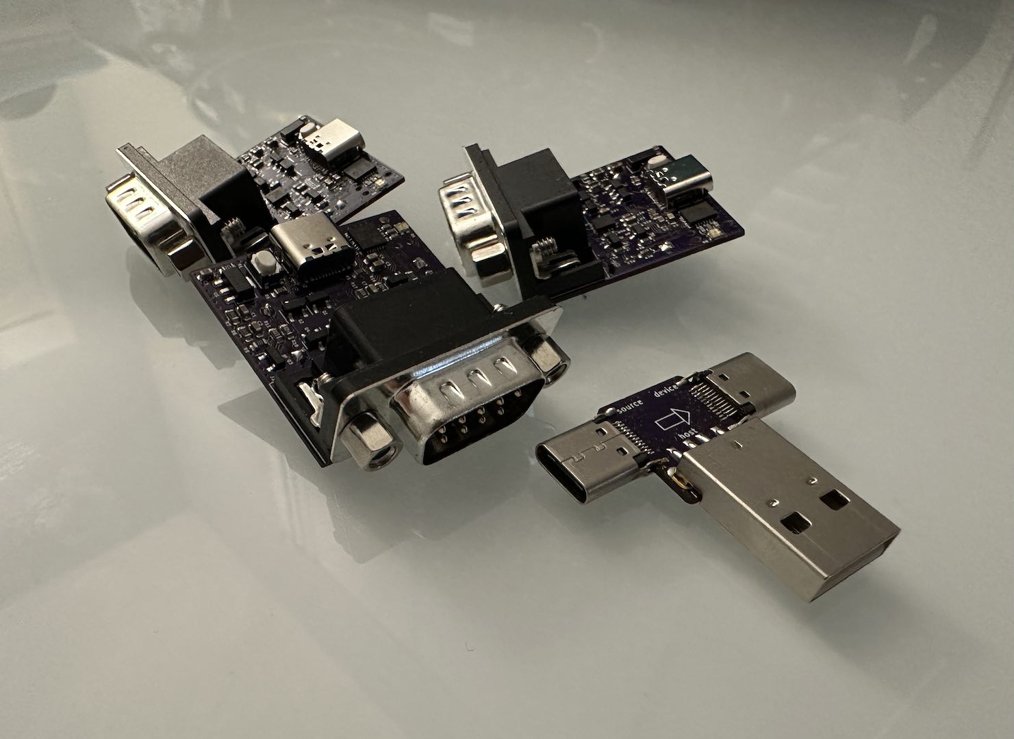
Matthew Tran's Blog!
Added core support for the CH32X035 along with USB FS, USB PD, ADC, and UART drivers. Supporting other CH32V parts will be relatively straightforward.
slender iron
Can you see the guide with https://learn.adafruit.com/implementers-guide-to-circuitpython-api/overview?preview_token=NXki5quOVZd7I7_ilEDxuw ?
stuck elbow
slender iron
Can you see the guide with <https://learn.adafruit.com/implementers-guide-to-cir...
yes, I have an account
thank you!
manic glacierBOT
Thanks for the thorough testing. I retested I2SOut on an RP2040 and and RP2040 Prop-Maker.
tulip sleet
@slender iron @onyx hinge Now that the PIO and IDF 5.3.2 PRs are merged, I think that's a good place to do 9.2.2. I will merge the Translation PR that is currently running and then make a release.
slender iron
want to do an RC to give 5.3.2 a little soak time?
tulip sleet
I could, but I think very few people will try it. I tested wifi and BLE, which I think would be most likely subject to regression. I can do an rc until Monday if you think that would make sense.
we are not in a hurry, it's true
slender iron
meh, we can always do 9.2.3 if an issue comes up
tulip sleet
yah. I will be around to do any emergency fixes
manic glacierBOT
Confirmed this is fixed, but I have to reconnect to the USB device port after downloading (as per Retired Wizard's description, which is rather inconvenient, but necessary I suppose to get the the USB mass storage device to show up.
manic glacierBOT
mortal kernel
slender iron
You still need the binding for the Python -> C layer. shared-module is for the i...
Thanks, I think I've got it. Python bindings go in shared-bindings and the module's implementation (if any) goes in shared-module. Some implementation bits like protocol methods (ex., standard stream methods) go into shared-bindings, so there's a bit of discretion involved.
manic glacierBOT
I'm skeptical about this, but I just put this artifact on a Solder Party 2350 Stamp XL in the RP2xxx carrier board and it's resulting in a boot straight to safe mode.
@RetiredWizard I tried artifacts from https://github.com/adafruit/circuitpython/actions/runs/12678008250 on my proto Metro RP2350 (RP2350B). The board UF2 works with no safe mode, and so does the Solder Party 2350 Stamp XL UF2. There is no interesting code.py.
Okay, well I'm getting the safe mode boot with stable as well so I'll do some more digging to see if it's just my board.
I deleted code.py/main.py just to be sure :grin:
Definitely something on my end, I just had good boots from 9.2.0, then 9.2.1 and now the firmware you linked is working fine. Sorry for the false alarm....
@RetiredWizard np - thank you for testing!
wraith crow
I think something may still be going on, but I'll wait until I have something more definitive and open an issue. Thanks!
onyx hinge
Thanks Dan!
manic glacierBOT
I believe this is the crash I was running into this afternoon. In my case changing the color_depth parameter to 4 avoided the crash but then framebufferio complains about the 320,240 resolution.
[adafruit/circuitpython] New tag created: 9.2.2
orchid basinBOT

Automated website update for release 9.2.2 by Blinka.
New boards:
- 8086_rp2040_interfacer
- apard32690
- heiafr_picomo_v3
- heltec_wireless_paper
- m5stack_stick_c_plus2
- max32690evkit
- mtm_computer
- pimoroni_pico_plus2w
- pimoroni_plasma2350w
- sunton_esp32_2432S024C
- waveshare_esp32_s3_eth
- waveshare_esp32_s3_matrix
- waveshare_rp2350_geek
- waveshare_rp2350_lcd_0_96
- waveshare_rp2350_lcd_1_28
- waveshare_rp2350_one
- waveshare_rp2350_plus
- waveshare_rp2350_tiny
- waveshare_rp2350_...
tulip sleet
https://blog.adafruit.com/2025/01/09/circuitpython-9-2-2-released/
HIghlights of this release:
int.from_bytes()and.to_bytes()calls can omitbyteorderarg, as in CPython.DemuxKeyMatrix: add scan delay, addcolumns_to_anodesandtransposeargs.- Implement
audiomixer.MixerVoice.levelassynthio.BlockInput. displayionow supports 24-bit color depth.- Add
sideset_pindirstorp2pio.StateMachine. rp2pio: support on GPIO pins 32 and up, available on RP2350B.- Initial implementation of
audiobusio.PDMInon Espressif. - Update Espressif ESP-IDF to v5.3.2, which supports ESP32-P4 v1.0 chips.
- New
ports/analogport, initially supporting Analog Devices ADI MAX32690 microcontroller. - Over 20 new boards.
tulip sleet
 bitter dew
has anyone used PyCharm with CircuitPython and Raspberry Pi Pico/Pico2 ?
bitter dew
has anyone used PyCharm with CircuitPython and Raspberry Pi Pico/Pico2 ?
There's some discussion here: https://learn.adafruit.com/welcome-to-circuitpython/pycharm-and-circuitpython. It was written a while ago.
tulip sleet
#help-with-circuitpython is better for this
bitter dew
I'll try and ask there, thank you
tulip sleet
Please don't cross-post. Let's move discussion to there.
bitter dew
of course....I haven't cross-posted...I've read that this channel was a better place to ask for development. That's wehy I've asked here first
tulip sleet
I just saw your "Hello all", sorry. This is for development of CircuitPython, rather than in.
bitter dew
ah I see
ionic elk
I'm hopefully close to wrapping up my microros PR. I haven't submitted a PR in a while so I wanted to refresh on some protocol stuff:
- are draft PRs still best for stuff that's not quite ready yet?
- is the best place to ask around for compilation problems here, in the issue, or on the PR itself?
tulip sleet
ionic elk
I'm hopefully close to wrapping up my microros PR. I haven't submitted a PR in a...
yah sure on drafts. If you do a PR, we can look at the build problems easily in the PR build or clone it to build locally
ionic elk
I also have some style questions, structural stuff. MicroROS is a big component (lots of includes), has onerous build requirements (ROS Colcon) so I've precompiled it, and will probably not be used by many people (best kept optional?). Should I ask those in more detail here, in the issue, or on the PR?
tulip sleet
what chip family is this for? You know that Scott is working on zephyr, right?
ionic elk
this is for espressif. It's an existing component implementing microros
I'm not up to date on Scott's zephyr work but I'm not sure if there would be incompatibility, since microros in esp-idf projects is implemented within freertos
it's just kind of a proof of concept anyway
tulip sleet
well, if CIRCUITPY_MICROROS = 0 for most or all boards, then would it affect the normal builds? ... I was just mentioning zephyr in case you were looking for some general rtos stuff that might be covered by it. I don't really know what's in ROS.
I think I made an incorrect assumption about it.
ionic elk
yeah "robot operating system" is kind of a misnomer it's basically middleware for robotics programs, and MicroROS is just a DDS system that pipes data up to an agent on a more sophisticated platform in the right format
I'm just hoping to let circuitpython boards talk directly to ros platforms over Wifi so people can send commands to drone swarms or get sensor data or stuff like that
tulip sleet
never mind that - misunderstanding
ionic elk
don't go down the ROS rabbithole hahaha
I'm partially doing this project to learn about it so I may bang my head on it up to some point and then realize somethings horribly incompatible, who knows
tulip sleet
you can turn on CI builds in your own fork if you want, if you want to wait before presenting it to us 🙂
ionic elk
I'd be happy to get it up for comments now. Writing some background on it in the PR
I haven't done any API design work yet, I want to make sure it just compiles OK and we've determined whether it will play nice with the WIFI
Are there any boards where we compile more than one version per board? I feel like this could either be optional, or an "alternative" build for platforms like the M5Cardputer, which would be a good host for MicroROS
tulip sleet
CPX has multiple builds, as an example
tulip sleet
circuit playground express
atmel-samd
there is a build with displayio and one without because we had to shoehorn it in
it's done as multiple boards
ionic elk
ah ok, figured that might be how to do it
stuck elbow
ionic elk
yeah "robot operating system" is kind of a misnomer it's basically middleware fo...
I wonder of it would make more sense to just reimplement the protocol in python?
manic glacierBOT

This is very minor and only has one typo fix so it's low priority.
I did start to try to look into figuring out if the RP2350 also lacked the calibration function, but the honest issue I ran into was an absence of a reason why any of the chipsets lacked or had rtc calibration options in the first place.
So if this should be updated to include the RP2350 let me know!
ionic elk
stuck elbow
I wonder of it would make more sense to just reimplement the protocol in python?
possible but slower, and it would take a lot of disk space to store all the message formats ROS uses
orchid basinBOT

updating feather rp2350 with full product copy and shop image
manic glacierBOT
I tried this boot.py on an RP2040, with 40-character names.
import usb_midi

usb_midi.set_names(
    streaming_interface_name="SI-4567890123456789012345678901234567890",
    audio_control_interface_name="AC-4567890123456789012345678901234567890",
    in_jack_name="IJ-4567890123456789012345678901234567890",
    out_jack_name="OJ-4567890123456789012345678901234567890",
)
It works on Linux and macOS. On Windows 11 it does not work, as described above , if `audio_control_inte...
stuck elbow
ionic elk
possible but slower, and it would take a lot of disk space to store all the mess...
it doesn't necessarily have to be slower, and can't you just pick the one format that you need?
ionic elk
stuck elbow
it doesn't necessarily have to be slower, and can't you just pick the one format...
my more ROS-knowledgeable buddy and I evaluated both options a while ago and decided MicroROS's implementation of xrce-DDS sounded easier than python-implemented DDS messaging but I'd have to go back and find my notes for specifics
stuck elbow
ionic elk
my more ROS-knowledgeable buddy and I evaluated both options a while ago and dec...
yeah, sorry, I had several attempts at ros but bounced off each time, so I only know generals
ionic elk
The compute half is extremely annoying haha. But it's super common in both robotics companies and research labs which is why I wanted to have a crack at this
stuck elbow
but how complicated an event propagation system can be? ;-)
manic glacierBOT

This took so many hours to pin (hehe) down :sweat_smile:
manic glacierBOT
thank you, glad you tracked it down.
Fixes #9871.
usb_midi.set_names() prevents the MIDI device from being recognized if audio_control_interface_name is 32 chars or more. We can't check for this because we can't find out the host OS, but it's now documented.
I also prevented the doc build from looking inside things in ports/analog it shouldn't bother to look in.
manic glacierBOT
this frequently vexes me. perhaps we should explicitly list the documents we want with include_patterns instead (https://www.sphinx-doc.org/en/master/usage/configuration.html#confval-include_patterns)
manic glacierBOT
It frequently arises that files were inadvertently included in the doc build, because it was based on a series of exclude patterns, but new filenames that don't match the exclude patterns are frequently created by new build systems, new submodules, un-tidy developer source trees, etc.
So, use include_patterns as a set of positive patterns, then weed out a few specific items that otherwise match the include patterns.
This also fixes a diagnostic printed by setuptools_scm during `make stu...
jaunty juniper
anyone uses a Waveshare ESP32-S3 Pico ? The status LED on mine doesn't have the same color order as default so green status is red and red status is green (on UF2 too), I don't know if it's all of them or there are variants, so I don't want to change the board definition without checking
then again the only boards that use MICROPY_HW_NEOPIXEL_ORDER_GRB are waveshare boards, so maybe it's what they do
manic glacierBOT
The stubs build failed in the docs build :frowning_face: . I'll stop the rest of the jobs.
jaunty juniper
ah it's switched in their Micropython example so I'm gonna PR the change on both repos
by the way that board has a weird feature with a USB hub chip on board connecting on both the S3 USB pins and a serial chip connected to the default serial for programming (instead of having 2 USB ports like some boads do). But that USB hub chip is not recognized on my mac if connected to a hub instead of directly to the computer's port which raises so many questions on standards and drivers
kind of cool feature for developing when it works though I guess
manic glacierBOT
serves me right for messing with two things.
Updated to just include the include-list change.
the configuration that tried to use setuptools_scm was broken. Instead, provides circuitpython-stubs' setup.py with the version determined by setuptools_scm running in the git source directory.
Compared to the version originally in #9947 this adds fetching tags during the doc build.
Remember to also check if this worked on RTD!
crimson ferry
jaunty juniper
anyone uses a Waveshare ESP32-S3 Pico ? The status LED on mine doesn't have the ...
oddly, the Waveshare ESP32-S3-ETH uses RGB, even though a bunch of their other boards show as GRB in their wiki
jaunty juniper
yeah it seems it's only some of their boards 🤷
jaunty juniper
am I misunderstanding the naming logic or should MICROPY_HW_NEOPIXEL_ORDER_GRB be called RGB, since the order the bytes are sent by default is G then R then B, but R and G get swapped (to RGB) when the define is set ?
manic glacierBOT
I didn't find a clear documentation of the color order of the neopixel on the board, but the Micropython demo from Waveshare does swap red and green instead of the default (1, 0, 2, 3), so I think it's good.
# Set the color order for the NeoPixel object
rgb_led.ORDER = (0, 1, 2, 3)
Tested and the color is now correct (exceptions blink red instead of green).
manic glacierBOT

Add code modified from M5Stack Cardputer to allow direct support for the M5StampS3 board
https://shop.m5stack.com/products/m5stamp-esp32s3-module
Code for TFT LCD left intact but commented out, as board is sold with LCD in a variant set
https://shop.m5stack.com/products/cardputer-accessory-kit
 remote light
If anyone is able to check my addition of the M5Stamp S3 to the CircuitPython site that would be very helpful.
I can't get the local preview working on Windows.
I've also added a code block to add the optional LCD accessory, but I'm not sure that belongs on the download page.
https://github.com/StellasFun/circuitpython-org/tree/M5Stack-StampS3

GitHub
CircuitPython's website. Contribute to StellasFun/circuitpython-org development by creating an account on GitHub.
 strange ravine
moving my issue here
so im trying to build circuitpython for my STM32H7 board, and ive succesfully built it and flashed it, however, it doesnt werk
below are the build files i used, which are based off the nucleo H743 and the OpenMV H7 modified to fit my board
the board itself does work so its likely an issue with the firmware
below are the files im using for the build, i made them based on the nucleo h7 and openmv h7
pins.c was made using parse_pins_csv.py provided in the stm/tools folder, using a pins.csv from a board with nearly identical pinout to my board
orchid basinBOT
manic glacierBOT
strange ravine
Update, im getting somewhere

 frail widget
Hey CircuitPy fam. I'm new to the community and don't know the protocol so feel free to point me in the right direction. Here's my PR against the typing library: https://github.com/adafruit/Adafruit_CircuitPython_Typing/pull/46

GitHub
Hey CircuitPython typing team,
I found myself wanting type hinting for NVM access as described here: https://docs.circuitpython.org/en/latest/shared-bindings/nvm/index.html
I thought it might be us...
manic glacierBOT

CircuitPython version
Unable to access, but used adafruit-circuitpython-lilygo_tdisplay_s3-en_US-9.2.2.bin image.
Code/REPL
n/a
Behavior
Neither serial console nor ampy doesn't work on image adafruit-circuitpython-lilygo_tdisplay_s3-en_US-9.2.2.bin - repl is displayed on the screen, but serial on 115200 doesn't work.
Rollback to adafruit-circuitpython-lilygo_tdisplay_s3-en_US-9.2.1.bin image fix the problem.
Was able to consistently repro t...
manic glacierBOT

CircuitPython version
6.0.0
Code/REPL
import time
for i in range(1000000000):
    print(time.monotonic_ns())
    time.sleep(0.001)
Behavior
1431848724366
1431849700929
1431850677491
1431851654054
1431852630616
1431853607179
1431854583741
1431855560304
1431856536866
1431857513429
1431858520509
1431859466554
1432001098634 <-- wtf?
1432002044679
1432003021241
1432003997804
1432004974366
1432005981447
1432006927491
14320079...Im going to try to build an earlier version of circuitpython
strange ravine
i tried 9.2.1 but nah it didnt work
manic glacierBOT
CircuitPython is not a real-time system. Some interrupt or garbage-collection could have occurred that caused a delay. It could also be an old bug that was fixed. You said you are using 6.0.0, which is from 2020. Also please report what board you are using.
strange ravine
Its weird coz i got the flashing light after disabling the LSE
And i know the LSE and RTC works i tested it
manic glacierBOT
Noted as a result of https://forums.adafruit.com/viewtopic.php?t=215933
Adafruit CircuitPython 9.2.1-54-g26283dcb02 on 2025-01-06; Adafruit Metro ESP32S3 with ESP32S3
>>> import sdcardio,storage,board,os
>>> os.listdir()
['.fseventsd', '.metadata_never_index', '.Trashes', '.Trash-1000', 'sd', 'settings.toml', 'lib', 'boot_out.txt',  'ble_uart_echo_client.py']
>>> sdcard = sdcardio.SDCard(board.SPI(), board.SD_CS)
>>> vfs = storage.VfsFat(sdcard)
>>> storage.mount(vfs,"/sd")
>...This might be simpler to solve than the other VfsFat mount point issues, but just in case someone's digging around, I figured I'd link a couple possibly related issues #9045 and #8409
manic glacierBOT
Hi,
This is a Feather S2.
It appears to happen every second, the ~850000 to ~999999 are missing. It's extremely regular and there isn't a noticeable execution delay so doesn't appear to be a garbage collection phenomenon.
manic glacierBOT
Could you try 9.2.2 instead of 6.0.0?
jaunty juniper
hey, there has been many changes to adafruit_httpserver and adafruit_esp32spi since last time I used a board with that. I had a trick to make them work together by wrapping the ESP32SPI socket module with some compatibility layer, but it doesn't work anymore and it wasn't a quick fix.
by which I mean i can't seem to find how to fix it
manic glacierBOT
Though the extra listing is confusing, it does not seem to affect actual functionality.
tulip sleet
jaunty juniper
hey, there has been many changes to `adafruit_httpserver` and `adafruit_esp32spi...
I don't remember that this ever actually worked; if you had some trick, that would be great. There are issues: https://github.com/adafruit/Adafruit_CircuitPython_ESP32SPI/issues/203 and also multiple issues in the server library.
jaunty juniper
tulip sleet
I don't remember that this ever actually worked; if you had some trick, that wou...
testing on a Matrix Portal, my socket wrapper works with CP 8 and its version of the esp32spi library (before adafruit_esp32spi_socket became adafruit_esp32spi_socketpool), as well as adafruit_httpserver 4.0.0.
It implements missing functions as calls to the underlying interface when possible, or spoof thems if that works.
Updating everything to latest I get errors with setsockopt and constants like SOL_SOCKET not existing and other problems.
this is code that works on CP8 with httpserver 4.0.0:
tulip sleet
jaunty juniper
testing on a Matrix Portal, my socket wrapper works with CP 8 and its version of...
I don't know why it broke after esp32spi socketpool, but I think that could be tracked down. I think the compatibilities provided UniversalSocket incorporated into ESP32SPI would be a goal.
jaunty juniper
I almost get there by adding some of the missing things, but I would probably have to dive deep to make it work, I'll make that a goal for this year I think
reviving that Matrix Portal was an interesting experience, I found a bug in PNG imageload (filed an issue) and another with some BDF fonts that used to load correctly but now have a large empty space on the top
or that last one is an issue with display_text, not sure ?
jaunty juniper
ah the issue appear with bitmap_label and not label
oh yeah it's issue 214 over there, setting background_tight=True works as some temporary fix
manic glacierBOT
This draft PR is an attempt to add MicroROS as an optional addition to the Espressif port. The Robot Operating System (ROS and sucessor ROS2) is a very commonly used collection of software and standards in professional and research robotics. It is somewhat misnamed: it is not an operating system or RTOS, but a collection of middleware and type standards for different robot parts to talk to each other. MicroROS is an API for embedded systems that allows them to talk to a ROS system on a linux ...
lone sandalBOT

 arctic cliff
mimxrt10xx: NXP i.MX RT10xxx problem since CircuitPython 9.1.0
Up to CircuitPython version 9.0.5, a Metro M7 1011 delivered:
import microcontroller
dir(microcontroller.pin)
['class', 'GPIO_00', 'GPIO_01', 'GPIO_02', 'GPIO_03', 'GPIO_04', 'GPIO_05', 'GPIO_06', 'GPIO_07', 'GPIO_08', 'GPIO_09', 'GPIO_10', 'GPIO_11', 'GPIO_12', 'GPIO_13', 'GPIO_AD_00', 'GPIO_AD_01', 'GPIO_AD_02', 'GPIO_AD_03', 'GPIO_AD_04', 'GPIO_AD_05', 'GPIO_AD_06', 'GPIO_AD_07', 'GPIO_AD_08', 'GPIO_AD_09', 'GPIO_AD_10', 'GPIO_AD_11', 'GPIO_AD_12', 'GPIO_AD_13', 'GPIO_AD_14', 'GPIO_SD_00', 'GPIO_SD_01', 'GPIO_SD_02', 'GPIO_SD_03', 'GPIO_SD_04', 'GPIO_SD_05', 'GPIO_SD_06', 'GPIO_SD_07', 'GPIO_SD_08', 'GPIO_SD_09', 'GPIO_SD_10', 'GPIO_SD_11', 'GPIO_SD_12', 'GPIO_SD_13', 'USB_OTG1_DN', 'USB_OTG1_DP', 'dict']
this output.
Since version 9.1.0, the relevant information is lost:
import microcontroller
dir(microcontroller.pin)
['class', 'dict'].
Ditto for the Teensy 4.1:
import microcontroller
dir(microcontroller.pin)
['class', 'GPIO_AD_B0_00', 'GPIO_AD_B0_01', 'GPIO_AD_B0_02', 'GPIO_AD_B0_03', .........., 'USB_OTG1_DN', 'USB_OTG1_DP', 'USB_OTG2_DN', 'USB_OTG2_DP', 'dict'].
CircuitPython version 9.1.0 only returns: ['class', 'dict']. This also applies to the newer versions up to and including version 9.2.2.
Any hints?
ionic elk
Any ideas what this is from?
build-m5stack_cardputer/genhdr/qstrdefs.generated.h: In function 'MP_COMPRESSED_ROM_TEXT':
../../supervisor/shared/translate/translate_impl.h:39:49: error: implicit declaration of function 'strcmp' [-Werror=implicit-function-declaration]
   39 |     #define TRANSLATION(english_id, number) if (strcmp(original, english_id) == 0) { return (mp_rom_error_text_t)&translation##number; } else
      |                                                 ^~~~~~
I don't really know how these translation generated files work, is it possible this is caused by a header file conflict or something?
tulip sleet
arctic cliff
mimxrt10xx: NXP i.MX RT10xxx problem since CircuitPython 9.1.0
Up to CircuitPyth...
Could you open an issue about this? https://github.com/adafruit/circuitpython/issues/choose Thanks.
tulip sleet
ionic elk
Any ideas what this is from?
```
build-m5stack_cardputer/genhdr/qstrdefs.generat...
did you do a make clean first?
ionic elk
make clean is actually not working for me?
- Verbosity options: any combination of "steps commands rules", as `make V=...` or env var BUILD_VERBOSE
../../py/mkrules.mk:172: target `build-/peripherals' given more than once in the same rule.
rm -rf build-
I get this and then it doesn't actually do rm -rf build-
do I need to run it from root
(Worth noting that I did do it manually)
jaunty juniper
shouldn' it be rm -rf build-* ?
ionic elk
seems like a very reasonable hypothesis
this is the mkrules bit
clean:
    $(RM) -rf $(BUILD) $(CLEAN_EXTRA)
.PHONY: clean
build-/peripherals kind of looks like a variable extrapolation error, which happened when using the mac's internal version of make, which was an issue with tinyuf2, but gmake still doesn't clean anything, just without the complaint
❯ gmake clean
- Verbosity options: any combination of "steps commands rules", as `make V=...` or env var BUILD_VERBOSE
rm -rf build-
did you specify a BOARD?
jaunty juniper
yeah I think it only supports cleaning a board, there's no clean all
or is there ?
stuck elbow
not that I know
stuck elbow
I mean I do "make clean all" but that's just doing "make clean" and then "make" but in one step
ionic elk
Maybe I can do a cheeky PR for a warning message there
stuck elbow
there should actually be an error when board is not specified
other makefiles do that
jaunty juniper
yeah, and you could implement clean-all: rm -rf build-* 😉
ionic elk
if someone else can validate it's actually missing and this isn't just me messing something up I'm happy to add that in
ok I can 100% verify my string issue happens immediately after an rm -rf build-*, validated that directory is gone, with no intermediate steps. Full error:
In file included from ../../supervisor/shared/translate/translate.h:26,
                 from ../../py/misc.h:332,
                 from ../../py/mpstate.h:33,
                 from ../../py/mpstate.c:27:
build-m5stack_cardputer/genhdr/qstrdefs.generated.h: In function 'MP_COMPRESSED_ROM_TEXT':
../../supervisor/shared/translate/translate_impl.h:39:49: error: implicit declaration of function 'strcmp' [-Werror=implicit-function-declaration]
   39 |     #define TRANSLATION(english_id, number) if (strcmp(original, english_id) == 0) { return (mp_rom_error_text_t)&translation##number; } else
      |                                                 ^~~~~~
build-m5stack_cardputer/genhdr/qstrdefs.generated.h:1938:1: note: in expansion of macro 'TRANSLATION'
 1938 | TRANSLATION("  File \"%q\", line %d", 0)
      | ^~~~~~~~~~~
In file included from ../../supervisor/shared/translate/translate_impl.h:19:
build-m5stack_cardputer/genhdr/qstrdefs.generated.h:1:1: note: include '<string.h>' or provide a declaration of 'strcmp'
  +++ |+#include <string.h>
    1 | // This file was automatically generated by makeqstrdata.py
cc1: all warnings being treated as errors
-e See https://learn.adafruit.com/building-circuitpython; Adafruit Discord #circuitpython-dev
make: *** [build-m5stack_cardputer/py/mpstate.o] Error 1
supervisor/shared/translate/translate.h explicitly includes <string.h> at line 11 in my copy, before including "translate_impl.h" on line 26. So, I dunno why you're seeing this.
is it possible you've created/added a file named string.h that is being erroneously included in lieu of the system header? otherwise, I don't have any top-of-head guesses.
ionic elk
yes it's possible, that's what I was hoping to find out, is whether that was the likely cause
I'll see if I can dig out that file and exclude it somehow
onyx hinge
If I create the file ports/espressif/string.h with the content this ruins everything it does in fact ruin everything. This is because the current directory is listed as -I. in the Makefile INC variable, meaning that it is consulted for <headers> and "headers". -isystem is the same. -iquote only adds it for "header" searches, not all searches. So you could try changing the problematic inclusion path to use -iquote instead of -I or -isystem
https://gcc.gnu.org/onlinedocs/gcc/Directory-Options.html there's also -idirafter which can add the directory to the END of the include path instead of the start, according to the docs. I'm not familiar with it.
Directory Options (Using the GNU Compiler Collection (GCC))
ionic elk
ok, I'll give that a shot!
and that's a good start for me to do my own research and learn more about these options
onyx hinge
you can also generate the preprocessed source for any file so you can inspect it: $ make BOARD=adafruit_metro_esp32s2 build-adafruit_metro_esp32s2/py/mpstate.pp creates build-adafruit_metro_esp32s2/py/mpstate.pp with about 48k lines in it
ionic elk
I'm going to cross my fingers here and hope for the best but if this problem just moves to other headers causing similar issues I may have to re-evaluate my strategy
MicroROS comes with a huge collection of headers
yeah sadly it's just moving on to new errors. I'll have to research how to try and cordone off header conflicts in a bulk way
../../supervisor/shared/web_workflow/web_workflow.c:1163:13: error: implicit declaration of function 'strcasecmp'
https://github.com/micro-ROS/micro_ros_arduino/blob/4d6ed1f902eaf3eb4eefe660ecac32639a963c69/src/rcl/publisher.h#L84 totally in guessing territory here, but if it's part of std_msgs I think the directory that should be listed in the compiler flags is the one containing std_msgs because the inclusion is written as #include <std_msgs/msg/string.h> here.
ionic elk
find shows these inclusions of string.h
./microros-ext/include/example_interfaces/example_interfaces/msg/string.h
./microros-ext/include/std_msgs/std_msgs/msg/string.h
./microros-ext/include/rosidl_runtime_c/rosidl_runtime_c/string.h
./esp-idf/components/linux/linux_include/string.h
i tried replacing those paths from isystem to iquote which fixed the first issue but resulted in the second. But I'm just cargo culting rn and have to learn up on what iquote actually does
onyx hinge
yeah that one is included inside one of their source files as #include "rosidl_runtime_c/string.h" so the inclusion directive (whether -iquote or -I or whatever) should be something like -Imicroros-ext/include/rosidl_runtime_c (or -iquote), not -Imicroros-ext/include/rosidl_runtime_c/rosidl_runtime_c
ionic elk
ohh i see what you mean
Ok yes that could be causing it I was pretty crude about my include paths
onyx hinge
similarly ./microros-ext/include/std_msgs/std_msgs/msg/string.h maybe should be -Iext/include/std_msgs in the compiler flags + #include <std_msgs/msg/string.h> in the source file that needs it
they show that one <diamond> style so -iquote won't cut it
ionic elk
I'm pruning down all my includes and I'll see if that still flies, hopefully the style is consistent
onyx hinge
 ionic elk
yeah sorry for being kind of a chucklehead the OG project uses CMAKE and I don't know it very well
I don't think CMAKE has explicit includes lists at all right? So I just made it with find...
Probably a way to get it to spit out what I need for a makefile
onyx hinge
beats me, I don't know cmake well either
ionic elk
Random style question while I'm compiling - since the ROS includes directory is so bloated, should I move it to my own repo and link it in as a submodule? I don't want to attach the original microros component because building it requires ros-specific build tools like colcon and ament and I'd rather attach a prebuilt library per-target so the CI doesn't have to deal with that
onyx hinge
That's not a question I can answer. my gut is to use source code via submodules when it's feasible, but this is more of a tannewt judgement call I feel like
ionic elk
yeah that's why im iffy on it cuz this isn't actually source code, just a single .a file and then 400,000 lines of includes
IT BUILT
RAHHH
onyx hinge
fwiw https://github.com/adafruit/circuitpython/commit/5db6db01287079b0314a5356cd9b5c40886e4d23 incorporated something already properly set up as an esp-idf "component" into our build.
GitHub
This uses the esp32-camera code instead of our own homebrewed camera code.
In theory it supports esp32, esp32-s2 and esp32-s3, as long as they have
PSRAM.
This is very basic and doesn't su...
ionic elk
it's not the component part that's the issue it's the extra python packages it installs
onyx hinge
[heading into a video call, ttyl]
ionic elk
I'm not even sure that colcon will work at all if not on a specific ubuntu version
anyway thanks for your help!! you got me through it
onyx hinge
another question I'd raise is whether the "binary .a" approach ties us to a specific esp-idf version, i.e., the one that the .a file was built for. I don't know whether this is typically the case or not, but we would probably think twice before taking things that make it harder to update a core dependency like that.
ionic elk
Honestly I'd be fine with a case where CPY_MICROROS simply gets turned off if it's ever holding anything back, restricting it to only specific versions of Circuitpython
Given that my plan thus far is to only include it as an optional build-it-yourself flag and maybe an alternative build for a couple of feathers or the M5Cardputer
If it actually is cool/gets used the discussion could pick back up then
jaunty juniper
I see supervisor.runtime.serial_connected being always True (both on a samd51 and an ESP32S3 board) regardless of whether I'm connected to the board (with tio). Meanwhile usb_cdc.console.connected does correctly report when I'm connected or not.
Is that expected behavior for supervisor.runtime.serial_connected ?
manic glacierBOT
Thank you and sorry for returning so late!
rtc.RTC().datetime = ntp.datetime
This solved my problem!
Regarding C3: mind that I talk about the XIAO ESP32-C3 module, not adafruits QT module. They XIAOs C3 and adafruits C3 behave different. But with this solution, I can make them behave the same. Thanks again!
strange ravine
Ah
So it hasnt worked in a while apparently
I should probably make an issue on the H7 port no longer working
austere acorn
strange ravine
I should probably make an issue on the H7 port no longer working
There already is one https://github.com/adafruit/circuitpython/issues/5470
I've been working with stm32h7 ports, and might have a fix for it, i'll post it here in a few days
strange ravine
austere acorn
I've been working with stm32h7 ports, and might have a fix for it, i'll post it ...
Omg thanks
austere acorn
strange ravine
Omg thanks
It took a while to check my fix, since there are only 2 boards for the H7, and one of them isn't produced anymore, but I got my hands on an openmv camera now. I can ping and let you know if you want.
strange ravine
austere acorn
It took a while to check my fix, since there are only 2 boards for the H7, and o...
Oki
Feel free to ping me at any time, ill try out your fixes on my own H7 board. It seems very few boards still use the H7 like the arduinos portenta and giga, i guess its that way since its a high end and expensive MCU
jaunty juniper
oh it seems that supervisor.runtime.serial_connected is True whenever there's a display, whether the REPL is on the screen or not
tulip sleet
ionic elk
Random style question while I'm compiling - since the ROS includes directory is ...
Are those python tools or system-installed tools. If it's just pip3 installs, I think it's OK to install them. There could be a separate requirements-something.txt for them if you are worried. As Jeff mentioned, having a prebuilt .a is problematic in several respects.
Where do the ROS includes come from? Did you copy them from some existing repo, or are they in esp-idf as a submodule? It's fine to have a submodule.
manic glacierBOT

On my Adafruit Metro ESP32-S3 with 16 MB Flash 8 MB PSRAM, all versions after adafruit-circuitpython-adafruit_metro_esp32s3-en_US-20241206-main-PR9873-c41d452.uf2 (PR9873) fail to restart CIRCUITPY upon flashing the UF2 and performing a hard reset of the board. I know there was a discussion on Issue #9888, and the thought was that PR9889 had fixed the issue but not for the Metro ESP32-S3 board. Upon flashing the UF2, CIRCUITPY does reappear, but if you reset the board, the volume fail...
manic glacierBOT
Reposted from comment in #9889:
On my Adafruit Metro ESP32-S3 with 16 MB Flash 8 MB PSRAM, all versions **after** adafruit-circuitpython-adafruit_metro_esp32s3-en_US-20241206-main-PR9873-c41d452.uf2 (**#9873**) fail to restart CIRCUITPY upon flashing the UF2 and performing a hard reset of the board. I know there was a discussion on Issue #9888, and the thought was that PR9889 had fixed the issue but not for the Metro ESP32-S3 board. Upon flashing the UF2, CIRCUITPY does reap...
I am unable to duplicate this on my own Metro ESP32-S3. Could you try a clean install from here: https://circuitpython.org/board/adafruit_metro_esp32s3/ ? Copy off anything in CIRCUITPY you need to save. Then hold the BOOT button and press the RESET button. Let go of BOOT, and press the "OPEN INSTALLER" button on that page. Let it erase the flash. You will need to reset the board twice, once when it asks you to select the METROS3BOOT drive, and once when it asks you to select the CIRCUITPY dr...
manic glacierBOT
Thanks. I wiped the Metro ESP32-S3 (after putting it into METROS3BOOT, which does appear) using metro-esp32-s3-factory-reset.UF2. I also tried applying metro-esp32-s3-factory-reset.bin using the Adafruit ESPTool and also tried applying combined.bin from tinyuf2-adafruit_metro_esp32s3-0.20.1.zip - all with the same effect. adafruit-circuitpython-adafruit_metro_esp32s3-en_US-9.2.1.uf2 works fine after a cold MCU boot (CIRCUITPY appears) while applying adafruit-circuitpython-adafruit_metro_esp32...
I should add there is a small B by pin #5085
I bought this from Adafruit on November 10, 2023 and attached is the output from ESPTool before flashing.
manic glacierBOT
For completeness, the same issue occurs in my Adafruit ESP32-S3 Feather with 4MB Flash 2MB PSRAM (Part ID 5477) that I purchased from Adafruit on 5/12/2024. Flashing adafruit-circuitpython-adafruit_feather_esp32s3_4mbflash_2mbpsram-en_US-20241202-main-PR9840-617915e.uf2 works (CIRCUITPY appears after a cold boot) but the next PR for adafruit-circuitpython-adafruit_feather_esp32s3_4mbflash_2mbpsram-en_US-20241206-main-PR9841-5c09b90.uf2 fails to load CIRCUITPY upon reboot. I don't ...
Thanks for your detailed report. I have the same vintage Metro, with exactly the same ID numbers on the can. I also have the same esptool output. We saw a similar report of an issue with a Feather 4/2 as well. The user in that case had a newer rev board. There's a long thread starting here: #help-with-circuitpython message
What is your host computer, and what is the OS and version on it? If it's a PC, could you give the brand and model ...
Aha! I have reproduced the problem when plugging directly into a USB2 or USB3 port. Previously I was using a hub.
Via some bisection, I narrowed it down to a change between 2024-12-06T15:00:13.000Z adafruit-circuitpython-adafruit_feather_esp32s3_4mbflash_2mbpsram-en_US-20241206-main-PR9873-c41d452.uf2 (which works) and 2024-12-06T19:44:29.000Z adafruit-circuitpython-adafruit_feather_esp32s3_4mbflash_2mbpsram-en_US-20241206-main-PR9841-5c09b90.uf2 (which does not work)
This will be a high priority for me to look at tomorrow. It's getting late here. Thanks!
Metro ESP32-S2 9.2.2 is OK with or without hub.
manic glacierBOT
This is probably a duplicate of #9956.
 lilac scaffold
austere acorn
It took a while to check my fix, since there are only 2 boards for the H7, and o...
lilac scaffold
austere acorn
It took a while to check my fix, since there are only 2 boards for the H7, and o...
Please please tag me if you figure it out
 tiny peak
tannewt, you asked for suggestions on well supported Zephyr boards... I've been having pretty good luck trying out various samples on a QT Py ESP32-S3 8flash/nopsram. For example, this works for BLE NUS UART:
west build -p always -b adafruit_qt_py_esp32s3/esp32s3/procpu --sysbuild samples/bluetooth/peripheral_nus
west flash
west espressif monitor
I can talk to it with the BluefruitConnect app from iPhone. Only catch is that the app needs to be ready and scanning before you run west espressif monitor (which resets the board, triggering the BLE advertisement at the start of the sample's main())
source for the sample, showing how they use the Zephyr bluetooth APIs is at https://github.com/zephyrproject-rtos/zephyr/blob/main/samples/bluetooth/peripheral_nus/src/main.c
Zephyr API docs for NUS are at https://docs.zephyrproject.org/apidoc/latest/nus_8h.html
there's also this "nus-console" snippet thing, whose readme claims it can be used to redirect Zephyr's console output to a BLE NUS UART:
https://github.com/zephyrproject-rtos/zephyr/tree/main/snippets/nus-console
manic glacierBOT

CircuitPython version
Adafruit CircuitPython 9.1.0 on 2024-07-10; Metro MIMXRT1011 with IMXRT1011DAE5A
Board ID:metro_m7_1011 and
Adafruit CircuitPython 9.1.0 on 2024-07-10; Teensy 4.1 with IMXRT1062DVJ6A
Board ID:teensy41
Code/REPL
>>> import microcontroller
>>> dir(microcontroller.pin)
Behavior
With CircuitPython 9.1.0 returns only: ['class', 'dict'].
With CircuitPython 9.0.5 returns: ['class', 'GPIO_00', 'GPIO_01', 'GPIO_02', '...
arctic cliff
tulip sleet
Could you open an issue about this? <https://github.com/adafruit/circuitpython/i...
Done! THX for the link.
strange ravine
I hope that by fixing the H7 port we can add support for more boards like the one by weact studios and then add support for the arduinos portenta, nicla and giga


 spare jacinth
i have the one of the left, it's been forgotten on a drawer for a few months, i could try and help with the porting work 🙂
my idea with it was to try out the LTDC peripheral, but it doesn't have external RAM, and the internal one is not big enough for the display i bought 🤣
slender iron
tiny peak
tannewt, you asked for suggestions on well supported Zephyr boards... I've been ...
nice! I'm excited to implement ble in the zephyr port
slender iron
strange ravine
I hope that by fixing the H7 port we can add support for more boards like the on...
My plan is to put more work in to the zephyr port and hope that the stm32 stuff comes with it
strange ravine
slender iron
My plan is to put more work in to the zephyr port and hope that the stm32 stuff ...
 manic glacierBOT
Confirmed that this is due to #9841.
lone axle
<@&356864093652516868> the weeking meeting will occur here on discord in just a bit over one hour from now at the usual time of 2pm US eastern / 11am US Pacific. You can add your notes to the document ahead of time if you like here: https://docs.google.com/document/d/1zy3Dm9Hb6pBi3phJY4S6hOdAvgtOnlOcx-dCMBeFvbo/edit?usp=sharing We look forward to hearing from everyone.

Google Docs
CircuitPython Weekly Meeting for January 13th, 2025 Welcome to the CircuitPython Weekly meeting notes! Feel free to add your Hug Reports and Status Updates before the meeting, alphabetically by your username. During the meeting, we go through them in order. If you can’t make the meeting and woul...
manic glacierBOT
Current Pico-PIO-USB says:
- 1 PIO, 3 state machines, 32 instructions
but we check for 2 PIOs with 31+22 instructions:
    if (!_has_program_room(pio_cfg.pio_tx_num, 22) || tx_sm_free < 1 ||
        !(tx_sm_free == 4 || is_gpio_compatible(pio_tx, used_gpio_ranges)) ||
        !_has_program_room(pio_cfg.pio_rx_num, 31) || rx_sm_free < 2 ||
        !(rx_sm_free == 4 || is_gpio_compatible(pio_rx, used_gpio_ranges))) {
mp_raise_RuntimeError(MP_ERROR_TEXT("All state m...PR added for List option for circup. @lone axle https://github.com/adafruit/circup/pull/240
GitHub
This PR adds the --list and --rename options to the circup example command.
Example now includes an option --list which will allow searching for examples.
Examples are:
circup example --list reques...