#microcontrollers
1 messages · Page 24 of 1
 waxen scroll
C is good for microcontrollers
 pastel solar
Oh okay
waxen scroll
C is good for fast io stuff on microcontrollers, but python is good for data processing/visualization
 gritty canyon
not exactly a python related question, but is renesas edge computing system fast compared to other embedded systems?
 compact cliff
With the Pico you can go circuit-python and the tutorials on adafruit are excellent
 oblique kettle
when u start id even recommend buying smth like an esp32 or 8266, they can be coded pretty much the same as an arduino but add wifi and or bluetooth capabilities
 errant wigeon
Yeah the structure I'd use is having one host a site with a page that accepts a POST input, the having the other 10 post packets to the first.
 fluid flower
definitely the pycom board, theres no code on windows yet, i was attempting to use a BLE tool called "Bluetooth LE Lab"
errant wigeon
https://www.adafruit.com/product/3333 This is a good starter microcontroller board with lots of peripherals and it can run circuit python if that's what you're after

Circuit Playground Express is the next step towards a perfect introduction to electronics and programming. We've taken the original Circuit Playground Classic and made it even better! ...
fluid flower
a raspi is like, twice the price though
pastel solar
the pico
fluid flower
oh hu
errant wigeon
pastel solar
Thats pretty expensive
It does come with a lot built in, whereas the pico is more or less just the micro and pins. I've you've got a ton of other stuff laying around, like LEDs, buzzers, ir transmitters receivers, etc, then the pico is a good choice. But the circuit playground has a ton built in so you don't have to worry about wiring things together when you're first learning about micros
errant wigeon
fluid flower
definitely the pycom board, theres no code on windows yet, i was attempting to u...
Ok, that should give me something to look for. Adafruit has been looking to add BLE based programming support to some of their boards, but I think they're building their own stack for it (I could be wrong) so I don't know how much cross over there is between circuit python's BLE stack and micro python's BLE stack
fluid flower
errant wigeon
Ok, that should give me something to look for. Adafruit has been looking to add...
thank you, im just surprised anyone here has even a hint of a idea. judging by the forum threads, most of which are full with people asking for help and devoid of any answers, thats rare.
errant wigeon
Yeah I've been trying to pair my wii balance board with a raspberry pi to act as a smart scale at home, and actually bonding to the pi has been my pain point with it.
pastel solar
wait, what can i really do with a micro-controller?
errant wigeon
You might actually have good luck on the adafruit channel since the core devs are really focused on the ble workflow right now too
fluid flower
idk, pycom is not really adafruit is it?
errant wigeon
pastel solar
wait, what can i really do with a micro-controller?
A lot, blinking an LED sounds simple but I will never grow tired of that one. I've got a micro collecting air quality data and saving it to my home server, another one is going to track my sleep to help see if I'm getting enough sleep, and to adjust my alarm clocks time it goes off, you can make robots or fun LED animations, etc
fluid flower
pastel solar
wait, what can i really do with a micro-controller?
something as plain as the pico? do anything with what you can hook up to it and get signals from or send signals to. its pretty dependant on the stuff you hook up to it because it has nothing built in. theres other boards with IoT networking etc built in, which open ups more possibilities (thats what im chatting with Keith about, a board that has bluetooth support)
pastel solar
Can i like code robots?
fluid flower
yep, but you'll need a motor driver
most microcontrollers dont have enough power for driving motors
pastel solar
what is a motor driver?
fluid flower
its a board which powers the motors based on what the microcontroller tells it to do
errant wigeon
fluid flower
idk, pycom is not really adafruit is it?
You're right, and that might mean they can't really help you since they can't offer support, but since they're working with bluetooth right now they might be able to point you in a useful direction. I'll be googling a solution for you as well and if I get any success with it I'll let you know. I'm just guessing that you're probably facing bonding issue with these devices because that's the issue I've been facing with my bluetooth project
pastel solar
fluid flower
its a board which powers the motors based on what the microcontroller tells it t...
oh, thats cool!
fluid flower
errant wigeon
You're right, and that might mean they can't really help you since they can't of...
yeah, it doesn't really help that im not really sure how BLE works on a higher level, so maybe you're right and i should ask there
errant wigeon
fluid flower
yeah, it doesn't really help that im not really sure how BLE works on a higher l...
Yeah, there's a bunch of different protocals, and different data pipes you need to initiate if you're doing one and not the other, etc. I think in two years the workflow will be a lot better, but until then it's a pain digging through ambiguous blogs from 2008, trying their c code, and then wondering exactly what part of the toolchain is broken in your build that wasn't in theirs
fluid flower
errant wigeon
Yeah, there's a bunch of different protocals, and different data pipes you need ...
trying C code is especially a pain if you dont have any way to actually run C code 
errant wigeon
Hunting for the c equivalent in python then lol. I've just hated bluetooth stuff lately. I'm getting a better handle on it, but I still haven't gotten the equivalent of a "blinking LED" moment yet
fluid flower
the annoying thing is that its not even the main thing i should work on. NB-IoT/CAT-M1 would be more important but im missing the SIM for that, and LoRA would also be interesting but im missing the antenna for that.
errant wigeon
fluid flower
the annoying thing is that its not even the main thing i should work on. NB-IoT/...
For the LORA, if you've got the fitting, a lot of folks have had great success with homemade antenna: https://hackaday.com/2018/03/31/build-your-own-antenna-for-outdoor-monitoring-with-lora/
fluid flower
errant wigeon
For the LORA, if you've got the fitting, a lot of folks have had great success w...
i dont, thats the main issue. some sort of antenna could be found but its that small connector on the board which i font have anything to using
fluid flower
errant wigeon
You might actually have good luck on the adafruit channel since the core devs ar...
could you send me a link to that?
errant wigeon
fluid flower
could you send me a link to that?
I think help with circuit python might be the best choice? I'll hop in and say I directed you there as well, I'm going through the micropython ble stuff on github that I linked earlier right now
fluid flower
errant wigeon
I think help with circuit python might be the best choice? I'll hop in and say I...
i was gonna ask in help-with-radio since its bluetooth related and im using micropython not circuitpython
errant wigeon
That makes sense--I'll hop in there then
pastel solar
i just bought a raspberry pi, and like do i NEED a motor driver to make robotics?
errant wigeon
The pico or a rasbperry pi 3 or something?
If you're going to drive motors, you should get a motor driver. Most devices don't have much protection on the gpio pins and motors spike the current and can fry the board. The driver board does two things: It lets you add more power to the motors themselves than you can get from a micro, and it protects the micro from the motors
so regardless of pico or a pi embedded linux device, you'll want a driver
pastel solar
the pico
 hallow igloo
Someone told me that shutting off and turning on your computer does more damage because of the fact that millions of electrons rush in and out of the components everytime you power up or shut down, and that they race and bump into each other, heating up all the parts. He recommended me to keep my devices on 24/7. Should I be leaving my stuff on for as long as possible? Not counting electricity costs but for the sake of maximizing the lifespan of my components.
 steep dune
correct - i would say it a different way , there is a spike of inrush currents on start up - this affects components - some old BBS systems are on 24/7 , 365 , because of this ... this is the way
errant wigeon
hallow igloo
Someone told me that shutting off and turning on your computer does more damage ...
I wouldn't worry about it. Some parts will get old, get hot, and fail when you power them on, and would have lasted a touch longer if you kept it running. But if you kept it running you could easily have worn them down faster. It's kind of a wash, there's enough power regulation on more expensive stuff that while there's an inrush on powerup, it's not usually fatal to the system.
hallow igloo
yall i bought a circuit playground express, its totally worth it
and you can program it using micropython
 pulsar sun
hallow igloo
Someone told me that shutting off and turning on your computer does more damage ...
pulsar sun
hallow igloo
Someone told me that shutting off and turning on your computer does more damage ...
millions of electrons run in and out of the components
did they ever take basic physics
if that's happening you have bigger things to worry about
such as the ridiculous amount of current through those circuits, the amount of heat they put out, and the resulting explosion
(by millions I presume they mean millions of times more)
hallow igloo
pulsar sun
> millions of electrons run in and out of the components
did they ever take basi...
"Thinks about what's happening when you turn a electric device the moment the circuit closes its releases millions of electrons racing and bumping and heating up all the parts" sic
hallow igloo
pulsar sun
> millions of electrons run in and out of the components
did they ever take basi...
Sorry that was just my wrong rephrasing
pulsar sun
the electrons stay in there right
I mean I feel like there's gonna be a lot of problems
 weak basin
pulsar sun
the electrons stay in there right
weak basin
pulsar sun
the electrons stay in there right
the electrons do move, but very slowly
pulsar sun
yes - I took physics in high school
about a metre per hour
but if you stop the potential difference they stay in there?
so all of those charges leaving the component would be very bad
guess it depends on how fast we're talking
fluid flower
its like a pipe filled with water, if you pump in more some will have to come out somewhere, the only differece is that this pipe doesn't really drain.
individual electrons are quite slow
 timber schooner
steep dune
correct - i would say it a different way , there is a spike of inrush currents o...
timber schooner
steep dune
correct - i would say it a different way , there is a spike of inrush currents o...
this happens only for inductive loads, typically: large motors, fluorescent lamps, and electronic circuits with inductors. Any good design will include a suitably-sized capacitor to absorb the spike before it can affect sensitive components.
errant wigeon
https://www.ti.com/lit/an/slva670a/slva670a.pdf?ts=1628770120746&ref_url=https%253A%252F%252Fwww.google.com%252F
This is a good application report on inrush current.
Most power circuits follow these principles for nicer electronics
timber schooner
uhm... interesting. I'm afraid my experience in electronics is a bit more... rustic
 errant wigeon
Ah but that's such a great bit of rustic electronics
pastel solar
I just got my Raspberry pi pico and I have no idea how to use it
errant wigeon
pastel solar
I just got my Raspberry pi pico and I have no idea how to use it
This should help you out: https://www.raspberrypi.org/documentation/rp2040/getting-started/
pastel solar
its not making a storage device called RPI-RP2
errant wigeon
What are you trying to do with it?
pastel solar
Im trying to connect it to my pc so i can code it
errant wigeon
Ok, what do you want to use with it, circuit python, micro python, or something else?
pastel solar
Micro python
errant wigeon
Ok cool. I don't think micro python shows up as a board once you get the bootloader on it
so that should be what you want if you followed the install instructions
 glacial turtle
Hi, i need help. i am trying to use the bmp280 pressure sensor with an esp8266 flashed wth micropython. I have made a code and added a library that i found online. When i try to upload the code i get this error messages: Traceback (most recent call last):
File "<stdin>", line 6, in <module>
File "/lib/bmp280.py", line 52, in init
OSError: [Errno 110] ETIMEDOUT Down here i will put the codes. Please help me!
this is my code:
 hasty zealotBOT
Hey @glacial turtle!
It looks like you tried to attach a Python file - please use a code-pasting service such as https://paste.pythondiscord.com
glacial turtle
from machine import I2C
from bmp280 import BMP280
import utime
import sys
bus = machine.I2C(sda=machine.Pin(4),scl=machine.Pin(5))
bmp = BMP280(bus)
file = open("datalog.txt", "w")
pin = machine.Pin(16)
start = utime.time()
def millis() -> int:
return int((utime.time() - start) * 1000)
while True:
print(bmp.temperature)
print(bmp.pressure)
print(millis())
file.write(bmp.temperature," ")
file.write(bmp.pressure, " ")
file.write(millis())
utime.sleep(0.2)
if pin.value() == 1:
file.close()
sys.exit()
and this is the library:
hasty zealotBOT
Hey @glacial turtle!
Uh-oh! It looks like your message got zapped by our spam filter. We currently don't allow .txt attachments, so here are some tips to help you travel safely:
• If you attempted to send a message longer than 2000 characters, try shortening your message to fit within the character limit or use a pasting service (see below)
• If you tried to show someone your code, you can use codeblocks
(run !code-blocks in #bot-commands for more information) or use a pasting service like:
errant wigeon
glacial turtle
from machine import I2C
from bmp280 import BMP280
import utime
import sys
bus = ...
Go ahead and post the code to the pastebin the discord bot suggested and I'll take a look at it
 vast pagoda
Not sure if this is the right spot to put this, but has anyone used Python to interface with a Raycus fiber laser?
errant wigeon
vast pagoda
Not sure if this is the right spot to put this, but has anyone used Python to in...
I never have, and that sounds like a specialized tool so there might not be many users here who have. But what kind of interfacing were you planning on using, and to do what?
pastel solar
bruh my raspberry pi pico just cant turn on
errant wigeon
What are you doing with the pico, have you held down the button to get the bootloader flashed onto it?
 grand crater
Does anyone know how to use an bmp280 with a micropython compatible board?
errant wigeon
grand crater
Does anyone know how to use an bmp280 with a micropython compatible board?
Give me a minute, I think that's the one I'm running, though I'm using circuit python
Cool, that is the one I use
I use the circuit python library for it, but I think the code should transfer
This is the code that handles the sensor: https://github.com/adafruit/Adafruit_CircuitPython_BME280/blob/main/adafruit_bme280/basic.py
And this is the root of the repo: https://github.com/adafruit/Adafruit_CircuitPython_BME280
Looks like this repo also uses the adafruit repo and ports it to micropython--that said the work to make it port is pretty minimal: https://github.com/robert-hh/BME280
This all assumes you're using i2c to interface with it I suppose
steep dune
i dont think a pico pi has wifi , right?
that would raise cost
im on my first coffee , looking to solve a freezer problem
-- i want to monitor a freezer , i want amessage sent via wifi to router ip there is a EVENT - that being power went off , temp dropped below set value , water on floor ... any other ideas????
-- is that the correct sensor from few days ago??
errant wigeon
steep dune
https://cdn-shop.adafruit.com/datasheets/BST-BMP280-DS001-11.pdf
Yeah that's the sensor.
You might just want to go straight to an esp device, the esp32-s2 has native usb support allowing it to easily run circuit python, some of the other esp's can run micro python
 white palm
I just found this Channel, all mircocontrollers i know are programmed in C, are there some that take python?
errant wigeon
white palm
I just found this Channel, all mircocontrollers i know are programmed in C, are ...
These can use circuit python: https://circuitpython.org/downloads
And these are some of what can use micropython: https://micropython.org/download/
errant wigeon
I think that might be the one that has space issues. I mean it's a micro so it's expected, but I've got a few of these https://www.adafruit.com/product/4775 and love that I can just mess around and not worry about space issues
STM32 is a great chip though
white palm
i am currently working on a Snaredrum that flashes when hit for a Friend of mine and i was planing to use a Adriuno nano, but from the looks of it i will try the Chip you send me.
steep dune
are you trying to record the percusssion curve of impact?
or just blink LED and call it a day
white palm
i want it to be reactive to the force of the impact
steep dune
will the curve data go to a drum systhethis thing
white palm
no that is not needed at the moment, but i want to have the option
steep dune
drum sensor( voltage out ) ---> ADC---> computer
white palm
pretty much and midi would be just convert it to a value between 0 and 255
would be needed for the LED anyways
steep dune
mmmm i dont know MIDI protocol - but im curious how to convert
hmmm how many drum pads
white palm
Midi is just a value for the note for example C1 for the deepest C and a velocity between 0 and 255
so it is just wich note and how loud
steep dune
did you ever look for a PDF explaining the data protocol
white palm
Have been a event technician for 5 Years my knowlege about midi stems from there, i have not read about it for a while now so i cant tell you too much about it
and i have not worked in that field for a few years now
you are really inquisitive, have you build something like that before?
 white palm
I hate your workspace - that is way to chaotic, and excuse my asking but what does the monster do
errant wigeon
steep dune
the monster
Is this Ben Eaters pc course?: https://www.youtube.com/watch?v=HyznrdDSSGM&list=PLowKtXNTBypGqImE405J2565dvjafglHU
steep dune
its a propeller 1 chip ( parallax.com ) , 8 cores , 32 GPIO , 2 custom counters per core -- i have it configured as a 8 bit data bus , 15 address lines , 3 bit chip address
my design - not others inferior designs
errant wigeon
steep dune
its a propeller 1 chip ( parallax.com ) , 8 cores , 32 GPIO , 2 custom counters ...
very nice!
white palm
errant wigeon
Is this Ben Eaters pc course?: https://www.youtube.com/watch?v=HyznrdDSSGM&list=...
white Noice -nice
oh my mac is just an idiot it has real sound
steep dune
128KB x 8 bit SRAM , RTC , 6x( 8 bit parallel ports ) , ADC( 8bit ) -- im using old junk chips from here and there -- Bens stuff is likely the latest greatest chips
the only really modern chip , is the propeller 1
errant wigeon
white palm
i am currently working on a Snaredrum that flashes when hit for a Friend of mine...
The board I linked is overkill, but it'll give you tons of room to play around with cool features. I like it as a, "This will feature creep" board
white palm
errant wigeon
The board I linked is overkill, but it'll give you tons of room to play around w...
It is cheap enough to just use it for that and test what it could do
a nano would be a better fit but who cares
steep dune
well - started with read switches - LED on off - then a driver to talk to a PIO - port chip ( read switch - LED display _ - then SRAM was the big deal
well i see the P1 chip as a swiss army knife -- i can create precision clocks , precise pulse widths
lotssss
errant wigeon
Once your build is done you can also swap out to a smaller chip and smaller form factor, but not having to worry about, "What if we add this" is awesome. Plus the esp32-s2 is growing on me and I'm starting to see uses for it everywhere
steep dune
well i wanted to make remote sensors - and a ESP32 has WIFI , some GPIO , but C bores me -- hoping Python3 or even uPython can be on it
white palm
errant wigeon
Once your build is done you can also swap out to a smaller chip and smaller form...
depending on the result we will outfit the whole kit with leds with the esp32-s2 we could control the complete set from one chip
steep dune
well - so many uC ( microcontrollers ) are out there and CPU( RasPi ) , so is good to be flexible
Python 3 ( PY3 ) , is super flexible , cross platform , and i can make GUIs with it
within PY3 is Tkinter , and to make a GUI is cooool , so i make virtual control panels
white palm
When i need to make a gui i use pysimpleguiqt - Tkinter does not play nice with me mac
or i am an Idiot and cant use it
steep dune
maybe i can make a few basic GUIs - then see if code is really cross platform
i use W10 and Ubuntu - so i try to have code play nice in both ENV ( environments )
white palm
The last thing i did worked fine on the windows laptop of my Gf but on my mac it had some issues
steep dune
can you explain........
steep dune
hmmm - i kinda know -- its a ... wont see variable untol clicked
no biggy
well from W10 its COM ports are seen as , ttyusb01 ( fuzzy memory ) on Linux
white palm
i have no problems with the lib i am using now so i have no incentive to switch
white palm
steep dune
well from W10 its COM ports are seen as , ttyusb01 ( fuzzy memory ) on Linux
okay, i have no idea what that means
steep dune
QT gui looks better - but .... i dont care im a wire poker , chip stroker , so Tkinter works
well in PY3 , a serial port is seen as COM , in Linux is seen as ttyusb01 , bla bla
the assumption is MAC sees it as ???
white palm
i have no idea, coding is just a hobby for me so my knowlege goes not that deep
hallow igloo
i want to build my own Firmware flasher for esp8266 but i don't know from where i should start
if anybody can guide me or share a link of any tutorial for building this, that would be awesome
 quick stump
hey guys has anybody tried connecting python programming to arduino through a library called pyfirmata? and has any body tried using the same python code in a raspberry pi to arduino connection?
errant wigeon
hallow igloo
i want to build my own Firmware flasher for esp8266 but i don't know from where ...
What parts do you have selected thus far? Are you using an uno to flash it or an ftdi cable, (https://www.monocilindro.com/2017/02/25/flashing-esp8266-using-ftdi-and-arduino-ide/) or are you using something else.
What kind of fimrware are you trying to flash to it, do you have it selected or are you writing your own?
errant wigeon
quick stump
hey guys has anybody tried connecting python programming to arduino through a li...
I've never used it, but I am confused by what you mean with the same code on a raspberry pi--I don't think it perfectly works on both. That said you can use pyserial to communicate between the two devices
quick stump
uh what i ment it
raspberry pi is basically a computer so when we connect python to arduino using pyfirmata we need a computer connected to the arduino.. the python program is put in the computer right? .. so instead of using a computer .. use a raspberry for the python code
errant wigeon
Ah, I see now. I misunderstood what it was suppose to be
Looking at the code structure, it should work on a pi as long as the arduino is programmed correctly too
 viral vault
Is it possible to set RPI Pico with e-paper display to change actual display (e.g. from chart of crypto price to to-do list) every x seconds/minutes or by pressing specific button near display?
hallow igloo
errant wigeon
What parts do you have selected thus far? Are you using an uno to flash it or an...
Dude, atleast read my question before asking those questions, You are one of those guys on stackoverflow who knows nothing but still replies to question with just anything,
I want to build my Own firmware flasher for esp8266, Flasher like the nodemcu flasher that flashes .bin files
errant wigeon
hallow igloo
Dude, atleast read my question before asking those questions, You are one of tho...
A lot of various skill levels use this form and I tend to start off the bat by finding some general guidance than seeing what applies and going from there. I don't know if you're after designing a full fpga structure to flash or if you just need an an ftdi cable, or if you're going design your own board and need the circuit to flash too. If you're after nodemcu or want your own files flashed. I know your target hardware and that's about it.
errant wigeon
viral vault
Is it possible to set RPI Pico with e-paper display to change actual display (e....
The pico should be able to drive the display change no problem, however for updating the price of things you'll need a way to talk to the pico since there's no built in wifi
viral vault
errant wigeon
The pico should be able to drive the display change no problem, however for upda...
I guess it's need to be sent using USB cable or if I want to use it completely independently switch to RPI Zero W
errant wigeon
viral vault
I guess it's need to be sent using USB cable or if I want to use it completely i...
Both options will work, the sent via usb isn't one I've used but I've got a pi 0w driving one screen, and have looked through some pico eink builds as well. They're both going to be fairly stable options
viral vault
So in the end there's no big difference between RPI 0W and Pico if the main goal of project is showing something on e-ink display?
errant wigeon
They are very different, but both are powerful enough to work in your setup. A pi0w is a full embedded linux device, so a lot of what you expect from any linux computer is running on a 0w. A pico on the other hand is a micro controller. It runs a bare metal version of python, or c depending on what you put on it. That runs your code and more or less only does what you tell your code to do.
viral vault
Then I think I'll go with RPI 0W since I need WiFi connection to connect with API to get data of crypto + connecting with SSH to edit to-do list which will be also displayed is pretty much needed feature
Thanks a lot
errant wigeon
Good luck!
viral vault
Thank you but dunno when I'll be able to do this project since I can't buy a RPI 0W due to shortage of them lol
errant wigeon
Are you able to get a pico and have it plugged into a computer?
viral vault
I guess so but cable needs to be at least 1,5m to set up pico on my desk
errant wigeon
Alternatively, if you're up for a little more advanced, you could get a pico and a module like an airlift to give it wifi abilities https://learn.adafruit.com/quickstart-rp2040-pico-with-wifi-and-circuitpython
viral vault
I'm definitely more familiar with Arduino Uno than RPI pico but why not, I can give it a try
errant wigeon
What kind of eink do you have?
so einks are going to require a boost converter, some have it built in
viral vault
I don't have one, I want to buy one to test, see how it works and use it
errant wigeon
Do you have a brand you're looking at? Waveshare makes one specifically for the pico
Adafruit also sells a section of eink screens (some with their own micro included) https://www.adafruit.com/category/150
viral vault
Not really but from what I see only Waveshare are available online
errant wigeon
And for a third alternative, there is good-display. I've never used them and I don't know how accessible their screens are. I've got a waveshare and an adafruit magtag
viral vault
I checked and only Waveshare is available so no big choice
errant wigeon
Given that, I'd try to make sure you get the pico ready one, just to minimize how much work you need to put into it
 versed python
hello everyone
i made a while ago a custom development board based on the PIC microcontroller
now i wanted to program it using custom commands..so i want to make some kind of compiler
maybe compiler is not the right word... it's better to say code converter😅
i want to create a program that scans those commands and convert them into something else... is it possible?
hallow igloo
I've been working on this Pi Alarm clock, and I'm using Pygame, and pygame.music.mixer to play audio, it runs fine when I manually ssh into the pi, and run it there, but when I try running it at boot, it doesn't work. Firstly, it seems like it waits until I've sshed into the pi to run the program, secondly, it has trouble opening the MP3 file for the alarm sound. I've tried editing rc.local, and .bashrc. Both don't work. I also tried booting the pi into a GUI rather than cmdline, didn't work. Is this just a pygame problem? Should I try a different lib for playing MP3 files?
If there is an alternative, it should be able to start, and stop, with code. Like pygame.music.mixer.stop() for example
hallow igloo
SimpleAudio doesn't work on Linux systems, like the Pi, and PlaySound wasn't working on my PC or the Pi, Pygame seemed to work best with most people playing audio on the Pi
It does say that MP3 support is limited in the Pygame docs, as of 2015, and it recommends OGG, so I will try that next.
hallow igloo
I tried OGG, didn't work, I also forgot to mention I tried adding a 10 second delay before the program calls the pygame.mixer function, didn't work either, I've seen MPG321, I'm still trying to find out if you can turn it off mid-song
 fair pasture
How can I use a C module with micropython?
This is on docs, but idk if it's right
and if I can use on a esp
or only on pyboard
grand crater
Hi, i am trying to use micropython with the esp8266 and use an bmp280, i have already installed micropython and it worked perfectly but when i try to use a library i have several errors, does anyone know any working library and how to use it?
errant wigeon
@grand crater See above: #microcontrollers message
 vocal ridge
Hello any advice on how to start as a newbie on microcontroller?
glacial turtle
Hi, I need help with something. I am trying to use the bmp280 sensor with an seeeduino xiao running circuitpthon 6x. My sensor is not adafruit orginal, it is one of the purple ones.
This is my code:
import board
import adafruit_bmp280
i2c = board.I2C()
sensor = adafruit_bmp280.Adafruit_BMP280_I2C(i2c)
And now i am getting this errors:
Traceback (ultima llamada reciente):
Archivo "<stdin>", l\u00ednea 4, en <module>
Archivo "adafruit_bmp280.py", l\u00ednea 442, en init
Archivo "adafruit_bus_device/i2c_device.py", l\u00ednea 50, en init
Archivo "adafruit_bus_device/i2c_device.py", l\u00ednea 166, en probe_for_device
Archivo "adafruit_bus_device/i2c_device.py", l\u00ednea 163, en probe_for_device
ValueError: No I2C device at address: 0x77
Some words are in spanish but i can translate them. Archivo=File, Linea=Line, en=in, "ultima llamada reciente"="last recent call"
What should i do to fix it?
 unborn totem
guys i wanna built a mini wheelchair prototype which i can control through raspberi pi ....can somebody tell me which dc motors should i use and what would i need for turning the wheels left and right (cos the dc motors only go forward and reverse)
 onyx mango
unborn totem
guys i wanna built a mini wheelchair prototype which i can control through raspb...
onyx mango
unborn totem
guys i wanna built a mini wheelchair prototype which i can control through raspb...
Maybe stepper motors to turn the wheels, or just steer by using different motor speeds on either wheel or driving in a different direction (kinda like a tank)
 pale sigil
How to start programing Arduino
viral vault
pale sigil
How to start programing Arduino
By buying one, plugging it into computer using attached USB cable, downloading and launching Arduino IDE
 soft dagger
pale sigil
How to start programing Arduino
soft dagger
pale sigil
How to start programing Arduino
Also I'm pretty sure Arduino uses more C than Python
 hushed gyro
Arduino is C++ from what I've heard
versed python
yeah arduino is C++.. currently there is no microcontroller programmable in python.. only micropython.. which is a python specific only for microcontrollers
 gentle vapor
Micropython is an implementation of python for microcontrollers, while some APIs are different, it's the same language
Circuitpython code in particular aims at being run as-is in C-python (on a raspberry pi for example), thanks to Blinka bringing the missing libraries to C-python
unborn totem
onyx mango
Maybe stepper motors to turn the wheels, or just steer by using different motor ...
ok thanks
 dry kindle
i dont know if i should ask this here but i am helping my friend build a machine that automatically cooks food for his science and engineering fair but i dont know circuit to use. he wants to be able to control motors and maybe make an user interface. any help would be appreciated
 hasty current
dry kindle
i dont know if i should ask this here but i am helping my friend build a machine...
hasty current
dry kindle
i dont know if i should ask this here but i am helping my friend build a machine...
Raspberry Pi
How sophisticated will the operation be?
dry kindle
he only gave me the rough drafts he said his 3d model lisence expired or something but i think that he needs the motors to operate a box to drop ingredients, a cutting knife, a nd a cooking pot
hasty current
What language will you be using for this?
Nvm dumb question.
I suggest a raspberry pi of some sort.
dry kindle
do i need a breadboard
hasty current
dry kindle
do i need a breadboard
?
dry kindle
i dont know what a breadboard does the only time i used it was to power some lights
will i need it to run motors
dry kindle
ok thanks for your help
hasty current
It's hella expensive for an engineering fair, tho.
dry kindle
75 dollars lol
hasty current
yup
for advanced operation of servo motors you will need a microcontroller which never comes cheap.
versed python
hasty current
for advanced operation of servo motors you will need a microcontroller which nev...
an stm32 board is like 5bucks
and is a very good microcontroller
 brazen meadow
dry kindle
i dont know if i should ask this here but i am helping my friend build a machine...
brazen meadow
dry kindle
i dont know if i should ask this here but i am helping my friend build a machine...
If you are going to use a Pi, a Pi Zero would probably be good enough. They are ~$20. Running a web app would allow you to use a phone, tablet or laptop wirelessly.
You could use an stm32 or esp32. A Pi would be a bit a easier with the user interface.
Servo motors would probably be the easiest way. These will cost a bit due to the forces at play.
You'll want to solder it up to make it robust. A breadboard will work early on.
There will be quite a bit of time needed to do it all.
versed python
brazen meadow
If you are going to use a Pi, a Pi Zero would probably be good enough. They are ...
a pi is easier than a microcontroller?? for real.. i though microprocessor are a bit trickier in comparison to microcontrollers
shouldn't you install the OS first?
brazen meadow
versed python
a pi is easier than a microcontroller?? for real.. i though microprocessor are a...
Controlling motors, servos, etc are the same difficulty on a Pi and micro.
User interface will probably be easier on a Pi, more options
versed python
brazen meadow
User interface will probably be easier on a Pi, more options
idk mam.. interfacing with a uC is also straightforward
brazen meadow
versed python
idk mam.. interfacing with a uC is also straightforward
Depends on what the interface is LCD + buttons, same difficulty on both. In this case I would use a micro.
 coral coyote
I would like to write a program on my pc to control the led strips attached to an arduino, which is connected with usb. How would I do that? Send every "frame" a string to the arduino per serial port which contains the colors for every stripe? Or do something else?
 flint hamlet
i want to use a raspberry pi to rotate a servo motor 90° every 24 hours this is the script i have so far:import RPi.GPIO as GPIO
import time
servoPIN = 17
GPIO.setmode(GPIO.BCM)
GPIO.setup(servoPIN, GPIO.OUT)
p = GPIO.PWM(servoPIN, 50) # GPIO 17 als PWM mit 50Hz
p.start(1.5) # Initialisierung
try:
while True:
p.ChangeDutyCycle(5)
time.sleep(0.5)
p.ChangeDutyCycle(7.5)
time.sleep(0.5)
p.ChangeDutyCycle(10)
time.sleep(0.5)
p.ChangeDutyCycle(12.5)
time.sleep(0.5)
p.ChangeDutyCycle(10)
time.sleep(0.5)
p.ChangeDutyCycle(7.5)
time.sleep(0.5)
p.ChangeDutyCycle(5)
time.sleep(0.5)
p.ChangeDutyCycle(2.5)
time.sleep(0.5)
except KeyboardInterrupt:
p.stop()
GPIO.cleanup()
can you help me with this?
because the script I found on the internet and can honestly no python so I am now looking for help
hallow igloo
you keep asking people who dont know about microcontrollers about help
 just wait for someone who knows about it
flint hamlet
okey
i want to use a raspberry pi to rotate a servo motor 90° every 24 hours this is the script i have so far:import RPi.GPIO as GPIO
import time
servoPIN = 17
GPIO.setmode(GPIO.BCM)
GPIO.setup(servoPIN, GPIO.OUT)
p = GPIO.PWM(servoPIN, 50) # GPIO 17 als PWM mit 50Hz
p.start(1.5) # Initialisierung
try:
while True:
p.ChangeDutyCycle(5)
time.sleep(0.5)
p.ChangeDutyCycle(7.5)
time.sleep(0.5)
p.ChangeDutyCycle(10)
time.sleep(0.5)
p.ChangeDutyCycle(12.5)
time.sleep(0.5)
p.ChangeDutyCycle(10)
time.sleep(0.5)
p.ChangeDutyCycle(7.5)
time.sleep(0.5)
p.ChangeDutyCycle(5)
time.sleep(0.5)
p.ChangeDutyCycle(2.5)
time.sleep(0.5)
except KeyboardInterrupt:
p.stop()
GPIO.cleanup()
can you help me with this?
coral coyote
Posted a question about communication with an arduino in #help-pretzel
 ripe crow
how can I get the RGB color code under my mouse?
 steep dune
is this possible ? - what is lowest cost for a WIFI - UART module , thingy -- and if it can use micro python would be cool
 warm nymph
ripe crow
how can I get the RGB color code under my mouse?
warm nymph
ripe crow
how can I get the RGB color code under my mouse?
There must be an app that controls the RGB, I think you can get it from there
versed python
steep dune
is this possible ? - what is lowest cost for a WIFI - UART module , thingy -- a...
you can get the Esp32 board
 white spade
I want to programmatically connect to a esp32 device, start bootloader and start flashing a image, any ideas how I’d do this?
Looking at esp32 a bit but getting permission errors (assuming it’s due to an existing connection)
hasty current
.
 rigid tangle
is it possible to output voice audio, example like, Alexa on a Pi Zero, if so how can it be done?
brazen meadow
rigid tangle
is it possible to output voice audio, example like, Alexa on a Pi Zero, if so ho...
https://learn.adafruit.com/speech-synthesis-on-the-raspberry-pi That may be what you are after.

 runic mango
im trying to connect my arduino as a slave to my pi using I2C bus do i need a bidirectional logic level converter?
brazen meadow
runic mango
im trying to connect my arduino as a slave to my pi using I2C bus do i need a bi...
What voltage is the Arduino running at? 3.3V won't require one.
runic mango
brazen meadow
What voltage is the Arduino running at? 3.3V won't require one.
i think its a 5V logic
brazen meadow
It would be best to use one
runic mango
yep its 5v
i was reading this article

In the third installment of our I2C tutorial, I will show you two methods of connecting a 3.3-volt Raspberry Pi to a 5-volt Arduino Uno. Code samples included.
it says u can do it but on all other forums i visited ppl said its a bad idea
brazen meadow
You can do it, but if 5V somehow gets on to the Pi you can damage it.
brazen meadow
Yes
brazen meadow
R/2R voltage divider could work
runic mango
i think thats litteraly the circuitary on logic level converter
brazen meadow
They are more complicated
runic mango
ah
whelp i dont have space on my pcb for too big a chip now i just gotta pray a converter fits
brazen meadow
pinky nail small enough?
runic mango
i think i have abt 1*1 inch area of unplanned space i was thinking of using for a relay module
but i can just stick the relays in the walls and run realy long wires
brazen meadow
you could do it with 2 sot23 fets and 4 resistors.
brazen meadow
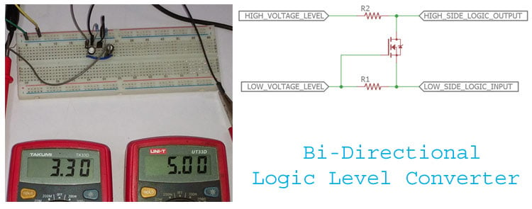
Circuit Digest
Bi-Directional Logic Level converter using MOSFET
 finite hamlet
so im trying to make a portable media player with a pi zero W and so far i am able to connect and play a song on my bluetooth speaker with pulseaudio. but since im running a headless setup I want to utilize the play/pause button on the speaker to atleast have some sort of control.
I am looking into the /dev/input/ directory in hopes of getting it to work with the evdev module but I do not see any event* files while my speaker is connected and playing. How do I approach this?
do bluetooth devices have a different directory for input?
 plush jacinth
 wet prism
I have an ESP32 with a MicroPython script (including urequests) running in an infinite loop. Now my device is installed into a 3D-printed case, and parts are soldered on top of it, so only the USB port is exposed. When developing in C with esp-idf, a connection via USB to the microUSB port of the ESP32 was sufficient to reset it and flash new code. In MicroPython that doesn't quite seem to work, unless I'm missing a command somewhere, you need to physically press the button(s) to reset it. Could somebody point me in the right direction with how to flash the board with the microUSB port only (and automatically)?
 rose pecan
i have no money to buy a microcontroller
gentle vapor
wet prism
I have an ESP32 with a MicroPython script (including `urequests`) running in an ...
if it's in a loop, you should be able to halt the program with ctrl-C from the serial console, and then execute a command on the REPL to force the reset(machine.reset() ?), and it should be possible to automate that
no promises though
 west cypress
New to microcontrollers, can anyone recommend any (that u can use python with)? the cheaper the better
My requirements:
1. Can connect to the internet wirelessly
2. Can control LEDs and other components attached to it
3. Can run off battery power
4. Bluetooth (optional)
 spiral sandal
west cypress
New to microcontrollers, can anyone recommend any (that u can use python with)? ...
spiral sandal
west cypress
New to microcontrollers, can anyone recommend any (that u can use python with)? ...
- psram
wet prism
west cypress
New to microcontrollers, can anyone recommend any (that u can use python with)? ...
the ESP32 can do all of those
 vague sequoia
west cypress
New to microcontrollers, can anyone recommend any (that u can use python with)? ...
vague sequoia
west cypress
New to microcontrollers, can anyone recommend any (that u can use python with)? ...
arduino + pyfirmata or Pyserial

 cedar adder
Hey, I'm new to this, and need some hardware help with microcontrollers. I need a relatively small motherboard with button extension that can be able to run python and connect to the internet wirelessly and use a battery
Any suggestions?
errant wigeon
cedar adder
Hey, I'm new to this, and need some hardware help with microcontrollers. I need ...
A featherS2 might fit your needs: https://feathers2.io/
 waxen sigil
Hello, completely new to programming, want to learn python to make programs for the machines in the place i work, we use Allen Bradley PLC's to do automation, for the interface i want to start learning to use python, will add ohmeters, voltage drops, compare results, then determine if it is ok or no, and send a voltage out to a USB DAC
Where should i start or if you guys know of a good course or online school i can pay.
rigid tangle
brazen meadow
https://learn.adafruit.com/speech-synthesis-on-the-raspberry-pi That may be what...
oh wow thank you...so this converts text into voice..pretty neat
 fervent hornet
brazen meadow
https://learn.adafruit.com/speech-synthesis-on-the-raspberry-pi That may be what...
fervent hornet
brazen meadow
https://learn.adafruit.com/speech-synthesis-on-the-raspberry-pi That may be what...
i make robot
cedar adder
errant wigeon
A featherS2 might fit your needs: https://feathers2.io/
Ok thanks!
pale sigil
viral vault
By buying one, plugging it into computer using attached USB cable, downloading a...
oke i have this 🙂
errant wigeon
Which kind of pi? And what are you aiming to do with it?
 pseudo minnow
@errant wigeon you can see here, if you can help, please do it
I use the raspberry pi 4 model b
waxen sigil
has anyone used this ones?
https://www.mccdaq.com/usb-data-acquisition/USB-1608G-Series.aspx
pale sigil
I have problem with Arduino Uno R3 USB no work
 pine cloud
im working with the raspberry pi pico I have 2 OLED displays set with in a function with their own code but when i call the functions both displays match depending on what function i call they are hooked up to diffident i2c pins is there a way to fix this?

 pseudo minnow
#help-avocado help with my line follower robot on raspberry please?
 sinful mural
Hey, We are going to build and code a ev3 robot and I'm not quite sure if i should choose Python ore MicroPython. Does MicroPython has library-support? And how well does it handle something like opencv?
errant wigeon
pine cloud
im working with the raspberry pi pico I have 2 OLED displays set with in a funct...
This is a long shot, but could you rename one of the 'font_writer''s in the second instance to 'font_writer1'
i2c isn't my best game so I'm first going to search for an issue of accidentally shared memory
errant wigeon
sinful mural
Hey, We are going to build and code a ev3 robot and I'm not quite sure if i shou...
To run a python library in micropython there usually needs to be a port made. Because openCV relies on a lot of compiled c++, I don't know that a simple port is possible. I'm sure you can make a subset of opencv that solves some of your goals, but for the full module it might be easier to just use an embedded linux device like a raspberry pi instead. But that's going to depend on a lot of thing, maybe a small subset is all you need, at which point you're left trying to figure out how well it handles opencv--which is going to depend on the micro you use, how much memory it has, how much power it needs, and how fast you want to refresh the image processing feed
pine cloud
errant wigeon
This is a long shot, but could you rename one of the 'font_writer''s in the seco...
i got it i has to change one of the displays to a I2C1 pin but thank you anyways
errant wigeon
pine cloud
i got it i has to change one of the displays to a I2C1 pin but thank you anyways
Well congrats getting the solution!
 grand venture
guys what is max function in python?
steep dune
if i use a ESP32 or ESP8266 as a full-duplex data link to a external micro controller -- is there enough security in WIFI connection ?
errant wigeon
steep dune
if i use a ESP32 or ESP8266 as a full-duplex data link to a external micro contr...
I am not qualified to talk about wifi signal security, it might be a better topic for the networking and security topic channels, but to start you off, here's a doc from espressif: https://docs.espressif.com/projects/esp-jumpstart/en/latest/security.html
steep dune
i have 2 raspi B+ sitting for a year , i want to tinker with them - they will just be glorified WIFI modems , supplying a ful-duplex data link to a microcontroller - i want to use python 3 all along the way
tinker with raspi for now - replace with a x, y , z later
 glacial stone
steep dune
if i use a ESP32 or ESP8266 as a full-duplex data link to a external micro contr...
glacial stone
steep dune
if i use a ESP32 or ESP8266 as a full-duplex data link to a external micro contr...
enough security for what? to use around your house? to install in a facility? to drive a rover on Mars?
steep dune
read PH , water sensors -- turm water off on , send email or SMS if something critical
empty tank ---
glacial stone
facilities implement private wifi all the time, as long as you're using standard encryption (WPA2 is good) should be fine, bonus points for keeping the SSID stealth, bonus points for MAC addr filtering
basically the WiFi tech is pretty good for security, as long as you use it right
steep dune
small steps - nice to know its doable - thanks
hmmm going to try using a RP3B+ , the GPIO for simple but my main goal is to use the usb-serial to a microcontroller - thinking modular
errant wigeon
The pi can do usb serial communication
hallow igloo
Is pyserial as efficient as using c/cpp code in an Arduino or STM32 series, like in features, speed, and more stuff?
It's been long time since I last used microcontrollers and just realised there's something known as pyserial to operate mcs with python 
 random magnet

 north anchor
I've been banging around with ESP32s and RP2040s in MicroPython and have only two requirements: a bunch of ADCs and the ability to do I2C master-slave. My understanding is that the PyBoard is one of only two microcontrollers that can do the latter (STM32 is the other). The ESP32 doesn't look like it will ever support I2C slave mode, and I've not heard a peep about the RP2040. So I'm now considering the PyBoard...
By my count there's 16 ADCs on the Pyboard. If that's all I want the PyBoard to do (i.e., I'm not concerned with using any of these pins for anything else), can I actually use all 16 as hardware ADCs? Is there something else I should know?
 boreal bane
vague sequoia
arduino + pyfirmata or Pyserial
boreal bane
vague sequoia
arduino + pyfirmata or Pyserial
I couldnt find much source about pyfirmata . Do you have any source suggestion ?
I am actually working on image processing with python opencv . I want to use output variables on Arduino IDE which ı get from python . As ı know pyfirmata is the best way to do it but pyfirmata has a different syntax so ı am looking for any other way.
 eager wasp
Hey does anyone have a tutorial/instructions for OTA updates using micropython for esp8266?
errant wigeon
eager wasp
Hey does anyone have a tutorial/instructions for OTA updates using micropython f...
I don't really know anything about it, out side of a couple of posts online,
https://github.com/pfalcon/yaota8266
https://micropython.org/download/esp8266/
https://docs.micropython.org/en/latest/esp8266/tutorial/intro.html#deploying-the-firmware
I can't find too much.
This might be a question better suited for the micropython forum: https://forum.micropython.org/
since I image it's going to involve a fair amount of nitty gritty
 cinder turret
eager wasp
Hey does anyone have a tutorial/instructions for OTA updates using micropython f...
cinder turret
eager wasp
Hey does anyone have a tutorial/instructions for OTA updates using micropython f...
Setting up OTA on micropython is much easier then Arduino - assuming you are talking about sending code to something on your WiFi. No idea about remote updates.
In the Thonny IDE it's very easy. All you do is write "import webrepl_setup" (one time) in the REPL and follow a couple steps. This creates a small config file on the device. Then you will need to swap to the WebREPL under options and add the ip and password. It worked fine on my esp32. Network will need to be set up first though.
north anchor
Is there a channel somewhere for discussions about MicroPython? I would have thought so but I couldn't find it. I have question which could go here if there isn't a more appropriate place...
steep dune
we use micro controllers - many are using micro python - seems this is the place
 storm wyvern
Hi, could anyone point me in the right direction. I'm learning how to decode control packets from radio receiver.
Got 6 bytes that are supposed to contain four 12bit precision values. (12 , 12, 12 ,12)
any tips on how to extract the 12 bit precision int from that?
Googling far and wide didn't get me anywhere.
 toxic panther
Simple moduloing and bit shifting will do the trick
 digital hedge
dank
errant wigeon
storm wyvern
Hi, could anyone point me in the right direction. I'm learning how to decode con...
What part of this are you having trouble with, do you have the 6 bytes that you're trying to return 4 values from, or are you still trying to get the 6 bytes from the receiver
storm wyvern
got the 6 bytes in a bytearray. I'm having trouble splitting them correctly
errant wigeon
Cool, are you using python or another language? We're going to bitbang it together, we'll need some bit masks as well, but that's just a part of bitbanging really
storm wyvern
micropython
i just managed to finally get one correct value out of it
turns out the byte order in the protocol should be reversed
and then it seems to kind of work
storm wyvern
so if i go: frame[6], frame[5], frame[4] .. etc
then bit mask works:
        control_bytes = Bits(bytes=[self.frame[8],self.frame[7],self.frame[6], self.frame[5], self.frame[4], self.frame[3]] , length=48)
        self.channels[0] = (control_bytes.int & 0x000000000FFF)
yeah, i've tried so many things but was getting garbage out. and even times where it kinda looked like itworked, adjacent channels would "bleed" into the value
on the positive side the whole bitmasks and bitshifts slooowly starting to make sense
errant wigeon
It takes a while to start clicking, and then (much later on) it'll take a while to remember how to use it. But at least for me, it's become my main way I deal with anything byte level. Even if I don't need to, I throw a byte mask (my_byte & 0xFF) just to be extra sure I'm only dealing with a byte at a time
storm wyvern
interesting, that's sounds like a good practice! the above is part of my attempt implement a protocol from pdf spec for the first time and i already have ran into the issue you describe 🙂
god i stil lcan't get over how weird the byte order is. it sends the bits for the 4 channels like:
1111 1111 2222 1111 2222 2222 3333 3333 4444 3333 4444 4444
errant wigeon
I wonder if that ordering is for error resistance.
storm wyvern
the spec does specify the byte order is little endian
don't know why it was chosen, but good for them to pin it for consistency. From my limited understand of endiannes i expected the 12bit blocks to be together
errant wigeon
*shrug*. But nice job slowly debugging it and figuring that out!
storm wyvern
@errant wigeon thank you very much for your support on this!
next step: they send checksum at the end of the packet. going to figure out how to calculate and validate it
errant wigeon
They show the checksum function they're using right?
storm wyvern
yeah, it's mentioned in the spec: 8 bit CRS using CRC-DVB S2 algorithm
errant wigeon
storm wyvern
yeah, it's mentioned in the spec: 8 bit CRS using CRC-DVB S2 algorithm
Looks like there are a few implementations in python online that you can use to check against your implementation if it's giving you trouble
hasty zealotBOT
:incoming_envelope: :ok_hand: applied mute to @hallow igloo until <t:1631243925:f> (9 minutes and 58 seconds) (reason: mentions rule: sent 6 mentions in 10s).
:incoming_envelope: :ok_hand: applied mute to @hallow igloo until <t:1631243926:f> (9 minutes and 59 seconds) (reason: mentions rule: sent 6 mentions in 10s).
:incoming_envelope: :ok_hand: applied mute to @hallow igloo until <t:1631243926:f> (9 minutes and 59 seconds) (reason: mentions rule: sent 6 mentions in 10s).
:incoming_envelope: :ok_hand: applied mute to @rough kestrel until <t:1631243929:f> (9 minutes and 59 seconds) (reason: mentions rule: sent 6 mentions in 10s).
 daring stone
!silence
 prime shadow
well that explains my mysterious pings
hallow igloo
was i pinged?
 foggy slate
Wow, got pinged in plenty of servers😂
 rigid pecan
 lofty cypress
 upper pine
Guys can anyone help me with interfacing hardware with python... in particular a fingerprint scanner... is it compulsory that I must purchase a fingerprint scanner with exposed APIs (costs more than an average fingerprint scanner both online and locally) (weirdly) or can I try to access the device via usblib as long as windows is able to work with it with appropriate drivers installed?
Any help is appreciated! 😊
errant wigeon
upper pine
Guys can anyone help me with interfacing hardware with python... in particular a...
are you looking for something like this?
upper pine
Yesss I did check adafruit out... but the hardware costs alottt.... and I feel it's just tooo costly 😂
I could find it only on Amazon... and it quoted 15k Indian rupees... which is just aloooot (for me)😂
@errant wigeon
which is why I'm thinking there has to be another way to talk to hardware if windows can talk to it
errant wigeon
do you have one in mind? it's hard to say what you'd need without knowing what you're looking at
upper pine
well, I actually don't have one in mind.....
I'm currently collecting information/material and like figuring out how my project needs to go on... and I'm somehow stuck on the very first step of getting a fingerprint read by python 😩
I want to figure out if I can use ctypes to maybe get a normal fingerprint sensor working with python
errant wigeon
What are the conditions of the project: do you need the scanner, or can you simply take pictures of fingers and extract the finger prints that way?
upper pine
umm yess I so need the scanner cas I'm designing a full fledged auth system with it 😂
or like atleast show the working of a full fledged auth system with it
for most online services n all
errant wigeon
aliexpress probably will offer you a selection, but until you know how it communicates, it's going to be really hard to know how much additional money you'd need in other electronics, and how much additional time you'd need to devote to just figuring it out. it's the rough cut of it, cheap things are cheap, but that might mean there's not a whole lot of information on them.
upper pine
ah rip me then
errant wigeon
Not necessarily, but there's a chance it's going to be a struggle. The sooner you choose a candidate scanner the more time you'll have to look it up and see if someone else has gotten it to work for them
upper pine
Soooo I got some great news and thought I'd share it with you @errant wigeon , I found a local Indian company that manufactures fingerprint/iris and a bunch of other biometric scanners for official / government registration purposes. I also found that they expose the SDK for the device. Plus the price of the device is 2k INR(30USD) compared to 15k ada fruit. I'll wrap the C++ SDK around with python and do the rest. I'm soo relieved rn. Thanks for ur help
I was almost ready to download some drivers and decompile them and then scrap through the source to wrap it around python. Glad I don't have to do that now
errant wigeon
upper pine
Soooo I got some great news and thought I'd share it with you <@4591193508515676...
Whoop that's fantastic to hear! That should make the process much nicer to work with!
 mighty eagle
I posted this in the help channel but was referred here.
I've got a raspberry pi zero setup to drive tank tracks. I'm using a socket to connect from another PC and send inputs to the client. Here's the file giving me issues, https://github.com/Niall47/piTank/blob/experiments-with-sockets/client.py
I'm getting this error, which makes me think it can't find the GPIO object from the client() method even though the cleanup() method has no such issues. I thought declaring it outside of a method would allow it to be used globally.
Pin 16 is an LED in case thats relevant here
Resetting GPIO pins
Connecting to server
Traceback (most recent call last):
File "client.py", line 113, in <module>
client()
File "client.py", line 83, in client
GPIO.output(16,True)
RuntimeError: Please set pin numbering mode using GPIO.setmode(GPIO.BOARD) or GPIO.setmode(GPIO.BCM)```
TLDR: How do I ensure I can modify GPIO pins from anywhere in the project? hardy skiff
so uhm is it possible train a ml model in your pc then upload it to arduino uno/nano? any resource would be appreciated
 fast elm
So I just spent an hour wondering why my esp8266 wouldn't flash... Only to suddenly realize "oh.. it's an esp32" #timewellspent
 paper summit
is there anyway i can add more columns to the sqlalchemy without dropping my whole database and rewriting it
class Students(db.Model,UserMixin):
   id=db.Column(db.Integer(),primary_key=True)
   fullname=db.Column(db.String(50),unique=True,nullable=False)
   email=db.Column(db.String,unique=True,nullable=False)
   personal_email=db.Column(db.String,unique=True,nullable=False)
   password=db.Column(db.String(),unique=True,nullable=False)
   dialling_num=db.Column(db.String(),unique=True)
   branch=db.Column(db.String())
   occupation=db.Column(db.String())

   def __init__(self,fullname,email,personal_email,password,dialling_num,branch,occupation):
      self.fullname=fullname
      self.email=email
      self.personal_email=personal_email
      self.password=password
      self.dialling_num=dialling_num
      self.branch=branch
      self.occupation=occupation

   def __repr__(self):
      return f'Student:{self.id} {self.fullname} {self.dialling_num} {self.branch}'
i wanna add some other columns like github linkedin and website ...
 sudden hamlet
mighty eagle
I posted this in the help channel but was referred here.
I've got a raspberry p...
sudden hamlet
mighty eagle
I posted this in the help channel but was referred here.
I've got a raspberry p...
i really dont understand what youre doign here
you set pins to output
then call cleanup and disable their output
then try to use them as output
why are you calling cleanup before client
 fluid ridge
 ember ember
one of my servos rotates the wrong way, i mean if i do simple code like:
#include <Servo.h>

Servo myservo;

void setup() {
  myservo.attach(10);
}

void loop() {
  myservo.write(0);
  delay(1000);
}
it starts doing full rotations (which shouldnt even be possible since it's a 180° servo)
sorry if it's not really python related but i need this for a project with pyfirmata
also i tested with some other code and it works fine with most angles, except for some (like 0) where it does what it did with the code above
 hardy tangle
hey guys , im pretty new to programming , and im looking for some topics i should learn about to use in the robotics domain using python or c++
 gusty leaf
hardy tangle
hey guys , im pretty new to programming , and im looking for some topics i shoul...
gusty leaf
hardy tangle
hey guys , im pretty new to programming , and im looking for some topics i shoul...
so you want to know what you should know in order to work with robotics?
 sly acorn
oh yeah, i found it. I just find out about circuit python. Is it possible to code my arduinos on it? How is it dif from regular python?
sly acorn
ember ember
one of my servos rotates the wrong way, i mean if i do simple code like:
```c++
...
there is Arduino channel. I think they can help u with it. FYI sometimes servo from china is buggy ^.^
hardy tangle
gusty leaf
so you want to know what you should know in order to work with robotics?
yeah
gusty leaf
hardy tangle
yeah
Learn the basics of python
You can't work on robotics using python without knowing python
hallow igloo
i have this project i would like your opinion on it i, i want to make a robotic hand as you can see i finished with the iron working i have a arduino uno a motor controller and two motors i am not sure what i need to buy and what would be best (i know the very basics of python and arduino code)
 sudden hamlet
how are you planning to move the hand
looks like a tendon based approach is most feasible for how you've built it so far
i.e. a string on the back and front
hallow igloo
yeah thats what i was going for
im using plastic strips
and
was planing to use springs to retract the hand to a defalt position
and then pulling the plastic strip
would retract the hand
sudden hamlet
hmm well
springs and string is another apporoach but you can make a pulley system with string to give you control over 'pulling' the hand open as well
hang on a sec
or
this uses bike chain to stay rigid

Another video to share the progress I've made on designing and prototyping my hybrid myo mechanical partial hand prosthetic. This video documents the addition of the splay function.
#robothand #prosthetic hand project #diy
 grave wraith
How viable is this project? I want to create a security camera using my pi zero + camera add-on for my bedroom to prevent housemates stealing.
My idea is to have it pointed toward my door. When motion is detected in the frame the camera will capture a still image and store it on Azure (also learning cloud computing currently and wanting to test its capabilities). I also want to be able to access the camera via IoT services on Azure for a live feed.
ember ember
sly acorn
there is Arduino channel. I think they can help u with it. FYI sometimes servo ...
yeah i dont mind as long as it is for my beginner projecects so i'll just buy 4 more for 10 bucks lol (that might be why they dont work)
 bronze wind
steep dune
bronze wind
steep dune
i more vertical - less round
 charred rune
grave wraith
How viable is this project? I want to create a security camera using my pi zero ...
charred rune
grave wraith
How viable is this project? I want to create a security camera using my pi zero ...
sounds pretty viable to me
 sand river
does the raspberry pi pico need a raspberry pi 4 to work
gentle vapor
you need a computer, any computer, to program it
errant wigeon
sand river
does the raspberry pi pico need a raspberry pi 4 to work
No it doesn't. To program it, as Neradoc said, you will need a computer of some sort, but it doesn't need to be a pi.
errant wigeon
grave wraith
How viable is this project? I want to create a security camera using my pi zero ...
https://www.pyimagesearch.com/2015/11/09/pedestrian-detection-opencv/
https://www.pyimagesearch.com/2019/04/15/live-video-streaming-over-network-with-opencv-and-imagezmq/
https://www.pyimagesearch.com/2019/03/25/building-a-raspberry-pi-security-camera-with-opencv/
These might provide some solid starting points for your setup
sly acorn
hallow igloo
i have this project i would like your opinion on it i, i want to make a robotic ...
Where did u get this pattern? Doesn't look impressive. Try copy the hand from Terminator movie. Hm... for fingers i do not think is a good idea to use servo. Servo itself very big, unless u will find the way to use leverage but here, mb it's better to use oil or pneumatic liner piston? p.s. i am GOD 😛
hallow igloo
sly acorn
Where did u get this pattern? Doesn't look impressive. Try copy the hand from Te...
actually no
first i came up with the idea of how i wanted it to move
then i made the design
and it looks far to shity to be in the terminator movie
but the way it moves in already done
i just need a way to pull a "string" and im asking you all what is the best way to do it
also the right to be called god is not easy to come by
are you sure you are a god
sly acorn
hallow igloo
actually no
oh yeah. deadly sure 🙂 i recently asked the same question. Apperently there is a lot of servo motors of different power, but as rule they are pretty big. Also step motors. It's pretty much depends rather u want them just move or actually hold something. The most chip, relatively small and common is SG90. But I had one, didn't like it. I wanna try DS3218, DS3225 and DS3230. They should be pretty powerful but also much more expansive ^_^
hallow igloo
i was actually planing on like a using a "semi stepper motor" as in it can only lock in at one position
witch ill make the mechanism my self
and for procesor i'll use a arduino connected to a raspberry pi
so in other words
the most regualr ass motor
is fine
i dont need very accurate movement
just decently strong
sly acorn
hallow igloo
i was actually planing on like a using a "semi stepper motor" as in it can only ...
then try SG90. It's chip, if u don't like it u can always through it out. Use analog signal and has 180 degrees rotation range. Well, a bit less then 180, it's chinese 🙂
hallow igloo
okay sorry for being a noob but how dose rotational range matter?
sly acorn
hallow igloo
okay sorry for being a noob but how dose rotational range matter?
depends on construction and where u use it. but in your case u probly can just use leverage to achieve needful length of movement. And I also a nooby a bit 🙂 but still a god 😛
hallow igloo
I AM THE GOD OF monty PYTHON
sly acorn
hallow igloo
I AM THE GOD OF monty PYTHON
oh... nuh I am god of thunder, like thor only without hammer 🙂
hallow igloo
ᚷᛟᛞ ᛟᚠ ᚦᚢᚾᛞᛖᚱ
sly acorn
hallow igloo
I AM THE GOD OF monty PYTHON
mb u can teach me python a bit? i just learned a syntax a bit. Do u use python to code arduino? what u use circuit python?
hallow igloo
also
im not actually verry good at python
i have written some screen scrapers and stuff
hallow igloo
kk
 wary kraken
 ornate bear
Does anyone know a good low-latency streaming solution for rpi? Or is UV4L webRTC still the best going?
ornate bear
just ask your question
 worthy condor
ornate bear
just ask your question
worthy condor
ornate bear
just ask your question
i need help in coding of ardiuno
u reply me
i will tell u the proper info of it later
ornate bear
just ask here in this channel
 restive solstice
anyone familiar with urequests? im trying to make a post request to a google form
req = urequests.request(method='POST', url='https://docs.google.com/forms/d/e/1FAIpQLSddBmmsY23R3EQDZ6rMXS0QKpr2yAXYW73A948B8no220BooA/formResponse', json={'entry.310074266':'pizza'})
whenever i run similar code using the requests library from my pc it works. this code seems to submit the response but the data is not being read
like it comes in that someone responded but it is not reading in the desired response (pizza)
if i try using data=... instead of json=... i just get an error
could i just have a old version or smth
 ivory creek
i'm trying to flip a single bit from 0 to 1 in my arduino code with a python script
this is what I have:
arduino:
void setup() {
  // put your setup code here, to run once:
  Serial.begin(115200);
}

void loop() {
  delay(100);
  Serial.print(x);
  if(Serial.available()){
    x = Serial.parseInt();
    if (x){
      digitalWrite(7, HIGH);
    }
  }
}```python:
import serial
import time
arduino = serial.Serial(port='COM3', baudrate=115200, timeout=.1)
time.sleep(.05)
arduino.write(b"\x01")
arduino.close()```the arduino code works fine, and writes pin 7 HIGH if I open the serial monitor and type in 1
but the python script doesn't work, even though it's on the right port
python says it wrote data, but the arduino doesn't set pin 7 HIGH
gusty leaf
Anyone know where I can begin in python with arduinos and robotics?
 wooden citrus
ivory creek
python:
```py
import serial
import time
arduino = serial.Serial(port='COM3', bau...
wooden citrus
ivory creek
python:
```py
import serial
import time
arduino = serial.Serial(port='COM3', bau...
is '\x01' for pin 7?
ivory creek
wooden citrus
is '\x01' for pin 7?
I actually solved this just yesterday by changing the write line to:
arduino.write(bytes("1", "utf-8"))```oh nice
ivory creek
but I appreciate the help
wooden citrus
so it's actually expecting the 1 as a decimal character O.O
ivory creek
honestly, I'm not really sure why it fixed it
ivory creek
yeah. Now I'm just trying to figure out how to get 9v from my battery to my motor using a relay module
then my AI powered nerf turret should be operational
 undone vigil
hello
 torn yarrow
does anyone know if python strings are null terminated by chance?
pulsar sun
I don't believe they are
 winter herald
yeah I agree w u
 woven harbor
hi
pulsar sun
python strings are objects
 humble kraken
@torn yarrow they're not C strings :D
 untold minnow
How does one program microcontrollers with Python? Does it have to be a certain kind of microcontrollers?
 woeful crypt
Hello i have a general question about arduino
I want to transfer data from the arduino to my nodemcu
Using software serial.h,but i am getting a lot of errors, and i have been stuck w it for a few days
Could someone please help me out
 midnight kayak
Im currently using a Raspberry Pi Zero W in gadget mode to send USB HID events to act as a remote keyboard, but I'm stumped on the mouse side of things. I'd like to be able to provide both relative AND absolute positional data ( 150, 220) or (+51, -111) but I'm stumped right now since it looks like in USB Gadget mode, there isnt any reading of mouse positional data. Any suggestions on where to start? using python and not cpython or circuitpython or anything
torn yarrow
thanks
hallow igloo
anyone here use platform.io
 limber siren
Has anyone played around with MicroPython/CircuitPython as a means to get better performance out of Python?
I think I'll play around with it later today, but thought I'd ask the question to see what I can expect or if someone has had similar ventures into it.
 solid birch
Hi there, this question is a bit out of the norm, I was planning to buy the rasberry pi kit or similar kits. Not sure what they are called. If someone has used it, could they tell me the ups and dows of different devices?
charred rune
Well it would depend on your project
What you want to work on defines what you're going to buy, generally
Unless you just want a full computer system, in which case the rpi 400 I think it's called? The one built into the keyboard. It's probably once of the better choices, that or a full kit of whatever the latest model out now is.
@solid birch ^
 elder willow
hallow igloo
anyone here use platform.io
elder willow
hallow igloo
anyone here use platform.io
not me
elder willow
pulsar sun
python strings are objects
everything in python is an object. functions, classes literally everything
elder willow
woeful crypt
Using software serial.h,but i am getting a lot of errors, and i have been stuck ...
check the baud rate between devices, maybe you send data too fast and the other device can't keep up
woeful crypt
Yeah the baud rate for both is at 4800
But idk it keeps throwing errors
And sometimes the port is not recognized
pulsar sun
elder willow
everything in python is an object. functions, classes literally everything
internally not everything
 final forge
solid birch
Hi there, this question is a bit out of the norm, I was planning to buy the rasb...
final forge
solid birch
Hi there, this question is a bit out of the norm, I was planning to buy the rasb...
What Beef Wellington said...
With a rPi 400 or rPi 3+, 4+ etc, you'll have access to the full python suite. It's just a debian installation for ArmHF...
I've been playing around a bit with the rPi Pico and micropython.... It's also quite nice...
It just depends on what you want to do with it...
final forge
solid birch
Hi there, this question is a bit out of the norm, I was planning to buy the rasb...
The 3B+, 4B+ models are the standard ones... Probably one of those would be where you might want to start.
Unless you want an all in one, and in that case go for the 400...
The 3A+ model is similar to the 3B+ however it does not have an ethernet port. This reduces cost a bit but consider that 98% of STLs out there for cases etc have the B+ models in mind...
The rPi zero (W) is good as well but very, slow compared to the standard models.. I would only use that where space and power consumption was a big issue... Develop on a B+ model and test/implement on a zeroW if that's the form factor you need....
charred rune
final forge
What Beef Wellington said...
With a rPi 400 or rPi 3+, 4+ etc, you'll have acce...
who the hell is beef wellington
errant wigeon
limber siren
Has anyone played around with MicroPython/CircuitPython as a means to get better...
I would not anticipate it to be more performant, micro/circuit python adjust the language to have a very small language footprint, and that frequently comes at the cost of speed in some areas. What kind of performance gains were you thinking of? (Because smaller memory usage is a performance boost if memory is your bottleneck, so maybe that is what you're after)
 jolly axle
something tells me this aint good

^^ that was my code for a camera to be used on a robot ;-;
 elfin terrace
woeful crypt
Yeah the baud rate for both is at 4800
elfin terrace
woeful crypt
Yeah the baud rate for both is at 4800
Try set different speeds
Slower on sender, faster on receiver
woeful crypt
Alrightt, thank you will try that
Also the nodemcu keeps heating,should i add resistors to bring the voltage dowb
steep dune
i have nothing funny to say - keeping you posted
hallow igloo
Someone from the help channel told me to come here and maybe I'd have better luck here. So um, I have a raspberry pi and I wanna use something like a servo motor, but I needs to able to go up and down, not just left and right. Is there anything like this?
errant wigeon
Servo's rotate around an axis, so up and down vs left or right aren't what they do.
This has a lot of basic motor and motion aspects in this: https://openbuilds.com/builds/v-slot™-belt-pinion-example-build.97/
And while it won't work by being powered off of a raspberry pi, it might help you narrow in and describe what you're looking for
hallow igloo
Thanks
 waxen jackal
i was working on a self driving car using arduino and python(i used tenserflow)
did not end wlel
i used a cheap old gopro camera and some ultrasonic sensors for the final model
turns out those ultrasonic sensors were rlly bad
and the car crashed hard
ill restart that project someday
woeful crypt
Hello
Inspite of changing the baud rate
I am recieving garbage values on my nodemcu and i cant send data from arduino to nodemcu
Could someone please tell me where i am making a mistake
errant wigeon
woeful crypt
I am recieving garbage values on my nodemcu and i cant send data from arduino to...
Does it need a pullup resistor for the serial communication?
woeful crypt
I do not know,but i haven't used a pullup resistor
Just the software serial.h library
errant wigeon
woeful crypt
I am recieving garbage values on my nodemcu and i cant send data from arduino to...
which arduino are you using?
woeful crypt
Arduino uno
I followed this code

Arduino Forum
@OP There are many many logical/physical problems in your setup and codes. Therefore, I have preferred to prepare a tutorial for you rather than adjusting.correcting your system. Please, follow the steps; be familiar with the basics of hardware/software UART communications and get a working project. 1. Make the following setup among UNO, NodeM...
errant wigeon
Oohhh
Ok, so the arduino uses 5v logic, and the nodemcu uses 3.3v logic
Are you trying to get both to communicate to eachother, or is it only one reporting to the other?
woeful crypt
I'm trying to get the arduino to communicate to the nodemcu
So i connected pin 2,3 of arduino to pin 4,5 of nodemcu
woeful crypt
errant wigeon
Ok, so the arduino uses 5v logic, and the nodemcu uses 3.3v logic
I connected the 3.3v pin of arduino to nodemcu
Is this where I'm going wrong?
errant wigeon
between the two you'll need to connect ground as well, and you won't need to connect the 3.3v together
Because the arduino gpio goes at 5v, you'll want to make a voltage divider from the arduino's signal to knock it's voltage down a little so the nodemcu can safely read it
But going from the nodemcu to the arduino is a bit trickier, if the node mcu needs to reply and the arduino isn't able to tell what the reply is, you might need to boost it's signal a bit, products like this: https://www.sparkfun.com/products/15439 help with that problem
woeful crypt
errant wigeon
Because the arduino gpio goes at 5v, you'll want to make a voltage divider from ...
Ohhh okayy I'll do that,thanks a lott!!
errant wigeon
Connecting the ground is going to be the most important part of this though as a heads up
woeful crypt
errant wigeon
But going from the nodemcu to the arduino is a bit trickier, if the node mcu nee...
Ohh okayy
If i want only the arduino to send data to the modemcu
Should i still use this?
errant wigeon
then the voltage divider should work, which is just two resistors in series
woeful crypt
errant wigeon
Connecting the ground is going to be the most important part of this though as a...
Yes i connected the ground of the arduino to the nodemcu
Is that what you are referring to?
errant wigeon
Correct
woeful crypt
errant wigeon
then the voltage divider should work, which is just two resistors in series
Alrightt
Could you please explain to me why the voltages matter cause i am not getting a clear idea
errant wigeon
Yeah no problem
woeful crypt
Do i have to read up on the CMOS used ?
errant wigeon
do you have a few resistors on hand?
woeful crypt
Nope i don't have it right now,i will go tomorrow and buy them
errant wigeon
Ok, so we're going to use a resistor based voltage divider.
Basically, if I have a 5v signal, and then have 5 1k resistors in series, I can check the voltage between each one in between the 5v level and the ground
5v - -vvv- -vvv- -vvv- -vvv- -vvv- -GND
make sense so far?
woeful crypt
Yess makes sense!!
errant wigeon
Ok cool, so if we measure along in between each resistor, you end up with something like this:
5v -  -vvv-  -vvv- -vvv- -vvv- -vvv- -GND
            |4v   |3v   |2v   |1v    |0v
Since resistors drop voltage linearly, we can use it to change a signal at some input voltage to some other smaller voltage, we just need to calculate what resistors we need
And because they come in a lot of sizes, you don't need 5 resistors, you can just use too
woeful crypt
Ohhh okayyy, i understood it thank you so much
Also, we are getting it down to 3.3 V because the nodemcu operates on 3.3V too??
errant wigeon
So lets say we're going for 3v logic levels instead of 3.3, we could just use a 2k resistor, and a 3k resistor connected up, and between the two you would put that to the node mcu
woeful crypt
woeful crypt
Ohhh okayyy, i understood it thank you so much
Also, we are getting it down to ...
And if the voltage levels dont match you can't send the data?
errant wigeon
arduino TX -  -vvv- o -vvv- -GND
                    |         |
                   NODEMCU RX,GND
the first resistor would be 2k, the second would be the 3k
so every microcontroller can see a pin change with some degree of accuracy. If it's a 5v logic chip, it can tell a 0 is a 0, and 5v is 5v, but the middle range, about 3 v, it has trouble determining if it's a 0 or if it should be a 5v signal
that's why you have to pay attention to level shifts between microcontrolllers
errant wigeon
woeful crypt
And if the voltage levels dont match you can't send the data?
you can /send/ data, but you don't know if it'll be understood
woeful crypt
errant wigeon
that's why you have to pay attention to level shifts between microcontrolllers
Ohhh i did not know this
Thanks a lottt!! 😁
woeful crypt
errant wigeon
```
arduino TX - -vvv- o -vvv- -GND
| |
...
So with this at nodemcu the drop falls?
errant wigeon
so the node is getting 5v when it only wants 3.3--it should be able to tell that it's a input and not a 0, but because it's getting a lot more voltage than it wants, it might be causing some power issues elsewhere in the circuit causing your signal issues
The voltage divider probably isn't the exact reason you're having issues, but it is important to use so we don't need to worry about weird power problems as we debug the next bit
You're making sure you're connecting the arduino tx to the node mcu rx right?
woeful crypt
errant wigeon
so the node is getting 5v when it only wants 3.3--it should be able to tell that...
Alrightt
Just a question, what exactly was happening when i connected the 3.3 V pin pf arduino to nodemcu? Was it making a difference?
errant wigeon
so that's not somethign you want to do
woeful crypt
errant wigeon
You're making sure you're connecting the arduino tx to the node mcu rx right?
Not directly using the software serail.h i used pins 2,3 of arduino to nodemcu 4,5
2(rx) to 5(tx)
errant wigeon
you mentioned it was oddly hot, I'm not 100% sure, (because tying different voltage levels together something I'm not good at) but ... ok that's different one moment, I'll finish this thought then I'll describe the serial comms pins
woeful crypt
Okayy
errant wigeon
so if you connected the two power pins together, you'd end up with some weird competition. Basically the voltage levels are maintained by a voltage regulator. It's a device that tries really hard to keep the voltage at a very specific level, but it's a real part in the real world, so the regulators can sometimes be a bit different. Some will keep it at 3.28, others at 3.304, etc. Those little differences can cause competition if there's nothing between the two to absorb the difference. Most of the time the competition isn't that big of a deal, but it can cause weird things. If you put a resistor between to perfect but different 5v sources (who's grounds are tied together), then there will be no current flowing across the resistor at all, and it'll use no energy. But if there's a small amount of difference between the two 5v sources, the resistor can take that difference, allow current across, and 'drop the load' between the difference of the two real 5v (with real imprecision) power sources. That's a good buffer between the two 3.3 v pins, but in practice, you almost never need to tie two voltage regulators like that together unless you're doing some power focused project (it happens a lot more now that folks are making at home batter charging banks, but we'll assume you're not going to explore that area yet)
But for the logic pins on the TX and RX, it isn't a voltage regulator that you're tying together
When you're connecting the TX of one uc to another's RX, the first (the TX) is a pin which is set to an output. That mean the microcontroller is only going to tell the pin to output either 0v or VCC (5v or 3.3v or whatever it's logic level is)
The RX pin is listening for the voltage across it to change, either to it's high volt level, or close to it's ground level
woeful crypt
Okayy this makes a lot of sense
Thank you so much, I'm getting a clearer as to what is going on
This voltage regulator is inbuilt in both the nodemcu and the arduino right?
errant wigeon
it has a resistor that drops the input on it to ground to dissipate the energy, but like you can measure voltage on the series of resistors we were talking about, it can tell if the voltage is high or low
Here's a few much more comprehensive explanations as well: https://forum.arduino.cc/t/how-is-the-state-of-a-gpio-pin-detected/237312/2
errant wigeon
woeful crypt
Okayy this makes a lot of sense
Thank you so much, I'm getting a clearer as to ...
When you say 'this voltage regulator' what do you mean? (Just so I'm sure I haven't miscommunicated something)
woeful crypt
The device that tries to maintain the power (5V/ 3.3V) at a constant voltage level
errant wigeon
ah, yes, give or take. It gets nitty gritty, and stops becoming completely true as you learn more about the lower level stuff, but for your ability to think of what's going on that'll work
The device has a limited amount of power and current it can provide, so if you exceed that current on a pin, you'll start to run into some weird issue caused by power failures called browning out
woeful crypt
errant wigeon
The device has a limited amount of power and current it can provide, so if you e...
Ohhh😬😬
errant wigeon
Unless you're putting a ton on it, you won't have to worry
woeful crypt
errant wigeon
it has a resistor that drops the input on it to ground to dissipate the energy, ...
Alrightt, thank you so much for this explanation!!😊
Was extremely helpful
I will read the article ,and try this out tomo
woeful crypt
errant wigeon
Unless you're putting a ton on it, you won't have to worry
Okayy
errant wigeon
awesome! Chance are there's another issue, but with improper logic levels it makes it a lot harder to find the real issue, so I figured this was a good place to start debugging
woeful crypt
Okayy, yeahh i tried changing the baud rate many times but i did not do anything related to the voltage levels
Also, the 3.3 V and 5 V pins on the arduino are the output pins which are voltage regulated (if i got it correctly )
errant wigeon
Umm, the only connections you should need are
a wire between the arduino TX and the nodemcu RX (which will have a voltage divider)
a wire between the ground of both uc
woeful crypt
Okay yes
But should i connect it directly? i thought i shouldn't do that since im using the software serial library
errant wigeon
I'm afraid I don't quite follow what you're asking
I think I was unclear, which ever pin you're using as the RX, that's the one you connect to
woeful crypt
Pin 0 and pin 1 of arduino are hardwired as rx and tx so i am not using those
I got your point, i will try it with a single wire
I was using two wires
errant wigeon
Make sure there is one wire tying ground together, give me a few minutes, I should be able to get a picture of what it should look like
woeful crypt
Yes yes i will
Okayy
errant wigeon
The wiring here is highlighted for just the connections, Red is the TX signal from the arduino, peach is the first resistor in the voltage divider, green is the middle of the voltage divider that goes to the RX of the node MCU, blue is the second resistor in the voltage divider, and black is the ground

Here it is without the highlights and just wired up. Not the best angle, but it should clarify how the two should be wired

I don't have a node mcu so I choose something with a similar form factor. I randomly selected pins for the signal though because I don't have the pinout of the node mcu, your circuit will probably have a different pin connection/selection
limber siren
errant wigeon
I would not anticipate it to be more performant, micro/circuit python adjust the...
I had some time to re-evaluate this today and look into it more. Mostly what I was considering was the memory aspect but with your explanation of "very small language footprint, and that frequently comes at the cost of speed in some areas." it seems like I would just be using the wrong tool for the wrong job.
woeful crypt
errant wigeon
The wiring here is highlighted for just the connections, Red is the TX signal fr...
Thank you so much ,i understood the connections!!
I was talking about the red wire. I had connected it to pin number 3 and using software serial.h library, had given it the function of tx
I will rig this circuit up and try it
I think this is where i have made the mistake
I will change my connections and the code
woeful crypt
errant wigeon
I don't have a node mcu so I choose something with a similar form factor. I rand...
Heyy, i tried your connections and i am getting the data !! Thanks a lot😁
But there is one more problem i can't figure out
The nodemcu is able to read only 3 lines of code after which it throws errors again
Is there an issue with my code? Or should i debug my connections again?
errant wigeon
woeful crypt
Heyy, i tried your connections and i am getting the data !! Thanks a lot😁
But t...
3 lines of code or 3 lines of communication from the arduino?
Also whoop! Congrats on getting a bit further, that's great!
woeful crypt
errant wigeon
3 lines of code or 3 lines of communication from the arduino?
3 lines of communication from arduino
I can show you the pictures of my code and the output
woeful crypt
errant wigeon
Also whoop! Congrats on getting a bit further, that's great!
Haha thank youu!! 😊🙈
errant wigeon
if you could, can you post the code?
If it's too long, use https://paste.pythondiscord.com/
if not you can paste it here
hasty zealotBOT
Hey @woeful crypt!
It looks like you tried to attach file type(s) that we do not allow (.ino). We currently allow the following file types: .gif, .jpg, .jpeg, .mov, .mp4, .mpg, .png, .mp3, .wav, .ogg, .webm, .webp, .flac, .m4a.
Feel free to ask in #community-meta if you think this is a mistake.
woeful crypt
#include<SoftwareSerial.h>
//#include <ESP8266WiFi.h>
SoftwareSerial SUART (4); //conneted to D2
void setup() {

  // put your setup code here, to run once:
  Serial.begin(9600);
 SUART.begin(9600);
}

void loop() {
  // put your main code here, to run repeatedly:
  //String msg = mySerial.readStringUntil('\r');
  //Serial.println(msg);115200
  //byte n = mySerial.available();
  if (SUART.available())

  {
   char x= SUART.read();
   Serial.print(x);
   delay(100);
}
 else
  {
  Serial.println("error");
  delay(100);
  }
}
this is the code for nodemcu
woeful crypt
errant wigeon
if you could, can you post the code?
If it's too long, use https://paste.python...
Okayy i have posted the nodemcu code here and pasted the code for the arduino using the link
I think i am making a mistake using software serial.h and the arguments i am giving in it
errant wigeon
what is the output you get from the node mcu?
woeful crypt
I get this-"the distance from the target is 74.27 and the servo angle is" after which it only shows error until i press reset
woeful crypt
errant wigeon
what is the output you get from the node mcu?
I tried sending just " hello from arduino" at first
Nodemcu would output this 3 times perfectly but later show garbage values
errant wigeon
could you show me the output? that the nodemcu prints?
woeful crypt
errant wigeon
could you show me the output? that the nodemcu prints?
I unfortunately did not take a picture of the output :/ i dont have any of the components with me rn so i can't rig it up and show
errant wigeon
Ok, no worries. I just can't quite guess what the error is without knowing what the garbage values are--sometimes it's specific garbage that's very informative, sometimes it's just noise
does it ever print 'error'?
and why are you using delay? (I've never used it, it's a new one to me)
woeful crypt
For the "Hello from arduino "
After a point it would show
HHHHHHH
errant wigeon
Always H?
woeful crypt
errant wigeon
Ok, no worries. I just can't quite guess what the error is without knowing what ...
It did print it error cause we have given it in else

Okay my friend had taken it😅
woeful crypt
errant wigeon
Always H?
Umm yeah
And sometimes it would start showing from "from arduino"
errant wigeon
does it ever start working again after running for a while?
woeful crypt
Since the output was coming too quickly we used delay function to slow it down
woeful crypt
errant wigeon
does it ever start working again after running for a while?
Nope, when i press reset it starts working again
errant wigeon
can you remove the delay from the if suart.available() block?
woeful crypt
When i removed the software serial SUART and directly connected it to nodemcu rx it showed an error of board not being detected
woeful crypt
errant wigeon
can you remove the delay from the if suart.available() block?
After serial.print?
errant wigeon
yes
woeful crypt
I did try w/o the delay at first
errant wigeon
I'm wondering if the arduino is sending too many messages too fast, and it keeps overflowing
woeful crypt
It was just showing error continuously, and when i press reset it would show "arduino"
errant wigeon
it would say error, since there's nothing recieved. You can comment that statement out for the moment
woeful crypt
errant wigeon
I'm wondering if the arduino is sending too many messages too fast, and it keep...
Yess! I was thinking the same
But i cant understand how /why that is happening or how to debug it
woeful crypt
errant wigeon
it would say error, since there's nothing recieved. You can comment that stateme...
Okayy
errant wigeon
additionally, try making the arduino sleep for 1 second between each transmission
woeful crypt
How do i do that?
errant wigeon
that'll help us make sure the arduino doesn't seen too much
In the loop for the arduino, just add a delay(1000);
woeful crypt
Like in the void loop itself?
errant wigeon
yes
woeful crypt
errant wigeon
that'll help us make sure the arduino doesn't seen too much
In the loop for the...
Do you think i have done a mistake in the software serial part?
Cause i tried removing that and connected the pin directly to rx of nodemcu
But it showed an error saying board not detected
woeful crypt
errant wigeon
yes
Okay, could you please tell me where in the void loop🙈in the beginning?
errant wigeon
Did the computer day board not detected, or did the node mcu say board not detected?
You haven't posted the arduino's code yet, just the node mcu
woeful crypt
errant wigeon
Oh maybe you did, let me look
😂😂
woeful crypt
I'll just paste it here?
errant wigeon
yeah go for it
errant wigeon
woeful crypt
I thought i pasted it in the link
Oh you get a url once you save the code, unless I have that I can't see it
woeful crypt
errant wigeon
Did the computer day board not detected, or did the node mcu say board not detec...
When i ran the nodemcu code the compiler said the board not detected for some reason
errant wigeon
woeful crypt
When i ran the nodemcu code the compiler said the board not detected for some re...
so for that, disconnect the wires to the node mcu while you're uploading code, upload it, and then you can reconnect the wires
errant wigeon
woeful crypt
https://paste.pythondiscord.com/mahowoyaze.py
Looks like you send a message only once every 10 seconds + 1 second for the ultrasonic sensor
are you waiting that long before you reboot when you're testing it?
woeful crypt
errant wigeon
so for that, disconnect the wires to the node mcu while you're uploading code, u...
Yes yes that is exactly what i did
woeful crypt
errant wigeon
Looks like you send a message only once every 10 seconds + 1 second for the ultr...
Yeah
woeful crypt
errant wigeon
are you waiting that long before you reboot when you're testing it?
I did not get you
errant wigeon
woeful crypt
Yes yes that is exactly what i did
did you try again in that case? Sometimes it's just glitchy
woeful crypt
woeful crypt
I did not get you
I never tried testing it without the delay in the arduino
errant wigeon
woeful crypt
I did not get you
Sorry, that was unclear.
When you say the nodemcu isn't getting the messages, did you wait more than 10 seconds to see if a new message came in from the arduino?
woeful crypt
errant wigeon
did you try again in that case? Sometimes it's just glitchy
Yeah i tried it twice until i stopped and had to restart the laptop
errant wigeon
how long did you wait before you stopped?
woeful crypt
errant wigeon
Sorry, that was unclear.
When you say the nodemcu isn't getting the messages, di...
Okay yeah i think so
It would show error and then distance and then the error again
errant wigeon
woeful crypt
Okay yeah i think so
It would show error and then distance and then the error a...
Oh!
I think it's working then!
That's what your code says to do
So, let's break it down
Looking at the arduino first, you have a delay of 10 seconds present. So it only does things once every 10 seconds, and when it does stuff it takes a second to read from the ultrasonic sensor
so once per 11 seconds it'll send a message
On your nodemcu side, it'll print the message when it gets it. But once it's done printing, and once there's nothing in the serial buffer, your code says to print 'error'
it's able to print the arduino message pretty quickly, (less than a second)
so after that, there's nothing else to do but print 'error' until the arduino sends another message (about 11 seconds from that point)
woeful crypt
Ohhhh alrightt thanks a lott!!
If i want to send it instantaneously what would i have to do?
errant wigeon
well, the ultrasonic sensor needs to wait a full second to get it's reading according to the way you setup the code
woeful crypt
Is it possible cause i have the ultrasonic too and i want that part to sense slowly
errant wigeon
so one message a second is about as fast as you can send things
woeful crypt
Oh okayy
errant wigeon
now you can have an error that prints if you haven't received any message within a given time frame
woeful crypt
Yess
I will try this tomorrow, waiting for a min to see my output
But i am not able to understand the part where it just shows HHH when i send hello from arduino( is it cause i haven't used a delay for that code and the arduino is sending a lot of data at once?)
errant wigeon
That bit is a bit confusing to me too
I want to see what it looks like, and the arduino code you're using that generates it
errant wigeon
woeful crypt
I will try this tomorrow, waiting for a min to see my output
But i am not able t...
is it cause i haven't used a delay for that code and the arduino is sending a lot of data at once?)
I think that's the cause honestly
Knowing that the sensor code works, and that we're getting the correct messages from it makes me pretty confident that you're overflowing the nodemcu by not delaying a bit between sends, and by having the node mcu delay between prints
 frank cloak
@woeful crypt check your board baud rate
woeful crypt
 errant wigeon
frank cloak
<@696373334119546890> check your board baud rate
errant wigeon
frank cloak
<@696373334119546890> check your board baud rate
I don't think it's that
woeful crypt
errant wigeon
I want to see what it looks like, and the arduino code you're using that generat...
I don't have a picture of that output but this is the code i used
errant wigeon
ok you've got a delay there.
woeful crypt
errant wigeon
Knowing that the sensor code works, and that we're getting the correct messages ...
Ohh okayy, i also have a question
In my nodemcu code i have declared char x is it incorrect if i use char x[] cause that gave me errors too
frank cloak
Use 115200 baud rate with node mcu
woeful crypt
errant wigeon
ok you've got a delay there.
But is half a second too less?
errant wigeon
woeful crypt
But is half a second too less?
It shouldn't be. Micros are pretty quick.
woeful crypt
Initially when i was using software serial for arduino too, i had given pinmodes for pins 2 and 3,i dont get why i don't have to that for nodemcu
woeful crypt
frank cloak
Use 115200 baud rate with node mcu
I tried it w that, doesn't work
It outputs "???"
errant wigeon
woeful crypt
I tried it w that, doesn't work
It outputs "???"
Both micros need to be on the same baudrate, you were on the same baud beforehand, and since you're getting communication between the two I really don't think the baud is the issue
woeful crypt
Yeahh the baud rate isn't the issue
I did use the same baud rate
frank cloak
Can you check the COM port from device manager ?
errant wigeon
I think the issue is more tied to how we're reading from the nodemcu serial rather than a connection issue
woeful crypt
Do you mean the char x part? Or that i have used pin 4 as SUART?
frank cloak
The ESP8266 has two hardware UARTS (Serial ports): UART0 on pins 1 and 3 (TX0 and RX0 resp.), and UART1 on pins 2 and 8 (TX1 and RX1 resp.), however, GPIO8 is used to connect the flash chip. This means that UART1 can only transmit data.
errant wigeon
woeful crypt
```c
#include<SoftwareSerial.h>
//#include <ESP8266WiFi.h>
SoftwareSerial SUART ...
while (SUART.available()){
   char x= SUART.read();
   Serial.print(x);
   }
Try adjusting the code to this, it should help make sure we clear the buffer before we exit out in the loop
woeful crypt
Alrightt!! I will do this thank youu:))
woeful crypt
errant wigeon
```c
while (SUART.available()){
char x= SUART.read();
Serial.print(x);
...
Could you please explain to me what happens when char x is declared as an array
errant wigeon
woeful crypt
Could you please explain to me what happens when char x is declared as an array
So this bit is just declaring x as a character
serial read returns a byte at a time, so it's just using one byte per character, then in the next line you're printing that character. Because there's not added new line character, the next character you print gets put in right next to it when you look at it in your serial read port
A character array (string) on the other hand is an array whose elements are of the type, 'char'. you can have integer arrays as well (and you can get crazier pretty easily)
woeful crypt
errant wigeon
serial read returns a byte at a time, so it's just using one byte per character,...
Okayy yess
frank cloak
Have you added that json file in board preferences URL ?
Json dedicated for esp8266 board configuration
woeful crypt
errant wigeon
A character array (string) on the other hand is an array whose elements are of t...
Right, so to read the entire string in the array i will have to modify the code?
woeful crypt
frank cloak
Json dedicated for esp8266 board configuration
Yes i did
woeful crypt
frank cloak
The ESP8266 has two hardware UARTS (Serial ports): UART0 on pins 1 and 3 (TX0 an...
Ohh okayy
errant wigeon
So when declaring it as a character array, you're telling the computer this is going to be an array of elements who's contents are characters. But your computer needs to know how big it is, or be told to get a little bit more memory than it had and add this to it. In c that last option is a bit more difficult
https://www.arduino.cc/reference/en/language/variables/data-types/array/
This is a good intro on the datatype
errant wigeon
woeful crypt
Right, so to read the entire string in the array i will have to modify the code?
We'd want to store the values somehow, so yes we'd modify it in some way. But you can also parse the incoming string and look for the values you're interested in and only store those instead of the full string. Or you can save the full string, and as you get more just refill the buffer. There are options, it just really depends on what you want to do with the information from the serial input
woeful crypt
errant wigeon
So when declaring it as a character array, you're telling the computer this is g...
Ohhh alrightt
I gave it like this char x[1000]
I will check out the link, thankss
woeful crypt
errant wigeon
We'd want to store the values somehow, so yes we'd modify it in some way. But yo...
Ohhh, i hadn't thought about any of these
I will read up more on this
I want to send this data to the cloud and finally plot a graph
Thank you so much!!
errant wigeon
woeful crypt
Ohhh, i hadn't thought about any of these
I will read up more on this
I want to...
That's very doable! And there's lot of ways to make it happen! We'll take it a step at a time though and get a better look at the serial communication issues. But there are thousands of ways to do it
frank cloak
woeful crypt
Ohhh, i hadn't thought about any of these
I will read up more on this
I want to...
Convert your data into json if you want to deploy it over cloud. I worked on AWS IoT Core and analytics with nodemcu sensor data monitoring and plotting
 pulsar marsh
Anyone has maybe 30 mins to help a stupid noob? 🤦🙈

Basically i got in micropython only the epaper display working 🤦
And i need to get the rest working either 😬🤣
woeful crypt
errant wigeon
That's very doable! And there's lot of ways to make it happen! We'll take it a s...
Heyy, you were right!! The code is working
I removed the error and it was finee
Just had another question, how do i parse the data that i am getting
Everything is stored in the variable x , so how should store that in csv file or transfer to thinkspeak
midnight kayak
Does anyone have a solution for controlling a mouse/keyboard via a usb receiver from Python? This would be from a separate machine entirely
woeful crypt
errant wigeon
We'd want to store the values somehow, so yes we'd modify it in some way. But yo...
Could you also please tell me more about this
hallow igloo
woeful crypt
Could you also please tell me more about this
I will tell you more, what do you need?
 lost lion
User banned. Sorry about them @woeful crypt.
errant wigeon
woeful crypt
Could you also please tell me more about this
I'll be free to explain it in more depth later on, bit busy today
This should help outline it: https://forum.arduino.cc/t/arduino-serial-to-variable/37458
basically you'll want to take in incoming string, and store the values you want as a varible of some sort, a float or an array.
Then you'll want to connect to the internet and post the value to the site you're after: https://tttapa.github.io/ESP8266/Chap07 - Wi-Fi Connections.html
I have no idea how to use thingspeak, but this tutorial looks helpful https://nothans.com/thingspeak-tutorials/arduino/send-data-to-thingspeak-with-arduino
errant wigeon
midnight kayak
Does anyone have a solution for controlling a mouse/keyboard via a usb receiver ...
It sort of depends on how far away you are from the machine
 fiery anchor
Is it possible to use a windows 10 laptop as a monitor for a raspberry pi using an hdmi? I can only find solutions that use ssh on Google
I’ve done it with vnc before but it would be easier to just plug it into any laptop
errant wigeon
fiery anchor
Is it possible to use a windows 10 laptop as a monitor for a raspberry pi using ...
No, the hdmi port will not take the pi's display as input, it'll be output only. The closest you're going to get is setting up the pi to be capable of being a remote desktop and logging in on your pc over the network using something like you have before--vnc. Now you can connect an ethernet cable between the laptop and the pi to have a faster connection, but vnc is still going to be one of the few ways you can use the laptop as a monitor
Something roughly like this: https://www.instructables.com/Set-Up-Raspberry-Pi-4-Through-Laptoppc-Using-Ether/
fiery anchor
errant wigeon
No, the hdmi port will not take the pi's display as input, it'll be output only....
Ok Thanks
sand river
i tried installing machine with pip install machine but it gave me an error saying failed building wheel for pycrypto
woeful crypt
errant wigeon
I have no idea how to use thingspeak, but this tutorial looks helpful https://no...
Thank you so muchh!! Will refer all of these😊
midnight kayak
errant wigeon
It sort of depends on how far away you are from the machine
This would be from a range of no more than several feet. I was able to set up a RPI Zero W as a gadget with a socket connection to listen and pass commands to a small script to act as a HID usb controller for the mouse, but it's sort of a janky process that doesn't allow for concurrent keypresses or held keys, and no mouse control. It's a start for sure, but I was wondering if there was something out there I could use as a framework, or if there was a better way (direct radio/bluetooth broadcast to a USB receiver perhaps?)
errant wigeon
midnight kayak
This would be from a range of no more than several feet. I was able to set up a ...
HID is the way to go, https://learn.adafruit.com/customizing-usb-devices-in-circuitpython
That should help outline the protocol more
steep dune
that is so COOL!
hallow igloo
Can somebody help me understand how the tuya or anyother smart device is get discovered by it's specific smartphone application? When we turn on Bluetooth or WiFi we don't see the smart iot Device there but the device/product application does discover it, Just help me understand the theory at least
steep dune
hmmm - is there a way to intercept data traffick between the 2 devices ?

SourceForge
Download Wireshark for free. We no longer host here. Please use https://www.wireshark.org. Official releases can be found at https://www.wireshark.org/
Wireshark is a powerful network protocol analyzer developed by an international team of networking experts. It runs on UNIX, OS X and Windows.
how do you intercept radio traffick
????
pfSense is a firewall/router computer software distribution based on FreeBSD. The open source pfSense Community Edition (CE) and pfSense Plus is installed on a physical computer or a virtual machine to make a dedicated firewall/router for a network. It can be configured and upgraded through a web-based interface, and requires no knowledge of the...
can this show real data - then kinda ' reverse engineer
????
 blazing sinew
@hallow igloo Could be using NFC instead of BT/Wifi
 pure osprey
ok, my micropython code is somehow exiting a while loop before the condition is met...
hallow igloo
blazing sinew
<@456226577798135808> Could be using NFC instead of BT/Wifi
LOL, no They don't use NFC for that, also i am not specifically asking about Tuya products, I am asking in general How IoT devices get's the wifi Credentials from the phone app and then After successfully connecting to the Network, How they let the app know that they are connected
pure osprey
hallow igloo
LOL, no They don't use NFC for that, also i am not specifically asking about Tuy...
its a firmware they wrote for the board
you litterally have to use two boards to program using tuya
hallow igloo
pure osprey
its a firmware they wrote for the board
Nice, Pretty smart people are around here in this server
pure osprey
yup
you have to have a esp-based chip running tuya firmware, and then any other arduino controlling everything else using their i2c library to talk to the esp chip.
the ESP chip manages the wifi smart connections, and the tuya server, then relays instructions to the arduino controlling the rest.
hallow igloo
Did i asked how to Build that?
pure osprey
I wanted to hook a door lock to tuya services, and I couldnt cause I dont have space for two arduino's in the lock.
pure osprey
hallow igloo
Did i asked how to Build that?
no, but it was interesting info
hallow igloo
😆
pure osprey
so if you ever do want to connect a python project to tuya, you can! 😁
hasty zealotBOT
Hey @pure osprey!
Uh-oh! It looks like your message got zapped by our spam filter. We currently don't allow .txt attachments, so here are some tips to help you travel safely:
• If you attempted to send a message longer than 2000 characters, try shortening your message to fit within the character limit or use a pasting service (see below)
• If you tried to show someone your code, you can use codeblocks
(run !code-blocks in #bot-commands for more information) or use a pasting service like:
pure osprey
dag nabbit
there is my code. The while loop in lock() keeps exiting the loop after 2-5 iterations, not completing the lock function properly.
idk why
the analogToPin class could be the issue, IDK either.
can someone help please?
seems to be hardware...
I put an LED command instead of a motor, and it worked just fine.
pure osprey
idk what is wrong. I've tried several hardware configurations, even different pins. Still no change. Turns clockwise just fine, will not work counter-clockwise
pure osprey
Ok, how do I do PWM in micropython?
I see the set duty cycle, frequency, etc. But how do i turn it on and off? Does setting a frequency just automatically turn it on?
 shy roost
Hello, one question please.
I am doing a robot, and i want to do 2 threads one to get analysis from sensors (camera), and another to communicate with an Arduino (with variables obtained from the analysis part), to move motors etc..
The idea is that the analysis thread is always on, so the robot always gets info from the environment, and the communication sends information only when this variables get some value.
I read about semaphores, but I am not sure if this is the right way to do this. So my question is what is the best way to do this, and are threads necessary, instead of just calling a function for sending communication.
Thanks a lot in advance.
 neon flame
hi how do i configure 3 flow sensors and 3 temperature sensors to my raspberry pi and gather data at 3 different locations
any tutorials or help guides please thank you.
woeful crypt
hallow igloo
I will tell you more, what do you need?
I tried looping through the data i recieve but i don't get any output and it is a blank on the monitor
If

This is my code but idk where i am going wrong
woeful crypt
errant wigeon
This should help outline it: https://forum.arduino.cc/t/arduino-serial-to-variab...
Hello,i tried the code but i think i am messing up in a lot of places, could you please guide me again
woeful crypt
I tried sending the distance values and the nodemcu reads each character at a time, I'm confused about how i should send the integer value as a whole
Before that i tried putting the entire data stream in am array and printing it,the monitor again shows garbage values
pure osprey
ok, can someone help me with this?
I am setting a variable in the script as a global variable, and I run a function that is supposed to change the global variable, and it does in the variable (ex. if I print from the function) but the moment I check the variable within the python shell in thonny, it returns as the original value.
final forge
After someone who might be able to explain a little bit about how micropython works.
Initally, I'm curious to know where the base filesystem is stored on microcontrollers.
My esp32 with micropython is reporting 2Mb of FS space (os.statvfs).
Does the micropython image take up 2Mb and then create another 2Mb partition for scripts etc?
frank cloak
Does anyone know how to use Cython to deploy python code onto arm cortex M4 based controllers ?

I want to build compiled python based application on this development board Nucleo F429ZI
 twilit wharf
Have any one work with raspberry before and have issue with getmac
 static anchor
can I ask smt about rpi zero w?
need help with smt
how can I make it play sound off of my phone's speaker?
insted of a buletooh speaker?
anyone?
 merry mulch
static anchor
can I ask smt about rpi zero w?
need help with smt
how can I make it play sound ...
merry mulch
static anchor
can I ask smt about rpi zero w?
need help with smt
how can I make it play sound ...
I would not expect a phone to act as a bt speaker. But maybe you can webserve a file for the phone to play.
 thorny patrol
Hello, m new here, so m planning to start my Arduino project does anyone of u know how to program an arduino with python?
twilit wharf
I keep having this issue , i have tried pip3 install getmac and it still appear
 static anchor
merry mulch
I would not expect a phone to act as a bt speaker. But maybe you can webserve a ...
static anchor
merry mulch
I would not expect a phone to act as a bt speaker. But maybe you can webserve a ...
how can i do that
can you help guide me wiht it pls
 cyan haven
Where can i learn micropython
merry mulch
static anchor
how can i do that
your questions are quite broad and can be interpreted quite widely so it's hard to help. But maybe you can python -m http.serve in a directory which contains playable audio files then access your pi zero from safari on ios / chrome on androlid
merry mulch
cyan haven
Where can i learn micropython
go to their website, download, install, run some tutorials?
cyan haven
Thank you
merry mulch
cyan haven
Thank you
I know you can play with micropython on your laptop
without an actual microcontroller
cyan haven
merry mulch
without an actual microcontroller
Well i need it for the raspberry pi pico and esp8266
merry mulch
cyan haven
Well i need it for the raspberry pi pico and esp8266
Are you looking to learn micropython or learn about the MCU?
merry mulch
then you can start playing with micropython on your laptop without the MCU if you wish
or, you can run the micropython REPL and play with the MCU live
cyan haven
What is REPL
merry mulch
have you tried typing python in the terminal then 2+2 followed by enter?
cyan haven
Yes
merry mulch
then you have used the regular python REP(read evaluate print loop)
micropython lets you run one on your MCU I think
merry mulch
sure if I can - just ask and then anyone in the channel can help
cyan haven
How can i make a GUI for my raspberry pi pico
merry mulch
what does that mean? what are your overall objective? MCUs don't usually run GUIs I think
what do you know? you could send messages to a server somewhere (internet, rpi), and have it show a webpage. Or send messages to a GUI running on a laptop
static anchor
merry mulch
your questions are quite broad and can be interpreted quite widely so it's hard ...
i am just get a speaker insted
its fine
cyan haven
merry mulch
what does that mean? what are your overall objective? MCUs don't usually run GUI...
I want to make a GUI that can fetch me data over wifi from my esp8266 live whenever i want to see
 vague scroll
cyan haven
I want to make a GUI that can fetch me data over wifi from my esp8266 live whene...
vague scroll
cyan haven
I want to make a GUI that can fetch me data over wifi from my esp8266 live whene...
Home assistant
neon flame
does anyone know how to use a dht 22 temp sensor to measure water temperature accurately, as far as i know its not water resistant
 mighty orchid
torn yarrow
mighty orchid
torn yarrow
far fetched but anyone here ever implemented a PID on a microcontrollers/arduino etc before?
errant wigeon
torn yarrow
far fetched but anyone here ever implemented a PID on a microcontrollers/arduino...
There's this library: https://playground.arduino.cc/Code/PIDLibrary/
It's pretty good overall
errant wigeon
neon flame
does anyone know how to use a dht 22 temp sensor to measure water temperature ac...
Depending on your setup, you could stick it in a plastic enclosure and seal with with silicon sealant. Another way around it is to have it near the water's surface, and just calculate the offset between it's sampled temperature and the water's temperature (you'd calibrate it with a thermometer you put in the water and get a few different readings to figure out the offset and delay in changes in temperature being read). It's not the best solution but if you're unable to get a different waterproof temp sensor it's a functional alternative
errant wigeon
cyan haven
I want to make a GUI that can fetch me data over wifi from my esp8266 live whene...
How do you plan on connecting everything? Is there a screen connected to the pico? if not, graphical might not be the kind of user interface you should go after/
errant wigeon
twilit wharf
I keep having this issue , i have tried ```pip3 install getmac``` and it still a...
Are you running the python code using 'sudo' first?
There's a chance your super user path isn't the same as your python3 sys.path, and as such it's not able to find the getmac file
errant wigeon
frank cloak
Does anyone know how to use Cython to deploy python code onto arm cortex M4 ba...
https://micropython.org/stm32/ I think your best bet is to just opt for micropython and avoid the mess of forcing Cython to use the arm compiler
errant wigeon
final forge
After someone who might be able to explain a little bit about how micropython wo...
https://docs.micropython.org/en/latest/reference/filesystem.html
https://docs.micropython.org/en/latest/develop/optimizations.html
And
https://www.youtube.com/watch?v=baa5ILZTRkQ
Are probably some of the best places to start for understanding how the memory is managed with the devices. For circuit python, It's changed some and I'm not overly familiar with it, but it should give you a starting point
twilit wharf
errant wigeon
Are you running the python code using 'sudo' first?
Not a bad suggestion. Thank you
 dim mauve
Hello i have a Pico andi needed tp def a instance thst when triggered an LED would flash on and off repeatedly until a button would be pressed to stop it. Can somebody give me an example all I can find is a button to turn on and LED then off
torn yarrow
errant wigeon
There's this library: https://playground.arduino.cc/Code/PIDLibrary/
It's pretty...
thank you
cyan haven
errant wigeon
How do you plan on connecting everything? Is there a screen connected to the pic...
Yes im using a display for printing the data i will get
 errant coyote
Hi everyone, how can i run it .ino files with opencv together. I want to make that when camera detect my face then led is on.
 velvet wadi
what ide are you guys recomaanding for raspberry pi smart house
errant wigeon
cyan haven
Yes im using a display for printing the data i will get
In that case, the gui is going to be somewhat limited to what the screen can do, it's size, color display, etc. You can play around with some helper libraries, like https://circuitpython.readthedocs.io/en/latest/shared-bindings/displayio/index.html which should get you started
errant wigeon
errant coyote
Hi everyone, how can i run it .ino files with opencv together. I want to make th...
How do you want the two files to interact? Are you trying to run opencv on an arduino board? It probably won't fit unless it's a larger aduino. But if the arduino file is communicating with a computer running opencv it's much easier
errant wigeon
velvet wadi
what ide are you guys recomaanding for raspberry pi smart house
This is probably the most popular place to start: https://www.home-assistant.io/installation/raspberrypi
errant wigeon
pure osprey
I am setting a variable in the script as a global variable, and I run a function...
If you're still having trouble, it might be because of the way python manages local and global variables
https://stackoverflow.com/a/423596/2469609
https://learn.adafruit.com/arduino-to-circuitpython/variables-types-scope
https://docs.python.org/3/faq/programming.html#what-are-the-rules-for-local-and-global-variables-in-python
These should help explain the characterization
errant wigeon
woeful crypt
Hello,i tried the code but i think i am messing up in a lot of places, could you...
Would you be able to post your current code and explain what's going wrong this time? And show an example of what 'garbage' is in this case?
pure osprey
errant wigeon
If you're still having trouble, it might be because of the way python manages lo...
I fixed it like a week ago. Thanks though!
errant wigeon
Awesome! Nice job getting it working!
pure osprey
Something happened to it though. I don't know what. It seems to have reset itself, possibly corrupted the code. Haven't checked though.
I'll check it later tonight. It hasn't been working for the past few days.
errant wigeon
pure osprey
Something happened to it though. I don't know what. It seems to have reset itsel...
Are you using circuit or micro python, and what board are you using? If the issue keeps happening, it might be worth resetting the flash. (But that's just a 'in case it keeps happening' thing, not a do it immediately thing)
errant wigeon
Good to know. If the problem persists I'd suggest following the guide for https://docs.micropython.org/en/latest/esp8266/tutorial/intro.html using esptool
 maiden iris
i'm just curious but is there a microcontroller that takes python
 fierce needle
maiden iris
i'm just curious but is there a microcontroller that takes python
fierce needle
maiden iris
i'm just curious but is there a microcontroller that takes python
I used uPython on ESP8266
errant wigeon
Yes--though strictly speaking the it's not python, but an implementation of python that is very similar. (so it isn't a microcontroller running pyton 3.10)
https://micropython.org/
https://forum.micropython.org/viewforum.php?f=10
https://circuitpython.org/downloads
are some boards which run micropython and circuitpython
steep dune
thats a mind warping idea - hmmm
 tacit oyster
can i get help for individually programmable LED language?
this is for python but on the raspberry pi
 cold swallow
whats the best way to send data from pi to django backend. I want to send the text from detected license plate using pi camera to my database
cyan haven
How can i interface my arduino with my python tkinker gui
Or how can i command my arduino through python tkinker
errant coyote
errant wigeon
How do you want the two files to interact? Are you trying to run opencv on an ar...
How can i communate with arduino file and python file?
 ancient shale
Can someone explain to me what is the voltage of a microcontroller Motherboard so i can know what battery to use?
 floral moon
sure SL Puppet do you have the model and make of the microcontroller?
 vernal dagger
micropython jupyter
woeful crypt
errant wigeon
Would you be able to post your current code and explain what's going wrong this ...
hello
these are my codes
#include<SoftwareSerial.h>
#include <ESP8266WiFi.h>
#include<ThingSpeak.h>
SoftwareSerial SUART (4); //conneted to D2
WiFiClient  client;
long mychannelnumber=1530225;
const char myapi[]="4L7SRAWG2XTU1UT4";
void setup() {

  // put your setup code here, to run once:
  Serial.begin(9600);
  WiFi.mode(WIFI_STA);
  ThingSpeak.begin(client);
  WiFi.begin("****","****");
 // while(WiFi.status()!=WL_CONNECTED)
 // {
  //  Serial.print("...");
  //  delay(200);
  //}
//Serial.println();
//Serial.println("NodeMCU is connected");

 SUART.begin(9600);
}

void loop() {
  // put your main code here, to run repeatedly:
  //String msg = mySerial.readStringUntil('\r');
  //Serial.println(msg);115200
  //byte n = mySerial.available();
  while (SUART.available())

  {
   float x = SUART.read();
   Serial.println(char (x));
   delay(1000);
  ThingSpeak.writeField(mychannelnumber,1,x,myapi);
  //if (httpCode==200)
  //{
    //Serial.println("Channel print successful.");
  //}
 // else
  //{
    //Serial.println("Problem writing to channel. HTTP error code"+String(httpCode));
  //}
//delay(2000);
}

 //else
  //{
  //Serial.println("error");
  //delay(100);
  //}
}
@errant wigeon i am really confused about how i should send ultrasonic distance and servo angle to the cloud
I am able to send the values of one variable to one field, but when i send the values of both the variables to two separate fields on thingspeak i dont get any output on the 2nd field
the problem is,i can't understand how to send 2 variables from the arduino i.e the expected distance and actual distance
woeful crypt
woeful crypt
hello
#include<SoftwareSerial.h>
#include <Servo.h>
int trigPin=9;
int echoPin=10;
int servoControlPin=5;
float pingTime;
float targetDistance;
float speedOfSound=0.034;
float p=0.0; //Variable for the value we want to set servo to.
float n;


Servo myPointer;

void setup() {
  // put your setup code here, to run once:
  Serial.begin(9600);
  pinMode(servoControlPin, OUTPUT);
  pinMode(trigPin, OUTPUT);
  pinMode(echoPin, INPUT);


  myPointer.attach(servoControlPin);  //Tell arduino where the servo is attached.

}

void loop() {
  // put your main code here, to run repeatedly:
  for(p=30;p<=120;p++)
{
  myPointer.write(p);
  delay(10000);
  ultrasonic();
  n=((p-30)/6.20)+3;
 //Serial.print("The distance should be:");
 // Serial.print(n);
  p=p+29;
}
}
  void ultrasonic()
  {
  digitalWrite(trigPin, LOW); //Set trigger pin low
  delayMicroseconds(2000); //Let signal settle
  digitalWrite(trigPin, HIGH); //Set trigPin high
  delayMicroseconds(15); //Delay in high state
  digitalWrite(trigPin, LOW); //ping has now been sent
  delayMicroseconds(10); //Delay in low state

  pingTime = pulseIn(echoPin, HIGH);
  targetDistance= speedOfSound * pingTime;
  targetDistance=targetDistance/2;

 // Serial.print("The Distance to Target is: ");
  Serial.print(targetDistance);
  //Serial.println(" cms");
  delay(1000);

  //Serial.print("The servo angle is: ");
 // Serial.println(p);
  delay(1000);
}
Hello, how can i convert it to json?
toxic panther
!d json
hasty zealotBOT
Source code: Lib/json/__init__.py
JSON (JavaScript Object Notation), specified by RFC 7159 (which obsoletes RFC 4627) and by ECMA-404, is a lightweight data interchange format inspired by JavaScript object literal syntax (although it is not a strict subset of JavaScript 1 ).
json exposes an API familiar to users of the standard library marshal and pickle modules.
Encoding basic Python object hierarchies:
 ruby granite
Does anyone here recommend a RF module for long distance drones?
 wicked ore
maiden iris
i'm just curious but is there a microcontroller that takes python
wicked ore
maiden iris
i'm just curious but is there a microcontroller that takes python
I use micropython on esp32
 tired ocean
I am trying to get 2 raspberrypis to communicate with each other over a tcp connection while also monitoring the GPIO pins.
The goal would be for me to be able to press a button on one pi and for an led on the other to light-up and vise versa.
I have been searching for a couple hours and I think to achieve this I will have to use asynchronous python in some manner however I am unsure where to start and I don't particularly want to spend ages learning async
wet prism
@tired ocean as far as I remember the raspi supports remote GPIO via https://gpiozero.readthedocs.io/en/stable/remote_gpio.html
 slim grail
Does anyone know how to use robot studio?
 tired ocean
Thank you, I will take a look