#microcontrollers
1 messages · Page 10 of 1
 fast wagon
so then i should only use it for stripping and get a seperate cutter
or should i use this one for cutting and get a separate stripper
 indigo plover
Just get whatever you want for a stipper and don't use it as a cutter, then get a cutter on the side for cutting
Whether there is a cutting or plying part on the stripper doesn't matter. Just use it as a stripper
fast wagon
also what is bedding
indigo plover
fast wagon
^
typo : bending
indigo plover
Yes
You need to do 90 degree bends on leads everytime you want to plug something somewhere and you don't want it to move
fast wagon
my bad if this is a dumb question, but isn't that something that can be done with hands
this is good right
https://www.amazon.com/Beadsmith-Jewelry-Round-Pliers-PL513/dp/B000SNBC74

Designed to make looping, bending, and jewelry creation easier, the Beadsmith Round-Nose Pliers are an excellent addition to any jewelry making or jewelry repair kit. Made from high-quality materials, this loop tool can be used on most bendable wires that are used during DIY jewelry projects. Bec...
indigo plover
Yes, if you have nails and you bend parts in advance... before plugging them into a breadboard. Once they are plugged in and you need a specific bend, measuring with a plier and bending it is non negotiable
indigo plover
fast wagon
this is good right
https://www.amazon.com/Beadsmith-Jewelry-Round-Pliers-PL513/d...
Yes
fast wagon
bet
fast wagon
oh
fast wagon
indigo plover
The inside has to be flat

far too many ones that say jewlery making and not enough that say wire bending lmao
i guess that doesn't matter much though right
as long as it's flat on the inside like you said
indigo plover
fast wagon
how about this
https://www.amazon.com/vouiu-Needle-Pliers-Jewelry-Making/dp/B08F...
better
indigo plover
fast wagon
even if the edges are pointed
Those are preferable
Also, pointy is relative
Those are quite round edges
fast wagon
indigo plover
Those are preferable
also do i need resistors
indigo plover
fast wagon
also do i need resistors
Probably
fast wagon
ah shit i didn't know about that until today someone told me
indigo plover
Depending on what exactly you need, you could get one of those 40$ resistor kits off of digikey
fast wagon
i know nothing about this stuff lol
fast wagon
indigo plover
Depending on what exactly you need, you could get one of those 40$ resistor kits...
yo sorry to bother you again, can you tell me a list of everything i'll need to get started?
i actually have no clue about any of this
 main nexus
Hello - I am looking for a Python based microcontroller that is fully assembled ( no exposed components ) that is easy to program and can boot and run Python programs? any help with companies, projects would be greatly appreciated, thanks
 elfin sphinx
main nexus
Hello - I am looking for a Python based microcontroller that is fully assembled ...
elfin sphinx
main nexus
Hello - I am looking for a Python based microcontroller that is fully assembled ...
a raspberry pi zero 2 W. Its not a microcontroller precissely , its like a small computer. but it can run python as is and has plenty of GPIO pins for you to interface with other elctronics. and with a 2 buck case ,you can have no exposed componenets. and its pretty powerful as a "microcontroller".
a "microcontroller" like arduino/esp32 cant run python as it has less resources and python needs ALOT of resources to run.
fast wagon
hey, i'm using an arduino with the vs code platformio extension in wsl, i connected the usb to wsl so that the port can be added, but now i'm having this issue when i try to upload the program to the arduino
 elfin sphinx
fast wagon
hey, i'm using an arduino with the vs code platformio extension in wsl, i connec...
elfin sphinx
fast wagon
hey, i'm using an arduino with the vs code platformio extension in wsl, i connec...
why are you using WSL ?
programmer not responding can happen because of tons of reasons
basically means the communication between your PC and the arduino board's programming chip is not happening
 dusty dock
 fast wagon
elfin sphinx
why are you using WSL ?
fast wagon
elfin sphinx
why are you using WSL ?
i've been using wsl for everything in programming so i started using it for this too
so basically connecting the usb is not enough it seems
perhaps does it require dual booting?
elfin sphinx
fast wagon
perhaps does it require dual booting?
you are inserting random things in a dead simple environment.
scrap wsl , you dont need it at all
firstly , check if your arduino board is shown up in the COM port llist in the device manager
fast wagon
elfin sphinx
you are inserting random things in a dead simple environment.
scrap wsl , you ...
yeah it does
so then do i have to reinstall vs code and go through all the platformio setup in windows?
or is there any way to run it in windows from vs code which is run in wsl
elfin sphinx
fast wagon
or is there any way to run it in windows from vs code which is run in wsl
there should be some way to do it
i have never done it myself , so i have no idea about what your setup looks like with the WSL
i would just remove WSL from equation altogether and try with plain vscode + platformio
fast wagon
elfin sphinx
there should be some way to do it
i have never done it myself , so i have no...
well the terminal that runs in vs code itself runs on wsl cause it's been configured as such
so to remove wsl from the equation it would be like changing the os itself
elfin sphinx
fast wagon
well the terminal that runs in vs code itself runs on wsl cause it's been config...
you can just open a new terminal instance thats not wsl , its just 1 button click away.
elfin sphinx
fast wagon
so to remove wsl from the equation it would be like changing the os itself
im not sure how you come to that conclusion
WSL is like a "service" in a way. so its upto you if you want to use it. it doesnt come in your way if you dont want to use it
as you can see , i have both , a regular terminal and a wsl instance open in the vscode side bby side
why do you think you are using wsl anyway ?
because all the commands of platformio that you run via buttons run in regular terminal , not via WSL
 fast wagon
elfin sphinx
as you can see , i have both , a regular terminal and a wsl instance open in the...
fast wagon
elfin sphinx
as you can see , i have both , a regular terminal and a wsl instance open in the...
i started using wsl cause a few students from the uni i'll be going to suggested that i do so cause of c++ compiler working with linux
elfin sphinx
fast wagon
i started using wsl cause a few students from the uni i'll be going to suggested...
although wsl is a great and very useful thing to learn,
C++ compilers work just fine on windows , macos or lilnux
you absolutely dont have to use WSL to work with them. i got through uni (and still use) windows for almost everything
fast wagon
elfin sphinx
although wsl is a great and very useful thing to learn,
C++ compilers work just...
i see
but i can keep all my files in the wsl file system and then just run all the arduino stuff on a windows instance of the terminal right?
 dreamy wasp
Can someone plz find be a 4 or 8 bit shift register circuit (no ICs) diagram and/or a picture of one
fast wagon
elfin sphinx
as you can see , i have both , a regular terminal and a wsl instance open in the...
yo how did you do this by the way
i can't find how to do it anywhere when i try searching it up
fast wagon
if i'm using arduino uno r4 minima, should i select that or just arduino uno in platformio
fast wagon
nevermind gang, i got it
holy shit finally
now i can get started on the embedded systems grind
nevermind i lost it
i have no clue as to what just happened
elfin sphinx
fast wagon
but i can keep all my files in the wsl file system and then just run all the ard...
sure, i dont see why not
but when developing stuff for embedded , you usually write some code , immediately upload and test it
so constantly switching between the two things could be a little bothering
elfin sphinx
fast wagon
yo how did you do this by the way
in the top right corner , where i have highlighted the cmd , you should see a dropdown arrow next to the + button, if you click on the arrow , you can choose which terminal instance you want to open
elfin sphinx
fast wagon
if i'm using arduino uno r4 minima, should i select that or just arduino uno in ...
when selecting board, selecting the correct one you have really matters because of different boards have different processors, uploading tools , pin definitions etc
if you are not sure wwhich one you should choose ,you can read the board selection wiki of platformio
elfin sphinx
fast wagon
i have no clue as to what just happened
selecting the wrong board probably messed up your stuff
elfin sphinx
dreamy wasp
Can someone plz find be a 4 or 8 bit shift register circuit (no ICs) diagram and...

@fast wagon if you are new to embedded dev , just use the arduino IDE , learn how programming a board works , get your basics done. then move on to better tools like platformio
dreamy wasp
elfin sphinx
Ty
fast wagon
elfin sphinx
selecting the wrong board probably messed up your stuff
yeah probably, but when i switched to the right one, what happened was it kept detaching and reattaching (not physically, i mean the system did that)
so then it wouldn't work cause when it detaches it goes back to windows (disconnects from wsl)
but after the first time i shared it, it still always stays shared and i'm just having to connect it each time
but this one time, i have no idea what happened but the usb also unshared some how, then when i reshared and reconnected, the upload worked
then when i tried again, it went right back to the same issue of detaching and reattaching
so i'm not sure how it worked that one time, but i know it has something to do with what cause the usb to somehow be unshared that one time
but now i know to fix the issue i have to find a way to prevent the usb from detaching, that part i don't know how to do though
fast wagon
elfin sphinx
in the top right corner , where i have highlighted the `cmd` , you should see a ...
i don't have any powershell option
or cmd prompt option
the options are bash, tmux, and js debug terminal (i have no clue why it's specific to js, i have never done anything with js)
elfin sphinx
fast wagon
yeah probably, but when i switched to the right one, what happened was it kept d...
at this point , its best to get to know more about your set up , your board, your code , your circuit diagram etc
elfin sphinx
fast wagon
i don't have any powershell option
pretty sure there is some way to add more entries in the settings somewhere
 regal mortar
Any good cheap led strip that is easy to use with Arduino or esp32? I'm under a budget of 500 rupees (6$) . (It only has to display one color no matter what the brightness is)
Easy to use cause I suck at connecting wires
elfin sphinx
regal mortar
Any good cheap led strip that is easy to use with Arduino or esp32? I'm under a ...
how long do you need the strip to be ?
arduino / ESP32 have very limited power , so they will not be able to power any LED strip directly
regal mortar
2 meters
elfin sphinx
regal mortar
2 meters
and you want to control its brightness with arduino ? or what do you want to do to it with arduino ?
regal mortar
I'm using a motion sensor and I want it to turn on when it's detected.
Kind of simple but I don't have much experience
elfin sphinx
regal mortar
I'm using a motion sensor and I want it to turn on when it's detected.
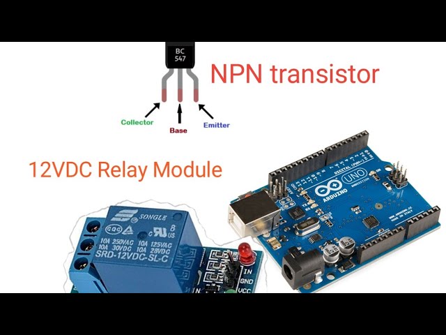
buy any generic 12V LED strip that you like. Buy a 12 V Relay module , connect it to an ardino and done
you can control the LED strip with arduino
(The LED strip WILL require a 12V power supply)
here is a 12V 5m LED strip as an example
you can probably fit a relay module and a 12v power supply in your budget
 regal mortar
Ohk thanks I get the outline of the idea but I don't have much experience in Arduino so how do I connect the relay is there any videos regarding that can guide me?
 quaint nacelle
regal mortar
Ohk thanks I get the outline of the idea but I don't have much experience in Ard...
quaint nacelle
regal mortar
Ohk thanks I get the outline of the idea but I don't have much experience in Ard...
Here's a video that I just skimmed that seems plausible https://www.youtube.com/watch?v=VFzeFEPreC8
 regal mortar
Thankss
 reef ember
I just realized how bad the nintendo switch 2 is I want to get a handheld so I will most likely buy a steam deck of make my own
if I where to make my own hand held what micro controller should I use
quaint nacelle
How 'own' do you want it to be? A lot of people build projects like that around the guts of what are basically Android phones, and that can save a lot of steps if it's suitable. Custom stuff might be more fun to build of course.
reef ember
quaint nacelle
How 'own' do you want it to be? A lot of people build projects like that around ...
I want a handheld that can run stuff like videos and play 1080p low settings. I have a idea of making it so I can add joycons or a external mouse and keyboard or I could add a controller. I have a 3D printer so it would be pretty easy to make the shell but I basically need something with a lot of ports
elfin sphinx
reef ember
I want a handheld that can run stuff like videos and play 1080p low settings. I ...
A steam deck is a pretty powerful device, it's basically a pc. If u were to make your own, you can choose a board from the lattepamda alpha series, depending on how much performance you want. There is a youtuber called greatscott who has done this exact thing that u r talking about, u can check him out if u want
fast wagon
if i'm using wsl is there any way to permanently bind a port to wsl so that if it detaches or i take the usb out, it will still be connected to wsl when it reattaches
this is what claude said i should do, just want to make sure this is alright cause blindly following llms is probably not a good idea
run this in powershell:
$deviceId = "(Arduino device ID from usbipd list)"

usbipd bind --busid $deviceId --auto-attach```

run this in ubuntu (command prompt with wsl distribution)
SUBSYSTEM=="tty", ATTRS{idVendor}=="2341", ATTRS{idProduct}=="0043", SYMLINK+="arduino", MODE="0666"```
quaint nacelle
fast wagon
this is what claude said i should do, just want to make sure this is alright cau...
Hmm, looking at this, it seems like you'd want also --wsl? https://learn.microsoft.com/en-us/windows/wsl/connect-usb
fast wagon
quaint nacelle
Hmm, looking at this, it seems like you'd want also `--wsl`? https://learn.micro...
oh yeah
i rely too much on claude for system configurations lol
quaint nacelle
It's usually really helpful for at least pointing you in the right direction though
fast wagon
--auto-attach wasn't working so i told it that and then it gave me a solution that worked
fast wagon
quaint nacelle
It's usually really helpful for at least pointing you in the right direction tho...
yeah true
but if i'm completely relying on it the way i just did then what's the difference between me and a vibe coder lol
fast wagon
quaint nacelle
It's usually really helpful for at least pointing you in the right direction tho...
since this was the only issue i had no matter which ide i used, i decided to go back to platformio and deleted arduino ide
just want to make sure, just directly doing sudo rm -rf arduino-ide_2.3.5_Linux_64bit.AppImage is fine right
or is there any other uninstallation process
i probably should have asked this before doing it
quaint nacelle
Yeah I believe for AppImage stuff you can just remove the file and you're done
 cloud hinge
For pydroid is there a way to interface pydroid with pybluez to attach mac address or something similar to connect from android pydroid to esp32 with pyserial. I would like to use pygame to connect to all this and be able to recieve esp32 data into pygame. If we could get it to work then I think pygame on pydroid would be an excellent way to interface with esp32. I guess with a wire it's possible but wireless would be idea
 spiral sandal
cloud hinge
For pydroid is there a way to interface pydroid with pybluez to attach mac addre...
spiral sandal
cloud hinge
For pydroid is there a way to interface pydroid with pybluez to attach mac addre...
with wifi i guess telemetrix would work
old android don't expose serial it is quite recent
and bluetooth would need an api in pydroid i guess
cloud hinge
spiral sandal
with wifi i guess telemetrix would work
Nice, that's a good work around. Bluetooth is champ in less delay and super easy to work with pygame. I'll have to look into how pygame can be used with wifi. Great idea and I'll look into it. Much apprecieted!
cloud hinge
spiral sandal
old android don't expose serial it is quite recent
Good to know
spiral sandal
lot of serial port require drivers that are only in newer linux kernels
and vendors may not ship them on device
hid usually work but it is low speed
cloud hinge
Bluetooth also has only a 5 to 20 nano second delay. To be able to do all that on the android pygame would be priceless
spiral sandal
telemetrix works with pygbag/webview too ( so pygame-ce )
but wifi has more latency
cloud hinge
spiral sandal
i use https://github.com/ArminJo/Arduino-BlueDisplay and/or https://github.com/M...
I'll probably try this out, thanks for the links. Telematrix looks a bit complicated but maybe i can figure it out. Edit update. I may have found a way to use bt another way with pydroid3, if I do would u be interested? It looks pretty straight forward and I'll try and test later
spiral sandal
if same code can work in a webview+bt api yeah that would be really great
 lyric vigil
will bluetooth keep working even if you lightsleep()
esp32
elfin sphinx
lyric vigil
will bluetooth keep working even if you lightsleep()
esp32
no
te only things active during light sleep are RTC , ULP coprocessor
lyric vigil
elfin sphinx
no
te only things active during light sleep are RTC , ULP coprocessor
what about after wakeup?
elfin sphinx
lyric vigil
what about after wakeup?
after proper wake up , the ESP32 will behave normal meaning all the stuff will be active
although youy might need to "reconnect" to the device you were previously connected to
lyric vigil
i think ill test it
elfin sphinx
lyric vigil
i think ill test it
you should read up the documentation about power saving modes to understand all the details
lyric vigil
noted, thank you
 solemn robin
Hellow
 pseudo sinew
reef ember
I want a handheld that can run stuff like videos and play 1080p low settings. I ...
pseudo sinew
reef ember
I want a handheld that can run stuff like videos and play 1080p low settings. I ...
You can get a Mini Desktop/PC. You can power it off of a Portable Battery if you get one that only needs like 65 Watts of Power. Then the rest is getting a small screen and hook everything up and you should be good to go. Mini PCs costs a lot cheaper than steam decks or handhelds computers. I kinda built a mini PC gauntlet thingy like in the Sci-Fi movies which looks cool and runs Linux. You'll be surprised by how much Windows eats up your battery and/or how much Linux saves your battery. Then if you want to add pins to your mini desktop to make it like a Raspberry Pi, just plug in an ESP32 and you are good to go.
elfin sphinx
pseudo sinew
You can get a Mini Desktop/PC. You can power it off of a Portable Battery if you...
How is this handheld lol
pseudo sinew
elfin sphinx
How is this handheld lol
You can make it handheld. Might not be that light but not that heavy either depending on how you go about to make it.
elfin sphinx
pseudo sinew
You can make it handheld. Might not be that light but not that heavy either depe...
what you are describing is just a laptop. A full computer powered by battery and got a display xd.
laptops arent exactly "handheld".
and the cost / trouble of making them handheld is just too much compared to buying a ready board like lattepanda
or just buy a small laptop and call it a day
pseudo sinew
elfin sphinx
what you are describing is just a laptop. A full computer powered by battery and...
Laptops are BIGGER and also needs more power than Mini PCs. At least the ones I looked at. Have you never seen a mini gaming PC before? Also, a lot of Laptops can't be upgraded or they are just too big. Mini PCs are small and can be upgraded as well as running on lower power and are just as strong if not stronger. Laptops aren't exactly handheld, hence the name "laptops", implying on the lap. But Mini PCs can be made to be held if you know what you are doing. I made one on my arm/wrist like in the Sci-Fi movies. Of course, I used a smaller keyboard for it and a touchpad mouse.
The cost of LattePanda is too much. I recommend looking on Amazon for Mini PCs and then you'll find that Mini PCs are a lot cheaper than LattePandas.
elfin sphinx
pseudo sinew
Laptops are BIGGER and also needs more power than Mini PCs. At least the ones I ...
I think your definition of handheld is that " can be held in hand regardless of if it is comfortable or not". My definition of handheld is " like a steamdeck/game console, should be comfortable ". And the laptop was clearly a sarcastic comment.
if you have good mini PC recommendations , feel free to send links. i am not totally opposed to the idea of it , but all i have seen are either bulky or expensive for a handheld
pseudo sinew
elfin sphinx
I think your definition of handheld is that " can be held in hand regardless of ...
My definition of a handheld is something that can be held on the hand. Tablets are considered handheld in my definition. They are okay to be held on the hand.
You didn't bother to check for yourself on Amazon so I did your job for you. The first few mini desktop computers on Amazon were small and cheap(Under 500 USD and VS their Laptop versions).
https://www.amazon.com/Micro-Mini-PC-Computers-N5105/dp/B09Q8Z6VB7
https://www.amazon.com/Desktop-Pentium-Display-Compact-Education/dp/B0DZP66CR8
https://www.amazon.com/KAMRUI-Windows-Desktop-Computer-Ethernet/dp/B099KSJN8P
There are more expensive ones with better specs and more power.
https://www.amazon.com/GMKtec-4-90Ghz-Desktop-Computer-Windows/dp/B0DCVTQ9CL
https://www.amazon.com/KAMRUI-Processor-Windows-Computer-Business/dp/B0C1M822S2
https://www.amazon.com/Beelink-SER5-Graphics-Computer-Support/dp/B0C2P486GQ/
For the price range, they beat Steam Decks. Steam Decks are not worth it in my opinion. They are weaker and can't run Windows well, if at all. These Mini PCs can run Windows very well. Although the one I have I ran Linux on it since it uses less power. Also it's literally on my arm, and pretty comfortable. You never seen a Sci-Fi device like in the movies where they have something strapped on their arm and some computer stuff they tap on???
To make it even better, you can upgrade your mini-PC specs unlike Steam Decks.
elfin sphinx
pseudo sinew
My definition of a handheld is something that can be held on the hand. Tablets a...
500 USD is cheap ? 😂
he just wants something that can play some 1080p videos and games , he aint trynna create steamdeck lol.
if steamdeck is worth it or not , is your opinion which is pretty irrelevent to the question OP is asking.
i did do my research and as i said in my previous message, they are either bulky or expensive for a handheld device that needs to play some video and some games.
also with your definiton of "handheld" , even small laptops are handheld since they can be held on your hand.
you have to understand that OP wants to make it handheld , which means it needs to have a battery (and in turn means that the actual device needs to consume little power) , a display . Good luck fitting all that in a "handheld" space.
is it possible to fit all that with the mini PC you mentioned ?maybe. will it be handheld after all that ? i highly doubt it.
the sheer thickness of these things is crazy
really not sure where you are getting the idea of competeing against a steamdeck
 vernal schooner
Hello anyone can help with pic microcontroller but assembly code? I need help with a debug. Thanks
Do I post my question on stackoverflow nd send here?
indigo plover
vernal schooner
Hello anyone can help with pic microcontroller but assembly code? I need help wi...
What's the question and which PIC is it?
 autumn stratus
Hey Guys,
I'm new here and wanted help with a project im working on. I have a custom i2c PCA which houses 9 vl53l3cx, time of flight sensors and a tca9548a. I needed some help with my code.
The problem im having is that the readings from my sensors are very inconsistent.
Here's the code im running
 hasty zealotBOT
autumn stratus
Here's the code im running
hasty zealotBOT
autumn stratus
Here's the code im running
Click here to see this code in our pastebin.
 mental jungle
what books do you recommend that teach how to apply electronics concepts into practice? I've done a foundation year (prerequisite year before going into a degree course if you do not have the necessary A level/GPA grades to get in) so I know the basics already but they barely taught how to apply it
indigo plover
mental jungle
what books do you recommend that teach how to apply electronics concepts into pr...
Define the "basics" you speak of. We'll move from there
 fresh jungle
Anyone know where to find the mediatek vcom usb drivers? Every site i go to is a roulette on whether or not I get malware and not even chatgpt knows what to put its money on
quaint nacelle
It sounds like this is for connecting an Android device to Windows?
I mean there's, wow: https://github.com/muojie/spec_mtk/tree/master/MTK_driver/Tool/Driver - USB VCOM Driver (binary)/Win7
GitHub
spec for mtk. Contribute to muojie/spec_mtk development by creating an account on GitHub.
GitHub
Gemini PDA Notes. Contribute to evadne/gemini-notes development by creating an account on GitHub.
Yeah this is a sketchy bunch of hits, you're right. This must come with some SDK with a wildly different name maybe?
Some of these hits are obvious malware sites, yikes.
elfin sphinx
mental jungle
what books do you recommend that teach how to apply electronics concepts into pr...
you learn practical stuff by doing practical stuff , not by reading books
mental jungle
I know that. I’ve already got a few simple projects that I want to make. Just want some books thatll help me better understand how to apply the theory into practice. For now, Ill be using a simulator (tinkercad) to construct my projects but even if I can buy a physical kit, I want to make sure I do things correctly so I dont end up damaging my components.
indigo plover
mental jungle
I know that. I’ve already got a few simple projects that I want to make. Just wa...
You mentioned basics. To me, the basics include the Laplace transform. Depending on your current knowledge, I'll provide a book reference, either specialised or general
mental jungle
Then I guess Ive got more 'basics' to learn. I am in uni atm but Ill be starting my 1st year next year (sept2025). The foundation year only taught us the more elementary basics (e.g. rectification, smoothing capacitors, sensor basics). Currently, just doing notes for the rest of semester 2 before I go onto applying the knowledge
vernal schooner
indigo plover
What's the question and which PIC is it?
Got the question solved but still thanks
indigo plover
mental jungle
Then I guess Ive got more 'basics' to learn. I am in uni atm but Ill be starting...
Have you done op-amps? Transistors? Have you seen decoupling? Logic circuits?
mental jungle
indigo plover
Have you done op-amps? Transistors? Have you seen decoupling? Logic circuits?
Done op amps but not logic circuits. Assuming youre not from the UK, when you take a foundation year in university, it only teaches the bare basics you need to be able to understand the content when you get on to the actual degree. A foundation year assumes students do not have the necessary knowledge required to be on the course; in this case, because I’ve always done a biology based degree but I’ve switched to doing an engineering degree, I need to do a foundation year that teaches the basics (i.e. high school - entry level uni) of mathematics, mechanics and electronics. Hope that clears that up
indigo plover
mental jungle
Done op amps but not logic circuits. Assuming youre not from the UK, when you ta...
You could try your hand at making an amplifier and a small synthesiser to experiment with. It's a lot of fun and makes for good practical experience.
This book is good at starting you off : https://www.amazon.ca/Make-Analog-Synthesizers-Electronic-Synth-DIY/dp/1449345220

Make: Analog Synthesizers: Make Electronic Sounds the Synth-DIY Way
With your level, this is as much as I could recommend. There is a good challenge in here and it is a big learning opportunity
fresh jungle
quaint nacelle
Yeah this is a sketchy bunch of hits, you're right. This must come with some SDK...
Thats what im saying, if i manage to find it tomorrow imma see if I can get permission to put it on github to help the next poor soul who has to dig for it. Chatgpts word is it comes with SP flash tools but that one has about 10 clone sites with little indication of which one is the right one
The original "trusted source" redirects to a site with seemingly no download link save for those start now buttons that are conveniently placed ads
fresh jungle
Think i found it, will verify tomorrow
mental jungle
indigo plover
You could try your hand at making an amplifier and a small synthesiser to experi...
Thank you. Ive been reading art of electronics as so many people have been recommending it. It doesnt seem as complicated as other people say it is but then again my maths ability is pretty strong which helps
fresh jungle
Verified, it works
However i made an oopsie in my next to zero experience with low level programming in command line tools and failed to realize that the e in the command i ran was a prefix for erase
The metadata partition is now gone
quaint nacelle
Anybody ever written anything for a Cortex-M0? They seem to be everywhere now.
Just curious how 'fun' of a language you used, if it wasn't C etc.
indigo plover
quaint nacelle
Just curious how 'fun' of a language you used, if it wasn't C etc.
By "fun", is implied which company makes the part. The experience can be great; it can be tedious
 bitter swallow
I'll be using ESP8266, I want to know if it's codeable through python, and has a wifi module? I want to make a web interface along with it
elfin sphinx
bitter swallow
I'll be using ESP8266, I want to know if it's codeable through python, and has a...
it does have wifi capabilities.
It doesnt s upport the regular python though.
it supports micropython , which is a python based langauge meant for microcontrollers
quaint nacelle
If I'm interested in CPU architectures that aren't register or stack machines (e.g. dataflow), what's the right Discord to be in?
indigo plover
quaint nacelle
If I'm interested in CPU architectures that aren't register or stack machines (e...
Such a discord does not exist publicly
cloud hinge
Anyone use bluetooth pan ? https://github.com/SalimTerryLi/esp32_btstack_panu_example I find this discussion very interesting on different types of networking with pan bnep with ip adresses but I guess it might be mainly compatable with esp ide . I'm curious why I dont here about it more in the esp32 world. My main interest is bt tcp for ip adress networking
GitHub
A working example for esp32 bluetooth tethering on ESP-IDF framework with BTStack - SalimTerryLi/esp32_btstack_panu_example
 hallow igloo
elfin sphinx
it does have wifi capabilities.
It doesnt s upport the regular python though. ...
hallow igloo
elfin sphinx
it does have wifi capabilities.
It doesnt s upport the regular python though. ...
Yo saul
How are you bro?
 errant wigeon
hallow igloo
How are you bro?
errant wigeon
hallow igloo
How are you bro?
Please stick to the channel topics.
mental jungle
is there any software or website than can help verify if my circuit calculations are correct or is it a case of trial and error? I am using tikercad atm to simulate all my circuits (once I get a bit of additional income, ill buy the physical components)
indigo plover
mental jungle
is there any software or website than can help verify if my circuit calculations...
Falstad
Ltspice
Search for "electronic circuit simulation"
mental jungle
im fucking struggling in applying the thoery into practice. Ive used breadboard in my foundation year but tbh i learnt nothing. literally it was just do this and do that. Im trying to follow a basic circuit and struggling to assemble that
 glacial stone
i feel ya, learning electronics is hard for me, everybody be like "ohm's law ez"
but need a more intuitive understanding
mental jungle
also I dont just want to be following a tutorial, I want to learn why each component contributes to the circuit. Ill follow a few tutoorials on tinkercad so I can learn how to actually use the breadborad and start off from there.
 willow star
mental jungle
im fucking struggling in applying the thoery into practice. Ive used breadboard ...
willow star
mental jungle
im fucking struggling in applying the thoery into practice. Ive used breadboard ...
https://www.build-electronic-circuits.com/basic-electronics/
This website has helped me quite a lot when I was starting out, I feel like it explained stuff pretty well. It's probably good to refresh the basics if they weren't taught well
hallow igloo
errant wigeon
Please stick to the channel topics.
Ok sir
 ruby osprey
Hey, anyone know any P N junction transistor which flow charge when a small 🤏 current incounter? Why? I have a unusable phone so I make a app which turn the flash light 💡 of phone on voice command and connect two ✌ wires on flash light of phone , which just work like a switch to turn on any big Ac appliance, if found any transistor which can work like switch give little take more 👍
indigo plover
ruby osprey
Hey, anyone know any P N junction transistor which flow charge when a small 🤏 c...
Physics works in mysterious yet well understood ways. It's a bit like English in that regard
spiral sandal
ruby osprey
Hey, anyone know any P N junction transistor which flow charge when a small 🤏 c...
don't use wires keep complete electric separation , use a LDR instead of potentiometer in the classic triac AC voltage regulator in front of the flashlight
indigo plover
spiral sandal
don't use wires keep complete electric separation , use a LDR instead of potenti...
You understand his question??
spiral sandal
i guess he want to power on/off something with potientally dangerous AC feedback with a phone light
indigo plover
I see. My guess was that he wanted a bigger transistor, but got sidetracked asking how transistor amplification works
spiral sandal
when i hear "big ac" i raise my optocoupler
a LDR in that will do for dirt cheap

search for "ac dimmer"
indigo plover
Bro if he's asking for basic information about "big AC", do you think it wise to give him partial information? 💀
spiral sandal
we'll see, but yeah of course put everything in a locked box and keep indoor ( but kinda obvious with the phone )
indigo plover
Is it obvious? Because it seems to me 1) extrapolation of meaning is done on that gibberish we are reading, 2) if he's asking questions about medium voltage applications, he really ought to not play with it
 stoic pewter
does someone know if you can use assembly on a arduino nano?
 willow kernel
(I recommended he ask here, so if not a great place to ask, blame the Hemlock)
quaint nacelle
an Arduino Nano is an ATmega328 chip, so you just need an assembler for that.
AVR-GCC is the toolchain I think people mostly use?
 modern wigeon
I didn't know Python could be utilized for microcontrollers, I thought that was a domain for C++.
 nimble badger
modern wigeon
I didn't know Python could be utilized for microcontrollers, I thought that was ...
nimble badger
modern wigeon
I didn't know Python could be utilized for microcontrollers, I thought that was ...
It actually can be even better than C++ but Python is smoother while C++ is faster which means you have to first figure out what you wanna code needs to be fast or smooth and precise in the case of microcontrollers
elfin sphinx
nimble badger
It actually can be even better than C++ but Python is smoother while C++ is fast...
what does "smoother" even mean
elfin sphinx
modern wigeon
I didn't know Python could be utilized for microcontrollers, I thought that was ...
you can even write rust for it , javascript for some high end microcontrollers , there are tons of languages that you can use with microcontrollers.
nimble badger
elfin sphinx
what does "smoother" even mean
dynamically, it runs the code smoother, esp when it comes to robotic arms. Python is super efficient in that case
nimble badger
elfin sphinx
you can even write rust for it , javascript for some high end microcontrollers ,...
there is tons of languages to be used but it optimally depends on the application for which you wanna use the microcontroller for
has anyone worked with ROS ?
elfin sphinx
nimble badger
dynamically, it runs the code smoother, esp when it comes to robotic arms. Pytho...
how is "dynamically " getting translated to "smoother" ? ? i dont understand
"python is super efficient" in terms of what ?? using resources ? speed ?
you said "python is smoother" , and then you said "smoother means dynamic" , so are you trying to say "python is smoother dynamically" ?? makes no sense to me
and if you say that "python code makes the movement of robot arms smoother" , then that has no meaning because you should be able to do everything in C++ as well.
the things taht cause movements to be not smoother is code. if you write bad code , teh movement will not smooth , regardless of if code is python or c++.
dynamically typed languages take up more resources than compiled ones. and resources is the one thing that we dont have much of when it comes to microcontrollers.
"it runs the code smoother" , dont even know what that means
nimble badger
elfin sphinx
"it runs the code smoother" , dont even know what that means
you might have to google its definition then xd take it easy man! we're not in a word battle! we're here to learn so I hope you didn't take it personally!
 elfin sphinx
nimble badger
you might have to google its definition then xd take it easy man! we're not ...
elfin sphinx
nimble badger
you might have to google its definition then xd take it easy man! we're not ...
i still dont see the word smooth defined anywhere : )
efficiency is a totally different term
and in fact C++ is more efficeint when it comes to using resources than python (efficient as in , it uses less resources in the end)
im not trying to battle or anything , im just trying to understand your point of view as i didnt understand what you were trying to say
you were saying things like "you need to figure out if you want your code to be fast or smooth and precise" and from what i can see , C++ can do all 3. Its fast, "smooth" (or efficient as you are trying to imply) and "precise"(dont even know what you implied by taht , but whatever) 🤷♂️
elfin sphinx
nimble badger
thats just a random definition you pulled out , dont know how this relates to our convo
nimble badger
of course C++ is as great as Python! i'm working with C++ now
elfin sphinx
again , just generic talk is not helping : )
nimble badger
👍
cloud hinge
modern wigeon
I didn't know Python could be utilized for microcontrollers, I thought that was ...
I use python in conjunction with micro controllers to control them and it seem like a win win situation having the best of both worlds
cloud hinge
elfin sphinx
you can even write rust for it , javascript for some high end microcontrollers ,...
What micro controllers allow java to written on them? that sounds interesting
elfin sphinx
cloud hinge
What micro controllers allow java to written on them? that sounds interesting
one that i know which uses javascript is ESP chip , not sure which exactly , but i have heard you can use js on esp chips
cloud hinge
elfin sphinx
one that i know which uses javascript is ESP chip , not sure which exactly , but...
Awesome, thanks for the info. Found this site for it https://www.espruino.com/ looks like it's lightweight java witch is super interesting but I dont know much about java yet
 verbal marsh
i'm thinking of learning some electronics by working on a project and i've chosen the raspberry pico W for the microcontroller. it seems that some components use 5V for its logic level so it may not work for the pico which uses 3.3V. i'm wondering, is this a huge issue in buying the components for my project? it's a simple alarm clock and i'll need an LCD screen, RTC, buzzer and some buttons for instance, should I also look into getting components to convert 5V to 3.3V?
elfin sphinx
verbal marsh
i'm thinking of learning some electronics by working on a project and i've chose...
you need a logic level shifter yes.
usually a lot of modules if they support 5V logic level , there is a very high chance they support 3.3V as well. you should check the datasheet of the module to confirm.
but if you do somehow end up in a situation where u have to interface a module that only works on 5V logic level with pico , you can buy a logic level shifter module like this one , its very cheap and it can convert both 5V to 3.3V as well as 3.3V to 5V https://learn.sparkfun.com/tutorials/bi-directional-logic-level-converter-hookup-guide/all
i wouldnt worry too much about it during component selection. and i would buy a bunch of those logic level shifters just to have on hand , they are pretty cheap , you can get like 3-4 of them (4 channels each) for like 1 USD
verbal marsh
ohh, gotcha. thanks for the tutorial link
fast wagon
is it possible to store files on an arduino r4 minima
i'm not able to find anything only specific to this model
like just as an example, if i were to try storing a text file in the arduino
indigo plover
fast wagon
is it possible to store files on an arduino r4 minima
Technically, yes
You would have to roll your own file system or port an existing one
Unless someone is kind enough to maintain one for you
fast wagon
indigo plover
You would have to roll your own file system or port an existing one
i see
so it's not as simple as just creating the file with fstream and then pushing that to the board
indigo plover
fast wagon
so it's not as simple as just creating the file with fstream and then pushing th...
Nope
#embed will change that up a bit, but you'll have to use C... unless it is enabled as an extension for whichever C++ compiler you use
 tawny zephyr
fast wagon
indigo plover
`#embed` will change that up a bit, but you'll have to use C... unless it is ena...
tawny zephyr
fast wagon
indigo plover
`#embed` will change that up a bit, but you'll have to use C... unless it is ena...
oh yeah my bad i should have specified, this is with using C
indigo plover
fast wagon
oh yeah my bad i should have specified, this is with using C
Then you may be in luck
 alpine dew
Yo im planning on buying a Raspberry pi pico to turn into a rubby ducky usb and troll my friends any ideas on what I should make it do NO I WILL NOT MAKE IT DELETE THEIR SYSTEM32
 near drift
I seem to have fried my esp32 and i'm not sure how
The pwr led will not illuminate anymore
I don't think i was doing anything to short it. Had my led matrix plugged into the gpio pins as before and was trying to flash some new code onto it
Had done this routine dozens of times before. Not sure what heppened
It doesn't look damaged or anything and no smoke
 drifting bluff
alpine dew
Yo im planning on buying a Raspberry pi pico to turn into a rubby ducky usb and ...
drifting bluff
alpine dew
Yo im planning on buying a Raspberry pi pico to turn into a rubby ducky usb and ...
i am new to python clearly i have much to learn what is a rubber ducky usb and like what do you mean turn into ahh migrainsnjnjs
alpine dew
Ok so a rubber ducky is a USB that can autorun pre-coded payloads and it emulates an HID to trick the pc they are pretty cool
@drifting bluff
drifting bluff
alpine dew
Ok so a rubber ducky is a USB that can autorun pre-coded payloads and it emulate...
cant that be used mali-- nvm
alpine dew
drifting bluff
cant that be used mali-- nvm
Yeah it's very common but they can also be used for harmless pranks
drifting bluff
alpine dew
Yeah it's very common but they can also be used for harmless pranks
oh, like what
alpine dew
drifting bluff
oh, like what
Making a rickroll play with no traces idk tbh I havent explored it enough yet
drifting bluff
wait how do you turn a microcontroller into a usb, a usb flash drive?
alpine dew
drifting bluff
wait how do you turn a microcontroller into a usb, a usb flash drive?
A microcontroller cant be a USB and a USB cant be a microcontroller they are very different things
drifting bluff
alpine dew
A microcontroller cant be a USB and a USB cant be a microcontroller they are ver...
do you have a little youtube vid or site about this stuff because idk anything abt this clearly how do you get a usb to force run code with a quick plug in it seems somewhat possible but with only a rasp pi tho it then seems somewhat impossible
alpine dew
drifting bluff
do you have a little youtube vid or site about this stuff because idk anything a...
There's applications online but they are not the most reliable I am going to bed now anymore questions can be left here for another member to answer or directed to my DMs and I can answer them in the morning
 leaden bramble
alpine dew
A microcontroller cant be a USB and a USB cant be a microcontroller they are ver...
leaden bramble
alpine dew
A microcontroller cant be a USB and a USB cant be a microcontroller they are ver...
not exactly true
you can emulate a storage device with stuff like tinyusb
and the other way around because of stuff like https://hackmag.com/security/rubber-ducky/

HackMag
Tech magazine for cybersecurity specialists
quaint nacelle
and on the extreme end of that there's stuff like https://www.embedded.com/soft-peripherals/ where ALL of the I/O is software
(I use some music players that have this chip in them)
At 250MHz, the IP3023 can emulate most serial or parallel interfaces out there. In addition to 100Mbps Ethernet, 802.11g WiFi, Utopia, Bluetooth, and HomePlug are all within its grasp. Each is implemented as a software state machine that makes greater or lesser demands on the processor, depending on its complexity and speed. A PCI interface, for example, is a 200-instruction loop that takes up about one-tenth of the processor's horsepower.
``` bizarrebut I guess if you're a DSP programmer at heart and want to approach other problems the same way, well Ubicom has your jam
drifting bluff
oooo
drifting bluff
quaint nacelle
but I guess if you're a DSP programmer at heart and want to approach other probl...
whats a dsp programmer im new here
quaint nacelle
DSPs are "Digital Signal Processors".. Ken Thompson of UNIX/UTF-8/Go fame believes they are the worst thing to program for in the world.
drifting bluff
where in the world do i learn this ducky language
quaint nacelle
It's basically like only having math as your coding tool I guess? I can't claim to "be" one (yet?)
Lemme find an example
drifting bluff
quaint nacelle
DSPs are "Digital Signal Processors".. Ken Thompson of UNIX/UTF-8/Go fame believ...
oh i knew that but not the acronym
quaint nacelle
Like, bonkers levels of depth/alien-ness https://ccrma.stanford.edu/~jos/pasp/
PHYSICAL AUDIO SIGNAL PROCESSING
FOR VIRTUAL MUSICAL INSTRUMENTS AND AUDIO EFFECTS
drifting bluff
ok but like how do i learn the ducky language
quaint nacelle
drifting bluff
quaint nacelle
It's basically like only having math as your coding tool I guess? I can't claim ...
yet????
quaint nacelle
I mean, arguably I should eventually learn the assembly language for one of these beasts and try teaching it to do something
I feel like what Ken Thomspon was talking about is the fact that DSP instructions can be super complex mathematical functions, and it's hard for regular compilers to generate good code for them
So you end up having to write assembly every time
drifting bluff
quaint nacelle
I mean, arguably I should eventually learn the assembly language for one of thes...
where do you even learn assembly and why does it get no love
quaint nacelle
I guess this is what I should have linked https://www.analog.com/en/lp/001/beginners-guide-to-dsp.html
quaint nacelle
drifting bluff
where do you even learn assembly and why does it get no love
This guy's books are fantastic, there's even an ARM one now: https://www.amazon.com/Art-ARM-Assembly-Randall-Hyde/dp/1718502826/

Building on Randall Hyde’s iconic series, delves into programming 64-bit ARM CPUs—the powerhouses behind iPhones, Macs, Chromebooks, servers, and embedded systems.
Following a fast-paced introduction to the art of programming in assembly and the GNU Assembler (Gas) specifically, you’ll exp...
drifting bluff
but like where to learn ducky language
quaint nacelle
The cursed thing is that assembly is different for every hardware architecture
so ARM assembly looks not much like Intel/x86 assembly
But ARM is a fun one to learn currently, and the Randall Hyde books are lovely
My first language was 6502 assembly on the Commodore 64.
I mostly typed in game code I saw in magazines
and then I would try to change something without breaking it
I honestly don't remember much 6502 at this point, but it did teach me what was going on
drifting bluff
quaint nacelle
My first language was 6502 assembly on the Commodore 64.
commodore 64 is hype
but like ducky language
quaint nacelle
So.. which one do you mean by "ducky" then?
Sometimes it's actually really hard to find docs without paying some manufacturer money, which is irritating.
drifting bluff
i think its called ducky script
quaint nacelle
Ohhhh, you mean for this USB thing from above?

Getting Started with DuckyScript Payload development
My bad, this is nothing like assembly, more like BASIC or DOS batch language.
drifting bluff
ty
quaint nacelle
I thought "ducky" was brainrot for "low-level" or "machine" 
drifting bluff
wahhhhhhh???
elfin sphinx
drifting bluff
do you have a little youtube vid or site about this stuff because idk anything a...
google "pi pico rubber ducky" there should be countless videos on it
if you need a specific one , google a youtuber named "networkchuck" he has a video on it
 compact geyser
on a raspberry pi, it is better to use bluetoothctl as a subprocess or to use pybluez library . Python programming
?
fast wagon
quaint nacelle
DSPs are "Digital Signal Processors".. Ken Thompson of UNIX/UTF-8/Go fame believ...
why does he believe that lol
also i feel like there's not much attention towards lidar and radar sensors within the dsp community
this is the part of dsp i'm mainly into
lidar, radar, ultrasound, and any other sensors beneficial to drones and autonomous vehicles
indigo plover
fast wagon
also i feel like there's not much attention towards lidar and radar sensors with...
Imo, phased arrays aren't pleasant to design. Beamforming is still a hard engineering challenge. In the absence of accessible and useful CAD tools for beamforming, the community will keep this level of disinterest
fast wagon
indigo plover
Imo, phased arrays aren't pleasant to design. Beamforming is still a hard engine...
but the same principles are still needed right
indigo plover
fast wagon
but the same principles are still needed right
Which ones and where?
fast wagon
indigo plover
Which ones and where?
like the general principles of dsp
whatever is taught in a normal dsp textbook/class
glacial stone
sure, it's phase, time delay, and sensitivity to timing and data rate
and digital scales better in some use cases
glacial stone
quaint nacelle
DSPs are "Digital Signal Processors".. Ken Thompson of UNIX/UTF-8/Go fame believ...
i doubt that programming DSP is any harder than designing analog SP circuits..
indigo plover
fast wagon
whatever is taught in a normal dsp textbook/class
Okay I see what you mean. The answer is as such: the problem is not the signal processing or programming a DSP; the problem is engineering antennae and testing the phased array. The textbook will show you how to ride a bicycle; phased array are flying plane. On top of that, you hit the problem that beamforming and whatever modulation you use on top should follow FCC regulations. The moment Maxwell's equations become accessible to the layman is the moment you will see tutorials on beamforming
fast wagon
indigo plover
Okay I see what you mean. The answer is as such: the problem is not the signal p...
i see
so would it be best to not focus on classic dsp then?
or should i still learn dsp as usual but along with that
would ultrasound be classic dsp without the extra problems you mentioned?
indigo plover
fast wagon
would ultrasound be classic dsp without the extra problems you mentioned?
Yes. Although you would have to also do some wave physics. Air isn't a linear medium... at all. That's how you can produce a Doppler shift from mechanical waves simply colliding in mid-air. But yes, doing an ultrasonic phased array is a good start in this field. I recommend it
fast wagon
indigo plover
Yes. Although you would have to also do some wave physics. Air isn't a linear me...
and usually how would these be simulated
like if i was doing it on my own
probably gonna be a while before i can work on making my own sensors
quaint nacelle
This is hilariously long but I also haven't really seen a more-comprehensive start-to-finish CPU architecture walkthrough https://www.youtube.com/watch?v=jC_z1vL1OCI if anyone is interested.

HUGE shout out to Casey for coming on and helping me finally understand CPUs. ARM vs x86 is not as simple as we might like to believe...
CASEY'S STUFF
https://x.com/cmuratori
https://www.computerenhance.com/
Check out my Twitch, Twitter, Discord more at https://t3.gg
S/O Ph4se0n3 for the awesome edit 🙏
(I'm not normally a giant Casey fan but he's not ranting about anything in this)
indigo plover
fast wagon
and usually how would these be simulated
I'd say writing your own Python script for wave simulation is the way to go. There are lots of modules for that. Fortran is also really good for that, but not as modern. Start with a 2D array to begin with. Assume air is a linear medium and build your simulator in consequence
indigo plover
fast wagon
probably gonna be a while before i can work on making my own sensors
For what purpose would you need to make your own sensors?
fast wagon
indigo plover
For what purpose would you need to make your own sensors?
if i wanted to work on my own drone projects completely from scratch
indigo plover
fast wagon
if i wanted to work on my own drone projects completely from scratch
And which sensor are we talking about?
fast wagon
indigo plover
And which sensor are we talking about?
ultrasonic
though in the future i also want to be able to implement lidar and radar sensors too
my focus for drones is lidar, radar, ultrasound, and computer vision
indigo plover
fast wagon
ultrasonic
So you want to make ultrasonic transducers?
fast wagon
indigo plover
So you want to make ultrasonic transducers?
i have no clue what a transducer is
i think i should just focus on learning right now
i know far too little to be thinking about this stuff
fast wagon
indigo plover
So you want to make ultrasonic transducers?
seeing what it means, yeah that's probably what i'm thinking of
indigo plover
Well, have fun 😇
 halcyon dagger
How fast can the Raspberry Pi 4b read the GPIO pins as input using the RPi.GPIO library? I read that the pi3 cant do much more than 20kHz but I don't know about the pi4b.
I need to read 5 pins at 88kHz, should I use RPi.GPIO or a C library?
indigo plover
halcyon dagger
How fast can the Raspberry Pi 4b read the GPIO pins as input using the RPi.GPIO ...
https://datasheets.raspberrypi.com/bcm2711/bcm2711-peripherals.pdf
5.4.1. Operating Frequency
The maximum operating frequency of the General Purpose clocks is ~125MHz at 1.2V but this will be reduced if the GPIO
pins are heavily loaded or have a capacitive load.
This is for the Pi 4b
halcyon dagger
Thanks!
 winged hollow
@ashen holly mere mute hai unmute karo
@ashen holly bro i say yo can my mic unmute please
 limber field
see good ideas for GPIO magic @indigo plover
indigo plover
limber field
see good ideas for GPIO magic <@420632995788226573>
What kind of ideas do you have in mind?
limber field
Well tried to get , RPITX2 , to work all I can do is 250 Khz to 100 Mhz , if outside that range a lockup or glitchyness occurs @indigo plover
GitHub
Rpitx, but has better pifmrds. Contribute to KubaPro010/rpitx2 development by creating an account on GitHub.
indigo plover
limber field
Well tried to get , RPITX2 , to work all I can do is 250 Khz to 100 Mhz , if out...
That's pretty cool! What specific hardware do you use?
limber field
RPI3B+ , since its been gathering dust . I want to try and make a Tkinter control panel for it then use it as a clock / RF source for experiments @indigo plover
RPTIX2 , claims to do - 5 Khz to 1.5Ghz
indigo plover
limber field
RPTIX2 , claims to do - 5 Khz to 1.5Ghz
Yeah, I looked into it... I personally wouldn't use it. This thing is dishing out some solid EM pollution thanks to it's lack of a proper transmitter. The creator doesn't formally recommend its use. If you want to use this, an empty field is your best bet next to making a Faraday cage
Rpitx2 is a software made for educational on RF system. It has not been tested for compliance with regulations governing transmission of radio signals. You are responsible for using your Raspberry Pi legally.
It's a fun toy, but you'll get the FCC with police at your doorstep in no time
 safe summit
Waveshare Pico 1.8 + ESP32-C6-Pico
 safe summit
for the month :3
 near drift
valid
safe summit
I managed to get text to print to it but I have to save the code is not exactly pretty hopefully I can find a better way
sorry to everyones eyes
def main():
    lcd_display = lcd.LCD_1inch8(brightness=15)

    lcd_display.fill(lcd_display.BLACK)

    rows = range(4, 120, 8)
    cols = range(0, 160, 8)

    with open('1986-hacker-manifesto.txt', 'r') as fh:
        row = 0
        col = 0
        for line in fh:
            for char in line:
                if char == '\n':
                    row += 1
                    col = 0
                else:
                    lcd_display.text(char, cols[col], rows[row], lcd_display.WHITE)
                    lcd_display.show()
                    time.sleep(0.05)
                    col += 1
                if col == len(cols):
                    col = 0
            if row == len(rows):
                row = 0
                lcd_display.fill(lcd_display.BLACK)
                time.sleep(10)
Does lvgl work in mpython and python. Nice project!
spiral sandal
lvgl works on micropython, cpython, both native and webassembly
but since it is cffi beware of cpython garbage collection it is way more aggressive than micropython (mark and sweep)
 fast geyser
safe summit
fast geyser
safe summit
It's a Waveshare Pico LCD 1.8 + ESP32-C6-Pico
safe summit
just a note the ESP32-C6-Pico isn't super compatiable with this lcd hat and I wouldn't recommend using it for reasons mentioned here https://github.com/orgs/micropython/discussions/17413 they didn't quite clone the GPIO pins right getting a different board later ~
safe summit
so turns out it might be a MicroPython bug fun 🙃
drifting bluff
i got the microcircut python thingy on a raspberry pi pico what else do i need to do inorder to turn it into a payload injector? like the rubeer ducky
drifting bluff
like which github thingy has the thing that disguises the pico as a hid and the other ducky script converter
 elfin sphinx
near drift
elfin sphinx
near drift
nicee
what are you making ? weather station of sorts ?
or is that distance sensor ?
near drift
elfin sphinx
nicee
yeah it's a temp humidity sensor. I'm making an led matrix display to hang up on my wall
I fried my last esp32 during development of the code. Not sure what I did wrong. Ordered 2 more and had to spend couple bucks extra for free shipping so i bought the sensor
elfin sphinx
near drift
yeah it's a temp humidity sensor. I'm making an led matrix display to hang up on...
ooo noice
elfin sphinx
near drift
I fried my last esp32 during development of the code. Not sure what I did wrong....
xdd
they always get me with the "orders over X are eligible for free shipping " too
near drift
elfin sphinx
xdd
they always get me with the "orders over X are eligible for free shipping ...
it actually made sense though because the value of the sensor was more than the shipping would have cost. So it was basically free
safe summit
recenty made this waiting for more modules to fill it out ~

 timid hazel
 limber field
Its great you make videos @timid hazel
timid hazel
Thank you
 balmy lichen
how do u connect multiple 5v modules on a pico if it only has one vbus port capable of delivering 5v?
can u buy like power boards that connect to the vbus and provide several more ports?
 swift horizon
Hlo guys
elfin sphinx
balmy lichen
how do u connect multiple 5v modules on a pico if it only has one vbus port capa...
Usually you just connect them directly to the 5v source. If I am not wrong , on the pico , the vubs pin is directly connected to the vcc pin of the usb power supply, so as long as your usb power supply is capable enough , you can attach multiple 5v modules to the same pin .
balmy lichen
how do u read schematics?
it looks nothing like it


but apparently it is
heeeeeeelppppp
 drifting mesa
on the schematic:
- GP15 connects to resister R1 side 1
- resister R1 side 2 connects to LED1 side 1 (+, the longer lead)
- LED1 side 2 (-, the shorter lead) connects to ground
on the "image":
- GP15 conencts to one of the resister leads
- the other resister lead connects to the long lead (+) of the LED
- the shorter lead (-) of the LED connects to a wire
- the wire jumps around, connecting to a GND pin on the pico
remember: - on each half of the center of a breadboard, columns are connected together
- resistors do not have polarity - they cannot be "backwards"
drifting mesa
i'm referencing the schematic's numbers, but on a resistor, the side are equivalent
put an LED or several other types of components in backwards, and it might be damaged, but a resistor doesn't care
balmy lichen
is the schematic different to the second image?
drifting mesa
technically, yes, as the schematic doesn't use the pico's ground pin, but that's a minor detail. the circuitry is equivalent
balmy lichen
how do i even learn to read it?
i dont see any correlation between those two images
whats this type of stuff called?
on google searching up for electrical schematic guides brings up things of completely different format
bruh theres literally no resources for reading microcontroller schematics
elfin sphinx
balmy lichen
how do i even learn to read it?
usually you will be dealing with the schematics shown on the left hand side , you wont see "images of circuit" like on the right hand side
as to "how do i read it ? "
well the first thing is to know what all the symbols for electronic components are , and knowing basic about them
like knowing what the symbol of resistor is , knowing the fact that resistors have no polarity , meaning they can be connected in any orientation and that wont affect their working etc etc
after that , the schematics are pretty straightforward as thuri explained.
if you have specific schematics and you need help with them , feel free to ask here
i dont really know how else to "teach" someone how to do this without working through few schematics
balmy lichen
elfin sphinx
if you have specific schematics and you need help with them , feel free to ask h...
whats it mean when its green?
like here

whys it green
is it to do with the positive side of the breadboard or something
and if ur reading in schematics how do you know where to plug what?
elfin sphinx
balmy lichen
whats it mean when its green?
in this case i dont see any particular meaning other than green showing that the pin is being used. and red would probably mean the pin is not used / connected anywhere
but its not a "rule" , its probably the PCB design software's way of telling you that you ahve used this pin
elfin sphinx
balmy lichen
and if ur reading in schematics how do you know where to plug what?
because the schematic tells me where to plug what
in the above one, the schematic tells me that , i am supposed to connect one side of the resistor to GP15 pin and the other side of that resistor to the anode(+ terminal) of an LED. the other terminal of the LED is show to be connected to ground.
are you aware of what different symbols mean in a schematic ? like the symbol of a resistor , capacitor etc ?
thats a very important part of reading a schematic
balmy lichen
yeah i do
elfin sphinx
balmy lichen
yeah i do
then you should be good to go
try to read more schematics and ask wheere you are stuck
thats pretty much how you learn (or at least thats how i learnt it , i havent seen a cours for it or smth)
 mortal bronze
Can someone recommend me an application which can simulate microcontrollers and stuff
elfin sphinx
mortal bronze
Can someone recommend me an application which can simulate microcontrollers and ...

IoT and Embedded System Simulator: ESP32, STM32, Arduino, Raspberry Pi Pico, displays, sensors, motors and WiFi simulation.
mortal bronze
elfin sphinx
https://wokwi.com/
Thank you, Saul Goodman.
 near gulch
im working on a home automation project
and for that im searching for a very low power and cheap microcontroller to turn relays on/off when it receives a signal (via wifi or blutooth)
I was thinking to go with an esp32, especially because of the esp-now protocol
but im not sure which board to use
near gulch
near gulch
im working on a home automation project
and for that im searching for a very low...
so basically i want the microcontroller to be energy efficient and atleast 10 digital io pins
and a built in wirteless communication method (preferebly esp-now)
elfin sphinx
near gulch
im working on a home automation project
and for that im searching for a very low...
from wht i know about the ESP32 wroom module ( the default ESP32 board like the one u see in the embed of above link)
it has some sort of light sleep mode where it keeps the wifi connection on , and it consumes about 5 mA or so doing that
so thats probably the lowest power consumption that you will be able to get out of it with wifi
not sure if thats energy efficient enough for you though
wifi burns a signficant amount of power so its kinda hard to be energy efficient with it
unless you do like a "interval based checkup" where you periodically wake up esp32 from deep sleep and then check if there is some data queued up for it or smth like that
dont know about pi pico W
also pretty sure STM32 has some sort of low power , wireless enabled chip too
if you go for pure power comparison , then ESP8266 will be a good bet as it consumes less overall power ( about 100mA) as compared to ESP32(200+ mA) when using wifi
but again , its a little weaker and it has a lot of its pins bootstrapped ( their pin states cannot be guranteed when ESP boots up , so random relays may get activiated during ESP bootup)
near gulch
elfin sphinx
from wht i know about the ESP32 wroom module ( the default ESP32 board like the ...
oh i see
rn im using an esp32-s3-wroom-1
and it seemed overkill to use that because there are cheaper boards,
and because all im doing is just waiting for a signal and just turning 5-10 relays on/off
balmy lichen

whats the arrow besides the diode mean?
and also here there is a symbol for a junction that leads to a resistor into 3v3 and on the other side a switch that leads to ground. how does that work?

why does this just cut off?
 elfin sphinx
balmy lichen
whats the arrow besides the diode mean?
elfin sphinx
balmy lichen
whats the arrow besides the diode mean?
that is the symbol of LEDs
elfin sphinx
balmy lichen
and also here there is a symbol for a junction that leads to a resistor into 3v3...
you take a switch with 2 pins , to its one pin , you connect a 10k resistor and you connect the other side of that resistor 3.3V.
to the same pin of the swithc, you connect another 10k resister which connects to the GP13 pin
and finally , on the second side of switch , you connect it to ground
elfin sphinx
balmy lichen
why does this just cut off?
thats they symbol for the switch.
the schmatic uses switch with 4 terminals but makes use of only 2 so thats why the other 2 terminals are just green
balmy lichen
elfin sphinx
you take a switch with 2 pins , to its one pin , you connect a 10k resistor and ...
so if the junction connects to the switch and the resistor, what is the junction itself?
like i get how everything else is wired except for the junction
elfin sphinx
balmy lichen
so if the junction connects to the switch and the resistor, what is the junction...
Junction is just a point where lot of connections are made. It's not a physical thing like a switch. Like if you solder together 3 wires , the point where they are soldered is a junction
balmy lichen
so does that basically mean the button pin column has to be on the column of the resistor
does the junction just mean they are both in a spot that receives the same electrical power
like on the same terminal strip
elfin sphinx
balmy lichen
does the junction just mean they are both in a spot that receives the same elect...
Yes , pretty much.
balmy lichen
should i put the button over the center divider?
elfin sphinx
All the 3 parts that are connected to a junction go in the same column of the breadboard so they are connected together
elfin sphinx
balmy lichen
should i put the button over the center divider?
Think about it
How will the electric connections be formed
Also depends on what kind of button u r using
balmy lichen
it has four feet
two on each side
push button
so would putting the button on top of the center divider be required cuz there has to be opposite wiring
elfin sphinx
balmy lichen
so would putting the button on top of the center divider be required cuz there h...
well thats the point yes
if you are using a tactile switch like the one show in picture , the pins i circled will be the ones you would wire , and yes , you would need them to be on the different sides of divider . if you put both the pins in the same column in the same side of divider , they will just be shorted together which we DONT want

 paper pike
Is there a sensor for reading DNA?
indigo plover
paper pike
Is there a sensor for reading DNA?
Not really
paper pike
What's one possible way?
elfin sphinx
going to a lab and submitting blood sample so they can run the DNA test on their multimillion dollar machine
why do you want a DNA sesnor ?
indigo plover
paper pike
What's one possible way?
Yeah. Basically, you sensor bills you for a few thousand dollars every time you make a measurement and takes 4 weeks to produce the sequenced DNA
paper pike
elfin sphinx
going to a lab and submitting blood sample so they can run the DNA test on their...
Make a cheap affordable way to test if somebody has a specific genetic disorder and they can't go to the hospital because of that disorder
elfin sphinx
paper pike
Make a cheap affordable way to test if somebody has a specific genetic disorder ...
ok , so , there isnt any DNA sensor that you can just buy for few bucks and hook up to arduino , such thing doesnt exist
if it was possible to make such a complicated machine like that, it would have already been done by someone
You said you want to check if someone has a Specific genetic disorder
so what you should do is , go to a lab , see how they do the test , check what exactly they do ( im no chemsit but what they probably od is draw your blood and run various chemical tests on it and check their results ) . and find the test that they do for your genetic disorder
then , you should find some way to do all this with your device
hasty zealotBOT
 :ok_hand: applied timeout to @wild rose until <t:1749651851:f> (10 minutes) (reason: duplicates spam - sent 4 duplicate messages).
The <@&831776746206265384> have been alerted for review.
indigo plover
@paper pike here is the handheldest DNA sequencing device
https://nanoporetech.com/products/sequence/minion
Yes. It costs 5'000$

Oxford Nanopore Technologies
The only palm-sized, real-time devices for DNA and RNA sequencing
willow star
indigo plover
<@1318626588560199692> here is the handheldest DNA sequencing device
https://nan...
I'm actually very surprised at how cheap this is, I would assume a machine like this would cost hundreds of thousands of dollars minimum
indigo plover
willow star
I'm actually very surprised at how cheap this is, I would assume a machine like ...
Yes. The training is 7'000$. The base device is 3'000$. The flow cells are 200$ each
elfin sphinx
Although im sure it has its limitations in some way
 worn sparrow
willow star
I'm actually very surprised at how cheap this is, I would assume a machine like ...
worn sparrow
willow star
I'm actually very surprised at how cheap this is, I would assume a machine like ...
that's what i thought
indigo plover
That said, all that microfluidics research is paying off
 rocky sparrow
so I have a (rather old) previous laptop with a dead battery
would it be overkill to take out the mother board and use it as a glorified Raspberry pi?
elfin sphinx
rocky sparrow
so I have a (rather old) previous laptop with a dead battery
would it be overkil...
not really , its a good option
also why would you take out the motherboard ? just use it as is , it should still work perfectly fine.
rocky sparrow
fair
removing the keyboard and screen might be a bit of a pain though
since I'm planning on using it as part of a cosplay
though I am no where near building a human size Gundam
elfin sphinx
rocky sparrow
since I'm planning on using it as part of a cosplay
though I am no where near bu...
why do you want a full blown computer as a part of your cosplay ?
indigo plover
rocky sparrow
so I have a (rather old) previous laptop with a dead battery
would it be overkil...
How do you plan on using this motherboard to do IO?
rocky sparrow
elfin sphinx
why do you want a full blown computer as a part of your cosplay ?
lights and a few other features
rocky sparrow
indigo plover
How do you plan on using this motherboard to do IO?
plug in desktop peripherals, load script from USB then unplug everything
elfin sphinx
rocky sparrow
lights and a few other features
what "few other features" ?
because you usually woudl use a PC /raspberry pi when you need tons of heavy processing power for stuff like running a webserver or gameserver or stuff like that
if you need to light few LEDs, you should use arduino
rocky sparrow
no idea if this will actually happen but since I'm thinking of a WFM mech, (Probably Aerial) having the shield be a few drones that hover around me
elfin sphinx
rocky sparrow
no idea if this will actually happen but since I'm thinking of a WFM mech, (Prob...
.....no idea what you just said , what is a WFM mech ? and what is a shield be a few drones taht hover around you ?
rocky sparrow
a Gundam
one of the mechs has a shield that's also a few drones sometimes
elfin sphinx
a singular shield is a few drones ?
also what is a gundam
can u explain it like a person has no idea what u are talking about ?
and more importantly , what are you going to use the raspberry pi / pc for ?
safe summit
FYI none of this chat is on topic pis are not microcontrollers
elfin sphinx
safe summit
FYI none of this chat is on topic pis are not microcontrollers
pis can definately be discussed here
 safe summit
Oh my bad sorry
rocky sparrow
a giant robot
I just meant instead of buying more stuff using an old laptop
its 7 small drones that come together to form a shield
not quite sure if I want to go that far, might just buy an arduino to make the lights do what I want them to and leave the shield as one piece
indigo plover
rocky sparrow
a giant robot
I just meant instead of buying more stuff using an old laptop
its ...
By drone do you mean flying ones?
rocky sparrow
yes
rocky sparrow
its that big of a pain?
rocky sparrow
even if I just had it circle me in place?
indigo plover
Same difficulty
rocky sparrow
fair enough
indigo plover
This is a big engineering challenge. It's not impossible, but it's the kind of thing you need a team to work on or just be dedicated alone for years
The tech to make this easy does not exist yet
safe summit
I'm here for laptop voltron
 ebon pier
i wanna make my own ipad and computer and servers
like how would i make a server like a pc
near drift
ebon pier
like how would i make a server like a pc
i'm not really sure what you mean
elfin sphinx
ebon pier
like how would i make a server like a pc
a server is just a PC , so if you have a PC , you already have a server
 sturdy tulip
and "making a computer" is a very broad category with varying levels of DIY depending on what you actually want to do.
limber field
start simple Z80 or 6502 , get the concepts , look at 68000 CPU , look at pipelining structures
spiral sandal
or 8086 which is heavily documented, and run https://github.com/ghaerr/elks on it

GitHub
Embeddable Linux Kernel Subset - Linux for 8086. Contribute to ghaerr/elks development by creating an account on GitHub.
limber field
the beginings ...
 supple hinge
Hello , I need one developer write me PM
elfin sphinx
supple hinge
Hello , I need one developer write me PM
<@&831776746206265384>
indigo plover
supple hinge
Hello , I need one developer write me PM
To do what?
limber field
take over the world
ebon pier
elfin sphinx
a server is just a PC , so if you have a PC , you already have a server
Do you think if I mod a laptop the correct way I could use that maybe?
elfin sphinx
ebon pier
Do you think if I mod a laptop the correct way I could use that maybe?
what do you mean by "mod the correct way" ?
limber field
When modding - boxing gloves should not be worn @elfin sphinx
 mighty stratus
ebon pier
Do you think if I mod a laptop the correct way I could use that maybe?
mighty stratus
ebon pier
Do you think if I mod a laptop the correct way I could use that maybe?
You can use clouding services like AWS.
ebon pier
elfin sphinx
what do you mean by "mod the correct way" ?
Like get pc parts and other shit and solider and do the work and basically turn it into a pc/server or nah
spiral sandal
to assemble pc parts you only need a philips screwdriver, though sometimes it can lay on a isolated plane while testing
elfin sphinx
ebon pier
Like get pc parts and other shit and solider and do the work and basically turn ...
it already is a server , just load it with a server OS and you can treat your laptop/PC like a server
 oak quail
Hey.I would like to create my own server.I found out there are this things called NAS servers but they are soooo expensive. Could I perhaps be able to build myy custom "NAS server" using a raspberry pi? And if I do, I assume the connection to it would be made using the local network.Is there a way to connect to my server from another place?
I hope I addressed this matter in the good channel
elfin sphinx
oak quail
Hey.I would like to create my own server.I found out there are this things calle...
you can do that in multiple ways
first and most obvious would be to expose a port from your wifi router. This is pretty risky if you dont know what you are doing. you are essentially opening up a door from your house to the whole world.
next one would be setting up a VPN server alongside the NAS software on your raspberry pi . and use that to connect to your pi remotely . this will still require you opening up a port (afaik) but , it is a lot more secure as you can control who connects to the VPN
another one would be to route your NAS over something like cloudflare tunnels. This is alos fairly secure option to do it and doesnt require you to open any ports or anything like that
elfin sphinx
oak quail
I hope I addressed this matter in the good channel
well , i would say your question is pretty much totally irrelevent to this channel as this has pretty much nothing to do with python . but ill answer anyway 🤷
oak quail
well isn t raspberry pi python related?
Sorry I am not very experienced in this matter
elfin sphinx
oak quail
well isn t raspberry pi python related?
sure
if we go by that logic , even my pc has python installed. doesnt mean i can ask question abaout how to setup windows on it in a python channel ?
but as i said before , i have answered it anyways
elfin sphinx
oak quail
Sorry I am not very experienced in this matter
nah u r fine
oak quail
Ok thanks
 marsh iron
Can pygame work with raspberry pi
limber field
works on my RP3B+ , CPU does get hotter @marsh iron
marsh iron
Ok
 hexed bronze
I have arduino but i just know coding python. Can i code my arduino with python?
indigo plover
hexed bronze
I have arduino but i just know coding python. Can i code my arduino with python?

In this step-by-step tutorial, you'll discover how to use Arduino with Python to develop your own electronic projects. You'll learn how to set up circuits and write applications with the Firmata protocol. You'll control Arduino inputs and outputs and integrate the board with higher-level apps.
elfin sphinx
indigo plover
https://realpython.com/arduino-python/
(with this , you are not really writing code on the arduino . you are telling your PC how to control arduino , which are a little bit different . With pyfirmata ,you would need to have your arduino always attached to your computer when you want to run the code.)
if you want to write code for arduino , you will need C++
indigo plover
elfin sphinx
if you want to write code for arduino , you will need C++
We agree
ebon pier
elfin sphinx
it already is a server , just load it with a server OS and you can treat your la...
Kk
 trim condor
elfin sphinx
(with this , you are not really writing code on the arduino . you are telling y...
trim condor
elfin sphinx
(with this , you are not really writing code on the arduino . you are telling y...
so whenever i wanted to turn it on using python , it will requires the PC being attached to it ?
elfin sphinx
trim condor
so whenever i wanted to turn it on using python , it will requires the PC being ...
yes, to control the arduino wtih pyfirmata , you would need to have it connected to your PC always
but , if you write code for the actual arduino in C++ , you dont have to do that
trim condor
elfin sphinx
yes, to control the arduino wtih pyfirmata , you would need to have it connected...
i see , so it will make your life easier using C++ , but incase if i only know python its better to take Raspberry PI ?
elfin sphinx
trim condor
i see , so it will make your life easier using C++ , but incase if i only know p...
it depends on your project
if your project is going to be plugged into the PC when you want to run it anyways , its fine to use pyfirmata
but yea , C++ in general will allow you the most flexibility
and about the other question , rasppberry pi and arduino are not exactly replacement for each other , they both are different things serving different purposes.
raspberry pi is a small computer , its insanely more powerful than an arduino. like ,if an arduino is a bicycle , the rpi is a fighter jet.
Technically , yes , you could use rpi where you used arduino , but its very overkill
 warm birch
I have an esp32, Im okay at python, know a lil C but would be starting fresh with C++ should I be using micropython, or learn C++?
warm birch
elfin sphinx
(with this , you are not really writing code on the arduino . you are telling y...
is this also true for an esp32 with micropython?
elfin sphinx
warm birch
I have an esp32, Im okay at python, know a lil C but would be starting fresh wit...
if you want to learn more microcontrollers and learn more about hardware in general , C/C++ is always good to know well
elfin sphinx
warm birch
is this also true for an esp32 with micropython?
no
the micropython code actually lives on ESP32 and executes on it , you dont need to have it attached to computer
 gloomy granite
cool
 hollow quail
Not quite sure where to ask this but does anyone know how to emulate a VR controller input? And if so, what data would be required?
I currently have two devices with accelerometers and buttons that can be connected to a computer through python and data can be read from them
So ideally, there should be some way to translate this data into something that can be recognized by software as two VR controllers
spiral sandal
hollow quail
Not *quite* sure where to ask this but does anyone know how to emulate a VR cont...
not microcontroller stuff indeed, better use linux and create your own userland input device with something like https://github.com/pyinput/python-uinput . That way you could probably fake any physical controller api like wiimote or https://github.com/rdady/gear-vr-controller-linux/blob/master/gearVRC.py
hollow quail
spiral sandal
not microcontroller stuff indeed, better use linux and create your own userland ...
Hmm, I am looking for something that works on windows, unfortunately. I appreciate the responce, though ^^
spiral sandal
hollow quail
Hmm, I am looking for something that works on windows, unfortunately. I apprecia...
if you want cross platform go for WebXR controller emulation
or expect to loose your time
these vr platforms all want to create their private ecosystems
hollow quail
Ty! I'll look into that!
limber field
https://github.com/pyinput/python-uinput ooooh nice @spiral sandal

GitHub
Pythonic API to Linux uinput module . Contribute to pyinput/python-uinput development by creating an account on GitHub.
very nice
hallow igloo
hello every body how are everone
elfin sphinx
to help you , we need ->
- a circuit diagram of all your connections
- the code
- a photo of the actual physical setup
- a description of what you mean by "its not workign" (aka , what you want tto happen vs what actually happens)
 cyan bear
@brittle grove
 finite inlet
what are good microcontrollers
spiral sandal
finite inlet
what are good microcontrollers
you need to specify level of "cheap" and "support" for amount of "good"
there's a whole zoo out there
also do you want to run any python ON the board, or just drive it from cpython native or web
personnaly i've found that esp8266 mini-D1 can fit in most situations
finite inlet
i want to run python
spiral sandal
well esp8266 is the smallest, cheapest that can also be remotely driven by cpython+telemetrix
but it only give just around 32kB sram for micropython bytecode that's not much, nb not cpython
 frozen patrol
finite inlet
i want to run python
frozen patrol
finite inlet
i want to run python
I would go a pico, it’s what I use, I’m not the best with microcontrollers but it’s very easy and can run python(micropython)
@spiral sandal
spiral sandal
less cheaper, longer board but way more sram, beware the cheapest clones have no wifi
support is good especially with micropython
 cunning lance
elfin sphinx
to help you , we need ->
- a circuit diagram of all your connections
- the cod...
cunning lance
elfin sphinx
to help you , we need ->
- a circuit diagram of all your connections
- the cod...
thanks a lot for approaching
but its not possible
its too late
limber field
IF Giant asteroid approaches .... its too late ELSE make more coffee , turn up music
 strange sail
Hello everybody. I'm new here, but I faced a significant challenge with my Pico 2 W. I have a work environment that has three electronic gates. No one would provide me with a remote for these gates that could be mounted to a vehicle, and they don't have the right RF receiver. These gates can be opened with an API, so I figured I could build something with a microcontroller with Wi-Fi access that could talk to the API and open the gates. I could hook up an LED and some buttons and the battery pack.
So I did and I got it to work, but it was burning through batteries. I needed to get the device into a light sleep or deep sleep mode. No problem, or so I thought.
I couldn't get light sleep or deep sleep to work the way I wanted, at least not with micropython. All I could get was light sleep to work with a timer, but that was no good for my application. I needed the device to wake on a button press, a GPIO signal.
It was impossible with the micropython 1.25.0 firmware or any of the preview builds I was provided on the micropython website. I looked on the internet and found a bunch of people had the same issue with no resolution. The conclusion was that some of the capability of the Pico 2 W was not exposed to the micropython firmware.
The Pico 2 would either go to sleep and never wake up, or it would go to sleep and wake up immediately.
The solution? I made my own version of micropython firmware for Pico 2 W preview build that I called Pico2_W_Wake. I'm not ashamed to admit that I heavily relied on AI (I'm not good with C).
It still took me a week of on and off tinkering to get it to work, but it does. Both light sleep and deep sleep work, and the power savings are amazing! Deep sleep is especially impressive. It's been weeks, and my WiFi remote device is still running on AA batteries, nowhere near dead.
The project took enough work that I'd like to share my knowledge gains, but I don't know where or how. So I came here 🤷♂️
elfin sphinx
strange sail
Hello everybody. I'm new here, but I faced a significant challenge with my Pico ...
well the most important part of the prjoect would have been explaining the code , why everything is used the way it is used and documenting it in general etc
but given that most of the code is AI , i am not sure what can be more useful compared to the C++ SDK docs of pico
i think the best option for you is put all your code in a github repo and make a reddit post in subreddit for pico showing the project
strange sail
elfin sphinx
well the most important part of the prjoect would have been explaining the code ...
I can explain how a lot of it works (but maybe not all of it), and I can certainly explain what changed and give some good examples of micropython using deepsleep and lightsleep, monitoring the pins I specify for pin wakeup.
Which Reddit do I go to?
limber field
did you attempt a search ? @strange sail
 livid parrot
 thick monolith
hi
 bitter kite
Hello
 flat remnant
strange sail
Hello everybody. I'm new here, but I faced a significant challenge with my Pico ...
flat remnant
strange sail
Hello everybody. I'm new here, but I faced a significant challenge with my Pico ...
you can add that a service of linux system
 errant tendon
So what cool Arduino's are folks into these days? I used one back in the year 2010 and want to start MC's again. Is Arduino a thing anymore?lol
elfin sphinx
errant tendon
So what cool Arduino's are folks into these days? I used one back in the year 20...
yes it most definately is a thing still
 long solstice
Hi. Trying to learn more about putting aspects of a Pico with MicroPython on it to "sleep". i.e. partial, full, etc etc.... I posted a question on the help page if anyone cares to share their insights. Thank you in advance. https://discord.com/channels/267624335836053506/1404593270465495140
 fresh hare
yeah arduinos are still around 100%
 sand phoenix
anyone know how to do the FinBERT fine turning?
 elder basin
Is the Embedded systems market saturated ?
 void egret
How to code a servomotor
void egret
fresh hare
yeah arduinos are still around 100%
I want to use a Arduino
 shy zenith
most arduinos can't run Python, but some can
 placid jolt
Hi
I need to understand arduino connection if anyone can help
Trying to sort led connection
elfin sphinx
placid jolt
Trying to sort led connection
What do you need help with exactly from us ?
placid jolt
elfin sphinx
What do you need help with exactly from us ?
Like i want to understand breadboards connection
elfin sphinx
placid jolt
Like i want to understand breadboards connection
Ok, but what are you expecting from us ? Do you just want a paragraph explaining what breadboard connections work ? Because that's a terrible way of learning how to do breadboard , you should watch YouTube tutorials imo
And after that if you have any specific doubts , we can help
placid jolt
Oh okay i will brainstorms some connection
elfin sphinx
placid jolt
Oh okay i will brainstorms some connection
If you don't know how breadboard works , wouldn't it be a wise step to learn how it works first ?
Also do you have a breadboard at home to try the connections onto ?
placid jolt
One thing i cant understand is how current is flowing through it
Like the direction i cant visualise
placid jolt
elfin sphinx
Also do you have a breadboard at home to try the connections onto ?
I haven’t but i have physically seen one
elfin sphinx
placid jolt
Like the direction i cant visualise
From positive end of supply to negative
elfin sphinx
placid jolt
I haven’t but i have physically seen one
Then how do you intend to practice the skill ? One way might be to try online website like tinkercad ig , if they have a breadboard
elfin sphinx
placid jolt
Like the direction i cant visualise
Have you watched a tutorial
placid jolt
elfin sphinx
Then how do you intend to practice the skill ? One way might be to try online we...
Im using tinkercad
placid jolt
elfin sphinx
Have you watched a tutorial
Im watching rn
placid jolt
elfin sphinx
Have you watched a tutorial
Hey i just watched some tutorials and was successful in building a blinking led but when i try putting more than 1 led in same set up i was unsuccessful
I will send the screenshot

Idk i just couldnt figure out the problem even after visualising current flow
Maybe im just bad
placid jolt
 frank sentinel
what's your code
frank sentinel
what's your code
Theres no code
placid jolt
 reef moat
you need a negative wire
reef moat
you need a negative wire
For 2nd led?
frank sentinel
if you have no code how did you get it blinking?
reef moat
placid jolt
For 2nd led?
yeah i’m assuming so
frank sentinel
how tf did the arduino magically know what you are trying to do to the LEDs?
placid jolt
frank sentinel
if you have no code how did you get it blinking?
Its glowing not blinking also this is ide code is wrote automatically in background
reef moat
frank sentinel
how tf did the arduino magically know what you are trying to do to the LEDs?
there’s like chips
frank sentinel
reef moat
there’s like chips
oh sorry
reef moat
tbf i managed to make a blinking led without code
 weary heart
placid jolt
Its glowing not blinking also this is ide code is wrote automatically in backgro...
weary heart
placid jolt
Its glowing not blinking also this is ide code is wrote automatically in backgro...
by default the GPIO pins are zero (voltage low), afaik
if you just want them to glow you need to connect the LED between 5V and GND
reef moat
i used a motor to turn on and turn off a switch
placid jolt
weary heart
by default the GPIO pins are zero (voltage low), afaik
if you just want them to ...
Ok whatever but the point is 1st led is blinking but not the 2nd one
weary heart
placid jolt
Ok whatever but the point is 1st led is blinking but not the 2nd one
are you using some premade code? because at some point there is going to be code involved here to get an LED to blink.
placid jolt
Look let me send u an screenshot
frank sentinel
this?
 weary heart
my guess of the situation is that the code (which you haven't written nor seen) is only making one of the pins cycle in a blink pattern, therefore the LED connected to that pin is blinking. but there is no code to make the other pin do the same, hence no blink.
frank sentinel
frank sentinel
this?
apparently tinkercad gives you a default codeblock thing

 weary heart
placid jolt
weary heart
placid jolt
yeah, so you're only making the LED_BUILTIN pin go high and low. that's pin 13.
there's no logic to make the same thing happen for pin 12.
this is why we asked you to show the code btw. it drives the logic, so it matters.
placid jolt
So what should i do then 2nd led also glow or blink?
frank sentinel
i mean... it's not python... but i suppose we could help
weary heart
placid jolt
So what should i do then 2nd led also glow or blink?
look at the blocks available on your left-hand-side. does anything look useful, now that you know you need to make pin 12 go high and low?
frank sentinel
weary heart
look at the blocks available on your left-hand-side. does anything look useful, ...
i thought you were going to teach C++ lol
placid jolt
weary heart
look at the blocks available on your left-hand-side. does anything look useful, ...
First i want u to clarify if the connection is perfect or not
weary heart
placid jolt
First i want u to clarify if the connection is perfect or not
the connection is fine. as I've said, it's just that you're not making pin 12 do anything.
placid jolt
Ok i understand
reef moat
frank sentinel
this?
scratch
placid jolt
Not quite getting it i would ask my university professor
weary heart
what are you not getting exactly
elfin sphinx
placid jolt
Not quite getting it i would ask my university professor
hi sorry i was AFK
looks like quite a bit has happened and im not sure where you are at right now
if you still need help , can you repost your screenshots , code , circuit and ask what you need help with ?
placid jolt
elfin sphinx
hi sorry i was AFK
looks like quite a bit has happened and im not sure where yo...


 weary heart
placid jolt
weary heart
placid jolt
did you try what I said? #microcontrollers message
placid jolt
weary heart
did you try what I said? https://discord.com/channels/267624335836053506/5456030...
Yea i looked all commands from left hand side
weary heart
placid jolt
Yea i looked all commands from left hand side
nothing seemed useful? what about uh ||set pin X to HIGH||
elfin sphinx
placid jolt
so this LED should work as you want , the other LED wont work like the first one , is that correct ?
 placid jolt
elfin sphinx
so this LED should work as you want , the other LED wont work like the first one...
placid jolt
elfin sphinx
so this LED should work as you want , the other LED wont work like the first one...
Yes the 2nd led isnt working
I doubt if there is error in connection from my side
elfin sphinx
lets understand why the first LED is working
and then we will come to the part why second wont work
both of your LEDs are connected to arduino's pin. This pin can either be HIGH or LOW. You have the freedom to give whatever command you want to pin.
in your code , you have digitalWrite(LED_BUILTIN, HIGH); line , what this line does is , tells your arduino to turn on the pin number 13 (which is the same as LED_BUILTIN) , and that is why your LED "works"
now , about the second LED , you have it connected to pin number 12 , but nowhere in your code you tell your arduino what to do with taht pin , so that pin stays off
if you want your second pin to work , you need to tell your arduino to make it on using the digitalWrite() functioon like you do for the other pin
you also will need to setup the LED using pinMode function in setup function
@placid jolt
placid jolt
elfin sphinx
lets understand why the first LED is working
and then we will come to the part ...
Ahhh right
elfin sphinx
basically , you have to program arduino so that it knows what to do wiht these connected LEDs
placid jolt
I though the tinkercad would code in background for me
elfin sphinx
tinkercad has no idea what you intend to do with that pin
you can use a pin for a lot of stuff other than just blinking LEDs and tinkercad wont know what you want to do with it
placid jolt
Hmm
elfin sphinx
for example , you can have a pin output PWM signal to a LED , the circuit can look exactly same , but code is different
now how would tinkercad know if you want to blink it or PWM it ?
placid jolt
Which course are u pursuing ?
placid jolt
elfin sphinx
for example , you can have a pin output PWM signal to a LED , the circuit can lo...
Ohh right
elfin sphinx
placid jolt
Which course are u pursuing ?
i completed my BTech in Electronics and Telecommunication engineering
placid jolt
elfin sphinx
i completed my BTech in Electronics and Telecommunication engineering
Ohh im also doing Btech
Im just basically exploring stuff
elfin sphinx
good idea
weary heart
placid jolt
I though the tinkercad would code in background for me
you can see what the code is, you don't need to assume stuff like that
void egret
What is the best beginners broad because I now staring out
Also what app are you using to do with the Arduino
placid jolt
void egret
Also what app are you using to do with the Arduino
Tinkercad best for simulation
 restive laurel
Interesting school project I made where a glove with flex sensors on it gives real time data to unity where it translates into real-time movements.
It looks weird cause I have to adjust my flex sensor setup which'll take time.
Next step is implementing a gyroscope to change position in 3D ingame.
Gotta learn some wire management lmao

 rich palm
Hey, is anyone familiar of how to use a gc9a01 with a raspberry pi?
void egret
restive laurel
Gotta learn some wire management lmao
That's so cool
limber field
very nifty !!! @restive laurel
 hasty juniper
g
 vital totem
placid jolt
vital totem
placid jolt
const int led1 = 12;
const int led2 = 13;

void setup() {
  pinMode(led1, OUTPUT);
  pinMode(led2, OUTPUT);
}

void loop() {
  digitalWrite(led1, HIGH);
  digitalWrite(led2, LOW);
  delay(1000);

  digitalWrite(led1, LOW);
  digitalWrite(led2, HIGH);
  delay(1000);
Added a joystick and fixed the flex sensor positions

Added a function to grab objects using it too
 lyric ether
I'm trying to make a full intelligent iot system for an university test. So i need to collect some ideas. What do you think it could be a nice original idea that help people?
 tidal haven
restive laurel
Added a joystick and fixed the flex sensor positions
tidal haven
restive laurel
Added a joystick and fixed the flex sensor positions
Cool 🙂 What are the strips on the fingers
like do they change capacitance/resistance?
restive laurel
tidal haven
Cool 🙂 What are the strips on the fingers
They're called flex sensors. They basically measure the angle of rotation of a finger in a value of 0-1023
restive laurel
tidal haven
like do they change capacitance/resistance?
They measure resistance
tidal haven
cheers, will have a look thanks. Have you come across Meta's EMG based hand sensing device
restive laurel
tidal haven
cheers, will have a look thanks. Have you come across Meta's EMG based hand sen...
No, not yet. Thanks for recommending it. Never heard of the term EMG, only heard of the brain wave stuff. Ill look into it thank you so much
 drifting sphinx
 somber sigil
anyone know arduino
somber sigil
anyone know arduino
Prefer asking the question right away instead of waiting for someone to say yes
somber sigil
sorry
tidal haven
Been playing recently with micropython + rp2040 and the PIO recently, seems pretty cool 🙂 Just been using it to generate a signal on a GPIO pin of a certain frequency for N cycles, then notify me when it's finished (for controlling a stepper motor driver)
restive laurel
Anyone here made a Brain Computer Interface (BCI) using a raspberry pi or arduino?
 brisk zodiac
restive laurel
Anyone here made a Brain Computer Interface (BCI) using a raspberry pi or arduin...
brisk zodiac
restive laurel
Anyone here made a Brain Computer Interface (BCI) using a raspberry pi or arduin...
what does that even mean
brisk zodiac
somber sigil
anyone know arduino
why
brisk zodiac
restive laurel
Added a joystick and fixed the flex sensor positions
looks sick bro
restive laurel
brisk zodiac
what does that even mean
It's a device which measures your brain waves and uses it to do stuff. Like you can think of moving your arm without actually moving it, and it would move a robotic arm or something
restive laurel
brisk zodiac
which sim
?
brisk zodiac
restive laurel
It's a device which measures your brain waves and uses it to do stuff. Like you ...
yea i saw a vid on that but i dont have it
restive laurel
brisk zodiac
yea i saw a vid on that but i dont have it
You probably saw a video on one which is prebuilt
I want to make one MYSELF
restive laurel
brisk zodiac
which simulator i mean
It's a game I made on unity
brisk zodiac
restive laurel
I want to make one MYSELF
oh cool project
brisk zodiac
restive laurel
It's a game I made on unity
ok
tidal haven
restive laurel
Anyone here made a Brain Computer Interface (BCI) using a raspberry pi or arduin...
You could have a look at https://en.wikipedia.org/wiki/OpenBCI unless i'm mistaken they don't appear to have used common PCB design software though. They appear to use ADS1299 i think since its a 24 bit ADC, the pcb would presumably need to be pretty well designed to minimise noise

OpenBCI is an open-source brain–computer interface platform created by Joel Murphy and Conor Russomanno, after a successful Kickstarter campaign in late 2013. The company's headquarters is based in Brooklyn, NY.
OpenBCI boards are low-cost biometric amplifiers used to measure and record electrical activity produced by the brain (EEG), muscle...
brisk zodiac
tidal haven
You could have a look at https://en.wikipedia.org/wiki/OpenBCI unless i'm mistak...
ts looks good
balmy lichen
from machine import Pin, PWM, ADC
from time import sleep

servo_pin = Pin(15)
servo = PWM(servo_pin)
pot = ADC(Pin(28))
xAxis = ADC(Pin(27))
yAxis = ADC(Pin(26))


max_duty = 7700
min_duty = 1605

servo.freq(50)

xValue = 0
beforexAxis = 1001
deadzone = 2000


while True:
    xValue = xAxis.read_u16()
    yValue = yAxis.read_u16()
    if abs(xValue - beforexAxis) > 1000:
        servo_value = (min_duty + (xValue / 65535) * (max_duty - min_duty))

        print(f"xValue: {xValue}")
        print(f"yValue: {yValue}")
        beforexAxis = xValue
        print("")
        servo.duty_u16(int(servo_value) )

        sleep(0.1)
    else:
        if abs(xValue - 32768) < deadzone:
           servo.duty_u16(min_duty + max_duty) // 2
why doens't it revert to 90 degrees when idle? moving the joystick sweeps the servo correctly, but when i let go it stays stuck at 45 degrees and never anything i put in the else statement
restive laurel
balmy lichen
```py
from machine import Pin, PWM, ADC
from time import sleep
servo_pin = Pin(...
Increase the deadzone to like 5000
balmy lichen
restive laurel
Increase the deadzone to like 5000
stll doesn't work
 torpid verge
I believe the last line should be servo.duty_u16((min_duty+max_duty)//2)
 cunning socket
restive laurel
I want to make one MYSELF
cunning socket
restive laurel
I want to make one MYSELF
That would be quite a project, all the support for you💯
 fallen flame
anyone know anyone over at piwheels and if so could you mention archive1 has something going on(cert? missing? unclear)
limber field
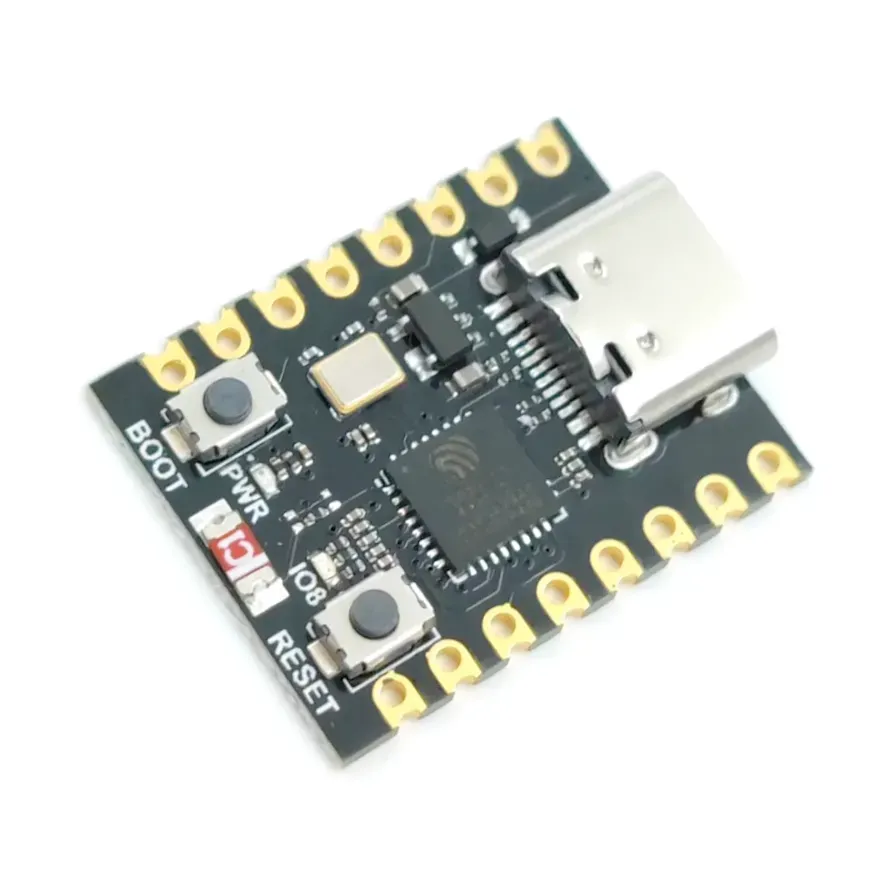
ESP32 C3 Super Mini development board is based on esp32c3 microcontroller and uses riscv32 architecture. Find its datasheet, features, pinout, technical specs and more.
$5 ??????
 nocturne rock
limber field
https://www.espboards.dev/esp32/esp32-c3-super-mini/
nocturne rock
limber field
https://www.espboards.dev/esp32/esp32-c3-super-mini/
It's a good board you'll get a wifi module with it
elfin sphinx
limber field
$5 ??????
yeah , those chinese board manufacturers can make it for really cheap
brisk zodiac
elfin sphinx
yeah , those chinese board manufacturers can make it for really cheap
yeah
 hasty pewter
from machine import Pin,UART
import network
import time

led = Pin(2,Pin.OUT)
uart = UART(1, baudrate=9600, tx=17, rx=16)
wifi = network.WLAN(network.STA_IF)
wifi.scan()

def connect():
    while True:
        wifi.connect('NerdsLivesInMybasement🤓','jerkinGNERDs3.14285714')
        stats_wifi = wifi.isconnected()
        if stats_wifi:
            print(f"WIFI CONNECTED || IP:{wifi.ifconfig()[0]}")
            return stats_wifi

wifi_status = connect()

def exekey(connected=True):
    if wifi_status:
        while connected:
            if uart.any():
                button =  uart.read(1).decode()
                return button

while True:
    key = exekey()
    if key:
        led.on()
        print(f"LED")
        time.sleep(0.5)
        led.off()
    else:
        led.off()
    time.sleep(0.2)
for some reason this doesn't wanna connect and the board is pointing at line and it's now frustrating
there is nothing totally wrong with the defined connect funtion
hasty pewter
limber field
https://www.espboards.dev/esp32/esp32-c3-super-mini/
Dude this thing is war like to make it boot micro python into it
hasty pewter
balmy lichen
```py
from machine import Pin, PWM, ADC
from time import sleep
servo_pin = Pin(...
Hi can I dm you
 whole echo
#'python -m serial.tools.miniterm 115200 --raw '
from machine import Pin,UART
import network
import time
led = Pin(2,Pin.OUT)
uart = UART(1, baudrate=9600, tx=17, rx=16)
wifi = network.WLAN(network.STA_IF)
wifi.scan()
def connect():
while True:
wifi.connect('NerdsLivesInMybasement🤓','jerkinGNERDs3.14285714')
stats_wifi = wifi.isconnected()
if stats_wifi:
print(f"WIFI CONNECTED || IP:{wifi.ifconfig()[0]}")
return stats_wifi
wifi_status = connect()
def exekey(connected=True):
if wifi_status:
while connected:
if uart.any():
button = uart.read(1).decode()
return button
while True:
key = exekey()
if key:
led.on()
print(f"LED")
time.sleep(0.5)
led.off()
else:
led.off()
time.sleep(0.2)
 hexed pond
Hi what are you doing hare?
cloud hinge
restive laurel
Anyone here made a Brain Computer Interface (BCI) using a raspberry pi or arduin...
i have studied the system a bit but i have not got one yet
 wraith belfry

hasty pewter
hexed pond
Hi what are you doing hare?


 balmy dirge
hey low level coders, I wanna brag about something.
I will build a whole operating system one day. hopefully a 64 bit one. from bare metal, even deeper than that. I will use actual electronic components
ICs, MOSFETs and BJTs, and of course all the other required components and material
it will take me a lot of time, but I will still do it some day
I can't promise it though
I will just try my best to achieve that
no matter how long that would take me. it could be even a decade
it's gonna be an interesting and painful journey!
something that I will most likely regret
ping me if you want to say something about it, all feedback will be appreciated
 lyric harbor
Hey, I'd appreciate feedback on my schematic, its a devboard based on the RP2040, I've never done this before so chatGPT came in clutch, but that's why I'm also asking for reassurance.
i cant send the pdf so let me get a photo real fast.
 hallow igloo
nuicew
 fiery lion
lyric harbor
fiery lion
lyric harbor
Cool work man idk much about microcontrollers but this is some cool stuff
 primal vortex
lyric harbor
Hey, I'd appreciate feedback on my schematic, its a devboard based on the RP2040...
primal vortex
lyric harbor
Hey, I'd appreciate feedback on my schematic, its a devboard based on the RP2040...
unable to provide feedback as I am not well educated on schematics but what did you use to make this?
errant wigeon
primal vortex
unable to provide feedback as I am not well educated on schematics but what did ...
https://www.kicad.org/
KiCad is a open source tool for designing PCBs, and includes a schematic layout engine. It's pretty great, though there are lots of other tools out there too
A Cross Platform and Open Source PCB Design Suite
errant wigeon
lyric harbor
Adafruit has a discord and in it there's a "help with hw design" channel. They probably will be well suited to help out with schematic designs
They also have a few dev boards with the rp2040, and show their hardware design: https://learn.adafruit.com/adafruit-feather-rp2040-pico/downloads
lyric harbor
Ah thanks guys, appreciate it
lyric harbor
primal vortex
unable to provide feedback as I am not well educated on schematics but what did ...
Yes, I used kicad, it was actually really simple to pick up if your ever interested
 urban junco
lyric harbor
urban junco
lyric harbor
Didn't know, kicad is this good
 hardy idol
need help
tidal haven
with?
 eternal sorrel
balmy dirge
ping me if you want to say something about it, all feedback will be appreciated
eternal sorrel
balmy dirge
ping me if you want to say something about it, all feedback will be appreciated
Why not make a discord server to drop updates in and for prople with similar interests could talk
balmy dirge
I already own one discord server though. It's been very inactive and silent for years and lost hundreds of people.
balmy dirge
eternal sorrel
Why not make a discord server to drop updates in and for prople with similar int...
It's an interesting idea after all. But I don't think I could manage something like that. I am usually pretty busy.
quaint nacelle
"Zulip" is an interesting offering, it's like a hybrid of Slack and Discord and a forum, sorta
I made one for my "covert open source" friends, cool so far.
eternal sorrel
balmy dirge
It's an interesting idea after all. But I don't think I could manage something l...
Oh well..
balmy dirge
eternal sorrel
Oh well..
Yeah. Anyway, are you interested?
quaint nacelle
Anybody in here ever programmed an "FPAA", an ANALOG programmable device? e.g. https://www.renesas.com/en/products/slg47004 ?
Renesas
SLG47004 is an AnalogPAK programmable mixed-signal IC with operational amplifiers, digital rheostats, EEPROM, and a wide set of analog and digital macrocells.
balmy dirge
eternal sorrel
Definitely
Oh really? I'm surprised actually.
eternal sorrel
balmy dirge
Oh really? I'm surprised actually.
Haha fair enough actually, i just love knowledge
It tingles my brain when i learn something new
🤤
balmy dirge
I agree
balmy dirge
eternal sorrel
Haha fair enough actually, i just love knowledge
if you wanna know, I recently got some of the parts I will need!
it is already making progress!!
I really hope it will work once it's finished.
and this project is incredibly insane. what I am planning for it is. I will first make 64 bit registers and 64 bit ALU. very complex, yet still I will try to figure it out somehow. those will be main components of the cpu. after that I will either buy some kind of RAM chipset or even connect consumer RAM (at least ddr3) to it.
and once I get those main components and connect all that to work. I will make more hardware such as PS/2 or maybe even USB interface. I prefer PS/2 because it has lower latency and it's simpler to implement. and a VGA interface. I maybe know some place where there is a whole storage of old VGA monitors and cables that is planned to be thrown away, so I will maybe take one monitor. and once I make the VGA interface I will maybe make graphics interface. that is just the beginning. but before implementing any visible graphics I will try writing some kind of firmware and flash it to memory. and finally after all that goes actual software development. a custom compiled programming language (probably my own version of C, probably a hybrid of C. C++ and BASIC. I will not remake those languages, I will just combine the things from those languages that I like. for example in BASIC I like how it has peek and poke and I thought it could be pretty cool to add in my own language for my own computer. alright so after I make the language I will start coding even further. I will make a bootloader, a file system, a kernel, and beyond all that to the point where I make desktop environment and applications, and boom, a whole PERSONAL COMPUTER from scratch is done... kind of.
it is very extreme and sounds very impossible. but I am enough crazy for that kind of project. and I will truly try my best to get all the resources.
I still can't promise any of that. it is way too extreme for me and I highly doubt it is possible for me. and even if it is possible, it would take me a very long time. I won't promise anything
eternal sorrel
balmy dirge
I really hope it will work once it's finished.
and this project is incredibly in...
Damn going full terry davis mode!
Yo make a server for this specific purpose
And invite me
And I'll help with what i can
And learn new stuff from you
quaint nacelle

I have a ton of old custom FPGA boards, and I'm trying to clear out my office. Anyone in the Bay Area want some FPGA boards for free? Here's a "build your own GPU" board I designed, with working PCIe, half a gigabyte of "VRAM", 63k LUTs, and 1080p 60Hz HDMI output. I have two.

 vxTwitter / fixvx
·
vxTwitter / fixvx
·
 brave prairie
I'm new to micropython. Many years ago I've played with microcontrollers in C but I don't recall much. I'm now looking around micropython doc and I've read a little about interrupts. was just curious to know what are the most common way to organize code.
what kind of techniques do you use to achieve "multitasking" do you use asyncio? do you write some kind of state machine?
Sorry for the vague question, I'm just trying to build a very wide understanding 😅
balmy dirge
eternal sorrel
Damn going full terry davis mode!
Maybe XD
balmy dirge
eternal sorrel
Yo make a server for this specific purpose
Like a whole community?
balmy dirge
I forgot to mention. If I actually build that thing. I'll also try making networking possible (wired). Maybe connect it to ethernet. There will be no speakers though. I don't want to make a sound card or sound interface. The only sound it will have is a buzzer, but only for troubleshooting. Thr buzzer will just buzz different patterns of sounds so I know if it's an error or something else. And if all that succeeds, there will be a problem. It will (probably) be unable to run any 3rd party software since it is my custom handmade cpu architecture, custom instruction set, custom firmware and OS. Everything will be custom. And probably the only software it could run is the one that I make specifically for it. Maybe, but just maybe if I "steal" already existing architecture such as intel x86 processors and even flash firmware like coreboot or libreboot. Then it could maybe run 3rd party software. If I actually "steal" (copy) the existing architecture then I'll first try booting linux on it. But my primary goal is to make my own os for my own architecture.
eternal sorrel
balmy dirge
Like a whole community?
Yeah why not 67 is greater than one or however the saying goes
eternal sorrel
balmy dirge
I forgot to mention. If I actually build that thing. I'll also try making networ...
Sounds like a lot of work 😋 and i love that
balmy dirge
eternal sorrel
Yeah why not 67 is greater than one or however the saying goes
Oh. That could be interesting and complicated. I first have to tidy some things up in life before making a whole community
balmy dirge
eternal sorrel
Sounds like a lot of work 😋 and i love that
it is a huge amount of work! The whole project could take me years. Mostly because of material gathering and software development at the end. Assembling the circuit could take me just a couple weeks or one month. Which is very fast for such project
First I have to get the parts. Mostly ICs, wires, cables, many breadboards for prototyping and troubleshooting. That could take me months to collect all that. For example to build a 64 bit ALU (Arithmetic Logic Unit, idk if I spelt it right), it would need around 256 ICs with logic gates. Very impractical, so I could decrease the amount by using more complex ICs. So the amount could go down from 256 chips to around 50 or 30.
But that's just the ALU, let's not forget the rest of the CPU and the custom motherboard including the connectors for PS/2 keyboard and perhaps mouse.
eternal sorrel
balmy dirge
Oh. That could be interesting and complicated. I first have to tidy some things ...
Yeah fair enough.. well keep me updated with the whole thing
balmy dirge
If I ever make the community you can join if you want, and get updated
eternal sorrel
balmy dirge
First I have to get the parts. Mostly ICs, wires, cables, many breadboards for p...
So much bigs words for my small brain
eternal sorrel
balmy dirge
If I ever make the community you can join if you want, and get updated
👅
Tell me if you do
balmy dirge
eternal sorrel
So much bigs words for my small brain
Long story short. I'll need many things.
balmy dirge
eternal sorrel
Tell me if you do
Sure!
eternal sorrel
balmy dirge
Long story short. I'll need many things.
Wish you much of luck, hit me up if you needed something i might be able to help
balmy dirge
Thank you very very much!
Hey I have a funny thought. A joke actually
Wanna hear it?
balmy dirge
Alright
Imagine the computer is finished, and then Linus Sebastian from Linus Tech Tips reviews it XD
eternal sorrel
balmy dirge
Imagine the computer is finished, and then Linus Sebastian from Linus Tech Tips ...
That computer is doomed bru 😭
balmy dirge
why?
brisk zodiac
hi gais
brisk zodiac
bro i have a buisness ideas not specifically based on mcus but it is something
hallow igloo
quaint nacelle
https://vxtwitter.com/ptrschmdtnlsn/status/1978582368140083556
That’s cool
 unkempt hawk
Hi guys
 normal galleon
hi
brisk zodiac
who wanted to make a bci
 bold drift
hi guys im here new to learn python
 ripe wigeon
Guys I am new into programming and interested in all the robotics and stuff, what do you recommend should I just start programming an Arduino or wait a bit?
 noble wedge
ripe wigeon
Guys I am new into programming and interested in all the robotics and stuff, wha...
noble wedge
ripe wigeon
Guys I am new into programming and interested in all the robotics and stuff, wha...
Learn the basics of python: functions, data types, loops, etc., and then try some basic projects like controlling LEDs, follow some tutorials, and when you have a basic understanding of all those things, try making your own project. When doing your own project, you probably will run into some problems, but you really learn a lot from errors.
Just don't give up!
Raspberrypi.org has some great tutorials: https://projects.raspberrypi.org/en
Adafruit has lots of good tutorials too: https://learn.adafruit.com
 supple vault
bold drift
hi guys im here new to learn python
supple vault
bold drift
hi guys im here new to learn python
Welcome!
tidal haven
ripe wigeon
Guys I am new into programming and interested in all the robotics and stuff, wha...
Could get some cheap hobby servo motors to play with too, a little while ago i bought a cheap 6 DoF robot arm, that uses cheap servos, so it's not very precise, but pretty fun (i drove it via a Pi and I2C servo driver)
ripe wigeon
tidal haven
Could get some cheap hobby servo motors to play with too, a little while ago i b...
Aren't Pi(s) very expensive tho?
 zenith niche
I want to send 3v or 5v signals from something connected to usb port controlled by python. What's the easiest way to do this?
tidal haven
you don't have to use a pi, can easily drive a servo via a microcontroller
zenith niche
tidal haven
you don't have to use a pi, can easily drive a servo via a microcontroller
OK cool could you please suggest a microcontroller that works well with python?
tidal haven
i used a raspberry pi pico recently, for driving stepper motors, via micropython and the PIO support
should work fine for servos too
zenith niche
tidal haven
i used a raspberry pi pico recently, for driving stepper motors, via micropython...
ah right, thank you. I was after something that works with full Python. Perhaps I'm asking in the wrong place? Just want something that plugs into a normal USB port and sends signals to various pins Python instructs
tidal haven
Not exactly sure what you're trying to control, but you can use an FTDI chip attached to the USB port to set pin states, looks like Adafruit provide some python libraries to interface with these chips too - https://www.adafruit.com/product/2264

Wouldn't it be cool to drive a tiny OLED display, read a color sensor, or even just flash some LEDs directly from your computer? Sure you can program an Arduino or ...
Or you can use a microcontroller with usb support and run a program on it that takes serial input, and sets pin according to certain serial commands
elfin sphinx
zenith niche
ah right, thank you. I was after something that works with full Python. Perhaps ...
arduino with the pyfirmata library
how it will work is , there will be a python script running on your PC that will control the arduino connected to the USB port , you can set its pins do whatever you want
the drawback is that , the code that tells arduino what to do lives on your PC , not on the arduino (because arduino doesnt support python) , so whenever you unplug or shut off your PC , the code also stops.
but if you are looking for something that just stays connected to your PC all the time and you want it to work when its connected, a simple arduino bboard with pyfirmata is probably good enough
zenith niche
elfin sphinx
arduino with the pyfirmata library
how it will work is , there will be a python...
Beautiful tyvm. This is exactly what I'm after.
I am specifically trying to control several relays and in the meantime I've ordered this, https://www.aliexpress.com/item/1005007822223114.html , expecting this would simplify the hardware esp wrt wiring
The problem now is that I have no idea how I'll control this thing. Maybe this? https://github.com/Brasme/usb_ch340_4x_relay_control . I'll have a tinker with it when it arrives

GitHub
USB CH340 Chip 4x Relay Control in Python. Contribute to Brasme/usb_ch340_4x_relay_control development by creating an account on GitHub.
elfin sphinx
yeah what you linked seems fine
but that module looks more like "plug it directly into PC and control it with code" , rather than "connect it to a microcontroller and code the microcontroller to talk to it" , but you can do it if you want to , its just like , taking 4 steps to solve a 2 step problem
i would have recommended an arduino with a relay module , much cheaper and you will find tons and tons of wiring guides / tutorials about it on internet
brisk zodiac
elfin sphinx
arduino with the pyfirmata library
how it will work is , there will be a python...
you can probably use ta the serial library to read cmds that u can code in cpp
hasty pewter
bold drift
hi guys im here new to learn python

 ripe igloo
Hey guys! I'm trying to setup micropython with a rp2040-zero.
I can burn the firmware via Thonny (or manually) sucessfully. However, after that Thonny isn't detecting the device as /dev/tty...
I'm on Mac OS, any tips here?
 static kiln
Would a thermal monitoring code for an android flagship phone be considered a microcontroller?
brisk zodiac
static kiln
Would a thermal monitoring code for an android flagship phone be considered a mi...
no
 cold hinge
brisk zodiac
no
cold hinge
brisk zodiac
no
This is an microcontroller
 brisk zodiac
cold hinge
This is an microcontroller
brisk zodiac
cold hinge
This is an microcontroller
yas
brisk zodiac
cold hinge
This is an microcontroller
r u indian??
cold hinge
ye
tidal haven
GitHub
A floor-routing WAN implementing a chat over bare-LoRa (no LoRaWAN). - antirez/freakwan
(uses micropython)
brisk zodiac
tidal haven
https://github.com/antirez/freakwan
lora
u use lora
i dont have lora
module
 hot scaffold
Just ordered a LilyGo T-Dongle-S3 from Amazon. 🙂 It sounds like a good way to learn about ESP-32, hacking, and MicroPython.
Figured that even if I can't get it working, it only cost about $30.
But yeah. This sounds like it's going to be some fun. 🙂 Plus I got a study guide for the Linux Essentials exam.
brisk zodiac
hot scaffold
Just ordered a LilyGo T-Dongle-S3 from Amazon. 🙂 It sounds like a good way to l...
yeah its good
brisk zodiac
hot scaffold
Figured that even if I can't get it working, it only cost about $30.
30$ r u kidding me
tidal haven
brisk zodiac
lora
I've not played with lora yet, something I keep meaning to do. Looks like that dongle is $11 on aliexpress
brisk zodiac
tidal haven
I've not played with lora yet, something I keep meaning to do. Looks like that ...
11$ like i find it for round 2$
 woeful parrot
tidal haven
i used a raspberry pi pico recently, for driving stepper motors, via micropython...
woeful parrot
tidal haven
i used a raspberry pi pico recently, for driving stepper motors, via micropython...
I have a rasberry pi too, but i cant do anything with it for some reason..
i connect the type c to my pc, and it recognizes it but i cant seem to do anything with it
it has some circles to the edges of it but i cant connect any wires to it
brisk zodiac
woeful parrot
it has some circles to the edges of it but i cant connect any wires to it
can u go into more detail
elfin sphinx
yes
elfin sphinx
what is going wrong ? what do you need help with ?
im not sure , ill check when im back , im not familiar with the timing functions and how they work
like , afaik , the us sleep is probably not accurate and so on
 grand path
esp 32
woeful parrot
brisk zodiac
can u go into more detail
Absolutely, so basically, i've done some research and found out that i bought the rasberry pi without integrated headers! Isn't that fabulous? Anyways, because of the lack of the headers, it renders the rasberry pi useless..
And i was just wondering if there is any way i can do something with it
brisk zodiac
woeful parrot
Absolutely, so basically, i've done some research and found out that i bought th...
wow
brisk zodiac
woeful parrot
And i was just wondering if there is any way i can do something with it
solder
woeful parrot
brisk zodiac
solder
I have absolutely no idea how to solder and unfortunately i dont have a solder in possesion..
so yeah i might aswell stick to the arduino uno lol
brisk zodiac
woeful parrot
And i was just wondering if there is any way i can do something with it
dosent just inseritng the wires and like like twist them to fix it in place
woeful parrot
brisk zodiac
dosent just inseritng the wires and like like twist them to fix it in place
Oh is that possible?
brisk zodiac
woeful parrot
Oh is that possible?
i think so
but just see if its like touching the golden color points
woeful parrot
i will try it another time cause ive got h/w
 amber cypress
Just a recommendation for better readability: use "underscore" for variable names, such as adc_pin, sample_rate, period_ms, sample_amount, ...
 soft prawn
hello
cold hinge
Heewllloi
 viral glen
i plan on putting one of my scripts on a raspberry pi pico
what would i do to convert python to micropython
https://github.com/Varanslash/Cobalt-Assembly
this is the script

GitHub
a version of asm made by me in my free time. based on 6502 assembly and inspired by c--. - Varanslash/Cobalt-Assembly
 tacit badger
woeful parrot
i will try it another time cause ive got h/w
tacit badger
woeful parrot
i will try it another time cause ive got h/w
yoo try buying a few header pins since the pi pico isnt pre soldered and try soldering it cuz at some point you will have to learn to solder
gng how do i connect my opencv file with the microcontroller file of the ESP32 cam module?
woeful parrot
tacit badger
yoo try buying a few header pins since the pi pico isnt pre soldered and try sol...
thanks man thats what im finna do
tacit badger
woeful parrot
thanks man thats what im finna do
ye if u need any help then lmk
ill help as much as possible since im new too
 hallow pollen
 honest drift
🥲
brisk zodiac
tacit badger
gng how do i connect my opencv file with the microcontroller file of the ESP32 c...
idk i just connect the cam module to my phone and process the data and send the result back
 pale bloom
ansible
 maiden crown
Hello I am learning file handling, data analyst should I message here ?
maiden crown
tacit badger
there are other chats for those fields
Ok thanks
tacit badger
maiden crown
Ok thanks
np
tacit badger
brisk zodiac
idk i just connect the cam module to my phone and process the data and send the ...
wait how do u upload code from mobile?
nocturne rock
tacit badger
wait how do u upload code from mobile?
Wait does opencv have modules for esp32 ?
brisk zodiac
tacit badger
wait how do u upload code from mobile?
using arduino's app
 thorny helm
I'm trying to mount an sd card in circuitpython, and I've checked every pin multiple times. Is there anything wrong with my code or do I need to buy a new breakout board (probably broke it when soldering). I get a OSError: no SD card on the sdcard = sdcardio.SDCard(spi, cs) line. This is my code:
`# SPDX-FileCopyrightText: 2021 Kattni Rembor for Adafruit Industries
SPDX-License-Identifier: MIT
"""
CircuitPython single MP3 playback example for Raspberry Pi Pico.
Plays a single MP3 once.
"""
import board
import busio
import sdcardio
import storage
import audiomp3
import audiopwmio
import digitalio
import microcontroller
audioselected = False
mp3files = ["file1.mp3", "file2.mp3", "file3.mp3", "file4.mp3"]
fileselected = 0
spi = busio.SPI(board.GP2, board.GP3, board.GP4)
cs = board.GP1
sdcard = sdcardio.SDCard(spi, cs)
vfs = storage.VfsFat(sdcard)
button = digitalio.DigitalInOut(board.GP9)
button.direction = digitalio.Direction.INPUT
button.pull = digitalio.Pull.UP
button2 = digitalio.DigitalInOut(board.GP10)
button2.direction = digitalio.Direction.INPUT
button2.pull = digitalio.Pull.UP
button3 = digitalio.DigitalInOut(board.GP17) # 15
button3.direction = digitalio.Direction.INPUT
button3.pull = digitalio.Pull.UP
button4 = digitalio.DigitalInOut(board.GP16) #14
button4.direction = digitalio.Direction.INPUT
button4.pull = digitalio.Pull.UP
audio = audiopwmio.PWMAudioOut(board.GP8)
while audioselected == False:
if button.value == False:
fileselected = 0
audioselected = True
if button2.value == False:
fileselected = 1
audioselected = True
if button3.value == False:
fileselected = 2
audioselected = True
if button4.value == False:
fileselected = 3
audioselected = True
decoder = audiomp3.MP3Decoder(open(mp3files[fileselected], "rb"))
audio.play(decoder)
while audio.playing:
pass
print("Done playing!")
microcontroller.reset()`
I have tried formatting the card in FAT and FAT32 formats
brisk zodiac

GitHub
GPTArm. Contribute to Intuex/GPTArm development by creating an account on GitHub.

GitHub
Contribute to Ansh-droid-glitch/GPTArm development by creating an account on GitHub.
limber field
This would assist , physically challenged people GREATLY @brisk zodiac
brisk zodiac
limber field
This would assist , physically challenged people GREATLY <@1321897497991446568>
Thank you
restive laurel
brisk zodiac
https://github.com/Ansh-droid-glitch/GPTarm
thats cool
brisk zodiac
restive laurel
thats cool
Thanks
restive laurel
brisk zodiac
Thanks
next step would be adding a BCI and implementing its features somewhere
brisk zodiac
restive laurel
next step would be adding a BCI and implementing its features somewhere
Ik i need to buy materials for that plus im gna add wheels
 abstract zephyr
brisk zodiac
https://github.com/Ansh-droid-glitch/GPTarm
abstract zephyr
brisk zodiac
https://github.com/Ansh-droid-glitch/GPTarm
What does the arm itself look like ? Good job
brisk zodiac
abstract zephyr
What does the arm itself look like ? Good job
well u could create ur iwn and cgnage the dimensions in the cpp file cuz the one i made is shitty
tacit badger
nocturne rock
Wait does opencv have modules for esp32 ?
idk was js asking cuz i made an ML algo for face recognition so wanted to test it
 queen verge
Can anyone put me through how ccs work
 ember sequoia
Hello! Is anyone here familiar with fNIRs? I am trying to build a headband myself, big emphasis on trying
 stoic summit
Hi guys ! I'm trying to get into embedded system proggraming and baremetal programming, any advice on where to start and how?
 tidal kestrel
queen verge
Can anyone put me through how ccs work
tidal kestrel
queen verge
Can anyone put me through how ccs work
you mean css?
queen verge
Yes
tidal kestrel
html puts stuff on a web page (website) like buttons, text boxes, nav bars .etc,,, css makes it look pretty,,, then js makes it actually do things
paper pike
how can I use camras to take photos using python
spiral sandal
paper pike
how can I use camras to take photos using python
on what peripheral ? esp32cam ? phone ? tablet ? ios ? android ?
 river badger
I am btech 2nd year engineering student.
I have been assigned a project of mobile manipulator.
I m thinking about controlling it through hand-signs (like one hand to control the arm and second to control the movement).
I want all of it to also show in real-time live screen with my gesture working as well.
I m confused like from where I should start.
If possible I just need a flowchart for the project.
(Like which libraries documentation I need to read)
paper pike
So android
spiral sandal
paper pike
So android
then the easiest way could be with a python wasm application hosted eg on github pages, here's a sample https://pygame-web.github.io/showroom/pygbag.html?-i#src/test_vidcap.py
it is pygame camera module based but code is async, here's the code https://github.com/pygame-web/showroom/blob/main/src/test_vidcap.py
GitHub
Game on ! Contribute to pygame-web/showroom development by creating an account on GitHub.
 sullen sand
tidal kestrel
html puts stuff on a web page (website) like buttons, text boxes, nav bars .etc,...
sullen sand
tidal kestrel
html puts stuff on a web page (website) like buttons, text boxes, nav bars .etc,...
basically HTML (Hypertext Markup Language)builds the page, CSS (Cascading Style Sheets) styles it, and JavaScript makes it interactive @queen verge
tidal kestrel
well dont you like to copy people
 pliant nebula
.
 teal hamlet
Hello everyone.. I am doing a DIY project using Raspberry Pi and would like to connect it to a GSM Module.. can anyone suggest one which you have used and works well?
 plain basin
Use the one which is worked w/ arduino nano. Actually if it used the uart protocol so that which works with arduino works with rpi tbh :))
Also check out the Waveshare SIM7028 NB-IoT HAT for Raspberry Pi, Supports Global Band NB-IoT Communication. I think it will fit your needs
elfin sphinx
<@&831776746206265384>
 weak basin
!cleanban @restive island spam
hasty zealotBOT
:incoming_envelope: :ok_hand: applied ban to @restive island permanently.
 karmic elm
what are micro controllers?
 elfin chasm
hi, Im trying to make device like the elegoo streamdeck. I managed to send data via bluetooth with my esp 32-wroom to my pc. I made a python script that checks if the pc is connected with a device with a certain device ID and if yes it gets the port and waits for data to arrive. everything works but I got one weird problem. Im running windows 11 on my pc and when im running the script, and the esp is connected every hour or so, my usb devices fail for like 10 seconds. so I cant use my mouse and my headset disconnects. I looked in the event viewer for errors and actually found something related to my issue. it always pops up after the usb "fail". BTHUSB event: 18. if you know anything plsss tell me, im ging insane. heres my python code btw :
hasty zealotBOT
elfin chasm
Please react with ✅ to upload your file(s) to our paste bin, which is more accessible for some users.
 tropic burrow
Please what do i need to know to be able to send instructions to my esp32 connected to my pc via ble so that say a 1 hand gesture captured from my pc camera means on led connected to pin 1 and a 2 hand gesture means power the servo motor connectd to pin 4
spiral sandal
tropic burrow
Please what do i need to know to be able to send instructions to my esp32 connec...
what software platform is doing the gesture recognition ?
 plucky granite
karmic elm
what are micro controllers?
plucky granite
karmic elm
what are micro controllers?
Bare metal computers made to work with hardware after having code applied, no GUI of any sort just code and bare hardware
 open bridge
How do i code an stm32 in python?
Can i just code python in arduino ide and use the stm32 library?
urban junco
Nah, u gotta use cubeIDE
urban junco
open bridge
Can i just code python in arduino ide and use the stm32 library?
But, I support emb C lang ig...so u can python mate
Or if u really want to go with python, go for micropython and stuff...
 neat plover
hey guys i need help trying to figure this esp32 thing out
i connected a screen to it but the code isnt launching i keep getting an error message
Failed to install platform: 'esp32:3.3.6'. 4 DEADLINE_EXCEEDED: context deadline exceeded (Client.Timeout or context cancellation while reading body)
i tried to download esp32 espressif library and i get htis error i tried asking chatgpt and still
 exotic oar
try it on cloud ig
 muted wigeon
I’m a 3rd-year Electrical Engineering student doing 100 Days → 100 IoT Projects with MicroPython (ESP32, sensors, dashboards).
Everything is open-source for students. Hardware costs add up, so GitHub Sponsors helps fund boards and sensors.
Repo: https://github.com/kritishmohapatra/100_Days_100_IoT_Projects can anyone sponsor me for the hardware?
GitHub
A 100-day challenge exploring IoT and embedded systems using ESP32, ESP8266, and Raspberry Pi Pico with MicroPython. Each day covers a new sensor or module with complete code, circuit diagram, and ...
 summer ridge
muted wigeon
I’m a 3rd-year Electrical Engineering student doing 100 Days → 100 IoT Projects ...
summer ridge
muted wigeon
I’m a 3rd-year Electrical Engineering student doing 100 Days → 100 IoT Projects ...
thats a massive grind for sure good luck with the sponsors
muted wigeon
muted wigeon
I’m a 3rd-year Electrical Engineering student doing 100 Days → 100 IoT Projects ...
Can anyone sponsor for the hardware Cost?