#microcontrollers
1 messages · Page 5 of 1
 elfin sphinx
 hardy adder
Oh okay
elfin sphinx
you can read more at https://docs.micropython.org/en/latest/rp2/quickref.html
hardy adder
Noted, thx bro
elfin sphinx
👍
 smoky meadow
lf for someone who can help with basics of raspberry pi pls @ me
elfin sphinx
smoky meadow
lf for someone who can help with basics of raspberry pi pls @ me
just ask your question
if someone knows theyll answer
 hallow igloo

Reddit
Explore this post and more from the techsupport community
Idk if someone can help me abt this, but that would be helpful
elfin sphinx
is it possible ? sure (just bypass the internal charging circuit with an external lipo charger module
will it be as elegant ? unless you are extremely delicate while opening it and adding that extra circuitry , NOPE
hallow igloo
Can't I just re-solder
elfin sphinx
resolder what ? to where ?
you mean , the charging speed was great but its now pretty low ??
 errant wigeon
It looks like the headphones use a lipo (or the most common replacement battery is a lipo). Given that, I'd personally advise against messing with the charge current. Lipo's can quickly become spicy pillows when you mess with their charging current and they're not fun when they catch on fire
 tulip cargo
hello everyone,
I am a new user of esp32 using micropython and in this field in general, I am facing a problem with sending data from the esp32 to a server using http request, Idk if it the best solution to use http requests to send a file, I have heard abut ftp, but I have no idea about it, and Idk what are the best protocols to use in this situation, I will be thankful for any help or guidance from you, and thanks in advance.
elfin sphinx
what kind of files are you sending ? what is the size of these files ??
where is this server you are talking about hosted ?
and also where does esp32 come in picture in all of this ??
tulip cargo
elfin sphinx
what kind of files are you sending ? what is the size of these files ??
where i...
it is a csv file, the size is 39kB, the server is in the local host, and I have a hand on it
 elfin sphinx
tulip cargo
it is a csv file, the size is 39kB, the server is in the local host, and I have ...
elfin sphinx
tulip cargo
it is a csv file, the size is 39kB, the server is in the local host, and I have ...
then plain http transfer is just fine
tulip cargo
ftp_password = 'rNrKYTX9g7z3RgJRmxWuGHbeu'
import ftplib

# Initialize FTP client with longer timeouts
ftp = ftplib.FTP(timeout=30)

try:
    ftp.connect(ftp_server, ftp_port, timeout=30)
    ftp.set_pasv(True)  # Enable passive mode
    ftp.login(ftp_user, ftp_password)
    print("Connected to FTP server")
except ftplib.error_perm as e_perm:
    print(f"FTP Permission Error: {e_perm}")
except ftplib.error_temp as e_temp:
    print(f"FTP Temporary Error: {e_temp}")
except Exception as e:
    print(f"An error occurred: {e}")
finally:
    ftp.close()
Started webrepl in normal mode
An error occurred: Could not connect to ('44.241.66.173', 21)```I got this error while trying to establish an ftp connection between esp32 and the server
 errant shell
How is your ESP32 connected to the network? Are you sure 44.241.66.173 is the correct IP address? Which FTP server do you have running at that IP?
 torpid verge
tulip cargo
hello everyone,
I am a new user of esp32 using micropython and in this field in ...
torpid verge
tulip cargo
hello everyone,
I am a new user of esp32 using micropython and in this field in ...
Using urequests (now renamed to requests) is the standard http client. You can open a file and then send the stream, that way there is no need to allocate a 39kb buffer. There is also aiohttp in case you use asyncio (take a look at asyncio if you haven't)
 covert ore
Could someone help me with code?
elfin sphinx
covert ore
Could someone help me with code?
dont ask to ask , just ask your question
 shy vale
which microcontroller is best for running DL models like YOLOv5
arduino, stm or esp32
can't go beyond that due to budget constraints
i want the MCU to communicate with multiple devices and run YOLOv5 which gets input from a camera connected to the board in real-time
i have looked in to NVIDIA jetson and rpi, but i am hoping for something on the cheaper side
errant wigeon
Unfortunately at that scale you're probably not going to be able to run much in the way of a deep learning model on a micro. beyond that, to get the yolo stack to work you're going to need at the very least an embedded linux environment like you have on a pi or Jetson and you'll need to compile PyTorch for the hardware architecture as (at least this was true recently) they don't build for that hardware (so there's no wheels). There are cheats where you can stream data from a micro to a server, run a model on the server, and do things with the result, but streaming data gets to be a pain and adds costs elsewhere
elfin sphinx
there might be some way where you can get a very light version tenserflow light to run on a teensy board with a simple NN (saw it in a yt video)
but again , it is bit expensive than arduino boards , but cheaper than jetson nano
errant wigeon
Yeah there's some awesome ways to eek out more from micro's, and TF light is neat, but for a yolo model you'd have to figure out how swap the model from pyTorch to TF, then to tf light which, some folks are great at that kind of work but boy it'd baffle me. Streaming data seems wildly easier but even that is far from "easy".
errant shell
For computer vision tasks on microcontrollers check out OpenMV - I believe there might be some object detection support there
 cloud hinge
Can pin placement mistake make all pins act in reverse?
cloud hinge
Or can magnets from a motor cause the issue. Seems a pin misplacment possibly was causeing my code to work correctly and now i unplugged everything i dont remeber what the misplacmet was and now my scale not updateing either. Possibly. I think the pin misplacmet was also causing the motor to reverse. Bluetooth still working with microcontroller still with pump and pump directions work both ways now but everything is in reverse.
For l298n motor controller with linear actuator and pump
Theres 4 in pins 1,2,3,4 that corespond to esp32. D2, d16, d15, d12
I think the code might have been written to work backwards. So much work lol..
I put it on an expansion board and worked for a bit then i did some unplugging and plugging back in pins based on schematics
smoky meadow
yeah i get that now but more of the board purpose
oh i see so you just run the code and give it 8 values with it
Afbeelding
but what do those do excactly cu sort of a way to create more gpio spots but not sure
is the goal of this just to show that all 8 pins of the (.. dunno what it is called) are on the > more this part
pls @

 elfin sphinx
search for datasheet of the ic to see how it functions , which pin corresponds to what , and so on
 limber field
smoky meadow
smoky meadow
limber field
smoky meadow
smoky meadow
why would they do the yellow cable to the left side and not to right?


This is my progress so fair
@elfin sphinx
also not sure how the should be 26 useable pins on rpio 4 can find obly 17 gpio x
elfin sphinx
smoky meadow
why would they do the yellow cable to the left side and not to right?
as long as the knob isnt operating any sort of communication protocol like SPI , it shouldnt matter which pin you use
elfin sphinx
smoky meadow
<@671318664280145920>
also not sure how the should be 26 useable pins on rpio 4...
not sure what you mean by this

 elfin sphinx
smoky meadow
so like this?
elfin sphinx
smoky meadow
so like this?
this only shows the first 26 pins out of total 40
smoky meadow
elfin sphinx
this only shows the first 26 pins out of total 40
so if not volt pin or gp you should be good?
elfin sphinx
yes , those 3.3v and 5v pins output a fixed voltage , and gnd is always 0v
so you cannot control those pins through your program
what you can control is all the other GPIO pins
also , please follow a pin diagram that has all the pins listed on it since the one you showed is incomplete
smoky meadow
elfin sphinx
also , please follow a pin diagram that has all the pins listed on it since the ...
you im not done yet
yeah
and why are those special?
 elfin sphinx
smoky meadow
and why are those special?
elfin sphinx
smoky meadow
and why are those special?
SPI, I2C , UART are special protocols used to communicate between devices
those pins have the capability of talking in that protocol , hence they are special
you can use them as normal pins too
but if you have some device like a lcd display and it uses SPI communication , then you should connect that display to SPI pins
smoky meadow
alr thx for your help and time
elfin sphinx
no worries 👍
smoky meadow

Got this rn think im gonna use this use button is kinda blockef


It s gonna be a mess you need to switch the rotatory hope they won t be too annoying
 elfin sphinx
dont spam please
this is not a channel to vlog your journey
smoky meadow
but what is wrong seems right
smoky meadow
what would you like to see removed the resistors on 4x8
smoky meadow
smoky meadow
still stuck on this btw
elfin sphinx
circuit diagram(on paper or on any digital site) + photo of setup + code + errors + expected behaviour + what actually happens = a VERY HIGH chance of getting the help you need
" my circuit aint working , help " + random picture without any context = a VERY LOW chance of getting the help you need
you decide if you want help or sit there with a broken circuit
 smoky meadow
elfin sphinx
circuit diagram(on paper or on any digital site) + photo of setup + code + error...
smoky meadow
elfin sphinx
circuit diagram(on paper or on any digital site) + photo of setup + code + error...
don thave ocde
elfin sphinx
smoky meadow
how am i supposed to know which rotary sensor are you using , what pin of that rotary sensor is what , what pin of your LED display is what
you dont have to use kicad , it can be a bit complicated. there are other online simpler alternatives as well like easyeda , fritzing etc. paper circuit diagram is fine as long as you specify what pin is what and draw some good lines since these lines are hard to follow
you dont have to specify those breadboard numbers upto 60 since they are uselsess
elfin sphinx
smoky meadow
don thave ocde
how can the circuit without without some code ?
you still havent given information like photo of setup , expected behaviour + what actually happens
so i literally dont know what you want the circuit to do and what it actually does
 light ivy
Can an sg90 servo be powered by the +5V pin on a Raspberry Pi? is this recommended? otherwise, should a 5V power supply be used? would 4 x 1.5V battery work?
is the operational voltage 4.8V or 4.8-6V? on most websites it says 4.8V, but the datasheet http://www.ee.ic.ac.uk/pcheung/teaching/DE1_EE/stores/sg90_datasheet.pdf says 4.8-6V.
smoky meadow
elfin sphinx
how can the circuit without without some code ?
the hardware first need to be right before i can code
smoky meadow
elfin sphinx
how am i supposed to know which rotary sensor are you using , what pin of that r...
im using a rotary a 1x8 and a 4x8 segement
Wanna make a game where you scroll the number with scrollthing it will beep when you get close and harder when ur on it you press the scrollthing and it will add to the number when you get 1 it will add to the 4 numbers so you guessed 18 18.. 1815 and if all are guessed led will glow and will show a code on it after x amount of time.sleep()
How should i place it on my gpio for a logicol structure also needs to start without screen so with a button
smoky meadow
@errant wigeon are you able to help 🙂
smoky meadow
Nice im getting ghosted
elfin sphinx
i was away lol
wdym ghosted ?everyone is volunteer here , so you cant expect help on demand 🤷♂️
anyway
elfin sphinx
smoky meadow
im using a rotary a 1x8 and a 4x8 segement
didnt you already have everything connected ?
elfin sphinx
smoky meadow
im using a rotary a 1x8 and a 4x8 segement
that does not tell me what pins they have since there are lots of rotary encoders , and i do not know which one you have , how many pins it has , which pin is connected where and so on
elfin sphinx
smoky meadow
Wanna make a game where you scroll the number with scrollthing it will beep when...
i think i get what you mean 🤔
actually , i dont
errant wigeon
smoky meadow
Nice im getting ghosted
Please be mindful of everyone's time and ability to be present. This is the first time I've been able to be online in 5 hours, it has nothing to do with ghosting and just the fact that we all have our own personal obligations to attend to. As Saul pointed out, we're volunteers and as such, we help as we're able to.
elfin sphinx
can you work through an example of what you want to happen ?
(or tell me if i have gotten what you said correctly)
so initially(when you just power your circuit on) am guessing all the displays ( the 4 digit and 1 digit ) will be off
as you start rotating your rotary encoder , the number on the single digit display will start going from 0->1->2->.....8->9->0->1->..... , when you stop rotating the thing , the display will stop as well (say it was on 4 when you stopped rotating your knob , so it will freeze on 4)
so when it is on 4 , and you press the rotary thing , 4 will get submitted to your python program , and it will check with the random number the computer had in mind
if it was 4(the random number computer had in mind) , then the computer will show some sort of 4 digit code on the 4 digit display after some x seconds of delay
and if it wasnt 4 , the process will restart from 0
is this what you want to happen on your circuit ??
and please give the specification of your rotary encoder ( with its pin diagram) and the specification of your both displays (with pin diagrm) so that we know what components you are working with here
(from what i understand , the 7 segments can have any gpio connected to it , except the power pins(we already discussed this) , and as long as your rotary thing doesnt use any protocol like I2C or SPI , you can connect that to any gpio as well)
errant wigeon
elfin sphinx
and please give the specification of your rotary encoder ( with its pin diagram)...
Build off of this, there's so many out there that it's hard to know which one you're using:
https://www.sparkfun.com/categories/524
This is the options from a small vendor, whereas
https://www.mouser.com/c/electromechanical/encoders/?technology=Rotary
This is a larger vendor. It's really hard to know what part your using, so if there's a wiring issue we can't really begin to help you look for it.
smoky meadow
elfin sphinx
didnt you already have everything connected ?
I do but not good Just came back from supermarket to Cook for my mom
smoky meadow
elfin sphinx
that does not tell me what pins they have since there are lots of rotary encoder...
Hit has 5 pins Total is there like a seriële number on it to check the spefic type?
errant wigeon
But even before that, have you gotten to rotary encoder to work on it's own? Let's make sure your code can work with each part own its own before we start trying to put everything together. It's going to be really hard to know why something doesn't work if you do everything at once
smoky meadow
errant wigeon
But even before that, have you gotten to rotary encoder to work on it's own? Let...
Used the rotary and 1x8 segment before on it s own will show in 2 min
elfin sphinx
smoky meadow
Hit has 5 pins Total is there like a seriële number on it to check the spefic ty...
could be
you can send a clear picture of it so that we have at least some tangible thing to grab onto
smoky meadow
import random
import time
import RPi.GPIO as GPIO


GPIO.setmode(GPIO.BCM)
#in en output

# num_display = {
#     1: 12,  #A
#     2: 16,  #B
#     3: 13,  #C
#     4: 19,  #D
#     5: 26,  #E
#     6: 21,  #F
#     7: 20      } #G


NUMBERS = {
    0: [12, 16, 13, 19, 26, 21],
    1: [16, 13],
    2: [12, 16, 20, 26, 19],
    3: [12, 16, 20, 13, 19],
    4: [21, 20, 16, 13],
    5: [12, 21, 20, 13, 19],
    6: [12, 21, 20, 26, 19],
    7: [12, 16, 13],
    8: [12, 13, 16, 19, 20, 21, 26],
    9: [21, 12, 16, 20, 13, 19],
}


random_num = random.randint(0, 9)
GPIO.setup(NUMBERS[random_num], GPIO.OUT)
GPIO.output(NUMBERS[random_num], GPIO.HIGH)

time.sleep(10)
GPIO.cleanup()
 errant wigeon
Do you have more than one bread board?
 elfin sphinx
oof
smoky meadow
Only this extra
elfin sphinx
yeah , thats fine too
errant wigeon
That'll work! Let's split the parts off into their own sections, so it's easier to mange cables because anything could be the problem in the above picture. Breaking the problem down to small known sections is going to help
smoky meadow
So you want the 1x8 for example on 1 board?
#importeer GPIO en time package
import RPi.GPIO as GPIO
import time
from RPi import GPIO
from time import sleep
clk = 17
dt = 18
#gebruik BCM mode voor de pin nummering (conform breakout)
GPIO.setmode(GPIO.BCM)
GPIO.setup(clk, GPIO.IN, pull_up_down=GPIO.PUD_UP)
GPIO.setup(dt, GPIO.IN, pull_up_down=GPIO.PUD_UP)
counter = 0
#initialiseer een beginwaarde voor de clock
clkLastState = GPIO.input(clk)
try:
 while True:
 clkState = GPIO.input(clk)
 dtState = GPIO.input(dt)
 if clkState != clkLastState:
 if dtState != clkState:
 counter += 1
 else:
 counter -= 1
 print(counter)
 clkLastState = clkState
 sleep(0.001)
finally:
 GPIO.cleanup()
this is the code from rotatry still not perfect tho
elfin sphinx
oof , thers gotta be some library for the rotary encoder
errant wigeon
Then let's only fix the rotary code right now, and not use the segment displays just yet. I thought you had said the rotary code was working
smoky meadow
don t worry about placement it is fine in my file
elfin sphinx
let me see if i can find smth
smoky meadow
errant wigeon
Then let's only fix the rotary code right now, and not use the segment displays ...
at some point it will go only up or down in the begin it works
errant wigeon
You have a lot of problems, both in your code and in your circuit. We're trying to help you, but to help we need to break down the problem into smaller bites. If the rotary encoder isn't working then it could be part of the issue. Breaking the rotary encoder onto it's own breadboard means it's easier to know it's wired correctly, and easier to just test the code for the encoder
smoky meadow
elfin sphinx
can you work through an example of what you want to happen ?
(or tell me if i ha...
yeah so if you got 1815 it will buzz when you get closer to 1 and when you press it it will display on 4x8
errant wigeon
smoky meadow
yeah so if you got 1815 it will buzz when you get closer to 1 and when you press...
Is this its current behavior, or what you want to make happen?
smoky meadow
errant wigeon
Is this its current behavior, or what you want to make happen?
what i want to happen need to make a game without screen and my thema is napoleon so tought the battle of waterloo(1815) would be good
elfin sphinx
if you dont intend to use those those displays in the final product , why not just start without them ?
smoky meadow
elfin sphinx
if you dont intend to use those those displays in the final product , why not ju...
huh i do 1x8 will show number 4x8 will show final numbers
elfin sphinx
what i want to happen need to make a game without screen and my thema.....
?
errant wigeon
I think they mean LCD or computer monitor
elfin sphinx
ohhhh
gotcha
(okay , and to provide your audio feedback , you also need a buzzer btw)
smoky meadow
yeah so need button to turn it and play it without touching the software
smoky meadow
elfin sphinx
(okay , and to provide your audio feedback , you also need a buzzer btw)
yeah buzzer led and on/off button
but wanted to fix rot 1x8 and 4x8 first
elfin sphinx
yeah
so do you know how you are supposed to use the rotary encoder with your pi or not ??
smoky meadow
elfin sphinx
yeah
so do you know how you are supposed to use the rotary encoder with your p...
not much cuz my code doesn t work perfectly and don t have something connected to the press down fucntion of rotary encoder
errant wigeon
So lets set aside the code for the 7 segment displays, and focus on the rotary encoder. That way we know what works and what doesn't
smoky meadow
alr tesed it like this with bad code bef
 errant wigeon
Ok. Let's test it again.
If it's not working on its own then it won't work when you integrate it with other things
smoky meadow
errant wigeon
Ok. Let's test it again.
you want me to remove all and only do this?
errant wigeon
Do you know what the problem in your circuit is?
smoky meadow
errant wigeon
Do you know what the problem in your circuit is?
kinda need to access d1-d4 idivually and don t have blockers there cuz dunno where to place them
errant wigeon
smoky meadow
Remove your rotary encoder, place it here, or remove your 4x1, 7 segment display and place it here.
You know what you want to do, yes, but you don't know what's wrong with your circuit. So we have to remove everything and start from the basics. It's a pain but that's debugging. Otherwise you end up spending multiple days trying to track down the problem because you didn't start from things you knew worked.
smoky meadow
errant wigeon
Remove your rotary encoder, place it here, or remove your 4x1, 7 segment display...
alr doing that think it day 3 or 4 lol
errant wigeon
So lets start making sure we know what works and what doesn't. Saul has been a huge help here, but if you keep going forward to the next part before the first part works, all of their effort to help you won't work because you didn't finish getting the part before working
elfin sphinx
smoky meadow
```py
#importeer GPIO en time package
import RPi.GPIO as GPIO
import time
from R...
btw , i just did some googling and you can install circuitpython as a package in your python
which i suggest you do since it has a lot of useful libraries that will take care of a lot of code for you imo
like , working with rotary encoder is as simple as
import rotaryio
import board

encoder = rotaryio.IncrementalEncoder(board.D10, board.D9)
last_position = None
while True:
    position = encoder.position
    if last_position is None or position != last_position:
        print(position)
    last_position = position
alr but don t have pip in my linux
elfin sphinx
what
you have python installed , but dont have pip ?
that sounds strange since the stock os should have both
smoky meadow
elfin sphinx
you have python installed , but dont have pip ?
dunno just did the flashing thing on sd for my rpi 4
errant wigeon
is the pi connected to your internet?
smoky meadow
it is
elfin sphinx
command to install the circuitpython translator layer is - pip3 install Adafruit-Blinka
@smoky meadow run the command and show the output (or confirm that the library got installed)
smoky meadow
elfin sphinx
<@591288621345275915> run the command and show the output (or confirm that the l...
but can i even install my rpi in this condition?
errant wigeon
try and tell us what happens
smoky meadow
so won t break down why i plug it in cuz of bad electricity flows?
errant wigeon
we can't help if you don't follow through with the suggestions, and if it doesn't work we can't help until we know what happened
smoky meadow
errant wigeon
we can't help if you don't follow through with the suggestions, and if it doesn'...
i mean more like dunno if my resistors are good and can break the rpi4
elfin sphinx
smoky meadow
so won t break down why i plug it in cuz of bad electricity flows?
as keith said , disconnect all stuff
we are starting from scratch
smoky meadow
elfin sphinx
as keith said , disconnect all stuff
we are starting from scratch
ok


Will boot it up now
elfin sphinx
ohhh , did you connect the VCC of your rotary encoder to 5V ??
afaik rpi pins are 3.3v only
smoky meadow
3v3
elfin sphinx
good
smoky meadow
right? if you look at white cable
elfin sphinx
yes, but the cable does not look its all the way in
all pins must be in all the way
smoky meadow
 elfin sphinx
btw , you did not confirm what happend with your library installation ?
smoky meadow
elfin sphinx
btw , you did not confirm what happend with your library installation ?
wdym
try apt shitt now?
elfin sphinx
smoky meadow
can you try the same command with sudo ??
so sudo the-exact-same-command
smoky meadow
 errant wigeon
elfin sphinx
so `sudo the-exact-same-command`
errant wigeon
elfin sphinx
so `sudo the-exact-same-command`
The latest version of the pi os requires the python install code to be run in a container.
elfin sphinx
errant wigeon
The latest version of the pi os requires the python install code to be run in a ...
ohhh
errant wigeon
Which I've never done so I'm slow on getting up to speed on this on 😛
elfin sphinx
neither have i lol
errant wigeon
smoky meadow
How do you run your python script?
smoky meadow
errant wigeon
How do you run your python script?
python file.py
errant wigeon
Ok let me find out what the default env is
elfin sphinx
(i am gonna be afk a bit , ill catch up later)
errant wigeon
smoky meadow
python file.py
At any point did you type in code like:
python3 -m venv .venv
source .venv/bin/activate
python3 -m pip install -r requirements.txt
noop
the pi package is build in
errant wigeon
can you type, which python and tell me the output
errant wigeon
which python
smoky meadow
 errant wigeon
and:
python -V
smoky meadow
3.11.2
errant wigeon
and
python3 -V
smoky meadow
same result
errant wigeon
ok. Let's try this
python3 -m pip install Adafruit-Blinka
smoky meadow
 errant wigeon
Ok cool, that was what I expected but I was hoping we'd be able to skip it. Give me a bit to read up on some changes to the os
Ok we're going to start using a venv,
smoky meadow
errant wigeon
Ok we're going to start using a venv,
oh just like in pycharm i see
errant wigeon
sudo apt install python3.11-venv
python -m venv env --system-site-packages
done
errant wigeon
source env/bin/activate

 errant wigeon
python -m pip install Adafruit-Blinka

 errant wigeon
elfin sphinx
btw , i just did some googling and you can install circuitpython as a package in...
errant wigeon
elfin sphinx
btw , i just did some googling and you can install circuitpython as a package in...
Now we're going to try this code
we might need to change which pins are used in the code to match your circuit, I'm not 100% if that was already done
errant wigeon
smoky meadow
using a vnc now
Why?
smoky meadow
errant wigeon
Why?
cuz then i can see the files easier
errant wigeon
Ok.
errant wigeon
smoky meadow
how can i screenshot in linux?
I do not know
smoky meadow

alr will do it like this then how do you edit and make folders and files in terminal?
errant wigeon
nano rotary.py will give you a simple editor, ctrl+x will let you exit nano, and press y to save when you've made your changes
nano newfilename.py will create the file, but it won't be 'made' until you exit and hit save
smoky meadow
why y and not ctrl s lol weird linux
errant wigeon
mkdir mydirname will create a new directory
cd mydirname will let you go into that directory
smoky meadow
errant wigeon
`cd mydirname` will let you go into that directory
i know cd and cd .. 🙂
errant wigeon
you can use a vnc if you want to manage files that way, I just don't know how to use your vnc
smoky meadow
errant wigeon
you can use a vnc if you want to manage files that way, I just don't know how to...
i mean terminal is better but im just bad at it lol
errant wigeon
The best workflow is the one where you can solve your problem with the least struggle, if that's not terminal then the terminal is not the best workflow for you at this time.
smoky meadow
errant wigeon
The best workflow is the one where you can solve your problem with the least str...
but i can t send pics so terminal might be better
cuz atleast i can sent pics
so made this rn im not really good with oop cuz im a first year but atleast want a def for evevry piece
 errant wigeon
smoky meadow
so made this rn im not really good with oop cuz im a first year but atleast want...
errant wigeon
smoky meadow
so made this rn im not really good with oop cuz im a first year but atleast want...
you need to indent after the def rotary():
smoky meadow
errant wigeon
you need to indent after the `def rotary():`
oh yeah😅 😂
lmao
errant wigeon
You'll also never leave the function in this structure
smoky meadow
errant wigeon
You'll also never leave the function in this structure
wdym
smoky meadow
errant wigeon
You'll also never leave the function in this structure
it is not called yeah
how can i tab everything to the right it is so weird if ur used to an ide
errant wigeon
you need to put 4 spaces on every line
smoky meadow
errant wigeon
you need to put 4 spaces on every line
i know but like how cuz in pycharm i use tab and everything will be placed inside the function
errant wigeon
nano is very minimal.
smoky meadow
errant wigeon
nano is very minimal.
so tab everything one by one?
errant wigeon
you'll want to use the space character but yes
smoky meadow
with ctrl x it says Y to save but doesn t back out then
 errant wigeon
That's my bad
smoky meadow
errant wigeon
That's my bad
no stress lol ur carrying tbh
smoky meadow
oh enter ok
errant wigeon
ah yeah, my bad. didn't think to specify that part
smoky meadow
 errant wigeon
I think the code should fail unless you're wired to board D10 and D9
but we can get that in a moment
smoky meadow
errant wigeon
I think the code should fail unless you're wired to board D10 and D9
yeah it will but dunno this package and all the functions inside it XD
lmao it failed alr on line 1
 errant wigeon
awesome, that's good to see
smoky meadow
why?
errant wigeon
Because that's very specific, and thus very solvable
 errant wigeon
Granted I'm going to need some time to figure out where rotaryio lives in the blinka package family

 smoky meadow
can find board
 elfin sphinx
i am backk
elfin sphinx
smoky meadow
can find board
ohh , a typo ?
errant wigeon
We're having trouble finding where rotaryio works, (and yeah there's a typo but it wasn't their earlier)
elfin sphinx
hold on let me send the links i was following about this stuff
errant wigeon
For as much as I use circuit python, I've never used blinka so what is and is not built in is a bit unclear to me
elfin sphinx
so , the usual command to install a library would be pip3 install adafruit-circuitpython-libraryname
(the thing i am wondering is that , is rotaryio built in ?)
errant wigeon
the issue here as I understand it is rotaryio is a core module in circuit python, but might not have a parity in blinka
elfin sphinx
yeah , i am confused too
smoky meadow
should i try to leave it and see what happens?
errant wigeon
No it won't work as it is. If we can't trace down rotaryio then it won't work
bleh, that is annoying, and very confusing given the web of adafruit learn guides
Ok we're skipping the convenient process and going to just make a flat file
smoky meadow
 errant wigeon
smoky meadow
```py
#importeer GPIO en time package
import RPi.GPIO as GPIO
import time
from R...
errant wigeon
smoky meadow
```py
#importeer GPIO en time package
import RPi.GPIO as GPIO
import time
from R...
https://github.com/modmypi/Rotary-Encoder/blob/master/rotary_encoder.py
This example looks really similar to your original rotary test, but it's indentation is different
smoky meadow
 errant wigeon
looks like it's a python 2 example, just wrap that in ()
smoky meadow
 smoky meadow
errant wigeon
looks like it's a python 2 example, just wrap that in `()`
smoky meadow
errant wigeon
looks like it's a python 2 example, just wrap that in `()`
yeah fixed it alr
only pins are wrong rn
errant wigeon
good, now we're back to expecting the problem we run into which is a great place to be
smoky meadow
errant wigeon
good, now we're back to expecting the problem we run into which is a great plac...
why they don t make a list and 2 seperates ones?
elfin sphinx
https://github.com/nstansby/rpi-rotary-encoder-python/blob/master/encoder.py
there is arguably a better library here ( HW interrupts instead of polling )
but i doubt if that will make any difference since rpi is so fast and we dont expect OP to go zoom zoom on the encoder
errant wigeon
Oh that is a well structured class
elfin sphinx
but the try-except in the demo code is kinda sus 😂
errant wigeon
smoky meadow
why they don t make a list and 2 seperates ones?
I'm not sure what you mean by this, but probably because this worked for their goals
Rotary encoders require some timing, so a lot of example code is simple so it's easier to understand. As you can see by Saul's example, it can get to be complex. That is awesome when you need it, but it also means it gets harder and harder to debug if you don't know what's wrong. So a lot of folks who've written drivers for rotary encoders just wrote simple code that solved their problem
errant wigeon
elfin sphinx
but the try-except in the demo code is kinda sus 😂
.> *stares at my own code more cursed than this*
elfin sphinx
but i am surprised tbh that only handful of the core libraries are ported to the blinka
smoky meadow
is there a quick way to delete all code in a file ctrl a doesn t work
errant wigeon
you can just delete the file as a whole
smoky meadow
errant wigeon
you can just delete the file as a whole
but not the stuff inside the file?
errant wigeon
elfin sphinx
but i am surprised tbh that only handful of the core libraries are ported to the...
I didn't question it either, I assumed it was there
elfin sphinx
smoky meadow
but not the stuff inside the file?
lets do whats easier here 🤷♂️
errant wigeon
smoky meadow
but not the stuff inside the file?
There might be but I don't know it.
smoky meadow
alr so how do you del one?
elfin sphinx
nvm , just backspace the whole thing
smoky meadow
elfin sphinx
nvm , just backspace the whole thing
it is super long like doesn t seem to end did more thands 100s alr
errant wigeon
rm filenamehere
but make sure you select the correct file, it'll completely delete whatever you tell it to, without question and without the ability to undo.
there is no confirmation either
 errant wigeon
the answer is close enough to yes, and complex enough that you don't need to worry about it's specifics. It's a dangerous command to use carelessly
sweet, now you can open nano and put the new code in
smoky meadow
errant wigeon
sweet, now you can open nano and put the new code in
how do you make a new file you said bef but don t have a fotoghrpahic memory
elfin sphinx
if you wanna avoid all this headache , your probably should connect a display and keyboard + mouse to your rpi
so that we dont have to learn linux 101 to get this thing going
elfin sphinx
smoky meadow
how do you make a new file you said bef but don t have a fotoghrpahic memory
nano filename.extension
(dont forget the extension)
errant wigeon
light ivy
Can an sg90 servo be powered by the +5V pin on a Raspberry Pi? is this recommend...
Yes you can power it by the pin, but usually you want to use a shield to both isolate electrical noise from the pi, and to supply more current to the servo. If you're just showing that you can move it, and not putting load on the servo arm you should be fine
light ivy
what do you mean by load on the servo arm?
smoky meadow
 errant wigeon
Don't push back hard on it while it's trying to move, don't twist the servo around by hand when it's still, that kind of thing
smoky meadow
don t even see the code lol
light ivy
i will be attaching the servo to something to turn and there may be a force experienced
therefore, i'll avoid powering it from the +5v raspberry pi pin
instead, how can i power it?
elfin sphinx
hope that indentation doesnt screw you 🤞
smoky meadow
elfin sphinx
hope that indentation doesnt screw you 🤞
did .py
light ivy
also, do you know any good websites for hardware/electronics
the documentation seems to be less than what we have for computer science and software development
elfin sphinx
indentation , not extension
errant wigeon
light ivy
instead, how can i power it?
https://www.adafruit.com/product/2327 These work
light ivy
errant wigeon
https://www.adafruit.com/product/2327 These work
my specific use case uses servos and stepper motors so a hat may not offer that flexibility
is there an alternative?
elfin sphinx
light ivy
also, do you know any good websites for hardware/electronics
the documentation s...
for this kinda stuff , the adafruit site has lots of how-to and tutorails
it all blends in nicely if you use their prodcuts
errant wigeon
light ivy
my specific use case uses servos and stepper motors so a hat may not offer that ...
There's a lot of stuff out there, I recommend either https://www.adafruit.com or https://www.sparkfun.com/
They both have lots of tutorials too
light ivy
can i power the servo from a power supply or with batteries?
errant wigeon
smoky meadow
don t even see the code lol
I don't know what you mean by this, but if you copied the code correctly then you should be able to see it
elfin sphinx
light ivy
can i power the servo from a power supply or with batteries?
yes, and you ideally should use external power supply for servos
for steppers , you kinda have to
since they draw signifcant current
smoky meadow
smoky meadow
so how do i get this normal?
light ivy
for a 12V nema 17 stepper, i'm currently using 6 x 1.5V batteries
what is the disadvantage in this? is it dangerous?
errant wigeon
smoky meadow
so how do i get this normal?
I don't know what you mean by this. It looks normal to me.
elfin sphinx
light ivy
for a 12V nema 17 stepper, i'm currently using 6 x 1.5V batteries
what is the di...
firstly , you dont have enough voltage for your stepper, since 6x1.5 is 9V
secondly , steppers draw lots of current , especially under load , so you might wanna consider getting a 12v wall adapter
those AA batteries wont last that long
smoky meadow
errant wigeon
I don't know what you mean by this. It looks normal to me.
like i can t see all of the code
light ivy
elfin sphinx
firstly , you dont have enough voltage for your stepper, since 6x1.5 is 9V
sec...
can you estimate how long they would last?
smoky meadow
and scrollbar doesn t work
errant wigeon
light ivy
for a 12V nema 17 stepper, i'm currently using 6 x 1.5V batteries
what is the di...
https://www.adafruit.com/product/352
https://www.adafruit.com/product/658
https://www.adafruit.com/product/1385
There are all good products to look at, they're great for different voltage levels
elfin sphinx
light ivy
can you estimate how long they would last?
that depends on your battery pack capacity and current draw of steppers
but if i had to make a blind estimate , i would give it few minutes
errant wigeon
smoky meadow
and scrollbar doesn t work
Can you use the arrow key?
smoky meadow
oh that works lol they got a fake scrollbar
light ivy
would 4 x 1.5V batteries work to power an sg90 servo? i'm aware that 6V is the upper bound of the range of operational voltages (4.8V - 6V) - is there a danger in this?
elfin sphinx
light ivy
would 4 x 1.5V batteries work to power an sg90 servo? i'm aware that 6V is the u...
most likely not , but i wouldnt recommand it
errant wigeon
light ivy
would 4 x 1.5V batteries work to power an sg90 servo? i'm aware that 6V is the u...
That should be fine, you rarely get exactly 1.5 v out of batteries. But it gets riskier
light ivy
errant wigeon
That should be fine, you rarely get exactly 1.5 v out of batteries. But it gets ...
what exactly is the risk? will it damage my pi?
smoky meadow
from RPi import GPIO
from time import sleep

clk = 17
dt = 18

GPIO.setmode(GPIO.BCM)
GPIO.setup(clk, GPIO.IN, pull_up_down=GPIO.PUD_DOWN)
GPIO.setup(dt, GPIO.IN, pull_up_down=GPIO.PUD_DOWN)

counter = 0
clkLastState = GPIO.input(clk)

try:

        while True:
                clkState = GPIO.input(clk)
                dtState = GPIO.input(dt)
                if clkState != clkLastState:
                        if dtState != clkState:
                                counter += 1
                        else:
                                counter -= 1
                        print counter
                clkLastState = clkState
                sleep(0.01)
finally:
        GPIO.cleanup()
they only have 2 pins i got 3
errant wigeon
Too much power into the servo could burn it out, that's why the shields/hats are helpful. They also have noise isolation to keep an issue in the servo from bouncing into the pi
errant wigeon
errant wigeon
https://www.adafruit.com/product/2327 These work
This has a lot of explanation about why to use them
light ivy
for simple hardware control tasks like this, would you recommend using a pi pico instead?
errant wigeon
smoky meadow
they only have 2 pins i got 3
I'm guessing because I don't have your product information, but one of your pins is probably a button
errant wigeon
light ivy
for simple hardware control tasks like this, would you recommend using a pi pico...
I don't think it really matters honestly
but you should read through the product's learn guide to make sure you understand why the product exists, and what it can and (more importantly) can't do
smoky meadow
errant wigeon
I'm guessing because I don't have your product information, but one of your pins...
yeah
light ivy
I have two steppers and two servos. I would like to control all of these in a project, but only one at a time. The steppers will be powered by a 12V power supply and the servos will be powered by a 5V power supply. Can 1 power supply be used for two motors? does the answer change if the motors are running simultaneously?
errant wigeon
Ok I've got to step away for a while
errant wigeon
light ivy
I have two steppers and two servos. I would like to control all of these in a pr...
This is going to depend on the power supply type, wiring, and current draw of the motors
smoky meadow
changed the switches to my gpio (16 and 20) but need to implement the button
smoky meadow
ef start():
    GPIO.setup(4, GPIO.IN)


    for i in range(20):
        print(GPIO.input(4))
        time.sleep(1)
    GPIO.cleanup()


#DRUKKNOP SPEL
def drukknop():
    GPIO.setup(18, GPIO.IN)

    # loop through 20 times
    for i in range(20):
        print(GPIO.input(18))
        time.sleep(1)
        GPIO.cleanup()
it works for the first function but not for the 2nd wrote abve
 true oriole
I hope your all having a wonderful blessed holiday season. I have wonderful news on the development of my simulator. I decided last tuesday id start doing more research into risc cpu architecture and learned not only is there 10x the amount of helpful material out there but its also a whole lot more accurate. So with that in my mind i decided to induldge into trying to create a simulator for the RiscV 32m microprocessor. The goals for the simulator included: Working assy. ide, assy. loader, memory viewer/editor, ability to output basic register contents onto the users cli, an more in depth help command function/help lists, the ability to scale / create custom instructions for the cpu, features to save / load from the assembly editor, proper error handling within machine code, scalable registers/memory and the ability to be futureproof/ updateable for future Risc V cpus etc.. e/m/s/z variants which all do something the last couldn't. so with all that being said, I present you the very beginning of RiscVA3 created by me.

 limber field
hmmmm ...
 hasty zealotBOT
 :ok_hand: applied timeout to @hallow igloo until <t:1703627742:f> (10 minutes) (reason: duplicates spam - sent 4 duplicate messages).
The <@&831776746206265384> have been alerted for review.
covert ore
Hey everyone! I'm working on a school project with a Raspberry Pico that uses Micropython, I'm still relatively new to Python so I have some questions.
We have a little board that has 9 LEDs, 2 Buttons, 1 Potentiometer and a heat censor.
I want to make some sort of counter that turns on a new LED every time you press the first button and removes one every time you press the second button , but I don't know how to make a variable that can be used for this.
Could any of you help out?
I have 2 functions in place, LedAdd and LedRem. They both kinda do the same thing, one adds 1 to the variable and the other function removes 1 from the variable
elfin sphinx
covert ore
Hey everyone! I'm working on a school project with a Raspberry Pico that uses Mi...
before going that complex, have you tried some basic code to work with pi pico ??
for example , blining an LED , reading input from button etc
covert ore
I made a slot machine
elfin sphinx
covert ore
I made a slot machine
with pi pico ? then this should be easy for you , no ?
since slot machine is basically lots of buttons , LEDs , switches , displays
covert ore
Well it isn't really advanced though lol
It's just you jhave to press the button on the right time to win
elfin sphinx
so you have knowledge of how to work with GPIO of pi pico , correct ?
(also , what flavour of python are you using ? circuit or micro ? )
elfin sphinx
covert ore
I use a program called thonny to upload and edit my code
yes, thats a good IDE for this stuff , i use it too
covert ore
what is gpio?
elfin sphinx
covert ore
Wow idk all that stuff lol
micropython is basically a version of python for microcontrollers
circuitpython is kind of derivative of micropython
we use one of these two flavours of python , when we say "using python with pi pico"
covert ore
micropython is what i use
elfin sphinx
covert ore
what is gpio?
General Purpose Input Output
basically input/output pins of the microcontroller
covert ore
elfin sphinx
General Purpose Input Output
basically input/output pins of the microcontroller
like the buttons and leds?
elfin sphinx
if you are not much aware of the terminology i suggest reading through / following this tutorial here
it will familarize you with all of this stuff
https://projects.raspberrypi.org/en/projects/getting-started-with-the-pico
elfin sphinx
covert ore
like the buttons and leds?
GPIO pins are the input output pins of the microcontroller
an LED is not a GPIO pin of pi pico
but an LED can be connected to GPIO pin of pi pico
https://learn.adafruit.com/getting-started-with-raspberry-pi-pico-circuitpython/overview
there is this guide also which is more descriptive and covers more aspect of working with pi pico

Adafruit Learning System
CircuitPython for Pico will get you started in minutes!
covert ore
elfin sphinx
https://learn.adafruit.com/getting-started-with-raspberry-pi-pico-circuitpython/...
Oh yeah that's the thing I have
and i connected the pins to the button and leds
elfin sphinx
nice
but to make those LEDs and buttons work
you will have to know how to write code for it (assuming you have wired everything up correctly)
 analog sleet
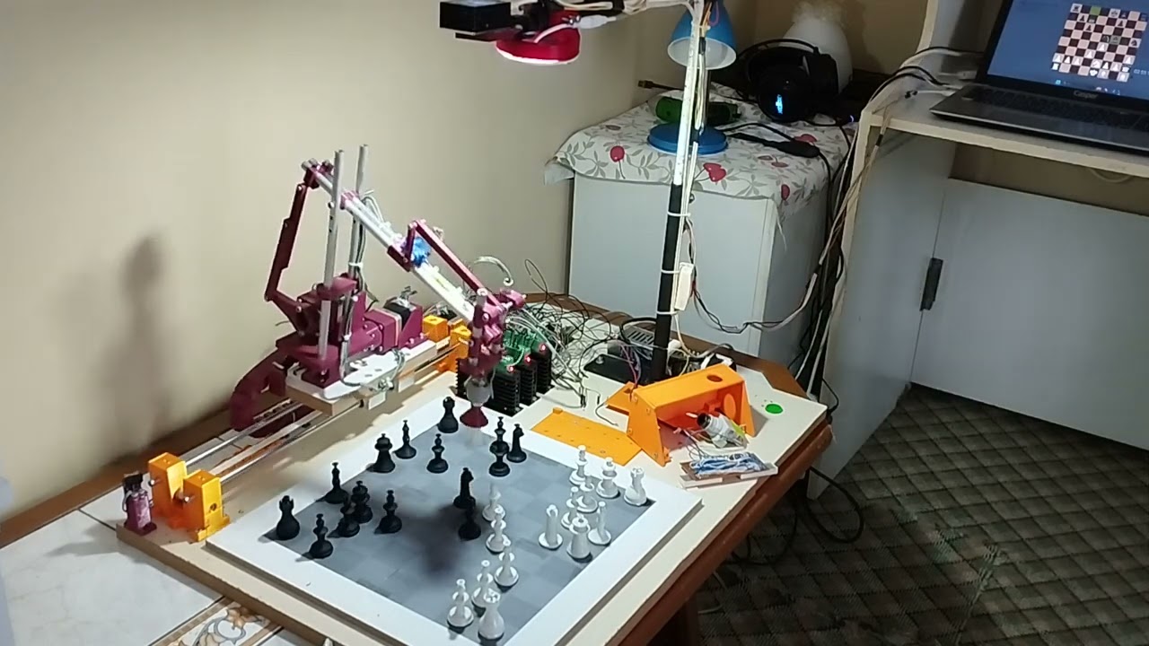

GitHub
Contribute to KeremCikikci/roboChess development by creating an account on GitHub.
 valid sail
how I can disable the bootloader for a Raspberry Pi Pico?
Pls, I cant save and exceute programs on Thonny if I dont disable it
Any help is appreciated
valid sail

 vivid shadow
yall, i need some help, on arduino uno r3 i want to controll a servo with a pot (potentiometer) and record all of it and play it back later, without a sd card module, i have no code, nor do i know how to code, i understand the arduino unos sweep servo example, any help is highly appreciated as i am a beginner with the slightest sliver of knowledge
errant shell
vivid shadow
yall, i need some help, on arduino uno r3 i want to controll a servo with a pot ...
Since you need to store data, on your computer, and are using simple peripherals (analog in plus servo out), I would recommend using a stock Arduino firmware like Firmata. Then you can do all the programming on your computer, in regular Python with pyfirmata library. This is considerably easier than writing Arduino C++ plus a combination of host Python to do the storage
vivid shadow
have a link for the things?
hallow igloo
For rp2040, pico, in T-pico c3
What's the best IDE?
I'm very new with micropython
And thinking should I stick with c or Try to dabble in micropython
elfin sphinx
unless you want to squeeze out all the performance out of your rp2040 , micropython is just fine
for IDE , i like thonny
 ashen widget
How to write to ESP32
elfin sphinx
in many ways
most popular are arduino framework, esp-idf , micropython , circuitpython
errant shell
vivid shadow
have a link for the things?

GitHub
Turn your Arduino into a realtime data acquisition card under Python - GitHub - berndporr/pyFirmata2: Turn your Arduino into a realtime data acquisition card under Python
limber field
ohh looky looky , whats this ...
limber field
neat stuff @errant shell
 midnight sluice
 cerulean crag
ive never used my arduino UNO R3 before but can someone tell me how I could run an API request to the cryptocompare website every 5 mins and save in a CSV file? I did it on my computer but I don't know if I can run python on a Uno r3
 tough stone
Can someone help me in #databases because it is a code that is running in a docker container on a raspberry pi
errant shell
cerulean crag
ive never used my arduino UNO R3 before but can someone tell me how I could run ...
You cannot run Python on your Uno r3. If you want to save things on your computer, just run it on the computer. Get a Raspberry PI or rent a virtual private server if you want to run it somewhere independent.
elfin sphinx
rpi 4-5 might be overkill for this tbh
get a zero 2 w at max (if its just a simple get API request)
tough stone
i have the 4 at home and i'm running some sites and some school projects
covert ore
Hey everyone! it's me again with another question!
So I've made 3 programs, but now I need a main program to acces them all. My question for you guys is how do I acces another program from another one?
 pearl tree
covert ore
Hey everyone! it's me again with another question!
So I've made 3 programs, but ...
pearl tree
covert ore
Hey everyone! it's me again with another question!
So I've made 3 programs, but ...
If they’re all python files, you can most likely import the smaller programs inside the “main” program and run it
Anyone got quick and fun project ideas using a microcontroller?
elfin sphinx
pearl tree
Anyone got quick and fun project ideas using a microcontroller?
a DIY macropad
you can use circuitpython along with a rpi pico
pearl tree
What’s a macropad?
elfin sphinx
pearl tree
What’s a macropad?
smth like streamdeck
basically buttons like keyboard that do a preconfigured action on a pc
for example - pressing a button to open chrome tab with a website in it , or opening all the apps that your dev env needs with 1 button
basically combining multiple keystrokes in one key
pearl tree
elfin sphinx
smth like streamdeck
basically buttons like keyboard that do a preconfigured ac...
Oo that sounds interesting. Ty for the idea
limber field
i only have Rpi3B+ and a PinaeA64 ( 2 Gig ) , im guessing RPi4 / 5 its much better @tough stone ]
limber field
i seen that name , dont really know what it is
virtual layer ?
dockers containers hmmm @tough stone
tough stone
Just that not everything is installed on my pi. When i remove the docker everything else from that program will be removed
thinkt to an python program with a lot of packages.
limber field
sandbox layer ?
limber field
well i have installed stuff that ruined my OS install before , maybe i need this stuff when experimenting
tough stone
just go to hub.docker.com
limber field
can you create a virtual CPU or MCU in it
tough stone
there are a lot of prebuilds that you can use
tough stone
limber field
can you create a virtual CPU or MCU in it
i don't think it
you need to look it yourself
limber field
mmm ok i will , did you also use VMware ?
tough stone
yes but that is on my windows laptop
limber field
i havent tested a virtual layer - for OS experimenting , upstairs machine has 8 Gig , downstairs machine has 16 Gig , im guess virtual needs tons of memory ?
tough stone
when you use docker it is the same as you run it directly to the machine
limber field
speed optomized to the environment ?
limber field
mini servers on Pi
tough stone
you can call it like that. It are dockers
tough stone
but at this moment i'm colling my pi with a big fan and it is just 30°c
limber field
i did some basic , python to read CPU temp of RPi3B+ , i need to make enclosure
was going to use serial on GPIO OR USB-->SER to MCU
i need to expand my projects
 errant stone
I've not used micropython before but I have to for a project.
I have a function that gets called, then a delay for an arbitrary amount of time, then gets called again, etc. This sometimes needs to be reset and the delay canceled.
In C I would do this in the main loop with a state machine where it gets the current time in milliseconds and, if the current time >= next_call_time, calls the function. It then sets next_call_time to now+delay.
However, MP has asyncio built in. Which is neat. But I plan on pushing this controller to do as much as possible, so efficiency matters.
What's the overhead for asyncio vs a while(true) in main() that checks the time as described above?
 spiral sandal
errant stone
I've not used micropython before but I have to for a project.
I have a function...
spiral sandal
errant stone
I've not used micropython before but I have to for a project.
I have a function...
well "out of the box" scheduling is far from ideal. To get soft real time it needs a bit more plumbing than just asyncio. really no generic answer, it is per use case
errant stone
Accuracy isn't super important, I'm more concerned about memory since that is always in short supply
spiral sandal
just use a psram enabled board
errant stone
Not my decision to make 😦
spiral sandal
if you are not time critical it is quite easy to handle memory with context manager and modules + manual GC
but it is not related to strictly asyncio
also i think i saw something about running bytecode from rodata only
 zenith niche
I'm trying to follow this advice on using this to control an ESP32 with a regular .py running on another device and I'm confused about how to use Telemetrix4ESP32...
I've installed the client in the venv where I intend to run the .py with pip install telemetrix-esp32
And now I need to install the server component on the ESP32, correct? But I'm using PlatformIO, and this only lists instructions for Arduino IDE https://mryslab.github.io/telemetrix-esp32/server/ . How can I get this going with PlatformIO within VS Code?
Am I approaching this in the right way?
spiral sandal
zenith niche
I'm trying to follow this advice on using this to control an ESP32 with a regula...
for the esp32 io part here's what i used ```
[env:esp32cam]
platform = espressif32
board = esp32cam
board_build.mcu = esp32
board_build.f_cpu = 240000000L
framework = arduino
lib_deps =
mryslab/Telemetrix4Esp32
robtillaart/DHTStable@^1.1.1
arduino-libraries/Servo@^1.2.1
you need to adapt for your board but there is documenation around
zenith niche
spiral sandal
for the esp32 io part here's what i used ```
[env:esp32cam]
platform = espressif...
ooh beautiful ok ty. so these are the settings you've listed in the platformio.ini?
should I add this to mine?
lib_deps =
mryslab/Telemetrix4Esp32
which would make mine:
[env:esp32dev]
platform = espressif32
board = esp32dev
framework = arduino
upload_port = /dev/ttyUSB0
lib_deps = mryslab/Telemetrix4Esp32
does that look right?
spiral sandal
looks legit, but you still need the dht/servo stuff if lib manager won't add them
they are telemetrix deps
zenith niche
ok awesome! soooo what happens now? lol
how can I write a py to connect to this server which will assumedly now run on the esp32?
spiral sandal
i used telemetrix aio module, for both native and web ( pygbag / pyscript )
zenith niche
spiral sandal
i used telemetrix aio module, for both native and web ( pygbag / pyscript )
sorry, I don't understand what this means. Could you please elaborate?
spiral sandal
i don't have more than that to quick share https://github.com/pygame-web/showroom/blob/main/src/test_telemetrix.py
here's the wheel just in case https://github.com/pygame-web/archives/blob/main/repo/pkg/telemetrix_aio-1.11-py3-none-any.whl
in any case you want to drive a poppy arm i have the 3d model rigged for harfang
zenith niche
spiral sandal
here's the wheel just in case https://github.com/pygame-web/archives/blob/main/r...
I'm sorry dude I'm not very good at this and I don't understand this or the relevance of it 😅
just looking for the simplest possible way for a .py to tell an ESP32 via wifi to turn a relay on / off
spiral sandal
zenith niche
I'm sorry dude I'm not very good at this and I don't understand this or the rele...
then just look at the "blink" part for the test 😄
and ignore the stepper motors stuff 🙂
good luck !
zenith niche
spiral sandal
then just look at the "blink" part for the test 😄
OK! I've taken the "blink" part of your script and other stuff I thought might be necessary and have tried to simplify as much as possible! Have drafted this:
import asyncio
from telemetrix_aio import telemetrix_aio
import sys

# some globals
DIGITAL_PIN = 2  # arduino pin number

async def blink(board, pin):

    # set the pin mode
    await board.set_pin_mode_digital_output(pin)

    # toggle the pin 4 times and exit
    for x in range(2):
        print('ON')
        await board.digital_write(pin, 0)
        await asyncio.sleep(.5)
        print('OFF')
        await board.digital_write(pin, 1)
        await asyncio.sleep(.5)

# the IP address of the ESP32
ip_addr = '192.168.88.237'

async def main():
    global ip_addr
    if sys.platform in ('emscripten',):
        window.MM.set_socket("ws://") # what's this window thing from?
        print(f"Board (Web)socket : {ip_addr}:31335")
    else:
        print(f"Board socket : {ip_addr}:31335")

    board = telemetrix_aio.TelemetrixAIO(ip_address=ip_addr, autostart=False)

    await board.start_aio()

    await blink(board, DIGITAL_PIN)

asyncio.run( main() )
it's throwing the error that it "Can't open connection to 192.168.88.237". Does this .py look right? Is there something I need to configure in the ESP32?
this is where the ESP32 "main.cpp" is
#include <Arduino.h>
#include <WiFi.h>

// network credentials
const char *ssid = "homenwname";
const char *password = "homenwpw";

void setup()
{
    Serial.begin(9600);

    WiFi.mode(WIFI_STA);
    WiFi.disconnect();

    // WiFi.mode(WIFI_STA);
    WiFi.begin(ssid, password);
    Serial.println("\nConnecting to WiFi Network ..");

    while (WiFi.status() != WL_CONNECTED)
    {
        Serial.print(".");
        delay(100);
    }

    Serial.println("\nConnected to the WiFi network");
    Serial.print("Local ESP32 IP: ");
    Serial.println(WiFi.localIP());
}

void loop()
{
}
Does this look right? Is there something I should include at the top here?
spiral sandal
your loop is empty try something like ```C++
void
loop() {
client = wifiServer.available();
if (client) {
    Serial.print("Client Connected to address: ");
    Serial.println(client.remoteIP());

    while (client.connected()) {
        // if (client.available())
        {
            delay(1);
            {
                // keep processing incoming commands
                get_next_command();

                if (!stop_reports) {        // stop reporting
                    if (can_scan) {
                        scan_digital_inputs();
                        scan_analog_inputs();
                        scan_sonars();
                        scan_dhts();
                        scan_touch();
                        run_steppers();
                    }
                }
            }
        }
    }
    client.stop();
    Serial.println("Client disconnected");
}
}
wifiServer.begin(); goes into setup
spiral sandal
zenith niche
this is where the ESP32 "main.cpp" is
```
#include <Arduino.h>
#include <WiFi.h>...
there should be that sample somewhere in telemetrix esp32 repo i did not invent it
or maybe copied it from esp8266
zenith niche
spiral sandal
there should be that sample somewhere in telemetrix esp32 repo i did not invent ...
yeah I'm real confused cause I don't see any .cpp examples in the telemetrix docs https://mryslab.github.io/telemetrix-esp32/api/
super dumb question: is the .cpp extension code c++? are we coding in c++ here?
spiral sandal
arduino is c++ framework
spiral sandal
zenith niche
yeah I'm real confused cause I don't see any .cpp examples in the telemetrix doc...
zenith niche
spiral sandal
.ino == .cpp it is here https://github.com/MrYsLab/Telemetrix4Esp32/blob/master/...
cool! ok so am I to include the entirety of this? or should I be putting in something like #include <Telemetrix> at the top of the .cpp?
thanks for all your help and patience dude. I feel like a total idiot 😅
errant stone
Is there a better way to test micropython projects? Constantly uploading scripts to my 8266 takes a lot of time when I just need to see how one thing works
spiral sandal
errant stone
Is there a better way to test micropython projects? Constantly uploading scripts...
why do you upload them then, the board can download them and run them
you are wearing your flash and losing time, wifi download is faster than serial flash
errant stone
because I don't know how to do that. I've been using Thonny and uploading stuff to the board
spiral sandal
you don't need much, python -m http.server pc side, urllib.urequest + exec() board side in your boot.py
and eg download from the pc a 192.168.x.x.py file that match board assigned wifi IP
edit file / save / push reset => enjoy
errant stone
I have 5 different .py files in this project. Is that not normal for micropython? Should I combine them into one giant file? I'm used to compiled languages where that never matters.
spiral sandal
errant stone
I have 5 different .py files in this project. Is that not normal for micropython...
on esp8266 the best is smaller modules in .mpy bytecode format
and a context manager to load/unload module for use
to regain memory right after module use
errant stone
I've been using mpy_cross to convert to mpy before uploading, it saves a ton of space
spiral sandal
indeed
 neon swift
Is there a relay controller python module for use with raspi that has a web interface and handles 8 or more channels, that non-technical people can use to set timing on the relays? We need a better water pump timer solution for our massive collection of lizards and the proprietary pump controllers are NOT cutting it.
spiral sandal
neon swift
Is there a relay controller python module for use with raspi that has a web inte...
not strictly python but has all you will ever want and really FOSS https://github.com/pilight/
 errant stone
@spiral sandal Buried in the docs for MP is mpremote, which isn't terribly interesting imo except it has a mount subcommand that basically mounts a local directory on the board and opens a python shell so all I have to do is import main
https://docs.micropython.org/en/latest/reference/mpremote.html#mpremote-command-mount
It works incredibly well and I can even my http server stuff (html, js, etc) with zero effort
spiral sandal
errant stone
<@334096250897170433> Buried in the docs for MP is `mpremote`, which isn't terri...
still need the wire no ?
doc of that module speaks of /dev/tty*
i thought everybody knew https://github.com/scientifichackers/ampy already 🙂

GitHub
MicroPython Tool - Utility to interact with a MicroPython board over a serial connection. - GitHub - scientifichackers/ampy: MicroPython Tool - Utility to interact with a MicroPython board over a s...
errant stone
spiral sandal
still need the wire no ?
Yeah, its over usb, but i'm ok with that
spiral sandal
well minimal boards don't have usb to serial
so better have a tool around that can use wifi only
 formal summit
I need help in Arduino, can anyone?
elfin sphinx
formal summit
I need help in Arduino, can anyone?
just ask your question , dont ask if anyone is there to help or not
provide full problem , ckt diagram , code, what you want to happen and what actually happens
 flint zephyr
Question for the group… is there any advantageous reason to use micropython when programming Arduino?
Through Python I got into the idea of microcontrollers, but I’m familiar and comfortable with C / C++ . Does it not matter at compile time? Has anyone explored the difference (if any) between using micropython and C?
Also (side question) any recommendations on IDE? So far I’ve been using the Arduino 2, but saw VSCode options etc… thanks!!!
spiral sandal
flint zephyr
Question for the group… is there any advantageous reason to use micropython whe...
it is easier to write coroutines iter/gen or async/await in python than C/C++
imho a good in beetween to python/C for embedded would be Nim-lang
platform.io supports well arduino, and Eric ide support well micropython
flint zephyr
spiral sandal
it is easier to write coroutines iter/gen or async/await in python than C/C++
Thanks! I’ll also check out Nim-lang (never heard of that). I’m definitely fine with learning new stuff! I know that although there are many paths, there may be some paths better than others haha!
So far I’m just mucking around, but have a goal to mess around with making some audio related stuff (I’ve made some simple FX pedals in the past, and messed around with some analog stuff, but nothing with a micro controller involved).
errant stone
What's a good http server? I tried nanoweb because it is very small, but I keep getting Connection Reset errors when I shouldn't. https://github.com/hugokernel/micropython-nanoweb

GitHub
Full async Micropython web server with small memory footprint. - GitHub - hugokernel/micropython-nanoweb: Full async Micropython web server with small memory footprint.
spiral sandal
errant stone
What's a good http server? I tried nanoweb because it is very small, but I keep ...
judging good would need serious code audit, so i guess you should just try them all 😄
also on what chip are you running that ?
errant stone
I'm using an 8266. I'm really confused about what is happening because when I serve a file it works fine, but returning just a status eg HTTP/1.1 400 Bad Request causes the Connection Reset error.
I'm probably not understanding how the internet works, but I've done a few webuis with different backends and never ran into this so idk
errant stone
The examples in the repo were 0.9, but that didn't work either and had the same connection reset error. I'm not a web guy but I've done a few backends in rust and cherrypy a long time ago and it was so much easier lol
torpid verge
errant stone
What's a good http server? I tried nanoweb because it is very small, but I keep ...
Microdot is up to date, works with asyncio and https. Had a good experience using that
torpid verge
flint zephyr
Question for the group… is there any advantageous reason to use micropython whe...
Vscode has stubs for micropython, use mpremote for communication with the microcontroller. Thonny is also popular. Having used both C and Micropython for microcontrollers, I prefer Micropython, I need much less time to get to a result.
errant stone
torpid verge
Microdot is up to date, works with asyncio and https. Had a good experience usin...
Microdot gives me mem allocation errors, which means it is probably designed to run on an 8266 without leaving room for anything else.
spiral sandal
errant stone
Microdot gives me mem allocation errors, which means it is probably designed to ...
tbh handling 8266 low mem requires some python wizardry. an esp32+psram is way easier to handler for newcomer
errant stone
I think I may have found the origin of my problem, and it is in the asyncio library so it would likely affect all micropython async http servers.
I was sending a POST that could contain a fair amount of data. Before I did anything with this data I wanted to verify it by checking the first 4 bytes to match against a known file header. Then if it isn't the right kind of file I could stop immediately.
If I send a curl -X POST -d "abcd" 0.0.0.0/test it would send the response as one would expect (either a 200 or 415 depending on if 'abcd' is what I wanted to read).
But If I send curl -X POST -d "abcde" 0.0.0.0/test I will get a Connection Reset error. Regardless of what response I send it would always reset.
It seems that reading from the request stream and leaving any data unread causes problems. If I read all of the bytes being send it responds normally. But that defeats the purpose of filtering out bad uploads in the first place.
So Nanoweb works fine as far as I can tell, its the underlying asyncio streams that are being cantankerous.
spiral sandal
there's an asyncio channel on micropython's discord
limber field
if you have a tkinter GUI loop and need to have extra processes , say a text to speech , is asyncio for this purpose OR another module better ?
@spiral sandal
errant wigeon
limber field
if you have a tkinter GUI loop and need to have extra processes , say a text to...
This probably isn't a question for micro controllers. As far as I'm aware there isn't a port of tkinter GUI for micropython or circuit python. You might get a better answer in #user-interfaces
limber field
i use tkinter as a virtual control panel via pyserial to a MCU , bi-directional messaging
have you used the asyncio module for anything ? I use a multicore MCU @errant wigeon
errant wigeon
No I don't have a usecase where it is beneficial
Can you provide more detail on your setup? Under the current setup it still sounds like the host of tkinter is a computer rather than a micro controller
What kind of micro controller are you using, are you using circuit python, micro python, pyfirmata, or something else on it, can you share a sample of your code? that kind of thing would be very helpful
spiral sandal
limber field
if you have a tkinter GUI loop and need to have extra processes , say a text to...
if on esp8266 you don't have other (good) choice, asyncio is the way
btw instead of tkinter (eg on android) there's https://github.com/ArminJo/Arduino-BlueDisplay which comes in handy
you are in the microcontroller channel
 ocean tapir
 velvet cosmos
Might be a weird Q but is there a mechanism in Micropython by which I can programmatically define constants at freeze-time? I need to generate hundreds of different firmware images with different string constants. (For ESP32 if it's relevant)
const() doc gives examples like bitwise operation between two other constants but my usecase is more complicated.
I basically need to compute a random number and plug it into a table, then freeze that string in the image.
errant wigeon
constants at freeze-time
I don't quite know what you mean by this. Could you provide more information about what you mean by freezing the string in the image? What image specifically, like the deployed micropython build for each controller?
velvet cosmos
errant wigeon
> constants at freeze-time
I don't quite know what you mean by this. Could you p...
so micropython supports precompiling modules to bytecode and embedding this into the micropython firmware. Once you flash that image to the microcontroller, the micropython interpreter can use your bytecode without having to retrieve it from the filesystem.
It seems like the tooling for this all wants source code though. I was hoping there'd be some cool middleware where you can programmatically change parts of the output.
errant wigeon
are you referring to the .mpy files
or the more 'core' micropython code? (which I believe is written in c)
velvet cosmos
Neither. Mpy files can be frozen too though seems like
From further reading seems like the relevant process is the bytecode generation itself though, not the freezing.
errant wigeon
Huh I've never had cause to use this. I was completely thinking the .mpy files and only through that lens
I don't know the answer, but maybe someone else does.
And in case that person isn't on this server, the micropython server is awesome: https://discord.gg/RB8HZSAExQ
errant wigeon
velvet cosmos
From further reading seems like the relevant process is the bytecode generation ...
yeah the bytecode, mpy files, frozen stuff, and memory stack allocation is a weird thing. It's a lot, and a whole lot of low level optimizations for a hyper specific use case
velvet cosmos
essentially what I want to do is generate a bunch of strings on my development computer, and make them into constants in the bytecode.
errant wigeon
Kind of like a security key application?
velvet cosmos
That's not my usecase, but the process would be essentially the same yeah.
errant wigeon
cool, even if it's not your use case, it's a use case that has lots of folks who've tried it and if it's similar enough that might help you get an answer faster
velvet cosmos
I only mention it because normally I would probably just put the keys directly in the filesystem or a dedicated partition
errant wigeon
Yup I get that. I just don't know the solution at that level of micropython, and know folks on the other server probably do
spiral sandal
velvet cosmos
essentially what I want to do is generate a bunch of strings on my development c...
for that you add them to qstrdefsport.h and rebuild mpy-cross and the port
that subject has keywords "qstr and string interning"
i still think upy should provide an option for uinterned strings , eg with syntax u"text" which is not used anymore but is valid python. nb i already suggested that when f-strings parser was about to be integrated
 keen berry
Hello! I was wondering if anyone got into electronics(I'm talking about the one that is closer to the academic world) from a math and computer science background. Since I didn't have the opportunity to take physics in high school I can't go for electronics as my main course. I was wondering whether it'd be a good idea to go with math and computer science as a dual course and I could take additional courses on electronics as I go. Has anyone done something similar, or what do you think?
elfin sphinx
depends on what you mean by electronics here
EE has a lot of stuff going on other than embedded stuff only
if you want to learn core stuff, i doubt you will have time to pursue that alongside a dual degree program
(btw not knowing physics is not a big obstacle for electronics world) ,you mostly learn the stuff as you go (as long as you know basics , you are fine)
but EE is heavy on math for sure
keen berry
Yes, but it is part of the entry requirements. And I unfortunately can't take physics in high school.
keen berry
elfin sphinx
depends on what you mean by *electronics* here
EE has a lot of stuff going on o...
Hmm not sure then.
elfin sphinx
you can learn the embedded stuff only tho
like without pursuing the whole EE syllabus
if embedded is the only thing you really care about
elfin sphinx
keen berry
Hmm not sure then.
what exactly is it that you want to achieve from doing the EE stuff ?
keen berry
elfin sphinx
what exactly is it that you want to achieve from doing the EE stuff ?
I'm interested in CPU and low-level hardware design.
elfin sphinx
oof , for lower level CPU hardware design , a deep understanding of EE is a must
keen berry
But can't take it because of the lack of physics.
elfin sphinx
tbh , physics is not that important
most important thing is maths
keen berry
So I could go with math and computer science while attending additional courses on ee
keen berry
elfin sphinx
tbh , physics is not that important
most important thing is maths
Yes but I don't think I have much chance without doing physics in high school.
elfin sphinx
keen berry
So I could go with math and computer science while attending additional courses ...
you can try , but there is just loads of stuff to learn
stuff like network theory , analog electronics , digital electronics, Electronic devices and such is the bare minimum
elfin sphinx
keen berry
Yes but I don't think I have much chance without doing physics in high school.
it is possible that what you think might not be the case , right ?
keen berry
elfin sphinx
it is possible that what you think might not be the case , right ?
Well, not sure in the UK it kinda matters I believe. Based on the unis websites.
elfin sphinx
it may matter academically Like to get through a screening process or being eligible
but in reality , it is used very little
keen berry
What do you recommend then?
If I got in with maths and computer science I might be able to change it later.
elfin sphinx
you can try ECE , which is electronics and computer engineering ?
just wondering how they give you admission for CS but not EE branches based on a single subject
keen berry
The problem is that in the entry requirements, they point out that physics is needed. Not sure what that means in reality.
elfin sphinx
if there is absolutely no way in hell that you can do EE via the college route , then sure , you can learn two things at once
but i am not really sure if you will get good at both tbh (you can either get good at EE and do the bare minimum in CS or vice versa)
to be fair , you can put low emphasis on subjects like EMFT and such if you want to get into CPU design
keen berry
Did you do electronics in uni?
elfin sphinx
but i am not sure you will find jobs in core fields easily since you will get a degree in CS
elfin sphinx
keen berry
Did you do electronics in uni?
yep
keen berry
Did you take physics in high school?
elfin sphinx
yep
but to be fair , we here have same requirement for most engineering streams , and physics is required for all of them
keen berry
That is what I'm talking about.
elfin sphinx
so it doesnt make sense to me that they reject you for EE but are ok for CS
keen berry
They are required.
elfin sphinx
if its for all the streams , then sure
why discrimination is my point lol
keen berry
elfin sphinx
so it doesnt make sense to me that they reject you for EE but are ok for CS
They didn't I'm in grade 11
elfin sphinx
have you inquired about it with them ? maybe its not really a rquirement , but a good to have ?
 elfin sphinx
keen berry
Look at the entry requirements this is just an example.
elfin sphinx
keen berry
Look at the entry requirements this is just an example.
one of Physics (preferred) Biology, Chemistry, Computing Science or Engineering Science at B
it looks to me you have to choose 1 from all of these , physics is just an option , not a requirement
keen berry
elfin sphinx
> one of Physics (preferred) Biology, Chemistry, Computing Science or Engineerin...
Okay I can't take any of those either.
elfin sphinx
those look pretty standard to me tbh , not sure how you dont meet those requirements
but you can try looking for other UNIs as well and see if they have some looser requirements
elfin sphinx
what i am trying to say here is
if you wanna do EE, you should do it as a uni course and not a side thing because getting job in core field without a degree in EE related field is tough
but if EE is not your main focus and you just want to do it as a good to have , then sure , take complimentry courses and leaern what you like
keen berry
Alright, I will see what I can do.
elfin sphinx
and i highly doubt that you will be able to do 2 full 4 year uni courses simulteneously
so lets just get that picture out of the mind 😅
👍
keen berry
Thank you for your time.
elfin sphinx
youre welcome 👍
cloud hinge
Bridging solder on perf boards or bridging jumper bars, what do u prefer and is there any better methods? I found solder blob joints a bit easier but they tend to blob on the other side of perfboard, maybe i was doing something wrong.. each method i had blobs hitting each other alot, seemed the jumpers were much more finiky. Maybe i should just use wires next time instead of the bars. Any and all insight is much apprecieted

 elfin sphinx
i either use a copper wire or i just take one simple jumper or whatever thin enough wire lying around , strip its insualtion off completely , then tin the wire
and then i just solder it between the points (where your solder blob would have gone , it makes the whole process insanely easier and uses less solder too
cloud hinge
elfin sphinx
i either use a copper wire or i just take one simple jumper or whatever thin eno...
Makes perfect sense, thank you for the valuable insight
I realize now i did not tin jumpers first.🤣 Coppers easier im guessing
elfin sphinx
tbh i have used bare copper wire very few times , and it was easy
but i mostly just do the stripping wire off thing 😅
and yeah , if the wires are not pre tinned ,it makes it a tad bit more difficult
the beneifit of having them pre tinned is that , you can just stick the wire to given point on PCB by just momentarily touching the iron to the wire
so , the solder on the wire gets melted and wire attaches to the PCB
you can make some good wire bends with practice
 elfin granite
how does circuitpython manage to create a virtual hard disk
like what library does it use
 runic ridge
Gonna attempt to make a binary addition circuit using just a bunch of AND and XOR gates from the 74LS08 and 74LS86 chips. anyone have experience with those?
errant wigeon
elfin granite
how does circuitpython manage to create a virtual hard disk
Most of Circuit Python runs on devices with Native USB which lets it use "TinyUSB", a c package they include with building circuit python for the specific hardware. TinyUSB lets it emulate hardware as if it were a traditional USB device. It's pretty neat, but it get's really complex. Here's the source: https://github.com/hathach/tinyusb
elfin granite
errant wigeon
Most of Circuit Python runs on devices with Native USB which lets it use "TinyUS...
thank you
errant wigeon
runic ridge
Gonna attempt to make a binary addition circuit using just a bunch of AND and XO...
I don't have recent experience with that but it's a traditional enough project that is pretty fun
runic ridge
errant wigeon
I don't have recent experience with that but it's a traditional enough project t...
🙂
i eventually want to make a whole computer but I'm a far ways away from that
why do a lot of computers use a ton of relays instead of the logic gates like inside chips like the 7400 series?
errant wigeon
Ben Eater's youtube channel is the place to go for that: https://www.youtube.com/playlist?list=PLowKtXNTBypGqImE405J2565dvjafglHU
What do you mean a ton of relays?
runic ridge
errant wigeon
Ben Eater's youtube channel is the place to go for that: https://www.youtube.com...
Thanks! been watching his vids a little bit and enjoying them. I'm talking about projects like this: https://www.youtube.com/watch?v=e8DavnWmr1E. Is it just to be old fashioned? Is there any benefit/difference to using relays vs logic gates?
I know that you can create logic gates from relays but I just don't get the point
all of my knowledge of computers has been learned recently from nandgames lol
errant wigeon
Ah, this isn't an example of a modern computer, or a modern computer build. It's much more of a challenge and a way to physically view and understand what a transistor is doing in a circuit--a lot of times folks will say, "A transistor is like a little switch", so since relays can act as switches, it looks like this guy took that idea to a limit
runic ridge
errant wigeon
Ah, this isn't an example of a modern computer, or a modern computer build. It's...
is it right to say to build a computer you need to build logic gates out of transistors or relays?
and if so that brings me back to the question why not just use the logic gates like on the 7400 chips?
errant wigeon
Ehh that's not a thing I'm really great with. Technically a "computer" is a device that replaced human computers--folks who were employed to do a ton of math. So yes, computers need logic gates of some form. But you also need power supply, memory, user interface, etc.
Some chips, (7400's maybe) are power hungry and a smaller package than they provide is better. But, if you want to see the parts of the computer that are doing each step of logic, 7400's are fantastic. You get to engage with a computer at that level which is harder with modern systems on chips which have it all baked into a tiny, tiny space
runic ridge
errant wigeon
Ehh that's not a thing I'm really great with. Technically a "computer" is a devi...
thank you for the thoughtful answer!
errant wigeon
No problem, ben's series goes into a ton of more detail on a lot of those questions. I cannot recommend it enough!
runic ridge
errant wigeon
No problem, ben's series goes into a ton of more detail on a lot of those questi...
can't wait to get deeper into it :0
 mystic jasper
When using the arduino as an ISP and using the hardware SPI, can the VCC and GND pins of the hardware spi be expected to power the circuit as well?
mystic jasper
I mean the VCC and GND here, not 5V on the female headers
 mystic jasper
Everyone suggests using pin 13-10 rather than this ICSP header, I wonder why?
 gray arch
Hello everyone, I would like to start tread where we can discus some aspects of Computer Vision.
-
I'm interesting entry point in this area
-
If i would like make autonomous small device lets call it "Drone"
-
How powerfull my hardware has to be to handle realtime data processing. and what i need for that.
3.1. Camera
3.2. GPS*
3.3. IMU
3.4 Distance sensor
3.5. Onboard Computer -
Technology stack for software. ( Open CV, CNNs TensorFlow etc, python, C,) - I'm confused with this moment as i cant understand what hardware i need to handle Open CV and CNNs on autonomus board)
-
gps denied, gsm-less, fully autonomus.
I'm very new for this topic and want get basic imagination what to expect
mystic jasper
mystic jasper
When using the arduino as an ISP and using the hardware SPI, can the VCC and GND...
oh well the power-rails on my breadboard had a break in them (this is the only one with a break, everything else was connected all the way through :/) which led to me not having 5V on the other side where I had my circuit setup, what an annoyance
 graceful imp
I had one too no way
velvet cosmos
runic ridge
is it right to say to build a computer you need to build logic gates out of tran...
 runic ridge
velvet cosmos
https://xkcd.com/505/
runic ridge
velvet cosmos
https://xkcd.com/505/
Fire
I wonder how logic gates would work as rocks tho
Ig in this comic the guy is doing all the logic gates manually, there’s nothing special about a rock that could do it
velvet cosmos
He's basically using them as bits directly. Rock in low position = 0, rock in high position = 1
His body is the logic gates
runic ridge
velvet cosmos
His body is the logic gates
Ye in that case he’s also the computer
The rocks is just info 😛
 onyx river
.
errant shell
gray arch
Hello everyone, I would like to start tread where we can discus some aspects of ...
In general if you want to hate capacity and flexibility to do computer vision, go for a Single Board Computer. Like a Raspberry PI 4+ or even a Jetson NANO, depending on what kind of frame sizes / framerates and neural networks you want to run.
hallow igloo
i dunno if this is the right place, but i need this micropython to be decompiled.
https://paste.pythondiscord.com/L3MQ
 maiden island
hi
i need help
in raspberry pi3 B+
when I boot up the os the screen goa's blue in beetwen
pls help me
 wet prism
smoky meadow
wet prism
smoky meadow
Asked if my rpi game was good the said it was nice but a little thin so will make a sum out of it Just to add stuff and pass ig  😆
😆
 spring willow
Hello!
I’m thinking a lot about making a game panel, and I need some help to choose which microcontroller I am gonna use.
I want to send inputs from the microcontroller, if possible without any extra software on the PC, if that’s possible?
Can a PC recognize any such inputs?
spring willow
Will ESP32 do the job?
elfin sphinx
wired or wireless ?
spring willow
elfin sphinx
wired or wireless ?
Wired 👍
elfin sphinx
spring willow
Wired 👍
then you have lots of options , to run it without additional software , you basically just need to configure it as a USB HID device , which is totally possible
basically any microcontroller with native USB host support should work
my faviourite option is raspberry pi pico , it is cheap , has native USB support and supports micropython / circuitpython which has built in libraries for USB communication stuff
ESP32 S2 also supports native USB afaik , but i have not used it
even an arduino pro micro (board with 32u4 processor) also supports it
spring willow
elfin sphinx
then you have lots of options , to run it without additional software , you basi...
Alright, thanks for the info! Do you think the controllers from Temu are any good?
Worth mentioning is also that I want to light some lights up, that’s possible too right?
As you might figure I don’t know much
elfin sphinx
spring willow
Alright, thanks for the info! Do you think the controllers from Temu are any goo...
I am not sure since i dont have any experience with temu 😅
elfin sphinx
spring willow
Worth mentioning is also that I want to light some lights up, that’s possible to...
on the control unit you are gonna make with the microcontroller , right ?
yeah , that should be possible 👍
spring willow
Alright! Well yea well I have buttons with built in lights, that I want to be lit when pressed
I’m thinking just that and the microcontroller
Connected via usb
spring willow
elfin sphinx
on the control unit you are gonna make with the microcontroller , right ?
yeah ...
Yea well I’ll code it to make the lights light up when pressed and get off when pressed again
And send an input to the PC
elfin sphinx
yeah , that is doable 👍
some switches may even have a built in LED that will be hardwired so that it turns on and off automatically
spring willow
elfin sphinx
yeah , that is doable 👍
some switches may even have a built in LED that will ...
Oh wow, didn’t know that! Will I need to solder the pins?
elfin sphinx
yes , for sturdy connections of components , soldering is recommanded
you can however use solderless breadboards for prototyping
spring willow
I’ll order an ESP32 S2
 last chasm
this is reking me
would anyone mind helping here?

I've got temp working but can't humidity working


I've been trying to restructure the forumlas to wokr with my var names and whatnot
 mighty mountain
How can i incorporate a python library/package to my arduino. I have want to use python to translate some text into braille, and then send that to the arduino, and make it light some LEDs according to the data. I want to use this package https://github.com/ant0nisk/pybrl
GitHub
An Open-Source Grade-2 Braille Translation system written entirely in Python - GitHub - ant0nisk/pybrl: An Open-Source Grade-2 Braille Translation system written entirely in Python
 onyx glade
Just saw this video, thought it was interesting
https://www.youtube.com/watch?v=-XPrSScamXc&ab_channel=Wokwi

When you write Arduino code, you usually split your code into two parts: the setup() function that runs once, at the beginning of the program, and the loop() function that runs repeatedly. But did you know that it doesn't always have to be this way?
In this video you will learn how to write Arduino code without setup() and loop(), and see some ...
smoky meadow
do i need for a rpi their cable or can i also use a samsung cable?
errant shell
smoky meadow
do i need for a rpi their cable or can i also use a samsung cable?
For powering a RPI via USB? Any decent quality cable will do. They need quite a lot of power though, so any old USB power supply might not be good enough. You will notice if you get the "lighting" symbol on the screen, and these warnings are also logged somewhere
smoky meadow
errant shell
For powering a RPI via USB? Any decent quality cable will do. They need quite a ...
yeah samsung is 15w rpi cabble is 27w so guess will buy 1 of those
 safe smelt
gray arch
Hello everyone, I would like to start tread where we can discus some aspects of ...
safe smelt
gray arch
Hello everyone, I would like to start tread where we can discus some aspects of ...
I just finished a project that used python and OpenCV to do computer vision (image recognition), it was running off a raspberry pi 5 and used two pi cameras. it worked fine in real time. We didn't need to use any artificial nerual networks or machine learning though.
Are you sure you even need to use convolutional neural networks? might be overkill. KISS is a good principle (keep it simple)
if you only need to move a robot around slowly, an arduino should be powerful enough (with C) or raspberry will likely be fine with Python
Query:
is this the discord channel which used to be called smth like "embedded python" ?
I want to learn about running python on an embedded system, without an OS (bare metal - no linux). where can i go to learn more about this - any links?
(oh, i'm reading the pinned messages now...)
hallow igloo
python embedded systems
errant wigeon
safe smelt
Query:
is this the discord channel which used to be called smth like "embedded p...
Did the pinned comments give you enough to point you in the right direction?
limber field
micropython
 zenith heart
is this the appropriate place to ask for circuit python help?
elfin sphinx
zenith heart
is this the appropriate place to ask for circuit python help?
absolutely
 zenith heart
elfin sphinx
absolutely
zenith heart
elfin sphinx
absolutely
Alright, i already posted my problem in python help so here is the link https://discord.com/channels/267624335836053506/1203004945125609582
zenith heart
safe smelt
errant wigeon
Did the pinned comments give you enough to point you in the right direction?
yes, actually. I think i found out about MicroPython from it, and that was most useful/relevant for me. thanks :D
 echo herald
elfin sphinx
echo herald
elfin sphinx
what GPIO pin would what be ?
 crisp solstice
sorry to be vague, how much can an esp8266 really do running micropython
i'd like someone to contextualise for me, as a layman, what sort of complexity you could achieve on these microcontrollers?
just to know whether i should cut my losses and start writing c instead
i have a project to read from multiple sensors, run an lcd display and send data to a sqlserver
limber field
many use C , micro python also
C far more popular from what i have seen @crisp solstice
errant shell
crisp solstice
sorry to be vague, how much can an esp8266 really do running micropython
It is not an either-or. You can combine MicroPython with as much C as you would like. The general recommendation is to start writing everything in MicroPython. If something is too slow, rewrite just that in C (and call it using a module)
Reading say 10 sensors at 100 hz, and updating LCD screen at 30hz, while pushing some kilobytes of data over network a couple of times per second, is no problem
crisp solstice
errant shell
It is not an either-or. You can combine MicroPython with as much C as you would ...
amazing news, much thanks.
 young swift
kk
errant shell
crisp solstice
amazing news, much thanks.
You will probably get very far with just plain (Micro)Python. But just for reference, here are two good talks around optimizing MicroPython, from some of the developers
https://www.youtube.com/watch?v=437CZBnK8vI
https://www.youtube.com/watch?v=hHec4qL00x0
 final oar
Anyone able to help me with installing the libraries to run the code for Raspberry Pi and MLX90640 infrared sensor? I am using windows and I am getting an error when running the code, probably because I've not done things correctly.
https://learn.adafruit.com/adafruit-mlx90640-ir-thermal-camera/python-circuitpython
errant wigeon
final oar
Anyone able to help me with installing the libraries to run the code for Raspber...
What is the error you're getting?
And just to be sure, are you using the windows os option for the raspberry pi, or are you using a traditional windows machine?
final oar
I am using Pi on Wifi, however I don't know how to install the two libraries and googled how to do so but still misunderstood
I am using a winsows laptop
Next you'll need to install the necessary libraries to use the hardware--carefully follow the steps to find and install these libraries from Adafruit's CircuitPython library bundle. Our CircuitPython starter guide has a great page on how to install the library bundle.
You'll need to manually install the necessary libraries from the bundle:
adafruit_mlx90640.mpy
adafruit_bus_device
Before continuing, make sure your board's lib folder has the adafruit_mlx90640.mpy, and adafruit_bus_device files and folders copied over.
I downloaded the bundle folder but don't know how to check my libraries are there and if installed... Usin powershell terminal
It's easier to explain on voice chat but I am surpressed at the moment
errant wigeon
The page is a bit confusing, because there's a lot of ways to do things
For your setup, you'll want to run, sudo pip3 install adafruit-circuitpython-mlx90640 on the pi
actually, I should ask--what kind of raspberry pi are you using?
final oar
PS C:\Users\melis> sudo pip3 install adafruit-circuitpython-mlx90640
sudo : The term 'sudo' is not recognized as the name of a cmdlet, function, script file, or operable program. Check the spelling of the name, or if a path
was included, verify that the path is correct and try again.
At line:1 char:1
- sudo pip3 install adafruit-circuitpython-mlx90640
-
  + CategoryInfo          : ObjectNotFound: (sudo:String) [], CommandNotFoundException
  + FullyQualifiedErrorId : CommandNotFoundException
PS C:\Users\melis>
Also I want to make it clear I'm not fully sure I'm using the terminal right in the first place
errant wigeon
are you typing that into your windows laptop, or the raspberry pi?
errant wigeon
ohh. yeah I think I see the problem
Can you ssh into the pi, then run the sudo pip3 command on the pi though the ssh? Right now your command is only running on the windows machine, and it isn't running on the pi
final oar
myberrypi@raspberrypi:~ $ sudo pip3 install adafruit-circuitpython-mlx90640
error: externally-managed-environment
× This environment is externally managed
╰─> To install Python packages system-wide, try apt install
python3-xyz, where xyz is the package you are trying to
install.
If you wish to install a non-Debian-packaged Python package,
create a virtual environment using python3 -m venv path/to/venv.
Then use path/to/venv/bin/python and path/to/venv/bin/pip. Make
sure you have python3-full installed.

For more information visit http://rptl.io/venv
note: If you believe this is a mistake, please contact your Python installation or OS distribution provider. You can override this, at the risk of breaking your Python installation or OS, by passing --break-system-packages.
hint: See PEP 668 for the detailed specification.
myberrypi@raspberrypi:~ $
The official documentation for Raspberry Pi computers and microcontrollers
Do you think I need to run other things on the ssh terminal first before the code you mentioned sudo pip3 install adafruit-circuitpython-mlx90640
errant wigeon
awesome, that makes sense.
So we're going to need to create a virtual enviornment on the pi before we can start running python code on it
final oar
errant wigeon
awesome, that makes sense.
So we're going to need to create a virtual enviornme...
I'm happy that I feel like we might get something working, been working on this yesterday too and didn't sleep until late and it's just like hitting walls
errant wigeon
so that connected to the pi, but when you started trying to run python code you didn't setup an environment. This use to be allowed (and why the guide doesn't explain how to do it), but in recent versions they have started making users setup an environment. You can think of it as a folder or a container that way code can only run and change things in that container (kind of. There's a lot to it, but for now it's easier to think of it that way). Once we setup the virtual enviornment, your project will have it's own home on the pi and we'll be able to install the code
(Now I have to google and read about virtual enviornments on the pi, all of my projects are old and run on the previous version where that wasn't a requirement. So give me a little while. In the interm someone might know how to set it up and jump in before I'm back)
final oar
errant wigeon
so that connected to the pi, but when you started trying to run python code you ...
Thank you, I will also see if anyone knows anything and mention your comment to them
errant wigeon
do you have a folder you're putting this project in?
and do you know how to create a folder (a directory) from the command line?
final oar
errant wigeon
do you have a folder you're putting this project in?
Is it possible to speak on VC chat?
errant wigeon
sorry I can't do that right now unfortunately
But I can help guide you through these steps:
https://www.raspberrypi.com/documentation/computers/os.html#using-pip-with-virtual-environments
The official documentation for Raspberry Pi computers and microcontrollers
that link is basically what I'm going to follow:
We're going to make a directory, move inside the directory, create an environment, and then activate it. After that it should be smooth sailing
final oar
My friend got the sensor working on his Mac and then I tried to do the same at home on my windows... So he did the ssh, then the steps on the adafruit website but I think what I struggle with is getting the folder and accessing the file in the terminal or cmd line
errant wigeon
cool I can help with that. The terminal stuff is a bit daunting at first but once you're familiar with it, it's not too bad
so the first thing I want you to type in the terminal is
ls
(lowercase L)
this stands for list
this is just going to list what's in the directory you're currently in
final oar
In the berry terminal file or in administrator powershell terminal ?

or no need for administrator?
errant wigeon
it looks like you accidentally ran the pip3 install again, not ls
final oar
No, that was from before
errant wigeon
hmmm the image is to narrow for me to see it then. What did it say when you typed in ls?
errant wigeon
final oar
In the berry terminal file or in administrator powershell terminal ?
in the berry file
I'm sorry
I completely misread what you were asking
final oar
I was asking if to type it in the ssh berry terminal or a the administrator
errant wigeon
so yeah,
In the raspberry pi, (in the myberrpi ssh terminal) type in ls
final oar
myberrypi@raspberrypi:~ $ ls
Bookshelf Desktop Documents Downloads Music Pictures Public Templates Videos
errant wigeon
Just about everything for a while will have you type it in there
ok next we're doing to move into Documents
To do this, we're going to use the change directory command, cd
go ahead and type in cd Documents
hallow igloo
Thank you for helping her
final oar
myberrypi@raspberrypi:~ $ cd Documents
myberrypi@raspberrypi:~/Documents $
errant wigeon
awesome, we're right where we want to be now
hallow igloo
Keith can you explain why stel and scoff have walrus next to their name?
errant wigeon
next up is creating a directory.
What do you want to call this project? ThermalCamera?
final oar
I've ran my ssh in administrator mode, is that okay or won't affect us too much?
final oar
errant wigeon
next up is creating a directory.
What do you want to call this project? Thermal...
Yes that name is fine
errant wigeon
final oar
I've ran my ssh in administrator mode, is that okay or won't affect us too much?
I don't know much about powershell, what did you type in to do that? (that way I can google it and read 🙂 )
errant wigeon
final oar
Yes that name is fine
Ok, in that case to make a directory, we're going to type,
mkdir ThermalCamera
errant wigeon
hallow igloo
Keith can you explain why stel and scoff have walrus next to their name?
I'm not sure, there's lot of fun games everyone plays and name trends to swap to. I find it a bit hard to keep up personally
final oar
When I run my terminal app it calls it Powershell . However I run my terminal as an administrator and calls it now administrator powershell. I basically believe everything I ran including the ssh before we spoke is now in administrator mode.
errant wigeon
ssh should be fine, it doesn't give you extra powers on the pi that regular ssh wouldn't. Generally you want to avoid using more permissions than you need, but that's just to prevent you from messing something up too easily. For SSH there aren't extra things it can do (I think. Again, not my wheelhouse but it should be fine for now).
errant wigeon
errant wigeon
Ok, in that case to make a directory, we're going to type,
`mkdir ThermalCamera`
let me know when you've run this command
final oar
myberrypi@raspberrypi:~/Documents $ mkdir ThermalCamera
myberrypi@raspberrypi:~/Documents $
myberrypi@raspberrypi:~/Documents $ mkdir ThermalCamera
mkdir: cannot create directory ‘ThermalCamera’: File exists
myberrypi@raspberrypi:~/Documents $
errant wigeon
yup 😄
so now run our list command,
ls
do you see it when you list what's in the Documents directory?
final oar
myberrypi@raspberrypi:~/Documents $ ls
ThermalCamera
myberrypi@raspberrypi:~/Documents $
errant wigeon
yeah 😄
ok cool so now we can change directories, and move into the directory you just created
cd ThermalCamera
so far we haven't done much, but hopefully you've followed along.
Now we finally get to setting up the virtual environment
before we do, can you run
python --version
that'll show what version of python is running by default without a virtual environment
I'm asking mostly out of curiosity on my part
final oar
Python 3.11.2
errant wigeon
nifty, the new raspberry pi os is really good.
Anyway, let's run the fun command
python -m venv env
final oar
I hope that it won't affect having a late version, as I noticed something that maybe it needs 3.7
 final oar
errant wigeon
Anyway, let's run the fun command
`python -m venv env`
final oar
errant wigeon
Anyway, let's run the fun command
`python -m venv env`
I did, no output
errant wigeon
final oar
I hope that it won't affect having a late version, as I noticed something that m...
can you link me the documentation/seedstudio page you're using?
final oar
errant wigeon
can you link me the documentation/seedstudio page you're using?
That was from yesterday's attempts, I opened many tabs but I will try get to it
myberrypi@raspberrypi:~/Documents $ ls
env ThermalCamera
errant wigeon
no worries. I have the camera as well so if we get stuck, I can wire it up later this week
errant wigeon
final oar
myberrypi@raspberrypi:~/Documents $ ls
env ThermalCamera
So even though it didn't output anything, it still did some stuff. That's going to be a common thing. Not every command is going to tell you it's made changes
it's one of the weird things about using the command line that you get use to over time
final oar
Thanks
errant wigeon
Now we can activate the virtual environment.
So far we've created a folder for the project, moved inside it, and created the virtual environment. But to use it we'll need to activate it
source env/bin/activate
final oar
https://www.instructables.com/MLX90640-IR-Thermal-Camera-Working-With-Raspberry-/
https://learn.adafruit.com/adafruit-mlx90640-ir-thermal-camera/python-circuitpython
The two different links I was trying to follow to set up. Also I will probably have to do the same set up when I relocate my project on a different PC since I am using Wifi or when I get micro to HDMI I can just have the set up ready 🤔
I don't know if I mentioned to you but I want to represent the IR real time monitoring on LabVIEW software for the GUI interfacte and allow capability to save the data for post analysis. Ideally to be able to mouse click on various points to see their temperatures
errant wigeon
Ok. I can help with a portion of that project, but after a point it might get hard for me to help because I don't have labview. Still, that's great to know because it can change how we'll handle the ir camera data. I know labview has a few ways it can take in live data, so we'll aim for that as the python output
errant wigeon
errant wigeon
Now we can activate the virtual environment.
So far we've created a folder for ...
have you ran this command?
final oar
errant wigeon
Now we can activate the virtual environment.
So far we've created a folder for ...
myberrypi@raspberrypi:~/Documents $ source env/bin/activate
(env) myberrypi@raspberrypi:~/Documents $
limber field
Pi 5 , SSH , ubuntu ?
errant wigeon
pip install adafruit-circuitpython-mlx90640
we can finally run this 😄
there still might be issues, but we should be facing new issues, and that's a great thing to face
limber field
is it Ubuntu OS @final oar
errant wigeon
limber field
is it Ubuntu OS <@598252815613165619>
I believe it's Raspberry Pi OS
final oar
Do you need the output?
limber field
raspian
errant wigeon
final oar
Do you need the output?
yes if you can
final oar
It says too long to paste here and to paste bin instead but not sure what that is or to paste in two chuncks if it helps
errant wigeon
limber field
raspian
the new version is actually Raspberry Pi OS. Raspbian is no longer the offical name of the os
!paste
hasty zealotBOT
Pasting large amounts of code
If your code is too long to fit in a codeblock in Discord, you can paste your code here:
https://paste.pythondiscord.com/
After pasting your code, save it by clicking the Paste! button in the bottom left, or by pressing CTRL + S. After doing that, you will be navigated to the new paste's page. Copy the URL and post it here so others can see it.
limber field
ya was wondering
errant wigeon
hasty zealot
You can follow the link, https://paste.pythondiscord.com/
and paste your output there. Then you can save it, and share the link it generates here
limber field
im used to doing this with a GUI environment
SSH is on my to- do list
makes installing packages easier
using IDLE ( yes its old )
errant wigeon
final oar
Do you need the output?
also I really only need it if there was an error
final oar
errant wigeon
Awesome! It installed successfully!
That means we can move onto the demo code
I am going to have to step away soon and I might not be back until tomorrow, but I can help out then if you're still running into issues, and others here are very helpful too.
The next thing we're going to do is copy the demo code onto the pi in our project directory, then we'll run it and see what works and what doesn't
final oar
errant wigeon
I am going to have to step away soon and I might not be back until tomorrow, but...
Thank you Keith for all your support. I really appreciate it.
This one?
 errant wigeon
Because I'm more familiar with the adafruit code, we're going to go with that for now:
https://learn.adafruit.com/adafruit-mlx90640-ir-thermal-camera/python-circuitpython
(you already linked this, I'm just putting it here again to keep it tidy and nearby)
yeah that one!
errant wigeon
final oar
Thank you Keith for all your support. I really appreciate it.
No problem at all!
The camera is really cool--I have one and I'm looking forward to using it soon!
final oar
Do I just try running it in VS code or I have to create a specific folder for that first
errant wigeon
Unfortunately we'll need to put the file on the pi using the ssh'd terminal.
(Or we could put the code on your computer, and use ssh's friend, scp, but for now we're going to put it on the pi using the ssh'd terminal. That way I can teach you about nano, so you can more easily edit files)
so type in ls, and tell me what you have
final oar
So this monitoring system is meant to monitor circuit board assemblies subjected to environmental testing. The project focuses on research within reliability and looking at degradation. I had to also look at desining a bung to put the camera and protect it from the test chamber and then soemone helped me finalise the placement for the sensor (the little hole and semicricle) and it will get 3D printed to test the sensor FOV angle from the bung (of plug that goes in the lateral porthole of the test chamber)


 final oar
errant wigeon
Unfortunately we'll need to put the file on the pi using the ssh'd terminal.
(O...
final oar
errant wigeon
Unfortunately we'll need to put the file on the pi using the ssh'd terminal.
(O...
(env) myberrypi@raspberrypi:~/Documents $ ls
env ThermalCamera
errant wigeon
huh.
I have missed a problem. Oops.
So env is suppose to be in your ThermalCamera directory, and you're suppose to be in the thermalCamera directory.
Which, isn't a major problem. I just didn't notice it earlier
let's quickly correct that problem
final oar
Okay
errant wigeon
type in
deactivate
final oar
(env) myberrypi@raspberrypi:~/Documents $ deactivate
myberrypi@raspberrypi:~/Documents $
errant wigeon
that'll end your current virtual environment (kind of like putting away all of the toys from a toy box, that way they don't get stepped on)
next we're going to co into the ThermalCamera directory, (which is where I thought we were)
cd ThermalCamera
final oar
myberrypi@raspberrypi:~/Documents $ cd ThermalCamera
myberrypi@raspberrypi:~/Documents/ThermalCamera $
errant wigeon
woo ok, now we're going to create a new virtual environment
python -m venv env
limber field
your a very good teacher @errant wigeon
final oar
myberrypi@raspberrypi:~/Documents/ThermalCamera $ python -m venv env
myberrypi@raspberrypi:~/Documents/ThermalCamera $
errant wigeon
limber field
your a very good teacher <@459119350851567626>
thank you! There's a lot of great teachers to learn from here, it's really nice
limber field
well you need to hear it more often @errant wigeon
errant wigeon
final oar
myberrypi@raspberrypi:~/Documents/ThermalCamera $ python -m venv env
myberrypi@r...
Now we're going to activate it
source env/bin/activate
final oar
limber field
your a very good teacher <@459119350851567626>
I think exactly the same thing. I really appreciate that @errant wigeon is helping me and people here seem really nice.
final oar
errant wigeon
Now we're going to activate it
`source env/bin/activate`
myberrypi@raspberrypi:~/Documents/ThermalCamera $ source env/bin/activate
(env) myberrypi@raspberrypi:~/Documents/ThermalCamera $
errant wigeon
And because I don't know if this is going to be the same venv as before, we're going to run this one more time just to be safe
pip install adafruit-circuitpython-mlx90640
errant wigeon
woo ok
sorry about all that, I should have caught that sooner but here we are
so now type in ls once more
final oar
(env) myberrypi@raspberrypi:~/Documents/ThermalCamera $ ls
env
(env) myberrypi@raspberrypi:~/Documents/ThermalCamera $
errant wigeon
woo!
ok, now let's make a hello world file, just so you get a bit of experience with nano
if you type in
nano helloworld.py
your screen will suddenly change a good amount
final oar
 errant wigeon
that's because you've opened a text editor, and and .. well.. edit text in it. If you have data in it and we exit, the file will be saved to helloworld.py
So. Let's put some text in it!
print("Hello, world!")
once you have that there, you can exit, and save the file by hitting ctrl+x (which will start exiting the file) and then you'll be asked if you want to save the changes. if you hit no (by typing in n, then the changes will be discarded. And since this is the first time you've made the file, the whole file will be discarded.
If instead you hit yes, by typing in y and then hitting the enter key, it'll save your changes and exit the nano editor
go ahead and save the file by hitting y when you exit the editor
final oar
I did it first time and then 2nd time it asked if saving under a different name and I said Yes I think
I exit now
(env) myberrypi@raspberrypi:~/Documents/ThermalCamera $ ls
env
(env) myberrypi@raspberrypi:~/Documents/ThermalCamera $ nano helloworld.py
(env) myberrypi@raspberrypi:~/Documents/ThermalCamera $
errant wigeon
awesome, let's see what files we have now with the list command, ls
final oar
(env) myberrypi@raspberrypi:~/Documents/ThermalCamera $ ls
env helloworld.pyy
(env) myberrypi@raspberrypi:~/Documents/ThermalCamera $
errant wigeon
huh. the hello world file got an extra y at the end
final oar
I propably change the name 2nd time I tried to exit
errant wigeon
Might still work, we'll find out 😄
plus we can change it too
run the file with python using,
python helloworld.pyy
final oar
(env) myberrypi@raspberrypi:~/Documents/ThermalCamera $ python helloworld.pyy
Hello, world!
final oar
That's great
errant wigeon
Ok, really quickly, let's see what is inside of the file.
We can read the file with nano,
nano helloworld.pyy
But then we open the editor and have to exit it. It's kind of nice to just print the file without worrying about editing the file. Let's use cat (which stands for concatenate)
type in cat helloworld.pyy and it'll print out the contents of the file
final oar
(env) myberrypi@raspberrypi:~/Documents/ThermalCamera $ cat helloworld.pyy
print("Hello, world!")
errant wigeon
woo!
Ok that's a really useful tool to show what's in a file without 'opening it' the way nano did
but now let's fix the name so it says .py instead of .pyy
final oar
Yes
errant wigeon
Basically we're going to rename the file, but to do so we're doing to use the move file command, mv
mv helloworld.pyy helloworld.py
that tells the computer to move the file from where it was, to the new location. the file is being removed from, and moved to the same location, so in effect the only change is the name.
final oar
(env) myberrypi@raspberrypi:~/Documents/ThermalCamera $ mv helloworld.pyy helloworld.py
(env) myberrypi@raspberrypi:~/Documents/ThermalCamera $ ls
env helloworld.py
errant wigeon
woo that looks a lot better with a .py
to prove that it's the same contents, let's use cat on the new file
final oar
 errant wigeon
ah, you'll need to tell it which file to go through, so in this case,
cat helloworld.py
final oar
every thime I press enter I have the blank space and not the (env) myberry....pi: to write the command
 errant wigeon
I *think* you're still trying to fill in the cat command from earlier, and it's trying to show you what you can look at
huh. Well that's not the case
but we can stop whatever it's doing by killing it with ctrl+c
final oar
^C
(env) myberrypi@raspberrypi:~/Documents/ThermalCamera $ cat helloworld.py
print("Hello, world!")
errant wigeon
woo
ok, killing programs with ctrl+c is going to be one of the most useful things. If something is weird and has been weird for a while, use ctrl+c to kill it (unless it's suppose to take a long time)
And right, you've just gotten a crash course in some of the most common unix commands. Which wasn't our goal, but it'll make a lot of your project easier going forward. So now let's create a python file for the adafruit demo code
so first let's open our editor, nano, and make a name for the file. Let's go with
nano thermalcameraDemo.py
final oar
Yes
errant wigeon
ok now we're going to put the adafruit code into the file. But we don't want to type it out, so we'll paste it.
BUT
remember how ctrl+c is used to kill programs? that means our go to copy paste don't work.
instead to paste we'll use,
ctrl+shift+v
 errant wigeon
it's pasted, you can exit with ctrl+x then save with y
there's no need to hit enter
 errant wigeon
Ok
Next we're going to run the code.
It will almost certainly break. But we've made a ton of progress
so run it with python thermalcameraDemo.py
final oar
env helloworld.py thermalcameraDemo.py
(env) myberrypi@raspberrypi:~/Documents/ThermalCamera $ c
at thermalcameraDemo.py
SPDX-FileCopyrightText: 2021 ladyada for Adafruit Industries
SPDX-License-Identifier: MIT
import time
import board
import busio
import adafruit_mlx90640
PRINT_TEMPERATURES = False
PRINT_ASCIIART = True
i2c = busio.I2C(board.SCL, board.SDA, frequency=800000)
mlx = adafruit_mlx90640.MLX90640(i2c)
print("MLX addr detected on I2C")
print([hex(i) for i in mlx.serial_number])
mlx.refresh_rate = adafruit_mlx90640.RefreshRate.REFRESH_2_HZ
frame = [0] * 768
while True:
stamp = time.monotonic()
try:
mlx.getFrame(frame)
except ValueError:
# these happen, no biggie - retry
continue
print("Read 2 frames in %0.2f s" % (time.monotonic() - stamp))
for h in range(24):
for w in range(32):
t = frame[h * 32 + w]
if PRINT_TEMPERATURES:
print("%0.1f, " % t, end="")
if PRINT_ASCIIART:
c = "&"
# pylint: disable=multiple-statements
if t < 20:
c = " "
elif t < 23:
c = "."
elif t < 25:
c = "-"
elif t < 27:
c = "*"
elif t < 29:
c = "+"
elif t < 31:
c = "x"
elif t < 33:
c = "%"
elif t < 35:
c = "#"
elif t < 37:
c = "X"
# pylint: enable=multiple-statements
print(c, end="")
print()
print()
(env) myberrypi@raspberrypi:~/Documents/ThermalCamera $
errant wigeon
cat will show you the contents of the file, but it doesn't run it
so run it with python thermalcameraDemo.py
final oar
(env) myberrypi@raspberrypi:~/Documents/ThermalCamera $ python thermalcameraDemo.py
ImportError
The above exception was the direct cause of the following exception:
Traceback (most recent call last):
File "/home/myberrypi/Documents/ThermalCamera/thermalcameraDemo.py", line 5, in <module>
import board
File "/home/myberrypi/Documents/ThermalCamera/env/lib/python3.11/site-packages/board.py", line 50, in <module>
from adafruit_blinka.board.raspberrypi.raspi_5b import *
File "/home/myberrypi/Documents/ThermalCamera/env/lib/python3.11/site-packages/adafruit_blinka/board/raspberrypi/raspi_5b.py", line 6, in <module>
from adafruit_blinka.microcontroller.bcm2712 import pin
File "/home/myberrypi/Documents/ThermalCamera/env/lib/python3.11/site-packages/adafruit_blinka/microcontroller/bcm2712/pin.py", line 5, in <module>
from adafruit_blinka.microcontroller.generic_linux.libgpiod_pin import Pin
File "/home/myberrypi/Documents/ThermalCamera/env/lib/python3.11/site-packages/adafruit_blinka/microcontroller/generic_linux/libgpiod_pin.py", line 8, in <module>
raise ImportError(
ImportError: libgpiod Python bindings not found, please install and try again! See https://github.com/adafruit/Raspberry-Pi-Installer-Scripts/blob/main/libgpiod.py
(env) myberrypi@raspberrypi:~/Documents/ThermalCamera $
errant wigeon
woo!
Ok. This is where I need to step away (I'm a bit late)
so there's a few things that are happening, but with these errors more folks can help you
final oar
errant wigeon
`cat` will show you the contents of the file, but it doesn't run it
Thank you very much
If I am to use this on a different PC since I did my OS on my Wifi, would having an micro to HMI help me not having to redo all this or still be a problem?
errant wigeon
so if you're on a different pc and you ssh into the pi, it'll be the same experience as this pc. Everything is running and living on the pi, ssh just let's you connect to everything that's on the pi
final oar
I think I could set everything up again, because unfortunately I'll work on it from home and then sometimes in class... And I need to get hold of a cable. hence I ended up with OS and SD card method for now
final oar
errant wigeon
so if you're on a different pc and you ssh into the pi, it'll be the same experi...
Because I had to sort of reformat everything to connect to new IP
errant wigeon
do you have to do that every time you change IPs?
final oar
So I shouldn't reformat it

My friend explained there's another way to change IP, maybe I need to find out how
Or see what happens if I have the micro to HDMI, maybe I can access everything that way.
errant wigeon
(there's a way to edit the file that says which wifi address to connect to without reformatting, so if you want I can find that. But I'll have to get you those resources later on)
final oar
Of course
Thank you for your support, I really appreciate it and have a good day/night
errant wigeon
No problem, and you have a good one as well! I'll see if I can get everything duplicated on my end tomorrow so I can guide you further along if you don't have it working before then! 😄
final oar
I have classes all day tomorrow but will try to get help tomorrow evening if not tonight
errant wigeon
No worries. Plus there's lot of folks that can help you, this error you're currently stuck with is very solveable, I just don't have the time to dig into it but others might
There's also the adafruit discord, https://discord.gg/d9Zgvdkj which can help you as well in the mean time. The error you currently have is probably one they know how to solve if you tell them you're using the thermal camera with a raspberry pi 5 running blinka
the 'help-with-projects' channel would be a good place to ask. I'll keep on eye both here and on the adafruit server so when I come back I can see what you've fixed/what new problems you're working on
ok, cheers! And best of luck!
final oar
@errant wigeon Thank you very much ❤️
 hoary beacon
Do most Python AI libraries like PyTorch, scikit-learn, numpy, etc tend to run on Nvidia Orin Nano systems out of box (like I just install with pip and they work), or is there a lot of work getting them to run on Orin Nano architecture?
 valid oyster
young swift
kk
valid oyster
young swift
kk
I should probably use something faster and more low level like Mojo(when its stable), Rust, or the Codon implimentation of python
 brave needle
Hi, have any of the experts here ever had to deal with controlling the PCA9685 (Arduino) using Python (Firmata)?
I can't implement the PCA9685 in Python, and would like to control 7 servos using MediaPipe.
I'll add that I'm a beginner scribbler.
 lime knot
So I just got a board with an atmega32u4. How do I go about programming this thing? I am a bit lost