#Troubleshooting
1 messages · Page 6 of 1
Are you sure the battery is actually charging?
i've just tried with the old pillowed battery
with the usb c it both charges and turns on no problem
but when I change to the other battery, nothing
it's this one

fuck my ass
it was fiddling with it
apparently it didn't fit correctly on the oem shell
slap a new one, boom, first try
Man, modding is not for the faint of heart
Just in case anyone else has this issue, this post was right. I looked at the flex cable behind the screen, and it indeed wasn't making good contact with the board. I tried fixing it with a soldering iron, but it looks like the cable itself was already damaged before I started attempting to fix the issue, so it was a lost cause. I ended up just getting a new screen assembly and now this Gameboy works just fine.
I'm putting a gba sp back together and I found this piece left over. Any idea what its purpose is? I have zero recollection of it 😅

that's for something else
I was beginning to wonder if it's from another build but I didn't want to finish putting everything together then have to backtrack
What that other build is, I may never find out
i don't think it's from a game boy tbh
So everything about this thing workouts completely fine besides dpad, which requires a good amount of force to register
After doing some research I’m assuming this is most likely due to some cheap button parts and I’ll most likely have to replace them with something more high quality
try cleaning the contacts with a qtip and isopropyl
Will do
Funnily enough my GBA also had the same issue I think, except it’s only when I press down and isn’t nearly as severe
I can solder on the wires just fine (the red wire I was testing with, for example).
Can't seem to get the resistors to stick properly though 🤔
Any tips? (pun not intended  )
)


maybe a bit of epoxy? or is that too out of place? 😅
I tried connecting one side of the resistor to the little contact coming out of the via (where the purple R is), but it doesn't stay on properly, and the solder doesn't seem to want to stay down
which is partly due to the lack of pads
that's R10 and R25 on the AGB-001, btw
have you tried to tin the residues beforehand? I don't understand orange, Isn't it enough to cut it and solder in a resistor?
I might have not tinned it properly. I can try that again. It's tiny, haha
Yeah, I can cut the orange one and solder it in between. I'm just worried it might not be enough support
I suppose I could apply some mask afterwards?
yep, once you have soldered and cleaned everything, you can apply a drop of soldermask to secure them
Ah, sweet. Thank you o7
Also, just ordered a TS101 last week, so this stuff should be slightly easier.
Still on my counterfeit Goot one until then (can't replace the tip, so I'm stuck with the factory tip)
Good evening. I just found this discord and I'm looking for help. Earlier this year I relocated my old pokemon blue and gold. I replaced the batteries on both, and reflowed some solder on the blue to get them working. I have been playing blue just fine for months now and am almost at the end where I encounter a game breaking error. I am at the first level of the victory road cave. Whenever I take the ladder to the next level the sound stops and the screen glitches. I'll include pictures of the screen and of the cart PCB. I don't have a cart reader yet so I'm uncertain of trying to resolder anything until I can backup the save file.


do you have another game boy to try checking it on?
I do not.
you've been playing the game straight through without issue up until this point with the new battery?
Yes. No other problems at all.
ok, from the pics, the cartridge looks ok; so before doing anything drastic, my suggestion would be to clean the cartridge pins with isopropyl alcohol (90%+) and see if that fixes it first - it could be an issue with your system or the cartridge. It's weird that it's been fine until this point, but for all I know it's a single address pin that the game is finally calling to enter a new memory bank or something
Thats pretty much the line I was thinking of as well. I've only got some 70% IPA so Ill look for the stronger stuff.
you can use the 70% just make sure it dries fully
I've already tried the 70% that I have.
it's hard to tell for sure in your pic but I think they look pretty clean other than pin 32 (which I doubt is causing this issue)
Which one is pin 32? Do you have a wiring diagram I can look at.

How would I go about cleaning or fixing that.
IPA and/or very lightly with a pencil eraser
I personally don't think it's the issue, but I'd confirm before resorting to something more drastic like reflowing ROM/RAM pins
Yeah. Ill try all the simple and easy stuff before getting a reader to back up the save and digging deeper. I checked the little fingers on the chips and they all seem tight but i haven't checked for continuity with a meter.
if you can get ahold of another game boy to test it with as well I'd check that
I think my brother has an SP i can try and if not I'll just buy one.
I would take the cartridge PCB out of its shell and give it a clean with IPA first and see if anything changes.
There seems to be a lot of residue all over the surface. It's possible that something is shorting out.


Do you have a multimeter?
Yes I have a multimeter.
I still need to source a second game boy just to rule my current one out as the problem, but in the meantime I fully cleaned the PCB and it's still doing the same problem. Next I'll try tracing out the circuit with my meter.


do you have a cart dumper like a gbxcart? it might be worth dumping the rom and seeing what you get
No, I don't. Its on the shopping list
Do it, GBxCart is easily one of my favorite toys / tools for Game Boys
It really does so much
I should elaborate on what I'm proposing.
If you can get a dump of the cart, I'd be interested in comparing it to the real ROM and seeing what it looks like.
Ok. I'd probably need you to walk me through the process once I get the gbx cart.
no problem!
hey guys, I'm having a rough time here with a DMG, maybe someone can point me in the right direction. I replaced the motherboard, sound and power capacitors. I previously modded this with an ipsv5 display. It won't boot games now and is showing me vertical lines. I plugged the display into another working board and it worked fine, meaning it's got to be the motherboard. Any ideas or has anyone seen this before?
It was working fine before this but emitting a humming noise so I replaced the caps, at least now it doesn't hum so loud....

further to this, I went back in, reflowed all the solder that I touched previously and cleaned everything, then started it up and it was getting to the nintendo logo and stopping there. I went back in, cleaned up again and now its back to the lines.
Also I have done this exact setup on a second DMG and that one works fine. I checked all the caps to make sure they are the right type and orientation.
Just to confirm - when you say you plugged the LCD into another working board, do you mean you plugged the LCD driver board (the board with the button contacts) into another working board?
If so then I agree that the issue is the main board. Please can you post some close up pics of both sides of the pcb? (the main PCB)
This may end up needing a dedicated troubleshooting thread
yes, I plugged the display board(the whole front half of the DMG including the screen and buttons) ribbon cable into the working board and it worked fine
please let me know if I should post more specific images


I can see what might be some bridges on the cpu pins - can you get closer/better pics? You may also want to check under the cart slot as the board has evidence of some former corrosion elsewhere (and I spot something that looks slightly off) but don't investigate that until you've ruled everything else out because it requires removing the cart slot.


I do see some dirt under there, nice catch
I reflowed the cpu and cleaned under the cart slot, result is still the same


I haven't followed the story. Look at the traces, they look corroded. The capacitors don't look very healthy either

looks like something has leaked
the capacitors are brand new, maybe it got too hot when I installed it?
The residue could also be from something else or the old capacitors. To me they look a bit bloated. Do you have a new one that hasn't been installed yet, does it look the same?
I also suspect the area under the cart slot, but it's a pain to check that
I did that once before with a different motherboard, I agree lol
I checked continuity using the multimeter, they all work luckily
I was helping someone troubleshoot a similar issue before with one of these and there was a corroded trace under the cart slot. A jumper ended up being put in place
since it was working fine before the capacitor replacement, hopefully its just those caps that need to be replaced, I'll check it out
Is the pin damaged or just dirty? Can't seem to connect most of the time and when it does, it either works or the screen is scrambled.

it looks like corrosion. Remove the board from the case, use a qtip/cotton bud with a small amount of clear/white vinegar on that pin. let it sit for a couple of minutes and clean it off (you need to follow it with an IPA rinse). It should improve it significantly
Any reason on why my gba gets red light even though the batteries are full?
Have you cleaned your power switch? What mods do you have? Are you using a flash cart? If question 1 was "yes", how did you clean it?
No, none and no
Because your power switch has carbon buildup, reducing its efficacy
Solution: desolder and clean power switch
I have an SP with the same problem, I have cleaned and replaced the power switch with no change. I have yet to try following the traces to the led tho.
Have you replaced the battery with a known good battery?
Replacing it with one of those generic "SP batteries" or a DS battery is no good
I have yes. The old battery was a mess of corrosion. Sorry I wasnt trying to hijack the thread I was just throwing it out there in case he doesnt have any luck with the switch cleaning xD
pictures of the board please
I got the Star Wars Pod Racing Game (the one with the Rumble Cartridge) but unfortunately the Rumble function doesnt work. Are there any common faults for these Cards? the PCB looks pristine
Any dirt or corrosion on the battery terminals?
I've heard that the motor occasionally siezes, though I myself haven't tried cleaning or greasing one
Yeah I feel like the motor on my copy of top gear pocket wasn’t working when I first got it
Played around with it a little bit and it started up
if you have electric shaver oil put a drop into the motor
not very much. just a small amount
What would cause this peculiar issue? Game boots, plays the intro, starts the game proper, but no backgrounds.

Sorry, that's the best I can do right now for photo. It's too dark to do it proper.
That unusual Hyundai chip is correct to be there, yes?
(Cleaned it by now, no change though.)

That seems to be a regular cart and that Hyundai chip is a SRAM chip for your save. I would reflow the ROM chip and retry...
Sweet, that fixed it, no biggie! Thx.
When I bought it, the description said they had tried reflowing. Guess one can't trust anyone.
Regardless, now I still can't read the JPN version, and have bought it really only for the shell (and fresh battery), but still: Many thanks.
you have a good candidate for a ROM replacement, I did that with my Picross 2 JPN board and a SML 2 ROM chip that had a bad board
Yes, one of these years, I'll find a busted Western release and goblin together a nice new copy.
Hey does the SP charge light turn off when it's fully charged?
yes
this is normal, same as the other nintendo devices with the orange light charge (all DS and 3DS models and the wii U gamepad)
Thanks @orchid mica
FFS, some dust must have gone inside my select button and it’s being mashed all the time in ticks
I'm troubleshooting a gba with Q4 heating up when drain has power.
What could be the reason for the mosfet to stop taking too much current when I'm probing the gate's voltage with the multimeter?
pictures of the board pleeeeease

Found the issue and now it works (haven't tried a cartridge yet).
There was broken trace at the red arrow from Q4's gate to U4's VDRV5
I still don't understand the behaviour I was experiencing though. Pushing 3V after the switch would cause Q4 to overheat to 180c in a couple of seconds, but proving with DMM on Q4's gate would drop consumption from 600mA to 50mA and I would get 1.2V reading on gate (with broken trace)
So this is a weird one, anyone seen this before? Pixel glitching on a slate. I've not seen it before but I'm not sure if it's a known issue or not
Anyone got any advice for screws that won't budge?
It's a small screw for the SP shell and its starting to strip.
I've tried a rubber band, tape, and glue, but no luck
Use the exact correct bit, and not a cheap one
Even mostly stripped screws can be removed with just a screwdriver
be gentle with it
Are there different Y sizes?
Actually no
Yes
Not only are there, but the quality of your screwdriver is a big factor
If it came like, free with your parts, it's probably rubbish
I bought it from Amazon but not sure if it's great quality
this is the best value we recommend
https://www.ifixit.com/products/mako-driver-kit-64-precision-bits
iFixit's 4 mm aluminum screwdriver handle with magnetic bit socket, knurled grip, and swivel top — plus 64 essential precision bits to tackle sneaky security screws.


Which size bit are you using?
And for which screw in your SP
Since different screws want different bits
It's a 1.5 and it's the small screw under the battery
1.5 isn't really a size, and that screw needs a very, very small bit
Y00, iirc
Y00, Y0, Y1, Y2 are how you'd describe their size
So if yours is "1.5", it's 3.5 too big
screw bit sets like the one i linked should have labels for each screw
and with them you can just swap and swap until you can know and feel it's just right
it's a goldilocks operation
Sorry, by 1.5 I meant 1.5mm
If I can't get this to budge, is there another way to open up the shell?
just do what march says, preferably with the right bit
push in with a bit of firmness but not too much, you're not trying to drill in the damn thing, and turn slow with force
or just put it down if it ain't budging and find the right bit if you don't have it, shell ain't going anywhere
Cheers both, hopefully I can get this thing out
Assuming you mean this screw it's definitely Y0 I just confirmed

I've got a weird issue. This one's got me baffled.
The power LED on my SP (AGS-101 board) flickers from red to green constantly sometimes, but not always. After a while, it stops flickering and goes to red.
BUT, if I apply some pressure to the lower half of the SP, the øight goes back to green. Doesn't seem to matter which side I press on. Troed both sides multiple times and that happens.
I've already pleased Pikachu with a clean power switch, so I'm very certain that it's not dirty.
The only mods I've installed are a Hispeedido V2 IPS display, 900mAh battery from RetroModding, and a headphone jack mod I wired myself (posted it in #modding before).
*** edit: forget to mention the aftermarket shell. Not sure about the manufacturer; came for free with the V2 IPS kit.
Is there anything else I can check?
If it's easier, I can create a dedicated troubleshooting post with photos of the internals instead.
actually, on second thought, let me just create a separate thread.
Bad contact with the battery maybe ?
I completely forgot to mention the aftermarket shell. It was included for free with the IPS kit. That's possible.
The battery cover doesn't sit flush in the groove and sticks out a bit after inserting the battery.
I have it fully disassembled right now. Let me grab a pic of that 😅
The contacts look clean, but I can test the pogo with a multimeter
Trying to post a thread to keep everything in one place. Give me a min or two. Bad connection
What you are describing is the switch, The wipers/shielding are either bent or flattened preventing appropriate pressure so as you slide it/apply pressure you change the contact pattern.
Still finding my iron, ha. I'll open it up as soon as I can
I think you're right
Yeah, that was the issue, hahaha. A rookie mistake on my end 😅
Thank you <3
works perfectly fine now 👍

Is it possible that this caused the SP to tale longer to charge?
It used to take like a full day before. Now it's about the same as my other SP
or maybe it's just my charger. Too many variables.
Likely just a coincidence, considering it's got a wonky wire in there which I need to replace (only charges at a specific angle).
Just haven't opened it up yet, but easy fix.
Was removing a dry battery and got solder on the gold contacts near the pad is it something to worry about ?

Nope
Thank you
It's always a good idea to put heat resistant tape over the cartridge pins at the bottom though so you don't spill on something that would be a problem
Yea i did that on bottom contacts
My GBA SP won’t charge and I’m having trouble diagnosing the issue. The charge light does not illuminate. It powers on and I’ve been able to charge and swap the battery from another console but ideally it’s fixable.


Hi, have you read through the gbwiki yet? https://gbwiki.org/en/consoles/advancesp under the "Charging Issues" section has some relevant information. You're most likely going to need a multimeter to diagnose as well.
Game Boy Wiki
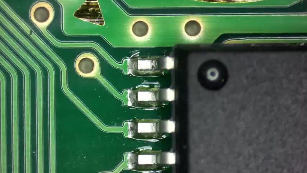
I figured out it has something to do with the EM8 chip. When pressing down on the chip it charges. I’m now researching what’s next on the wiki. But if someone has encountered this before I’d appreciate any info.
Edit: the charger if inserted at an angle charges it briefly. I’ll try to drain my battery to see if it’s just fully charged and turns off. A YouTube video: https://youtu.be/y8X3JfrDeEo?feature=shared describes the issue. I don’t have a soldering iron to try to resolder the contacts.

Only charged when I held the cable at a certain angle. I read somewhere that people think this is a noise filter for the charger.
I never had that happen to me, so this is just suppositions, but we can roll with that for now
The chip is close to the charge port
The charge port gets mechanical stress whenever you insert / remove / bend the plug
It is possible the EM8 chip got a broken solder joint due to regular stress
If you had the skill and tools, you could re-melt the joints and test out that theory, but without that you better ask for someone to do it for you - or buy an adequate iron, flux, solder, and a practice kit, to do it yourself and have some tool for future needs 🙂
2 hours of tinkering at least proved the port works sort of. So I don’t need to play god with a usb c port or replace the port at this time.
Funny enough pressing the EM8 on one corner does the trick
Do you have a multimeter ?
Yes. All contacts have continuity. However the contacts below “E” in EM8 are difficult to get a reading. So one or both contacts under the E or left side of the EM8 must be the issue. The right side is immediately responsive.
OK so the top left pad (bellow E) is going to the other side of the board to.... the charing port, 2nd pin from the right
So that kinda confirms it, as it is pin2 - VCC, which is the power pin
Still, try to get continuity from pin2 (2nd from right) to the top left pad of EM8
Don't apply any pressure with the probe so you don't artificially push the component in contact with the pad
For orientation of the needles to check on pin, are you saying test only that pin? Where should I put the needles?
one needle on the charge port pin2 (2nd from right)
one needle on the top left side of EM8
While you're here, check that it's not pin2 that is the issue :
https://imgur.com/a/qh0Jhzq
Okay, I think this is where I’m confused. Is pin 2 on top (button side) or bottom with the cartridge slot? EM8 is on the button side, the charger pins are on the other.

With the charger plugged in I’m getting 005 volts on the multimeter on the pin when tapping the EM8.
We don't need voltage readings, only continuity between the two points I mentioned
Pin 2 has continuity.
Nothing appears to be loose.
I had to step away from the project a bit. But I do know someone who can help soldering once we can narrow it down.
I'm convinced the issue is a broken solder joint
I have some doubt that you probed the right area (it you probe on the pad you won't confirm the issue)
Anyhow, a lil' touch up doesn't hurt
Let us know when you try it
You can immediately rule our EM8 with some tweezers if you really believe it is that. Keep things simple, No need to overcomplicate methods or solutions.
Keep in mind if the battery is full/charged from another unit it will not charge either.
I have to admit it has been fun to poke around and try to find the right thing. I can keep trying today.
So I should check around the charge port? I guess what I had trouble was I don’t exactly know what to look for in terms of something is wrong or not.
I did check the fuses for continuity because the wiki suggested it and they work. The only part I struggled with were as you suggested the power pins of the EM8 on one side.
I never mentioned but it’s AGS 001. But that might be apparent from the pictures.
I’ll bring my multimeter when I have my friend check it out when he helps with soldering. He probably has more experience checking continuity as an electrical engineer.
You might also want to confirm you have continuity between D1 and F2.
That's a common point of failure for charging.
Confirmed
It has continuity
From the wiki:
“If you do not see any obvious issues, you'll need to plug in the console while you have it disassembled and try and trace the power lines from the port with a multimeter. If you see power at the port and no where else, you should try to reflow the solder on the pins. To narrow down if the issue is with EM8, typically one can just apply pressure to the component (with your fingers) and plug the console in with a battery. The common mode choke sometimes will have cracked solder joints or have been physically damaged or cracked.”
I can’t replicate the second reading on the EM8. How do I trace the power lines?
Let's take a step back. Do you have continuity through EM8 filter like so?


So as HoZy mentioned, with the battery in and charger connected, use a pair of tweezers to bridge those two points. If it charges, then you'll need to replace EM8.
Tweezers charged the battery. Where can I find a new EM8?

EM8 can also be bypassed since it's non-critical filtering. #troubleshooting-archived message
What do you mean by filtering?
My friend suggested soldering “bridge jumpers” as a solution.
EM8 is a Common Mode Choke:

Yes, that is a solution
I’ll update tomorrow
So if it charges then it should be good to go? My plan was to re shell it with a new screen.
Can't hurt to clean the power switch. As for any other issues - 🤷♂️ - you'll have to determine that for yourself
Yeah. It functioned just fine. Other than not charging and having to use the battery slot on my other SP as a charging dock. But yeah. I get the while’s it’s open, might as well do a spot check for cleanliness.
I guess if I don't need tp2 then I can use the board but what is the repair process usually for burnt pads
You have to follow the trace where it leads and either find or create a new place to solder to
However
It'll be more difficult to solder to than TP2 was, and you'll have to find a way to route the wire such that the shell doesn't pinch it

Installing this mod just got a lot harder for you, and you already couldn't succeed at the lower difficulty. I suggest putting this project aside until you can get some soldering practice in
Does the burnt pad mean the button itself won't work either?
you have to measure with a multimeter to determine
or assemble it back together and try
Did this happen because my iron was too hot/I placed it on the pad too long?
many reasons but thats a likely one
Could be many reasons
to hot, to long, stabbed the pad or all together
All my solder prior were fine but for this particular one I had difficult actually sticking the solder to the pin
Kept getting stuck to the tip of the pen rather than on the board
If you want to continue this mod, your next step is to get some soldering practice kits, do them, post the results, then use online feedback from those to see what's wrong with your soldering
It's impossible to tell just at a glance from what you've done. It could also be an issue with your iron, your flux, your solder, or all of the above
Yeah I'll purchase a practice kit before even trying the routing lol
Just as an assurance
Your Gameboy is totally fixable once you get that practice in
It is far from fucked
the wanted mod still works. you could even use the required wire as a jumper if you have remove more than just the testpad
but only do this after practicing. if you succeed, remove some solder mask and take a look at the problem area
I set the multimeter to 20V to test it?
no, into diode / continuity mode. and then measure from the cpu pin to the button pad
Ok the connection from the select to the CPU is still good
Question: how does the rubber band trick work for SP screws on the bottom in the holes?

Very philosophical
I cannot see how well it is stripped, but make sure you are both using the exact correct size screwdriver, as well as not using a cheap screwdriver
Open the Gameboy such that the screen is hanging off of the desk, and use sufficient downward force on the screw
And "the exact size" isn't "the right shape", not all + shaped or Y shaped screwdrivers are the same

So I was able to secure the power switch in the correct position without fully opening it. So I simply put the all the other screws in and well, it works!

Noticed the blue channel isn't blueing as it should. Been fiddling around with reseating cables etc but that hasn't helped. I guess it's most likely I'll need to reflow pins on the CPU and FFC connectors?

yep. time to reflow the pins for the blue channel
alright thanks. shouldn't be too bad just annoying to bring all the equipment out again lol
wish I had a dedicated workbench
there is a picture somewhere of which pins are responsible for the channel. you don't need to resolder anything else
That's probably on the FFC connector side, but just in case, you can check the CPU side
https://github.com/3615Retro/GameBoy-Boards/blob/main/CGB/CGB_CPU_Pinout.png?raw=true

Thanks for that!
Spent some time this evening and fixed it. Thanks again for the hints!

Still need to 3d print the damn bracket. The printer at work was on service >_>
colors looks a bit tilted
Yo, so I have this gb dmg that has (as you can see in the pic) a dead line of pixels. I want it to be a collectors item so I want to replace it with a new original one. I already took it apart and since the screen seems to be hard to remove, should I just get a whole new "front motherboard" with the screen already attached? or is there a way to fix the dead pixels without replacing the screen.

That line of dead pixels can be repaired with a soldering iron
Yep, @stoic grove is right
Vertical lines are fixable
You'll have more trouble finding a good OEM screen than going to an electronic repair shop and asking for about 10 minutes of work, counting in taking it apart
it also has one that is sideways
its on the bottom
barely noticable
like, 3rd line from the bottom is dead
Sideways ? Horizontal ?
Turn your contrast to the max and show us
Okay well if it is horizontal it is 98% not fixable
Some have had some luck, but it's almost urban legend territory

it's possible, it's just not that easy and you need a special tool for a higher chance of success
What's the tool?
The issue is that the ribbon in charge of the horizontal lines is not made of the same kind of material as the vertical one, and will be damaged by heat.
But you need heat to restore the ribbon connection...
- this ribbon is hard to access
- manipulating the screen has a very good chance of damaging the existing connections in the ribbon
this is a wide, special soldering tip. i'll see if i can find a link
I know a guy that does ips swaps regularly so maybe he has some leftover "front boards" or whatever its called
with working screens or smth
that's why the tool

I wouldn't count myself having an OK chance of success even with the tool 🫠
I assume the ribbon responsible for horizonta lines is the one on the bottom
and vertical the one sticking to the actual motherboard
?
Horizontal : behind the screen
Vertical : under the screen
so as I said better do this than risk derstroying it completely?
Yes
hi everyone, i guess im just another guy with same classical issue : i have an original gameboy, that doesnt turn on at all. the battery contact have no corrosion, and the switch is clean. i'm trying to find some guide/video/help to know where to look with a multimeter to try to find what could be the issue.
i have two game boy pockets as well, same thing.
any help is appreciated, i will provide some pictures if that helps
Go ahead and make this a separate thread since it's a full troubleshoot instead of a quick question
The bot will comment with the details we need
Does anyone know what the "arctifacts" when the gameboy DMG loads the "Nintendo" logo are caused by? Sometimes it's dots above some letters and other times it looks lile russian language (with russian it didn't load the game).
Is there something specific that always causes this, or can it be caused by multiple reasons?
It is not supposed to load the game if the logo is garbled
What would be the cause? The DMG that had this issue stopped behaving like that after I opened it to look inside.
I'd like to know what causes this so that I can try to prevent it from happening after I assemble it
usually it's dirty contacts on the cartridge slot or cartridge, but can be some other reasons as well. bottom line, something is making a) the DMG unable to read the cart properly or b) at least the Nintendo logo data on the cart unreadable.
Is it possible to make bridges in an ags screen ribbon cable to fix a small cut? I don't know if it's heat resistant or not
pics plz
F, listing disappeared. It was a 101 screen with a small cut in the ribbon that caused 1/4 of the screen to not show anything
I know some ribbons can withstand heat, like the ones used for the screen mods. But I don't know if the ribbon of ags screens can also withstand heat.
I don't have any broken screen to try 😆
most likely not worth it, to mod a GBASP you just need a working board, the rest can be sourced
ITA and M2 are good, 101 lookalike replacements
I finally got a gbxcart. I backed up the save file and ran it on an emulator. It still has the same glitch at the same spot. What would that mean? Corrupted save file?
Did you extract the ROM file to use on the emulator, or did you obtain it from somewhere ?
Send your save file here please 🙂
Is Final Fantasy V Advance a commonly bootlegged game? Pricecharting says loose copies are around $30, and there are plenty of ones on eBay priced that high, but I also see a lot that are around $12, and I can't tell if they're fakes or not.
Those are fakes
All the FF games for GBA are common bootlegs
Less so tactics but yeah
Sadge, I'll have to be careful when I go shopping for a real one
Good sellers online will show you the board and sticker imprint
Yeah, true
Also I just realized there's a dedicated thread for asking about game verification, sorry for not posting there
Uh. I am a bit software illiterate. I backed up the save file with gbxcart. then loaded it with visualboyadvance. I just did a backup ROM and it came back with an invalid checksum
@cosmic swan Exactly what I wanted to check 🙂
Your ROM could be corrupted, in which case there is nothing we can do
Clean up your cart pins outside of the shell with IPA, just in case
Send me your save file so I can try to load it on another ROM
#1006398521576005663 message
This is what I get with your save file (up the ladder) on a clean ROM dump

That means your cartridge is probably safe, but your save file might have an issue..
77 hours in the file, that's a bad situation
I don't know enough about save files to be of some help...
Could throw it at pkhex, maybe it can recover
I tried it on my cartridge, same situation
Right but pkhex is a save modification tool for pokemon so it may give some indication what's still good
And if like location pointers are messed up maybe it can fix them
What I find weird is the fact that his ROM dump was invalid
I'm gonna try a trickeroo
sending you the save file in the meantime
I tried changing a few things and re-saving with my known good ROM, just to see if something could be corrected
The glitch is still there but it's not the same pattern now
Escape rope got me to pallet town
I'm guessing something in the map data saved got corrupted but getting out of that map fixed it
Also this save very clearly had game shark codes used or the missingno glitch used cause there's items that don't make sense otherwise
Ah yeah. Just missingno. No game shark on it.
Ive done a few more test back ups and the check sum came back fine every time now.
Pokémon is weird in that some of the map data is in the save so like if that got messed up it can try to send you to a map that's unexpected/doesn't exist
OK cool so your cart seem overall safe 🙂


TIL, thanks @remote hound 🤍
https://m.youtube.com/watch?v=z5CRnx9QAY4&pp=ygUNR2VuIG9uZSBsdWdpYQ%3D%3D not entirely on topic but kinda explains what I'm talking about

Recently I tried shiny hunting my favorite legendary Pokémon in Generation I using arbitrary code execution. Here's how it went!
-- Resources!
TimoVM's Gen 1 ACE Setup: https://glitchcity.wiki/wiki/Guides:TimoVM's_gen_1_ACE_setups
Nickname Writer Codes: https://glitchcity.wiki/wiki/Guides:Nickname_Writer_Codes
pret: https://github.com/pret
Po...
OG Gameboy that won't power on anymore. Any ideas where to start to fix my console? I'm looking for a repair manual or anything that will help me troubleshoot.
Post pictures of the board
Yer gonna hafta open it up regardless of whatever fix you find
Yeah, I know, I'll have to when I get home. Post here you think or make a new thread?
Prolly better to make a new thread
@mighty raven #modding message
Do you own a multimeter ?
I don’t no
Oh shit
I see why the L button isn’t working lmao
Your picture seem to show quite dirty triggers
It’s covered in rust
Like coveredddd

Besides both these triggers the board looks amazing
Not dirty at all
But both of these triggers are covered in that
The left one also sounds hollow. While the right one actually sounds like I’m pressing something
You could try to clean the trigger switch
I have another board with 2 working triggers. Is swapping them harder than just cleaning it?
Start with cleaning everything you see right now and try it again
If that doesn't help you can open the trigger switch, I'll give you instructions
There’s rust going inside the button as well

Alright will do
Sure you could swap it
It's not as easy to remove as other components so it depends on your experience
I have close to no experience haha
So I think I’ll try and just clean it out first
That would be better
Alright gonna give that a try then will report back
Already looks so much better after brushing with ipa
@coral scaffold Issue resolved! Do you think the problem will come back or am I good?
Toothbrush with ipa, then q tip for the areas that didn’t come off
I’ll send a pic when I get home
@coral scaffold


The left one still does sound different though
But the button itself works
I was testing my FP GBA ITA screen, and when I turn the power switch on, the speaker makes some staticy sounds and there's no image on the screen. My first guess is that the power switch needs to be cleaned, but I wanted a second opinion
Wait nvm the batteries I were using were just dead lol
@calm shore Is your gameboy 20+ years old ?
(yes)
So the power switch needs to be cleaned anyway 🙂
I didn't get this ping for some reason oof
But yeah I know, I just want to save that for when I know how to solder
Though admittedly I am afraid of opening this thing up again haha
quick question, is it common for GBA SPs to experience low volume á la GBC? I got one of those from a coworker to fix and it seems the cap is gone (speaker is new, volume pot was somewhat cleaned with IPA)
Yeah it’s not uncommon—I’m assuming you cleaned the power switch already?
not yet, didn't have time to do more than a quick disassembly and inspection
Hello! I was cleaning some corrosion off of my GBC and the paint on the motherboard started stripping off. Is this something I should be concerned about?

Hi @rough cliff
This is what the area looks like underneath
You should clean the surrounding with vinegar, and rinse it
Then if you can, add a UV coating to the copper to prevent oxidation (some nail polish do the trick in a pinch)
You've got oxidation in some via (the small holes) but that's all going to ground so you should be all right even if the via is dead

the copper will change color. you can also sand it down and repaint it. nail polish is an option if you don't have uv curing soldermask
Yes to the vinegar, check that cap in the corner as it may have been affected
Thanks for the help! I'll have to buy some solder mask, but I cleaned the area with vinegar and ipa
Hey everyone, I've got an issue that is more irritating than anything...
I've got a DMG Gameboy that's modded with a RIPS v4 (q5) screen kit from Hispeedido. The kit allows you to set completely custom palettes, and the kit saves these settings typically. The frustration I'm facing is that sometimes there seems to be a glitch which causes all the palette settings to be lost. It takes quite a while to set these again when this happens, since the only way to fix it is to do a factory reset then manually go through a clunky menu to get everything back to how I like it.
Does anyone know what could be causing this to intermittently happen? I initially thought it was the regulator failing, but that has been replaced by a Bucket Mouse DMGC regulator I built now, and the problem has persisted. Am I doing something else that could cause this? My understanding is limited on this.
Thank you so much for any help!
@grand flower https://discord.com/channels/246604458744610816/1354218573374947519
Pretty sure you ripped another pad before closing the topic
100% did
Actually ripped most of them while trying to use wick and clean. I think the temperature had a lot to do with that? Since I was using 330 which might be too high now that I'm looking into it. Apparently 60/40 is better at 280? (Was doing 330 last time, did 320 this time)
Good news through my second attempt went better


It ain't pretty but it does work

Not aligned exactly perfect but it does work
I used a lower temperature and took my time this time.
Before this cart arrived i practice a lot more in just removing stuff and putting it back on. Not sure how i can get more steady hands. 100% does feel like i need a microscope of some kind instead of using my eyes. 
I got two jp rom chips available idk what to do with them.
Last image, I can't complain long as it works. If anyone can clear me on this I'll consider it a finish job

If you iron is a bit weak, you can cut off a piece of solder wick braid instead of using it from the roll
I may try that while working on my second crystal. Some reason feels like my tip isn't holding heat the same anymore? It's the reason I set it 320c now when I originally did most my gbc stuff at 280c no issues. Maybe I just need to replace the tip.
Feels like i shouldn't end up with an more rip pads on the future
Ran my rework station at 320 with no issues since I had held it back quite a bit
Don't drag the wick around, if you are doing that.
Generally, the wick lifts pads when it cools down enough to 'stick' to the solder that's on the pads.
That would explain a lot, glad I didn't really do too much of that this time. Only used it when two legs bridge this time 😅
99% sure that's the cause, I just automatically assume it always was a temp issue
Temperature is one of the factors. I'm not experienced enough with temp. control to say anything about that tough, so I'll refrain from commenting on that (I use one of those generic irons where you can't adjust temp.)
Although, a wider tip should help too (i.e. better heat transfer), as well as flux.
@clear plank glad to see you solved your last gbaHD issue
Did you ended up replacing or servicing the switch ? 🙂
Ordered two from handheld legends.
Are the aftermarket Cart slots good?
I never ordered any
I know funnyplaying made a plating (I think ?) oopsie at first but then updated them to be good
Ok good. I just glad to be done with the project. I have too many. PixelFX 3DO gem, I have two X68000s to repair a Vectrex to recap to name a few
Hope you have some good stackable project box 😄
Gonna have to let us know 
I have 26 boxes full of retro consoles
Most of them are modded. I took a two year break(divorce etc).
I had an interesting experience today with fixing a Pokemon gba game and was wondering if anybody knew why the game acted the way it did.
I took a copy of Pokémon Emerald that had damaged pins and swapped the rom chip onto a Japanese Ruby board. Upon startup the game played, only giving me the option to create a new game. I then tried to save the game and it gave me this screen:
https://preview.redd.it/have-you-ever-encountered-this-rare-screen-v0-xsj8wf0a2cle1.png?width=758&format=png&auto=webp&s=9d991a2c4a6516ae04c167ff94596c19426995f8
eventually it said the backup memory has failed and told me to turn the power off. I retried turning it on, and it gave me grey screens after the gameboy intro, and then i couldn’t open it in the DS screen (showed that there was a gamepak connected but did not give me the option to select it).
Eventually I got it to get through the emerald intro where it then gave me a screen that said “the file has been erased due to corruption or damage”.
The next time I tried to save, the game froze, and then after some more resets and grey screens, i got it to play and then it just randomly saved. After that, it’s worked like normal. Does anybody know why exactly the game had so many changes in behavior? I assume it’s because it was a Japanese ruby save file that was still on it, but the behavior was really odd and interesting. That’s all, thanks!


Hello again. I’ve been testing my stock DMG and my GBC, which is stock aside from a busted TFT screen, and I’ve noticed something potentially weird? On the GBC, in top down games with four way movement, occasionally while holding a direction on the D-pad, it will stop registering. Usually I just apply slightly more pressure and it registers again, but it’s kinda annoying. On the DMG I don’t have this issue. I guess I would describe it as the DMG feeling more on/off with a D-pad input, whereas the GBC I can press like 95% of the way and it sometimes won’t register. So far I’ve tried cleaning the membrane, swapping the D-pad to an aftermarket one, and using the stock D-pad with an aftermarket membrane, which seems to have helped a bit but the problem persists. I’m wondering if it’s normal for it to work like this and I’m just nitpicking?
Did you drag the membrane on a piece of paper to refresh the contacts ?
I hadn’t tried that, no. For the original membrane, I tried IPA but the q tip started turning black and I thought it might be damaging it so I stopped. I’ll try the paper with the original and the aftermarket membrane.
It's ok to have some black marks left by the membranes
Just a few strokes, flat on paper is enough
Hmm still seems like it’s behaving strange. Same thing with aftermarket membrane working slightly better than OEM. On the one hand it could all be in my head. On the other, I did see a video saying there could be like tiny fractures in the board that could cause this issue. Would be nice to have another GBC to compare against but I probably don’t need to be spending on more handhelds lol.
You can continuity test your board with a multimeter and have another set of hands gently push to see if the connection breaks up
I never had that happen to me, but it is plausible
my gba sp screen has a little problem that's really bugging me.
Look up-right from where the character is, and you'll notice a little vertical line, that blurs the image a bit.
Can you tell from this video if its a problem with the lens, or if i gotta replace the entire screen? Thanks
(zoom in this picture too, i dont think i can capture it better but its more noticeable irl)

i think discord's compression just made it unnoticeable in the video😅
in the lens, in the screen, or both?
I have a weird issue, yesterday I accidentally slept with the gba
there is a chance I slept on top of it with my face (lmao)
it turned on so i gnored it
then I tried to turned it on today and found some liquid, I thought it was the GBA USB-C i got, but that was completely dry
the liquid was only around my Ezflash Omega DE
and around the cartridge holder
GBA wont turn on now even after I cleaned all around it
what could it be ?
light flashes green for a sec and then its gone
(my gba had history of needed the switch cleaned once) but the liquid just throws me off o what the issue is
ayo, sus 
I tested the cart on other systems it worked, I cleaned it with IPA
There was a smell of like feet idk how to describe it 😂
Mechanic oily
But not terrible smell
Is it anywhere around the battery, by any chance?
It was on the exflash cart only
I checked the whole battery area and nothing
No smell not leak
That liquid was only on the back on ex flash
And on the cartridge reader of gba
The back plate
The gba is also IPS modded but I saw nothing when I picked it up
I'm guessing you're able to disassemble the console, since you mentioned that you cleaned the power switch in the past?
Do you have a multimeter?
Check if there's continuity on F1
I'm wondering if maybe you might have drooled on it, seeing that your were face down 😅
There is a chance
I’m a a drooler
Where do I put the pins for the continuity ? Completely forgot

You'll have to open it up. The fuses will be on the board.
For the multimeter, put it into that diode symbol below (above the CE logo).
Touching the leads together will make a beep sound if it's in continuity mode.
If not, just press that orange button on the top to select the next mode (since there's two modes there)
Oke opening up
F1 is over here (circled in red)

See if you get continuity there.
Carefully place the leads on either side of that fuse
also, have you cleaned the board yet, since you found that liquid?
with IPA?
Only around the cart
Okay so I opened it I’m looking at F1
So I place both on different sides of F1 ?
Ok I saw how to put it
Yes it beeped

If it helps with any obvious issue that I don’t see
The fuse is good then. Could you post a pic of the board?
It's likely shorting out somewhere since it immediately shuts off.
oh nvm
Ye that’s the feeling I get
It reads then off instantly
Took a cotton swab and cleaned around a bit with IPA not that it was really dirty
Mmm still the same even with normal batteries
This is the other side

Good and bad news
I cleaned this a bit with IPA

Now the power remains
But no picture
Did my drool 180 no scope headshot this thing ?
Yeah that ribbon is toast, you can probably find a replacement for a few bucks tho.
Just make sure it's for the right display and that it's for a GBA with the 40 pin ribbon connector.
Any idea what did this ?
sounds like drool did it lol
Damn, only 2 times I have slept with a device one I elbowed a laptop and now this 💀
Does replacing the cable require soldering ?
I just got an iron but I have no idea how to use it
At least the carts are safe ah well
No soldering required! Just unclipping the fasteners that hold the ribbon in place.
Also, please buy a soldering practice kit or two before attempting to solder anything on your game boy.
Could you tell me exactly the na Eid what I’m looking for ?
Yeah that’s why I wanted to hold off it that was the solution
At least I have a ds lite and analogue pocket I cans still play for now
eh? Not sure what you mean, ribbon cable depends on the type of display you have.
Ye I think it’s funny playing v3
Is yours attached to the board, like this: https://funnyplaying.com/products/replacement-ribbon-cable-for-gba-3-0-ips

FunnyPlaying
REPLACEMENT RIBBON CABLE FOR GBA 3.0 IPS IPS ribbon × 1 The location of the chip is different, everything else is the same.
I hope not lol, that's $40
Yes like this
Dam 40$ might as well buy a new kit 
Sadly the ribbon cables are the most expensive part of the kits
Doesn’t look terrible. Could clean that up with some IPA and a toothbrush.
Probably dirt. It's a 21 year old game. 
Definitely no water damage--if it runs and boots fine now chances are it will continue to do so longer than you'll be interested in playing it. That scuff mark might be worn off solder mask. If the trace was broken it probably wouldn't boot.
Is that an impact or just some dust ?

Yeah that’s what we were chatting about—I think it’s a scuff but if it boots it’s probably fine?
They can get worn even not being opened, also that picture is opened lol
shivers
Just the edge connector is fine unless you spot something egregious.
Yup, that’s probably just leftover marking from the manufacturer tho
If it doesn’t come off with a q-tip and ipa leave it
No sense in scrubbing or anything like that
Custom ROM Doesn’t save!
Hi guys, I recently bought a flasher and some re-writable cartridges off of Aliexpress. I’m trying to write Megaman Battle Network 4 Blue moon with a patch and my save to one of the carts. However, once written, I am unable to save on original hardware. I’ve tried changing the save type, trying to make it a battery less save using tools, SRAM Patcher, HexEdit, nothing works! It saves in Emulation but not in hardware. Is there any way someone can help me with this? Thank you so much.


A lot of bootlegs use patched ROMs that actually overwrite part of the flash memory when they save instead of having a separate chip for saves. That might be the case here.
Oh wow.. I see.. how can I do that then?
If that's the case, you're kind of out of luck. You'd need to reverse engineer the ROM, come up with your own patch, and then see if it works. You'd be better off getting different cartridges with a separate chip for saves or a proper flash cart.
But I have no idea if that's actually the case here. Mostly just putting it out there to be aware in case that's what's going on.
Does anyone recognise this fault? Is it capacitor or cpu related?
Boards are clean and screen connector is also clean. The video is with a game cartridge inserted
CPU or RAM are at fault here
Oh, F.
Any way to know which one besides swapping the chip? Voltage readings, oscilloscope, heat signature, etc
Oh no, it's a blob board 💀
My cart froze and started beeping, did some cleaning fully on it with IPA , feels fine for now. Is there anything else to do on that situation ?
Happen with all cartridges if it's dirty enough or if you bump it hard enough
Clean it and see if it happens again
Got a pokemon yellow cart, game crashes almost instantly. Just saw this on the board. Any recommendations for how to repair?


There's a lot of small issues here and there
I would start by removing the battery and doing a good clean of the PCB, so we can see what we're working with
Do that and then show us a picture of the front and back
In the meantime, this is what concerns me

Thanks for taking a look and giving me some ideas, I'll give that a try!
Is this pin still there?

yeah, I reflowed it after this too
But the pin looks either bent or missing


Thiz dont look great tho xD

Got a cool message last time I tried the save

I was not able to detect continuity from here, not sure if its supposed to but it looks like it should eh?

probably but also you should be using flux cause if you are re-flowing joints and they go cold they won't have as good connectivity.
Wow, I thought that pin had something wrong with it but it was just weird lighting.
Check the areas highlighted by White whenever you can
there should be a trace going to each via
test on the other side

Actually these only go to TP2 and TP3, the test pads, so it should not be an issue
Removed battery and cleaned up the board. Game still crashes soon after booting up


Have you checked for loose pins?
hey yall, I installed a Funnyplaying M2 kit into my AGS-001. I'm noticing that on some occasions, the brightness/screen settings will start activating from random touches on the back of my screen.
first question: where are the touch sensors on the M2 screen? and secondly, could i have installed it improperly?
I have a copy of Link’s Awakening that had a loose pin and this issue. Cc @south pike
if you google the same question you will find a post with pictures and how to remove it
yeah, a couple times and reflowed the board a couple times too with plenty of flux and iso
I'll take another closer look at the pins, thanks!
The back side's photo is quite blurry, could you re-take it ?
@glad locust About your button pads, if you already cleaned the pads and the golden contacts, you can try to rub the black parts on a piece of white paper
Drag it once or twice, it should leave a black trail on the paper - Don't over do it, one or two strokes should be enough
I'll look at it more thoroughly tomorrow :)
Got a broken GBC today, I expected an easy fix but got a short in C32 + pad instead
What I don't understand is nothing warms up when injecting voltage
I lifted the cap and the short is gone, but I have high pitch noise.
Can a missing C32 cap cause the noise? I don't have another cap to replace and test right now
I've got a fucked up DMG board that I've gotten clean enough boot up a game. I get the Gameboy logo and then the screen blanks out. I know the cart reader is pretty messed up but would there be any other reason for this to happen?
Update: Tried a different game and I get the "screen off" line at the top that doesn't go away until I turn the unit off. Might be trying to push through so much corrosion that the regulator can't keep up?
I have one that might have the same issue. Game Boy logo drops, and as soon as the game loads, screen goes blank and power consumption drops to 27~33mA
I haven't had the chance to look at it yet
I would refresh the solder on your cartridge slot pins
After that, you can try to trace your cartridge slot pins back to the CPU and see if any has an issue
Does anyone know what would cause an issue like this on an IPS screen? The lines are discolored but each boot they’re not the same lines or same colors.


I think the screen is likely faulty, but just wanting to see if there was any solutions before I buy a new screen
Make sure the ribbon cable is seated properly. If it is, that display is borked.
Hi guys, got a hopefully simple question I hope isn't too dumb and is in the right place.
I was looking at some assembly to enable a HBLANK interrupt https://github.com/gbdev/gbdev.github.io/blob/3b9a4d7f200c625dd5a04951708b1870a0e773b8/website/.vuepress/public/deadcscroll/DeadCScroll.asm#L1452
This, if I'm understanding correctly, follows the sequence:
- Specify which interrupts should be enabled.
- Enable interrupts.
- Clear any interrupts which were queued but never handled.
Is this the correct way to do it? I would expect that you would want to have the pending interrupts cleared before enabling them. But I expect there's a reason for this sequence I've not managed to find (or understand if I have) by searching.
This would be better in #development honestly
Oh, they left 🤣
Ummm ok, so I bought an EZ-Flash Jr and the saves seem to work, but the RTC resets every time I turn it off and turn it on. From what ppl are saying online, the RTC and the SRAM are powered by the same battery, so if one is working and the other isn't, it's a firmware issue? I haven't run the firmware update file though, because the EZ-Flash website seems to imply that is perhaps a bad idea and the cart already says it's on FW4 (K1.04e)
Just not sure how to proceed. Maybe should crack it open and see what kind of a battery it needs, as it looks removable and not soldered in. But also the documentation on this seems to be largely community driven and somewhat inconsistent.
It's likely that your battery is almost dead. The RTC probably needs a higher voltage from the battery to keep time Vs the voltage needed for the SRAM
Can you measure the voltage and report back ?
To add to this, if you finish your game sessions by pressing the reset button (allowing the menu to save the sram to the SD card) then even if the battery is completely dead the SRAM will hold the save for this as it is being powered by the Gameboy itself. This is something we recommend if people want to use the cart with a dead battery.
@eager fossil will ping you as it has been a few hours. Let me know if you measure the battery
A whopping 280mV!
This battery is dead af lol
holy shit
I can't even believe it managed a save on reboot
likely a capacitor kept power to the sram during a brief power off/on if that's what you mean
Yeah get a new battery in there and enjoy it!
Aha! Thank you, excited!!
Hi! I got two authentic Japanese Fire Red and Leaf Green today from eBay. They did not work immediately so I cleaned the pins with 91% isopropyl alcohol. And they work now but the catch is they don’t read fully inserted. Just slightly pulled a little back out. I’m assuming it means the pins need another cleaning? Maybe toward the bottom of the pins. Or I guess I’m asking if there might be another issue.
My gb operator, notta gameboy handheld, and my gba sp all work with the cartridges partially/mostly inserted. The gb operator says they both are authentic once it reads them inserted as I described, and I can show the interior of the cartridge boards too.
I think it’s SOLVED for now after 3rd Qtip/Alcohol cleaning.
Share some photos of the circuits so we can inspect that 🙂

The picture is after a third cleaning. They boot immediately in my Gameboy now.
All good then 👌
Yes 💯
No sound. Stumped I cleaned everything with alcohol re soldered all the pins not sure what’s wrong.

Tried 2 different speakers and one off a working gba nothing
Volume wheel works with headphoness; can’t get speaker to work.
Did you already clean the headphone jack and make sure it isn't making a false connection?
If it thinks there's headphones, the speakers won't play
looks crusty

I agree with march here, probably a dirty jack
Watch the top part making or breaking contact
Some oxidation or dirt could be preventing it from connecting
You can clean it a bit and try to make contact with a piece of metal, see if it works
Everything was good then out of no where screen started to flicker between pallets. I read online I can just take off the chip for the sensors.


Tried to clean off solder points, putting something to stop contact and removed the sensor pads pallet stopped but pixel flickers
That's a different issue - did you fix audio ?
Yeah audios good
Noticed it’s specifically flicking on the pixels pallet
Gonna re solder the touch pads and try relocating them.
I think I broke one though
read on Reddit that I just gotta get to the “touch” of the os menu to turn off the touch pads something’s making them contact I feel like. Could be the thickness of the mod