#Troubleshooting
1 messages · Page 5 of 1
Alright, that tracks
So which probe goes on the component I'm checking, and where does the other probe go? Ground?
You're in luck! Froggo made an excellent video about checking the fuse

Troubleshooting a Game Boy Pocket with no power! All troubleshooting experiences are different, but this will walk through some potential problems and strategies for addressing them.
Etsy shop: https://froggocustoms.etsy.com
Instagram: https://www.instagram.com/froggocustoms/
OSH Park projects: https://oshpark.com/profiles/leggomyfroggo
Thank you
Does this video go over other possible power problems? Because I just tested continuity with the fuse just like the video showed, and the multimeter beeped, which means the fuse should still be good
Could you check the dcdc board and see if it outputs 5v on pin 6
How do I check that with the meter?

Okay, so two things
Putting red on 6 and black on 3, it beeps for a split second before stopping
you need to change the settings on your meter. you want to measure dc voltage, not continuity
Oh
this setting


experienced chopstick eater :D
はい
knew it
Oh shoot, my mistake
nono i forgot to say
Classic heheheh
Do you have a battery tray / pack you can hook to the MGB battery contacts?
Well, I turned the Switch to the on position and those points are still outputting nothing

When I do that, it mostly shows 4V but sometimes dips down to 3
Well I didn't have any batteries in when I was probing it, but when the system was assembled I was using AAs, not AAAs
But uh
I just tried putting batteries in and it suddenly turns on again???
well thats good :)
Well while I have it disassembled I'm going to try fixing the screen alignment
I cleared away some fuzz from around the switch earlier, maybe whatever that was was causing a short
you probably have a dirty power switch that really needs cleaning

Looks like the switch shield hasn’t been desoldered so I’m leaning towards a dirty power switch like zip mentioned
If issues persist I can try cleaning the switch, but idk if I have the skills available to do it myself, especially with that wire already installed.
Do you think anyone might help if I put up a WTB listing in #1049401311101206649?
Ok we cleaned the switch ourselves, but it didn't appear to resolve our issues. Putting the OEM screen and back shell on didn't fix it either
What should we try next?
Was I supposed to have batteries in when I was troubleshooting with Kirk earlier?
Also is there a way to check if the switch was cleaned well enough?
For now I've put everything related to this MGB safely in a box until we can find a way to power the system without having the back shell on
I just remembered something important. When I was watching Froggo's video earlier, there was a part at 10:35 where he checked for a short between VCC and Ground underneath where the DC/DC board was. For him, the multimeter didn't beep, but when I did it, it did beep.
Unless I wasn't supposed to be on continuity mode for that, I think this could be related to the problem, although if so it's weird it didn't blow the fuse
We also weren't soldering anything in that area of the board, so if something did happen there that would be really weird
I've had problems where while desoldering a power switch, solder splattered on the CPU in one of my Gameboys, not sure if it's what happened to you, but it's definitely possible
not that the problem is the CPU for you, just the fact that solder can splatter
I doubt it, we looked at the area around the switch with a magnifying glass and our solder work appeared to be clean
I made my own thread on the issue: #1166820626430963844
Does it melt solder?
and yes, with ease
you think this screen is just dead?
Seems like the RTC in my Midnight Trace flash cart resets when I take it out of the cartridge slot
Or I think it resets after sometime with it off.
U think it's just a dead battery, or some issue with the rom, or how it was flashed?
do you have a multimeter to measure the voltage of the battery? start there
I was having a similar issue—reflowing the rtc and area around it fixed it. There’s been sketchy soldering jobs coming out of FP lately.
But like Zipplet said, start with the battery.
Anyone has any experience in using electronics cleaner (spray like wd-40) in cleaning cartridge or gba boards. Isit effective and are there any “not to dos’”
I've used contact cleaner in the past. Don't do it - the oils that it contains can ruin the plastic
Thx for the headsup
you're welcome. Instead of that do this:
- remove the PCB from the plastic shell completely (very important) to avoid IPA getting on the plastic
- use IPA and cotton swabs to scrub the contact
- if it's still dirty use a white pencil eraser and follow it up with IPA
Roger that!
ok I've exhausted my search options and sent in a request for warranty on this thing but figured it's worth asking in here: has anyone had an EZ-Flash Jr randomly just "stop working" entirely? like complete failure, board is showing a short between VCC (Pin 1) and GND (Pin 32)
is the short still there if you remove the SD card?
yes
one of my thoughts is some sort of mechanical failure inside the slot either way
since it's in warranty there's not much I can suggest unless they tell you to keep it and offer a refund/replacement. if that happens I have some ideas
yeah if I have any issue with getting a replacement under warranty I was gonna the ol' reflow the whole board thing next
I dont have mine apart right now but there is probably a 3.3V regulator on there
and I would check if that has gone short
one more thing. check the board carefully with a magnifying glass - there's a small chance that a spec of solder got inside and has moved to bridge pins if you were using that cart around your workbench
it's been in a drawer, but yes, I already did this too
Hi all! I'm working on a Natalie the Nerd style PoCo and I can't get it to boot. I've verified everything is soldered in the right spots, but I can't figure out where the disconnect is between power and the board. I installed a USB C and confirmed it is properly sending power to the Safer Charge board(led lights up), but it doesn't seem to make it from the Battery or the Safer Charge to the actual board itself. Where do I begin to diagnose this?
This is going to be a big one - please open up a troubleshooting thread and include lots of pictures of your installation
^This^ but also I have a funny suspicion you used a CPU-06 board.
I will absolutely do so when I open the project back up again this week.
I made sure to use a CPU-05 board!
Ah, good 
I'm fairly certain I soldered everything properly to all the vias. My sneaking suspiscion is that something is up with the power switch when I desoldered it from it's original location to move it over to the MGB location. But I'm not certain how easy it is to ruin a power switch. Seems like a pretty straightforward "complete the circuit" type of mechanism
Did you beep the vias yet? You can check the power switch with a multimeter, too.
check if the lid of the switch is properly seated

Noticed some (maybe stress?) whitening on the post next to the dpad - would this a problem or nah
Doesn’t go around the whole circumference of the post
No, just be gentle re-screwing the screw to that post
Alright my gamebit arrived and I'm back with my crystal opened up


Game does not save, battery does have voltage
Could just need cleaned on the back further
But idk what to do to safely clean it
Gonna be in bed soon but I'll check back here when I'm up to see what y'all have to say for how to potentially fix the game
Clean the board with 99% isopropyl alcohol. Those solder joints on the battery look pretty poor, I suggest reflowing them with some flux.
Childhood '32 in 1' bootleg no longer booting. Gave it a good isopropyl scrub and a new battery. There is some pin scratching I can see. Anything else I can try? Even more pin cleaning maybe?

Are those HASL pins?
Don't know what that means.
Are the pins silver?
Definitely not as gold as a legit cart
Looks brassy now, but that might just be the lighting reflecting. Might be silver in proper daylight.
try cleaning the pins with a white pencil eraser and following up with IPA on a cotton bud/qtip
send us a pic of the back of the board
Will do. Hold on, good camera is old and need to physically insert and remove storage drive.
Not much going on in the back

A question about the ez flash jr
When I first booted it up after putting a new micro SD, it told me that battery was dry, but after updating I don't seem to get that message again
should I change it?
Yeah it's defo dead
just put the hour, resetted then boom, gone
nvm lmao
Hard to tell with the light oversaturation, but these look sus.


Like 99% of the Jr's arrive with dry battery.
My multimeter probes too chunky to test some of these, lemme get back to you. The light saturation doesnt help - in person these look more exposed than broken.
I leave home and get back home in the dark, so its always a struggle to get good pics.
Exposed isn't optimal, but wouldn't cause non-function. Assuming it's not a blob failure, the next expected culprit would be either a circuit break or short.
lemme mod my probes and test all these traces better.
Hey Everyone! Just got a Joey Jr in the mail and I find that alot of my cartidges dont work

Ive got the same issue for both gba and gbc
Most people here (myself included) have GBxCarts so I don't know much about troubleshooting the Joey. Can always take the basic steps:
- is the firmware updated from the source
- are your games clean
- are your games real
I hate my Joey jr
Have you cleaned your carts, even if they work on the gameboy clean them anyways
Yeah I have a little credit card game cleaning thing
The color just went away while playing Pokémon Silver. The game itself is working otherwise. Initial skim of Google isn’t showing anything. Has someone run into this before?
did the game reboot when this happened?
it's possible to glitch pokemon GSC and make the game reboot into black and white mode. graphics will have glitches as well. just power cycle to fix it
No, and on further inspection, when I turn on the Gameboy the bolt screen also lacks color
Boot*
which IPS kit did you install? you probably swapped palettes
It’s an LCD from Retro Game Repair Shop
There are like 5, which one specifically?

Retro Game Repair Shop LLC
Please be careful when connecting the flat cable. If the flat cable is inserted reversely, it will burn out the console's fuse! See images for information. Product features: 1. 2.45 inch TN LCD. Original size. Easy installation. 2. Supports point-to-point display. High brightness display. Long press the touch sensor fo
Was finding it
Yeah, so you just need to long press the touch pad until it swaps back to the regular palette

Without having it in your hands, there is no way to troubleshoot whether it works or not.
And, at a glance, there is nothing to clearly say whether it does or does not from these images.
yo! Just got a dmg with no sound
what could be the main reasons for that to be like that?
As in, what kind of general issues happen with dmgs to leave them muted
Check if you have audio from headphones. If yes, switch in headphone jack is probably not closing. If not will need to do a few more checks. The gameboy wiki for the server covers quite a bit of these type of issues.
Description: Common issues with consoles and game cartridges...
https://gbwiki.org/other/commonissues
Probably oxidation on the contact isn't allowing it to close, so it thinks it's always in headphones mode. That would prevent speaker audio
would you suggest a new jack, or cleaning the old one?
I would attempt cleaning first. New/replacement jacks for DMG are hard to find if you don't have a donor
Roger that
If cleaning it doesn’t work: https://retrogamerepairshop.com/collections/dmg-audio/products/game-boy-dmg-headphone-jack-interface-oem-new-replacement?variant=39816414593196

Retro Game Repair Shop LLC
New old stock Game Boy DMG headphone jack on PCB. This is an original Nintendo part that is in new, unused condition.
Or you can build one of those new ones that use an aftermarket jack

GitHub
A Recreation of the Original Game Boy, With a Few Modern Twists - kamicane/Super-DMG-01
the super DMG jack is a great example, the parts are all available on LCSC and it can be used with a stock DMG board

I was just watching Tito's video about it
Looks sick
I wonder, is it possible with a super game boy 2 cpu too?
yes it will work with a dmg cpu or any super game boy cpu but lets move to #modding if we want to discuss further 🙂
that's cool beans
hey,
got two GB pocket, that dont turn on, any advises on where to look first ? checked the switch, seems clean to me
Did you check the fuses?
which fuse ? and how 😄 ?
im about to clean out the switches as per a video shared on #gameboy first (https://www.youtube.com/watch?v=Q7U-Ix3TBks)

I regularly upload and share tips and knowledge on Instagram: https://www.instagram.com/natalie.thenerd/
Join my community, Modded Gameboy Club: https://moddedgameboy.club/
I'm not responsible if you make a mistake! Pls recognise your own skill level.
Use code "NatalieTheNerd" at Retro Game Repair Shop or Retro Modding to save a lil cash and ...
you need to own a multimeter
and yeah if the one of the fuses are blown no cleaning will fix that sadly

i have one, but wasnt sure what to test
after watching your video Jack, the "fuse" seems to be the resistor in bottom right (when screen is facing down)
it beeps for me....
create a troubleshooting thread and post clear pictures of the front and back of the board
So
As some of you might have seen in #gameboy
my SGB2 is for some odd reason piss-colored
lets get the obvious question out of the way first - do other super nintendo games look normal?
im not aware of anything that would cause the screen of only the super gameboy including the borders to get a horrid tint, so please check that first
Yeah, they do
I’ll check in a bit but they do
Huh
No they don't
they look pissed too
the hell
yeah I'm flatout stupid
Scart had moved a little
Might as well ask
When I boot up a game with super gb enhacements via Ez Flash
Do the enhancements apply?
Nvm, forget that
Is there a reason on why my ez flash jr's sd won't be recognized by my computer?
Does it show up in Disk Management?
accidentally pulled up the positive soldering pad slightly when removing the capacitor, it still looks connected to the board but could this cause issues when I put another one in its place?

how did you remove the capacitor? you need to pull quite hard to damage the board like that
looks like you lifted the other pad slightly as well

if you flatten everything out carefully you should be able to attach another one without issue
I did it by applying heat to both sides with a solder and gradually wiggling it out but at the end i mustve not fully detached the other side from the solder pad so when i pulled it took everything with it
Thanks for the confirmation!
one thing to keep in mind, once the new cap is installed if it wiggles around you will need to secure it mechanically
just out of curiosity, what will happen if its left unsecured?
If it's ever dropped or jostled around, the capacitor can break free and take some of the pad/trace with it.

Are these white LEDs around the corners
Normal?
I bought it ages ago and only now popped it into a build
Er, what are you referring to?
I'm guessing theyre refering to this:

My SP isnt charging after fixing my C58. Fuses show continuity. EM8 shows continuity if I measure across the left legs - not sure where it's supposed to be measured? Showing no continuity from D1 to F2.
Not sure if related - didnt attempt to charge right after fixing C58 - I let the battery run out and found out it couldnt charge this morning. Just thought I might mention it.
Try jumping D1 to F2, that should fix it.
As in solder a wire between the two?
Yes, or you can dig deeper and try to repair the trace but it usually breaks under the cart slot
How the fuck did that happen lol. Cant imagine ive been anywhere close to that area while fixing C58.
You had continuity before?
It charged before 🤷
That is odd
Wait, maybe I'm mistaken on what D1 points to
Is it the via to the right of the label, or the pad to the left.
just out or curiosity, after removing a faulty capacitor from my gbasp is it safe to power it on prior to installing a new one or is it best to leave it off until i am able to install a replacement capacitor?
What does the cap do?
great question
if only i knew more than its ability to keep the circuit from failing
As a general rule, you don't want to power on any electronic when part of the circutry has broken continuity and you cannot identify the part of the circuit that is broken.
And which one? There are like 50 of the tiny, 0402 & 0603 caps and 1 electrolytic 100 uF cap, CP1.
ahh i was only aware that the gbasp a single cap which in hindsight probably makes no sense
i was referring to CP1 though
It's for the audio circuit

So my Fire Red and Emerald won't connect. Double checked that my games are authentic and all requirements have been met in order to trade between games.
Wanted to know if someone else experienced the same problem? Maybe just the link cable? It's an og Nintendo one. Or if it's an issue with one of the Gameboy Advances?

Is that a Gameboy/Color cable?
it is
you need a GBA cable
GBC/GB games -> that universal link cable you have will work
GBA games -> you need a GBA cable
game dictates the cable you need
Thanks a ton!

hey I found a lime green SP on facebook but the guy says it has cutting in and out audio, is this a common issue and if so should I grab the system?
if it's with the speaker it might be an easy fix (clean and bend the speaker terminals very slightly) but it could also be a tricky fix (damaged volume slider) so it's up to you
whats the difficulty on soldering in a new slider? better or worse then swapping the charge port to USBC?
It’s annoying but doable
I can't judge your soldering skill. but if you've managed to do that then you would probably be fine with it
“If you have to ask…” applies here lol
Got a mushy bumper without a good click on my SP, also has a touch time registering the input sometimes. Any thing I can do except a clean?
Ah I figured out I can take it open and remove the copper colored disc and clean behind that. It sounds great now, and makes the one I though was fine sound terrible in comparison.


it does not look too bad. but it could be spreading inside so you'll need to remove the back and take more pics
ok, im waiting on screwdriver set to come in because I lost my pair
since it uses the specific ones
don't do anything else for now until you get the screwdriver set in
got the screwdriver now what
Just looks like the terminals need to be cleaned


Shouldn’t be too hard
I cleaned it off, still no power
how do I get the terminal to come off the shell?
that one is still corroded
you gotta desolder it to remove it
if you're talking about the one in the pic above
nah, the one on the plastic back piece
there's a little tab that locks it from being removed
This one

on the inside part of the shell if you look at it there's a little metal tab that keeps it from being removed straight up
this little tab

how do I get to that?
From the inside, you can use a small flathead screwdriver to press it down.
here

oh I see, ill brb thank you!
got it out, its super corroded
gonna clean it with alcohol and then dry it
ez
nice job
cleaned it, still no power
you're just using alcohol to clean it? sometimes just alcohol doesn't do much against corrosion
I scrubbed it all off with a brush
maybe the power switch is dead?
only way to know for sure is to test stuff out with a multimeter
but first take a pic of your battery contacts as they are now after you cleaned them
ok


I’m thinking of resin printing some buttons for this it would look nice
they still look corroded
people usually use white vinegar to clean off corrosion
then after cleaning it with vinegar they use the alcohol to take the vinegar out
ah I see I see
ill go to the store tomorrow to get some I don't have any right now
I usually just replace those battery contacts
they're pretty cheap and easy to swap out
but yeah if you're not comfortable soldering it's better to try to clean the ones you have
i should be able to solder it fine
just remember to clean off the vinegar, don't leave it on the contacts
having battery issues with my GBA SP yet again
yippee...
doesn't seem to charge well, or much at all, battery only lasts 30 minutes despite charging for an 30-60 minutes
mods i have: custom shell, IPS screen, USB-C mod(https://retrogamerepairshop.com/products/gba-sp-game-boy-advance-sp-usb-c-mod)(USB-A to USB-C),
modded battery (https://retrogamerepairshop.com/products/gba-sp-game-boy-advance-sp-rechargeable-850mah-lipo-battery-mod-by-makho)
i've also replaced the F2 fuse too
here's some info i've gotten about it with my multimeter:
modded battery:
dead battery at 3.41 V
after two hours of charging, 3.45 V
stock battery:
was green, 3.83 V
after an hour of charging: 3.89 V
only thing i could see as the issue is that i've used the same USB-C to USB-C charger that i use with for my phone with it the battery, possibly killing it somehow?
would make a post but i literally cannot for some reason
That USB-C mod does not support C to C cables
that's what i thought, but i plugged it in and the orange light came on so shrugger
ok i swear i'm just insane now, it doesn't charge now
ok now i'm insane in a different way
after some other testing, charging in my unmodded GBA SP, the modded battery yields these results:
3.49 V prior to charging in spongebob GBA
3.76 V after charging with spongebob GBA
something is fucked up within my modded GBA SP one, so that's pretty cool
what do you mean when you say lasts 30mins
i had timed the how long the battery lasted with that one test ROM and it gave me a result of 20-30 minutes if i am rememebering correctly
yes but is that 30 mins to power off or the red light
power off
i don't remember the last time i've ever seen this battery give a green light
sorry, im just re-reading your post now. can you post pics of the battery mod and the motherboard of the SP
though interestingly, i just tested charging with the modded battery in my modded GBA SP and it got to 3.53 V after charging for about six hours from 3.43 V
all right, give me just a sec
for reference a fully charged lithium is approx 4.2V. youre nowhere close to a fully charged battery.
low voltage cut off on the system is approx 3.4V


that's awesome!!!!
CPU-30s and AGTs are harder to diagnose since we dont have schematics
for my context why did you replace F2?
my original was blown
did you find out why
i did not nor did i think that was a thing to think about
so this was just a "junk" board you bought and replaced the fuse and put an IPS in it?
no, this was just my original gameboy i've had for awhile
seemed to have worked perfectly fine from what i could remember before modding it
when did F2 break?
about seven months ago
#1006398521576005663 message
i'd troubleshoot all this sooner but college be college
ah gotcha
so it broke whilst you were messing with the battery, maybe you connected it backwards by accident or something
yeah if i remember correctly
i think i was trying to fix the battery being connected to the board, i had been using a mahko battery mod back then and had soldered the wires to the board myself
how is your modding and troubleshooting skills now
cause the troubleshooting steps would have to be battery-in, charger-in and measure voltages
you could pop a fuse again or similar

measure VIN while charging and BT+/- before and after charging
i think they're both definitely better than they were before lmao, but i don't know what you mean by those steps exactly
remove the brightness control wire, put the bottom rear shell in, the battery in
and i'll test both those shortly and share the results, i must eat
all right, got it
BT+/- is at 3.51 V before charging, touching BT+ and BT-
VIN at 5.09 V while charging, touching VIN and the solder on the charger
BT+/- is at 3.54 V after charging for about an hour
Hey for the funnyplaying q5 lammy, I keep getting an intermittent issue with the touch sensor. I have my sensor at the top, it’s the kit where the sensor is incorporated into the ribbon cable. When I put in a cartridge, the sensor no longer works. I know this is an issue with the sensors placement but literally cannot figure out how it could be placed any better. I’ve tried it with the sensor bent up and down into the front shell, with the same result
I could just slap some tape over it but that feels tacky. Is there any way to wire it to buttons? (I’m guessing not)
I’ve tried mounting it in these two ways, I’m gonna just use some 3m tape and pray


It looks like the issue only happens when the shell is screwed down so guess I’ll try insulating stuff 🤷♀️
didn’t help. Maybe there needs to be some kind of insulation on the side of the board with the screen
tried that, no luck. I’m more confused
I hate touch sensors
Alright so it seems like whenever pressure is placed on the unscrewed shell (like screwing it together) from one finger to the next as indicated, anywhere in there near where the screen ribbon is, the touch sensor doesn’t work and registers just one long press

@twilit loom I'm curious if you figured out your DMG LED issue
Yes, turns out I’m just an idiot because Amazon basic AA batteries do not retain their charge if they’re left in their charger.
So basically it just needed better batteries
Neato. FYI, it's good practice to leave your thread in place so others can search and benefit from the answer
I’ve got a cracked save chip on Fire Red (bottom left) can the save chips from these donor Sapphire or Ruby replace it?

yea they are compatible (don't worry about the chips being different widths). pay attention to the pin 1 orientation, it differs between AGB-E02 and E05
it would be cheaper to use a japanese copy as a donor btw
the boards have pin 1 markers, gimme a moment

so you would install those MX flash chips right-side-up, not upside down. the circular dot on the chip goes towards the triangle on the pcb
thanks
you're welcome. good luck with the swap
👍
@dry wadi any insight on this?
Update on my thing since I can't make another thread
It boots up but it doesn't recognize the board. I've reflowed the solder on both of the main chips and even wiped it all down with IPA but i still get nothing.
It didn't even boot at first until i ffixed the solder but it won't recognize the new board at all

Hopefully this works, it’s about as clear as I can get with flash. Is this what you’re looking for? This is GBA SP 1 Model is AGS-001 if that matters. I’ll send the other now


AGS-101 here
the pins look clean enough, I'd try another cable first
Yeah, it has to be the cable. I find it very coincidental that both ports wouldn’t read.
I’m going to try and grab one today and check it out
@fathom heron so after a lot of trial and error, I found that it was the user and not the cord (: not going to go into how slow I was to figure it out (: lol
🤣 do not feel bad about it, we've all been there. At least you got your ports on your gba inspected too 🙂
hi there everyone, i'm new. got a bit of a conundrum:
roommate had gameboy color which had the batteries explode in the back. cleaned off any corrosion off the terminals. went to power it on, it powered on just for a moment and heard a popping sound. figured it was the fuse, replaced the fuses. now it won't turn on at all. i'm hoping it's just either cold solder joints or using a hot air station loosened up some other component.
am i on the right track at all? or is there another part that could've been broken beforehand?
some other nearby component*
near as i can tell, there is continuity between the power switch and the battery terminals.
Did you check continuity on the fuses prior to replacing them? Also do they have continuity at the moment?
Just an FYI, sometimes the speaker makes an audible pop when you turn the system on
yes, and they did not have continuity before replacing. they do now
would messing up solder on the em6 and em7 components mess with the ability for it to power on?
Make a thread and post some pictures
i'll have to do it tomorrow, it's getting late where i am
thank you for your time though
WHY IS THIS I’ve had some gameboys be WAY louder than others at startup, for seemingly no reason
Usually has to do with the potentiometer
You find this a lot with old stereo receivers.
I currently have an AGB-001 with some problems that I could use some suggestions for. Whenever I put in batteries and turn the power switch to on, I can see the led flicker (sometimes jumping from both red and green) and get no display on the screen whatsoever. I also notice what sounds like a quick pop sound coming from the speaker. When I turn the power switch to off, the led and speaker do the same thing again. I took the unit apart and it was in great shape with no corrosion or missing pieces. I tried the IPA trick on the power switch with no change. I then desoldered the power switch thinking that it just needed some cleaning and the internal contacts were a bit oxidized. I cleaned up both contacts well and soldered the switch cover back on. I have the correct pin continuity in both switch positions. I also confirmed that I have continuity in F1. I tried cleaning the whole board with IPA, with no change. I tried rolling the batteries, with no change. I tried switching the system on while the screen was detached, with no change. Is there another component that would cause this presentation? Capacitor or transistor problem possibly? The issue is frustrating and any suggestions would be helpful and appreciated. Thank you.
Pictures of everything, please
I finished my MGBC build but the left and right d-pad are not as responsive as I'd expect. The contacts are clean, etc. Is this just mediocre membranes or is there something else I should check? Would installing the tactile switches make them more responsive?
And when i say 'responsive' I mean that the button always works but I often have to hold it down before it will register. All other buttons work on a press.
what brand membranes and plastic buttons did you install?
I would recommend trying some old OEM membranes and an OEM dpad to see if it feels better. If it does then consider buying CGS membranes and buttons, they are the closest to OEM imo
Add a pic of the front of your board as well btw
Funnyplaying membranes from RGRS, "Game Boy Pocket High Quality Button Set" also from RGRS. I've got an OEM pocket I could try the membranes from.
By front do you want the side with the button contacts?
"Game Boy Pocket High Quality Button Set" - this is CGS so it should be fine.
Try swapping the membranes out for OEM and see if it feels any better
Yep that is what I mean by front
Sounds good. I'll try the membranes first and come back with a pic if that doesn't help. Thank you
Alright yea OEM membrane is a significant improvement.
Do you happen to know if these: https://retrogamerepairshop.com/collections/gbp-buttons-1/products/game-boy-pocket-high-quality-conductive-pads?variant=40139603902636
are the CGS membranes you recommended?

Retro Game Repair Shop LLC
Feels the same as the original. Very comfortable. Clear keyway feedback. Best when used with high quality replacement button sets.
yes those are CGS 🙂
I do not recommend the glow in the dark one, they seem to be slightly different
roger that, awesome, for future reference, does using tactile switches avoid this membrane issue?
it does but it's a completely different experience, depends on what you personally prefer so I can't advise about that
Mostly just wondering these crappy membranes i now have extra of will be useful later 🙂
Thanks for the help
you're welcome, enjoy the build!
I would also just try to re-clean the pad on the board with IPA too
Yea I did that a couple times first and didn't have any luck, unfortunately
Have you dragged the membranes across paper yet?
...no. Is this a thing that should be done?
ya try using a white piece of paper and press and drag the membrane across it for about 2-3 inches. it will make a black line on the paper. you have to do it carefully to not rip the membrane
I'll give that a shot, thanks
Pokemon Emerald not working after an attempt to replace the battery. NEED HELP!!!
Hi I recently got a copy of pokemon emerald for Christmas. Me being stupid I thought I had to replace the dry internal battery for the game to save. Ordered a soldering kit and got to work. Eventually it got to the point where my game would distort the audio and screen. Now my gba sp wont even turn on with the game in it. I will attach pictures below. If anyone could help it would be much appreciated.

Does the SP work with other games and does Emerald play fine right now without a battery installed?


I did some more digging and I think I may have found the culprit. T1 pins 5 and 7 have the small thin copper wire missing from them

That's by design
Ah okay. Still at a loss then
I did some more testing today with a bench power supply. Was getting good voltage at F1, but only about 6mV at the switch pins. I then tried a jumper and fried F1. Now no continuity through it and I have to order the part.
what does your power switch look like on the inside?
My dmg has no sound over the speaker
it didn't before the new board for fp ips and it doesn't either after installing
it does sound thru the headset port
but I've checked for dirt or debris blocking the signal and nothing seems bad
Tried this without success, but thanks
Game Boy Resource
The place for information and tools for Nintendo's Game Boy handhelds.
Try using the pad in the other orientation and see if the issue moves to different buttons, that will confirm the issue is with the membrane atleast
unfortunately since it happens for both left and right and the membrane only does 180 degree rotation it wont work for this instance
Nice and shiny. I desoldered the cover and completely cleaned all of the contacts
Getting weird voltages out of the voltage regulator on a GBC. On the output pins. Swapped the regulator, same result.
If I recall correctly, gen 3 pokemon games only use battery for clock based events (berries growing but also certain things happening on certain days)
That is correct
How can I remove scratches from some pins on a GBA cart?
Wondering if anyone can give me any insight of a tactile pad mod issue with my gbc. Everything is working fine and great but only issues I have is with Item screens and PC Box screens in Pokémon, the cursor steady flashes and can only move up and down to a limit of three and constantly swaps items
And B sometimes triggers Start
Hard to say without any pictures, but sounds like there is a short. Disassemble and show us the mod install
Will do 👍 took some videos of said issue, just tried removing ips power wire for shiggles and no change
Bit of damage to select pad but I’m unsure if issue is with select input

Tac pad melted probably the issue, my own fault for being a newb 🤷♂️ just gonna remove it for now. Happy new years everyone.
hey, it happens! its how we learn and grow.
Fair enough! Better to learn from mistakes and move forward
Definitely invest $10 - $15 in a soldering practice kit, super helpful way to get better (and save money down the line)
i also reccomend a soldering practice kit
literally any kit
i think after doing kits my first soldering project was a pokemon battery replacement
i will say for through hole stuff get some kind of solder sucker but ideally a desoldering gun works best.
you can do desoldering through hole components without it but it's a pain in the butt
Hey friends, me again. Installed FP ITA in my AGB. When I power it on everything seems to work except the screen has no backlight. Any idea where to start?
Definitely need a sucker and some better flux 👍
Some practice kits wouldn’t be a bad idea either since I’ve been really rolling the dice with my stuff so far lol
Did you do test the display before fully installing?
I would remove the connector and then reseat, making sure the ribbon is fully inserted and both sides of the securing clamp are shut.
Is your motherboard a 40pin? If so, you need to remove c54.
I did and it was working pre-install but that was quite a while ago now.
I've reseated the main ribbon on both ends as well as the larger ribbon that comes from the screen to the display board, no luck.
It is a 40 pin and I have removed c54.
In case it helps anyone else, what ended up happening here was at some point the very small ribbon cable attached to the ITA must have gotten pinched and one or two of the contacts were broken toward the end. I gave trimming the ribbon a shot ( just a couple of mm to get past the break) and the screen works now. Thanks again, everyone for the help.

Hello again everyone, having issues with my gbc. I installed tac switches, retropixel ips, new speaker, new c32 tantalum, helders power switch recently and things have been fine for this week but today I noticed my gameboy was powered on with a black screen but led lit, I shut it off and smelt almost like something was getting warm, now I am unable to boot games. Checked different games with no change, cleaned cart slot, double checked power switch, recleaned whole board, checked both fuses and d2 diode, tried different batteries, tried old screen, no matter what I try I can’t get games to boot again. Any more ideas to check? And chance this can be a regulator issue?
Also made sure to separate shell while powered and try to confirm no short from ips ribbon to cart pins, doesn’t seem to be the issue
One sec 👍


I have not changed my other two caps but idk if they have anything to do with game booting
Solved, seems to be the helder power switch. For some reason it feels like it has 3 positions, if you keep on off use in the top 2 it’s fine but if it goes to the bottom position back up to on it won’t boot games. Got it to work by being gentle with the positions on the switch
Anyone else had an awful time with the funnyplaying laminated ITA? At first I couldn’t seem to avoid button presses triggering a ripple effect on the screen, regardless of how tight or loose any of the screws were. After resolving that, my shell cracked despite never over tightening the screws on the board or on the shell. I’ve always just tightened until it starts to resist then rotate 1/4-1/2 rotation looser. Got done my build and watched the shell crack in front of me from All four corners of the screen to the edges. Considering scrapping the whole build and going with the laminated IPS because I’ve never had any issues whatsoever with builds using that screen, but wanted the ITA look (this is for my personal main GBA). I honestly think it’s an issue with the screen and it’s fit to the shell made for it. Using most recent bracket iteration also.
usually these problems are related to how the bracket is positioned on the shell
I bought some tabbed batteries for use in GB cartridges and assumed they would be 1616s. However, what I received are 1620s instead. Then I learned that the main difference between them is that the 1620 is 0.4 mm taller (and the capacity is a bit greater.) Will they still fit properly into a GB cartridge?
1620s should fit fine, it gets tight with 1632s
okay great! Thank you for the confirmation. (I'm still just testing and taking inventory of the carts with batteries that I have; and haven't yet gotten to the need to de-solder and replace one)
Funnyplaying 3.0 laminated, gba works fine, green light and sound but black screen. I’ve reseated the ribbon multiple times and am using alkaline batteries
No idea what’s wrong, I’m testing before the install. Bad ribbon….? I don’t wanna believe it if it is 😭
would cleaning the power switch help?
Is the ribbon in the right orientation?
Also, yes, cleaning the switch could help.
Do you have another GBA you could test it on? As in, GBA works fine with OEM display?
this gba functions fine with the oem display
but I don’t have another one to test it with
Cleaned the power switch, no difference
I’m an idiot I didn’t realize the screen cable went the other way LMAO
end me

Lmao yes
I want to replace the CP1 capacitor on my GBA SP (AGS-101) and the original part that's in there is marked 4V. Could I - with little to no ill effects - use this one instead, rated 6.3V ?

yes, that is no problem
as long as the capacitor physically fits using one with a higher voltage rating is no problem

ive attempted a prosound mod on a gbc, but the audio sounds exactly the same, except way louder, is this right or have i messed something up?
What kind of change were you expecting?
my assumption was that it bypasses the amp, so lower volume with less noise/better lows
Nada, there's no miracle solution to get rid of noise in these consoles. Remember, they're kids toys from the 90's.
yeah i know. noise is already low im just confused as to why the line out is louder
regardless it still sounds identical after matching volume
Has anyone encountered this type of screen glare with the AGS-001? It was after a polarizing film change
As a picture

you've already made a troubleshooting thread for this, please don't post this in 2 places at once. Stick with your troubleshooting thread
#1195910331357208576 message
Does anyone know why this happens from time to time? I suspect it's the game, not the gameboy, but I'm not really sure
The audio, I meant. That hissing/buzzing
Does it only happen in Pokemon or other games too?
Is the game authentic or a bootleg ?
Does your sp have a audio amp of any kind  ?
?
it's probably the game rather than the system. can you show us a picture of the pcb inside the game?
I'm pretty sure only in this, but I play other games so rarely I can't remember tbh hahah


Bootleg cartridge, there's your problem!
Of course! Hahah
Well at least I know. If it's started happening recently does it mean the game could be towards the end of it's life?
I've been playing this exact cartridge on and off for like 12 years lol
those bootlegs are hit and miss some last for a bit and others just crap out.
it's possible some bits/bytes got corrupted in the flash. they use recycled flash memory etc
Roger that. Thanks a lot!
Can having two different types of AA batteries cause a gba to randomly shut off while playing?
By types, do you mean brands such as Duracell and Energizer or do you mean mixed chemistries (a lithium and Nimh)? Because the latter is most definitely a no-no.
No, just a new and old Duracell
Well you would want to check the voltage on each battery. But yes if the old battery is at/near depleted that could be a cause.
Alright, they’re just whatever the guy at the game store gave me lol
If fresh batteries don't resolve it, next step is to clean the power switch.
never mix and match an old and new battery, this will cause them to leak
Hey everyone, I purchased an old motherboard with a screen recently and found two issues pertaining to the display. Using one of my flawless screens to test, I concluded that one issue, the inverted colors, is being caused by the screen and the other issue, the scan lines and incredibly faint image, by the motherboard itself
the first image depicts the inverted colors with the screen concluded was broken, and the second and third show the scan lines and faint image


also when the backlight is toggled this happens
that looks like an AGS-101 motherboard and an AGS-001 screen
oh whoops yeah the motherbord specifies that on the back as well
thanks

Hi! I've got my EZ-Flash JR I use with my color, and it worked just fine. Booted it up after using it on my gamecube and now it reboots 3 seconds in, or when the game starts. I don't really know why, and I've checked with multiple batteries. This ever happened to anyone here?
I've also checked with other carts but those work just fine

On my gbc motherboard the far right pin is about 2-3mm pushed in compared to the other pins. Is this normal? Can’t find any good images of the cart slot online
yes, that's normal for that pin
Okay good to know!. Ty 🙂
you're welcome
alright my gba is not playing games anymore after i opened it up and replaced the membranes
it's booting up and showing the GBA logo but it's not playing the game
i managed to corrupt my SMA4 save file (r.i.p)
on my gba sp it works just fine
it's the GBA that's the problem
what troubleshooting steps have you done
tried different games and tried both of my consoles
my GBA SP plays all games just fine and the GBA doesn't play any games
as of troubleshooting on the GBA itself i have no idea where to begin
it boots up with the GameBoy Advance logo and the Nintendo logo, gets past the logo screen, and then nothing
something weird, it boots up the Everdrive cartridge but when I select a game to start it doesn't work
sometimes it even plays a game for like 2 seconds until it freezes
Can you post pictures of the PCB? Both sides please


do games boot with the board out of the shell
Ah yes, it appears to do so

then your cart pins are contacting the screen. you need to tape it off.
https://gbwiki.org/en/consoles/advance#cannot-load-games-after-ags-101-screen-install-or-other-backlight-kit

it happens often enough to get put into the wiki
thanks for the help i'll fix it tomorrow
I'm missing the bolt that secures the SP battery door, screw is still there. Where can I get hooked up with a replacement?
Recently got a new gba, for some reason the start and select buttons keep doing extra inputs
I’ve tried cleaning it but that didn’t seem to fix it
It also sometimes doesn’t register a press
Someone has obviously opened it before as there is a screw missing for the motherboard
Pictures of the board will help


I need to troubleshoot the speaker on a GB Pocket. The machine boots games and the sound works via headphones, speaker appears dead though. (Tried reflowing the speaker wires already.)
Could I connect the speaker wires to the 3.5mm plug of some basic headphones? As in could I diagnose my speaker as faulty that way? Would polarity matter when I wire this up? Would I have to be really careful with the volume going into this little test rig?
measure resistance across the speaker terminals first - if you get nothing or a very high value there's your problem. another common problem is the switch that's built into the headphone jack - if it is oxidised you wont get anything from the speaker. check these 2 issues first
if you confirm the jack switch is working correctly and the speaker measures OK, the next culprit is the coupling capacitor for the speaker C31

Alas, no measuring I can do, since I have no equipment for it. The switch in the headphone connector, I believe I can see it working through the holes in the housing.
you can't troubleshoot this without a multimeter so please grab one and then we can continue
even a cheap $10 multimeter will be sufficient
But can't I just jerryrig another speaker in, and maybe that will answer all questions?
not necessarily no. you really need to pick up a multimeter if you're going to be doing this kind of stuff
if you're asking if it's safe to jerry rig another small speaker, the answer is yes. but I can't really help you very well with troubleshooting if you don't have the tools
Okay... Will probably experiment with it tomorrow. The machine appears to have no other faults besides this. (The screen is damaged, but electrically working)
You can do a basic test of the speaker if you have a spare 3V battery. Touch one lead to + and the other to - . If it’s good you should hear a little pop.
But to Zipplet’s point… definitely get a multimeter lol
uh dont do that. just get a multimeter and measure in resistance mode. you should get about 8ohms
It’s not ideal but what’s wrong with that?
speakers are coils of copper. you apply a DC voltage it holds the coil in a high state and interacts with the magnet. you heat up the coil and hold the cone in over extended state. you can damage the speaker basically.
I see, haven't had that happen to me but sounds right. I've done more damage with a q-tip cleaning a battery, tbh.
But that's a skill issue, not being lazy, which I often am.
There! Trial'n'error to the rescue and for the win! With the almost elegant headphones-in-lieu-of-another-small-speaker test assembly, I have now confirmed that sound plays beautifully were it not for the broken speaker.
(And whether or not the speaker could still be repaired I have not yet explored.)

👀
Nice, first time I'm seeing this technique lol
New speakers are like $2 -- treat yourself!
Anyone know where I can find a replacement PCB for DMG-KGDU-10? Essentially, I am looking for a stock replacement PCB but I cant seem to find on, all I can find is the "Upgraded" FRAM PCBs. I would like to try and save this copy of Pokemon Crystal


Does anyone have a slate and is willing to do a quick test to try and verify a potential issue I am having? No disassembly required, just trying to figure out if a noise when the system is powered on is inherent to the OC 2-in-1 and the panel it uses
Would you be willing to do one with the volume off? I think I hear it at the start before the gba jingle
Crap, sorry, I forgot to flag the @ off
This would set my heart at ease, I've been freaking out thinking that this system is dying but it may just be a quirk of the mod kit
Thank you so much! You've set my mind at ease, that very faint "ping" had me thinking a component was failing in either the system or the kit but I can now rest easy. I really appreciate this
You’ll hear it on every gameboy
I couldn't hear it on my unmodded systems and I don't presently have another modded SP
Hi guys. Simple question. I've got this Kirby 2 that is pretty hard to get working. I'm pretty sure the issue is the contacts being extremely worn out cause it will always give a garbled nintendo logo if you push it all the way in, but if i just pull it out a couple of milimetres so it isn't touching the bottom of the reader, it works fine.
Any suggestions on what I could try to fix it?
(btw yes, new battery will go in soon 🙂 )

Tbf I don't have an eraser on me to try it out so I just used my cart cleaning kit and IPA + Cotton Swab + Toothbrush. I'll try it out. Thanks
So I did this "pro sound mod" that was on Helder's page for his GBC power regulator and while it seemed to be working fine for a bit, I am now I am getting no speaker audio at all while the headphones continue to work fine. Any ideas?


SW & ground do not have continuity so I will start there, thanks!
You can thank HoZy for that
I would get audio if I bridged the lower speaker via to pin 4 but replacing c38 didn't seem to change anything after I severed the bridge, guess I need a replacement for EM1
Also, thanks "H to the yZo"
Though I could "fix" this by just leaving pin4 of the headphone jack and lower speaker via bridged with a wire, I imagine that is putting additional strain somewhere and could potentially damage a different part in the long run, I've also realized that the speaker won't turn off while the headphone jack is plugged in, it's very quiet but still makes noise
I have a replacement PCB but you’ll likely need more than that, the chip legs look like they’d disintegrate once you lift them off.
⚠️ disgusting mess – just a heads-up
Any tips on cleaning this?
Seems to be a bunch of dead mites(?).
I assume from whatever environment it was previously in.
They're all stuck to the adhesive

Does this belong in here?
Wasn't sure if I should post it here or in general, haha
Use tweezers and throw that adhesive away
Sounds like a good plan, lol
aaaaa the tweezer slipped and it rained everywhere 
need to get me some rubber-tipped ones
got it off though, haha
💀 death
hey @dry wadi, you were helping me a while ago with my GBA SP and its battery, but never got back to me after i got these results so i was wondering if you could since i have some time in life to tinker with this thing again; if you were to be ever so kind to do so :3
got skme phots of it so people can see its condition


So three years ago, you asked the same question: #troubleshooting-archived message.
Discord
Discord is the easiest way to communicate over voice, video, and text. Chat, hang out, and stay close with your friends and communities.
geez i did
what a pain
i didn't remember cus its been too long and ive left the thing in storage (that and i lost alot of money from them so i haven't been able to fix it)
sorry about that
So all signs point to the cartridge detector switch being the issue. Without a multimeter, we can't confirm for sure. You mentioned that you've tried cleaning the cart selector switch before - how exactly did you do this?
qtips and i tired other thin plastic or metal tools to maybe rouse any dust away from the switch
Did you use any IPA?
Well, without a multimeter, there isn't any other way to diagnose the issue. Your options are to continue trying to clean the cart detector switch, leave it as is and use it as a dedicated GB/GBC machine, or get a multimeter to further diagnose the issue.
yeah i'll have to get a multimeter i need one anyway
any recommendations may i ask (probably for the second time)
id:guide Under the "Tools & Supplies" section has a link to an entry-level multimeter
gotcha i'll report back hopefully in a few weeks (probably may) with a multimeter and a solder iron setup incase i need it and cus im getting a new gba soon and wanna try to screen mod it
ive probably said before id comeback but i mean it this time
Not sure if it’s been pointed out but one of the plastic pin rails (not sure what they’re called) is broken and likely causing some issues.

this happened after i attempted to clean it i caused this whenni had it opened a while ago
I see, so the issues pre-date this breaking?
Got this old cart I'm trying to replace the battery in. Problem is, the screw seems stuck in the back. I have the proper screwdriver, works on other carts, but this one seems locked in.
Recommendations on how to move forward? Do I risk drilling into the screw or is there another option to prevent damage to the board?


Have the cart placed sticker down
Just like you have there
Get yer screwdriver and firmly place it utop the screw
A good 90° angle and all that
Firmly press down on the driver and firmly hold the cart in place
Then unscrew it
Real quick, got a pic o the screwdriver?


Fits snug over the screw itself
Been twisting with full force for the last few minutes, same as always. Screw position hasn't changed.
I can tell there's a looseness to it, but it won't unscrew from this cart.
hi, I'm tried cleaning my GBA AGB-001 power switch and I don't know if I messed up one of the pads accidentally when I pulled the little shield off. Does anyone know how I can test it with a multimeter? I have no idea what pad I'm looking for
it won't power on after putting it back together after cleaning and visually everything looks alright
we need some pics please
@reef apex So, the screw is just locked in place and doesn't turn at all?
You might be successful with heating up the screw. But you would need to transfer heat to it very precisely, and also not over-do it. Maybe 2 second repeating taps with a soldering iron, or a flame heated narrow screwdriver (not your Game bit driver). and - goes without saying - be extremely mindful of the surrounding plastic.
Ah sorry, my description was confusing. It does turn, but more like it's just spinning in place rather than actually loosening/tightening.
ok I'll post some pics when I get home
I see. Then I suppose you will need something to grip/adhere to the screw to pull it out...
Yeah, I'm thinking I may need to invest in a really finely pointed pair of needlenose pliers to get this thing out at this rate.
got any Blu-tac? That could be a safe and promissing first try.
The putty for hanging things? Yeah I think I have some around.
Consider me schooled today. Thanks @grim schooner, that did the trick!
Main cart looks pretty stripped in the plastic, I may look into a donor cart soonish and get a new label for this picross game once I get a new battery in it
@reef apex It's a short screw, so there might not be enough to 'hold on to,' but try teflon tape (aka. plumber's tape) around the screw threads (wound with the screw-in direction) to fill out the 'noodled out' screw hole and then just drive the screw back in. Don't over-tighten it. You'd only need a narrow piece of teflon tape, maybe 2mm x 15 mm. Teflon tape is dirt cheap, non-reactive and can help all kinds of things to fit tightly.
here's some pics


one thing I thought of was that if it's not the pads or anything like that then could it be the little copper clip part of the switch that slides across the static part? it fell out when I was cleaning it and I had to put it back in and it fit fine, but maybe I put back flipped around? can't see why that would make a difference
also, I just took my multimeter and checked the continuity on the pins and they all beep just fine so idk what's up
I think you're suspicion of the wiper in the switch is correct, as far as it not making contact.
Makho did a video where he shows how to correctly clean those and how to reseat/reshape the wiper if it falls out.
Having power related issues with your Game Boy console? It's probably your power switch. This issue affects all Game Boy consoles except for the DMG. Game Boy Advance and Game Boy Advance SP consoles seem to be particularly sensitive to this issue though.
Symptoms of this issue: really poor battery life (though that could also be your batterie...
thank you! I just buttoned it up and tested the power switch and it works??? I did nothing except test it with the multimeter, sit there scratching my head, moved the slider back and forth a couple times, and then tried it again! false alarm I suppose, but thank you for your help!
I usually put something like a piece of thick double sided tape between the actual switch and membrane. Usually fixes it for me. 🤷🏻♂️
Anybody know how to fix audio on gba sp? I was installing my ips,led, and usb c. Everything seems to work fine. But i have 0 audio and the brightness switches on its own the whole time.
Pictures of install
The note information you can provide the better


Any help? <@&789292170141368341>
The MGB role is just the admin team, we aren't personal tech support
Please wait for someone who is willing to help
Need a better picture


@lucid gull this better?
I suggest you flux and reflow
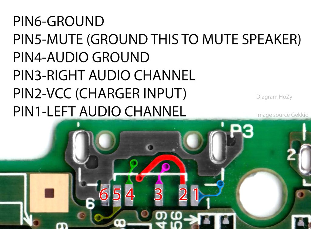
Yeah, it looks like you bridged pin 5 to pin 6(ground), which will mute the speaker: https://imgur.com/a/4oTrmQ3
Hi, need some help figuring out the best way to preserve the contacts of the A/B buttons. Got this board off eBay from a lot and it looks to have suffered corrosion from a battery leak. I was able to clean up the contacts by scratching it off and wiping it clean with IPA. Although I only realised after the fact that you shouldn’t really scratch it off. For now the buttons work perfectly but I fear I’m delaying further corrosion. Is there a way to preserve it in the current state? What’s your advice. Thanks


try vinegar, it can sometimes remove corrosion like this
after that you need to clean it up carefully
Thanks I need to try that. Does the type of vinegar matter? I have apple cider vinegar for example. Also do I rub the vinegar or let it soak over time?
it needs to be clear vinegar not apple cider vinegar. apply it so you have a "dome" of liquid on the contacts and leave it for 5 minutes, then rub it with a qtip/cotton swab and check if it looks any better
once you're happy you give it a clean with IPA to finish it off
Cool, I’ll give that a go later today. Cheers
since there are vias in the area be careful when cleaning off the vinegar - use plenty of IPA and check the back of the board too
I see. Is it ok to also apply vinegar on the vias in that area?
yes. just make sure everything is cleaned off afterwards
Gave it a go with clear vinegar and it definitely helped remove some more. It’s not perfect but it’s better than before, especially the other side. Forgot to take a photo of the other side but it completely cleared spots around the battery contact.

won't last long, there's no more gold on it. for a permanent repair you need a replacement
Hmm I see. I feared that might be the case. Do you know where I can get a replacement? (fyi, I’m in the EU)
Oh wow, thanks!
i have a gbc game that will not boot, likely decayed pins, is it possible to desolder the chips and place them on a donor board or is it toast
If the chips are still good then yes, but you need a compatible board
Is this fixable? (I don’t think it is)

get a replacement board and transfer the parts. it´s fixable
Ok, thanks mate
GitHub
Documentation for my mods. Contribute to N64-Freak/GB-Mods development by creating an account on GitHub.
there you can order replacements
I was wondering if anyone had any idea as to what I could try to test next to see if I could get this cart working again. This copy of adventure island 2 I've had since childhood so I know it worked at some point I can't see any thing wrong with any of the traces and I tried to wiggle the pins and they all seem solid. When I plug it in most of the time I get a fully black rectangle for the Nintendo logo sometimes I get the garbled mess of pixels and 1 very rare time I got the fill logo to come up complete but it just faded to white and didn't load anything


I have tried it on two different sps and a gb all the same results
the pins don't look the cleanest. can you try cleaning them with a white pencil eraser, and follow that up with IPA? (remove the pcb from the shell before doing this, you don't want IPA on the plastic)
oh i did try ipa and also deoxit on it and that didnt fix anything but ill try the eraser
don't be afraid to use moderate pressure to scrub the contacts
the back shows signs of corrosion that are probably from someone blowing into the cart to make it work, so the contacts probably need some extra work to clean them up

hey it worked!
gonna test it a couple more times but it seems to be booting sometimes now
thx
you're welcome
Is there a difference between the white and the pink erasers? I’ve just used whatever I could find when I needed it
the pink ones are almost like sandpaper
Ah yeah I have a few white ones from college I’ll stick to using those, I’m pretty sure I got them for that reason the pink ones would destroy my artwork
playing all earlier today and was fine, turned on this evening and that screen popped up, it did some things and now wont recognise the cart? have reformatted sd card twice, reinstalled files and nothing (the cart doesnt work in other gameboys either). Not too familiar with the cart (ez flash omega) soo i got no clue from here


the left image shows up if you hold R on bootup and it reads the FW update file on the SD card
when you say reinstall you mean you recopied the files or reflashed the firmware
i have old backups, not ones with potentially corrupt files, and got fresh kernal
this is the first time doing the normal reinstall fix hasnt worked
right thats what i meant. you flashed the new kernel?
yeah, the same one that i was using, then that didnt work, so i got the latest and that also didnt work
yep unfortunately thats when you have to contact ezflash or the dealer and see if you can request a exchange
damn 😔 okay hoping wasn't gonna come to that, ty tho 
there were some weird hardware issues and there are some random software issues
there is so much behind the curtain, that at a certain point you have ezflash deal with it
its a lil old

we'll see what they say
if no success I'll just get definitive edition

GBAtemp.net - The Independent Video Game Community
We have found that some users are unable to contact their dealers for warranty after a card failure due to cross-border purchases. Other users are out of warranty by expire one year after purchase.
In this situation, the user may be able to get the card back to work with a simple repair or...
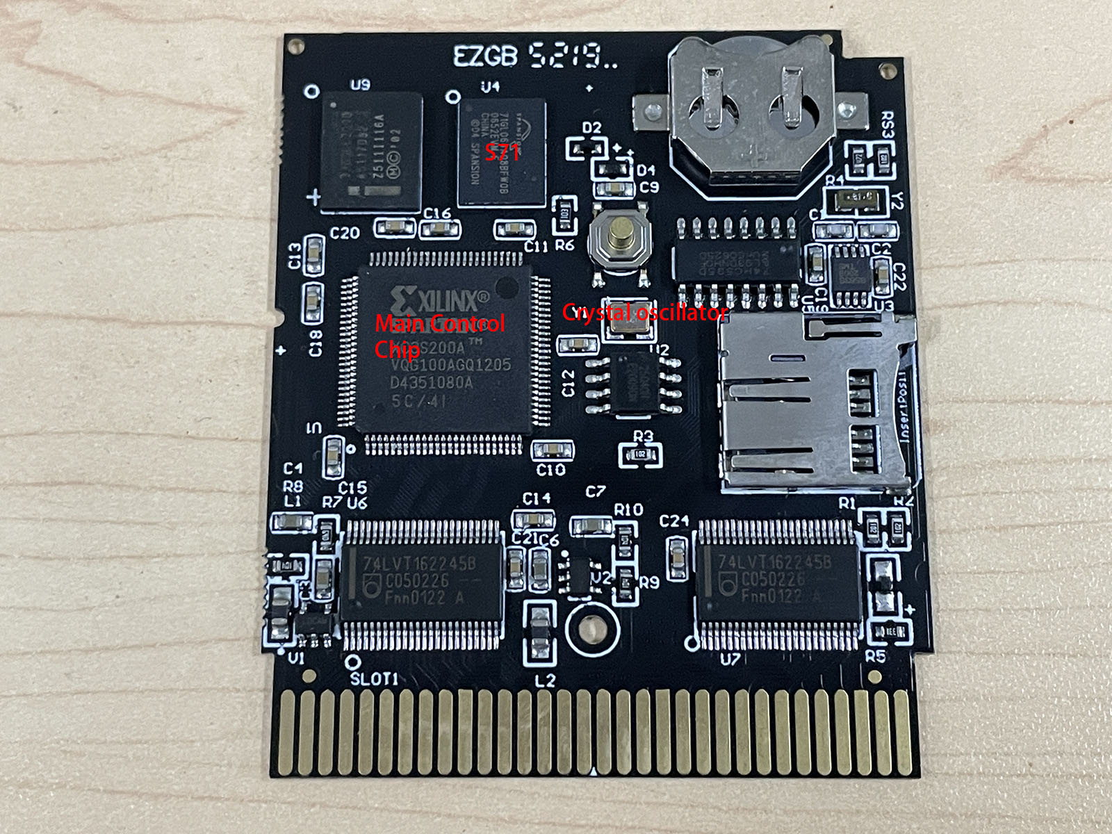
yes but iirc ezflash can tell you if its a oscillator problem before you start blowing components off
ill try find their support email
sent them an email, probably order the osc while waiting anyway, these should do?
https://a.aliexpress.com/_ExF1BAf
yes that looks like it. but do check your electronics distributors in your country. digikey, mouser, farnell, newark. at least get the local service if there is a misship etc etc etc
okiii yeah tyty for advice, will check those before ordering from ae
I have this pocket, its dc input and 3.5mm were severely corroded to the point where the legs were broken off. When I first tested it, I couldn't get any audio out of the speaker or 3.5 likely due to corrosion in the 3.5. So I reflowed the contacts, replaced the speaker wires, and removed the 3.5.Is there a way I might be able to use some jumper wires or something to simulate the 3.5 jack being there? Or does anyone know where I can get replacement parts?


pin4-5 on the audio jack
pin 2-3 on the dc jack
dc jacks are sold on aliexpress. audio jacks are bespoke. but is a shared part with CGB and AGB
Hello everyone! So I’m working on an SP that loads and plays GBA games, but doesn’t load anything when it plays GB or GBC games. At the beginning loading a GBA game I get a few clicks then it plays just fine, but when it loads GB or GBC games it just clicks. I’ve been trying to figure this out. Does anyone have any leads on what may be the issue? Do you guys think it could be the little side switch next to the cart?
thanks
but have you seen that EM1 is missing?
Not till just now.
I haven't worked with a lot of pockets. I will investigate this further. What typically goes there
this is a ferrite bead / filter
Most likely the cart selector switch. Do you have a multimeter?
Skimzor thank you for putting out those MGB boards. 🙏🏼 I just had some made from PCBway for another project.
But yes I have a multimeter. No power supply at the moment though.
You can take the motherboard out of the housing and temporarily tape the battery against the battery contacts to test the cart selector switch.
Does anyone know what could cause the colors to come up like this


This is an ITA kit btw
likely a bad connection to the screen
could be bad connector or needs to be cleaned


plug it in completely
Yeah i did
not on the picture
oh xd yeah I replugged it after cleaning the connectors
It still has the same issue though
It looks like theres something stuck inside it though
you mean this?

Yeah
that's red
can't recognize what it is. could be burnt

Hm
is exactly in the color. there's not much you can do anyway. you could try to get the pins shiny again. folding a piece of paper and insert it several times could remove some dirt
Just cleaned it I was able to get that little ball out
The color displays perfectly now 🙂
Tysm
Looking for help with this AGS-001 not turning on if a battery is below 3.9 volts.
How do I trace this issue in a systematic way?
(Power switch is cleaned. The charging port had ripped pads so I soldered enamel wires to the USB C port. Charging works.)


What’s the voltage on Pin C1 of the power switch? And the voltage of Pin 2 of the power switch?
Does anybody have experience pcb swapping with pokemon gold? I am trying to board swap from an original corroded board to a fabricated one I got off OSHpark
some people have already done this. what would you like to know?
I'm wondering where all the resistors and capacitors must go. I saw some labels on the new board that dont match the locations of the originals
are you sure you have chosen the right board? do you have a link to it?

as far as i remember there is no 1:1 pcb for it. only one extended by fram
yes, it is as suspected. this is only possible if you convert to fram at the same time. https://github.com/Mhouranix1125/DMG-KGDU-10-Plus-FRAM-Upgraded-PCB

GitHub
Contribute to Mhouranix1125/DMG-KGDU-10-Plus-FRAM-Upgraded-PCB development by creating an account on GitHub.
there you can find the BOM. alternatively, you would have to get a game that has the same pcb and then swap parts

is what I'm saying, isn't it?
yea my message uploaded slow
all good
Thanks guys, so what this means, I need a fram chip or something?
I see the materials list, looks like I need a couple more components
in the github link you will find a parts list. you would have to compare this with your pcb and get what you are missing. you will definitely need the fram and the OR gate. the easiest way would be to take over everything with more than 2 legs from your game and then populate the missing resistors and capacitors, then you don't run the risk of mixing anything up
I see, I will also need to figure out where R2 and R3 goes, since I cant see it labelled on the board
Thanks for the advice, I'll report back later if I have any success 🙂


r2 on the old board is r1 on the new board. therefore my suggestion to equip everything with 2 legs according to the new bom

Good call. I see now some of the labels are just really small, much easier to read off the digital image
Heheh I originally soldered all the parts on like the original board, including the battery. It was not pretty xD
Both Pin C1 and 2 on the power switch read the same voltage as the battery.
Does anyone have experience with fixing the black screen on the new 3ds? my buddy was able to boot it to the update menu and run the update but the thing just black screens otherwise. We did a teardown and rebuild of the device but there was no change.
That's a question for #off-topic or the DS server
good day everyone, I am currently troubleshooting a corroded DMG that boots fine into normal carts, but fails to boot to a chinese flashcart.
I get an empty Nintendo logo (I can only see the ©️ symbol lol) and then a horizontal black line appears.
I presume this might be a power draw issue and hence a capacitor change is due, would that be of help?
First thing I will do is to do a proper cleanup of the console and go to work with vinegar on the corroded bits. I also noticed the cart slot to be quite dirty, so I will clean and reflow it just in case.
a
sorry for only 1 letter my keyboard is too sensitive let me try again
power draw is a potential issue yes. can you measure the rails when it powered on, screen connected, and a REGULAR CART (and then also the chinese flashcart) and let us know the voltages? im most interested in the 5V output but measuring the -18V is also interesting if you are using an OEM display
OEM display is in use. The power rails you mean, the ones coming out of the power regulator, right?
yes
also measure the power going in to confirm your batteries are providing enough juice too, why not
makes sense. I will check when I get home. Luckily I have plenty of power regulators to replace this one, should this be an issue
Cleaned up the corrosion, reflowed the cart pins and it works. The cart slot was a mess of tasty blue goo.
A happy console lives on.
interesting that it was that. im glad it's sorted!
Tried soldering iron method and got some lines to work but these gave no signs of life, even if I press them like on this video. Looking for a new display on Aliexpress but I can't find those, just full lcd backlight mod sets which costs 50$+ or I'm just looking at the wrong sellers. Any help is welcome!
I haven’t had a single one of these that I couldn’t fix all the lines… what tip are you using?
Tried with two tips, default and flat
Time for a new screen
any verified aliexpress sellers or here in europe ( checked UK sites you posted here on discord )? should i just do a lcd mod like hispeedido offers? it is arround 50$. i can't find just replacement original style lcd and i think it could be difficult job.
thanks for trying to outsmart me but as i said no one of these fit for shipping to my country or aliexpress links are expired because no one updated this wiki. easiest way to pump your ego is to answer question with discord command. i dont understand you guys. i saw many electronic guys behavior like they know everything and dont want to talk normal. @lucid gull
@placid spade @trim jolt Here are the pictures: First comes the L button, then the R button.


I tested it in my old shell and it fits correctly I think
Here on the new one, as you can see, the left piece under the shoulder button doesn't fit all the way in unless pressured (not sure why)
Here it is with everything in it

When I try fitting the top part, the triggers either fit to the top or bottom, but never to both
Perhaps it's normal and I just need to pressure it a bit, maybe I am overthinking
for mine I had it open like this, with the motherboard in it, and pressed L and R to see where it was "catching"
pushing on top of the button's "hinge" so that it stays in place
Was just trying to help, not sure why you’re getting upset . No one is trying to pump their ego. Responses like these are why some people don’t bother to respond. You could literally search “DMG IPS KIT UK” in the Discord and get your answer.
I actually just tried to do that and after a bit of trimming and bending, the button feels clicky again. But it still doesn't close properly
hmm
I didn't have the same problem of the shoulder buttons not fitting in the shell myself, so not sure
only thing i can think of is to slowly close it and look through the gap and try to see where it "hits" and stops you from closing it
also make sure the trigger buttons are in the right place of course, but i don't think they're wrong on your pic? i don't really remember how it looked
but i remember having to fiddle a bit so that the metal tab was in the right place
i said that i checked everything. i am literally camping on aliexpress trying to find something that fits and just asked if someone know good stores on aliexpress which i can check. sorry it is just misunderstanding
I think they are in the correct place, yes! Now that that's fixed, there seems to be another issue. The parts fit well in both parts of the shell, so I will see what it is... Thanks for the help, I will report back once it's solved 🙂
Well, there seems to be some kind of contact point that is preventing the shell from closing on both sides. The original shell closes properly with everything inside, so I am unsure of what's wrong
only thing that comes to mind would be to place like a piece of paper between the two halves of the shell
press hard, and maybe the point where it contacts will leave a mark
no idea if it would work
and if you can see what point touches you can cut or file off a bit of the plastic
Oh I will try that!
Excuse me I’m trying to pump my ego ☝️
Hello all, I’ve recently been looking into fixing this DMG-01 gameboy that I got off of ebay that wouldn’t power on. It was pretty corroded on the inside

After some continuity tests, I was able to figure out which via was causing issues, and wired to an adjacent pin, and to my surprise, that resolved the power issue
Whenever I did some testing, I noticed I couldn’t see anything on the screen
However, I could see some activity in the screen when I’d power off or power on the console. Like, temporary horizontal lines and such, so I could see that there was some life left in the screen
After playing with the contrast, I could see a barely visible rectangle sliding across the screen, the boot logo. But baaarely visible

To isolate whether it was a power issue or not, I tried a screen from a completely working gameboy, that one seemed to work as expected, so afaik it isn’t power related, and the issue with something on the board that has the screen


I tested 3 of the capacitors so far, and those seem good and I also tested the contrast potentiometer and that seemed to be working as expected
Before I test those other capacitors, is it worth going through the trouble?
As in, would one of those remaining four capacitors cause an issue like this?
I wouldn’t want to go through the trouble of desoldering those if they aren’t worth it, and given 3 of the capacitors are fine, I’d like to believe these are too
This is my only lead, I guess I don’t have much to lose at this point

fixable or rip?

This is RIP, sadly
Is this normal behavior for the original GBA? Diagonal directions are way stiffer and by simply tilting the d pad in a circle you can’t really trigger them. You really have to press it. Contacts were cleaned.
Hi all,
I have 3 gba sp 001 boards and screens. One of the screen's front light keep getting dimmer and dimmer during playtime and it's like about 100% off at around 15mins of being turned on. I swapped them all and tried different combinations, so far, only the screen seems to be bad as with whatever board I put it with, it still happens. I tested the first two contacts of the ribbon cable and the two soldered pads(front light+-) on the back of the screen and there's continuity. When the screen light is fully dimmed, no matter if I press the brightness on/off button, nothing happens. But while it is functional on the first few minutes of gameplay, and slowly getting dimmer, I can turn it on or off, but nothing past the slightly dimmed stage. If I turn the gba off, let it rest about 15mins, it is back again to full brightness. What else can I do?
I just tested the pads behind the screen. On working screens it is almost consistent to 3.3V, my bad screen starts off as 3.3V and starts going lower and lower 3.299, 3.298, down to 2.7V.
Hey all, I'm finally getting back to trying to fix my MGB that had issues turning on after I modded it.
At first, it worked fine, but the next day, it would work inconsistently. I thought maybe it had a dirty power switch, so we desoldered it and cleaned it. After we soldered it back on, it still wouldn't turn on, this time ever.
For months we assumed that the fuse blew, but today we tested the fuse with a multimeter, and it appears to be fine. What else should we test? What could be the issue?
I'll post pictures of the board in a sec
So we tested both sides of the fuse, and it outputs 3.1V on both sides when the console has batteries connected.


What voltage do you get with your probes on these pins?

Nothing
And this is while powered on? If so, that means you’re not getting the expected 5V output. You’re getting continuity on the fuses?
The two sides of the fuse circled in red have continuity. The two sides of the fuse circled in blue do not

Unless you wanted me to test continuity between the two fuses
Also yes, it's powered on
F1 is your only system fuse. if it doesnt have continuity then its blown
Well, that solves one part of the mystery
But how did it get blown? I have a new fuse handy, but I don't want that one to get blown too

The exposed wire?
I thought it could be that, but I didn't want to make assumptions without checking with this server
I always say, work backwards. If the fuse is blown, replace the fuse, remove any mods you added prior to it breaking, test that all is good, then re-add the mod and see if something different happens.
Alright
Does this hole with traces coming in and out do something?
I'm trying to troubleshoot an emerald cart that won't be recognised

No, but some of that other wear might be the problem - those ground vias look rough
Can anyone tell which ones are real and which are 3rd party

Never mind I figured it out
add it and everyone will benefit
Does anyone know where the test points for CP2 and D2 of the AGB are? I'm still having some power problems after doing a tant recap, and I wanna make sure the solder actually welded to these pads. Currently doing a power switch cleaning.

in the upper circle it looks to me as if there is no longer a pad underneath the component
There is, the cap is just so big that it covers it.
Part of the reason I can't tell if it welded...
do you have hot air or just a soldering iron?
Soldering iron only
with the soldering iron, all you can do is use a lot of flux and try to heat both pad and component with fresh solder on the tip. without being able to touch the pad directly, you must somehow manage to heat it over the component. this is not ideal

Okay, so it looks like it's connected to the ground plane, that's good to know! Ty.
Yeahhh I got CP4 doing that, but it is indeed tricky.
Plus, as expected, my power switch was kinda dirty.
both negative sides of the tantals should be connected. you can check this
I seem to be getting continuity, might just be the power switch after all.
But, thanks for helping me check my work!
Yeahh right off the bat, the power switch isn't so sensitive anymore. Strange how it worked just fine before I changed the caps, but now it's picky about the cleanliness of my switch.
Is the fix the same for white lines and black lines on a DMG screen? iron on the flex cable? Or are white ones an issue from another component?
This is the line
#gameboy message
both are solved by using the iron on the flex, but vertical lines are more likely to get sorted. Horizontal lines are harder to fix because the surrounding plastic melts easily and sometimes can kill the screen for good
Nice to know, thanks 👍
I won the auction so I'll see if I can fix it once it arrives
good luck. If the screen is not fixable a good IPS mod will do wonders 🙂
Will an IPS modded gameboy pocket(powered by disposable batteries AAA)play with an everdrive gb x7?
Hi all! Question here about power in my GBC. I have installed in it a FP IPS (I think it's the previous model) and also a 6V capacitor and RetroSix's Clean Power GBC. I also run a EZ-Flash Jr in it. Now, it plays alright most of the time, but in some games it just turns off by itself. I don't understand why. Any ideas?
Could be a number of things, having pictures of your install could help identify the issue

also the board itself works it's just the jack i think
you wanted to know if you can buy it new, this is the answer
yea and like 3 other questions and also i specified my country but ok! nvm
too bad you deleted them. Now you'll never get an answer
Just build one with aftermarket parts, cheapest and easiest
Kamicane's works, I think
what childish behaviour 🤣
It does - needs very few components for OEM amp too
Looks easy enough

For OEM you only need the jack part, u2 and r5
still having this problem with my GBA SP: #1006398521576005663 message
got these results with a multimeter #1006398521576005663 message
but i have a question now, that being would a voltage regulator help at all? my friend told me about it and i was thinking that it might help with all the mods i have with it; i've never heard of one of these before either so yeah
here's a link to the one my friend told me about: https://www.retromodding.com/collections/game-boy-advance-sp/products/game-boy-advance-ags-101-voltage-regulator
oh it seems like a may be stupid as well, but that voltage regulator is for GBA systems using GBA SP screens if i'm reading it correctly
still, my original issue still is a silly
Hi, I run with this setup. Yes it will. I highly recommend getting rechargable batteries though, you will burn through disposable batteries faster than a Nintendo DMCA takedown.
Ohh thanks! i'll keep that in mind
Hello community. Can someone let me know if this is safe? I want to make sure the battery won't overcharge and blow up. I combined a GBA dock mod with a rechargeable battery. I added in that circuit board cause it has a charge protection circuit. Any opinions are greatly appreciated


For safety reasons, please consider using rechargeable AAs. They last longer too!
this is also a #modding question as your game boy isnt broken
the charge module you used is not efficient nor modern, but very very cheap which is great for cheap modders/sellers
you also have a huge exposed lead off the diode that can ground itself very easily
Trying again to fix my MGB. I manually touched the ends of the new bottom fuse to the connection points, and it immediately got hot to the touch, leading me to believe something is being shorted.
Last time I talked about my issue, it was suspected that the short was caused by the exposed metal on the purple wire connecting the screen kit to the MGB's motherboard (second picture). However, it doesn't appear to currently be touching anything, unless I'm missing something. Is there another thing shorting it, or did something about the screen wire fly under my radar?


Update: The fuse no longer heats up when the screen ribbon is disconnected from the board, so I guess it really is still that wire.
But what part of it is causing issues? Is it the end soldered to the power switch?
The via under the point where the wire is soldered to has some solder in it. Could that be it?
We removed the solder from there and things seem to work now. Now we're gonna actually solder in the new fuse.
Anything else we should do just to be safe?
Nvm, after soldering the new fuse in, somethings still wrong...we managed to turn off the system before it completely blew again
You probably should reflow that joint with flux, it looks like a cold / dry joint
Are you using lead-free solder?
Also curious if you've cleaned your power switch
Yes, the power switch has been cleaned. Yes, the solder is lead free.
Do you mean the joint on the left or the right
Ideally both, neither looks particularly shiny. That's the problem with lead-free solder: it's melting temp is higher so it's much easier to end up with joints like this.
The area surrounding both joints looks burnt from the iron.
After reflowing the right joint (the left one was on a pad which I didn't want to risk burning), we're having a strange issue where the system turns on, LED and sound, but there's no image on the screen. Our multimeter seems to indicate that there is power getting to the screen's ribbon, so idk what the issue is
At first the screen did turn on, but the only thing we did differently in between it working and not working was covering the front of the board in kapton tape
We stopped working on it for the night. If anyone has any ideas on what this new issue could be, let me know.
FWIW, everything seems to work fine if we put the OEM screen back entirely.
hi all, is there any way to get this IPS screen working or is it toast?

it was working just fine after i installed it but it wasn't aligned properly, so i opened the gameboy back up to adjust and when i put it back together it's looking all wonky
That looks damaged, I'm afraid. Did you try reseating the ribbon connectors? Luckily the displays themselves aren't the expensive part so if you need to replace you're probably only out $10 or $15.
i jiggled around with the ribbons a few times here and there but nothing has changed
dang I wonder how it got damaged so easily then
not yet no
i was adjusting it before sticking it together
it's my first time with one of these
so it wasnt sticked down at all
nope - i plugged it in, turned it on and saw it was lopsided, adjusted it, went to double check it was level
i was debating between sticking it or not because i tested it in one of my childhood gameboys
Hmm well what you're describing shouldn't have caused this, but if you tested it first and it didn't look like that that's really the only explanation.
yeah, unfortunately that seems to be the case.
where can i get these $15 displays though? cheapest i'm seeing is closer to 60 on ali express
is that the 2.45 or 2.6 screen
2.45, to fit OEM
np
well i'm kinda glad this happened then because it won't be too pricey a fix it seems and it gave me reason to seek outside help
i've kinda started this game boy modding journey on my own so far not knowing much about any of this stuff
Is the GBA quieter than the GBC, or should they be about the same volume? I’ve got an FP speaker in both
Might depend on mods, power switch, and cap health. I think the wattage is the same for both speakers so in theory, same volume.
But a Bucket Mouse poco is going to be louder than a regular CGB due to the amp so there’s that too.
Stock amps, new caps on both except
for the big cap on the GBA because it felt glued on and I didn’t want to mess with it.
What could cause an MGB with the FunnyPlaying IPS kit to not have any image on the screen?
The LED turns on and there's sound, but no video
Provide pictures of the install
#1006398521576005663 message
Actually there's been changes since I took that photo
Ah
Most notably we redid the wiring completely
Ok, here's the new install. Let me know if you want pictures of other areas.
Should clarify, the fuse is no longer blowing. Like I said, it turns on but there's no video on the screen. There is video, however, if the OEM screen is re-installed.

Does the backlight turn on?
No. It's just black
can you post photos of the ribbon and the solder joint for PWR
Which part of the ribbon?
Actually, taking a closer look at it, it seems that around the joint you asked for a picture of, the ribbon has been damaged from the console constantly being manipulated. Would I be correct in assuming I need a new kit?
Probably just a new ribbon—but I think it might be a good idea to get a soldering practice kit and some leaded solder.
So
Just installed usb-c mod for gba sp
it charges up the battery just fine
but
it doesn't turn on
what can I check to diagnose this problem?
(also using FP battery mod)
Please post pictures of the install

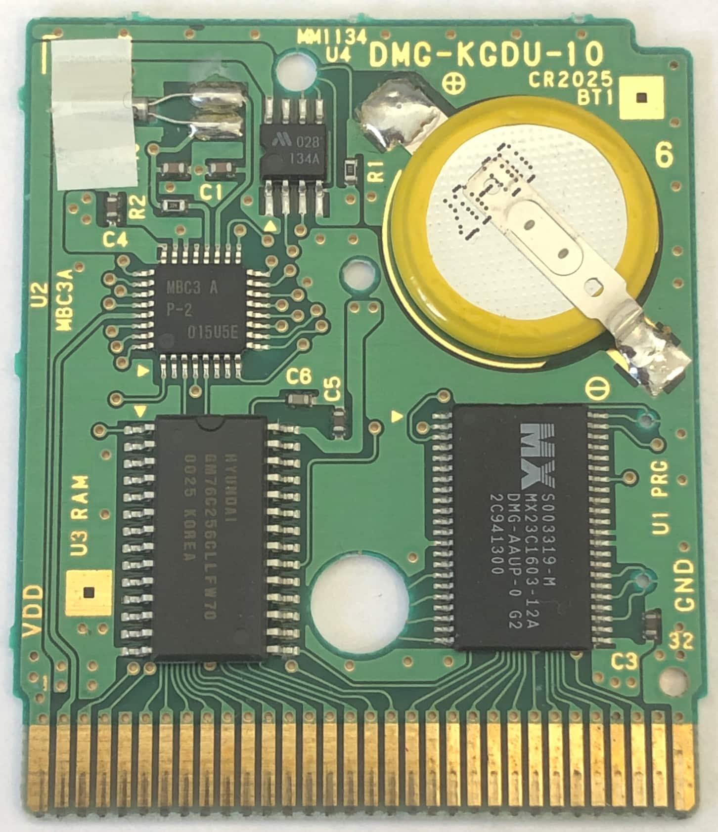