#Troubleshooting
1 messages · Page 3 of 1
 I'll have to try tomorrow(beddy bye time), thanks :)
i know this is a 2.6 and yours is a 2.7 but i hope this helps. there is noting on R16 and with my fluke 114 R7 is .5-.7ohms my leads measure .4ohms. i really dont know what it should be

thanks Mike, I appreciate that. I only had a 2.2 version so I couldn't test it myself. Let me see if I even have such a low ohm resistor
I have an SP that I’m trying to open up, and I’ve gotten the 4 corner screws out, but I can’t seem to get the flat screws out (the one that goes under the battery and the one that goes under the cartridge). They’re not stripped, I just can’t get either of my Y bits to catch.
These are the screws, in case this does count as stripped.


Y00?
If I have a Y00 it’s missing, I have a Y2.0 and Y3.0
thats way too big. Y0 is already kinda too big
Is this trace busted now?

looks still connected. but you should fix it with soldermask for example
Should that trace be connected to plus side of that capacitor?
it is no longer? here you can see the trace. its connected from the positive side of the capacitor to pin 8 from u4 and one side of c55

then electrically everything is fine. but try to fix the loose pad. soldermask ist cheap
I tested it wrong, it’s actually busted
Dug out a multimeter to test properly…
Any idea if it’s fixable?
If I add a wire?
youre asking internet strangers to judge your skill
it is fixable, the board scan above shows the trace
Lmao I fixed it for a moment by adding a wire to C55. But I broke it again trying to reposition the wire and pulled C55 out

3D printed battery mod housing and the battery doesn't fit in it, but the housing is perfect in my GBA SP
is it
A. battery misshapen? i have some problems with it, can't keep a charge
B. something wrong with the height of the print
C. i am stupid
D. all of the above


A/B. prints are inconsistent, pouch batteries are inconsistent.
trim and sand the print or just dont use the print
all right, thankers
i have access to a 3D printer and i thought i might as well use it lmao, so i wanted to try it out
Alright I feel like I'm going crazy but I'll ask about this in here just to see if other people notice it. I got my funnyplaying ITA Laminated Kit and installed it, everything's working. I've configured it with the potentiometer using that aging cartridge flicker test and everything.
It's much more noticeable in person, but look at the bubbles in the ground when the screen moves, specifically the really basic ones. Notice how they sorta go dark for a second when it starts scrolling? For me, in person, they stay dark as long as the screen is scrolling and go back when it stops. I've described this as a "shimmering" effect but I'm really not sure what it is.
I've noticed it a ton of times on different screens and devices, I was hoping a perfect little ITA wouldn't have this issue. Is this just an inherent issue with screens and scrolling? I notice it on my IPS too. Is it even a real thing or am I just going crazy
If my Pocket won’t power on unless I spin the batteries, but the battery contacts have been cleaned, is this something where the answer is gonna be “did you check the power switch” or is there something else probably wrong?
Batteries are tested and working
Power switch cleaning is the next step
I was afraid that was the case. It’ll have to wait until Saturday at earliest then, that’s when my iron arrives.
be careful with the power switch parts after you open it, they're easy to lose, speaking from experience
Trust me, I won’t. I’m ordering that tonight, along with a mat and stand. It’s just that I won’t be able to provide further commentary on what I find until it arrives.
*wont forget
I realized replying to “don’t forget” with “I won’t” and replying to “please practice off the GameBoy” with it are two completely different meanings
Also pocket switches are a bit harder than agb. So take extra care anyways.
I haven’t touched the switches to any other device of mine, when I get that practice in I’ll check the switches after.


Correct.
Not even with another screen?
That'd be replacing rather than fixing, but yes, you can replace the screen
Mind that you'd, of course, have to replace the whole screen
Please consolidate your comments into one post. If you're based in the USA you can get a new backlit screen here https://retrogamerepairshop.com/collections/gba-sp-displays
If you're looking to replace it with the same type of screen (a frontlit 001 display) you'd have to try your hand at either AliExpress or a reseller market (eBay)
Once you've been in this Discord for 30 days, you can try #1049401311101206649 to see if anyone here has a spare display
Sooo, a new backlit screen should be the way to go isn't?
That's my recommendation
Just bear in mind your own skill at modding, and whether you think you can do it without destroying your Gameboy
I am not in USA, I don't think the Marketplace would be useful for me
I am gonna ask my usual shop is they can do it for me
It is hard?
We had a user just earlier today who failed to even open their Gameboy
I can Open the cover to get the battery at least
It will be quite more involved than that.
But for both screens you need the same procedure isn't?
Here is a list you can reference for screen kits
If you’re at all uncertain I’d take it to your local shop that handles these sort of things.
My gosh , they are like 60 bucks wow.
If is the same procedure as a normal screen, I know they can do it in my usual shop
There’s usually a solder point but basically yes it’s about the same as replacing it with another similar screen
Got it, but is too expensive for me at the moment... I rather get the normal screen.
Btw, a good site to get the batteries for the GBA SP model 1
The one that doesn't iluminate the whole screen
The style of the first picture or the second?


First picture
The SP that doesn't iluminate the screen really well
I actually own 3 GBA, The original one, the SP model 1 and SP model 2
https://www.zedlabz.com/products/replacement-battery-for-nintendo-game-boy-advance-sp-by-helder-800-mah-zedlabz here if you’re European.

ZedLabz
Restricted product - Lithium battery transport is restricted and we can only ship to a limited number of countries, refer to our delivery page for more information or add to cart to see if this can be shipped to your location.Features: - Custom replacement battery cell for Nintendo Game Boy Advance SP console. - NOTE: Compatible with Game Boy ...
Latino
Ah well then this https://retrogamerepairshop.com/collections/gba-sp-power/products/gba-sp-game-boy-advance-sp-rechargeable-850mah-lipo-battery-mod-by-makho?variant=32212802109514 is probably better

Retro Game Repair Shop LLC
Just remember...The red wire wire gets soldered to the positive (+) and black wire gets soldered to the negative (-) Don't screw it up! Makho's test resultsTroubleshooting guide Users have reported a battery life of 8-10 hours on average. Now you can be just like Makho with this Game Boy Advance SP battery mod! Stop
But this may not come pre soldered someone will have to say so I’m not sure.
That battery how much it goes by in AliExpress?
Probably isnt on Ali.
Or Ebay
I hear there were batteries on AliExpress, not the same model as the one you showed though
I guess
RGRS doesn't ship to latin america
I mean you can search for them.
But it is a good bet?
What is a good bet
Don't worry, courier
The AliExpress ones
I mean I bet they’re on there. Quality is another question. I’m not big on using aliexpress.
Funnyplaying sells similar batteries I think
That I would trust
How much
meh I think they're out of stock, just checked it
maybe try searching them on Ebay, idk
Ebay, got it.
Guys got a question
I decided to go buckwild with tuning up my GBAs
So a good site to buy retroiluminated original GBA screens?
And does it require soldering?
Some do
This list should mention which do and which don't
March you are a lifesaver, thanks a bunch!!!
I noticed the guide is for the GBA SP, I was looking for the original GBA this time around.
same wiki has information about the original GBA
this sounds like youre asking for #modding advice and not #1006386432065155083 a broken game boy any more
please move over to #modding to keep the channel available for broken game boys
Got it, apologies.
got access to a multimeter and am trying to test the continuity on my GBA SP's charger port and want to make sure i'm doing this right, i'd have one terminal on PIN2 and the other on the outer housing of the port? if not, where exactly

Testing continuity determines whether a circuit is complete or broken. Are you trying to test the voltage coming into your charging port? If so, then you'll need to have your multi-meter in the correct mode (DC V) and have the red probe on Pin 2 and black probe on the shielding.
i believe i did this right, and this is the read i got which i believe is in volts

Looks like you are in diode mode.
And it looks like you have the same multi-meter as me
i did not realize how shotty the picture came out

yeah that's the one i have lol
should i have my charger plugged in
yeah with the charger it gave me a reading ~5 V
only one way to find out if everything is good
I'm assuming you have charging issues with your SP? Have you gone through the troubleshooting steps in the wiki?
Game Boy Resource
The place for information and tools for Nintendo's Game Boy handhelds.
yeah and yeah i have
i believe with this multimeter testing i have done everything besides buying a new charger
but i narrowed to down to it not being my charger or battery, because my other GBA SP is able to charge the battery just fine
i did clean the pins inside up a bit too
What happens when you plug in the charger? Does the charging LED (orange) light up?
And it stays lit?
yeah
and whenever i tried to change the brightness on my IPS screen, it would die immediately
Can you open up a new thread and post pictures of your motherboard? Both sides. I'm curious now
yeah sure
but i'm not going to be arsed to desolder the brightness control >:(
ok trying to make a post just put me in slowmode and didn't actually post anything

did you make and delete a post? cause that will not remove slow mode.
then I leave it to the mods
and restarting my client keeps what i entered and resets the slowmode but then does the same thing when i try to post it

if you are in slow mode there is nothing to do but wait sadly
I was just trying to help you figure out why it happened
i think discord is just being discord again and not working

doesn't seem to put me in slowmode for real, but then doesn't let me actually post something either
I can't enter any of the forum posts so something is up
can only enter the ones I am following since they are under the channel on the list, but can't select anything in the posts list
awesome
can't even make on in a server with no slowmode
they're just broken right now
hmm. fully closing discord helped
not for me it seems
i'm just gonna put this thing back together and try killing it and shit
@remote bobcat if you're still interested in my motherboard, just let me know and i'll send them here or in DMs
just post here


How are you verifying that your battery isn’t charging? Can you probe your battery and give the voltage?
well i knew it wasn't charging when i plugged it in while the battery was in GBA 1 and after some time, it was still red and couldn't handle changing brightness and then it working perfectly fine in GBA 2
So the power LED staying red is a symptom of a dirty power switch. Have you cleaned the contacts inside the switch? Changing brightness shouldn’t have anything to do with charging
Could be a pinched wire or short somewhere but I’m not knowledgeable on GBA SP IPS kits and their brightness controls.
i did clean the switch yeah and it did the same thing
Desoldered the shielding and scrubbed the inside?
i just said that as it was still low and thought that it couldn't handle it going to a higher brightness with more power to send
yop
and my wire seems to be fine
What’s the voltage coming out of the battery?
That should be higher than the low battery voltage cutoff. Can you plug in the charger and let it sit for 10 minutes or so. Then take the battery out and measure voltage again
well the battery isn't dead as of currently
is green in a GBA
you still think i should charge it?
is this a new battery?
Plug it in the SP with the ‘charging’ issue and plug in the charger and let it sit for 10 minutes. Then pull the battery and measure the voltage again. If the charging circuit is working, the voltage should be higher than the baseline of 4.033V
all right, got it
it is 4.038 V
it definitely went up, though i'm not sure how much it should after 10 minutes
could've been of a result of cleaning the port itself and such
i am just gonna let it charge more
4.033 might be at the top end of the voltage range for the battery. Do you have a less charged battery to test?
One at like 3.8V
yeah, i have one at 3.829 V
this is the stock one that came with this AGS-101
(which is GBA SP 2, GBA 1 is AGS-001)
should i charge that one for 10 minutes?
In the broken charging SP and see what the voltage is after 10 minutes. Trying to isolate whether or not its actually the charging circuit
figured you mgiht say that so i did indeed do that
3.842 V
so it looks to me like i fixed it i think?
I don't think it was broken in the first place
Still have the issue with the red battery indicator and the brightness change right?
i'll have to kill the battery to test that
so i will do just that lmao
will report back o7
well i did some testing to see if it charged and these were my results with both systems
GBA SP 1
starting voltage: 3.390 V
after 10 minutes of charging: 3.414 V
GBA SP 2
starting voltage: 3.933 V
after 10 minutes of charging: 3.505 V
though, after the very last test, one of my wires broke so yeah :)
both my battery's wires broke, and now they're too short and i messed up shrink wrapping them
i'm just gonna replace my thing with a USB-C already
hey is it normal for my gba sp to last only an hour on a full charge?
Im using FP IPS V3.0 with a new battery from OSTENT 850 mAh on amazon.
I typically play with full brightness and sound on low.
I get around 40 mins of playing before my battery turns red.
thanks.
That's not normal, but a few things
- That battery likely has less, if not far less, capacity than advertised
- Are you using a flashcart? Those will suck up more juice than normal games
- Have you desoldered the shielding on your power switch to clean the contacts
sorry forgot to mention i am using an everdrive mini
I havent tried desoldering the shielding on the power switch to clean it bc i havent felt comfortable yet
Between steps 1 and 2 that's where most of your juice is going
Now, when it turns red, that normally means it's about to die
But between all your mods and, more importantly, your dirty power switch: your Gameboy is likely going red far before it's actually about to die
If I had to hazard a guess, I'd say it's turning red at about 40% remaining battery
alright thanks i appreciate the feedback, ill eventually clean out the power switch sometime later

Yeah no.
I love this place
I almost did something stupid
Soo..
Mmm
Is AliExpress a good place to get batteries for my AGS
001?
Instead of posting pictures at random to know if they are good or not
I rather listen to you guys, where do you buy batteries
Game Boy Resource
The place for information and tools for Nintendo's Game Boy handhelds.
It’s really worth it to invest in a solid proven battery
I agree
Ok , I saw the resources , so Retro game repair shop is the same as Funny playing right?
So Funny mades and retro just sell it at USA
Any thoughs on this battery?
Retro Game Repair Shop LLC
Just remember...The red wire wire gets soldered to the positive (+) and black wire gets soldered to the negative (-) Don't screw it up! Makho's test resultsTroubleshooting guide Users have reported a battery life of 8-10 hours on average. Now you can be just like Makho with this Game Boy Advance SP battery mod! Stop
Looks like it needs soldering
it’s the highest capacity battery
https://docs.google.com/spreadsheets/u/0/d/19XQH36IGooG8Mt1FNpmsqI8DTvbR6hicbCa4-d_VVAs/htmlview
If you don't want to solder you can always grab one of these https://www.retromodding.com/products/makho-game-boy-advance-sp-battery
Retro Modding

I believe it's the highest capacity drop in replacement on the market
Just what I was looking for
So the SP 101 and 001 model use the same battery from the look of it
Yes
I am learned a lot here, thank you guys
My ags 101 has no sound and I can’t for the life of my figure out why, I tried several speakers and cleaned it quite well
cab you post photos of the mod and any troubleshooting steps that youve done
It’s just a normal motherboard, but yea one sec


It was missing a capacitor originally, so I tried to take one off an old motherboard and soldered it onto this one
Cold joints?
bad solder job
i would not call this motherboard clean there is corrosion on the memory so i would bet there is corrosion in the volume wheel. you can measure the resistance on the wheel and compare to the schematics
https://github.com/Gekkio/gb-schematics/blob/master/AGS-CPU-11/schematic/AGS-CPU-11.pdf

GitHub
Game Boy -related schematics. Contribute to Gekkio/gb-schematics development by creating an account on GitHub.
Is their a multimeter or something you recommend to check, I’m not sure of a good one to order
anything youre comfortable using with all the functions you may need in the future
Ah ok thank you, if their is corrosion inside the volume wheel will IPA fix that or will it need to be replaced do you know?
replacements are listed in our parts sheet in #998610706133954830

You can run a jumper wire to that trace/via

What exactly are you trying to do though? The board looks pretty corroded
It works and everything, just no volume so I wanna see if I add a capacitor that was missing, it that will fix the problem
Hello everyone,
I'm seeking some guidance on fixing the sound on my Gameboy Color. Here's the rundown of the issues I'm facing:
When using the headphone jack, the sound output is fine, but there's a minor hum/hiss in the background.

The built-in speaker doesn't work at all. I've tried replacing it with two different new speakers to no avail.

The volume wheel acts strangely when headphones are connected. Although it mostly functions, it does so inconsistently.

I've already cleaned both the headphone jack and the volume wheel thoroughly.
Any suggestions or advice on how to proceed with these repairs would be greatly appreciated. Thanks in advance!
Hi. This is HoZy's CGB audio issue troubleshooting guide. It sounds like Pins 4 & 5 of the headphone jack aren't continuous so the CGB thinks that headphones are still inserted and therefore disabling the speaker.

4 & 5 appear to be continuous. I reeallly appreciate you posting this though
New problem. Same game boy.
When I screw the back of the shell on the display only appears black. seriously. this doesn't happen when the back of the shell is removed. Im perplexed.
i loosen the screws: no problem
I tighten them: problem
Pics
what do you want to see? the black screen or the loose screws?
im asking unironically haha sorry im new to this


Does it do this on other Gameboys?

Like, someone you can send it to to have it repaired?
I always see an eBay listing of an advertisement of this guy who you can send in a GameBoy for him to fix, never tried it though
If you’re located in the US I can take a look at it.
rip im from downunder
Dang. If you really wanted to send it it would just take longer to ship back and forth and it would be more costly.
Hello! I had some battery leakage on this GBC but after cleaning I see that the solder was eaten. Should I replace the capacitor or resolder it? Any way to check if it's still good?

If the cap is original replace it.
looks like you are missing a pad.
I think it's original. Maybe I should replace all of them?
have you soldered before?
if you are new to soldering you are likely to break it more by going around replacing caps willy nilly.
Ah yeah maybe... the cap is still attached to the board though
I am new, I just did practice kits and changed carts batteries
You may want to think about commissioning this one. Someone skilled will make quick work of it
I actually want to learn :)
That's why I have practice kits
you can practice desoldering on the kits as well. solder them up, remove everything, then put it back together to see if it still works.
Do you have a hot air station?
If so, you can remove the cap to see the real damage underneath. It's possible the pad is salvageable and just needs a good scrub with a fiberglass pen or a steel bristle brush
I don't have a hot air station unfortunately.
Removing a surface mount capacitor with just an iron is a fast track to ripping pads
While it can be done, it's best to hold off for now
You are right, I will wait until I have the right tools.
In the meantime, can those mounted capacitors be checked with a multimeter?
no. capacitors should not be measured while installed
you can meter the circuit on both sides to make sure the traces arent damaged but nothing more than that
there are board scans in #troubleshooting-archived
measuring continuity is a good idea IMO. flux + reflowing with fresh solder helps clear corrosion too
yes i agree. flux and the iron alone might drive out some of the contaminants on the joint to at least let you see the joint
and visually you can determine if the trace is broken
Do you mean by testing continuity?
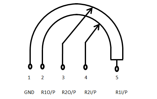
Looks like something is missing on mine 👀

refer to a schematic or sanded PCB scan to see where those pads connect. use a multimeter to test for continuity between the pads and the traces they're supposed to be connected to. that said sometimes a multimeter will report continuity even though the connection is not good enough for the circuit which is why reflowing helps

Pad 4 is NC so it doesn’t connect to anything. So no, not a reason you wouldn’t have sound
That’s what I saw somewhere else too, I’m not sure why their is no sound then
I just replaced the capacitor too hoping that would be the fix
there are schematics pinned in #troubleshooting-archived
its for a CPU-11 but the audio circuit after U3 is largely the same
I have a GBC with no power (just a quick flicker) and its power regulator doesnt give 5/15/13V and D2 has 2.6V instead of 0V. Do you know what could be the problem?
how are you measuring D2
because that is a reverse polarity protection diode and it should not be seeing voltage at all. do you have the batteries or your battery clips on backwards?
I supply 3V with a external power supply through its terminals in the pcb and it should show 0v I think if I put the negative terminal of the multimeter on the top side of the diode and the positive one at the bottom (that is what i see on a yt video and I have also checked with a known working pcb)
can you post a photo
Of the diode or the measure?
your setup with the power supply and how its hooked up to the game boy


do you need to set your current limit on your supply
because it looks like you have it set to zero

looks like you have to set the current limit
I dont understand what you mean exactly (maybe because of my language). Do I have to set a limit voltage?
im asking if you know how your supply works and if you are using it correctly
because im not familiar with that supply and the one that i use requires to set voltage and amperage limit
this is meant

ah ok, yes I set the voltage before I plug the terminals in the gbc pcb
you have voltage and amperage. if it´s 0.00A then no juice is going to your game boy
on some psu you need to short plus and minus and then you can adjust the max amperage. but you should take a look into your manual how to setup your psu
about amperage, I dont change it and it works with other (known working) pcbs

ok i will try. Anyway this is what the pcb does with batteries and also with the psu
my first thought was a dirty power switch but I cleanned it with no luck
Can you check if any of the power rails are shorted to GND?
Following the guide I have no 5V/-15V and 13.6V in the power regulator (as I said in my first comment)
are any of them shorted to ground
nope
And fuses have continuity?
I saw also (in the YT video I mentioned before) in U7 I should have 3V between pins 3 and 5 (I dont remember exactly now) and when I measured I had 0V
yes
and batteries are fresh? :D
He's powering from a variable bench PSU
are you following the guide that i posted?
Oh missed that
Yes
I think he's got some corrosion bubbling underneath the mask

yes and all the corrosion on the vias (holes)
how does the back look?

there are schematics pinned in #troubleshooting-archived and we are working to move the board scans to the wiki
but you have to clean up the corrosion and make sure the traces arent damaged. you might have a broken trace on VDD5 or VCC since that is the area that you have corrosion on
yeah. do a thorough cleaning before you prod anymore and add power to the mix.
and maybe is more corrosion than I can see
is there replacement for the power regulator?
Several

This Video Games item by FroggoCustoms has 43 favorites from Etsy shoppers. Ships from Seattle, WA. Listed on Apr 4, 2023
Note that you won’t be able to use the OEM screen with almost all the aftermarket power regulators
One thing you can try is desoldering the OEM regulator and attaching your power supply to VCC to see if the regulator is outputting the correct voltages
Why is that?
OEM color screens need the 5V, 13.6V and -15V rails. Aftermarket regulators usually only have the 5V rail available and therefore can only be used with IPS screens
I have done and yes, apart of the pcb it shows the correct voltages so it might be right
My problem is I am not good at all with the measurament. I mean, if I get 3V from battery or psu to the regulator but it doesn´t give me the rest of voltages, there should be a trace or component between the 3V line from terminal to regulator that is bad right?

So I’m confused. You desoldered the regulator and it’s working correctly outside of the rest of the PCB? When attached, it doesn’t output the correct voltages?
Yes, that is
Oh and this

Sounds like there’s something shorted to GND on the power rail line. Can you check C32?

It has just one side bridged to GND
Regulator looks like it’s working. So there’s an issue on the side of the power rails. You’re going to have to probe around. Use the schematic as your guide. Clean up the corrosion first as well.
The thing is, when do you know the corrosion is cleaned properly? Because the line with more corrosion (in my pcb) is GND (I think) and I have continuity in the hole area even the capacitor (c47)
this

Did you poke around and check the 5v points i marked? Are they shorting to bat-?
They are not shorted to bat-
You can pull electrolytics in case one is dead short
I dont get 5V in these points in fact, I think I dont get 5V in the hole pcb
Yes, its like from the cartridge connector to the top I have no voltage


It needs a new 101 screen
yeah that badboy is dying
So I can’t really fix the screen at all?
Yeah, by replacing the LCD, because it's dying
If you want a close replacement: https://retrogamerepairshop.com/collections/gba-sp-displays/products/gba-sp-game-boy-advance-sp-ags-101-replacement-lcd-panel?variant=32517173444682

Retro Game Repair Shop LLC
Description : 100% Brand new high quality IPS 101 Clone Drop in replacement for the AGS-101 screen Will not work with the AGS-001 motherboard! Great for use with the Game Boy Advance AGB-101 Screen Mod. (adapters not included) Test before installing! Package includes : 1 X GBA SP AGS-101 LCD
Darn ok, thank you for your help

Bought a replacement power switch that said it works for GameBoy advance/SP, but this does not look like it’ll fit. Am I missing something
yes that looks wrong can you post a link of where you purchased
and do you have a multimeter and know how to use continuity mode
Yea I’ll send the link, no I do not have a multimeter but I was looking to buy one and learn how to use it
you also have a bridge on the CPU

If you shop online, check out Route. Everything you order, tracked in real-time, in one place. No more searching for tracking numbers. Enjoy! https://handheldlegend.com/products/game-boy-advance-sp-power-switch-replacement?_pos=1&_sid=46f934185&_ss=r

Hand Held Legend
Replace a broken or malfunctioning power switch with this custom power switch module. FEATURES: Works with Game Boy Advance Works with Game Boy Advance SP Soldering required INCLUDED: 1x Power Switch NOTES: Switch tab is slightly smaller than OEM. Simply remove the old switch and replace. For easier install, move the p
I saw you guys’s dislike for hand held legend after I made the purchase fyi
game boys are a bad place to learn electronics. its a complex schematic
Is something like an N64 easier?
even more complex
you can make the power switch you have work, but its not ideal. it looks like there are a lot of complaints in the reviews

Retro Game Repair Shop LLC
New old stock Game Boy Advance SP power switch, this will also fit the Game Boy Advance console. This is an original Nintendo part that is in new unused condition.
this costs more but its actually new stock of the SP power switch

Retro Modding
Replacement power switch for the Game Boy Advance SP
also costs more than what you bought but also fits better than what you have
What do you recommend starting with?
cheapest of what i linked, but also a better fit that what you have
start with solder practice kits
they have simple circuits and include schematics that you can learn from in conjunction with electronics videos
Ok I’ll look into it, thank you
the battery terminals also look to have been overheated but the solder joints are cold
if this is still part of you trying to fix junk boards, youre in for a difficult time ahead
actually didnt you say you bought like 5 of them? why not just take a switch from another board?
I bought a lot of 10 for 45 each hoping to sell them for more, that’s a good idea but it’s been a bit of trouble trying to get some of the other switches off on the junk boards that aren’t able to be fixed
thats what the seller did also
I mean like fix them and then sell them, not just sell them broken
and the seller thought they could do the same also until they realized they were in over their head on the repairs
but they made out selling boards at market price for working boards.
im stepping away from your problems. youre looking to make a profit off of our free assistance, when you should earn it. the resources are available and searchable. glhf
Umm ok
Didn't think it needed a separate thread. I know the issue; just not how to go about fixing it 😅
Question:
I wanted to ask how I could remove the excess solder from the hole on the PCB. I don't have a solder sucker on hand at the moment.
I've used a wick to soak up some of it. It was flooded before, when I got it.


Also don't have flux at the moment
its connecting two giant copper planes. you have to turn the heat up to make sure the entire slug of solder stays molten
when you use wick cut pieces off so youre not putting tip heat into heating the whole roll of wick
Ah, I see. I'll try it with higher heat. That might be the issue.
and thank you for the tip ^^
flux both sides
yeah, that's the main issue. I've run out of flux 😅
It'll definitely make it easier though
Are both the pad and the via not ground there?
Not sure to be honest. It was like this when I got it


There seems to be a little gold outline there on the back side. So, it's probably still there
Solder in via's is okay. Not worth the risk of damaging or burning/lifting something
Yeah 'struggling with wick' is prime time for lifted pads
oh, okay. I'm just worried about it shorting something, since it's connected to the negative pad. Not too familiar with how the vias work.
A via connects a trace or plane to the other side of the board
Ah, to avoid overlapping on one side, I assume
exactly
some boards have multiple layers but in this case it's just top and bottom
oh, alrighty
I'll just separate the pad and the via and call it a day then, since there's nothing else in there.
Thanks for the help and info 
I'm not familiar with the board but i'd guess they're both GND anyway; looks nice and easy to clean up so you may as well though
^ correct, that entire section is ground plane, no need to clean anything there.
Does that game even boot, the right side of the FRAM chip looks rough

Possible short on the bottom left two pads of the ROM too
Fwiw, flux and a clean iron would be ideal to clean those bridges up. I'd stay away from those legs with wick, especially without flux and especially since someone's been clowning around in there and may have done damage
Ah, gotcha
Yeah, that's a bridge. I'll have to get some flux for that. My tip isn't very ideal
and some scratched up mask
oh
I'm using a knock-off Goot TQ-77.
It's got a rounded conical tip
Lemme grab a pic

That doesn't look too bad, just needs tinned a bit better
it's too clean, always keep a thin layer of solder on it to ward of oxidation
If I were you, I'd use the side of that tip instead of the point
Flux, and slowly drag with no pressure across the pins
"comb" the pins outward
Rather than heat the bridge, yer gonna heat all of the pins so the solder flows evenly across them
Nah I wouldn't even go outward
Just distributing it across the pins should be enough
Oh, okay. Yeah, there's not too much on there at the moment
he is out of flux, going to need that first regardless, plenty of time to watch video's on removing a bridge in the mean time
Oh yeah if you don't have flux then this project is on pause
Ah, okay. Sounds good then.
what temp are you soldering at?
It'a got no temp control aside from a button to heat it up more 😭
I've no idea, haha
it's rated at 200W
Alright so getting a better iron is step 2
yep. With time :p
That's a fair point. It is a hassle with this.
Any suggestions for a decent iron with temp control, that's still affordable?
200w?? those mains powered hot sticks are usually 25-45w
200w can't be right for it's "boost" mode maybe 20/40
200w would turn that tip cherry red
It does glow slightly red if you hold it down too long 😅
which, I mean, you wouldn't really meez anyway
ok yeah, don't use that iron for this any longer
need*
What country?

your country I mean
Cant take off the tip either. It's one solid piece
Normally we suggest pinecil, not sure if they ship there. Aliexpress might be your best bet
The one from Pine64?
small clip how you can remove solder bridges. you can not see the bridge but how to remove them. no solder wick needed, only flux and a clean tip https://youtu.be/DIr7-_25_kU

Found it. $30 shipping though, haha
I've attempted to sanitize your url: https://www.aliexpress.com/item/2255799906019322.html
those are decent affordable options
I'll get some practice on something else first, but thanks for this
and thanks. I'll take a look at this
oh, that's the flux I used last time :D
good stuff
I'm sorry. I got impatient :(
I went to practice on a junk board I had laying around and did a thing. Came over to this board afterwards.
Small amounts of heat + carefully soaking up excess solder with bits of wick.
I then used the side of the tip and gently dragged away the remaining solder between the pins. Took about 25-35 mins.
I understand that there may still be some thin bridges I may have missed since I didn't use flux.
I plan to run through the pins using flux (when it arrives), as a precaution, before booting it up.
TL;DR: Not worth the risk and effort 😅

the AI smoothing from your phone is kinda crazy but it looks pretty good from the photo
but I wanted to ask about this.
Ths yellow part, yes, I'll clean it up later.
The red part though, would that affect anything? It runs onto the exposed bit there. Would it do the same with flux? Just planning ahead. I've paused work on this

Yeah. I kinda wish I can turn it off. It's annoying sometimes 😅
Pixel 6
looks fine

Ah, that bit is no issue then.
luckily looks like they only scratched up a ground section
check continuity from the two blue circles and you should be gtg

how about the short you had on the rom chip?
Im I doing this right ? The image is not showing up 😭

it would help if you added a better picture of the board so we could inspect the soldering.
🙂
also the rp204 can be difficult


Sorry, I was asleep.
The reading shows 002, between the two points in cyan. It's the same as my working Ruby cart.
The ROM chip is fine. It was just the pad for the negative terminal of the battery, and the via right below it, that were connected together by a huge blob of solder. It's looking much better now.
Anyway, I'll take a peek at the kicad files when I'm home again 👍
Watch out on Mac, it adds junk files that start with ._ to the flash drive and the code.py script doesn’t handle this, delete the hidden files using a terminal
Are these files important 🤔

you can leave those. basically noise you can’t fully opt out of but won’t break the script
resolder the rp2040, few pins look like they are not connected properly

The pad on the side of the chip is an alignment marker. The pad you need to worry about is on the bottom of the chip.
Won’t hurt to touch that up but as long as the chip is flat to the board it should be making a connection.
right what you say. but the pad on the pcb has so little solder that in my experience there is almost never a good connection to the IC in such a case. as you say, it can not hurt to re-solder it and thus possibly eliminate problems
100%
yo people, just finished assembling a cart with a JRodrigo adapter, used a JP Pokemon Silver. Hooked up the wires to A20 and WR, but I'm getting this message, tried cleaning the contacts a bunch, no success

I'll post pictures of the cart in a sec


oh and I got continuity from the start of the wires (or the pads I guess) to the MBC3 chip
does anything pop out as wrong?
I’m no expert but I would like to ask: you’re certain there’s no bridging with the wire at this spot? I can’t tell with the resolution but I assume someone would point that out

that pad is supposed to bridge those two
o7
carts can be difficult. you might have some bad contact on the pins of the chip on the adapter, so I would try to make sure that they are soldered
picture is not the best but it might look like somethin is bridged in the bottom right of the adapter.
but yeah try to make sure the pins have contact
where did this adapter come from?
Jrodrigo's Tindie
ok was gonna say sometimes the PCB fab ones are just made poorly. the ones from him should be fine


I got this to show up once with the "analyze flash cart" button but it went back to the previous message when I tried to write something to it

solder seems dry overall, using lead free?
This is an understatement, sometimes everything can look perfect and your cart will still refuse to flash, but will work the next day 

unevaporated IPA sometimes can be an issue. if it's underneath a component it takes a good while to dry. helps to sanity test before cleaning
Hey. Here's an update on the Sapphire cart. This is solved now. o7
Thank you for the help, advice and suggestions
I've also placed an order for the soldering iron.

So getting a ton of false 'up' presses with a brand new FP DMG kit when hitting left and right. Is it more likely to be the membranes or the dpad itself? Seems like raising the pivot point would help that but not sure.
Uhhhh the what? Is this something that was supposed to come with the unhinged kit???

Oh I think this is from the donor console?
Is there a safe way to clean up what I assume is yellowed adhesive? Or should I even bother?

Oh, interesting.
Well, the latter part of the question is now more pressing: should I bother?
you don't need to
I’ll leave it then, it’s in an opaque shell
I'm unable to open a ticket with Funnyplaying, they ignore my emails, what do I do?
Your only options are:
E-mail them again
Be patient
Or file a charge back.
They’ve always responded to my emails in the past but they’re in China so it’s usually in the middle of the night for me.
It takes them some time to reply in my experience
Are you sure the email you last sent isn’t in your outbox and did actually send?
Yeah, definitely sure
drive up to them and sue
forgive the silly question but Im at my wits end does the headphone jack need to be in for a GBC to turn on?
the whole jack attached to the board
the DC jack does
that is present
Im getting the right voltages, theres continuity from fuses and the power board to the switch, its a new switch, fuses are good
Pictures of the board?

The same one that's been plaguing me. The black board worked perfectly the first time but I feel like this red one develops a new issue every time I boot it ha
You're getting 5V out of pin 7 of the DC/DC regulator?
where did you get that power switch
because there is a board design problem with early designs from helder where the pinout is incorrect
It is a helder but recently ordered
Maybe my understanding of checking the voltage is lacking, Im checking between the switch and pin 7?
no just what is the voltage that pin 7 has
Battery connected, switch in the "on" position, meter in DC Voltage mode, black probe on Pin 4 or 3, red probe on Pin 7.
#troubleshooting-archived message
Bucket Mouse's guide is great to troubleshooting no CGB power
that is the most amazing photo. Im getting 2.58 with that
2.58V on Pin 7 of the DC/DC board?

yes, negative lead on BT- and positive on 7, DC mode
you either have a short or misplaced component on the 5V rail or you have a failed DC-DC
you can power and meter the DC-DC out of circuit
when looking at the CGB schematic it is the VDD5 rail
Im going to guess failed dc/dc because it was working and playing games prior
following the power test from that image, 7-4 are all reading 2.58
You should test it out of circuit to verify. Desolder it from the board and if you have those battery alligator leads, attach the negative one to Pin 3/4 and positive to Pin 1. Then measure Pin 7 to still see if you have 2.58V
Ill try that
If you do still have 2.58V, then it's the voltage regulator. If it reads 5V then you have a short or misplaced component on the board.
4.93 but what could I have shorted or misplaced that let it play games just fine for a time
Ill consult the image and check things out one by one, thank you all
I'd start with the capacitors on the 5V line to see if any of them are shorted.
But yeah, you're probably going to have to probe around
any idea why ALL the buttons on a gameboy color would fail? (at the same time as the sound!)
like yeah its dirty im cleaning it rn but its weird that it just reads no inputs at all right? seems like a problem "up the line" so to speak?
the contacts arent corroded at all
ok. controls working after cleaning. insane lol.
Any specific reason that a cart would be consistently dumping with one byte different from a known good dump? Picked up a copy of emerald and its reading the same incorrect byte across five dumps and three dumpers.
assuming youre doing a hash check against another dump online?
that and another cart that i have on hand
iirc there is a v1.1 revision of the gen3 carts
I don't recall seeing another version of english emerald in the dat-o-matic
a revision wouldnt be just one byte off though. It seems unlikely at least
Maybe it really just is a reading error? Did you reseat the cartridge a few times maybe?
reseated and cleaned with q-tip and iso
I'm almost positive its an error since the byte is 0x19 in a group of 0x11's
gbxcart 1.3, gbxcart 1.4a, sanni cart reader v5
i'd think dirty contacts would be more likely to affect multiple bytes. since just one bit is off and it's always the same bit, i wonder if there's either a bug in your cart reader software or your ROM is faulty
if it helps the specific byte is around 0x00331b90, I can post the output of diff as well
MD5 (Pokemon - Emerald Version (UE).gba) = 605b89b67018abcea91e693a4dd25be3```$ md5sum Pokemon\ -\ Emerald\ Version\ \(USA\,\ Europe\).gba
d00c3508bf01156fc19202be4fccc94f Pokemon - Emerald Version (USA, Europe).gba
$ md5sum Pokemon\ -\ Emerald\ Version\ \(USA\,\ Europe\)_known_good.gba
605b89b67018abcea91e693a4dd25be3 Pokemon - Emerald Version (USA, Europe)_known_good.gba
running both roms through xxd, then doing diff on the output
$ diff emer_bad_4.hex emer_good.hex
209338c209338
< 00331b90: 1111 1111 1119 1111 1111 1111 1111 1111  ................
---
> 00331b90: 1111 1111 1111 1111 1111 1111 1111 1111  ................
hm nothing about that address stands out to me. i'm not sure if the address matters since afaik the GBA doesn't do bank switching (except maybe video carts)
yea
not sure how to diagnose this further without getting a second cartridge and swapping the ROM chips
that is well above my comfort level with soldering
its also a really good condition cart so I would have some reservations about doing that
i was trying to mess with my battery with my GBA SP and now it doesn't want to turn on at all and i have no clue why all of a sudden
Post pictures


what troubleshooting steps have you done
i just checked the switch which was fine, tried both my stock battery and my mahko battery on another GBA SP, both of which all worked fine and cleaning the contacts on my motherboard with a bit of rubbing alcohol
my USB-C port seems to be working, as it will light up for a second when plugged in, but not stay on, with or without battery
have you checked the fuses
i've'nt; how would i do that exactly?
i do not have one unfortunately
i was just borrowing my friend's for other stuff, but at this point i'll just get my own
i dont know how to help you further without a multimeter. check your work, make sure there isnt anything shorting
yeah i figured, thanks!
@twin plinth I can't imagine it being anything other than the volume pot itself, I've triple checked every component around it and referenced olDirey's board
B103 is 10 and 3zero so 10k
Most likely issue is the pot based off my experience
i just am not sure if 14k would make it louder or quieter
you can get them cheap on ali or console5 isnt to bad
thanks, that's reassuring. I checked over all passives and they look good
maybe didn't like the ultrasonic cleaner twice in one day
i washed mine and it went to 1M ohm lol
there's 5 contacts, which should I be measuring across?
outer 2 i think would measure 10k when the wheel is in the max position
I once spent about two hours troubleshooting low volume issues on a board. Replaced cap, dc jack, headphone jack, and even volume pot, turned out that I just needed to reflow the amp 
or maybe the outer 2 always measure max i forget
Volume pot is 10k x 2

no that's helpful, 3 and 4 are the wipers
so 2 and 5 should also be 10k
should 1 and 2 be a dead short?
i just tested and it is when the wheel is in the low position
when its max its OL
max meaning wipers are all the way to 5
opened up another working CGB, 1 to 5 is 10k, 5.7k at max vol
2 to 4 is 10k, 12k at max vol
so it would seem my pot is F'd
seems a little sus anyway. should the other 3 contacts have that gray strip?

Might be the conductive material
Anyways, I'll sleep better tonight knowing it's probably just the pot. Thanks you two
You can also borrow them from a DMG I think the wheel is just thicker
I have to order battery contacts anyway
Console5 won't carry the battery contacts as well will they?
Try retromodding
ok, pot and battery contacts ordered
hi people, got this analysis from FlashGBX for my HDR flash cart I just built:
ROM Title:
Save Type: 512K SRAM (64 KiB)

Flash ID Check:
[     ROM     ] 00 00 00 00 00 00 00 00
[WR   / 555/AA] FF FF FF FF FF FF FF FF
[WR   / 555/A9] FF FF FF FF FF FF FF FF
[WR   / AAA/AA] FF FF FF FF FF FF FF FF
[WR   / AAA/A9] FF FF FF FF FF FF FF FF
[AUDIO/ 555/A9] FF FF FF FF FF FF FF FF
[AUDIO/ 555/AA] FF FF FF FF FF FF FF FF
[AUDIO/ AAA/A9] FF FF FF FF FF FF FF FF
[AUDIO/ AAA/AA] FF FF FF FF FF FF FF FF

Common Flash Interface Data: No data provided

Cartridge Type: Unknown flash cartridge – Please submit the displayed information along with a picture of the cartridge’s circuit board. For ROM writing, you can give the option called “Generic Flash Cartridge (WR/AAA/AA)” a try at your own risk.

FlashGBX v3.26 | GBxCart RW v1.4a – Firmware R41+L9```any idea of what it could be based on that? I can post pictures if not
seems like the memory is being read at least
got this now

post pictures of cart


looks like there is something on the mbc

in one of the chips I didn't know exactly which one was the 1st pin. it looks like this, so I assumed the one where the two lines + the dot are is the 1st one

pictures are not the best. don't know if it's only dirty or something is up here as well.


I think the pin is a little bent yeah
nobetween the pins
oh that looks like solder
pins looks good enough, but if there is something between them shorting you are going to have problems.


Hopefully you also ram FRAM test 
 idk what that is
oh yeah. you should do that.
is it in FlashGBX as well?
oh I should write that like a rom?
I think the latest FlashGBX does it as well but need to double check
I did update the firmware today for my GBxCart
but not FlashGBX
anyways the test is running
this tests every memory address?
yeah
Cypress FRAM is hot or miss. Hopefully it works for you
I guess they never miss huh

nice. go enjoy your game now
🫡 yessir
Hi guys, can someone help to troubleshoot a cartridge GBA. The battery is around 2.9 volts but the save files are not getting save every time I power cycle the gba
Not sure what could be wrong
What game is it and can we get some pictures of the board?

Hi Jack, is a Metroid Zero Mission

Can you take higher resolution/clearer pictures?
I see stuff that could be damage but I can't tell with this quality
I checked continuity of those paths of the board that looks weird
And the multimeter was beeping correctly
I will try to get better quality photos

Clean it with some IPA too. The board is dirty. It’s harder to see if there are any rotted out traces / vias with the dirt still on it.


Hi i need help on my left gba. I changed the polarizer on that one and somehow it’s darker than the right one. Any idea on whats the cause?
Okay so i followed a video on the orientation of the back parts on the polarizer now myscreen doesnt turn on
I also peeled off both sidese of the polarizer incase anyone asks
oh i fucked up the ribbon cable 😢
are the ribbon cables still fixable or do I need to just buy the ips one now
Ribbon cable repairs are not easy. IPS would be the easiest
My color wont turn on, ive cleaned with iso with no luck. Does the capacitor look like it needs replacing? Or any other ideas?

How did you clean the power switch
That battery terminal looks kind of effed. Any corrosion on the board?
Looking at the screw and the contact I’d say you have corrosion issues.
You can also boot the console without that cap. It goes to the speaker

You got this. I’m going back to hatching eggs in Violet. 20 hours in 


But yeah:
- Provide pictures of the rest of the board
- No the capacitor does not need replacing
- Make sure you open up the powerswitch to clean it instead of just dripping ISO into it

I'm having exactly the same issue as this Reddit post, but on a 40-pin GBA: https://www.reddit.com/r/Gameboy/comments/10kc1p4/brightness_changing_by_itself_on_funnyplaying_ita/
Usually after 30-60 mins of gameplay, the brightness will start cycling on its own. Additionally, I can make it start happening immediately by displaying a screen with many vertical lines (easy repro: "full screen stripes" set to vertical on the 160p test suite rom).
Makho also experiences it here, at 28:22: https://www.youtube.com/watch?v=mWBGmjLxyK0&t=1702s
What I've tried so far:
- Taping the sensor to the rear half of the shell
- Cleaning the power switch
I know I can disable touch entirely by removing the TC233A chip, but ideally I'd like to fix this while retaining touch, as I prefer it over buttons that conflict with in-game inputs (though I do have the buttons wired up for now). Reddit post detailing removing the touch chip due to the same problem: https://www.reddit.com/r/Gameboy/comments/11rmms7/i_was_able_to_completely_and_permanently_remove/
the datasheet in a tweet linked from that second reddit page says you can adjust the sensitivity with the capacitor Cs between a range of 1 to 50 pF. looks like it corresponds to C5.
Will have to check the values on the ones FP chose. Hopefully it won’t be too hard to poke at those tiny SMD parts with my multimeter
Some other ideas I had for troubleshooting:
- check if the problem still occurs with the touch sensor not folded to be near the display ribbon
- check if the problem still occurs when fully disassembled, with the adapter board away from the rear of the screen
Still occurs with the touch sensor unfolded. Still occurs after snipping off the sensor. Does not occur with the adapter board away from the rear of the screen (fully disassembled)
Unfortunately the caps and resistors on the adapter board are way too small for me to measure or replace, so adjusting sensitivity that way isn’t an option see below
So, I’ll go ahead and just remove touch by desoldering the TC233A chip
On second glance, C5 is actually missing. Can somebody else with this kit confirm that’s standard?
also, I managed to measure R15 at 990 ohms

My board matches what the datasheet recommends: "it can be left in the air" for the capacitor and "the typical application is 1K" for the resistor.
The photo in the Reddit post linked above is different though; they're missing R15 but they have a capacitor at C5.
I'm sorry to be the annoying one but how do I get the cover off? 😅


I regularly upload and share tips and knowledge on Instagram: https://www.instagram.com/natalie.thenerd/
Join my community, Modded Gameboy Club: https://moddedgameboy.club/
I'm not responsible if you make a mistake! Pls recognise your own skill level.
Use code "NatalieTheNerd" at Retro Game Repair Shop or Retro Modding to save a lil cash and ...
like this ☝️
I see a lot of corrosion on the board. All the blue stuff needs to be cleaned. ( I’d recommend using vinegar then clean it off with ipa) and then I hope no traces have been damaged.
But I fear this is not going to be an easy repair.
Other than on the button contacts, under the power switch and general grime, is there anywhere else I should be cleaning? Other than that I thought it didn't look too bad tbh
You don't need to clean
Cleaning won't fix it if it won't work (other than cleaning the power switch, that one will help)
You need to test any corroded parts with a multimeter to make sure no traces have been corroded away
Then jump them if they have
I have always been told that if the battery corrosion isn’t removed it may lead to more damage in the future.
Yes, that's true, moreso the point I was making was "it won't magically work if you clean it". You're totally right, removing the corrosion is important to keep it from spreading, I should have clarified that
Thanks for the info you two, I've enjoyed tinkering with these and love learning how to solve the issues
But this contact really looks like it has seen better days.
What I’d normally would do:
-
Use a battery package with croc clips, connected at the base of the battery contacts rather then the spring. ( be careful to not let the plus and negative side make contact with each other, also make sure polarity is correct. )
-
Clean power switch even if the Gameboy doen boot. I’d also reflow the contacts of the power switch while I am at it anyway.
-
If all failed grab a multimeter to check traces and fuses. I’d normally start with the fuses.
Not that I have a lot of experience however only brought a handful of Gameboys back from the grave.

Hey everyone, me again. I've pulled the polarizer off of one of my pockets and it looks like this..
Ik i still have some glue to clean, but how do I fix the darkness? 😅 I've only seen guides for replacing the polariser, is there something ive missed?

does it look like the darkness is behind the glass if you hold it at an angle? iirc there's also a rear polarising film behind the glass but if you're replacing that, you'd basically be removing the reflective layer with and doing a backlight mod
if it looks like it's in front of the glass, it's possible you took off the layer in front of the front polariser but not the polariser itself
(i am reasonably sure i managed to do this too when i tried to pull a front polariser for the first time)
Thanks for the info! It's definitely behind the glass, when i tap with my finger or a blade, its definitely on glass, not on a film or anything
So next step would be to look into a backlight mod?
yeah pulling the rear polariser + reflective layer is a bit more involved than a nice simple front polariser swap though, and doing a backlight mod will involve a little soldering to give the backlight panel power
worth a look if you're set on getting that particular screen usable again though
probably clean up that adhesive first just to see if maybe you got between the layers after all - you're gonna need to do that either way
i can't see the sorta seam you'd expect if that were the case, but it just may not have come out well in the photo
I'll definitely give it a clean up tomorrow and make 100% sure!
I'm not too worried about that screen, but if a backlight mod is the next step to getting it working, it sounds like a learning experience
I bought 5kg of gbs to tinker with 😂 the more i can get going, the happier ill be!
damn you know you're buying in bulk when you refer to it by weight instead of count
anyway good luck with whatever way you decide to go with it :)
Honestly if you have that much I’d wait with ordering parts for mods. Maybe there are a couple you can’t get to work and use as donors.
But that’s just me. I prefer keeping things as original as possible. ( unless it’s a Gameboy I end up playing with)
dead/stuck pixel fix? been there since i got it this lammy kit (top left)

Looking at the shape I would assume it to be dust. Rather than a stuck pixel. ( dead pixels will be completely black)
As you say it’s a laminated kit, I fear it’s tough luck as warranty tends to end the moment you install the screen.
wouldnt that be like a really fucked up reason to end warranty, you wouldnt know until you install and turn it on
I think they mean when you install it in the shell, sometimes the way you install the screen in the shell can damage the screen
if it's dust as Yuekram mentioned then it's not an installation problem, but sellers usually ask you to test screens before gluing the screen to the shell to know for sure it wasn't a problem that happened when someone did a bad install
and also because you can't remove the screen once you glue it with the adhesive (at least not easily afaik)
And I do agree it being bogus that limited warranty. But normally it’s totally doable to test the screen before permanently installing it into the shell. I have learned it the hard way as well the limited warranty.
This is why you test screen flat put on the table. As soon as you put it in a shell there is nothing to do. Cause you might have done something during install.
Like this

So you don't have to install the screen to know
you are supposed to glue the screens to the shell? lol its not been glued for sure
I mean if you can get away without gluing them I'd say don't do it
it was a perfect fit, i messaged the seller and they offered a half refund. said its best they can do since been installed
lesson learned for next time i suppose
My L button came apart while I was preparing to reshell my SP, how do I fix this? I dont know which way the spring goes in and I dont want to break it

#troubleshooting-archived message
tysm!
I just got a Zelda Oracle of Ages that is making short when booting it up with my gameboy
Pics of inside the Gameboy and game


Have you cleaned the contacts on the game?
Obviously
You’d be surprised how many people skip the obvious and go straight into asking.
What’s going on here?

the ---> side of the contacts is scratched with something sharp that made part of the contacts to be lost
I tested and the continuity is fine
but should I give it some soldering just in case?
Give what some soldering?
To these contacts. I'm not sure if that's causing the problem
No, never solder the contacts on the board. They’re plated with hard gold. You solder them it’s game over for the board and it’s going to damage your game boy.
The photos are too grainy for me to really look at the traces above the contacts. It’s common for traces there to break.
Well, I actually see no issue overall on the contacts
or in the traces
aside the notorious scratch
So if you’re 100% sure that your contacts are clean, you can start very gently nudge testing the rom and ram to see if there are any loose pins.
Start with the ram
would it be the issue to make short and make the game to not to boot up?
What do you mean short? Like voltage is shorted directly to ground?
Nope
I say that this game when I put it on my gameboy, the console turns off immediately after I turn it on.
Does it do that with any other game too?
It's not an issue from my gameboy whatsoever.
This is a Game Boy Color, yeah?
GBA SP
Do you have any other CGB games to test with? Just because you're sure it's not the Gameboy doesn't mean we're sure it's not the Gameboy
It's definitely the problem of the game.
Something in the cartridge causing short and doesn't allow the console to boot up.
I'm not sure what could be the issue
I got a Game & Watch Gallery 3 that has the same PCB and it's working normally after fixing it a broken trace
after checking the PCB of Zelda, I just noticed some of the condensers/capacitors are making contact between them like a bridge, something that shouldn't happen
and at least checking out two games of the same pcb and that boot up, the problem is that the capacitors on C1, C2 and C4 are making contact which doesn't happen on working ones.
£10 charity store find. what tf am i looking at? never had a dmg look like this before.
only fakes i known are ones covered in black blobs

pretty sweet fake you got there 😛
hot glued mess lmao
ya id rather have that then a real DMG
is there value in fakes im missing? xd
only thing borked is sound, but i can see there's loose wire on speaker
not really I think. it's just neat to have
would you happen to know where id reattach the speaker wire, ill take closer up photo
probably not a ton of people collecting DMG clones so not much value, but there pretty uncommon

looks like there is some wire strands there, so I am guessing there

but pop that out and see what it says on the other side
photo above
?


connect the white lose wire to the empty sp one
gotcha, ill make sure to do that when my iron arrives
thats between boards, cant get to it with how tight its hotglued

you need to reattach the small pcb to the speaker or need to get a new one

that too
i can glue that down, make sure the connections touch?
but if it all fails you can just buy a replacement speaker if you want.
would that work on a fake okay? lol
I guess? most likely
can you see the small copper wires on the speaker? you need to solder them to the pcb
yeah i see them

looks like it was held with double sided tape previously
by some miracle it worked despite its condition and being fake tho lol

Is the shell authentic?


idk how to spot a fake dmg shell 
Does this battery look damaged? It’s been having this thing where it’ll flicker between green and red after only an hour or so, but it’ll fluctuate between for like another two hours minimum, never tried to play until it died. So before I pull the whole thing apart and try to clean the power switch, does this thing look damaged? The discoloration was concerning me


Pulling that apart = 💥
That looks like a cheap cell and is probably just toast. No fixing it, you'll need to replace it
In the meantime, do try cleaning your SP's power switch anyway
Just to really make sure the batt is the problem
I meant pulling apart the system lol, and yeah it was my first time buying a replacement battery, I’ll stick with the other one I bought, I think it was better, or if you have any suggestions! Thank you btw for letting me know it is in fact toast
Both of these are excellent batteries for the SP:
Retro Modding
Retro Modding

and i could use a standard charger for those?
Okay just picked up 3 B)

Once your Game Boy Advance SP battery has gone bad, and you start to look for a replacement you will see it’s impossible to find original batteries since they expire if you don’t keep c…

Looks redundant. Those batteries already have a protection circuit. Looks like you remove the protection circuit already included on the battery and solder the battery to a board that has a protection circuit. Why?
i think its to get a wire free install
Its much more unsafe. People who don't know how to handle batteries can have them blow up in their face
Guys I need some help. The last few days I played Dragonball Z legendary super warriors a lot. Today as I played, it suddenly got a black screen with no sound, but the gbc is still turned on and the power light as well. Can someone tell me what the problem is? It happens with other games too. I've modded my gbc with an ips screen, and another power light which changes when the battery is running low.
You're right. Funny that you answered, because I have your Power led which should switch colour. It worked pretty good in the past but now it didn't change. Do you know which could be the reason that for?
What kind of batteries are you using?
Panasonic Eneloop 1.2V 2000mAh
I also have the IKEA Ladda 2450mAh 1.2V, but I haven't used them yet
My experience with the battery indicator mod is that it does change to the low battery color, but when it gets low enough that the IPS display turns off, the LED switches back to the high color
Also on Eneloop
Hmm didn't notice the change. Maybe I've overseen it. At the moment I don't have empty ones. Earlier i used some non rechargeable Duracell plus with 1.5V. Is there any possibility the voltage is the reason for not changing?
IIRC it changes at 2.15V? Unsure when alkaline batteries are considered “dead”
Seems unlikely it would shut off without the low battery indicator tripping, even briefly. Stock regulator?
Yep, stock regulator.

no need to ping its a public troubleshooting channel
can does the screen have pressure marks with the board outside of the shell
you can carefully power on the SP outside of the shell with the screen ribbon connected
It still does
I just did it
Ok, so I took out the triggers, and just put on the shell, powered it on and it’s still there, might be some pressure from the pcb
Its right by the link port
did you get the slate with the screen pre-assembled from RGRS
Yup
Yeah, let me just put the battery in real quick.
Ok I just finished screwing everything back, dude it’s such a faint pressure mark, but it’s there, if I send a picture of it you’re gonna think I’m crazy lmaoo 😭
im trying to figure out if its pressure from the front or the back of the screen


yea your camera and discord compression isnt helping you out here

yes. proceed at your risk, but you can try to remove the laminated screen to try to reposition or check if it still has the pressure mark outside of the shell
assembling and reassembly requires a lot of finesse as the screen and lens area have tight tolerances for a nicer end product
I completely understand what you mean, but honestly won’t risk it, because if I break the lcd then it’s game over, worse than having a pressure mark.
It’s only noticeable when the screen is white or when pitch black, when I’m playing a game I can’t really notice it, it’s mostly my brain just telling me there’s something there.
Hi, guys, I bought a GBA a while back and it has a finicky power switch, it needs to be lightly turned on and careful not to move after it's on, do I just need to replace the button? It's supposed to be modder fodder and if I have to remove more, I will 
probably just need to clean the power switch, soldering is required though