#Troubleshooting
1 messages · Page 2 of 1
too many games gives you decision paralysis. put the smallest card you can get from a reliable manufacturer and seller
oh no, for now i don't put that many games
i just put like the most fav ones that i still don't have on physical yet, some that i never tried, and plan to add homebrew games
and then plan to make a dev folder for the games i want to make
i even bought those homebrew games
thanks itch.io
Still having trouble with Makho's Soft-latching Power Button.
I've isolated the issue to the little flex board that hangs off of it.
is it possible to repair broken joints on this part of the GBP lcd

do i just solder the broken joints together
how do i take care of this rubber? can it be wash?

yes it can be washed ive washed my pocket lcd and nothing happened to the foam pads
that's not the foam, that's the rubber of the screen
if its rubber then yes it can be washed
ok, thx
I just got an ezflash ode and it freezes at the slightest touch of the cartridge
is there something I can do or do I have to contact support?
it only happens when I'm in a game, when I'm in the menu's nothing happens if I push the cartridge
test card in safe mode returns ok twice
it doesn't happen if I boot from nor, so I assume it's faulty psram?
hey guys, where can i get a potenciometer for the volume wheel for the gba?
same as cgb mgb check #998610706133954830 for a parts list
this is just a small question but is anyway to get rid of ghosting on a gameboy pocket/light (in this case it's a gameboy light)? it's a bit hard to see in photo but the screen is slightly darker in some parts of the screen and lighter in other parts

here's a pic with high contrast with i hope a better look, this could be a non-issue but i just wanna make sure nothing could get worse


Hi when i turn on my game boy dmg, the a button is being ghost spammed without me pressing it. Is there something I should check besides corrosion?
Oh it's ok, I found some solder I had accidentally dropped on the pins
Pad lifted on an AGB LED. What are my options

I have skinny magnet wire if running it from the LED to somewhere is an option
test with a multimeter but i'm pretty sure you can attach a wire to the nearby vias

enameled magnet wire is a good choice. if you have some uv solder mask to "glue" the wire that'd be optimal but I don't think it's necessary since the wire will be only a few mm long
Thankfully it's just the left side lifted
I need a good magnifier, and better lighting 😩
tbh it looks like a little bit of the trace next to the ripped pad is exposed... might be able to bridge it directly to the LED without a wire
True. Hmm. I'll give it a try later. I feel like copper tape would be somewhat useful here so I can at least secure the LED
Then I can also just run the magnet wire off the copper tape too, instead of trying to solder it to the LED itself
My first time doing a Funnyplaying ITA and am struggling to see what’s preventing it powering up inconsistently. Seems stable enough until start to assemble. Added extra tape in case of short but wondering if anything getting pinched. Anything obvious?

Hard to tell if it's just the angle of the kapton tape, but this looks like it's plugged in a bit crooked

Yeah I spotted that just as you were typing. Seems happy now! Thanks loads
Damn i wouldn't have spotted that lol
I’m trying to get the sound to work on a gameboy light. I found no continuity between the positive of c31 and the speaker. Should I put a wire from the positive to the bottom of c40 or should I scratch a little off the trace and solder wire there?

I just did the wire to c40 and seams to be working
Quick random question, have any of yall noticed an audible hum with the funnyplaying led button board? I was playing Silver on low volume and realized with the white light setting on, I can hear a sound that I don't recall being there when I first installed the board
Edit: it also gets louder the brighter the white leds are, and quieter the dimmer they are
I can pick it up better in person... of course now that I'm trying to record sound, the idiots down the road are revving their motorcycles 😑
seems you have lot of corrosion on the board. you should try to clean it. with soldering the cable you have so far only solved the problem but not eliminated the cause

Here's another, so sorry about the sounds of my dog drinking in the background... literally every time I have absolute silence and hit record everyone in the house starts moving around lmao. The hum goes away at max brightness, and returns as soon as I turn the brightness down. Thoughts? Or is this normal for the board
hum from the extra load is common. clean the power switch if you havent. look into maybe replacing the capacitors if you see signs of failures
there are some notes in the console page in #998610706133954830
Thanks! Power switch I've already cleaned, the caps have never been replaced and this gbc did come to me with a dead speaker so I know I'll have to replace them eventually. They looked fine when I opened everything up to install the led board so for now I won't worry about the hum too much
dead speakers are high likelyhood the audio cap is bad. others may be on the way out
typically upsizing the C32 cap to 330uf helps a bit. for additional mods
Yep, the new FP speaker I put in works fine but there is still that distinctive buzz
Will do!!! 
this is just a question for the gb printer but is there a way so it doesn't print these noticeable lines?

Looks like the print head is misaligned, where the top edge is farther from the paper than the bottom edge
can it be realigned? (thank you for the response)
That I don't know, as I haven't opened one up before, and there seem to be few resources concerning the GB Printer
Any ideas why my save keeps getting corrupted?  flashed the 32KB FRAM Tester and it passes just fine, I even swapped the FRAM, but still getting random save corrupts. Any other things I should try? MBC3 btw

when you write the save in flashgbx does it write and readback OK?
Wait, iG test passes but verify fails in flashgbx?
Yeah
reflow the fram and scrub it clean is what i would try
and double check that the OR-gate is soldered in the right orientation
Update on my lifted LED pad: copper tape worked, didn't need magnet wire since the solder bridged the gap between the tape and the via. And then of course I could also solder the LED to the tape, and it works fine
The macro picture is agly af so no pictures, just happy it works lol
I have a GBA that powers on roughly four times in five but every time turn it off get a burst of static from speaker. I tried one i modded last year and does same (when switching off). Is this normal…?
a dirty GBA power switch is a common problem and can cause these kinds of problems. you gotta open it up and give it a good rub
they do all make a bit of noise when powering off, though iirc there are issues that can make it louder
<@&789292170141368341> I had a thread here in #1006386432065155083 that was closed and says only a moderate can reopen. I was just curious why and if possible could it be reopened. https://discord.com/channels/246604458744610816/1043341243884781578
opened. they auto-close after 7 days.
@dry wadi Thank you !
Hiya o/
context: I'm just trying to remove glue residue from the polariser on a GBC.
question: Would a tiny dab of IPA damage the LCD in any way?
I was thinking of maybe soaking a cotton bud and gently going in little circles.
(I've already learnt my lesson to not dump it directly on the screen after I got it trapped under another screen in the past; been kind of paranoid about it since 😅 )
Looked through the server a bit and found some IPA suggestions and one suggestion for WD-40.
Just trying to be on the safe side, before I commit to anything
apply on the bud or towel then clean the screen
Thank you. I'll give that a go
It's all done now, thank you ^^
Also noticed another layer under the polarizer, and on top of the actual glass layer. Any idea what that is (just curious)? nvm :)
I dont have an image and wont be able to get one for several days but is it normal for a original gameboy screen (DMG) to have the screen slightly towards one side of the console
like part of the screen could be covered by the shell on the left
nothing we can do without any details
Is there a simple fix for an R button on an SP that only registers presses about 20% of the time? It's not a huge issue yet but I'm expecting it to completely die.
some folks have had success taking out the little rubber nub and cleaning the inside of the button switch. i wasn't as lucky and needed to replace the switch, worked perfectly afterwards
bought the 4 pin version like this, just the first seller that showed up https://www.aliexpress.com/i/2251832382775907.html
I have no experience with opening up a handheld, I will say. What screwdrivers are needed? Because I probably don't have them.
for gameboy you need tri-wing
and philips head once you are inside.
I would just get an ifixit kit

iFixit's Mako Driver Kit includes our 4 mm aluminum screwdriver handle with magnetic bit socket, knurled grip, and swivel top—plus 64 precision driver bits and a flexible extension. With this toolkit, you'll be prepared to tackle any sneaky security screws that come your way.
Thanks.
So I have a GBA SP and a GB Micro right now. Some games would run on the SP and not on the Micro and some on the Micro and not on the SP .. wtf?
the carts may need a clean check the video in #998610706133954830
in goes past the Nintendo and GameBoy logo starting screen but doesnt load the game
how far in the video did you get?
micros cannot play GB/C game carts. SPs can play both.
Like I have this Pokémon Leafgreen cartdrige, it would load on the micro and not on the SP
and my Golden Sun game would load on the SP and not on the Micro
I have a pretty similar problem, my Pokémon Ruby cartridge runs well and boots every time on my SP, but never boots on my classic GBA, not sure what the reason is, but my guess is that my cartridge is so worn off that it doesn't go all the way to the end of the cartridge slot in the classic GBA but it does on the SP which is smaller. Not sure if that's the same problem you're having
how far in the video did you get?
I think you were talking to Hymn, but in case you were asking me, the Nintendo logo doesn't even show up on the classic GBA, so the stuff in the resources channel doesn't seem to apply. Maybe I missed something
did you try any of the steps in the video?
which one? doesn't seem like there's one for this particular problem

Have an old Gamboy /Gameboy Color Game, that won't Boot? Or maybe has weird graphical issues? This quick video guide may help you bring the game back to life!
Buy a GameBit Screwdriver:
http://amzn.to/2fMJAfL
Make your own gamebit screwdriver:
https://youtu.be/tqleaD3yYys
Artist style eraser:
http://amzn.to/2eGV8yx
No-music version: https:...
ok I'll check it out, I'll come back once I've made sure that I've tried everything on it, thanks!
hm I've cleaned the cartridge but yeah the same thing still happens, it boots fine on my SP, but the Nintendo logo doesn't even show up in the classic GBA
it doesn't seem necessary to do all the soldering stuff since it works on my GBA SP
the problem follows the cart, its the cart
on three systems it works only in one system?
no, it works on 1 out of 2 systems
and the problem cannot be replicated with other carts?
classic GBA -> doesn't work (no Nintendo logo)
GBA SP -> works completely well, saves correctly no visual glitches
no, only this one
it's really weird
so therefore the problem follows the cart, its the cart
ok, I'll try some other stuff out from the video at a later point, thanks again!
Mine would boot the Nintendo and Gameboy logos
but then white screen
works well on my other systems
all my Pokémon games are like that (Firered, Leafgreen, Ruby). Won't boot on SP but work fine on Micro no save files problems or anything
Have an old Gamboy /Gameboy Color Game, that won't Boot? Or maybe has weird graphical issues? This quick video guide may help you bring the game back to life!
Buy a GameBit Screwdriver:
http://amzn.to/2fMJAfL
Make your own gamebit screwdriver:
https://youtu.be/tqleaD3yYys
Artist style eraser:
http://amzn.to/2eGV8yx
No-music version: https:...
clean the cart pins
@dry wadi ayo just to let you know, I've swapped the boards on the cartridges, and put the Pokemon Ruby one on another casing, and then it worked on my classic GBA! I think the problem was that the board wasn't touching the contacts on the cartridge slot, for some unknown reason
its usually a cracked solder joint on the ICs. the PCBs will flex and not boot. different combinations of factors will present itself as a working or non-working game
thats why i keep posting the video
no problem, for most cases the video works well, I guess my problem was very specific. Maybe something else to add to the repertoire hahaha
my game board is very worn out, so maybe in that case it might just be a matter of physically not touching the contacts
one quick question, I have some dust under my original GBA SP screen. Can that be removed if I dissembled the screen? Or is it inside the LCD itself and needs to be changed?
That's gonna be between the lens and LCD, so you'll be able to clear it out
There's a sticky gasket, but it's not that hard to remove
Sorry for taking so long between videos, that's just the way dice landed. I've been feeling pretty burnt out and quite a few of my projects have been stuck in the mail or have arrived damaged... Sometimes you gotta roll the hard six. Anyway, in this video I am just reshelling a SP with one of the new transparent shells. It's pretty nice so far. ...
little bit of warmth from a hair dryer can help loosen the adhesive
i got a new funnyplaying ips screen for my unhinged, on a corner theres like a fade of grey-beige like if it has pressure even when its loose, should i worry?
post a photo please

thats pressure from the shell. i thought you meant it still had pressure when it was out of the shell.
Its very loose in the shell, its moving arround if i tilt it
what the back of the panel look like? is there damage to the panel?
no
If you're careful about not making new threads, how many times can you open up an FP shell without the screws stripping? I've had baaad experiences with RetroSix shells before where the screw posts would just strip super easily even with care
anecdotal. about 4 times. i assume youre talking about the screw posts. screws dont strip if you use the right bits.
Testing out the new FP board and isn’t closing up, what am I missing?

brightness control wires getting pinched?
good question to ask with me, but no. There is nothing except the mainboard inside right now. Not even a screen or buttons
so like, should i worry about it or no?
It sounds like you're already worrying about it
It won't go away on its own. If you want to fix it, you'll have to take it apart and find what is causing that pressure
Just mind the ribbon cable, the screen itself, and the bits where they connect. Those're the most fragile parts
Its still does that flat on the table no even in the case
Ah, if the screen does that even when uninstalled then it is simply damaged and needs replaced
this is also why you always test the screen before putting it in the shell.
It is not visible on the white gameboy screen, couldnt see it
is there a way to open up and clean the L/R buttons on a GBA like you can on an SP? ive got a board where it is taking way more force to activate, and deoxit/IPA neither are helping
you can remove the rubber thing and try to clean the actual switch with ipa
ya thats what i meant, how do i actually open them up? im not really seeing any opening on them

just pull it out
oh it just popped right out , ignore me lol
I have the 950 mah battery with the pcb that makho designed. I'm having issues where the battery indicator will switch between red and green at times. I'm not sure if it is a loose wire or something else. Any pointers?
Did you clean the power switch?
If not, yer gonna hafta solder off the shielding and clean that power switch.
The system isn't turning off though, in the video I saw from Makho it showed the system turning off. So basically this is early signs of that?
Yup
To answer the question I have not cleaned it yet, I will get to it now that I'm seeing this. I don't want to break out my soldering iron right now as it's late but I can live with it till tomorrow.
Thank you btw, I'll get to you folks tomorrow.
Make sure you watch a vid and check out a reference pic for what it looks like when it's "clean"

Here's a good example of a before and after
i bought an ips screen for my GBA that is a no solder kit, when i plug the screen in with a power supply, the system turns on, and the sound and buttons work, but there is no sign of anything working on the screen at all
would an IPS require more than just 2 AA batteries?


try to reseat the ribbons
Didn’t work :/

Which one?
between pcb and gameboy
Specifically where it connects to the screen board
Should be contacts down on that side
GOT IT! Thanks guys you’re the best :))
Hey! Quick issue I can't quite manage to figure out. I have a tricked out Boxy Pixel aluminum GBA & just got an X5 Mini in the mail, but for some reason I can barely get the flash cart to acknowledge my inputs?
like, I have to press arrows 10x to move between options one down and the A/B start/select don't do anything
what in the hell?
Is that an issue in normal carts too
nope, JUST the X5
was playing my physical cart just fine till it came in, wanted to load some homebrew
everything's set up right on the SD card as far as I can tell, but this seems like some sort of issue outside that?
does the issue happen when youre in-game on the X5
Visual comparison?
of... what?
idk how exactly to demonstrate that
buttons work absolutely normally on anything but this X5
X5 I can't select an option from the menu or get past the first screen
Did you try the cart in another unit?
I figured it out: The L trigger is getting pressed slightly cause of the heavy brass/something not seated quite right
I just never noticed because it doesn't matter on any of the carts I physically had been playing
and the X5 menu uses the triggers/extra buttons to navigate menu commands
i just complete my unhinged and the hum makes the jack almost useless, kinda sad
I haven't entirely ruled everything else out
i currently have the thing open
are the two white/clear things (R5) where the charging lights are supposed to be? or is it on the other side of the board

I can't see the status lights through the boxy pixel shell for charging so i decided to take a look while it was open and plugged it in'
but I don't see status lights anywhere... so maybe it isn't actually charging?
unless they're on the other side of the board I can't see, but I wanted to ask before I pulled more screws to see lol
BP did it a weird way. that board is nothing but a port if you installed per their instructions
the charge light is the SP charge light
I have a GBA build, not an SP
Has anyone successfully built a functioning (not just distortion) rom with https://github.com/LIJI32/GBVideoPlayer2 recently?
I'd actually put together a series of carts using GBVideoPlayer2 a few years ago, but I cannot get it to build roms properly on a new system.
I'm using CygWin in Windows 11.

GitHub
A new version of GBVideoPlayer with higher resolution, 3-bit stereo PCM audio and video compression - GitHub - LIJI32/GBVideoPlayer2: A new version of GBVideoPlayer with higher resolution, 3-bit st...
fuse location on game boy micro motherboard?
oh wait, i see F1
It appears to have a 33 ohm resistor in the spot, unless I’m mistaken. Is that normal?

I see f2 as well

similar to AGS, one is main system one is charge fuse
hmm, well, they both appear to be functioning. darn. was hoping it would be something simple
the micro hasnt been fully reverse engineered so diagnostics are a little rough
fwiw it likely shares the PMIC as the AGT, but that hasnt been reversed either
oh i see, makes sense though, a lot harder to reverse engineer these guys. smaller components and scarcity of boards.
Hey. Stripped a screw on my gba sp and besides the rubber band trick, haven’t tried anything else to get it out. Any suggestions?

But hard to get a clear pic since it’s such a weird spot lol
What screwdriver did you use
The reason I ask is the correct answer is "despite how stripped it is, if you're using the right screwdriver you should be able to extract it by using sufficient force"
I’m using a tri wing screwdriver I have
Is it a Y0
Was using it to remove other screws on another gba
If it's one of those cheap screwdrivers that came either with some other parts or in a cheap (<$15) kit, then it may be what caused the strip
One sec
Triwing Screwdriver for Nintendo Switch, Professional Repair Tool Kit for Joy-con Joystick Replacement with Tweezers, Opening Pry Bar & Suction Cup https://a.co/d/cKYQksp

Triwing Screwdriver for Nintendo Switch, Professional Repair Tool Kit for Joy-con Joystick Replacement with Tweezers, Opening Pry Bar & Suction Cup
Grabbed it when I opened up my pro controller
I'd set it aside for now and order a good one, as that'll likely allow you to undo the screw
So I didn’t order this specifically for game boys
Any recommendations?

iFixit's Mako Driver Kit includes our 4 mm aluminum screwdriver handle with magnetic bit socket, knurled grip, and swivel top—plus 64 precision driver bits and a flexible extension. With this toolkit, you'll be prepared to tackle any sneaky security screws that come your way.
Woah that comes with a lot of bits
I’ll be buying it then since buying separately is still pretty pricey. I’ll settle with this price
Thanks March
@ me when you get it so we can remove this stripped screw
Sure thing.
I just re-shelled my GBA SP, and while the hinges were tough, I was able to install them so that the unit snaps open at the correct angle and snaps closed as well. My issue is that when the lid is closed, there's about 1mm of space between the top and bottom. the rubber feet don't quite touch. is this normal?
nope the hinges are in wrong still or the shell is binding
there is a left and right orientation to the hinges
What exactly is this?
Game Boy Resource
The place for information and tools for Nintendo's Game Boy handhelds.
Oh very nice link
@neat linden Amazon same day delivery was free so I have the screw kit in my hands and am free to work on the game boy now
Oh shoot uh

Okay
Situate your SP like so, so you can firmly place your screwdriver on the screw
Using the Y0 bit and a 90° angle, firmly (but not enough to stab through the thing) press the screwdriver down onto the screw
SLOWLY turn, making sure you're pressing hard enough to turn the screw
Yeah I’m not getting anything
Probably cuz it’s basically a circle with no remnants of the y shape
Put some more muscle into it, being careful not to let the driver slip
I did realize this when I was working on it. White = right in my case. What do you mean by the shell binding?
the plastic is rubbing against itself causing extra friction
Ah okay. There is a bit of a squeak when I’m moving the hinges. I wonder if the screw holding the hinge cover on is too tight.
Uhhhhh


It just popped open when I was gonna put it back on the desk after I tried to open it in my hands
The desk honestly didn’t feel good
But I was gonna try again
That color SP is super extra fragile, so the post snapped in your favor
Lol yeah I was getting worried cuz I kept hearing creaking noises
I’m beginning to think this sp will need to be reshelled
Lol yeah I was holding on to a vain hope of it being “not that bad”
Damn, having some fitment issues with my slate. Does the R button often get stuck in these? Tried an OEM and an aftermarket r button but got the same result. It presses the switch, but it fails to return to its intended resting position afterwards. tried loosening the screws as well... Any ideas?
Took a quick vid, L fully actuates and returns to its resting position. R has a limited range of movement and doesn't return to its resting position
The back shell is one of these, in case it matters: https://retrogamerepairshop.com/products/game-boy-advance-sp-ips-ready-housings-shells-no-cut

Retro Game Repair Shop LLC
COLORS MAY VARY SLIGHTLY DEPENDING ON YOUR MONITOR. (Midnight Blue is slightly more purple than Royal Blue) NEW Game Boy Advance SP clear housing/shell that is made for the IPS backlight mod. No cutting required! Compatible with AGS-001, AGS-101, and AGS-IPS! Includes: Housing Glow in the dark button pads Glow in the d
Forgot to trim the shoulder buttons pins, but going back and trimming them doesn't appear to have changed the actuation of the r button
try to locate where there's friction
i've also had some problems with R in these shells, i used a small file on the areas where i thought there'd be friction holding it down
Gotcha. Did you sand down the shell itself or the shoulder button?
do trouble shooting. use the board in just the rear shell to see if its the button that has worn out
About to do my first power switch replacement on GBC, any general tips or things I should be aware of? Thanks!
is the switch broken?
flux and heat
The OEM one is, I ordered a replacement on eBay
if not and the gameboy just doesn't turn on I would just clean the switch
It’s definitely broken, I bought it as a broken switch board and the actual plastic slider is missing
The one I purchased looks like this. I was simply wondering if it is a simple job of installing this one in or if there’s anything special I need to do? Like the order I solder the pins or anything like that?

This looks like one of those DS power switches that Retrosix puts out It's not but same idea.
finishing up assembling my shell for my GBA SP, should i use my original screws when reassembling my system? i've heard otherwise so i thought i'd ask
or is it purely just up to me lol
Use the screws that were included with the kit
all right 
anyone know how to remove a badly stripped tri-wing screw from a gba sp?
I have had succes with a small flathead screwdriver
anyone know if this can be fixed?

ok ty
When I clean my screen ribbon cable my screen works for a while but then I turn of the Gameboy and about 15 minutes later it doesn't work anymore and only shows black. Does anyone have a clue what might be going on?
You should post in #1006386432065155083 with pictures
Will do!
Anyone familiar with flashgbx? Tried to update the firmware on my new GBxCart and it failed halfway through. Now I’m stuck here and Flashgbx isn’t detecting the device though all signs say it should.

you need to force it into programming mode #586059097925746719 message
might be able to use an AVR programmer too if you have one on hand
noticed my R button on my GBA SP is a bit finicky, there a good way to clean it? i've tried rubbing alcohol and a gentle brushing which didn't help much; would it be better to replace it?
looking how cheap replacements are might just do that lol, i've never desoldered something before, anything to know about that too? (also will probably get USB-C mod with it too because why not)
attempting a usb-c mod with little desoldering experience has ended poorly for a lot of people in here - makho has a video on a pretty effective way to pull the port but just know it's not a 'figure it out as i go along' kind of task
I’d sooner just buy a gba-usb cable than mod it for usb c
Me being a big dum dum accidentally removed a capacitor on my gba sp while attaching a power cleaner😭
Power cleaners dont work
Common issue
That or bridging something
can I fix it? or is it gone
I can afford to buy a new one
I salvaged the other mods
my power amp and my ips
they still work
it is covered in solder lol
oh one of the small ones. yeah then say which one it is and maybe someone knows 🙂 (eg C10)
you need to solder it in.
yeah you probably shouldn't have done this mod as a starter project 😅
yeah lol
the other 2 I did were easy tho
the flex amp and the ips
I was shocked how easy it was
I was still nervous tho lol
You have a few paths ahead of you:
You can either practice soldering; get a practice kit, make sure your gear's correct, put in the time till you've got a proper understanding of it, and repair it yourself.
Alternatively, you could instead commission someone to repair it for you, alleviating you of all that time practicing and money spent on new equipment if yours isn't up to stuff, but of course we don't know how much that will cost.
noticed that whenever i use my makho battery that it is always at red, but stock battery can get to green, could this be a problem with my battery or charger? i wouldn't doubt it'd be my charger because it's an original GBA SP one that even says "FOR USE WITH AGS-001 ONLY" on it
best be would just get a good charger from like RGRS right?
Have you tested the actual output of your makho battery after charging?
i haven't because i don't think i have a multimeter, though i'd have to check in the cluttered mess of my storage room
just thought i'd ask to see if this was a common issue
though i can say it lasted me about like what i think is 30 minutes of play, so that it's something to note
huh
going back to my stock battery barely 10 minutes
then again, i've my IPS screen in it
Need help with shoulder button as I have wrecked the pad. The button was faulty, I replaced it with a clicky one which worked perfectly but simply didn’t line up when the shell was replaced
In the process of removing solder to realign it I have removed the pad from the left hand pin (in this picture)
Please can someone advise if possible to retrace this if so how and where?

if I understand right, you removed the pad that I circled in red? If so then you can connect it to r44 as shown in blue

Before doing so, however
I'd take a look at your equipment. Your joints look very cold, and we don't want to rip another pad
Fixed it, thank you!

I still appear to have the issue that the button works fine but when the case is assembled the trigger isn’t reaching the new button
take a look at your button and the button you removed. the actuator from the old one is longer then from the replacement part.

So what's the answer? These don't come with install guides and the videos I watched didn't make any reference to any need to compensate for that
not every tutorial or manual is a no brainer, sometimes you need to think a bit yourself. try to change the actuator with the old one or glue something onto it or onto the lever to compensate the gap / distance that is missing.

Yeah sorry I didn't mean that post to sound quite so clueless, I had thought of both those things but just wanted to check if I had missed anything dumb, like triggers designed for the part
only thing you missed is that you can get the switches with different actuator lenght

Haha thanks!
I cut down the old actuator to use just the widest part and wedged it into the button, works a treat!
you could have just pushed the old into the new one I think, but if it works
It didn't feel like the new ones would come out. They are solid plastic as opposed to rubber
yeah i think it's either my charger not charging it well enough or my i messed up how charging works with my battery whilst messing with it
charging it for much longer gained me about 20 more minutes
I have a GBA where the power switch was acting up, so I disassembled it for cleaning and discovered that the metal contact piece was no longer attached to the plastic wiper. I have some replacement switches coming, but I thought I’d check if anyone had any success reattaching the feet
Yeah
You should be able to just kinda place it in there
Yer talking the lil v shaped piece, right?
Yeah, exactly
I pulled the wiper out of the housing and the v piece just kind of fell off
Yup, so just carefully place it back into the top bit (the sliding part, the moving part, whatever) and very carefully place it back into the switch
Cool, I’ll give it a shot. Thanks, March
here you can see how its supposed to be attached

It worked. Thanks, folks
Hi, I recently got my GBC out of storage last month and the screen was fine, since then however a bubble appeared and has been growing somewhat quickly in the middle of the screen. Not sure why it's happening, but is this just a case of needing to replace the top layer on the screen? It looks like the image displays fine but there's grey spots that you can see here that are expanding in size with the bubble

Looks like screen cancer my friend. No real solution for it.
So best to just replace with a new screen then?
Yeah it’s just a symptom of 20 year old screens. Deterioration happens.
Yeah it's to be expected. It needs some replacements for the bits under the buttons as well I think (they look worn), so I'll just get a new screen when I order those. Thanks 👍
So my sp after the little “gameboy” intro with “nintendo” under it just goes to a white screen
With different games?
The games that I have don’t work. They just boot into the gameboy screen that’s there when you have no cartridge in it. The one that works is a reproduction cart. I think it’s called a reproduction cart at least. It definitely feels much newer.
The game that actually gets detected works too since I tried it on a ds.
Hey, anyone ever had their ita tft kit too...dim?
Like no brightness at all
The brightness controls aren't working either
the screw on the back does nothing, also
is there any resources for battery replacement on gb carts? you know like... how to properly doing, what type of batteries are use, etc etc et
#998610706133954830 has a video on how to properly replace the battery, the pcb will usually tell you what battery is needed and I believe AGB games use Cr1616. Console5.com is a good place for batteries.
thanks!
No one has had that happen with their tft ita kit?
Is this a newly purchased and installed kit?
I’d return to the seller, and ask for a replacement


Is this supposed to be the connector for the backlight?

I have no idea
Pretty sure that it is.
Pretty sure that’s usually hard wired together.

It has something
Huh, there's no instructions whatsoever that I remember that said anything about that
Let me check real fast
Kinda looks like the connector bale is missing

Probably time to contact the seller. A good illustration of why we always should test screens before installing completely
Just did, here's hoping for fast response
It was funnyplaying so
In the meantime, is there anyway for me to fix it up to some degree?
Probably best not to touch it lest they think you are the one that broke it.
oh

Getting sloshed for Chinese New Year
Oh hey, they did answer
Just a quick question regarding the polarizing film on the LCD of the GBC.
Context:
My concern is, I've had to remove what seemed to be three layers of film that were on top of the LCD, as they were all crusty and wrinkled. The burn was really bad on this one.
Question:
I worry that I may have removed something I wasn't supposed to, haha. Probably just overthinking this.```The question is "where are you going to source the polarizing film"
And, with it being a Gameboy Color screen (very easy to source), you'd usually just be better off swapping it
Most probably AliExpress. I'm aware that the GBC uses a different type of polarizing film than the DMG and GBP.
I did also find another link to a listing for those films under The Retro Station's video.
Unlike other Gameboys
If you hopped into #1049401311101206649 and asked "does anyone have a spare CGB screen lying around", you'd probably get a yes
As Color screens tend to be very durable and very swap-able
So many totally fine screens get replaced, and they're likely not to be damaged while loose
Ah, I see
If all else is in vain, I'll be sure to give that a go.
Thanks for the advice ^^
Do you have an oem screen or an IPS?
Did it work before? Does it work when your battery isn’t low?
Pictures?
okay, so I have some carts flashed with batteryless patches. my issue is once I save, the cart has issues booting again. sometimes it will boot just fine. but other times it will boot to a white screen. a rom without a patch will play fine every time but cant save of course.
just curious on if im doing something wrong or is this just normal for cheap carts?
It's all OEM; no mods either. The console itself works just fine. I'm sorry for any confusion.
All I did was get rid of the crusty layers on top of the LCD.
I've always seen people removing like one or two layers for fixing the UV burns, but I went through 3 layers on mine instead, as the last layer was weirdly wrinkly too.
The bottom two layers felt like very brittle plastic, almost like glass but still mostly intact in the corners like some sort of film.
The LCD physically seems to be fine though. I guess I'm mostly just confused about that. Is that normal? 😅
(let me find the photos)
What it looked like before.


This is after slowly scraping it away (still with no polarizer. It's on the way now).
Is it normal procedure to remove that brittle layer as well (under the glue), or have I gone too far?
I'll have to wait for the polarizer to arrive before I can test it for visibility. I don't have a pair of polarized glasses laying around 😅


I feel like I should've made a separate post now, heh.
Also, I don't want this question to get lost in here because of me, so... quoting it for visibility.
Wait, I got my answer. Did some digging, and I seem to have dug into the two glass layers below the polarizer. Still not sure why it was "wrinkly" looking. Probably cracked it by applying too much pressure (I do remember using my nail at some point).
https://www.youtube.com/watch?v=C0ZNANRMqPA&t=4m3s
( old video)
This seems to be the construction of the layers (at around 4:06).
So the polarizer should still work then. I may get a little less contrast, but I'll find out soon enough. So, that's settled.
I've learnt from my mistake 😅
The Game Boy Color is the only one in the series to not have some sort of option for a backlit screen. Let's take a look at why that is.
-----------------------------------------------------------------------------
Please consider supporting my work on Patreon: https://www.patreon.com/thisdoesnotcompute
Follow me on Twitter and Instagram! @t...
Hi, I'm in the process of building an MGBC with a PCB from n64freak. I decided to give it a quick test although it still needs the LCD, link port and IR LEDs. Sadly it only boots up after it has been turned off for a while. And when it boots it crashes/freezes after 1-2 minutes (at least that's what it sounds like). After it crashed it won't work unless I let it sit on my desk for a while. If I had to guess I'd say it's a faulty capacitor but I'm not sure. Could it be that I fried one of the many ceramic SMD caps while transferring to the MGBC board?
Not booting after being turned off could be an issue with the power switch or R1(or equivalent, if present)
Perhaps I should have clarified that by "not booting" I meant that I can hear the DING sound but nothing afterwards
Will check power switch and R1 anyways, thanks
Bizarre. Double check your soldering on the CPU and SRAM. Pictures might help
any tips for bright very green image? funnyplaying v2. beautiful 99% of the time but golden sun is supposed to appear grey and overcast in this scene. it looks even greener in person

So
Funny playing answered my mail
They asked which screen I was using
Then gave no response after a week
What should I do?
Wait. They’re coming off CNY
Hello. I just finished swapping out my gba screen for an IPS screen and doing a shell swap. A little while ago it was working fine. However after opening it up again to make some adjustments, it will no longer turn on. When switching on the switch, the light will flash green for a millisecond before turning off again. Any suggestions what might be causing this?
post photos of the installation please
ah sorry i hadn't realized anyone responded
but after some further investigation it looks like I accidentally knocked off c35. will have to just get that back on is my guess
hey people, I lost the little copper thingy that bridges the contacts to turn on/off my GBA (classic). do you guys know if all Gameboys have the same copper piece in their power switches? I wanna just remove this plastic part with the copper prong from another switch in case that I don't find where mine went


Game Boy Resource
The place for information and tools for Nintendo's Game Boy handhelds.
Hey you guys I was wondering if anyone had this same problem I’m playing Pokémon crystal and it does it to any game I play and I believe it screen tearing does anyone know a fix ?

I bought the Game Boy Color Q5 XL IPS Backlight with OSD from Retrogamerepairshop
I recommend opening it and re-seating every connection. LCD to IPS board, and IPS board to GBC motherboard
Hello, anyone have any suggestions why when turning on the console the screen would be flashing black like this?
connections arent fully seated
yo mike, just wanna ask you something quick. Do you think I should just replace the original power switch for that aftermarket one (the whole thing) or you think I should just buy a few OG style power switches and replace the plastic bit only?
yes use the aftermarket one. that looks like the cloud game store one and those install pretty well
the only way you can get an original power switch is from consoles. only the AGS has new-old-stock switches leftover
i didnt catch what console you were fixing, but the MGB and CGB share the same physical switch
AGB
I just lost the metal prong that bridges the connection on the power switch
when I was cleaning it
it wasn't attached
mmm the AGS switch drops in the same place, but the wiper handle is a little short but still should work

Retro Game Repair Shop LLC
New old stock Game Boy Advance SP power switch, this will also fit the Game Boy Advance console. This is an original Nintendo part that is in new unused condition.
if you wanted an OEM option. but if thats a CGS switch that you have i would swap it if you have the soldering chops

Hey guys, Sean here! Been a while... but I'm super excited to be back. If you want to know where I've been, take a look at my second channel here:
https://www.youtube.com/channel/UCTokH2BGAaWSaGRvB_lIKFQ
Also, I talked about some replacement DC-DC boards and power switches you can get, they're made by Helder and you can get them from a couple ...
this is a color, but same same
just uh dont be so hasty as sean here. line up the new switch before soldering it down
So um, is funnyplaying still coming off CNY?
No
Should I then re-send them the ticket I opened a couple of weeks ago?
Worth a shot. They were responding on at least some channels even during CNY
alright so
oh wait
could it be that I left my cable here

is that the reason why the screen looks like that? worth a shot no?
post more photos please


static image usually is this connector damaged or not fully seated
reseat this as well

mh okay


you have it the right way around
can you post an image of this connector open


when you click those two together its between your index finger and your thumb. dont press down on the screen
you should feel a faint click when its fully seated
let me give it a shot
click was heard

still static
did I poke the ribbon cable too muxh with my tweezers? doesn't seem to be cuts or anything tho


tell me its not that tiny little spec on the left
might be. try to brush it away.
brush it?
use your finger or something

that picture doesnt have the connector fully seated nor closed
where did you buy this from?
funnyplayinf
reach out to them for support. this is why we say to test kits before installation
is there anything in the connector itself? dust solder etc etc
Solder inside the connector will make it mess up.
well it's not inside wait
see even here
i should've tested the kit beforehand man
can funnyplaying send me a replacement ribbon cable or something?
they will ask you more questions to determine if its a installation error or factory fault
and they will tell you want they will do for you
I'll try contacting them, I really hope I can fix this
im the meantime should I try doing something else or not
At this point in time I don't think you can do anything.
thanks to everyone who tried to help I appreciate it
really hope it was just a defective unit...
has anyone ever had a problem where if you turn the classic GBA off and back on again it doesn't turn back on, but if you wait a few seconds and try turning it on it works?
the power switch is new so it shouldn't be the usual "clean the power switch" case but I didn't use a lot of solder on the sides, idk if a bad contact on those points could cause this

try to operate the switch without the rear shell and see if the plastic switch cover is preventing switch itself from making full travel
actually thats step 2 in this trouble shooting. make sure youre soldered up to all the pads, make sure R13 is still there
then with a multimeter you should be able to get 150ohms of resistance from pin C of the AGB to ground
then step 3 would be to check for physical interference
I got a few pictures and a video of me activating the switch without the back cover on
I'll post them in a sec
does the Gameboy turn on without all the pins making contact? For example if I just soldered 3/4 of the pins
yes it would and if its missing the R13 circuit it doesnt drain the capacitors and will present your current issues


yea for sure reflow pin 1, and i would add some more solder to the outside anchors. they look a little dry
the outside anchors holds it in place. dont want that thing tearing out
the points are marked on the board. we typically reference those
pin 2 and the left C joint in your photo look good. the right C joint and pin 1 need some work
and both anchors need some work
oh right C
yes I meant right C sorry
alright I'll work on that
thanks for the help
I really could use one of those magnifying glasses or one of those cameras, I didn't see this at all yesterday
dont work in the dark, dont work uncomfortably. there are many components around there.
Is there anyway I can trace this audio issue on this AGS board? When I play GBC games there is a loud hissing/buzzing noise. I replaced CP1, the volume slider, and speaker but the issue persists.


Ignore the "title of this thread" but, please 😂
If you do happen to respond, I may not see it. So please @ me just in case :3!
has anyone had a speaker in an agb suddenly become quiet after installing a backlight kit?
what troubleshooting steps have you done?
not much but just take the shell back apart and inspect the speaker for visible damage
just curious whether it could be a power draw problem or whether i probably damaged something by pinching it in the shell
check and clean the volume wheel. make sure the speaker didnt magnetically pick up anything
the speaker also interacts with the shell, its louder in the shell. quieter in free air.
if you need additional help please post photos
spraying the wheel with contact cleaner fixed it, maybe i got plastic debris in it when threading the shell? thanks a ton for the help!
probably coincidental. volume wheels and headphone jacks should be cleaned as well
and power switches for that matter. especially AGBs
theres a video in #998610706133954830 for power switch cleaning
this gba needed heavy scrubbing of the power switch yeah so i guess i shouldn't be surprised the other external switches could also be too grimy to work
Hi guys. I have a weird problem here. On my GBA SP, the D-pad buttons need to be pressed super hard to activate. But after i open it up and clean it with IPA, it works. Then when I wake up the next day it back to being difficult again. I did this a couple of times, and it only fixes for the next couple of hours. Somehow the alcohol makes it work perfectly. Any ideas on how to fix this?
dont keep adding alcohol youre flooding the switch
are you testing the switch outside of the shell
I tested both in and out. it’s difficult to activate outside the shell as well without first cleaning it
Hmm, funnyplaying is still not answering, should I just open another ticket? (Merely asking because you guys I suppose have dealt more with this store and how it works)
yes probably
thanks, will do

Is there anyway I could get a replacement I had it maybe for 2 weeks and I had it in my book bag and I tried to re seat the connections and nothing
This started happening today
Really
yes really. that is damage
That looks, to me, like damage from an impact
If I were a seller I would not accept a return on that
That isn't to say the Gameboy is dead or that it'd be a terribly expensive fix; you likely just need a replacement panel
Are there issues when mixing different front and back boards on a DMG? I am working on a rusted CPU-06, and want to see if the issue is the front board. I have a working DMG that I was going to use to test the front board from that, but I believe it’s a CPU-04 or something? Just wanted to see if this would give me issues before I go and ruin a perfectly working DMG😂
@rain stratus let’s move over here
What version is your ezflash at when you check the help menu on the cart? Hit select to get there

Do you have any other sd cards? Like from another device maybe?
yeah i tried with a 2gb sd card thats from sandisk
not sure if its sdhc
only other spare i got is a 64gb sandisk one

how?
a
wait
The Jr needs the software on the sd card as a file in order to operate. The ezgb.dat file is the software.

So put ezgb.dat and update_fw4.gb on your sd card. Run the GB file to update your firmware. Delete the gb file after but keep the ezgb.dat file on the sd card.
i cant run any gb files without the sd card not being able to read tho
yeah, all 3 dont work
i think ill just ask for an exchange
i bought from retrogamerepairshop
Do you have another console to try?
yup, same results
It sounds like your cart may have a bad sd card reader. But without another cart to try we can’t confirm 100%.
seeing that ive only used this ezflash cartridge for like 5 minutes while it was working
thats kinda bad
oh well
hopefully retrogamerepairshop doesnt have bad customer support
They’re in this discord. They’re good people.
#gameboy message
Maybe make sure the cart pins are totally clean. If it persists it might be power draw or an issue with the kit itself.
I’d try it with other games with notable refresh rates.
These are Japanese cartridges, so I assume they're 60hz
I assume cleaning the games with IPA and either a cotton swab or toothbrush should work?
All GBs from all regions are 60Hz. That's probably just an artifact the game always has if you're not seeing it on other games
typically flickering sprite are from transparency effects or a screen reset/blank that isnt handled well. the old LCD wouldnt have shown it at all
you can confirm usually with an emulator
Was gonna say, was playing Golf and noticed a bit of lag whenever I press B repeatedly to change views
So I checked the games on a GBA SP and they have those flickering issues I mentioned earlier, so they will most likely have to be cleaned
or its a flicker inherent to the game
yeah it looks like flicker from there being too many sprites is all
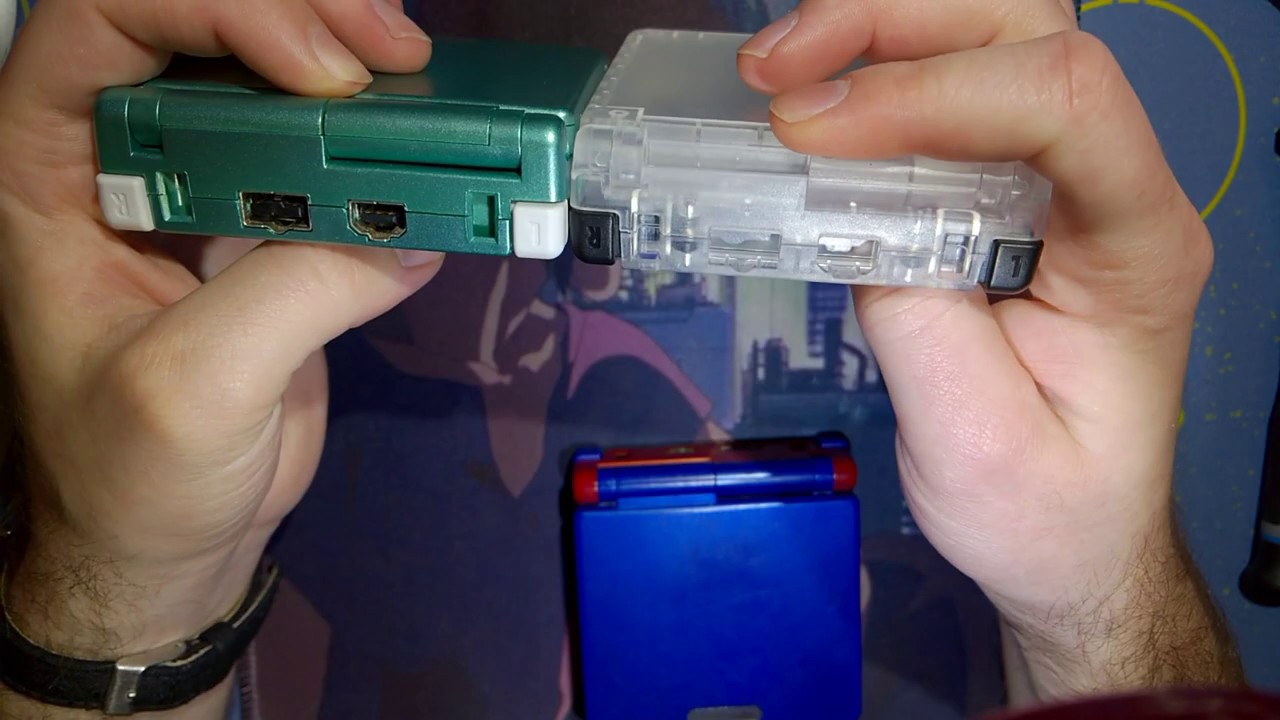
I don't own this Gameboy Light but I saw it on a listing online. The screen seems to have a bad polarising filter, and it looks to me like the backlight is gone right? just a sanity check

The light is hard to tell as it’s not easy to see except in the dark
hmm I see
from some other pictures I've seen of working Gameboy Lights it seemed a lot brighter and had this teal tint to it
Yeah the teal is one signifier. My personal one it’s hard to see even irl tho. With the burnt polarizer it might be obscuring it.
yeah you're right, thanks!
gameboy advance sp
will not stay charged
red light battery low indicator turns on minutes after charging for hours
Checked battery, is slightly bulging in the middle. should i replace? if so, would it hurt to keep the current battery so i can keep playing it, or would that be dangerous
Game Boy Resource
The place for information and tools for Nintendo's Game Boy handhelds.
But bulging batteries should also be replaced
ah thank you
Having kind of an odd issue with AGB triggers after installing the laminated IPS kit. They're black clicky triggers I swapped 2 years ago. You hear the audible click, it seems like they press, but they dont really register in game. I have to push hard and that's still finnicky. However, the OSD menu works consistently with normal pressure. Triggers seem to work fine with the OSD...
Finally fixed my slate shoulder button fitment issues... I ended up switching the back shell to a good condition OEM shell (since these things are designed for OEM, i figured the aftermarket shell was the problem), and now the shoulder button actuates without any problems
my only regret is now I've gotta try to get the slate sticker off of the aftermarket shell with a hair dryer and razor or something lol
I gotta stop throwing stickers on these builds before I'm 100% satisfied with em
can you post some photos of the install? sounds like you have a pinched wire
Ignore the dehum board. One of my early builds before I knew better.

do some troubleshooting. remove the control wires and see if the problem persists. the left wire does look a little pinched but that might be lighting or weird sharpening
TY. I don't have great luck with triggers for some reason. They will often act funky after I work on a board and I don't even touch them.
Try to keep flux and IPA away from them.
can you show the other side. there are caps and resistors that help with de-bounce that may have gotten damaged
R44/C64 R43/C64
I could but I'd have to do it later. It's been dressed up already. All I did with this was take it out of a retrosix build and move it to an FP build. The only work I really did was on the wires.
Was working well before that.
Do you think it's possible that the buttons on the triggers are too short for the triggers?
They do work but I gotta reaaaally press down on them
Alright so I took the the triggers off so I could press the physical button and they work fine like that. I think FP made a bad batch of buttons. I ordered 2 sets and one of the triggers in one set was literally missing half the button.
i cannot see the length of the nub in your photo
but the button nubs need to match oem to trigger correctly
the typical blue tacts that are used will need to be filed down for example
LOL I'm sitting on RM's page about to order those
I wish FP would let us buy the ones they made
they arent made. they are NOS switches
Check this out. This button came like in this bag

Whole end of it is missing
I'm gonna try with some confirmed good trigger buttons and report back
we have the same blue tact listed in our parts list if youre unable to buy from RM
otherwise NATALIETHENERD for a discount
Thanks Mike, you're always super helpful.
Uhh.... it was the trigger buttons. The other set I have from FP weren't working right either.
...the old ones from R6 are fine...
Put the display PCB in the new shell. Should I be concerned about the slight flex/bending here?

Sorry about the crummy photo; I took this on my iPad as my phone is having issues rn
So far I haven't run into any major issues
I'd open it up and see why it's not aligned
I made sure to check that the bracket was put all the way down into the shell
I honestly can’t be bothered to take it apart and check again
sorry if I'm interrupting, but do you guys know if a dirty power switch might make a GBL backlight not turn on?
it turned on a couple of times but now I can't get it to turn on again, maybe it gave its last breath idk
the power switch is definitely dirty as it didn't turn on at first before I soaked it with IPA (I was just testing it out, I'll clean it properly afterwards)
partially yes. but it is also possible the transformer circuit for the backlight is getting power but not working
it is a bit of a common problem that some component of the high voltage side fails
or a broken trace on that circuit as it is susceptible to batter corrosion. schematics pinned in #troubleshooting-archived
The shield for the light isn't soldered down to anything so just get under the side tabs and it should come off easily.
oh nice
I think it's because I'm probably using a RIPS V4 bracket in a Funnyplaying Q5 shell
I’m assuming that the leads from the EL panel are making a connection? I don’t have a light anymore but IIRC the leads are pressure mounted

ok that is actually a crippling mistake. there are no aftermarket switches

found it
😓
I think it's the same as GBP yes
yeah mine's like this

the power switch isn't really that dirty as well

is the solder on those pins a common thing on these older Gameboys?
seems like there's too little solder
I assume the display screen for the RIPS V4 kit is easily replaceable but the main board is another story
i dont believe the button board is sold separately
its very likely the mismatched brackets as the funnyplaying shell isnt designed for OEM screens while the v4 bracket is designed for OEM shells
Hm
Wondering how much I need to trim the bracket by
I'm just wondering for those who have the RIPS v4 and Q5 displays could measure their brackets to see their differences in thickness
mike did some science and they're not the same. So don't lose the GBL switch/wiper
the backlight still doesn't turn on sadly
but one of the prongs seems a bit twisted
the one that sits there, maybe it's unrelated cause that one is for the off position right

still required to drain the capacitors
so try to be delicate and bend it back to position
there's a tone on the speaker as well when I turn it on, it gets louder when the power switch is in the light position
maybe capacitors?
do you have a multimeter?
no, probably better to continue this after I get one right
I was already planning on getting one
the next steps for diagnosing the no light is only with a multimeter
making sure you have voltage from the contacts, making sure the transfomer is producing voltage
it is high voltage. ~70V so the risk of shock is real hence the big logo on the board
I see, then I'll get the multimeter, thanks for the help!
Tried whittling down the corners of the bracket (where the holes go), still seeing a bit of flex on the main board

make sure the front board isnt getting pressure from the bracket itself
looks like the clearances are different
Would a Q5 bracket be easier to fit with the RIPS v4 display? I assume I could heat the tape with a hair dryer and carefully pull everything out
can you post a photo of your bracket?
im now confused what you have
this is supposed to be the V4 bracket
The one I have looks similar (if not exactly) to the one in this video
https://www.youtube.com/watch?v=FMIJTbPebJ4&t=454s


BIGGEST Backlight IPS Kit for the Gameboy DMG! RIPS V4 OSD IPS Kit
In this episode of my random repairs series i attempt to mod an original gameboy by adding a RIPS V4 OSD IPS screen. This is the next revision of the RIPS IPS screen where the previous version was the RIPS V3 IPS Kit, so what is new with the OSD V4 version you ask? Well this kit...
Feels more like rubber than plastic
So you're most likely correct @dry wadi
Wondering if I should purchase the Q5 bracket or trim the RIPS V4 bracket even more
At least when I trimmed the RIPS bracket I was able to turn the contrast wheel more freely
Has anyone tried the RIPS V4 display in the clear "Play It Loud" case? Did you notice any board flexing using the included bracket?
you can ask that in #modding for more visibility
Gotcha
Got my multimeter, do you think it's worth to make a separate post? Maybe you know a video I could follow of what to test on the board with it
Or maybe I should learn to read the schematic first
if you know how to measure continuity and voltage, you can do some quick diagnostics.
voltage on the high voltage pads on the front marked EL next to the BT+ should be about 70V AC

YouTube
do video 5-9 then circle back to video 4
ok 🫡
by on the pads you mean between those 2 right?
the ones where the backlight connects
checked for AC voltage on it, showed 0
your meter has to be in AC mode usually. just confirming
mine has the manual range he spoke about
it's on the 200 option of AC voltage
there's 200 and 600
yes 200 would be the correct range, since youre measuring up to 70V
yeah I figured it's just the closest number to what you want
im sorry if i wasnt clear, the GBL has to be powered on and in the EL-on mode
yes, powered on, in the Light position
the console can sit in the rear shell with the batteries and door on, it wont move unless you knock it

I'm using one of these, should I change to the shell?

the transformer on the front, iirc the schematic has the same numbering as the pins of the transformer

in DC mode, pin 2 should have 5V
meaning pin 6 and 10 are the ones on top, 1 through 5 are left to right pins on the bottom
red on pin 2 black on BT-
do be careful for not to short anything. the leads are bare exposed metal
4.88V
kk thats correct
youve done what you can to at least prove that you are getting power to the transformer. the transformer is not working or not oscillating.
the transformer has no drop in replacement iirc. the self oscillating circuit to make AC voltage is the grouping of stuff on the back side

the next steps would be to confirm that the traces of the PCB are intact, you would measure continuity from one component to the next. green lines means they are connected, lines that cross over each other are only connected if you see the green dot
so if the transformer is gone, there's no saving the backlight?
ie one side of R9 is connected to C34 and pin 2, the other side of both components connect to a leg of Q3
correct. until we find a replacement transformer
unfortunately its a bit of a rare console not a lot of work has been put into finding replacement parts as so. luckily its just a game boy pocket with a backlight
so diagnosing and replacing parts on the pocket portion of it is easy. just the light part has not been worked on
we are extremely blessed already to have schematics
transformers are also particularly difficult to get as sometimes you have to crack them open to count windings
the backlight?
yeah
the first time I tried turning it on with the shell opened it worked
then it stopped working
switch turned all the way on, AC mode on the multimeter, both leads on the EL pads one on the left one on the right, and you got zero volts?
I'll check again just a sec
yep 0
this is how the multimeter is setup

there's a noise on the speaker as well, not sure if it's related, but it gets louder in the Light position, compared to the normal ON position of the power switch
these right?

yes. they connect from the front to the back you measure continuity with no power
measure continuity on the back side to make sure that side is connected, then you can prop it up and measure front to back
GND is ground you can touch BT-
ie one lead on BT1 one lead on pin 2 of Q3
yes
the components themselves, you can only measure R9 in your meters 20k Ohms mode. K meaning kiloohms. R9 is 4700ohms/4.7kohms you need to know your decimal places as the display will change
oh I thought it was just to see if they were connected
you mean to check if the resistance is correct as well?
yes but if you wanted to narrow down exactly what component has failed
oh ok
so there are cases where everything is connected but some resistor is failing right
R = resistor
C = capacitor
Q = usually transistor
its usually a capacitor or transistor
hmm, makes sense
hmm, continuity doesn't seem to be a problem
I'll check the resistances
you would only be able to measure R9
oh yeah right, for a sec I thought you had said multiple components when talking about the resistance
but you mentioned only R9
capacitors are not measured in circuit (installed) transistors like this kinda arent really metered out.
in addition to your meter not able to measure capacitors
I think I left out some combinations
I'll go over them one by one just to be sure
understandable. you would have confirmed the circuit is good and getting supply voltage in this exercise
no wasted effort
I mean might as well right, any slim chance I can find something wrong is better than nothing
transistors are labeled on the schematics with part numbers. the capacitors are labels with their capacitance value, they are 0603 package size if you would like to order parts
do you think reflowing them can help in any way?
wouldnt hurt, if you are touching the solder joint itself while doing the continuity testing it partly confirms the joint is good
true, doesn't make much sense to do it then
if you have the confidence to do it, do it. its a low risk next step now that youve at least confirmed some things
its another item to check off the troubleshooting list
alright then, I'll go on with the testing, thanks a lot for your help Mike, really appreciate it!
this session will cost 3 high fives and 2 good vibes. please pay in exact change /j
jokes aside thank you for following along
troubleshooting aint easy and you did lots of things
it's cool to see how this stuff works
even if I don't manage to revive the backlight I at least learned new things
@fair karma you should be able to post it here
To judge your soldering capabilities, can you post pics of the soldering practice kit you did prior to starting your battery swap?
...I haven't done a practice kit yet.
Mind that repairing the damage you've done is significantly more difficult than simply swapping the battery
For the current situation if you intend on fixing this yourself, I recommend setting it aside until you've gotten more soldering practice on-hand, lest you break it further
If you want this working now I recommend commissioning a repair
this is the test kit I have but haven't work on yet:

It'll look a little ugly regardless of who fixes it 'cause the repair will require a jumper cable, unfortunately
that's fine. as long as it works and saves
Don't discard the battery, as the pad can be used to make it a little more aesthetic
I saw this on reddit as I was researching solutions

Yes, but do you trust yourself to solder to those without accidentally removing that capacitor?
not yet, no. But I want to get to that point
Also, it looks like you've gotten a tiny bit of solder on the cart pins?
If that's just dust, ignore it
If it is solder, also ignore it, as you cannot remove solder from the pins, and trying to do so will just spread it around
that's just dust, I believe
A note about this: soldering to R9 risks removing the component and you'd have to re-solder that
But the bottom one, the via (the hole) is also notoriously difficult to solder to as they're coated to keep solder off of them
Do you have kapton tape?
Or a fiberglass pen?
Your current task list:
- Do the practice kit, post it online to get critiques on how to improve
- Practice soldering jumper wires (also, do you have the appropriate wire?) on the practice kit
- Study how to safely solder on a cart without ruining it (where does the kapton tape go, how do you solder to a via)
OR
- Post an ad in #1049401311101206649 asking someone else to fix it
Personally I would desolder the pad off of the battery and re-adhere it to the board. It won't make it work, but it'll look a little better aesthetically
thank you so much for the task list. Should asking for feedback be posted in modding or another channel?
any particular method to re-adhere it?
I'd say #modding is fine
The price for this advice is me using your image and this comment as a cautionary tale for the future

I will remember it well
I'm definitely one of those people who try to sprint before they can walk and it has bit me in the butt on more than one occasion. I just need to slow down and learn new skills before tackling things like a dumb dumb
Damn, after almost 2 months, funnyplaying ain't answering to my ticket
write a new email. they should be back in full now
do you think I could get some sort of copper wire and make one of those copper prongs?
or is it just not savable at this point
no not rigid enough
I lost only one of the copper prongs, but the other one is also out of the slot and I don't trust myself to put it back in place without losing it
the GBL switch is also not replaceable which doesn't help
no aftermarket equivalent afaik
correct
what was the difference from the GBP switch, iirc you were the one who checked it right?
is it just the size that's different?
the prongs
oh I see
you cannot use the shield from the pocket on the light. the outer metal shield will short the console if you used the pocket one
the outer shield I still have
I just lost one of the prongs that makes the contact
they seemed off to me ever since I saw them
they weren't both bent to the same angle
and that SW1-R10 goes straight to the oscillator circuit
tape and touch every surface
pray that the universe will return the contacts back to you
I looked for them with a flashlight I don't think they're coming back
my room isn't the best place to do this tbh, but it's all I have
easy to lose stuff on the floor
you can try taking the slider from a pocket or color and dropping it in to see if it works for you. i have not been able to replicate, but i only have very bad GBLs
is the power switch shielding on the pocket not soldered as well?
opened mine up now, looks soldered
idk, at this point I've developed a crippling fear of Gameboy power switches
they are fiddly. but they are the source of so much power problems
I'll do this during the day, I think it's slightly better to see all the very small parts that way
but thanks as always man
I'm just sad all these problems keep happening
now I potentially have 2 parts that have problems and are irreplaceable
If you remember this, they haven't answered yet
Not even in a new ticket
Can anyone measure the values of R7 and R16 on this revision of the FP kit?

@fallow jacinth hello

It looks like you’ve got the right idea
at least I think, it’s a little hard to see what’s going on there
but your only goal is to remove the head from the shaft.
The biggest issue really is that I was recommended a certain size bit but my dad just has all his drill bits just sitting around and the hardware store didn't go small enough lol
It’s nothing that needs to be hyper specific
you just need to grind away the head
This just keeps going and going D:

is the bit you’re using actually cutting? Or has it just rounded out
The screw kind of just seems to be rounded out. It's still shaving something off when I do it, its just not making very noticeable progress
Hacker voice I'm in

Thanks for the extended help @fallow jacinth!!
My left and up buttons don’t work are the contacts broken

What are the membranes
The rubber bits that go between the board and the buttons
rubber pads
EZflash Omega keeps freezing, can't play for more than a few minutes without it happening. I'm guessing just lightly wet a q-tip with IPA and clean the cartridge slot and cartridge itself? Anything else I should know or try?
could be batteries as well
check if it happens after swapping out the batteries on your Gameboy
cleaning the contacts on the cart may not work, but it doesn't hurt
weirdly enough just rolling the batteries seems to have fixed it, thanks!
when rolling the batteries "fixes" the problem usually it means you have to clean the battery contacts
if they're too rusty it's pretty cheap and easy to swap them out
IPA on the contacts?
yup