#Novel 5DOF printer design (Helios)
1 messages · Page 1 of 1 (latest)
 grizzled dew
update
 umbral trail
I would try to make the cantilever as rigid as possible and add way more reinforcment to the Z axis base to keep it from bending as much as possible
grizzled dew
yeah i agree that tiny bracket is not gonna do anything
 blissful narwhal
i feel like using a combined extruder+hotend is a lot of weight to be putting on the pivot at the end of cantilever like this. Personally i'd be considering bowden
Either actual bowden with the extruder stationary on the top of the Z-Beam, or a N14-based Microbowden toolhead where the extruder remains stationary and just the hotend + fans tilt
 half lotus
what keeps you from making this into a full-framed bedslinger?
 tardy fox
looks like this https://youtu.be/VEgwnhLHy3g with a 5th bedslinger axis to make it non polar

Thank you to JLCPCB for sponsoring this video! https://jlcpcb.com/?from=joshuabird
JLC3DP 3D Printing $0.3& CNC Service Starts at $1, Get $60 for New Users: https://jlc3dp.com/?from=jb333
Run the open source 4 axis slicer code yourself: https://github.com/jyjblrd/Radial_Non_Planar_Slicer
Github link for the printer: https://github.com/jyjblrd/...
pretty cool
 desert river
dual shaft y motor like that is a fun idea
you should add double shear
but
it’s neat
grizzled dew
half lotus
what keeps you from making this into a full-framed bedslinger?
The extruder must be able to rotate +90 -180 degrees so a bar going across would collide with the print. Has to be supported on one side only
half lotus
nope. still not getting it
grizzled dew
tardy fox
looks like this https://youtu.be/VEgwnhLHy3g with a 5th bedslinger axis to make ...
Yeah i love that design but tried to make mine have bigger accessible nozzle tilt area so hence longer beam
grizzled dew
half lotus
nope. still not getting it
Like imagine prusa but the nozzle can rotate. If it rotates above horizontal then the gantry is gonna be below the nozzle and get in the way
Cut off half the gantry and it works
grizzled dew
blissful narwhal
Either actual bowden with the extruder stationary on the top of the Z-Beam, or a...
I couldn’t find what you are referring to online? Link pls?
grizzled dew
half lotus
or the x gantry?
X gantry
desert river
half lotus
nope. still not getting it
The X beam would hit the print
Because the hotend doesn’t stay perfectly up and down
With this setup the hotend is fixed to the end of the cantilever
So the X beam won’t get in the way
half lotus
ah, so you'd need to drop the hotend down somehow so it could be able to point upward
anyway, you might want to consider cpap or shop air to reduce weight as opposed to a fan
desert river
half lotus
ah, so you'd need to drop the hotend down somehow so it could be able to point u...
well yeah but that’s not what I’m saying
 grizzled dew
half lotus
anyway, you might want to consider cpap or shop air to reduce weight as opposed ...
I was thinking this but the fan is like +50g max
desert river
here
half lotus
I wasn't really considering printing downward yeah
half lotus
grizzled dew
I was thinking this but the fan is like +50g max
at the end of a cantilever, and on your image, also at the end of a second cantilever perpendicular to the first
desert river
grizzled dew
I was thinking this but the fan is like +50g max
you need to minimize weight as much as possible or you will have issues
half lotus
lightweight hotend, lightweight extruder, whatever the meta is now
desert river
ideally if possible you should have dual vertical towers and have the horizontal axis between the two
top down

blue is R red are the uprights
umbral trail
grizzled dew
I was thinking this but the fan is like +50g max
I would not use that heavy ass biqu thing at all to be honest. Put the extruder on top of the Z extrusion and feed the filament to the hotend with a bowden tube. That way you don't have to worry as much about weight on the end of the cantilever
 vocal walrus
Your Y stepper mount will bend causing the belt to wear down quickly. For Z you'd want to have 2 carriages on a single rail instead of 2 rails. Your Y assembly could benefit from an extra carriage as well to resist the nod.
grizzled dew
Novel 5DOF printer design (Helios)
helios is a chatgpt name and its perfect in every way myth lore wise
 livid sequoia
very cool
grizzled dew
CAD done
my school is letting me do independent block for this but theyre debating on money
tardy fox
independent block?
half lotus
Does it need to be that long?
umbral trail
adding a balanced counterweight would probably be more space efficient but I guess model for the render just uses a standard extrusion lenght
adding a "counterplate" to the wheels and the pulleys could easily increase the stability of the arm without much work I imagine

Here
vocal walrus
umbral trail
adding a balanced counterweight would probably be more space efficient but I gue...
But counterweight can't be balanced here unless you add another sliding assembly
umbral trail
True, didn't think about that
grizzled dew
Shenanigans during assembly
 ionic thorn
Post the portal turrets song ❤️
half lotus
how does it determine if moving the bed side to side is better than doing normal polar bed stuff?
or visa versa. you could treat it as a standard cantilever bedslinger, except sometimes it might be optimal to rotate the bed, but when?
desert river
half lotus
how does it determine if moving the bed side to side is better than doing normal...
Because it’s not being treated as polar
It’s being treated as an additional rotary axis
It’s not replacing anything it’s adding on
To answer how you determine what’s best
Frankly there isn’t automatic slicing past 3 axis
So you manually tell it to do what you want
ionic thorn
desert river
Frankly there isn’t automatic slicing past 3 axis
There are some developed algorithms for 4 axis slicing that utilize deforming a 3 axis slice of the object to remove any overhangs. Not sure how you’d go past that though
This video explains it pretty well
Thank you to JLCPCB for sponsoring this video! https://jlcpcb.com/?from=joshuabird
JLC3DP 3D Printing $0.3& CNC Service Starts at $1, Get $60 for New Users: https://jlc3dp.com/?from=jb333
Run the open source 4 axis slicer code yourself: https://github.com/jyjblrd/Radial_Non_Planar_Slicer
Github link for the printer: https://github.com/jyjblrd/...
So technically not a slicer but an external program that uses g-code from a 3-axis slice and optimizes it so everything can be printed without supports
desert river
ionic thorn
So technically not a slicer but an external program that uses g-code from a 3-ax...
Oh i thought it was still fairly manual
ionic thorn
Nah, unless you consider dragging and dropping from one program to another to be manual 
Effectively it’s no different from normal 3-axis nonplanar, but the 4th axis makes it so the nozzle is always held perpendicular for the best line adhesion
half lotus
but what do you do with an extra axis?
grizzled dew
half lotus
how does it determine if moving the bed side to side is better than doing normal...
Theres only 1 solution to any input of 5 position variables xyzcb
But yeah if the point is too close to the center of the bed it could sweep out a massive angle for a small translational change
Speed isnt an issue though
grizzled dew
ionic thorn
Effectively it’s no different from normal 3-axis nonplanar, but the 4th axis mak...
That video is nice but i wonder if it can be generalized to 5 axis
Because his printer basically MUST point extruder towards center of bed while it can change elevation angle
grizzled dew
half lotus
but what do you do with an extra axis?
Adding fifth axis makes it so you can place the nozzle anywhere and angle it in any direction
4 axis gives you full translational freedom but you only can spin in a single angle
ionic thorn
grizzled dew
4 axis gives you full translational freedom but you only can spin in a single an...
Yeah it is really something where you have to combat the conceptual “how and why”
Cause yes a 5th axis gives extra freedoms, but also WHAT extra freedoms is difficult to figure out
And how to actually use them properly to do something that can’t be done with something less complicated
half lotus
it is easier to conceptualize when all degrees of freedom are on one object
and makes it more obvious that a 6th degree of freedom is unnecessary when the nozzle is radially symmetrical and homogenous... or however you call something that doesn't change if you rotate it.
I dunno. I studied biology.
grizzled dew
ionic thorn
Very fancy belt knot but damn that’s impressive
 uneven flower
Looking forward to see the first print 
grizzled dew
thanks!
grizzled dew
ionic thorn
Very fancy belt knot <:vaulthah:597787241812852736> but damn that’s impressive
1220mm gt2 belt coming from china rn lol
half lotus
I think it's gonna be a biqu toolhead. relatively cheap and compact option as direct extruder designs go.
I think most designs won't work great, since they have fans to the sides, which in this configuration would potentially be rotated into the print at extreme angles. Seems it’s actually pretty good for purpose.
 ocean mirage
Looks really cool, impressive progress so far!
grizzled dew
half lotus
I think most designs won't work great, since they have fans to the sides, which ...
yeah that exactly
grizzled dew
desert river
where’s the toolhead 👀
school didnt want me to have "fire hazard" in my room 😔
so its a fake extruder
ionic thorn
Any concern about torque forces or do you expect the Y axis to not move very fast
Cause my worry with a toolhead that big hinging on a single point is the amount of wobble that could be caused by torque
half lotus
ionic thorn
Cause my worry with a toolhead that big hinging on a single point is the amount ...
oh uh, you know, it might even create a non-negligible twist in the y gantry (he labeled the extendy arm the y. dunno if that's normal for polar designs).
ionic thorn
the extending arm is the y axis and the toolhead spins on a separate rotational axis
So my thought was when the arm goes in and out for the Y axis it would create torque
half lotus
torque with what as the center?
 half lotus
the arm going in and out isn't going to make much torque there
but it may change the amount of twist in the gantry member
...we might be talking about the same thing
ionic thorn
Torque as in the rotational force created by an object at the end of a motion arm
The arm going in and out creates torque on the extended toolhead
Due to it sticking out away from the point where it connects
Meaning that back and forth motion on the Y axis will cause the toolhead to create a torque force
It's the same as how a toolhead on a CoreXY can cause torque if it isn't balanced since the back and forth motion on a Y axis can twist the gantry
half lotus
ionic thorn
It's the same as how a toolhead on a CoreXY can cause torque if it isn't balance...
you can't do anything about there being a point mass at the end of the lever that's moving in and out. You'd need a reciprocal arm that would be useless weight and added complexity. You can mitigate the downward bend by stiffening it, which I guess you could do by using a HFSF5-2020, or if the pulleys at the ends are bigger than 20mm in diameter so the belts won't rub, you might be able to use a HFSC5-2020. I was concerned with it being off to one side, which would introduce a clockwise twist on top of the end drooping downward.
ionic thorn
half lotus
you can't do anything about there being a point mass at the end of the lever tha...
My only comment was that it's a heavy extruder
I know perfectly well you can't not have it there
I was just saying going with such a big toolhead was more likely to be an issue
half lotus
I think he went with it because it's cheap for an all-in-one toolhead as well as slim on the sides.
what is the meta for a light toolhead here, assuming you have to go with a direct drive?
vocal walrus
half lotus
what *is* the meta for a light toolhead here, assuming you have to go with a dir...
I assume you mean direct extruder and not direct drive
But well, remote cooling for both the hotend and the parts cooling would be a step in the right direction, there were some lightweight hotends over the years as well
half lotus
vocal walrus
I assume you mean direct extruder and not direct drive
But well, remote cooling ...
Yes, a direct drive extruder. A 3010 isn’t a lot of weight to add. The extruder stepper is the heaviest thing that could be moved off of the cantilever easily. A couple of small fans is small change.
vocal walrus
half lotus
Yes, a direct drive extruder. A 3010 isn’t a lot of weight to add. The extruder ...
Direct drive extruder like the one on stock Ender 3?
Remember that weight isn't everything here either
half lotus
Direct drive extruder as opposed to a bowden extruder.
vocal walrus
half lotus
Direct drive extruder as opposed to a bowden extruder.
Ender 3 had a direct drive bowden extruder
Prusa Mk4 has a geared direct extruder
These are 2 different things and can coexist
half lotus
vocal walrus
Ender 3 had a direct drive bowden extruder
Prusa Mk4 has a geared direct extrud...
You know what? I think this is another “cartesian” thing.
umbral trail
Direct drive extruder: The motor directly drives the filament, no extra gearing etc. See Ender 3 extruder
Direct Extruder: Extruder sits on top of the hotend
desert river
umbral trail
Direct drive extruder: The motor directly drives the filament, no extra gearing ...
a direct direct drive extruder directly directs directly directed filament in the right direction
grizzled dew
ionic thorn
Any concern about torque forces or do you expect the Y axis to not move very fas...
the h2 extruder is like 200g total with fan and ducts and its obviously not built for speed
also at this point stuff like slight bending is a second order concern behind actually making it print
umbral trail
I mean you could probably quarter that by using a hotend with a short bowden extruder but yeah, actually printing should be a higher priority
ionic thorn
grizzled dew
also at this point stuff like slight bending is a second order concern behind ac...
I’m not saying it won’t work. And I know the goal is to just make it print. I guess I’m just looking at things on an accuracy and longevity standpoint. I’m simply looking at how it has the potential to make the Y axis a diagonal line simply because of how cantilevers work, and then the additional cantilever of the toolhead. I don’t at all think it wouldn’t work, and this is an incredible project, I’m just applying my own perspective. And yeah the H2D toolhead is massive but it also isn’t being hung from a cantilever on a cantilever
I’m trying to provide talking points or ideas because I do want to see this project succeed.
It might be beneficial in the long run to maybe design in a lighter extruder and cooling system, potentially via a Bowden and CPAP setup, but for the time being it definitely will print
grizzled dew
i think having a double gantry would be the next step. it would get rid of that second cantilever you're talking about
might cause more collision issues though
ionic thorn
That’s actually something that the addition of another axis can help with because you can keep the printer from running into the object on the bed even if you don’t have it as a cantilever
But I don’t have a possible clue how you’d implement that into the motion algorithms
Normally on a polar printer you can’t have a normal gantry and HAVE to make it a cantilever because of collision
But having an X and C axis makes it possible
BUT it would entirely change how the printer functions on a fundamental level and wouldn’t work with how your motion system works right now
The toolhead would have to be able to rotate a full 360 degrees
Or I’m just spouting nonsense bullshit I’m still figuring it out in my head but it wouldn’t be worth the sheer amount of complication it would add
Cantilever is just way easier to implement
ocean mirage
What do you use for slicing?
half lotus
A better question is if he’s using an existing slicer as a base or is doing it all from scratch
grizzled dew
ocean mirage
What do you use for slicing?
using orca for getting toolpaths
but then those are deformed and the angle of approach for extruder is calculated
grizzled dew
half lotus
A better question is if he’s using an existing slicer as a base or is doing it a...
yeah no way im making a slicer
grizzled dew
overhang correction rotation and diffused corrections
umbral trail
grizzled dew
overhang correction rotation and diffused corrections
Just tell a company about your project and ask if they would like to sponsor you
desert river
wait, are you running with only the pulley hubs on the shaft?
 half lotus
bro needs to get smooth idlers
grizzled dew
desert river
wait, are you running with only the pulley hubs on the shaft?
Wdym
grizzled dew
half lotus
bro needs to get smooth idlers
Lmao i would have had to buy another item
But had a bunch of the toothed idlers lying around
Can’t imagine it would be fatal
desert river
grizzled dew
Wdym
the hub of the pulley is where the setscrews are
does the motor shaft not extend through the whole pulley
desert river

grizzled dew
Would have had to got long shaft nema or make mounting plate thinner
desert river
that’s not good for your motor shafts and significantly reduces possible belt tension
grizzled dew
Oh i bet
desert river
grizzled dew
Would have had to got long shaft nema or make mounting plate thinner
long shaft motors are not very expensive
half lotus
grizzled dew
Lmao i would have had to buy another item
https://www.amazon.com/RLECS-12x8-5mm-Aluminium-Suitable-Machines/dp/B0D7CCF9ZW/ literally less than $6 and it's a straight upgrade on prospective print quality.
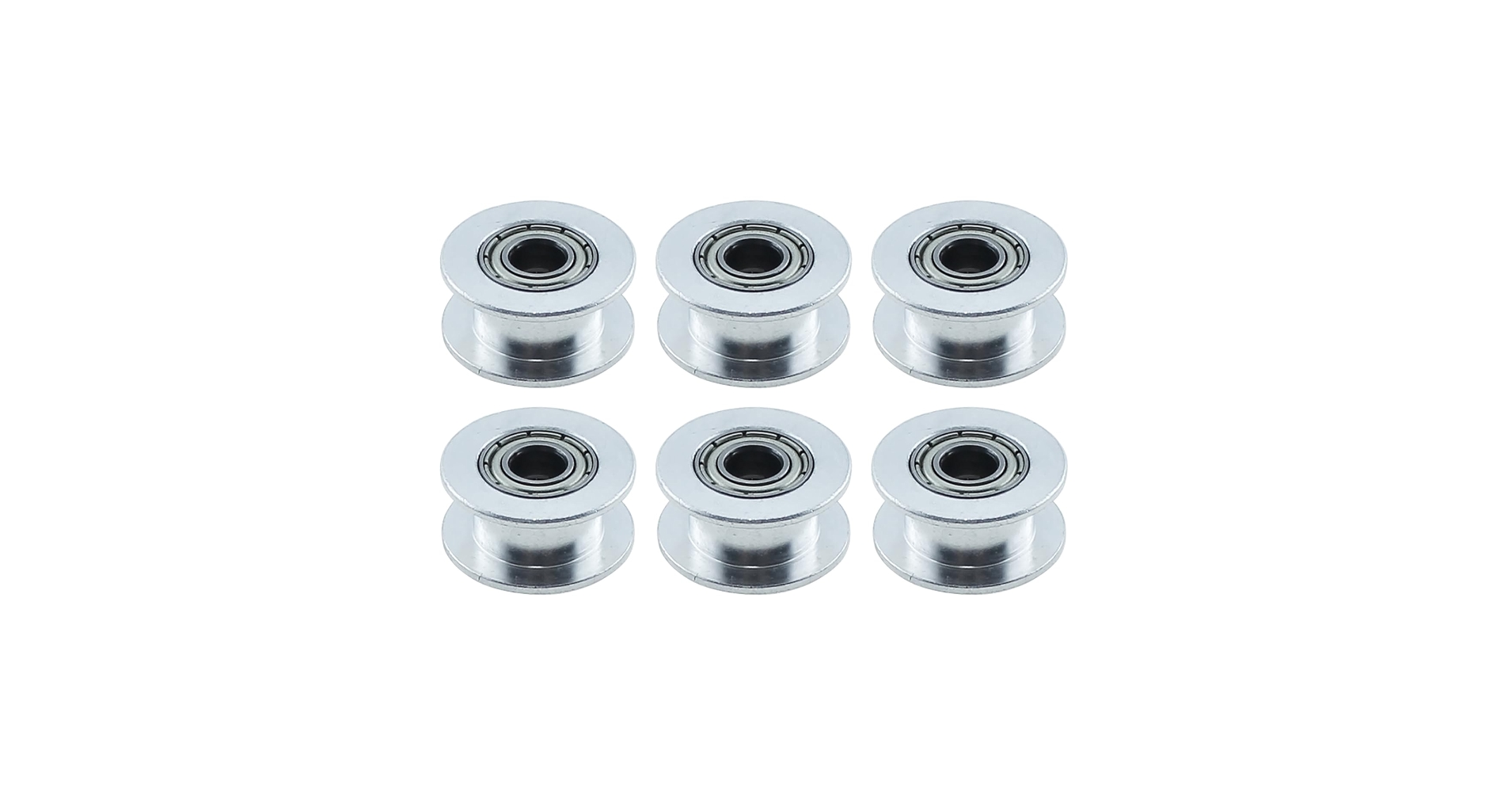
Name: GT2 synchronous belt pulley, toothless synchronous belt idler pulley.
Material: aluminium alloy.
Colour: silver.
Surface treatment: oxidation treatment.
Specification: 20 toothless hole 5mm width 6mm.
Application: suitable for 3D printer, CNC, milling machine, gear forming machine, dri...
grizzled dew
Yall are so accustomed to speed optimization and surface quality lol
Its a 5 axis printer the best thing i can do rn it make it work
desert river
grizzled dew
Yall are so accustomed to speed optimization and surface quality lol
It’s not just about optimization and surface quality
It’s about proper design practices and manufacturer specifications (and like, caring about doing it right)
It’s not really even more work to do it proper
grizzled dew
desert river
It’s not just about optimization and surface quality
It’s about proper design p...
Can I see your machine working?
livid sequoia

grizzled dew
Pls don’t nitpick the smallest things on my printer and say I don’t care about doing it right
I built this from scratch in 35 days
livid sequoia
its just so easy to replace them and get better print quality, not destroy your belts, and be able to run spec tension
grizzled dew
Thanks but realize print quality is like 10th on my priority list
livid sequoia
if it was something like completely redesigning part of it, id understand, but this is literally replacing four idlers
livid sequoia
its so easy
grizzled dew
I know
Dude i had to cut bom in half because of denied funding so everything counts
I happened to have them lying around and didn’t want to wait another day and all that packaging waste
Sure you’d do the same
livid sequoia
smooth idlers are literally a dollar on aliexpress
maybe as a temporary solution but id fix it
grizzled dew
If you’re thinking about “print quality” at the conception stage you’d never get anything done
I don’t know why we’re arguing about it
livid sequoia
also belt health and spec tensions
grizzled dew
“Its easy” sure but its its even easier to use what i have
livid sequoia
gonna cost you more in belts than the price of two smooth idlers
grizzled dew
Id appreciate critique on my algorithm more this
livid sequoia
i do printer design not slicer design
grizzled dew
If you could find something wrong with the collision penalized arap optimizer that would be more helpful
Yeah i can tell
livid sequoia
ima stay with the stuff i know
grizzled dew
I’m sure i could go to your machine and find 10 things wrong
livid sequoia
my machine is meh and i know it
grizzled dew
Dude if the belt ever breaks ill let you know
This is like worrying about aerodynamics befote you build a car prototype
livid sequoia
i consider both in my designs
grizzled dew
Show me a printer you designed operating then
vocal walrus
livid sequoia
currently working on unfucking klipper for my polar
Should've used RRF
livid sequoia
vocal walrus
Should've used RRF
thats the new plan
desert river
grizzled dew
Can I see your machine working?
Show me this printer printing.
I’m done interacting with you. Good luck with the build.
livid sequoia
i think it’s time to consider print quality 
 umbral trail
Its a start
 unreal zealot
So there is a 5% chance it works!