#diy heater block, Toolhead build
1 messages · Page 1 of 1 (latest)
 undone wadiBOT
 surreal blade
Mounting.

Still iterating and playing around with ideas for the toolhead. These pics are of some older ideas. Probably wont end up making a ufo style duct. This one was this vortex idea I had. The air would come in the side tangentially spinning on the inside until it's forced out. Kind of like a reverse blower or turbo etc.


Bespoke heater block, future toolhead at some point
surreal blade
I swear lol 🤤, should know this by now, but it's usually best to have whatever parts in hand to measure yourself. Got the 80w heaters and of course the dimensions aren't the same as what's in the diagrams! At least I have few 80w heaters I can use for the next design. Less watts it is, oh well lol
 next forge
surreal blade
I swear lol 🤤, should know this by now, but it's usually best to have whatever ...
Probably still enough for the lenght of the meltzone
surreal blade
For sure, I think it will be fine as well. It's an upgrade to what I've been using that's for sure. Printer all this is going on is my ender based everyday printer that I've had for years
surreal blade
Alright!! Done with the dang Vortex spinny air idea. I give up 😂😭😂😭


 surreal blade
Another iteration.... My previous iterations goals were to be as lightweight as I can get it without sacrificing any rigidity and having each part tie in from two different points. For example, the extruder is fixed to the plate behind it and also down squeezing the two halves of the body together. This also acts as a mounting point for ducting potentially. Those two body's are also each fixed to the plate using 8mm internal square nuts. Also want to use the silicone tubing for the heatsink cooling. I've found with my current setup it doesn't take much to prevent heat creep when the air is remote and directed directly at the base of the heatsink. No fans on the toolhead and doing the klicky probe for less weight. Starting another design tomorrow using some of the ideas I've come up with woo
 next forge
Interesting approach with the remotely cooled heatsink
What system feeds the heatsink cooling? Airpump or fan?
surreal blade
The one I use now uses a dual sequential 5015 fan but its 12mm id tube and this is 7mm. Still thinking about ideas. One I just thought of now is to just tie it in with my cpap blower before the valve I'm going to use. The way it would work is I plan on using a dual valve system that can open/close rapidly that supplies the air to the part cooling ducts instead of waiting on the fans to change speed. The air supply behind the dual valves is pretty much on full. I'll just run it from there I think. Might even need to restrict it
surreal blade
I should elaborate a little better if I'm sharing. Test was averaged over 3 runs, done using a fysetc CNC Sherpa mini at 200c using 0.4 generic brass nozzle and Duramic3D PLA+
 surreal blade
Lots of concepts. Nothing vibes super well yet. Always seem to have a tough time with ideas when it comes to toolheads. It's starting to take shape.

 next forge
surreal blade
Lots of concepts. Nothing vibes super well yet. Always seem to have a tough time...
Do you even save that much weight compared to a 2510 fan?
For heatsink cooling
surreal blade
I'll have to do some comparisons. My goal is for the arrangement to be less weight and less wires. The silicone tube I think is heavier than the wires. My hope is with minimalism and some tweaks it will all add up and be worth it
next forge
I mean the rule of cool still applies here and remote heatsink cooling is right up there on the coolness factor

 teal jacinth
Compare cooling powers both of these can give you optimally
surreal blade
teal jacinth
Compare cooling powers both of these can give you optimally
How would yourself go about that? I have some Thermocouples I could use
teal jacinth
surreal blade
How would yourself go about that? I have some Thermocouples I could use
Just compare pressure and airflow. From pressure and airflow you get a mass flow rate of the air. That's basically the only parameter you need
surreal blade
teal jacinth
Just compare pressure and airflow. From pressure and airflow you get a mass flow...
Ah makes sense, Thanks!
surreal blade
Digging the belt tensioner block. Seems like it would be pretty solid


 surreal blade
Designed heater block, Toolhead, Silicone sockssss
surreal blade
working on the belt tensioner. Trying to make sure everything is tied into each other well. I want all the parts to complement each other for strength and become as one as its put together as much as possible


 surreal blade
Designing ducts  First time implementing CFD. I have yet to learn all that.. Seems like a rabbit hole. Going for it though! Giving SimFlow a try. Doesn't seem like it should take long to get started with. I hope
next forge
"6h of calculations later"
surreal blade
haha I hope its not to much! Going to give it a good try for a day or two
surreal blade

 surreal blade
Cleaned up a few things with the hose mounting, Going ahead and doing the ufo thing. Told my self I was done with those ufos😅 I feel like I'm getting closer to something that will work ok. Not so much worried about looks with this thing. Many of the design choices are performance based. Not close to anything final yet. I might thicken the cpap tube mount a little. The thought behind the current donut is cooling all around the nozzle and the shape is for directing air from supplemental cooling down to the part effectively through the lower slant and taking advantage of the coanda effect over the top radius.


This is all just imagination at this point. Will be interesting to see what cfd shows.


 terse cargo
surreal blade
did you take inspiration from the ufo-n-ator?
next forge
surreal blade
I personally would try to add the cutout in the duct to the front so to have better visibility to nozzle. (Unless you plan on running this on the "back" of the x gantry extrusion you heathen ).
surreal blade
terse cargo
did you take inspiration from the ufo-n-ator?
It totally inspired my last ducting attempt. I saw it a few weeks ago and it popped in my head as something to try. Also some inspiration has come from PIRACER VELOCIRAPTOR's yt channel.
terse cargo
surreal blade
It totally inspired my last ducting attempt. I saw it a few weeks ago and it pop...
yeah that's the same guy
rocksalt on discord
surreal blade
next forge
I personally would try to add the cutout in the duct to the front so to have bet...
I'm with you on that. I even thought about adding a little mirror hehe. It's one of those things about cartesian printers that I don't like. I feel like designing a toolhead would be easier on a corexy with the cpap setup because its easier to get behind the tool head. At least in my brain it seems that way. I might end up trying the heathen way and just try to figure something out lol
surreal blade
terse cargo
rocksalt on discord
Nice! I enjoy his vids
surreal blade
I'm a mess!
 next forge
This is fine
surreal blade
next forge
This is fine<:vaulthah:597787241812852736>
I've come to terms with it. I can get it clean but then back to this one minute later 😂
next forge
Yeah same
surreal blade
Finally got my m1.6 tap and titanium screws in the mail! Then I screwed up drilling the heatsink! Yay me! I was drilling the last hole and the drill bit started to curve inward while in a jig didn't notice till it was to late. Got 5 heatsinks coming today I got for $10. I just need to take my time this time.
 undone wadiBOT
Marlin Firmware
The M0 and M1 commands pause after the last movement and wait for the user to continue. M1 is a deprecated alias for M0.
surreal blade
Well that's done.

Learned some things. If I had to do it again I would have made the block larger/longer, 2mm screws instead of 1.6 and done away with the mze all together
I like the idea of putting the ti screws as far out to the edge as possible and reducing heat travel to the center of the heatsink. The step at the heatbreak junction I'm hopeful it will reduce the flux going into the heatbreak a little bit. I've tried for a week trying to get Fusion360s thermal simulation going but just keeps failing. even after simplifying every little thing like threads and fillets. Drivin me crazy lol🤣!
This old thing is getting a huge refresh! old toolhead design I did sucks. Major source of artifacts. Ducting is hangin on for dear life lol
surreal blade
cpap and cartesians meh... Cant go with the design where it blocks the view in the front. tube behind the stepper? to the side? top? Still havent come up with a design I like.

Designed heater block, Toolhead
surreal blade
 surreal blade
Think I will give this a go. I'd imagine it should work, need to do some cfd testing and optimizing at some point.


 teal jacinth
surreal blade
That's a very sharp bend through a narrow channel here
surreal blade
It's not ideal for sure. Internally its has more curves than it looks like from the outside. That 90° bend is larger and opens up relative to the size of the inlet feeding each side. Even though there is a bend I'm hoping it will have less of an impact than just two equally sized internal diameters doing a sharp 90° turn. It all kinda opens up and gets less restrictive until it gets near the nozzle. I really need to get a cfd program figured out so it's not just guessing. Always seems to me things aren't always like they seem when it comes to that stuff. I thought about having the cpap tube a little higher over the extruder more without any sharp bends at all. Might play with that idea more. Definitely would be a better flow path than it is currently.
surreal blade
happy bend

 surreal blade
 surreal blade
Going to make all this flow better. Any thoughts?

This is all in early concept stages still.
I think it looks weird but meh, not really worried about that as much. More worried about making it as light and stiff as possible.
When I made this block I thought having the choice of the mze on and off would add to its versatility. If the printer im throwing it on runs 300-400mm/s would the mze be mandatory? I feel like I should have just designed a longer block mabie lol
next forge
surreal blade
When I made this block I thought having the choice of the mze on and off would a...
Hard to say if you need the mze. You need to test for max volumetric flow
undone wadiBOT
Volumetric Flow
Volumetric flow rate is the way we measure the amount of material that our hotends can melt per second.
Typically we use the unit mm³/s or "cubic millimeters per second".
Pictured below are some typical values of the max achievable volumetric flow rates on commonly used hotends. These values are given as a range because they depend on a variety of other factors such as type of material, extrusion temp, nozzle size and geometry. In practice, achievable volume may differ from these marketing values.
To understand why these values are important and to make use of them you should understand the simplified formula for calculating the volumetric flow rate:
line width [mm] • layer height [mm] • speed [mm/s] = volume [mm³/s]
Further reading: ?morevolume

?volume requested by: m.von.d#0
surreal blade
 Thank you! 😁
Trying to make something kinda like the Rapido.
I dove kinda head first into this project.
next forge
Rapido at home and such
 solid onyx
surreal blade
Going to make all this flow better. Any thoughts?
If you are using software that shows the COM, you should place that entry to better suit the COM location. You will lose some energy the way you have it, those two 90° turns are not ideal. The COM looks like the hose is better suited in front of the motor. The CPAP hose should be bigger, 19mm, and have some space to split. If no space, make a bigger area above the split.
Another thing to watch out for is the exit velocity. No matter what you need to establish the correct speed out the exit. If the exit orifices volume is too high the duct will not perform at lower speeds. So you have to determine how much fan is needed and adjust accordingly. I like to get the exit speed high enough that I can hear it shear off the model being printed, or at least know that I can. The problem can be that if the velocity is too high at lower speed, ABS will be overcooled. So there is a balance to tune the exit volume to suit your build configuration.
surreal blade
Cool! Thank you for your advise 😁
surreal blade
solid onyx
If you are using software that shows the COM, you should place that entry to be...
Going to make another with those concepts in mind
surreal blade
solid onyx
If you are using software that shows the COM, you should place that entry to be...
Have you seen the cpap part cooler set up with the flap valve? Was thinking of building that once I start on the cpap motor side of things https://youtu.be/aj2Hj1Aei24?si=sCXu0In79iIrEAYB

Controlling the airflow with a flap allows for more precise cooling of overhangs. This enables the printing of more durable parts, as there is no overcooling caused by the prestart of the blower fan. Overcooling is also eliminated due to the lack of impact from the rotor’s inertia.
The WS7040 fan begins rotating at 18-21% power, which may be exc...
Almost finished with this design. has the 17mm hose on there. I do have one of those black 19mm ones. will give that a try


 surreal blade
Rough COM estimate.
 solid onyx
surreal blade
Have you seen the cpap part cooler set up with the flap valve? Was thinking of b...
I don't want to run my pump constantly. But I might make one anyway just to see if I can make some use of it. If your pump is a long way from the toolhead it might be a good idea, but it's gonna be annoying hearing that pump all the time.
surreal blade
It would totally be annoying🤔. Building a printer cabnet next to my computer space, just dont have anywhere else. Kinda sucks, but happy about the cabnet and ventalation finally

 surreal blade
Should be pretty easy to swap out different duct designs

 next forge
surreal blade
Should be pretty easy to swap out different duct designs

I see a tiny interference here
 surreal blade

 surreal blade
To tired to think anymore today .
 surreal blade

Thoughts? Tube is 8mm 0.4 wall arrow shaft. Seems like it would be pretty light I think
next forge
You'll run a toolhead board or just run the wires along the tubes?
surreal blade
I still need to work out a klicky bed probe, adxl mount and a small led light. I think I will do a toolhead board. Wasnt going to at first. Other than a little weight is there any other downsides?
next forge
another point of failure in my opinion🤷
surreal blade
next forge
another point of failure in my opinion🤷
I'm in the same boat. I was thinking of doing something, just haven't figured it out yet
next forge
I would add a piece to fasten the wires to for strain relief
surreal blade
Great idea, definitely will need it!
I was thinking of mabie making a wiring harness connection point
next forge
Good idea
terse cargo
next forge
I see a tiny interference here<:vaulthah:597787241812852736>
who uses a spring anyway? jsut put a screw in there ant it is good
solid onyx
The duct is much better now. The final will be to see how much velocity it makes/plot a curve and determine if the duct exits are the correct angle. Not sure how you have the volume configured for the last 50mm of ducting before the exit, typically I like to make a wedge/larger volume to smaller. Looks similar to one I made for a 2.4
surreal blade
solid onyx
The duct is much better now. The final will be to see how much velocity it makes...
I'm happy with it. I feel like it's something I can start learning some cfd with and then go from there. I just kinda made mental notes and checked the circumference as I went. Learning T-splines in fusion360 is something I need to learn more of. I tried to give it a nice smooth reduction in volume.

 solid onyx
Ducting is interesting to me and I have tried a few different designs. What I find lacking with 2 prong ducts is the inability to cool more than where the exit nozzles are. 2 prong suffers rear the most, and also rear left/right. 3 prong has the same issues and typically overpowers(the center orifice) the side ports. This was the main crux with traditional ducts.
My point is that this offering has nothing more in what is currently offered. We have to think outside the box in order to get above the threshold we are currently at with part cooling.
I have switched recently to the UFO duct. It's not that it's better than the valve duct, but it has very good bridge and overhang cooling and does not require a lot of fan% to get the job done. If I wanted to print benchy all the time I would probably use the valve duct. I just feel that sacrificing some area cooling for dedicated parts cooling + bridges and overhangs, seems like a better utilized duct. Yes, I don't like the nozzle obstruction of the UFO, but in reality I am not watching the printer print. So I have to make sacrifices. (this is just my .02 from my experience)
surreal blade
The valve ducting I think is facinating! Totally the kind of stuff I enjoy😁 Got me thinking more and more about part cooling dynamics. I was thinking of using this as a test baseline kinda thing just to get things going. I have an obsession with ufo ducts though. It's the force that has me wanting to learn cfd. I keep getting all these ideas but it's stuff I think cfd and testing will only be able to answer. Thank you for sharing your knowlage! Ive been learning and thinking a ton about this stuff past few weeks
surreal blade
solid onyx
Ducting is interesting to me and I have tried a few different designs. What I f...
Some concepts I want to play around with. Doesnt show it here but this ufo idea I have has the air coming into the ufo at two different places and angles so it spins around inside before being forced out towards the nozzle. a lot of the air I think will hit the nozzle but some will also want to fling outward I think. Could have sworn I have seen that kind of effect somewhere. Was also thinking of a shape that would work well with aux cooling like on the LH-Stinger. The ones that are the same in these pics, the idea is the shape on top takes advantage of the coanda effect thus helping the air down the center of the ufo if being blown on by an aux fan. Not sure how big the effect would be. I imagine mabie a little, but really not sure.


 surreal blade
Just going to design it lol. I can try both.
 solid onyx
surreal blade
Just going to design it lol. I can try both.
That's all you can do is try until one sticks!
surreal blade
🤔


 surreal blade
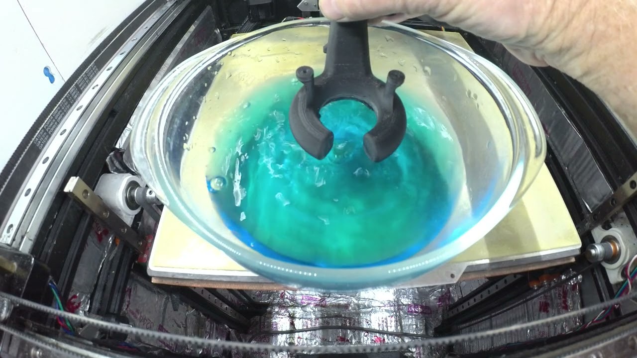
Need to make some iterations, cfd etc, but this is the vortex duct idea I had. I might put some small ports around the outside bottom for some extra part cooling goodness. One thought/concern I have is, will the air come out pretty evenly all the way around?
surreal blade
Wishing I had a cnc right now! Next project after the next ten are done I suppose. I have a scroll saw to cut out the aluminum and some files. Hard way it is 😅
 surreal blade


 surreal blade
Just messing around. Definitely has that spinning air. One thing I found interesting is when I put the block in the center it's almost like the water wants to move upwards towards the nozzle. 🌪️🌪️🌪️
 shut herald
surreal blade
Just messing around. Definitely has that spinning air. One thing I found interes...
This looks great
shut herald
surreal blade
Wishing I had a cnc right now! Next project after the next ten are done I suppos...
Hard way is the best way, cnc takes off all the fun
surreal blade
shut herald
This looks great
Thank you!! 🙂
surreal blade
I think only way to learn more is to do some simulations at this point.
teal jacinth
surreal blade
I think only way to learn more is to do some simulations at this point.
Or measurements, like pressure and airflow so you can know if you're hitting a sweet spot for your cooling solution
surreal blade
teal jacinth
Or measurements, like pressure and airflow so you can know if you're hitting a s...
What would you do? Something like an anemometer and manometer?
teal jacinth
surreal blade
What would you do? Something like an anemometer and manometer?
2 DIY u-tube manometers and a Venturi tube if you like DIY with printed parts
surreal blade
I could totally DIY something like that. Been wanting to make a manometer for a bit.
I remember seeing the Venturi tube when I was researching Venturi vacuum pumps/generators

only got like 14 inHg. fun project though
surreal blade

This is alum tube at normal length. Finished heat sink surround and mounting for it. hopefully it will be a nice solid/secure solution
surreal blade
Redoing and cleaning up the bottom half of the ducting for a smoother transition. might make a few that have different arrangements at the duct exit
surreal blade
Test

 surreal blade
form is better. one pic looks like a bottle lol. Going to do a similar nozzle exit as the last but thinner. Now that I am here a this point any thoughts?


 surreal blade
thanks for the help so far guys
surreal blade
next forge
You need a fancy name for the toolhead<:vaulthah:597787241812852736>
I keep calling it "the vortex toolhead or duct" whenever my buddy asks how it's coming along 🌪️
next forge
Sounds nice
surreal blade
The name fits that's for sure, thats something ive been thinking of for a bit
next forge
Storm in a Bottle but thats a mouthful
surreal blade

 surreal blade
next forge
Storm in a Bottle<:vaulthah:597787241812852736> but thats a mouthful
It totally looks like a bottle lol
surreal blade


 teal jacinth
surreal blade
I hope there'll be no gap like pictured on the section
surreal blade
teal jacinth
I hope there'll be no gap like pictured on the section
👍

could've combined geometry better but meh. first version of many
teal jacinth
surreal blade
👍
This gap
 surreal blade
oh lol no
I have an insert. just havent put it in the model yet
mze
My modeling is pretty rough until the last few
solid onyx
You will have some issues with an open duct 360°. The air will take the path of least resistance and most will exit the rear/near the 1st source of air to the duct. This may not be an issue at 100%, but it will where you need finer control. Also, when you have two air front collide, they can cause random shifting of the air stream, turbulence/loss of efficiency. With the UFO typ]e duct I made, I had to place outlets around the perimeter. I ended up at 4 ports + 2 bed coolers. 6 was too much for the amount of air available and re-sizing didn't make it any better. It's one of those things where you make some tests and iterate until it's more balanced.
Here is the UFO tested with water, like you have.https://www.youtube.com/watch?v=pVlH6EwoafY
 next forge
#1331733786286751795 message looks pretty good here🤷
solid onyx
By making the exit orifices smaller, you will increase the velocity. But if too small, there will not be enough volume and too much pressure, disrupting the models plastic.
solid onyx
I can give you the orifice size I use, or you can also download the files on thingiverse for the ufo duct. Then compare what the total volume out is. It's just another data point to play with. BTW, the outlets are not very big. There is a reason I opened the front. When connected, the two air fronts smashing together did not work. I had made another with a divider inside, then just opened it up later to this, so you can see the model printing.
There are some kewl ideas on the needitmakeit YT videos, where they tested some fan ducts. The different iterations were really neat, but IMO were not able to flow well. The ones that I saw were worth investigating and many with 'vortex' style.
There are so many ways to attack this and I applaud your efforts!

 surreal blade
solid onyx
I can give you the orifice size I use, or you can also download the files on thi...
Those pics are cool! Little things like that volume reduction are new to me as points to consider.
Headed to watch some of those needitmakeit vids
surreal blade
solid onyx
I can give you the orifice size I use, or you can also download the files on thi...
Checking out needitmakeit, this is some stuff I need to watch for sure!
solid onyx
Those tests didn't go over too well and the CPAP used was not WS7040. So there was never a model made, with those ducts, that was good quality. Then change ducts to see any apparent changes or tuned for the ducts themselves. So it's hard to get an idea of the effectiveness of them. But some of the concepts were awesome.
surreal blade
@solid onyx thanks! Also printing my other one and a new less restricted top portion to compare and check out. Need to sit down and start figuring out a cfd program. Is there one you would recommend? I've been playing around with Simflow and paraveiw a little bit.

My printer is lol! just needs to hang in there a little longer! Hang in there buddy😂😂😂

 surreal blade
@solid onyx just saw the fugly tornado duct. Interesting design! Some of those designs surprised me that they didn't work out as well as one would think.
solid onyx
I am not sure the tests represent much without proper tuning, baseline tests, and the right pump. There was one duct that stood out, I think I downloaded it, but can't remember the name. Anyway, at least you have a chance to get inspired and can compare some other duct sets to try.
surreal blade
 surreal blade
Final Inlet area is 185mm and each down tube outlet is 151.53mm at the lower duct attachment point. Cross sectional area of the cpap hose is about 185mm..


 surreal blade
Cleaned it up and opened things up a little more.
 solid onyx
surreal blade
Final Inlet area is 185mm and each down tube outlet is 151.53mm at the lower duc...
I think there is too much exit area if I understood what you wrote here.
IIRC, I am about 2:1 inlet vs outlet
surreal blade
solid onyx
I think there is too much exit area if I understood what you wrote here.
This is the spot thats about 151.53mm. Figured I would try and keep it free flowing as possible up to this point and then build different ducts off that point. it splits there
 solid onyx
(using WS7040 w/19mm hose)
You will need some high velocity out the duct's nozzle orifice. The time the toolhead is there may be to short, so the velocity trades for volume.
it's more about keeping that body filled with a little disruption as possible from losses in direction changes
If the outlets are too big, the duct will be very lazy at low throttle
I feel like I am tuning an engine
ha
You should be able to compare the UFO to yours by using a jewelry scale to measure the force on the scale. More does not mean better, but it's an indication of what is happening with air speed, just not where it's going.
surreal blade
Its a balance of orifice size and velocity as well right?
solid onyx
Creating a larger feed tube make the duct act shorter
like the source is closer
changing orifices exiting, controls the speed of the air and the volume. More volume, less speed/velocity
less velocity can help filaments that can be shocked by fan speed, but the larger you go the less control you have at low speed. So you have to balance the duct to a style/speed of printing.
surreal blade
solid onyx
You will need some high velocity out the duct's nozzle orifice. The time the too...
So its kinda like use the best duct that will supply the correct velocity and volume for the given print while also giving yourself the largest fan speed envelope?
surreal blade
solid onyx
You should be able to compare the UFO to yours by using a jewelry scale to measu...
I was definitely getting less force with my original vortex duct. I got about 8.5 grams with mine and 19 with the ufo
but I think the volume was to high so mabie not getting the velocity?
solid onyx
Yes. For instance, when I print ABS I need about 5% fan, functional print, 300-400mms/20K accel, 20SCV. Larger prints. 5% is too low, meaning that 10-15 would be better.
surreal blade
like the exit orifice size just to large
solid onyx
Or you might want to hear the fan un at X speed, fr noise levels, so you design duct that works in a more limited range.
solid onyx
surreal blade
like the exit orifice size just to large
or the angle is wrong or or or.. it get's complicated what the air does
surreal blade
lol so much to think about
solid onyx
Here is an example. Just because the exit orifice is angled at 45° does not mean the air will. The analogy is a baseball in a hallway. The doors are orifices and you throw the ball.

The 2 arrows are potential limits to the swing in direction. What chooses their path is the preceding 'hallway'
solid onyx
It's not a straight shot and those direction changes and volume changes make different speeds inside the duct.
The baseball analogy is pretty much it for the air path. Any deviation causes losses
surreal blade
I noticed that with the vortex duct it was pretty consistent but there were two areas that you could tell there was more velocity. below on the outside
solid onyx
get your duct setup so you can place a feather in the middle and see when the air bends it. Then change the duct so it hits just below the nozzle
surreal blade
from the outside
Ok!
makes sense!!! I will give that a go
Thank you for the stuff to think about
solid onyx
Carry the torch! Carry it strong!
surreal blade
And I will!
surreal blade
@solid onyx NOW I think I understand. I hope....At first I was perceiving what you were saying from a dimensional internal volume perspective at first, not volume of flow. So basically want to keep in mind the shape of the bends, or try to eliminate bends where possible, and aim for the straightest most direct route or (the preceding hallway in the baseball analogy), therefore reducing flow disruption. I'm using the same WS7040 and 19mm hose as well. So depending on the print you may want the highest flow volume and velocity without negatively effecting the plastic/print itself like for a speed benchy. So shape of the ducting and the actual orifice exit size will determine this performance. Some prints might require low motor/velocity speeds and given the type of CPAP blower and It's operating speed range the orifice size may be too big or too small. Depending on the filament If the orifice size is to large at the motors lowest operating speed it may be providing the print with too much volume and if they are to small the velocity might be end up being to high for some filaments that can be shocked by the higher air velocity. I think I see what you mean regarding balancing the duct to the plastic/style/speed of the print. So with some prints it's more dependent on range of velocity/volume and in others it's about getting the most cooling performance out of the system, all in the most efficient way possible.
Playing around with openfoam today. Well attempting to anyway lol. I'll figure it out at some point 😐
solid onyx
FYI, I make most of my ducts first, then do some water tests, ETC, revise. when I get close, I start to play with CFD. It's a tough thing to grasp, depending on the software. They have classes on it that take more than weeks to learn and is mostly an approximation. Where it really helps is to fine tune volume sizes throughout the duct, to have more even or evenly scaling velocity inside the duct.
The reason is you still have to make the shape fit, get the angles right for the lead in to the last orifice, ETC. And if you have tested ducts before you have some indication of previous experience to make changes.
The key to air flow is to navigate the passages MUCH before the final outlet, efficiently, effectively moving the hallway in front of the door. And for that you need space to do it. Hence the bigger, wider, ducts.
surreal blade
solid onyx
FYI, I make most of my ducts first, then do some water tests, ETC, revise. when ...
Makes sense. I'm thinking a little too far ahead. I can definitely see the cfd thing taking a while. Especially after looking into it more today. At least with openfoam. For me, even getting Openfoam running is something I need to figure out and then figuring all that out is another. I can get off track with all that stuff big time lol. Just need to think about getting the toolhead done and the printer refreshed then I can mess around with ducts more then.
I'm already thinking of improvements and other things after learning a bunch past few days
Has to wait though lol
surreal blade
Gf-abs adapter fixed to hose using some clear permatex rtv.
 surreal blade
 surreal blade
Little bit of work on the ducting exit. Hope to have more even flow and higher velocity by using angled vanes. have it directed about 5mm under the nozzle. I think the orifices might be to small but there's 6 of them. Might be able to make some adjustments with a file if I need to I suppose
 surreal blade
Sounds like the air fronts are shifting around. Trippy
Idk mabie it's common.
A lot of air is definitely hitting where the nozzle would be. Some of air is fanning out directly perpendicular to the duct. Can definitely tell on the right and left sides of the duct there is more velocity than there is front to back. Going to roll with it for now and see what happens. Getting some ideas for a non Vortex duct to make in the near future
surreal blade
Did a pressure test with the manometer with the cpap about 70% @ 20v. My original vortex duct read 5.2 inH₂O, Second version was 4in and the -ufo-n-ator- read 3.2 inH₂O. So if I am thinking about this correctly this tells me the ufo had the highest flow volume out of the 3 seeing that there was less pressure.
solid onyx
Cover the outlet in a garbage bag, remove all the air, time the fill of the bag, calculate the flow.
solid onyx
CAUTION Don't forget that you can have too much... I am re-designing UFO to give less air speed... it's too much for some filaments, printing slower. BALANCE! 🙂
surreal blade
Thank you! I'll definitely keep that in mind! I have one more design I'm cooking up with a shorter more straight path
surreal blade
Wasnt sure about the front mount. I think this will work ok once I put in some kind of vertical strain relief more on the back side of the tool head. Hose is a little bit in front of COM. My hopes are the angled hose helps at least a little with how the weight is positioned.

 surreal blade
Shrinking the downtubes so the internal volume of that section is less. Figuring out form in f360 a little more.
 solid onyx
surreal blade
this one looks good, keep the top end, mid body, and create from there down?
surreal blade
solid onyx
this one looks good, keep the top end, mid body, and create from there down?
Here's this one. I was going to have the splitter just stay on the tool head when I change ducting. Hoping it will make it easy to quickly swap out just the lower half of the ducting for when I want to try a new idea or for small adjustments. At the bottom of what you see here will be a flange of some kind to attach the bottom portion.


Will get some losses with the curves like you were saying, I hope it's not too bad. I like the look
 solid onyx
Git-R-Dun
surreal blade
trying to make it in a way so the view isnt as blocked, but everything I can think of seems like it would add losses. Ill bite the bullet here soon and do a single tube. I'm collecting parts for another printer, that will be capable of some really fast printing. Out right performance will be a bigger concern I think for that situation
solid onyx
Keep in mind that air is detrimental to prints. It's needed to go fast, but there is a tradeoff. Consider also, that when you print really fast, and the models shape has different densities of plastic in one place vs another, the cooling is extremely difficult to remain constant. The lower density areas will melt or have more shine than the others. Ideally, you want a printed model that will have the same shine.
I do speed stuff just to see what I can get away with. In reality, when I print for a customer, I don't FAFO!
surreal blade
solid onyx
Keep in mind that air is detrimental to prints. It's needed to go fast, but ther...
I've definitely blasted prints with to much air before! Learned the hard way with a big print that pretty much fell apart from bad layer adhesion lol. That was a bumber haha😁
Was also using a steel nozzle. And under temp. It was a recipe for un-success lol
surreal blade
v2 of the last one. Made the curves even more gradual than the last. Tried to do a better job modeling. Some reason I cant figure out how to make the splitter less tear drop/curved in if that makes sense. Just going to file it to a sharper edge at this point lol.


 surreal blade
 surreal blade
Looks interesting! Here is where I wish I knew cfd! The front tubes are shorter but off to the side slightly with how they connect. Hoping it kinda evens things out. I think it looks kinda cool😁


My guess is Ill have to put some kind of vane in there mabie. Who knows. Onward!


Will be doing updates on this one. Might have to reposition some stuff in there, but I think I'm rolling with it for now. I forget how many times I've said that. But I mean it this time!
surreal blade
Id like some kind of extra outer part cooling. It be hard I think with this duct. mabie I can add a single dedicated fan for that on the toolhead🤔
surreal blade
Would something like these fans for extra part cooling be advantageous enough that it would be worth doing?
 next forge
surreal blade
Would something like these fans for extra part cooling be advantageous enough th...
I think auxilliary sheet cooling fans on the sides of the printer would probably be better? Rocksalt has the Valvanator which redirects a bit of air sideways to have a similar effect to sheet cooling iirc
 sick trench
looks pretty neat, not sure how useful since it'd only blow straight on the bed
also I'd remove the mounting points from the left side of the sherpa since that's a socket not a hole and it might vibrate loose then you get all kind of artifacts from backlash
surreal blade
sick trench
looks pretty neat, not sure how useful since it'd only blow straight on the bed
I know what the hole is. It would have been fine. But im glad you got me thinking about it. turned out way better
surreal blade
next forge
I think auxilliary sheet cooling fans on the sides of the printer would probably...
I agree! I think that will be the way in the end. trying to come up with some kind of concept similar to the valves but not be the valves. Not sure how I could do that though. The valves are great because there just built into the duct. Simple and elegant. No extra weight or wires. A lot of the concepts I've thought about add a little extra weight. But would the benefits be worth it? Who knows. Some new idea is out there waiting to be discovered! Until then the sheet cooling seems like the best idea for sure.
next forge
Good luck🫡
surreal blade
sick trench
looks pretty neat, not sure how useful since it'd only blow straight on the bed
Looked at flow pattern with some smoke and yeah way too straight of a flow. Curious if I can attach something to make the air shoot out sideways. Who knows. I'm delirious lol! In reality the Aux sheet cooling fans are probably the thing I'll end up doing
surreal blade
sick trench
also I'd remove the mounting points from the left side of the sherpa since that'...

 sick trench
neat
surreal blade
cool
surreal blade
Flange or no flange🤔

cant decide if i want to split the ducting so i can remove the lower half or not
it would be a hell of a lot easier to print
surreal blade
bracing!! I think this tool head is going to be pretty solid.
 surreal blade
Happy with it so far!
 surreal blade
@solid onyx Interesting, the valve angle is more downward on the ufo than I assumed. Are you shooting for a specific cooling zone? I'm trying to come up with some kind of solution with the current design. I have some Ideas but with all the tubes and how they connect I have no idea how it's going to flow. I made the orifices in a way that I can file away material to balance the 4 down tubes. I tried equal length but the way the bends were it seemed like there would still be a difference. I tried connecting the tubes in a way that has a little less going to the front tubes because they are about 20mm shorter with less bend. Was also curious if you have ever used internal baffles to lower the flow for filaments that like lower air flow before?🤔


 solid onyx
surreal blade
<@840043656072396840> Interesting, the valve angle is more downward on the ufo t...
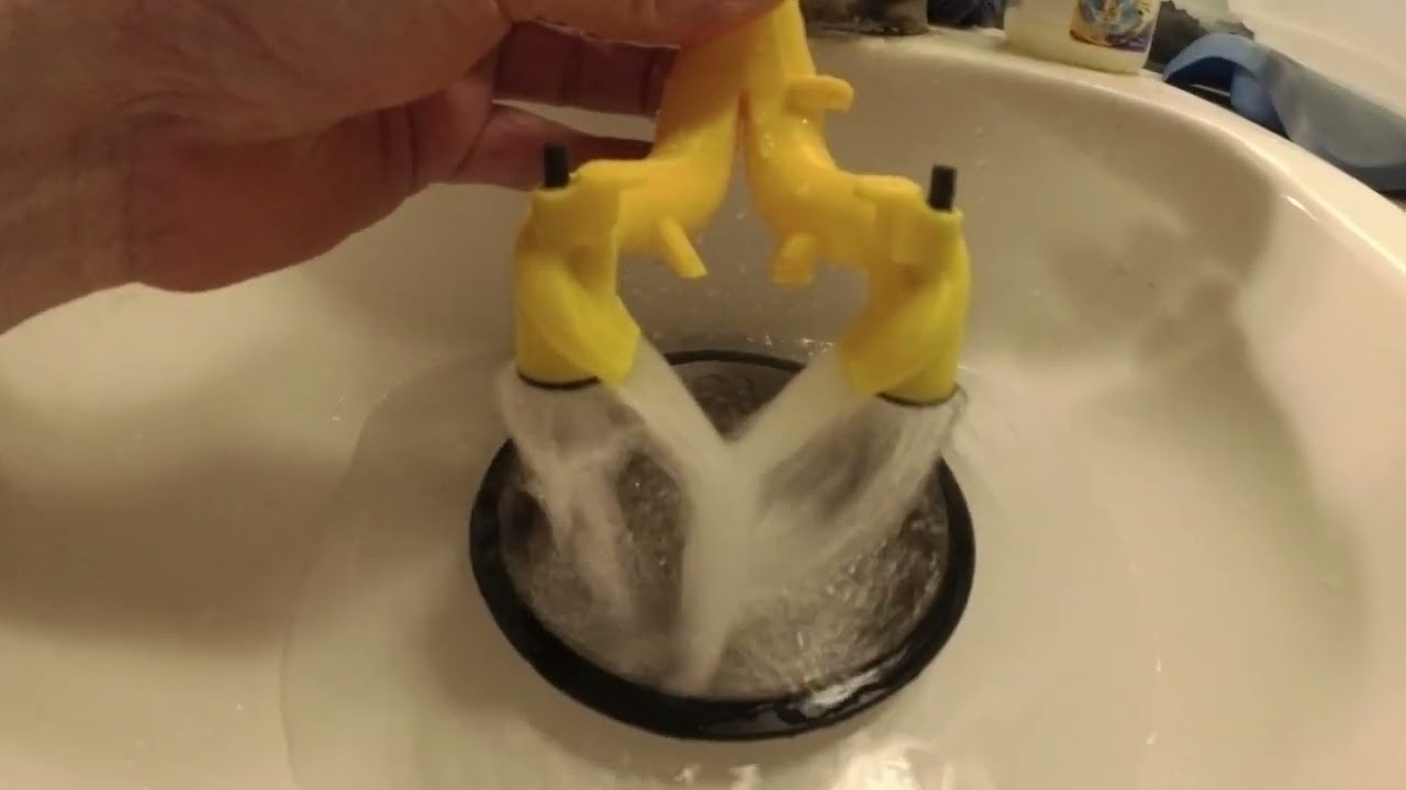
Simple is better. Narrow tubes are harder to get air through, more bends is more losses. But in reality, what is the goal; Your targeting a speed and material with cooling. The properties of the filament will determine the parameters. I prefer ~90% nozzle cooling and the rest sheet. But it depends on what your printing, how big it is, how much flow, ETC. I guess what I am saying is that the printing deficiency dictates the design of the duct. See what it lacks and go from there. The valves are meant to make an air curtain 360°, hitting the plate or other. https://youtu.be/XGb-C0MtduU
 surreal blade
solid onyx
Simple is better. Narrow tubes are harder to get air through, more bends is more...
Guess the speed goal with this printer is 200, 300ish max if I'm being impatient. Goal I suppose is more about having quality prints in that speed range. Still will try to get everything I can out of it. More is better of course, but I'd be happy if there was sufficient cooling for that kind of printing. I have no idea what it takes. Seems like with the right duct design the cpap motors can keep up with some really fast printing though
surreal blade
solid onyx
Simple is better. Narrow tubes are harder to get air through, more bends is more...
ha I was doing that earlier with all the ducts I printed out. Done that, used smoke, lasers, feathers, yarn, mica water, my diy manometer, the list goes on. Those techniques definitely help


 surreal blade
Thank you 😁 Almost there with it whew
solid onyx
I wanted a duct with 3 nozzle coolers and 3 valve's. The difficulty level of that is akin to the super boss in Mortal Kombat. The low speed air wanders, high speed is not enough to fill all the tubes. Night after night after week after week, iteration after iteration until I wore CAD out.
surreal blade
@solid onyx If I can even get the duct 90 percent there without cfd that would be cool, but I'm not very sure about all that. Simple is better, then I create this thing! It totally goes against the principles I've learned😅
surreal blade
 surreal blade

Tiny LED lights I found in my stuff! 3v 1/4watt. Suprisingly bright for there power

forgot the fillet
 sick trench
I wonder if you could get better com by routing the duct behind the toolhead
or would that result in too much loss in duct efficiency
for a bedslinger setup it might not matter much tho
surreal blade


 surreal blade
sick trench
or would that result in too much loss in duct efficiency
I am really not sure to be honest.
surreal blade
sick trench
I wonder if you could get better com by routing the duct behind the toolhead
Are you saying behind the toolhead like in between that and the extrusion or on the back side of the extrusion?
sick trench
yep
on the backside
if the toolhead moves in Y then it might give you better com and less vibrations
but if it's for a bedslinger and it only moves side to side it might not matter
surreal blade
meh next build is definitely not going to be a cartesian. Seems like its hard to get a good cpap situation going compared to corexy etc
I like cross gantry those seem pretty solid way to go
surreal blade
sick trench
but if it's for a bedslinger and it only moves side to side it might not matter
hope its not something that will be that impactful. I just couldn't vibe well with the hose coming over the top. mabie from a top heavy standpoint this could be better?
sick trench
it's probably fine
surreal blade
sick trench
I wonder if you could get better com by routing the duct behind the toolhead
Was having my coffee, staring at my printer and contemplating the other day about moving the x axis gantry forward somehow giving it the space needed to route behind everything. Or the z axis extrusions moved out to the side and have gantry in between the rails like on the lh stinger.
I might do the lh stinger style gantry actually
Seems like it would be better from a linear rail standpoint
Then I could route behind the tool head much more easily.
solid onyx
surreal blade
Are you taking part cooling for hot end cooling also?
surreal blade
solid onyx
Are you taking part cooling for hot end cooling also?
For the heatsink part? Using a seperate blower of some kind for that I think. I havent figured that part out yet really though. at least from a air supply stand point
there is this area where the valve air is blocked from hitting the nozzle area. I need to fix that actually
surreal blade
solid onyx
Are you taking part cooling for hot end cooling also?
This area? Between the two ducts? This is that one spot that was blocking some of the valve air.
 solid onyx
I saw the plastic around the heat synk, with a tube.. didn't know where the source air was coming from./
surreal blade
solid onyx
I saw the plastic around the heat synk, with a tube.. didn't know where the sour...
Ohh right on, I think a seperate blower of some kind will provide the air.
surreal blade
solid onyx
I saw the plastic around the heat synk, with a tube.. didn't know where the sour...
Was going to do the flap valve thing and have it connected b4 the valve setup for constant air but you talked me out of that haha
solid onyx
IMO, you should build a duct, get a model you want as a baseline, then print with some baseline duct, then compare with yours. Hopefully, the baseline duct is better than yours so you can work past it.
I think you are trying to do too many complicated things at once. When you get to test, it will be hard to break down what is where/why/ETC.
surreal blade
solid onyx
I think you are trying to do too many complicated things at once. When you get t...
I do feel like I am biting off too big of a bite lol
surreal blade
solid onyx
IMO, you should build a duct, get a model you want as a baseline, then print wi...
Im with you on that. This toolhead is almost done and the initial ducting is done. Until I get everything else going anyways. Then its back to the ducts😅
surreal blade
Think I'm pretty much at final assembly for a few things in fusion360. I hope. The black toolhead scaffolding? Idk what to call it. Going to print that out of gf-abs @100%infill. Going to try my best and cut/drill press/tap aluminum bits by hand and attempt to have it be within a decent tolerance.


 surreal blade
 surreal blade
Not perfect much less restriction


 surreal blade

Iteration to the last duct. For what it is, it seems like it would flow well I think. Want to figure out something for 360 cooling. unsure


Reminds me of a damn earwig lol .
surreal blade
Will post in show room when it's physically done. Thanks for all the help, especially @solid onyx . Thanks!
surreal blade
 sick trench
looks nice
surreal blade
sick trench
looks nice
Thanks! 🙂

Its going to flow all weird and uneven for sure. How weird is tbd 😅
surreal blade
Have to do a vid but actually doesn't seem to bad, in the sense that the air flow all converges where the nozzle should be. The tiny valves work, but they are too tiny! Minute some tiny thing gets hung up on them they will break😕apparently I've made this quite the journey lol 🤪
To much velocity it seems like if compared to ufo. Figuring out better ways to model these tubes. Was trying to do everything in tsplines at first. Definitely not the way!
 solid onyx
I forgot to mention that when I tried to put the valves separate, it didn't work and on most occasions. Almost as if the split inside does not work properly. Maybe the valve loft acts like a siphon or maybe the turbulent air at the split does not allow laminar flow and upsets the stream. For this I always put the valve in the same loft as the nozzle cooler. 3 was too many for the amount of air available with WS7040. Adding more valves removed some of the benefit of the valves.
surreal blade
solid onyx
I forgot to mention that when I tried to put the valves separate, it didn't work...
I was wondering about the siphoning effect. The way the last duct was, the lofts were a little weird. Everything lofted up to the same place, but the way some of it transitioned was questionable. The siphoning or very low flow seemed like that was actually a thing with the two front tubes. At least until the pressure rose in the system and it just kinda overrode the effect. Seemed like it anyways. But then low fan speeds wouldn't have worked as well I'm thinking. But yeah valves on last just too tiny and too many for sure. I always make the mistake of thinking things are bigger than they actually are when I'm looking at stuff in fusion360 I swear lol
Opening up things much more. more volume less velocity.
 solid onyx
the point of the valves is to target the lower regions of the model, lower than the nozzle. It is quite easy to see on a benchy.
Those valves attack the bow of the boat quite nicely and the need not be opened too far! Maybe only 1-1.5mm.
The point also is that they are not meant to work at low speed. 90 nozzle, 10 valves. Maybe 80/20 and they are curtain air.
If you see my test videos you can clearly see 2 rings below the valves and they push the water up in the center from displacing the air further out.
I always felt I needed at least 3, evenly spaced on a circle. And since I want my valves in the same loft as the nozzle, it will make 3 nozzle and 3 valves. But there is not the right pressure in the duct to keep it filled at lower speed and even high speed is not as good at 2.
Here is a 3 valve, 3 orifice, but the valves are separate.
https://www.youtube.com/watch?v=7jJgy3kGWxo
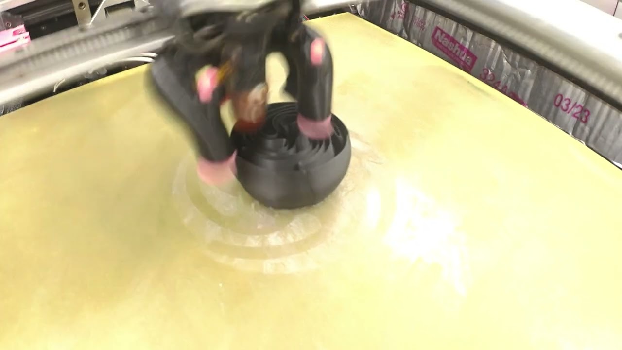
17mm wide, 10T, LDO stepper motor @48v
Goliath hotend, VZhextrudort lowered
315C Temp ABS, .4 CHT nozzle, .4 line width
1000mms commanded, 60SCV(Jerk), 60K acceleration.
~50-54mms3 flow
3.5 minutes, 1 line width print(Vase mode)
I am running out of flow with .4 to go faster.
Keep in mind the set speed is 1000mms, but the machine has to slow do...
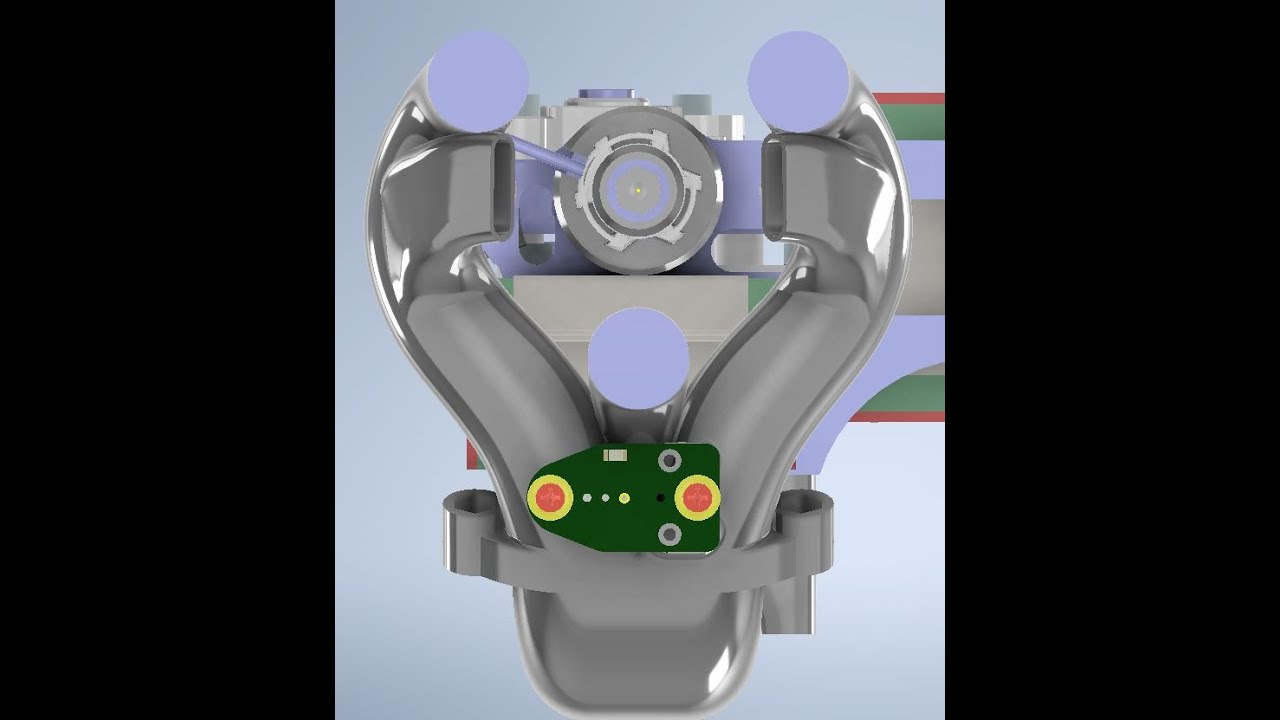
That one was not bad actually, but at some time I noticed something and went back to 2 valve.
solid onyx
Sorry, that is 3 valve, 2 orifice
surreal blade
Ahhh I see. Last one i made, it fanned the air out more horizontally. Less cone shaped than the ufo or what I'm seeing in the vid. Hit under the nozzle more than the nozzle duct but also suffered from being too restricted over all and the valve ratio was more like 3%valve/97% nozzle. Makes more sense why they are more for higher speed smaller models I'm guessing? Bigger models that have more time for the last pass to cool, the valve would have less of a noticeable impact then it seems like. Like they probably help some but less suited.
surreal blade
solid onyx
BTW, those ducts flow >100GPM
Dang! I still need to try the trash bag method to figure that out
solid onyx
But it's a style choice. Large flow can work and also high velocity, low flow
There are more limits to the high velocity version, It's a stronger type duct, more reactive.
Tradeoffs with each style
surreal blade
I'm happier with this one. Converged things a little differently. Outer Dia. of valve tube is 14.2mm

 surreal blade
seems like the back duct will flow a little more even though its slightly longer bend. Hope its not too bad

 surreal blade


I like it. Adjusting the valves will be a little different. I'll need to make spacers or just reprint for the best length on those. Internally the valve stem blocks the rear nozzle outlet a little. Originally I was imagining the rear nozzles might get more flow on low fan speeds but mabie it wont be as much. Who knows, time to print!
 surreal blade
suspicious
 surreal blade
As I kinda expected. rear nozzles had way more flow. Was like 70/30 very uneven. hoping with the last section being straighter now it will fix that or help. Might just do a single nozzle for each side instead of two
 surreal blade
 surreal blade
sick trench
how are you holding the valves in?
Still not really sure, printed in place sounds like a good idea tbh. More simple and the valve stem is no longer a factor
surreal blade
sick trench
you could also try Colphaer's duct
Thats one way, honestly I became kinda fond of the print in place idea! Wasnt thinking about that for some reason. Glad you put it in my head 🤯 ha!
surreal blade
sick trench
you could also try Colphaer's duct
Imagining the print in place would just interfere less internally. I was also looking at the duct and didn't like how long the valves would have ended up. thanks for the idea 🙂

 surreal blade
 surreal blade
Another day, another iteration lol! I dont know what i'm doing half the time so thank you for all the help!
sick trench
I don't know either what I'm doing so don't worry
print and let's see it rip some layers 
solid onyx
surreal blade
yup, tried this also. Nothing worked as good as a traditional valve to allow the air to flow over the tulip. And you have the brace in the direction you want the air to come out. Ideally, if you have to have a PIP duct, with a way to hold it, then the air is better to be able to exit any direction but towards the nozzle.
I also see a mini tube there, inside the other tube. Those don't work well. The boundary layer is too wide and flow will not want to exit there, taking the past of least resistance.
surreal blade
solid onyx
yup, tried this also. Nothing worked as good as a traditional valve to allow the...
Cool, thank you! Whats your thoughts on the pip but with a longer valve stem tulip? Would that be better? Is it a laminar flow issue? I can imagine the shorter tulip point might confuse the flow a little compared to a longer one or full length. Idk if I'm thinking about that correct
solid onyx
You want the air to blend over the tulip and exit. When adding objects in the air stream it has a dynamic effect on the air at different speeds. I did to a PIP duct, but sadly it has not been fully tested yet.
This is why I suggested simple paths. It's tough to get working what is in your mind vs reality.

doesn't work, yet.
Simple often works and tunes easier.


 next forge
I call it: The Squat
sick trench
looks interesting
 surreal blade
Keeping this bit. redoing the valve shape a little for hopefully better coverage. making it less squat, going back to longer gradual tubes
 surreal blade
As far as this section goes, for what it is, I just dont know how I could make it better with what I know so far😮💨


less squaty. couldn't hang with that lol
 surreal blade
updated this part. cleaned it up, reworked valve. On to figuring out how to mount it


 surreal blade
sick trench
you already have airflow going at the nozzle
It's kinda aimed about 10-15mm below where the nozzle air hits. I wanted to free that area up a little more for slightly better 360 coverage. Did put that tiny divider in there. could add like a mm to each side. Not sure how much air flow really ends up making it to that spot. Just with how the internal nozzle scoop geometry is. I'm unsure
surreal blade
sick trench
you already have airflow going at the nozzle
 surreal blade
sick trench
easier with a test rig
Thats a good idea.
Been working on this handheld fog machine thing be perfect for some testing
surreal blade
surreal blade
 surreal blade
If I can get this orifice/valve combo situation working good it seems like it would be pretty cool. Did a water test through it and it's doing what I expect for the most part. need to make some adjustments here and there to get the flow ratios right and play with how the valve seats to optimize cone angle etc

Remodeling middle guide fins to contour the valve shape, squeezing sides a little more to tighten up nozzle cooling path and improve ratios

and who knows what else

 sick trench
surreal blade
If I can get this orifice/valve combo situation working good it seems like it wo...
the attention to detail with the fiberglass sleeve
surreal blade

@solid onyx Have you ever tried a variable valve? Where the valve stays seated until blower is past a certain amount and then it opens up slightly.
vtec lol
solid onyx
surreal blade
Remodeling middle guide fins to contour the valve shape, squeezing sides a littl...
This is not what you want. This is what will happen :

Did we talk about the baseball in a hallway analogy?
solid onyx
surreal blade
<@840043656072396840> Have you ever tried a variable valve? Where the valve stay...
There are so many things you can try. I have not thus far.
surreal blade
solid onyx
Did we talk about the baseball in a hallway analogy?
Yes, I see it now. Mabie some day I'll mess with the variable valve
latest iteration would have done the same dang thing

@solid onyx 👍
surreal blade
Seems good. Air hits where the nozzle would be. Where nozzle cooling converges, seems like half the air is going up and half going down. Gets some part cooling coverage but only like 225 degrees to the sides.
 surreal blade
I mean seems good enough to mess with I think. The biggest reason I did this is because I wanted the nozzle cooling orifices aimed more at each other right at where the nozzle is. More horizontal. Seems logical to me, then again half the stuff I've thought was a good idea wasn't lol. I'm trying to become one with the air particles!
next forge
 surreal blade
next forge
https://tenor.com/view/avatar-the-legend-of-aang-the-last-airbender-anime-the-fo...
😁
solid onyx
surreal blade
Seems good. Air hits where the nozzle would be. Where nozzle cooling converges, ...
It looks good, my concern would be the valve leaks too much air and opening/closing the valve could greatly impact the nozzle air. But.. just thinking.. no idea practically. For me, a benchy would tell me a lot about the duct's performance. But not the tell all. The benchy needs a lot of air, if fast, and regular models will need less. Bridging and overhangs need to be tested also. With UFO I am roughly 20-40% only.
surreal blade
solid onyx
It looks good, my concern would be the valve leaks too much air and opening/clos...
Already changed it back to kinda like how the valvnator is. The valve thing is genius! Trying to brainstorm some kinda neat idea that is unique to my design, but it's been a challenge. It's already pretty damn practical the way you have the valve concept figured out ! Learning to think in terms of how fluid flows better in the process has been pretty sweet, also a challenge lol. More I learn, more I keep seeing things that can be improved from a physics standpoint. I'm also in a battle with trying to make it look like it's not humping the extruder or twerking while maintaining practical performance oriented design choices🤣
surreal blade

Am I being stubborn about puting the duct more over the top lol?

Got the connection point almost right over the COM now, moved it up slightly and tilted it a tiny bit more. Instead of having middle tube in front I just moved the split all the way up to the top for more gradual bends. Moved lower portion of the ducts out more to make bends even more gradual and provide more room to have the nozzle cooling orifice more horizontal/ opposing each other.
 solid onyx
I don't know what to say! You change your design every 2 days!
surreal blade
solid onyx
I don't know what to say! You change your design every 2 days!
Uh, I'm just conversating and complementing your valve design. It is your concept right? Like I said it's genius. At least that's my opinion. Already really great how you have it figured out👍 trying to imply that it's been difficult trying to reinvent the wheel. So to speak. Cheers! 🍻
I'm annoyed with the constant redesign. I don't normally feel the need to do that.
Learning something new from each design I make on top of trying to conceptualize fluid dynamics on top has led to lots of iterations lol
solid onyx
My design is not ideal. But it does work better than some others... It was a new concept, at least to me when I designed it. But I made so many iterations over a year my head was spinning. You might be missing out on something good in one that is not in the 2nd, ETC. Empirical testing will be a data collection phase. Took many tries to make alight bulb!
surreal blade
solid onyx
My design is not ideal. But it does work better than some others... It was a ne...
I understand the head spinning lol
surreal blade
solid onyx
My design is not ideal. But it does work better than some others... It was a ne...
In the end I find it enjoyable though. It's all pretty interesting stuff
solid onyx
It is! Bottomless pit if you let it!
surreal blade


 solid onyx
That red line is more ideal path, but width can be a constraint. Wider is better as it more gradually shapes the air. Above, in your pic, the air comes straight down, then has to make an angle change abruptly. It will work like that, but might not aim properly. But will probably show more with lower speed air, on details. At higher speed it might be OK.
The thing I wanted to work the most is 3 valves and 3 nozzles. But this balance is hard to get working right.
 surreal blade
solid onyx
That red line is more ideal path, but width can be a constraint. Wider is better...
Printed one to test out. From what I'm able to tell it seems to have nice nozzle air convergence. Different air speeds is something I need to think about more. Will have to see how it prints. In my mind I imagine the air path angle shifting downward slightly as the air increases. I can't even imagine tuning a triple valve situation. With just two I've noticed it takes a little filing here and there to get things more even. I'd imagine with three, cfd is more mandatory to get things right.
solid onyx
You can use water and watch the water displacement at different speeds. Even sand, but messy. You should print those other ducts and have a show down on 3 different models, attacking different type of features. Tune the base duct for each, then compare the new ones. But don't expect to use the same gcode! Different type ducts might need different speeds.
surreal blade
solid onyx
You can use water and watch the water displacement at different speeds. Even san...
This latest one I'm settling with for sure sure lol. Figured I'd make this one and work off of it as a base to improve upon. For the arrangement I think its kind of a win in the performance dept except for those last bends. The look I'm not very fond of though lol. Tried to do what I thought was the best shape for the air with it being up front like that, being two prong, getting connection little more over COM etc. Did a few small things to make the print turn out better. Other than that it's printing out at the moment. Will make another one that's wider with less sharp bends at the exit like that to see what happens here in the near future. I haven't compared flow volume but I did compare pressure and it's definitely the least restrictive out of all the ones I have to test. Getting some numbers on volume here soon is on the list.
surreal blade
 surreal blade
Test print #2. want to print some different valve profiles. Other than that everything else is coming together. Need to figure out some kind of mount for the bed probe

I love gf-abs

Except for the dangling glass fibers that sometimes manage to find there way into my skin. I wear gloves but I swear it's like this stuff leaves little fibers everywhere
 surreal blade
Lol
surreal blade
sick trench
looks nice, those valves tho
Lol they are longer than they need to be. Did it for adjusting but didn't need them THAT long lol
surreal blade

They still long

dang, just relized I forgot to put the holes in for the heatset inserts
solid onyx
The divider looks great, but might need more volume from the split to the 2nd bend. The valve profile looks to need to be improved. Look at the valve design of an engine and the 3 angles. I shape by hand, the valves and the seat. The valve needs to be centered to work right and not open very far. You can print a benchy and speed it up to where the bow fails, then open more to clean it up. (close the valves complete, then print a PLA benchy until the bow has signs of curl, then open more, print, repeat.) Should end up ~1-1.5mm open, but not more. If you open too far, the bridging and nozzle air speed will be too low and you will see signs of cooling issues/curl on corners and overhangs. If you don't have enough nozzle cooling with the valves open 1mm, then the main nozzles are too big.
surreal blade
solid onyx
The divider looks great, but might need more volume from the split to the 2nd be...
Messed with it for a bit trying to make it more gradual, but I also wanted it to go from curves to straight down or at least lined up with x axis as soon as possible. Even so there still is this twist action to the water and it doesn't come just strait down. With the nozzles on and the valves in everything seems to do ok as far as what I'm able to perceive with the water flow test and water dish. The valves totally need some work. Want to make them shorter over all and improve the profile. The top connection id is 19mm and where nozzle portion bonds to the top half, that seam is 16.5mm for each tube. I think for the loft it is a linear reduction in size until last 20mm then its just strait. Totally should make it wider and the the nozzle path straighter. It would also make for @sick trench shorter valves. With those longer thinner valves they aren't as strait and precise as I would like
solid onyx
Here is a view of how mine looked.
2nd iteration of the multicolor duct. Better angle of the exit orifice and lead in to the last orifice. Previous version's aim was not far enough to the nozzle. One piece duct with only 2 lofts on the main body. Turns made more gradual to reduce losses.
it's a lot of air...
But it does not work with valves alone.
surreal blade
solid onyx
Here is a view of how mine looked.
https://www.youtube.com/watch?v=e7e2nip4eyE
Right on, its good to see that. I was thinking earlier about the ratio of nozzle air to valve air. Mine just needs a little more air on the valves and it would be sorta close. Cone angle on current version very similar after I reprinted the valves. Not sure about volume. Its a tiny bit more volume I think than the ufo duct when i compare current draw and pressure, but less main nozzle velocity. All I'm going to do at this point is slight angle adjustment for little bit better path, beef up valve seat area and valve a small amount so I have a little bit more to shape. The long thinner valves are kind of a pain to get centered and precise. Should be able to figure out shorter valve stem situation with slightly more angled ducts so win win. I think that should be the last few things or close
solid onyx
You will get it.. just takes time and iterations. And when you think it's all good in CAD, the real world tests fail! haha
surreal blade
Angle adjustment is done. Beefed up valve seat area and made the valves less long lol!


Tried to get it lined up with the Xaxis up high enough that it gives the air a little more time to straighten out a little. Not sure, seems to make sense!

 next forge
Love how this went from: "Hey I had this hotend machined" to "Duct Design: Every step"
surreal blade
next forge
Love how this went from: "Hey I had this hotend machined" to "Duct Design: Every...
Didnt plan on this! But hey here I am lol! Feel like this is the duct. At least to start with. Just hope it doesnt do anything weird lol
next forge
its probably fine
surreal blade
I'm rollin with it! Feels like a good culmination of what Ive learned. Finishing this thing up so i can move on lol
sick trench
"finishing" and "moving on" heh 
looks nice, add a brace to the bottom then test drive
surreal blade
 surreal blade
sick trench
"finishing" and "moving on" heh <:Kappa:333641571524411403>
ha when its this stuff it doesn't seem like ever lol
next forge
Welcome
surreal blade
Brainfart, it's a rivnut insert so looks more like this where the lower part of the duct attaches.

Have these aluminum nylock nuts I could even use to really lock things down. Already gave those attachment points little more material around the rivnuts than whats in the picture.
solid onyx
surreal blade
These lines are really good. Flow test it and see if it can get into the 90's GPM wise. That long narrow section will eat a lot of flow.
surreal blade
solid onyx
These lines are really good. Flow test it and see if it can get into the 90's GP...
Thank you😁 Have more of a final version printing. Just some small tweaks for better print.
surreal blade
Re-worked heatsink cooling surround, beefed up a few things and worked on strain relief bracket. Doing some cleaning up on the printed duct with some sand paper etc and that's almost done. Need to figure out the probe mounting scenario and then pretty much at the point where I can start using the tool head once it's all put together. Now it's on to working out the real world kinks and other random little improvements


 surreal blade
Seems promising from what I'm seeing so far. Need to mess with valve seat so the valve can be more recessed. Need to do something about how the flow comes out of the valves. There is a difference with the side of the valve facing the nozzle. Flow is stronger there than the outward facing sides. Seems to flow tons of volume though. Need to get one of those big bags so some comparisons can be done.

 surreal blade
Finally able to mess with it a little bit. Had an issue with how the air was coming out of the valve. Had a lot to do with the internal path with the bend and then how it was a strait shot to the part of the valve facing the nozzle. Seem to have fixed it about 80%. with some messing around with the internal geometry. Just went with print in place valve. But instead of having just a strait valve stem It's shaped it in a way to help direct the air in a more favorable way. Not a hundred percent sure but mabie cause less internal drag, idk. Printed it out and its ready to go! Did a few small checks, ran some water through it for some flow visualization and checking it with a dish of water etc. Happy with it for the most part from what i can see. Now it's about printing some benchys and seeing what happens woo! 


Might open up the valve more in the future. Just going to print with it and see how it goes . If it does good then great!
surreal blade
Probe mount done

strain relief done. Originally was just going to have it solely incorporated in with the cnc sherpa. Felt like it needed extra stability/rigidity.


These little guys seem pretty sweet! Should make it so I can get some good torque on the fastners for the motor and the duct mounting. Seem like they would work alright.
 surreal blade
 green lichen
You should mount the k face for your Sherpa mini
Thank you for suggesting that! I need this!
surreal blade
Volume testingish.. not entirely sure of the exact bag size.
On average it takes the ufo duct about 26 seconds to get from folded up to full. About 113 gpm I think if it was 50gal
This one was a little shorter. Always seems to fall somewhere in between 25.5 to 26.5s
 solid onyx
Making progress! Flows well, time for testing prints?
surreal blade
solid onyx
Making progress! Flows well, time for testing prints?
Hopefully some test prints in the next few days
surreal blade
solid onyx
Making progress! Flows well, time for testing prints?
I just need to fabricate the aluminum parts and put it all together. The aluminum stuff I've been putting off till last. I have a scroll saw, drill press and files. Half tempted to get the more complicated parts machined
solid onyx
I do them all the time with those tools. If 2D, then easy. If not... well.. I weld, whatever, to get it done. SLM if needed, but not often unless it's technical, like an extruder.
surreal blade
Going to give a good try! I think it should be ok if I just take a little time on it.
 surreal blade
Vids of just designed duct. Did an average of four runs each. If my math is right I'm getting a very rough 130gpm and the ufo duct is around 120 gpm with how I ran the test at least.Out of curiosity want to do another test with the first duct I printed out a month ago to see the difference. Guessing it's flows at least 1/3 less volume haha!
One more test vid of the ufo duct
sick trench
surreal blade
looks like some ancient clay artpiece with this color
surreal blade
sick trench
looks like some ancient clay artpiece with this color
My buddy said basically the same lol, he said it looked like a mysterious artifact you would see on ancient aliens
surreal blade
surreal blade
Vids of just designed duct. Did an average of four runs each. If my math is righ...
Alright did these test wrong. After some thought relized I should have the cpap fully going and then quickly attach the hose instead of starting from off to on. Spoolup time of the motor I would imagine throws the numbers off. Also relized it was a 30gal bag. Was wondering why the gpm numbers seemed so high. dang errr lol
solid onyx
I was going to say that the 7040 has a GPM of ~112/from datasheet. But comparing 2 ducts shows relative to each other. Spool up is ~1 second, so just subtract the 1s if you want raw flow. Appears the UFO is 75PGM. I think I get 90GPM IIRC. So the hose length might be it or the diameter of the hose(still using 15mm hose?)
surreal blade
solid onyx
I was going to say that the 7040 has a GPM of ~112/from datasheet. But comparing...
Using the 19mm hose now and It is still full length at the moment. Great to know those numbers. I remember you saying try for 90gpm. Happy that it seems in the same range .
solid onyx
In that case you could have an issue. Test the flow with no duct to be sure that with the duct it is less flow. You need a bit of back pressure so the duct can be pressurized, and make more velocity at the expense of some volume. This will allow for better lower speed operation as you won't be printing at 100% fan speed. The UFO duct is too powerful for ABS at slower speeds. I have to dial it way back, something like 2% and that can be too much. But 2% is 12% IIRC, as the min speed is 10%.
surreal blade
solid onyx
In that case you could have an issue. Test the flow with no duct to be sure that...
Say you wanted to have less volume and velocity for ABS. Could one do an ABS mode device with a bleeder valve mabie? Idk, mabie different positions on it to set it exactly how you want? I print a lot in those ranges. I was curious about your thoughts on that. Did a few test with tube only and averaged 97GPH. I sealed up this 1 inch spot that was in the bag. Mabie that threw it off some?
One of the tube only test.
Just did this test with ufo and it seems about 75-76.

Unrestricted it's within spec but not by much.

Going to reprint the ufo duct. It could be possible xy contour comp was being used when I printed it the first time by accident.
surreal blade
Have to wait till later to do some comparisons. Almost sure xy comp was being messed with when I printed it the first time and just didn't notice.
Dang lol
 surreal blade
solid onyx
I was going to say that the 7040 has a GPM of ~112/from datasheet. But comparing...
Ok getting more confident in the numbers. The reprinted ufo duct is getting average 82-84 GPH.
solid onyx
GPM! (~21s for 30 gallons, 21 into 60, 3x, 3x*30=90 napkin math)Considering I have the pump on top of the top hat, the hose is ~14"(355mm). From your last test it's at ~85.7GPM (22s., -1s for spool up). Raw hose for me is ~117GPM and you are ~19s with hose at (94.7GPM). So maybe should shoot for 70-80GPM if you can't get the air up to 115.
Something to note: The valves in the UFO duct do not work near as well as the valve duct. I have not gone back to try and make them better. That UFO duct was a 2 week, made from scratch, effort. The valves can be tricky! They need not be opened too far. The are treated as AUX air, so to speak. Opening them too much will result in a loss of nozzle air, so you have to play with how far they are out and perform a few tests. I did mine based on my build/hose length/tests prints. There can be a loss in performance if the hose is longer or smaller diameter.
teal jacinth
solid onyx
GPM! (~21s for 30 gallons, 21 into 60, 3x, 3x*30=90 napkin math)Considering I h...
Ufo is great from my perspective, and considering it was a 2 week project makes it even more impressive
solid onyx
teal jacinth
Ufo is great from my perspective, and considering it was a 2 week project makes ...
When I get into something, my 2 weeks is probably 4 weeks, LOL. OCD to death.. wake up in the middle of the night to add bright ideas from sleeping to see if works. CooKoo..
surreal blade
solid onyx
GPM! (~21s for 30 gallons, 21 into 60, 3x, 3x*30=90 napkin math)Considering I h...
Wow, GPH thing was a big brain fart haha! Once it's all together I can see what kind of impact the full length hose has VS cut shorter.
Not sure how much I need to cut off just yet. Getting this kinda big steel shelf unit I'm converting to an enclosure here In about a day.
Ok just managed to test my duct out and was getting about 87 GPM
Here's a vid of one of those test
surreal blade
solid onyx
GPM! (~21s for 30 gallons, 21 into 60, 3x, 3x*30=90 napkin math)Considering I h...
One of the things on the list is definitely printing another duct where the ratio of valve to nozzle is slightly higher. One now just seems a little weak in the valve department compared to the ones you have done vids of.
Have a k-face for the sherpa on the way along with another Fysetc cnc. Need to figure out a solution for the k-face to screw into.
Doesn't seem like there is enough material for the face to screw into. It will but the threads just sit so close to the bottom surface of what I have the heatsink mounted too. Not sure what to do with it
 solid onyx
Make your own motor support in the rear, now you have 3 points in triangle.
surreal blade
solid onyx
Make your own motor support in the rear, now you have 3 points in triangle.
That's a great idea
I will give that a shot!
@solid onyx Kinda like that already no? Have screws going down and ones going through to the back using square nuts in that space.

Tried to have everything as integrated as possible.
 solid onyx
No way to get that support piece center of motor?
You want to stop the motor from bouncing. That front plate might be better in your arrangement, but trapping the rear is stiffer.
solid onyx
surreal blade
Not a fan, but I didn't run any FEA to see. The motor mass is the largest, so it can act, from the moment, against those forward bolts. I mount from top rail, so I have many places to secure the motor.
surreal blade
solid onyx
No way to get that support piece center of motor?
Need to do some head scratching.
Need to to think about how best to do that. I can see having that back peice extend up to help out. 🤔
surreal blade
sick trench
you could also integrate the sherpa mount into that alu plate
That's a pretty cool extruder situation. I can see something similar but do like your saying and use the alum plate. I like this idea. Need to do some contemplating!
solid onyx
surreal blade
Need to do some head scratching.
Maybe the K face is the best option. I think I spoke too soon, not realizing you had front mount. I noticed right away with vzhex, the movement/bobbing of the extruder and just bolted down in the rear. Can't move now at all! If the extruder body is plastic, put the hold down at the rear, if metal, probably good with the K face.
surreal blade
solid onyx
Maybe the K face is the best option. I think I spoke too soon, not realizing you...
Right on cool to know! I still think it would be cool to figure out something with the motor mount portion like that. I cant even imagine the g forces with the mass of the stepper. Probably lots if the acceleration is high.
surreal blade
Getting this put together. Needing ventilation and want to split it into two heated enclosures. Still a lot work to do on it. Adding 2" alum angle for the corners and getting some cross bracing tomorrow.
 surreal blade
update pic. works better than I could have hoped for

putting a heater in there soon, then on to fixing up my trident
 surreal blade
made a 24-5v pwm signal voltage regulator, isolator and conditioner! Plugs into fan out on board, then into cpap driver board. seems to work pretty well all less than 50mA. get full range and can dial the speed down to being able to hardly feel it flowing at all. yay🙂
 surreal blade
went way to long without these carrage attachment brackets. always just used a printed part.

 surreal blade
will upload a schematic once I get one drawn up on the signal buffer thing for the cpap fan driver signal. basically it's a voltage reg to reduce voltage 24v to 5v, optocoupler(pc817) for the 24v pwm fan out from my skr3,through a Schmitt trigger to the cpap driver. here's a better picture. middle terminal out to cpap driver, terminal by optocoupler plugs into fan out on skr board. voltage reg powered by the separate 24v ps for cpap. cheers


 next forge
surreal blade
will upload a schematic once I get one drawn up on the signal buffer thing for t...
@teal jacinth
Thoughts?
surreal blade
things that can be improved. mabie a reverse voltage protection diode and prob few more things besides my meh soldering
teal jacinth
surreal blade
will upload a schematic once I get one drawn up on the signal buffer thing for t...
That's the tacho or the PWM?
surreal blade
teal jacinth
That's the tacho or the PWM?
pwm
surreal blade

 coral frost
Have you done volumetric flow rate tests with this?
 neat trout
Does it work
neat trout
coral frost
Wow that dope brother
surreal blade
coral frost
Have you done volumetric flow rate tests with this?
Going to deep dive into it more tonight and see what it does
surreal blade
neat trout
Wow that dope brother
Thanks!! had some delays but glad it's finally up and going!
neat trout
surreal blade
Thanks!! had some delays but glad it's finally up and going!
Perfect brother
surreal blade
coral frost
Have you done volumetric flow rate tests with this?
it's close to giving up at around 30 with this PLA. This PLA+ I have started getting pretty bad around 22. Both temps at 225c, 0.4 brass volcano nozzle with a melt zone extender. I'm cool with that for a first design. my biggest regret with this design was not making the block longer, instead of using the melt zone extender.
coral frost
surreal blade
it's close to giving up at around 30 with this PLA. This PLA+ I have started get...
Nice! What extruder are you using? Could that be limiting it a bit too.
next forge
Dude what is this beltpath
next forge
And its different on both sides?
surreal blade
coral frost
Nice! What extruder are you using? Could that be limiting it a bit too.
using the fysetc cnc sherpa
coral frost
Oh nice!
surreal blade
next forge
Dude what is this beltpath<:vaulthah:597787241812852736>
lol ye it's the belt tightening mechanism. definitely a v1 design issue. I want to figure something out with that.
green lichen
surreal blade
lol ye it's the belt tightening mechanism. definitely a v1 design issue. I want ...
Isn't this the tightening mechanism?
 solid onyx
surreal blade
will upload a schematic once I get one drawn up on the signal buffer thing for t...
These are really cheap if you don't want to assemble/solder/ETC.
https://www.amazon.com/dp/B0CPJGFCGR?ref_=ppx_hzsearch_conn_dt_b_fed_asin_title_1
Working voltage: 3.3V - 12V
Working current: 9.5 - 21.5mA (no-load test, actual use may be slightly higher thanthe test value)
Input signal level:+3.3V -+24V (PWM high level is+3 .3V -+24V, low level is 0V)
Input signal frequency: 22Hz- 20kHz
Output level: 0V - 5V/0V-10V
Allowable output...
surreal blade
green lichen
Isn't this the tightening mechanism?
it used to be, all solid now. I want to get rid of that thing. I don't like it lol. using the tightening mechanism on the tool head at the moment. I want to design a more elegant solution for this pulley so all that stuff isn't there anymore, and the printer will take up less width. might even trim off a little bit of the 2020 to bring the pulley in more for making the printer more compact and shorten belt length.
surreal blade
solid onyx
These are really cheap if you don't want to assemble/solder/ETC.
https://www.ama...
oh dang! thanks! I just ordered 2!
surreal blade
green lichen
Isn't this the tightening mechanism?
still may do awd at some point. the list just never ends lol
surreal blade
@nimble badge nice enclosure! mine is kinda similar. Still a work in progress. I regret not going with 1.5in thickness. went with 3/4 insulated walls. it stabilizes around 38c. just got a ptc heater. need to get that working here soon


good thing I don't have pets or kids 😅 all this is getting some tidying up!

 nimble badge
surreal blade
<@572132720013082651> nice enclosure! mine is kinda similar. Still a work in pro...
I find it hard to believe it only gets to 36C! What’s the ambient temp outside of your enclosure?
Even in my unheated (for the moment) house it is 10C ambient outside the enclosure, and gets to 56C ambient inside with 20x28x28in internal dimensions
I do have 1in thick FIR though
I guess your door is hardly insulated so that maybe makes sense
coral frost
surreal blade
<@572132720013082651> nice enclosure! mine is kinda similar. Still a work in pro...
Buy another E3 bed and put it in there.
Should help you get some more heat.
The Derra Way™
surreal blade
nimble badge
I find it hard to believe it only gets to 36C! What’s the ambient temp outside o...
ambient is normally around 23c. There are some tweaks I definitely need to do. Hinges need to be sealed or redesigned and those doors almost seem like they get just as warm on the outside as on the inside lol.
surreal blade
coral frost
Buy another E3 bed and put it in there.
genius lol. I totally have an extra one!
surreal blade
coral frost
Buy another E3 bed and put it in there.
I'm curious how that would do in a trident. I just got a ptc heater for this thing.
surreal blade
nimble badge
I find it hard to believe it only gets to 36C! What’s the ambient temp outside o...
printing past 6 hours with some abs and it settles around 44c. those doors have to be the culprit
nimble badge
surreal blade
printing past 6 hours with some abs and it settles around 44c. those doors have ...
How large was your enclosure?
Mine would only get to 34/36C when it was huge, but now that I took half of the space out it gets to 56C. Wired up a heater today, about to find out how to setup klipper to set the chamber temp
surreal blade
nimble badge
How large was your enclosure?
it's 20x21x21
nimble badge
surreal blade
it's 20x21x21
That sounds about right then for ambient temps, since our system enclosures are around the same size, but mine has better insulation + better door seal, and gets to 56C
Also it looks like your floor isn’t insulated which is pretty important for a small enclosed space
surreal blade
nimble badge
Also it looks like your floor isn’t insulated which is pretty important for a sm...
3/4in insulated as well under the hardboard. I need to hook up the ptc heater I just got and figure all that out. still have some of the reflective bubble insulation. think I'm going to line the doors with it and just have cutouts so I can still 🧐 in there.
 nimble badge
surreal blade
3/4in insulated as well under the hardboard. I need to hook up the ptc heater I ...
I think I was looking at this heater but opted for a different one that was 400W, and smaller form factor.
How do you plan on regulating your enclosure temp? I have been learning about high AC voltage lately and just need to buy a better SSR so I can use klipper to regulate the temp
surreal blade
nimble badge
How do you plan on regulating your enclosure temp? I have been learning about hi...
I was thinking the same with the ssr. I need to dive more into the heater side of things. chamber fan is up and working
surreal blade
v1/v2 GF abs y pulley. tried messing with vapor smoothing it. meh.
 surreal blade
coral frost
surreal blade
I thought that was a miniature version of one of those guys that waves around outside of some dealerships.
surreal blade
coral frost
I thought that was a miniature version of one of those guys that waves around ou...
it could work! if I was in a mall or something and that thing was flying around, it would definitely grab my attention lol
surreal blade
was using an aquarium air pump to keep the heatsink cool in the toolhead. too loud. it's nothing fancy but using this now at 1/3 power and its really pretty quiet. just put pwm to 5v voltage converter in there. I was messing with the potentiometer every print for the past few weeks and that was pretty annoying.


 solid onyx
surreal blade
was using an aquarium air pump to keep the heatsink cool in the toolhead. too lo...
Looks familiar! Make sure you check the output before you connect to the CPAP controller. The input voltage affects the output. I can't remember what source voltage I used and had to tweak that pot.

Maybe there wasn't a pot and I had to set limits for max and offbelow. Heh, bad memory.
surreal blade
solid onyx
Maybe there wasn't a pot and I had to set limits for max and offbelow. Heh, bad ...
Just got back from taking a sanity break with it lol. Mabie this is related to the issue I'm having! When I first fire everything up the fan just sits there and randomly starts and stops. Looked at the pwm signal coming in and it looked fine. About to dive into it more
solid onyx
I am using 2 of them and they have been working well. You only want output of 0-5V. You can leave unconnected, then put it at 100% and make it so max out is 5V. Then set the offbelow so the min is 1%.
surreal blade
solid onyx
I am using 2 of them and they have been working well. You only want output of 0-...
cool giving that a go
solid onyx
I feed the board 5V from octopus to the board and use these settings. Mine doesn't have the jumpers, but a solder pad. I didn't solder mine and the output is 10V, so I limit the max power in .cfg.

 surreal blade
solid onyx
I feed the board 5V from octopus to the board and use these settings. Mine doesn...
not sure what's going on. it's seeing an alright pwm signal and it's powered with clean 5v, but the output is weird. tried with jumper and no jumper no effect.
surreal blade
solid onyx
I feed the board 5V from octopus to the board and use these settings. Mine doesn...
 solid onyx
What voltage is there at 100%?
surreal blade
solid onyx
What voltage is there at 100%?
goes full 5v when at 100% seems anything less gives me that crazy output
solid onyx
What voltage do you get at 15%?
I didn't scope mine, just used a volt meter. I can scope mine also to see what it looks like.
Another thing I don't remember, is if I used the 5V from the CPAP controller or external supply. Ideally, better to use the 5V in the CPAP.
solid onyx
surreal blade
Use the min_power instead of off_below
surreal blade
solid onyx
What voltage do you get at 15%?
when it's at 15% there is no output from the converter
solid onyx
50%?
Try the settings I have.
This is the second one for brushless motor driver. No solder pad soldered, 100% is 10V and .13 min_power makes it run at 1% commanded speed.

10%

100%

50%
 surreal blade
solid onyx
This is the second one for brushless motor driver. No solder pad soldered, 100% ...
are you using danger klipper? heater_fan doesn't seem to have min_power
solid onyx
It's in kalico main and bleeding edge
it's a must have for me.
THis way the fan runs at 1%, so the slicer doesn't have to mess around with min speed
if you set off_below to 10%, this means that a command of 5% will do nothing
I think I have a file changed to get min_power from klipper main. I need to look for it. Before they made it standard in kalico, I had a edited file to fix it. But now since it's in Kalico I don't need to bother with it.
PWM. 100%
 surreal blade
solid onyx
I think I have a file changed to get min_power from klipper main. I need to look...
I'm going look into this more. at 50% it's just the weird signal again. going to power it off the 5v with the driver and see how it goes
surreal blade
solid onyx
PWM. 100%
interesting. the signal I get from my skr3 when at 100% is basically 100%pwm or 24v and at 0% no pwm signal. your 100% looks like my 50%

 solid onyx
what is the source voltage applied to the controller?
surreal blade
solid onyx
what is the source voltage applied to the controller?
5v
surreal blade
second board tried a 2k resistor thinking mabie was driving it to hard with the 24v pwm but still the same results
 surreal blade
going to check with my function gen and see what happens
solid onyx
PWM, 100%
I just hate that you are having problems. They have been solid for me.
According to that spec sheet, 24V PWM is OK.. and I thought you were powering the board with it.
surreal blade
solid onyx
According to that spec sheet, 24V PWM is OK.. and I thought you were powering th...
that spec sheet must be wrong. with it still powered with the 5v supply it works with a 5v pwm input just fine, but with a 10v or 24v pwm it just gets the weird output.
explains why yours have been fine
solid onyx
Glad you have it working! Maybe they meant to say 10V in means 10VPWM, not sure. At least you can continue.. Write that review!!
At least you didn't blow the boards up!!
surreal blade
solid onyx
Glad you have it working! Maybe they meant to say 10V in means 10VPWM, not sure....
they definitely didn't like the 24v lol
they survived so there is that 😂
solid onyx
I almost said "at least you only paid 10 bucks"
surreal blade
Almost! They are pretty inexpensive. I'm just suprised and happy they survived the journey
surreal blade
still think think this cpap muffler filter enclosure thing turned out pretty functional considering. had the project box laying around and the filter material from past projects. the box size is 158x80x60 and the ws7040 fan is in there. Probably design something fancier later. not as much static pressure as the aquarium pump for the heatbreak cooling, but the system doesn't seem to have the static pressure requirements for such aquarium pump. works good and much more quiet with this fan at 1/3 power.

 surreal blade
@solid onyx thanks for joining me on that learning experience lol.. I forget why I didn't use the dc mode module when I originally put this console together. I should have noticed this like a year ago and recently. was looking at all these pwm circuits n shit and got tunnel vision I guess lol. everything is up and going at least. still have the dc module on the way n just swap what I have going now when it gets here. cheers!
solid onyx
No problem! dc mode module?
