
#DoodleCube Lindwurm Build
1 messages · Page 1 of 1 (latest)
 slate bough
Right
So currently the XY&Z are able to move freely
Y rails are satisfying and sturdy. Also act as a brace for Z screws

Holes will mount belt tensioner assembly and Y block to extrusion
 vocal raven
Dual carriages for Y, nice
 gaunt dagger
Wont the Z axis need to move slow since the xy frame is top havy cause of the y stepper motors ?
and hope for you the 3d prints are super stiff so your gantry doesn't swing...but maybe it's just right/enough !?
 simple island
what is the goal? Portal printer with multiple portals?
vocal raven
simple island
what is the goal? Portal printer with multiple portals?
Might just be large format
slate bough
Goal is for large format prints, ye. Mostly automotive
Eventually I hope to get 2000mm rails
slate bough
gaunt dagger
Wont the Z axis need to move slow since the xy frame is top havy cause of the y ...
Nah. Normal flow rate will be fine. The rails and mounts are chunky enough to handle above ender 3 speeds
gaunt dagger
well then keep us updated ^^
slate bough
Y belt tensioner finished

belts will rotate on steppers pointed vertical, and I will need to design some pretty chunky motor mounts.
Now, for the reccord, the railfac is a less expensive version of my AAM Aero design, which again was much nicer. I originally planned to use normal rails with plasma cut steel or aluminum brackets. The railfac however will be easier to modify and scale in X and Y. Many of the original designs in the aero were tested on the railfac and have been replaced or improved.
 slate bough
 normal gull
Muktple heaters I assume
Either multiple or a custom one
Keenovo does offer custom heaters
vocal raven
slate bough
Either multiple or a custom one
Zone heating might be good here
 dull ingot
Blast shield 💀?
slate bough
used my sermoon to test Y
slate bough
View of idler

Also, I am using a cut of used 6mm gt2 belt that is from an old laser cutter I built that was tangled, so it's quite rough.
The Y axis works but has issues that need addressing.


Here is the motor block. I plan to add endstop mounts onto the motor blocks. On my TronXY Veho rebuild I put the endstops on the Idler side which just means more wire is needed and it's less organized, so putting the endstops and motors on the same end is obviously cleaner and plain better.
The endstop mount happens to be in an easy to modify spot
Also, as you can see the belt tensioner block is too thin, causing the belt to pull in. This must be corrected.
New belt tensioner block

new motor block with endstop
 slate bough
I would like to use closed loop steppers for this project. Unfortunately I believe that will be a later upgrade. What are good open loop steppers you all recommend?
Who am I kidding we all know the answer is LDO
slate bough
LETS GO SHOPPINGGGGG YAAAASS
BOM for AAM Railfac (1Meter version)
Frame: OpenBuilds 20X40 Extrusion: $45.98 for 2 1500mm lengths of extrusion and $15.29 for 1 cut of 1 meter 20X40 extrusion, total of $61.27 for the frame extrusion.
Duet 3 Main Board 6HC $276
E Series Steppers in set of 3: $16.53 via stepperonline. already have both Z motors.
Product description: Package includes: 3 x 17HE15-1504S Electrical Specification Manufacturer Part Number: 17HE15-1504S Motor Type: Bipolar Stepper Step Angle: 1.8deg Holding Torque: 42Ncm(59.49oz.in) Rated Current/phase: 1. | Product model: 3-17HE15-150
i will need more GT2 belt. will go with 6mm cause the stresses involved are not significant tbh
probably will need more cast brackets and hardware.
Oh actually
Y should have brakes
Now- I have a few ideas for the main electronics compartment. I could try to fit it all in on the sides. the frame will be 1500mm long while motion system is 1000mm. so i got 250mm on each end to work with, or i can cheat it one way or the other. OR I could mount the electronics above the machine on a wall or something. that way the cables to the gantry wont be in the way- which is something more to consider here cause the whole assembly moves around a whole meter in Y.
there may be two electronics compartments- one for the beds and one for the motion system electronics and hotend
i do not know how to power all these beds and motors withing a single breaker...
vocal raven
420 mNm stepper, 2 m long 6 mm GT2 belt. At 115 N the belt experiences 0,5% elongation, here we have 65 N so a bit lower, that gives us 0,3% elongation, so 6 mm of elongation if you use full stepper potential. If you tolerate only 0,5 mm elongation for example, then you're limiting yourself to using 1/12th of the stepper torque
normal gull
I guess this is one of the few times a drag chain and proper wires for it make a lot of sense
slate bough
Aye good points from both of ye! I will use 9mm belts and I should design a 2nd tensioner block with a drag chain mount.
Temporary braces until I can get the proper extrusion for the frame.
 normal gull
For 9mm belts you will need beefier hardware
vocal raven
slate bough
Aye good points from both of ye! I will use 9mm belts and I should design a 2nd ...
Get "GT3" (2MGT on Filastruder), it's thicker and hence it's stiffer (by a lot, at 115 N it has only 0,33% elongation compared to 0,5% of GT2, both numbers for 6 mm wide)
slate bough
normal gull
For 9mm belts you will need beefier hardware
Well, the belt tensionsers on here already are too thin and don't line up properly so I'm making new ones.
vocal raven
slate bough
Well, the belt tensionsers on here already are too thin and don't line up proper...
You'll want live shaft idlers instead of "normal" ones
slate bough
I haven't had any issues with the 9mm belts on the VEHO rebuild
I might look at the design of that to adjust the idlers

You might need to elaborate on live shaft- I'm a modix tech i never used those before
vocal raven
slate bough
I haven't had any issues with the 9mm belts on the VEHO rebuild
If you're getting typical idlers, they'll have bearings with ~300 N dynamic load rating. 9 mm 2MGT will want up to 150 N of tension. Since it's a 180° turn, the acting force will be 300 N.
Let's assume load is equally shared between bearings, so 150 N per bearing.
That's 8 millions of rotations till predicted bearing failure. Might seem like a lot but that's only 320 millions of linear movement in axis. Assuming half of the printer movement is done in X axis, with 0,4 mm LW, 0,2 mm LH you're looking at 60 kg till you need to replace all idlers. And that's assuming perfect working conditions.
slate bough
Do you have an example of a live shaft idler?
Ah I see

And then 2 bearings in a pillow block
vocal raven
slate bough
Ah I see
Use a normal idler, these tend to chew up the belt
slate bough
Aye
slate bough
So it would seem that the hole spacing on these rails is 22mm not 20. I will probably have to reconsider the frame design.
 vocal raven
slate bough
So it would seem that the hole spacing on these rails is 22mm not 20. I will pro...
So, if you enlarge each of these holes by 2 mm and use washers, everything will fit?
slate bough

New frame. 2040 on each end, 2020 down the length of the rails on the outside holes, and will have crossbeams down the center
slate bough
Redesigning X axis motor mount to position the belt directly above the X axis rail. First prototype does not fit, adjusting to correct that
 vocal raven
slate bough
Redesigning X axis motor mount to position the belt directly above the X axis ra...
Flip the pulley on the motor, position the belt as close to the stepper face as possible
slate bough
vocal raven
Flip the pulley on the motor, position the belt as close to the stepper face as ...
Thats what I plan on doing
I'm actually short on motors so this is one of the old Y motors I was using to test Y
My goal is 5 fresh 48mm for each axis
slate bough


New X parts
Y drag chain mounts look alright
This is not the drag chain I will be using, I will be buying a larger one
Drag chain will need to fit ZA,ZB,X,Hotend,Therm,PCollingFan,HCoolingFan,Probe,Extruder Motor.
Somehow...
If I use 8 conductor wire it might work
I may beef up the frame also
normal gull
Look at IGUS cables. Those are rated for use in a drag chain and available in a lot if configs
slate bough
Now sits on 6 rubber feet

 slate bough
So Railfac is consistent with my normal naming convention but I may rename it the Lyndwyrm as this is kinda a proper reinterpretstion on that original concept
Also X is in

Belt needs replaced
I might honestly redesign the X Idler and motor mount
Cause I designed them without considering the hight of the toolhead...
normal gull
Mh belt path looks like it could get pinched at the ends of travel?
slate bough
It's kinda rough, here I'll take another picture
It doesn't jam but it's fugly and I hate it

 normal gull
Usually you want a straight belt path on your mounting points, or so I have been told
slate bough
Lol yeah, I fixed the Y so it's nice and straight
normal gull
slate bough
It doesn't jam but it's fugly and I hate it
Yeah looks not ideal
slate bough
Looks like I need to raise the motor mount and idler
normal gull
Looks easially fixable though
slate bough
Yep, new parts will sort it
normal gull
slate bough
Looks like I need to raise the motor mount and idler
Or redesign the x mounting plate
slate bough
Yeah, I'm still trying to figure out my toolhead design
Not sure if I want a EVA-esque design or similar to my own LGX-ACE mount
normal gull
Try flipping the belt mounting 180º
slate bough
🤔 I haven't thought of that before, I might try that
normal gull
slate bough
🤔 I haven't thought of that before, I might try that
or carve a belt channel in the existing design
If that makes sense
slate bough
ye
i like the idea of inverting the mounts so the belts are slung under the extrusion. good use of space thats usually wasted
Or I could design a new Idler and re-use the X design of the V-minion
So many good ideas!

 slate bough
Right so with these braces in I can begin designing the bed. I plan on using machined MIC6 aluminum. I will be designing the bed and sending it to a machine shop. I think keenovo does custom bed heaters

Keenovo Flexible Heaters Store
Description: This listing is for payment purpose only. It is NOT for any particular Keenovo Silicone Heater. Please do NOT make purchase before contacting us, or it will be cancelled. We must have messaged a lot when we send you this listing. Please only make payment as instructed by one of our sales representatives. I
It will be some time before I do this, as it will be expensive. I want about 2-4 complete bed plates with heaters. That way if anything goes wrong in the future I have spares. Realistically I will probably get 2 first, then a 3rd if I think it makes sense to.
slate bough

 balmy plinth
is this a gantry slinger
vocal raven
balmy plinth
is this a gantry slinger
Yes, moving portal
balmy plinth
i hate it
vocal raven
balmy plinth
i hate it
Why? What else would you do?
normal gull
slate bough
Love it😁
 smoky geyser
balmy plinth
i hate it
A lack of appreciation for portal printers 😔
normal gull
Also you could easily||-ish|| add a second portal
simple island
normal gull
Also you could easily||-ish|| add a second portal
real easy yeah 😅 , like that one from autodesk forgot the name
balmy plinth
vocal raven
Why? What else would you do?
everything moves
simple island
the bed doesn't move
balmy plinth
positive Y the gantry moves, negative Y the bed moves
slate bough
balmy plinth
make it.
Bro its a meter
slate bough
Aye thanks, this is one of my best builds yet
I'm really happy with the rails I selected for y, very smooth
You can flick it at the top and it coasts
slate bough
I ordered these motors yesterday and got them today at 10:50AM. These are 48mm. Now, this is me, so within a year or so there will be a closed loop or full servo upgrade.
 slate bough
Alright, how should I go about heating the bed? i was thinking a single custom bed heater, but sections may be more ideal.
(and easier)
balmy plinth
sections because you can indvidually heat parts of the bed
and its probably more easibly sourceable
 normal gull
slate bough
Thats going to be a pain to solder up
Or you get one of the screw terminal ones
You still have 7 pins left for power and ground a few more if you choose a z probe thats not 4 pins
slate bough
normal gull
Thats going to be a pain to solder up
ngl my excuse is i get to drink, listen to music and solder 70 pins some wonderful upcoming November Sunday 
normal gull
Go for it then
 primal dagger
this is why I assemble Nyoomies myself x3
Music + Soldering = relaxing time
slate bough
normal gull
You still have 7 pins left for power and ground<:vaulthah:597787241812852736> a ...
Speaking of, you think the pins on a D-sub connector are large enough for heater power? Thinking 60-80watt
balmy plinth
"high current loads such as heaters not connected via D-sub connection"
i
maybe would not
normal gull
slate bough
Speaking of, you think the pins on a D-sub connector are large enough for heater...
?awg
 nocturne masonBOT
slate bough
Speaking of, you think the pins on a D-sub connector are large enough for heater...
 normal gull
Check the rating, I would spread it over a bunch of pins
slate bough
balmy plinth
"high current loads such as heaters not connected via D-sub connection"
FUCKIN SEND HER BUD
slate bough
YEAAAHHH
 slate bough


Well it's in, tested the pins, none are shorting, solder joints are serviceable. 18 gauge wire is adapted to 20 gauge solid for a cleaner joint on the motor pins
I will admit, it's not perfect, and I may redo it in the future, but it's not shorting, and a temporary situation like that often becomes the permanent. Maybe once I switch to closed loop I'll have an excuse to fix it right
slate bough
Portal bus cable connection- allows you to disconnect everything on the portal from the main bus cable that then plugs into electronics box

 slate bough
-- UC320-1--
Universal control box 300x200mm
slate bough
Right, so I am at the point where I can start working on the control system. I intend to use a separate power box containing PSUs and the control electronics
slate bough
box
 slate bough
Toolhead bracket!!

 slate bough
Bed frame is complete, need to print the mounting blocks.
slate bough


Bed mounted
(1 of 4)
Also tested an easy transportation solution. Portal will lock, and the entire fame can be lifted off its feat an roll on coasters, like a dolly

Tested single roller, works great, so once the 2nd one is mounted it should be sturdy enough.
That being said though I will be careful as a single parking lot pebble may change that


Also, i did this a while back for Y and have one for Z & X i am yet to print
I am still so undecided on how to wire this thing. The beds will probably be controlled separately, but there are still two Y motors and two Y endstops to control so I am making plugs for each and then I can design multiple main busses for the wiring.
balmy plinth
slate bough
Also tested an easy transportation solution. Portal will lock, and the entire fa...
shouldve gotten leveling casters
slate bough
balmy plinth
shouldve gotten leveling casters
Leveling casters?
balmy plinth

has wheels and rubber stops/feet to lift and lower
i use them on my printer, i can hardly move it
normal gull
balmy plinth
i use them on my printer, i can hardly move it
Shouldn't the wheels allow you to move it? ||I understood what you meant ||
slate bough
balmy plinth
This thing is long, it sits on TPU feet that are 100x20x25mm. I don't intend to move it around much, plus in dolly mode I don't have to bend over to move it
I will probably use leveling casters on one of my other projects though
slate bough
 normal gull
I can see a powerbrick strapped to this and wheeled through a convetion while printing
 surreal vortex
normal gull
I can see a powerbrick strapped to this and wheeled through a convetion while pr...
nah a 500ft long power cord dragging around the convention tripping everybody up
slate bough
Waiting on connectors & board
slate bough
Swapped Y belts with lead screws
normal gull
4 m of belts had a bit too much play?
slate bough
Aye, wayy to wiggly
slate bough
Testing a different belt system, motors on Y blocks. Speeeeeed
I'm gonna get new photos soon, but simply put my plan now is two separate gantrys I can swap between. One for laser cutting and one for 3D printing. Bed will be removable
Frame will be absent of most electronics except for the bed
normal gull
You could just keep all gantries on the machine and attach the one you need to the belts
or screws

 surreal vortex
slate bough
you were so close to servobelt
but omega drive is also good
now you need double shear tho
slate bough
Servobelt?
 vivid burrow
slate bough
Servobelt?

A short video of our new belt drive. Performance makes it competitive with linear motors at far less cost. Particularly useful for packaging, NC wood routers, NC water jet cutters, NC plasma cutters and all large format automation.
balmy plinth
servobelt is honestly so cool
 slate bough
vocal raven
slate bough
Nice
normal gull
Still a super awesome project
vivid burrow
nice to see it coming together
you are running RRF right?
should be easy enough to pass on the print coords from the slicer to the printer and reassign the active bed heaters to whichever will have the print on it

 slate bough
 normal gull
LyndWurm because its so long?
 vocal raven
slate bough
I love seeing this printer with other stuff for scale
vivid burrow
same, the grey/orange also gives it a great industrial feel
normal gull
Hope you got an ultrawide screen for slicing
slate bough
Aye, btw while you are all here, my probe is acting all funky. Wiring is correct according to sources on Duets docs & fourm posts. But I'm getting solid red and unresponsive after stsrtup
Probe was configured via reprap configurator
Wait..

Blue & yellow may be backwards
Still solid red..
vivid burrow
I haven't used a crtouch so no clue sadly
I know there's some differences between it and bltouch
slate bough
well it seems there is no info on it, so in the trash can it goes, and an actual BLtouch is on the way. normally I would actually try to solve the issue, but its just an old used probe. Had this thing on my VEHO for years, even after it crashed bad twice
slate bough
It is also a laser
 simple island
please make sure to stay safe
slate bough
simple island
please make sure to stay safe
Don't worry, I know what im doing with lasers. Did lasercutting before 3d printing actually
Unprotected fiber ain't nothing to scoff at. Especially this particular head
Can't remember the wattage, but it cuts through 1/2inch like butter
slate bough
K so, the reason the CR touch wasn't working:
6HC has 10 IO ports that are marked to be used for Z probes and other IO stuff. I had mine in IO3, but moving it to IO4 worked, because apparently only IOs 4-7 are PWM compatible
Wiring is almost done actually. Just thermistor and heater. Feels weird to be this close to done.
slate bough
Tiny little test boots for testing portal electronics without full track
 slate bough
I am still doing research on this issue, but i have a known good thermistor here thats reading 159C at room temperature for some reason
surreal vortex
slate bough
I am still doing research on this issue, but i have a known good thermistor here...
could it be the wrong sense resistance in the config?
slate bough
new therm works instantly
slate bough
 slate bough
The table shakes lmao
Also I want to do another version of the blocks with more fixing points to the portal
normal gull
It lives
vivid burrow

slate bough
I made a macro for nozzle change, which will be handy since I plan to use this for the TPU kei truck mudflaps also. Jogs to top corner for easy access and prompts for maintenance complete before jogging back to park and cooling down
I got a bunch of mosfets for the next 3 bed heaters. I don't actually know how much the control input can take on these shitty amazon modules, but I got like 10 of em so I can find out the dumb way. Can any output be a bed heater signal provided its being externally supplied and driven via mosfet?
normal gull
slate bough
I got a bunch of mosfets for the next 3 bed heaters. I don't actually know how m...
You can trigger the mosfets with fanports for example
So yes
slate bough
Rad
vocal raven
slate bough
I got a bunch of mosfets for the next 3 bed heaters. I don't actually know how m...
Which modules?
slate bough
Awaken ye thread
So as of last month I have moved
I have a house, which has garage and 3d printing space, which is fantastic for me cause I can do stuff now
Lindwurm will have a dedicated space, and i plan on running drop down ethernet for it
Im starting to wonder if the portal mounted electronics is dumb or not, and I might redesign the Y to accommodate metal laser cut brackets, but I donno.
First things first, I am preparing to get this thing running again and I am going to run some tests
Oh yes it also needs part cooling
slate bough
vocal raven
Which modules?
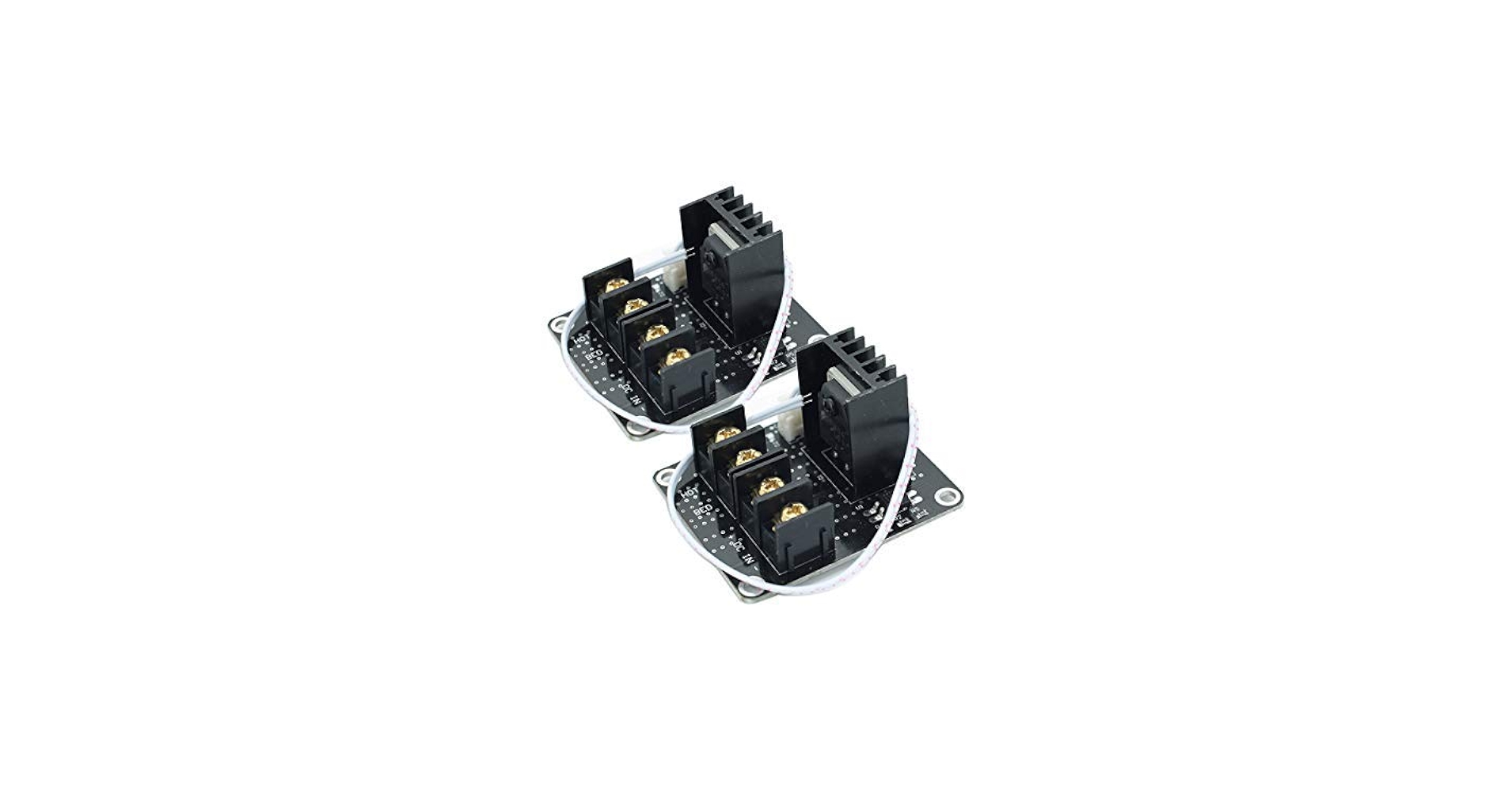
DEVMO 2PCS Heat Bed Mosfet,3D Printer Heat Bed Power Module 3D Printer Board Expansion Board 25A MOS Tube High Current Load Module
slate bough
I have no idea if I should migrate the electronics from the portal to the frame or not
Its running rn so I dont want to touch it, but maybe during an overhaul someday
Realistically the portal when this is all working only has 18 conductors that dont terminate on the portal and those are bed therm and control wires plus power. Otherwise I have my toolhead, fans, touch probe, two Z and one X motor plus X endstop
And thats 31 conductors
I might kill the independent PSU box idea and just run two PSUs and dedicate one to bed power
Its like 1200 watts if I tried to preheat all the beds at once
slate bough
DoodleCube Lindwurm Build
Railfac is not as cool as Lindwurm
I want to find out how fast i can make this gantry move
normal gull
Glad you are back with this awesome project
slate bough
I am going to start construction of a MK2 portal. I want the portals and frames to be mostly independent entities
I would say the theme of the lindworm is swinging big heavy gantries as fast as possible for long distances. Next portal will have aluminum cut brackets for mounting to the rails....or maybe I could just drill extrusion...I donno, custom plates would look much nicer
slate bough
I want to use a core XZ system to reduce motor count. I want to copy the bed motion system of the Antithesis 3.1 but I dont have a good visual on how it works.

Also I need to build an Antithesis
I will order the aluminum parts with the metal lindwurm rail truck parts
vocal raven
slate bough
I want to use a core XZ system to reduce motor count. I want to copy the bed mot...
Is this just a T-bot?
slate bough
Is it?
Holy shit thats what its called
Thats it
I kept thinking it was just some inverted core xy
vocal raven
slate bough
I kept thinking it was just some inverted core xy
T-bots are more of bent up H-bots
 vocal raven
Better graphic
 slate bough
Well alrighty
But aye I think this is what im going to use for the next portal
I still need to decide on how im going to design this. Should I prioritize rigidity or lightness?
vocal raven
slate bough
I still need to decide on how im going to design this. Should I prioritize rigid...
Depends on the target speed and load
slate bough
lindwurm aluminum brackets are go

My intention is two full rail trucks consisting of two plates and two linear bearings. I could also just do one plate per side if I need to. extra holes for motor blocks, whatever they may look like
slate bough
I may or may not have borrowed the toolhead from the mk1 portal for a laser/plasma table build. I will need to order more of em. The mk2 portal will not need the toolhead plate, I am proceeding with the T-Bot XZ design.
Still waiting for brackets from send cut send. Once I get those the rest of the new gantry will start.

 slate bough
 slate bough

Oh yeah. This time I know what im doing. Its going to be a T bot. The extra extrusion there is going to be where the board sits. There should be room for the top of the end effector to pass. The short side extension is for cable management for communication to the beds/board power.
This might be a good opportunity to learn about canbus
One board could do motion and another just worry about the beds
slate bough
Designed motor blocks, printing em tonight
slate bough


Oh we are cooking
Here is the old V1 motor block. I will be using heat inserts again to install the idlers as I had no issue last time. Tension should be identical


 boreal hawk
slate bough
K so a few things: while it fits its tight because I forgot to add .30mm of tolerance to the motor mount. I also am considering making a cavity for the endstops because I think if I do better cable management I can afford the 4 extra conductors to deal with.
slate bough
New motor block is pretty nice. I will get photos tonight. I need to stop myself from parting the MK1, it still has a place for large volume prints and slow printing. I either need to order a new toolhead from send cut send or install a different toolhead. What are some good recommendations for a cartesian toolhead? I suppose I can modify a good candidate if its intended for corexy

 slate bough
Im gonna make new belt anchors I think. I shouldn't have to regauge the belt width to swap portals, thats cringe, but I think I will just keep using the new gantry anyway so eh
slate bough


T-Bot gantry block on the portal side. Were doing two rails for X
This is basically a narrow and tall CNC
slate bough
but fast
slate bough


Duel rail Tbot gantry. Still have minor deflection if you try to force it when its at the lowest, but at the high where the toolhead will be at Z0 it should be OK I think
Ideally these parts would be metal instead of just ABS-CF
Still need to square it up
slate bough
I have fixed some of the deflection
vocal raven
slate bough
Duel rail Tbot gantry. Still have minor deflection if you try to force it when i...
Talking about deflection when pushing in X?
slate bough
vocal raven
Talking about deflection when pushing in X?
pushing in Y
pulling/pushing the gantry with the Z fully down
no deflection i can visually detect in X
and that is backdriving the motors also
vocal raven
slate bough
pushing in Y
At this point it might be mostly extrusions bending
In Y you don't have this much plastic taking the load, I think
slate bough
Ok yeah this thing is mint. Designing EE parts now.


