
#Hash Printer
1 messages · Page 1 of 1 (latest)
 alpine nest
https://www.youtube.com/watch?v=tzf8903FvCs This video explains the hash motionsystem implementation for people that dont know about it
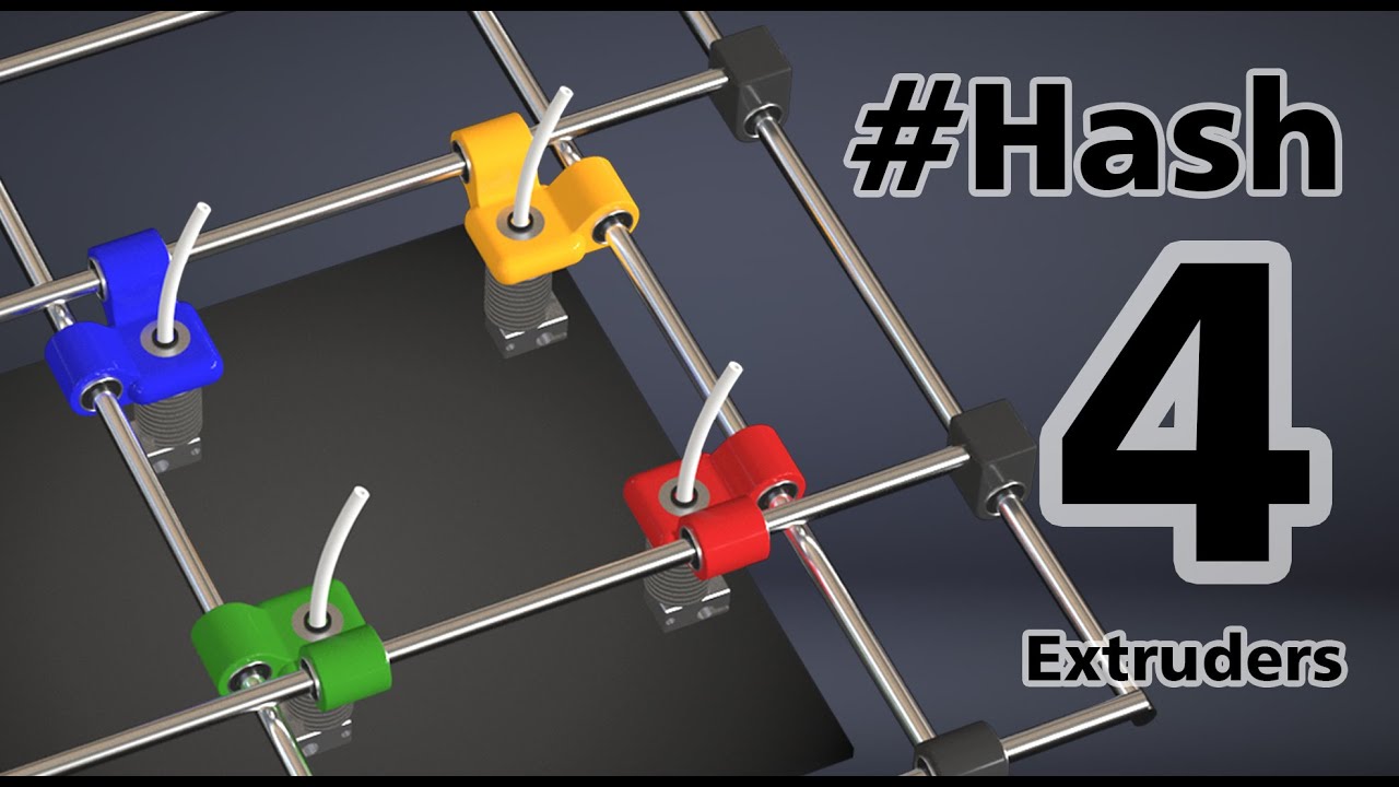
Quick Demo of Hash 3D Printer Kinematics
 vagrant meadow
the quad mirrored print is genius
alpine nest
i hope this tensioner works, where annoying enough to get a idea on how to route 2 pair of belts next to each other and how to tighten them somehow

and thats the easy axis, the X axis will be fun
vagrant meadow
i can see you've been thinking about this for a while 👍
 sterile briar
Whoooow
alpine nest
looks like i have to add spacers to the sides if i want to enclose the printer and keep double shear mounts for the Stepper
 alpine nest
in the progress of redesigning the entire beltpath to have a easier time overall with routing belts
 alpine nest
got half the X Axis Motionsystem now drawn up, changed a few bits here and there

i try to keep stuff reuseable where possible, the 4 bearing blocks and stepper mounts for the X axis are the same on each corner, just the stacking of the Pulleys for the Active idler and Stepper change
 hard gorge
yaaaaaaas
 solemn aspen
alpine nest
got half the X Axis Motionsystem now drawn up, changed a few bits here and there
ballscrew2s?
alpine nest
solemn aspen
ballscrew2s?
No
solemn aspen
alpine nest
No
aw
alpine nest
solemn aspen
aw
im not made of money and i expect to spend on the mainboards alone close to 500€
solemn aspen
alpine nest
im not made of money and i expect to spend on the mainboards alone close to 500€
Is it a pc?
hard gorge
How many steppers do you need?
Should get by with two Duet 3 mini+ with the 2+ expansion, one in can-fd expansion mode
That’ll provide 14 steppers
Which is not enough you need 15
So three duet 3 mini (that would be less than 500)
Unless you want toolboards for the print head
Then two duet 3 mini, one with 2+ expansion, and 4 roto tool heads
(That would be more than 500)
alpine nest
15, plan where to grab a 6HC with 2 3HC and 4 1LC
just endstops will probably maxout the IO pins on the 6hc...
hard gorge
Unless you need the 2160s, take one mini 5 instead of the 3HCs
You know you can use some of the outputs as inputs right?
Also how many endstops will there be? One per axis?
If you use the 1LCs put the endstops on the toolheads
alpine nest
hard gorge
Also how many endstops will there be? One per axis?
One per stepper
hard gorge
That ain’t working with RRF
Only one endstop per axis
You can have extra endstops if you want them to trigger events to stop the machine later during operation when they get triggered
(Also you can use out pins als inputs)
alpine nest
hard gorge
Only one endstop per axis
I run 2 endstops on my idex rn and it works? Or does it not support it outside of z axis? Because sensorless it also works
(on the k3)
hard gorge
the idex has one for X and one for U axis
its just a single physical rail
oh wait
you have four heads
each needs to home individually in global X and Y
but it will be one each for
XYUVWABC
(you could use dual endstops on ome physical rail for auto squaring , and then pair the axis homing per pair of extruders, still eight endstops)
alpine nest
hard gorge
(you could use dual endstops on ome physical rail for auto squaring , and then p...
That where the plan auto squaring.
Also the dual endstops on my idex are in z for the same purpose
hard gorge
Yeah but those are combined for one end
alpine nest
Will postpone the headache to figure that out to the day i get around building it
alpine nest
@desert sun ^above is a reason for RRF to remap Axis during a print
hard gorge
still unconvinced that axis remapping is needed
alpine nest
so i didnt liked the X axis stepper mounting solution.
since i can order parts from laserhub over my workplace im considering to get 2 10mm steel Halos made
now the challenge is to figure out how to get bearings securely installed onto that, cant machine fitments for them at work because the plate is to large for our current mills

(also it has been a year lol)
 final flare
holy shit this is insane
alpine nest
hmm i like this a lot better than the original implementation
not sure if tossing 200€ worth of igus stuff on it will be the way tho

also opted for a bit beefier linear rods, the original ones might have worked but i like this better, fits the look of the machine a bit more too
alpine nest
final flare
holy shit this is insane
we will see if it will be insane
 desert sun
Its most definitely insane, in the best possible way
alpine nest
getting the halo plates made is a lot cheaper than expected.
might have to make the lower plate 2mm thinner but then i can get it lasercut for 165€ (considering its rn 660x660x8mm thats really good)
 vast mural
alpine nest
so i didnt liked the X axis stepper mounting solution.
since i can order parts f...
Holy shit.
I'll finish Splenda just so I can call u out if u don't finish this I love it
alpine nest
vast mural
I'll finish Splenda just so I can call u out if u don't finish this I love it
Idk if it ever will be finished
vast mural
alpine nest
Idk if it ever will be finished
Coward
alpine nest
vast mural
Coward
My folk is known to be slow, it took them 632 years to finish a single building
alpine nest
@lapis bone got a smart idea in how to secure a Bearing inside a lasercut stainless plate?
rn i would go with a printed holder that gets pressed into the holt to make it a somewhat tight fit.
 lapis bone
alpine nest
<@374587076718624768> got a smart idea in how to secure a Bearing inside a laser...
I'd laser cut a pilot and drill it out (optimally ream, but that's effort) so I can glue the bearing in, that's the lowest effort solution that should still give you full performance
alpine nest
reaming would be a bit annoying, also a 20mm reamer is quite a bit of a ask tbh
drilling that would be already annoying in stainless.
sadly the lasercut parts are to large for the mills at work, otherwise that would be the obvious solution
lapis bone
I'm afraid that plastic is just too squishy and compliant
alpine nest
yea thats my concern too
maybe i just make it match in CAD and hope the laser is reasonable accurate enough to get some sort of fitment
lapis bone
alpine nest
maybe i just make it match in CAD and hope the laser is reasonable accurate enou...
I assume they don't list tolerances?
lapis bone
Way too loose, you don't want a 0,3 mm gap to be bridged
alpine nest
making it 26mm and installing a brass bushing might work
its soft enough to drill it open again i guess
lapis bone
Tbf I don't have any experience with reaming on my own, especially reaming stainless, so I just don't know how bad it is
alpine nest
reaming stainless is annoying
and a 20mm one will need some beefy drillpress
sadly i cant find any flange bearings with a 5mm bore, otherwise that would be one way to go i guess
lapis bone
alpine nest
sadly i cant find any flange bearings with a 5mm bore, otherwise that would be o...
F625?
alpine nest
i think thats badly translated, a bearing with a housing and a screw on flange
lapis bone
I wonder if you could machine your own bearing blocks at work, that's the preem solution
lapis bone
alpine nest
i think thats badly translated, a bearing with a housing and a screw on flange
Ah, bearing block
alpine nest
hmm maybe i can just take the printed holder i have designed rn but get it SLM printed out of alu and open up the hole it sits in a bit
the holder is screwed onto the plate ive wanted to fit it in so the plate would take the load
lapis bone
AliX has these, but dunno if they're any good
https://a.aliexpress.com/_EJffmTa
